metrologic instruments, inc. - vvv system s.r.o ... · metrologic instruments, inc. ... scanner and...
TRANSCRIPT

METROLOGIC INSTRUMENTS, INC.
IS6520/MS6520 Cubit® SeriesOmnidirectional Bar Code Scanner
Installation and User’s Guide


ii
LOCATIONS
Corporate Headquarters North America Metrologic Instruments, Inc. Customer Service: 1-800-ID-METRO
90 Coles Road Tel: 856-228-8100Blackwood, NJ 08012-4683 Fax: 856-228-6673
Email: [email protected]: www.metrologic.com
European Headquarters Germany, Metrologic Instruments GmbH Tel: +49 89 89019 0Middle East and Africa Dornierstrasse 2 Fax: +49 89 89019 200
82178 Puchheim b. Email: [email protected], Germany Germany Email: [email protected]
Spain Metrologic Eria lbérica SL Tel: +34 913 272 400Julián Camarillo 29, D-1 Fax: +34 913 273 829Edificio Diapasón Email: [email protected] Madrid
Italy Metrologic Instruments Italia srl Tel: +39 0 51 6511978Via Emilia 70 Fax: +39 0 51 652133740064 Ozzano dell’Emilia (BO) Email: [email protected]
France Metrologic Eria France SA Tel: +33 (0) 1 48.63.78.7869 Rue de la Belle Etoile Fax: +33 (0) 1 48.63.24.94ZI Paris Nord II, BP 50057 Email: [email protected] – ROISSY CDG CEDEX
United Kingdom Metrologic Instruments UK Limited Tel: +44 (0) 1256 36590058 Tempus Business Centre Fax: +44 (0) 1256 365955Kingsclere Road, Basingstoke Email: [email protected] RG21 6XG
Russia Metrologic Russia Tel: +7 095Bolshaya Novodmitrovskaya 14RU-125015 Email: [email protected] Russia
Asia
Singapore Metrologic Asia (Pte) Ltd Tel: 65-6842-7155No. 8 Kaki Bukit Place Fax: 65-6842-71664th Floor Email: [email protected] 416186
China Metro (Suzhou) Technologies Co., Ltd. Tel: 86-512-62572511221 Xing Hai Street Fax: 86-512-62571517Suzhou Industrial Park Email: [email protected], China215021
Japan Metrologic Japan Co., Ltd. Tel: 81-03-3839-8511Matsunoya Building, 6 Floor Fax: 81-03-3839-85193-14-8 Higashiueno Email: [email protected], Tokyo 110-0015 Japan
South America
Brazil Metrologic do Brasil Ltda. Tel: 55-11-5182-8226Rua da Paz 2059 Fax: 55-11-5182-8315CEP 04713-002 Email: [email protected]ácara Santo AntônioSão Paulo, SP, Brasil
Outside Brazil Metrologic South America Tel: 55-11-5182-7273Rua da Paz 2059 Fax: 55-11-5182-7198CEP 04713-002 Email: [email protected]ácara Santo AntônioSão Paulo, SP, Brasil
Copyright© 2003 by Metrologic Instruments, Inc. All rights reserved. No part of this work may be reproduced, transmitted, or stored in any form or by anymeans without prior written consent, except by reviewer, who may quote brief passages in a review, or provided for in the Copyright Act of 1976.
Products and brand names mentioned in this document are trademarks of their respective companies.

iii
TABLE OF CONTENTS
Introduction ...............................................................................................1
Scanner and Accessories .........................................................................2
Quick Start.................................................................................................3
Installing the IS6520-41/MS6520-41 to the Host System.........................4
Installing the IS6520-47/MS6520-47 to the PC ........................................5
Disconnecting the PowerLink Cables from the Scanner ..........................6
Scanner Parts ...........................................................................................7
Mounting Holes .........................................................................................7
Stands .......................................................................................................8
Audible Indicators......................................................................................9
Failure Modes .........................................................................................10
Visual Indicators......................................................................................11
Programming Modes...............................................................................12
Labels......................................................................................................15
Maintenance............................................................................................15
Optimal Low and Close Depth of Field ...................................................16
Optimal High and Normal Depth of Field ................................................17
Far Depth of Field ...................................................................................18
Troubleshooting Guide............................................................................19
Appendix A
Design Specifications ..........................................................................23
Appendix B
Default Settings ...................................................................................25

iv
TABLE OF CONTENTS
Appendix C
Scanner Pinout Connections ...............................................................29
Cable Connector Configurations .........................................................29
Appendix D
Warranty and Disclaimer .....................................................................31
Appendix E
Notices .................................................................................................32
Appendix F
Patents.................................................................................................34
Index........................................................................................................35


1
INTRODUCTION
Metrologic's Cubit® is a compact, omnidirectional bar code scanner that can beused as a presentation scanner or as the scanning component in OriginalEquipment Manufacturer (OEM) applications. Incorporating the latest inscanning technology Cubit can scan and decode all standard bar codes in anyorientation.
As an OEM product, the IS6520 is both easy to use and install. The IS6520 isequipped with three threaded mounting holes, serial programming and PowerLinkquick-disconnect cables. The modular design of Cubit allows the unit to betailored to meet the needs of a specific application.
As a retail scanner, the MS6520’s user-friendly mounting bracket bolts securelyto the countertop or wall for fixed-mount scanning. Cubit’s small size andaggressive scan pattern make it ideal for convenience, sporting goods, appareland toy/hobby stores.
Furthermore, Cubit has the option of direct connection to a 5-Volt power sourceor plug-in the Metrologic power supply provided with the scanner.
SCANNER INTERFACE
6520-41 Full RS-232C and Light Pen Emulation
6520-47 Keyboard Wedge, Stand Alone Keyboard andRS-232C Transmit/Receive

2
SCANNER AND ACCESSORIES
The following is a list of the parts included in the IS6520/MS6520 Kit.
• Cubit® IS6520/MS6520 - Omnidirectional Scanning Engine
• Installation and User’s Guide* – MLPN 00-02421
• MetroSelect® Scanner Configuration Guide*MLPN 00-02407 or MLPN 00-02561
*Available for download on Metrologic’s website, www.metrologic.com.
The following items are dependent on the type of IS6520/MS6520 Kit ordered.Some items may not be included in your kit.
• AC to DC Power Transformer - Regulated 5.2 VDC @ 650 mA output.One of the following may be included:
120 VAC United States – MLPN 45-45593220 VAC – 240 VAC Continental European – MLPN 45-45591220 VAC – 240 VAC United Kingdom – MLPN 45-45592
• PowerLink Cable with built in power jack (IS6520-41/MS6520-41 only)One of the following may be included:
Standard - MLPN 53xxx* - 2.7 m (9') coiled cord, long strain reliefOr
Optional - MLPN 54xxx* - 2.1 m (7') straight cord, short strain relief
*xxx specifies connection to the host
• Keyboard Wedge Powerlink and Adapter Cable – MLPN 54-54002
Powerlink cable with a 5-pin DIN female connector and a 6-pin mini Din maleconnector and an adapter cable with a 5-pin DIN male connector and a 6-pinmini DIN female connector. (IS650-47/MS6520-47 only)
• Mounting Hardware - Three M3 screws are included for mountingpurposes.
• Tilt Stand - MLPN 46-46486
• Fixed Vertical Stand - MLPN 46-46145
To order additional items, contact the dealer, distributor or call Metrologic'sCustomer Service Department at 1-800-ID-METRO (1-800-436-3876).

3
QUICK START
1. Connect the 10-pin RJ45 male connector into the jack on the Cubit®
IS6520/MS6520. You will hear a ‘click’ when the connection is made.
2. Connect the L-shaped plug of the power supply into the power jack on thePowerLink cable.
3. Connect the power supply into an AC outlet. Make sure the AC inputrequirements of the power supply match the AC outlet.
4. When the IS6520 is ready to scan, the green LED will turn on, the red LEDwill flash and the scanner will beep once.
5. Place a bar code in front of the scanning window. The scanner will beeponce and flash the red LED if the bar code was successfully decoded.
NOTE: Cubit® is shipped from the factory programmed with defaultsettings. Refer to the MetroSelect® Programming Guide forinstructions on how to configure the scanner.

4
INSTALLING THE IS6520-41/MS6520-41 TO THE HOST SYSTEM
1. Turn off the host system.
2. Connect the 10-pin RJ45 male connector into the jack on the Cubit®IS6520/MS6520. You will hear a ‘click’ when the connection is made.
Note: If the Cubit IS6520 is receiving power from the host system, skip tostep #5. (See caution statement below)
3. Connect the L-shaped plug of the power supply into the power jack on thePowerLink cable.
4. Connect the power supply into an AC outlet. Make sure the AC inputrequirements of the power supply match the AC outlet.
5. Connect the PowerLink cable to the proper port on the host system.
6. Turn on the host system.
Note: Plugging the scanner into a port on the host system does not guaranteethat scanned information will be communicated properly to the hostsystem. The scanner is shipped from the factory programmed withdefault settings. Please refer to the MetroSelect® Programming Manual(MLPN 2407) for instructions on changing the scanner’s configuration. Inaddition, please check that the scanner and host system are using thesame communication protocol.
Caution:
To maintain compliance with applicable standards, all circuits connected to the scannermust meet the requirements for SELV (Safety Extra Low Voltage) according toEN 60950.
To maintain compliance with standard CSA C22.2 No. 950/UL 1950 and norm EN 60950,the power source should meet applicable performance requirements for a limited powersource.

5
&
INSTALLING THE IS6520-47/MS6520-47 TO THE PC
1. Turn off the PC.
2. Connect the 10-pin RJ45 male connector into the jack on the Cubit®IS6520/MS6520. You will hear a ‘click’ when the connection is made.
3. Connect the L-shaped plug of the power supply into the power jack on thePowerLink cable. Refer to Manufacturer’s Recommendation below.
4. Connect the power supply into an AC outlet. Make sure the AC inputrequirements of the power supply match the AC outlet.
5. Disconnect the keyboard from the PC.
6. The PowerLink cable is terminated with a 5-pin DIN female connector on oneend, and a 6-pin mini DIN male on the other. Metrologic will supply anadapter cable with a 5-pin DIN male connector on one end and a 6-pin miniDIN female connector on the other. According to the termination required,connect the appropriate end of the adapter cable to the PowerLink cable,leaving the necessary termination exposed for connecting to the keyboardand the keyboard port on the PC. Refer to Appendix C page 31 for pinassignments.
7. Connect to the PowerLink cable to the keyboard and the keyboard port onthe PC.
8. Power up the PC.
Manufacturer’s Recommendation:Metrologic recommends the use of an external power supply with IS6520-47/MS6520 Keyboard Wedge applications. Powering the IS6520-47/MS6520directly from the computer keyboard connector could interfere with the operationof the scanner or the computer. Not all computers supply the same currentthrough the keyboard port, explaining why a scanner would work on onecomputer and not another.
Caution:To maintain compliance with applicable standards, all circuits connected to the scanner must meetthe requirements for SELV (Safety Extra Low Voltage) according to EN 60950.
To maintain compliance with standard CSA C22.2 No. 950/UL 1950 and norm EN 60950, the powersource should meet applicable performance requirements for a limited power source.

6
DISCONNECTING THE POWERLINK CABLES FROM THE SCANNER
Before removing the cable from the scanner, Metrologic recommends that thepower on the host system is off and the power supply has been disconnectedfrom the PowerLink cable.
1. Locate the small ‘pin-hole’ on the back of the scanner.
2. Bend an ordinary paperclip into the shape shown above.
3. Insert the paperclip (or other small metallic pin) into the small ‘pin-hole’.
4. You will here a faint ‘click’. Pull gently on the strain-relief of the PowerLinkcable and it will slide out of the scanner.
&

7
SCANNER PARTS
A. SpeakerServes as an audible indicator.
B. Green & Red LEDsDuring normal operation, the greenLED is on. This indicates that thelaser is on and the unit is ready toscan. On a successful read of a barcode, the red LED will turn on.After communication to the host iscomplete, the red LED will turn off.The LEDs are also used asdiagnostic indicators and modeindicators.
C. Output WindowLaser light emits form this aperture.
D. PowerLink CableThe IS6520/MS6520 scanner has a10-pin modular jack. The 10-pinmodular plug on the PowerLinkcable connects into theIS6520/MS6520.
MOUNTING HOLES
Each IS6520/MS6520 Cubit® isequipped with three threaded mountingholes located on the back of thescanner. The following diagram showsthe exact location of each mountinghole. The mounting holes are 6millimeters deep and are threaded foruse with 3 millimeter screws.
Caution: Using a screw that is longerthan 6 millimeters canpotentially damage thescanner.
AD
B
C
8
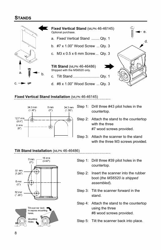
STANDS
Fixed Vertical Stand (MLPN 46-46145)Optional purchase.
a. Fixed Vertical Stand ........ Qty. 1
b. #7 x 1.00” Wood Screw ... Qty. 3
c. M3 x 0.5 x 6 mm Screw... Qty. 3
Tilt Stand (MLPN 46-46486)Shipped with the MS6520 only.
c. Tilt Stand .......................... Qty. 1
d. #8 x 1.00” Wood Screw ... Qty. 3
Fixed Vertical Stand Installation (MLPN 46-46145)
Step 1: Drill three #43 pilot holes in thecountertop.
Step 2: Attach the stand to the countertopwith the three#7 wood screws provided.
Step 3: Attach the scanner to the standwith the three M3 screws provided.
Tilt Stand Installation (MLPN 46-46486)
Step 1: Drill three #39 pilot holes in thecountertop.
Step 2: Insert the scanner into the rubberboot (the MS6520 is shippedassembled).
Step 3: Tilt the scanner forward in thestand.
Step 4: Attach the stand to the countertopusing the three#8 wood screws provided.
Step 5: Tilt the scanner back into place.
b.
c.
a.
e.
d.

9
AUDIBLE INDICATORS
When the IS6520/MS6520 scanner is in operation, it provides audible feedback.These sounds indicate the status of the scanner. Eight settings are available forthe tone of the beep (normal, 6 alternate tones and no tone). To change thetone, refer to the MetroSelect® Programming Guide MLPN 2407.
One BeepWhen the scanner first receives power, the green LED willturn on, then the red LED will flash and the scanner willbeep once. (The red LED will remain on for the duration ofthe beep.) The scanner is ready to scan.
When the scanner successfully reads a bar code, the redLED will flash and the scanner beeps once (if programmedto do so). If the scanner does not beep once and the greenlight does not flash, then the bar code has not beensuccessfully read.
Razzberry ToneThis tone is a failure indicator. Refer to “FailureModes" page 10.
Three Beeps - During OperationDuring operation of the scanner, the red LED will flash whilethe scanner simultaneously beeps three times (while goinginto programming mode).
The red LED will continue to flash until the unit exitsprogram mode. Upon exiting program mode, the scannerwill beep three times and the red LED will stop flashing.When configured, 3 beeps can also indicate acommunications timeout during normal scanning mode.
When using one-code-programming, the scanner will beepthree times (the current selected tone), followed by a shortpause then by a high tone and a low tone. This tells theuser that the single configuration bar code has successfullyconfigured the scanner.
Three Beeps - On Power UpThis is a failure indicator. Refer to “Failure Modes” on page10.

10
FAILURE MODES
Flashing Green and One Razzberry ToneThis indicates the scanner has experienced a lasersubsystem failure. Return the unit for repair at anauthorized service center.
Flashing Green and Red and Two RazzberryTonesThis indicates the scanner has experienced a motor failure.Return the unit for repair at an authorized service center.
Continuous Razzberry Tone with Both LEDs OffIf, upon power up, the scanner emits a continuous razzberrytone, then the scanner has an electronic failure. Return theunit for repair at an authorized service center.
Three Beeps - On Power UpIf the scanner beeps 3 times on power up then, the non-volatile memory that holds the scanner configuration hasfailed. Return the unit for repair at an authorized servicecenter.

11
VISUAL INDICATORS
There is a red LED and a green LED on IS6520/MS6520. When the scanner ison, the flashing or stationary, activity of the LEDs indicates the status of thecurrent scan and the scanner.
No Red or Green LEDThe LEDs will not be illuminated if the scanner is not receivingpower from the host or transformer.
Steady GreenWhen the laser is active, the green LED is illuminated. Thegreen LED will remain illuminated until the laser is deactivated.During the power save mode, the laser will turn on and turn off.During this period, the green LED remains illuminated.
Steady Green and Single Red FlashWhen the scanner successfully reads a bar code, the red LEDwill flash and the scanner will beep once. If the red LED does notflash or the scanner does not beep once, then the bar code hasnot been successfully read.
Steady Green and Steady RedAfter a successful scan, the scanner transmits the data to thehost device. Some communication modes require that the hostinform the scanner when data is ready to be received. If the hostis not ready to accept the information, the scanner's red LED willremain on until the data can be transmitted.
Steady Green and Flashing RedThis indicates the scanner is in program mode. A razzberry toneindicates that an invalid bar code has been scanned in this mode.
Steady Red, Green OffThis indicates the scanner may be waiting for communicationfrom the host.

12
PROGRAMMING MODES
The IS6520/MS6520 Cubit® has 3 modes of programming.
Bar Codes: Cubit can be configured by scanning the bar codes located in theMetroSelect® Configuration Guide (MLPN 2407). Please refer to this guide forinstructions. This manual can be downloaded for FREE from Metrologic’swebsite (www.metrologic.com).
MetroSet®: This user-friendly Windows-based configuration program allows youto simply ‘point-and-click’ at the desired scanner options. This program can bedownloaded for FREE from Metrologic’ website (www.metrologic.com), or set-updisks can be ordered by calling1-800-ID-METRO.
Serial Programming: This mode of programming is ideal for OEM applications.This mode gives the end-user the ability to send a series of commands using theserial port of the host system. The commands are equivalent to the numericalvalues of the bar codes located in the MetroSelect Configuration Guide (MLPN2407).
How does Serial Programming work?
1. Each command sent to the scanner is the ASCII representation of eachnumeral in the configuration bar code. The entire numeric string is framedwith an ASCII [stx] and an ASCII [etx].
EXAMPLE #1: Command for Disabling CodabarCommand = [stx]100104[etx]String Sent to Scanner = 02h 31h 30h 30h 31h 30h 34h 03h(All values are hexadecimal).
2. If the command sent to the scanner is valid, the scanner will respond with an[ack].
3. If the command sent to the scanner in invalid, the scanner will respond with a[nak].
NOTE: If this occurs, the end-user must start over at the very beginning ofthe configuration sequence. Simply re-tranmsitting the invalidcommand will not work, you must start over.
4. During programming, the motor and laser remain active. YOU CANNOTSCAN ANY BAR CODES WHILE IN PROGRAM MODE.
5. There is a 20 second window between commands. If a 20 second timeoutoccurs, the scanner will send a [nak] and you must start over.

13
PROGRAMMING MODES (CONTINUED)
6. To enter serial program mode, send the following command [stx]999999[etx].
7. To exit serial program mode, send the following command [stx]999999[etx],the scanner will respond with an [ack] and a long beep.
8. This mode uses the current Baud Rate, Parity, Stop Bits and Data Bitssettings that are configured in the scanner. The default settings of thescanner are 9600, Space, 2, 7 respectively. If a command is sent to thescanner to change any of these settings, the change will NOT take effectuntil after serial program mode is exited.
EXAMPLE #2: The following example will set the scanner to the factorydefault settings, Disable Scanning of Code 128 bar codes, change thebeeper tone, and add a “G” as a programmable prefix.
HOST SCANNER
FEATURE COMMAND ASCII REPRESENTATION RESPONSE
Enter Program Mode [stx]999999[etx] 02h 39h 39h 39h 39h 39h 39h 03h [ack] or 06h
Load Defaults [stx]999998[etx] 02h 39h 39h 39h 39h 39h 38h 03h [ack] or 06h
Disable Code 128 [stx]100113[etx] 02h 31h 30h 30h 31h 31h 33h 03h [ack] or 06h
Alternate Tone 1 [stx]318565[etx] 02h 33h 31h 38h 35h 36h 35h 03h [ack] or 06h
Prog. Prefix #1 [stx]903500[etx] 02h 39h 30h 33h 35h 30h 30h 03h [ack] or 06h
Code Byte 0 [stx]0[etx] 02h 30h 03h [ack] or 06h
Code Byte 7 [stx]7[etx] 02h 37h 03h [ack] or 06h
Code Byte 1 [stx]1[etx] 02h 31h 03h [ack] or 06h
Exit Program Mode [stx]999999[etx] 02h 39h 39h 39h 39h 39h 39h 03h [ack] or 06h
The scanner will emit a long beep!
The commands sent to the scanner do not include the small superscripted ‘3’that you see in front of each bar code string in the MetroSelect® manual.THE ‘3’ SHOULD NOT BE SENT, IT IS A CODE TYPE DESIGNATIONONLY!
As you will note for commands requiring additional bar codes to be scanned(such as prefixes, suffixes, timeouts, etc.), simply send the code bytes in thesame order that you would normally scan the bar codes.

14
PROGRAMMING MODES (CONTINUED)
EXAMPLE #3: The following example shows the events that occur when aninvalid bar code is sent. This sample will load the factory default settingsand then set the baud rate to 19200.
HOST SCANNER
FEATURE COMMAND ASCII REPRESENTATION RESPONSE
Enter Program Mode [stx]999999[etx] 02h 39h 39h 39h 39h 39h 39h 03h [ack] or 06h
Load Defaults [stx]99999:[etx] 02h 39h 39h 39h 39h 39h 3Ah 03h [nak] or 15h
Invalid command was sent, you must start over!
Enter Program Mode [stx]999999[etx] 02h 39h 39h 39h 39h 39h 39h 03h [ack] or 06h
Load Defaults [stx]999998[etx] 02h 39h 39h 39h 39h 39h 39h 03h [ack] or 06h
19200 Baud Rate [stx]415870[etx] 02h 34h 31h 35h 38h 37h 30h 03h [ack] or 06h
Exit Program Mode [stx]999999[etx] 02h 39h 39h 39h 39h 39h 39h 03h [ack] or 06h
The scanner will emit a long beep!
This example illustrates 2 important points.
First, if an invalid command is sent from the host, the scanner responds witha [nak] and the end-user must start over from the beginning.
Second, if a command is sent to change the Baud Rate, the new baud ratedoes not take effect until after the end-user exits program mode.
ABREVIATED ASCII TABLECharacter Hex Value Decimal Value
[STX] 02h 2
[ETX] 03h 3
[ACK] 06h 6
[NAK] 15h 21
0 30h 48
1 31h 49
2 32h 50
3 33h 51
4 34h 52
5 35h 53
6 36h 54
7 37h 55
8 38h 56
9 39h 57

15
LABELS
Each scanner has a label on the back of the unit. This label has the modelnumber, date of manufacture, serial number, CE and caution information. Thefollowing is an example of this label:
MAINTENANCE
Smudges and dirt can interfere with the proper scanning of a bar code.Therefore, the output window will need occasional cleaning.
1. Spray glass cleaner onto lint free, non-abrasive cleaning cloth.
2. Gently wipe the scanner window.

16
OPTIMAL LOW AND CLOSE DEPTH OF FIELD
Minimum Bar Code Element WidthA B C D E F G H J K
mm - .15 - .17 - - .25 .33 .53 -mils - 5.7 - 6.8 - - 10 13 21 -
Note: The same depth of field is achieved when programming Cubit® foreither Optimal Low Depth of Field or Close Depth of Field.
0
25
50
75
100
125
150
175
200
250
225
BD
GH
J
123
4549
73
82
95
105
40
DISTANCE:SCANNER FACE
TO BAR CODE (mm)
WIDTH OF SCAN FIELD (mm)
17
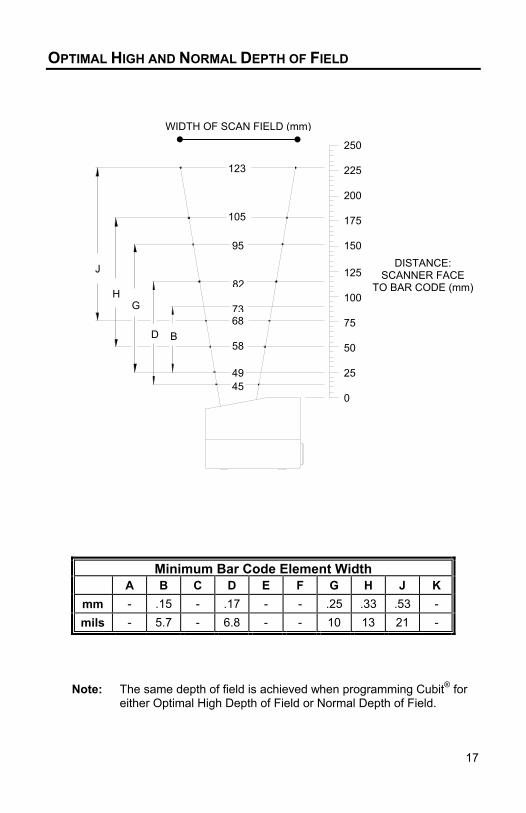
OPTIMAL HIGH AND NORMAL DEPTH OF FIELD
Minimum Bar Code Element WidthA B C D E F G H J K
mm - .15 - .17 - - .25 .33 .53 -mils - 5.7 - 6.8 - - 10 13 21 -
Note: The same depth of field is achieved when programming Cubit® foreither Optimal High Depth of Field or Normal Depth of Field.
0
25
50
75
100
125
150
175
200
250
225
DISTANCE:SCANNER FACE
TO BAR CODE (mm)
D
GH
J
B
123
58
6873
82
95
105
4549
WIDTH OF SCAN FIELD (mm)

18
FAR DEPTH OF FIELD
Minimum Bar Code Element WidthA B C D E F G H J K
mm - .15 - .17 - - .25 .33 .53 -mils - 5.7 - 6.8 - - 10 13 21 -
0
25
50
75
100
125
150
175
200
250
225
DISTANCE:SCANNER FACE
TO BAR CODE (mm)
D
G
H
J
B
123
7782
9195
105
114
49
73
45
WIDTH OF SCAN FIELD (mm)

19
TROUBLESHOOTING GUIDE
The following guide is for reference purposes only. Contact a Metrologicrepresentative at 1-800-ID-METRO or 1-800-436-3876 to preserve the limitedwarranty terms.
All Interfaces
IS6520/MS6520 Series Troubleshooting Guide
SYMPTOMS POSSIBLE CAUSE(S) SOLUTION
No LEDs, beepor motor spin
No power is beingsupplied to thescanner
Check transformer, outlet andpower strip. Make sure the cableis plugged in to the scanner
No LEDs, beep No power is beingsupplied to thescanner front host
Some host system’s cannotsupply enough current to powerOmni-Quest. Use the powersupply included with the scanner.
3 beeps onpower up
Non-volatile RAMfailure
Contact a MetrologicRepresentative, if the unit will nothold the programmedconfiguration
Continuousrazz tone onpower up
RAM or ROM failure Contact a MetrologicRepresentative, if the unit will notfunction
Razz tone andgreen LEDflash at powerup
VLD failure Contact a MetrologicRepresentative
Razz tone andboth LEDsflash at powerup
Scanner motor failure Contact a MetrologicRepresentative
Unit scans,Communicatesand beepstwice
Same symbol timeoutset too short
Adjust same symbol timeout for alonger time

20
TROUBLESHOOTING GUIDE (CONTINUED)
All Interfaces
IS6520/MS6520 Series Troubleshooting Guide (continued)
SYMPTOMS POSSIBLE CAUSE(S) SOLUTION
The unitpowers up, butdoes notscan and/orbeep
Beeper disabled. Notone selected
Enable beeper. Select tone
The unitpowers up, butdoes not scanand/or beep
Scanning a particularsymbology that is notenabled
UPC/EAN, Code 39, interleaved2 of 5, Code 93, Code 128 andCodabar are enabled by default.Verify that the type of bar codebeing read has been selected
The unitpowers up, butdoes not scanand/or beep
The scanner has beenprogrammed for acharacter length lock, ora minimum length andbar code being scanneddoes not satisfy theprogrammed criteria
Verify that the bar code that isbeing scanned falls into thecriteria. (Typical of Non-UPC/EAN codes.) (The scannerdefaults to a minimum of 4character bar code)
The unit scansa bar code, butlocks up afterthe first scan(red LED stayson)
The scanner isconfigured to supportsome form of hosthandshaking but is notreceiving the signal
If the scanner is setup to supportACK/NAK, RTS/CTS,XON/XOFF or D/E, verify thatthe host cable and host aresupporting the handshakingproperly
The unit scans,but the datatransmitted tothe host isincorrect
The scanner's dataformat does not matchthe host systemrequirements
Verify that the scanner's dataformat matches that required bythe host. Make sure that thescanner is connected to theproper host port

21
TROUBLESHOOTING GUIDE (CONTINUED)
All Interfaces
IS6520/MS6520 Series Troubleshooting Guide (continued)
SYMPTOMS POSSIBLE CAUSE(S) SOLUTION
Scanner beepsat some barcodes and NOTfor others of thesame bar codesymbology
The print quality of thebar code is suspect
Check print mode. The type ofprinter could be the problem.Change print settings. Forexample change to econo modeor high speed
Scanner beepsat some barcodes and NOTfor others of thesame bar codesymbology
The aspect ratio of thebar code is out oftolerance
Check print mode. The type ofprinter could be the problem.Change print settings, ie changeto econo mode or high speed
Scanner beepsat some barcodes and NOTfor others of thesame bar codesymbology
The bar code mayhave been printedincorrectly
Check if it is a check digit,character, or border problem
Scanner beepsat some barcodes and NOTfor others of thesame bar codesymbology
The scanner is notconfigured correctly forthis type of bar code
Check if check digits are setproperly
Scanner beepsat some barcodes and NOTfor others of thesame bar codesymbology
The minimum symbollength setting does notwork with the bar code
Check if the correct minimumsymbol length is set

22
TROUBLESHOOTING GUIDE (CONTINUED)
RS-232 only
IS6520/MS6520 Series Troubleshooting Guide (continued)
SYMPTOMS POSSIBLE CAUSE(S) SOLUTION
Powers up OKand scans OKbut does notcommunicateproperly to thehost
Com port at the host isnot working orconfigured properly
Check to make sure that thebaud rate, data bits, stops bitsand parity of the scanner and thecommunication port match andthe program is looking for "RS-232" data
Powers up OKand scans OKbut does notcommunicateproperly to thehost
Cable not connected tothe proper com port
Check to make sure that thebaud rate, data bits, stops bitsand parity of the scanner and thecommunication port match andthe program is looking for "RS-232" data
Powers up OKand scans OKbut does notcommunicateproperly to thehost
Com port not operatingproperly
Check to make sure that thebaud rate, data bits, stops bitsand parity of the scanner and thecommunication port match andthe program is looking for "RS-232" data
The host isreceiving databut the datadoes not lookcorrect
The scanner and hostmay not be configuredfor the same interfacefont
Check that the scanner and thehost are configured for the sameinterface font
Characters arebeing dropped
Intercharacter delayneeds to be added tothe transmitted output
Add some Intercharacter delayto the transmitted output byusing the MetroSelect ®Programming Guide MLPN 2407

23
APPENDIX A
Design Specifications
Operational
Light Source: VLD 650 ± 10 nm, 0.681 milliwatts (PEAK)Depth of Field: 0 mm to 176 mm (0” to 7”) for 0.33 mm
(13 mil) bar code at default setting(programmable)
Scan Speed: 1000 scan lines/secondScan Pattern: 5 fields of 4 parallel lines (omnidirectional)Scan Lines: 20Min Bar Width: 0.145 mm (5.7 mil)Decode capability: Autodiscriminates all standard bar codes; for
other symbologies call MetrologicSystem Interfaces: RS-232, Light Pen Emulation, Keyboard Wedge,
Stand Alone KeyboardPrint Contrast: 35% minimum reflectance differenceRoll, Pitch, Yaw: 360°, 60° ,60°Indicators: Green = laser on, ready to scan;
Red = good read, decodingBeeper Operation: 7 tones or no beep
Mechanical
Length: 102 mm (4.0")Width: 83 mm (3.25")Height (front edge): 70 mm (2.75")Height (back edge): 55 mm (2.25")Weight: 298 g (10.5 oz)Termination: 10 Position Modular RJ45Mounting Holes: 3 mm threaded; maximum depth of
6 mm (0.24”)

24
APPENDIX A (CONTINUED)
Design Specifications
Electrical
Power: 1.0 WInput Voltage: 5 VDC ± 0.25 VOperating Current: 200 mA typical @5VDCDC Transformers: Class 2; 5.2 VDC @ 650 mAEMC: FCC, ICES-003 & EN 55022 Class ALaser Class: CDRH Class IIa
EN 60825-1:1994/A11: 1996 CLASS 1
Environmental
Operating Temperature: -20°C to 40°C (-4°F to 104°F)Storage Temperature: -40°C to 60°C (-40°F to 140°F)Humidity: 5% to 95% relative humidity, non-condensingLight Levels: Up to 4840 Lux (450 footcandles)Contaminants: Sealed to resist airborne particulate contaminantsVentilation: None required
Specifications subject to change without notice.

25
APPENDIX B
Default SettingsMany functions of the scanner can be "programmed" - that is, enabled ordisabled. The scanner is shipped from the factory programmed to a set of defaultconditions. The default parameter of the scanner has an asterisk (*) in the chartson the following pages. If an asterisk is not in the default column then the defaultsetting is Off or Disabled. Every communication does not support everyparameter. If the communication supports a parameter listed in the charts on thefollowing pages, a check mark will appear.
Parameter Default RS-232* Light PenUPC/EAN * a a
Code 128 * a a
Code 93 * a a
Codabar a a
Interleaved 2 of 5 (ITF) * a a
MOD 10 Check on ITF a a
Code 11 a a
Code 39 * a a
Full ASCII Code 39 a a
MOD 43 Check on Code 39 a a
MSI-Plessey a a
MSI-Plessey, 10/10 Check Digit a a
MSI-Plessey, MOD 10 Check Digit * a a
Paraf Support a a
ITF Symbol Lengths Variable a a
Minimum Symbol Length 4 a a
Symbol Length Lock None a a
Bars High as Code 39 * a
Spaces High as Code 39 a
Bars High as Scanned a
Spaces High as Scanned a
DTS/SIEMENS

26
APPENDIX B (CONTINUED)
Parameter Default RS-232* Light PenDTS/NIXDORF *NCR F
NCR S
Poll Light Pen Source a
Beeper Tone Normal a a
Beep/Transmit Sequence BeforeTransmit a a
Communication Timeout None a a
Razzberry Tone on Timeout a a
Three Beeps on Timeout a a
No Beeps on Timeout * a a
Enter Power Save Mode 10 mins. a a
Same Symbol RescanTimeout: 200 msecs a a
Same Symbol RescanTimeout: 500 msecsProgrammable in 50 msec steps(MAX 6.35 seconds)
* a a
Same Symbol RescanTimeout: 1250 msecs a a
Same Symbol RescanTimeout: 2000 msecs a a
Intercharacter Delay Programmablein 1 msec steps(MAX 255 msecs)
1 msecs10 msecs in
KBWa
Number of Scan Buffers 1 a a
Transmit UPC-A Check Digit * a a
Transmit UPC-E Check Digit a a
Expand UPC-E a a
Convert UPC-A to EAN-13 a
Transmit Lead Zero on UPC-E a a
Convert EAN-8 to EAN-13 a
Transmit UPC-A Number System * a a

27
APPENDIX B (CONTINUED)
Parameter Default RS-232* Light PenTransmit UPC-A Manufacturer ID# * a a
Transmit UPC-A Item ID# * a a
Transmit Codabar Start/StopCharacters a
CLSI Editing a
Transmit Mod 43 Check Digit onCode 39 a
Transmit Code 39 Stop/StartCharacters a
Transmit Mod 10/ITF aTransmit MSI-Plessey CheckCharacters a
Parity Space a
Baud Rate 9600 a
8 Data Bits a
7 Data Bits * a
Transmit Sanyo ID Characters a
Nixdorf ID a
LRC Enabled a
UPC Prefix a
UPC Suffix a
Transmit AIM ID Characters a
STX Prefix a
ETX Suffix a
Carriage Return * a
Line Feed * a
Tab Prefix a
Tab Suffix a
“DE” Disable Command a
“FL” Laser Enable Command a
DTR Handshaking Support a
RTS/CTS Handshaking a
Character RTS/CTS * a

28
APPENDIX B (CONTINUED)
Parameter Default RS-232* Light PenMessage RTS/CTS a
XON/XOFF Handshaking a
ACK/NA K a
Two Digit Suppliments a as code 39
Five Digit Suppliments a as code 39
Bookland a as code 39977 (2 digit) SupplementalRequirement a a
Suppliments are not Required * a a
Two Digit Redundancy * a a
Five Digit Redundancy a a100 msec to Find SupplementProgrammable in 100 msec steps(MAX 800 msec)
* a a
Coupon Code 128 a as code 39
Programmable Code Lengths 7 aval. a a
Programmable Prefix Characters 10 avail. a
Suffix Characters a
Prefixes for individual Code Types
Editing a a
Inter Scan-Code DelayProgrammable (100 msec steps) 800 msec
Function/Control Key SupportMinimum Element WidthProgrammable in 5.6 µsec steps 1 msec a
Depth of Field
Optimal High Depth of Field * a a
Normal Depth of Field a a
Optimal Low Depth of Field a a
Close Depth of Field a a
Far Depth of Field a a

29
1 10
APPENDIX C
Scanner Pinout Connections
The IS6520/MS6520 scanner interfaces terminateto a 10-pin modular jack. The serial # labelindicates the interface enabled when the scanneris shipped from the factory.
IS6520-47 / MS6520-47Keyboard Wedge
IS6520-41 / MS6520-41 RS-232/LTPN
Pin Function Pin Function1 Ground 1 Ground2 RS-232 Transmit Output 2 RS-232 Transmit Output3 RS-232 Receive Input 3 RS-232 Receive Input4 PC Data 4 RTS Output5 PC Clock 5 CTS Input6 KB Clock 6 DTR Input/LTPN Source7 PC +5V 7 Reserved8 KB Data 8 LTPN Data9 +5VDC 9 +5VDC
10 Shield Ground 10 Shield Ground
Cable Connector Configurations
“Standard” PowerLink cable(MLPN 53000 or 54000)
9-pin D-type female connector to the PCPin Function
1 Shield Ground2 RS-232 Transmit Output3 RS-232 Receive Input4 DTR Input5 Power/Signal Ground6 Light Pen Data7 CTS Input8 RTS Output9 +5VDC*
* If a PowerLink power supply is plugged into the PowerLink cable, +5Vwill NOT be available on this pin. This pin is used when the host issupplying +5V to the scanner.
9-Pin D-Type Connector
9 5
6 1

30
APPENDIX C (CONTINUED)
Keyboard Wedge Powerlink and Adapter Cable (MLPN 54-54008)
The Keyboard Wedge PowerLink cable is terminated with a 5-pin DIN femaleconnector on one end, and a 6-pin mini DIN male on the other.
Metrologic will supply an adapter cable with a 5-pin DIN male connector on oneend and a 6-pin mini DIN female connector on the other.
According to the termination required, connect the appropriate end of the adaptercable to the PowerLink cable, leaving the necessary termination exposed forconnecting to the keyboard and the keyboard port on the PC.The pin assignments are as follows:
PowerLink Cable Adapter Cable
5-pin Female DIN 5-pin Male DINPin Function Pin Function1 Keyboard Clock 1 PC Clock2 Keyboard Data 2 PC Data3 No Connect 3 No Connect4 Power Ground 4 Power Ground5 +5 Volts DC 5 +5 Volts DC
6-pin Male Mini-DIN 6-pin Female Mini-DINPin Function Pin Function1 PC Data 1 Keyboard Data2 No Connect 2 No Connect3 Power Ground 3 Power Ground4 +5 Volts DC 4 +5 Volts DC5 PC Clock 5 Keyboard Clock6 No Connect 6 No Connect
42 1
36 5
6-Pin DIN, Male
2
14 5
3
5-Pin DIN, FemaleKeyboard WedgePowerLink Cable
5-Pin Din, Male 6-pin Mini Din, FemaleAdapter Cable
3
1 2
45 6
2
35 4
1

31
APPENDIX D
Warranty and DisclaimerLimited Warranty
The IS6520/MS6520 Cubit® scanners are manufactured by Metrologic at itsBlackwood, New Jersey, U.S.A. facility. The IS6520/MS6520 Cubit® scannershave a two (2) year limited warranty from the date of manufacture. Metrologicwarrants and represents that all IS6520/MS6520 Cubit® scanners are free of alldefects in material, workmanship and design, and have been produced andlabeled in compliance with all applicable U.S. Federal, state and local laws,regulations and ordinances pertaining to their production and labeling.
This warranty is limited to repair, replacement of Product or refund of Productprice at the sole discretion of Metrologic. Faulty equipment must be returned tothe Metrologic facility in Blackwood, New Jersey, U.S.A. or Puchheim, Germany.To do this, contact Metrologic’s Customer Service/Repair Department to obtain aReturned Material Authorization (RMA) number.
In the event that it is determined the equipment failure is covered under thiswarranty, Metrologic shall, at its sole option, repair the Product or replace theProduct with a functionally equivalent unit and return such repaired or replacedProduct without charge for service or return freight, whether distributor,dealer/reseller, or retail consumer, or refund an amount equal to the originalpurchase price.
This limited warranty does not extend to any Product which, in the solejudgement of Metrologic, has been subjected to abuse, misuse, neglect,improper installation, or accident, nor any damage due to use or misuseproduced from integration of the Product into any mechanical, electrical orcomputer system. The warranty is void if the case of Product is opened byanyone other than Metrologic’s repair department or authorized repair centers.THIS LIMITED WARRANTY, EXCEPT AS TO TITLE, IS IN LIEU OF ALL OTHER WARRANTIES ORGUARANTEES, EITHER EXPRESS OR IMPLIED, AND SPECIFICALLY EXCLUDES, WITHOUTLIMITATION, WARRANTIES OF MERCHANTABILITY AND FITNESS FOR A PARTICULARPURPOSE UNDER THE UNIFORM COMMERCIAL CODE, OR ARISING OUT OF CUSTOM ORCONDUCT. THE RIGHTS AND REMEDIES PROVIDED HEREIN ARE EXCLUSIVE AND IN LIEUOF ANY OTHER RIGHTS OR REMEDIES. IN NO EVENT SHALL METROLOGIC BE LIABLE FORANY INDIRECT OR CONSEQUENTIAL DAMAGES, INCIDENTAL DAMAGES, DAMAGES TOPERSON OR PROPERTY, OR EFFECT ON BUSINESS OR PROPERTY, OR OTHER DAMAGESOR EXPENSES DUE DIRECTLY OR INDIRECTLY TO THE PRODUCT, EXCEPT AS STATED INTHIS WARRANTY. IN NO EVENT SHALL ANY LIABILITY OF METROLOGIC EXCEED THEACTUAL AMOUNT PAID TO METROLOGIC FOR THE PRODUCT. METROLOGIC RESERVESTHE RIGHT TO MAKE ANY CHANGES TO THE PRODUCT DESCRIBED HEREIN.
Metrologic Instruments, Inc. Metrologic Instruments GmbH90 Coles Road Dornierstrasse 2Blackwood, NJ 08012-4683 82178 Puchheim bCustomer Service Department: Munich, Germany1-800-ID-METRO (1-800-436-3876) TEL: 49-89-89019-0TEL: 856-228-8100 FAX: 49-89-89019-200FAX: 856-228-6673
32
APPENDIX E
NoticesNoticeThis equipment has been tested and found to comply with limits for a Class A digital device, pursuant toPart 15 of the FCC Rules. These limits are designed to provide reasonable protection against harmfulinterference when the equipment is operated in a commercial environment. This equipment generates,uses and can radiate radio frequency energy and, if not installed and used in accordance with theinstruction manual, may cause harmful interference to radio communications. Operation of thisequipment in a residential area is likely to cause harmful interference, in which case the user will berequired to correct the interference at his own expense. Any unauthorized changes or modifications tothis equipment could void the users authority to operate this device.
This device complies with Part 15 of the FCC Rules. Operation is subject to the following two conditions:(1) This device may not cause harmful interference, and (2) this device must accept any interferencereceived, including interference that may cause undesired operation.
NoticeThis Class A digital apparatus complies with Canadian ICES-003.
RemarqueCet appareil numérique de la classe A est conforme à la norme NMB-003 du Canada.
CautionUse of controls or adjustments or performance of procedures other than those specified herein may resultin hazardous laser light exposure. Under no circumstances should the customer attempt to service thelaser scanner. Never attempt to look at the laser beam, even if the scanner appears to be nonfunctional.Never open the scanner in an attempt to look into the device. Doing so could result in hazardous laserlight exposure. The use of optical instruments with the laser equipment will increase eye hazard.
AtenciónLa modificación de los procedimientos, o la utilización de controles o ajustes distintos de losespecificados aquí, pueden provocar una luz de láser peligrosa. Bajo ninguna circunstancia el usuariodeberá realizar el mantenimiento del láser del escáner. Ni intentar mirar al haz del láser incluso cuandoeste no esté operativo. Tampoco deberá abrir el escáner para examinar el aparato. El hacerlo puedeconllevar una exposición peligrosa a la luz de láser. El uso de instrumentos ópticos con el equipo láserpuede incrementar el riesgo para la vista.
AttentionL'emploi de commandes, réglages ou procédés autres que ceux décrits ici peut entraîner de gravesirradiations. Le client ne doit en aucun cas essayer d'entretenir lui-même le scanner ou le laser. Neregardez jamais directement le rayon laser, même si vous croyez que le scanner est inactif. N'ouvrezjamais le scanner pour regarder dans l'appareil. Ce faisant, vous vous exposez à une rayonnementlaser qú êst hazardous. L'emploi d'appareils optiques avec cet équipement laser augmente le risqued'endommagement de la vision.
AchtungDie Verwendung anderer als der hier beschriebenen Steuerungen, Einstellungen oder Verfahren kanneine gefährliche Laserstrahlung hervorrufen. Der Kunde sollte unter keinen Umständen versuchen, denLaser-Scanner selbst zu warten. Sehen Sie niemals in den Laserstrahl, selbst wenn Sie glauben, daßder Scanner nicht aktiv ist. Öffnen Sie niemals den Scanner, um in das Gerät hineinzusehen. Wenn Siedies tun, können Sie sich einer gefährlichen Laserstrahlung aussetzen. Der Einsatz optischer Gerätemit dieser Laserausrüstung erhöht das Risiko einer Sehschädigung.
AttenzioneL’utilizzo di sistemi di controllo, di regolazioni o di procedimenti diversi da quelli descritti nel presenteManuale può provocare delle esposizioni a raggi laser rischiose. Il cliente non deve assolutamentetentare di riparare egli stesso lo scanner laser. Non guardate mai il raggio laser, anche se credete chelo scanner non sia attivo. Non aprite mai lo scanner per guardare dentro l’apparecchio. Facendolopotete esporVi ad una esposizione laser rischiosa. L’uso di apparecchi ottici, equipaggiati con raggilaser, aumenta il rischio di danni alla vista.

33
APPENDIX E (CONTINUED)
European Standard
Warning
This is a class A product. In a domestic environment this product may causeradio interference in which case the user may be required to take adequatemeasures.
Funkstöreigenschaften nach EN 55022:1998
Warnung!
Dies ist eine Einrichtung der Klasse A. Diese Einrichtung kann imWohnbereich Funkstörungen verursachen; in diesem fall kann vom Betrieberverlangt werden, angemessene Maßnahmen durchführen.
Standard Europeo
Attenzione
Questo e’ un prodotto di classe A. Se usato in vicinanza di residenze privatepotrebbe causare interferenze radio che potrebbero richiedere all’utilizzatoreopportune misure.
Attention
Ce produit est de classe “A”. Dans un environnement domestique, ce produitpeut être la cause d’interférences radio. Dans ce cas l’utiliseteur peut êtreamené à predre les mesures adéquates.

34
APPENDIX F
Patents
“Patent Information
This METROLOGIC product may be covered by one or more of the followingU.S. Patents:
U.S. Patent No.;
4,960,985; 5,081,342; 5,216,232; 5,260,553; 5,340,971; 5,525,789;5,557,093; 5,627,359; 5,637,852; 5,777,315; 5,789,731; 6,029,894;6,098,885; 6,209,789;
4,360,798; 4,369,361; 4,387,297; 4,460,120; 4,496,831; 4,593,186;4,607,156; 4,673,805; 4,736,095; 4,758,717; 4,816,660; 4,845,350;4,896,026; 4,923,281; 4,933,538; 4,992,717; 5,081,342; 5,015,833;5,017,765; 5,059,779; 5,117,098; 5,124,539; 5,130,520; 5,132,525;5,140,144; 5,149,950; 5,180,904; 5,200,599; 5,229,591; 5,247,162;5,250,790; 5,250,791; 5,250,792; 5,262,628; 5,280,162; 5,280,164;5,304,788; 5,321,246; 5,324,924; 5,396,053; 5,396,055; 5,408,081;5,410,139; 5,436,440; 5,449,891; 5,468,949; 5,479,000; 5,532,469;5,545,889;
No license right or sublicense is granted, either expressly or by implication,estoppel, or otherwise, under any METROLOGIC or third party intellectualproperty rights (whether or not such third party rights are licensed toMETROLOGIC), including any third party patent listed above, except for animplied license only for the normal intended use of the specific equipment,circuits, and devices represented by or contained in the METROLOGIC productsthat are physically transferred to the user, and only to the extent ofMETROLOGIC’S license rights and subject to any conditions, covenants andrestrictions therein.”
Other world wide patents pending.

35
INDEX
AAC input/outlet .............2, 3, 4, 5, 29Accessories ...................................2Approvals ........................15, 32, 33Assignments
Pin ...........................................29Audible ..........................................9Autodiscriminates ........................23
BBar code1, 3, 9, 11, 12, 15, 16, 17,
18, 20, 21, 25Bar width .....................................23Beep...... 3, 9, 10, 11, 19, 20, 21, 26
CCable .............................2, 3, 22, 30
communication ..................29, 30detachable.................1, 6, 29, 30pin assignments.................29, 30powerlink .....................4, 5, 6, 30
Caution ................ 4, 5, 7, 15, 32, 33CDRH..........................................24Ce................................................32Communication ...........4, 11, 22, 25Compliance ...........................32, 33Current ..............................9, 19, 24Customer service ....................2, 31
DDC transformer............................24Decode capability ........................23Default settings..........25, 26, 27, 28Depth of field ....... 16, 17, 18, 23, 28Design specifications...................23Disclaimer....................................31
EElectrical......................................24
FFailure indicator(s) ........................ 9Failure modes ......................... 9, 10
GGreen LED............................ 11, 19
HHost .............. 2, 4, 6, 11, 20, 22, 29
IIndicators .................... 9, 10, 11, 23
audible ...................................... 9LED............... 7, 9, 10, 11, 19, 20Visual ...................................... 11
Input voltage ............................... 24Installation............................. 4, 7, 8Interfaces .............. 1, 19, 20, 21, 23
KKeyboard wedge ........... 1, 2, 29, 30
LLabels ......................................... 15Light levels .................................. 24Light pen ................... 25, 26, 27, 28Light Pen......... 1, 23, 25, 26, 27, 28Light source ................................ 23List ................................................ 2
MMaintenance ............................... 15
NNotices.................................. 32, 33

36
INDEX
OOperating current ........................24Operating temperture ..................24Operation...........................9, 23, 32Operational..................................23Output window...............................7
PParts..........................................2, 7PC .................................................4Port..........................................5, 22Power supply ...................1, 2, 5, 29Powerlink...........................2, 3, 4, 6Programming guide .............3, 9, 12Programming modes .......12, 13, 14
QQuick start .....................................3
RRazzberry tone ............9, 10, 11, 26Red LED............................9, 11, 20Repair..........................................10RMA ............................................31RS-232 .......... 22, 23, 25, 26, 27, 28
SScan lines ................................... 23Scan pattern................................ 23Scan speed ................................. 23Service.............................. 2, 10, 31Specifications........................ 23, 24System interfaces ....................... 23
TTermination ............................. 5, 23Tones................................ 9, 10, 23Transformers............................... 24Troubleshooting ........ 19, 20, 21, 22
VVentilation ................................... 24Visual .......................................... 11Voltage........................................ 24
WWarranty ............................... 19, 31Weight......................................... 23Window ................................... 7, 15


July 2003
Printed in the USA
0 0 - 0 2 4 2 1 A