method and system for recalibration of an electronic control module
TRANSCRIPT
(12) United States Patent
US006571191B1
(10) Patent N0.: US 6,571,191 B1 York et al. (45) Date of Patent: May 27, 2003
(54) METHOD AND SYSTEM FOR 5,490,065 A 2/1996 Hoenninger et a1. ........ .. 701/29 RECALIBRATION OF AN ELECTRONIC 5,506,772 A 4/1996 KuboZono et al. .......... .. 701/29 CONTROL MODULE 5,506,773 A 4/1996 Takaba et al. .... .. 701/29
5,528,496 A 6/1996 Brauer et al. ..... .. 701/32
(75) Inventors: Christopher S. York, Greenwood, IN 5537544 A * 7/1996 Monsawa et a1‘ " ' 713/183 (Us); Dale E- Thompson, Indianapolis, 5,541,840 A 7/1996 Gurne et al. ................ .. 701/33
_ 5,555,498 A 9/1996 Berra et a1. ................. .. 701/33 IN (Us); Mlchele S- Roberts> 5,557,268 A 9/1996 Hughes 618.1. 340/933 GreenW°°d> IN (Us) 5,606,663 A * 2/1997 Kadooka .................. .. 713/202
5,648,898 A 7/1997 Moore-McKee et al. 700/86 (73) Assigneei Cummins, 1119-, Columbus, IN (US) 5,717,595 A 2/1998 Cherrington 618.1. ..... .. 705/400
5,719,941 A * 2/1998 Swift 61 a1. .............. .. 340/554
( * ) Notice: Subject to any disclaimer, the term of this 5,734,718 A * 3/1998 Prafullchandra 713/183 patent is extended or adjusted under 35 5,737,711 A 4/1998 Abe ....................... .. 701/29 U_S_C_ 154(k)) by 0 days 5,757,645 A 5/1998 Schneider et a1. .. ..... .. 701/29
5,774,545 A * 6/1998 Raghavachari .. 713/183 5,787,367 A 7/1998 Berra . . . . . . . . . . . . . . . . . . . .. 701/1
(21) APP1- N91 09/179,738 5,978,958 A * 11/1999 Tanaka 618.1. 714/804 ' . 6,073,214 A * 6/2000 Fawcett . . . . . . . . . . . . . . .. 717/11
(22) Med‘ Oct‘ 27’ 1998 6,141,683 A * 10/2000 Kraml 618.1. ............... .. 717/11
(51) Int. Cl.7 .............................................. .. G06F 19/00 * _ _
(52) US. Cl. ....................... .. 702/107; 702/104; 702/85; ‘med by exammer
_ 702/188 Primary Examiner—Hal Wachsman Fleld of Search . . . . . . . . . . . . . . . . . . . . . . . . .. 85, Attorney) Or Firm_Barnes & Thornburg
702/119, 183, 184, 186—188, FOR 103, FOR 104, FOR 134, FOR 156—FOR 163, (57) ABSTRACT FOR 170, FOR 171, 104; 701/29, 31—33, _ _ _
1, 35, 102, 99, 115, 101, 2, 30, 34; 700/86; A system for recalibratmg a remote electromc control 713/183, 187, 188, 193, 194, 202, 184; system, such as an engine control module (ECM), includes 705/56_58; 717/11; 714/758, 799, 804, a computer maintaining a database of calibration upgrades
819_821; 340/554, 585; 362/85 and a history of recalibrations for speci?cally identi?ed ECMs. Software routines determine whether the recalibra
(56) References Cited tion history includes the latest calibration upgrades, and if not, automatically downloads those upgrades to the ECM.
U-S~ PATENT DOCUMENTS The software also compares an access password for the
4 996 643 A 2/1991 Sakamoto et a1‘ ~~~~~~~~~~ n 70162 ECM to entries in a library of acceptable passwords, and if 5ZOO5Z1Z9 A 4/1991 Abe et a1_ ___________________ __ 70161 a match therebetween is found access to the ECM is allowed 5,010,487 A 4/1991 Stonehocker ______________ __ 701/29 for downloading recalibration information thereto. The sys 5,041,976 A 8/1991 Marko et a1, ,, 701/29 tem also contemplates a protocol for verifying the integrity 5,091,939 A * 2/1992 Cole et al. 713/183 of data downloaded from the ECM to the computer. Types 5,209,560 A * 5/1993 Taylor et ‘11- ~ 362/85 of data susceptible to error are identi?ed, and the down 5,214,582 A 5/1993 Gray ~ ~ ~ ~ ~ ~ ~ ~ ~ ~ - - ~ ~ ~ ~~ 701/33 loaded information is evaluated to determine if the suscep
5’318’449 A 6/1994 Schoell et a1‘ ' 434/305 tible types of data are present. If so, and if correctable errors
2 sBggggregtagi exist, the downloaded trip information is corrected. 5,432,904 A 7/1995 Wong ......... .. 705/4 5,473,540 A 12/1995 SchmitZ ....................... .. 701/1 7 Claims, 8 Drawing Sheets
(START \su
REQ
l 4' 5
D ,, USER
REOUESYED \5, 7 7 i 7 ' i 7 7’ UPLOAD
1 \NTERROGATE : E13 w FOR 7 7
ENGWE SERlAL MNEIER
1
EXTRACT RECAUERATON J ,m HlSTORV rorz ENGWE s11
v 100mm
LATEST CAUB , 42 FOR ENG‘NE
comnaumnov DOWNLOAD LAYESY ENG .445 CAL 58mm
15 34 TD E g M LAYEST
CAL W ENG J HlST
U.S. Patent May 27, 2003 Sheet 1 of 8 US 6,571,191 B1
ENGINE
MFGR, \10 COMPUTER
I
P24 12 FLEET f
MANAGER DATA DIV. TOOL BASE\13 /
23 DISPLAY 20
RECALIB/ / / UPLOAD 20 TOOL \15 0 ‘20a
17 )K‘ZZ ® @rzob \ T “"PovvER ENGINE )8 ® PROCESSING ‘20C CONTROL ‘
MODULE MEM 0 C251
FIG. 1 FIG. 3
20 / OFFICE
Pk DISPL.
U.S. Patent May 27, 2003 Sheet 2 of 8 US 6,571,191 B1
(START h 30
DOWNLOAD REQ. ?
UPLOAD ~/36 ______ _ _ USER
REQUESTED 4 VEHICLE TRIP _ ______ _ _ REQUESTED \ 50
INFORMATION
T : INTERROGATE /38 ECM. FOR + _ _
ENGINE SERIAL _| NUMBER 1
‘L l_____ EXTRACT
RECALIBRATION HISTORY FOR 1 ENGINE S/N I----|
l l
IDENTIFY ! LATEST CALIB. / 42 . FOR ENGINE I
CONFIGURATION DOWNLOAD L LATEST ENG. j4e ' CALIBRATION
44 TO E.C.IvI.
@54 FIG. 4
REQUESTED RECALIB.
LATEST CAL. IN ENG.
HIST. ?
U.S. Patent May 27, 2003 Sheet 3 of 8 US 6,571,191 B1
RECALIBRATE .46
DOWNLOAD E.C.M. PASSWORD __
LIBRARY TO \\ 60
E.C.M. TEMP. MEM.
l COMMAND E.C.M. TO COMPARE
CURRENT E.C.M. PASSWORD WITH
LIBRARY
\\ 62
‘AccEss DENIED UPDATE E.C.M.
PASSWORD TO LATEST P / W \ 68 IN LIBRARY
i DOWNLOAD LATEST ENG. CALIBRATION \TO TO E.C.M.
l UPDATE
RECALIBRATION _\ 72 HISTORY
@, FIG. 5
U.S. Patent May 27, 2003 Sheet 4 of 8 US 6,571,191 B1
@36 RETRIEVE REQ. INFO. \82 FROM E.C.M.
l IDENTIFY
POTENTIALLY CORRUPTED \84
DATA
1 EVALUATE
SUSPECT \86 DATA
DATA NO CORRUPT i
? 9s
OLD VERSION
OF SOFTWARE ?
NO
ERROR CORRECTABLE
7
NO
NULL CORRUPT DATA AND/OR \92
CORRECT ISSUE ERROR DATA \ 94
UPDATE AFFECTED sOFTvvARE IN E.C.|v|.\96
( CONTINUE >-\ 100
FIG. 6
U.S. Patent May 27, 2003 Sheet 5 0f 8 US 6,571,191 B1
@102 V
DOWNLOAD NEW CALIBRATION DATA \104 FROM CENTRAL SITE
v
CREATE CAL. UPGRADE TABLE \106
v ACCESS FLEET sET-UP DB. \IOB
V
ACCESS ENGINE cALIB. DB. \110
l UPDATE ENG.
UPGRADE TABLE
V
UPDATE CAL. HISTORY TAB. \ 1 14
v ACCESS ADJUST MENT SET DB. \IIB
i MODIFY AND STORE ADJ. SET ENTRIES \IIB
l UPDATE CALIB. HISTORY TABLE \120
@122 FIG. 7
U.S. Patent May 27, 2003 Sheet 6 of 8 US 6,571,191 B1
=| INSPEC 2.0 '1‘ _File _E|eet Setup _F_t_ep0rts _§ystem Setup V_Vindow _H_e p
Ready | | Auto Download 4-16-96 10:57:58
FIG. 8
Calibration Set View
__ Select an ECM Part Number to edit its calibration.
134 ':: Jack's Trucking \ 132
_/ Ca|1 136“ 3084473: 820180.01 (SCO2512/DOO2046)
3090528: <Unassigned> 3096662: <Unassigned> \ 138 3618046: <Unassigned> 3619037: <Unassigned>
+ f’ t/ ?
FIG. 9
U.S. Patent May 27, 2003 Sheet 7 of 8 US 6,571,191 B1
‘=l Calibration Search Wizard
1.) Reduce the list of calibrations by selecting values in the search fields. ECM Part Number: 3084473 Engine Control: 94 Celect
Engine Family:|:|;| CPL:|::];| Certified by: Governed Speed:|:|g Injector P/NzlIIZ] ALL
2.) Highlight the calibration in the list, then select Next to view its properties.
510115.11 SCO1361 DOO1014 1807 6851 N14-370E GROVE CRANE 510115.13 SCO1634 DOO1014 1807 6851 N14-37OE LINEHAUL ;
"I I Search Count Display: I] Active Calibrations Only
_Start Over 514 [I ?ard Disk Calibrations Only
115) FIG. 10 =[ Calibration Search Wizard
1.) View the selected calibration‘s properties. 2.) lf this is not the desired calibration, select Previous and choose another.
Engine Control: 94 Celect ECM Part Number: 3084473
SC Option: SC02512 ECM Code: B20180
144a 144b 1440 134d Historyl Base Information' Application Information I Performance Parameters
Date S0 D0 History
6/28/96 SCO2461 DOO2046}\ 9/6/96 SC02512DOO2046 146
1461 FIG. 1 1
U.S. Patent
Road Speed Governor Tailoring
Lower Droop: E mph
Gear-Down Protection
El Enabled
Alternate Torque Curve El Enabled
SE]
Upper Droop: lIlg mph
May 27, 2003 Sheet 8 0f 8 US 6,571,191 B1
'= Edit CELECT Plus Adjustment Set: Long Haul
148a 148b 1486 148d 148e 148f 1489
/ / / / , Vehicle Engine Cruise Maintenance PTO Vehicle Engine Setup Setup Control Monitor Options Performance Brakes
Vehicle Speed Sensor Features E Enabled U Enable Air Conditioner
G) Magneticfickup Pressure Switch Input
Rear Ax|e Ratio; E Enable Fan Accessory [?lial-l Switch Input Tire Revolutions: per mile E VSS Anti-Tampering
IEEI (Fault Code 242) Number of Transmission
Tailshaft Gear TeethzlElE] El Fan Clutch 2 Enable El Automatic Transmission
0 Mechanicall_3rive Transmission Ratio Application Type Governor Type
Top Gear: ‘1% O O?-Highway 0 Variable Speed One Gear Down: 6) On and Off-Highway @ Automotive
l
148 FI G . 1 2 148a
=-| Edit CELECT Plus Adjustment Set: AdjSetName
148D
Vehicle Engine Cruise Maintenance PTO Vehicle Engine Setup Setup Control Monitor Options Performance Brakes
Vehicle Speed Engine Speed Max Speed in Max Speed
Top GeanEg mph without VSS: rpm
[Iii
/ 148 FIG. 13
/ 148b
US 6,571,191 B1 1
METHOD AND SYSTEM FOR RECALIBRATION OF AN ELECTRONIC
CONTROL MODULE
BACKGROUND OF THE INVENTION
The present invention relates to electronic control systems for devices, such as engine control modules for vehicles. More speci?cally, the invention concerns systems and meth ods for the re-calibration of the electronic control systems.
Electronic controls for remote devices are prevalent. In recent years, electronic controls have been applied to vehicles, and particularly to internal combustion engines used in a Wide range of applications. The electronic control systems for the engine, or engine control modules (ECM), can monitor and control all functions of the engine.
To assist vehicle ?eet oWners in making the most eco nomical use of their vehicles, the typical ECM includes a memory for recording the performance data for the engine operation. This data can then be extracted from the ECM by a diagnostic or service tool via a data uplink. In some cases, the service tool plugs directly into a port of the ECM and issues commands to the ECM to doWnload data from the local memory. In other cases, an optical, infrared or RF port can be provided for remote transmission of the data to the service tool.
For some electronic control systems, a service tool can be used to reprogram the electronic controller, or in the case of a vehicle engine, the ECM. These ?eld-programmable ECMs have enabled product enhancements to be made at a greatly reduced cost. For eXample, a single generic control module can be reprogrammed at various times for many different applications, Without any changes to the physical con?guration of the module. For instance, a truck may have a different engine rating for use as a long-haul vehicle versus use as a short-haul vehicle. These different ratings may require that the engine have different calibrations betWeen the tWo applications. If the truck is changed from one use to the other, changes in engine settings can be transmitted to the ECM through the service tool directly by the tool operator. In other instances, the changes to the electronic control system, or ECM, can be doWnloaded to the service tool from an off-site location. This doWnloaded information can then be uploaded to the ECM at the location of the vehicle.
With these prior systems, a highly trained and knoWl edgeable service technician is required to recalibrate the electronic control system, depending on the desired appli cation of the control system. The additional manpoWer required to perform recalibrations on an entire ?eet of vehicles can be eXpensive. In addition, the manual recali bration process can be very time consuming; taking ?eet vehicles out of commission for long periods of time. Consequently, there remains a need for a system and method that permits recalibration of remote electronic control systems, such as ECMs, that are more economical and ef?cient.
SUMMARY OF THE INVENTION
The present invention addresses the needs left unmet by prior recalibration systems and techniques. In one aspect of the invention, a ?eet manager development tool, or computer, is provided With a data base containing informa tion about the current calibration of eXisting electronic control systems. The ?eet computer also maintains a data base of neW or updated calibrations for the electronic control system or the controlled component. In the case of a ?eet of vehicles, the electronic control system can be an ECM that monitors and controls the operation of the vehicle engine.
10
15
25
35
45
55
65
2 In one feature of the invention, a vehicle can automati
cally initiate an upload/doWnload sequence performed by the ?eet computer. The sequence can be conducted With the aid of a separate recalibration tool that provides the data link betWeen the ?eet computer and the vehicle ECM. This upload/doWnload sequence can be instituted When the vehicle enters a service area. A softWare routine resident on the ?eet computer acknowledges the presence of the vehicle and commences routines for doWnloading data from the vehicle ECM and/or recalibrating the ECM and/or engine. A visual display in the service area directs the vehicle operator to perform a feW simple acts to commence the upload/ doWnload process.
In accordance With one embodiment of the present invention, the softWare resident on the ?eet computer can direct the upload of user-requested trip information from the vehicle ECM. If a recalibration is requested, either auto matically or by the ?eet manager, the softWare interrogates the ECM for the serial number of the associated controlled component, in this case the vehicle engine. This engine serial number is used to eXtract the recalibration history for the engine from a database contained in the ?eet computer. The most recent calibration entry for the engine is identi?ed and compared against a table of updated recalibration entries, also maintained by the ?eet computer. The table of recalibration entries can be obtained from a
central site, such as the engine manufacturer. In one aspect of the invention, the engine manufacturer can make avail able updated calibrations for the engines that the manufac turer produces. These updated calibrations can be due to improvements in the engine control routines, the addition of neW applications for eXisting engines, or the like. This updated calibration information can be doWnloaded by the ?eet manager in a variety of Ways and stored in memory for later reference.
If the extracted calibration history for the particular engine includes the most recent calibration update, no fur ther recalibration is required. On the other hand, in accor dance With the present invention, the absence of the manu facturer’s most recent calibration from the engine’s calibration history signals the ?eet computer softWare to doWnload the neW calibration information to the electronic control system, or ECM. When the neW information is doWnloaded, the calibration history for the engine is auto matically updated and stored in the ?eet computer database.
In a further feature of the invention, access to the ECM is limited to prevent unauthoriZed modi?cations to the engine control data or routines. Each ECM maintains a passWord in its local memory. At the ?eet computer, a passWord library is maintained in memory that includes a series of acceptable passWords. In some embodiments, the passWord library can include a limited number of passWords used in chronological order. In accordance With this aspect of the invention, the ECM passWord is compared to every passWord in the library, not just the most recently used passWord. If a match is found, access to the ECM is granted, otherWise the softWare issues an error message and abandons the recalibration process. When access is granted, the neWest passWord is loaded into the ECM for future security checks. A further feature of the invention addresses the integrity
of data uploaded from the ECM. In some cases, data or program errors are knoWn to eXist in vehicle controllers that may not have been corrected. The present invention con templates softWare eXecuted by the ?eet computer that evaluates certain suspect data—i.e., data that is knoWn to have the potential for being corrupt or erroneous. The suspect data is revieWed to determine if certain indicia are present that indicate the data to be corrupt. If the indicia are present, a further determination is made as to Whether the data error is correctable. Again, it is knoWn in advance What
US 6,571,191 B1 3
data errors can and cannot be ?xed, as Well as the appro priate ?xes, if they exist. Correctable errors are address by the software and non-correctable errors can result in nulling the affected data. In one speci?c feature of the invention, to the extent that the corrupt data is a result of softWare errors, the affected softWare is updated or corrected to prevent future occurrences of the corrupt data.
The present invention contemplates a softWare-based sys tem for recalibrating an electronic control system, such as an ECM, for performing security checks and for evaluating the integrity of data uploaded from the ECM. This same soft Ware can be accessed by the ?eet manager to administer the database of calibration information used in other subrou tines. For example, the ?eet manager can select certain available calibrations to be assigned to particular ECMs in the vehicle ?eet. In addition, the softWare alloWs the ?eet manager to de?ne and assign various adjustment sets to vehicles and engines in the ?eet. The adjustment sets pro vided further ?exibility in controlling the performance of the engine or vehicle, and tailor the nature of the trip informa tion obtained from the vehicle. The adjustment set updates can be applied to the vehicle ECM using the same protocol as applied to the recalibration data.
It is one object of the present invention to provide a substantially automatic softWare-based system and method for recalibration of an electronic control system. A further object resides in aspects that verify security features asso ciated With the control system to prevent unauthoriZed modi?cation or tampering.
One bene?t of the present invention is that highly skilled technicians or personnel are not required to effect recalibra tion of a control system, such as an ECM. A further bene?t is attained by features of the invention that permit automatic updating of the necessary calibration and adjustment changes, as Well as access passWords and data integrity information.
These and other objects and bene?ts can be discerned from the folloWing Written description of preferred embodi ments of the invention, together With the accompanying ?gures.
DESCRIPTION OF THE DRAWINGS
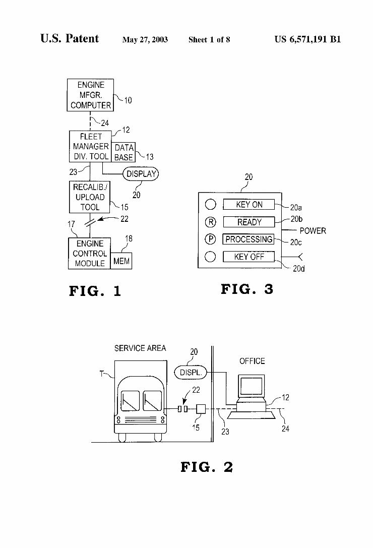
FIG. 1 is a schematic representation of a system for recalibration of an engine control module in accordance With one embodiment of the present invention.
FIG. 2 is a pictorial representation of the environment in Which the system shoWn in FIG. 1 is used.
FIG. 3 is a front elevational vieW of a display used in the environment shoWn in FIG. 2.
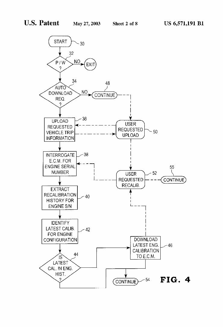
FIG. 4 a How chart of steps of one method for recalibra tion of an engine control module in accordance With one embodiment of the present invention.
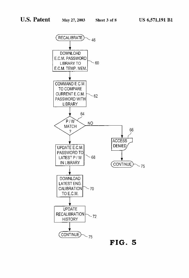
FIG. 5 is a How chart of steps for doWnloading engine recalibration information to an ECM forming part of the method shoWn in FIG. 4.
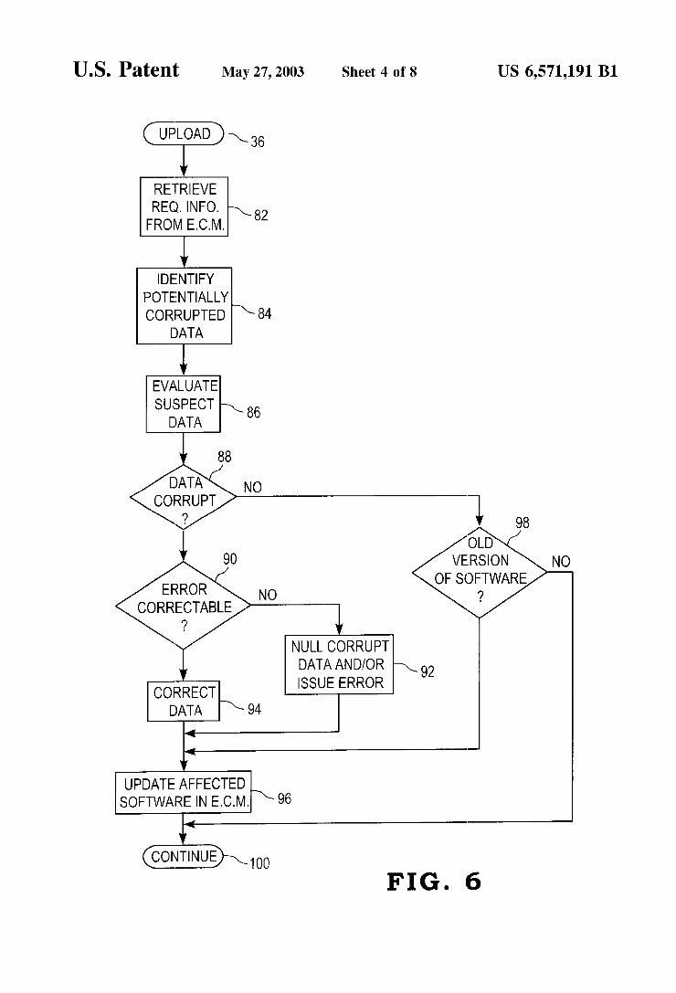
FIG. 6 is a How chart shoWing steps for uploading trip information implemented by the method shoWn in the How chart of FIG. 4.
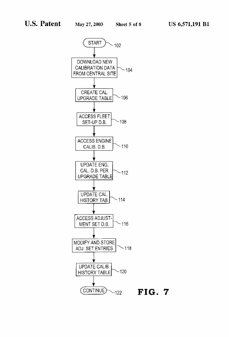
FIG. 7 is a How chart of steps for generating engine recalibration data.
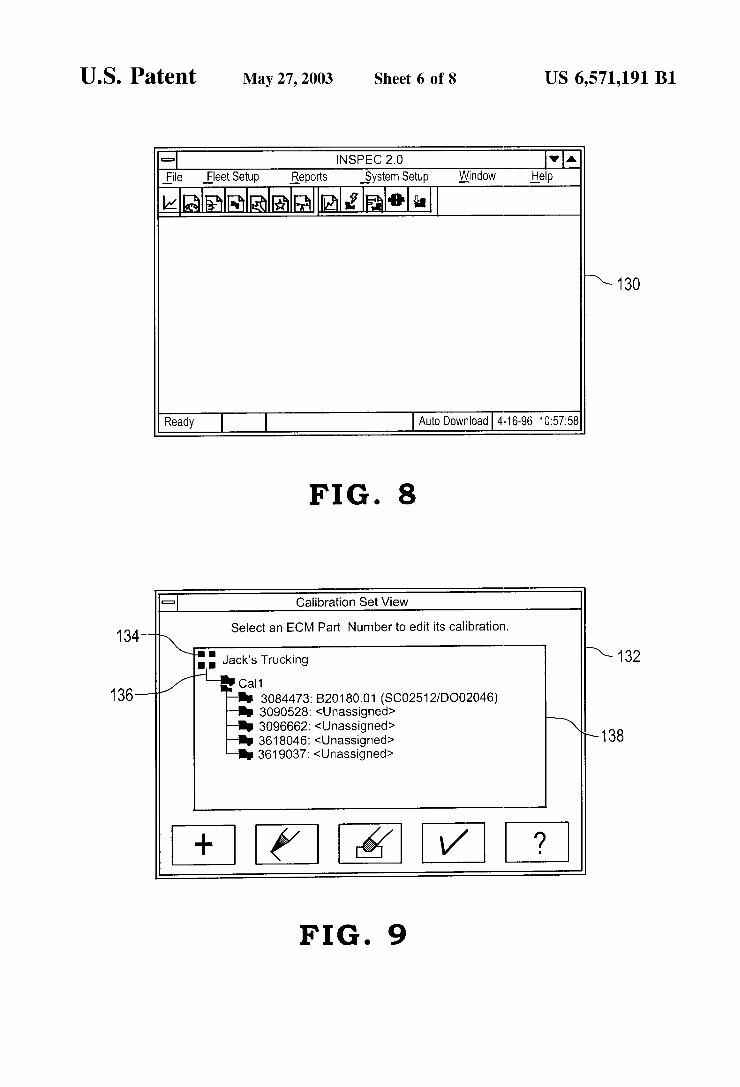
FIG. 8 is a pictorial representation of a screen display for a WindoWsTM-based softWare routine implementing the steps shoWn in the How charts of FIGS. 4—7.
FIG. 9 is a pictorial representation of a further screen display identifying a hierarchy of engine calibration sets.
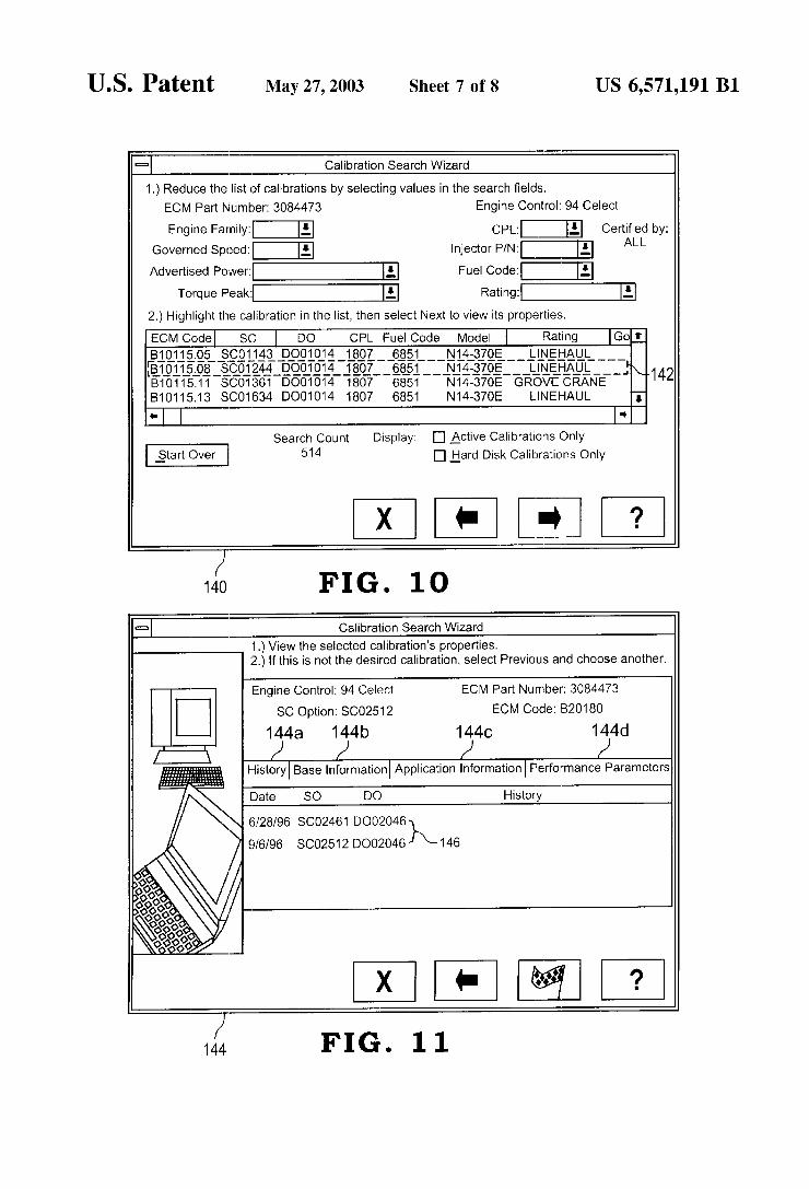
FIG. 10 is a pictorial representation of a screen display generated by the program identi?ed With respect to FIG. 8, in Which the screen display illustrates an array of calibration selections.
15
25
35
45
55
65
4 FIG. 11 is a pictorial representation of a screen display for
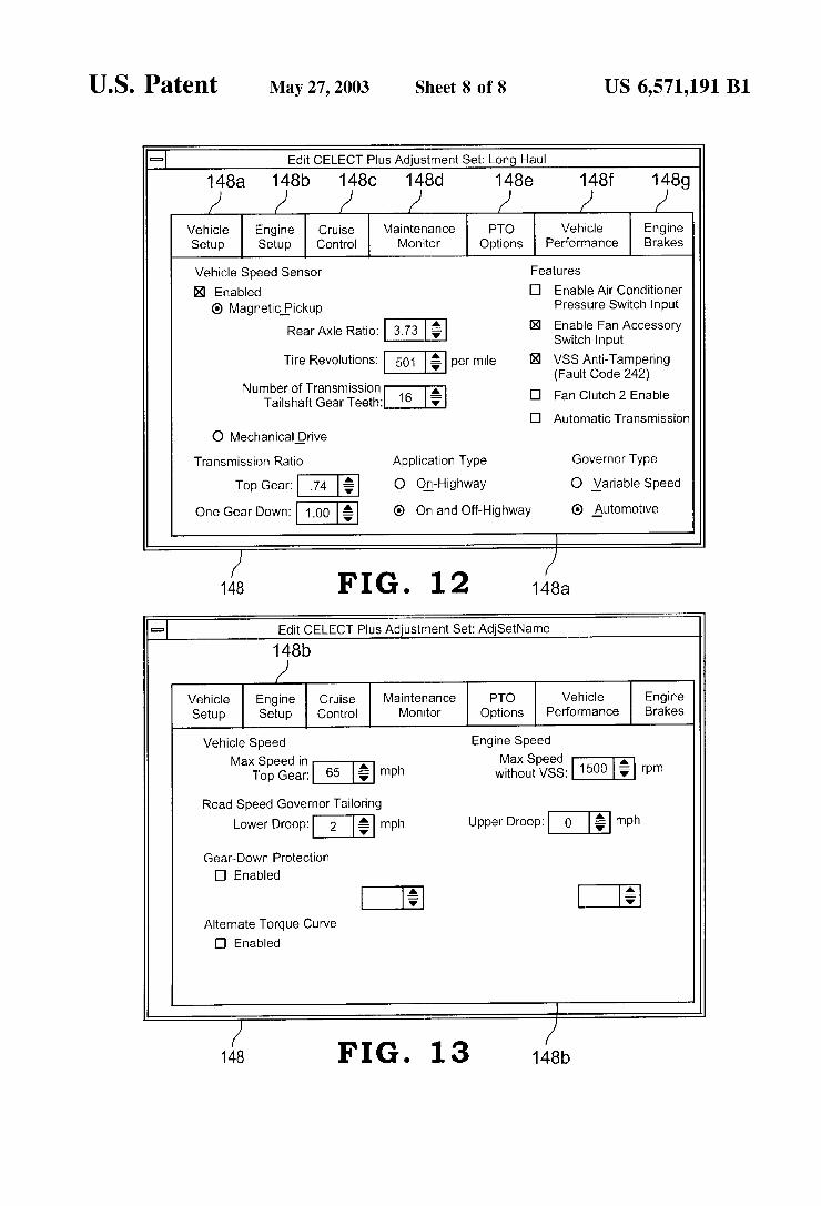
speci?c information concerning an engine calibration. FIG. 12 is a pictorial representation of screen displays for
de?ning adjustment sets to be used With the system depicted in the How charts of FIGS. 4—7.
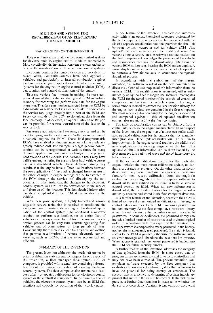
FIG. 13 is a pictorial representation of screen displays for de?ning adjustment sets to be used With the system depicted in the How charts of FIGS. 4—7.
DESCRIPTION OF THE PREFERRED EMBODIMENTS
For the purposes of promoting an understanding of the principles of the invention, reference Will noW be made to preferred embodiments illustrated in the draWings and spe ci?c language Will be used to describe the same. It Will nevertheless be understood that no limitation of the scope of the invention is thereby intended, such alterations and fur ther modi?cations in the illustrated embodiments, and such further applications of the principles of the invention as illustrated therein being contemplated as Would normally occur to one skilled in the art to Which the invention relates. The present invention contemplates a system and method
for recalibration of an electronic control system, such as an engine control module (ECM). In particular, the invention facilitates automation of the recalibration process, including security authoriZation checks and data integrity checks.
In one embodiment of the invention, a computer 10 at central location, such as an engine manufacturer’s site, is used to generate calibration data for a variety of engines and/or engine applications. For example, a typical engine manufacturer Will produce tWo or more models of internal combustion engines. Each model of engine typically requires a different set of calibrations that control the intake of fuel and air, the combustion timing and other performance aspects of the engine. Each engine may also have different data generation and report generation capabilities. In addi tion to the many engine models, an engine manufacturer Will generally provide the engines for use in a Wide range of applications. For example, the same engine can be used in a long-haul or line-haul truck, a ?re engine, an off-road construction vehicle, and many other heavy and light duty applications. For each application, the engine may require a different calibration or a different set of trip data. Consequently, engine manufacturers typically generate a selection of engine calibrations to be provided to end-users of the particular engine. As shoWn in FIG. 1, one end user is a ?eet manager Who
oWns and operates a ?eet of vehicles, for example, using the engine manufacturer’s engines. In accordance With the invention, the ?eet manager has a development tool 12 that is usually a personal computer having an on-board memory storing a database 13 of information concerning the engines. Typically, the ?eet manager uses development tool 12 to receive information concerning the performance of the engines in the vehicles of the managed ?eet. In accordance With the present invention, developmental tool 12 also enables the ?eet manager to recalibrate the engines of certain vehicles, either automatically or With human inter vention.
In certain embodiments, this recalibration occurs through the use of a recalibration or upload tool 15. Frequently, this tool is a hand-held apparatus that can transmit and receive information to and from engine control module 17. Engine control module 17 is situated Within the particular vehicle. ECM 17 also includes a memory 18 that can store data accumulated from various engine sensors, as Well as pro grams and associated data for controlling the function, and therefore the calibration, of the engine. The various components of this system shoWn in FIG. 1
can communicate With other components in a variety of
US 6,571,191 B1 5
Ways. For example, data can be transmitted from recalibra tion tool 15 to engine control module 17 through a data link 22. Data link 22 can be a variety of types, such as an SAE] 1708 or SAE] 1939 link. Recalibration tool 15 can include a cable, Which is plugged into ECM 17. Alternatively, and preferably, data link 22 is a Wireless link requiring only that the vehicle T (see FIG. 2) be aligned With recalibration tool 15.
Data from development tool 12 can be transmitted to recalibration tool 15 over a link 23. Again, link 23 can be of a variety of types. In one embodiment, development tool 12 and recalibration tool 15 are essentially part of the same device. In this instance, data link 22 can be connected to a serial port of developmental tool computer 12 (see FIG. 2). As shoWn in FIG. 2, developmental tool computer 12 also operates a display 20 that is disposed Within the service area in Which vehicle T is situated during the upload/doWnload process. In accordance With one embodiment of the present invention, ?eet computer 12 controls display 20 to provide the driver of vehicle T With certain information related to the doWnload/upload process.
The ?nal link of the components of the system shoWn in FIG. 1 is data link 24 betWeen engine manufacturer com puter 10 and ?eet manager computer 12. This data link 24 can be a variety of types of communication links, such as the SAE] 1708 and SAE] 1939 links discussed above. Data link 24 can also be in the form of a dial-up link, such as communications through the internet, in Which information can be accessed at engine manufacturer computer 10 and doWnloaded to ?eet computer 12. Finally, data link 24 also contemplates transferring information through hard media, such as a CD-ROM or ?oppy disk. The information obtained from engine manufacturer computer 10 can be the variety of engine calibrations established by the engine manufacturer.
In accordance With the system and method of the present invention, a vehicle, such as truck T, enters a service area as shoWn in FIG. 2. Data link 22 is established betWeen the ECM onboard the truck T and recalibration tool 15. In the illustrated embodiment, this recalibration tool is linked to of?ce computer 12 of the ?eet manager. This office computer includes a database 13 that contains the engine recalibration information previously doWnloaded from the engine manu facturer. In one embodiment of the invention, ?eet manager computer 12 controls a display 20 to instruct the driver of the truck T as to the necessary steps for the doWnload and upload aspects of the invention. One type of display as shoWn in FIG. 3 Which includes an array of visual annun ciators 20a—20a'. As shoWn in FIG. 3, display 20 directs the vehicle operator to turn the ignition key on or off, depending upon the step in the processing of information transferred to and from the engine control module. Processing annunciator 20c indicates that the data doWnload and upload is occurring, While the ready annunciator 20b tells the truck operator that the process is complete.
In accordance With the present invention, ?eet develop ment computer 12 is loaded With softWare that automates the doWnload of trip information from the vehicle ECM 17, and the upload of recalibration information to ECM 17. For this purpose, computer 12 preferably includes an IntelTM 386 processor or better, about 32 megabytes of random access memory (RAM), a WindoWsTM operating system, at least one available parallel port, and at least one available serial port for data communication. Aprogram can be loaded onto computer 12 that can be initiated manually or left in an idle state until initiated by an external trigger. In one speci?c embodiment, the program remains resident and idle on ?eet computer 12 until a truck T enters the service area. At that point, a signal from ECM 17 or recalibration tool 15 can alert ?eet computer 12 to the arrival of a vehicle T.
It is at this point that the softWare steps of the ?oW chart of FIG. 4 are instituted. After starting step 30 in Which the
10
15
25
45
55
65
6 computer is aWakened from its idle mode, a determination can be made in conditional step 32 Whether the proper passWord has been entered by the user of ?eet computer 12. If not, then the program automatically exits, since the user is not permitted access to upload or doWnload information to and from ECM 17.
If the proper user passWord is entered, control passes to conditional step 34. In accordance With one aspect of the present invention, the softWare routine implemented by ?eet computer 12 is capable of automatically conducting data doWnload and upload steps. In conditional step 34 it is ascertained Whether the program has been directed to con duct the steps of the method automatically Without user intervention. If so, then control passes to step 36 in Which vehicle trip information is uploaded that has been requested by the ?eet manager. In one aspect of the invention, ECM 17 and particularly memory 18 contains data related to the performance of the engine since the last doWnload. This data can be doWnloaded from the ECM and stored in database 13 of ?eet computer 12 for subsequent evaluation and manipu lation by the ?eet manager. Preferably, the program imple menting the steps of the ?oW chart shoWn in FIG. 4 also includes various report generation modules that alloWs the ?eet manager to digest the doWnloaded trip information and generate various reports and charts indicative of the perfor mance of the particular engine and of the ?eet overall.
Once the requested information has been uploaded to ?eet computer 12, the next feW steps are implemented to doWn load engine recalibration information to ECM 17. In ?rst step 38, the ECM is interrogated to determine the serial number of the engine Within Which the ECM is installed. Each engine produced by the manufacturer is given a unique engine serial number that distinguishes it from all other engines. The serial number can be loaded in memory 18 of ECM 17 for subsequent access, preferably, the serial number is loaded into the ECM at the engine manufacturer’s location, although that serial number can be stored in the ECM memory using recalibration tool 15 under certain circumstances. Armed With the engine serial number, the softWare ?oWs
to the next step 40 in Which the recalibration history of the particular engine is extracted. Preferably, database 13 of ?eet computer 12 maintains a complete history of the various calibrations applied to all of the engines Within the vehicle ?eet. The recalibration history can include entries for various softWare adjustments to the ECM control softWare, modi?cations to fuel injector parameters, and even adjust ments to engine condition monitors and sensors. Preferably, database 13 maintains the recalibration history in date order, namely that the database contains an entry for the date of the recalibration as Well as the particular recalibration event. In the next step 42, the latest calibration information is iden ti?ed Within the recalibration history. In a speci?c embodiment, this step 42 simply entails ?nding the latest date for recalibrations Within the history extracted in step 40. In the preferred embodiment, the recalibration history for each engine serial number is maintained in ?eet computer 12. Alternatively, ECM 17 itself can store the recalibration history for the particular ECM. In this latter case, the engine recalibration history information can be uploaded from the ECM to ?eet computer 12.
In the next step 44, a determination is made as to Whether the particular engine has been provided With the latest calibration information. Fleet computer 12 maintains a table in database 13 containing the most recent engine/ECM recalibration information. This table can be created by the ?eet manager at ?eet computer 12, or it can be doWnloaded from engine manufacturer computer 10 in the various man ners set forth above. For example, if the most recent reca libration involves modifying the data uplink capability of the
US 6,571,191 B1 7
ECM, the table Within ?eet computer 12 Will identify this change and the corresponding date of the change. Condi tional step 44 involves comparing this most recent recali bration information With the latest calibration extracted from the engine recalibration history. If the engine recalibration history reveals that the latest calibration has been implemented, the program exits the upload/doWnload steps and continues at step 54 to other portions of the softWare routine. HoWever, if the latest calibration information in the recalibration history does not match the latest calibration entry in the table maintained in ?eet computer 12, control passes to step 46. In this step, engine/ECM calibration information is doWnloaded from ?eet computer 12 to ECM 17. This doWnloading can occur directly betWeen computer 12 and ECM, or can occur through recalibration tool 15 as described above.
In accordance With the illustrated embodiments, the reca libration of the ECM can occur according to a variety of protocols. In some cases, the recalibration simply involves modifying various constants that are read by engine control subroutines. In other cases, the calibration information involves modi?cations to existing softWare modules or the addition of neW softWare modules to perform further moni toring or controlling functions. Any knoWn means of doWn loading calibration and recalibration information to an ECM is contemplated to satisfy doWnload step 46 of the present invention. Once the latest engine/ECM calibration informa tion has been doWnloaded, the program continues at step 54.
Referring back to conditional step 34 in the ?oW chart of FIG. 4, if an automatic doWnload has not been requested, the program ?oW can continue at step 48. At this step, the program can pass to other subroutines of the program being executed by ?eet computer 12. Alternatively, the program also provides means for user requested data upload or recalibration. For example, in step 50, if the ?eet manager requests an upload of vehicle trip information from the vehicle T, the subroutine of step 50 directs control to step 36 to upload the requested information and then return to subroutine 50. Likewise, in the subroutine of step 52, the ?eet manager can directly request recalibration of the ECM of the truck T left in the service area. In this instance, the program ?oW passes to step 38 and continues to step 46, after Which control returns to subroutine 52. Once the latest engine/ECM recalibration data has been doWnloaded, con trol passes to step 55 to continue With other portions of the softWare. As illustrated in FIG. 4, the present invention contem
plates a system for automatically determining Whether ECM 17 of a particular vehicle T requires recalibration. With this feature, a vehicle can be constantly and readily monitored When pulling into a particular service area. It is contem plated that a vehicle ?eet can include a number of service areas throughout the ?eet operating range. In this instance, it may be more economical to utiliZe separate recalibration tools 15 at each service area rather than to provide a ?eet manager development tool 12 at each site. In this instance, recalibration tool 15 can include its oWn memory to receive data from ?eet computer 12. Alternatively, recalibration tool. 15 can be connected as a remote device With ?eet tool 12, With its operation being directed by the ?eet computer. HoWever, most preferably, each service area includes its oWn ?eet computer 12 that can direct the recalibration tool 15 as Well as display 20. As mentioned above, the softWare implemented by ?eet
computer 12 can be continuously running. Ideally, the softWare can enter a sleep mode When no vehicle is in the service area. Once the vehicle T enters the service area, the program can be aWakened and prompted to commence the steps as shoWn in the ?oW chart of FIG. 4.
Thus, With the present invention, the vehicle operator can be assured that the ECM of the vehicle T Will alWays have
10
15
25
35
45
55
65
8 the most recent engine/ECM calibration data. The recalibra tion history for the particular engine serial number can be readily maintained in hard disk memory of ?eet computer 12. Each time the ECM of the vehicle T is recalibrated, a neW entry is made in the stored recalibration history. Typically, the ECM for a given vehicle T Will not require calibration. From the point of vieW of the present invention, this means that the latest calibration in the table of neW calibration information obtained from the central site Will be the same as the most recent calibration maintained in the calibration history of ?eet computer 12. HoWever, even though the engine ECM is not recalibrated, the routine shoWn in FIG. 4 Will still upload requested vehicle trip information of ECM 17 of the truck T to ?eet computer 12.
In a further re?nement of the present invention, the recalibration of the ECM includes security authentication/ veri?cation checks to ensure that the electronic control system, such as ECM 17, is not subject to unauthoriZed recalibration. In most engine control modules, a speci?c passWord is required to gain access to the control routines and data of the ECM. As With most security systems, the ECM’s access passWords are changed on a regular basis to reduce the likelihood of tampering. HoWever, in certain vehicle applications, the vehicle may not enter a service area for quite a While. During that time, the operative passWord may have changed several times. In that case, issuance of the most recent passWord Will not permit access to the ECM of a long overdue vehicle.
This problem is solved in accordance With the present invention by the provision of a passWord library. This feature of the invention can be implemented in one embodi ment according to the steps shoWn in the ?oW chart of FIG. 5. Preferably, these steps form part of a recalibration sub routine that is conducted at step 46 of the ?oW chart shoWn in FIG. 4. When a decision is made to doWnload, the latest engine calibration dated to the ECM in step 46, the ECM passWord library is ?rst doWnloaded in step 60 from ?eet computer 12 to the ECM memory 18. In a typical instance, this passWord library Would simply contain a list of the most recently used passWords, or the passWords used over a predetermined period of time. In that latter case the period of time can be three months, for example, Which may entail tWelve different passWords if the passWords are changed every Week.
Once the passWord library has been doWnloaded to the ECM in step 60, a command is issued to the ECM to compare the current passWords already stored Within the ECM to each of the passWords Within the recently doWn loaded passWord library. This comparison can involve a one-to-one comparison until a match is found.
In the embodiment illustrated in FIG. 5, it is assumed that all of the passWord veri?cation steps Would be conducted by the ECM. HoWever, the same steps can be conducted by ?eet computer 12, or even recalibration tool 15. In this instance, step 60 can be modi?ed since there Would be no need to doWnload the passWord library to the ECM temporary memory. In this instance, step 60 Would involve uploading of the ECM passWord from its memory 18 to the temporary memory, or a ?ash memory, of the recalibration tool or ?eet tool 12. A?ash memory is preferred because it can be readily erased. Step 62 Would be modi?ed to simply conduct the comparison Within the recalibration tool or ?eet computer, rather than to direct the ECM to make the comparison. Since it is desired to prevent unauthoriZed modi?cation of the ECM for a particular vehicle, safeguards must be instituted in the event that the ECM passWord is uploaded from the ECM to a separate computer. In this instance, the ?oW chart of FIG. 5 can be modi?ed to include a step in Which the ?ash memory is erased to ensure that the ECM passWord is eliminated from the local computer, especially if no pass Word match is found.
US 6,571,191 B1
In conditional step 64, it is determined Whether the existing ECM password matches any one of the passwords Within the passWord library. If not, then an “access denied” message is provided in step 66 and the program ?oW continues at step 75. On the other hand, if the current passWord Within the
ECM matches any one of the passWords Within the library, control passes to step 68. In this step, the neWest passWord from the passWord library is doWnloaded to the ECM. The then existing ECM passWord is removed and replaced by this latest passWord. In this Way, the passWord of the ECM is being constantly and automatically updated. This elimi nates the need for the ?eet manager or the vehicle operator to knoW the particular passWord for ECM 17.
Once the passWord resident With the ECM has been updated in step 68, the engine/ECM calibration information is doWnloaded in step 70 and the recalibration history for the particular engine is updated in step 72. The program ?oW continues to other subroutines at step 75. As suggested above, the passWord library can consist
simply of a list of most recently used passWords. In accor dance With the present invention, the list must contain at least tWo passWords, namely the most recent passWord and the next most recent passWord. In this circumstance, all vehicles of the ?eet Will have either one of the tWo pass Words resident Within its ECM. Vehicles that have the next most recent passWord Will eventually require updating to the most recent passWord Within the library.
In cases Where the vehicles T are frequently in the service area (FIG. 2) the tWo passWord list may be suf?cient. HoWever, in cases Where the vehicles Will not be serviced as regularly, a longer passWord library is essential. A speci?c protocol can be adopted for truncated the passWord library. For example, as suggested above, a particular passWord can be maintained Within the library for a predetermined period of time, such as three months. After three months has expired, the passWord is erased from the library. A vehicle having a passWord that does not match one of the library entries can be ?agged for detailed inspection by the ?eet manager. In this Way, the passWord library and security routine of FIG. 5 can be used to determine Whether a vehicle operator has folloWed a required service regiment. Avehicle With an ECM having an outdated passWord is automatically suspect and triggered by the routine according to the present invention. A further feature of the present invention is implemented
in the uploading of vehicle trip information from an ECM to ?eet computer 12. Thus, step 36 shoWn in FIG. 4 can be implemented by the subroutines shoWn in ?oW chart of FIG. 6. As shoWn in this ?oW chart, once an upload request has occurred, the identi?ed information is retrieved from the ECM in step 82. This data upload can occur in a conven tional manner over data links 22 and/or 23 to ?eet computer 12. In the next step 84, the uploaded data is evaluated to determine if it contains potentially corrupted data. In this step, ?eet computer 12 contains a database of vehicle trip information that is knoWn to have some problem associated With it. For instance, it may be knoWn that a prior version of data-gathering softWare resident Within an ECM failed to reset the fuel usage counter so that any collected trip mileage information Would be incorrect or corrupt. The trip mileage and fuel usage data can be ?agged as potentially corrupted, and this ?ag maintained Within ?eet computer 12. In step 84, the speci?cally ?agged data can be picked out of the information uploaded from the ECM.
In the next step 86, this suspect data is evaluated to determine Whether it is corrupted or legitimate. The evalu ation in step 86 can entail a variety of steps, depending upon the nature of the suspect data. In the speci?c given example, the trip mileage data can be compared to the fuel usage
10
15
25
35
45
55
65
10 counter based upon an assumed vehicle mileage rate. An estimated fuel usage can be determined using the trip mileage and vehicle mileage rate. If the actual fuel usage is far different from the estimated usage, the suspect data can be identi?ed as corrupt or as having been generated by the incorrect softWare routine. Other suspect data Will require different types of evaluation and comparison. The database of potentially corrupted data can also include the particular evaluation protocols to determine Whether the suspect data is actually corrupted.
Depending upon the outcome of the evaluation of step 86, is it determined Whether the data is corrupt or not in conditional step 88. If the data is corrupt, then the next conditional step 99 determines Whether the error is correct able. For example, in some cases the data error can be corrected using other data that is not knoWn to be inaccurate or corrupt. In the illustrated example, the incorrect fuel usage counter can be corrected based upon the trip mileage and estimated vehicle mileage. On the other hand, certain errors cannot be corrected. One example can be exhaust manifold data that is incorrect and cannot be calculated using other sensor values. Whether or not the particular error is correctable can also be maintained in the database con cerning the potentially corrupted data. Adatabase ?ag can be set if the error can be corrected. If the error cannot be corrected, the program ?oWs to step 92 in Which the cor rupted data can be nulled and/or an error message issued to alert the ?eet manager to the problem.
If the corrupt data listing indicates that the error is correctable, the ?x can also be maintained in the database. For correctable errors, the data is ?xed in step 94. Regardless of Whether the error in the data is correctable, the effected softWare in the ECM is updated in step 96 to eliminate the occurrence of these errors in future trip information uploads. Returning to conditional step 88, if the data is determined not to be corrupt, a further conditional step 98 is conducted to determine Whether the suspect softWare Within the ECM is of the older version or not. If the ansWer to conditional in step 98 is yes, the softWare is updated in step 96, if not, then the program control passes to the continuation in step 100. The ?eet manager uses the developmental tool or com
puter 12 to assess recent re-calibration data and generate data for additional adjustments. Referring to FIG. 7, a ?oW chart of general administrative steps conducted by the program in the ?eet computer 12 is shoWn. The starting step 102 can occur at any time during the operation of the program. Since it is envisioned that the ?eet computer 12 may be constantly monitoring the service area for the arrival of a vehicle T, the ?eet manager Would typically perform these general administrative steps after a vehicle has been processed, or during “off hours”. A ?rst part of the admin istrative tasks is to doWnload neW calibration data from the central location in step 104. As shoWn in FIG. 1, the central location can be the engine manufacturer’s computer 10. HoWever, it is contemplated that the present invention can be applied to other electric controls. For instance, in certain vehicles the transmission itself is electronically control similarly, various other mobile equipments, such as a refrig eration unit, may also have an electronic controller that requires upgraded calibrations. Thus, in the step 104, the ?eet manager can access the neW calibration data from the appropriate central site. As indicted above, this doWnload process can occur over a data line, through the Internet, or directly from a computer disk.
In the next step 106, the program creates a calibration upgrade table that is referenced during the re-calibration steps depicted in FIGS. 4 and 5. It is contemplated that the calibration upgrade table Will identify the particular elec tronic controller, the date of the calibration, the nature of the re-calibration, and the data necessary to perform the re-calibration.
US 6,571,191 B1 11
In one speci?c embodiment, the ?eet manager can the access a ?eet set up database in step 108. The ?eet setup database includes information for all electronically con trolled components Within the ?eet. For example, a speci?c ?eet may include a plurality of line haul trucks, each having an electronically controlled engine. The ?eet may also have a variety of different application vehicles as discussed more fully above. Once the ?eet manager opens the ?eet set up database, access can be provided to an engine calibration database 110. It is understood that the speci?c illustrated embodiments involve an ECM, so that an engine calibration database Would be maintained at the ?eet computer 12. Alternatively, or in addition, other calibration databases can be provided for additional electronically controlled components, such as the transmission mentioned above. Depending upon the nature of the neW calibration data, the ?eet manager Would access the appropriate calibration data base. For purposes of illustration, step 110 involves access ing the engine calibration database only.
Once the engine calibration database for the ?eet has been opened, the database entries are upgraded pursuant to the calibration upgrade table created from the doWnloaded cali bration data. This engine calibration database is used in the recalibration steps shoWn in FIGS. 4 and 5. In order to complete the preparation for doWnloading the neW calibra tion data, the calibration history table for each particular engine or electronic control module is updated. It may be recalled that the calibration history table is the vehicle by Which a determination is made as to Whether the ECM of the truck T in the service area requires recalibration.
Certain factory-endorsed recalibrations may require adjustments of other related components of the vehicle. For eXample, certain aspects of the vehicle or engine setup may require modi?cation When an engine is recalibrated. The present invention contemplates that the illustrated program permits the ?eet manager to create an adjustment set data base. The adjustment set database can include entries for all of the vehicles in the ?eet With the particular adjustment data associated With that vehicle. The adjustment set database can include entries that simply effect the collection of trip information for the vehicle. In addition, the adjustment set database can include entries that speci?cally modify the vehicle or engine performance. In the former case, types of adjustment set information that effects the collection of trip information may include the rear aXle ratio for the vehicles speed sensor or the top gear ratio for the transmission. Vehicle performance related information could include a cruise control speed limit setting that restricts the vehicle operators ability to set the cruise control operation.
Referring back to FIG. 7, the ?eet manager can access the adjustment set database in step 116 for the particular ?eet database opened in step 108. In step 118, various adjust ments set entries can be modi?ed or neW entries stored. The effected adjustment set entries can be based an evaluation of the neW calibration data presented by the engine manufac turer for eXample. In some cases, the engine manufacturer may provide additional speci?cation information suggesting certain adjustment set modi?cations. Once the adjustment set has been upgraded in step 118, the calibration history table is also updated in step 120 to re?ect these modi?ca tions. It is contemplated that a particular vehicle may only have modi?cations its adjustment set, Without commensu rate route changes to its calibration information. HoWever, in the most instances, modi?cations to the adjustment set information Will accompany recalibration data. Once all of these steps have been completed, the various databases can be closed and the program directed to continue its monitor ing function in step 122.
Referring noW to FIGS. 8—13, various screen displays are shoWn that can be implemented by a program in accordance
15
25
35
45
55
65
12 With certain embodiment of the present invention. In FIG. 8, a main screen display 130 is shoWn. Various pull-doWn menus can be identi?ed, such as “Fleet Set Up”. The steps depicted in the ?oW chart of FIG. 7 can be initiated by pulling doWn the “Fleet Set Up” menu Which can include speci?c instructions for doWnloading calibration data, accessing the ?eet set up database and/or accessing and modifying the calibration database or adjustment set entries. The main screen 130 can also include a variety of icons for performing various administrative and report generating functions.
In step 110 of the ?oW chart in FIG. 7, the engine calibration database is opened by the ?eet manager. FIG. 9 shoWs one type of screen display that can be created When the engine calibration database is accessed. As shoWn in FIG. 9, the calibration set screen 132 can include a ?eet identi?er 134 that identi?es a particular ?eet being managed. It is contemplated that a single ?eet manager may control several different ?eets, or may Want to segment one ?eet into a number of sub-?eets. An additional entry in the calibration set screen 132 is a calibration identi?er 136. For each ?eet, the manager can provide a variety of calibration sets. In a speci?c embodiment, each calibration set includes ?ve spe ci?c electronic controllers in the group. For eXample, one electronic controller, or ECM, as a part number 3084473, as noW depicted in the entry 138. Each ECM part number in a calibration set can be associated With a particular calibration set, as identi?ed With the pre?X B for entry 138. Each calibration set can be associated With a particular softWare change code (the pre?X “SC”), or a dashboard option (the pre?X “DO”). Of course, other methods for identifying particular calibrations and associating those calibrations With a speci?c ECM or electronic controller serial number are contemplated. It Will be noted that some of the ECM part numbers do not have any calibrations assigned. These ECM’s can simply include the factory installed calibration, or can constitute ECM’s that are not presently in vehicles.
Referring noW to FIG. 10, the neXt screen in the sequence of operation of the softWare is shoWn. In accordance With one speci?c embodiment, the screen display of FIG. 10 is accessed by clicking on one of the ECM calibration entries 138. The screen display 140 in FIG. 10 is a calibration search screen that permits the ?eet manager to revieW all of the calibration entries in the eXisting database. The calibration search “Wizard” alloWs the ?eet manager to select a par ticular calibration based upon a variety of different entries. Once a calibration is chosen, such as the identi?ed calibra tion entry 142, the ?eet manager can direct that this cali bration be assigned to a particular ECM part number. In accordance With one aspect of the invention, once a calibration, such as entry 142, is directed to be assigned to an ECM part number, it is determined Whether that particular calibration has itself been updated by the engine manufac turer. If so, the softWare directs that the upgrade calibration be substituted for the requested calibration, and then assigned to the particular ECM serial number. As a further aspect of the illustrated embodiment, the
calibration search “Wizard” alloWs the ?eet manager to vieW various characteristics for each calibration, such as entry 142. A screen display 144, as shoWn in FIG. 11, includes a number of tabs at 144a—144a', that can be accessed by the ?eet manager. The history tab 144a can be accessed to reveal the calibration history for the particular calibration, as denoted by the entries 146 in FIG. 11. The other tabs reveal additional speci?c information about each calibration. As described in connection With FIG. 7, the ?eet manager
also has the opportunity to modify certain adjustment sets that effect the performance and/or trip information collection process for a particular engine and/or vehicle. TWo such screen displays are shoWn in FIGS. 12 and 13. Screen
US 6,571,191 B1 13
display 148 shows one screen of an adjustment set display. This screen includes a number of tabs 148a—148g that can be accessed by the ?eet manager to change various pieces of adjustment data. For example, the screen 148a is accessed for viewing speci?c vehicle set up adjustments. As shoWn in FIG. 12, the vehicle set up information can include details about the vehicle’s speed sensor, transmission ratio and other speci?c features of the vehicle. Looking noW at FIG. 13, the engine set up screen 148B is shoWn. In this screen, the ?eet manager can make adjustments to entries such as the vehicle maX speed and top gear. The remaining tabs 148c—148g include similar adjustment data for use of modi fying the performance and action of the vehicle and/or engine.
While the invention has been illustrated and described in detail in the draWings and foregoing description, the same is to be considered as illustrative and not restrictive in char acter. It should be understood that only the preferred embodiments have been shoWn and described and that all changes and modi?cations that come Within the spirit of the invention are desired to be protected. What is claimed is: 1. A method for recalibration of a remote electronic
control system by a computer separate from the remote electronic control system, comprising the steps of:
transmitting an initiation signal from the remote elec tronic control system to the computer;
developing a history of recalibrations for the remote electronic control system;
accessing a most recent calibration to be applied to the remote electronic control system;
determining by the computer Whether the recalibration history includes the most recent calibration; and
if not, recalibrating by the computer the remote electronic control system according to the most recent calibration and updating the recalibration history to include the most recent calibration;
Wherein the determining and recalibrating steps are con ducted in response to receipt by the computer of the initiation signal.
2. The method for recalibration according to claim 1, further comprising:
assigning a unique serial number to the electronic control system; and
Wherein the steps of developing a recalibration history and accessing a most recent calibration are correlated to each serial number.
3. The method for recalibration according to claim 1, Wherein the step of accessing a most recent calibration
15
25
35
45
14 includes doWnloading calibration information from a central site remote from the computer and from the remote elec tronic control system.
4. The method for recalibration according to claim 1, further comprising the steps of:
assigning an access passWord to the remote electronic control system;
maintaining a passWord library of acceptable passWords in a media separate from the remote electronic control system;
prior to the step of recalibrating, comparing the access passWord to entries in the passWord library of accept able passWords and initiating the recalibration only if the access passWord matches an entry in the passWord library of acceptable passWords.
5. The method for recalibration according to claim 4, further comprising the steps of:
determining the most recent entry in the passWord library of acceptable passWords; and
updating the access passWord to the most recent entry if the access passWord matches an entry in the passWord library of acceptable passWords.
6. A method for ensuring data integrity for data retrieved from a remote electronic control system comprising the steps of:
generating data With control routines in the remote elec tronic control system;
independent of the remote electronic control system, identifying types of data that may be corrupted When generated by the control routines;
retrieving the data generated by the remote electronic control system;
determining if the identi?ed types of data are present in the retrieved data; and
instituting an error correction procedure if the identi?ed types of data are present.
7. The method for ensuring data integrity according to claim 6, Wherein the step of instituting an error correction procedure includes:
identifying a subset of the identi?ed types of data that can be corrected;
determining if the identi?ed types of data present in the retrieved data correspond to the identi?ed subset; and
if so, correcting the identi?ed types of data in the retrieved data.