metal matrix - solid lubricant composites
DESCRIPTION
Metal Matrix - Solid Lubricant CompositesTRANSCRIPT

METAL MATRIX—SOLID LUBRICANT COMPOSITES
Pradeep K. Rohatgi Subrat Ray, and Yongbing Liu
INTRODUCTION
Solid lubrication is observed in solids with lower shear strength between certain planesresulting in easy movement along these planes and reduced friction and wear. Most solidlubricants are therefore the layer-lattice or lamellar solids such as graphite and molybdenumdisulfide, containing weakly bonded layers which facilitate relative movement under shear.1
In composites, solid lubricants are embedded in the matrix as a constituent. The frictionand wear of metal matrix solid lubricant composites depend on smearing of solid lubricantson the mating surfaces to form a lubricating film. The lubricating film forms by transfer oflubricating constituent on the mating surface. The adhesion of solid lubricant to the underlyingsurface is an important factor for smearing. The tribological behavior normally displays twodistinct stages, (a) an initial transient state while the film is forming, and (b) steady state whena stable film has formed.
SYNTHESIS OF METAL MATRIX—SOLID LUBRICANTCOMPOSITES
Table 1 lists selected solid lubricants incorporated in metal matrix composites. Coefficientof friction of these lubricants is around 0.1 to 0.25. The lubricants commonly employed atelevated temperatures, such as BN and CaF, have relatively higher coefficients of friction.
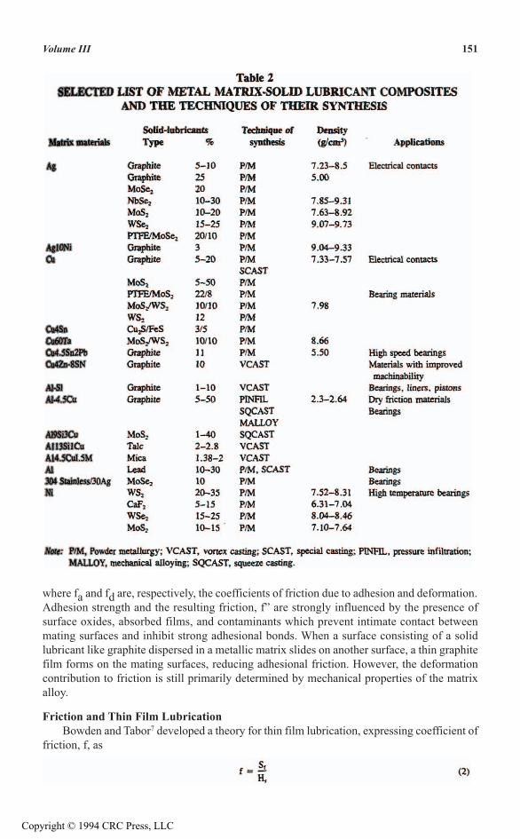
Generally, fabrication methods for metal matrix composites containing lubricatingparticles fall into three main categories: (a) powder metallurgy, (b) casting metallurgy, and (c)spray deposition. Table 2 lists selected composites prepared by different techniques.
Powder MetallurgyBasic manufacturing processes in powder metallurgy (P/M) include mixing, compacting,
and sintering of particulate raw materials. The mixing process is the important first step andcontrols the particle distribution in composites. Since the present state of the art of mixing byblending does not allow close control, segregation or clustering of particles is a commonproblem at this stage.
The primary reason for segregation is the different flow characteristics of differentpowders during mixing.2 The larger the particle size, generally the better will be the degree ofdistribution. Spherical particles mix better than irregular particles. Density difference alsoaffects the results of mixing two or more powders: light particles stay on top, while heavyparticles tend to sink to the bottom.
After mixing, powders are compacted in a die at pressures that make the particle adhereat contacting points. Sintering is the last manufacturing step, and control parameters in thisstage are the temperature and atmosphere. The primary problems in fabrication of metalgraphite composites by P/M are sweating during liquid phase sintering and poor strength insolid phase sintering. Sweating is commonly corrected by adding a small amount of calciumin the form of calcium-silicon alloy to the powder mixtures in iron-graphite systems, and thevolume fraction of graphite can then be increased even up to 90%.3 Techniques developed toincrease strength include mechanical alloying and sintering under pressure.2
CastingCasting offers a relatively low cost alternative to powder metallurgy techniques. Presently,
two casting methods are employed:4 (a) impregnation of a bed of dispersoids by liquid metal
1490-8493-3903-0/94/$0.00 + $0.50© 1994 by CRC Press, Inc.Copyright © 1994 CRC Press, LLC

or alloy under pressure in squeeze casting and pressure infiltration; and (b) dispersion of Iparticles or fibers in liquid or semisolid alloy by stirring, and the resulting slurry is cast by Igravity or pressure die casting. In squeeze casting, liquid metal is forced into a bed or apreform of particles or fibers under high pressure (70 to 100 MPa). In pressure infiltration, Imolten alloy is usually forced at low gas pressures of ≤15 MPa to flow into a compactedpreform or a bed in a tube and allowed to solidify. With this method, composites can beproduced with a high volume fraction of dispersoids.5 Infiltration pressure can also be appliedby a hydraulic ram in a die-casting machine.
Spray DepositionIn this method, liquid metal and dispersoid powders are co-sprayed through an atomizer
onto a substrate to form billet, disk, tube, strip, or laminated structures. Particles of 5 to 500µm size have been used with metal flow rates of 0.25 to 2.5 kg/s to produce composites with5 to 35 vol% particles.6 Aluminum, iron, nickel, titanium, copper, and cobalt base alloys havebeen used to produce metal matrix composites by this method.
THEORETICAL BASIS FOR UNDERSTANDING FRICTION ANDWEAR BEHAVIOR IN COMPOSITES
Even the most carefully prepared real surface is gently undulating and consists of manymicroscopic and macroscopic asperities. Friction between two solid surfaces arise frominteraction at discrete asperity sites where actual contact occurs. The basic processes involvedare (a) adhesion at the contacting points, and (b) deformation of asperities due to load. Toovercome friction, forces are required both to shear the adhesion bond, Fa, and also Fd toelastically or plastically deform obstructing asperities of the relatively softer material in thepath of asperities of the harder material. If N is the applied normal load on the contactingsurface, coefficient of friction f is given by7
150 CRC Handbook of Lubrication and Tribology
Copyright © 1994 CRC Press, LLC
where fa and fd are, respectively, the coefficients of friction due to adhesion and deformation.Adhesion strength and the resulting friction, f” are strongly influenced by the presence ofsurface oxides, absorbed films, and contaminants which prevent intimate contact betweenmating surfaces and inhibit strong adhesional bonds. When a surface consisting of a solidlubricant like graphite dispersed in a metallic matrix slides on another surface, a thin graphitefilm forms on the mating surfaces, reducing adhesional friction. However, the deformationcontribution to friction is still primarily determined by mechanical properties of the matrixalloy.
Friction and Thin Film LubricationBowden and Tabor7 developed a theory for thin film lubrication, expressing coefficient of
friction, f, as
151Volume III
Copyright © 1994 CRC Press, LLC

Low shear strength of the film on sliding surface, Sf, and a relatively high substrate hardness,Hs, then result in a low coefficient of friction, f. However, this simple picture fails to explainmany details in the complex frictional behavior of film-substrate combinations. Shear strengthof the film under pressure as proposed by Bridgeman8 is
152 CRC Handbook of Lubrication and Tribology
where α is a material constant and P is the normal pressure. Friction coefficient becomes
At low pressure, indentation of asperities of the mating surface may be confined withinthe film layer if the film is thick and the load will be supported by the film resulting in P = Hf,the hardness of the film. If the film is soft, coefficient of friction, f, will be higher due to highercontribution of the first term in Equation 4 because of low film hardness. But for a thin film,the indentation load will be supported by relatively hard substrate material and P = Hs resultingin a lower coefficient of friction. As the normal load increases, real area of contact increasesand becomes equal to the apparent area of contact. There will be no further increase in thisvariable. As pressure increases further, the first term in Equation 4 drops and, in the limitingcase of very high pressure, coefficient of friction approaches the value of α, a characteristicof the film material.
In the case of graphite bearing composites, the coefficient of friction both during run-inperiod and in steady state may be correlated approximately with the extent of film formationby the rule of mixture.
where fm and fg are, respectively, the friction coefficients in the exposed matrix area and inthe graphite film area. Ag is the fraction of composite sliding surface covered by graphitefilm. Following Equations 1 and 4:
and,
Thus, the coefficient of friction may vary from fm to fg, depending on composition of thecomposite and ability of the solid lubricant phase to spread over the matrix and counterface.
During initial sliding of composites, the solid lubricant comes out from its embedded stateand spreads over the sliding surface of the composite and/or transfers to the counterface. Theseprocesses continue, and rate of wear eventually balances the rate of fresh supply of solidlubricant to the film from its embedded state in a dynamic steady state characterized by asteady value of friction. Evolution of the lubricating film to its dynamic steady state can becharacterized by the changing coefficient of friction.
Wear in Composites Containing Solid LubricantsWear particles in metal matrix composites are generated by the following mechanisms:9
(a) adhesion, deformation and fracture of asperities due to repeated interaction during sliding,
Copyright © 1994 CRC Press, LLC

(b) plowing by hard entrapped particles or hard asperities at the sliding surface, and (c)delamination due to subsurface crack nucleation and propagation. Wear debris generated bythese mechanisms mostly form loose particles or sometimes transfer to the countersurface bymechanical interlocking or by adhesion. In the dynamic steady state of wear, asperities arecontinuously generated and removed by deformation and fracture. Plowing may alsocontribute to wear debris. When a sample undergoes wear, the extent of material removaldepends on the size of the asperities. The higher the initial roughness, the more material isremoved in the initial transient period before a steady state wear rate sets in, which isindependent of initial roughness.10 The often-omitted data on the initial surface roughness ofthe samples are very important when reporting results on bulk wear averaged over a periodincluding that of the transient state.
Wear arising out of the three basic mechanisms711 is generally proportional to the appliednormal load, N, sliding distance, S, and inversely proportional to the hardness of the wearingbody, H. Thus,
153Volume III
where W is the wear volume, K a wear constant, and C a geometrical factor equal to 1 forabrasion and 3 for adhesion. Since both hardness and the wear constant for the material dependon its microstructure, Equation 8 can be simplified as
where wear factor depends on the material and microstructure. Surfaces of pure metals andalloys are often contaminated with oxides and absorbed gases. During sliding at very smallloads, wear behavior will correspond to that of the undisturbed oxide or contaminated absorbedlayer. At a still larger load, the oxide or absorbed layer may wear away, exposing fresh metallicsurface; but the surface may become contaminated again before its next contact with thecounterface at the same location, depending on test configuration. Reforming of the oxide orabsorbed layer is promoted by higher local temperatures at contact spots. When the conditionsof load and sliding velocity are such that the oxide layer wears out during contact and fails toreform before the next contact, the wear behavior changes from mild oxidative wear to severeand metallic wear. This transition also depends on test configuration and the rime betweensuccessive contacts at a given location.
In mild wear, the wear particles are very fine (≈1 to 10 µm), the subsurface is not heavilydeformed, and coefficient of friction fluctuates. In severe wear, wear particles are large (10 to100 µm) and metallic, the subsurface is heavily distorted, and coefficient of friction isrelatively smooth. For a given load, transition from mild to severe wear takes place at a specificsliding velocity. For a given sliding velocity, the transition takes place at a specific load. Thistransition is quire; distinct from time-dependent transition at constant load.
If the composition of the composite is such that the tribosurface is partly coveredby a lubricating film, the change in the nature of wear on the metallic surface will bereflected in the overall wear of the composite. For composites containing smaller amountsof solid lubricant, one may observe this transition in the mechanism of wear of the exposedmatrix on the sliding surface; but this effect will be obliterated when a large part of thetribosurface becomes covered by a lubricant film in composites containing a high amount ofsolid lubricant.
Wear in the film of solid lubricant may take place primarily by delamination when filmthickness exceeds the critical value. Accumulation of dislocations below the surface may thenlead to subsurface cracking resulting in delamination.9 Delamination involves two types of
Copyright © 1994 CRC Press, LLC

stress: (a) triaxial compressive stress, and (b) shear stress. The former is maximum at thesurface opposing nucleation of voids. Below the surface, the compressive stress reduces, andafter a certain depth, the shear stress can nucleate voids, preferentially at the interface betweena second phase particle and the matrix. The voids so nucleated extend and coalesce to forman unstable crack which propagates to the surface, generating particles of debris. This wearprocess continues to erode the soft layer of film unless its thickness is so small that it is freefrom dislocations, and triaxial compressive stress prevents void nucleation and resultingdelamination.
FRICTION AND WEAR BEHAVIOR OF METAL MATRIX-SOLIDLUBRICANT COMPOSITES
Friction CharacteristicsFigure 1 shows the coefficient of friction observed in a number of composites containing
graphite as the solid lubricant.12–24 When the lubricant content in the composites exceeds acritical level of about 28 to 30 vol%, both the mating surfaces of the composites and thecounterface, like that of steel, become completely smeared with graphite, resulting in a frictioncoefficient independent of the matrix alloy. The contribution of the first term in Equation 4 or7 to coefficient of friction, f, is dependent on the hardness of the matrix alloys and is notsignificant in composites containing more than the critical amount of lubricating particles.
Microstructure and the hardness associated with the microstructure, influences frictionas evident (Figure 2) in gray cast iron.25 For similar values of coefficient of friction reportedby others for gray cast iron,26 there is increase in friction with hardness of the matrix contraryto what is expected from Equation 4. Barry and Binkelman27 observed a sharp increase in thecoefficient of friction with lowering of hardness of the substrate with a thin surface film ofMoS2 on substrates softer than the film material; however, for harder substrates, the frictionbecomes independent of substrate hardness. Thus, the trend of variation of coefficient offriction in Figure 2 results from the process of film formation on the sliding surface.
Microscopic examination of gray cast iron samples showed that a softer matrix leads tolarger area of the sliding surface being covered by graphite film. Plastic flow of the surfacelayer of the matrix appears to help in spreading of surface graphite into a film. The surfacelayer is capable of deforming continuously without much work hardening or fracture. Sincethe graphite film may not cover the entire sliding surface, the overall coefficient of friction willreflect the friction of the matrix as well. The pearlite matrix in cast iron reduces friction overthat for ferrite matrix because poor adhesion of carbide in the exposed matrix area and higherstrength of pearlite more than balance the effect due to increase in flow stress.26 Also, pearlitematrix contains part of the carbon as carbide, influencing the amount of graphite available forfilm formation. A mixed ferrite-pearlite matrix represents an optimum balance and shows alower friction than either ferrite or pearlite matrix alone. A relatively higher friction inmartensite or troostite matrix indicates that its higher strength has been more than offset bothby a lower amount of graphite due to carbon in solution in the matrix and also by a difficultspreading of graphite due to higher flow stress of the surface layer.
If steady state has been achieved, contribution of the exposed matrix on the sliding surfaceto the overall friction is governed by Equation 5, and fm should be reasonably constant.However, the contribution from the regions of tribosurface covered by graphite film may varywith pressure. For lower contact pressure, P in Equation 7 is equal to the film hardness, andfg should be constant. As pressure increases beyond the point of total contact, P increases tillthe asperities indent the matrix below, and P is equal to the matrix hardness. The frictioncoefficient should thus be constant at lower load and then ultimately decrease with a furtherincrease in pressure. This decrease at high load has been observed by Muran and Srnanek28 in
154 CRC Handbook of Lubrication and Tribology
Copyright © 1994 CRC Press, LLC

155Volum
eIII
FIGURE 1. Variation of coefficient of friction with graphic content in metal matrix graphite particle composites sliding against steel.
Copyright © 1994 CRC Press, LLC

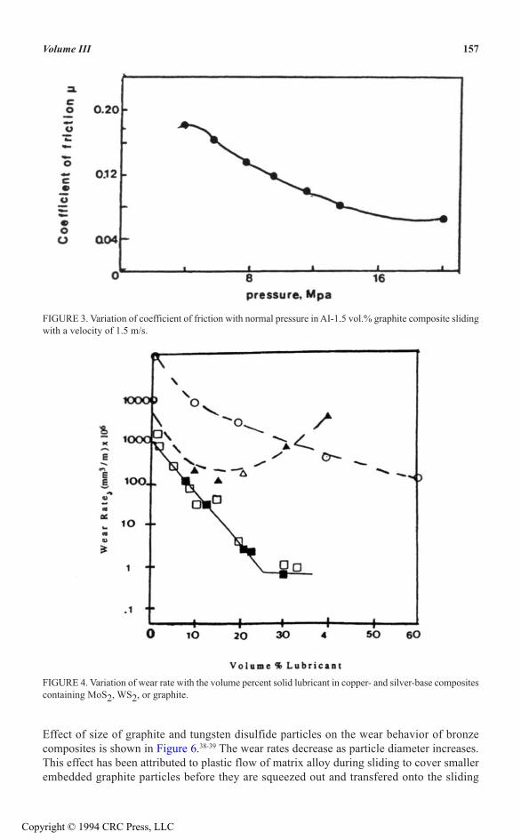
an Al-1.5 vol% graphite composite at a sliding velocity of 1.5 ms-1, as shown in Figure3.
Wear CharacteristicsFigure 4 shows that wear rate generally decreases with an increase in the amount of solid
lubricant in different metal matrix composites.23.29–30 In composites containing graphite, thewear rate is stabilized at a low value as the graphite content increases beyond some criticalpercentage which suggests that a lubrication film has covered the tribosurface completely Forcopper-WS2 composite, the wear rate initially reduces, but it increases when WS2 content ishigh. A similar phenomenon has been observed in Al-Pb composites by Mohan et al.31 Thisincrease in wear has been attributed to a drastic reduction in the strength of the composite anda faster build of the film and its wear. This critical lubricant level above which wear increasesmay vary from system to system.
Wear behavior in composites depends on the inherent nature of lubricating particles andtheir response to the smearing process. While wear rate generally increases as the loadincreases for aluminum silicon alloy-graphite composites, transition from mild to severe wearis not distinctly reflected in results under increasing load. However, the results on I copper-based lubricating particle composites show the transition in wear mechanism.35 Figure 5 showsthe variation of wear with sliding velocity in Al-Si alloy base composites containing I graphiteas compared with the matrix alloys.33–36As sliding speed increases, interface temperature alsoincreases, resulting in (1) an enhanced rate of formation of oxides on the sliding surface, and(2) a decrease in flow stress. In addition, there may be thermally activated microstructuralchanges like dissolution of precipitates, etc. In Figure 5 the composite with only 5% graphiteretains more or less the same trend of wear rate with sliding speed as that of the matrix.However, the composite with 15% graphite shows a different trend, which indicates that thesliding surface is largely covered by graphite film, and the wear rate becomes insensitive tochanges in sliding speed. Copper alloy base composites containing graphite and MoS2 showa similar trend for variation of wear rate with sliding speed.37
156 CRC Handbook of Lubrication and Tribology
FIGURE 2. Effect of matrix microstructure on the coefficient of friction in gray cast iron sliding against steel.
Copyright © 1994 CRC Press, LLC
Effect of size of graphite and tungsten disulfide particles on the wear behavior of bronzecomposites is shown in Figure 6.38-39 The wear rates decrease as particle diameter increases.This effect has been attributed to plastic flow of matrix alloy during sliding to cover smallerembedded graphite particles before they are squeezed out and transfered onto the sliding
157Volume III
FIGURE 3. Variation of coefficient of friction with normal pressure in AI-1.5 vol.% graphite composite slidingwith a velocity of 1.5 m/s.
FIGURE 4. Variation of wear rate with the volume percent solid lubricant in copper- and silver-base compositescontaining MoS2, WS2, or graphite.
Copyright © 1994 CRC Press, LLC

surface. The smaller the particle and the more ductile the matrix, the greater the extent towhich the particles are covered. Sugishita and Fujiyoshi25 have observed the same effect hnodular cast iron where larger nodule size results in lower wear. Also, the thin layer of matrixflowing over the graphite during sliding undergoes larger deformation and results in increasedmetal removal by fatigue.
Kawamoto and Okabayashi22 investigated the effect of matrix microstructure on wear inspheroidal gray cast iron in dry sliding, as shown in Figure 7. Fully pearlitic matrix shows the
158 CRC Handbook of Lubrication and Tribology
FIGURE 6. Variation of wear rate with particle size in bronze-based composites containing WS2 or graphicparticles.
FIGURE 5. Variation of wear rate with sliding speed in Al-Si alloy base composite containing graphite andthe base alloys sliding against steel.
Copyright © 1994 CRC Press, LLC

lowest wear when compared with fully ferritic or a bull’s eye structure with free ferrite andpearlite in ratio of 1:1. Okumoto et al.40 observed that wear also depends on graphite shape.Gray cast iron with flake graphites has inferior wear resistance as compared to spheroidalgray cast iron. This may be due to lower matrix strength in gray cast iron containing flakegraphite, and also the small transverse dimension of the flake makes it more easily coveredby the matrix due to plastic flow at the surface during sliding. Wear rate also becomesanisotropic and dependent on relative orientation of the flakes and sliding direction.
Seizure CharacteristicsSeizure resistance of a material can be defined as its ability to withstand cold welding
under pressure during sliding contact. Seizure of aluminum on aluminum, particularly severeunder boundary lubrication and troublesome even under full film lubrication, can be improvedsignificantly by addition of only 2 vol% graphite particles.41 Das and Prasad34 concluded that3 vol% of graphite in Al-Si alloys increases seizure pressure by about 2 MPa over that for thebase alloy under boundary lubrication. Rohatgi et al.42 summarized seizure behaviors in Al-graphite by using normalized velocity and pressure. Liu et al.43 reported that Al-50 vol%graphite particle composites under dry sliding show almost the same seizure behavior as thatof the base alloy when speed is below 3 m/s, but superior seizure resistance is observed in Al-50 vol% graphite alloy above 3 m/s. It is evident that seizure resistance of aluminum alloyscan be improved by adding graphite particles and that solid lubricants in composites aregenerally effective in interfering with asperity interactions and cold welding.
EFFECT OF ENVIRONMENTAL FACTORS ON FRICTION AND WEAR
Environmental Conditions and LubricationEnvironmental factors significantly affect the lubricity of solid lubricants such as graphite,
BN, and graphite fluoride. Graphite has a layered structure with weak interlayer bondingwhich allows smearing on the surface rubbed against it by interlayer slippage, but easyslippage of one layer over another occurs only in presence of water vapor or some volatileorganic solvents.44 Similar results have been reported in metal matrix composites containinggraphite. Effect of environmental gases on friction and wear of Ag-25% graphite composites
159Volume III
FIGURE 7. Effect of matrix microstructures on wear rate in gray cast iron sliding against steel under normalload of 50 N.
Copyright © 1994 CRC Press, LLC
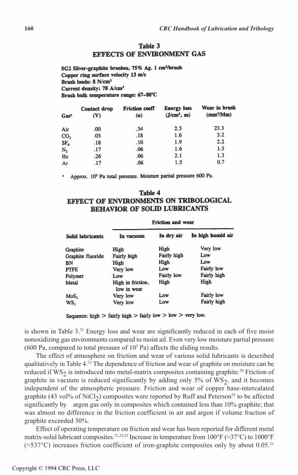
is shown in Table 3.51 Energy loss and wear are significantly reduced in each of five moistnonoxidizing gas environments compared to moist ail. Even very low moisture partial pressure(600 Pa, compared to total pressure of 105 Pa) affects the sliding results.
The effect of atmosphere on friction and wear of various solid lubricants is describedqualitatively in Table 4.23 The dependence of friction and wear of graphite on moisture can bereduced if WS2 is introduced into metal-matrix composites containing graphite.29 Friction ofgraphite in vacuum is reduced significantly by adding only 5% of WS2, and it becomesindependent of the atmospheric pressure. Friction and wear of copper base-intercalatedgraphite (43 vol% of NiCl2) composites were reported by Ruff and Peterson53 to be affectedsignificantly by argon gas only in composites which contained less than 10% graphite; thatwas almost no difference in the friction coefficient in air and argon if volume fraction ofgraphite exceeded 30%.
Effect of operating temperature on friction and wear has been reported for different metalmatrix-solid lubricant composites.21,23,52 Increase in temperature from 100°F (≈37°C) to 1000°F(≈537°C) increases friction coefficient of iron-graphite composites only by about 0.05.21
160 CRC Handbook of Lubrication and Tribology
Copyright © 1994 CRC Press, LLC

Friction coefficient increases by about 0.1 for Cu-20% WS2 composites.29 Lubricity of solidlubricants is generally retained up to the temperature ranges shown in Table 1. Easy flow ofmatrix material at elevated temperature may be primarily responsible for a higher coefficientof friction because more coverage of solid lubricant particles by matrix reduces the supply ofsolid lubricants onto the tribosurface for film formation. Matrix flow also explains the largeincrease in coefficient of friction in composites containing smaller particles and lower volumefractions of lubricant.
Galling resistance of aluminum alloys in the presence of oil lubrication can be improvedby dispersion of graphite particles54–55 in the matrix of aluminum alloys. Three causes maycontribute: (a) lubrication by graphite film between sliding surfaces, (b) improved lubricationdue to dispersion of debris of fine graphite particles in oil, and (c) voids left in the matrix aftertransfer of graphite acting as oil reservoir. Minimum graphite content required to inhibit gallingis about 2 wt% in Al-Si-Ni alloys.54–55
Effect of oil lubrication on wear behavior of composites containing graphite particles isillustrated in Figure 8, where wear volume is compared for Al-Si alloy base composites withdifferent graphite contents both during dry and during turbine oil lubrication.56 Only a smallamount of graphite (=4.2%) reduces wear volume drastically in the presence of oil, whileincrease in graphite content beyond this level results in enhanced wear. This may be due todispersion of higher amounts of graphite debris resulting in lower oil mobility.
Wear in Electrical ContactsSeveral composites designed for use in electrical contacts combine constituents to impart
excellent wear resistance with high electrical conductivity.30–37–45–51 The most widely usedinclude the less expensive copper-graphite composites and silver-graphite composites withvery low bulk and contact resistance.45 The amount of material removed in sliding electricalcontact is the sum of contributions from purely mechanical wear and an increment ofmechanical wear resulting from matrix softening by local heating due to arc.52 The wearmechanism for composites in electrical contacts is complex, and depends on composition of
161Volume III
FIGURE 8, Variation of wear volume with sliding distance in Al-Si alloy base composites containing graphitesliding against steel under lubrication of turbine oil.
Copyright © 1994 CRC Press, LLC
composites, the contact pairs, current and voltage level, sliding speed, environment, andcontact pressure.45,50,57,58
Tsuya and co-workers29 showed that the lubricating film affects the contact resistance insliding between a copper pin and the composites containing different amounts of WS2particles. Contact resistance did not increase significantly with an increase of WS2 particlesup to about 40% in a pure copper matrix, but contact resistance increased for WS2 contentabove 20% for copper-tin alloy base composites. The results suggest that contact resistancewill not increase sharply until the rubbing surfaces of the composites are covered completelyby lubricating film.
Lee and Johnson51 reported that in a silver-graphite system, wear rate of compositesincreased with an increase of current density at both low and high temperatures. Currentdensity is considerably higher for the same wear rate at higher temperatures as compared tothat at ambient temperature. Coefficient of friction decreased with increasing current density,both in air and in CO2 atmospheres.
The effect of sliding velocity on wear is complex. Teraoka37 has reported that inpantographs with contact strips made of copper-graphite composites, wear rate decreases assliding velocity increases from 6.9 to 27 m/s. The opposite results have been reported byCasstevens et al. for copper-lead alloy containing graphite at high sliding speeds of 750 m/sand by Johnson and Kuhlman-Wilsdorf20 for silver-graphite composite at speeds of 13 and 26m/s.
Arc erosion tests in copper-base composites show a steady increase in erosion with arecurrent.59 Erosion rates in copper-graphite and copper-matte composites are higher than thatof base metal. Marshall60 suggested that wear of these composite brushes resulted mainly frommechanical factors as compared to that from electrical current. Teraoka37 reported that thedifferent rail car-base affected the wear results of pantograph contact strips. Similar resultshave been reported by Lee and Johnson.51
FILM FORMATION
It has been observed that films of solid lubricant form on the sliding surfaces of variouscomposites containing solid lubricant particles. These films reduce the extent of direct metal-metal contact, as can be observed in typical SEM micrographs.43
When the surface of a composite containing solid lubricant particles is polished, plasticflow of the matrix occurring at the surface layer may cover particles, if small, to restrict theirtransfer to the tribosurface. Friction and wear of such surfaces are high until the layer over theparticles wears away partially, and the normal load can then squeeze lubricating material ontothe sliding surface.25 The lubricant particles are then sheared by asperities on the sliding surfaceand eventually spread into a film.
Rohatgi et al.”17,61 analyzed the sliding surface of Al-10 vol% graphite by Augerspectroscopy and established that the major elements on the tribosurface were oxygen, carbon,and aluminum. Over 30% of the surface was covered by graphite, a clear indication ofsmearing. However, thickness was not uniform; the film was generally 100 to 200 Å thick, butthere are places where the thickness was relatively large.” Film formation has also beenreported in other composites containing quite different solid lubricants like Pb.62
Ruff and Peterson53 observed similar film formation on copper-intercalated (NiCl2graphite composite test pins and on the steel counterface. The films were patchy in distribution;while surface profilometry indicated an average thickness of about 1.1 µm, some patches wereI as thick as 10 µm. They also observed that wear debris is preferentially collected at the Ientrance edge of the recessed graphite region and the graphite film is formed at the exit edge.Baranov and Pademo63 observed that the graphite smeared on the tribosurface in copper-graphite composites is preferentially oriented with basal planes (0001) parallel to tot slidingsurface.
162 CRC Handbook of Lubrication and Tribology
Copyright © 1994 CRC Press, LLC
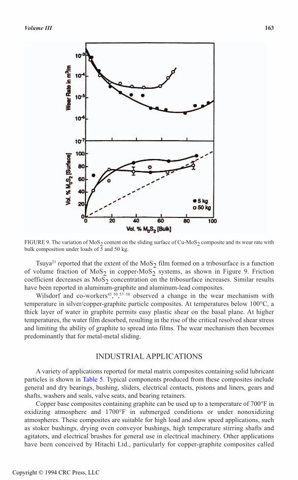
Tsuya23 reported that the extent of the MoS2 film formed on a tribosurface is a functionof volume fraction of MoS2 in copper-MoS2 systems, as shown in Figure 9. Frictioncoefficient decreases as MoS2 concentration on the tribosurface increases. Similar resultshave been reported in aluminum-graphite and aluminum-lead composites.
Wilsdorf and co-workers45,50,57–58 observed a change in the wear mechanism withtemperature in silver/copper-graphite particle composites. At temperatures below 100°C, athick layer of water in graphite permits easy plastic shear on the basal plane. At highertemperatures, the water film desorbed, resulting in the rise of the critical resolved shear stressand limiting the ability of graphite to spread into films. The wear mechanism then becomespredominantly that for metal-metal sliding.
INDUSTRIAL APPLICATIONS
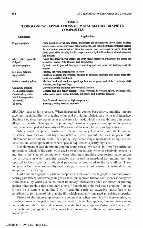
A variety of applications reported for metal matrix composites containing solid lubricantparticles is shown in Table 5. Typical components produced from these composites includegeneral and dry bearings, bushing, sliders, electrical contacts, pistons and liners, gears andshafts, washers and seals, valve seats, and bearing retainers.
Copper base composites containing graphite can be used up to a temperature of 700°F inoxidizing atmosphere and 1700°F in submerged conditions or under nonoxidizingatmospheres. These composites are suitable for high load and slow speed applications, suchas stoker bushings, drying oven conveyor bushings, high temperature stirring shafts andagitators, and electrical brushes for general use in electrical machinery. Other applicationshave been conceived by Hitachi Ltd., particularly for copper-graphite composites called
163Volume III
FIGURE 9. The variation of MoS2 content on the sliding surface of Cu-MoS2 composite and its wear rate withbulk composition under loads of 5 and 50 kg.
Copyright © 1994 CRC Press, LLC
GRADIA, cast under pressure. When dispersed in copper base alloys, graphite impartsexcellent machinability by breaking chips and providing lubrication at chip-tool interface.Graphite has, therefore, potential as a substitute for lead, which is a health hazard in copperalloys particularly when applied in plumbing.64 Stir-cast copper alloy-graphite compositeshave been developed at University of Wisconsin-Milwaukee for various applications.
Silver based composite brushes are marked by very low noise, and stable contactresistance, low friction, and high conductivity. Silver-graphite brushes suppress radiointerference noise and are useful for slipping, segmented rings, applications at high currentdensities, and other applications where special requirements justify high cost.
Development of cast aluminum-graphite composite alloys started in 1966 for antifrictionapplications. Much of the early work used powder metallurgy which is relatively expensiveand limits the size of components. Cast aluminum-graphite composites have uniquemicrostructure in which graphite particles are located in interdendrite regions; they arereported to have superior tribological properties as compared to the base alloys. Thesecomposites have been produced by sand casting, permanent mold casting, centrifugal casting,and pressure die casting.
Cast aluminum-graphite particle composites with over 2 vol% graphite have improvedbearing parameters, improved galling resistance, and reduced friction coefficients as comparedto the base alloy when evaluated under boundary lubrication either self mated or runningagainst other graphite-free aluminum alloys.54 Examination showed that a graphite film hadformed on a sample containing 2 vol% graphite particles; extensive subsurface shearcontributed to formation of this graphite film which apparently imparted antiseizing properties.
Pistons of aluminum-graphite particle composites, when tested in a HP diesel engine, ledto reduced wear of the piston and rings, reduced frictional horsepower, freedom from seizingunder adverse lubrication, and decreased specific fuel consumption. Pistons and liners of Al-Si eutectic alloy-graphite particle composite led to similar results in half horsepower petro-engines.65,66
164 CRC Handbook of Lubrication and Tribology
Copyright © 1994 CRC Press, LLC

Associated Engineering Company in Italy dispersed 4 vol% graphite particles inaluminum-18% silicon alloy. Tests of this composite mated with Al-11.48% silicon alloy inheated oil showed that scuffing resistance improved by a factor of two in comparison with thebase alloy.67.68 They further evaluated liners of these alloys in two-stroke and four-strokeengines in collaboration with Ferrari, Hiro, and Alpha Romeo for passenger and racing carapplications. The power generated was improved by 10%, there was no significant linear wear,and the pistons showed no signs of scuffing. Aluminum-graphite liners were fitted in AlphaRomeo racing cars which were victorious in the Formula 1975 World Championship. Noseizure was experienced in 1975, 1976, and 1977 racing sessions, and power ratings werefound to be high.68
REFERENCES1. Lancaster, J. K., Solid lubricants, in CRC Handbook of Lubrication, Vol. n, Booser, E. R., Ed., CRC Press.
Boca Raton, FL, p. 269.2. Rack, H. J., in Proc. Conf. Powder Metallurgy Composites, MSI, 1987, 155.3. Clauss, F. J., Solid Lubricants and Self-Lubricating Solids, Academic Press, New York, 1972.4. Ray, S., Indian J. Tech., 28, 368, 1990.5. Rohatgi, P. K., Asthana, R., and Das, S., Int. Met. Rev., 31, 115, 1986.6. Lavernia, E. J., Int. J. Rapid Solidification. 5, 47, 1989.7. Bowden, T. P. and Tabor, D., Friction and Lubrication of Solids I, Oxford Clarendon Press, Great Britain, 1950,
p. 19.8. Bridgeman, P. W., Proc. Am. Acad. Arts Sci., 387, 1936.9. Suh, N. P., Tribophysics. Prentice-Hall, NJ, 1986.
10. Abrahamson, E. P., Jahanmir, S., and Suh, N. P., CIRP Ann. Inst. Inst. Prod. Eng. Res., 24, 513, 1975.11. Raboniwicz, E., Friction and Wear of Materials, 1966, John Wiley & Sons, New York, 1966.12. Gibson, P. R., Clegg, A. J., and Das, A. A., Wear, 95, 193, 1984.13. Lancaster, J. K., in New Directions in Lubrication, Materials, Wear and Surface Interaction-Tribology in the
80’s, Loomis, W. R., Ed., Noyes Publications, Park Ridge, NJ, 1983, 320.14. Pardee, R. P., IEEE Trans., PAS-86, 616, 1967.15. Dillich, S. and Kuhlmann-Wilsdorf, D., Mater. Sci. Eng., 57. 213, 1983.16. Rybakova, L. M. and Kuksenova, L. I., Soviet Eng. Res., 5, 9, 1985.17. Rohatgi, P. K., Liu, Y., and Bar, T. L., Mater. Sci. Eng., A123, 213, 1990.18. Rohatgi, P. K., Liu, Y., and Barr, T. L., Metall. Trans. 1991.19. Yuasa, E., Morooka, T., and Hayama, F., J. Jpn. Inst. Met., 50, 1032, 1986.20. Johnson, L. B., Jr. and Kuhlmann-Wilsdorf, D., Mater. Sci. Eng. 58, 4, 1983.21. Bowen, P. H., Much. Des., 7, 195, 1963.22. Kawamoto, M. and Okabayashi, K., Wear. 58, 59, 1980.23. Tsuya, J. Jpn. Inst. Composites, 11, 127, 1985.24. Owen, K. C., Wang, M. J., Prasad, C., and Eliezer, Z., Wear, 120, 117, 198725. Sugishita, J. and Fujiyoshi, S., Wear, 68, 7, 1981.26. Kawamoto, M., Adach, M., Ando, A., and Okabayashi, K., J. Jpn. Foundrymen’s Soc. 50,32, 1978.27. Barry, H. F. and Binkelman, J. P., Lubr. Eng., 22, 139, 1962.28. Muran, M. and Srnanek, M., Kovove Mater., 23, 107, 1985.29. Tsuya, Y., Shimura, H., and Umeda, K., Wear, 22, 143, 1972.30. Johnson, J. L. and Morberly, L. E., IEEE Trans: Compon. Hybr. Manuf. Tech., 1978 (CHMT-1), p. 36.31. Mohan, S., Agarwala, V., and Ray, S., Z. Metallkunde. 80, 904, 1989.32. Suwa, M., Komuro, K., and Soeno, K., J. Jpn. Inst. Met., 40, 1074, 1976.33. Choo, W. K. and Hong, C. H., J. Korean Inst. Met.. 17, 474, 1979.34. Das, S. and Prasad, V., Wear. 133, 136, 1989.35. Suwa, M., Hitachi Graphite-Dispersed East Alloy-Gradia. Hitachi Report, 1986.36. Yuasa, E., Morooka, T., and Hayama, F. J., J. Jpn. Inst. Met., 50, 1032, 1986.37. Teraoka, T., Wear of arc resistant sintered copper alloy for pantograph. Technical Report, Railway Technical
Research Institute, Japan, 1983, 5.38. Al’tman, V.A., Malakhov, G. V., Memelov, V. L., and Osipova, E. G., Sov. J. Friction and Wear, 10, 873, 1989.39. Suwa, M., Komuro, K., and Yamada, T., J. Jpn. Inst. Mel., 42, 1034, 1978.
165Volume III
Copyright © 1994 CRC Press, LLC

40. Okumoto, T., Sasaki, T., and Yamada, T., J. Jpn. Foundrymen’s Soc, 46, 913, 1974.41. Pai, B. C., and Rohatgi, P. K., Trans. Indian Inst. Met., 27, 97, 1974.42. Rohatgi, P. K., Lin, Y., andAsthana, R., in Proc. Conf. Tribol. Composite Mater., Rohatgi, P.K., Blau, P. J., and
Yust, C. S., Eds., ASM Int., 1990, 69.43. Liu, Y., Rohatgi, P. K., Ray, S., and Barr, T. L., in Proc. Int. Conf. Composite Mater., (ICCM/8), Tsai, S. W.
and Springer, O. S., Eds., Honolulu, 1991, 204.44. Savage, R. H. and Schaefer, D. L., J. Appl. Phys., 27, 136, 1956.45. Kuhimann-Wilsdorf, D., Makel, D. D., Sondergaard, N. A., and Maribo, D. W., in Proc. Cost Reinforced
Metal Composites, Fishman, S. G. and Dhingra, A. K., Eds., ASM Int., 1988, 347.46. Johnson, J. L. and Scheurs, J., Wear, 78, 219, 198247. Casstevens, J. M., Rylander, H. G., and Eliezer, Z., Wear, 48, 121, 1978.48. Casstevens, J. M., Rylander, H. G., and Eliezer, Z., Wear, 48, 409, 1978.49. Baker, R. M. and Hewitt, G. W., J. Bear. (London). 33, 287, 1936.50. Johnson, L. B. and Kuhlmann-Wilsdorf, Mater. Sci. Eng., 58, 21, 1983.51. Lee, P. K. and Johnson, J. L., IEEE Trans., Vol. CHMT-1, 1978, 40.52. Tsuya, Y., Umeda, K., and Saito, K., in Proc. 2nd Int. Conf. Solid Lubr.. Denver, 1978, 212.53. Ruff, A. W. and Peterson, M. B., in Proc. Tribology of Composite Mater.. Rohatgi, P. K., Blau, P. J.. and Yust,
C. S., Eds., ASM Int., Oak Ridge, TN, 1990, 43.54. Badia, F. A. and Rohatgi, P. K., Trans. Am. Foundrymen’s Soc, 77, 402, 1969.55. Badia, F. A., SAE Pap.. No. GT89–073, 1989, 1.56. Suwa, M., Komuro, K., and Soeno, K” J. Jpn. Inst. Met., 40, 1074, 1976.57. Kuhrmarm-Wilsdori, D., ASME, J. Tribal, 109, 321,1987.58. Kuhlmann-Wilsdorf, D., Makel, D. D., Sondergaard, N. A., and Marino, D. M., in 14th Int. Conf. Electr.
Contacts, Paris, IEEE, 1988, 1.59. Jones, L., The Physics of Electrical Contacts, Clarendon Press, Oxford, 1957.60. Marshall, R. A., Report No. EP-RR-3, Canberra, Australia, 1964.61. Rohatgi, P. K., Liu, Y., and Barr, T. L., in Proc. Tribology of Composite Mater., Rohatgi, P. K., Blau, P. J., and
Yust, C. S., Eds., ASM Int., 1990, 113.62. Mohan, S., Agarwala, V., and Ray, S., Wear, 140, 83, 1990.63. Baranov, N. G. and Paderno, V. N., Sov. J. Friction and Wear, 10, 662, 1989.64. Rohatgi, P. K., Ray, S., and Liu, Y., Int. Metall. Revs., 37, 3, 129, 1992.65. Krishnan, B. P., Raman, N., Narayauaswamy, K., and Rohatgi, P. K., Tribol. Int., 16,239,1983.66. Krishnan, B. P., Raman, N., Narayauaswamy, K., and Rohatgi, P. K., Wear. 60, 205, 1981.67. Bruni, L. and Iguera, P., Automob. Eng., 3, 29, 1978.68. Bruni, L., AE Symposium, Part m, Italy 1987, 207.
166 CRC Handbook of Lubrication and Tribology
Copyright © 1994 CRC Press, LLC