mercedes benz table of contents · mercedes benz code scanner cs1000 ob15-11 10 connection table...
TRANSCRIPT
Mercedes Benz Code Scanner CS1000 OB15-11
2
Table of Contents
ANALOG FAULT CODES
ELECTRONIC DIESEL IDLE SPEED CONTROL (ELR)201.126 1989 . . . . . . . . . . . . . . . . . . . . . . . . . . 19
ELECTRONIC DIESEL SYSTEM (EDS)124.128 1990-91 . . . . . . . . . . . . . . . . . . . . . . . . 20126.134 126.135 1990-91 . . . . . . . . . . . . . . . . . . . . . . . . 20124.128 1992-93 . . . . . . . . . . . . . . . . . . . . . . . . 21140.134 1992-93 . . . . . . . . . . . . . . . . . . . . . . . . 21
CONTINUOUS FUEL INJECTION SYSTEM (CFI)124.026 124.030 124.050 124.090 1988-89 (California version only) . . . . . 22126.024 126.025 1988-89 (California version only) . . . . . 22201.028 (1988-93) 201.029 1988-89 (California version only) . . . . . 22107.048 1988-91 (California version only) . . . . . 22126.035 126.039 126.045 1988-91 (California version only) . . . . . 22124.026 124.030 124.090 124.230 124.290 1990-93 . . . . . . . . . . . . . . . . . . . . . . . . 23126.024 126.025 1990-93 . . . . . . . . . . . . . . . . . . . . . . . . 23201.029 1990-93 . . . . . . . . . . . . . . . . . . . . . . . . 23124.051 129.061 1990-93 . . . . . . . . . . . . . . . . . . . . . . . . 25129.066 1990-92 . . . . . . . . . . . . . . . . . . . . . . . . 25
CONTINUOUS FUEL INJECTION SYSTEM (MAS CONTROLLER)124.026 124.030 124.090 124.230 124.290 1990-92 . . . . . . . . . . . . . . . . . . . . . . . . 27129.066 1990-92 . . . . . . . . . . . . . . . . . . . . . . . . 27201.029 1990-92 . . . . . . . . . . . . . . . . . . . . . . . . 27
1. Turn on the ignition (engine not started)
2. Press and hold the red button for about 2-3 seconds and release. Count the number of lights and write them down. This is your DTC number. Continue until the light count repeats itself. No light flashes or 1 flash indicate no code is stored.
3. On your computer, open the PDF code file and open the search box using “Ctrl-f”. In the search box, enter the “socket ##”. Press “Enter” and find the socket ## , car year and model. Look for the light flash number in the DTC Readout column.
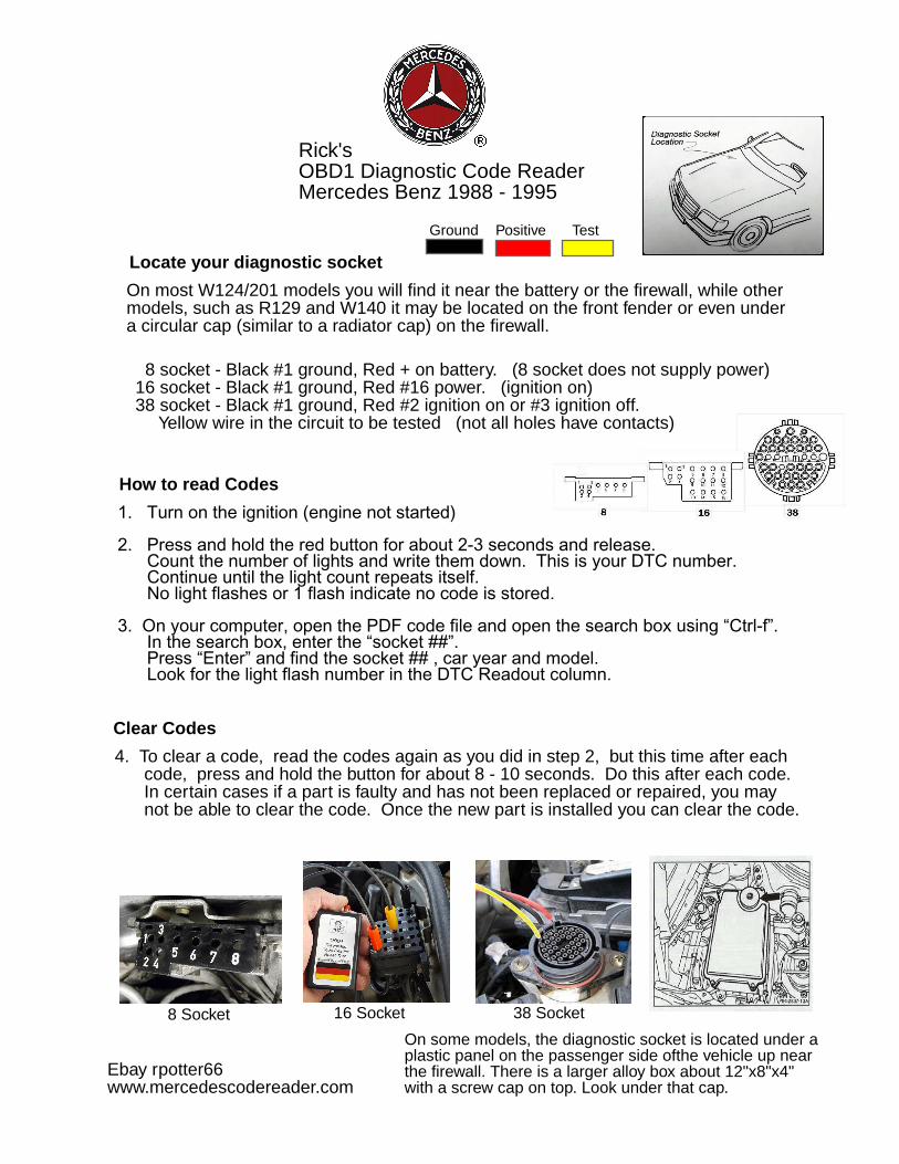
On most W124/201 models you will find it near the battery or the firewall, while othermodels, such as R129 and W140 it may be located on the front fender or even undera circular cap (similar to a radiator cap) on the firewall.
How to read Codes
Mercedes Benz 1988 - 1995
16 Socket
On some models, the diagnostic socket is located under aplastic panel on the passenger side ofthe vehicle up nearthe firewall. There is a larger alloy box about 12"x8"x4"with a screw cap on top. Look under that cap.
8 Socket
Ebay rpotter66
8 socket - Black #1 ground, Red + on battery. (8 socket does not supply power)16 socket - Black #1 ground, Red #16 power. (ignition on)38 socket - Black #1 ground, Red #2 ignition on or #3 ignition off. Yellow wire in the circuit to be tested (not all holes have contacts)
Clear Codes
4. To clear a code, read the codes again as you did in step 2, but this time after each code, press and hold the button for about 8 - 10 seconds. Do this after each code. In certain cases if a part is faulty and has not been replaced or repaired, you may not be able to clear the code. Once the new part is installed you can clear the code.
38 Socket
Ground Positive Test
Locate your diagnostic socket
OBD1 Diagnostic Code Reader Manual
www.mercedescodereader.com
Rick'sOBD1 Diagnostic Code ReaderMercedes Benz 1988 - 1995
Ebay rpotter66www.mercedescodereader.com
Mercedes OBD1 diagnostic codes - 1988-1995Rick's Mercedes Code Reader - ebay rpotter66 or www.mercedescodereader.com
Table of Contents
8 - Socket Diagnostic Connector ....................... 316 - Socket Diagnostic Connector ....................... 438 - Socket Diagnostic Connector ....................... 5,6 9 - Socket Diagnostic Connector ....................... 6
Obd1 Analog Codes ....................... 7
Active, Stored and Registered Fault Codes ....................... 109Mercedes System With Abbreviations ....................... 110Mercedes Acronyms ....................... 111Mercedes USA Model Identifier ....................... 115
Mercedes Benz Code Scanner CS1000 OB15-11
10
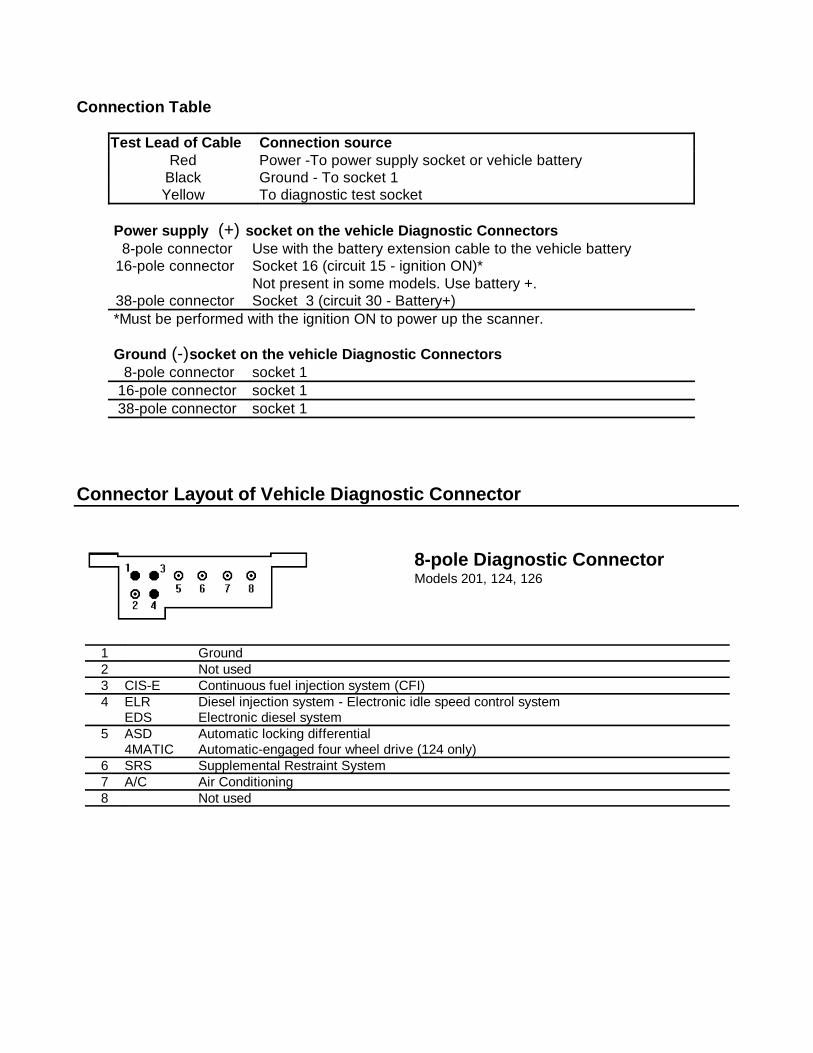
Connection Table
Test Lead of Cable Connection source Red Power -To power supply socket or vehicle battery
Black Ground - To socket 1Yellow To diagnostic test socket
Power supply (B+) so cket on the vehicle Dia gnostic Connectors 8-pole connector Use with the battery extension cable to the vehicle battery16-pole connector Socket 16 (circuit 15 - ignition ON)*
Not present in some models. Use battery +.38-pole connector Socket 3 (circuit 30 - Battery+)*Must be performed with the ignition ON to power up the scanner.
Ground (-) so cket on the vehicle Dia gnostic Connectors 8-pole connector socket 116-pole connector socket 138-pole connector socket 1
Connector Layout of Vehicle Diagnostic Connector
8-pole Diagnostic ConnectorModels 201, 124, 126
1 Ground2 Not used3 CIS-E Continuous fuel injection system (CFI)4 ELR
EDSDiesel injection system - Electronic idle speed control systemElectronic diesel system
5 ASD4MATIC
Automatic locking differentialAutomatic-engaged four wheel drive (124 only)
6 SRS Supplemental Restraint System7 A/C Air Conditioning8 Not used
(+)
(-)
Mercedes Benz Code Scanner CS1000 OB15-11
11
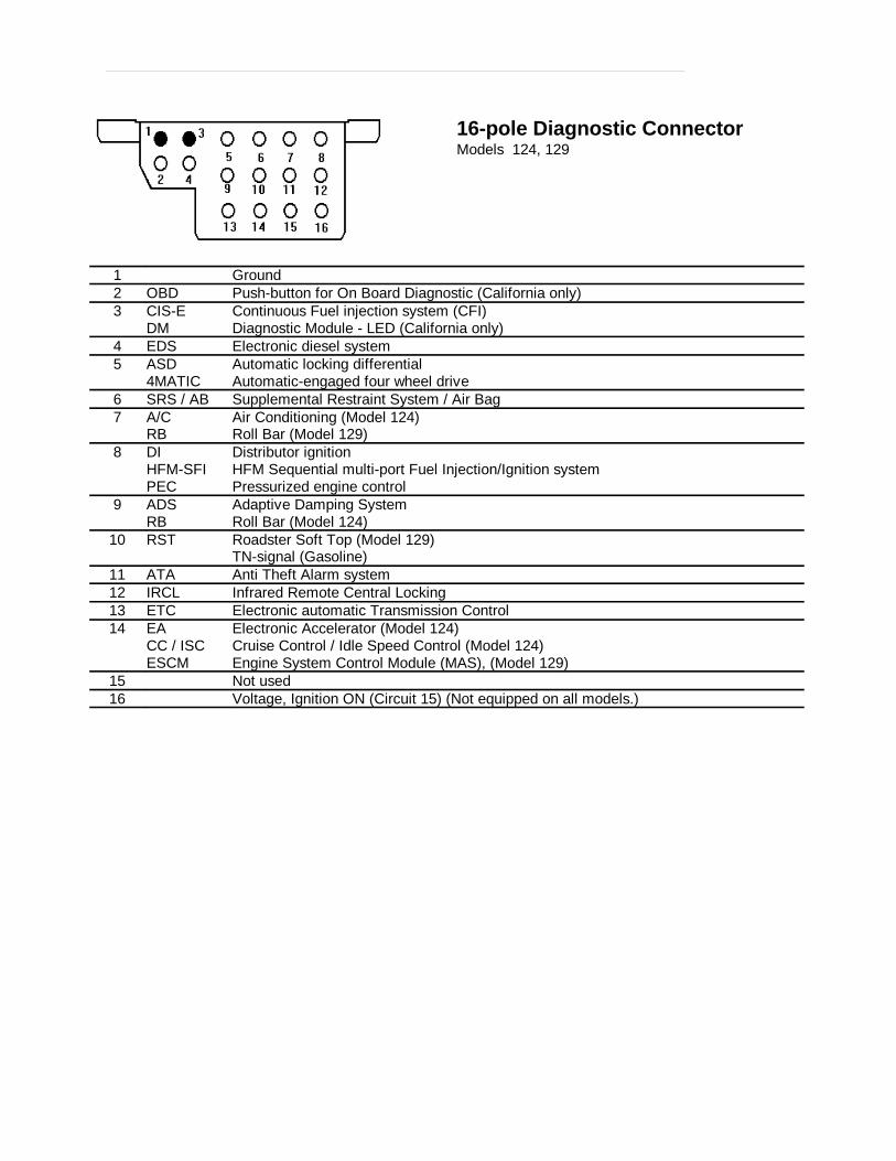
16-pole Diagnostic ConnectorModels 124, 129
1 Ground2 OBD Push-button for On Board Diagnostic (California only)3 CIS-E
DMContinuous Fuel injection system (CFI)Diagnostic Module - LED (California only)
4 EDS Electronic diesel system5 ASD
4MATICAutomatic locking differentialAutomatic-engaged four wheel drive
6 SRS / AB Supplemental Restraint System / Air Bag7 A/C
RBAir Conditioning (Model 124)Roll Bar (Model 129)
8 DIHFM-SFIPEC
Distributor ignition HFM Sequential multi-port Fuel Injection/Ignition systemPressurized engine control
9 ADSRB
Adaptive Damping SystemRoll Bar (Model 124)
10 RST Roadster Soft Top (Model 129)TN-signal (Gasoline)
11 ATA Anti Theft Alarm system12 IRCL Infrared Remote Central Locking13 ETC Electronic automatic Transmission Control14 EA
CC / ISCESCM
Electronic Accelerator (Model 124)Cruise Control / Idle Speed Control (Model 124)Engine System Control Module (MAS), (Model 129)
15 Not used16 Voltage, Ignition ON (Circuit 15) (Not equipped on all models.)
Mercedes Benz Code Scanner CS1000 OB15-11
12
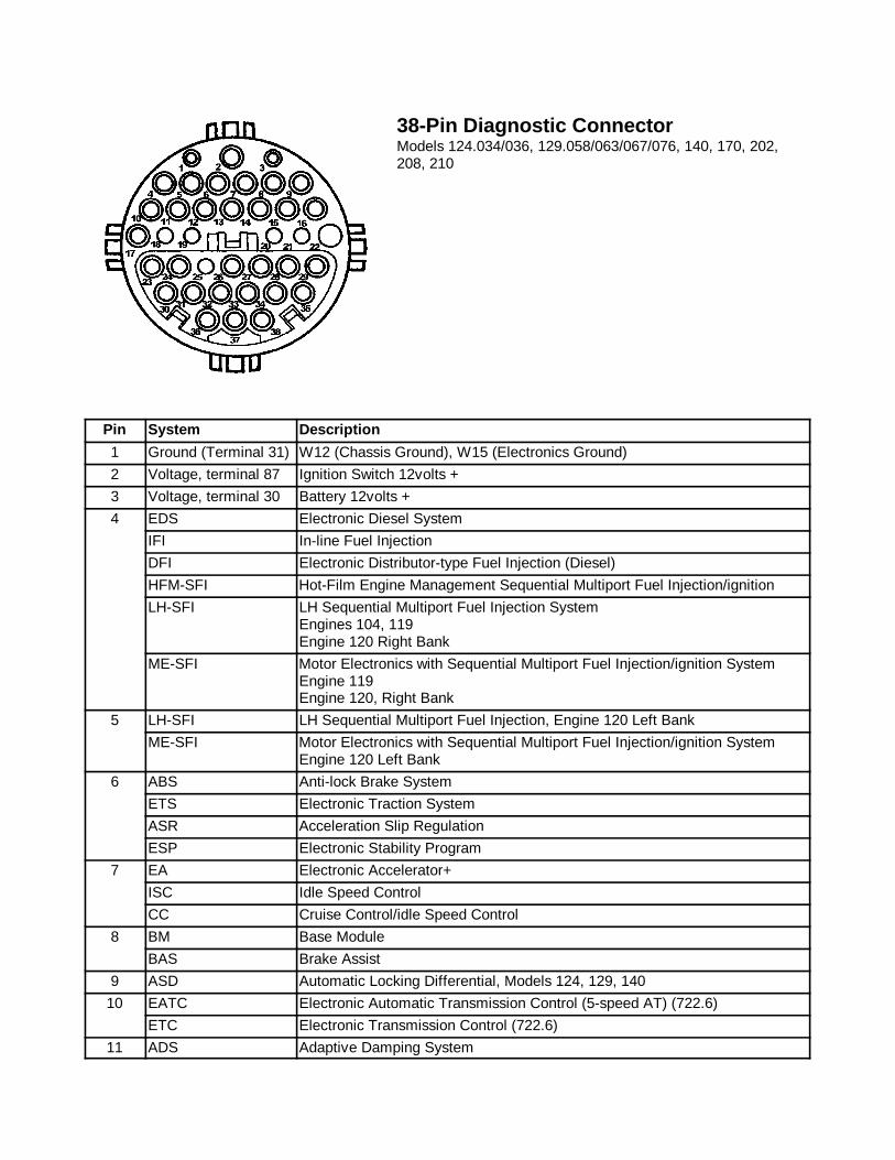
38-Pin Diagnostic Connector Models 124.034/036, 129.058/063/067/076, 140, 170, 202,208, 210
The Mercedes Diagnostic “Mushroom” #140-1463 availablefrom Baum Tools Unltd. is recommended to allow easyaccess to the diagnostic connector. Call 800-848-6657 or 941-927-1414 for more information.
Pin System Description
1 Ground (Terminal 31) W12 (Chassis Ground), W15 (Electronics Ground)
2 Voltage, terminal 87 Ignition Switch 12volts +
3 Voltage, terminal 30 Battery 12volts +
4 EDS Electronic Diesel System
IFI In-line Fuel Injection
DFI Electronic Distributor-type Fuel Injection (Diesel)
HFM-SFI Hot-Film Engine Management Sequential Multiport Fuel Injection/ignition
LH-SFI LH Sequential Multiport Fuel Injection SystemEngines 104, 119Engine 120 Right Bank
ME-SFI Motor Electronics with Sequential Multiport Fuel Injection/ignition System Engine 119Engine 120, Right Bank
5 LH-SFI LH Sequential Multiport Fuel Injection, Engine 120 Left Bank
ME-SFI Motor Electronics with Sequential Multiport Fuel Injection/ignition SystemEngine 120 Left Bank
6 ABS Anti-lock Brake System
ETS Electronic Traction System
ASR Acceleration Slip Regulation
ESP Electronic Stability Program
7 EA Electronic Accelerator+
ISC Idle Speed Control
CC Cruise Control/idle Speed Control
8 BM Base Module
BAS Brake Assist
9 ASD Automatic Locking Differential, Models 124, 129, 140
10 EATC Electronic Automatic Transmission Control (5-speed AT) (722.6)
ETC Electronic Transmission Control (722.6)
11 ADS Adaptive Damping System
Mercedes Benz Code Scanner CS1000 OB15-11
13
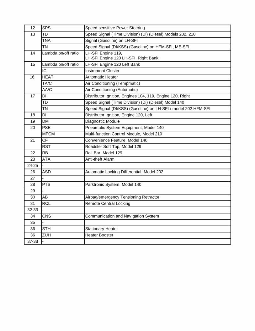
12 SPS Speed-sensitive Power Steering
13 TD Speed Signal (Time Division) (Di) (Diesel) Models 202, 210
TNA Signal (Gasoline) on LH-SFI
TN Speed Signal (DI/KSS) (Gasoline) on HFM-SFI, ME-SFI
14 Lambda on/off ratio LH-SFI Engine 119, LH-SFI Engine 120 LH-SFI, Right Bank
15 Lambda on/off ratio LH-SFI Engine 120 Left Bank
IC Instrument Cluster
16 HEAT Automatic Heater
TA/C Air Conditioning (Tempmatic)
AA/C Air Conditioning (Automatic)
17 DI Distributor Ignition, Engines 104, 119, Engine 120, Right
TD Speed Signal (Time Division) (Di) (Diesel) Model 140
TN Speed Signal (DI/KSS) (Gasoline) on LH-SFI / model 202 HFM-SFI
18 DI Distributor Ignition, Engine 120, Left
19 DM Diagnostic Module
20 PSE Pneumatic System Equipment, Model 140
MFCM Multi-function Control Module, Model 210
21 CF Convenience Feature, Model 140
RST Roadster Soft Top, Model 129
22 RB Roll Bar, Model 129
23 ATA Anti-theft Alarm
24-25 -
26 ASD Automatic Locking Differential, Model 202
27 -
28 PTS Parktronic System, Model 140
29 -
30 AB Airbag/emergency Tensioning Retractor
31 RCL Remote Central Locking
32-33 -
34 CNS Communication and Navigation System
35 -
36 STH Stationary Heater
36 ZUH Heater Booster
37-38 -
9-Pole Diagnostic Connector (1980-94)The 9-pole Diagnostic Connector is used on earlier model vehicles. It can displayon-off ratio fault codes (1986 and later), RPM and Lambda sensor values. Variouson-off ratio Meters are available that provide access to this type of diagnosticconnector. Call Baum Tools at 800-848-6657 or 941-927-1414 for more informationon these meters.
The 9-pole diagnostic Connecor is used on earlier model vehicles.It can display on-off fault codes (1986 and later), RPM andLambda values. An Ohm meter can be used.
9-Pole Diagnostic Connector (1980-94)
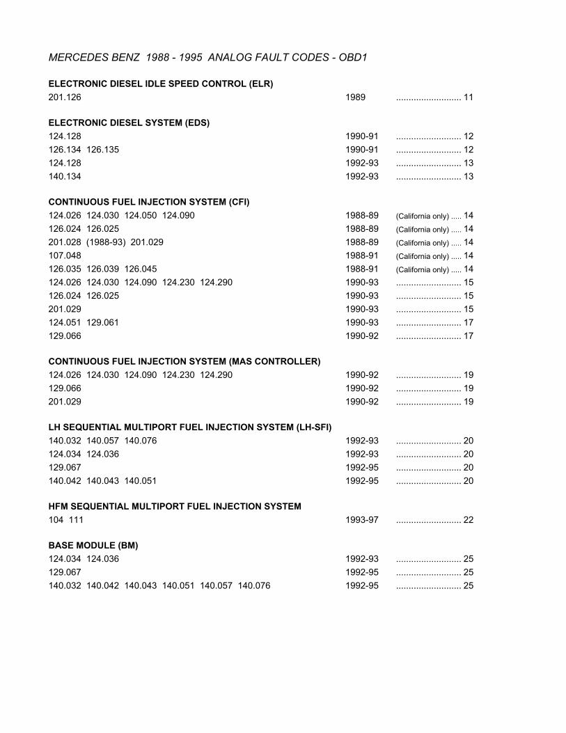
MERCEDES BENZ 1988 - 1995 ANALOG FAULT CODES - OBD1
ELECTRONIC DIESEL IDLE SPEED CONTROL (ELR)201.126 1989 .......................................11
ELECTRONIC DIESEL SYSTEM (EDS)124.128 1990-91 .......................................12126.134 126.135 1990-91 .......................................12124.128 1992-93 .......................................13140.134 1992-93 .......................................13
CONTINUOUS FUEL INJECTION SYSTEM (CFI)124.026 124.030 124.050 124.090 1988-89 (California only) ...........14126.024 126.025 1988-89 (California only) ...........14201.028 (1988-93) 201.029 1988-89 (California only) ...........14107.048 1988-91 (California only) ...........14126.035 126.039 126.045 1988-91 (California only) ...........14124.026 124.030 124.090 124.230 124.290 1990-93 .......................................15126.024 126.025 1990-93 .......................................15201.029 1990-93 .......................................15124.051 129.061 1990-93 .......................................17129.066 1990-92 .......................................17
CONTINUOUS FUEL INJECTION SYSTEM (MAS CONTROLLER)124.026 124.030 124.090 124.230 124.290 1990-92 .......................................19129.066 1990-92 .......................................19201.029 1990-92 .......................................19
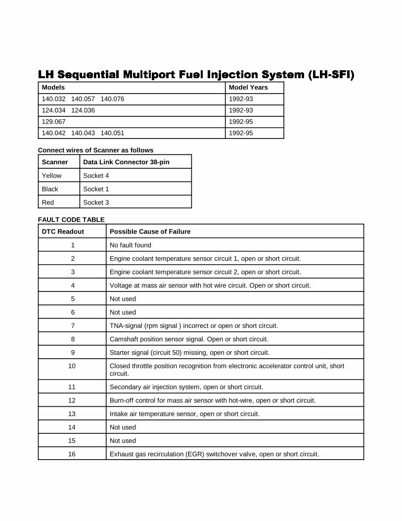
LH SEQUENTIAL MULTIPORT FUEL INJECTION SYSTEM (LH-SFI)140.032 140.057 140.076 1992-93 .......................................20124.034 124.036 1992-93 .......................................20129.067 1992-95 .......................................20140.042 140.043 140.051 1992-95 .......................................20
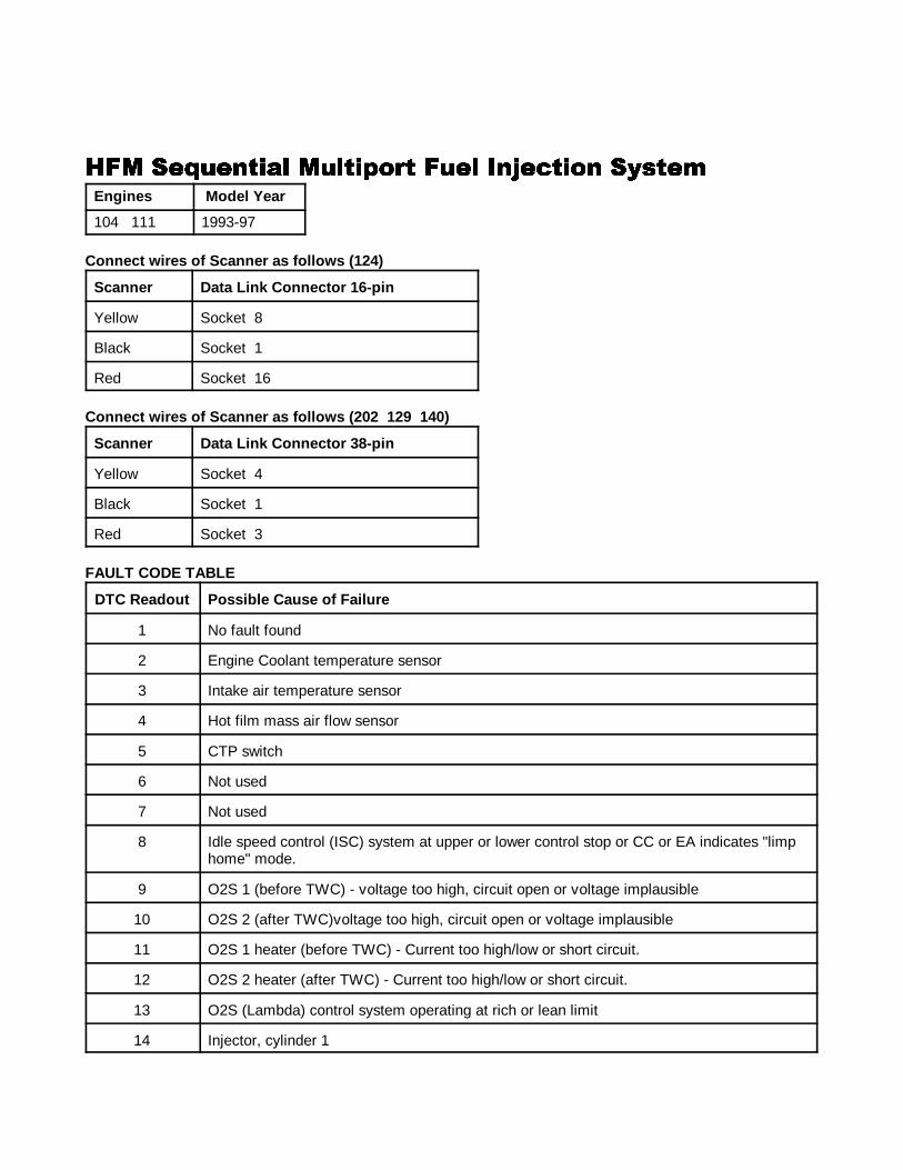
HFM SEQUENTIAL MULTIPORT FUEL INJECTION SYSTEM104 111 1993-97 .......................................22
BASE MODULE (BM)124.034 124.036 1992-93 .......................................25129.067 1992-95 .......................................25140.032 140.042 140.043 140.051 140.057 140.076 1992-95 .......................................25
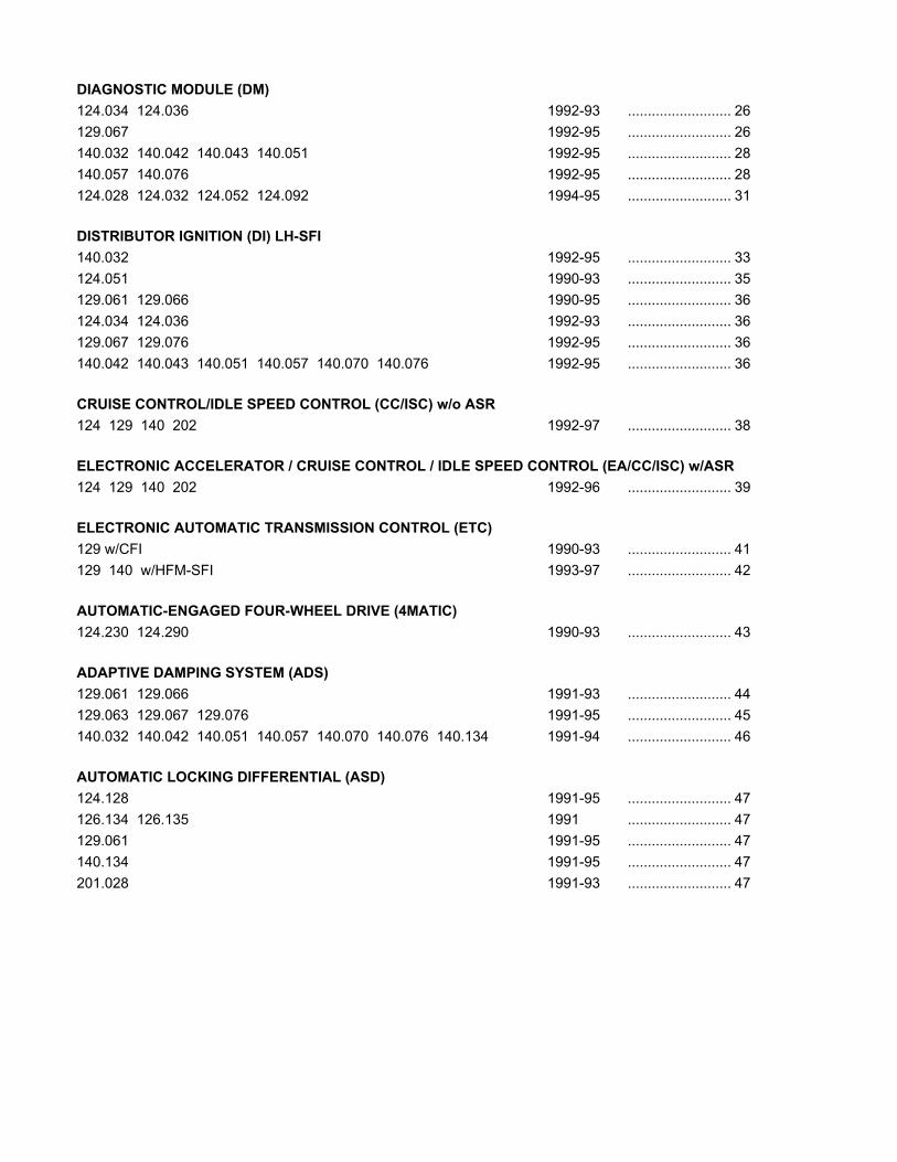
DIAGNOSTIC MODULE (DM)124.034 124.036 1992-93 .......................................26129.067 1992-95 .......................................26140.032 140.042 140.043 140.051 1992-95 .......................................28140.057 140.076 1992-95 .......................................28124.028 124.032 124.052 124.092 1994-95 .......................................31
DISTRIBUTOR IGNITION (DI) LH-SFI140.032 1992-95 .......................................33124.051 1990-93 .......................................35129.061 129.066 1990-95 .......................................36124.034 124.036 1992-93 .......................................36129.067 129.076 1992-95 .......................................36140.042 140.043 140.051 140.057 140.070 140.076 1992-95 .......................................36
CRUISE CONTROL/IDLE SPEED CONTROL (CC/ISC) w/o ASR124 129 140 202 1992-97 .......................................38
ELECTRONIC ACCELERATOR / CRUISE CONTROL / IDLE SPEED CONTROL (EA/CC/ISC) w/ASR124 129 140 202 1992-96 .......................................39
ELECTRONIC AUTOMATIC TRANSMISSION CONTROL (ETC)129 w/CFI 1990-93 .......................................41129 140 w/HFM-SFI 1993-97 .......................................42
AUTOMATIC-ENGAGED FOUR-WHEEL DRIVE (4MATIC)124.230 124.290 1990-93 .......................................43
ADAPTIVE DAMPING SYSTEM (ADS)129.061 129.066 1991-93 .......................................44129.063 129.067 129.076 1991-95 .......................................45140.032 140.042 140.051 140.057 140.070 140.076 140.134 1991-94 .......................................46
AUTOMATIC LOCKING DIFFERENTIAL (ASD)124.128 1991-95 .......................................47126.134 126.135 1991 .......................................47129.061 1991-95 .......................................47140.134 1991-95 .......................................47201.028 1991-93 .......................................47
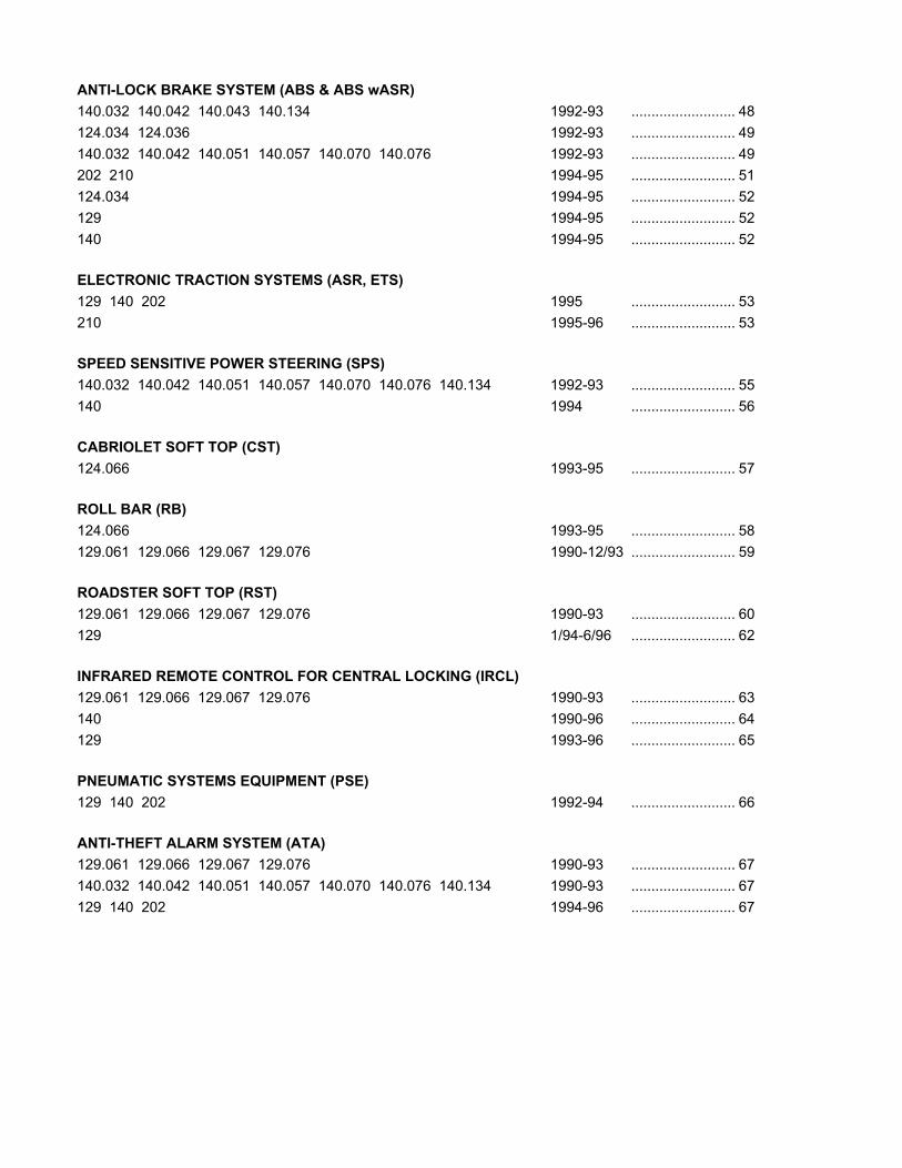
ANTI-LOCK BRAKE SYSTEM (ABS & ABS wASR)140.032 140.042 140.043 140.134 1992-93 .......................................48124.034 124.036 1992-93 .......................................49140.032 140.042 140.051 140.057 140.070 140.076 1992-93 .......................................49202 210 1994-95 .......................................51124.034 1994-95 .......................................52129 1994-95 .......................................52140 1994-95 .......................................52
ELECTRONIC TRACTION SYSTEMS (ASR, ETS)129 140 202 1995 .......................................53210 1995-96 .......................................53
SPEED SENSITIVE POWER STEERING (SPS)140.032 140.042 140.051 140.057 140.070 140.076 140.134 1992-93 .......................................55140 1994 .......................................56
CABRIOLET SOFT TOP (CST)124.066 1993-95 .......................................57
ROLL BAR (RB)124.066 1993-95 .......................................58129.061 129.066 129.067 129.076 1990-12/93 ...................................59
ROADSTER SOFT TOP (RST)129.061 129.066 129.067 129.076 1990-93 .......................................60129 1/94-6/96 ...................................62
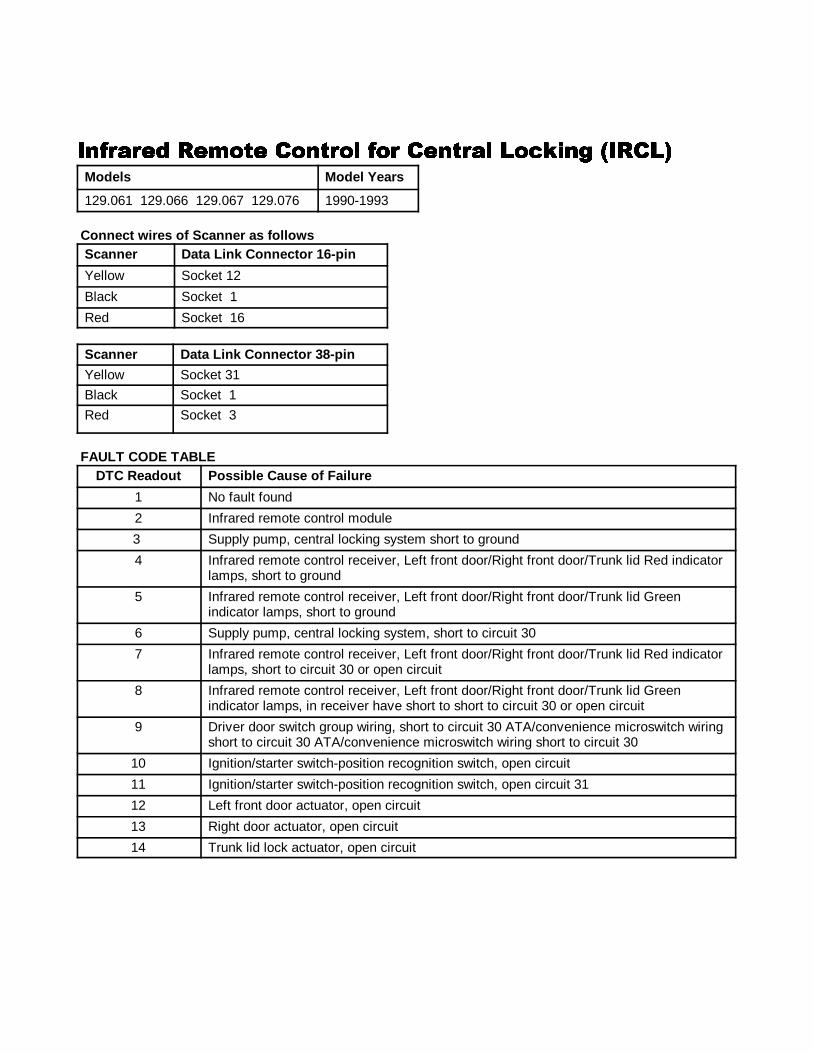
INFRARED REMOTE CONTROL FOR CENTRAL LOCKING (IRCL)129.061 129.066 129.067 129.076 1990-93 .......................................63140 1990-96 ...................................64129 1993-96 .......................................65
PNEUMATIC SYSTEMS EQUIPMENT (PSE)129 140 202 1992-94 .......................................66
ANTI-THEFT ALARM SYSTEM (ATA)129.061 129.066 129.067 129.076 1990-93 .......................................67140.032 140.042 140.051 140.057 140.070 140.076 140.134 1990-93 ...................................67129 140 202 1994-96 ...................................67
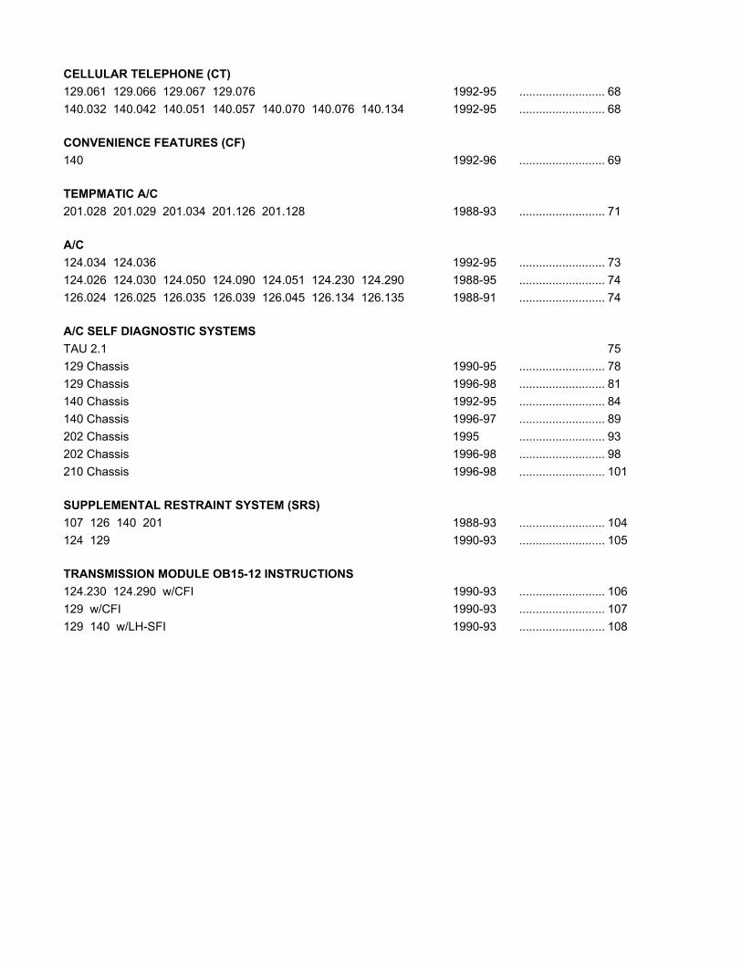
CELLULAR TELEPHONE (CT)129.061 129.066 129.067 129.076 1992-95 .......................................68140.032 140.042 140.051 140.057 140.070 140.076 140.134 1992-95 ...................................68
CONVENIENCE FEATURES (CF)140 1992-96 .......................................69
TEMPMATIC A/C201.028 201.029 201.034 201.126 201.128 1988-93 .......................................71
A/C124.034 124.036 1992-95 .......................................73124.026 124.030 124.050 124.090 124.051 124.230 124.290 1988-95 ...................................74126.024 126.025 126.035 126.039 126.045 126.134 126.135 1988-91 ...................................74
A/C SELF DIAGNOSTIC SYSTEMSTAU 2.1 75129 Chassis 1990-95 ...................................78129 Chassis 1996-98 ...................................81140 Chassis 1992-95 ...................................84140 Chassis 1996-97 ...................................89202 Chassis 1995 ...................................93202 Chassis 1996-98 ...................................98210 Chassis 1996-98 ...................................101
SUPPLEMENTAL RESTRAINT SYSTEM (SRS)107 126 140 201 1988-93 .......................................104124 129 1990-93 ...................................105
TRANSMISSION MODULE OB15-12 INSTRUCTIONS124.230 124.290 w/CFI 1990-93 .......................................106129 w/CFI 1990-93 ...................................107129 140 w/LH-SFI 1990-93 ...................................108
����1 ANALOG CODES CS1000 Code Scanner OB15-11
20
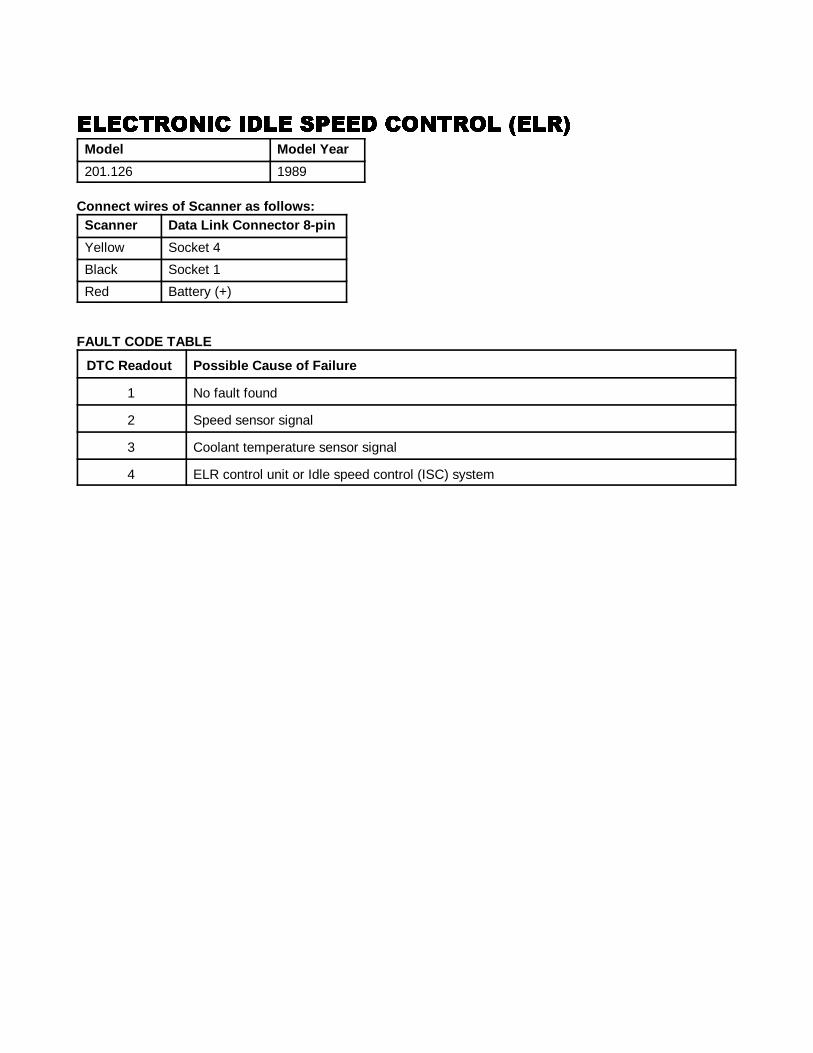
���������� ��� ���� ������� �������������� ��� ���� ������� �������������� ��� ���� ������� �������������� ��� ���� ������� ����Model Model Year
201.126 1989
Connect wires of Scanner as f ollows:Scanner Data Link Connector 8-pin
Yellow Socket 4
Black Socket 1
Red Battery (+)
FAULT CODE TABLE
DTC Readout Possible Cause of Failure
1 No fault found
2 Speed sensor signal
3 Coolant temperature sensor signal
4 ELR control unit or Idle speed control (ISC) system
����1 ANALOG CODES CS1000 Code Scanner OB15-11
21
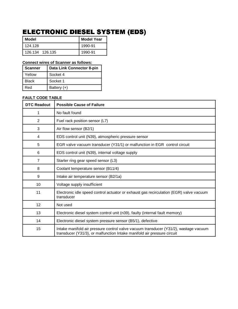
���������� ����� ������ ������������� ����� ������ ������������� ����� ������ ������������� ����� ������ ���Model Model Year
124.128 1990-91
126.134 126.135 1990-91
Connect wires of Scanner as f ollows:Scanner Data Link Connector 8-pin
Yellow Socket 4
Black Socket 1
Red Battery (+)
FAULT CODE TABLE
DTC Readout Possible Cause of Failure
1 No fault found
2 Fuel rack position sensor (L7)
3 Air flow sensor (B2/1)
4 EDS control unit (N39), atmospheric pressure sensor
5 EGR valve vacuum transducer (Y31/1) or malfunction in EGR control circuit
6 EDS control unit (N39), internal voltage supply
7 Starter ring gear speed sensor (L3)
8 Coolant temperature sensor (B11/4)
9 Intake air temperature sensor (B2/1a)
10 Voltage supply insufficient
11 Electronic idle speed control actuator or exhaust gas recirculation (EGR) valve vacuumtransducer
12 Not used
13 Electronic diesel system control unit (n39), faulty (internal fault memory)
14 Electronic diesel system pressure sensor (B5/1), defective
15 Intake manifold air pressure control valve vacuum transducer (Y31/2), wastage vacuumtransducer (Y31/3), or malfunction Intake manifold air pressure circuit
����1 ANALOG CODES CS1000 Code Scanner OB15-11
22
���������� ����� ������ ������������� ����� ������ ������������� ����� ������ ������������� ����� ������ ���Model Model Year
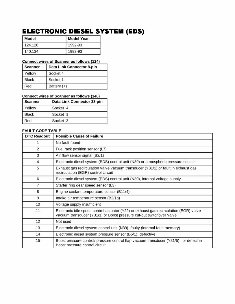
124.128 1992-93
140.134 1992-93
Connect wires of Scanner as f ollows ( 124)Scanner Data Link Connector 8-pin
Yellow Socket 4
Black Socket 1
Red Battery (+)
Connect wires of Scanner as f ollows ( 140)Scanner Data Link Connector 38-pin
Yellow Socket 4
Black Socket 1
Red Socket 3
FAULT CODE TABLEDTC Readout Possible Cause of Failure
1 No fault found
2 Fuel rack position sensor (L7)
3 Air flow sensor signal (B2/1)
4 Electronic diesel system (EDS) control unit (N39) or atmospheric pressure sensor
5 Exhaust gas recirculation valve vacuum transducer (Y31/1) or fault in exhaust gasrecirculation (EGR) control circuit
6 Electronic diesel system (EDS) control unit (N39), internal voltage supply
7 Starter ring gear speed sensor (L3)
8 Engine coolant temperature sensor (B11/4)
9 Intake air temperature sensor (B2/1a)
10 Voltage supply insufficient
11 Electronic idle speed control actuator (Y22) or exhaust gas recirculation (EGR) valvevacuum transducer (Y31/1) or Boost pressure cut-out switchover valve
12 Not used
13 Electronic diesel system control unit (N39), faulty (internal fault memory)
14 Electronic diesel system pressure sensor (B5/1), defective
15 Boost pressure control/ pressure control flap vacuum transducer (Y31/5) , or defect inBoost pressure control circuit.
����1 ANALOG CODES CS1000 Code Scanner OB15-11
23
���������� ���� ��������� ������ �������������� ���� ��������� ������ �������������� ���� ��������� ������ �������������� ���� ��������� ������ ����
Model Model Year
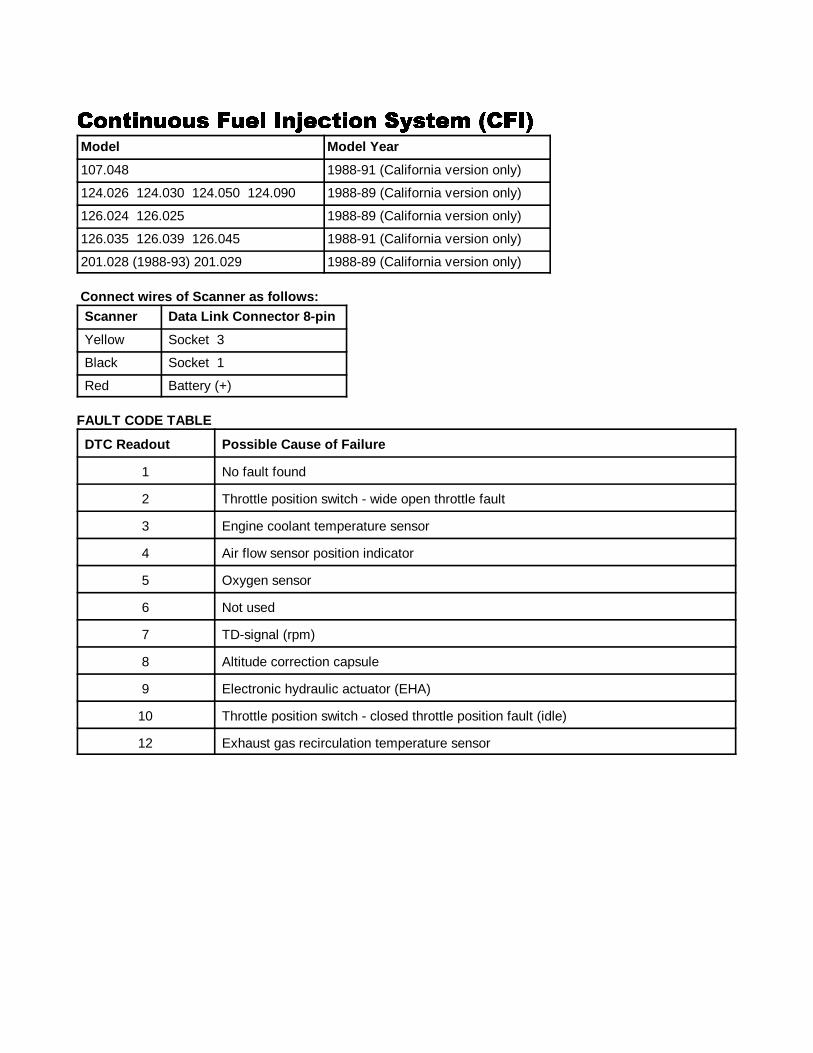
107.048 1988-91 (California version only)
124.026 124.030 124.050 124.090 1988-89 (California version only)
126.024 126.025 1988-89 (California version only)
126.035 126.039 126.045 1988-91 (California version only)
201.028 (1988-93) 201.029 1988-89 (California version only)
Connect wires of Scanner as f ollows:Scanner Data Link Connector 8-pin
Yellow Socket 3
Black Socket 1
Red Battery (+)
FAULT CODE TABLE
DTC Readout Possible Cause of Failure
1 No fault found
2 Throttle position switch - wide open throttle fault
3 Engine coolant temperature sensor
4 Air flow sensor position indicator
5 Oxygen sensor
6 Not used
7 TD-signal (rpm)
8 Altitude correction capsule
9 Electronic hydraulic actuator (EHA)
10 Throttle position switch - closed throttle position fault (idle)
12 Exhaust gas recirculation temperature sensor
����1 ANALOG CODES CS1000 Code Scanner OB15-11
24
���������� ���� ��������� ������ �������������� ���� ��������� ������ �������������� ���� ��������� ������ �������������� ���� ��������� ������ ����
Models Model Years
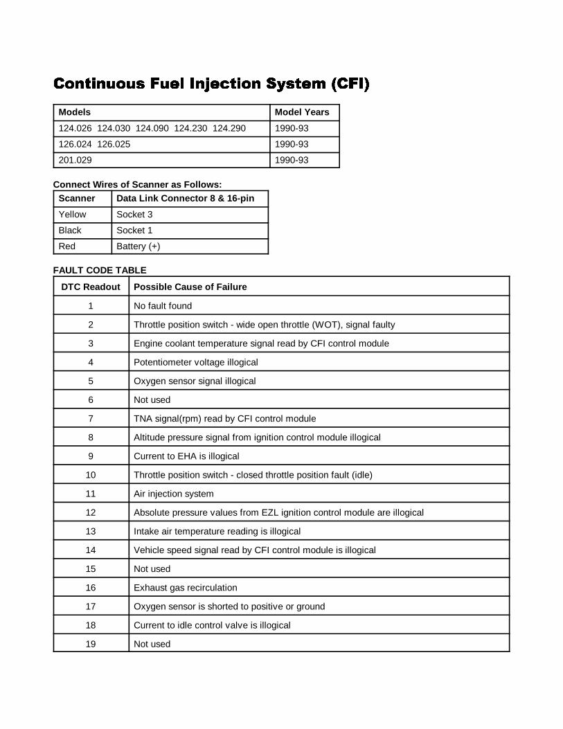
124.026 124.030 124.090 124.230 124.290 1990-93
126.024 126.025 1990-93
201.029 1990-93
Connect Wires of Scanner as Follows:Scanner Data Link Connector 8 & 16-pin
Yellow Socket 3
Black Socket 1
Red Battery (+)
FAULT CODE TABLE
DTC Readout Possible Cause of Failure
1 No fault found
2 Throttle position switch - wide open throttle (WOT), signal faulty
3 Engine coolant temperature signal read by CFI control module
4 Potentiometer voltage illogical
5 Oxygen sensor signal illogical
6 Not used
7 TNA signal(rpm) read by CFI control module
8 Altitude pressure signal from ignition control module illogical
9 Current to EHA is illogical
10 Throttle position switch - closed throttle position fault (idle)
11 Air injection system
12 Absolute pressure values from EZL ignition control module are illogical
13 Intake air temperature reading is illogical
14 Vehicle speed signal read by CFI control module is illogical
15 Not used
16 Exhaust gas recirculation
17 Oxygen sensor is shorted to positive or ground
18 Current to idle control valve is illogical
19 Not used
����1 ANALOG CODES CS1000 Code Scanner OB15-11
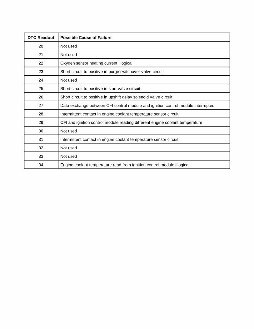
DTC Readout Possible Cause of Failure
25
20 Not used
21 Not used
22 Oxygen sensor heating current illogical
23 Short circuit to positive in purge switchover valve circuit
24 Not used
25 Short circuit to positive in start valve circuit
26 Short circuit to positive in upshift delay solenoid valve circuit
27 Data exchange between CFI control module and ignition control module interrupted
28 Intermittent contact in engine coolant temperature sensor circuit
29 CFI and ignition control module reading different engine coolant temperature
30 Not used
31 Intermittent contact in engine coolant temperature sensor circuit
32 Not used
33 Not used
34 Engine coolant temperature read from ignition control module illogical

����1 ANALOG CODES CS1000 Code Scanner OB15-11
26
���������� ���� ��������� ������ �������������� ���� ��������� ������ �������������� ���� ��������� ������ �������������� ���� ��������� ������ ����
Models Model Years
124.051 129.061 1990-93
129.066 1990-92
Connect wires of Scanner as f ollows:
Scanner Data Link Connector 16-pin
Yellow Socket 3
Black Socket 1
Red Socket 16
FAULT CODE TABLE
DTC Readout Possible Cause of Failure
1 No fault found
2 Throttle position switch - wide open throttle fault (WOT), signal faulty
3 Engine coolant temperature in CFI control module illogical
4 Air flow sensor position indicator potentiometer current illogical
5 Oxygen sensor signal illogical
6 Not used
7 TNA- signal (rpm) at CFI control module illogical
8 Altitude correction signal from ignition control module
9 Current to EHA is illogical
10 Throttle position switch - closed throttle position fault (idle)
11 Air injection system, open or short circuit
12 Absolute pressure values from ignition control module illogical
13 Intake air temperature illogical
14 Speed signal at CFI control module illogical
15 Not used
16 Exhaust gas recirculation switchover valve, open or short circuit
17 Oxygen sensor signal wire shorted to positive or ground
18 Current to idle control valve is illogical

����1 ANALOG CODES CS1000 Code Scanner OB15-11
DTC Readout Possible Cause of Failure
27
19 Not used
20 Not used
21 Not used
22 Oxygen sensor heater voltage illogical
23 Short to positive in purge switchover valve circuit
24 Not used
25 Short circuit to positive in start valve circuit
26 Short circuit to positive in upshift delay solenoid valve circuit
27 Data exchange between CFI control module and ignition control module
28 Intermittent contact in engine coolant temperature sensor circuit
29 CFI and ignition control module reading different engine coolant temperature
30 Not used
31 Intermittent contact in engine coolant temperature sensor circuit
32 Not used
33 Not used
34 Engine coolant temperature read from ignition control module illogical
www.mercedescodereader.com

����1 ANALOG CODES CS1000 Code Scanner OB15-11
28
���������� ���� ��������� ������ ��� ��������������������� ���� ��������� ������ ��� ��������������������� ���� ��������� ������ ��� ��������������������� ���� ��������� ������ ��� �����������
Models Model Years
124.026 124.030 124.090 124.230 124.290 129.066 201.029 1990-92
Connect wires of Scanner as f ollows
Scanner Data Link Connector 16-pin
Yellow Socket 14
Black Socket 1
Red Socket 16
FAULT CODE TABLE
DTC Readout Possible Cause of Failure
1 No fault found
2 Fuel pump relay (circuit 87) not functioning
3 TN/TD signal (RPM) interrupted
4 Output for oxygen sensor heater control defective
5 Output for air injection pump control defective
6 Output for kickdown switch control defective
7 Not used
8 Engine coolant temperature sensor signal out of range
9 Circuit 50 failure
10 Output failure of the start valve
11 A/C compressor engagement signal missing (87Z)
12 Output for A/C compressor control defective
13 Excessive A/C compressor clutch slippage
14 Vehicle speed signal illogical
15 Short circuit detected in fuel primp circuit
����1 ANALOG CODES CS1000 Code Scanner OB15-11
29
�� �� �����!� �����"�#� ���� ��������� ������ ��$������ �� �����!� �����"�#� ���� ��������� ������ ��$������ �� �����!� �����"�#� ���� ��������� ������ ��$������ �� �����!� �����"�#� ���� ��������� ������ ��$����
Models Model Years
140.032 140.057 140.076 1992-93
124.034 124.036 1992-93
129.067 1992-95
140.042 140.043 140.051 1992-95
Connect wires of Scanner as f ollows
Scanner Data Link Connector 38-pin
Yellow Socket 4
Black Socket 1
Red Socket 3
FAULT CODE TABLE
DTC Readout Possible Cause of Failure
1 No fault found
2 Engine coolant temperature sensor circuit 1, open or short circuit.
3 Engine coolant temperature sensor circuit 2, open or short circuit.
4 Voltage at mass air sensor with hot wire circuit. Open or short circuit.
5 Not used
6 Not used
7 TNA-signal (rpm signal ) incorrect or open or short circuit.
8 Camshaft position sensor signal. Open or short circuit.
9 Starter signal (circuit 50) missing, open or short circuit.
10 Closed throttle position recognition from electronic accelerator control unit, shortcircuit.
11 Secondary air injection system, open or short circuit.
12 Burn-off control for mass air sensor with hot-wire, open or short circuit.
13 Intake air temperature sensor, open or short circuit.
14 Not used
15 Not used
16 Exhaust gas recirculation (EGR) switchover valve, open or short circuit.
����1 ANALOG CODES CS1000 Code Scanner OB15-11
DTC Readout Possible Cause of Failure
30
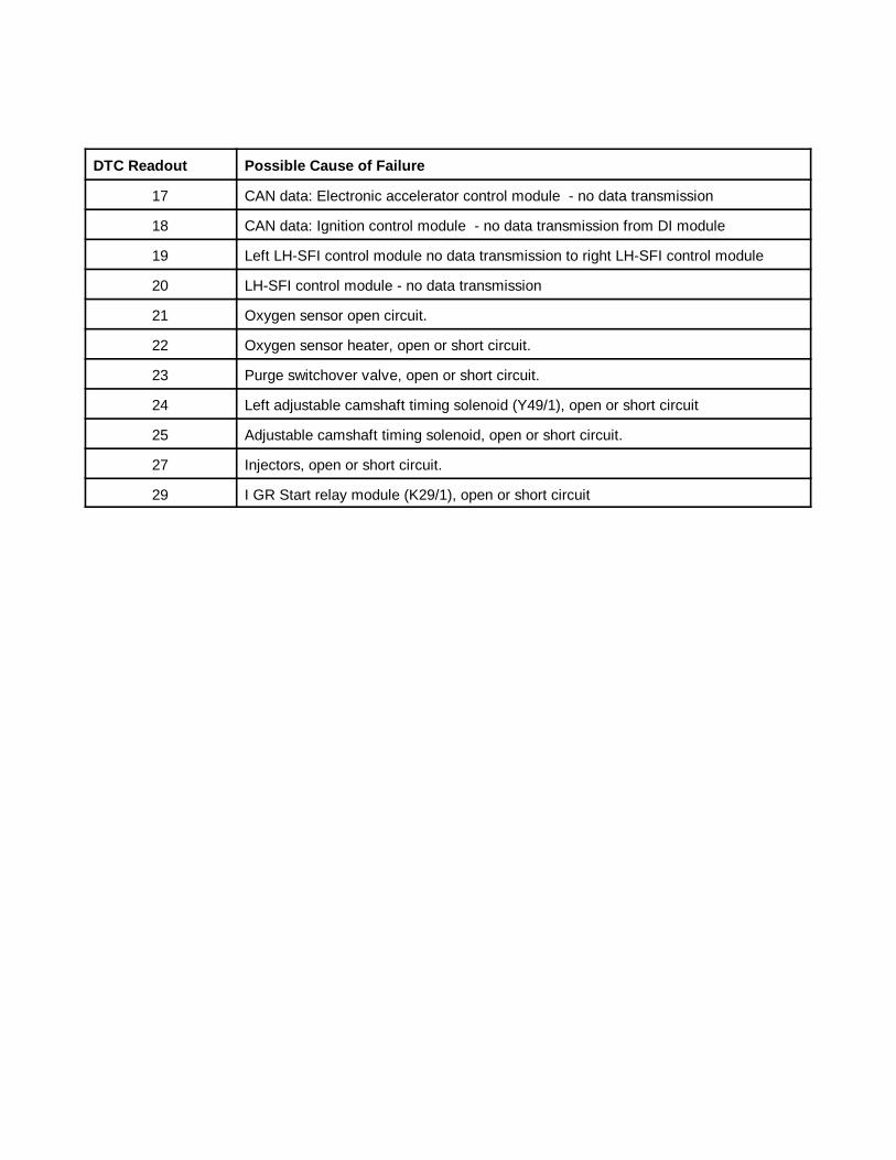
17 CAN data: Electronic accelerator control module - no data transmission
18 CAN data: Ignition control module - no data transmission from DI module
19 Left LH-SFI control module no data transmission to right LH-SFI control module
20 LH-SFI control module - no data transmission
21 Oxygen sensor open circuit.
22 Oxygen sensor heater, open or short circuit.
23 Purge switchover valve, open or short circuit.
24 Left adjustable camshaft timing solenoid (Y49/1), open or short circuit
25 Adjustable camshaft timing solenoid, open or short circuit.
27 Injectors, open or short circuit.
29 I GR Start relay module (K29/1), open or short circuit
����1 ANALOG CODES CS1000 Code Scanner OB15-11
31
��� �� �����!� �����"�#� ���� ��������� ��������� �� �����!� �����"�#� ���� ��������� ��������� �� �����!� �����"�#� ���� ��������� ��������� �� �����!� �����"�#� ���� ��������� ������
Engines Model Year
104 111 1993-97
Connect wires of Scanner as f ollows ( 124)
Scanner Data Link Connector 16-pin
Yellow Socket 8
Black Socket 1
Red Socket 16
Connect wires of Scanner as f ollows ( 202 129 140)
Scanner Data Link Connector 38-pin
Yellow Socket 4
Black Socket 1
Red Socket 3
FAULT CODE TABLE
DTC Readout Possible Cause of Failure
1 No fault found
2 Engine Coolant temperature sensor
3 Intake air temperature sensor
4 Hot film mass air flow sensor
5 CTP switch
6 Not used
7 Not used
8 Idle speed control (ISC) system at upper or lower control stop or CC or EA indicates "limphome" mode.
9 O2S 1 (before TWC) - voltage too high, circuit open or voltage implausible
10 O2S 2 (after TWC)voltage too high, circuit open or voltage implausible
11 O2S 1 heater (before TWC) - Current too high/low or short circuit.
12 O2S 2 heater (after TWC) - Current too high/low or short circuit.
13 O2S (Lambda) control system operating at rich or lean limit
14 Injector, cylinder 1
����1 ANALOG CODES CS1000 Code Scanner OB15-11
DTC Readout Possible Cause of Failure
32
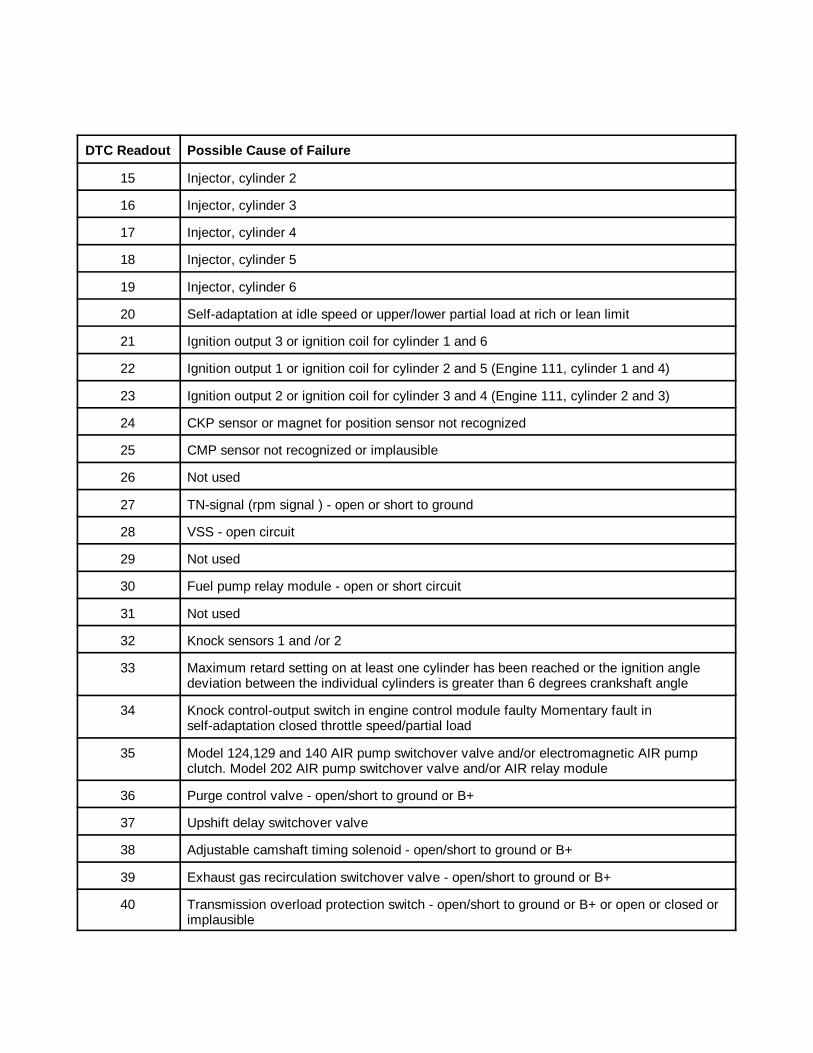
15 Injector, cylinder 2
16 Injector, cylinder 3
17 Injector, cylinder 4
18 Injector, cylinder 5
19 Injector, cylinder 6
20 Self-adaptation at idle speed or upper/lower partial load at rich or lean limit
21 Ignition output 3 or ignition coil for cylinder 1 and 6
22 Ignition output 1 or ignition coil for cylinder 2 and 5 (Engine 111, cylinder 1 and 4)
23 Ignition output 2 or ignition coil for cylinder 3 and 4 (Engine 111, cylinder 2 and 3)
24 CKP sensor or magnet for position sensor not recognized
25 CMP sensor not recognized or implausible
26 Not used
27 TN-signal (rpm signal ) - open or short to ground
28 VSS - open circuit
29 Not used
30 Fuel pump relay module - open or short circuit
31 Not used
32 Knock sensors 1 and /or 2
33 Maximum retard setting on at least one cylinder has been reached or the ignition angledeviation between the individual cylinders is greater than 6 degrees crankshaft angle
34 Knock control-output switch in engine control module faulty Momentary fault inself-adaptation closed throttle speed/partial load
35 Model 124,129 and 140 AIR pump switchover valve and/or electromagnetic AIR pumpclutch. Model 202 AIR pump switchover valve and/or AIR relay module
36 Purge control valve - open/short to ground or B+
37 Upshift delay switchover valve
38 Adjustable camshaft timing solenoid - open/short to ground or B+
39 Exhaust gas recirculation switchover valve - open/short to ground or B+
40 Transmission overload protection switch - open/short to ground or B+ or open or closed orimplausible
����1 ANALOG CODES CS1000 Code Scanner OB15-11
DTC Readout Possible Cause of Failure
33
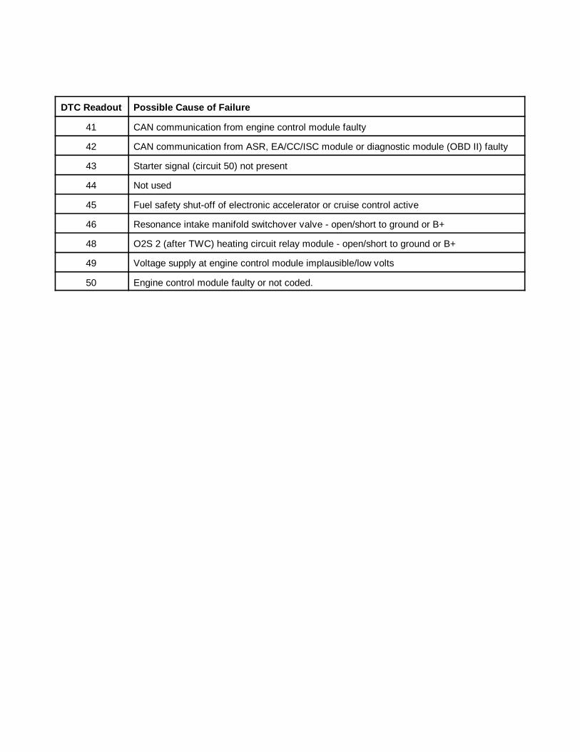
41 CAN communication from engine control module faulty
42 CAN communication from ASR, EA/CC/ISC module or diagnostic module (OBD II) faulty
43 Starter signal (circuit 50) not present
44 Not used
45 Fuel safety shut-off of electronic accelerator or cruise control active
46 Resonance intake manifold switchover valve - open/short to ground or B+
48 O2S 2 (after TWC) heating circuit relay module - open/short to ground or B+
49 Voltage supply at engine control module implausible/low volts
50 Engine control module faulty or not coded.

����1 ANALOG CODES CS1000 Code Scanner OB15-11
34
%!�� ��&��� %��%!�� ��&��� %��%!�� ��&��� %��%!�� ��&��� %��Models Model Years
124.034 124.036 1992-93
129.067 1992-95
140.032 140.042 140.043 140.051 140.057 140.076 1992-95
Connect wires of Scanner as f ollowsScanner Data Link Connector 38-pin
Yellow Socket 8
Black Socket 1
Red Socket 3
FAULT CODE TABLEDTC Readout Possible Cause of Failure
1 No fault found
2, 3, 4 Not used
5 Maximum permissible temperature in module box exceeded
6 Electromagnetic a/c compressor clutch blocked
7 Poly v-belt slipping
8 Voltage supply for LH-SFI control module interrupted
9 Voltage supply for LH-SFI control module interrupted
10 Voltage supply for LH-SFI control module interrupted Voltage supply for fuel injectors interrupted
11 Voltage supply for accessory equipment control module interrupted
12 Voltage supply for ABS control module, ABS/ASR control module or ASD controlmodule interrupted
13, 14 Not used
15 Voltage supply for kickdown valve interrupted
16 Voltage supply for electromagnetic a/c compressor clutch interrupted
17 Voltage supply for module box blower motor interrupted
����1 ANALOG CODES CS1000 Code Scanner OB15-11
35
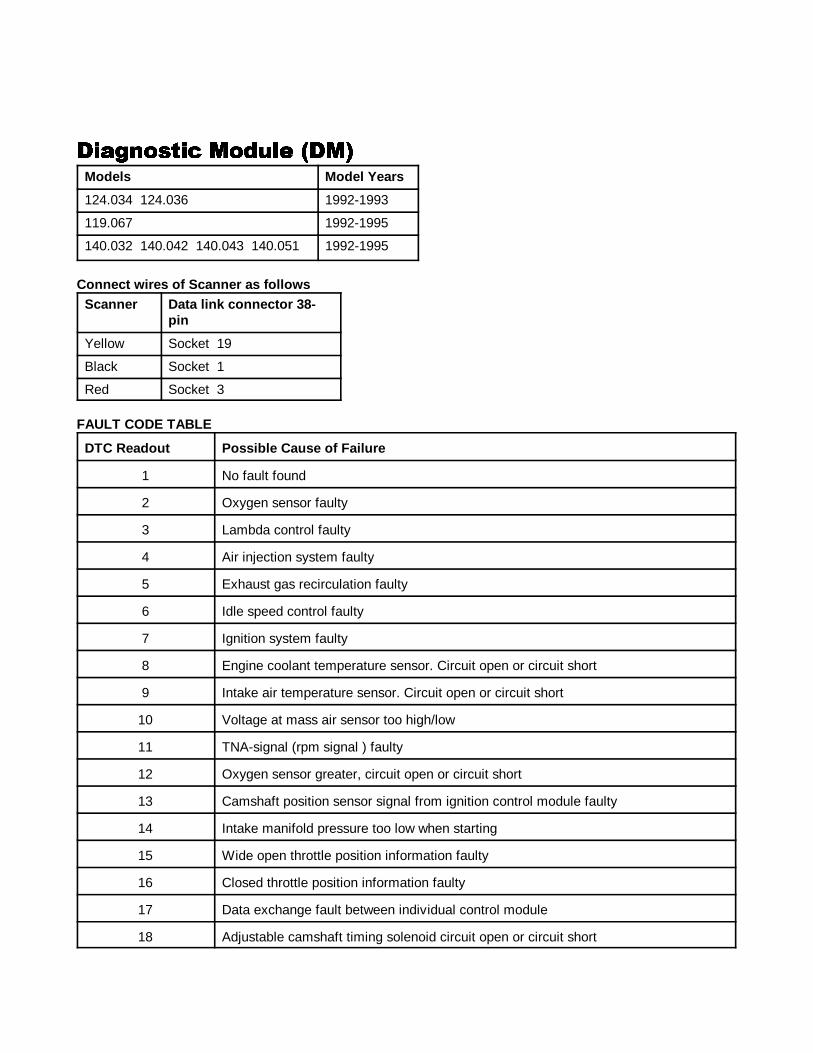
�!'������ ��&��� ���!'������ ��&��� ���!'������ ��&��� ���!'������ ��&��� ��Models Model Years
124.034 124.036 1992-1993
119.067 1992-1995
140.032 140.042 140.043 140.051 1992-1995
Connect wires of Scanner as f ollowsScanner Data link connector 38-
pin
Yellow Socket 19
Black Socket 1
Red Socket 3
FAULT CODE TABLE
DTC Readout Possible Cause of Failure
1 No fault found
2 Oxygen sensor faulty
3 Lambda control faulty
4 Air injection system faulty
5 Exhaust gas recirculation faulty
6 Idle speed control faulty
7 Ignition system faulty
8 Engine coolant temperature sensor. Circuit open or circuit short
9 Intake air temperature sensor. Circuit open or circuit short
10 Voltage at mass air sensor too high/low
11 TNA-signal (rpm signal ) faulty
12 Oxygen sensor greater, circuit open or circuit short
13 Camshaft position sensor signal from ignition control module faulty
14 Intake manifold pressure too low when starting
15 Wide open throttle position information faulty
16 Closed throttle position information faulty
17 Data exchange fault between individual control module
18 Adjustable camshaft timing solenoid circuit open or circuit short
����1 ANALOG CODES CS1000 Code Scanner OB15-11
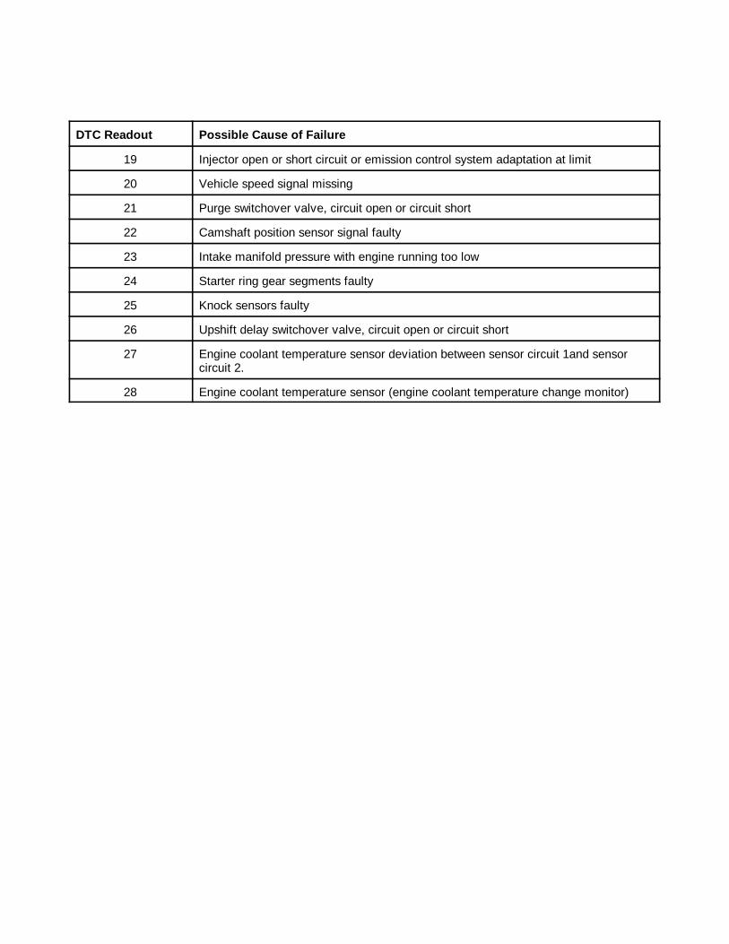
DTC Readout Possible Cause of Failure
36
19 Injector open or short circuit or emission control system adaptation at limit
20 Vehicle speed signal missing
21 Purge switchover valve, circuit open or circuit short
22 Camshaft position sensor signal faulty
23 Intake manifold pressure with engine running too low
24 Starter ring gear segments faulty
25 Knock sensors faulty
26 Upshift delay switchover valve, circuit open or circuit short
27 Engine coolant temperature sensor deviation between sensor circuit 1and sensorcircuit 2.
28 Engine coolant temperature sensor (engine coolant temperature change monitor)
����1 ANALOG CODES CS1000 Code Scanner OB15-11
37
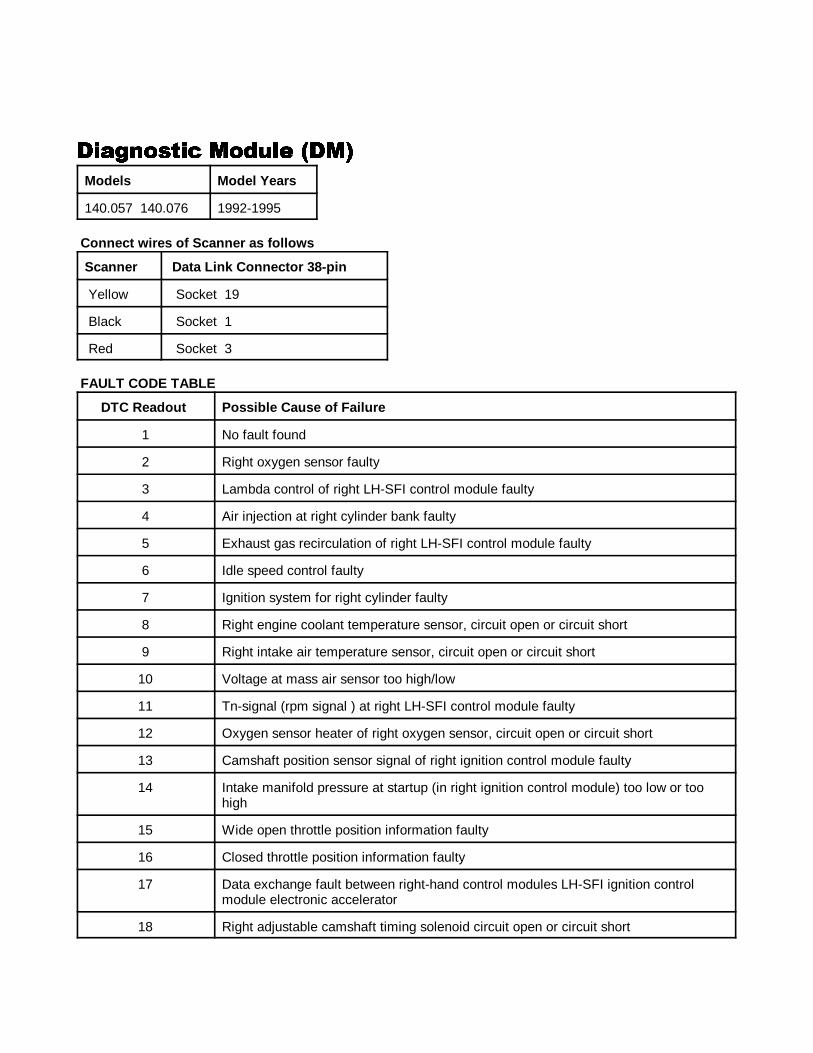
�!'������ ��&��� ���!'������ ��&��� ���!'������ ��&��� ���!'������ ��&��� ��
Models Model Years
140.057 140.076 1992-1995
Connect wires of Scanner as f ollows
Scanner Data Link Connector 38-pin
Yellow Socket 19
Black Socket 1
Red Socket 3
FAULT CODE TABLE
DTC Readout Possible Cause of Failure
1 No fault found
2 Right oxygen sensor faulty
3 Lambda control of right LH-SFI control module faulty
4 Air injection at right cylinder bank faulty
5 Exhaust gas recirculation of right LH-SFI control module faulty
6 Idle speed control faulty
7 Ignition system for right cylinder faulty
8 Right engine coolant temperature sensor, circuit open or circuit short
9 Right intake air temperature sensor, circuit open or circuit short
10 Voltage at mass air sensor too high/low
11 Tn-signal (rpm signal ) at right LH-SFI control module faulty
12 Oxygen sensor heater of right oxygen sensor, circuit open or circuit short
13 Camshaft position sensor signal of right ignition control module faulty
14 Intake manifold pressure at startup (in right ignition control module) too low or toohigh
15 Wide open throttle position information faulty
16 Closed throttle position information faulty
17 Data exchange fault between right-hand control modules LH-SFI ignition controlmodule electronic accelerator
18 Right adjustable camshaft timing solenoid circuit open or circuit short
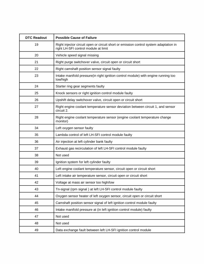
����1 ANALOG CODES CS1000 Code Scanner OB15-11
DTC Readout Possible Cause of Failure
38
19 Right injector circuit open or circuit short or emission control system adaptation inright LH-SFI control module at limit
20 Vehicle speed signal missing
21 Right purge switchover valve, circuit open or circuit short
22 Right camshaft position sensor signal faulty
23 Intake manifold pressure(in right ignition control module) with engine running toolow/high
24 Starter ring gear segments faulty
25 Knock sensors or right ignition control module faulty
26 Upshift delay switchover valve, circuit open or circuit short
27 Right engine coolant temperature sensor deviation between circuit 1, and sensorcircuit 2.
28 Right engine coolant temperature sensor (engine coolant temperature changemonitor)
34 Left oxygen sensor faulty
35 Lambda control of left LH-SFI control module faulty
36 Air injection at left cylinder bank faulty
37 Exhaust gas recirculation of left LH-SFI control module faulty
38 Not used
39 Ignition system for left cylinder faulty
40 Left engine coolant temperature sensor, circuit open or circuit short
41 Left intake air temperature sensor, circuit open or circuit short
42 Voltage at mass air sensor too high/low
43 Tn-signal (rpm signal ) at left LH-SFI control module faulty
44 Oxygen sensor heater of left oxygen sensor, circuit open or circuit short
45 Camshaft position sensor signal of left ignition control module faulty
46 Intake manifold pressure at (in left ignition control module) faulty
47 Not used
48 Not used
49 Data exchange fault between left LH-SFI ignition control module
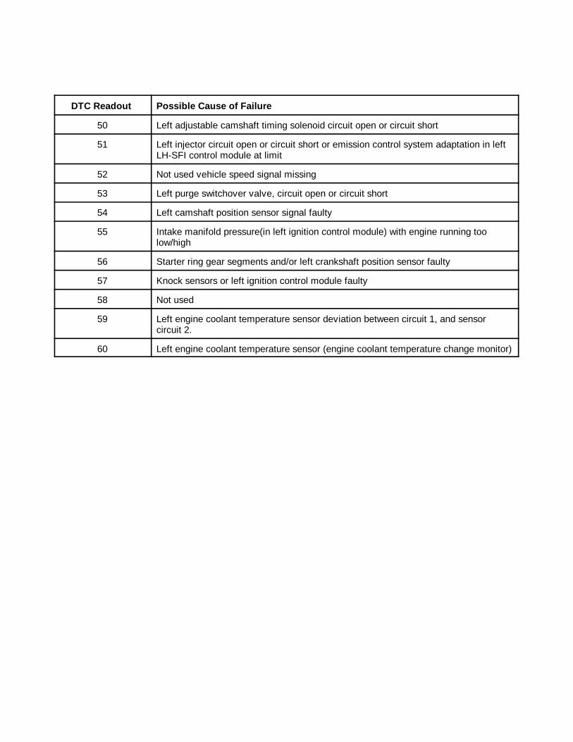
����1 ANALOG CODES CS1000 Code Scanner OB15-11
DTC Readout Possible Cause of Failure
39
50 Left adjustable camshaft timing solenoid circuit open or circuit short
51 Left injector circuit open or circuit short or emission control system adaptation in leftLH-SFI control module at limit
52 Not used vehicle speed signal missing
53 Left purge switchover valve, circuit open or circuit short
54 Left camshaft position sensor signal faulty
55 Intake manifold pressure(in left ignition control module) with engine running toolow/high
56 Starter ring gear segments and/or left crankshaft position sensor faulty
57 Knock sensors or left ignition control module faulty
58 Not used
59 Left engine coolant temperature sensor deviation between circuit 1, and sensorcircuit 2.
60 Left engine coolant temperature sensor (engine coolant temperature change monitor)
����1 ANALOG CODES CS1000 Code Scanner OB15-11
40
�!'������ ��&��� ���!'������ ��&��� ���!'������ ��&��� ���!'������ ��&��� ��Models Model Year
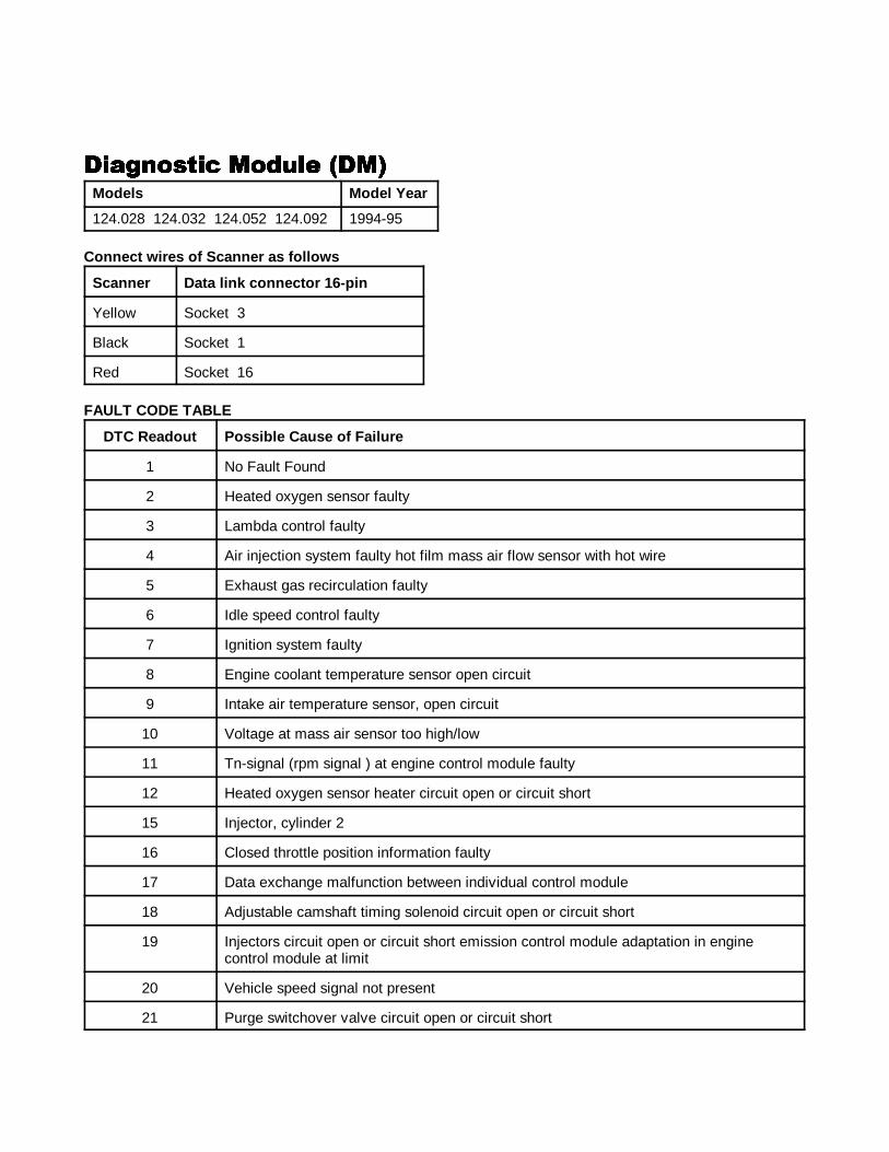
124.028 124.032 124.052 124.092 1994-95
Connect wires of Scanner as f ollows
Scanner Data link connector 16-pin
Yellow Socket 3
Black Socket 1
Red Socket 16
FAULT CODE TABLE
DTC Readout Possible Cause of Failure
1 No Fault Found
2 Heated oxygen sensor faulty
3 Lambda control faulty
4 Air injection system faulty hot film mass air flow sensor with hot wire
5 Exhaust gas recirculation faulty
6 Idle speed control faulty
7 Ignition system faulty
8 Engine coolant temperature sensor open circuit
9 Intake air temperature sensor, open circuit
10 Voltage at mass air sensor too high/low
11 Tn-signal (rpm signal ) at engine control module faulty
12 Heated oxygen sensor heater circuit open or circuit short
15 Injector, cylinder 2
16 Closed throttle position information faulty
17 Data exchange malfunction between individual control module
18 Adjustable camshaft timing solenoid circuit open or circuit short
19 Injectors circuit open or circuit short emission control module adaptation in enginecontrol module at limit
20 Vehicle speed signal not present
21 Purge switchover valve circuit open or circuit short
����1 ANALOG CODES CS1000 Code Scanner OB15-11
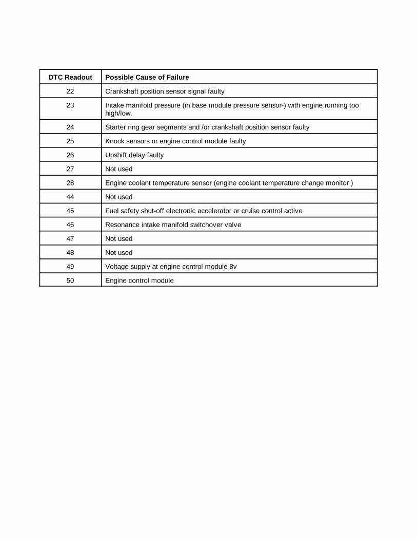
DTC Readout Possible Cause of Failure
41
22 Crankshaft position sensor signal faulty
23 Intake manifold pressure (in base module pressure sensor-) with engine running toohigh/low.
24 Starter ring gear segments and /or crankshaft position sensor faulty
25 Knock sensors or engine control module faulty
26 Upshift delay faulty
27 Not used
28 Engine coolant temperature sensor (engine coolant temperature change monitor )
44 Not used
45 Fuel safety shut-off electronic accelerator or cruise control active
46 Resonance intake manifold switchover valve
47 Not used
48 Not used
49 Voltage supply at engine control module 8v
50 Engine control module
����1 ANALOG CODES CS1000 Code Scanner OB15-11
42
���#�(���# �'������ �� ��$������#�(���# �'������ �� ��$������#�(���# �'������ �� ��$������#�(���# �'������ �� ��$���Model Model Years
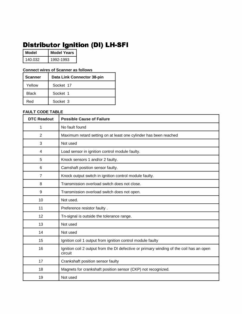
140.032 1992-1993
Connect wires of Scanner as f ollows
Scanner Data Link Connector 38-pin
Yellow Socket 17
Black Socket 1
Red Socket 3
FAULT CODE TABLE
DTC Readout Possible Cause of Failure
1 No fault found
2 Maximum retard setting on at least one cylinder has been reached
3 Not used
4 Load sensor in ignition control module faulty.
5 Knock sensors 1 and/or 2 faulty.
6 Camshaft position sensor faulty.
7 Knock output switch in ignition control module faulty.
8 Transmission overload switch does not close.
9 Transmission overload switch does not open.
10 Not used.
11 Preference resistor faulty .
12 Tn-signal is outside the tolerance range.
13 Not used
14 Not used
15 Ignition coil 1 output from ignition control module faulty
16 Ignition coil 2 output from the DI defective or primary winding of the coil has an opencircuit
17 Crankshaft position sensor faulty
18 Magnets for crankshaft position sensor (CKP) not recognized.
19 Not used
����1 ANALOG CODES CS1000 Code Scanner OB15-11
DTC Readout Possible Cause of Failure
43
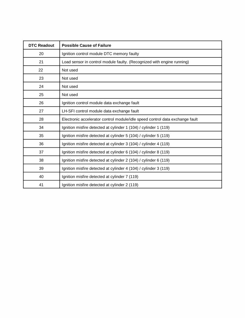
20 Ignition control module DTC memory faulty
21 Load sensor in control module faulty. (Recognized with engine running)
22 Not used
23 Not used
24 Not used
25 Not used
26 Ignition control module data exchange fault
27 LH-SFI control module data exchange fault
28 Electronic accelerator control module/idle speed control data exchange fault
34 Ignition misfire detected at cylinder 1 (104) / cylinder 1 (119)
35 Ignition misfire detected at cylinder 5 (104) / cylinder 5 (119)
36 Ignition misfire detected at cylinder 3 (104) / cylinder 4 (119)
37 Ignition misfire detected at cylinder 6 (104) / cylinder 8 (119)
38 Ignition misfire detected at cylinder 2 (104) / cylinder 6 (119)
39 Ignition misfire detected at cylinder 4 (104) / cylinder 3 (119)
40 Ignition misfire detected at cylinder 7 (119)
41 Ignition misfire detected at cylinder 2 (119)
����1 ANALOG CODES CS1000 Code Scanner OB15-11
44
���#�(���# �'������ �����#�(���# �'������ �����#�(���# �'������ �����#�(���# �'������ ��Model Model Years
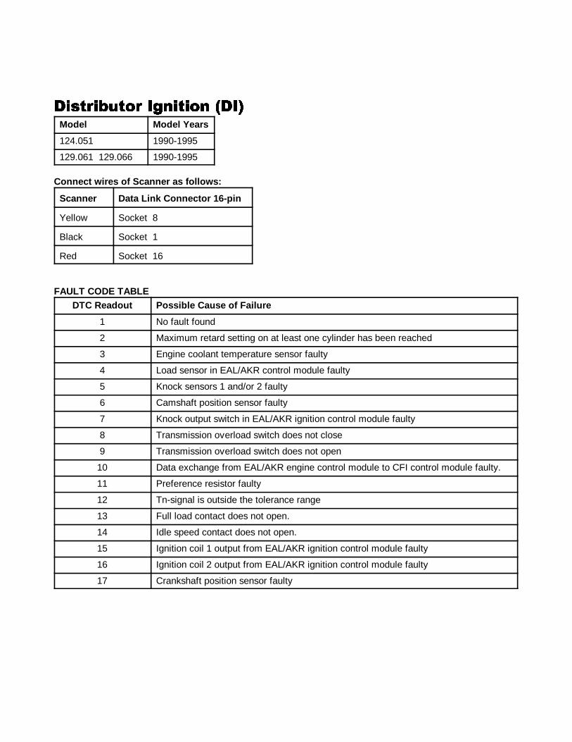
124.051 1990-1995
129.061 129.066 1990-1995
Connect wires of Scanner as f ollows:
Scanner Data Link Connector 16-pin
Yellow Socket 8
Black Socket 1
Red Socket 16
FAULT CODE TABLEDTC Readout Possible Cause of Failure
1 No fault found
2 Maximum retard setting on at least one cylinder has been reached
3 Engine coolant temperature sensor faulty
4 Load sensor in EAL/AKR control module faulty
5 Knock sensors 1 and/or 2 faulty
6 Camshaft position sensor faulty
7 Knock output switch in EAL/AKR ignition control module faulty
8 Transmission overload switch does not close
9 Transmission overload switch does not open
10 Data exchange from EAL/AKR engine control module to CFI control module faulty.
11 Preference resistor faulty
12 Tn-signal is outside the tolerance range
13 Full load contact does not open.
14 Idle speed contact does not open.
15 Ignition coil 1 output from EAL/AKR ignition control module faulty
16 Ignition coil 2 output from EAL/AKR ignition control module faulty
17 Crankshaft position sensor faulty
����1 ANALOG CODES CS1000 Code Scanner OB15-11
45
���#�(���# �'������ �����#�(���# �'������ �����#�(���# �'������ �����#�(���# �'������ ��Models Model Years
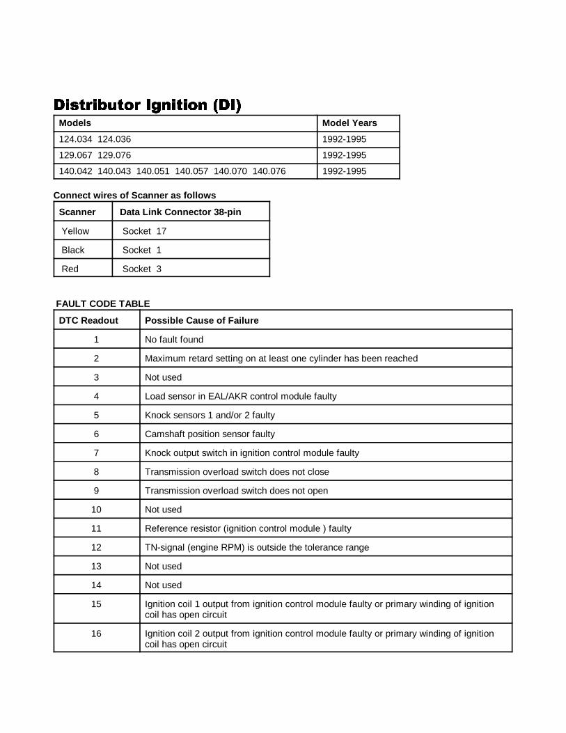
124.034 124.036 1992-1995
129.067 129.076 1992-1995
140.042 140.043 140.051 140.057 140.070 140.076 1992-1995
Connect wires of Scanner as f ollows
Scanner Data Link Connector 38-pin
Yellow Socket 17
Black Socket 1
Red Socket 3
FAULT CODE TABLE
DTC Readout Possible Cause of Failure
1 No fault found
2 Maximum retard setting on at least one cylinder has been reached
3 Not used
4 Load sensor in EAL/AKR control module faulty
5 Knock sensors 1 and/or 2 faulty
6 Camshaft position sensor faulty
7 Knock output switch in ignition control module faulty
8 Transmission overload switch does not close
9 Transmission overload switch does not open
10 Not used
11 Reference resistor (ignition control module ) faulty
12 TN-signal (engine RPM) is outside the tolerance range
13 Not used
14 Not used
15 Ignition coil 1 output from ignition control module faulty or primary winding of ignitioncoil has open circuit
16 Ignition coil 2 output from ignition control module faulty or primary winding of ignitioncoil has open circuit

����1 ANALOG CODES CS1000 Code Scanner OB15-11
DTC Readout Possible Cause of Failure
46
17 Crankshaft position sensor faulty
18 Magnets for crankshaft position sensor not recognized
19 Ground, Coding from Left EZL/AKR Ignition Control Module Not Present
20 Ignition control module DTC memory faulty
21 Load sensor in control module faulty. (recognized with engine running)
22 Not used
23 Not used
24 Not used
25 Not used
26 Ignition control module data exchange fault
27 Control module data exchange fault
28 Electronic accelerator control module/idle speed control data exchange fault
����1 ANALOG CODES CS1000 Code Scanner OB15-11
47
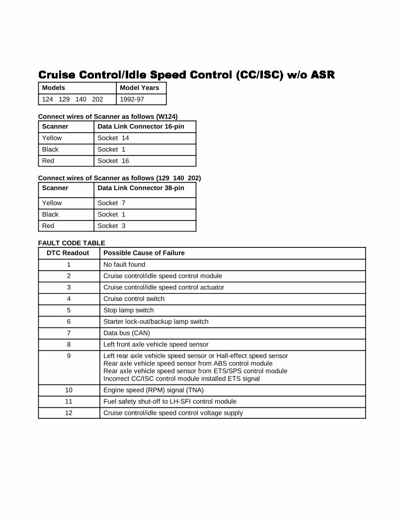
�#���� ����#��)�&�� �"��& ����#�� ��)���� *)� ����#���� ����#��)�&�� �"��& ����#�� ��)���� *)� ����#���� ����#��)�&�� �"��& ����#�� ��)���� *)� ����#���� ����#��)�&�� �"��& ����#�� ��)���� *)� ���Models Model Years
124 129 140 202 1992-97
Connect wires of Scanner as f ollows (W 124)Scanner Data Link Connector 16-pin
Yellow Socket 14
Black Socket 1
Red Socket 16
Connect wires of Scanner as f ollows ( 129 140 202)Scanner Data Link Connector 38-pin
Yellow Socket 7
Black Socket 1
Red Socket 3
FAULT CODE TABLE DTC Readout Possible Cause of Failure
1 No fault found
2 Cruise control/idle speed control module
3 Cruise control/idle speed control actuator
4 Cruise control switch
5 Stop lamp switch
6 Starter lock-out/backup lamp switch
7 Data bus (CAN)
8 Left front axle vehicle speed sensor
9 Left rear axle vehicle speed sensor or Hall-effect speed sensorRear axle vehicle speed sensor from ABS control module Rear axle vehicle speed sensor from ETS/SPS control module Incorrect CC/ISC control module installed ETS signal
10 Engine speed (RPM) signal (TNA)
11 Fuel safety shut-off to LH-SFI control module
12 Cruise control/idle speed control voltage supply
����1 ANALOG CODES CS1000 Code Scanner OB15-11
48
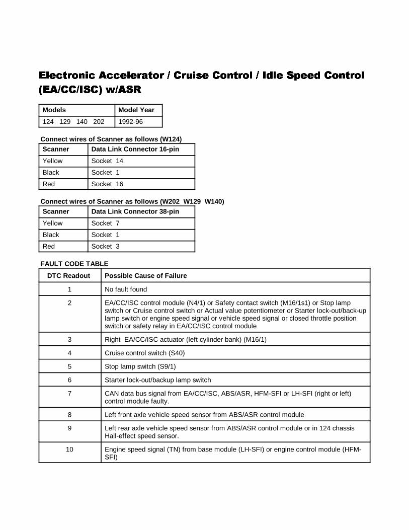
��������� ����������� ����� ������� ���� ����� ���������������� ����������� ����� ������� ���� ����� ���������������� ����������� ����� ������� ���� ����� ���������������� ����������� ����� ������� ���� ����� �������
��� �� ���� � ������ �� ���� � ������ �� ���� � ������ �� ���� � ���
Models Model Year
124 129 140 202 1992-96
Connect wires of Scanner as f ollows (W 124)Scanner Data Link Connector 16-pin
Yellow Socket 14
Black Socket 1
Red Socket 16
Connect wires of Scanner as f ollows (W 202 W129 W140)Scanner Data Link Connector 38-pin
Yellow Socket 7
Black Socket 1
Red Socket 3
FAULT CODE TABLE
DTC Readout Possible Cause of Failure
1 No fault found
2 EA/CC/ISC control module (N4/1) or Safety contact switch (M16/1s1) or Stop lampswitch or Cruise control switch or Actual value potentiometer or Starter lock-out/back-uplamp switch or engine speed signal or vehicle speed signal or closed throttle positionswitch or safety relay in EA/CC/ISC control module
3 Right EA/CC/ISC actuator (left cylinder bank) (M16/1)
4 Cruise control switch (S40)
5 Stop lamp switch (S9/1)
6 Starter lock-out/backup lamp switch
7 CAN data bus signal from EA/CC/ISC, ABS/ASR, HFM-SFI or LH-SFI (right or left)control module faulty.
8 Left front axle vehicle speed sensor from ABS/ASR control module
9 Left rear axle vehicle speed sensor from ABS/ASR control module or in 124 chassisHall-effect speed sensor.
10 Engine speed signal (TN) from base module (LH-SFI) or engine control module (HFM-SFI)
����1 ANALOG CODES CS1000 Code Scanner OB15-11
49
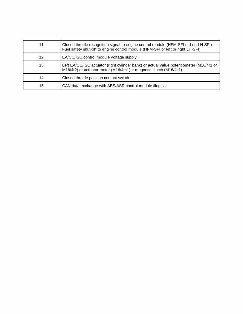
11 Closed throttle recognition signal to engine control module (HFM-SFI or Left LH-SFI)Fuel safety shut-off to engine control module (HFM-SFI or left or right LH-SFI)
12 EA/CC/ISC control module voltage supply
13 Left EA/CC/ISC actuator (right cylinder bank) or actual value potentiometer (M16/4r1 orM16/4r2) or actuator motor (M16/4m1)or magnetic clutch (M16/4k1).
14 Closed throttle position contact switch
15 CAN data exchange with ABS/ASR control module illogical
����1 ANALOG CODES CS1000 Code Scanner OB15-11
50
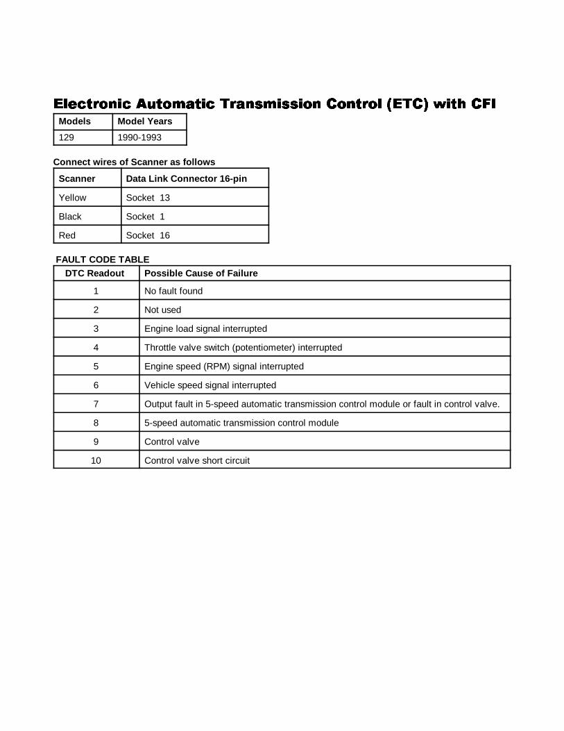
��������� �������� ���������� ������� ����� ��� ������������ �������� ���������� ������� ����� ��� ������������ �������� ���������� ������� ����� ��� ������������ �������� ���������� ������� ����� ��� ���Models Model Years
129 1990-1993
Connect wires of Scanner as f ollows
Scanner Data Link Connector 16-pin
Yellow Socket 13
Black Socket 1
Red Socket 16
FAULT CODE TABLEDTC Readout Possible Cause of Failure
1 No fault found
2 Not used
3 Engine load signal interrupted
4 Throttle valve switch (potentiometer) interrupted
5 Engine speed (RPM) signal interrupted
6 Vehicle speed signal interrupted
7 Output fault in 5-speed automatic transmission control module or fault in control valve.
8 5-speed automatic transmission control module
9 Control valve
10 Control valve short circuit
����1 ANALOG CODES CS1000 Code Scanner OB15-11
51
��������� �������� ���������� ������� ����� � ��������������� �������� ���������� ������� ����� � ��������������� �������� ���������� ������� ����� � ��������������� �������� ���������� ������� ����� � ������
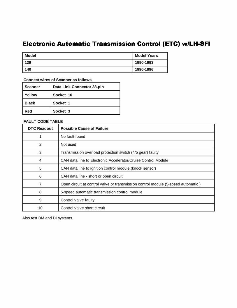
Model Model Years
129 1990-1993
140 1990-1996
Connect wires of Scanner as f ollows
Scanner Data Link Connector 38-pin
Yellow So cket 10
Black Socket 1
Red Socket 3
FAULT CODE TABLE
DTC Readout Possible Cause of Failure
1 No fault found
2 Not used
3 Transmission overload protection switch (4/5 gear) faulty
4 CAN data line to Electronic Accelerator/Cruise Control Module
5 CAN data line to ignition control module (knock sensor)
6 CAN data line - short or open circuit
7 Open circuit at control valve or transmission control module (5-speed automatic )
8 5-speed automatic transmission control module
9 Control valve faulty
10 Control valve short circuit
Also test BM and DI systems.
����1 ANALOG CODES CS1000 Code Scanner OB15-11
52
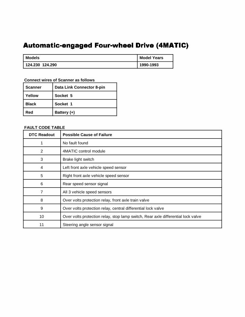
�����!���$��'!'�& ���#$*+��� #�,� -�����������!���$��'!'�& ���#$*+��� #�,� -�����������!���$��'!'�& ���#$*+��� #�,� -�����������!���$��'!'�& ���#$*+��� #�,� -������
Models Model Years
124.230 124.290 1990-1993
Connect wires of Scanner as f ollows
Scanner Data Link Connector 8-pin
Yellow So cket 5
Black Socket 1
Red Battery (+)
FAULT CODE TABLE
DTC Readout Possible Cause of Failure
1 No fault found
2 4MATIC control module
3 Brake light switch
4 Left front axle vehicle speed sensor
5 Right front axle vehicle speed sensor
6 Rear speed sensor signal
7 All 3 vehicle speed sensors
8 Over volts protection relay, front axle train valve
9 Over volts protection relay, central differential lock valve
10 Over volts protection relay, stop lamp switch, Rear axle differential lock valve
11 Steering angle sensor signal
����1 ANALOG CODES CS1000 Code Scanner OB15-11
53
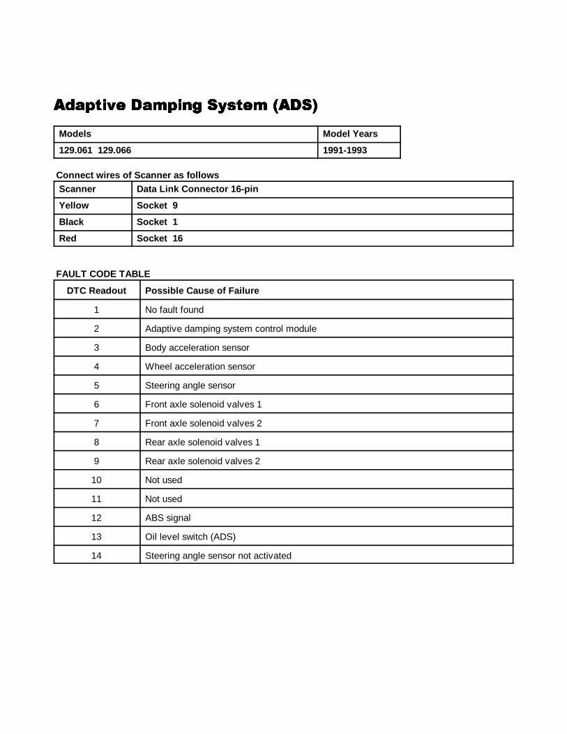
�&!"��,� !�"��' ������ ����&!"��,� !�"��' ������ ����&!"��,� !�"��' ������ ����&!"��,� !�"��' ������ ���
Models Model Years
129.061 129.066 1991-1993
Connect wires of Scanner as f ollowsScanner Data Link Connector 16-pin
Yellow So cket 9
Black Socket 1
Red Socket 16
FAULT CODE TABLE
DTC Readout Possible Cause of Failure
1 No fault found
2 Adaptive damping system control module
3 Body acceleration sensor
4 Wheel acceleration sensor
5 Steering angle sensor
6 Front axle solenoid valves 1
7 Front axle solenoid valves 2
8 Rear axle solenoid valves 1
9 Rear axle solenoid valves 2
10 Not used
11 Not used
12 ABS signal
13 Oil level switch (ADS)
14 Steering angle sensor not activated
����1 ANALOG CODES CS1000 Code Scanner OB15-11
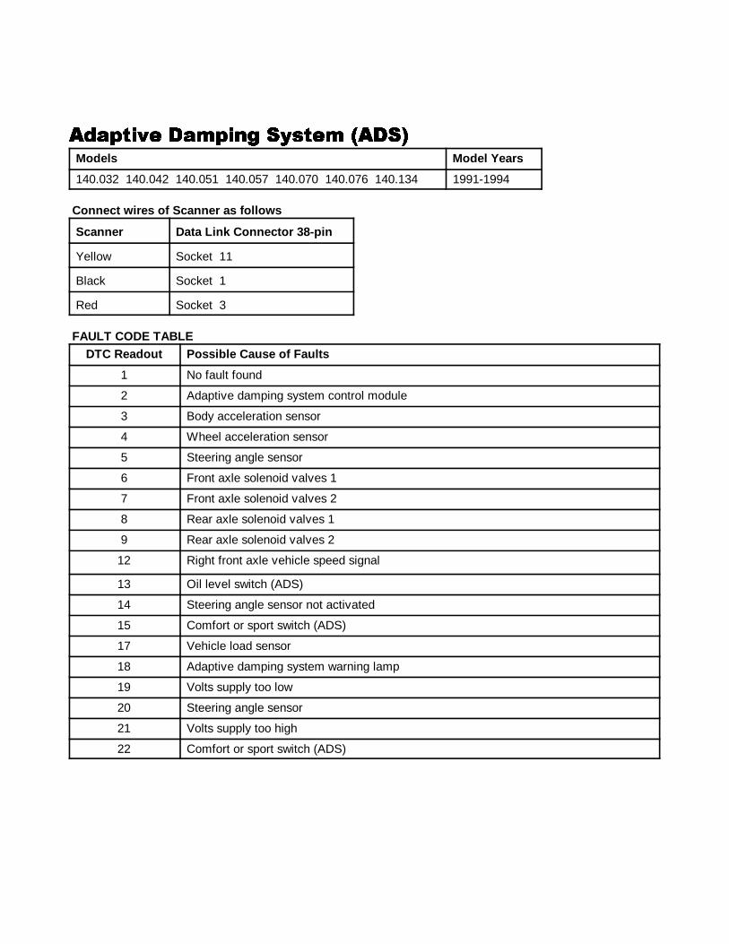
54
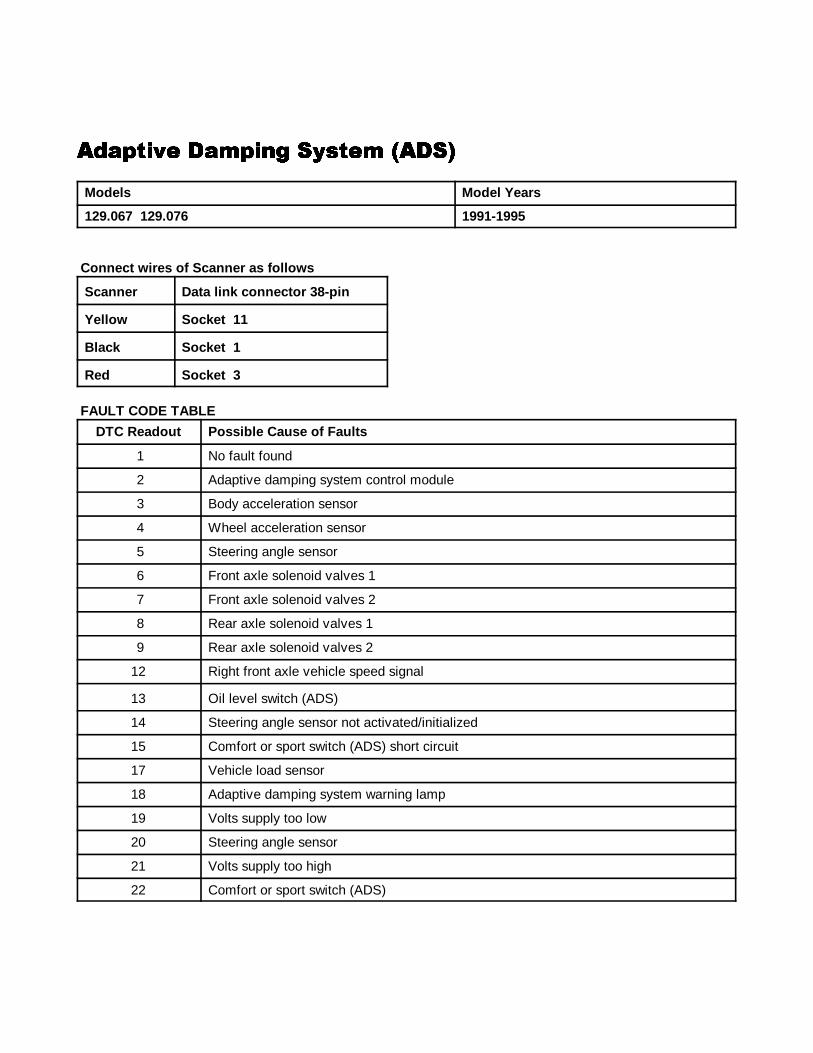
�&!"��,� !�"��' ������ ����&!"��,� !�"��' ������ ����&!"��,� !�"��' ������ ����&!"��,� !�"��' ������ ���
Models Model Years
129.067 129.076 1991-1995
Connect wires of Scanner as f ollows
Scanner Data link connector 38-pin
Yellow So cket 11
Black Socket 1
Red Socket 3
FAULT CODE TABLE
DTC Readout Possible Cause of Faults
1 No fault found
2 Adaptive damping system control module
3 Body acceleration sensor
4 Wheel acceleration sensor
5 Steering angle sensor
6 Front axle solenoid valves 1
7 Front axle solenoid valves 2
8 Rear axle solenoid valves 1
9 Rear axle solenoid valves 2
12 Right front axle vehicle speed signal
13 Oil level switch (ADS)
14 Steering angle sensor not activated/initialized
15 Comfort or sport switch (ADS) short circuit
17 Vehicle load sensor
18 Adaptive damping system warning lamp
19 Volts supply too low
20 Steering angle sensor
21 Volts supply too high
22 Comfort or sport switch (ADS)
����1 ANALOG CODES CS1000 Code Scanner OB15-11
55
�&!"��,� !�"��' ������ ����&!"��,� !�"��' ������ ����&!"��,� !�"��' ������ ����&!"��,� !�"��' ������ ���Models Model Years
140.032 140.042 140.051 140.057 140.070 140.076 140.134 1991-1994
Connect wires of Scanner as f ollows
Scanner Data Link Connector 38-pin
Yellow Socket 11
Black Socket 1
Red Socket 3
FAULT CODE TABLEDTC Readout Possible Cause of Faults
1 No fault found
2 Adaptive damping system control module
3 Body acceleration sensor
4 Wheel acceleration sensor
5 Steering angle sensor
6 Front axle solenoid valves 1
7 Front axle solenoid valves 2
8 Rear axle solenoid valves 1
9 Rear axle solenoid valves 2
12 Right front axle vehicle speed signal
13 Oil level switch (ADS)
14 Steering angle sensor not activated
15 Comfort or sport switch (ADS)
17 Vehicle load sensor
18 Adaptive damping system warning lamp
19 Volts supply too low
20 Steering angle sensor
21 Volts supply too high
22 Comfort or sport switch (ADS)
����1 ANALOG CODES CS1000 Code Scanner OB15-11
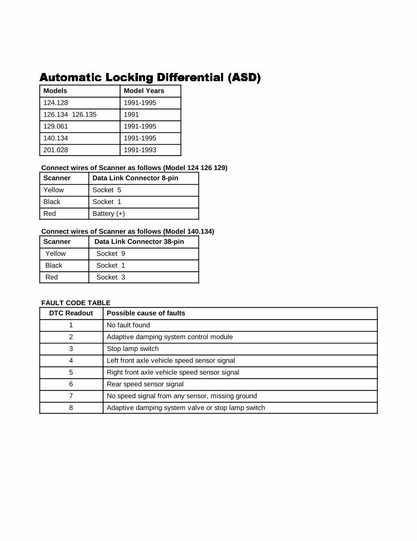
56
�����!��� ���.��' �//�#����!� ��������!��� ���.��' �//�#����!� ��������!��� ���.��' �//�#����!� ��������!��� ���.��' �//�#����!� ���Models Model Years
124.128 1991-1995
126.134 126.135 1991
129.061 1991-1995
140.134 1991-1995
201.028 1991-1993
Connect wires of Scanner as f ollows (Model 124 126 129)Scanner Data Link Connector 8-pin
Yellow Socket 5
Black Socket 1
Red Battery (+)
Connect wires of Scanner as f ollows (Model 140.134)Scanner Data Link Connector 38-pin
Yellow Socket 9
Black Socket 1
Red Socket 3
FAULT CODE TABLEDTC Readout Possible cause of faults
1 No fault found
2 Adaptive damping system control module
3 Stop lamp switch
4 Left front axle vehicle speed sensor signal
5 Right front axle vehicle speed sensor signal
6 Rear speed sensor signal
7 No speed signal from any sensor, missing ground
8 Adaptive damping system valve or stop lamp switch
����1 ANALOG CODES CS1000 Code Scanner OB15-11
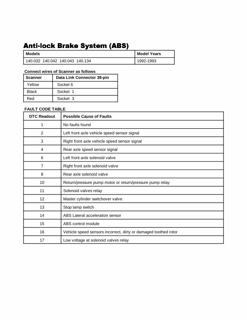
57
����$���. %#!.� ������ �%������$���. %#!.� ������ �%������$���. %#!.� ������ �%������$���. %#!.� ������ �%��
Models Model Years
140.032 140.042 140.043 140.134 1992-1993
Connect wires of Scanner as f ollowsScanner Data Link Connector 38-pin
Yellow Socket 6
Black Socket 1
Red Socket 3
FAULT CODE TABLE
DTC Readout Possible Cause of Faults
1 No faults found
2 Left front axle vehicle speed sensor signal
3 Right front axle vehicle speed sensor signal
4 Rear axle speed sensor signal
6 Left front axle solenoid valve
7 Right front axle solenoid valve
8 Rear axle solenoid valve
10 Return/pressure pump motor or return/pressure pump relay
11 Solenoid valves relay
12 Master cylinder switchover valve
13 Stop lamp switch
14 ABS Lateral acceleration sensor
15 ABS control module
16 Vehicle speed sensors incorrect, dirty or damaged toothed rotor
17 Low voltage at solenoid valves relay
����1 ANALOG CODES CS1000 Code Scanner OB15-11
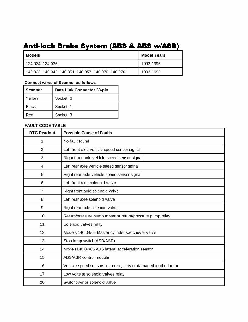
58
����$���. %#!.� ������ �%� 0 �%� *)��������$���. %#!.� ������ �%� 0 �%� *)��������$���. %#!.� ������ �%� 0 �%� *)��������$���. %#!.� ������ �%� 0 �%� *)����
Models Model Years
124.034 124.036 1992-1995
140.032 140.042 140.051 140.057 140.070 140.076 1992-1995
Connect wires of Scanner as f ollows
Scanner Data Link Connector 38-pin
Yellow Socket 6
Black Socket 1
Red Socket 3 FAULT CODE TABLE
DTC Readout Possible Cause of Faults
1 No fault found
2 Left front axle vehicle speed sensor signal
3 Right front axle vehicle speed sensor signal
4 Left rear axle vehicle speed sensor signal
5 Right rear axle vehicle speed sensor signal
6 Left front axle solenoid valve
7 Right front axle solenoid valve
8 Left rear axle solenoid valve
9 Right rear axle solenoid valve
10 Return/pressure pump motor or return/pressure pump relay
11 Solenoid valves relay
12 Models 140.04/05 Master cylinder switchover valve
13 Stop lamp switch(ASD/ASR)
14 Models140.04/05 ABS lateral acceleration sensor
15 ABS/ASR control module
16 Vehicle speed sensors incorrect, dirty or damaged toothed rotor
17 Low volts at solenoid valves relay
20 Switchover or solenoid valve
����1 ANALOG CODES CS1000 Code Scanner OB15-11
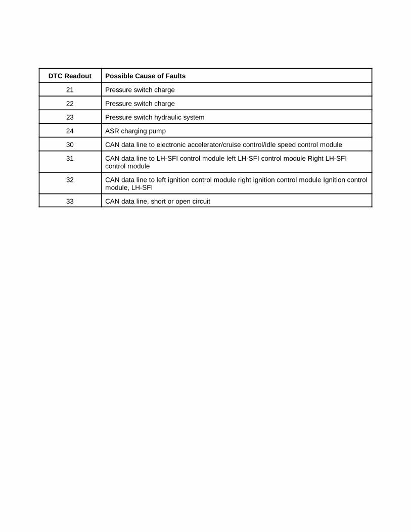
DTC Readout Possible Cause of Faults
59
21 Pressure switch charge
22 Pressure switch charge
23 Pressure switch hydraulic system
24 ASR charging pump
30 CAN data line to electronic accelerator/cruise control/idle speed control module
31 CAN data line to LH-SFI control module left LH-SFI control module Right LH-SFIcontrol module
32 CAN data line to left ignition control module right ignition control module Ignition controlmodule, LH-SFI
33 CAN data line, short or open circuit
����1 ANALOG CODES CS1000 Code Scanner OB15-11
60
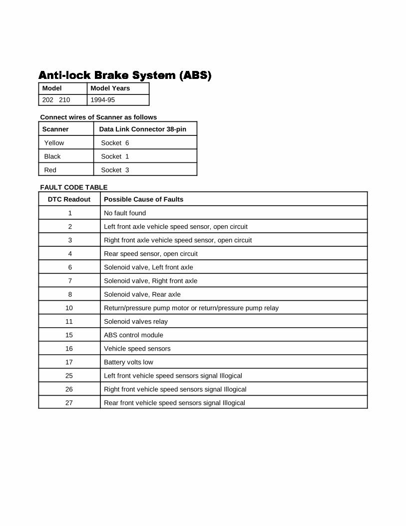
����$���. %#!.� ������ �%������$���. %#!.� ������ �%������$���. %#!.� ������ �%������$���. %#!.� ������ �%��
Model Model Years
202 210 1994-95
Connect wires of Scanner as f ollows
Scanner Data Link Connector 38-pin
Yellow Socket 6
Black Socket 1
Red Socket 3
FAULT CODE TABLE
DTC Readout Possible Cause of Faults
1 No fault found
2 Left front axle vehicle speed sensor, open circuit
3 Right front axle vehicle speed sensor, open circuit
4 Rear speed sensor, open circuit
6 Solenoid valve, Left front axle
7 Solenoid valve, Right front axle
8 Solenoid valve, Rear axle
10 Return/pressure pump motor or return/pressure pump relay
11 Solenoid valves relay
15 ABS control module
16 Vehicle speed sensors
17 Battery volts low
25 Left front vehicle speed sensors signal Illogical
26 Right front vehicle speed sensors signal Illogical
27 Rear front vehicle speed sensors signal Illogical
����1 ANALOG CODES CS1000 Code Scanner OB15-11
61
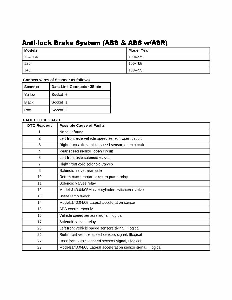
����$���. %#!.� ������ �%� 0 �%� *)��������$���. %#!.� ������ �%� 0 �%� *)��������$���. %#!.� ������ �%� 0 �%� *)��������$���. %#!.� ������ �%� 0 �%� *)����Models Model Year
124.034 1994-95
129 1994-95
140 1994-95
Connect wires of Scanner as f ollows
Scanner Data Link Connector 38-pin
Yellow Socket 6
Black Socket 1
Red Socket 3
FAULT CODE TABLEDTC Readout Possible Cause of Faults
1 No fault found
2 Left front axle vehicle speed sensor, open circuit
3 Right front axle vehicle speed sensor, open circuit
4 Rear speed sensor, open circuit
6 Left front axle solenoid valves
7 Right front axle solenoid valves
8 Solenoid valve, rear axle
10 Return pump motor or return pump relay
11 Solenoid valves relay
12 Models140.04/05Master cylinder switchover valve
13 Brake lamp switch
14 Models140.04/05 Lateral acceleration sensor
15 ABS control module
16 Vehicle speed sensors signal Illogical
17 Solenoid valves relay
25 Left front vehicle speed sensors signal, Illogical
26 Right front vehicle speed sensors signal, Illogical
27 Rear front vehicle speed sensors signal, Illogical
29 Models140.04/05 Lateral acceleration sensor signal, Illogical

����1 ANALOG CODES CS1000 Code Scanner OB15-11
62
�����#���� �#!����� ������� ���1 ���������#���� �#!����� ������� ���1 ���������#���� �#!����� ������� ���1 ���������#���� �#!����� ������� ���1 ����Models Model Years
129 140 202 1995
210 1995-96
Connect wires of Scanner as f ollows
Scanner Data Link Connector 38-pin
Yellow Socket 6
Black Socket 1
Red Socket 3
FAULT CODE TABLE
DTC Readout Possible Cause of Faults
1 No fault found
2 ASR/SPS or ETS/SPS control module
3 Left front axle VSS sensor, open circuit
4 Right front axle VSS sensor, open circuit
5 Left rear axle VSS sensor, open circuit
6 Right rear axle VSS sensor, open circuit
7 Left front axle VSS valves, illogical
8 Right front axle VSS valves illogical
9 Left rear axle VSS valve illogical
10 Right rear axle VSS valve illogical
11 VSS signal illogical
12 ASR/ETS hydraulic unit, solenoid valves relay
13 ASR/ETS hydraulic unit, Left front axle solenoid valves(hold)
14 ASR/ETS hydraulic unit, Left front axle solenoid valve(hold)
15 ASR/ETS hydraulic unit, right front axle solenoid valve (release)
16 ASR/ETS hydraulic unit, right front axle solenoid valve (release)
17 ASR/ETS hydraulic unit, left rear axle solenoid valve(hold)
18 ASR/ETS hydraulic unit, left rear axle solenoid valve (release)
����1 ANALOG CODES CS1000 Code Scanner OB15-11
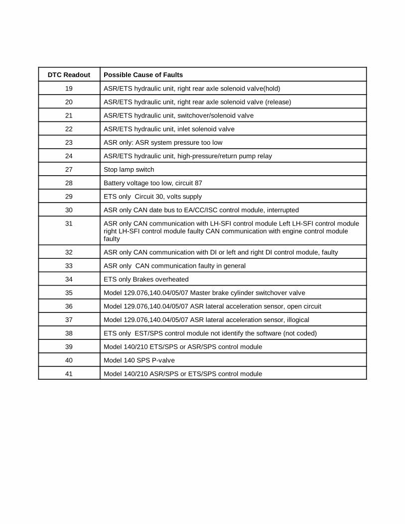
DTC Readout Possible Cause of Faults
63
19 ASR/ETS hydraulic unit, right rear axle solenoid valve(hold)
20 ASR/ETS hydraulic unit, right rear axle solenoid valve (release)
21 ASR/ETS hydraulic unit, switchover/solenoid valve
22 ASR/ETS hydraulic unit, inlet solenoid valve
23 ASR only: ASR system pressure too low
24 ASR/ETS hydraulic unit, high-pressure/return pump relay
27 Stop lamp switch
28 Battery voltage too low, circuit 87
29 ETS only Circuit 30, volts supply
30 ASR only CAN date bus to EA/CC/ISC control module, interrupted
31 ASR only CAN communication with LH-SFI control module Left LH-SFI control moduleright LH-SFI control module faulty CAN communication with engine control modulefaulty
32 ASR only CAN communication with DI or left and right DI control module, faulty
33 ASR only CAN communication faulty in general
34 ETS only Brakes overheated
35 Model 129.076,140.04/05/07 Master brake cylinder switchover valve
36 Model 129.076,140.04/05/07 ASR lateral acceleration sensor, open circuit
37 Model 129.076,140.04/05/07 ASR lateral acceleration sensor, illogical
38 ETS only EST/SPS control module not identify the software (not coded)
39 Model 140/210 ETS/SPS or ASR/SPS control module
40 Model 140 SPS P-valve
41 Model 140/210 ASR/SPS or ETS/SPS control module
����1 ANALOG CODES CS1000 Code Scanner OB15-11
64
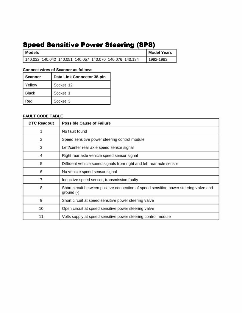
�"��& �������,� ��*�# ����#��' �����"��& �������,� ��*�# ����#��' �����"��& �������,� ��*�# ����#��' �����"��& �������,� ��*�# ����#��' ����
Models Model Years
140.032 140.042 140.051 140.057 140.070 140.076 140.134 1992-1993
Connect wires of Scanner as f ollows
Scanner Data Link Connector 38-pin
Yellow Socket 12
Black Socket 1
Red Socket 3
FAULT CODE TABLE
DTC Readout Possible Cause of Failure
1 No fault found
2 Speed sensitive power steering control module
3 Left/center rear axle speed sensor signal
4 Right rear axle vehicle speed sensor signal
5 Diffident vehicle speed signals from right and left rear axle sensor
6 No vehicle speed sensor signal
7 Inductive speed sensor, transmission faulty
8 Short circuit between positive connection of speed sensitive power steering valve andground (-)
9 Short circuit at speed sensitive power steering valve
10 Open circuit at speed sensitive power steering valve
11 Volts supply at speed sensitive power steering control module
����1 ANALOG CODES CS1000 Code Scanner OB15-11
65
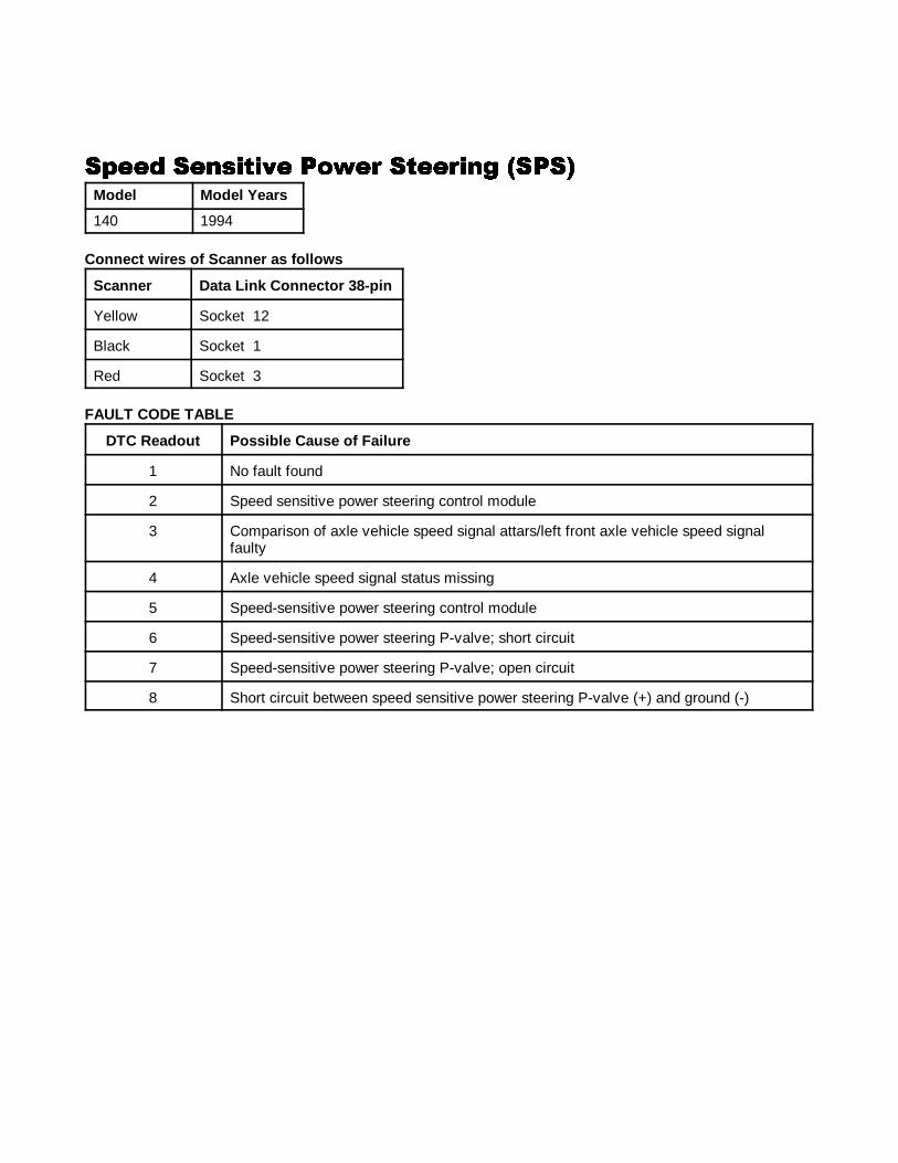
�"��& �������,� ��*�# ����#��' �����"��& �������,� ��*�# ����#��' �����"��& �������,� ��*�# ����#��' �����"��& �������,� ��*�# ����#��' ����
Model Model Years
140 1994
Connect wires of Scanner as f ollows
Scanner Data Link Connector 38-pin
Yellow Socket 12
Black Socket 1
Red Socket 3
FAULT CODE TABLE
DTC Readout Possible Cause of Failure
1 No fault found
2 Speed sensitive power steering control module
3 Comparison of axle vehicle speed signal attars/left front axle vehicle speed signalfaulty
4 Axle vehicle speed signal status missing
5 Speed-sensitive power steering control module
6 Speed-sensitive power steering P-valve; short circuit
7 Speed-sensitive power steering P-valve; open circuit
8 Short circuit between speed sensitive power steering P-valve (+) and ground (-)
����1 ANALOG CODES CS1000 Code Scanner OB15-11
66
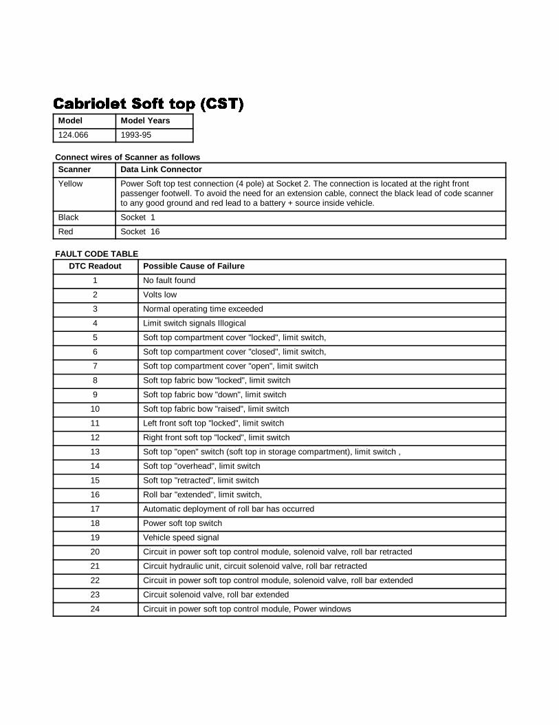
�!(#����� ��/� ��" �����!(#����� ��/� ��" �����!(#����� ��/� ��" �����!(#����� ��/� ��" ����Model Model Years
124.066 1993-95
Connect wires of Scanner as followsScanner Data Link Connector
Yellow Power Soft top test connection (4 pole) at Socket 2. The connection is located at the right frontpassenger footwell. To avoid the need for an extension cable, connect the black lead of code scannerto any good ground and red lead to a battery + source inside vehicle.
Black Socket 1
Red Socket 16
FAULT CODE TABLEDTC Readout Possible Cause of Failure
1 No fault found
2 Volts low
3 Normal operating time exceeded
4 Limit switch signals Illogical
5 Soft top compartment cover "locked", limit switch,
6 Soft top compartment cover "closed", limit switch,
7 Soft top compartment cover "open", limit switch
8 Soft top fabric bow "locked", limit switch
9 Soft top fabric bow "down", limit switch
10 Soft top fabric bow "raised", limit switch
11 Left front soft top "locked", limit switch
12 Right front soft top "locked", limit switch
13 Soft top "open" switch (soft top in storage compartment), limit switch ,
14 Soft top "overhead", limit switch
15 Soft top "retracted", limit switch
16 Roll bar "extended", limit switch,
17 Automatic deployment of roll bar has occurred
18 Power soft top switch
19 Vehicle speed signal
20 Circuit in power soft top control module, solenoid valve, roll bar retracted
21 Circuit hydraulic unit, circuit solenoid valve, roll bar retracted
22 Circuit in power soft top control module, solenoid valve, roll bar extended
23 Circuit solenoid valve, roll bar extended
24 Circuit in power soft top control module, Power windows
����1 ANALOG CODES CS1000 Code Scanner OB15-11
67
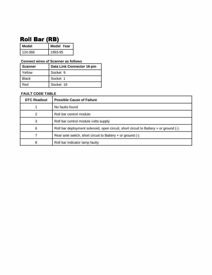
���� %!# �%����� %!# �%����� %!# �%����� %!# �%�Model Model Year
124.066 1993-95
Connect wires of Scanner as f ollowsScanner Data Link Connector 16-pin
Yellow Socket 9
Black Socket 1
Red Socket 16
FAULT CODE TABLE
DTC Readout Possible Cause of Failure
1 No faults found
2 Roll bar control module
3 Roll bar control module volts supply
6 Roll bar deployment solenoid, open circuit, short circuit to Battery + or ground (-).
7 Rear axle switch, short circuit to Battery + or ground (-).
8 Roll bar indicator lamp faulty
����1 ANALOG CODES CS1000 Code Scanner OB15-11
68
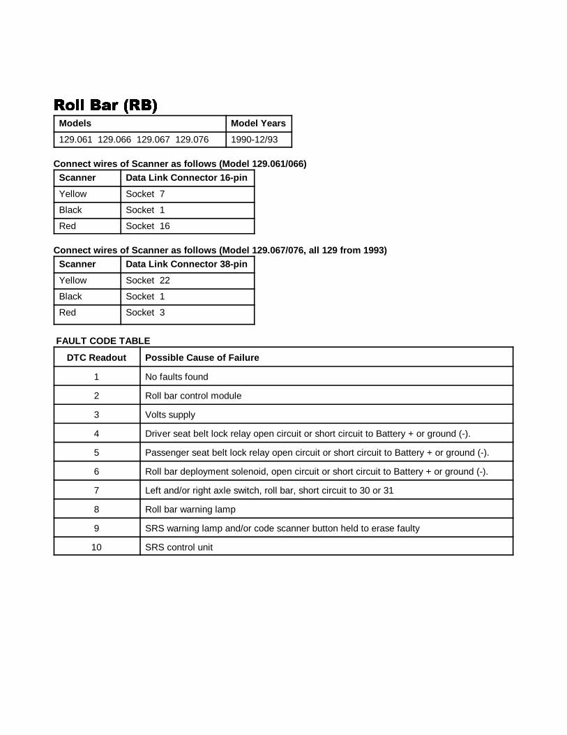
���� %!# �%����� %!# �%����� %!# �%����� %!# �%�Models Model Years
129.061 129.066 129.067 129.076 1990-12/93
Connect wires of Scanner as f ollows (Model 129.061/066)Scanner Data Link Connector 16-pin
Yellow Socket 7
Black Socket 1
Red Socket 16
Connect wires of Scanner as f ollows (Model 129.067/076, all 129 from 1993)Scanner Data Link Connector 38-pin
Yellow Socket 22
Black Socket 1
Red Socket 3
FAULT CODE TABLE
DTC Readout Possible Cause of Failure
1 No faults found
2 Roll bar control module
3 Volts supply
4 Driver seat belt lock relay open circuit or short circuit to Battery + or ground (-).
5 Passenger seat belt lock relay open circuit or short circuit to Battery + or ground (-).
6 Roll bar deployment solenoid, open circuit or short circuit to Battery + or ground (-).
7 Left and/or right axle switch, roll bar, short circuit to 30 or 31
8 Roll bar warning lamp
9 SRS warning lamp and/or code scanner button held to erase faulty
10 SRS control unit
����1 ANALOG CODES CS1000 Code Scanner OB15-11
69
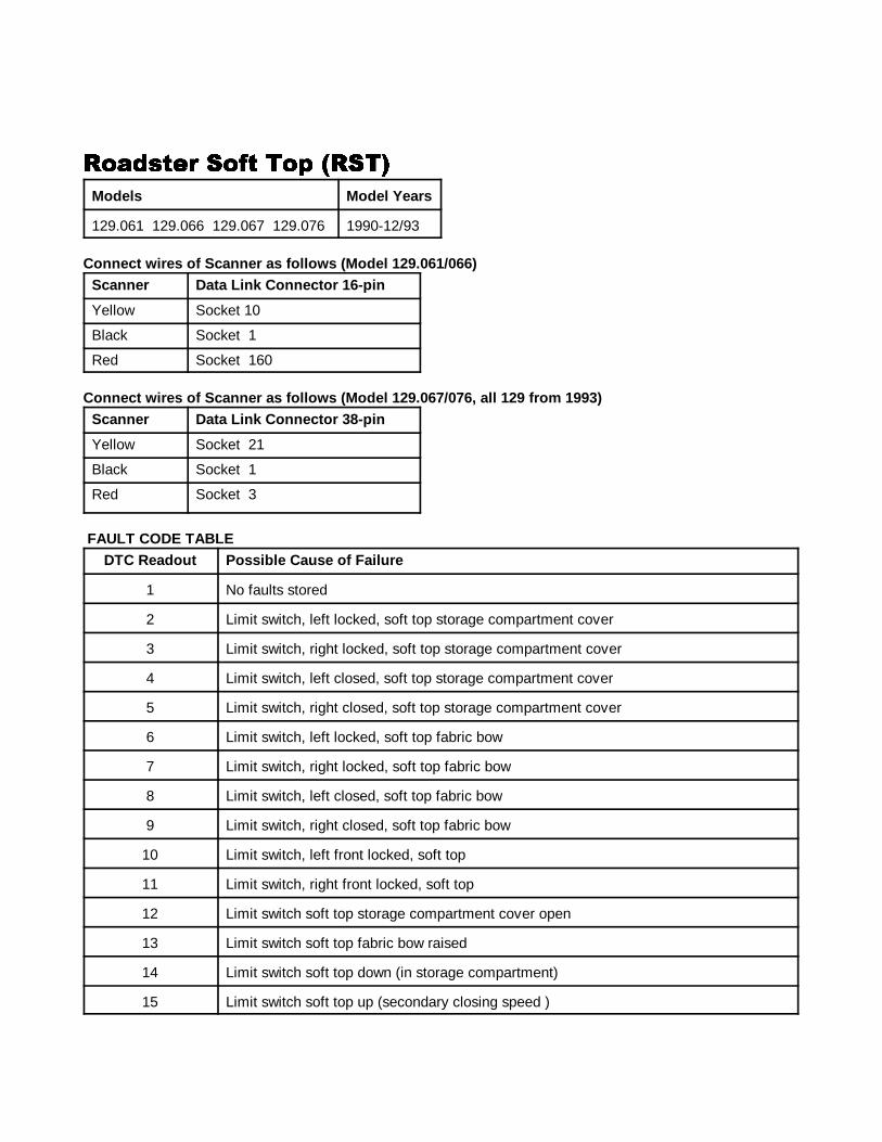
��!&���# ��/� ��" ������!&���# ��/� ��" ������!&���# ��/� ��" ������!&���# ��/� ��" ����
Models Model Years
129.061 129.066 129.067 129.076 1990-12/93
Connect wires of Scanner as f ollows (Model 129.061/066)Scanner Data Link Connector 16-pin
Yellow Socket 10
Black Socket 1
Red Socket 160
Connect wires of Scanner as f ollows (Model 129.067/076, all 129 from 1993)Scanner Data Link Connector 38-pin
Yellow Socket 21
Black Socket 1
Red Socket 3
FAULT CODE TABLEDTC Readout Possible Cause of Failure
1 No faults stored
2 Limit switch, left locked, soft top storage compartment cover
3 Limit switch, right locked, soft top storage compartment cover
4 Limit switch, left closed, soft top storage compartment cover
5 Limit switch, right closed, soft top storage compartment cover
6 Limit switch, left locked, soft top fabric bow
7 Limit switch, right locked, soft top fabric bow
8 Limit switch, left closed, soft top fabric bow
9 Limit switch, right closed, soft top fabric bow
10 Limit switch, left front locked, soft top
11 Limit switch, right front locked, soft top
12 Limit switch soft top storage compartment cover open
13 Limit switch soft top fabric bow raised
14 Limit switch soft top down (in storage compartment)
15 Limit switch soft top up (secondary closing speed )
����1 ANALOG CODES CS1000 Code Scanner OB15-11
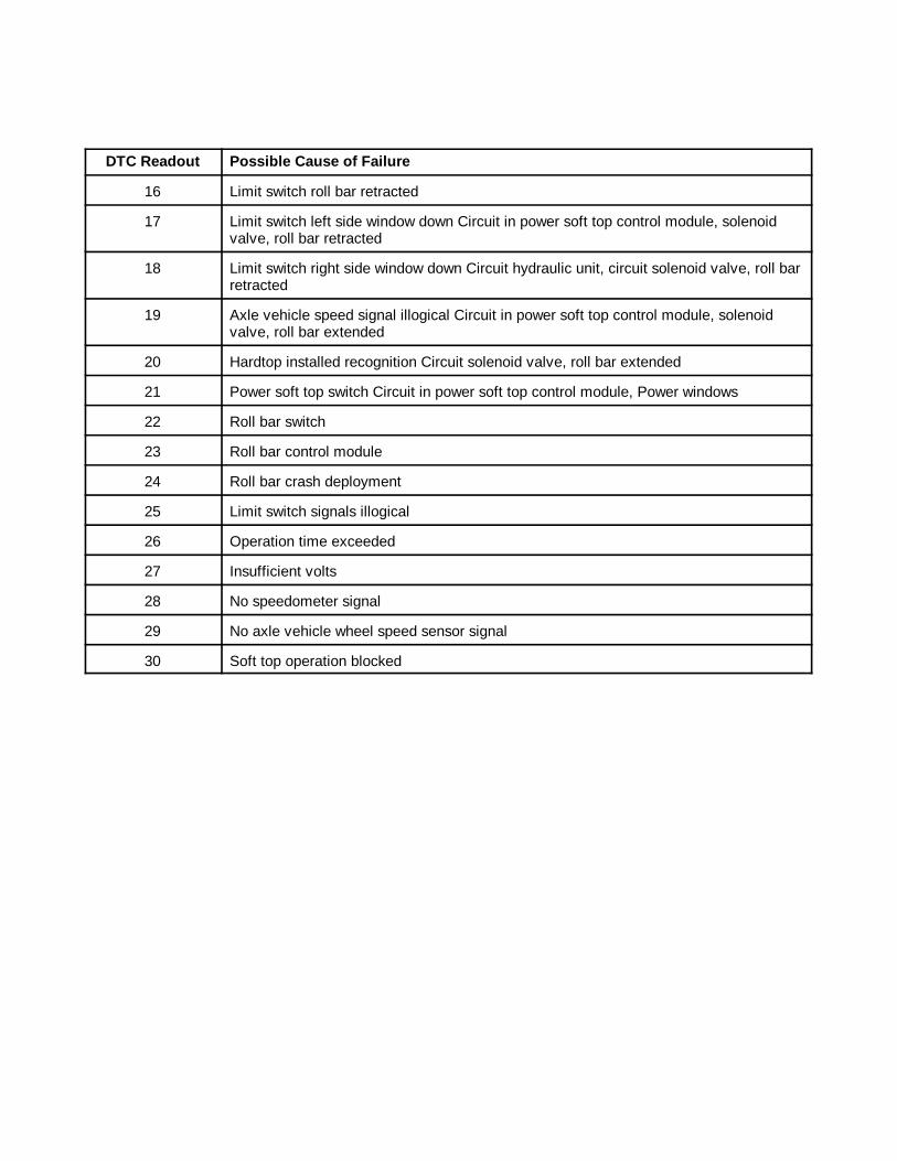
DTC Readout Possible Cause of Failure
70
16 Limit switch roll bar retracted
17 Limit switch left side window down Circuit in power soft top control module, solenoidvalve, roll bar retracted
18 Limit switch right side window down Circuit hydraulic unit, circuit solenoid valve, roll barretracted
19 Axle vehicle speed signal illogical Circuit in power soft top control module, solenoidvalve, roll bar extended
20 Hardtop installed recognition Circuit solenoid valve, roll bar extended
21 Power soft top switch Circuit in power soft top control module, Power windows
22 Roll bar switch
23 Roll bar control module
24 Roll bar crash deployment
25 Limit switch signals illogical
26 Operation time exceeded
27 Insufficient volts
28 No speedometer signal
29 No axle vehicle wheel speed sensor signal
30 Soft top operation blocked
����1 ANALOG CODES CS1000 Code Scanner OB15-11
71
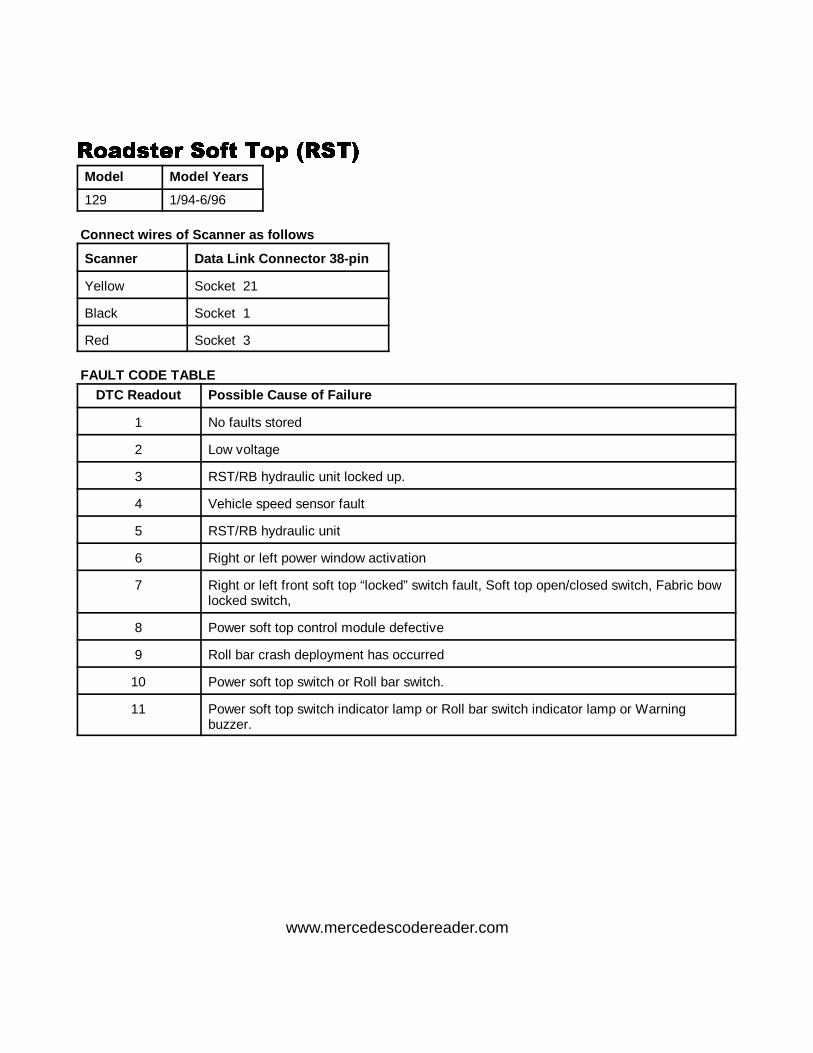
��!&���# ��/� ��" ������!&���# ��/� ��" ������!&���# ��/� ��" ������!&���# ��/� ��" ����Model Model Years
129 1/94-6/96
Connect wires of Scanner as f ollows
Scanner Data Link Connector 38-pin
Yellow Socket 21
Black Socket 1
Red Socket 3
FAULT CODE TABLEDTC Readout Possible Cause of Failure
1 No faults stored
2 Low voltage
3 RST/RB hydraulic unit locked up.
4 Vehicle speed sensor fault
5 RST/RB hydraulic unit
6 Right or left power window activation
7 Right or left front soft top “locked” switch fault, Soft top open/closed switch, Fabric bowlocked switch,
8 Power soft top control module defective
9 Roll bar crash deployment has occurred
10 Power soft top switch or Roll bar switch.
11 Power soft top switch indicator lamp or Roll bar switch indicator lamp or Warningbuzzer.
www.mercedescodereader.com
����1 ANALOG CODES CS1000 Code Scanner OB15-11
72
��/#!#�& ������ ����#�� /�# ����#!� ���.��' �������/#!#�& ������ ����#�� /�# ����#!� ���.��' �������/#!#�& ������ ����#�� /�# ����#!� ���.��' �������/#!#�& ������ ����#�� /�# ����#!� ���.��' �����Models Model Years
129.061 129.066 129.067 129.076 1990-1993
Connect wires of Scanner as f ollowsScanner Data Link Connector 16-pin
Yellow Socket 12
Black Socket 1
Red Socket 16
Scanner Data Link Connector 38-pin
Yellow Socket 31
Black Socket 1
Red Socket 3
FAULT CODE TABLEDTC Readout Possible Cause of Failure
1 No fault found
2 Infrared remote control module
3 Supply pump, central locking system short to ground
4 Infrared remote control receiver, Left front door/Right front door/Trunk lid Red indicatorlamps, short to ground
5 Infrared remote control receiver, Left front door/Right front door/Trunk lid Greenindicator lamps, short to ground
6 Supply pump, central locking system, short to circuit 30
7 Infrared remote control receiver, Left front door/Right front door/Trunk lid Red indicatorlamps, short to circuit 30 or open circuit
8 Infrared remote control receiver, Left front door/Right front door/Trunk lid Greenindicator lamps, in receiver have short to short to circuit 30 or open circuit
9 Driver door switch group wiring, short to circuit 30 ATA/convenience microswitch wiringshort to circuit 30 ATA/convenience microswitch wiring short to circuit 30
10 Ignition/starter switch-position recognition switch, open circuit
11 Ignition/starter switch-position recognition switch, open circuit 31
12 Left front door actuator, open circuit
13 Right door actuator, open circuit
14 Trunk lid lock actuator, open circuit
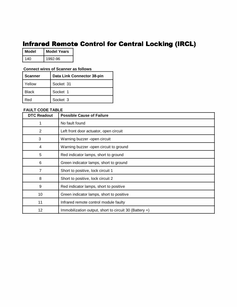
����1 ANALOG CODES CS1000 Code Scanner OB15-11
73
��/#!#�& ������ ����#�� /�# ����#!� ���.��' �������/#!#�& ������ ����#�� /�# ����#!� ���.��' �������/#!#�& ������ ����#�� /�# ����#!� ���.��' �������/#!#�& ������ ����#�� /�# ����#!� ���.��' �����Model Model Years
140 1992-96
Connect wires of Scanner as f ollows
Scanner Data Link Connector 38-pin
Yellow Socket 31
Black Socket 1
Red Socket 3
FAULT CODE TABLEDTC Readout Possible Cause of Failure
1 No fault found
2 Left front door actuator, open circuit
3 Warning buzzer -open circuit
4 Warning buzzer -open circuit to ground
5 Red indicator lamps, short to ground
6 Green indicator lamps, short to ground
7 Short to positive, lock circuit 1
8 Short to positive, lock circuit 2
9 Red indicator lamps, short to positive
10 Green indicator lamps, short to positive
11 Infrared remote control module faulty
12 Immobilization output, short to circuit 30 (Battery +)
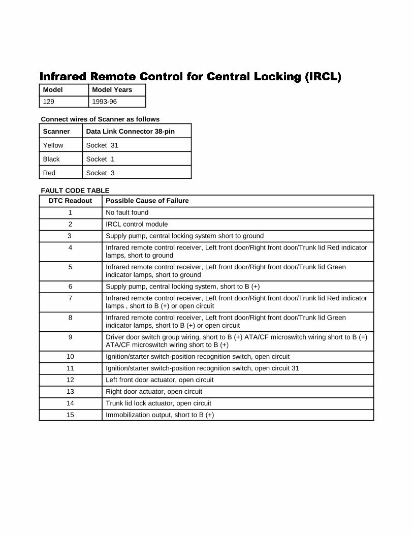
����1 ANALOG CODES CS1000 Code Scanner OB15-11
74
��/#!#�& ������ ����#�� /�# ����#!� ���.��' �������/#!#�& ������ ����#�� /�# ����#!� ���.��' �������/#!#�& ������ ����#�� /�# ����#!� ���.��' �������/#!#�& ������ ����#�� /�# ����#!� ���.��' �����Model Model Years
129 1993-96
Connect wires of Scanner as f ollows
Scanner Data Link Connector 38-pin
Yellow Socket 31
Black Socket 1
Red Socket 3
FAULT CODE TABLEDTC Readout Possible Cause of Failure
1 No fault found
2 IRCL control module
3 Supply pump, central locking system short to ground
4 Infrared remote control receiver, Left front door/Right front door/Trunk lid Red indicatorlamps, short to ground
5 Infrared remote control receiver, Left front door/Right front door/Trunk lid Greenindicator lamps, short to ground
6 Supply pump, central locking system, short to B (+)
7 Infrared remote control receiver, Left front door/Right front door/Trunk lid Red indicatorlamps , short to B (+) or open circuit
8 Infrared remote control receiver, Left front door/Right front door/Trunk lid Greenindicator lamps, short to B (+) or open circuit
9 Driver door switch group wiring, short to B (+) ATA/CF microswitch wiring short to B (+) ATA/CF microswitch wiring short to B (+)
10 Ignition/starter switch-position recognition switch, open circuit
11 Ignition/starter switch-position recognition switch, open circuit 31
12 Left front door actuator, open circuit
13 Right door actuator, open circuit
14 Trunk lid lock actuator, open circuit
15 Immobilization output, short to B (+)
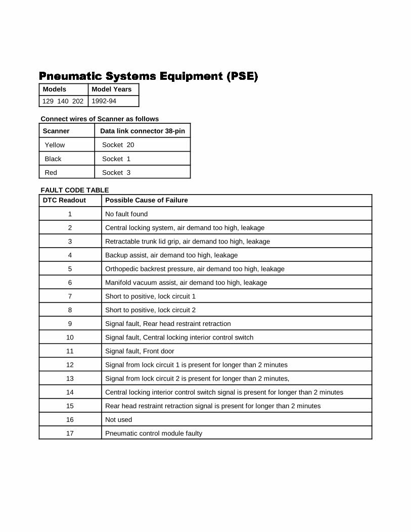
����1 ANALOG CODES CS1000 Code Scanner OB15-11
75
�����!��� ������� � ��"���� ���������!��� ������� � ��"���� ���������!��� ������� � ��"���� ���������!��� ������� � ��"���� ����Models Model Years
129 140 1992-94
Connect wires of Scanner as f ollows
Scanner Data link connector 38-pin
Yellow Socket 20
Black Socket 1
Red Socket 3
FAULT CODE TABLEDTC Readout Possible Cause of Failure
1 No fault found
2 Central locking system, air demand too high, leakage
3 Retractable trunk lid grip, air demand too high, leakage
4 Backup assist, air demand too high, leakage
5 Orthopedic backrest pressure, air demand too high, leakage
6 Manifold vacuum assist, air demand too high, leakage
7 Short to positive, lock circuit 1
8 Short to positive, lock circuit 2
9 Signal fault, Rear head restraint retraction
10 Signal fault, Central locking interior control switch
11 Signal fault, Front door
12 Signal from lock circuit 1 is present for longer than 2 minutes
13 Signal from lock circuit 2 is present for longer than 2 minutes,
14 Central locking interior control switch signal is present for longer than 2 minutes
15 Rear head restraint retraction signal is present for longer than 2 minutes
16 Not used
17 Pneumatic control module faulty
129 140 202
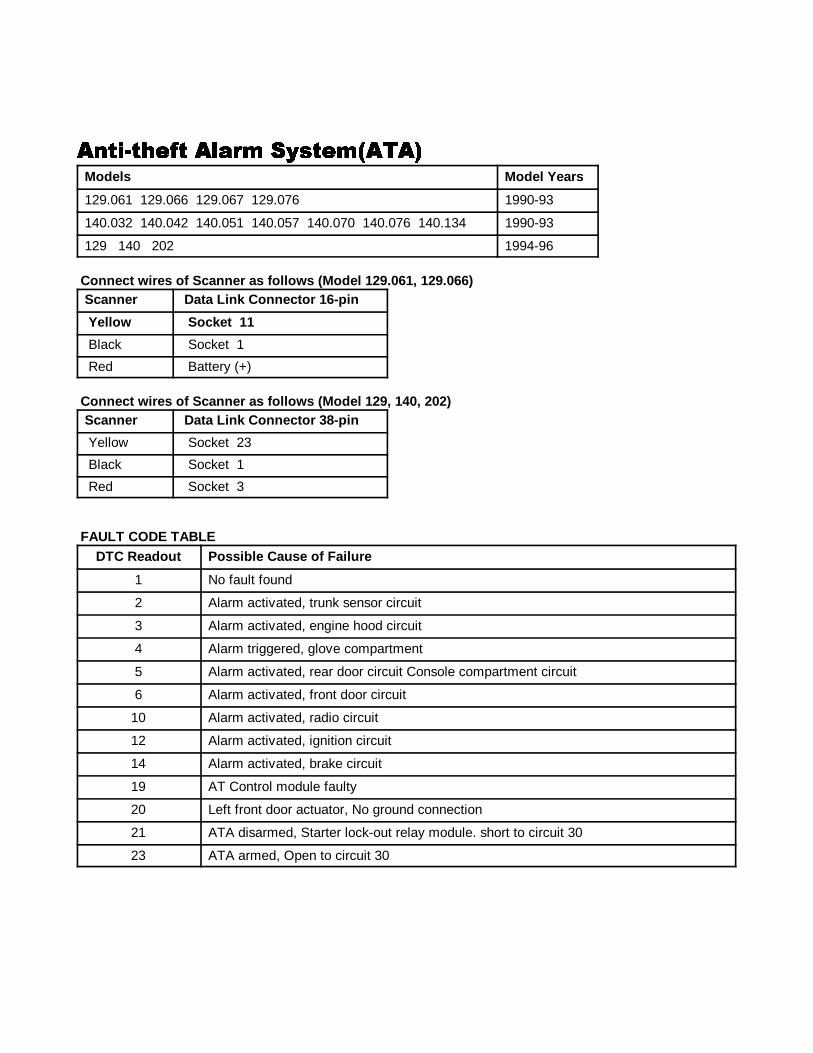
����1 ANALOG CODES CS1000 Code Scanner OB15-11
76
����$�+�/� ��!#� ������ ��������$�+�/� ��!#� ������ ��������$�+�/� ��!#� ������ ��������$�+�/� ��!#� ������ ����Models Model Years
129.061 129.066 129.067 129.076 1990-93
140.032 140.042 140.051 140.057 140.070 140.076 140.134 1990-93
129 140 202 1994-96
Connect wires of Scanner as f ollows (Model 129.061, 129.066)Scanner Data Link Connector 16-pin
Yellow So cket 11
Black Socket 1
Red Battery (+)
Connect wires of Scanner as f ollows (Model 129, 140, 202)Scanner Data Link Connector 38-pin
Yellow Socket 23
Black Socket 1
Red Socket 3
FAULT CODE TABLEDTC Readout Possible Cause of Failure
1 No fault found
2 Alarm activated, trunk sensor circuit
3 Alarm activated, engine hood circuit
4 Alarm triggered, glove compartment
5 Alarm activated, rear door circuit Console compartment circuit
6 Alarm activated, front door circuit
10 Alarm activated, radio circuit
12 Alarm activated, ignition circuit
14 Alarm activated, brake circuit
19 AT Control module faulty
20 Left front door actuator, No ground connection
21 ATA disarmed, Starter lock-out relay module. short to circuit 30
23 ATA armed, Open to circuit 30
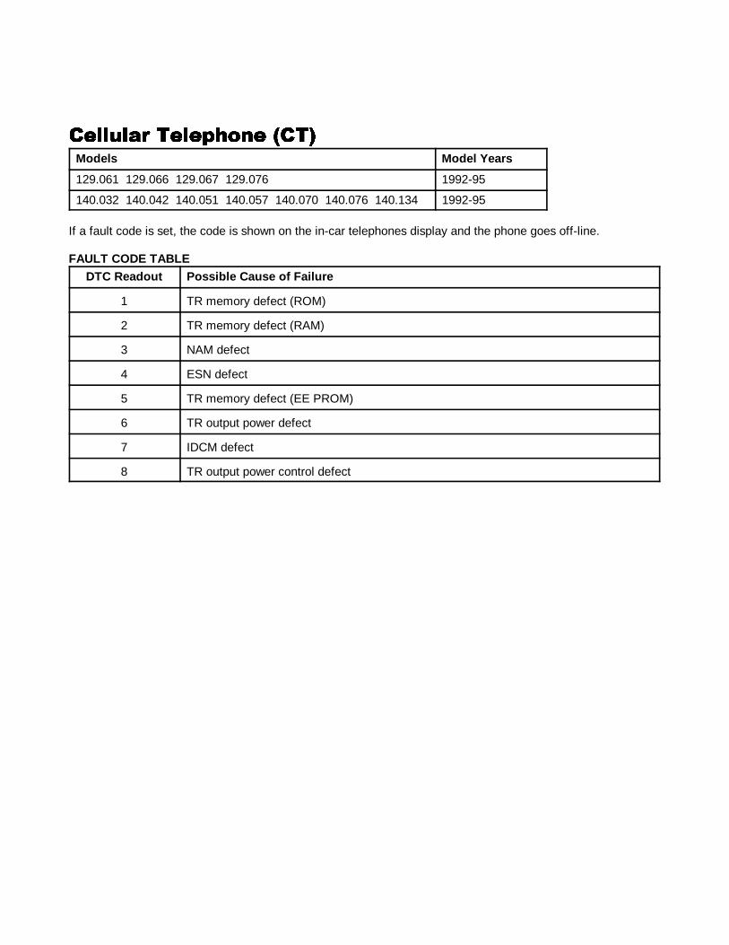
����1 ANALOG CODES CS1000 Code Scanner OB15-11
77
������!# ����"+��� ���������!# ����"+��� ���������!# ����"+��� ���������!# ����"+��� ���Models Model Years
129.061 129.066 129.067 129.076 1992-95
140.032 140.042 140.051 140.057 140.070 140.076 140.134 1992-95
If a fault code is set, the code is shown on the in-car telephones display and the phone goes off-line.
FAULT CODE TABLEDTC Readout Possible Cause of Failure
1 TR memory defect (ROM)
2 TR memory defect (RAM)
3 NAM defect
4 ESN defect
5 TR memory defect (EE PROM)
6 TR output power defect
7 IDCM defect
8 TR output power control defect
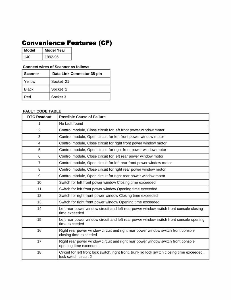
����1 ANALOG CODES CS1000 Code Scanner OB15-11
78
���,������� ��!��#�� ������,������� ��!��#�� ������,������� ��!��#�� ������,������� ��!��#�� ���Model Model Year
140 1992-96
Connect wires of Scanner as f ollows
Scanner Data Link Connector 38-pin
Yellow Socket 21
Black Socket 1
Red Socket 3
FAULT CODE TABLEDTC Readout Possible Cause of Failure
1 No fault found
2 Control module, Close circuit for left front power window motor
3 Control module, Open circuit for left front power window motor
4 Control module, Close circuit for right front power window motor
5 Control module, Open circuit for right front power window motor
6 Control module, Close circuit for left rear power window motor
7 Control module, Open circuit for left rear front power window motor
8 Control module, Close circuit for right rear power window motor
9 Control module, Open circuit for right rear power window motor
10 Switch for left front power window Closing time exceeded
11 Switch for left front power window Opening time exceeded
12 Switch for right front power window Closing time exceeded
13 Switch for right front power window Opening time exceeded
14 Left rear power window circuit and left rear power window switch front console closingtime exceeded
15 Left rear power window circuit and left rear power window switch front console openingtime exceeded
16 Right rear power window circuit and right rear power window switch front consoleclosing time exceeded
17 Right rear power window circuit and right rear power window switch front consoleopening time exceeded
18 Circuit for left front lock switch, right front, trunk lid lock switch closing time exceeded,lock switch circuit 2
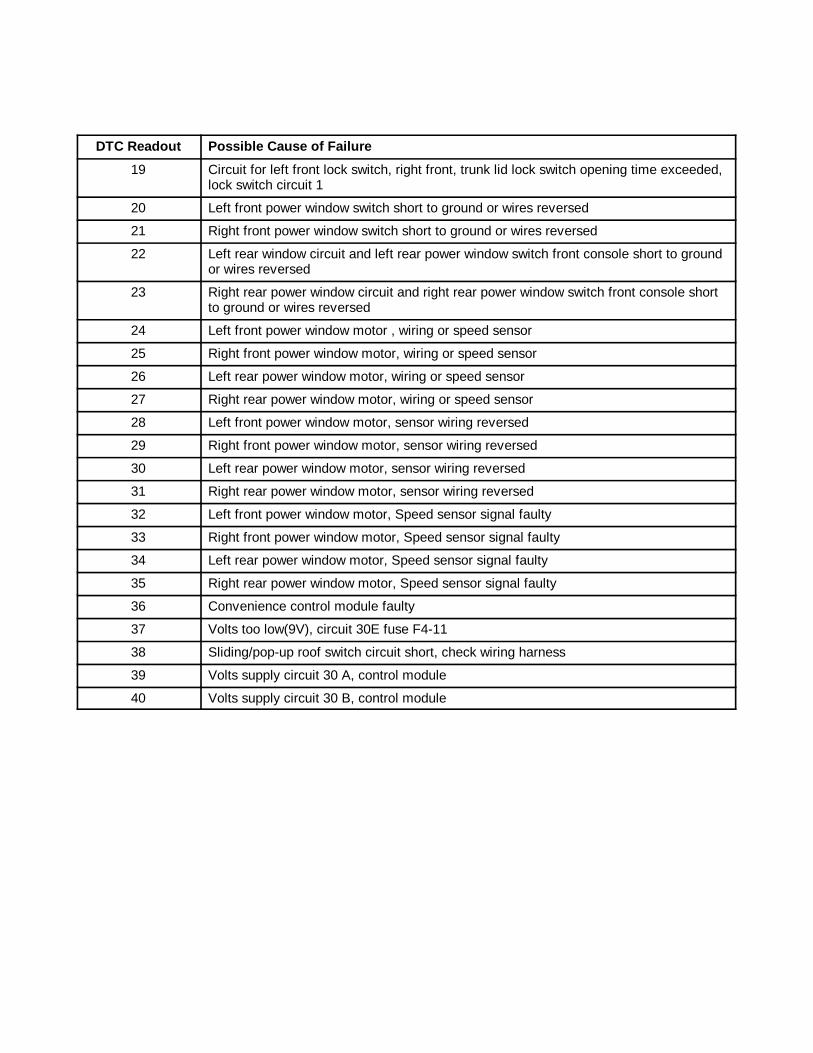
����1 ANALOG CODES CS1000 Code Scanner OB15-11
DTC Readout Possible Cause of Failure
79
19 Circuit for left front lock switch, right front, trunk lid lock switch opening time exceeded,lock switch circuit 1
20 Left front power window switch short to ground or wires reversed
21 Right front power window switch short to ground or wires reversed
22 Left rear window circuit and left rear power window switch front console short to groundor wires reversed
23 Right rear power window circuit and right rear power window switch front console shortto ground or wires reversed
24 Left front power window motor , wiring or speed sensor
25 Right front power window motor, wiring or speed sensor
26 Left rear power window motor, wiring or speed sensor
27 Right rear power window motor, wiring or speed sensor
28 Left front power window motor, sensor wiring reversed
29 Right front power window motor, sensor wiring reversed
30 Left rear power window motor, sensor wiring reversed
31 Right rear power window motor, sensor wiring reversed
32 Left front power window motor, Speed sensor signal faulty
33 Right front power window motor, Speed sensor signal faulty
34 Left rear power window motor, Speed sensor signal faulty
35 Right rear power window motor, Speed sensor signal faulty
36 Convenience control module faulty
37 Volts too low(9V), circuit 30E fuse F4-11
38 Sliding/pop-up roof switch circuit short, check wiring harness
39 Volts supply circuit 30 A, control module
40 Volts supply circuit 30 B, control module
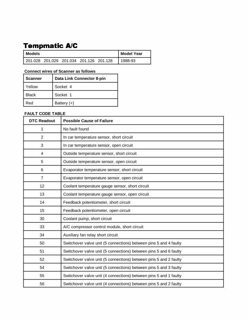
����1 ANALOG CODES CS1000 Code Scanner OB15-11
80
���"�!��� �)����"�!��� �)����"�!��� �)����"�!��� �)�Models Model Year
201.028 201.029 201.034 201.126 201.128 1988-93
Connect wires of Scanner as f ollows
Scanner Data Link Connector 8-pin
Yellow Socket 4
Black Socket 1
Red Battery (+)
FAULT CODE TABLE
DTC Readout Possible Cause of Failure
1 No fault found
2 In car temperature sensor, short circuit
3 In car temperature sensor, open circuit
4 Outside temperature sensor, short circuit
5 Outside temperature sensor, open circuit
6 Evaporator temperature sensor, short circuit
7 Evaporator temperature sensor, open circuit
12 Coolant temperature gauge sensor, short circuit
13 Coolant temperature gauge sensor, open circuit
14 Feedback potentiometer, short circuit
15 Feedback potentiometer, open circuit
30 Coolant pump, short circuit
33 A/C compressor control module, short circuit
34 Auxiliary fan relay short circuit
50 Switchover valve unit (5 connections) between pins 5 and 4 faulty
51 Switchover valve unit (5 connections) between pins 5 and 6 faulty
52 Switchover valve unit (5 connections) between pins 5 and 2 faulty
54 Switchover valve unit (5 connections) between pins 5 and 3 faulty
55 Switchover valve unit (4 connections) between pins 5 and 1 faulty
56 Switchover valve unit (4 connections) between pins 5 and 2 faulty
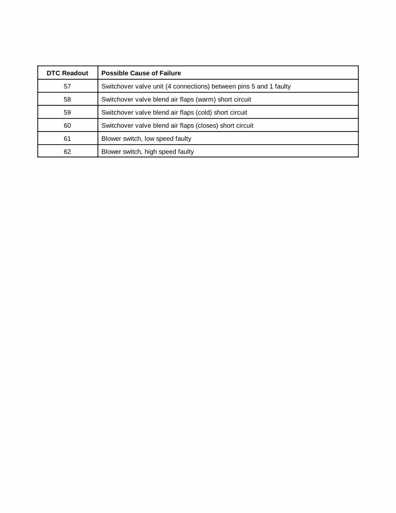
����1 ANALOG CODES CS1000 Code Scanner OB15-11
DTC Readout Possible Cause of Failure
81
57 Switchover valve unit (4 connections) between pins 5 and 1 faulty
58 Switchover valve blend air flaps (warm) short circuit
59 Switchover valve blend air flaps (cold) short circuit
60 Switchover valve blend air flaps (closes) short circuit
61 Blower switch, low speed faulty
62 Blower switch, high speed faulty
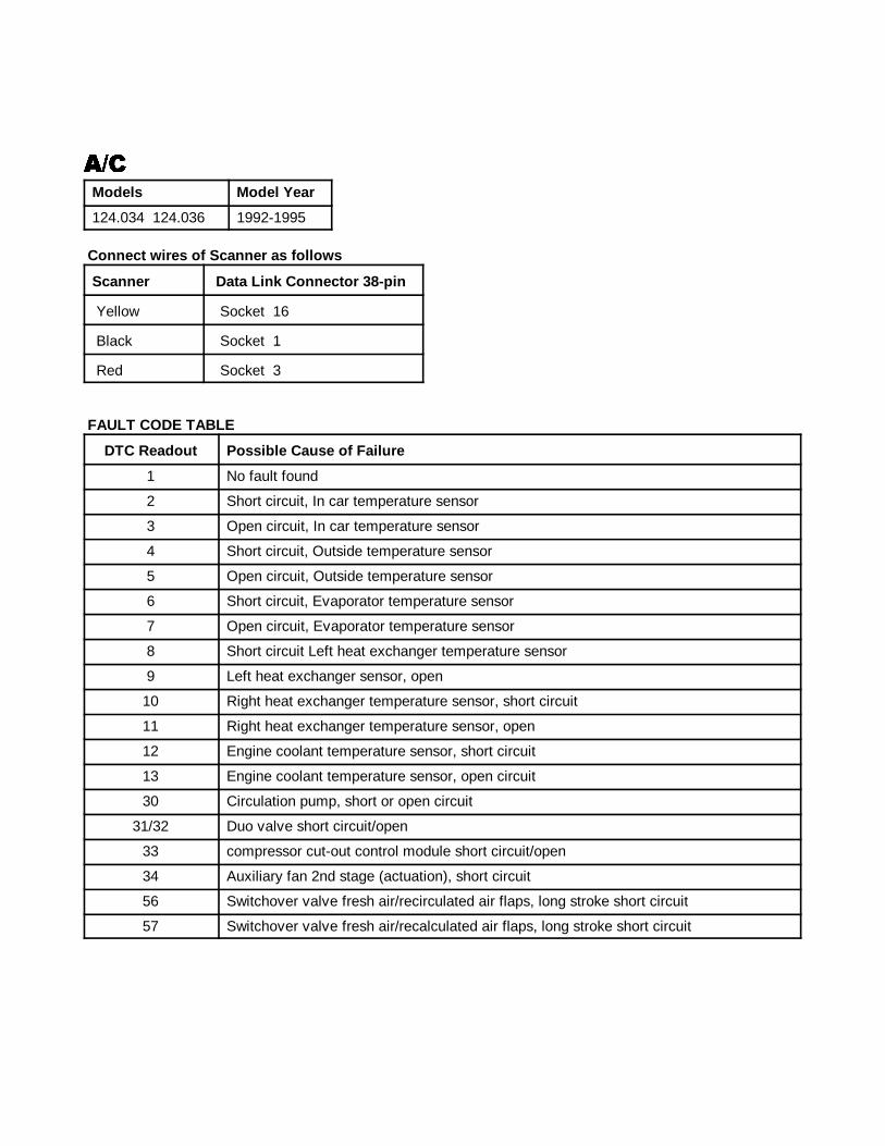
����1 ANALOG CODES CS1000 Code Scanner OB15-11
82
�)��)��)��)�Models Model Year
124.034 124.036 1992-1995
Connect wires of Scanner as f ollows
Scanner Data Link Connector 38-pin
Yellow Socket 16
Black Socket 1
Red Socket 3
FAULT CODE TABLE
DTC Readout Possible Cause of Failure
1 No fault found
2 Short circuit, In car temperature sensor
3 Open circuit, In car temperature sensor
4 Short circuit, Outside temperature sensor
5 Open circuit, Outside temperature sensor
6 Short circuit, Evaporator temperature sensor
7 Open circuit, Evaporator temperature sensor
8 Short circuit Left heat exchanger temperature sensor
9 Left heat exchanger sensor, open
10 Right heat exchanger temperature sensor, short circuit
11 Right heat exchanger temperature sensor, open
12 Engine coolant temperature sensor, short circuit
13 Engine coolant temperature sensor, open circuit
30 Circulation pump, short or open circuit
31/32 Duo valve short circuit/open
33 compressor cut-out control module short circuit/open
34 Auxiliary fan 2nd stage (actuation), short circuit
56 Switchover valve fresh air/recirculated air flaps, long stroke short circuit
57 Switchover valve fresh air/recalculated air flaps, long stroke short circuit
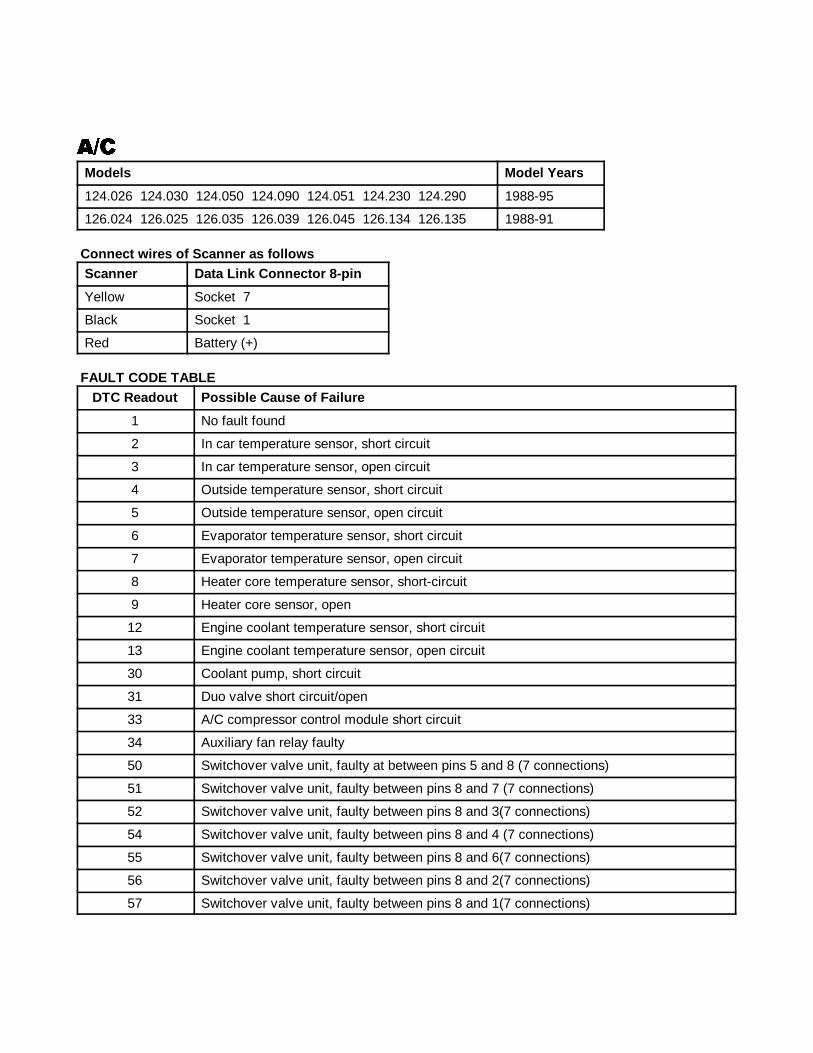
�)� ���� ��2������ ��������)� ���� ��2������ ��������)� ���� ��2������ ��������)� ���� ��2������ �������
83
�)��)��)��)�
Models Model Years
124.026 124.030 124.050 124.090 124.051 124.230 124.290 1988-95
126.024 126.025 126.035 126.039 126.045 126.134 126.135 1988-91
Connect wires of Scanner as f ollowsScanner Data Link Connector 8-pin
Yellow Socket 7
Black Socket 1
Red Battery (+)
FAULT CODE TABLEDTC Readout Possible Cause of Failure
1 No fault found
2 In car temperature sensor, short circuit
3 In car temperature sensor, open circuit
4 Outside temperature sensor, short circuit
5 Outside temperature sensor, open circuit
6 Evaporator temperature sensor, short circuit
7 Evaporator temperature sensor, open circuit
8 Heater core temperature sensor, short-circuit
9 Heater core sensor, open
12 Engine coolant temperature sensor, short circuit
13 Engine coolant temperature sensor, open circuit
30 Coolant pump, short circuit
31 Duo valve short circuit/open
33 A/C compressor control module short circuit
34 Auxiliary fan relay faulty
50 Switchover valve unit, faulty at between pins 5 and 8 (7 connections)
51 Switchover valve unit, faulty between pins 8 and 7 (7 connections)
52 Switchover valve unit, faulty between pins 8 and 3(7 connections)
54 Switchover valve unit, faulty between pins 8 and 4 (7 connections)
55 Switchover valve unit, faulty between pins 8 and 6(7 connections)
56 Switchover valve unit, faulty between pins 8 and 2(7 connections)
57 Switchover valve unit, faulty between pins 8 and 1(7 connections)
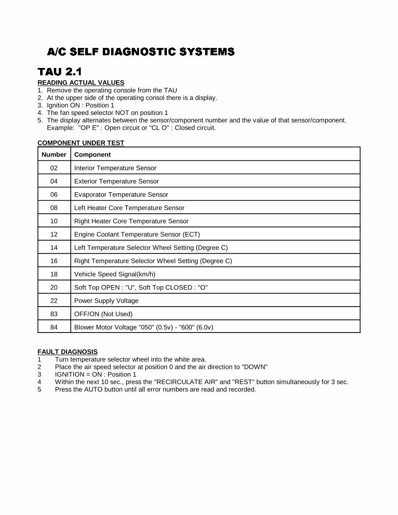
�)� ���� ��2������ ��������)� ���� ��2������ ��������)� ���� ��2������ ��������)� ���� ��2������ �������
84
��3 456��3 456��3 456��3 456READING ACTUAL VALUES1. Remove the operating console from the TAU2. At the upper side of the operating consol there is a display.3. Ignition ON : Position 14. The fan speed selector NOT on position 15. The display alternates between the sensor/component number and the value of that sensor/component.
Example: "OP E" : Open circuit or "CL O" : Closed circuit.
COMPONENT UNDER TEST
Number Component
02 Interior Temperature Sensor
04 Exterior Temperature Sensor
06 Evaporator Temperature Sensor
08 Left Heater Core Temperature Sensor
10 Right Heater Core Temperature Sensor
12 Engine Coolant Temperature Sensor (ECT)
14 Left Temperature Selector Wheel Setting (Degree C)
16 Right Temperature Selector Wheel Setting (Degree C)
18 Vehicle Speed Signal(km/h)
20 Soft Top OPEN : "U", Soft Top CLOSED : "O"
22 Power Supply Voltage
83 OFF/ON (Not Used)
84 Blower Motor Voltage "050" (0.5v) - "600" (6.0v)
FAULT DIAGNOSIS1 Turn temperature selector wheel into the white area.2 Place the air speed selector at position 0 and the air direction to "DOWN"3 IGNITION = ON : Position 14 Within the next 10 sec., press the "RECIRCULATE AIR" and "REST" button simultaneously for 3 sec.5 Press the AUTO button until all error numbers are read and recorded.
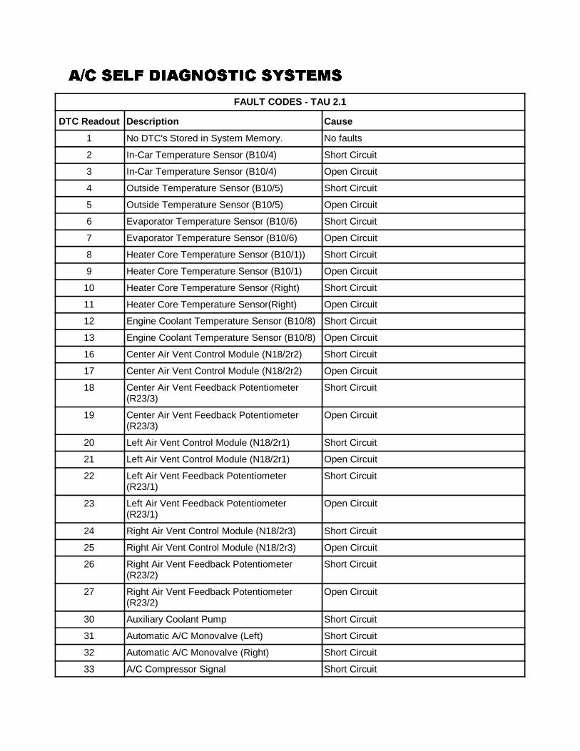
�)� ���� ��2������ ��������)� ���� ��2������ ��������)� ���� ��2������ ��������)� ���� ��2������ �������
85
FAULT CODES - TAU 2.1
DTC Readout Description Cause
1 No DTC's Stored in System Memory. No faults
2 In-Car Temperature Sensor (B10/4) Short Circuit
3 In-Car Temperature Sensor (B10/4) Open Circuit
4 Outside Temperature Sensor (B10/5) Short Circuit
5 Outside Temperature Sensor (B10/5) Open Circuit
6 Evaporator Temperature Sensor (B10/6) Short Circuit
7 Evaporator Temperature Sensor (B10/6) Open Circuit
8 Heater Core Temperature Sensor (B10/1)) Short Circuit
9 Heater Core Temperature Sensor (B10/1) Open Circuit
10 Heater Core Temperature Sensor (Right) Short Circuit
11 Heater Core Temperature Sensor(Right) Open Circuit
12 Engine Coolant Temperature Sensor (B10/8) Short Circuit
13 Engine Coolant Temperature Sensor (B10/8) Open Circuit
16 Center Air Vent Control Module (N18/2r2) Short Circuit
17 Center Air Vent Control Module (N18/2r2) Open Circuit
18 Center Air Vent Feedback Potentiometer(R23/3)
Short Circuit
19 Center Air Vent Feedback Potentiometer(R23/3)
Open Circuit
20 Left Air Vent Control Module (N18/2r1) Short Circuit
21 Left Air Vent Control Module (N18/2r1) Open Circuit
22 Left Air Vent Feedback Potentiometer(R23/1)
Short Circuit
23 Left Air Vent Feedback Potentiometer(R23/1)
Open Circuit
24 Right Air Vent Control Module (N18/2r3) Short Circuit
25 Right Air Vent Control Module (N18/2r3) Open Circuit
26 Right Air Vent Feedback Potentiometer(R23/2)
Short Circuit
27 Right Air Vent Feedback Potentiometer(R23/2)
Open Circuit
30 Auxiliary Coolant Pump Short Circuit
31 Automatic A/C Monovalve (Left) Short Circuit
32 Automatic A/C Monovalve (Right) Short Circuit
33 A/C Compressor Signal Short Circuit
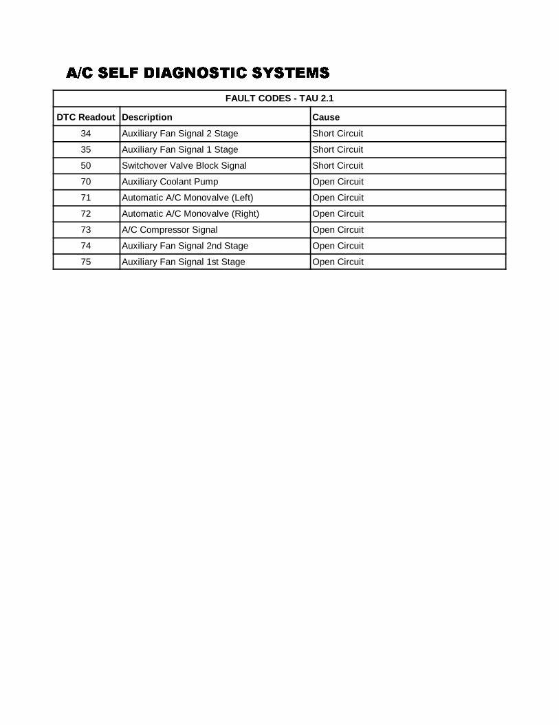
�)� ���� ��2������ ��������)� ���� ��2������ ��������)� ���� ��2������ ��������)� ���� ��2������ �������
FAULT CODES - TAU 2.1
DTC Readout Description Cause
86
34 Auxiliary Fan Signal 2 Stage Short Circuit
35 Auxiliary Fan Signal 1 Stage Short Circuit
50 Switchover Valve Block Signal Short Circuit
70 Auxiliary Coolant Pump Open Circuit
71 Automatic A/C Monovalve (Left) Open Circuit
72 Automatic A/C Monovalve (Right) Open Circuit
73 A/C Compressor Signal Open Circuit
74 Auxiliary Fan Signal 2nd Stage Open Circuit
75 Auxiliary Fan Signal 1st Stage Open Circuit
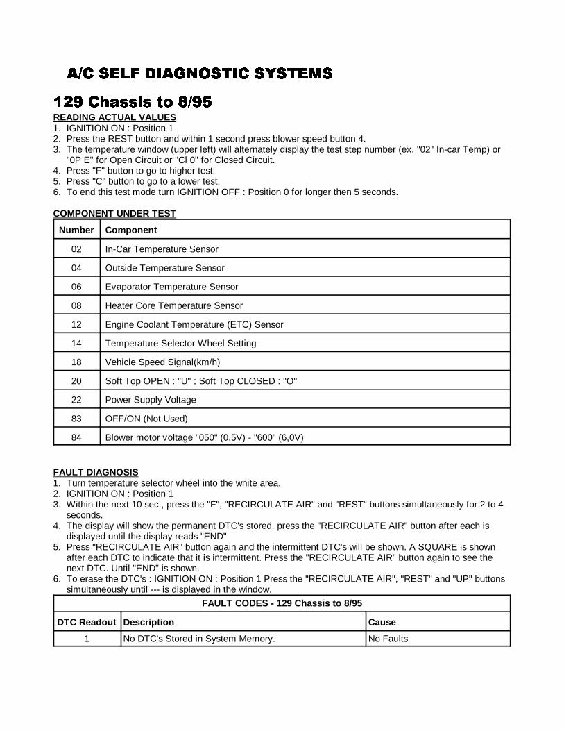
�)� ���� ��2������ ��������)� ���� ��2������ ��������)� ���� ��2������ ��������)� ���� ��2������ �������
87
647 �+!���� �� 8)79647 �+!���� �� 8)79647 �+!���� �� 8)79647 �+!���� �� 8)79READING ACTUAL VALUES1. IGNITION ON : Position 12. Press the REST button and within 1 second press blower speed button 4.3. The temperature window (upper left) will alternately display the test step number (ex. "02" In-car Temp) or
"0P E" for Open Circuit or "Cl 0" for Closed Circuit.4. Press "F" button to go to higher test.5. Press "C" button to go to a lower test.6. To end this test mode turn IGNITION OFF : Position 0 for longer then 5 seconds.
COMPONENT UNDER TEST
Number Component
02 In-Car Temperature Sensor
04 Outside Temperature Sensor
06 Evaporator Temperature Sensor
08 Heater Core Temperature Sensor
12 Engine Coolant Temperature (ETC) Sensor
14 Temperature Selector Wheel Setting
18 Vehicle Speed Signal(km/h)
20 Soft Top OPEN : "U" ; Soft Top CLOSED : "O"
22 Power Supply Voltage
83 OFF/ON (Not Used)
84 Blower motor voltage "050" (0,5V) - "600" (6,0V)
FAULT DIAGNOSIS1. Turn temperature selector wheel into the white area.2. IGNITION ON : Position 13. Within the next 10 sec., press the "F", "RECIRCULATE AIR" and "REST" buttons simultaneously for 2 to 4
seconds.4. The display will show the permanent DTC's stored. press the "RECIRCULATE AIR" button after each is
displayed until the display reads "END"5. Press "RECIRCULATE AIR" button again and the intermittent DTC's will be shown. A SQUARE is shown
after each DTC to indicate that it is intermittent. Press the "RECIRCULATE AIR" button again to see thenext DTC. Until "END" is shown.
6. To erase the DTC's : IGNITION ON : Position 1 Press the "RECIRCULATE AIR", "REST" and "UP" buttonssimultaneously until --- is displayed in the window.
FAULT CODES - 129 Chassis to 8/95
DTC Readout Description Cause
1 No DTC's Stored in System Memory. No Faults
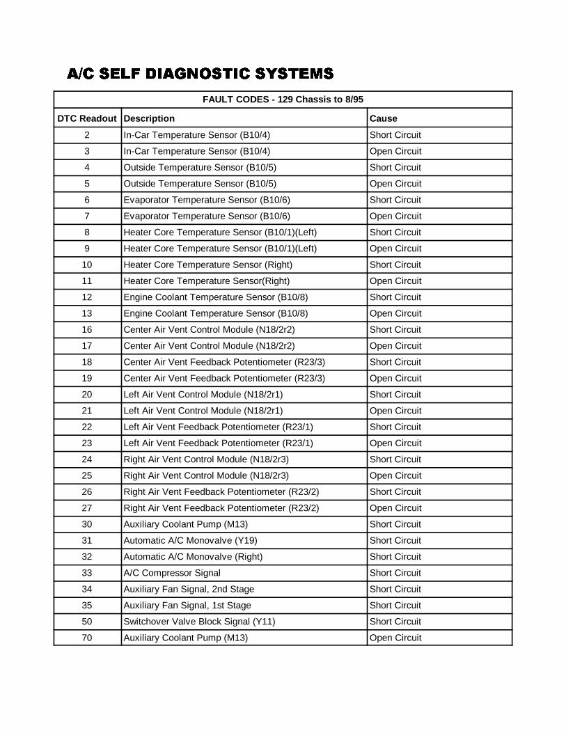
�)� ���� ��2������ ��������)� ���� ��2������ ��������)� ���� ��2������ ��������)� ���� ��2������ �������
FAULT CODES - 129 Chassis to 8/95
DTC Readout Description Cause
88
2 In-Car Temperature Sensor (B10/4) Short Circuit
3 In-Car Temperature Sensor (B10/4) Open Circuit
4 Outside Temperature Sensor (B10/5) Short Circuit
5 Outside Temperature Sensor (B10/5) Open Circuit
6 Evaporator Temperature Sensor (B10/6) Short Circuit
7 Evaporator Temperature Sensor (B10/6) Open Circuit
8 Heater Core Temperature Sensor (B10/1)(Left) Short Circuit
9 Heater Core Temperature Sensor (B10/1)(Left) Open Circuit
10 Heater Core Temperature Sensor (Right) Short Circuit
11 Heater Core Temperature Sensor(Right) Open Circuit
12 Engine Coolant Temperature Sensor (B10/8) Short Circuit
13 Engine Coolant Temperature Sensor (B10/8) Open Circuit
16 Center Air Vent Control Module (N18/2r2) Short Circuit
17 Center Air Vent Control Module (N18/2r2) Open Circuit
18 Center Air Vent Feedback Potentiometer (R23/3) Short Circuit
19 Center Air Vent Feedback Potentiometer (R23/3) Open Circuit
20 Left Air Vent Control Module (N18/2r1) Short Circuit
21 Left Air Vent Control Module (N18/2r1) Open Circuit
22 Left Air Vent Feedback Potentiometer (R23/1) Short Circuit
23 Left Air Vent Feedback Potentiometer (R23/1) Open Circuit
24 Right Air Vent Control Module (N18/2r3) Short Circuit
25 Right Air Vent Control Module (N18/2r3) Open Circuit
26 Right Air Vent Feedback Potentiometer (R23/2) Short Circuit
27 Right Air Vent Feedback Potentiometer (R23/2) Open Circuit
30 Auxiliary Coolant Pump (M13) Short Circuit
31 Automatic A/C Monovalve (Y19) Short Circuit
32 Automatic A/C Monovalve (Right) Short Circuit
33 A/C Compressor Signal Short Circuit
34 Auxiliary Fan Signal, 2nd Stage Short Circuit
35 Auxiliary Fan Signal, 1st Stage Short Circuit
50 Switchover Valve Block Signal (Y11) Short Circuit
70 Auxiliary Coolant Pump (M13) Open Circuit
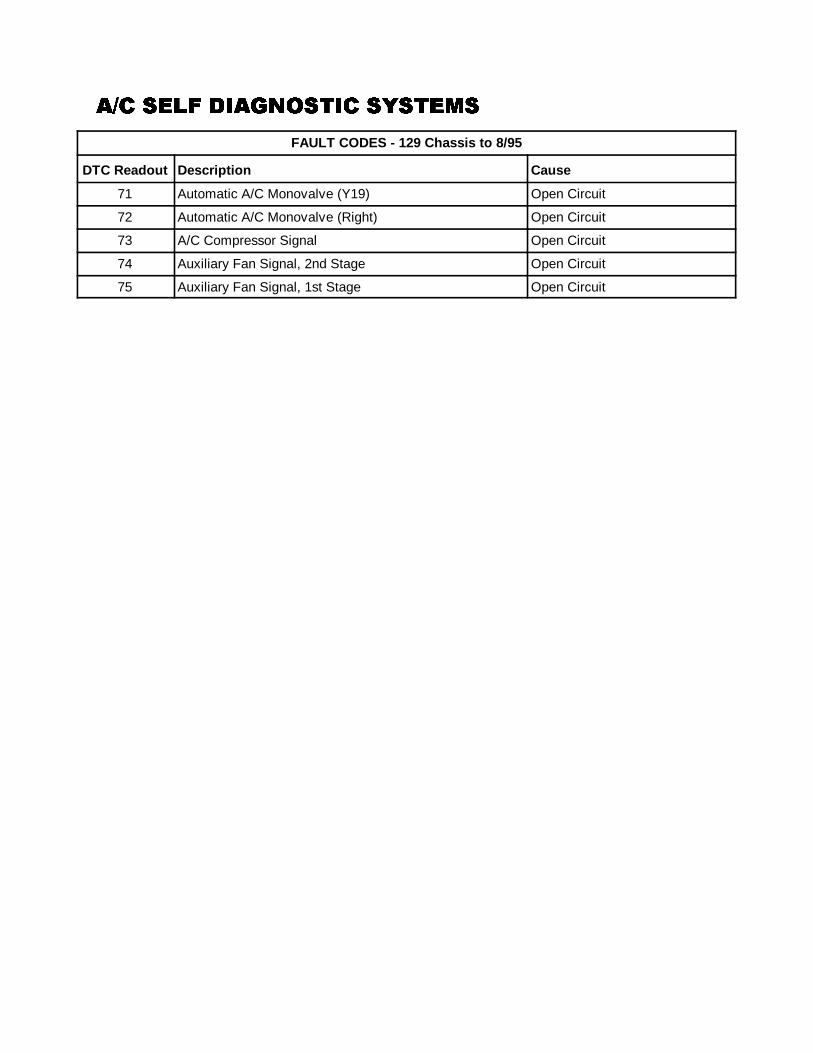
�)� ���� ��2������ ��������)� ���� ��2������ ��������)� ���� ��2������ ��������)� ���� ��2������ �������
FAULT CODES - 129 Chassis to 8/95
DTC Readout Description Cause
89
71 Automatic A/C Monovalve (Y19) Open Circuit
72 Automatic A/C Monovalve (Right) Open Circuit
73 A/C Compressor Signal Open Circuit
74 Auxiliary Fan Signal, 2nd Stage Open Circuit
75 Auxiliary Fan Signal, 1st Stage Open Circuit
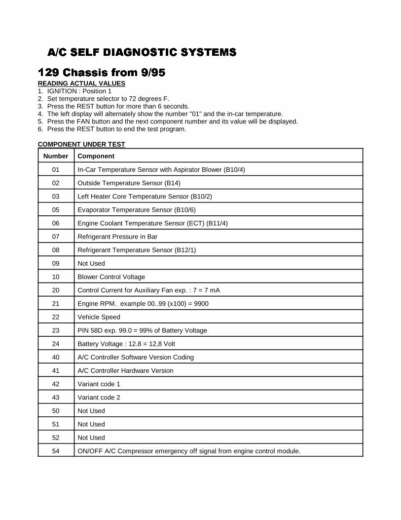
�)� ���� ��2������ ��������)� ���� ��2������ ��������)� ���� ��2������ ��������)� ���� ��2������ �������
90
647 �+!���� /#�� 7)79647 �+!���� /#�� 7)79647 �+!���� /#�� 7)79647 �+!���� /#�� 7)79READING ACTUAL VALUES1. IGNITION : Position 12. Set temperature selector to 72 degrees F.3. Press the REST button for more than 6 seconds.4. The left display will alternately show the number "01" and the in-car temperature.5. Press the FAN button and the next component number and its value will be displayed.6. Press the REST button to end the test program.
COMPONENT UNDER TEST
Number Component
01 In-Car Temperature Sensor with Aspirator Blower (B10/4)
02 Outside Temperature Sensor (B14)
03 Left Heater Core Temperature Sensor (B10/2)
05 Evaporator Temperature Sensor (B10/6)
06 Engine Coolant Temperature Sensor (ECT) (B11/4)
07 Refrigerant Pressure in Bar
08 Refrigerant Temperature Sensor (B12/1)
09 Not Used
10 Blower Control Voltage
20 Control Current for Auxiliary Fan exp. : 7 = 7 mA
21 Engine RPM. example 00..99 (x100) = 9900
22 Vehicle Speed
23 PIN 58D exp. 99.0 = 99% of Battery Voltage
24 Battery Voltage : 12.8 = 12,8 Volt
40 A/C Controller Software Version Coding
41 A/C Controller Hardware Version
42 Variant code 1
43 Variant code 2
50 Not Used
51 Not Used
52 Not Used
54 ON/OFF A/C Compressor emergency off signal from engine control module.

�)� ���� ��2������ ��������)� ���� ��2������ ��������)� ���� ��2������ ��������)� ���� ��2������ �������
91
60 Roof "OPE" = OPEN, "CLO" = CLOSED
61 Left Air Outlet, Potentiometer Voltage
62 Vacuum Actuator 46, Feedback Potentiometer Voltage
63 Center Air Outlet, Potentiometer Voltage
64 Vacuum Actuator 47, Feedback Potentiometer Voltage
65 Right Air Outlet, Potentiometer Voltage
66 Vacuum Actuator 47, Feedback Potentiometer Voltage
FAULT DIAGNOSIS1. IGNITION : Position 12. Temperature selector wheel : "LO"3. Within 20 seconds press the REST and DEFROST buttons simultaneously for more than 5 seconds.4. The LED in the RECIRCULATE button flashes and "dI A" appears on the display.5. Press the AUTO button until all DTC's are displayed and recorded.6. The current faults are displayed first, then the intermittent faults. "END'" is displayed when all codes have
been displayed.7. To erase codes press AUTO again, "dEL" will be displayed. Press v and ^ simultaneously for more than 5
seconds. The display will then show "---". Press AUTO to cancel the erase.8. IGNITION : OFF to end the test program.
FAULT CODES - 129 Chassis from 9/95
DTC Readout Description
026 CAN Bus Communication
226 In-Car Air Temperature Sensor (B10/4)
227 Outside Air Temperature Sensor (B14)
228 Heater Core Temperature Sensor (B10/2)
230 Evaporator Temperature Sensor (B10/6)
231 Engine Coolant Temperature Sensor (B11/4)
232 Refrigerant Pressure Sensor (B12)
233 Refrigerant Temperature Sensor (B12/1)
241 Refrigerant Level
416 Coolant Circulation Pump (A31m1)
417 Automatic A/C Monovalve (Y19)
419 A/C Compressor Electromagnetic Clutch (A9k1)
420 Closed (Idle) Throttle Speed Increase
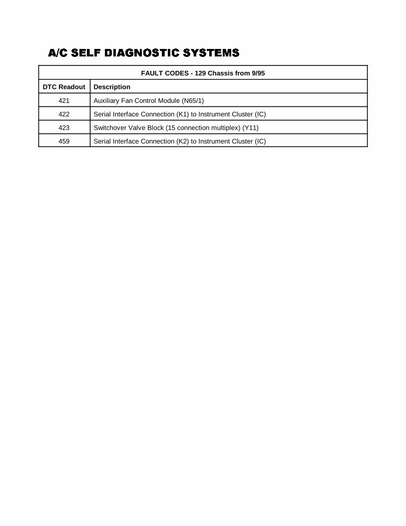
�)� ���� ��2������ ��������)� ���� ��2������ ��������)� ���� ��2������ ��������)� ���� ��2������ �������
FAULT CODES - 129 Chassis from 9/95
DTC Readout Description
92
421 Auxiliary Fan Control Module (N65/1)
422 Serial Interface Connection (K1) to Instrument Cluster (IC)
423 Switchover Valve Block (15 connection multiplex) (Y11)
459 Serial Interface Connection (K2) to Instrument Cluster (IC)
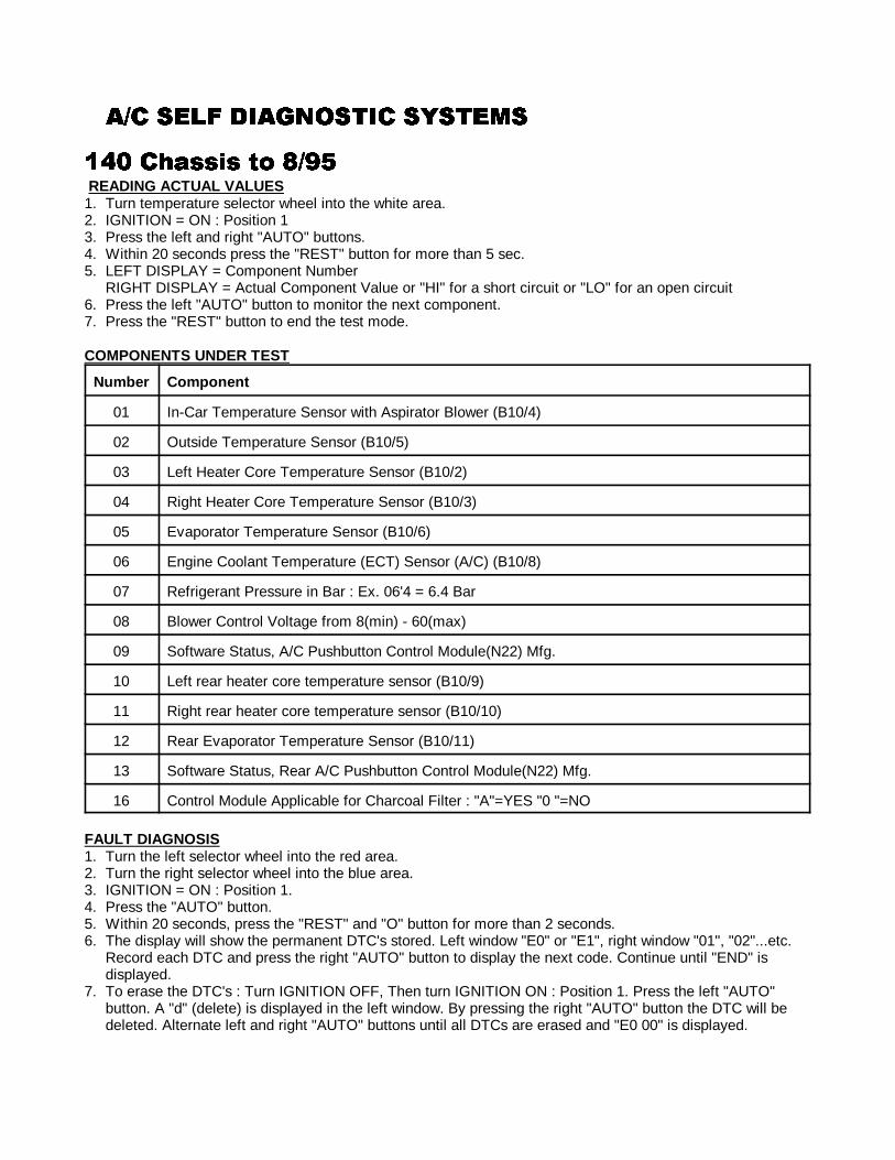
�)� ���� ��2������ ��������)� ���� ��2������ ��������)� ���� ��2������ ��������)� ���� ��2������ �������
93
6-: �+!���� �� 8)796-: �+!���� �� 8)796-: �+!���� �� 8)796-: �+!���� �� 8)79 READING ACTUAL VALUES1. Turn temperature selector wheel into the white area.2. IGNITION = ON : Position 13. Press the left and right "AUTO" buttons.4. Within 20 seconds press the "REST" button for more than 5 sec. 5. LEFT DISPLAY = Component Number
RIGHT DISPLAY = Actual Component Value or "HI" for a short circuit or "LO" for an open circuit6. Press the left "AUTO" button to monitor the next component.7. Press the "REST" button to end the test mode.
COMPONENTS UNDER TEST
Number Component
01 In-Car Temperature Sensor with Aspirator Blower (B10/4)
02 Outside Temperature Sensor (B10/5)
03 Left Heater Core Temperature Sensor (B10/2)
04 Right Heater Core Temperature Sensor (B10/3)
05 Evaporator Temperature Sensor (B10/6)
06 Engine Coolant Temperature (ECT) Sensor (A/C) (B10/8)
07 Refrigerant Pressure in Bar : Ex. 06'4 = 6.4 Bar
08 Blower Control Voltage from 8(min) - 60(max)
09 Software Status, A/C Pushbutton Control Module(N22) Mfg.
10 Left rear heater core temperature sensor (B10/9)
11 Right rear heater core temperature sensor (B10/10)
12 Rear Evaporator Temperature Sensor (B10/11)
13 Software Status, Rear A/C Pushbutton Control Module(N22) Mfg.
16 Control Module Applicable for Charcoal Filter : "A"=YES "0 "=NO
FAULT DIAGNOSIS1. Turn the left selector wheel into the red area.2. Turn the right selector wheel into the blue area.3. IGNITION = ON : Position 1.4. Press the "AUTO" button.5. Within 20 seconds, press the "REST" and "O" button for more than 2 seconds.6. The display will show the permanent DTC's stored. Left window "E0" or "E1", right window "01", "02"...etc.
Record each DTC and press the right "AUTO" button to display the next code. Continue until "END" isdisplayed.
7. To erase the DTC's : Turn IGNITION OFF, Then turn IGNITION ON : Position 1. Press the left "AUTO"button. A "d" (delete) is displayed in the left window. By pressing the right "AUTO" button the DTC will bedeleted. Alternate left and right "AUTO" buttons until all DTCs are erased and "E0 00" is displayed.
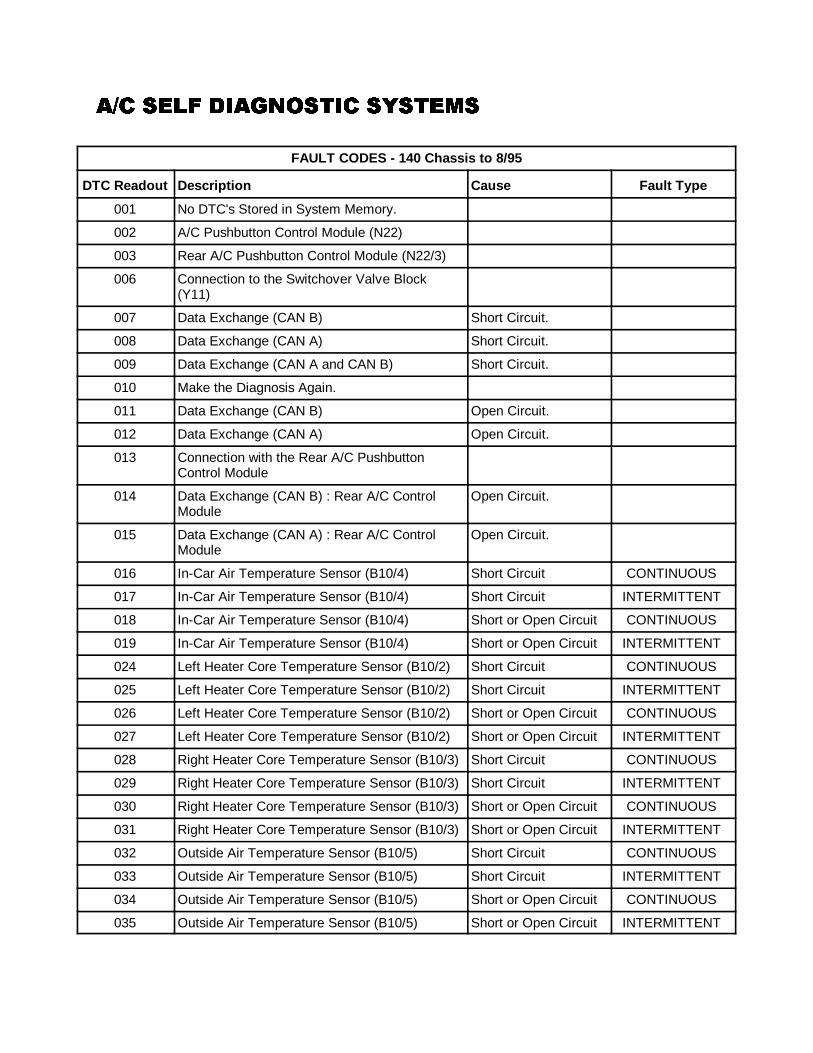
�)� ���� ��2������ ��������)� ���� ��2������ ��������)� ���� ��2������ ��������)� ���� ��2������ �������
94
FAULT CODES - 140 Chassis to 8/95
DTC Readout Description Cause Fault Type
001 No DTC's Stored in System Memory.
002 A/C Pushbutton Control Module (N22)
003 Rear A/C Pushbutton Control Module (N22/3)
006 Connection to the Switchover Valve Block(Y11)
007 Data Exchange (CAN B) Short Circuit.
008 Data Exchange (CAN A) Short Circuit.
009 Data Exchange (CAN A and CAN B) Short Circuit.
010 Make the Diagnosis Again.
011 Data Exchange (CAN B) Open Circuit.
012 Data Exchange (CAN A) Open Circuit.
013 Connection with the Rear A/C PushbuttonControl Module
014 Data Exchange (CAN B) : Rear A/C ControlModule
Open Circuit.
015 Data Exchange (CAN A) : Rear A/C ControlModule
Open Circuit.
016 In-Car Air Temperature Sensor (B10/4) Short Circuit CONTINUOUS
017 In-Car Air Temperature Sensor (B10/4) Short Circuit INTERMITTENT
018 In-Car Air Temperature Sensor (B10/4) Short or Open Circuit CONTINUOUS
019 In-Car Air Temperature Sensor (B10/4) Short or Open Circuit INTERMITTENT
024 Left Heater Core Temperature Sensor (B10/2) Short Circuit CONTINUOUS
025 Left Heater Core Temperature Sensor (B10/2) Short Circuit INTERMITTENT
026 Left Heater Core Temperature Sensor (B10/2) Short or Open Circuit CONTINUOUS
027 Left Heater Core Temperature Sensor (B10/2) Short or Open Circuit INTERMITTENT
028 Right Heater Core Temperature Sensor (B10/3) Short Circuit CONTINUOUS
029 Right Heater Core Temperature Sensor (B10/3) Short Circuit INTERMITTENT
030 Right Heater Core Temperature Sensor (B10/3) Short or Open Circuit CONTINUOUS
031 Right Heater Core Temperature Sensor (B10/3) Short or Open Circuit INTERMITTENT
032 Outside Air Temperature Sensor (B10/5) Short Circuit CONTINUOUS
033 Outside Air Temperature Sensor (B10/5) Short Circuit INTERMITTENT
034 Outside Air Temperature Sensor (B10/5) Short or Open Circuit CONTINUOUS
035 Outside Air Temperature Sensor (B10/5) Short or Open Circuit INTERMITTENT
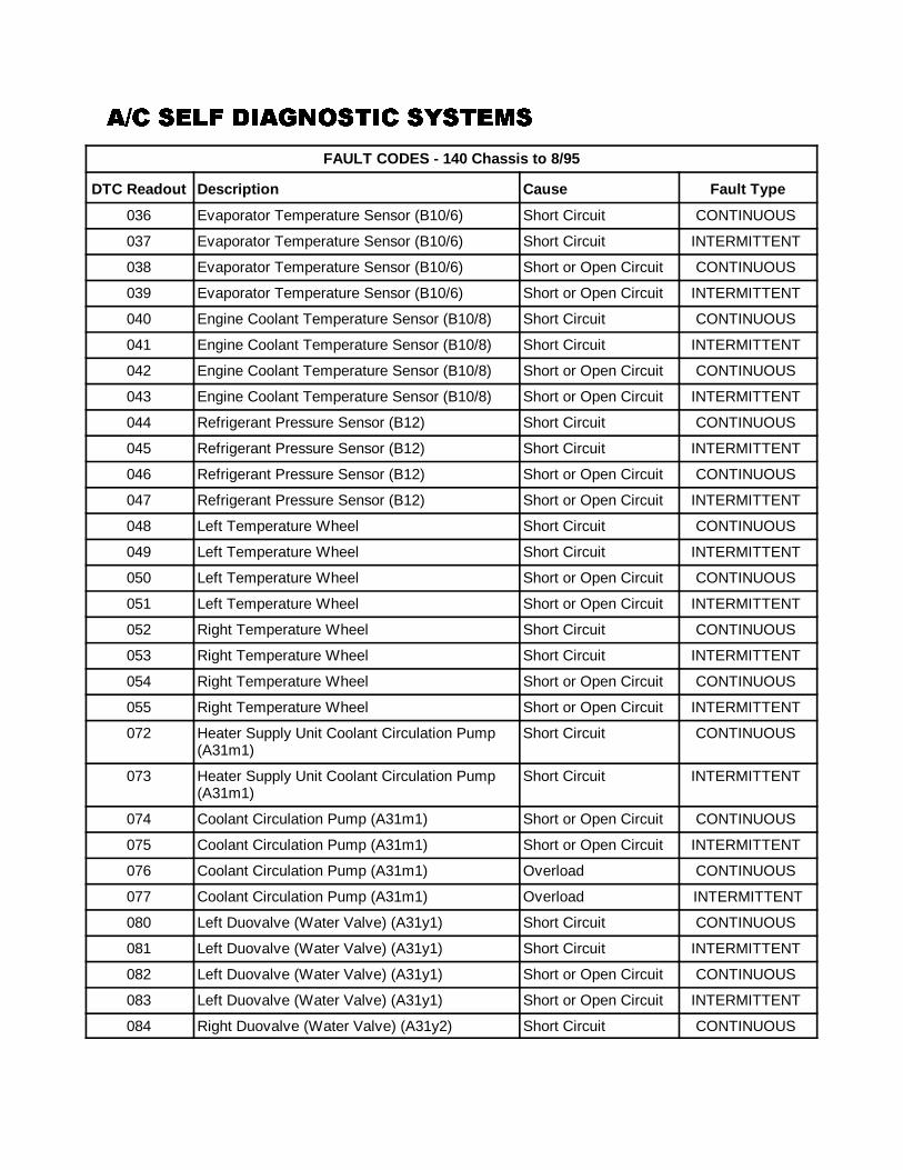
�)� ���� ��2������ ��������)� ���� ��2������ ��������)� ���� ��2������ ��������)� ���� ��2������ �������
FAULT CODES - 140 Chassis to 8/95
DTC Readout Description Cause Fault Type
95
036 Evaporator Temperature Sensor (B10/6) Short Circuit CONTINUOUS
037 Evaporator Temperature Sensor (B10/6) Short Circuit INTERMITTENT
038 Evaporator Temperature Sensor (B10/6) Short or Open Circuit CONTINUOUS
039 Evaporator Temperature Sensor (B10/6) Short or Open Circuit INTERMITTENT
040 Engine Coolant Temperature Sensor (B10/8) Short Circuit CONTINUOUS
041 Engine Coolant Temperature Sensor (B10/8) Short Circuit INTERMITTENT
042 Engine Coolant Temperature Sensor (B10/8) Short or Open Circuit CONTINUOUS
043 Engine Coolant Temperature Sensor (B10/8) Short or Open Circuit INTERMITTENT
044 Refrigerant Pressure Sensor (B12) Short Circuit CONTINUOUS
045 Refrigerant Pressure Sensor (B12) Short Circuit INTERMITTENT
046 Refrigerant Pressure Sensor (B12) Short or Open Circuit CONTINUOUS
047 Refrigerant Pressure Sensor (B12) Short or Open Circuit INTERMITTENT
048 Left Temperature Wheel Short Circuit CONTINUOUS
049 Left Temperature Wheel Short Circuit INTERMITTENT
050 Left Temperature Wheel Short or Open Circuit CONTINUOUS
051 Left Temperature Wheel Short or Open Circuit INTERMITTENT
052 Right Temperature Wheel Short Circuit CONTINUOUS
053 Right Temperature Wheel Short Circuit INTERMITTENT
054 Right Temperature Wheel Short or Open Circuit CONTINUOUS
055 Right Temperature Wheel Short or Open Circuit INTERMITTENT
072 Heater Supply Unit Coolant Circulation Pump(A31m1)
Short Circuit CONTINUOUS
073 Heater Supply Unit Coolant Circulation Pump(A31m1)
Short Circuit INTERMITTENT
074 Coolant Circulation Pump (A31m1) Short or Open Circuit CONTINUOUS
075 Coolant Circulation Pump (A31m1) Short or Open Circuit INTERMITTENT
076 Coolant Circulation Pump (A31m1) Overload CONTINUOUS
077 Coolant Circulation Pump (A31m1) Overload INTERMITTENT
080 Left Duovalve (Water Valve) (A31y1) Short Circuit CONTINUOUS
081 Left Duovalve (Water Valve) (A31y1) Short Circuit INTERMITTENT
082 Left Duovalve (Water Valve) (A31y1) Short or Open Circuit CONTINUOUS
083 Left Duovalve (Water Valve) (A31y1) Short or Open Circuit INTERMITTENT
084 Right Duovalve (Water Valve) (A31y2) Short Circuit CONTINUOUS
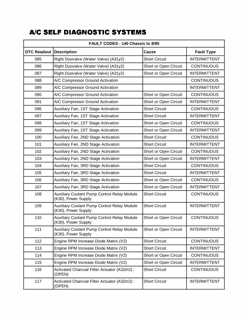
�)� ���� ��2������ ��������)� ���� ��2������ ��������)� ���� ��2������ ��������)� ���� ��2������ �������
FAULT CODES - 140 Chassis to 8/95
DTC Readout Description Cause Fault Type
96
085 Right Duovalve (Water Valve) (A31y2) Short Circuit INTERMITTENT
086 Right Duovalve (Water Valve) (A31y2) Short or Open Circuit CONTINUOUS
087 Right Duovalve (Water Valve) (A31y2) Short or Open Circuit INTERMITTENT
088 A/C Compressor Ground Activation CONTINUOUS
089 A/C Compressor Ground Activation INTERMITTENT
090 A/C Compressor Ground Activation Short or Open Circuit CONTINUOUS
091 A/C Compressor Ground Activation Short or Open Circuit INTERMITTENT
096 Auxiliary Fan, 1ST Stage Activation Short Circuit CONTINUOUS
097 Auxiliary Fan, 1ST Stage Activation Short Circuit INTERMITTENT
098 Auxiliary Fan, 1ST Stage Activation Short or Open Circuit CONTINUOUS
099 Auxiliary Fan, 1ST Stage Activation Short or Open Circuit INTERMITTENT
100 Auxiliary Fan, 2ND Stage Activation Short Circuit CONTINUOUS
101 Auxiliary Fan, 2ND Stage Activation Short Circuit INTERMITTENT
102 Auxiliary Fan, 2ND Stage Activation Short or Open Circuit CONTINUOUS
103 Auxiliary Fan, 2ND Stage Activation Short or Open Circuit INTERMITTENT
104 Auxiliary Fan, 3RD Stage Activation Short Circuit CONTINUOUS
105 Auxiliary Fan, 3RD Stage Activation Short Circuit INTERMITTENT
106 Auxiliary Fan, 3RD Stage Activation Short or Open Circuit CONTINUOUS
107 Auxiliary Fan, 3RD Stage Activation Short or Open Circuit INTERMITTENT
108 Auxiliary Coolant Pump Control Relay Module(K30), Power Supply
Short Circuit CONTINUOUS
109 Auxiliary Coolant Pump Control Relay Module(K30), Power Supply
Short Circuit INTERMITTENT
110 Auxiliary Coolant Pump Control Relay Module(K30), Power Supply
Short or Open Circuit CONTINUOUS
111 Auxiliary Coolant Pump Control Relay Module(K30), Power Supply
Short or Open Circuit INTERMITTENT
112 Engine RPM Increase Diode Matrix (V2) Short Circuit CONTINUOUS
113 Engine RPM Increase Diode Matrix (V2) Short Circuit INTERMITTENT
114 Engine RPM Increase Diode Matrix (V2) Short or Open Circuit CONTINUOUS
115 Engine RPM Increase Diode Matrix (V2) Short or Open Circuit INTERMITTENT
116 Activated Charcoal Filter Actuator (A32m2) :(OPEN)
Short Circuit CONTINUOUS
117 Activated Charcoal Filter Actuator (A32m2) :(OPEN)
Short Circuit INTERMITTENT
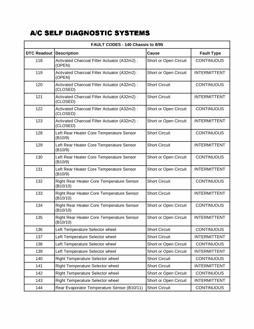
�)� ���� ��2������ ��������)� ���� ��2������ ��������)� ���� ��2������ ��������)� ���� ��2������ �������
FAULT CODES - 140 Chassis to 8/95
DTC Readout Description Cause Fault Type
97
118 Activated Charcoal Filter Actuator (A32m2) :(OPEN)
Short or Open Circuit CONTINUOUS
119 Activated Charcoal Filter Actuator (A32m2) :(OPEN)
Short or Open Circuit INTERMITTENT
120 Activated Charcoal Filter Actuator (A32m2) :(CLOSED)
Short Circuit CONTINUOUS
121 Activated Charcoal Filter Actuator (A32m2) :(CLOSED)
Short Circuit INTERMITTENT
122 Activated Charcoal Filter Actuator (A32m2) :(CLOSED)
Short or Open Circuit CONTINUOUS
123 Activated Charcoal Filter Actuator (A32m2) :(CLOSED)
Short or Open Circuit INTERMITTENT
128 Left Rear Heater Core Temperature Sensor(B10/9)
Short Circuit CONTINUOUS
129 Left Rear Heater Core Temperature Sensor(B10/9)
Short Circuit INTERMITTENT
130 Left Rear Heater Core Temperature Sensor(B10/9)
Short or Open Circuit CONTINUOUS
131 Left Rear Heater Core Temperature Sensor(B10/9)
Short or Open Circuit INTERMITTENT
132 Right Rear Heater Core Temperature Sensor(B10/10)
Short Circuit CONTINUOUS
133 Right Rear Heater Core Temperature Sensor(B10/10)
Short Circuit INTERMITTENT
134 Right Rear Heater Core Temperature Sensor(B10/10)
Short or Open Circuit CONTINUOUS
135 Right Rear Heater Core Temperature Sensor(B10/10)
Short or Open Circuit INTERMITTENT
136 Left Temperature Selector wheel Short Circuit CONTINUOUS
137 Left Temperature Selector wheel Short Circuit INTERMITTENT
138 Left Temperature Selector wheel Short or Open Circuit CONTINUOUS
139 Left Temperature Selector wheel Short or Open Circuit INTERMITTENT
140 Right Temperature Selector wheel Short Circuit CONTINUOUS
141 Right Temperature Selector wheel Short Circuit INTERMITTENT
142 Right Temperature Selector wheel Short or Open Circuit CONTINUOUS
143 Right Temperature Selector wheel Short or Open Circuit INTERMITTENT
144 Rear Evaporator Temperature Sensor (B10/11) Short Circuit CONTINUOUS
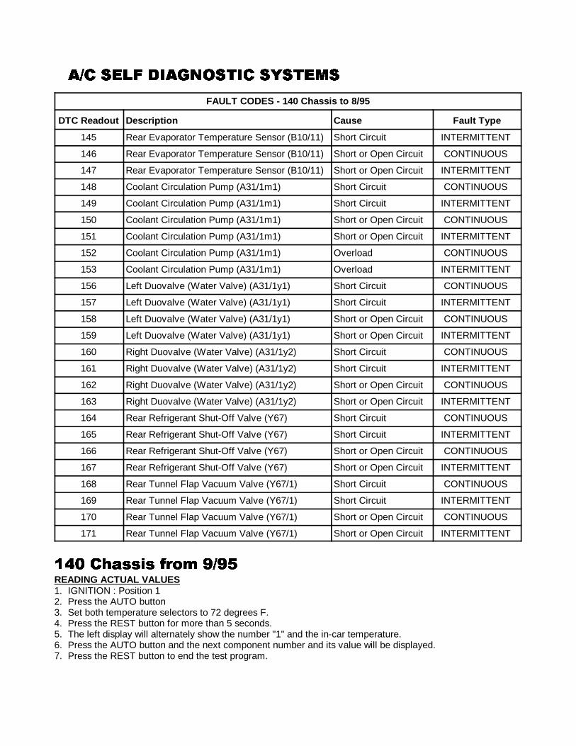
�)� ���� ��2������ ��������)� ���� ��2������ ��������)� ���� ��2������ ��������)� ���� ��2������ �������
FAULT CODES - 140 Chassis to 8/95
DTC Readout Description Cause Fault Type
98
145 Rear Evaporator Temperature Sensor (B10/11) Short Circuit INTERMITTENT
146 Rear Evaporator Temperature Sensor (B10/11) Short or Open Circuit CONTINUOUS
147 Rear Evaporator Temperature Sensor (B10/11) Short or Open Circuit INTERMITTENT
148 Coolant Circulation Pump (A31/1m1) Short Circuit CONTINUOUS
149 Coolant Circulation Pump (A31/1m1) Short Circuit INTERMITTENT
150 Coolant Circulation Pump (A31/1m1) Short or Open Circuit CONTINUOUS
151 Coolant Circulation Pump (A31/1m1) Short or Open Circuit INTERMITTENT
152 Coolant Circulation Pump (A31/1m1) Overload CONTINUOUS
153 Coolant Circulation Pump (A31/1m1) Overload INTERMITTENT
156 Left Duovalve (Water Valve) (A31/1y1) Short Circuit CONTINUOUS
157 Left Duovalve (Water Valve) (A31/1y1) Short Circuit INTERMITTENT
158 Left Duovalve (Water Valve) (A31/1y1) Short or Open Circuit CONTINUOUS
159 Left Duovalve (Water Valve) (A31/1y1) Short or Open Circuit INTERMITTENT
160 Right Duovalve (Water Valve) (A31/1y2) Short Circuit CONTINUOUS
161 Right Duovalve (Water Valve) (A31/1y2) Short Circuit INTERMITTENT
162 Right Duovalve (Water Valve) (A31/1y2) Short or Open Circuit CONTINUOUS
163 Right Duovalve (Water Valve) (A31/1y2) Short or Open Circuit INTERMITTENT
164 Rear Refrigerant Shut-Off Valve (Y67) Short Circuit CONTINUOUS
165 Rear Refrigerant Shut-Off Valve (Y67) Short Circuit INTERMITTENT
166 Rear Refrigerant Shut-Off Valve (Y67) Short or Open Circuit CONTINUOUS
167 Rear Refrigerant Shut-Off Valve (Y67) Short or Open Circuit INTERMITTENT
168 Rear Tunnel Flap Vacuum Valve (Y67/1) Short Circuit CONTINUOUS
169 Rear Tunnel Flap Vacuum Valve (Y67/1) Short Circuit INTERMITTENT
170 Rear Tunnel Flap Vacuum Valve (Y67/1) Short or Open Circuit CONTINUOUS
171 Rear Tunnel Flap Vacuum Valve (Y67/1) Short or Open Circuit INTERMITTENT
6-: �+!���� /#�� 7)796-: �+!���� /#�� 7)796-: �+!���� /#�� 7)796-: �+!���� /#�� 7)79READING ACTUAL VALUES1. IGNITION : Position 12. Press the AUTO button3. Set both temperature selectors to 72 degrees F.4. Press the REST button for more than 5 seconds.5. The left display will alternately show the number "1" and the in-car temperature.6. Press the AUTO button and the next component number and its value will be displayed.7. Press the REST button to end the test program.
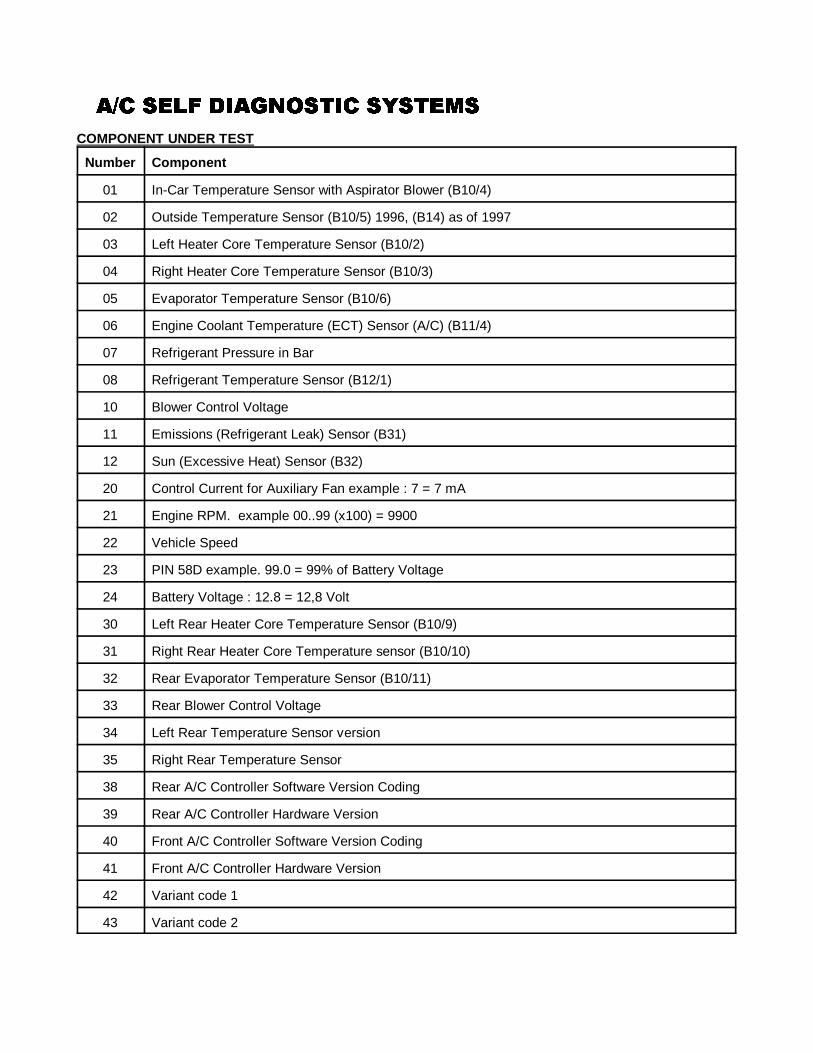
�)� ���� ��2������ ��������)� ���� ��2������ ��������)� ���� ��2������ ��������)� ���� ��2������ �������
99
COMPONENT UNDER TEST
Number Component
01 In-Car Temperature Sensor with Aspirator Blower (B10/4)
02 Outside Temperature Sensor (B10/5) 1996, (B14) as of 1997
03 Left Heater Core Temperature Sensor (B10/2)
04 Right Heater Core Temperature Sensor (B10/3)
05 Evaporator Temperature Sensor (B10/6)
06 Engine Coolant Temperature (ECT) Sensor (A/C) (B11/4)
07 Refrigerant Pressure in Bar
08 Refrigerant Temperature Sensor (B12/1)
10 Blower Control Voltage
11 Emissions (Refrigerant Leak) Sensor (B31)
12 Sun (Excessive Heat) Sensor (B32)
20 Control Current for Auxiliary Fan example : 7 = 7 mA
21 Engine RPM. example 00..99 (x100) = 9900
22 Vehicle Speed
23 PIN 58D example. 99.0 = 99% of Battery Voltage
24 Battery Voltage : 12.8 = 12,8 Volt
30 Left Rear Heater Core Temperature Sensor (B10/9)
31 Right Rear Heater Core Temperature sensor (B10/10)
32 Rear Evaporator Temperature Sensor (B10/11)
33 Rear Blower Control Voltage
34 Left Rear Temperature Sensor version
35 Right Rear Temperature Sensor
38 Rear A/C Controller Software Version Coding
39 Rear A/C Controller Hardware Version
40 Front A/C Controller Software Version Coding
41 Front A/C Controller Hardware Version
42 Variant code 1
43 Variant code 2
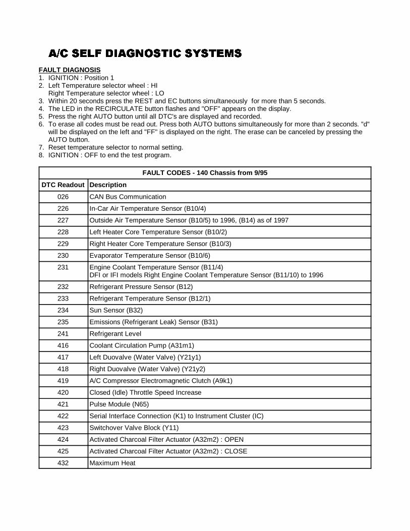
�)� ���� ��2������ ��������)� ���� ��2������ ��������)� ���� ��2������ ��������)� ���� ��2������ �������
100
FAULT DIAGNOSIS1. IGNITION : Position 12. Left Temperature selector wheel : HI
Right Temperature selector wheel : LO3. Within 20 seconds press the REST and EC buttons simultaneously for more than 5 seconds.4. The LED in the RECIRCULATE button flashes and "OFF" appears on the display.5. Press the right AUTO button until all DTC's are displayed and recorded.6. To erase all codes must be read out. Press both AUTO buttons simultaneously for more than 2 seconds. "d"
will be displayed on the left and "FF" is displayed on the right. The erase can be canceled by pressing theAUTO button.
7. Reset temperature selector to normal setting.8. IGNITION : OFF to end the test program.
FAULT CODES - 140 Chassis from 9/95
DTC Readout Description
026 CAN Bus Communication
226 In-Car Air Temperature Sensor (B10/4)
227 Outside Air Temperature Sensor (B10/5) to 1996, (B14) as of 1997
228 Left Heater Core Temperature Sensor (B10/2)
229 Right Heater Core Temperature Sensor (B10/3)
230 Evaporator Temperature Sensor (B10/6)
231 Engine Coolant Temperature Sensor (B11/4) DFI or IFI models Right Engine Coolant Temperature Sensor (B11/10) to 1996
232 Refrigerant Pressure Sensor (B12)
233 Refrigerant Temperature Sensor (B12/1)
234 Sun Sensor (B32)
235 Emissions (Refrigerant Leak) Sensor (B31)
241 Refrigerant Level
416 Coolant Circulation Pump (A31m1)
417 Left Duovalve (Water Valve) (Y21y1)
418 Right Duovalve (Water Valve) (Y21y2)
419 A/C Compressor Electromagnetic Clutch (A9k1)
420 Closed (Idle) Throttle Speed Increase
421 Pulse Module (N65)
422 Serial Interface Connection (K1) to Instrument Cluster (IC)
423 Switchover Valve Block (Y11)
424 Activated Charcoal Filter Actuator (A32m2) : OPEN
425 Activated Charcoal Filter Actuator (A32m2) : CLOSE
432 Maximum Heat
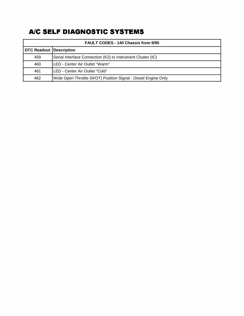
�)� ���� ��2������ ��������)� ���� ��2������ ��������)� ���� ��2������ ��������)� ���� ��2������ �������
FAULT CODES - 140 Chassis from 9/95
DTC Readout Description
101
459 Serial Interface Connection (K2) to Instrument Cluster (IC)
460 LED - Center Air Outlet "Warm"
461 LED - Center Air Outlet "Cold"
462 Wide Open Throttle (WOT) Position Signal - Diesel Engine Only
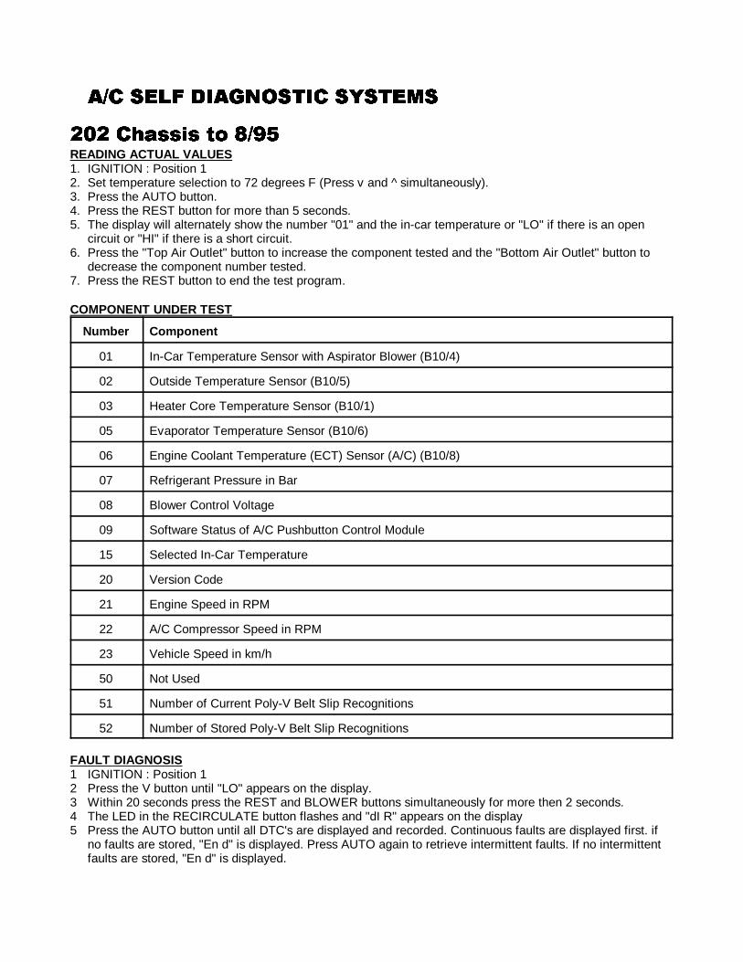
�)� ���� ��2������ ��������)� ���� ��2������ ��������)� ���� ��2������ ��������)� ���� ��2������ �������
102
4:4 �+!���� �� 8)794:4 �+!���� �� 8)794:4 �+!���� �� 8)794:4 �+!���� �� 8)79READING ACTUAL VALUES1. IGNITION : Position 12. Set temperature selection to 72 degrees F (Press v and ^ simultaneously).3. Press the AUTO button.4. Press the REST button for more than 5 seconds.5. The display will alternately show the number "01" and the in-car temperature or "LO" if there is an open
circuit or "HI" if there is a short circuit.6. Press the "Top Air Outlet" button to increase the component tested and the "Bottom Air Outlet" button to
decrease the component number tested.7. Press the REST button to end the test program.
COMPONENT UNDER TEST
Number Component
01 In-Car Temperature Sensor with Aspirator Blower (B10/4)
02 Outside Temperature Sensor (B10/5)
03 Heater Core Temperature Sensor (B10/1)
05 Evaporator Temperature Sensor (B10/6)
06 Engine Coolant Temperature (ECT) Sensor (A/C) (B10/8)
07 Refrigerant Pressure in Bar
08 Blower Control Voltage
09 Software Status of A/C Pushbutton Control Module
15 Selected In-Car Temperature
20 Version Code
21 Engine Speed in RPM
22 A/C Compressor Speed in RPM
23 Vehicle Speed in km/h
50 Not Used
51 Number of Current Poly-V Belt Slip Recognitions
52 Number of Stored Poly-V Belt Slip Recognitions
FAULT DIAGNOSIS1 IGNITION : Position 12 Press the V button until "LO" appears on the display.3 Within 20 seconds press the REST and BLOWER buttons simultaneously for more then 2 seconds.4 The LED in the RECIRCULATE button flashes and "dI R" appears on the display5 Press the AUTO button until all DTC's are displayed and recorded. Continuous faults are displayed first. if
no faults are stored, "En d" is displayed. Press AUTO again to retrieve intermittent faults. If no intermittentfaults are stored, "En d" is displayed.
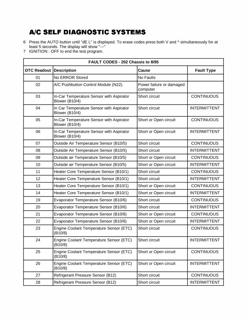
�)� ���� ��2������ ��������)� ���� ��2������ ��������)� ���� ��2������ ��������)� ���� ��2������ �������
103
6 Press the AUTO button until "dE L" is displayed. To erase codes press both V and ^ simultaneously for atleast 5 seconds. The display will show "---"
7 IGNITION : OFF to end the test program.
FAULT CODES - 202 Chassis to 8/95
DTC Readout Description Cause Fault Type
01 No ERROR Stored No Faults
02 A/C Pushbutton Control Module (N22). Power failure or damagedcomputer
03 In-Car Temperature Sensor with AspiratorBlower (B10/4)
Short circuit CONTINUOUS
04 In Car Temperature Sensor with AspiratorBlower (B10/4)
Short circuit INTERMITTENT
05 In-Car Temperature Sensor with AspiratorBlower (B10/4)
Short or Open circuit CONTINUOUS
06 In-Car Temperature Sensor with AspiratorBlower (B10/4)
Short or Open circuit INTERMITTENT
07 Outside Air Temperature Sensor (B10/5) Short circuit CONTINUOUS
08 Outside Air Temperature Sensor (B10/5) Short circuit INTERMITTENT
09 Outside air Temperature Sensor (B10/5) Short or Open circuit CONTINUOUS
10 Outside air Temperature Sensor (B10/5) Short or Open circuit INTERMITTENT
11 Heater Core Temperature Sensor (B10/1) Short circuit CONTINUOUS
12 Heater Core Temperature Sensor (B10/1) Short circuit INTERMITTENT
13 Heater Core Temperature Sensor (B10/1) Short or Open circuit CONTINUOUS
14 Heater Core Temperature Sensor (B10/1) Short or Open circuit INTERMITTENT
19 Evaporator Temperature Sensor (B10/6) Short circuit CONTINUOUS
20 Evaporator Temperature Sensor (B10/6) Short circuit INTERMITTENT
21 Evaporator Temperature Sensor (B10/6) Short or Open circuit CONTINUOUS
22 Evaporator Temperature Sensor (B10/6) Short or Open circuit INTERMITTENT
23 Engine Coolant Temperature Sensor (ETC)(B10/8)
Short circuit CONTINUOUS
24 Engine Coolant Temperature Sensor (ETC)(B10/8)
Short circuit INTERMITTENT
25 Engine Coolant Temperature Sensor (ETC)(B10/8)
Short or Open circuit CONTINUOUS
26 Engine Coolant Temperature Sensor (ETC)(B10/8)
Short or Open circuit INTERMITTENT
27 Refrigerant Pressure Sensor (B12) Short circuit CONTINUOUS
28 Refrigerant Pressure Sensor (B12) Short circuit INTERMITTENT
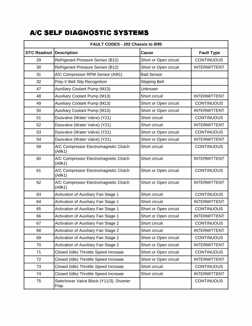
�)� ���� ��2������ ��������)� ���� ��2������ ��������)� ���� ��2������ ��������)� ���� ��2������ �������
FAULT CODES - 202 Chassis to 8/95
DTC Readout Description Cause Fault Type
104
29 Refrigerant Pressure Sensor (B12) Short or Open circuit CONTINUOUS
30 Refrigerant Pressure Sensor (B12) Short or Open circuit INTERMITTENT
31 A/C Compressor RPM Sensor (A9l1) Bad Sensor
32 Poly-V Belt Slip Recognition Slipping Belt
47 Auxiliary Coolant Pump (M13) Unknown
48 Auxiliary Coolant Pump (M13) Short circuit INTERMITTENT
49 Auxiliary Coolant Pump (M13) Short or Open circuit CONTINUOUS
50 Auxiliary Coolant Pump (M13) Short or Open circuit INTERMITTENT
51 Duovalve (Water Valve) (Y21) Short circuit CONTINUOUS
52 Duovalve (Water Valve) (Y21) Short circuit INTERMITTENT
53 Duovalve (Water Valve) (Y21) Short or Open circuit CONTINUOUS
54 Duovalve (Water Valve) (Y21) Short or Open circuit INTERMITTENT
59 A/C Compressor Electromagnetic Clutch(A9k1)
Short circuit CONTINUOUS
60 A/C Compressor Electromagnetic Clutch(A9k1)
Short circuit INTERMITTENT
61 A/C Compressor Electromagnetic Clutch(A9k1)
Short or Open circuit CONTINUOUS
62 A/C Compressor Electromagnetic Clutch(A9k1)
Short or Open circuit INTERMITTENT
63 Activation of Auxiliary Fan Stage 1 Short circuit CONTINUOUS
64 Activation of Auxiliary Fan Stage 1 Short circuit INTERMITTENT
65 Activation of Auxiliary Fan Stage 1 Short or Open circuit CONTINUOUS
66 Activation of Auxiliary Fan Stage 1 Short or Open circuit INTERMITTENT
67 Activation of Auxiliary Fan Stage 2 Short circuit CONTINUOUS
68 Activation of Auxiliary Fan Stage 2 Short circuit INTERMITTENT
69 Activation of Auxiliary Fan Stage 2 Short or Open circuit CONTINUOUS
70 Activation of Auxiliary Fan Stage 2 Short or Open circuit INTERMITTENT
71 Closed (Idle) Throttle Speed Increase Short or Open circuit CONTINUOUS
72 Closed (Idle) Throttle Speed Increase Short or Open circuit INTERMITTENT
73 Closed (Idle) Throttle Speed Increase Short circuit CONTINUOUS
74 Closed (Idle) Throttle Speed Increase Short circuit INTERMITTENT
75 Switchover Valve Block (Y11/3), DiverterFlap
CONTINUOUS
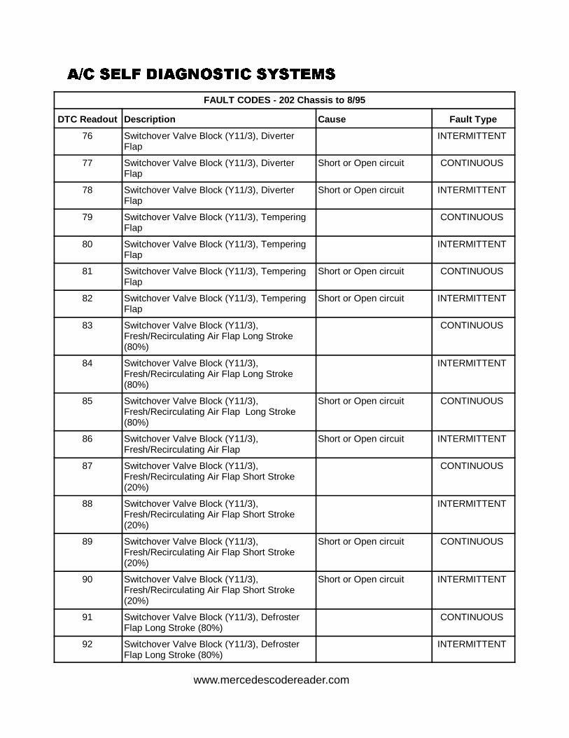
�)� ���� ��2������ ��������)� ���� ��2������ ��������)� ���� ��2������ ��������)� ���� ��2������ �������
FAULT CODES - 202 Chassis to 8/95
DTC Readout Description Cause Fault Type
105
76 Switchover Valve Block (Y11/3), DiverterFlap
INTERMITTENT
77 Switchover Valve Block (Y11/3), DiverterFlap
Short or Open circuit CONTINUOUS
78 Switchover Valve Block (Y11/3), DiverterFlap
Short or Open circuit INTERMITTENT
79 Switchover Valve Block (Y11/3), TemperingFlap
CONTINUOUS
80 Switchover Valve Block (Y11/3), TemperingFlap
INTERMITTENT
81 Switchover Valve Block (Y11/3), TemperingFlap
Short or Open circuit CONTINUOUS
82 Switchover Valve Block (Y11/3), TemperingFlap
Short or Open circuit INTERMITTENT
83 Switchover Valve Block (Y11/3),Fresh/Recirculating Air Flap Long Stroke(80%)
CONTINUOUS
84 Switchover Valve Block (Y11/3),Fresh/Recirculating Air Flap Long Stroke(80%)
INTERMITTENT
85 Switchover Valve Block (Y11/3),Fresh/Recirculating Air Flap Long Stroke(80%)
Short or Open circuit CONTINUOUS
86 Switchover Valve Block (Y11/3),Fresh/Recirculating Air Flap
Short or Open circuit INTERMITTENT
87 Switchover Valve Block (Y11/3),Fresh/Recirculating Air Flap Short Stroke(20%)
CONTINUOUS
88 Switchover Valve Block (Y11/3),Fresh/Recirculating Air Flap Short Stroke(20%)
INTERMITTENT
89 Switchover Valve Block (Y11/3),Fresh/Recirculating Air Flap Short Stroke(20%)
Short or Open circuit CONTINUOUS
90 Switchover Valve Block (Y11/3),Fresh/Recirculating Air Flap Short Stroke(20%)
Short or Open circuit INTERMITTENT
91 Switchover Valve Block (Y11/3), DefrosterFlap Long Stroke (80%)
CONTINUOUS
92 Switchover Valve Block (Y11/3), DefrosterFlap Long Stroke (80%)
INTERMITTENT
www.mercedescodereader.com
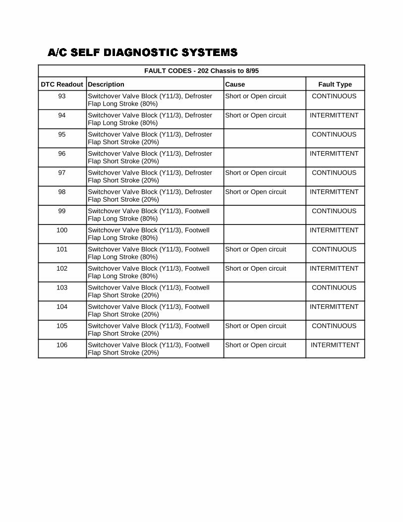
�)� ���� ��2������ ��������)� ���� ��2������ ��������)� ���� ��2������ ��������)� ���� ��2������ �������
FAULT CODES - 202 Chassis to 8/95
DTC Readout Description Cause Fault Type
106
93 Switchover Valve Block (Y11/3), DefrosterFlap Long Stroke (80%)
Short or Open circuit CONTINUOUS
94 Switchover Valve Block (Y11/3), DefrosterFlap Long Stroke (80%)
Short or Open circuit INTERMITTENT
95 Switchover Valve Block (Y11/3), DefrosterFlap Short Stroke (20%)
CONTINUOUS
96 Switchover Valve Block (Y11/3), DefrosterFlap Short Stroke (20%)
INTERMITTENT
97 Switchover Valve Block (Y11/3), DefrosterFlap Short Stroke (20%)
Short or Open circuit CONTINUOUS
98 Switchover Valve Block (Y11/3), DefrosterFlap Short Stroke (20%)
Short or Open circuit INTERMITTENT
99 Switchover Valve Block (Y11/3), FootwellFlap Long Stroke (80%)
CONTINUOUS
100 Switchover Valve Block (Y11/3), FootwellFlap Long Stroke (80%)
INTERMITTENT
101 Switchover Valve Block (Y11/3), FootwellFlap Long Stroke (80%)
Short or Open circuit CONTINUOUS
102 Switchover Valve Block (Y11/3), FootwellFlap Long Stroke (80%)
Short or Open circuit INTERMITTENT
103 Switchover Valve Block (Y11/3), FootwellFlap Short Stroke (20%)
CONTINUOUS
104 Switchover Valve Block (Y11/3), FootwellFlap Short Stroke (20%)
INTERMITTENT
105 Switchover Valve Block (Y11/3), FootwellFlap Short Stroke (20%)
Short or Open circuit CONTINUOUS
106 Switchover Valve Block (Y11/3), FootwellFlap Short Stroke (20%)
Short or Open circuit INTERMITTENT

�)� ���� ��2������ ��������)� ���� ��2������ ��������)� ���� ��2������ ��������)� ���� ��2������ �������
107
4:4 �+!���� /#�� 7)794:4 �+!���� /#�� 7)794:4 �+!���� /#�� 7)794:4 �+!���� /#�� 7)79READING ACTUAL VALUES1. IGNITION : Position 12. Set temperature selector to 72 degrees F.3. Press the REST button for more than 6 seconds.4. The left display will alternately show the number "01" and the in-car temperature.5. Press the FAN button and the next component number and its value will be displayed.6. Press the REST button to end the test program.
COMPONENT UNDER TEST
Number Component
01 In-Car Temperature Sensor with Aspirator Blower (B10/4)
02 Outside Temperature Sensor (B14)
03 Heater Core Temperature Sensor (B10/1)
05 Evaporator Temperature Sensor (B10/6)
06 Engine Coolant Temperature Sensor (ECT) (B11/4)
07 Refrigerant Pressure in Bar
08 Refrigerant Temperature Sensor (B12/1)
09 Not Used
10 Blower Control Voltage
20 Control Current for Auxiliary Fan exp. : 7 = 7 mA
21 Engine RPM. example 00..99 (x100) = 9900
22 Vehicle Speed
23 PIN 58D exp. 99.0 = 99% of Battery Voltage
24 Battery Voltage : 12.8 = 12,8 Volt
40 A/C Controller Software Version Coding
41 A/C Controller Hardware Version
42 Variant code 1
43 Variant code 2
50 Not Used
51 Not Used
52 Not Used
54 ON/OFF A/C Compressor emergency off signal from engine control module.
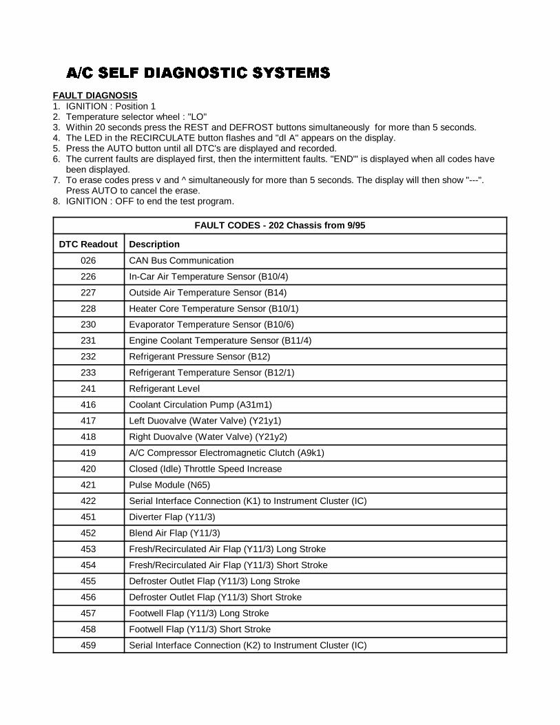
�)� ���� ��2������ ��������)� ���� ��2������ ��������)� ���� ��2������ ��������)� ���� ��2������ �������
108
FAULT DIAGNOSIS1. IGNITION : Position 12. Temperature selector wheel : "LO"3. Within 20 seconds press the REST and DEFROST buttons simultaneously for more than 5 seconds.4. The LED in the RECIRCULATE button flashes and "dI A" appears on the display.5. Press the AUTO button until all DTC's are displayed and recorded.6. The current faults are displayed first, then the intermittent faults. "END'" is displayed when all codes have
been displayed.7. To erase codes press v and ^ simultaneously for more than 5 seconds. The display will then show "---".
Press AUTO to cancel the erase.8. IGNITION : OFF to end the test program.
FAULT CODES - 202 Chassis from 9/95
DTC Readout Description
026 CAN Bus Communication
226 In-Car Air Temperature Sensor (B10/4)
227 Outside Air Temperature Sensor (B14)
228 Heater Core Temperature Sensor (B10/1)
230 Evaporator Temperature Sensor (B10/6)
231 Engine Coolant Temperature Sensor (B11/4)
232 Refrigerant Pressure Sensor (B12)
233 Refrigerant Temperature Sensor (B12/1)
241 Refrigerant Level
416 Coolant Circulation Pump (A31m1)
417 Left Duovalve (Water Valve) (Y21y1)
418 Right Duovalve (Water Valve) (Y21y2)
419 A/C Compressor Electromagnetic Clutch (A9k1)
420 Closed (Idle) Throttle Speed Increase
421 Pulse Module (N65)
422 Serial Interface Connection (K1) to Instrument Cluster (IC)
451 Diverter Flap (Y11/3)
452 Blend Air Flap (Y11/3)
453 Fresh/Recirculated Air Flap (Y11/3) Long Stroke
454 Fresh/Recirculated Air Flap (Y11/3) Short Stroke
455 Defroster Outlet Flap (Y11/3) Long Stroke
456 Defroster Outlet Flap (Y11/3) Short Stroke
457 Footwell Flap (Y11/3) Long Stroke
458 Footwell Flap (Y11/3) Short Stroke
459 Serial Interface Connection (K2) to Instrument Cluster (IC)
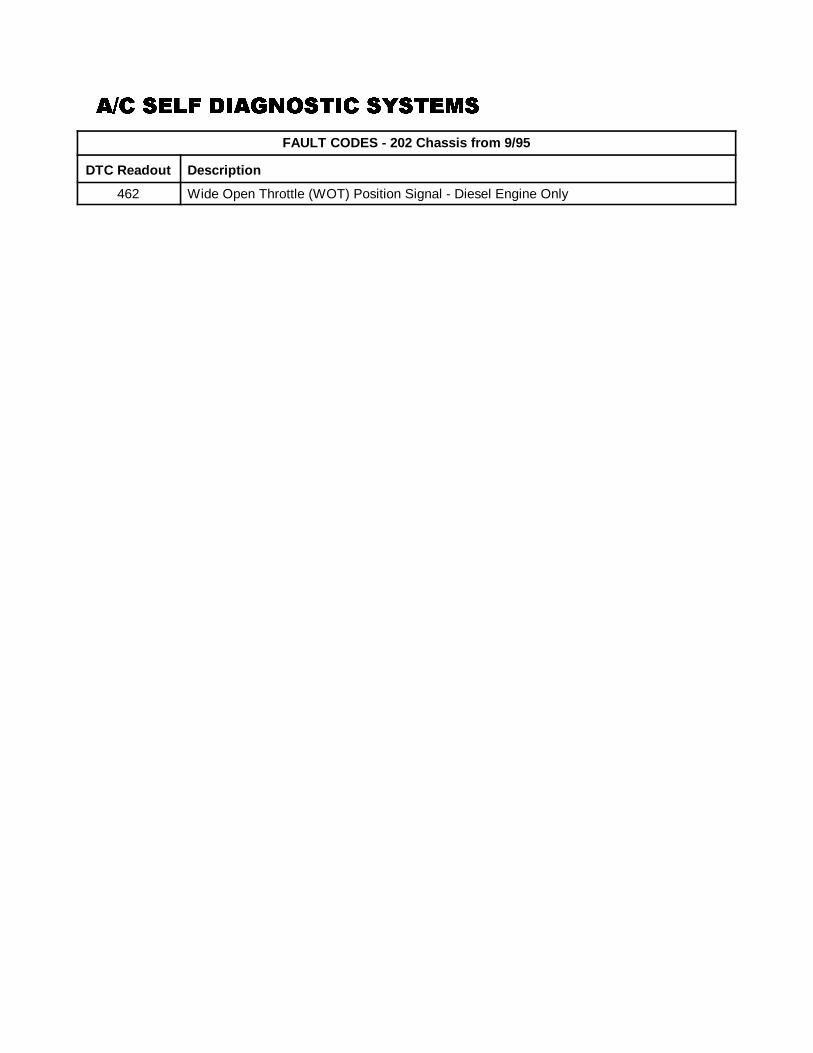
�)� ���� ��2������ ��������)� ���� ��2������ ��������)� ���� ��2������ ��������)� ���� ��2������ �������
FAULT CODES - 202 Chassis from 9/95
DTC Readout Description
109
462 Wide Open Throttle (WOT) Position Signal - Diesel Engine Only
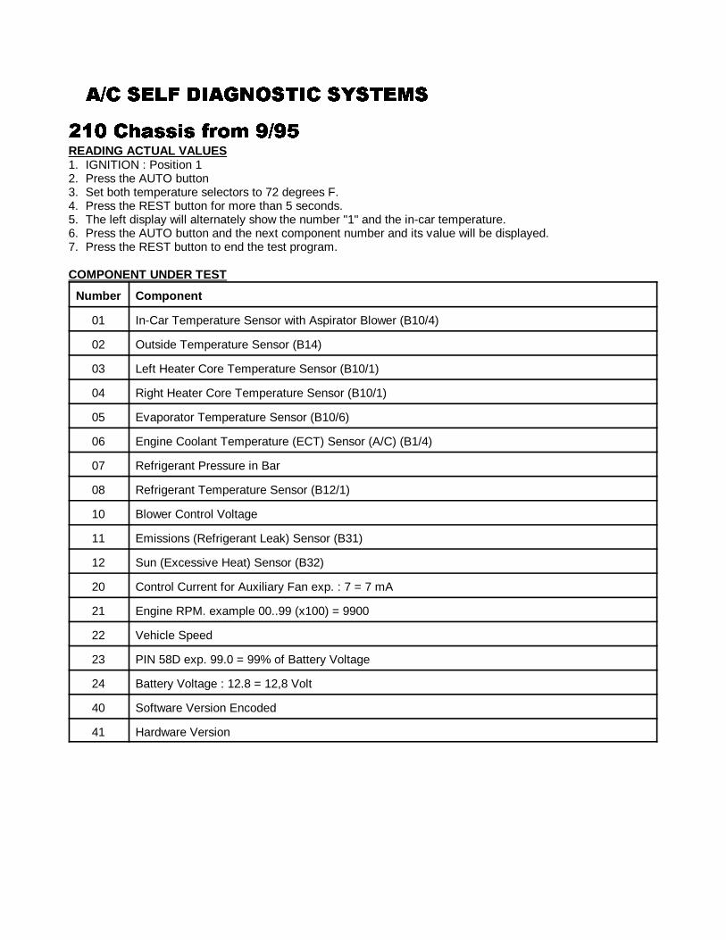
�)� ���� ��2������ ��������)� ���� ��2������ ��������)� ���� ��2������ ��������)� ���� ��2������ �������
110
46: �+!���� /#�� 7)7946: �+!���� /#�� 7)7946: �+!���� /#�� 7)7946: �+!���� /#�� 7)79READING ACTUAL VALUES1. IGNITION : Position 12. Press the AUTO button3. Set both temperature selectors to 72 degrees F.4. Press the REST button for more than 5 seconds.5. The left display will alternately show the number "1" and the in-car temperature.6. Press the AUTO button and the next component number and its value will be displayed.7. Press the REST button to end the test program.
COMPONENT UNDER TEST
Number Component
01 In-Car Temperature Sensor with Aspirator Blower (B10/4)
02 Outside Temperature Sensor (B14)
03 Left Heater Core Temperature Sensor (B10/1)
04 Right Heater Core Temperature Sensor (B10/1)
05 Evaporator Temperature Sensor (B10/6)
06 Engine Coolant Temperature (ECT) Sensor (A/C) (B1/4)
07 Refrigerant Pressure in Bar
08 Refrigerant Temperature Sensor (B12/1)
10 Blower Control Voltage
11 Emissions (Refrigerant Leak) Sensor (B31)
12 Sun (Excessive Heat) Sensor (B32)
20 Control Current for Auxiliary Fan exp. : 7 = 7 mA
21 Engine RPM. example 00..99 (x100) = 9900
22 Vehicle Speed
23 PIN 58D exp. 99.0 = 99% of Battery Voltage
24 Battery Voltage : 12.8 = 12,8 Volt
40 Software Version Encoded
41 Hardware Version
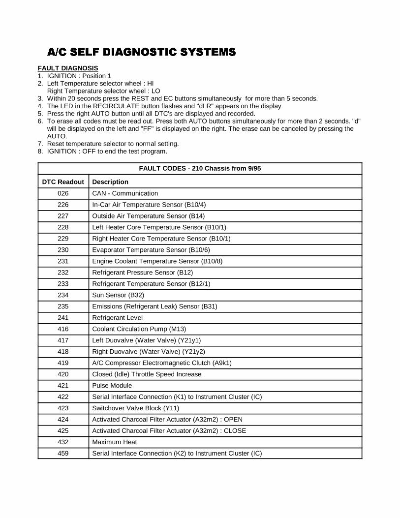
�)� ���� ��2������ ��������)� ���� ��2������ ��������)� ���� ��2������ ��������)� ���� ��2������ �������
111
FAULT DIAGNOSIS1. IGNITION : Position 12. Left Temperature selector wheel : HI
Right Temperature selector wheel : LO3. Within 20 seconds press the REST and EC buttons simultaneously for more than 5 seconds.4. The LED in the RECIRCULATE button flashes and "dI R" appears on the display5. Press the right AUTO button until all DTC's are displayed and recorded.6. To erase all codes must be read out. Press both AUTO buttons simultaneously for more than 2 seconds. "d"
will be displayed on the left and "FF" is displayed on the right. The erase can be canceled by pressing theAUTO.
7. Reset temperature selector to normal setting.8. IGNITION : OFF to end the test program.
FAULT CODES - 210 Chassis from 9/95
DTC Readout Description
026 CAN - Communication
226 In-Car Air Temperature Sensor (B10/4)
227 Outside Air Temperature Sensor (B14)
228 Left Heater Core Temperature Sensor (B10/1)
229 Right Heater Core Temperature Sensor (B10/1)
230 Evaporator Temperature Sensor (B10/6)
231 Engine Coolant Temperature Sensor (B10/8)
232 Refrigerant Pressure Sensor (B12)
233 Refrigerant Temperature Sensor (B12/1)
234 Sun Sensor (B32)
235 Emissions (Refrigerant Leak) Sensor (B31)
241 Refrigerant Level
416 Coolant Circulation Pump (M13)
417 Left Duovalve (Water Valve) (Y21y1)
418 Right Duovalve (Water Valve) (Y21y2)
419 A/C Compressor Electromagnetic Clutch (A9k1)
420 Closed (Idle) Throttle Speed Increase
421 Pulse Module
422 Serial Interface Connection (K1) to Instrument Cluster (IC)
423 Switchover Valve Block (Y11)
424 Activated Charcoal Filter Actuator (A32m2) : OPEN
425 Activated Charcoal Filter Actuator (A32m2) : CLOSE
432 Maximum Heat
459 Serial Interface Connection (K2) to Instrument Cluster (IC)
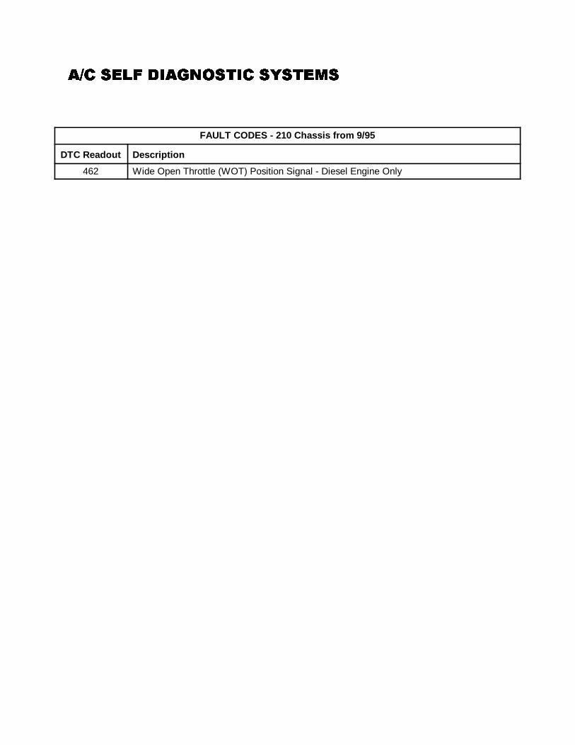
�)� ���� ��2������ ��������)� ���� ��2������ ��������)� ���� ��2������ ��������)� ���� ��2������ �������
FAULT CODES - 210 Chassis from 9/95
DTC Readout Description
112
462 Wide Open Throttle (WOT) Position Signal - Diesel Engine Only
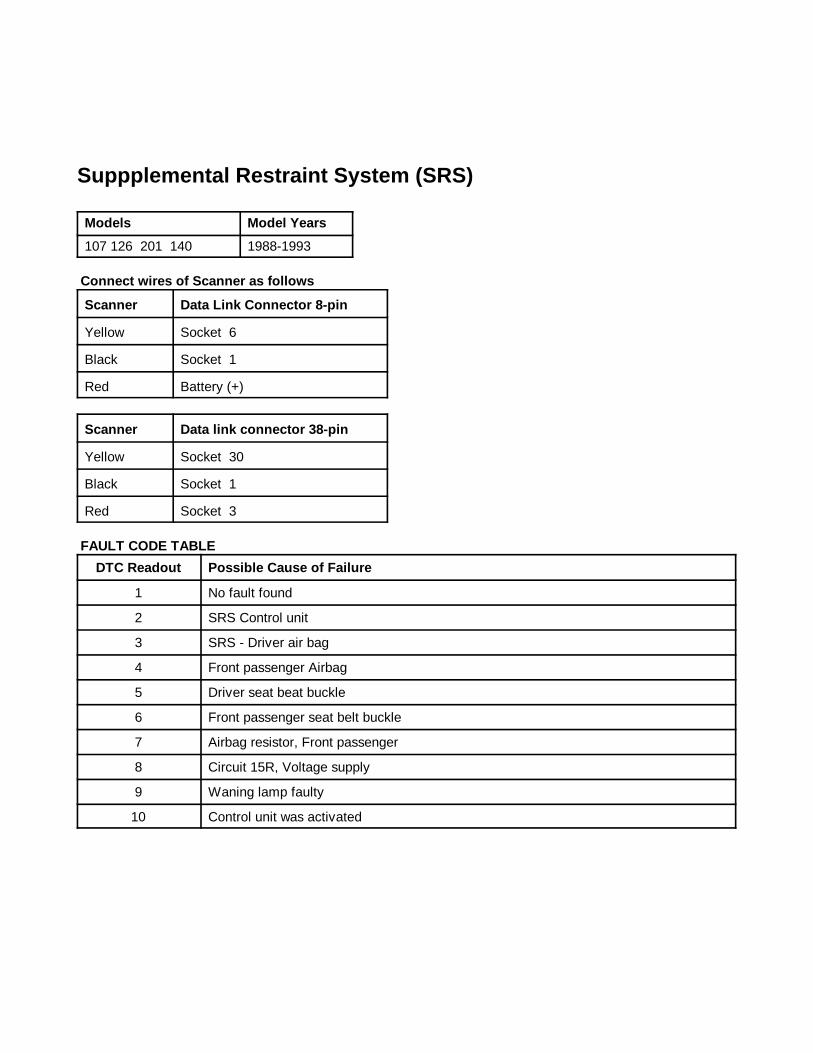
����1 ANALOG CODES CS1000 Code Scanner OB15-11
113
��""������!� ����#!��� ������ ������""������!� ����#!��� ������ ������""������!� ����#!��� ������ ������""������!� ����#!��� ������ ����Models Model Years
107 126 201 140 1988-1993
Connect wires of Scanner as f ollows
Scanner Data Link Connector 8-pin
Yellow Socket 6
Black Socket 1
Red Battery (+)
Scanner Data link connector 38-pin
Yellow Socket 30
Black Socket 1
Red Socket 3
FAULT CODE TABLE
DTC Readout Possible Cause of Failure
1 No fault found
2 SRS Control unit
3 SRS - Driver air bag
4 Front passenger Airbag
5 Driver seat beat buckle
6 Front passenger seat belt buckle
7 Airbag resistor, Front passenger
8 Circuit 15R, Voltage supply
9 Waning lamp faulty
10 Control unit was activated
Suppplemental Restraint System (SRS)
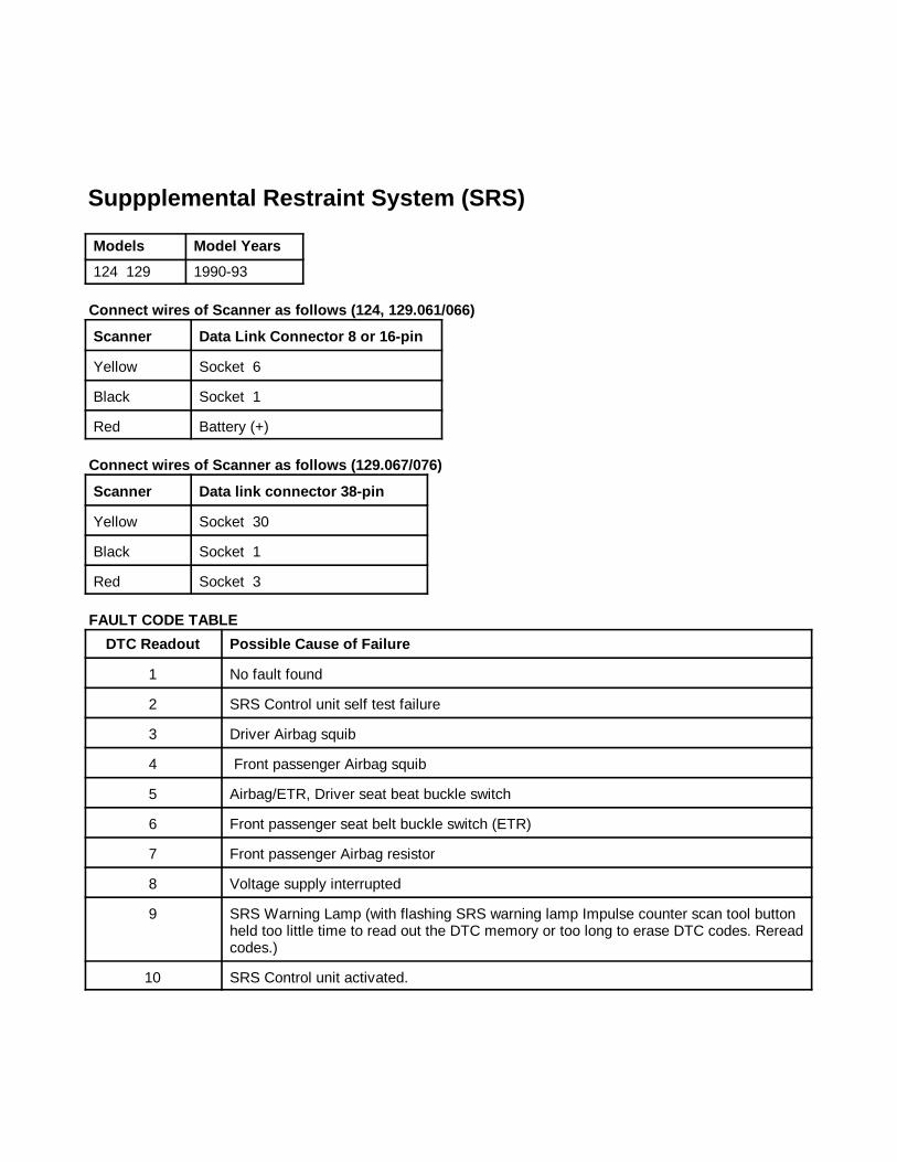
����1 ANALOG CODES CS1000 Code Scanner OB15-11
114
��""������!� ����#!��� ������ ������""������!� ����#!��� ������ ������""������!� ����#!��� ������ ������""������!� ����#!��� ������ ����Models Model Years
124 129 1990-93
Connect wires of Scanner as f ollows ( 124, 129.061/066)
Scanner Data Link Connector 8 or 16-pin
Yellow Socket 6
Black Socket 1
Red Battery (+)
Connect wires of Scanner as f ollows ( 129.067/076)
Scanner Data link connector 38-pin
Yellow Socket 30
Black Socket 1
Red Socket 3
FAULT CODE TABLE
DTC Readout Possible Cause of Failure
1 No fault found
2 SRS Control unit self test failure
3 Driver Airbag squib
4 Front passenger Airbag squib
5 Airbag/ETR, Driver seat beat buckle switch
6 Front passenger seat belt buckle switch (ETR)
7 Front passenger Airbag resistor
8 Voltage supply interrupted
9 SRS Warning Lamp (with flashing SRS warning lamp Impulse counter scan tool buttonheld too little time to read out the DTC memory or too long to erase DTC codes. Rereadcodes.)
10 SRS Control unit activated.
Suppplemental Restraint System (SRS)
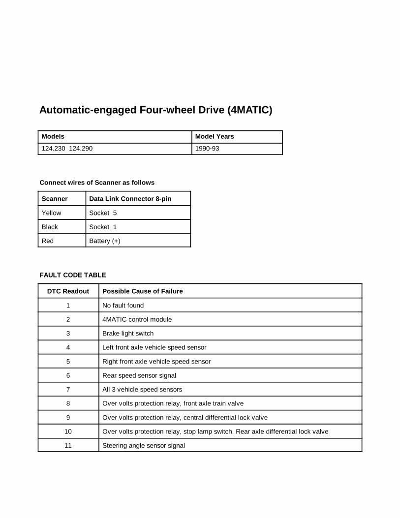
����1 Transmission Module CS1000 Code Scanner OB15-12
Copyright © 1998 Baum Tools Unlimited Inc. All rights reserved.Reproduction in whole or in part in any form or medium without express written permission of Baum Tools Unlimited Inc. is prohibited.
153
�����2 ��3�� ����
�����!���$��'!'�& ���#$*+��� #�,� -�����������!���$��'!'�& ���#$*+��� #�,� -�����������!���$��'!'�& ���#$*+��� #�,� -�����������!���$��'!'�& ���#$*+��� #�,� -������
���� 1
Models Model Years
124.230 124.290 1990-93
Connect wires of Scanner as f ollows
Scanner Data Link Connector 8-pin
Yellow Socket 5
Black Socket 1
Red Battery (+)
FAULT CODE TABLE
DTC Readout Possible Cause of Failure
1 No fault found
2 4MATIC control module
3 Brake light switch
4 Left front axle vehicle speed sensor
5 Right front axle vehicle speed sensor
6 Rear speed sensor signal
7 All 3 vehicle speed sensors
8 Over volts protection relay, front axle train valve
9 Over volts protection relay, central differential lock valve
10 Over volts protection relay, stop lamp switch, Rear axle differential lock valve
11 Steering angle sensor signal
Automatic-engaged Four-wheel Drive (4MATIC)
Automatic-engaged Four-wheel Drive (4MATIC)
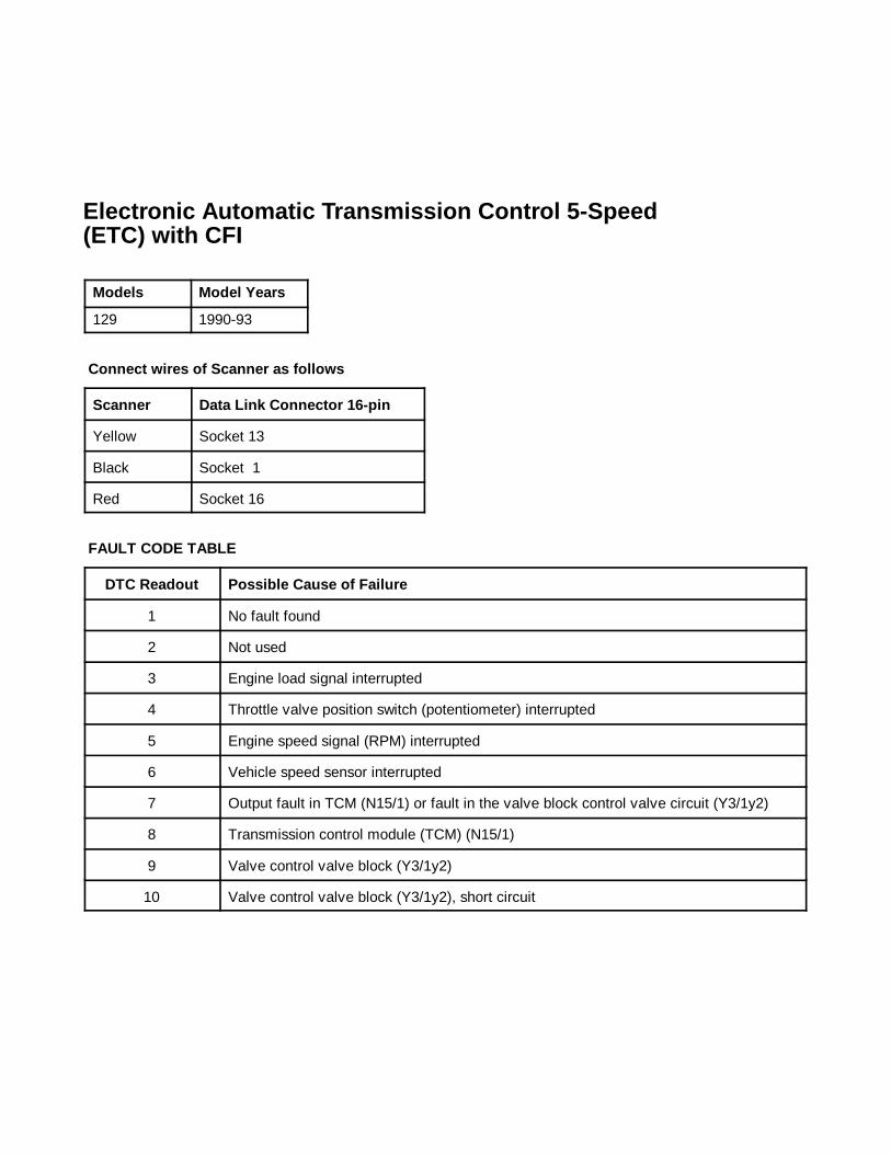
����1 Transmission Module CS1000 Code Scanner OB15-12
Copyright © 1998 Baum Tools Unlimited Inc. All rights reserved.Reproduction in whole or in part in any form or medium without express written permission of Baum Tools Unlimited Inc. is prohibited.
154
�����#���� �����!��� �#!��������� ����#�� 9$�"��&�����#���� �����!��� �#!��������� ����#�� 9$�"��&�����#���� �����!��� �#!��������� ����#�� 9$�"��&�����#���� �����!��� �#!��������� ����#�� 9$�"��&
���� *��+ ��� ���� *��+ ��� ���� *��+ ��� ���� *��+ ���
���� 1
Models Model Years
129 1990-93
Connect wires of Scanner as f ollows
Scanner Data Link Connector 16-pin
Yellow Socket 13
Black Socket 1
Red Socket 16
FAULT CODE TABLE
DTC Readout Possible Cause of Failure
1 No fault found
2 Not used
3 Engine load signal interrupted
4 Throttle valve position switch (potentiometer) interrupted
5 Engine speed signal (RPM) interrupted
6 Vehicle speed sensor interrupted
7 Output fault in TCM (N15/1) or fault in the valve block control valve circuit (Y3/1y2)
8 Transmission control module (TCM) (N15/1)
9 Valve control valve block (Y3/1y2)
10 Valve control valve block (Y3/1y2), short circuit
Electronic Automatic Transmission Control 5-Speed(ETC with CFI
Electronic Automatic Transmission Control 5-Speed (ETC) with CFI
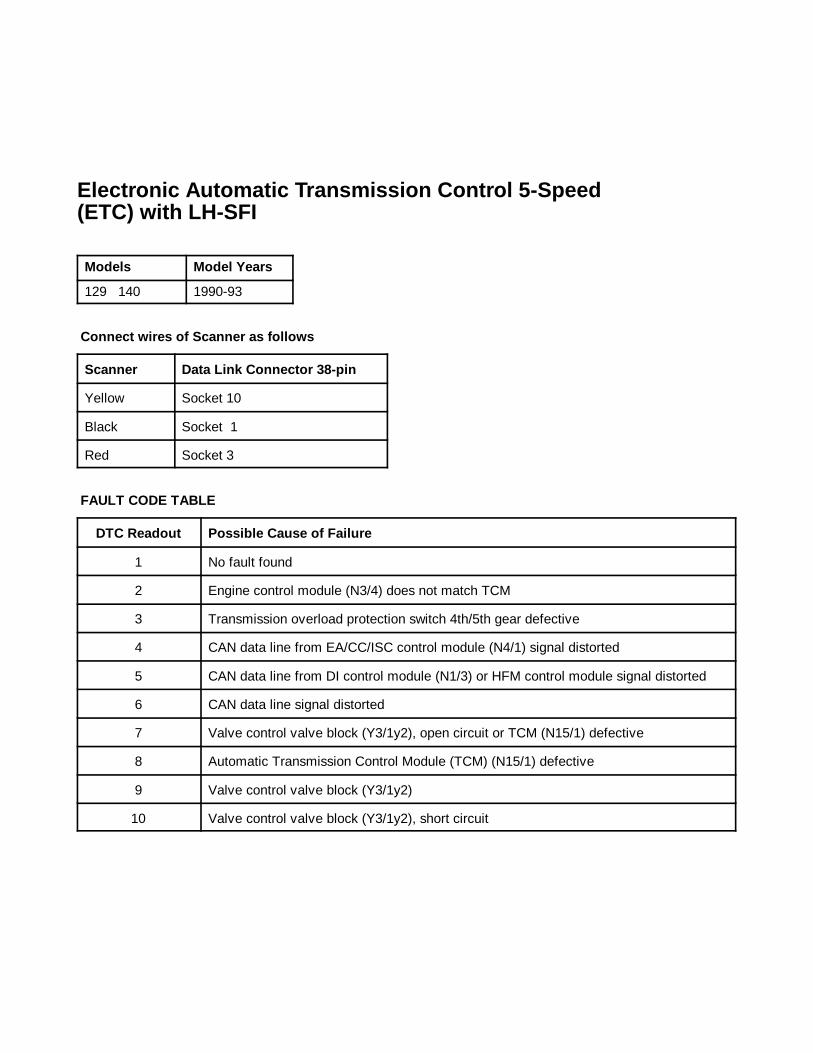
����1 Transmission Module CS1000 Code Scanner OB15-12
Copyright © 1998 Baum Tools Unlimited Inc. All rights reserved.Reproduction in whole or in part in any form or medium without express written permission of Baum Tools Unlimited Inc. is prohibited.
155
�����#���� �����!��� �#!��������� ����#�� 9$�"��&�����#���� �����!��� �#!��������� ����#�� 9$�"��&�����#���� �����!��� �#!��������� ����#�� 9$�"��&�����#���� �����!��� �#!��������� ����#�� 9$�"��&
���� *��+ ��$��� ���� *��+ ��$��� ���� *��+ ��$��� ���� *��+ ��$���
���� 1
Models Model Years
129 140 1990-93
Connect wires of Scanner as f ollows
Scanner Data Link Connector 38-pin
Yellow Socket 10
Black Socket 1
Red Socket 3
FAULT CODE TABLE
DTC Readout Possible Cause of Failure
1 No fault found
2 Engine control module (N3/4) does not match TCM
3 Transmission overload protection switch 4th/5th gear defective
4 CAN data line from EA/CC/ISC control module (N4/1) signal distorted
5 CAN data line from DI control module (N1/3) or HFM control module signal distorted
6 CAN data line signal distorted
7 Valve control valve block (Y3/1y2), open circuit or TCM (N15/1) defective
8 Automatic Transmission Control Module (TCM) (N15/1) defective
9 Valve control valve block (Y3/1y2)
10 Valve control valve block (Y3/1y2), short circuit
Electronic Automatic Transmission Control 5-Speed(ETC) with LH-SFI
Electronic Automatic Transmission Control 5-Speed (ETC) with LH-SFI
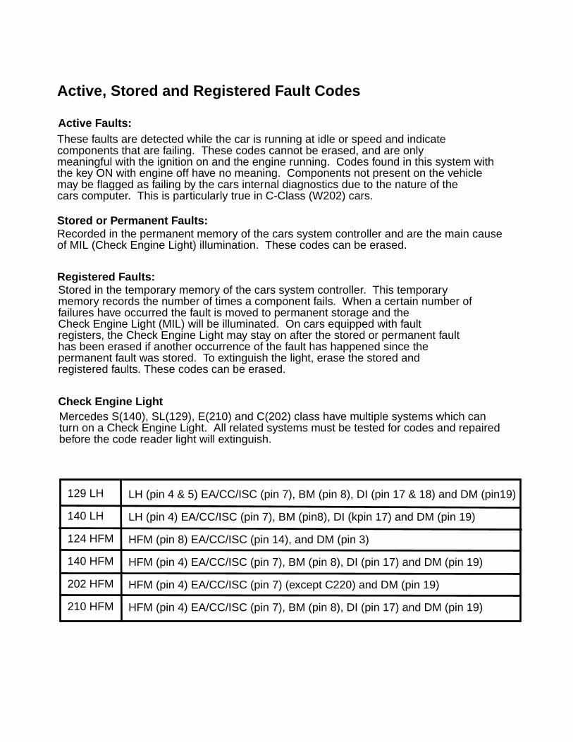
Mercedes Benz Code Scanner CS1000 OB15-11
2
Table of Contents
ANALOG FAULT CODES
ELECTRONIC DIESEL IDLE SPEED CONTROL (ELR)201.126 1989 . . . . . . . . . . . . . . . . . . . . . . . . . . 19
ELECTRONIC DIESEL SYSTEM (EDS)124.128 1990-91 . . . . . . . . . . . . . . . . . . . . . . . . 20126.134 126.135 1990-91 . . . . . . . . . . . . . . . . . . . . . . . . 20124.128 1992-93 . . . . . . . . . . . . . . . . . . . . . . . . 21140.134 1992-93 . . . . . . . . . . . . . . . . . . . . . . . . 21
CONTINUOUS FUEL INJECTION SYSTEM (CFI)124.026 124.030 124.050 124.090 1988-89 (California version only) . . . . . 22126.024 126.025 1988-89 (California version only) . . . . . 22201.028 (1988-93) 201.029 1988-89 (California version only) . . . . . 22107.048 1988-91 (California version only) . . . . . 22126.035 126.039 126.045 1988-91 (California version only) . . . . . 22124.026 124.030 124.090 124.230 124.290 1990-93 . . . . . . . . . . . . . . . . . . . . . . . . 23126.024 126.025 1990-93 . . . . . . . . . . . . . . . . . . . . . . . . 23201.029 1990-93 . . . . . . . . . . . . . . . . . . . . . . . . 23124.051 129.061 1990-93 . . . . . . . . . . . . . . . . . . . . . . . . 25129.066 1990-92 . . . . . . . . . . . . . . . . . . . . . . . . 25
CONTINUOUS FUEL INJECTION SYSTEM (MAS CONTROLLER)124.026 124.030 124.090 124.230 124.290 1990-92 . . . . . . . . . . . . . . . . . . . . . . . . 27129.066 1990-92 . . . . . . . . . . . . . . . . . . . . . . . . 27201.029 1990-92 . . . . . . . . . . . . . . . . . . . . . . . . 27
These faults are detected while the car is running at idle or speed. They indicatecomponents that are currently failing. These codes cannot be erased, and are onlymeaningful withthe ignition on and the engine running. Codes found in this system withthe Key On Engine Off have no meaning. Components not present on the vehicle may beflagged as failing by the cars internal diagnostics due to the generic nature of the carssoftware. This is particularly true in C-Class (W202) cars.
These faults are recorded in the permanent memory of the car’s system controller andare the main cause of MIL (Check Engine Light) illumination. These codes can be erased.
These fault codes are stored in the temporary memory of the of the cars system controller.This temporary memory records the number of times a component fails. When a certainnumber offailures have occurred the fault is moved to permanent storage and the CheckEngine Light (MIL) will be illuminated. On cars equipped with Fault Registers, theCheck Engine Light may stay on after the Stored or Permanent Fault has been erasedif anotheroccurrence of the fault has happened since the Permanent Fault was stored.To extinguish the light, erase the Stored and Registered faults. These codes can be erased.
Mercedes S(140), SL(129), E(210) and C(202) class have multiple systems which can turn onan Check Engine Light. All related systems must be tested for codes and repaired beforethe light will extinguish.
Details regarding Active, Stored and Registered Fault Codes
Active Faults:
Stored or Permanent Faults:
Registered Faults:
Check Engine Light Diagnosis
Active, Stored and Registered Fault Codes
129 LH
140 LH
124 HFM
140 HFM
202 HFM
210 HFM
LH (pin 4 & 5) EA/CC/ISC (pin 7), BM (pin 8), DI (pin 17 & 18) and DM (pin19)
LH (pin 4) EA/CC/ISC (pin 7), BM (pin8), DI (kpin 17) and DM (pin 19)
HFM (pin 8) EA/CC/ISC (pin 14), and DM (pin 3)
HFM (pin 4) EA/CC/ISC (pin 7), BM (pin 8), DI (pin 17) and DM (pin 19)
HFM (pin 4) EA/CC/ISC (pin 7) (except C220) and DM (pin 19)
HFM (pin 4) EA/CC/ISC (pin 7), BM (pin 8), DI (pin 17) and DM (pin 19)
These faults are detected while the car is running at idle or speed and indicate components that are failing. These codes cannot be erased, and are onlymeaningful with the ignition on and the engine running. Codes found in this system with the key ON with engine off have no meaning. Components not present on the vehiclemay be flagged as failing by the cars internal diagnostics due to the nature of thecars computer. This is particularly true in C-Class (W202) cars.
Active Faults:
Stored or Permanent Faults:Recorded in the permanent memory of the cars system controller and are the main causeof MIL (Check Engine Light) illumination. These codes can be erased.
Registered Faults:Stored in the temporary memory of the cars system controller. This temporarymemory records the number of times a component fails. When a certain number offailures have occurred the fault is moved to permanent storage and theCheck Engine Light (MIL) will be illuminated. On cars equipped with faultregisters, the Check Engine Light may stay on after the stored or permanent faulthas been erased if another occurrence of the fault has happened since thepermanent fault was stored. To extinguish the light, erase the stored andregistered faults. These codes can be erased.
Check Engine LightMercedes S(140), SL(129), E(210) and C(202) class have multiple systems which canturn on a Check Engine Light. All related systems must be tested for codes and repairedbefore the code reader light will extinguish.
Active, Stored and Registered Fault Codes
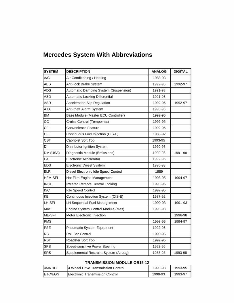
Mercedes Benz Code Scanner CS1000 OB15-11
18
Mercedes Benz System Type and Model Applications
SYSTEM DESCRIPTION ANALOG DIGITAL
A/C Air Conditioning / Heating 1988-93
ABS Anti-lock Brake System 1992-95 1992-97
ADS Automatic Damping System (Suspension) 1991-93
ASD Automatic Locking Differential 1991-93
ASR Acceleration Slip Regulation 1992-95 1992-97
ATA Anti-theft Alarm System 1990-95
BM Base Module (Master ECU Controller) 1992-95
CC Cruise Control (Tempomat) 1992-95
CF Convenience Feature 1992-95
CFI Continuous Fuel Injection (CIS-E) 1988-92
CST Cabriolet Soft Top 1993-95
DI Distributor Ignition System 1990-93
DM (USA) Diagnostic Module (Emissions) 1990-93 1991-98
EA Electronic Accelerator 1992-95
EDS Electronic Diesel System 1990-93
ELR Diesel Electronic Idle Speed Control 1989
HFM-SFI Hot Film Engine Management 1993-95 1994-97
IRCL Infrared Remote Central Locking 1990-95
ISC Idle Speed Control 1992-95
KE Continuous Injection System (CIS-E) 1987-92
LH-SFI LH Sequential Fuel Management 1990-93 1991-93
MAS Engine System Control Module (Mas) 1990-93
ME-SFI Motor Electronic Injection 1996-98
PMS 1993-95 1994-97
PSE Pneumatic System Equipment 1992-95
RB Roll Bar Control 1990-95
RST Roadster Soft Top 1992-95
SPS Speed-sensitive Power Steering 1992-95
SRS Supplemental Restraint System (Airbag) 1988-93 1993-98
TRANSMISSION MODULE OB15-124MATIC 4 Wheel Drive Transmission Control 1990-93 1993-95
ETC/EGS Electronic Transmission Control 1990-93 1993-97
Mercedes Benz System Type and Model ApplicationsMercedes System With Abbreviations
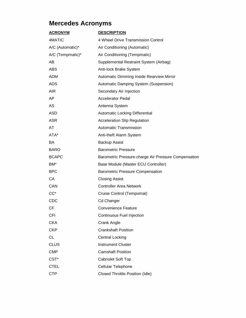
MERCEDES-BENZ ACRONYMS
Copyright © 1998 Baum Tools Unlimited Inc. All rights reserved.Reproduction in whole or in part in any form or medium without express written permission of Baum Tools Unlimited Inc. is prohibited.
160
ACRONYM DESCRIPTION
4MATIC 4 Wheel Drive Transmission Control
A/C (Automatic)* Air Conditioning (Automatic)
A/C (Tempmatic)* Air Conditioning (Tempmatic)
AB Supplemental Restraint System (Airbag)
ABS Anti-lock Brake System
ADM Automatic Dimming Inside Rearview Mirror
ADS Automatic Damping System (Suspension)
AIR Secondary Air Injection
AP Accelerator Pedal
AS Antenna System
ASD Automatic Locking Differential
ASR Acceleration Slip Regulation
AT Automatic Transmission
ATA* Anti-theft Alarm System
BA Backup Assist
BARO Barometric Pressure
BCAPC Barometric Pressure-charge Air Pressure Compensation
BM* Base Module (Master ECU Controller)
BPC Barometric Pressure Compensation
CA Closing Assist
CAN Controller Area Network
CC* Cruise Control (Tempomat)
CDC Cd Changer
CF Convenience Feature
CFI Continuous Fuel Injection
CKA Crank Angle
CKP Crankshaft Position
CL Central Locking
CLUS Instrument Cluster
CMP Camshaft Position
CST* Cabriolet Soft Top
CTEL Cellular Telephone
CTP Closed Throttle Position (Idle)
4MATIC 4 Wheel Drive Transmission Control 1990-93 and 1993-95ETC/EGS Electronic Transmission Control 1990-93 and 1993-95
Mercedes Acronyms
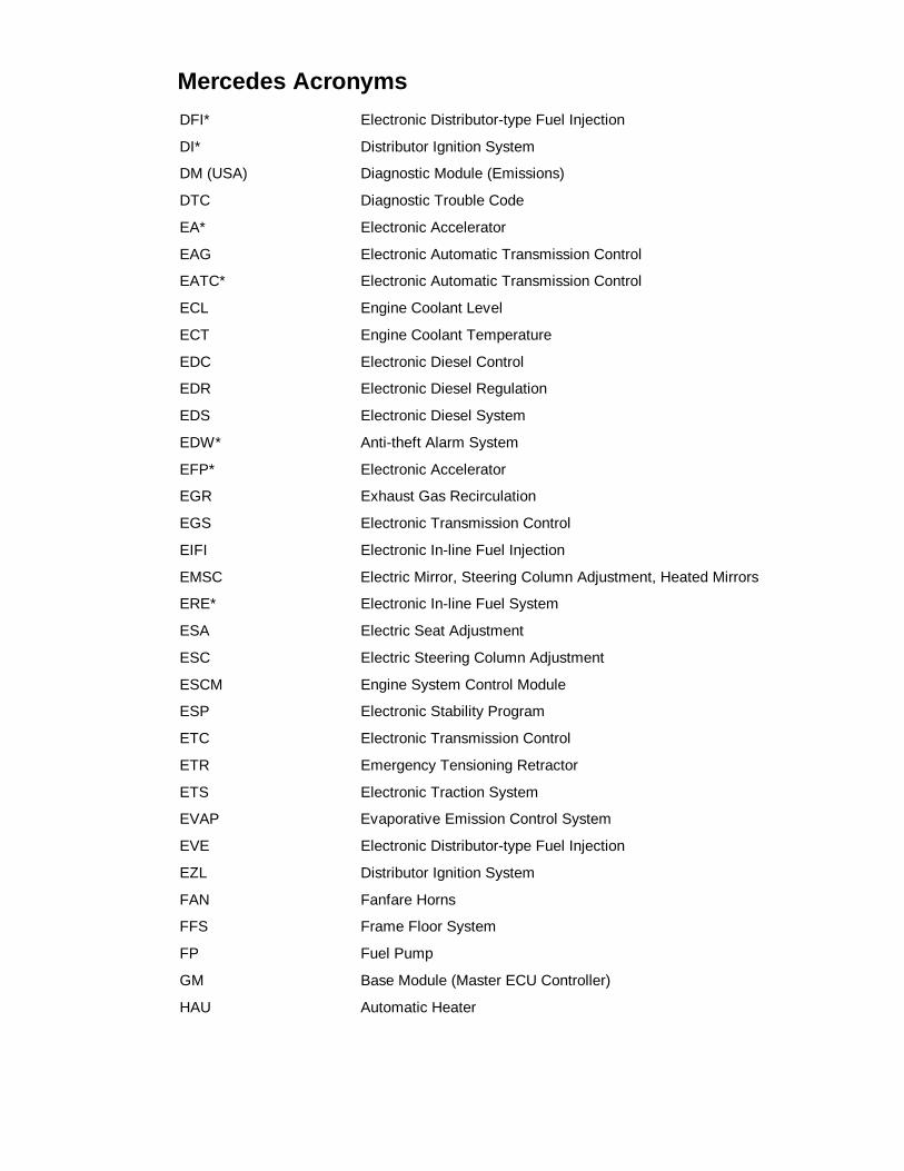
MERCEDES-BENZ ACRONYMS
Copyright © 1998 Baum Tools Unlimited Inc. All rights reserved.Reproduction in whole or in part in any form or medium without express written permission of Baum Tools Unlimited Inc. is prohibited.
161
DFI* Electronic Distributor-type Fuel Injection
DI* Distributor Ignition System
DM (USA) Diagnostic Module (Emissions)
DTC Diagnostic Trouble Code
EA* Electronic Accelerator
EAG Electronic Automatic Transmission Control
EATC* Electronic Automatic Transmission Control
ECL Engine Coolant Level
ECT Engine Coolant Temperature
EDC Electronic Diesel Control
EDR Electronic Diesel Regulation
EDS Electronic Diesel System
EDW* Anti-theft Alarm System
EFP* Electronic Accelerator
EGR Exhaust Gas Recirculation
EGS Electronic Transmission Control
EIFI Electronic In-line Fuel Injection
EMSC Electric Mirror, Steering Column Adjustment, Heated Mirrors
ERE* Electronic In-line Fuel System
ESA Electric Seat Adjustment
ESC Electric Steering Column Adjustment
ESCM Engine System Control Module
ESP Electronic Stability Program
ETC Electronic Transmission Control
ETR Emergency Tensioning Retractor
ETS Electronic Traction System
EVAP Evaporative Emission Control System
EVE Electronic Distributor-type Fuel Injection
EZL Distributor Ignition System
FAN Fanfare Horns
FFS Frame Floor System
FP Fuel Pump
GM Base Module (Master ECU Controller)
HAU Automatic Heater
Mercedes Acronyms
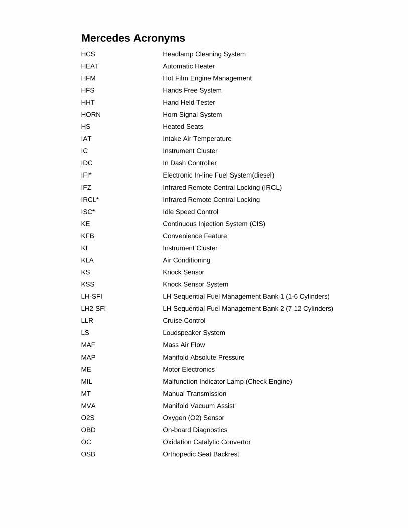
MERCEDES-BENZ ACRONYMS
Copyright © 1998 Baum Tools Unlimited Inc. All rights reserved.Reproduction in whole or in part in any form or medium without express written permission of Baum Tools Unlimited Inc. is prohibited.
162
HCS Headlamp Cleaning System
HEAT Automatic Heater
HFM Hot Film Engine Management
HFS Hands Free System
HHT Hand Held Tester
HORN Horn Signal System
HS Heated Seats
IAT Intake Air Temperature
IC Instrument Cluster
IDC In Dash Controller
IFI* Electronic In-line Fuel System(diesel)
IFZ Infrared Remote Central Locking (IRCL)
IRCL* Infrared Remote Central Locking
ISC* Idle Speed Control
KE Continuous Injection System (CIS)
KFB Convenience Feature
KI Instrument Cluster
KLA Air Conditioning
KS Knock Sensor
KSS Knock Sensor System
LH-SFI LH Sequential Fuel Management Bank 1 (1-6 Cylinders)
LH2-SFI LH Sequential Fuel Management Bank 2 (7-12 Cylinders)
LLR Cruise Control
LS Loudspeaker System
MAF Mass Air Flow
MAP Manifold Absolute Pressure
ME Motor Electronics
MIL Malfunction Indicator Lamp (Check Engine)
MT Manual Transmission
MVA Manifold Vacuum Assist
O2S Oxygen (O2) Sensor
OBD On-board Diagnostics
OC Oxidation Catalytic Convertor
OSB Orthopedic Seat Backrest
Mercedes Acronyms
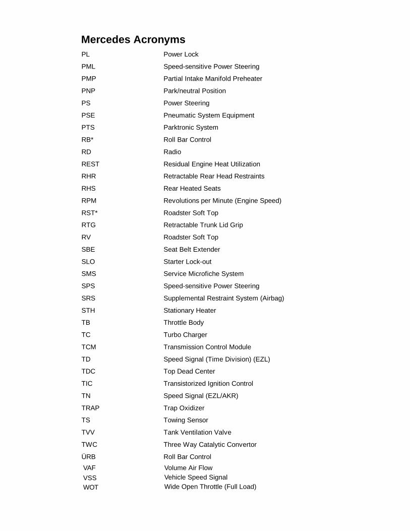
MERCEDES-BENZ ACRONYMS
Copyright © 1998 Baum Tools Unlimited Inc. All rights reserved.Reproduction in whole or in part in any form or medium without express written permission of Baum Tools Unlimited Inc. is prohibited.
163
PL Power Lock
PML Speed-sensitive Power Steering
PMP Partial Intake Manifold Preheater
PNP Park/neutral Position
PS Power Steering
PSE Pneumatic System Equipment
PTS Parktronic System
RB* Roll Bar Control
RD Radio
REST Residual Engine Heat Utilization
RHR Retractable Rear Head Restraints
RHS Rear Heated Seats
RPM Revolutions per Minute (Engine Speed)
RST* Roadster Soft Top
RTG Retractable Trunk Lid Grip
RV Roadster Soft Top
SBE Seat Belt Extender
SLO Starter Lock-out
SMS Service Microfiche System
SPS Speed-sensitive Power Steering
SRS Supplemental Restraint System (Airbag)
STH Stationary Heater
TB Throttle Body
TC Turbo Charger
TCM Transmission Control Module
TD Speed Signal (Time Division) (EZL)
TDC Top Dead Center
TIC Transistorized Ignition Control
TN Speed Signal (EZL/AKR)
TRAP Trap Oxidizer
TS Towing Sensor
TVV Tank Ventilation Valve
TWC Three Way Catalytic Convertor
ÜRB Roll Bar Control
VAF
VSSWOT
Volume Air FlowVehicle Speed SignalWide Open Throttle (Full Load)
Mercedes Acronyms
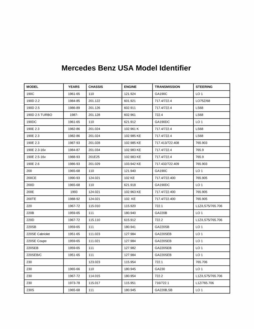
MERCEDES-BENZ ACRONYMS
164Baum Tools Unlimited Inc. Toll Free 1-800-848-6657
VAF Volume Air Flow
VSS Vehicle Speed Signal
WOT Wide Open Throttle (Full Load)
* USA Acronym only.
�������� �� � �� ����� ����������������� �� � �� ����� ����������������� �� � �� ����� ����������������� �� � �� ����� ���������
MODEL YEARS CHASSIS ENGINE TRANSMISSION STEERING
190C 1961-65 110 121.924 GA190C LO 1
190D 2.2 1984-85 201.122 601.921 717.4/722.4 LO75Z/68
190D 2.5 1986-89 201.126 602.911 717.4/722.4 LS68
190D 2.5 TURBO 1987- 201.128 602.961 722.4 LS68
190DC 1961-65 110 621.912 GA190DC LO 1
190E 2.3 1982-86 201.024 102.961 K 717.4/722.4 LS68
190E 2.3 1982-86 201.024 102.985 KE 717.4/722.4 LS68
190E 2.3 1987-93 201.028 102.985 KE 717.413/722.408 765.903
190E 2.3-16v 1984-87 201.034 102.983 KE 717.4/722.4 765.9
190E 2.5-16v 1988-93 201E25 102.983 KE 717.4/722.4 765.9
190E 2.6 1986-93 201.029 103.942 KE 717.432/722.409 765.903
200 1965-68 110 121.940 GA190C LO 1
200CE 1990-93 124.021 102 KE 717.4/722.400 765.905
200D 1965-68 110 621.918 GA190DC LO 1
200E 1993 124.021 102.963 KE 717.4/722.400 765.905
200TE 1988-92 124.021 102. KE 717.4/722.400 765.905
220 1967-72 115.010 115.920 722.1 L1Z/LS75/765.706
220B 1959-65 111 180.940 GA220B LO 1
220D 1967-72 115.110 615.912 722.2 L1Z/LS75/765.706
220SB 1959-65 111 180.941 GA220SB LO 1
220SE Cabriolet 1951-65 111.023 127.984 GA220SEB LO 1
220SE Coupe 1959-65 111.021 127.984 GA220SEB LO 1
220SEB 1959-65 111 127.982 GA220SEB LO 1
220SEB/C 1951-65 111 127.984 GA220SEB LO 1
230 123.023 115.954 722.1 765.706
230 1965-66 110 180.945 GA230 LO 1
230 1967-72 114.015 180.954 722.2 L1Z/LS75/765.706
230 1973-78 115.017 115.951 716/722.1 L1Z/765.706
230S 1965-68 111 180.945 GA220B,SB LO 1
Mercedes Benz USA Model Identifier
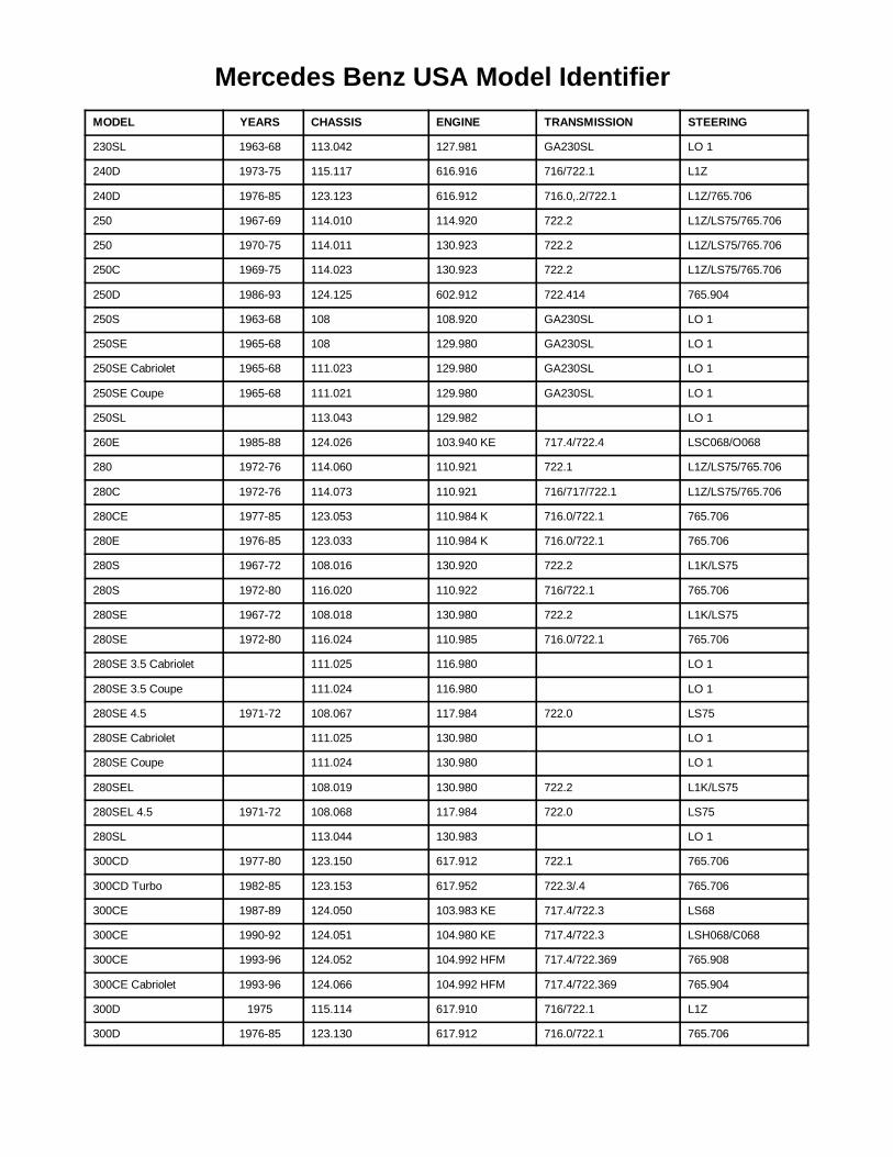
MERCEDES-BENZ ACRONYMSMODEL YEARS CHASSIS ENGINE TRANSMISSION STEERING
165Baum Tools Unlimited Inc. Toll Free 1-800-848-6657
230SL 1963-68 113.042 127.981 GA230SL LO 1
240D 1973-75 115.117 616.916 716/722.1 L1Z
240D 1976-85 123.123 616.912 716.0,.2/722.1 L1Z/765.706
250 1967-69 114.010 114.920 722.2 L1Z/LS75/765.706
250 1970-75 114.011 130.923 722.2 L1Z/LS75/765.706
250C 1969-75 114.023 130.923 722.2 L1Z/LS75/765.706
250D 1986-93 124.125 602.912 722.414 765.904
250S 1963-68 108 108.920 GA230SL LO 1
250SE 1965-68 108 129.980 GA230SL LO 1
250SE Cabriolet 1965-68 111.023 129.980 GA230SL LO 1
250SE Coupe 1965-68 111.021 129.980 GA230SL LO 1
250SL 113.043 129.982 LO 1
260E 1985-88 124.026 103.940 KE 717.4/722.4 LSC068/O068
280 1972-76 114.060 110.921 722.1 L1Z/LS75/765.706
280C 1972-76 114.073 110.921 716/717/722.1 L1Z/LS75/765.706
280CE 1977-85 123.053 110.984 K 716.0/722.1 765.706
280E 1976-85 123.033 110.984 K 716.0/722.1 765.706
280S 1967-72 108.016 130.920 722.2 L1K/LS75
280S 1972-80 116.020 110.922 716/722.1 765.706
280SE 1967-72 108.018 130.980 722.2 L1K/LS75
280SE 1972-80 116.024 110.985 716.0/722.1 765.706
280SE 3.5 Cabriolet 111.025 116.980 LO 1
280SE 3.5 Coupe 111.024 116.980 LO 1
280SE 4.5 1971-72 108.067 117.984 722.0 LS75
280SE Cabriolet 111.025 130.980 LO 1
280SE Coupe 111.024 130.980 LO 1
280SEL 108.019 130.980 722.2 L1K/LS75
280SEL 4.5 1971-72 108.068 117.984 722.0 LS75
280SL 113.044 130.983 LO 1
300CD 1977-80 123.150 617.912 722.1 765.706
300CD Turbo 1982-85 123.153 617.952 722.3/.4 765.706
300CE 1987-89 124.050 103.983 KE 717.4/722.3 LS68
300CE 1990-92 124.051 104.980 KE 717.4/722.3 LSH068/C068
300CE 1993-96 124.052 104.992 HFM 717.4/722.369 765.908
300CE Cabriolet 1993-96 124.066 104.992 HFM 717.4/722.369 765.904
300D 1975 115.114 617.910 716/722.1 L1Z
300D 1976-85 123.130 617.912 716.0/722.1 765.706
Mercedes Benz USA Model Identifier
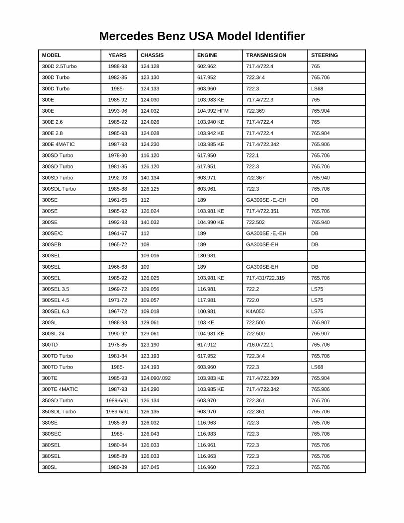
MERCEDES-BENZ ACRONYMSMODEL YEARS CHASSIS ENGINE TRANSMISSION STEERING
166Baum Tools Unlimited Inc. Toll Free 1-800-848-6657
300D 2.5Turbo 1988-93 124.128 602.962 717.4/722.4 765
300D Turbo 1982-85 123.130 617.952 722.3/.4 765.706
300D Turbo 1985- 124.133 603.960 722.3 LS68
300E 1985-92 124.030 103.983 KE 717.4/722.3 765
300E 1993-96 124.032 104.992 HFM 722.369 765.904
300E 2.6 1985-92 124.026 103.940 KE 717.4/722.4 765
300E 2.8 1985-93 124.028 103.942 KE 717.4/722.4 765.904
300E 4MATIC 1987-93 124.230 103.985 KE 717.4/722.342 765.906
300SD Turbo 1978-80 116.120 617.950 722.1 765.706
300SD Turbo 1981-85 126.120 617.951 722.3 765.706
300SD Turbo 1992-93 140.134 603.971 722.367 765.940
300SDL Turbo 1985-88 126.125 603.961 722.3 765.706
300SE 1961-65 112 189 GA300SE,-E,-EH DB
300SE 1985-92 126.024 103.981 KE 717.4/722.351 765.706
300SE 1992-93 140.032 104.990 KE 722.502 765.940
300SE/C 1961-67 112 189 GA300SE,-E,-EH DB
300SEB 1965-72 108 189 GA300SE-EH DB
300SEL 109.016 130.981
300SEL 1966-68 109 189 GA300SE-EH DB
300SEL 1985-92 126.025 103.981 KE 717.431/722.319 765.706
300SEL 3.5 1969-72 109.056 116.981 722.2 LS75
300SEL 4.5 1971-72 109.057 117.981 722.0 LS75
300SEL 6.3 1967-72 109.018 100.981 K4A050 LS75
300SL 1988-93 129.061 103 KE 722.500 765.907
300SL-24 1990-92 129.061 104.981 KE 722.500 765.907
300TD 1978-85 123.190 617.912 716.0/722.1 765.706
300TD Turbo 1981-84 123.193 617.952 722.3/.4 765.706
300TD Turbo 1985- 124.193 603.960 722.3 LS68
300TE 1985-93 124.090/.092 103.983 KE 717.4/722.369 765.904
300TE 4MATIC 1987-93 124.290 103.985 KE 717.4/722.342 765.906
350SD Turbo 1989-6/91 126.134 603.970 722.361 765.706
350SDL Turbo 1989-6/91 126.135 603.970 722.361 765.706
380SE 1985-89 126.032 116.963 722.3 765.706
380SEC 1985- 126.043 116.983 722.3 765.706
380SEL 1980-84 126.033 116.961 722.3 765.706
380SEL 1985-89 126.033 116.963 722.3 765.706
380SL 1980-89 107.045 116.960 722.3 765.706
Mercedes Benz USA Model Identifier
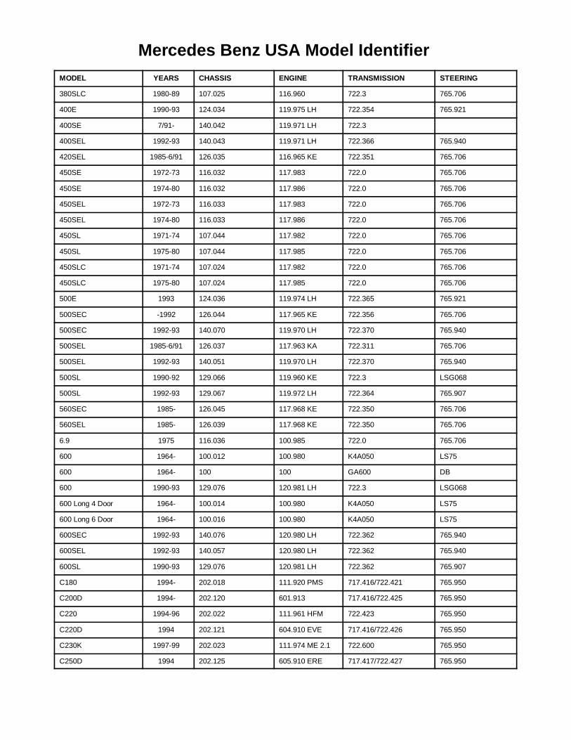
MERCEDES-BENZ ACRONYMSMODEL YEARS CHASSIS ENGINE TRANSMISSION STEERING
167Baum Tools Unlimited Inc. Toll Free 1-800-848-6657
380SLC 1980-89 107.025 116.960 722.3 765.706
400E 1990-93 124.034 119.975 LH 722.354 765.921
400SE 7/91- 140.042 119.971 LH 722.3
400SEL 1992-93 140.043 119.971 LH 722.366 765.940
420SEL 1985-6/91 126.035 116.965 KE 722.351 765.706
450SE 1972-73 116.032 117.983 722.0 765.706
450SE 1974-80 116.032 117.986 722.0 765.706
450SEL 1972-73 116.033 117.983 722.0 765.706
450SEL 1974-80 116.033 117.986 722.0 765.706
450SL 1971-74 107.044 117.982 722.0 765.706
450SL 1975-80 107.044 117.985 722.0 765.706
450SLC 1971-74 107.024 117.982 722.0 765.706
450SLC 1975-80 107.024 117.985 722.0 765.706
500E 1993 124.036 119.974 LH 722.365 765.921
500SEC -1992 126.044 117.965 KE 722.356 765.706
500SEC 1992-93 140.070 119.970 LH 722.370 765.940
500SEL 1985-6/91 126.037 117.963 KA 722.311 765.706
500SEL 1992-93 140.051 119.970 LH 722.370 765.940
500SL 1990-92 129.066 119.960 KE 722.3 LSG068
500SL 1992-93 129.067 119.972 LH 722.364 765.907
560SEC 1985- 126.045 117.968 KE 722.350 765.706
560SEL 1985- 126.039 117.968 KE 722.350 765.706
6.9 1975 116.036 100.985 722.0 765.706
600 1964- 100.012 100.980 K4A050 LS75
600 1964- 100 100 GA600 DB
600 1990-93 129.076 120.981 LH 722.3 LSG068
600 Long 4 Door 1964- 100.014 100.980 K4A050 LS75
600 Long 6 Door 1964- 100.016 100.980 K4A050 LS75
600SEC 1992-93 140.076 120.980 LH 722.362 765.940
600SEL 1992-93 140.057 120.980 LH 722.362 765.940
600SL 1990-93 129.076 120.981 LH 722.362 765.907
C180 1994- 202.018 111.920 PMS 717.416/722.421 765.950
C200D 1994- 202.120 601.913 717.416/722.425 765.950
C220 1994-96 202.022 111.961 HFM 722.423 765.950
C220D 1994 202.121 604.910 EVE 717.416/722.426 765.950
C230K 1997-99 202.023 111.974 ME 2.1 722.600 765.950
C250D 1994 202.125 605.910 ERE 717.417/722.427 765.950
Mercedes Benz USA Model Identifier
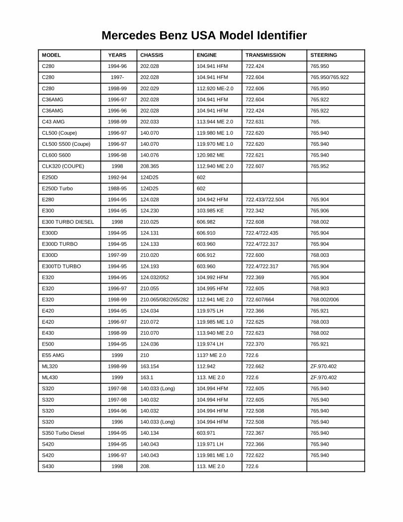
MERCEDES-BENZ ACRONYMSMODEL YEARS CHASSIS ENGINE TRANSMISSION STEERING
168Baum Tools Unlimited Inc. Toll Free 1-800-848-6657
C280 1994-96 202.028 104.941 HFM 722.424 765.950
C280 1997- 202.028 104.941 HFM 722.604 765.950/765.922
C280 1998-99 202.029 112.920 ME-2.0 722.606 765.950
C36AMG 1996-97 202.028 104.941 HFM 722.604 765.922
C36AMG 1996-96 202.028 104.941 HFM 722.424 765.922
C43 AMG 1998-99 202.033 113.944 ME 2.0 722.631 765.
CL500 (Coupe) 1996-97 140.070 119.980 ME 1.0 722.620 765.940
CL500 S500 (Coupe) 1996-97 140.070 119.970 ME 1.0 722.620 765.940
CL600 S600 1996-98 140.076 120.982 ME 722.621 765.940
CLK320 (COUPE) 1998 208.365 112.940 ME 2.0 722.607 765.952
E250D 1992-94 124D25 602
E250D Turbo 1988-95 124D25 602
E280 1994-95 124.028 104.942 HFM 722.433/722.504 765.904
E300 1994-95 124.230 103.985 KE 722.342 765.906
E300 TURBO DIESEL 1998 210.025 606.982 722.608 768.002
E300D 1994-95 124.131 606.910 722.4/722.435 765.904
E300D TURBO 1994-95 124.133 603.960 722.4/722.317 765.904
E300D 1997-99 210.020 606.912 722.600 768.003
E300TD TURBO 1994-95 124.193 603.960 722.4/722.317 765.904
E320 1994-95 124.032/052 104.992 HFM 722.369 765.904
E320 1996-97 210.055 104.995 HFM 722.605 768.903
E320 1998-99 210.065/082/265/282 112.941 ME 2.0 722.607/664 768.002/006
E420 1994-95 124.034 119.975 LH 722.366 765.921
E420 1996-97 210.072 119.985 ME 1.0 722.625 768.003
E430 1998-99 210.070 113.940 ME 2.0 722.623 768.002
E500 1994-95 124.036 119.974 LH 722.370 765.921
E55 AMG 1999 210 113? ME 2.0 722.6
ML320 1998-99 163.154 112.942 722.662 ZF.970.402
ML430 1999 163.1 113. ME 2.0 722.6 ZF.970.402
S320 1997-98 140.033 (Long) 104.994 HFM 722.605 765.940
S320 1997-98 140.032 104.994 HFM 722.605 765.940
S320 1994-96 140.032 104.994 HFM 722.508 765.940
S320 1996 140.033 (Long) 104.994 HFM 722.508 765.940
S350 Turbo Diesel 1994-95 140.134 603.971 722.367 765.940
S420 1994-95 140.043 119.971 LH 722.366 765.940
S420 1996-97 140.043 119.981 ME 1.0 722.622 765.940
S430 1998 208. 113. ME 2.0 722.6
Mercedes Benz USA Model Identifier
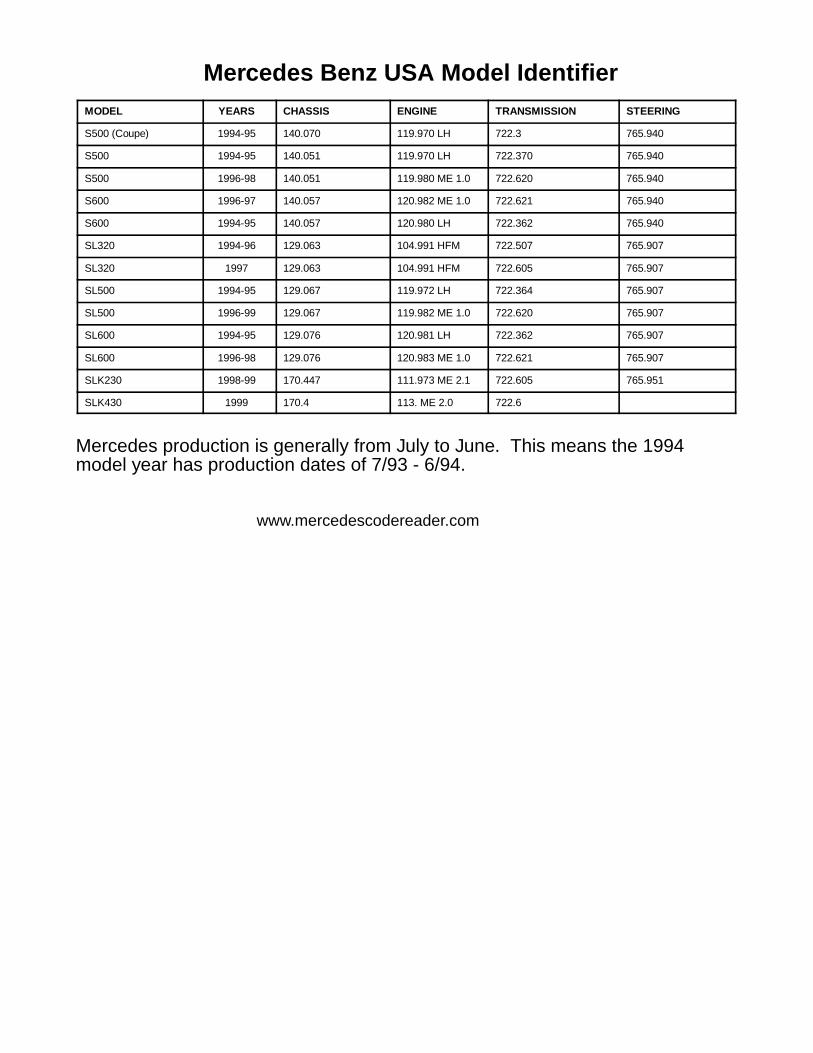
MERCEDES-BENZ ACRONYMSMODEL YEARS CHASSIS ENGINE TRANSMISSION STEERING
169
S500 (Coupe) 1994-95 140.070 119.970 LH 722.3 765.940
S500 1994-95 140.051 119.970 LH 722.370 765.940
S500 1996-98 140.051 119.980 ME 1.0 722.620 765.940
S600 1996-97 140.057 120.982 ME 1.0 722.621 765.940
S600 1994-95 140.057 120.980 LH 722.362 765.940
SL320 1994-96 129.063 104.991 HFM 722.507 765.907
SL320 1997 129.063 104.991 HFM 722.605 765.907
SL500 1994-95 129.067 119.972 LH 722.364 765.907
SL500 1996-99 129.067 119.982 ME 1.0 722.620 765.907
SL600 1994-95 129.076 120.981 LH 722.362 765.907
SL600 1996-98 129.076 120.983 ME 1.0 722.621 765.907
SLK230 1998-99 170.447 111.973 ME 2.1 722.605 765.951
SLK430 1999 170.4 113. ME 2.0 722.6
Mercedes production is generally from July to June. This means that the 1994 model year has production dates
7/93-6/94.Mercedes production is generally from July to June. This means the 1994model year has production dates of 7/93 - 6/94.
Mercedes Benz USA Model Identifier
www.mercedescodereader.com