mercedes-benz daimler ag adaption module as vehicle ...avtotir.ucoz.ru/adm3-manual-rev901.pdf ·...
TRANSCRIPT

Mercedes-Benz Daimler AG
Adaption Module as Vehicle Control ADM3
Control Unit Operating Manual
Revision 9.01

Version History
2 / 207 ADM3 operating manual rev. 9.01
Version History
Date Revision Changes
2009-12-18 9.01
• Chapter 9.1. (Fault codes diagnosis version 209) and 9.2. (Fault codes listed by K-line code): New fault codes SPN 1136 FMI 0 and FMI 1 (Engine ECU Temperature too High / too Low) from PLD/MR2 added, FMI values 5 and 6 for path 33 (Output Relay 1) changed to 3 and 4 respectively
• Chapter 9.1. (Fault codes diagnosis version 209) and 9.2. (Fault codes listed by K-line code): The following changes only apply to engines which are equipped with a SCR system Proprietary Fault Code SPN 520229 FMI 7 changed to standard compliant SPN 4794 FMI 14, SPN 520261 FMI 12 changed to SPN 4332 FMI 12, FMI values for SPNs 1231, 3220 and 171 from PLD/MR2 changed from 8 to 9, FMI values for SPN 520262 from PLD/MR2 changed from 12 to 14 (Mannheim-Function and Wörth-Function now have the same FMI),
• Chapter 11.6.3. (DM1 – Diagnostic Message 1, Active Diagnostic Trouble Codes (send)): Repetition rate of J1939 CAN message DM1 adapted to sending also when there are no active faults
2009-12-18 9.00
• Chapters 4.1.1. and 4.2.1. (Group 01 – CAN Configuration): Parameters 01/17 (J1939 Timeout Detection) and 01/18 (SPN Conversion Method) added
• Chapters 4.1.3. (Group 03 – Common Limiters): Maximum value of parameter 03/03 (Maximum Road Speed (legal)) changed
• Chapters 4.1.13. and 4.2.13. (Group 13 – Inputs): Description of parameter value 0 of parameter 13/13 changed to disabled or stalk switch, Parameter values of parameter 13/37 (Input DSF2) extended by 2 (Enable TSC1 from SA3), 3 (Quit Signal for CC with Stalk Switch) and 4 (Power Rating with DSF2), default value changed from 1 to 0
• Chapters 4.1.18. and 4.2.18. (Group 18 – Engine Protection): Parameter 18/13 (Oil Level Lamp Configuration) added
• Chapters 4.1.20. and 4.2.20. (Group 20 – Remote Accelerator Pedal): New parameter 20/07 (HFG Diagnostics Only With Active Pin “FG-Wahl”)
• Chapter 7.1.2.2. (Cruise control when using a stalk switch) added
• Chapter 7.5.6. (Engine brake operation with a stalk switch) added • Chapter 7.6.6. (Oil level indicator lamp):
The usage of the oil level lamp is extended with the help of the new parameter 18/13 (Oil Level Lamp Configuration) for indicating low oil level and engine overspeed as well
• Chapter 7.12.8. (Securing of TSC1 message from third source) added • Chapter 7.12.9. (Power Rating with DSF2) added
• Chapter 7.13.2. (J1939 Diagnosis) added • Chapter 8.1. (Analog Values):
Analog Value “Ambient Air Temperature” added
• Chapter 9. (Fault codes): Description of fault locations brought into accordance with newly integrated errors of J1939-signals
• Chapter 9.1. (Fault codes diagnosis version 209): Errors broadcasted from the PLD/MR2 newly included because of possibility to be read out via J1939
• Chapter 9.1. (Fault codes diagnosis version 209) and 9.2. (Fault codes listed by K-line code): Change of diagnosis version from 207 to 209, Errors for J1939-signals (FMI 9: Signal Not Available, FMI 19: Received Network Data In Error) as well as messages (FMI 9: Abnormal Update Rate) added, Failure detection of Decompression Valve MBR_KD (ADM3 path 0) and Intake Air Heater (now residing on ADM3 path 40, SPN 729) separated, SPN of path 0 (Decompression Valve MBR_KD) changed to 1072, SPN of path 46 (Exhaust Brake Valve MBR_BK) changed to 1074, Fault codes 11814 (SPN 599, FMI 14), 11914 (SPN 601, FMI 14), 12002 (SPN 609, FMI 2), 19214 (SPN 1633, FMI 14) added
• Chapter 9.2. (Fault codes listed by K-line code) added for reverse search of failure codes • Chapters 11.4.1. (Miscellaneous messages) and 11.5.3. (RESET – Reset):
Receive message RESET for deleting of trip data over J1939 added
• Chapters 11.4.2 (Diagnostic messages), 11.6.1. (Diagnostic Message 13 – Stop Start Broadcast), 11.6.5. (Diagnostic Message 3 – Diagnostic Data Clear/Reset Of Previously Active DTCs), 11.6.6. (Diagnostic Message 4 – Freeze Frame Parameters) and 11.6.7. (Diagnostic Message 11 – Diagnostic Data Clear/Reset For Active DTCs) added

Version History
ADM3 operating manual rev. 9.01 3 / 207
2009-12-16 7.03j
• Chapter 3.2. (Wiring diagram of ADM3) added • Chapter 3.3.3. (12 pin Connector):
Description of pin 12/07 corrected to configurable input DSF2
• Chapters 3.3.2. (18 pin Connector) and 3.3.3. (12 pin Connector) and 3.3.4. (15 pin Connector): Parameter numbers noted for relays 1 to 4, DSF0, DSF1, DSF2, IWA
• Chapter 4.1. (List of Parameters): Correction of default values of parameters 02/05, 11/10, 14/01, 14/10, 14/21, 16/01, 19/09, 19/10, 19/13 and 19/14
• Chapter 4.1. (List of Parameters): Completion of units in parameter tables
• Chapter 4.1. (List of Parameters): Correction of maximum values of parameters 13/02, 13/07 and 14/74
• Chapter 4.1.5 (Group 05 – Limiters LIM0 and LIM1) and 4.1.6. (Group 06 – Limiters AC/LIM2): Minimum values of parameters 05/04, 05/08 and 06/06 changed to -2000Nm
• Chapter 4.1.22 (Group 22 – TSC1 Limiter Governor (N max)): Maximum value of parameter 22/01 changed to 4, Parameters 22/01 to 22/04 are visible now
• Chapter 7.12.7. (TSC1 Speed Control and Speed Limitation) added • Chapter 8.2. (Binary Values):
Binary value 11/2 changed to DSF2 Status
• Chapter 9.1. (Fault codes diagnosis version 207): Fault codes 10202, 10900, 12312, 15002 deleted because they are not supported by software
• All chapters: Uniform notation PLD/MR2 for engine controller
2009-04-20 7.03i
• Chapter 4.1.22. (Group 22 – TSC1 Limiter Governor (n max)): Default value of parameter 22/20 corrected to 0
• Chapter 11.5.25. (EBC2 – Wheel Speed Information): Signal names of Bytes 5 to 8 corrected
2009-02-10 7.03h
• Chapter 7.3.1. (PWM accelerator pedal): Correction of abstract “Various PWM accelerator pedal types”
• Chapter 7.5. (Engine Brake (Retarder)): Parameter 02/13 corrected to 10/13 (Engine Brake Configuration)
• Chapter 7.5.3.4. (Exhaust flap and decompression valve at one valve): X 15/10 changed to X 15/06 in Fig. 12
• Chapter 7.5.3. (Engine brake configuration): Reference to PLD parameters 06/01 and 06/02 extended by reference to MR2 parameters depending on diagnosis version in subchapters 7.5.3.1., 7.5.3.2., 7.5.3.3., 7.5.3.4., 7.5.3.5.1., 7.5.3.5.2. and 7.5.3.5.3., “analog valve” changed to “proportional valve”
2009-01-14 7.03g
• Chapters 3.2.1. (21 pin Connector): Description of pin 21/16 corrected
• Chapters 3.2.2. (18 pin Connector), 4.1.14. and 4.2.14. (Relay 3/4, AdBlue, NOx, misc.): Parameter value 11 of parameter 14/10 (Configuration Relay 4 (IWK4)) changed to “Reserved”
• Chapters 4.1.25 and 4.2.25 (XTempomat) and 4.1.28 and 4.2.28 (Real TimeClock) added • Chapters 4.1.2. and 4.2.2. (Group 2 – Vehicle Parameters I):
Parameter value 2 of parameter 02/09 described more precisely
• Chapter 4.1.11. (Group 11 – Accelerator Pedal): Default value of parameter 11/08 (PWM Pedal Kickdown Switch Off Threshold) changed to 11%
• Chapters 4.1.19. and 4.2.19. (Group 19 – Fan): Description of parameters 13 (DSF0 Fan) and 14 (DSF1 Fan) added
• Chapters 4.1.22 (Group 22 – TSC1 Limiter Governor (n max)): Description of not visible parameters 1-8 and 16-18 eliminated
• Chapter 7.3.1. (PWM accelerator pedal): Description of parameter issues caused by new PWM pedal type added
• Chapters 7.12.2. (Conventional Retarder) and 7.12.3. (Automatic Fan): Correction of parameter numbering of parameters in group 19 (Fan) and 13 (Inputs)
• Chapter 7.12.3. (Automatic Fan): Correction of parameter numbering in Fig. 18
• Release of an updated version 6.06d of this manual containing these and other corrections from the release 7 manuals, for detailed description of the changes compare manual 6.06d
2008-07-16 7.03f
• Chapter 4.1.11. (Group 11 – Accelerator Pedal): Default value of parameter 11/09 corrected to 0
• Release of an updated version 6.06c of this manual containing these and other corrections from the release 7 manuals, for detailed description of the changes compare manual 6.06c
2008-02-07 7.03e
• Chapter 11.5.3. (ACK / NACK – Acknowledgment): Default Sender Address from Retarder corrected to 0x0F
• Chapter 11.6.3. (DM2 – Diagnostic Message 2, Previously Active Diagnostic Trouble Codes): Identifier corrected to 0x18FECBxx (xx = Sender Address)
• Release of an updated version 6.06b of this manual containing these and other corrections from the release 7 manuals, for detailed description of the changes compare manual 6.06b
2008-01-18 7.03d
• Chapter 3.2.4. (15 pin Connector): Description of PIN 15/01 corrected
• Chapter 4.1.3. (Group 03 – Common Limiters): Max value of parameter 03/03 corrected
Version History
4 / 207 ADM3 operating manual rev. 9.01
2007-10-17 7.03c
• Chapter 3.2.2. (18 pin Connector): Description of PIN 18/01 updated
• Chapter 3.2.3. (12 pin Connector): Description of PIN 12/05, 12/09, 12/10 updated
• Chapter 3.2.4. (15 pin Connector): Description of PIN 15/09, 15/11, 15/12 updated
• Chapter 4.1.2. (Group 02 – Vehicle Parameters I): Max value of number 03 (Configuration Relay 2 / Grid heater) incremented to 8
• Chapter 4.1.14. (Group 14 – Relay 3/4, AdBlue, NOx, misc.): Max value of number 01 (Configuration Relay 3 (IWK3) incremented to 13 Max value of number 10 (Configuration Relay 4 (IWK4) incremented to 14
• Chapter 4.1.16. (Group 16 – Relay 1 / Starter Lockout): Max value of number 01 (Output Relay 1/Starter Lockout) incremented to 9
• Chapter 4.2.14. (Group 14 – Relay 3/4, AdBlue, NOx, misc.): Parameter values for number 01 and 10 updated
• Chapter 8.1. (Analog Values): Description of value 18 changed from “%” to 0 = Switch defective
1 = Warning 2 = Pre warning 3 = Coolant level normal
• All Chapters: changed DaimlerChrysler to Daimler
2007-10-15 7.03b • Chapter 9. (Fault codes):
Fault 639/2 is renamed from “CAN identifier ETC#1 or ACC#1 is missing” to “At least one J1939 message is missing”
2007-09-13 7.03
• Chapter 4. (Parameters): Change of order of parameters 01/13, 01/14, 01/16 in group 01: “Send Free Running Telegram on K line” from 01/13 to 01/16, “SAE J1939 Source Address ACC” from 01/14 to 01/13, “SAE J1939 Source Address Ambient Temperature” from 01/16 to 01/14;
• Chapter 4. (Parameters): Extension of parameter values for relays 1..4 for NOx lamp, Relay 1 Par. 16/01 case 9, Relay 2 Par. 02/03 case 8, Relay 3 Par. 14/01 case 13, Relay 4 Par. 14/10 case 14;
• Chapter 4. (Parameters): Move of parameter “Fan Type” from 14/21 to 19/01, therefore change of numbering of subsequent parameters in both groups;
• Chapter 4. (Parameters): Parameter 14/33 “freebyte 2” changed to 14/32 “NOx torque reduction”;
• Chapter 4. (Parameters): Group 14 is renamed from “Relay 3/4” to “Relay 3/4, AdBlue, NOx, misc.”, Group 19 is renamed from “Automatic Fan Activation” to “Fan”;
• Chapter 4. (Parameters): Change of default values of parameters 18/01 “Engine Protection Shutdown on Coolant Temperature” from 1 to 0 and 18/03 “Engine Protection Shutdown on Oil Pressure” from 1 to 0;
• Chapter 4. (Parameters): Change of default value of parameter 19/01 “Fan Type” from 0 to 251;
• Chapter 11. (CAN messages according to SAE J1939): CAN message “Auxiliary Input/Output Status 1” extended by the status information of the NOx torque limitation (Byte 4, Bits 4,3);
• Chapter 11. (CAN messages according to SAE J1939): Length of CAN message “Engine Configuration 1” changed from 29 to 34 in accordance to newer versions of the J1939 standard;
• Chapter 11. (CAN messages according to SAE J1939): Integration of malfunction indicator lamp in message “Diagnostic Message 1” (sending), support of flashing of amber warning lamp, red stop lamp and malfunction indicator lamp;
• Chapter 11. (CAN messages according to SAE J1939): Support of CAN message “Diagnostic Message 2”.
2007-09-13 6.06
• Complete redesign of the operating manual; • Version number of the operating manual corresponds with the delivered ADM3 software version; • Chapter 11. (CAN messages according to SAE J1939) rewritten because of a lot of new supported
J1939 CAN messages since software version 4.23 of the last operating manual release;
• Significant changes in chapter 4. (Parameters) and a few changes in chapter 9. (Fault codes) and 10. (Routines for ADM3).
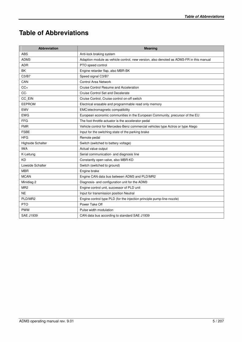
Table of Abbreviations
ADM3 operating manual rev. 9.01 5 / 207
Table of Abbreviations
Abbreviation Meaning
ABS Anti-lock braking system
ADM3 Adaption module as vehicle control, new version, also denoted as ADM3-FR in this manual
ADR PTO speed control
BK Engine retarder flap, also MBR-BK
C3/B7 Speed signal C3/B7
CAN Control Area Network
CC+ Cruise Control Resume and Acceleration
CC- Cruise Control Set and Decelerate
CC_EIN Cruise Control, Cruise control on-off switch
EEPROM Electrical erasable and programmable read only memory
EMV EMC/electromagnetic compatibility
EWG European economic communities in the European Community, precursor of the EU
FFG The foot throttle actuator is the accelerator pedal
FMR Vehicle control for Mercedes-Benz commercial vehicles type Actros or type Atego
FSBE Input for the switching state of the parking brake
HFG Remote pedal
Highside Schalter Switch (switched to battery voltage)
IWA Actual value output
K-Leitung Serial communication- and diagnosis line
KD Constantly open valve, also MBR-KD
Lowside Schalter Switch (switched to ground)
MBR Engine brake
MCAN Engine CAN data bus between ADM3 and PLD/MR2
Minidiag 2 Diagnosis- and configuration unit for the ADM3
MR2 Engine control unit, successor of PLD unit
NE Input for transmission position Neutral
PLD/MR2 Engine control type PLD (for the injection principle pump-line-nozzle)
PTO Power Take Off
PWM Pulse width modulation
SAE J1939 CAN data bus according to standard SAE J1939
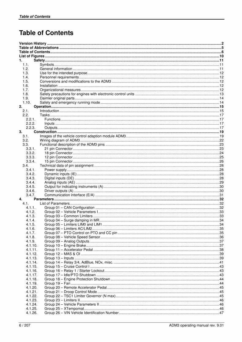
Table of Contents
6 / 207 ADM3 operating manual rev. 9.01
Table of Contents
Version History ..........................................................................................................................................................................2 Table of Abbreviations ..............................................................................................................................................................5 Table of Contents.......................................................................................................................................................................6 List of Figures ..........................................................................................................................................................................10 1. Safety..........................................................................................................................................................................11
1.1. Symbols.................................................................................................................................................................11 1.2. General information ...............................................................................................................................................11 1.3. Use for the intended purpose.................................................................................................................................12 1.4. Personnel requirements.........................................................................................................................................12 1.5. Conversions and modifications to the ADM3 .........................................................................................................12 1.6. Installation .............................................................................................................................................................12 1.7. Organizational measures.......................................................................................................................................12 1.8. Safety precautions for engines with electronic control units ..................................................................................13 1.9. Daimler original parts.............................................................................................................................................14 1.10. Safety and emergency running mode....................................................................................................................14
2. Operation....................................................................................................................................................................15 2.1. Introduction............................................................................................................................................................15 2.2. Tasks .....................................................................................................................................................................17
2.2.1. Functions...........................................................................................................................................................17 2.2.2. Inputs ................................................................................................................................................................17 2.2.3. Outputs..............................................................................................................................................................17
3. Construction ..............................................................................................................................................................19 3.1. Images of the vehicle control adaption module ADM3...........................................................................................19 3.2. Wiring diagram of ADM3........................................................................................................................................22 3.3. Functional description of the ADM3 pins ...............................................................................................................23
3.3.1. 21 pin Connector...............................................................................................................................................23 3.3.2. 18 pin Connector...............................................................................................................................................24 3.3.3. 12 pin Connector...............................................................................................................................................25 3.3.4. 15 pin Connector...............................................................................................................................................26
3.4. Technical data of pin assignment ..........................................................................................................................28 3.4.1. Power supply.....................................................................................................................................................28 3.4.2. Dynamic inputs (IE)...........................................................................................................................................28 3.4.3. Digital inputs (DE) .............................................................................................................................................28 3.4.4. Analog inputs (AE) ............................................................................................................................................29 3.4.5. Output for indicating instruments (A).................................................................................................................30 3.4.6. Driver outputs (A) ..............................................................................................................................................30 3.4.7. Communication interface (E/A) .........................................................................................................................31
4. Parameters .................................................................................................................................................................32 4.1. List of Parameters..................................................................................................................................................32
4.1.1. Group 01 – CAN Configuration .........................................................................................................................32 4.1.2. Group 02 – Vehicle Parameters I ......................................................................................................................33 4.1.3. Group 03 – Common Limiters ...........................................................................................................................33 4.1.4. Group 04 – Surge damping in MR.....................................................................................................................34 4.1.5. Group 05 – Limiters LIM0 and LIM1..................................................................................................................34 4.1.6. Group 06 – Limiters AC/LIM2............................................................................................................................35 4.1.7. Group 07 – PTO Control on PTO and CC pin ...................................................................................................35 4.1.8. Group 08 – Vehicle Speed Sensor....................................................................................................................36 4.1.9. Group 09 – Analog Outputs...............................................................................................................................37 4.1.10. Group 10 – Engine Brake..................................................................................................................................37 4.1.11. Group 11 – Accelerator Pedal ...........................................................................................................................38 4.1.12. Group 12 – MAS & OI .......................................................................................................................................39 4.1.13. Group 13 – Inputs .............................................................................................................................................39 4.1.14. Group 14 – Relay 3/4, AdBlue, NOx, misc. .......................................................................................................41 4.1.15. Group 15 – Cruise Control I ..............................................................................................................................43 4.1.16. Group 16 – Relay 1 / Starter Lockout................................................................................................................43 4.1.17. Group 17 – Idle/PTO Shutdown ........................................................................................................................43 4.1.18. Group 18 – Engine Protection Shutdown ..........................................................................................................44 4.1.19. Group 19 – Fan .................................................................................................................................................44 4.1.20. Group 20 – Remote Accelerator Pedal..............................................................................................................45 4.1.21. Group 21 – Droop Control Mode .......................................................................................................................45 4.1.22. Group 22 – TSC1 Limiter Governor (N max).....................................................................................................45 4.1.23. Group 23 – Limiters II........................................................................................................................................46 4.1.24. Group 24 – Vehicle Parameters II .....................................................................................................................46 4.1.25. Group 25 – XTempomat....................................................................................................................................46 4.1.26. Group 26 – VIN Vehicle Identification Number..................................................................................................47

Table of Contents
ADM3 operating manual rev. 9.01 7 / 207
4.1.27. Group 27 – Fleetmanagement ..........................................................................................................................47 4.1.28. Group 28 – Real Time Clock .............................................................................................................................47
4.2. Description of Parameters .....................................................................................................................................48 4.2.1. Group 01 – CAN Configuration .........................................................................................................................48 4.2.2. Group 02 – Vehicle Parameters I ......................................................................................................................49 4.2.3. Group 03 – Common Limiters ...........................................................................................................................50 4.2.4. Group 04 – Surge damping in MR.....................................................................................................................51 4.2.5. Group 05 – Limiters LIM0 and LIM1..................................................................................................................52 4.2.6. Group 06 – Limiters AC/LIM2............................................................................................................................53 4.2.7. Group 07 – PTO Control on PTO and CC pin ...................................................................................................54 4.2.8. Group 08 – Vehicle Speed Sensor....................................................................................................................55 4.2.9. Group 09 – Analog Outputs...............................................................................................................................56 4.2.10. Group 10 – Engine Brake..................................................................................................................................58 4.2.11. Group 11 – Accelerator Pedal ...........................................................................................................................60 4.2.12. Group 12 – MAS & OI .......................................................................................................................................61 4.2.13. Group 13 – Inputs .............................................................................................................................................61 4.2.14. Group 14 – Relay 3/4, AdBlue, NOx, misc. .......................................................................................................65 4.2.15. Group 15 – Cruise Control I ..............................................................................................................................69 4.2.16. Group 16 – Relay 1 / Starter Lockout................................................................................................................70 4.2.17. Group 17 – Idle/PTO Shutdown ........................................................................................................................70 4.2.18. Group 18 – Engine Protection Shutdown ..........................................................................................................71 4.2.19. Group 19 – Fan .................................................................................................................................................72 4.2.20. Group 20 – Remote Accelerator Pedal..............................................................................................................72 4.2.21. Group 21 – Droop Control Mode .......................................................................................................................73 4.2.22. Group 22 – TSC1 Limiter Governor (N max).....................................................................................................73 4.2.23. Group 23 – Limiters II........................................................................................................................................74 4.2.24. Group 24 – Vehicle Parameters II .....................................................................................................................74 4.2.25. Group 25 – XTempomat....................................................................................................................................74 4.2.26. Group 26 – VIN Vehicle Identification Number..................................................................................................74 4.2.27. Group 27 – Fleetmanagement ..........................................................................................................................75 4.2.28. Group 28 – Real Time Clock .............................................................................................................................75
5. Fitting and connecting ..............................................................................................................................................76 5.1. Operating data.......................................................................................................................................................76 5.2. Installation .............................................................................................................................................................76
5.2.1. Use in the vehicle..............................................................................................................................................78 5.2.2. Use in stationary engines..................................................................................................................................78
5.3. Connecting up........................................................................................................................................................79 6. Parameter programming with the diagnosis unit minidiag2..................................................................................80 7. Application .................................................................................................................................................................81
7.1. Driving mode and PTO speed control....................................................................................................................81 7.1.1. Driving mode.....................................................................................................................................................81 7.1.2. Cruise control operation ....................................................................................................................................83
7.2. PTO speed control (ADR)......................................................................................................................................86 7.2.1. The three operating modes of the PTO speed control ......................................................................................86 7.2.2. Governor types for the PTO speed control........................................................................................................89
7.3. Accelerator pedal/Remote accelerator pedal.........................................................................................................90 7.3.1. PWM accelerator pedal.....................................................................................................................................90 7.3.2. Analog accelerator pedal...................................................................................................................................91 7.3.3. Analog remote accelerator pedal (Manual throttle actuator)..............................................................................92
7.4. Engine start/stop....................................................................................................................................................93 7.4.1. Two alternatives for the engine start .................................................................................................................93 7.4.2. Three alternatives for engine stop.....................................................................................................................94 7.4.3. Service start button and service stop button at the engine block ......................................................................95
7.5. Engine brake (Retarder) ........................................................................................................................................96 7.5.1. Technical description exhaust flap ....................................................................................................................96 7.5.2. Technical description decompression valve......................................................................................................97 7.5.3. Engine brake configuration................................................................................................................................97 7.5.4. Activation of engine brake systems (Version 209) ..........................................................................................103 7.5.5. Deactivation of engine brake...........................................................................................................................104 7.5.6. Engine brake operation with a stalk switch......................................................................................................104
7.6. Instruments / Displays .........................................................................................................................................105 7.6.1. Rev counter.....................................................................................................................................................105 7.6.2. Coolant temperature gauge.............................................................................................................................105 7.6.3. Oil pressure gauge..........................................................................................................................................105 7.6.4. Coolant temperature indicator lamp ................................................................................................................105 7.6.5. Oil pressure indicator lamp..............................................................................................................................106 7.6.6. Oil level indicator lamp ....................................................................................................................................106 7.6.7. Configuration Indicator lamp and gauge .........................................................................................................107 7.6.8. Grid Heater indicator lamp ..............................................................................................................................107
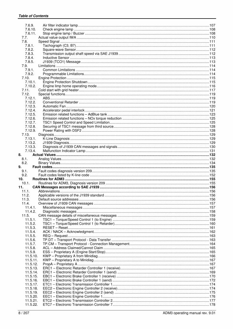
Table of Contents
8 / 207 ADM3 operating manual rev. 9.01
7.6.9. Air filter indicator lamp.....................................................................................................................................107 7.6.10. Check engine lamp .........................................................................................................................................108 7.6.11. Stop engine lamp / Buzzer ..............................................................................................................................108
7.7. Actual value output IWA ......................................................................................................................................110 7.8. Speed Signal .......................................................................................................................................................111
7.8.1. Tachograph (C3, B7).......................................................................................................................................111 7.8.2. Square-wave Sensor.......................................................................................................................................112 7.8.3. Transmission output shaft speed via SAE J1939............................................................................................112 7.8.4. Inductive Sensor .............................................................................................................................................113 7.8.5. J1939 (TCO1) Message..................................................................................................................................113
7.9. Limitations ...........................................................................................................................................................114 7.9.1. Common Limitations .......................................................................................................................................114 7.9.2. Programmable Limitations...............................................................................................................................114
7.10. Engine Protection ................................................................................................................................................115 7.10.1. Engine Protection Shutdown...........................................................................................................................115 7.10.2. Engine limp home operating mode..................................................................................................................116
7.11. Cold start with grid heater....................................................................................................................................117 7.12. Special functions..................................................................................................................................................119
7.12.1. ABS.................................................................................................................................................................119 7.12.2. Conventional Retarder ....................................................................................................................................119 7.12.3. Automatic Fan .................................................................................................................................................120 7.12.4. Accelerator pedal interlock..............................................................................................................................121 7.12.5. Emission related functions – AdBlue tank .......................................................................................................123 7.12.6. Emission related functions – NOx torque reduction ........................................................................................125 7.12.7. TSC1 Speed Control and Speed Limitation.....................................................................................................125 7.12.8. Securing of TSC1 message from third source.................................................................................................128 7.12.9. Power Rating with DSF2 .................................................................................................................................128
7.13. Diagnosis.............................................................................................................................................................129 7.13.1. K-Line Diagnosis .............................................................................................................................................129 7.13.2. J1939 Diagnosis..............................................................................................................................................129 7.13.3. Diagnosis of J1939 CAN messages and signals.............................................................................................130 7.13.4. Malfunction Indicator Lamp .............................................................................................................................131
8. Actual Values ...........................................................................................................................................................132 8.1. Analog Values......................................................................................................................................................132 8.2. Binary Values.......................................................................................................................................................134
9. Fault codes...............................................................................................................................................................135 9.1. Fault codes diagnosis version 209.......................................................................................................................135 9.2. Fault codes listed by K-line code .........................................................................................................................152
10. Routines for ADM3 ..................................................................................................................................................155 10.1. Routines for ADM3, Diagnosis version 209 .........................................................................................................155
11. CAN Messages according to SAE J1939 ...............................................................................................................156 11.1. Abbreviations.......................................................................................................................................................156 11.2. Applicable versions of the J1939 standard ..........................................................................................................156 11.3. Default source addresses ....................................................................................................................................156 11.4. Overview of J1939 CAN messages .....................................................................................................................157
11.4.1. Miscellaneous messages ................................................................................................................................157 11.4.2. Diagnostic messages ......................................................................................................................................158
11.5. CAN message details of miscellaneous messages .............................................................................................159 11.5.1. TSC1 – Torque/Speed Control 1 (to Engine) ..................................................................................................159 11.5.2. TSC1 – Torque/Speed Control 1 (to Retarder)................................................................................................160 11.5.3. RESET – Reset...............................................................................................................................................161 11.5.4. ACK / NACK – Acknowledgment.....................................................................................................................162 11.5.5. REQ – Request ...............................................................................................................................................163 11.5.6. TP.DT – Transport Protocol - Data Transfer ...................................................................................................163 11.5.7. TP.CM – Transport Protocol - Connection Management.................................................................................164 11.5.8. ACL – Address Claimed/Cannot Claim ...........................................................................................................165 11.5.9. ESS – Proprietary A (Engine Start/Stop).........................................................................................................165 11.5.10. KWP – Proprietary A from Minidiag.................................................................................................................166 11.5.11. KWP – Proprietary A to Minidiag.....................................................................................................................167 11.5.12. PropA – Proprietary A .....................................................................................................................................167 11.5.13. ERC1 – Electronic Retarder Controller 1 (receive)..........................................................................................167 11.5.14. ERC1 – Electronic Retarder Controller 1 (send) .............................................................................................169 11.5.15. EBC1 – Electronic Brake Controller 1 (receive) ..............................................................................................170 11.5.16. EBC1 – Electronic Brake Controller 1 (send) ..................................................................................................172 11.5.17. ETC1 – Electronic Transmission Controller 1..................................................................................................174 11.5.18. EEC2 – Electronic Engine Controller 2 (receive).............................................................................................174 11.5.19. EEC2 – Electronic Engine Controller 2 (send) ................................................................................................175 11.5.20. EEC1 – Electronic Engine Controller 1............................................................................................................176 11.5.21. ETC2 – Electronic Transmission Controller 2..................................................................................................177 11.5.22. ETC7 – Electronic Transmission Controller 7..................................................................................................178
Table of Contents
ADM3 operating manual rev. 9.01 9 / 207
11.5.23. TI1 – Tank Information 1 .................................................................................................................................179 11.5.24. TCO1 – Tachograph .......................................................................................................................................180 11.5.25. ACC1 – Adaptive Cruise Control.....................................................................................................................182 11.5.26. EBC2 – Wheel Speed Information ..................................................................................................................183 11.5.27. AUXIO1 – Auxiliary Input/Output Status 1.......................................................................................................183 11.5.28. SOFT – Software Identification .......................................................................................................................185 11.5.29. EEC3 – Electronic Engine Controller 3............................................................................................................185 11.5.30. VD – Vehicle Distance.....................................................................................................................................186 11.5.31. RC – Retarder Configuration...........................................................................................................................187 11.5.32. EC1 – Engine Configuration 1.........................................................................................................................188 11.5.33. HOURS – Engine Hours, Revolutions.............................................................................................................189 11.5.34. LFC – Fuel Consumption (Liquid) ...................................................................................................................189 11.5.35. CI – Component Identification .........................................................................................................................189 11.5.36. ET1 – Engine Temperature 1 ..........................................................................................................................190 11.5.37. EFL/P1 – Engine Fluid Level/Pressure 1 ........................................................................................................190 11.5.38. PTO – Power Takeoff Information...................................................................................................................191 11.5.39. CCVS – Cruise Control/Vehicle Speed (receive) ............................................................................................192 11.5.40. CCVS – Cruise Control/Vehicle Speed (send) ................................................................................................194 11.5.41. LFE – Fuel Economy (Liquid)..........................................................................................................................197 11.5.42. AMB – Ambient Conditions (receive) ..............................................................................................................197 11.5.43. AMB – Ambient Conditions (send) ..................................................................................................................197 11.5.44. IC1 – Inlet/Exhaust Conditions ........................................................................................................................198 11.5.45. VEP1 – Vehicle Electrical Power 1..................................................................................................................198 11.5.46. DD – Dash Display..........................................................................................................................................199
11.6. CAN message details of diagnostic messages....................................................................................................200 11.6.1. DM13 – Diagnostic Message 13, Stop Start Broadcast...................................................................................200 11.6.2. DM1 – Diagnostic Message 1, Active Diagnostic Trouble Codes (receive).....................................................201 11.6.3. DM1 – Diagnostic Message 1, Active Diagnostic Trouble Codes (send) ........................................................202 11.6.4. DM2 – Diagnostic Message 2, Previously Active Diagnostic Trouble Codes ..................................................204 11.6.5. DM3 – Diagnostic Message 3, Diagnostic Data Clear/Reset Of Previously Active DTCs ...............................205 11.6.6. DM4 – Diagnostic Message 4, Freeze Frame Parameters..............................................................................205 11.6.7. DM11 – Diagnostic Message 11, Diagnostic Clear/Reset For Active DTCs....................................................206

1. Safety
10 / 207 ADM3 operating manual rev. 9.01
List of Figures
Fig. 1: Adaption module as vehicle control (ADM3): ..........................................................................................................16 Fig. 2: Diagonal view of ADM3...........................................................................................................................................19 Fig. 3: Installation position in the vehicle or view of rear side of the ADM3........................................................................20 Fig. 4: View of connector side of ADM3.............................................................................................................................21 Fig. 5: Wiring diagram of ADM3.........................................................................................................................................22 Fig. 6: Brackets..................................................................................................................................................................76 Fig. 7: Mounting the ADM3 ................................................................................................................................................77 Fig. 8: Dimensioned block diagram of the bracket .............................................................................................................77 Fig. 9: Fitting position in the vehicle or the rear of the ADM3.............................................................................................78 Fig. 10: Stalk switch functions..............................................................................................................................................84 Fig. 11: Stalk switch wiring...................................................................................................................................................84 Fig. 12: Engine brake configuration: Exhaust flap only, driven by ADM3.............................................................................97 Fig. 13: Engine brake configuration: Exhaust flap only, exhaust flap at PLD/MR2 ..............................................................98 Fig. 14: Engine brake configuration: Decompression valve only, decompression valve at ADM3 .......................................99 Fig. 15: Engine brake configuration: Exhaust flap and decompression valve at one valve................................................100 Fig. 16: Engine brake configuration: Exhaust flap and decompression valve at two separate valves................................101 Fig. 17: Engine brake configuration: Exhaust flap at ADM3 and decompression valve at PLD/MR2.................................102 Fig. 18: Engine brake configuration: Exhaust flap and decompression valve at PLD/MR2................................................103 Fig. 19: Engine protection shutdown time..........................................................................................................................115 Fig. 20: Engine protection shutdown times on Oil pressure...............................................................................................116 Fig. 21: Fan control strategy ..............................................................................................................................................120 Fig. 22: I-component of control torque for engine speed control........................................................................................127 Fig. 23: P-component of control torque for engine speed control ......................................................................................127

1. Safety
ADM3 operating manual rev. 9.01 11 / 207
1. Safety
1.1. Symbols
The instructions which follow are shown against various symbols.
Risk of injury!
This symbol appears against all safety instructions which must be complied with in order to avoid a direct risk of danger to life and limb.
This symbol is used against all safety instructions which, if disregarded, could give rise to the danger of material damage or malfunctions.
1.2. General information
Risk of potentially fatal accident!
The ADM3 vehicle control adaption module is essential for defining the functions of the engine and vehicle. Functions such as engine start, engine stop, accelerator pedal evaluation, actuation of engine brake etc. are relevant to safety. Incorrectly performed modifications to the parameters or tampering with the wiring can cause far-reaching changes to the performance of the engine and/or vehicle. This can lead to personal injury and material damage.
The ADM3 control unit has been developed and tested in accordance with the Daimler Specifications for Operating Safety and EMC Compatibility. The manufacturer of the vehicle or equipment is solely responsible for the examination and implementation of applicable legal stipulations.
1. Safety
12 / 207 ADM3 operating manual rev. 9.01
1.3. Use for the intended purpose
The Mercedes-Benz Engine and the ADM3 control unit are only to be used for the purpose stated in the contract of purchase. Any other use or an extension of the stated use will be regarded as not conforming to the engine’s intended purpose. Daimler AG cannot accept any liability for damage resulting from such use. Liability for damage resulting from the engine not having been used for its intended purpose shall rest solely with the manufacturer of the complete machine or vehicle in which the engine is installed. These ADM3 Operating Instructions and the engine Operating Instructions must be observed.
1.4. Personnel requirements
Work on the electrics and programmed parameters must only be carried out by especially skilled persons or those who have received training from Daimler, or by specialists employed by a workshop authorized by Daimler.
1.5. Conversions and modifications to the ADM3
Unauthorized modifications to the ADM3 could affect the operation and safety of the vehicle/machine in which it is installed. No responsibility will be accepted for any resulting damage.
1.6. Installation
The guidelines and instructions in chapter 5 must be observed.
1.7. Organizational measures
These Operating Instructions should be handed to personnel entrusted with the operation of the ADM3 and should, whenever possible, be stored in an easily accessible place. With the aid of these Operating Instructions, personnel must be familiarized with the operation of the ADM3, paying special attention to the safety-relevant instructions applicable to the engine. This applies in particular to personnel who only work on the engine and ADM3 occasionally. In addition to these Operating Instructions, comply with local legal stipulations and any other obligatory accident prevention and environmental protection regulations which may apply in the country of operation.

1. Safety
ADM3 operating manual rev. 9.01 13 / 207
1.8. Safety precautions for engines with electronic control units
Risk of accident!
When the vehicle electrics are first operated, the drive train must be open (transmission in neutral). The engine could start unexpectedly due to incorrect wiring or unsuitable parameter programming. If the drive train is closed (transmission not in neutral), the vehicle could unexpectedly start moving or set the working machine in operation, constituting a risk to life and limb.
The safety precautions stated below must be applied at all times in order to avoid damage to the engine, its components and wiring, and to avoid possible personal injury.
• Only start the engine with the batteries securely connected. • Do not disconnect the batteries when the engine is running.
• Only start the engine with the engine speed sensor connected. • Do not start the engine with the aid of a rapid battery charger. If emergency starting is necessary, only start using
separate batteries. • The battery terminal clamps must be disconnected before a rapid charger is used. Comply with the operating instructions
for the rapid charger. • If electric welding work is to be performed, the batteries must be disconnected and both cables (+ and -) secured
together. • Work is only to be performed on the wiring and connectors are only to be plugged/unplugged with the electrical system
switched off. • The first time starting up the engine, the possibility must be provided to switch off the voltage supply to the PLD/MR2
engine control and to the ADM3 adaption module in an emergency. If it is incorrectly wired up, it may no longer be possible to switch off the engine.
• Interchanging the poles of the control unit’s voltage supply (e.g. by interchanging the battery poles) can damage the control unit beyond repair.
• Fasten connectors on the fuel injection system with the specified tightening torque.
• Only use properly fitting test leads for measurements on plug connectors (Daimler connector set).
If temperatures in excess of 80 °C (e.g. in a drying kiln) are to be expected, the control units must be removed as they could be damaged by such temperatures. Telephones and two-way radios which are not connected to an external aerial can cause malfunctions in the vehicle electronics and thus jeopardize the engine’s operating safety.

1. Safety
14 / 207 ADM3 operating manual rev. 9.01
1.9. Daimler original parts
Daimler original parts are subject to the most stringent quality checks and guarantee maximum functional efficiency, safety and retention of value. Each part is specially designed, produced, selected and approved for Daimler. For this reason, we are obliged to disclaim all liability for damage resulting from the use of parts and accessories which do not meet the above requirements. In Germany and various other countries, certain parts (for instance parts relevant to safety) are only officially approved for installation or conversion work if they comply with valid legal stipulations. These regulations are assured to be satisfied by Daimler original parts. If other parts, which have not been tested and approved by Daimler, are installed - even if in individual circumstances they have been granted an official operating permit - Daimler is unable to assess them or grant any form of warranty, although the company endeavors to monitor market developments as far as possible. The installation of such parts may therefore restrict the validity of the warranty.
1.10. Safety and emergency running mode
The ADM3, FMR and PLD/MR2 electronic engine control units monitor the engine and carry out self-diagnosis. As soon as a fault is detected it is evaluated by the control unit and one of the following measures is initiated:
• Faults during operation are indicated by the warning lamps being activated. • Switch-over to a suitable substitute function for continued, albeit restricted engine operation (e.g. constant emergency
engine speed). Have any faults rectified without delay by the responsible Daimler Service Station.
Note: The Daimler diagnosis tester minidiag2 is connected to the 14 pin diagnosis socket (on the unit). The minidiag2 can be used to read off the fault codes of the ADM3. ADM3 fault codes and their meanings are described in chapter 9. Note: Defective units which are still within the period of warranty cover (6 months from Daimler dispatch date) must be returned to the Daimler field service organization.
2. Operation
ADM3 operating manual rev. 9.01 15 / 207
2. Operation
2.1. Introduction
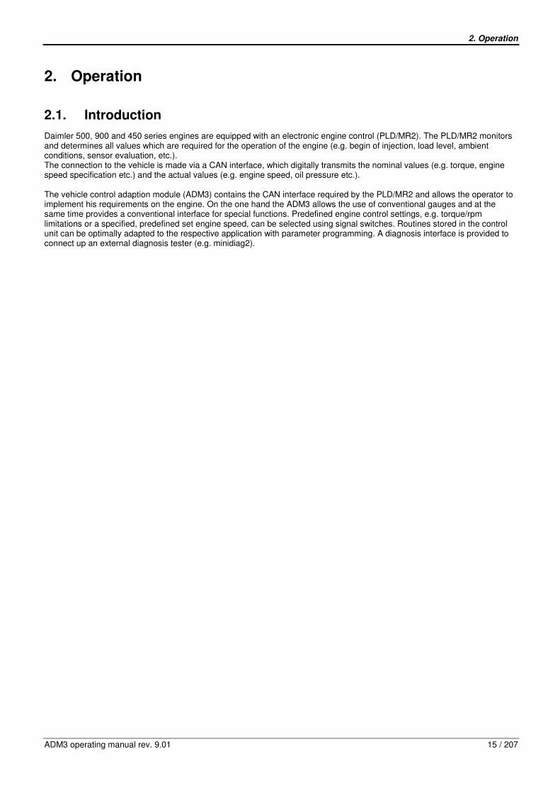
Daimler 500, 900 and 450 series engines are equipped with an electronic engine control (PLD/MR2). The PLD/MR2 monitors and determines all values which are required for the operation of the engine (e.g. begin of injection, load level, ambient conditions, sensor evaluation, etc.). The connection to the vehicle is made via a CAN interface, which digitally transmits the nominal values (e.g. torque, engine speed specification etc.) and the actual values (e.g. engine speed, oil pressure etc.). The vehicle control adaption module (ADM3) contains the CAN interface required by the PLD/MR2 and allows the operator to implement his requirements on the engine. On the one hand the ADM3 allows the use of conventional gauges and at the same time provides a conventional interface for special functions. Predefined engine control settings, e.g. torque/rpm limitations or a specified, predefined set engine speed, can be selected using signal switches. Routines stored in the control unit can be optimally adapted to the respective application with parameter programming. A diagnosis interface is provided to connect up an external diagnosis tester (e.g. minidiag2).

2. Operation
16 / 207 ADM3 operating manual rev. 9.01
Fig. 1: Adaption module as vehicle control (ADM3): ABS = Anti-block brake system ADR = PTO speed control ABS/ASR = Control unit for anti-block brake system or traction control BGR = Limitations FFG = Accelerator pedal: torque demand (driving mode) or speed demand (PTO operating mode) FLA = Flame-start system Gearbox = Control unit for the transmission ISO = International Organization for Standardization (e.g. diagnostic line / ISO 9141) IWA = Actual value output (for automatic transmission, customer-specific electronics,...) MBR = Engine brake MR = Engine control for the injection principle pump-line-nozzle (is in this case PLD/MR2) Retarder = Control unit for a retarder SAE J1939 = Data bus according to standard SAE J1939

2. Operation
ADM3 operating manual rev. 9.01 17 / 207
2.2. Tasks
The tasks of the ADM3 can be split into three areas: − Functions − Inputs − Outputs
2.2.1. Functions
• Driving mode: torque demand to engine control (PLD/MR2)
• PTO speed control: Specified rpm to engine control (PLD/MR2). • Engine start, engine stop • Accelerator pedal evaluation, monitoring, fault evaluation • Engine brakes
• Speed limitation • Cruise control • Temposet
• Parameter memory • Fault memory • Diagnosis interface for a diagnosis unit e.g. Minidiag2
• Diagnosis intersections: Implementation of K-wire diagnosis to CAN diagnosis only for the engine control PLD/MR2 • Linking with SAE J1939 (High-Speed-CAN-Bus)
2.2.2. Inputs
The ADM3 has digital inputs for
• Special functions, e.g. linkup with conventional ABS control unit
• External engine start and engine stop • Engine Protection Shutdown • Activating limitations
• Speed adjustment • Parking brake and driving brake • Cruise control
• Engine brake (stage 1 and stage 2) • Transmission „neutral“ position • Rear axle
Note: The function is not yet available for the inputs reverse gear, clutch 2 and generator terminal W. The ADM3 has analog inputs for
• Accelerator pedal (analog foot throttle actuator)
• Remote accelerator pedal (analog manual throttle actuator) • Coolant level sensor • Air filter sensor
2.2.3. Outputs
The ADM3 has outputs for • Engine brakes (engine retarder flap and constantly open valve) • Connection of indicator and warning lamps
− Oil level − Lamp red with buzzer (engine stop) − Lamp yellow for interference (e.g. oil pressure too low) − Heater flange (cold-start device) − Air filter
• Connection of measuring instruments − Oil pressure*

2. Operation
18 / 207 ADM3 operating manual rev. 9.01
− Coolant temperature* − Engine speed
• Customer-specific electronics − Actual value output IWA (e.g. for automatic transmission) − Relay output (e.g. kickdown)
Note*: Either measuring instruments or warning lamps can be connected to the instrument outputs for oil pressure and for coolant temperature.

3. Construction
ADM3 operating manual rev. 9.01 19 / 207
3. Construction
3.1. Images of the vehicle control adaption module ADM3
Fig. 2: Diagonal view of ADM3 Black space for the type label Connector sizes from the left to the right: - Connector 15 pin - Connector 18 pin - Connector 12 pin - Connector 21 pin

3. Construction
20 / 207 ADM3 operating manual rev. 9.01
Fig. 3: Installation position in the vehicle or view of rear side of the ADM3 Connector sizes from the left to the right: - Connector 21 pin - Connector 12 pin - Connector 18 pin - Connector 15 pin

3. Construction
ADM3 operating manual rev. 9.01 21 / 207
Fig. 4: View of connector side of ADM3 Connector sizes from the left to the right: - Connector 15 pin - Connector 18 pin - Connector 12 pin - Connector 21 pin
3. Construction
22 / 207 ADM3 operating manual rev. 9.01
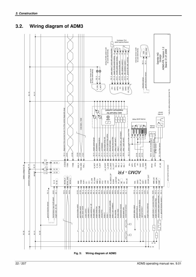
3.2. Wiring diagram of ADM3
15/0
8
15/
12
15/
09
15/
11
18/
01
21/
08
21/
07
21/
05
21/
06
21/
04
12/
04
12/
06
12/
03
21/
20
21/
21
21/
19
21/
18
21/
17
12/
02
15/
04
15/
10
15/
06
15/
03
12/0
5
12/0
7
12/0
8
12/0
9
12/1
0
12/1
1
15/0
1
15/0
7
15/0
2
18/1
2
18/1
3
18/1
4
18/1
5
18/1
6
18/0
7
18/0
8
18/0
9
18/1
0
18/1
1
21/1
5
21/1
6
18/0
2
18/0
4
18/0
5
18/0
6
diag
nos
is K
lin
e (c
onne
ct t
o pi
n 14
of t
he c
ent
ral d
iagn
ost
ic p
lug
)
Kl.
W
MC
AN
_H
Kl.
50
MC
AN
_GN
D
MC
AN
_L
BR
E
FS
BE
KU
P1
CC
-
CC
+
CC
_E
IN
MB
R_L
PT
O
LIM
0
LIM
1
M_A
BS
CH
_SP
KL
IMA
LUE
FT
ER
FP
_SP
HA
KW
_SE
IWA
DS
F2
DS
F1
DS
F0
ST
OP
P_E
XT
MB
R_K
D
C3/
B7
NE
n. c
. (g
rou
nd in
duc
tive
sen
sor
)
FG
_Wah
l
MB
R_H
MB
R_B
Kve
hicl
e s
pee
d si
gna
l (sp
eed
omet
.)
engi
ne b
rake
2 (
exh
aust
fla
p)
engi
ne b
rake
1 (
con
stan
t thr
ottle
)
engi
ne s
top
(e
xter
nal)
spec
ial f
unct
ion
2
actu
al v
alu
e ou
tput
cool
ant
leve
l sen
sor
12/
12tr
ans
mis
sion
inp
ut s
haft
spe
ed
Kl.
31
Kl.
15
Kl.
30
eng
ine
sta
rt
(Kl.
50)
12/
01
dual
spe
ed
axle
tra
nsm
issi
on n
eutr
al
thro
ttle
inhi
bit
fan
over
ride
limite
r 2
(ai
r co
nditi
on)
engi
ne s
hut
dow
n o
verr
ide
limite
r 1
limite
r 0
crui
se c
ont
rol +
engi
ne b
rake
hig
h
engi
ne b
rake
low
thro
ttle
se
lect
crui
se c
ont
rol o
n / o
ff
crui
se c
ont
rol -
20%
clu
tch
switc
h
park
bra
ke s
witc
h
serv
ice
bra
ke s
witc
h
Kl.
50
Kl. 15
Kl. 31
Kl. 15
Kl. 31
Kl. 30
15/1
3
15/1
4
15/1
5
193
9_H
1939
_G
ND
1939
_L
K-D
IAG
1708
A
1708
B
pow
er
supp
ly t
hrot
tle p
eda
l PW
M
rela
y 1
(spl
it va
lve2
)
rela
y 2
(idle
pos
., g
rid h
eat
er)
rela
y 3
rela
y 4
(spl
it va
lve1
)
wa
rnin
g la
mp
air
filte
r
lam
p gr
id h
eate
r
stop
en
gine
lam
p r
ed
oder
see manual for maximum current
che
ck e
ngi
ne la
mp
yello
w
LA O
els
tand
coo
lant
tem
per
atu
re
eng
ine
spe
ed g
aug
e
oil p
ress
ure
N_
MO
T
P_O
EL
T_
MO
T
LA_S
TO
PP
LA
_A
DM
LA_G
RID
LA_L
UF
T
RE
L 4
RE
L 3
RE
L 2
RE
L 1
AF
P+
AF
PS
FP
-
GA
S1
GA
S2
LG
_G
ND
HF
GS
HF
G+
LF_S
E
FP
+
CA
N S
AE
J 1
939
21/03
21/01
10 A
P_O
EL
T_
MO
T
gau
ges
/ la
mp
s co
uld
be
use
d al
tern
ativ
ely
air filter sensor
21/
13
21/
12
21/
14
15/0
5
125346
throttle pedal PWM
ADM3 -FR
grou
nd
Kl.
31
switc
hed
vo
ltag
e (ig
niti
on)
Kl.
15
batt
ery
volta
ge K
l. 30
Kl.
31
Kl.
15
PW
M
PWM
+ +- -
1
2
3
4
56
Dai
mle
r A
GT
P/P
EP
AD
M3-
FR
, Ver
sion
1.2
Sta
nd: 3
1.0
7.20
09
rem
ote
PT
O
mhhh
pin
s m
ust
be c
onn
ect
ed
12/
03
12/
04
air
filte
r se
nso
r
ST
_SP
En
gine
cra
nk in
hibi
t (B
US
)
remote throttle
supp
ly r
emo
te th
rottl
e,
air
filte
r se
nso
r
rem
ote
thro
ttle
sign
al
18/1
7
18/1
8
split
spec
ial f
unc
tion
1
ana
log
thro
ttle
ped
al c
ould
b
e us
ed
alte
rnat
ivel
y
VS
S1
5/04
15/
03
gro
und
ind
uctiv
e se
nso
r
indu
ctiv
e s
enso
r
indu
ctiv
e s
enso
rco
uld
be
use
d a
ltern
ativ
ely
VS
S_
GN
D
21/02
5 A *
* o
nly
for
cabl
e pr
otec
tion
(te
rmin
al 1
5)
18/
03
21/
13
21/
12
21/
14
21/
11
21/
09
15/
05
idle
val
ida
tion
sw
itch
1
idle
val
ida
tion
sw
itch
2
grou
nd th
rott
le p
edal
thro
ttle
peda
l sig
nal a
nal
og
sup
ply
thro
ttle
peda
l ana
log
gear
out
put 1
(on
ly w
ith a
nalo
g th
rottl
e)
grou
nd id
le v
alid
. sw
itche
s
AF
P+
AF
PS
FP
-
GA
S1
GA
S2
LG
_GN
D
FP
+
FEDCBA
analog throttle pedal(e.g. Williams)
15/
04gr
ound
ind
uctiv
e se
nso
r
Fig. 5: Wiring diagram of ADM3

3. Construction
ADM3 operating manual rev. 9.01 23 / 207
3.3. Functional description of the ADM3 pins
3.3.1. 21 pin Connector
21 pin connector
pin type function shortcut description
21/01 battery voltage Kl. 30 supply voltage (12V/24V)
21/02 DE ignition (switched battery voltage)
Kl. 15 ignition switch (terminal 15)
21/03 Ground Kl. 31 battery ground
21/04 A warning lamp oil level LA_OELST
Output active, if oil level too low. Feature only available if oil level sensing enabled.
If output is active while engine is running, shut down engine immediately and initiate a maintenance respectively an error diagnosis as soon as possible.
21/05 A stop engine lamp (buzzer) LA_STOP
output active, if major faults active, e.g. oil pressure very low
If output is active while engine is running, shut down engine immediately and initiate a maintenance respectively an error diagnosis as soon as possible.
21/06 A check engine lamp (yellow) LA_ADM
output active, if faults active, e.g. oil pressure too low or ecu detects external input and output faults.
If output is active while engine is running, shut down engine immediately and initiate a maintenance respectively an error diagnosis as soon as possible.
21/07 A lamp Grid heater LA_GRID output active, while preheating phase. Lamp off shows engine start is enabled.
21/08 A warning lamp air filter LA_LUFT output active, if air filter loaded.
21/09 power supply throttle pedal analog
AFP+ power supply of analog throttle pedal, e.g. Williams pedal terminal C.
21/10 reserved
21/11 AE throttle pedal signal analog AFPS sensor voltage proportional to pedal position e.g. input for Williams pedal terminal A.
PWM throttle signal, path 1 sensor signal PWM pedal path 1, e.g. VDO pedal terminal 2/9
21/12 IE idle validation switch 2 (throttle active)
GAS1 e.g. Williams pedal terminal D
PWM throttle signal, path 2 sensor signal PWM pedal path 2, e.g. VDO pedal terminal 4/9
21/13 IE idle validation switch 1 (idle active)
GAS2 e.g. Williams pedal terminal E
PWM pedal ground, e.g. VDO pedal terminal 1/9 and 3/9. 21/14 ground throttle pedal FP-
analog pedal ground, e.g. Williams pedal terminal B
21/15 DE service brake switch BRE switch to ground. Switch open, if service brake is depressed
21/16 DE park brake switch FSBE switch to ground. Switch closed, if park brake is engaged
21/17 E/A SAE 1708, A 1708A available since diagnosis version 203
21/18 E/A SAE 1708, B 1708B available since diagnosis version 203
21/19 E/A SAE J1939 CAN High (vehicle can)
1939_H SAE 1939 vehicle CAN high line
21/20 CAN HF Ground 1939_GND SAE J1939 (HF-ground).
21/21 E/A SAE J1939 CAN Low (vehicle can)
1939_L SAE 1939 vehicle CAN low line
A = output E/A = input/output (bidirectional) DE = digital input AE = analog input IE = pulse input
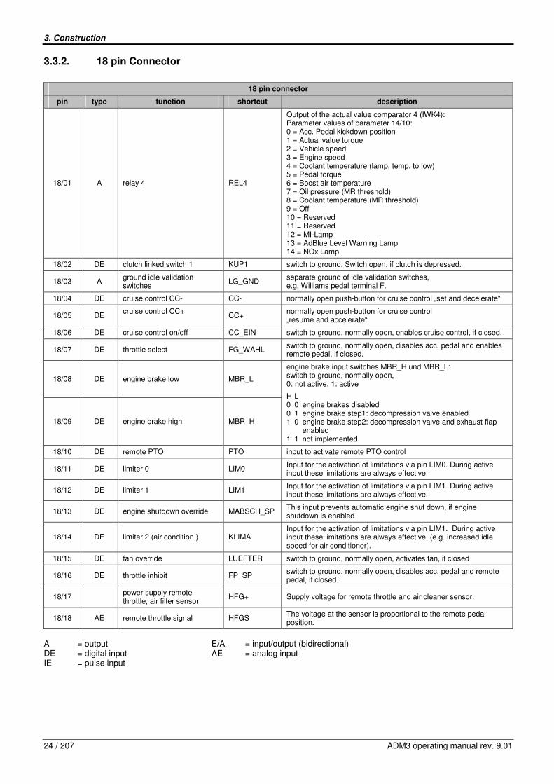
3. Construction
24 / 207 ADM3 operating manual rev. 9.01
3.3.2. 18 pin Connector
18 pin connector
pin type function shortcut description
18/01 A relay 4 REL4
Output of the actual value comparator 4 (IWK4): Parameter values of parameter 14/10: 0 = Acc. Pedal kickdown position 1 = Actual value torque 2 = Vehicle speed 3 = Engine speed 4 = Coolant temperature (lamp, temp. to low) 5 = Pedal torque 6 = Boost air temperature 7 = Oil pressure (MR threshold) 8 = Coolant temperature (MR threshold) 9 = Off 10 = Reserved 11 = Reserved 12 = MI-Lamp 13 = AdBlue Level Warning Lamp 14 = NOx Lamp
18/02 DE clutch linked switch 1 KUP1 switch to ground. Switch open, if clutch is depressed.
18/03 A ground idle validation switches
LG_GND separate ground of idle validation switches, e.g. Williams pedal terminal F.
18/04 DE cruise control CC- CC- normally open push-button for cruise control „set and decelerate“
18/05 DE cruise control CC+
CC+ normally open push-button for cruise control „resume and accelerate“.
18/06 DE cruise control on/off CC_EIN switch to ground, normally open, enables cruise control, if closed.
18/07 DE throttle select FG_WAHL switch to ground, normally open, disables acc. pedal and enables remote pedal, if closed.
18/08 DE engine brake low
MBR_L
18/09 DE engine brake high MBR_H
engine brake input switches MBR_H und MBR_L: switch to ground, normally open, 0: not active, 1: active
H L 0 0 engine brakes disabled 0 1 engine brake step1: decompression valve enabled 1 0 engine brake step2: decompression valve and exhaust flap enabled 1 1 not implemented
18/10 DE remote PTO PTO input to activate remote PTO control
18/11 DE limiter 0 LIM0 Input for the activation of limitations via pin LIM0. During active input these limitations are always effective.
18/12 DE limiter 1 LIM1 Input for the activation of limitations via pin LIM1. During active input these limitations are always effective.
18/13 DE engine shutdown override MABSCH_SP This input prevents automatic engine shut down, if engine shutdown is enabled
18/14 DE limiter 2 (air condition ) KLIMA Input for the activation of limitations via pin LIM1. During active input these limitations are always effective, (e.g. increased idle speed for air conditioner).
18/15 DE fan override LUEFTER switch to ground, normally open, activates fan, if closed
18/16 DE throttle inhibit FP_SP switch to ground, normally open, disables acc. pedal and remote pedal, if closed.
18/17 power supply remote
throttle, air filter sensor HFG+ Supply voltage for remote throttle and air cleaner sensor.
18/18 AE remote throttle signal HFGS The voltage at the sensor is proportional to the remote pedal position.
A = output E/A = input/output (bidirectional) DE = digital input AE = analog input IE = pulse input
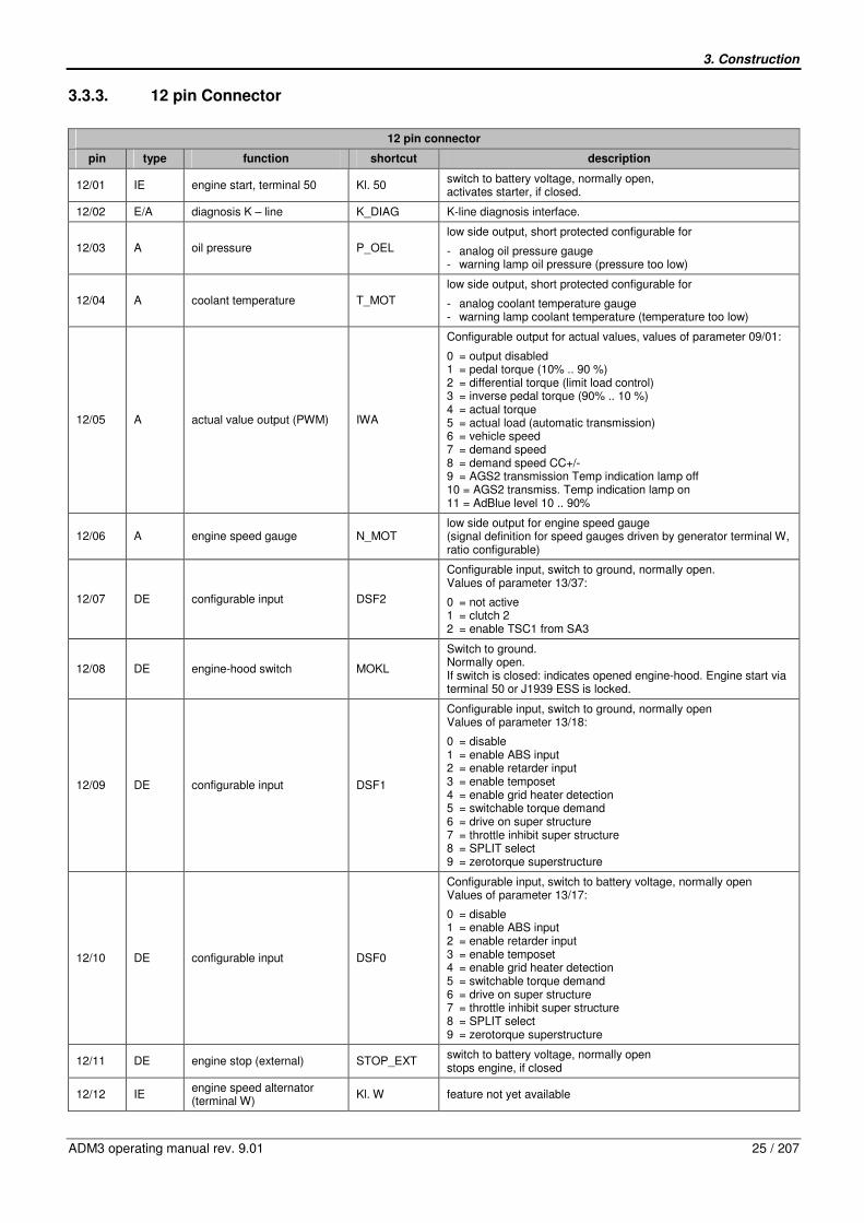
3. Construction
ADM3 operating manual rev. 9.01 25 / 207
3.3.3. 12 pin Connector
12 pin connector
pin type function shortcut description
12/01 IE engine start, terminal 50 Kl. 50 switch to battery voltage, normally open, activates starter, if closed.
12/02 E/A diagnosis K – line K_DIAG K-line diagnosis interface.
12/03 A oil pressure P_OEL
low side output, short protected configurable for
- analog oil pressure gauge - warning lamp oil pressure (pressure too low)
12/04 A coolant temperature T_MOT
low side output, short protected configurable for
- analog coolant temperature gauge - warning lamp coolant temperature (temperature too low)
12/05 A actual value output (PWM) IWA
Configurable output for actual values, values of parameter 09/01:
0 = output disabled 1 = pedal torque (10% .. 90 %) 2 = differential torque (limit load control) 3 = inverse pedal torque (90% .. 10 %) 4 = actual torque 5 = actual load (automatic transmission) 6 = vehicle speed 7 = demand speed 8 = demand speed CC+/- 9 = AGS2 transmission Temp indication lamp off 10 = AGS2 transmiss. Temp indication lamp on 11 = AdBlue level 10 .. 90%
12/06 A engine speed gauge N_MOT low side output for engine speed gauge (signal definition for speed gauges driven by generator terminal W, ratio configurable)
12/07 DE configurable input DSF2
Configurable input, switch to ground, normally open. Values of parameter 13/37:
0 = not active 1 = clutch 2 2 = enable TSC1 from SA3
12/08 DE engine-hood switch MOKL
Switch to ground. Normally open. If switch is closed: indicates opened engine-hood. Engine start via terminal 50 or J1939 ESS is locked.
12/09 DE configurable input DSF1
Configurable input, switch to ground, normally open Values of parameter 13/18:
0 = disable 1 = enable ABS input 2 = enable retarder input 3 = enable temposet 4 = enable grid heater detection 5 = switchable torque demand 6 = drive on super structure 7 = throttle inhibit super structure 8 = SPLIT select 9 = zerotorque superstructure
12/10 DE configurable input DSF0
Configurable input, switch to battery voltage, normally open Values of parameter 13/17:
0 = disable 1 = enable ABS input 2 = enable retarder input 3 = enable temposet 4 = enable grid heater detection 5 = switchable torque demand 6 = drive on super structure 7 = throttle inhibit super structure 8 = SPLIT select 9 = zerotorque superstructure
12/11 DE engine stop (external) STOP_EXT switch to battery voltage, normally open stops engine, if closed
12/12 IE engine speed alternator (terminal W)
Kl. W feature not yet available
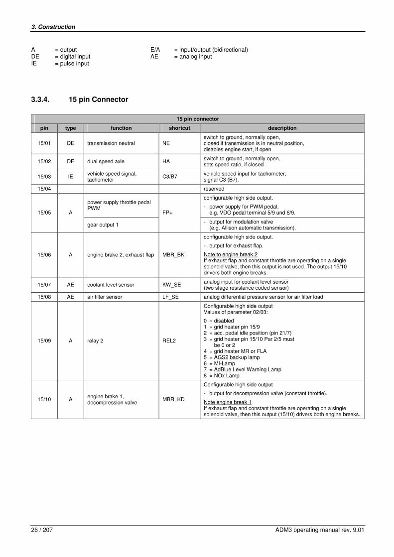
3. Construction
26 / 207 ADM3 operating manual rev. 9.01
A = output E/A = input/output (bidirectional) DE = digital input AE = analog input IE = pulse input
3.3.4. 15 pin Connector
15 pin connector
pin type function shortcut description
15/01 DE transmission neutral NE switch to ground, normally open, closed if transmission is in neutral position, disables engine start, if open
15/02 DE dual speed axle HA switch to ground, normally open, sets speed ratio, if closed
15/03 IE vehicle speed signal, tachometer
C3/B7 vehicle speed input for tachometer, signal C3 (B7).
15/04 reserved
power supply throttle pedal PWM
configurable high side output.
- power supply for PWM pedal, e.g. VDO pedal terminal 5/9 und 6/9. 15/05 A
gear output 1
FP+
- output for modulation valve (e.g. Allison automatic transmission).
15/06 A engine brake 2, exhaust flap MBR_BK
configurable high side output.
- output for exhaust flap.
Note to engine break 2 If exhaust flap and constant throttle are operating on a single solenoid valve, then this output is not used. The output 15/10 drivers both engine breaks.
15/07 AE coolant level sensor KW_SE analog input for coolant level sensor (two stage resistance coded sensor)
15/08 AE air filter sensor LF_SE analog differential pressure sensor for air filter load
15/09 A relay 2 REL2
Configurable high side output Values of parameter 02/03:
0 = disabled 1 = grid heater pin 15/9 2 = acc. pedal idle position (pin 21/7) 3 = grid heater pin 15/10 Par 2/5 must be 0 or 2 4 = grid heater MR or FLA 5 = AGS2 backup lamp 6 = MI-Lamp 7 = AdBlue Level Warning Lamp 8 = NOx Lamp
15/10 A engine brake 1, decompression valve
MBR_KD
Configurable high side output.
- output for decompression valve (constant throttle).
Note engine break 1 If exhaust flap and constant throttle are operating on a single solenoid valve, then this output (15/10) drivers both engine breaks.
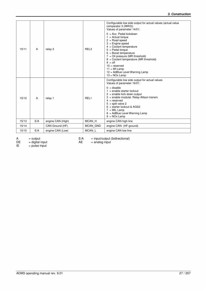
3. Construction
ADM3 operating manual rev. 9.01 27 / 207
15/11 A relay 3 REL3
Configurable low side output for actual values (actual value comparator 3 (IWK3)) Values of parameter 14/01:
0 = Acc. Pedal kickdown 1 = Actual torque 2 = Road speed 3 = Engine speed 4 = Coolant temperature 5 = Pedal torque 6 = Boost temperature 7 = Oil pressure (MR threshold) 8 = Coolant temperature (MR threshold) 9 = off 10 = reserved 11 = MI-Lamp 12 = AdBlue Level Warning Lamp 13 = NOx Lamp
15/12 A relay 1 REL1
Configurable low side output for actual values Values of parameter 16/01:
0 = disable 1 = enable starter lockout 2 = enable kick down output 3 = enable modulat. Relay Allison transm. 4 = reserved 5 = split valve 2 6 = starter lockout & AGS2 7 = MIL Lamp 8 = AdBlue Level Warning Lamp 9 = NOx Lamp
15/13 E/A engine CAN (High) MCAN_H engine CAN high line
15/14 CAN Ground (HF) MCAN_GND engine CAN- (HF-ground)
15/15 E/A engine CAN (Low) MCAN_L engine CAN low line
A = output E/A = input/output (bidirectional) DE = digital input AE = analog input IE = pulse input

3. Construction
28 / 207 ADM3 operating manual rev. 9.01
3.4. Technical data of pin assignment
3.4.1. Power supply
Power supply
pin function abbreviation UMAX UMIN IMAX further data
300 mA no external load
21/01 battery voltage Kl. 30
32 V at UB=24 V, 16 V at UB=12V
16 V at UB=24 V, 10 V at UB=12V 50 µA ADM3 switched off
21/02 ignition (switched battery voltage)
Kl. 15 UB Pull down resistor 30 kOhm
21/03 ground Kl. 31 battery ground
21/09 power supply throttle pedal analog
AFP+ 5 V 5 V 10 mA stabilized and short protected
100 mA
short protected, ground connection for PWM FFG, e.g. VDO FFG, terminal1/9 und 3/9. 21/14 ground throttle pedal FP-
100 mA short protected, ground connection for analog FFG, e.g. Williams FFG terminal B.
18/17 power supply remote throttle, air filter sensor
HFG+ 5 V 5 V 10 mA stabilized and short protected
15/04 reserved
3.4.2. Dynamic inputs (IE)
Dynamic inputs (IE)
pin function abbreviation f ULOW UHIGH further data
PWM throttle signal, path 1 220 Hz pull up resistor, 39kOhm
21/12 idle validation switch 2 (throttle active)
GAS1
< 1,5 V > 5,5 V pull up resistor, 39kOhm
PWM throttle signal, path 2 220 Hz pull up resistor 39 kOhm
21/13 idle validation switch 1 (idle active)
GAS2
< 1,5 V > 5,5 V pull up resistor, 39kOhm
15/03 vehicle speed signal, tachometer
C3/B7 < 2,5 V > 6,4 V pull down resistor47 kOhm
12/01 engine start, terminal 50 Kl. 50 < 4,0 V > 6,6 V rising edge detection, pull down resistor 7,7 kOhm
12/12 reserved
3.4.3. Digital inputs (DE)
Digital inputs (DE)
pin function abbreviation UMAX UMIN ULOW UHIGH further data
21/15 service brake switch BRE UB 0 V < 3,0 V > 7,0 V pull up resistor 2,35 kOhm
21/16 park brake switch FSBE UB 0 V < 3,0 V > 7,0 V pull up resistor 2,35 kOhm
18/02 clutch switch KUP1 UB 0 V < 3,0 V > 7,0 V pull up resistor 5 kOhm

3. Construction
ADM3 operating manual rev. 9.01 29 / 207
Digital inputs (DE)
pin function abbreviation UMAX UMIN ULOW UHIGH further data
18/04 cruise control CC- CC- UB 0 V < 3,0 V > 7,0 V pull up resistor 5 kOhm
18/05 cruise control CC+ CC+ UB 0 V < 3,0 V > 7,0 V pull up resistor 5 kOhm
18/06 cruise control on/off CC_EIN UB 0 V < 3,0 V > 7,0 V pull up resistor 5 kOhm
18/07 throttle select FG_WAHL UB 0 V < 3,0 V > 7,0 V pull up resistor 5 kOhm
18/08 engine brake low MBR_L UB 0 V < 3,0 V > 7,0 V pull up resistor 5 kOhm
18/09 engine brake high MBR_H UB 0 V < 3,0 V > 7,0 V pull up resistor 5 kOhm
18/10 remote PTO PTO UB 0 V < 3,0 V > 7,0 V pull up resistor 5 kOhm
18/11 limiter 0 LIM0 UB 0 V < 3,0 V > 7,0 V pull up resistor 5 kOhm
18/12 limiter1 LIM1 UB 0 V < 3,0 V > 7,0 V pull up resistor 2,35 kOhm
18/13 engine shutdown override MABSCH_SP UB 0 V < 3,0 V > 7,0 V pull up resistor 5 kOhm
18/14 limiter 2 (air condition ) KLIMA UB 0 V < 3,0 V > 7,0 V pull up resistor 2,35 kOhm
18/15 fan override LUEFTER UB 0 V < 3,0 V > 7,0 V pull up resistor 5 kOhm
18/16 throttle inhibit FP_SP UB 0 V < 3,0 V > 7,0 V pull up resistor 5 kOhm
15/01 transmission neutral NE UB 0 V < 3,0 V > 7,0 V pull up resistor 2,35 kOhm
15/02 dual speed axle HA UB 0 V < 3,0 V > 7,0 V pull up resistor 5 kOhm
12/07 feature not yet available
12/08 feature not yet available
12/09 configurable input DSF1 UB 0 V < 3,0 V > 7,0 V pull up resistor 2,35 kOhm
12/10 configurable input DSF0 UB 0 V < 3,5 V > 8,2 V pull down resistor 7,7kOhm
12/11 engine stop (external)
STOP_EXT UB 0 V < 3,5 V > 8,2 V pull down resistor 7,7kOhm
3.4.4. Analog inputs (AE)
Analog inputs (AE)
pin function abbreviation UMAX UMIN further data
21/11 throttle pedal signal analog AFPS 5 V 0 V e.g. Williams pedal terminal A, pull down resistor 47 kOhm to ground
18/18 remote throttle signal HFGS 5 V 0 V pull up resistor 200 kOhm to 5 V
15/07 coolant level sensor KW_SE 5 V 0 V pull up resistor 440 Ohm to 5 V
15/08 air filter sensor LF_SE 5 V 0 V pull up resistor 200 kOhm to 5 V
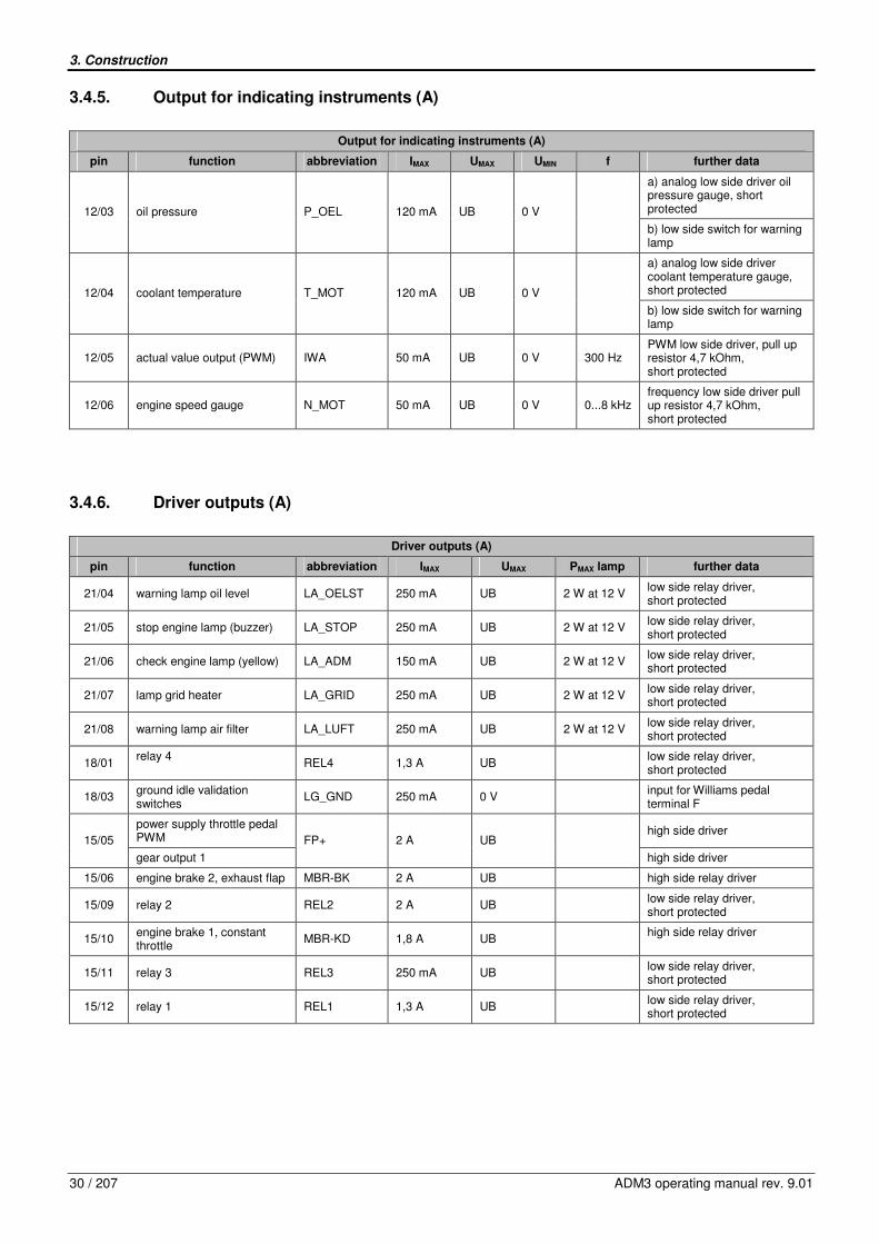
3. Construction
30 / 207 ADM3 operating manual rev. 9.01
3.4.5. Output for indicating instruments (A)
Output for indicating instruments (A)
pin function abbreviation IMAX UMAX UMIN f further data
a) analog low side driver oil pressure gauge, short protected 12/03 oil pressure P_OEL 120 mA UB 0 V
b) low side switch for warning lamp
a) analog low side driver coolant temperature gauge, short protected 12/04 coolant temperature T_MOT 120 mA UB 0 V
b) low side switch for warning lamp
12/05 actual value output (PWM) IWA 50 mA UB 0 V 300 Hz PWM low side driver, pull up resistor 4,7 kOhm, short protected
12/06 engine speed gauge N_MOT 50 mA UB 0 V 0...8 kHz frequency low side driver pull up resistor 4,7 kOhm, short protected
3.4.6. Driver outputs (A)
Driver outputs (A)
pin function abbreviation IMAX UMAX PMAX lamp further data
21/04 warning lamp oil level LA_OELST 250 mA UB 2 W at 12 V low side relay driver, short protected
21/05 stop engine lamp (buzzer) LA_STOP 250 mA UB 2 W at 12 V low side relay driver, short protected
21/06 check engine lamp (yellow) LA_ADM 150 mA UB 2 W at 12 V low side relay driver, short protected
21/07 lamp grid heater LA_GRID 250 mA UB 2 W at 12 V low side relay driver, short protected
21/08 warning lamp air filter LA_LUFT 250 mA UB 2 W at 12 V low side relay driver, short protected
18/01 relay 4
REL4 1,3 A UB low side relay driver,
short protected
18/03 ground idle validation switches
LG_GND 250 mA 0 V input for Williams pedal
terminal F
power supply throttle pedal PWM
high side driver 15/05
gear output 1
FP+ 2 A UB
high side driver
15/06 engine brake 2, exhaust flap MBR-BK 2 A UB high side relay driver
15/09 relay 2 REL2 2 A UB low side relay driver,
short protected
15/10 engine brake 1, constant throttle
MBR-KD 1,8 A UB high side relay driver
15/11 relay 3 REL3 250 mA UB low side relay driver,
short protected
15/12 relay 1 REL1 1,3 A UB low side relay driver,
short protected

3. Construction
ADM3 operating manual rev. 9.01 31 / 207
3.4.7. Communication interface (E/A)
Communication interface (E/A)
pin function abbreviation IMAX UMAX PMAX lamp further data
21/17 SAE 1708, A 1708A only partly implemented
21/18 SAE 1708, B 1708B only partly implemented
21/19 SAE J1939 CAN (High) 1939_H 5 V
21/20 CAN-HF-Ground 1939_GND GND 100 nF to ground
21/21 SAE J1939 CAN ( Low) 1939_L 5 V
15/13 Engine -CAN (High) MCAN_H
2/3 UB 1/3 UB ISO/DIS 11992, one wire capability
15/14 CAN-HF-Ground MCAN_GND GND 100 nF to ground
15/15 Engine-CAN (Low) MCAN_L
2/3 UB 1/3 UB ISO/DIS 11992, one wire capability
12/02 k-line K_DIAG UB UB 0 V

4. Parameters
32 / 207 ADM3 operating manual rev. 9.01
4. Parameters
The parameters of the ADM3 are divided into 27 groups. Each parameter group corresponds to a functional group. The parameters correspond with the configuration of minidiag2 in version 4.35. Following abbreviations are used in the following tables:
Abbreviation Description Values
A Access Level
P = Plant S = Service C = Customer O Others
C Changeable Y = Yes N = No
V Visible Y = Yes N = No
def. Default value
4.1. List of Parameters
4.1.1. Group 01 – CAN Configuration
Nr. Parameter A C V min max def. unit description
01 Engine CAN One Wire Capability P Y Y 0 1 1 0 = Two Wire Mode Only 1 = Enable One Wire Mode
02 Engine CAN Limp Home Mode S Y Y 0 3 3
Limp home mode if engine CAN fails:
0 = idle speed 1 = engine stop 2 = limp home speed 3 = limp home speed
03 SAE J1939 3. Source Address TSC1 S Y Y 0 255 231 e.g. jack knife control
04 SAE J1939 Source Address Motor P Y Y 0 255 0
05 SAE J1939 Source Address Engine Brake P Y Y 0 255 15
06 SAE J1939 Source Address Transmission P Y Y 0 255 3
07 SAE J1939 Source Address ABS P Y Y 0 255 11
08 SAE J1939 Source Transmission Retarder P Y Y 0 255 10
09 SAE J1939 Source Address CC1 P Y Y 0 255 23
10 SAE J1939 Source Address CC2 P Y Y 0 255 33
11 SAE J1939 Source Address CC3 P Y Y 0 255 49
12 SAE J1939 Source Address EBC1 P Y Y 0 255 33
14 SAE J1939 Source Address Ambient Temperature
P Y Y 0 255 33
Source Address Ambient Temperature
15 EBC1 direction for AGS2 P Y Y 0 1 0 0 = receive EBC1 1 = transmit EBC1
16 Send Free Running Telegram on K line P Y Y 0 1 0 0 = no FRT 1 = with FRT
17 J1939 Timeout Detection P Y Y 0 1 0 0 = not active 1 = active
18 SPN Conversion Method P Y Y 0 1 0 0 = 2 1 = 4

4. Parameters
ADM3 operating manual rev. 9.01 33 / 207
4.1.2. Group 02 – Vehicle Parameters I
Nr. Parameter A C V min max def. unit description
01 Transmission Type S Y Y 0 7 0
0 = manual 1 = automated (ASTRONIC) 2 = automatic 3 = automatic with drive off function 4 = manual; N requested for engine start 5 = automated (EATON 3p) 6 = automated (EATON Autoshift) no Clutch information N requested 7 = automated (EATON Autoshift) no Clutch information no N requested
03 Configuration Relay 2 / Grid heater S Y Y 0 8 0
0 = disabled 1 = grid heater pin 15/9 2 = acc. pedal idle position (pin 21/7) 3 = grid heater pin 15/10 Par 2/5 must be 0 or 2 4 = grid heater MR or FLA 5 = AGS2 backup lamp 6 = MI-Lamp 7 = AdBlue Level Warning Lamp 8 = NOx Lamp
04 Hardware Type S Y Y 0 1 0 0 = 24V, only with 4 connectors 1 = 12V
05 Engine brake outputs S Y Y 0 4 1
0 = MBR_BK and MBR_KD disabled 1 = Exhaust and decompression brake via single valve (MBR_BK) 2 = Exhaust brake only (MBR_BK) 3 = Decom. brake only (MBR_KD) 4 = Exhaust brake on MBR_BK and Decompression brake on MBR_KD
07 Temp. Correction Blockheater P Y Y -20 50 0 value positive, threshold value for grid heater shift to hot
4.1.3. Group 03 – Common Limiters
Nr. Parameter A C V min max def. unit Description
01 Minimum Engine Speed C Y Y 0 4000 500 1/min
02 Maximum Engine Speed C Y Y 0 4000 3000 1/min
03 Maximum Road Speed (legal) C Y Y 48 90 85 km/h
04 Maximum Engine Torque S Y Y 0 5000 5000 Nm
05 Enable Limiting Torque Ramp P Y Y 0 1 0 0 = disabled 1 = enabled
06 Limiting Torque Ramp Increment P Y Y 0 5000 10 Nm/10ms
07 Engine Speed Limit while vehicle stop C Y Y 0 4000 3000 1/min
08 Desired Idle Speed Single Step Inc./Dec. P Y Y 0 100 10 1/min
09 Desired Idle Speed Ramp Rate Inc./Dec. P Y Y
0 1000 1 1/min/10m
s
10 Maximum Adjusted Idle Speed C Y Y 0 4000 850 1/min
11 Max. Road Speed for Idle Inc./Dec. S Y Y 0 48 10 km/h Maximum Speed
13 Maximum Torque Engine Retarder C Y Y 0 50000 50000 Nm Scaled to transmission output torque
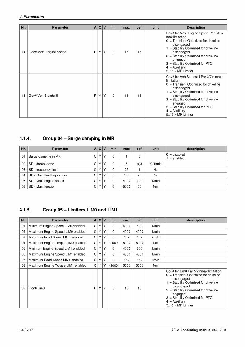
4. Parameters
34 / 207 ADM3 operating manual rev. 9.01
Nr. Parameter A C V min max def. unit Description
14 Gov# Max. Engine Speed P Y Y 0 15 15
Gov# for Max. Engine Speed Par 3/2 n max limitation 0 = Transient Optimized for driveline disengaged 1 = Stability Optimized for driveline disengaged 2 = Stability Optimized for driveline engaged 3 = Stability Optimized for PTO 4 = Auxiliary 5..15 = MR Limiter
15 Gov# Veh Standstill P Y Y 0 15 15
Gov# for Veh Standstill Par 3/7 n max limitation 0 = Transient Optimized for driveline disengaged 1 = Stability Optimized for driveline disengaged 2 = Stability Optimized for driveline engaged 3 = Stability Optimized for PTO 4 = Auxiliary 5..15 = MR Limiter
4.1.4. Group 04 – Surge damping in MR
Nr. Parameter A C V min max def. unit description
01 Surge damping in MR C Y Y 0 1 0 0 = disabled 1 = enabled
02 SD - droop factor C Y Y 0 5 0,3 %/1/min
03 SD - frequency limit C Y Y 0 25 1 Hz
04 SD - Max. throttle position C Y Y 0 100 25 %
05 SD - Max. engine speed C Y Y 0 4000 900 1/min
06 SD - Max. torque C Y Y 0 5000 50 Nm
4.1.5. Group 05 – Limiters LIM0 and LIM1
Nr. Parameter A C V min max def. unit description
01 Minimum Engine Speed LIM0 enabled C Y Y 0 4000 500 1/min
02 Maximum Engine Speed LIM0 enabled C Y Y 0 4000 4000 1/min
03 Maximum Road Speed LIM0 enabled C Y Y 0 152 152 km/h
04 Maximum Engine Torque LIM0 enabled C Y Y -2000 5000 5000 Nm
05 Minimum Engine Speed LIM1 enabled C Y Y 0 4000 500 1/min
06 Maximum Engine Speed LIM1 enabled C Y Y 0 4000 4000 1/min
07 Maximum Road Speed LIM1 enabled C Y Y 0 152 152 km/h
08 Maximum Engine Torque LIM1 enabled C Y Y -2000 5000 5000 Nm
09 Gov# Lim0 P Y Y 0 15 15
Gov# for Lim0 Par 5/2 nmax limitation 0 = Transient Optimized for driveline disengaged 1 = Stability Optimized for driveline disengaged 2 = Stability Optimized for driveline engaged 3 = Stability Optimized for PTO 4 = Auxiliary 5..15 = MR Limiter

4. Parameters
ADM3 operating manual rev. 9.01 35 / 207
Nr. Parameter A C V min max def. unit description
10 Gov# Lim1 P Y Y 0 15 15
Gov# for Lim1 Par 5/6 nmax limitation 0 = Transient Optimized for driveline disengaged 1 = Stability Optimized for driveline disengaged 2 = Stability Optimized for driveline engaged 3 = Stability Optimized for PTO 4 = Auxiliary 5..15 = MR Limiter
4.1.6. Group 06 – Limiters AC/LIM2
Nr. Parameter A C V min max def. unit description
03 Minimum Engine Speed LIM2 /KLIMA C Y Y 0 4000 500 1/min
04 Maximum Engine Speed LIM2 /KLIMA C Y Y 0 4000 4000 1/min
05 Maximum Road Speed LIM2 / KLIMA C Y Y 0 152 152 km/h
06 Maximum Engine Torque LIM2 / KLIMA C Y Y -2000 5000 5000 Nm
07 Limit Governor# Air Condition P Y Y 0 15 15
Gov# for LIM2/KLIMA Par 6/4 n max limitation 0 = Transient Optimized for driveline disengaged 1 = Stability Optimized for driveline disengaged 2 = Stability Optimized for driveline engaged 3 = Stability Optimized for PTO 4 = Auxiliary 5..15 = MR Limiter
4.1.7. Group 07 – PTO Control on PTO and CC pin
Nr. Parameter A C V min max def. unit description
01 Configuration PTO Speed Control C Y Y 0 4 0
0 = disabled 1 = enabled 2 = enabled if neutral 3 = enabled if neutral and park brake 4 = enabled if park brake
02 Maximum PTO Speed with CC+ Switch C Y Y 500 3000 3000 1/min
03 Minimum PTO Speed with CC- Switch C Y Y 500 3000 500 1/min
04 PTO Throttle Override Enable C Y Y 0 1 1 0 = Disable 1 = Enable engine speed in PTO mode to be increased with throttle input
05 Max. Engine Speed for Throttle Override C Y Y 0 3000 3000 1/min
06 PTO dropout on service brake or park brake enabled
C Y Y 0 3 0
0 = No PTO drop out with service brake or park brake enabled 1 = Causes PTO to drop out if the Service brake or the park brake is being depressed 2 = Drop out on service brake 3 = Drop out on park brake
07 PTO dropout on clutch enabled C Y Y 0 1 0 0 = No PTO drop out with clutch pedal 1 = Causes PTO to drop out if the clutch is being depressed
08 Maximum Road Speed in PTO Mode C Y Y 0 128 10 km/h
09 PTO Set Speed with CC- Switch C Y Y 0 3000 500 1/min
10 PTO Speed Governor Type with CC- Switch
S Y Y 1 11 1 Governor type selection, if PTO mode has been activated via CC-

4. Parameters
36 / 207 ADM3 operating manual rev. 9.01
Nr. Parameter A C V min max def. unit description
11 Max. PTO Torque with CC- Switch C Y Y 0 5000 5000 Nm
12 PTO Set Speed with CC+ Switch C Y Y 0 3000 500 1/min
13 PTO Speed Governor Type with CC+ Switch
S Y Y 1 11 1 Governor type selection, if PTO mode has been activated via CC+
14 Max. PTO Torque with CC+ Switch C Y Y 0 5000 5000 Nm
15 PTO Ramp Rate C Y Y 25 2500 1000 1/min/s
16 Number of Speeds via Remote PTO (Pin 18/10)
C Y Y 1 3 1
17 PTO Speed #1 C Y Y 500 3000 950 1/min
18 PTO Speed #1 Governor Type S Y Y 1 11 1 Governor type selection, if fixed speed #1 has been activated
19 PTO Speed #1 Maximum Engine Torque C Y Y 0 5000 5000 Nm
20 PTO Speed #2 C Y Y 500 3000 1250 1/min
21 PTO Speed #2 Governor Type S Y Y 1 11 1 Governor type selection, if fixed speed #2 has been activated
22 PTO Speed #2 Maximum Engine Torque C Y Y 0 5000 5000 Nm
23 PTO Speed #3 C Y Y 500 3000 1850 1/min
24 PTO Speed #3 Governor Type S Y Y 1 11 1 Governor type selection, if fixed speed #3 has been activated
25 PTO Speed #3 Maximum Engine Torque C Y Y 0 5000 5000 Nm
4.1.8. Group 08 – Vehicle Speed Sensor
Nr. Parameter A C V min max def. unit description
02 Vehicle Speed Sensor P Y Y 0 8 1
0 = none 1 = C3 from tachograph 2 = square wave (hall sensor) 3 = J1939 transmission 4 = inductive sensor 5 = J1939 TCO Shaft Speed and Vehicle Speed 6 = J1939 CC1, PGN65265 Vehicle Speed 7 = J1939 CC2, PGN65265 Vehicle Speed 8 = J1939 CC3, PGN65265 Vehicle Speed
03 Axle Ratio C Y Y 1 20 5,29
04 Number of Output Shaft Teeth C Y Y 0 250 16
05 Tire Revolutions per Kilometer C Y Y 160 1599 312 1/(km/h)
06 Top Gear Ratio C Y Y 0,1 2,55 1
07 Second Highest Gear Ratio C Y Y 0 5,75 2,55
08 Gear Ratio Tolerance C Y Y 0 60 2 1/min/MPH
09 Two Speed Axle - Second Axle Ratio C Y Y 1 20 5,29
15 No monitoring of vehicle speed sensor VSS
P Y Y 0 1 0 0 = monitoring active 1 = not active

4. Parameters
ADM3 operating manual rev. 9.01 37 / 207
4.1.9. Group 09 – Analog Outputs
Nr. Parameter A C V min max def. unit description
01 Configuration Analog Output (IWA) S Y Y 0 11 1
0 = disabled 1 = throttle torque 10..90% 2 = Difference torque (external load control) 3 = throttle torque 90..10% 4 = actual torque 5 = load torque (no idle torque for automatic transmission) 6 = road speed 7 = demand speed 8 = demand speed CC+/- 9 = AGS2 transmission Temp indication lamp off 10 = AGS2 transmiss. Temp indication lamp on 11 = AdBlue level 10..90%
02 Engine Speed Display N_Mot S Y Y 200 15000 2173 Scaling: Pulses per 100 rpm
03 Oil Pressure / Fuel Filter S Y Y 0 4 1
0 = lamp 1 = 5 bar cluster 2 = 10 bar cluster 3 = no sensor 4 = fuel filter sensor
04 Coolant Temperature / AGS2 Lamp S Y Y 0 5 1
0 = lamp 1 = cluster 3 = off (not used) 4 = reserved 5 = AGS2 check transmiss. indication lamp
4.1.10. Group 10 – Engine Brake
Nr. Parameter A C V min max def. unit description
01 Minimum Engine Speed for Engine Brakes S Y Y 0 4000 1100 1/min
02 Maximum Throttle Position for Engine Brakes
S Y Y 0 100 4 %
03 Enable Engine Brakes on Service Brake C Y Y 0 2 0
0 = disable 1 = engine brake on service brake, engine brake remains engaged 2 = engine brake on service brake
04 Minimum Road Speed for Engine Brake Operation
C Y Y 0 200 0 km/h
05 Enable Engine Brake on Road Speed Limiter
C Y Y 0 48 5 km/h
Engine brakes will come on automatically if vehicle exceeds entered value. 0 = engine brake disabled for overspeed
06 Engine Brakes and Cruise Control C Y Y 0 2 0
0 = no automatic engine brake on cruise control 1 = enable automatic engine brake operation with cruise control 2 = disable cruise control on engine rake
07 CC Eng. Brake 1 on S Y Y 0 48 5 km/h Maximum Cruise Control Over-Speed for Engine Brake 1
08 CC Eng. Brake 1 off S Y Y 0 48 2 km/h Minimum Cruise Control Over-Speed for Engine Brake 1
09 CC Eng. Brake 2 on S Y Y 0 48 7 km/h Maximum Cruise Control Over-Speed for Engine Brake 2
10 CC Eng. Brake 2 off S Y Y 0 48 5 km/h Minimum Cruise Control Over-Speed for Engine Brake 2
11 CC Eng. Brake 3 on S Y Y 0 48 10 km/h Maximum Cruise Control Over-Speed for Engine Brake 3
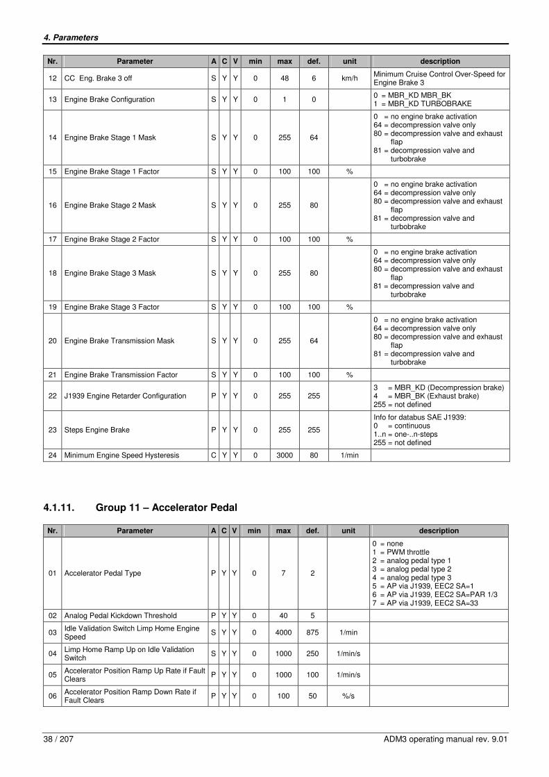
4. Parameters
38 / 207 ADM3 operating manual rev. 9.01
Nr. Parameter A C V min max def. unit description
12 CC Eng. Brake 3 off S Y Y 0 48 6 km/h Minimum Cruise Control Over-Speed for Engine Brake 3
13 Engine Brake Configuration S Y Y 0 1 0 0 = MBR_KD MBR_BK 1 = MBR_KD TURBOBRAKE
14 Engine Brake Stage 1 Mask S Y Y 0 255 64
0 = no engine brake activation 64 = decompression valve only 80 = decompression valve and exhaust flap 81 = decompression valve and turbobrake
15 Engine Brake Stage 1 Factor S Y Y 0 100 100 %
16 Engine Brake Stage 2 Mask S Y Y 0 255 80
0 = no engine brake activation 64 = decompression valve only 80 = decompression valve and exhaust flap 81 = decompression valve and turbobrake
17 Engine Brake Stage 2 Factor S Y Y 0 100 100 %
18 Engine Brake Stage 3 Mask S Y Y 0 255 80
0 = no engine brake activation 64 = decompression valve only 80 = decompression valve and exhaust flap 81 = decompression valve and turbobrake
19 Engine Brake Stage 3 Factor S Y Y 0 100 100 %
20 Engine Brake Transmission Mask S Y Y 0 255 64
0 = no engine brake activation 64 = decompression valve only 80 = decompression valve and exhaust flap 81 = decompression valve and turbobrake
21 Engine Brake Transmission Factor S Y Y 0 100 100 %
22 J1939 Engine Retarder Configuration P Y Y 0 255 255 3 = MBR_KD (Decompression brake) 4 = MBR_BK (Exhaust brake) 255 = not defined
23 Steps Engine Brake P Y Y 0 255 255
Info for databus SAE J1939: 0 = continuous 1..n = one-..n-steps 255 = not defined
24 Minimum Engine Speed Hysteresis C Y Y 0 3000 80 1/min
4.1.11. Group 11 – Accelerator Pedal
Nr. Parameter A C V min max def. unit description
01 Accelerator Pedal Type P Y Y 0 7 2
0 = none 1 = PWM throttle 2 = analog pedal type 1 3 = analog pedal type 2 4 = analog pedal type 3 5 = AP via J1939, EEC2 SA=1 6 = AP via J1939, EEC2 SA=PAR 1/3 7 = AP via J1939, EEC2 SA=33
02 Analog Pedal Kickdown Threshold P Y Y 0 40 5
03 Idle Validation Switch Limp Home Engine Speed
S Y Y 0 4000 875 1/min
04 Limp Home Ramp Up on Idle Validation Switch
S Y Y 0 1000 250 1/min/s
05 Accelerator Position Ramp Up Rate if Fault Clears
P Y Y 0 1000 100 1/min/s
06 Accelerator Position Ramp Down Rate if Fault Clears
P Y Y 0 100 50 %/s

4. Parameters
ADM3 operating manual rev. 9.01 39 / 207
Nr. Parameter A C V min max def. unit description
07 PWM Pedal Kickdown Switch On Threshold
C Y Y 0 40 4 %
08 PWM Pedal Kickdown Switch Off Threshold
C Y Y 0 40 11 %
09 Boost Thres. active C Y Y 0 1 0
10 Boost Thres ramp C Y Y 0 2000 300 Nm/10ms
11 acc.pedal characteristic x1 C Y Y 0 100 0 %
12 acc.pedal characteristic y1 C Y Y 0 100 0 %
13 acc.pedal characteristic x2 C Y Y 0 100 100 %
14 acc.pedal characteristic y2 C Y Y 0 100 100 %
15 acc.pedal characteristic x3 C Y Y 0 100 100 %
16 acc.pedal characteristic y3 C Y Y 0 100 100 %
17 acc.pedal characteristic x4 C Y Y 0 100 100 %
18 acc.pedal characteristic y4 C Y Y 0 100 100 %
20 pedal filter tau large signal range C Y Y 0,00 10,0 0,00 s
21 pedal filter tau small signal range C Y Y 0,00 10,0 0,00 s
22 pedal filter small signal range C Y Y 0 100 0 %
23 acc. pedal ramp up C Y Y 0 100 100 %/10ms
24 acc. pedal ramp down C Y Y 0 100 100 %/10ms
4.1.12. Group 12 – MAS & OI
Nr. Parameter A C V min max def. unit description
01 Maintenance Alert System P Y Y 0 1 0 0 = MAS disabled 1 = MAS enabled
04 CEL/SEL Delay After Ignition S Y Y 1 255 15 s Time duration after bulb check for CEL/SEL to flash at ignition on.
05 Level Fault CEL/SEL Flash Mode S Y Y 0 3 1 mode
Mode for CEL/SEL flashing for maintenance monitor level faults. 0 = none 1 = flash at ignition on 2 = CEL on continuously when fault active 3 = both
06 Filter Fault CEL/SEL Flash Mode S Y Y 0 3 2 mode
Mode for CEL/SEL flashing for maintenance monitor filter faults. 0 = none 1 = flash at ignition on 2 = CEL on continuously when fault active 3 = both
4.1.13. Group 13 – Inputs
Nr. Parameter A C V min max def. unit description
02 Coolant Level Sensor Input (KW_SE) P Y Y 0 1 0 0 = Disable 1 = ACTROS sensor
03 Enable Air Filter Sensor Input S Y Y 0 2 0 0 = no air filter 1 = MB-Air Filter 2 = DDC Air Filter Strategy
06 Configuration Service Brake P Y Y 0 4 1
0 = Disable 1 = service brake input 2 = CC1 service brake 3 = CC2 service brake 4 = CC3 service brake
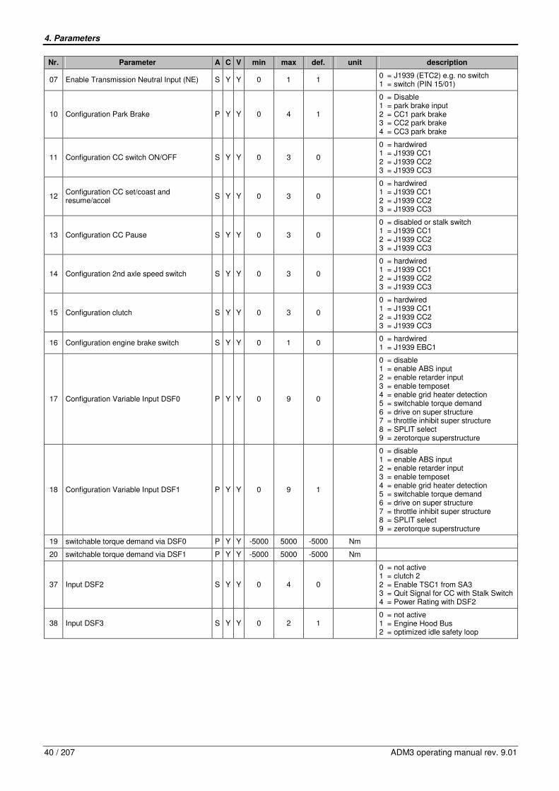
4. Parameters
40 / 207 ADM3 operating manual rev. 9.01
Nr. Parameter A C V min max def. unit description
07 Enable Transmission Neutral Input (NE) S Y Y 0 1 1 0 = J1939 (ETC2) e.g. no switch 1 = switch (PIN 15/01)
10 Configuration Park Brake P Y Y 0 4 1
0 = Disable 1 = park brake input 2 = CC1 park brake 3 = CC2 park brake 4 = CC3 park brake
11 Configuration CC switch ON/OFF S Y Y 0 3 0
0 = hardwired 1 = J1939 CC1 2 = J1939 CC2 3 = J1939 CC3
12 Configuration CC set/coast and resume/accel
S Y Y 0 3 0
0 = hardwired 1 = J1939 CC1 2 = J1939 CC2 3 = J1939 CC3
13 Configuration CC Pause S Y Y 0 3 0
0 = disabled or stalk switch 1 = J1939 CC1 2 = J1939 CC2 3 = J1939 CC3
14 Configuration 2nd axle speed switch S Y Y 0 3 0
0 = hardwired 1 = J1939 CC1 2 = J1939 CC2 3 = J1939 CC3
15 Configuration clutch S Y Y 0 3 0
0 = hardwired 1 = J1939 CC1 2 = J1939 CC2 3 = J1939 CC3
16 Configuration engine brake switch S Y Y 0 1 0 0 = hardwired 1 = J1939 EBC1
17 Configuration Variable Input DSF0 P Y Y 0 9 0
0 = disable 1 = enable ABS input 2 = enable retarder input 3 = enable temposet 4 = enable grid heater detection 5 = switchable torque demand 6 = drive on super structure 7 = throttle inhibit super structure 8 = SPLIT select 9 = zerotorque superstructure
18 Configuration Variable Input DSF1 P Y Y 0 9 1
0 = disable 1 = enable ABS input 2 = enable retarder input 3 = enable temposet 4 = enable grid heater detection 5 = switchable torque demand 6 = drive on super structure 7 = throttle inhibit super structure 8 = SPLIT select 9 = zerotorque superstructure
19 switchable torque demand via DSF0 P Y Y -5000 5000 -5000 Nm
20 switchable torque demand via DSF1 P Y Y -5000 5000 -5000 Nm
37 Input DSF2 S Y Y 0 4 0
0 = not active 1 = clutch 2 2 = Enable TSC1 from SA3 3 = Quit Signal for CC with Stalk Switch 4 = Power Rating with DSF2
38 Input DSF3 S Y Y 0 2 1 0 = not active 1 = Engine Hood Bus 2 = optimized idle safety loop
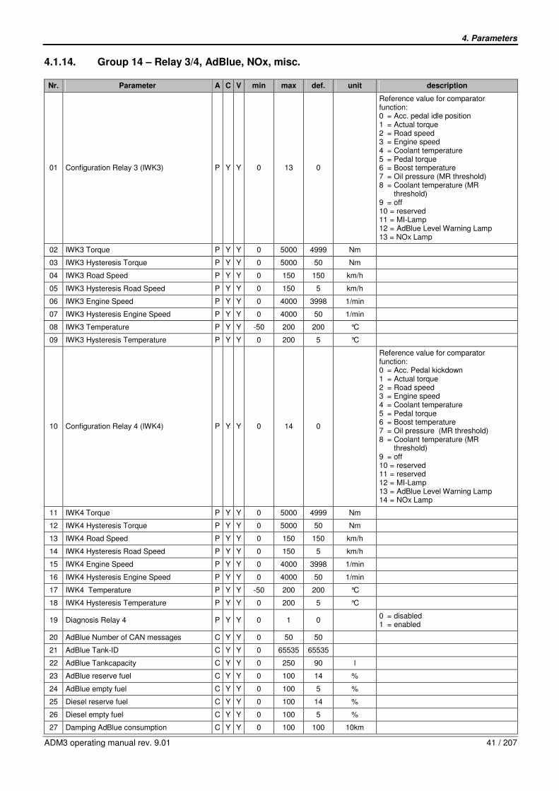
4. Parameters
ADM3 operating manual rev. 9.01 41 / 207
4.1.14. Group 14 – Relay 3/4, AdBlue, NOx, misc.
Nr. Parameter A C V min max def. unit description
01 Configuration Relay 3 (IWK3) P Y Y 0 13 0
Reference value for comparator function: 0 = Acc. pedal idle position 1 = Actual torque 2 = Road speed 3 = Engine speed 4 = Coolant temperature 5 = Pedal torque 6 = Boost temperature 7 = Oil pressure (MR threshold) 8 = Coolant temperature (MR threshold) 9 = off 10 = reserved 11 = MI-Lamp 12 = AdBlue Level Warning Lamp 13 = NOx Lamp
02 IWK3 Torque P Y Y 0 5000 4999 Nm
03 IWK3 Hysteresis Torque P Y Y 0 5000 50 Nm
04 IWK3 Road Speed P Y Y 0 150 150 km/h
05 IWK3 Hysteresis Road Speed P Y Y 0 150 5 km/h
06 IWK3 Engine Speed P Y Y 0 4000 3998 1/min
07 IWK3 Hysteresis Engine Speed P Y Y 0 4000 50 1/min
08 IWK3 Temperature P Y Y -50 200 200 °C
09 IWK3 Hysteresis Temperature P Y Y 0 200 5 °C
10 Configuration Relay 4 (IWK4) P Y Y 0 14 0
Reference value for comparator function: 0 = Acc. Pedal kickdown 1 = Actual torque 2 = Road speed 3 = Engine speed 4 = Coolant temperature 5 = Pedal torque 6 = Boost temperature 7 = Oil pressure (MR threshold) 8 = Coolant temperature (MR threshold) 9 = off 10 = reserved 11 = reserved 12 = MI-Lamp 13 = AdBlue Level Warning Lamp 14 = NOx Lamp
11 IWK4 Torque P Y Y 0 5000 4999 Nm
12 IWK4 Hysteresis Torque P Y Y 0 5000 50 Nm
13 IWK4 Road Speed P Y Y 0 150 150 km/h
14 IWK4 Hysteresis Road Speed P Y Y 0 150 5 km/h
15 IWK4 Engine Speed P Y Y 0 4000 3998 1/min
16 IWK4 Hysteresis Engine Speed P Y Y 0 4000 50 1/min
17 IWK4 Temperature P Y Y -50 200 200 °C
18 IWK4 Hysteresis Temperature P Y Y 0 200 5 °C
19 Diagnosis Relay 4 P Y Y 0 1 0 0 = disabled 1 = enabled
20 AdBlue Number of CAN messages C Y Y 0 50 50
21 AdBlue Tank-ID C Y Y 0 65535 65535
22 AdBlue Tankcapacity C Y Y 0 250 90 l
23 AdBlue reserve fuel C Y Y 0 100 14 %
24 AdBlue empty fuel C Y Y 0 100 5 %
25 Diesel reserve fuel C Y Y 0 100 14 %
26 Diesel empty fuel C Y Y 0 100 5 %
27 Damping AdBlue consumption C Y Y 0 100 100 10km

4. Parameters
42 / 207 ADM3 operating manual rev. 9.01
Nr. Parameter A C V min max def. unit description
28 Damping Diesel consumption C Y Y 0 100 100 10km
29 Damping AdBlue level C Y Y 0 250 60 s
31 Battery cutoff switch / GGVS C Y Y 0 3 0
0 = without Battery cutoff switch / GGVS 1 = with Battery cutoff switch / GGVS 2 = n.d. 3 = s.n.v.
32 NOx torque reduction P Y Y 0 255 60 % FDOK protected parameter!
34 Resistance 1 C Y Y 0 65535 65535 Ohm
35 Level 1 C Y Y 0 65535 65535 %
36 Resistance 2 C Y Y 0 65535 65535 Ohm
37 Level 2 C Y Y 0 65535 65535 %
38 Resistance 3 C Y Y 0 65535 65535 Ohm
39 Level 3 C Y Y 0 65535 65535 %
40 Resistance 4 C Y Y 0 65535 65535 Ohm
41 Level 4 C Y Y 0 65535 65535 %
42 Resistance 5 C Y Y 0 65535 65535 Ohm
43 Level 5 C Y Y 0 65535 65535 %
44 Resistance 6 C Y Y 0 65535 65535 Ohm
45 Level 6 C Y Y 0 65535 65535 %
46 Resistance 7 C Y Y 0 65535 65535 Ohm
47 Level 7 C Y Y 0 65535 65535 %
48 Resistance 8 C Y Y 0 65535 65535 Ohm
49 Level 8 C Y Y 0 65535 65535 %
50 Resistance 9 C Y Y 0 65535 65535 Ohm
51 Level 9 C Y Y 0 65535 65535 %
52 Resistance 10 C Y Y 0 65535 65535 Ohm
53 Level 10 C Y Y 0 65535 65535 %
54 Resistance 11 C Y Y 0 65535 65535 Ohm
55 Level 11 C Y Y 0 65535 65535 %
56 Resistance 12 C Y Y 0 65535 65535 Ohm
57 Level 12 C Y Y 0 65535 65535 %
58 Resistance 13 C Y Y 0 65535 65535 Ohm
59 Level 13 C Y Y 0 65535 65535 %
60 Resistance 14 C Y Y 0 65535 65535 Ohm
61 Level 14 C Y Y 0 65535 65535 %
62 Resistance 15 C Y Y 0 65535 65535 Ohm
63 Level 15 C Y Y 0 65535 65535 %
64 Resistance 16 C Y Y 0 65535 65535 Ohm
65 Level 16 C Y Y 0 65535 65535 %
66 Resistance 17 C Y Y 0 65535 65535 Ohm
67 Level 17 C Y Y 0 65535 65535 %
68 Resistance 18 C Y Y 0 65535 65535 Ohm
69 Level 18 C Y Y 0 65535 65535 %
70 Resistance 19 C Y Y 0 65535 65535 Ohm
71 Level 19 C Y Y 0 65535 65535 %
72 Lower faulty Resistance C Y Y 0 65535 65535 Ohm
73 Upper faulty Resistance C Y Y 0 65535 65535 Ohm
74 Diesel Tank Capacity C Y Y 0 5000 500 L

4. Parameters
ADM3 operating manual rev. 9.01 43 / 207
4.1.15. Group 15 – Cruise Control I
Nr. Parameter A C V min max def. unit description
01 Minimum Road Speed for Cruise Control C Y Y 38 152 48 km/h
02 Maximum Set Speed for Cruise Control C Y Y 48 152 152 km/h
03 Cruise Set Speed Increment P Y Y 0 10 2 km/h
04 Cruise Set Speed Decrement P Y Y 0 10 2 km/h
05 Cruise Set Speed Ramp Up P Y Y 0 20 2 km/h/s
06 Cruise Set Speed Ramp Down P Y Y 0 20 2 km/h/s
07 Enable Cruise Auto Resume C Y Y 0 2 0
0 = disable 1 = enable automatic cruise resume function after clutch has been released once 2 = release clutch twice
08 Min. Eng. Speed Cruise Control P Y Y 400 3000 800 1/min
16 Cruise Control Logic P Y Y 0 2 0 0 = FTL 1 = Hyundai 2 = Mitsubishi
4.1.16. Group 16 – Relay 1 / Starter Lockout
Nr. Parameter A C V min max def. unit description
01 Output Relay 1/Starter Lockout S Y Y 0 9 2
0 = disable 1 = enable starter lockout 2 = enable kick down output 3 = enable modulat. Relay Allison transm. 4 = reserved 5 = split valve 2 6 = starter lockout & AGS2 7 = MI-Lamp 8 = AdBlue Level Warning Lamp 9 = NOx Lamp
02 Starter Lockout Diagnosis P Y Y 0 1 0 Starter Lockout Open Load Diagnosis: 0 = enabled 1 = disabled
4.1.17. Group 17 – Idle/PTO Shutdown
Nr. Parameter A C V min max def. unit description
01 Enable Idle Shutdown C Y Y 0 3 0
0 = disable 1 = enable idle shutdown with Park Brake status 2 = enable idle shutdown without Park Brake status 3 = enable idle shutdown with edge triggered accelerator pedal
02 Idle Shutdown Time C Y Y 1 5000 60 s
03 Enable PTO Shutdown C Y Y 0 3 0
0 = disable 1 = enable PTO shutdown with Park Brake status 2 = enable PTO shutdown without Park Brake status 3 = enable PTO shutdown with edge triggered accelerator pedal
04 PTO Shutdown Time C Y Y 1 5000 60 s
05 Maximum Engine Load for PTO Shutdown S Y Y 0 5000 100 Nm
06 Time for CEL before Idle/PTO Shutdown P Y Y 3 120 20 s
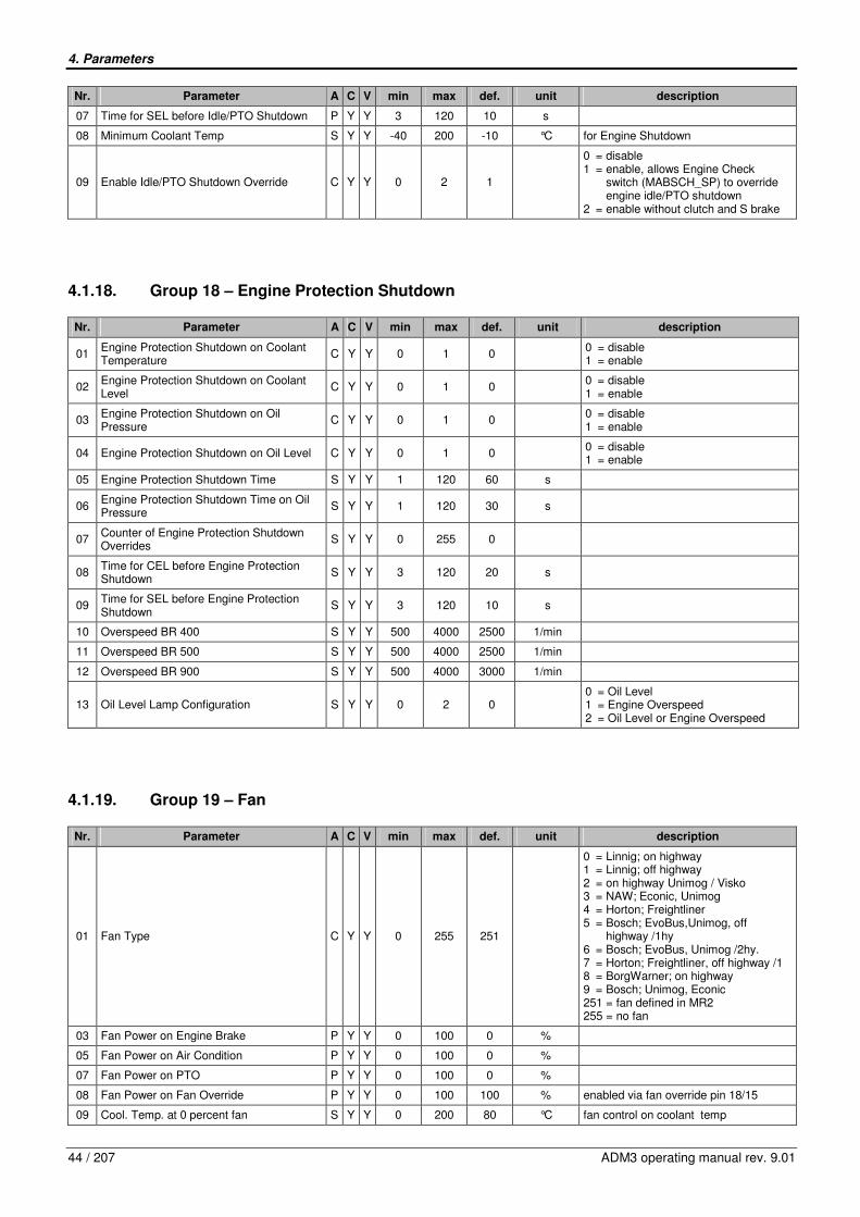
4. Parameters
44 / 207 ADM3 operating manual rev. 9.01
Nr. Parameter A C V min max def. unit description
07 Time for SEL before Idle/PTO Shutdown P Y Y 3 120 10 s
08 Minimum Coolant Temp S Y Y -40 200 -10 °C for Engine Shutdown
09 Enable Idle/PTO Shutdown Override C Y Y 0 2 1
0 = disable 1 = enable, allows Engine Check switch (MABSCH_SP) to override engine idle/PTO shutdown 2 = enable without clutch and S brake
4.1.18. Group 18 – Engine Protection Shutdown
Nr. Parameter A C V min max def. unit description
01 Engine Protection Shutdown on Coolant Temperature
C Y Y 0 1 0 0 = disable 1 = enable
02 Engine Protection Shutdown on Coolant Level
C Y Y 0 1 0 0 = disable 1 = enable
03 Engine Protection Shutdown on Oil Pressure
C Y Y 0 1 0 0 = disable 1 = enable
04 Engine Protection Shutdown on Oil Level C Y Y 0 1 0 0 = disable 1 = enable
05 Engine Protection Shutdown Time S Y Y 1 120 60 s
06 Engine Protection Shutdown Time on Oil Pressure
S Y Y 1 120 30 s
07 Counter of Engine Protection Shutdown Overrides
S Y Y 0 255 0
08 Time for CEL before Engine Protection Shutdown
S Y Y 3 120 20 s
09 Time for SEL before Engine Protection Shutdown
S Y Y 3 120 10 s
10 Overspeed BR 400 S Y Y 500 4000 2500 1/min
11 Overspeed BR 500 S Y Y 500 4000 2500 1/min
12 Overspeed BR 900 S Y Y 500 4000 3000 1/min
13 Oil Level Lamp Configuration S Y Y 0 2 0 0 = Oil Level 1 = Engine Overspeed 2 = Oil Level or Engine Overspeed
4.1.19. Group 19 – Fan
Nr. Parameter A C V min max def. unit description
01 Fan Type C Y Y 0 255 251
0 = Linnig; on highway 1 = Linnig; off highway 2 = on highway Unimog / Visko 3 = NAW; Econic, Unimog 4 = Horton; Freightliner 5 = Bosch; EvoBus,Unimog, off highway /1hy 6 = Bosch; EvoBus, Unimog /2hy. 7 = Horton; Freightliner, off highway /1 8 = BorgWarner; on highway 9 = Bosch; Unimog, Econic 251 = fan defined in MR2 255 = no fan
03 Fan Power on Engine Brake P Y Y 0 100 0 %
05 Fan Power on Air Condition P Y Y 0 100 0 %
07 Fan Power on PTO P Y Y 0 100 0 %
08 Fan Power on Fan Override P Y Y 0 100 100 % enabled via fan override pin 18/15
09 Cool. Temp. at 0 percent fan S Y Y 0 200 80 °C fan control on coolant temp

4. Parameters
ADM3 operating manual rev. 9.01 45 / 207
Nr. Parameter A C V min max def. unit description
10 Cool. Temp. at 100 percent fan S Y Y 0 200 100 °C
11 Hold time Fan P Y Y 0 600 10 s
12 Ramp Fan P Y Y 1 100 25 %/s
13 Fan Power on DSF0 P Y Y 0 100 50 % Selection of the percentage of the fan power consumption on DSF0
14 Fan Power on DSF1 P Y Y 0 100 50 % Selection of the percentage of the fan power consumption on DSF1
4.1.20. Group 20 – Remote Accelerator Pedal
Nr. Parameter A C V min max def. unit description
01 Enable Remote Accelerator Pedal Input S Y Y 0 1 0 0 = disable 1 = enable
02 Delay Time for Rem.Acc.Pedal Wide Open Calibration
P Y Y 0 5 1 s
03 Maximum Change of Remote Acc. Pedal Wide Open
P Y Y 0 15 1 %
04 Remote Accelerator Pedal Signal Filter Coefficient
P Y Y 0 1 0,5
05 Remote Accelerator Pedal Idle Position S Y Y 0 30 20 %
06 Remote Accelerator Pedal Wide Open Position
S Y Y 70 85 78 %
07 HFG Diagnostics Only With Active Pin “FG-Wahl”
S Y Y 0 1 1 0 = always 1 = only by active pin 18/7 throttle select
4.1.21. Group 21 – Droop Control Mode
Nr. Parameter A C V min max def. unit description
01 Droop Control Mode S Y Y 0 2 0 0 = disable 1 = without pedal tolerance 2 = with pedal tolerance
02 Droop Control Governor Type S Y Y 1 11 1
03 Droop Maximum Engine Torque S Y Y 0 5000 5000 Nm
4.1.22. Group 22 – TSC1 Limiter Governor (N max)
Nr. Parameter A C V min max def. unit description
01 Gov# TSC1 Transmission P Y Y 0 4 2 Gov# for TSC1 Transmission n max limitation
02 Gov# TSC1 ABS P Y Y 0 15 15 Gov# for TSC1 ABS n max limitation
03 Gov# TSC1 Jack Knife P Y Y 0 15 15 Gov# for TSC1 Jack Knife n max limitation
04 Gov# TSC1 ACC P Y Y 0 5 5 Gov# for TSC1 ACC n max limitation
20 Speed Gov# TSC1 condition #0 P Y Y 0 16 0 MR speed governor# which is used for TSC1 requested speed control condition #0. See J1939/71 SPN 696
21 Speed Gov# TSC1 condition #1 P Y Y 0 11 1 MR speed governor# which is used for TSC1 requested speed control condition #1. See J1939/71 SPN 696

4. Parameters
46 / 207 ADM3 operating manual rev. 9.01
Nr. Parameter A C V min max def. unit description
22 Speed Gov# TSC1 condition #2 P Y Y 0 11 2 MR speed governor# which is used for TSC1 requested speed control condition #2. See J1939/71 SPN 696
23 Speed Gov# TSC1 condition #3 P Y Y 0 11 3 MR speed governor# which is used for TSC1 requested speed control condition #3. See J1939/71 SPN 696
4.1.23. Group 23 – Limiters II
Nr. Parameter A C V min max def. unit description
01 Torque factor gear down protection S Y Y 0,00 1,00 1,00 Torque reduction factor in gears below the ratio that is set in parameter 23/2
02 Gear ratio for gear down protection S Y Y 0,000 2000 0,010 km/h/
(1/min)
Torque reduction occurs to gear ratios below this value. See also parameter 23/01
03 Torque factor high gear power S Y Y 0,00 1,00 1,00 Torque reduction factor in gears below the ratio that is set in parameter 23/4
04 Gear ratio for high gear power S Y Y 0,000 2000 0,020 km/h/
(1/min)
Torque reduction occurs to gear ratios below this value. See also parameter 23/03
06 Max engine speed for progressive shifting C Y Y 500 3000 3000 1/min Engine RPM is limited to this value when vehicle is in a gear ratio below the value set in 23/19. See also Parameter 23/07
07 Gear Ratio for Progressive Shifting C Y Y 0,000 2,000 0,015 km/h/
(1/min) Gear ratio at which 23/18 is affected. See also Parameter 23/06
08 AL Engine Speed Threshold S Y Y 10 500 50 1/min Upper-Speed limit := actual engine speed + engine-speed-threshold (Acceleration limiter)
09 AL Min. Engine Speed Threshold S Y Y 500 4000 1200 1/min Limitation enabled if actual engine speed is higher than Min. Engine Speed threshold (Acceleration limiter)
10 AL Ramp up Rate S Y Y 0 4000 160 (1/min)/s Acceleration limiter
11 AL Minimum Eng. Torque S Y Y 0 100 100 %
Minimum value of torque reduction in percent of maximum torque. To enable the function the parameter must be <100 % (Acceleration limiter)
12 AL Droop Parameter S Y Y 0,0 100,0 3,0 Nm/(1/min) Droop governor parameter (Acceleration limiter)
13 gear protection 1st speed P Y Y 0 150 0 km/h V < V1: engine torque limit
14 gear protection 2nd speed P Y Y 0 150 0 km/h V > V2: no limitation
15 gear protection, torque limitation P Y Y 0 5000 5000 Nm V < V1: torque limitation
4.1.24. Group 24 – Vehicle Parameters II
This group contains only not visible parameters.
4.1.25. Group 25 – XTempomat
This group contains only not visible parameters.
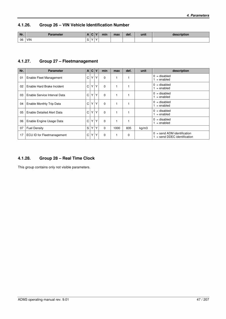
4. Parameters
ADM3 operating manual rev. 9.01 47 / 207
4.1.26. Group 26 – VIN Vehicle Identification Number
Nr. Parameter A C V min max def. unit description
06 VIN S Y Y
4.1.27. Group 27 – Fleetmanagement
Nr. Parameter A C V min max def. unit description
01 Enable Fleet Management C Y Y 0 1 1 0 = disabled 1 = enabled
02 Enable Hard Brake Incident C Y Y 0 1 1 0 = disabled 1 = enabled
03 Enable Service Interval Data C Y Y 0 1 1 0 = disabled 1 = enabled
04 Enable Monthly Trip Data C Y Y 0 1 1 0 = disabled 1 = enabled
05 Enable Detailed Alert Data C Y Y 0 1 1 0 = disabled 1 = enabled
06 Enable Engine Usage Data C Y Y 0 1 1 0 = disabled 1 = enabled
07 Fuel Density S Y Y 0 1000 835 kg/m3
17 ECU ID for Fleetmanagement C Y Y 0 1 0 0 = send ADM identification 1 = send DDEC identification
4.1.28. Group 28 – Real Time Clock
This group contains only not visible parameters.

4. Parameters
48 / 207 ADM3 operating manual rev. 9.01
4.2. Description of Parameters
4.2.1. Group 01 – CAN Configuration
CAN Configuration
Nr. Parameter Description
01 Engine CAN One Wire Capability (MCAN)
In accordance with the CAN definition, the CAN-High and CAN-Low data wires transmit the same information with complementary physical levels.
The CAN connection between the vehicle control ADM3 and the engine control PLD/MR2 provides a limp home routine. This allows communications to be continued on the second, intact wire in the event of a failure (short or broken circuit) in one wire.
One wire capability must be deactivated if more than two participants are connected to the engine CAN (parameter value 0).
Concerning the one wire capability, the vehicle control ADM3 and the engine control PLD/MR2 must have identical settings.
Parameter values: 1 = Two Wire Mode Only 0 = Enable One Wire Mode
02 Engine CAN Limp Home Mode
Response PLD/MR2 if engine CAN failure
Parameter values: 0 = idle speed (engine switches over to idle running) 1 = engine stop (engine will shut down) 2 = limp home speed (engine maintains actual speed or reduces the speed to a limp home speed, if it is currently exceeded) 3 = limp home speed (engine maintains actual speed or reduces the speed to a limp home speed, if it is currently exceeded)
Upon switching the engine off and on again, the engine adopts the limp home speed via a ramp, starting with the idle speed.
03 SAE J1939 3. Source Address TSC1 (e.g. jack knife protection)
Programmable source address of jack knife protection on SAE J1939 data bus.
04 SAE J1939 Source Address Motor
05 SAE J1939 Source Address Engine Brake
06 SAE J1939 Source Address Transmission
07 SAE J1939 Source Address ABS
08 SAE J1939 Source Transmission Retarder
09 SAE J1939 Source Address CC1
10 SAE J1939 Source Address CC2
11 SAE J1939 Source Address CC3
12 SAE J1939 Source Address EBC1
13
SAE J1939 Source Address Ambient Temperature
15
EBC1 direction for AGS2
Parameter values: 0 = receive EBC1 1 = transmit EBC1
16
Send Free Running Telegram on K line:
Parameter values: 0 = no FRT 1 = with FRT
Programmable source address of the respective participant on the data bus SAE J1939.
17
J1939 Timeout Detection
Parameter values: 0 = not active 1 = active
Activation of diagnosis for J1939 CAN signals.
Signals are checked for “Not defined” (FMI 19) and “Signal Not Available” (FMI 09), missing messages lead to FMI 09 for signals that are used for the current parameter configuration
18
SPN Conversion Method
Parameter values: 0 = 2 1 = 4
Conversion Method for SPNs as used in diagnostic messages DM1, DM2 and DM4
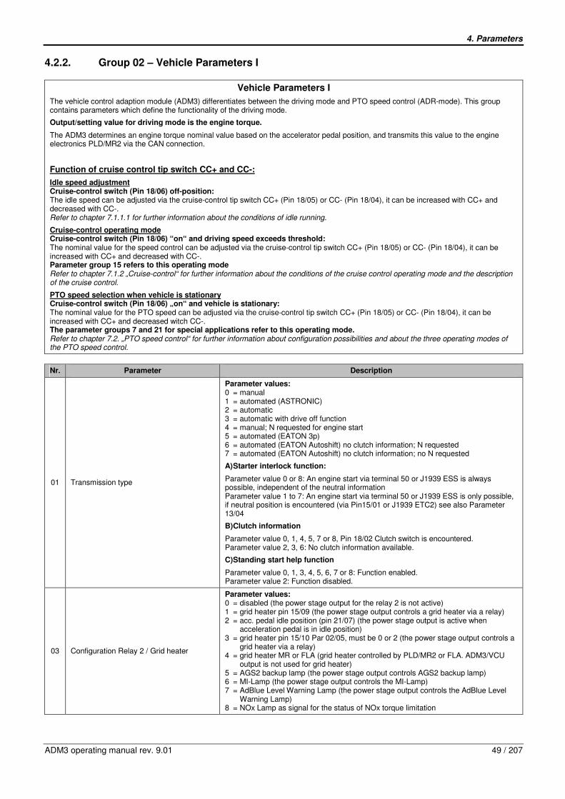
4. Parameters
ADM3 operating manual rev. 9.01 49 / 207
4.2.2. Group 02 – Vehicle Parameters I
Vehicle Parameters I
The vehicle control adaption module (ADM3) differentiates between the driving mode and PTO speed control (ADR-mode). This group contains parameters which define the functionality of the driving mode.
Output/setting value for driving mode is the engine torque.
The ADM3 determines an engine torque nominal value based on the accelerator pedal position, and transmits this value to the engine electronics PLD/MR2 via the CAN connection.
Function of cruise control tip switch CC+ and CC-:
Idle speed adjustment Cruise-control switch (Pin 18/06) off-position: The idle speed can be adjusted via the cruise-control tip switch CC+ (Pin 18/05) or CC- (Pin 18/04), it can be increased with CC+ and decreased with CC-. Refer to chapter 7.1.1.1 for further information about the conditions of idle running.
Cruise-control operating mode Cruise-control switch (Pin 18/06) “on“ and driving speed exceeds threshold: The nominal value for the speed control can be adjusted via the cruise-control tip switch CC+ (Pin 18/05) or CC- (Pin 18/04), it can be increased with CC+ and decreased with CC-. Parameter group 15 refers to this operating mode Refer to chapter 7.1.2 „Cruise-control“ for further information about the conditions of the cruise control operating mode and the description of the cruise control.
PTO speed selection when vehicle is stationary Cruise-control switch (Pin 18/06) „on“ and vehicle is stationary: The nominal value for the PTO speed can be adjusted via the cruise-control tip switch CC+ (Pin 18/05) or CC- (Pin 18/04), it can be increased with CC+ and decreased witch CC-. The parameter groups 7 and 21 for special applications refer to this operating mode. Refer to chapter 7.2. „PTO speed control“ for further information about configuration possibilities and about the three operating modes of the PTO speed control.
Nr. Parameter Description
01 Transmission type
Parameter values: 0 = manual 1 = automated (ASTRONIC) 2 = automatic 3 = automatic with drive off function 4 = manual; N requested for engine start 5 = automated (EATON 3p) 6 = automated (EATON Autoshift) no clutch information; N requested 7 = automated (EATON Autoshift) no clutch information; no N requested
A) Starter interlock function:
Parameter value 0 or 8: An engine start via terminal 50 or J1939 ESS is always possible, independent of the neutral information Parameter value 1 to 7: An engine start via terminal 50 or J1939 ESS is only possible, if neutral position is encountered (via Pin15/01 or J1939 ETC2) see also Parameter 13/04
B) Clutch information
Parameter value 0, 1, 4, 5, 7 or 8, Pin 18/02 Clutch switch is encountered. Parameter value 2, 3, 6: No clutch information available.
C) Standing start help function
Parameter value 0, 1, 3, 4, 5, 6, 7 or 8: Function enabled. Parameter value 2: Function disabled.
03 Configuration Relay 2 / Grid heater
Parameter values: 0 = disabled (the power stage output for the relay 2 is not active) 1 = grid heater pin 15/09 (the power stage output controls a grid heater via a relay) 2 = acc. pedal idle position (pin 21/07) (the power stage output is active when acceleration pedal is in idle position) 3 = grid heater pin 15/10 Par 02/05, must be 0 or 2 (the power stage output controls a grid heater via a relay) 4 = grid heater MR or FLA (grid heater controlled by PLD/MR2 or FLA. ADM3/VCU output is not used for grid heater) 5 = AGS2 backup lamp (the power stage output controls AGS2 backup lamp) 6 = MI-Lamp (the power stage output controls the MI-Lamp) 7 = AdBlue Level Warning Lamp (the power stage output controls the AdBlue Level Warning Lamp) 8 = NOx Lamp as signal for the status of NOx torque limitation
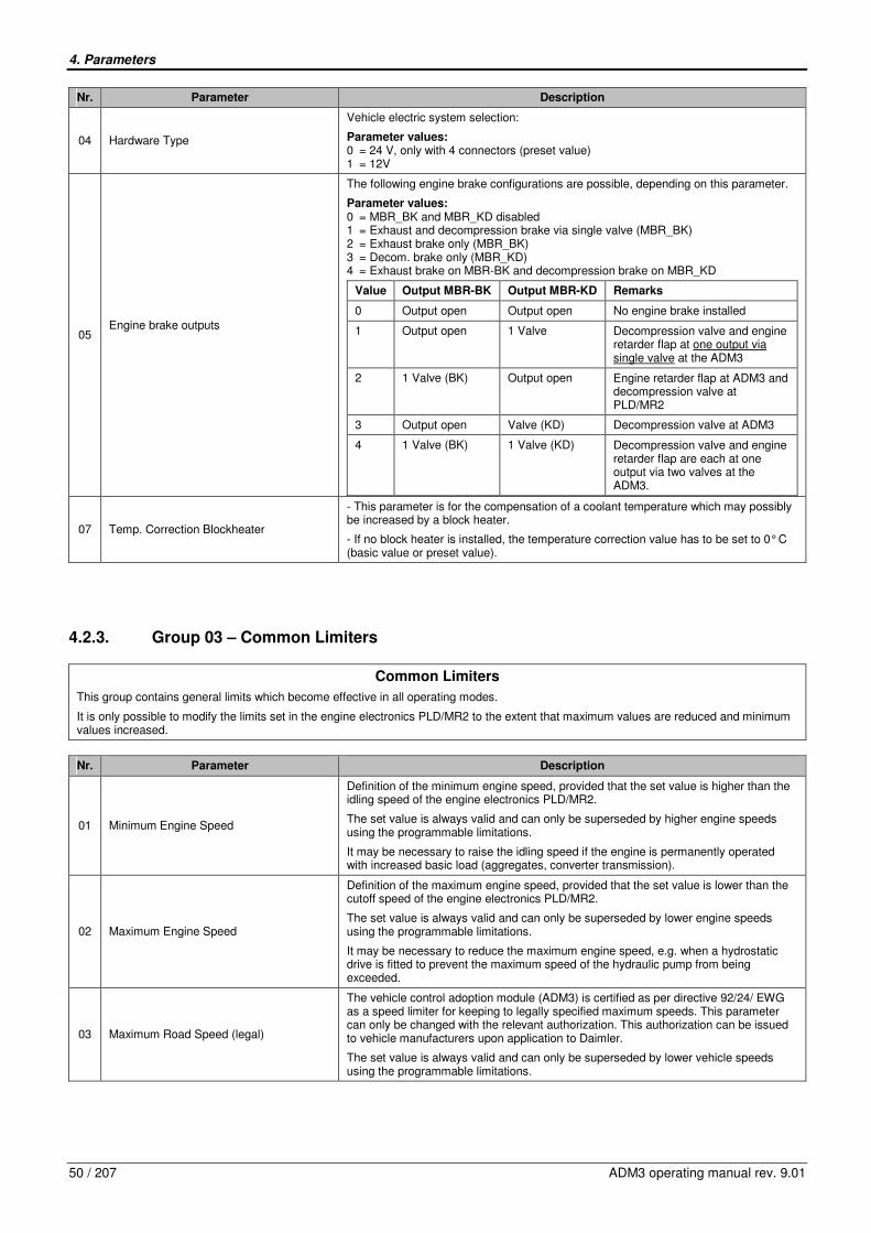
4. Parameters
50 / 207 ADM3 operating manual rev. 9.01
Nr. Parameter Description
04 Hardware Type
Vehicle electric system selection:
Parameter values: 0 = 24 V, only with 4 connectors (preset value) 1 = 12V
05 Engine brake outputs
The following engine brake configurations are possible, depending on this parameter.
Parameter values: 0 = MBR_BK and MBR_KD disabled 1 = Exhaust and decompression brake via single valve (MBR_BK) 2 = Exhaust brake only (MBR_BK) 3 = Decom. brake only (MBR_KD) 4 = Exhaust brake on MBR-BK and decompression brake on MBR_KD
Value Output MBR-BK Output MBR-KD Remarks
0 Output open Output open No engine brake installed
1 Output open 1 Valve Decompression valve and engine retarder flap at one output via single valve at the ADM3
2 1 Valve (BK) Output open Engine retarder flap at ADM3 and decompression valve at PLD/MR2
3 Output open Valve (KD) Decompression valve at ADM3
4 1 Valve (BK) 1 Valve (KD) Decompression valve and engine retarder flap are each at one output via two valves at the ADM3.
07 Temp. Correction Blockheater
- This parameter is for the compensation of a coolant temperature which may possibly be increased by a block heater.
- If no block heater is installed, the temperature correction value has to be set to 0° C (basic value or preset value).
4.2.3. Group 03 – Common Limiters
Common Limiters
This group contains general limits which become effective in all operating modes.
It is only possible to modify the limits set in the engine electronics PLD/MR2 to the extent that maximum values are reduced and minimum values increased.
Nr. Parameter Description
01 Minimum Engine Speed
Definition of the minimum engine speed, provided that the set value is higher than the idling speed of the engine electronics PLD/MR2.
The set value is always valid and can only be superseded by higher engine speeds using the programmable limitations.
It may be necessary to raise the idling speed if the engine is permanently operated with increased basic load (aggregates, converter transmission).
02 Maximum Engine Speed
Definition of the maximum engine speed, provided that the set value is lower than the cutoff speed of the engine electronics PLD/MR2.
The set value is always valid and can only be superseded by lower engine speeds using the programmable limitations.
It may be necessary to reduce the maximum engine speed, e.g. when a hydrostatic drive is fitted to prevent the maximum speed of the hydraulic pump from being exceeded.
03 Maximum Road Speed (legal)
The vehicle control adoption module (ADM3) is certified as per directive 92/24/ EWG as a speed limiter for keeping to legally specified maximum speeds. This parameter can only be changed with the relevant authorization. This authorization can be issued to vehicle manufacturers upon application to Daimler.
The set value is always valid and can only be superseded by lower vehicle speeds using the programmable limitations.

4. Parameters
ADM3 operating manual rev. 9.01 51 / 207
Nr. Parameter Description
04 Maximum Engine Torque
Limitation of the maximum torque value, provided that the set value is below the maximum torque value of the engine electronics PLD/MR2.
The set value is always valid and can only be superseded by lower torques using the programmable limitations.
05 Enable Limiting Torque Ramp
Accelerator Pedal delaying on vehicle stand still.
Parameter values: 0 = disable (limiting Torque Ramp is not active) 1 = enable (limiting Torque Ramp is activated)
06 Limiting Torque Ramp Increment Accelerator Pedal delay rate on vehicle stand still.
07 Engine Speed Limit while Vehicle stop While vehicle stop the engine speed is limited to the value which has been defined here
08 Desired Idle Speed Single Step Increase/Decrease
Idle-speed can be adjusted with the cruise-control tip switch CC+ (Pin 18/05) or CC- (Pin 18/04) and with the cruise-control switch (Pin18/06) is in the off position. This parameter determines the step size, which applies to both cruisecontrol tip switches and is of the same size when increasing with CC+ and decreasing with CC-
09 Desired Idle Speed Ramp Rate Increase/Decrease
This parameter indicates the ramp, with which the idle-speed is adjusted when the tip switches are activated continuously.
10 Maximum Adjusted Idle Speed Upper final value of idle speed adjustment.
11 Max. Road Speed for Idle Increase/Decrease
Limit speed of the vehicle, up to which the idle-speed adjustment is enabled.
13 Maximum Torque Engine Retarder Maximum engine brake torque.
14 Governor Maximum Engine Speed
Parameter values 0..4 used PI-Governor.
Parameter values: 0 = Transient Optimized for driveline disengaged 1 = Stability Optimized for driveline disengaged 2 = Stability Optimized for driveline engaged 3 = Stability Optimized for PTO 4 = Auxiliary 5 .. 15 = MR Limiter
15 Governor Vehicle Standstill
Parameter values 0..4 used PI-Governor.
Parameter values: 0 = Transient Optimized for driveline disengaged 1 = Stability Optimized for driveline disengaged 2 = Stability Optimized for driveline engaged 3 = Stability Optimized for PTO 4 = Auxiliary 5 .. 15 = MR Limiter
4.2.4. Group 04 – Surge damping in MR
Surge damping PLD/MR2
Nr. Parameter Description
01 Surge damping in MR
The damper of engine jerking is switched on with this parameter.
Parameter values: 0 = disabled 1 = enabled
� Adjustment of parameters 04/01 until 04/06 only in driving test and only through skilled workers with know-how in control engineering.
02 SD - droop factor
This parameter indicates the gain of the governor for the damper of engine jerking.
� Adjustment of parameters 04/01 until 04/06 only in driving test and only through skilled workers with know-how in control engineering
03 SD - frequency limit
This parameter indicates the frequency limit of the governor for the damper of engine jerking.
� Adjustment of parameters 04/01 until 04/06 only in driving test and only through skilled workers with know-how in control engineering

4. Parameters
52 / 207 ADM3 operating manual rev. 9.01
Nr. Parameter Description
04 SD - Max. throttle position
This parameter indicates the maximum position of the accelerator pedal for the damper of engine jerking.
� Adjustment of parameters 04/01 until 04/06 only in driving test and only through skilled workers with know-how in control engineering.
05 SD - Max. engine speed
This parameter indicates the maximum speed for the damper of engine jerking.
� Adjustment of parameters 04/01 until 04/06 only in driving test and only through skilled workers with know-how in control engineering.
06 SD - Max. torque
This parameter indicates the maximum torque for the damper of engine jerking.
� Adjustment of parameters 04/01 until 04/06 only in driving test and only through skilled workers with know-how in control engineering.
4.2.5. Group 05 – Limiters LIM0 and LIM1
Limiters LIM0 and LIM1
These limitations become effective depending on the switching state of the digital inputs LIM0 (limit 0) or LIM1 (limit 1).
The limitations are effective in the driving mode as well as in the PTO speed control (ADR-mode). The effective limit values result from a minimum value generation based on the upper limit values and a maximum value generation based on the lower limit values of PLD/MR2 internal limit values.
Limit values of the parameter group 03 (common limiters) and limit values of the parameter group 05 and 06 (variable limiters)
Nr. Parameter Description
01 Minimum Engine Speed LIM0 Definition of idle speed increase. The set value is selected via input LIM0 (limit 0).
02 Maximum Engine Speed LIM0 Definition of engine speed limitation. The set value is selected via input LIM0 (limit 0).
03 Maximum Road Speed LIM0 Definition of a reduced maximum speed. The set value is selected via input LIM0 (limit 0).
04 Maximum Engine Torque LIM0 Definition of torque limitation. The set value is selected via input LIM0 (limit 0).
05 Minimum Engine Speed LIM1 Definition of idle speed increase. The set value is selected via input LIM1 (limit1).
06 Maximum Engine Speed LIM1 Definition of engine speed limitation. The set value is selected via input LIM1 (limit 1).
07 Maximum Road Speed LIM1 Definition of a reduced maximum speed. The set value is selected via input LIM1 (limit 1).
08 Maximum Engine Torque LIM1 Definition of torque limitation. The set value is selected via input LIM1 (limit 1).
09 Governor LIM0 (Gov# for Lim0 Par5/2 nmax limitation)
Parameter values 0..4 used PI-Governor.
Parameter values: 0 = Transient Optimized for driveline disengaged 1 = Stability Optimized for driveline disengaged 2 = Stability Optimized for driveline engaged 3 = Stability Optimized for PTO 4 = Auxiliary 5 .. 15 = MR Limiter
10 Governor LIM1 (Gov# for Lim1 Par5/6 nmax limitation)
Parameter values 0..4 used PI-Governor.
Parameter values: 0 = Transient Optimized for driveline disengaged 1 = Stability Optimized for driveline disengaged 2 = Stability Optimized for driveline engaged 3 = Stability Optimized for PTO 4 = Auxiliary 5 .. 15 = MR Limiter

4. Parameters
ADM3 operating manual rev. 9.01 53 / 207
4.2.6. Group 06 – Limiters AC/LIM2
Limiters AC/LIM2
These limitations become effective depending on the switching state of the digital input „KLIMA" (limit 2).
The limitations are effective in the driving mode as well as in the PTO speed control (ADR-operation).
The effective limit values result from a minimum value generation based on the upper limit values and a maximum value generation based on the lower limit values of PLD/MR2 internal limit values.
Limit values of the parameter group 03 (general limits) and limit values of the parameter group 05 and 06 (variable limits)
Nr. Parameter Description
03 Minimum Engine Speed LIM2 / KLIMA Definition of an idling speed increase. The set value is selected via input KLIMA (limit 2), air conditioner.
04 Maximum Engine Speed LIM2 / KLIMA Definition of engine speed limitation. The set value is selected via input KLIMA (limit 2), air conditioner.
05 Maximum Road Speed LIM2 / KLIMA Definition of a reduced maximum speed. The set value is selected via input KLIMA (limit 2), air conditioner.
06 Maximum Engine Torque LIM2 / KLIMA Definition of torque limitation. The set value is selected via input KLIMA (limit 2), air conditioner.
07 Limit Governor# Air Condition
Parameter values 0..4 used PI-Governor.
Parameter values: 0 = Transient Optimized for driveline disengaged 1 = Stability Optimized for driveline disengaged 2 = Stability Optimized for driveline engaged 3 = Stability Optimized for PTO 4 = Auxiliary 5 .. 15 = MR Limiter

4. Parameters
54 / 207 ADM3 operating manual rev. 9.01
4.2.7. Group 07 – PTO Control on PTO and CC pin
PTO Control on PTO and CC pin
This group contains parameters which define the functionality of the PTO speed control.
The PTO speed control is used for power take-offs, working equipment (e.g. cranes, piste maintenance equipment, harvesters etc.) and for stationary applications (e.g. compressors, power generators, pumps, etc.).
Output- or setting value for PTO-mode is a nominal engine speed.
The nominal engine speed is determined by the ADM3 and transmitted to the engine electronics PLD/MR2 via the CAN connection.
There are three different operating modes in the PTO-mode: - Driver’s cab – PTO - PTO with fixed speeds via PTO switch - Driving with PTO with special applications
Driver’s cab - PTO (parameter 01 to 05)
Cruise-control switch (Pin 18/06) ON and vehicle is stationary: The nominal value for the PTO speed can be adjusted via the cruise-control tip switch CC+ (Pin 18/05) or CC- (Pin 18/04). It can be increased with CC+ and decreased with CC-.
Refer to chapter 7.2.1.1 for information on configuration
PTO with fixed speeds via the PTO switch (parameter 16 to 25)
Up to three preset fixed speeds can be activated via the PTO Switch (Pin 18/10).
An initial switch-on activates a PTO speed control with the fixed speed 1. If it is switched off and shortly after switched on again (less than 1 second), the nominal speed value is set to the next nominal speed, fixed speed 2. Fixed speed 3 can be selected in the same way and thereupon it can be switched over to fixed speed 1. The PTO speed control is switched off, as soon as the PTO switch is for more than one second in the OFF position.
The operating mode PTO via PTO switch has priority over the driver’s cab PTO via the CC tip switches
Refer to chapter 7.2.1.2 for information on configuration.
Driving with PTO with special applications (see parameter group 21)
This operating mode enables driving in the speed-controlled operation (RQV-mode).
Refer to chapter 7.2.1.3 for information on configuration.
Nr. Parameter Description
01 Configuration PTO Speed Control
Parameter values: 0 = disabled (PTO speed control is disabled) 1 = enabled (PTO speed control is enabled) 2 = enabled if neutral (PTO speed control is only enabled as long as the transmission is in neutral position) 3 = enabled if neutral and park brake (PTO speed control is only enabled as long as the transmission is in neutral position and the parking brake is closed) 4 = enabled if park brake (PTO speed control is only enabled as long as the parking brake is closed)
02 Maximum PTO Speed with CC+ Switch Maximum speed, which can be achieved for the PTO speed control when the nominal speed is increased via the cruise control tip switch CC+
03 Minimum PTO Speed with CC- Switch Minimum speed, which can be achieved for the PTO mode when the nominal speed is decreased via the cruise control tip switch CC
04 PTO Throttle Override Enable
This parameter indicates, if the engine speed in the PTO mode can be enabled to be increased with the throttle input
Parameter values: 0 = Disable 1 = Enable engine speed in PTO mode to be increased with throttle input
05 Max. Engine Speed for Throttle Override This parameter indicates the maximum speed when the accelerator pedal is actuated in PTO-mode.
06 PTO dropout on service brake or park brake enabled
This parameter indicates if the PTO is caused to drop out when the service brake or the park brake is actuated.
Parameter values: 0 = No PTO drop out with service brake or park brake enabled 1 = Causes PTO to drop out if the service brake or the park brake is being depressed 2 = Drop out on service brake 3 = Drop out on park brake

4. Parameters
ADM3 operating manual rev. 9.01 55 / 207
Nr. Parameter Description
07 PTO dropout on clutch enabled
This parameter defines, if the PTO is caused to drop out when the clutch is being depressed.
Parameter values: 0 = No PTO drop out with clutch pedal 1 = Causes PTO to drop out if the clutch is being depressed
08 Maximum Road Speed in PTO Mode Maximum road speed, up to which a PTO mode is possible
09 PTO Set Speed with CC- Switch Starting speed, if PTO mode has been activated via CC-
10 PTO Speed Governor Type with CC- Switch
Governor type selection, if PTO mode has been activated via CC-
11 Maximum PTO Torque with CC- Switch Maximum torque, if PTO mode has been activated via CC-
12 PTO Set Speed with CC+ Switch Starting speed, if PTO mode has been activated via CC+
13 PTO Speed Governor Type with CC+ Switch
Governor type selection, if PTO mode has been activated via CC+
14 Maximum PTO Torque with CC+ Switch Maximum torque, if PTO mode has been activated via CC-+
15 PTO Ramp Rate In PTO mode, a new engine speed will be achieved over a ramp
16 Number of Speeds via Remote PTO (Pin 18/10)
Number of fixed speeds when activating the PTO speed control via the PTO switch:
Parameter values: 1 = one fixed speed can be selected Parameters 07/17 to 07/19 are effective 2 = two fixed speeds can be selected Parameters 07/17 to 07/22 are effective 3 = three fixed speed can be selected Parameters 07/17 to 07/25 are effective
(the generally valid and variable limits and the limits of the PLD/MR2 remain effective)
17 PTO Speed #1 Programmable speed value for fixed speed #1
18 PTO Speed #1 Governor Type Governor type selection, if fixed speed #1 has been activated
19 PTO Speed #1 Maximum Engine Torque Maximum engine torque, if fixed speed #1 has been activated
20 PTO Speed #2 Programmable speed value for fixed speed #2
21 PTO Speed #2 Governor Type Governor type selection, if fixed speed #2 has been activated
22 PTO Speed #2 Maximum Engine Torque Maximum engine torque, if fixed speed #2 has been activated
23 PTO Speed #3 Programmable speed value for fixed speed #3
24 PTO Speed #3 Governor Type Governor selection, if fixed speed #3 has been activated
25 PTO Speed #3 Maximum Engine Torque Maximum engine torque, if fixed speed #3 has been activated
4.2.8. Group 08 – Vehicle Speed Sensor
Vehicle Speed Sensor
This group contains the speed determination parameters.
To implement a speed limitation, the ADM3 requires a speed signal. Refer to chapter 7.8 „tachograph“ for further information about the function „speed signal“.
The parameter group 22 „speed sensor” only becomes active with the corresponding configuration of the parameter group 08 for either square-wave sensor (if parameter 08/01 with the value=2) or for SAE J1939 data bus (if parameter 08/ 01 with the value=3).
Nr. Parameter Description
02 Vehicle Speed Sensor
This parameter defines whether a speed signal is present, and if so what type. This value can only be changed with the relevant authorization. Such authorization can be issued to vehicle manufacturers upon application to Daimler.
Parameter values: 0 = none (disabled, no speed signal, e.g. for stationary operation) 1 = C3 from tachograph 2 = square wave (hall sensor) 3 = J1939 transmission (Transmission output shaft speed via SAE J1939 ETC1 (output shaft speed), PGN 61442) 4 = inductive sensor 5 = J1939 TCO Shaft Speed and Vehicle Speed 6 = J1939 CC1, PGN65265 Vehicle Speed 7 = J1939 CC2, PGN65265 Vehicle Speed 8 = J1939 CC3, PGN65265 Vehicle Speed
03 Axle Ratio Axle ration of rear axle.
04 Number of Output Shaft Teeth Number of output shaft teeth.

4. Parameters
56 / 207 ADM3 operating manual rev. 9.01
Nr. Parameter Description
05 Tire Revolutions per Kilometer Tire revolutions per kilometer.
06 Top Gear Ratio Top gear ratio of the transmission. It is used for the speed limitation in the case of a defective sensor.
07 Second Highest Gear Ratio Ratio of road speed to engine speed for second highest gear of the transmission.
08 Gear Ratio Tolerance Tolerance on second highest gear.
09 Two Speed Axle - Second Axle Ratio 2nd
gear ratio.
15 No monitoring of vehicle speed sensor VSS
0 = monitoring active (Vehicle speed sensor open wire detection enabled) 1 = not active (Vehicle speed sensor open wire detection disabled)
4.2.9. Group 09 – Analog Outputs
Analog Outputs
Nr. Parameter Description
01
Configuration Analog Output (IWA)
Refer to chapter 7.7 for further information about the function IWA
Parameter values: 0 = disabled 1 = throttle torque 10..90% 2 = Difference torque (external load control) 3 = throttle torque 90..10% 4 = actual torque 5 = load torque (no idle torque for automatic transmission) 6 = road speed 7 = demand speed 8 = demand speed CC+/- 9 = AGS2 transmission Temp indication lamp off 10 = AGS2 transmiss. Temp indication lamp on 11 = AdBlue level 10 – 90%
The physical value output at IWA can be selected. Pulse duty factors < 5% and >95% are evaluated as faults or as signal failures by the subsequent electronic circuit connected.
Value Meaning Remarks
0
1 Throttle torque (10% .. 90%)
Indication of accelerator pedal position idle - full throttle to 10 % .. 90 % pulse duty factor.
2 Differential torque (limit load signal)
Signal for engine load evaluation e.g. for limit load control 90%: Maximum engine torque reached (drive) 50%: Engine not under load 10%: Maximum friction torque reached
3 Throttle torque inverted (10% .. 90%)
Indication of accelerator pedal position idle - full throttle to 90 % .. 10 % pulse duty factor.
4 Actual torque Indication of the actual engine torque 0 .. Mdmax to 10 % .. 90% pulse duty factor
5 Load signal
Load signal for coupling an automatic transmission with PWM interface. Output value is the minimum of the active torque and set torque, which is calculated on the basis of a maximum value generation of the accelerator pedal demand and the cruise control demand
6 Road speed
Formation of an C3 signal for other electronics.
]ms[
1000*45,0]km/h[
FZGt
v =
t = periodic time of signal (with T = 2ms = constant = pulse period)
7 Nominal speed Indication of the currently active nominal speed during PTO mode to 10% .. 90% pulse duty factor
8 Demand speed CC +/-
Special function for crawler-vehicles. Cruise control function with CC+ / CC- Demand speedoutput on pin 12/05
9
AGS2 transmission temp indication lamp off
10
AGS2 transmission temp indication lamp on
11 AdBlue Level Indication of the AdBlue tank level. 10% PWM = AdBlue tank is empty 90% PWM = AdBlue tank is full

4. Parameters
ADM3 operating manual rev. 9.01 57 / 207
Nr. Parameter Description
02 Engine Speed Display N_MOT
A square-wave signal which is directly proportional to the engine speed is available at the N-MOT output. Pulse duty factor approx. 50%. The scaling, i.e. correlation of frequency to engine speed can be adjusted.
6000
][min]Hz[
1
MOT
MOT
−
=n
kf
fMOT : Frequency at output N_MOT k : Impulse number tachometer, number of impulses per 100 revolutions nMOT: Current engine speed, actual value
03 Oil Pressure / Fuel Filter
Configuration of the output P_OEL (oil pressure), according to the analog oil pressure display.
Parameter values: 0 = lamp (Warning lamp is connected to the output) 1 = 5 bar cluster (Analog 5 bar display connected):
Oil pressure [bar] Reference resistance [Ohm]
0 10
1 48
2 82
3 116
4 151
5 184
2 = 10 bar cluster (Analog 10 bar display connected):
Oil pressure [bar] Reference resistance [Ohm]
0 10
2 52
4 88
6 124
8 155
10 184
3 = no sensor 4 = fuel filter sensor
04 Coolant Temperature / AGS2 Lamp
Configuration of the output T_MOT (coolant temperature) according to the connected analog coolant-temperature display.
Parameter values: 0 = lamp (Warning lamp connected to the output) 1 = cluster (Analog display connected):
Temperature [C°] Reference resistance [Ohm]
40 287,4
60 134
80 69,1
100 38,5
120 22,7
3 = off (not used) 4 = reserved 5 = AGS2 check transmiss. Indication lamp

4. Parameters
58 / 207 ADM3 operating manual rev. 9.01
4.2.10. Group 10 – Engine Brake
Engine brake
This group contains parameters which define the characteristics and the function of an engine brake intervention. Refer to chapter 7.5 “Engine brake / ABS / Retarder” for further information about the function “Engine Brake”.
Risk of injury!
The engine brake is a safety-relevant function for commercial vehicles.
Incorrect or unsuitable parameter programming can make it impossible to actuate the engine brake. The lack of, or reduction in, engine braking power could lead to the vehicle brake being overloaded.
Changes to the parameters in this group must only be performed by specially trained personnel or after consultation with the engine manufacturer.
It is not normally necessary to change these parameters.
Nr. Parameter Description
01 Minimum Engine Speed for Engine Brakes An intervention of the engine brake is only possible, if the engine speed is above the speed which has been set here. This prevents the engine from being stopped by the engine brake intervention at excessively low speed.
02 Maximum Throttle Position for Engine Brakes (MBR)
This parameter indicates the maximum position of the accelerator pedal (as a percentage of the complete deflection of the accelerator pedal), where the engine brake is still controlled.
03 Enable Engine Brakes on Service Brake
This parameter specifies, if the engine brake is activated by the service brake.
Parameter values: 0 = disable 1 = engine brake on service brake, engine brake remains engaged 2 = engine brake on service brake
04 Minimum Road Speed for Engine Brake Operation
The intervention of the engine brake is only enabled, if the vehicle speed is above the vehicle speed which has been set here.
05 Enable Engine Brake on Road Speed Limiter
Engine brakes will be automatically activated, if vehicle speed exceeds set speed threshold. This parameter indicates the speed threshold.
0 km/h = engine brake disabled for overspeed (function deactivated)
06 Engine Brakes and Cruise Control
Engine brake will be automatically activated, if vehicle speed exceeds Cruise Control set speed.
Parameter values: 0 = no automatic engine brake on cruise control (function deactivated) 1 = enable automatic engine brake operation with cruise control 2 = disable cruise control on engine rake
07 Cruise Control Engine Brake 1 on (MBR_L On)
08 Cruise Control Engine Brake 1 off (MBR_L Off)
09 Cruise Control Engine Brake 2 on (MBR_H On)
10 Cruise control Engine Brake 2 off (MBR_H Off)
Cut in and cut off speeds (threshold values) for the engine brake step 1 (MBR_L) and 2 (MBR_H). In this case the parameter values are differential speeds referred to the set speed of the cruise control.
11 Cruise Control Engine Brake 3 on (both MBR_H and MBR_L on)
Cut in and cut off speeds (threshold values) for the engine brake step 3 (MBR_L and MBR_H).
12 Cruise Control Engine Brake 3 off (both MBR_H and MBR_L off)
Cut in and cut off speeds (threshold values) for the engine brake step 3 (MBR_L and MBR_H).
13 Engine Brake Configuration
Type of engine brake system
Parameter values: 0 = compression brake and exhaust flap 1 = compression brake and turbo brake

4. Parameters
ADM3 operating manual rev. 9.01 59 / 207
Nr. Parameter Description
14 Engine Brake Stage 1 Mask
Engine brake activation if MBR_L=1 and MBR_H=0
Parameter values: 0 = no activation 64 = decompression valve (stage1) 80 = decompression valve and exhaust flap (stage 2) 81 = decompression valve, exhaust flap and turbo brake (stage 3)
15 Engine Brake stage 1 Factor
Turbo brake torque demand relative value
If parameter 10/14 = 81 then parameter 10/15 can be set from 0 to 100% for turbo brake demand else parameter 10/15 has to be set on value 100%
16 Engine Brake Stage 2 Mask
Engine brake activation if MBR_L=0 and MBR_H=1
Parameter values: 0 = no activation 64 = decompression valve (stage 1) 80 = decompression valve and exhaust flap (stage 2) 81 = decompression valve ,exhaust flap and turbo brake (stage 3)
17 Engine Brake Stage 2 Factor
Turbo brake torque demand relative value
If parameter 10/16 = 81 then parameter 10/17 can be set from 0 to 100% for turbo brake demand else parameter 10/17 has to be set on value 100%
18 Engine Brake Stage 3 Mask
Engine brake activation if MBR_L=1 and MBR_H=1
Parameter values: 0 = no activation 64 = decompression valve (stage 1) 80 = decompression valve and exhaust flap (stage 2) 81 = decompression valve ,exhaust flap and turbo brake (stage 3)
19 Engine Brake Stage 3 Factor
Turbo brake torque demand relative to value
If parameter 10/18 = 81 then parameter 10/19 can be set from 0 to 100% for turbo brake demand else parameter 10/19 has to be set on value 100%
20 Engine Brake Transmission Mask
Engine brake activation via J1939 TSC1 from transmission
Parameter values: 0 = no activation 64 = decompression valve (stage 1) 80 = decompression valve and exhaust flap (stage 2) 81 = decompression valve ,exhaust flap and turbo brake (stage 3)
21 Engine Brake Transmission Factor
Turbo brake torque demand relative value
If parameter 10/20 = 81 then parameter 10/21 can be set from 0 to 100% for turbo brake demand else parameter 10/21 has to be set on value 100%
22 J1939 Engine Retarder Configuration
refer to standard SAE 1939 chapter 5.2.2.2 and chapter 5.2.2.3
Parameter values: 3 = MBR_KD (constantly open valve) 4 = MBR_BK (engine retarder flap) 255 = not defined
23 Steps Engine Brake
For databus SAE J1939:
Parameter values: 0 = continuous 1..n = one-..n-steps 255 = not defined
24 Minimum Engine Speed Hysteresis Minimum Engine speed hysteresis

4. Parameters
60 / 207 ADM3 operating manual rev. 9.01
4.2.11. Group 11 – Accelerator Pedal
Accelerator pedal
This group contains parameters which define the evaluation of the accelerator pedal. Refer to chapter 7.3 „Accelerator Pedal/Remote accelerator pedal“ for further information about the function „accelerator pedal“.
Risk of injury!
The accelerator pedal is a safety-relevant function for commercial vehicles. Incorrect or unsuitable parameter programming can seriously affect the reactions of the accelerator pedal. This can cause the driver’s requirements (e.g. throttle back) not to be implemented properly or only after a delay.
Changes to the parameters in this group must only be performed by specially trained personnel or after consultation with the engine manufacturer. It is not normally necessary to change these parameters.
Nr. Parameter Description
01 Accelerator Pedal Type
In general the accelerator pedal serves for the transfer of the driver’s requirements to the engine.
Parameter values: 0 = not available (system without accelerator pedal Evaluation and monitoring of the FFG-signals are deactivated) 1 = PWM FFG (PWM accelerator pedal activated, e.g. VDO-Sensor) 2 = analog FFG type 1 (analog accelerator pedal activated, e.g. Williams-Pedal) 3 = analog FFG type 2 (analog accelerator pedal activated) 4 = analog FFG type 3 (analog accelerator pedal activated) 5 = SAE J1939 EEC2, SA =1 6 = SAE J1939 EEC2, SA =Par. 1/2 7 = SAE J1939 EEC2, SA =33
02 Analog pedal Kickdown Threshold Definition of the accelerator pedal position of the analog FFG below which (as a percentage of the complete deflection) the status „kickdown“ is set. The reference point (0%) is the maximum limit stop of the accelerator pedal.
03 Idle validation Switch Limp Home Engine Speed
The limp home speed, which the engine adopts in the case of an accelerator pedal failure. The limp home operating mode becomes effective, if the analogue value adopts implausible values, but the idle validation switches do still adopt plausible conditions.
04 Limp Home Ramp Up on Idle Validation Switch
Speed ramp for the transition from normal operation to limp home operating mode
05 Accelerator Position Ramp Up Rate if Fault Clears
Speed ramp for the transition from limp home operating mode to normal operation
06 Accelerator Position Ramp Down Rate if Fault Clears
Release via a ramp, if the FFG fault clears
07 PWM Pedal Kickdown Switch On Threshold
Definition of the accelerator pedal position of the PWM FFG below which (as a percentage of the complete deflection) the status „kickdown“ is set. The reference point (0%) is the maximum limit stop of the accelerator pedal.
08 PWM Pedal Kickdown Switch Off Threshold
Definition of the accelerator pedal position of the PWM FFG above which (as a percentage of the complete deflection) the status „kickdown“ is switched off. The reference point (0%) is the maximum limit stop of the accelerator pedal.
09 Boost Threshold active
10 Boost Threshold Ramp
11 acc.pedal characteristic x1
12 acc.pedal characteristic y1
13 acc.pedal characteristic x2
14 acc.pedal characteristic y2
15 acc.pedal characteristic x3
16 acc.pedal characteristic y3
17 acc.pedal characteristic x4
18 acc.pedal characteristic x4
20 pedal filter tau large signal range The parameters 11/20 to 11/22 are the filters for the signal changes of the accelerator
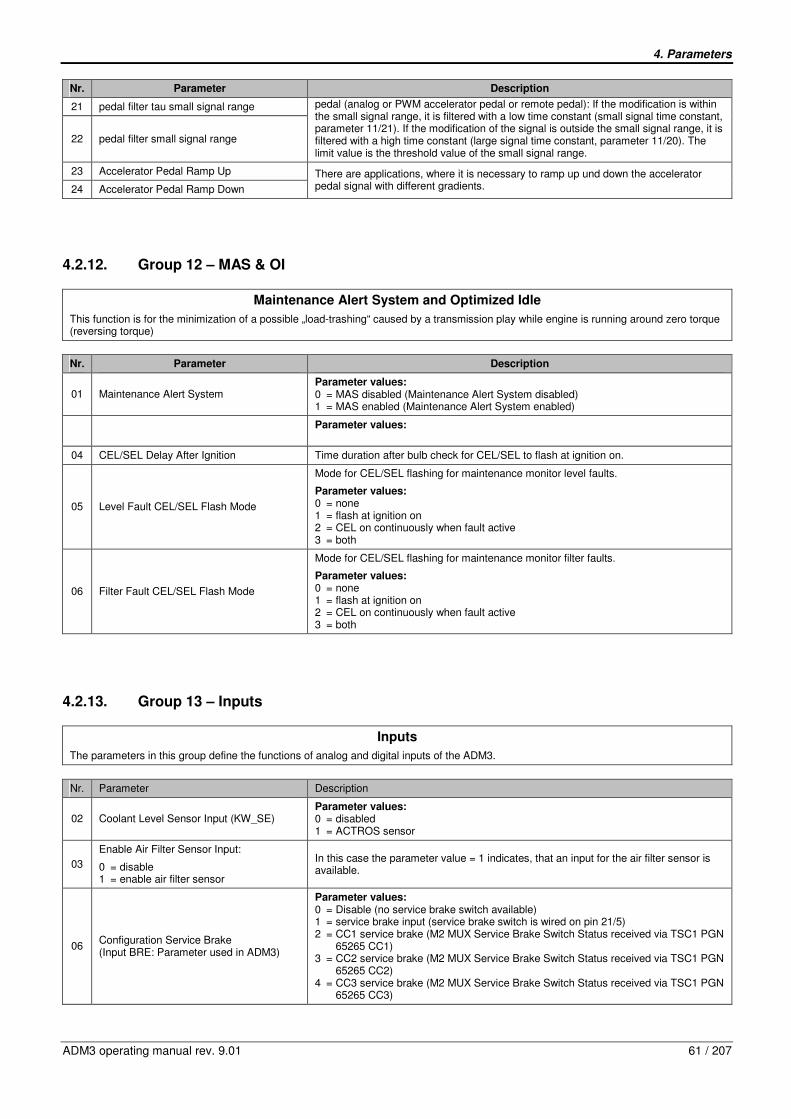
4. Parameters
ADM3 operating manual rev. 9.01 61 / 207
Nr. Parameter Description
21 pedal filter tau small signal range
22 pedal filter small signal range
pedal (analog or PWM accelerator pedal or remote pedal): If the modification is within the small signal range, it is filtered with a low time constant (small signal time constant, parameter 11/21). If the modification of the signal is outside the small signal range, it is filtered with a high time constant (large signal time constant, parameter 11/20). The limit value is the threshold value of the small signal range.
23 Accelerator Pedal Ramp Up
24 Accelerator Pedal Ramp Down
There are applications, where it is necessary to ramp up und down the accelerator pedal signal with different gradients.
4.2.12. Group 12 – MAS & OI
Maintenance Alert System and Optimized Idle
This function is for the minimization of a possible „load-trashing“ caused by a transmission play while engine is running around zero torque (reversing torque)
Nr. Parameter Description
01 Maintenance Alert System Parameter values: 0 = MAS disabled (Maintenance Alert System disabled) 1 = MAS enabled (Maintenance Alert System enabled)
Parameter values:
04 CEL/SEL Delay After Ignition Time duration after bulb check for CEL/SEL to flash at ignition on.
05 Level Fault CEL/SEL Flash Mode
Mode for CEL/SEL flashing for maintenance monitor level faults.
Parameter values: 0 = none 1 = flash at ignition on 2 = CEL on continuously when fault active 3 = both
06 Filter Fault CEL/SEL Flash Mode
Mode for CEL/SEL flashing for maintenance monitor filter faults.
Parameter values: 0 = none 1 = flash at ignition on 2 = CEL on continuously when fault active 3 = both
4.2.13. Group 13 – Inputs
Inputs
The parameters in this group define the functions of analog and digital inputs of the ADM3.
Nr. Parameter Description
02 Coolant Level Sensor Input (KW_SE) Parameter values: 0 = disabled 1 = ACTROS sensor
03
Enable Air Filter Sensor Input:
0 = disable 1 = enable air filter sensor
In this case the parameter value = 1 indicates, that an input for the air filter sensor is available.
06 Configuration Service Brake (Input BRE: Parameter used in ADM3)
Parameter values: 0 = Disable (no service brake switch available) 1 = service brake input (service brake switch is wired on pin 21/5) 2 = CC1 service brake (M2 MUX Service Brake Switch Status received via TSC1 PGN 65265 CC1) 3 = CC2 service brake (M2 MUX Service Brake Switch Status received via TSC1 PGN 65265 CC2) 4 = CC3 service brake (M2 MUX Service Brake Switch Status received via TSC1 PGN 65265 CC3)

4. Parameters
62 / 207 ADM3 operating manual rev. 9.01
Nr. Parameter Description
07
Enable Transmission Neutral Input (Input NE J1939 ETC2)
In this case the parameter value1= indicates, that an input for the sensing of the neutral position of the transmission is available.
Parameter values: 0 = J1939 (ETC2) e.g. no switch (neutral information is read from J1939, ETC1, Byte 4) 1 = switch (PIN 15/01) (neutral information is read from Pin 15/01)
10 Configuration Park Brake:
Parameter values: 0 = disable 1 = park brake input 2 = CC1 park brake 3 = CC2 park brake 4 = CC3 park brake
11 Configuration CC Switch ON/OFF
Parameter values: 0 = hardwired 1 = J1939 CC1 2 = J1939 CC2 3 = J1939 CC3
12 Configuration CC set/coast and resume/accelerate
Parameter values: 0 = hardwired 1 = J1939 CC1 2 = J1939 CC2 3 = J1939 CC3
13 Configuration CC Pause
Parameter values: 0 = disabled or stalk switch 1 = J1939 CC1 2 = J1939 CC2 3 = J1939 CC3
14 Configuration 2nd Axle Speed Switch
Parameter values: 0 = hardwired 1 = J1939 CC1 2 = J1939 CC2 3 = J1939 CC3
15 Configuration Clutch
Parameter values: 0 = hardwired 1 = J1939 CC1 2 = J1939 CC2 3 = J1939 CC3
16 Configuration Engine Brake Switch Parameter values: 0 = hardwired 1 = J1939 EBC1

4. Parameters
ADM3 operating manual rev. 9.01 63 / 207
Nr. Parameter Description
17
Configuration Variable Input DSF0
Refer to chapter 7 for further information about the function of ABS, Retarder, Temposet and grid heater.
Parameter values: 0 = Disable 1 = Enable ABS Input 2 = Enable Retarder Input 3 = Enable Temposet 4 = Enable grid heater monitoring 5 = switchable torque demand 6 = Drive on super structure 7 = Throttle inhibit super structure 8 = SPLIT select 9 = zerotorque super structure
Depending on the setting of this parameter, certain functions are activated with the high side digital input DSF0 (special function 0)
Value Meaning Remarks
0 Input DSF0 not active
1 ABS intervention DSF0 is available for coupling of conventional ABS control unit. When input DSF0 is active, the engine brake outputs are deactivated.
2 Retarder intervention
The input DSF0 is available for coupling a conventional retarder. When input DSF0 is active, the information „Retarder intervention“ is transmitted to the engine control PLD/MR2. This setting only has a useful purpose on units on which the fan is controlled via the engine control PLD/MR2.
3 Temposet
The input DSF0 is available for setting and deleting a temporary maximum speed. The temposet speed is also deleted when actuating the kickdown.
4 Monitoring Grid Heater
The input DSF0 monitors the function of the grid heater.
5 Switchable torque demand
If the switch DSF0 is actuated, as much torque is demanded from the engine as set in parameter 13/08. (Application e.g. with harvesters, in order to demand a maximum torque when harvesting, without having to install an accelerator pedal (FFG)).
6 Super Structure
Drive on super structure. Setting of the addresses in the CAN SAE J1939: super structure engine on address 1 and driving engine on address 0 (preset value). Switch-over from accelerator pedal (FFG) in the bottom carriage to the FFG in the super structure by actuating the switch DSF0. Now it is possible to accelerate the driving engine with the FFG in the super structure by actuating the switch DSF0.
7 Throttle inhibit super structure
If the switch is actuated, then accelerator pedal signal is only directed to IWA and relay 3 and 4. For IWA see: actual value output, pin 12/05 and parameter 09/01 values 1, 3, 7 and 8. For relay 3 see parameter 14/01 (value = 5). For relay 4 see parameter 14/10 (value = 5). If switch is actuated, all other functions are not supported with accelerator pedal signal, e.g. driving mode is disabled.
8 SPLIT select SPLIT switch.
9 Zerotorque superstructure

4. Parameters
64 / 207 ADM3 operating manual rev. 9.01
Nr. Parameter Description
18
Configuration Variable Input DSF1
Parameter values: 0 = Disable 1 = Enable ABS Input 2 = Enable Retarder Input 3 = Enable Temposet 4 = Enable grid heater monitoring 5 = switcheable torque 6 = Drive on super structure 7 = Throttle inhibit super structure 8 = SPLIT select 9 = zerotorque super structure
select Depending on this parameter certain functions are activated with the low side digital input DSF1(special function 1).
Value Meaning Remarks
0 Input DSF1 not active
1 ABS intervention
The input DSF1 is available for coupling a conventional ABS control unit. The engine brake outputs are deactivated if the output DSF0 is active
2 Retarder intervention
The input DSF1 is available for coupling a conventional retarder. When input DSF1 is active, the. information „Retarder intervention“ is transmitted to the engine control PLD/MR2. This setting only has a useful purpose on units on which the fan is controlled via the engine control PLD/MR2.
3 Temposet
The input DSF1 is available for setting and deleting a temporary maximum speed. The temposet speed is also deleted when actuating the kickdown. actuating the kickdown.
4 Monitoring Grid Heater
The input DSF1 monitors the function of r the grid heater.
5 Switcheable Torque Demand
5 If the switch DSF1 is actuated, as much torque is demanded from the engine as set in the parameter 13/09. (Application e.g. with harvesters, in order to demand a maximum torque when harvesting, without having to install an accelerator pedal (FFG)
6 Super Structure
Drive on super structure. Setting of the addresses in the CAN SAE J1939: super structure engine on address 1 and driving engine on address 0 (preset value). Switch-over from accelerator pedal (FFG) in the bottom carriage to the FFG in the super structure by actuating the switch DSF1. Now it is possible to accelerate the driving engine with the FFG in the super structure by actuating the switch DSF1.
7 Throttle inhibit super structure
If the switch is actuated, then accelerator pedal signal is only directed to IWA and relay 3 and 4. For IWA see: actual value output, pin 12/05 and parameter 09/01 values 1, 3, 7 and 8. For relay 3 see parameter 14/01 (value = 5). For relay 4 see parameter 14/10 (value = 5). If switch is actuated, all other functions are not supported with accelerator pedal signal, e.g. driving mode is disabled.
8 SPLIT select SPLIT switch.
9 Zerotorque superstructure
19 Switchable torque demand via DSF0 Parameter to set torque demand value, which is used if Parameter 13/06 is set to value 5 and digital input DSF0 is active.
20 Switchable torque demand via DSF1 Parameter to set torque demand value, which is used if Parameter 13/07 is set to value 5 and digital input DSF1 is active.
37 Input DSF2
Parameter values: 0 = not active 1 = clutch2 2 = Enable TSC1 from SA3 3 = Quit Signal for CC with Stalk Switch (please keep in mind, that the stalk switch functionality is activated only by setting this parameter value) 4 = Power Rating with DSF2
38 Input DSF3
Parameter values: 0 = not active 1 = Engine Hood Bus 2 = optimized idle safety loop
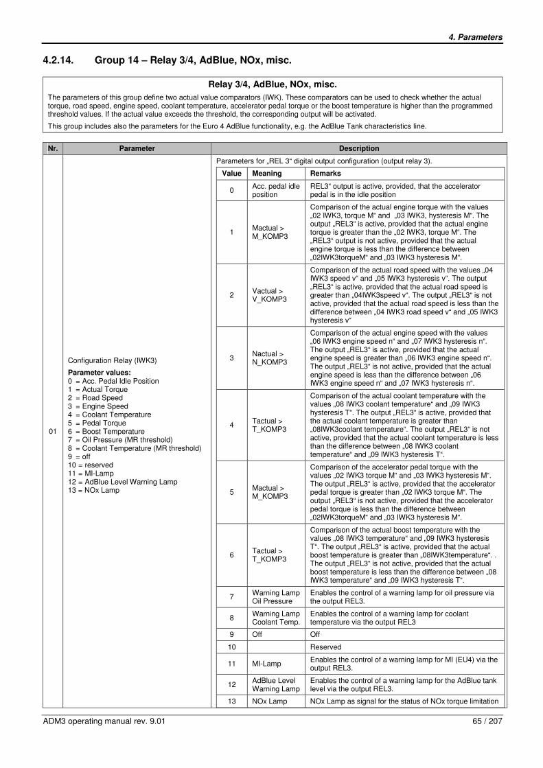
4. Parameters
ADM3 operating manual rev. 9.01 65 / 207
4.2.14. Group 14 – Relay 3/4, AdBlue, NOx, misc.
Relay 3/4, AdBlue, NOx, misc.
The parameters of this group define two actual value comparators (IWK). These comparators can be used to check whether the actual torque, road speed, engine speed, coolant temperature, accelerator pedal torque or the boost temperature is higher than the programmed threshold values. If the actual value exceeds the threshold, the corresponding output will be activated.
This group includes also the parameters for the Euro 4 AdBlue functionality, e.g. the AdBlue Tank characteristics line.
Nr. Parameter Description
01
Configuration Relay (IWK3)
Parameter values: 0 = Acc. Pedal Idle Position 1 = Actual Torque 2 = Road Speed 3 = Engine Speed 4 = Coolant Temperature 5 = Pedal Torque 6 = Boost Temperature 7 = Oil Pressure (MR threshold) 8 = Coolant Temperature (MR threshold) 9 = off 10 = reserved 11 = MI-Lamp 12 = AdBlue Level Warning Lamp 13 = NOx Lamp
Parameters for „REL 3“ digital output configuration (output relay 3).
Value Meaning Remarks
0 Acc. pedal idle position
REL3“ output is active, provided, that the accelerator pedal is in the idle position
1 Mactual > M_KOMP3
Comparison of the actual engine torque with the values „02 IWK3, torque M“ and „03 IWK3, hysteresis M“. The output „REL3“ is active, provided that the actual engine torque is greater than the „02 IWK3, torque M“. The „REL3“ output is not active, provided that the actual engine torque is less than the difference between „02IWK3torqueM“ and „03 IWK3 hysteresis M“.
2 Vactual > V_KOMP3
Comparison of the actual road speed with the values „04 IWK3 speed v“ and „05 IWK3 hysteresis v“. The output „REL3“ is active, provided that the actual road speed is greater than „04IWK3speed v“. The output „REL3“ is not active, provided that the actual road speed is less than the difference between „04 IWK3 road speed v“ and „05 IWK3 hysteresis v“
3 Nactual > N_KOMP3
Comparison of the actual engine speed with the values „06 IWK3 engine speed n“ and „07 IWK3 hysteresis n“. The output „REL3“ is active, provided that the actual engine speed is greater than „06 IWK3 engine speed n“. The output „REL3“ is not active, provided that the actual engine speed is less than the difference between „06 IWK3 engine speed n“ and „07 IWK3 hysteresis n“.
4 Tactual > T_KOMP3
Comparison of the actual coolant temperature with the values „08 IWK3 coolant temperature“ and „09 IWK3 hysteresis T“. The output „REL3“ is active, provided that the actual coolant temperature is greater than „08IWK3coolant temperature“. The output „REL3“ is not active, provided that the actual coolant temperature is less than the difference between „08 IWK3 coolant temperature“ and „09 IWK3 hysteresis T“.
5 Mactual > M_KOMP3
Comparison of the accelerator pedal torque with the values „02 IWK3 torque M“ and „03 IWK3 hysteresis M“. The output „REL3“ is active, provided that the accelerator pedal torque is greater than „02 IWK3 torque M“. The output „REL3“ is not active, provided that the accelerator pedal torque is less than the difference between „02IWK3torqueM“ and „03 IWK3 hysteresis M“.
6 Tactual > T_KOMP3
Comparison of the actual boost temperature with the values „08 IWK3 temperature“ and „09 IWK3 hysteresis T“. The output „REL3“ is active, provided that the actual boost temperature is greater than „08IWK3temperature“. . The output „REL3“ is not active, provided that the actual boost temperature is less than the difference between „08 IWK3 temperature“ and „09 IWK3 hysteresis T“.
7 Warning Lamp Oil Pressure
Enables the control of a warning lamp for oil pressure via the output REL3.
8 Warning Lamp Coolant Temp.
Enables the control of a warning lamp for coolant temperature via the output REL3
9 Off Off
10 Reserved
11 MI-Lamp Enables the control of a warning lamp for MI (EU4) via the output REL3.
12 AdBlue Level Warning Lamp
Enables the control of a warning lamp for the AdBlue tank level via the output REL3.
13 NOx Lamp NOx Lamp as signal for the status of NOx torque limitation

4. Parameters
66 / 207 ADM3 operating manual rev. 9.01
Nr. Parameter Description
02 IWK3 Torque Definition of the reference value for the actual engine torque.
03 IWK3 Hysteresis Torque Definition of the hysteresis for the comparison of the actual engine torque with „02IWK3torqueM“
04 IWK3 Road Speed Definition of the reference value for the actual road speed.
05 IWK3 Hysteresis Road Speed Definition of the hysteresis for the comparison of the actual road speed with „04 IWK3 road speed“
06 IWK3 Engine Speed Definition of the reference value for the actual engine speed.
07 IWK3 Hysteresis Engine Speed Definition of the hysteresis for the comparison of the actual engine speed with „06IWK3engine speed n“.
08 IWK3 Temperature Definition of the reference value for the actual coolant temperature or the actual boost temperature.
09 IWK3 Hysteresis Temperature Definition of the hysteresis for the comparison of the actual coolant temperature or the actual boost temperature with „08 IWK3 temperature“

4. Parameters
ADM3 operating manual rev. 9.01 67 / 207
Nr. Parameter Description
10
Configuration Relay 4 (IWK4)
Parameter values: 0 = Acc. Pedal Kickdown Position 1 = Actual Torque 2 = Road Speed 3 = Engine Speed 4 = Coolant Temperature 5 = FFG Torque 6 = Boost Temperature 7 = Oil Pressure (MR threshold) 8 = Coolant Temperature (MR threshold) 9 = off 10 = reserved 11 = reserved 12 = MI Lamp 13 = AdBlue Level Warning Lamp 14 = NOx Lamp
Parameters for „REL4“ digital output configuration (output relay 4)
Value Meaning Remark
0 Acc. Pedal Kickdown Position
The output „REL4“ is active, provided that the acceleration pedal is in the kickdown position.
1 Mactual > M_KOMP4
Comparison of the actual engine torque with the values „11 IWK4, torque M“ and „12 IWK4 hysteresis M“. The output „REL4“ is active, provided that the actual engine torque is greater than „11 IWK4 torque M“. The output „REL4“ is not active, provided that the actual engine torque is less than the difference between „11IWK4torqueM“ and „12 IWK4 hysteresis M“.
2 Vactual > V_KOMP4
Comparison of the actual road speed with the values „13IWK4road speed v“ and „14 IWK4 hysteresis v“. The output „REL4“ is active, provided that the actual road speed is greater than „13 IWK4, road speed v“. The output „REL4“ is not active, provided that the actual road speed is less than the difference between „13 IWK4 road speed v and „14IWK4hysteresisv“.
3 Nactual > N_KOMP4
Comparison of the actual engine speed with the values „15 IWK4 engine speed n“ and „16 IWK4 hysteresis n“. The output „REL4“ is active, provided that the actual engine speed is greater than „15 IWK4 engine speed n“. The output „REL4“ is not active, provided that the actual engine speed is less than the difference between „15 IWK4 engine speed n“ and „16 IWK4 hysteresis n“.
4 Tactual > T_KOMP4
Comparison of actual coolant temperature with the values „17 IWK4 coolant temperature“ and „18 IWK4 hysteresis T“. The output „REL4“ is active, provided that the actual coolant temperature is greater than „17 IWK4 coolant temperature“. The output „REL4“ is not active, provided that the actual coolant temperature is less than the difference between „17 IWK4 coolant temperature“ and „18 IWK4 hysteresis T“.
5 Mactual > M_KOMP4
Comparison of the accelerator pedal torque with the values „11 IWK4 torque M“ and „12 IWK4 hysteresis M“. The output „REL4“ is active, provided that the accelerator pedal torque is greater than „11 IWK4 torque M“. The output „REL4“ is not active, provided that the accelerator pedal torque is less than the difference between „11IWK4torqueM“ and „12 IWK4 hysteresis M“.
6 Tactual > T_KOMP4
Comparison of the actual boost temperature with the values „17 IWK4 temperature“ and „18 IWK4 hysteresis T“. The output „REL4“ is active, provided that the actual boost temperature is greater than „17IWK4temperature“. The output „REL4“ is not active, provided that the actual boost temperature is less than the difference between „17 IWK4 temperature“ and „18IWK4hysteresis T“.
7 Warning Lamp Oil Pressure
The function 7 enables the control of a warning lamp for oil pressure via the output REL4
8 Warning Lamp Coolant Temp
The function 8 enables the control of a warning lamp for coolant temperature via the output REL4.
9 off Relay4 is deactivated.
10 Reserved.
11 Reserved
12 MI Lamp Enables the control of a warning lamp for MI (EU4) via the output REL3.
13 AdBlue level warning lamp
Enables the control of a warning lamp for the AdBlue tank level via the output REL3.
14 NOx Lamp NOx Lamp as signal for the status of NOx torque limitation
11 IWK4 Torque Definition of the reference value for the actual engine torque or FFG torque.
12 IWK4 Hysteresis Torque Definition of the hysteresis for the comparison of the actual engine torque or FFG torque with „11IWK4torqueM“.
13 IWK4 Road Speed Definition of the reference value for the actual road speed.

4. Parameters
68 / 207 ADM3 operating manual rev. 9.01
Nr. Parameter Description
14 IWK4 Hysteresis Road Speed Definition of the hysteresis for the comparison of the actual road speed with „13 IWK4 road speed v“.
15 IWK4 Engine Speed Definition of the reference value for the actual engine speed.
16 IWK4 Hysteresis Engine Speed Definition of the hysteresis for the comparison of the actual engine speed with „15 IWK4 engine speed n“.
17 IWK4 Temperature Definition of the reference value for the actual coolant temperature or the actual boost temperature.
18 IWK4 Hysteresis Temperature Definition of the hysteresis for the comparison of the actual coolant temperature or the actual boost temperature with „17 IWK4 temperature“.
19
Diagnosis Relay 4
0 = disabled 1 = enabled
Diagnosis function
20 AdBlue Number of CAN messages Number of Can messages needed to describe the AdBlue characteristic
21 AdBlue Tank-ID AdBlue Tank ID, valid Identification must be < 50001
22 AdBlue Tankcapacity Fuel capacity of the AdBlue tank
23 AdBlue reserve fuel AdBlue level for Reserve Warning
24 AdBlue empty fuel AdBlue level for Empty Warning
25 Diesel reserve fuel Diesel level for Reserve Warning
26 Diesel empty fuel Diesel level foe Empty Warning
27 Damping AdBlue consumption Damping for AdBlue consumption
28 Damping Diesel consumption Damping for Diesel consumption
29 Damping AdBlue level Damping for the AdBlue level
31 Battery cutoff switch / GGVS
Described the
Parameter values: 0 = Without Battery cutoff switch / GGVS 1 = Battery cutoff switch / GGVS 2 = Not defined 3 = s.n.v.
32 NOx torque reduction Reduction of the maximum available torque in percent of the maximum torque (reference torque of the engine), FDOK protected parameter!
34 Resistance 1
35 Level 1
36 Resistance 2
37 Level 2
38 Resistance 3
39 Level 3
40 Resistance 4
41 Level 4
42 Resistance 5
43 Level 5
44 Resistance 6
45 Level 6
46 Resistance 7
47 Level 7
48 Resistance 8
49 Level 8
50 Resistance 9
51 Level 9
52 Resistance 10
53 Level 10
54 Resistance 11
55 Level 11
56 Resistance 12
57 Level 12
Describes the characteristics of the AdBlue Tank and the level sensor
19 grid points describe the AdBlue Tank characteristics lines
The grid points should be strictly monotonic (decreasing or increasing)
If not all grid points are used, it is necessary to fill up the unused points with the last valid values
AdBlue Tank charactaristic
0
10
20
30
40
50
60
70
80
90
100
0 500 1000 1500 2000 2500 3000 3500 4000 4500 5000 5500 6000 6500 7000 7500
Resistance [Ohm]
Ad
Blu
e T
an
k f
uellevel [%
]
Example of an AdBlue characteristics line with all 19 grid points
19 grid points describe the characteristics line
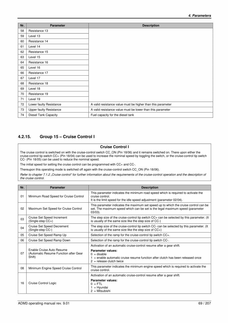
4. Parameters
ADM3 operating manual rev. 9.01 69 / 207
Nr. Parameter Description
58 Resistance 13
59 Level 13
60 Resistance 14
61 Level 14
62 Resistance 15
63 Level 15
64 Resistance 16
65 Level 16
66 Resistance 17
67 Level 17
68 Resistance 18
69 Level 18
70 Resistance 19
71 Level 19
72 Lower faulty Resistance A valid resistance value must be higher than this parameter
73 Upper faulty Resistance A valid resistance value must be lower than this parameter
74 Diesel Tank Capacity Fuel capacity for the diesel tank
4.2.15. Group 15 – Cruise Control I
Cruise Control I
The cruise control is switched on with the cruise-control switch CC_ON (Pin 18/06) and it remains switched on. There upon either the cruise-control tip switch CC+ (Pin 18/04) can be used to increase the nominal speed by toggling the switch, or the cruise-control tip switch CC- (Pin 18/05) can be used to reduce the nominal speed.
The initial speed for setting the cruise control can be programmed with CC+ and CC-.
Thereupon this operating mode is switched off again with the cruise-control switch CC_ON (Pin 18/06).
Refer to chapter 7.1.2 „Cruise control“ for further information about the requirements of the cruise-control operation and the description of the cruise control.
Nr. Parameter Description
01 Minimum Road Speed for Cruise Control This parameter indicates the minimum road speed which is required to activate the cruise control. It is the limit speed for the idle speed adjustment (parameter 02/04).
02 Maximum Set Speed for Cruise Control This parameter indicates the maximum set speed up to which the cruise control can be set. The maximum speed which can be set is the legal maximum speed (parameter 03/03).
03 Cruise Set Speed Increment (Single-step CC+)
The step size of the cruise-control tip switch CC+ can be selected by this parameter. (It is usually of the same size like the step size of CC-)
04 Cruise Set Speed Decrement (Single-step CC-)
The step size of the cruise-control tip switch CC- can be selected by this parameter. (It is usually of the same size like the step size of CC+)
05 Cruise Set Speed Ramp Up Selection of the ramp for the cruise-control tip switch CC+.
06 Cruise Set Speed Ramp Down Selection of the ramp for the cruise-control tip switch CC-.
07 Enable Cruise Auto Resume (Automatic Resume Function after Gear Shift)
Activation of an automatic cruise-control resume after a gear shift.
Parameter values: 0 = disable 1 = enable automatic cruise resume function after clutch has been released once 2 = release clutch twice
08 Minimum Engine Speed Cruise Control This parameter indicates the minimum engine speed which is required to activate the cruise control.
16 Cruise Control Logic
Activation of an automatic cruise-control resume after a gear shift.
Parameter values: 0 = FTL 1 = Hyundai 2 = Mitsubishi

4. Parameters
70 / 207 ADM3 operating manual rev. 9.01
4.2.16. Group 16 – Relay 1 / Starter Lockout
Relay 1 / Starter Lockout
� Adjustment of parameters 16/01 only in driving test and only through skilled workers with know-how in control engineering
Nr. Parameter Description
01 Output Relay 1/Starter Lockout
Parameter values: 0 = disable (the driver stage output for the relay 1 is unassigned) 1 = enable starter lockout (the output takes on the starter lockout function) 2 = enable kick down output (the accelerator pedal is in the kickdown position) 3 = enable modulat. relay Allison transm. (the driver stage output controls a modulation valve e.g. for an Allison automatic transmission) 4 = reserved 5 = split valve 2 (valve 2 for SPLIT function) 6 = starter lockout and AGS2 (Starter Lockout and AGS2 available only for automatic clutch) 7 = MIL Lamp (the power stage output controls the MI-Lamp) 8 = AdBlue Level Warning Lamp (the power stage output controls the AdBlue Level Warning Lamp) 9 = NOx Lamp as signal for the status of NOx torque limitation
02
Starter Lockout Diagnosis:
0 = enabled 1 = disabled
Starter Lockout Open Load Diagnosis.
4.2.17. Group 17 – Idle/PTO Shutdown
Idle/PTO Shutdown
� Adjustment of the parameters 17/01 to 17/09 only in driving test and through skilled workers with know-how in control engineering.
Nr. Parameter Description
01 Enable Idle Shutdown
The idle shutdown is enabled by this parameter.
Parameter values: 0 = disable 1 = enable idle shutdown with Park Brake status 2 = enable idle shutdown without Park Brake status 3 = enable idle shutdown with edge triggered accelerator pedal
02 Idle Shutdown Time This parameter determines the maximum idle time until the idle shutdown.
03 Enable PTO Shutdown
This parameter activates the idle shutdown, provided that the application has been in the PTO mode and the engine has been idling last.
Parameter values: 0 = disable 1 = enable PTO shutdown with Park Brake status 2 = enable PTO shutdown without Park Brake status 3 = enable PTO shutdown with edge triggered accelerator pedal
04 PTO Shutdown Time This parameter determines the maximum time of the PTO operation until the PTO shutdown.
05 Maximum Engine Load for PTO Shutdown This parameter determines the torque threshold, up to which a PTO shutdown is activated.
06 Time for CEL before Idle/PTO Shutdown Warning period of the Check Engine Light prior to engine shutdown.
07 Time for SEL before Idle/PTO Shutdown Warning period of Stop Engine Light prior to engine shutdown.
08 Minimum Coolant Temperature Minimum coolant temperature up to which an engine shutdown is activated.
09 Enable Idle/PTO Shutdown Override (Input MABSCH_SP)
Parameter values: 0 = disable 1 = enable, allows Engine Check switch (MABSCH_SP) to override engine idle/PTO shutdown
This parameter activates the shutdown override with the input MABSCH_SP.

4. Parameters
ADM3 operating manual rev. 9.01 71 / 207
4.2.18. Group 18 – Engine Protection Shutdown
Engine Protection Shutdown
� Adjustment of the parameters 18/01 to18/09 only in driving test and through skilled workers with know-how in control engineering.
This function is intended for non-monitored engines, e.g. for emergency power generating units or other stationary applications, e.g. with pumps, compressors or with power generating units in containers.
Refer to chapter 7.10.1 „Engine protection shutdown“ for further information on the engine protection shutdown function.
Nr. Parameter Description
01 Engine Protection Shutdown on Coolant Temperature
Engine protection shutdown on engine temperature fault indication.
Parameter values: 0 = disable 1 = enable
02 Engine Protection Shutdown on Coolant Level
Engine protection shutdown on coolant level fault indication.
Parameter values: 0 = disable 1 = enable
03 Engine Protection Shutdown on Oil Pressure
Engine protection shutdown on oil pressure fault indication.
Parameter values: 0 = disable 1 = enable
04 Engine Protection Shutdown on Oil Level
Engine protection shutdown on oil level fault indication.
Parameter values: 0 = disable 1 = enable
05 Engine Protection Shutdown Time Selection of the shutdown time for engine protection shutdown for all conditions according to parameter 18/01 to 18/04 except for the shutdown on oil pressure fault indication (18/03).
06 Engine Protection Time on Oil Pressure Selection of the shutdown time for engine protection shutdown on oil pressure fault indication.
07 Counter of Engine Protection Shutdown Overrides
Counter of engine protection shutdown overrides. The counter indicates how many times the engine shutdown was prevented by the switch „shutdown override“ (Pin 18/13).
08 Time for CEL before Engine Protection Shutdown
Warning period for check engine light. Time for the check engine light to flash prior to shutdown.
09 Time for SEL before Engine Protection Shutdown
Selection of the warning period of the engine stop light. Time for Engine Stop Light to flash prior to shutdown.
10 Overspeed BR 400
11 Overspeed BR 500
12 Overspeed BR 900
Overspeed warning (engine stop lamp red) for the engine speed 400, 500 and 900 rpm
13 Oil Level Lamp Configuration
Configuration of input signals for Oil Level Lamp. Compare chapter 7.6.6. for detailed description of the oil level indicator lamp signal
Parameter values: 0 = Oil Level 1 = Engine Overspeed 2 = Oil Level or Engine Overspeed

4. Parameters
72 / 207 ADM3 operating manual rev. 9.01
4.2.19. Group 19 – Fan
Fan
Refer to chapter 7.12.3 „Fan demand“ for further information on the fan activation function.
Nr. Parameter Description
01 Fan Type
Defines the used fan.
Parameter values: 0 = Linnig; on highway 1 = Linnig; off highway 2 = on highway Unimog /Visko 3 = NAW; Econic, Unimog 4 = Horton; Freightliner 5 = Bosch; Evobus, Unimog, off highway /1hy 6 = Bosch; Evobus, Unimog /2hy 7 = Horton; Freightliner, off highway /1 8 = BorgWarner; on highway 9 = Bosch; Unimog, Econic 251 = fan defined in MR2 255 = no fan
03 Fan Power on Engine Brake Selection of the percentage of the fan power consumption on engine brake.
05 Fan Power on air Condition Selection of the percentage of the fan power consumption on air conditioner.
07 Fan Power on PTO Selection of the percentage of the fan power consumption on PTO speed control.
08 Fan Activation on Fan Override This parameter indicates the percentage of the fan power consumption if the input „Fan“ is active, provided that the fan is demanded via digital input „LUEFTER“ (Pin 18/15).
09 Coolant Temperature at 0% Fan Selection of the coolant temperature if the fan is OFF (0% fan power consumption)
10 Coolant Temperature at 100% Fan Selection of the coolant temperature if the fan is ON (100% fan power consumption).
11 Hold time Fan
Maximum value generation based on the parameters 19/01 to19/03, 19/06 and 19/07, which is considered to be the resulting fan demand. A time-delayed reduction of the fan power consumption takes place, if the resulting value falls. This prevents fast power jumps of the fan in the case of a frequent fan demand.
12 Ramp Fan A new value (percentage of fan power consumption) will be achieved over a ramp. The ramp has the same gradient, regarding to increasing and decreasing values.
13 Fan Power on DSF0 Selection of the percentage of fan power consumption for a conventional retarder, input DSF0 at pin 12/10 is used for information about retarder intervention, compare chapter 7.12.2. (Conventional Retarder)
14 Fan Power on DSF1 Selection of the percentage of fan power consumption for a conventional retarder at input DSF1 (pin 12/09), compare chapter 7.12.2. (Conventional Retarder)
4.2.20. Group 20 – Remote Accelerator Pedal
Remote accelerator pedal
This group contains parameters which define the remote accelerator pedal evaluation.
Refer to chapter 7.3 „Accelerator pedal/Remote accelerator pedal“ for further information on the remote accelerator pedal function.
Risk of accident!
Changes to the parameters in this group must only be performed by specially trained personnel or after consultation with the engine manufacturer. Changes to the parameters of this group must only be performed by specially trained personnel or after consultation with the engine manufacturer. It is not normally necessary to change these parameters.
4. Parameters
ADM3 operating manual rev. 9.01 73 / 207
Nr. Parameter Description
01 Enable Remote Accelerator Pedal Input
This parameter indicates, if a remote accelerator pedal is available or not. The evaluation and the monitoring of the HFG signals must be deactivated in the case of a system without remote accelerator pedal. In this case the parameter value 0 has to be set.
Parameter values: 0 = disable 1 = enable
02 Delay Time for Remote Accelerator Pedal Calibration
03 Maximum Change of Remote Accelerator Pedal Wide Open
04 Remote Accelerator Pedal Signal Filter
�
Adjustment of the parameters 20/02 to 20/06 only in driving test and only through skilled workers with know-how in control engineering.
05 Remote Accelerator Pedal Idle Position Definition of the upper limit of the remote accelerator pedal position for the status „idle“. In this case the reference point (0%) is the minimum stop limit of the remote accelerator pedal.
06 Remote Accelerator Pedal Wide Open Position
Definition of the lower limit of the remote accelerator pedal position for the status „Wide open“. In this case the reference point (0%) is the minimum stop limit of the remote accelerator pedal. The upper stop limit of the remote accelerator pedal is automatically adjusted!
07 HFG Diagnostics Only With Active Pin “FG-Wahl”
Diagnostics of the Remote Accelerator Pedal (SPN 974, FMI 2, 3 or 4) can be chosen to be performed always or only in combination with an active pin 18/7
Parameter values: 0 = always 1 = only by active pin 18/7 throttle select
4.2.21. Group 21 – Droop Control Mode
Driving with PTO speed (ADR)
In this operating mode it is constantly switched over to PTO speed control operation (ADR).
The effective limit values from PLD/MR2 internal limit values, limit values of the parameter group 03 (general limits) and limit values of the parameter group 05 and 06 (variable limits) remain active.
Refer to chapter 7.2.1.3 „Configuration of the operating mode driving with PTO speed control in special applications“ for further information on the function „driving with PTO speed“.
Nr. Parameter Description
01 Droop Control Mode
Activation of the operating mode „driving with PTO speed control“
Parameter values: 0 = function disabled. 1 = without pedal tolerance 2= with pedal tolerance
02 Droop Control Governor Type Selection of the governor type for the operating mode „driving with PTO speed control
03 Droop Maximum Engine Torque Maximum engine torque for the operating mode „driving with PTO speed control“
4.2.22. Group 22 – TSC1 Limiter Governor (N max)
TSC1 Limiter Governor (n max)
Nr. Parameter Description
01 Governor TSC1 Transmission Governor for torque speed control transmission limitation.
02 Governor TSC1 ABS Governor torque speed control ABS limitation.
03 Governor TSC1 Jack Knife Governor torque speed control Jack Knife limitation.
04 Governor TSC1 ACC Governor torque speed control ACC limitation.
20 Speed Gov# TSC1 condition #0 MR speed governor# which is used for TSC1 requested speed control condition #0. See J1939/71 SPN 696
4. Parameters
74 / 207 ADM3 operating manual rev. 9.01
Nr. Parameter Description
21 Speed Gov# TSC1 condition #1 MR speed governor# which is used for TSC1 requested speed control condition #1. See J1939/71 SPN 696
22 Speed Gov# TSC1 condition #2 MR speed governor# which is used for TSC1 requested speed control condition #2. See J1939/71 SPN 696
23 Speed Gov# TSC1 condition #3 MR speed governor# which is used for TSC1 requested speed control condition #3. See J1939/71 SPN 696
4.2.23. Group 23 – Limiters II
Limiters II
Nr. Parameter Description
01 Torque Factor Gear Down Protection Torque reduction factor in gears below the ratio that is set in parameter 23/02.
02 Gear Ratio for Gear Down Protection Torque reduction occurs to gear ratios below this value. Review also parameter 23/01.
03 Torque Factor High Gear Power Torque reduction factor in gears below the ratio that is set in parameter 23/04.
04 Gear Ratio for High Gear Power Torque reduction occurs to gear ratios below this value. Review also parameter 23/03.
06 Maximum Engine Speed for Progressive Shifting
Engine RPM is limited to this value when vehicle is in a gear ratio below the value set in 23/19. Review also parameter 23/07.
07 Gear Ratio for Progressive Shifting Gear Ratio at which 23/18 is effected. Review also Parameter 23/06.
08 Acceleration Limiter Engine Speed Threshold
Upper-Speed limit:= actual engine speed + engine-speed-threshold.
09 Acceleration Limiter Minimum Engine Speed Threshold
Limitation enabled if an actual engine speed is higher than Minimum Engine Speed threshold.
10 Acceleration Limiter Ramp up Rate Acceleration limiter engine speed ramp.
11 Acceleration Minimum Engine Torque Minimum value of torque reduction in percent of maximum torque. To enable the function the parameter must be less than 100%.
12 Acceleration Droop Parameter Droop governor parameter.
13 Gear protection 1st speed When V < V1 then the engine torque limit exist.
14 Gear protection 2nd speed When V > V2 then there is no limitation.
15 Gear protection, Torque Limitation When V < V1 then torque limitation exist.
4.2.24. Group 24 – Vehicle Parameters II
Vehicle Parameters II
This group contains only not visible parameters.
4.2.25. Group 25 – XTempomat
XTempomat
This group contains only not visible parameters.
4.2.26. Group 26 – VIN Vehicle Identification Number
VIN Vehicle Identification Number

4. Parameters
ADM3 operating manual rev. 9.01 75 / 207
Nr. Parameter Description
06 VIN
4.2.27. Group 27 – Fleetmanagement
Fleet Management
Nr. Parameter Description
01 Enable Fleet Management Enable function of the fleet management
02 Enable Hard Brake Incident Enable function of hard brake incident
03 Enable Service Interval Data Enable function of service interval data
04 Enable Monthly Trip Data Enable function of monthly trip data
05 Enable Detailed Alert System Enable function of detailed alert system
06 Enable Engine Usage Data Enable function of usage data
07 Fuel Density The relationship between fuel mass and volume.
17 ECU ID for Fleetmanagement Parameter values: 0 = send ADM identification. 1 = send DDEC identification.
4.2.28. Group 28 – Real Time Clock
Real Time Clock
This group contains only not visible parameters.
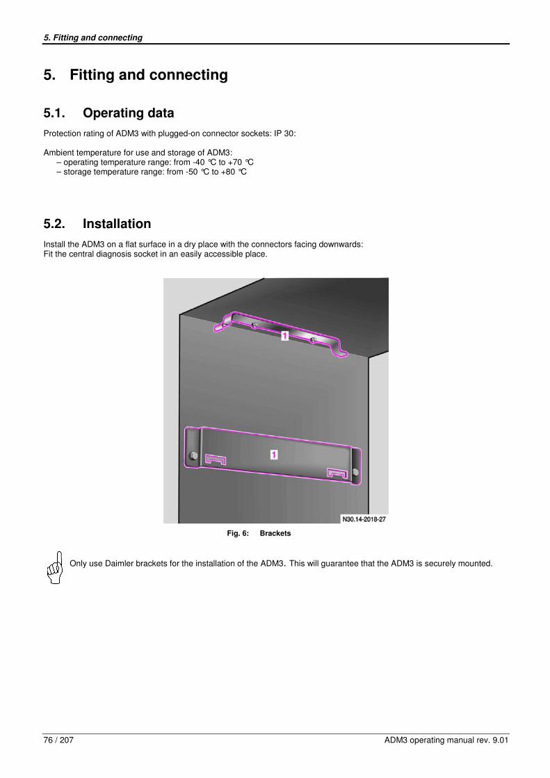
5. Fitting and connecting
76 / 207 ADM3 operating manual rev. 9.01
5. Fitting and connecting
5.1. Operating data
Protection rating of ADM3 with plugged-on connector sockets: IP 30: Ambient temperature for use and storage of ADM3:
– operating temperature range: from -40 °C to +70 °C – storage temperature range: from -50 °C to +80 °C
5.2. Installation
Install the ADM3 on a flat surface in a dry place with the connectors facing downwards: Fit the central diagnosis socket in an easily accessible place.
Fig. 6: Brackets
Only use Daimler brackets for the installation of the ADM3. This will guarantee that the ADM3 is securely mounted.
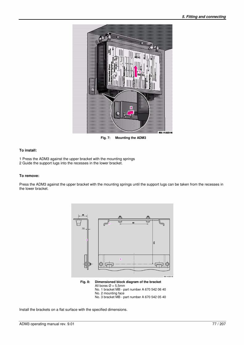
5. Fitting and connecting
ADM3 operating manual rev. 9.01 77 / 207
Fig. 7: Mounting the ADM3
To install: 1 Press the ADM3 against the upper bracket with the mounting springs 2 Guide the support lugs into the recesses in the lower bracket. To remove: Press the ADM3 against the upper bracket with the mounting springs until the support lugs can be taken from the recesses in the lower bracket.
Fig. 8: Dimensioned block diagram of the bracket All bores Ø = 5,5mm No. 1 bracket MB - part number A 670 542 06 40 No. 2 mounting face No. 3 bracket MB - part number A 670 542 05 40
Install the brackets on a flat surface with the specified dimensions.
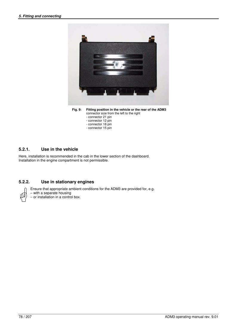
5. Fitting and connecting
78 / 207 ADM3 operating manual rev. 9.01
Fig. 9: Fitting position in the vehicle or the rear of the ADM3 connector size from the left to the right - connector 21 pin - connector 12 pin - connector 18 pin - connector 15 pin
5.2.1. Use in the vehicle
Here, installation is recommended in the cab in the lower section of the dashboard. Installation in the engine compartment is not permissible.
5.2.2. Use in stationary engines
Ensure that appropriate ambient conditions for the ADM3 are provided for, e.g. – with a separate housing – or installation in a control box.

5. Fitting and connecting
ADM3 operating manual rev. 9.01 79 / 207
5.3. Connecting up
Risk of accident!
„Terminal 15“ and „Terminal 50“ of the control units are high-resistance signal inputs which draw current in the order of mA. Impermissible residual voltage at these inputs could affect LOW level detection. Consequence:
– engine starts unexpectedly (terminal 50) – the engine can no longer be switched off (terminal 15)
If the engine starts unexpectedly and the drive train is closed (transmission not in neutral), the vehicle could unexpectedly start moving or set the working machine in operation, constituting a risk to life and limb.
A battery isolator switch is only to be fitted to one battery terminal (positive)Wiring a ground connection is not permissible and could result in damage to the control units PLD/MR2 and ADM3-FR.
Observe the following guidelines when connecting up the ADM3:
– Only use Daimler star quad cables to wire up CAN connections. These cables are specially designed for vehicle CAN application (EMC).
– The CAN connection between the PLD/MR2 and ADM3 must not exceed a length of 15 meters.
– Switching off the power supply (terminal 30) is only permissible at the end of the control unit’s run-on phase. The run-on phase begins when terminal 15 is switched off and lasts for about 5 seconds. If necessary, new fault codes are wrote into the memory during the run-on phase and stored in the control unit ADM3, in order to preserve these new values when the ADM3 is switched off.
– To avoid fault entries, the input „terminal 15“ should be switched simultaneously for all control units.
– To avoid fault entries, the input „terminal 50“ (engine start) should be switched simultaneously for the ADM3 and PLD/MR2 control units.
– If a battery charge warning lamp is wired, it is important that a blocking diode is installed, as it would not otherwise be possible to switch the engine off via terminal 15.
– The ground connection of all electrical consumers should be distributed in a star formation from the central ground point. If the ground connection is not arranged in a star formation, or if the current flows through frame members with poor conductivity, malfunctions may develop due to ground offset or EMC effects.

6. Parameter programming with the diagnosis unit minidiag2
80 / 207 ADM3 operating manual rev. 9.01
6. Parameter programming with the diagnosis unit minidiag2
The following functions can be performed with the diagnosis unit minidiag2:
− Read out the control unit version
− Read out/clear the fault memory
− Read out actual value data (e.g. parameter status, analog values, binary values of inputs and outputs)
− Teach in accelerator pedal (as routine of ADM3)
− Reset all parameter values to their default values (as routine of ADM3)
− Parameter programming of ADM3
The implementation of the functions mentioned above is described in the operating manual of the minidiag2.
7. Application
ADM3 operating manual rev. 9.01 81 / 207
7. Application
The following pages describe the areas of application of the ADM3 and the associated inputs/input data, outputs/output data and parameters.
7.1. Driving mode and PTO speed control
The vehicle control adaption module (ADM3) differentiates between the driving mode and the PTO speed control (ADR operation).
In the operating state „driving mode“ the ADM3 preselects the status „torque demand“ from the PLD/MR2 engine management. ADM3 determines a nominal engine torque and transmits simultaneously a minimum engine speed and a maximum engine speed to the PLD/MR2 engine management. In the operating state „PTO speed control“, the ADM3 preselects the status „speed control“ from the PLD/MR2 engine management. The ADM3 determines a nominal speed and transmits simultaneously a governor type and a maximum torque to the PLD/MR2 engine management. The limits preset in the PLD/MR2 engine management can not be exceeded. This guarantees that limit values of the engine, which are relevant for the function and the certification, can not be exceeded. The operating range of the engine can, in addition, be restricted by adjustments of the ADM3. The engine torque, the engine speed and the road speed can be limited through configuration. The possibilities provided for this, are summarized in the chapter 7.9. After starting the engine, refer to chapter 7.4, the engine switches to the preset operating mode.
7.1.1. Driving mode
In the default setting the ADM3 is in the driving mode. The input variables for the driving mode are:
- the accelerator pedal - the remote accelerator pedal or - a torque demand via SAE J 1939
In the ADM3 default setting a nominal value demand is provided on the basis of the evaluation of an accelerator pedal. ADM3 enables the application of an analog accelerator pedal as well as the application of a PWM accelerator pedals. Both have to be adjusted on the initial start-up. Refer to chapter 10, Routine No. 1. An additional remote accelerator pedal can be enabled by configuration, refer to chapter 4.2. The demand of an engine torque is, in addition, possible via SAE J 1939 TSC1 Byte 4 The output/setting value in the driving mode is the engine torque. Simultaneously a minimum and a maximum speed are transmitted to the PLD/MR2. The ADM3 calculates a nominal torque value for the PLD/MR2 engine management on the basis of the accelerator pedal position, the remote accelerator pedal or a SAE J1939 demand, and transmits it to the PLD/MR2 via the CAN data bus. The adjustment range of the nominal torque value ranges between the currently active minimum- and maximum torque. The limit values are defined by the parameters of group 03 „Common Limiters“ or group 05 „Limiters LIM0 and LIM1“ No.0 and No.1 or group 06 „Limiters AC / LIM2“ No.2. The PLD/MR2-internal limit values are also effective.
7.1.1.1. Idle speed adjustment
The PLD/MR2 engine management is delivered with a preset idle speed. If an increased idle speed is required in the driving mode, this can be realized by an adjustment of the engine speed via the cruise-control tip switches CC+ and CC-. However the adjusted idle speed will not be present after a restart.
7. Application
82 / 207 ADM3 operating manual rev. 9.01
Cruise-control switch (Pin 18/06) in the off-position: The idle speed can be adjusted via the cruise-control tip switch CC+ (Pin 18/05) or CC- (Pin 18/04). It can be increased with CC+ and decreased with CC-. Further modifications of the function „idle speed adjustment“ can be realized with the parameter group 03: Parameter group 3:
Nr. Parameter Description
8 Desired Idle Speed Single Step Increase/Decrease
Idle-speed can be adjusted with the cruise-control tip switch CC+ (Pin 18/05) or CC- (Pin 18/04) and with the cruise-control switch (Pin18/06) is in the off position. This parameter determines the step size, which applies to both cruisecontrol tip switches and is of the same size when increasing with CC+ and decreasing with CC-
9 Desired Idle Speed Ramp Rate Increase/Decrease
This parameter indicates the ramp, with which the idle-speed is adjusted when the tip switches are activated continuously.
10 Maximum Adjusted Idle Speed Upper final value of idle speed adjustment.
11 Max. Road Speed for Idle Increase/Decrease
Limit speed of the vehicle, up to which the idle-speed adjustment is enabled.
7.1.1.2. Vehicle speed limiting
The vehicle control adaption module (ADM3) is certified as per directive 92/24/EWG as a speed limiter for keeping to legally specified maximum speeds. The legally specified maximum speed is set in parameter 03/03. This parameter value is set to 85km/h and can only be changed with the relevant authorization. The set value is always valid and can only be superseded by lower vehicle speeds using the programmable limitations. If the vehicle exceeds the maximum speed (i.e. driving downhill), the vehicle can be slowed down by using the service brake or engine brake. The engine brake can only be activated by switching Input MBR_L or MBR_H to ground. For further information about „Engine Brake“ refer to chapter 7.5 The engine brake will not be activated automatically because the Speed limitation with Engine Brake is deactivated (value parameter 10/05 is set to 0 km/h). Refer to chapter 7.1.1.3 Parameters:
- 03/03 Maximum road speed (legal) parameter value = 85 km/h
- 10/05 Enable Engine Brake on Road Speed Limiter parameter value = 0 km/h
7.1.1.3. Vehicle speed limiting with engine brake
The vehicle control adaption module (ADM3) is certified as per directive 92/24/EWG as a speed limiter for keeping to legally specified maximum speeds. The legally specified maximum speeds is set in parameter 03/03. This parameter value is set to 85km/h and can only be changed with the relevant authorization. The set value is always valid and can only be superseded by lower vehicle speeds using the programmable limitations. If the vehicle exceeds the maximum speed (i.e. driving downhill) and the Speed limitation with engine brake is activated (value parameter 10/05 is bigger than 0 km/h), the Engine brake will be activated automatically, if vehicle speed exceeds the summation of legally specified maximum speeds and set speed threshold. The speed threshold is set in parameter 10/05. Speed limitation with engine brake activates always all configured engine brakes. For further information about „Engine Brake“ refer to chapter 7.5 Parameters:
- 03/03 Maximum road speed (legal) parameter value = 85 km/h
- 10/05 Enable Engine Brake on Road Speed Limiter parameter value > 0 km/h

7. Application
ADM3 operating manual rev. 9.01 83 / 207
7.1.2. Cruise control operation
In the driving mode a cruise control operation can be activated via switches and tip switches in the instrument panel. Thereby the engine is torque controlled, in order to maintain the preset vehicle speed. This ensures that a maximum vehicle speed is not exceeded, refer to chapter 7.1.1.2 for „Vehicle speed limiting“. The cruise control function is enabled via the switch „CC On“. The speed control is activated via the switch CC+ or CC-, provided that the current vehicle speed exceeds a minimum value. See parameter below. The speed control is activated and the nominal value is set to the actual speed value via the switch CC- (set/decelerate). When the cruise control is active, the nominal speed can be reduced gradually by momentarily toggling the switch CC-. Holding the switch CC- will reduce the step size via a ramp. The step size and the time constant of the ramp can be configured by a parameter (see below). The cruise control is deactivated if the brake or clutch pedal is actuated. For reasons of safety the cruise control is also deactivated, if the ADM3 detects an excessive deceleration of the vehicle. If the cruise control has been deactivated, toggling the switch CC+ (Resume/Acceleration) will reactivate the cruise control set point which was active before the deactivation. If the cruise control is active, momentarily toggling the switch CC+ will gradually increase the nominal speed. Holding the switch CC+ will increase the nominal speed value via a ramp. The step size and the time constant of the ramp can be configured by parameters (see below). The function „auto resume“ can be configured with the parameter 15/07. If the auto resume is enabled, the cruise control will not be deactivated, when the clutch pedal is actuated, but it switches over to a stand by mode. The current nominal speed is saved for a period of ....sec and is automatically resumed upon releasing the clutch. It is communicated to the PLD/MR2, if during the cruise control operation the accelerator pedal or the remote pedal (if activated) or the SAE J1939 demand a torque which is higher than the torque currently demanded by the cruise control. As a result, the road speed is accelerated with the current nominal speed, until the torque demanded by the cruise control becomes the determining torque again. Upon switching off the cruise control function via CC On, the nominal speed of the cruise control is set to the minimum speed (parameter 15/01). Parameter group 15:
Nr. Parameter Description
01 Minimum Road Speed for Cruise Control This parameter indicates the minimum road speed which is required to activate the cruise control. It is the limit speed for the idle speed adjustment (parameter 02/04).
02 Maximum Set Speed for Cruise Control This parameter indicates the maximum set speed up to which the cruise control can be set. The maximum speed which can be set is the legal maximum speed (parameter 03/03).
03 Cruise Set Speed Increment (Single-step CC+)
The step size of the cruise-control tip switch CC+ can be selected by this parameter. (It is usually of the same size like the step size of CC-)
04 Cruise Set Speed Decrement (Single-step CC-)
The step size of the cruise-control tip switch CC- can be selected by this parameter. (It is usually of the same size like the step size of CC+)
05 Cruise Set Speed Ramp Up Selection of the ramp for the cruise-control tip switch CC+.
06 Cruise Set Speed Ramp Down Selection of the ramp for the cruise-control tip switch CC-.
07 Enable Cruise Auto Resume (Automatic Resume Function after Gear Shift)
Activation of an automatic cruise-control resume after a gear shift.
08 Minimum Engine Speed Cruise Control This parameter indicates the minimum engine speed which is required to activate the cruise control.
16 Cruise Control Logic Activation of an automatic cruise-control resume after a gear shift.
7.1.2.1. Cruise control with engine brake
In the cruise control operating mode the ADM3 authorizes an additional activation of the engine brake, if the set speed is exceeded during downhill driving. Parameter group 10 (Engine Brake) determines how the engine brake supports the cruise control. The parameter 10/06 (value=1) determines that the engine brake is automatically activated if the vehicle exceeds a preset value.

7. Application
84 / 207 ADM3 operating manual rev. 9.01
The parameters 10/07 to 10/12 are the cut-in and cut-off speeds (threshold values) for the engine brake step 1 (MBR_L), engine brake step 2 (MBR_H) and step 3 (turbo brake). In this case the parameter values are the differential speeds referred to the set speed of the cruise control. The differential speed in parameter 10/07 has to be exceeded, so that the constantly open throttle is activated during the cruise control mode. The constantly open throttle is switched off again, if the speed falls below the differential speed in parameter 10/08. The differential speed in parameter 10/09 has to be exceeded, so that the engine retarder flap is activated during the cruise control mode. The engine brake is switched off again, if the speed falls below the differential speed in parameter 10/10. The differential speed in parameter 10/11 has to be exceeded, so that the turbo brake is activated during the cruise control mode. The turbo brake is switched off again, if the speed falls below the differential speed in parameter 10/12. Value changes of the parameters 10/07, 10/08, 10/09 , 10/10, 10/11, 10/12 of the engine brake must only be performed by specially trained personnel or after consultation with the engine manufacturer. It is normally not necessary to change these parameters.
7.1.2.2. Cruise control when using a stalk switch
It is possible to combine the ADM3 with a stalk switch (Part.Nr. A 008 545 10 24 5B21) for cruise control and engine brake operation. For connecting the stalk switch, Pins 18/04 and 18/05 are used conventionally for Cruise Control Set+Coast and Cruise Control Resume+Accelerate respectively. Pin 18/06, marked as CC_EIN is used as a Cruise Control Pause Switch, compare the following figures too. For safety reasons each cruise control operation leads to an inverted signal on the Quit output of the stalk switch which is connected to Pin 12/07 (DSF2). Parameter 13/37 (Input DSF2) has to be set to 3 (Quit Signal for CC with Stalk Switch) for activating of the stalk switch functionality. In addition the described stalk switch offers a button for activating the Temposet functionality. The appropriate pin 12/09 (DSF0) or 12/10 (DSF1) has to be connected to the Temposet pin of the stalk switch, the corresponding setting of parameter 13/17 or 13/18 respectively enables Temposet.
Fig. 10: Stalk switch functions
Fig. 11: Stalk switch wiring
Nr. Function
1 CC+, increase speed, resume 2 CC-, decrease speed, set 3 Engine Brake, one step 4 CC Pause 5 Temposet
7. Application
ADM3 operating manual rev. 9.01 85 / 207
It shall be pointed out that the stalk switch functions are activated only by changing the value of parameter 13/37 to 3. Because Pin 12/07 (DSF2) is used as Quit signal for the stalk switch, increased idle speed by simply activating CC+ and CC- is not possible any more. The driver may use the PTO speed control (ADR) to achieve similar functionality.
In the case the input pattern deriving from the inputs CC+, CC-, CC Pause und Quit do not satisfy one of the possible 4 patterns, plausibility check errors for the CC+ and CC- and CC Pause switches are set depending on the inputs, compare chapter 9. Then no cruise control operation is possible. The stalk switch offers also the possibility for engine brake operation with two stages MBR Low and MBR High, but no Limiter function. Please refer to chapter 7.5.6. for details. Inputs: - Pin 12/07 DSF2 - Pin 12/09 DSF0 or 12/10 DSF1 - Pin 18/04 CC- - Pin 18/05 CC+ - Pin 18/06 CC_EIN (used as CC Pause) - Pin 18/09 MBR_H - Pin 21/03 Kl.31 Parameters:
- 13/12 Configuration CC set/coast and resume/accel parameter value = 0 (hardwired)
- 13/13 Configuration CC Pause parameter value = 0 (disabled or stalk switch)
- 13/17 Configuration Variable Input DSF0 parameter value = 3 (enable temposet)
- 13/18 Configuration Variable Input DSF1 parameter value = 3 (enable temposet)
- 13/37 Input DSF2 parameter value = 3 (Quit Signal for CC with Stalk Switch)
7.1.2.3. Temposet function
ADM3 provides the possibility to limit the vehicle speed to the current speed (temposet function), via a switch in the instrument panel. A temposet function can be assigned to the digital inputs DSF0 or DSF1 by configuration. Caution: DSF0 and DSF1 are multiply assigned functions, only one function each can be selected! Speed limiting to the current value of the driving speed is activated by toggling the selected DSF-switch (temposet function). The temposet function is deactivated by toggling the selected DSF-switch once again. Depressing the accelerator pedal into the kick-down position deactivates an active temposet function, and the vehicle can be accelerated, exceeding the set temposet-limit-speed. Inputs (alternatives) – Pin 12/10 digital special function 0 (DSF0), input switched to battery voltage – Pin 12/09 digital special function 1 (DSF1), input switched to ground Parameter (alternatives)
–13/17 Configuration Variable Input DSF0: Parameter value 3 = Enable Temposet
–13/18 Configuration Variable Input DSF1: Parameter value 3 = Enable Temposet
The inputs DSF0 or DSF1 have to be connected according to the configuration of the temposet concerning DSF0 and DSF1: Please note, that the digital input DSF0 has to be switched to battery voltage and the digital input DSF1 has to be switched to ground.

7. Application
86 / 207 ADM3 operating manual rev. 9.01
7.2. PTO speed control (ADR)
The vehicle control adaption module (ADM3) differentiates between driving mode and PTO speed control (ADR operation). The PTO speed control is applied: e.g. with cranes, piste maintenance equipment, harvesters, sweeping machines, garbage trucks, compressors, power generating aggregates, pumps etc. The output/setting value of ADM3 in the PTO mode is the engine speed. Simultaneously a governor type and a maximum engine torque is transmitted to the PLD/MR2. The nominal speed value is determined by the ADM3 on the basis of the input values listed below, and transmitted to the PDL/MR2 engine control via the CAN data bus. The adjustment range of the nominal speed value and the engine torque limit value ranges between the currently active minimum- and maximum values. These limits are (like in the driving mode) defined by the parameters of group 03 „Common Limters“ or group 05 „Limiters LIM0 and LIM1“ No.0 and No.1 or group 06 „Limiters AC/LIM2“ No.2.
7.2.1. The three operating modes of the PTO speed control
- Driver’s cab PTO (control from the driver’s cab via CC+ and CC-) - PTO with fixed speeds via the PTO switch - Driving with PTO with special applications
7.2.1.1. Driver’s cab PTO
The function „Configuration PTO speed control“ is enabled with the parameter 07/01 :
Nr. Parameter Description
01 Configuration PTO Speed Control
Parameter values: 0 = disabled (PTO speed control is disabled) 1 = enabled (PTO speed control is enabled) 2 = enabled if neutral (PTO speed control is only enabled as long as the transmission is in neutral position) 3 = enabled if neutral and park brake (PTO speed control is only enabled as long as the transmission is in neutral position and the parking brake is closed) 4 = enabled if park brake (PTO speed control is only enabled as long as the parking brake is closed)
When the vehicle is stationary, a PTO mode is enabled by switching on the cruise control switch (Pin 18/06). ADM3 is switched over to PTO mode via the cruise-control tip switches CC+ (Pin 18/05) or CC- (Pin 18/04). The nominal value for the PTO speed can be adjusted, starting with the idle speed. It can be increased with CC+ and decreased with CC-. The starting speed, when initially toggling the switches CC+ or CC-, can be preset with the parameters 07/09 and parameter 07/12. The current PTO speed can be overridden via the accelerator pedal and the remote accelerator pedal, provided that they are enabled for the PTO mode with the parameters 07/04. Further modifications of the function „PTO Control on PTO and CC pin“ can be realized with the parameters 07/02 to 07/15.

7. Application
ADM3 operating manual rev. 9.01 87 / 207
Parameter group 07:
Nr. Parameter Description
01 Configuration PTO Speed Control
Parameter values: 0 = disabled (PTO speed control is disabled) 1 = enabled (PTO speed control is enabled) 2 = enabled if neutral (PTO speed control is only enabled as long as the transmission is in neutral position) 3 = enabled if neutral and park brake (PTO speed control is only enabled as long as the transmission is in neutral position and the parking brake is closed) 4 = enabled if park brake (PTO speed control is only enabled as long as the parking brake is closed)
02 Maximum PTO Speed with CC+ Switch Maximum speed, which can be achieved for the PTO speed control when the nominal speed is increased via the cruise control tip switch CC+
03 Minimum PTO Speed with CC- Switch Minimum speed, which can be achieved for the PTO mode when the nominal speed is decreased via the cruise control tip switch CC
04 PTO Throttle Override Enable
This parameter indicates, if the engine speed in the PTO mode can be enabled to be increased with the throttle input
Parameter values: 0 = Disable 1 = Enable engine speed in PTO mode to be increased with throttle input
05 Max. Engine Speed for Throttle Override This parameter indicates the maximum speed when the accelerator pedal is actuated in PTO-mode.
06 PTO dropout on Service break or park brake enabled
This parameter indicates if the PTO is caused to drop out when the service brake or the park brake is actuated.
Parameter values: 0 = No PTO drop out with Service brake or park brake enabled 1 = Causes PTO to drop out if the Service brake or the park brake is being depressed 2 = Drop out on S brake 3 = Drop out on park brake
07 PTO dropout on clutch enabled
This parameter defines, if the PTO is caused to drop out when the clutch is being depressed.
Parameter values: 0 = No PTO drop out with clutch pedal 1 = Causes PTO to drop out if the clutch is being depressed
08 Maximum Road Speed in PTO Mode Maximum road speed, up to which a PTO mode is possible
09 PTO Set Speed with CC- Switch Starting speed, if PTO mode has been activated via CC-
10 PTO Speed Governor Type with CC- Switch
Governor type selection, if PTO mode has been activated via CC-
11 Maximum PTO Torque with CC- Switch Maximum torque, if PTO mode has been activated via CC-
12 PTO Set Speed with CC+ Switch Starting speed, if PTO mode has been activated via CC+
13 PTO Speed Governor Type with CC+ Switch
Governor type selection, if PTO mode has been activated via CC+
14 Maximum PTO Torque with CC+ Switch Maximum torque, if PTO mode has been activated via CC-+
15 PTO Ramp Rate In PTO mode, a new engine speed will be achieved over a ramp
7.2.1.2. PTO with fixed speed via the PTO switch
The conditions for enabling and disabling the function „PTO with fixed speeds via PTO switch“ correspond to the conditions for enabling and disabling the function „driver’s cab PTO“. The function „PTO with fixed speeds“ is enabled with the parameter 07/01:
Nr. Parameter Description
01 Configuration PTO Speed Control
Parameter values: 0 = disabled (PTO speed control is disabled) 1 = enabled (PTO speed control is enabled) 2 = enabled if neutral (PTO speed control is only enabled as long as the transmission is in neutral position) 3 = enabled if neutral and park brake (PTO speed control is only enabled as long as the transmission is in neutral position and the parking brake is closed) 4 = enabled if park brake (PTO speed control is only enabled as long as the parking brake is closed)

7. Application
88 / 207 ADM3 operating manual rev. 9.01
Additional conditions for disabling and enabling this function can be activated with the parameters 07/04 to 07/08: Parameter group 07:
Nr. Parameter Description
04 PTO Throttle Override Enable
This parameter indicates, if the engine speed in the PTO mode can be enabled to be increased with the throttle input
Parameter values: 0 = Disable 1 = Enable engine speed in PTO mode to be increased with throttle input
05 Max. Engine Speed for Throttle Override This parameter indicates the maximum speed when the accelerator pedal is actuated in PTO-mode.
06 PTO dropout on Service break or park brake enabled
This parameter indicates if the PTO is caused to drop out when the service brake or the park brake is actuated.
Parameter values: 0 = No PTO drop out with Service brake or park brake enabled 1 = Causes PTO to drop out if the Service brake or the park brake is being depressed 2 = Drop out on S brake 3 = Drop out on park brake
07 PTO dropout on clutch enabled
This parameter defines, if the PTO is caused to drop out when the clutch is being depressed.
Parameter values: 0 = No PTO drop out with clutch pedal 1 = Causes PTO to drop out if the clutch is being depressed
08 Maximum Road Speed in PTO Mode Maximum road speed, up to which a PTO mode is possible
Up to three preset fixed speeds can be activated via the PTO switch (Pin 18/10). Upon initial switch-on a PTO speed control is activated with the fixed speed 1. If it is switched on and off again (less than 1 second), the nominal engine speed is set to the next nominal speed, fixed speed 2. The fixed speed 3 can be selected in the same way and thereupon it can be switched to the fixed speed 1. The current PTO speed can be overridden with the accelerator pedal or the remote accelerator pedal, provided that they have been enabled for the PTO mode in the parameter 07/04. The PTO speed control is switched off, as soon as the PTO switch is in the OFF position for more than one second. The operating mode PTO via the PTO switch has priority over the driver’s cab PTO via the CC tip switches. Further modifications of the function „PTO with fixed speeds via the PTO switch“ can be realized with the parameters 07/16 to 07/25: Parameter group 07:
Nr. Parameter Description
16 Number of Speeds via Remote PTO (Pin 18/10)
Number of fixed speeds when activating the PTO speed control via the PTO switch:
Parameter values: 1 = one fixed speed can be selected Parameters 07/17 to 07/19 are effective 2 = two fixed speeds can be selected Parameters 07/17 to 07/22 are effective 3 = three fixed speed can be selected Parameters 07/17 to 07/25 are effective
(the generally valid and variable limits and the limits of the PLD/MR2 remain effective)
17 PTO Speed #1 Programmable speed value for fixed speed #1
18 PTO Speed #1 Governor Type Governor type selection, if fixed speed #1 has been activated
19 PTO Speed #1 Maximum Engine Torque Maximum engine torque, if fixed speed #1 has been activated
20 PTO Speed #2 Programmable speed value for fixed speed #2
21 PTO Speed #2 Governor Type Governor type selection, if fixed speed #2 has been activated
22 PTO Speed #2 Maximum Engine Torque Maximum engine torque, if fixed speed #2 has been activated
23 PTO Speed #3 Programmable speed value for fixed speed #3
24 PTO Speed #3 Governor Type Governor selection, if fixed speed #3 has been activated
25 PTO Speed #3 Maximum Engine Torque Maximum engine torque, if fixed speed #3 has been activated

7. Application
ADM3 operating manual rev. 9.01 89 / 207
7.2.1.3. Driving with PTO with special applications
This operating mode has to be selected, if the application has to remain permanently in the PTO mode. A permanent operating mode „PTO speed control“ can be set for ADM3 with the parameter 21/01. The function idle speed adjustment via CC+ and CC- remains active in this operating mode. Parameter group 21.
Nr. Parameter Description
01 Droop Control Mode
Activation of the operating mode „driving with PTO speed control“
Parameter values: 0 = function disabled. 1 = without pedal tolerance 2 = with pedal tolerance
02 Droop Control Governor Type Selection of the governor type for the operating mode „driving with PTO speed control
03 Droop Maximum Engine Torque Maximum engine torque for the operating mode „driving with PTO speed control“
7.2.2. Governor types for the PTO speed control
In the PLD/MR2 different governor types can be selected via CAN for the operating mode speed control. In ADM3 the corresponding governor types can be assigned to the respective operating modes by means of a configuration. Driver’s cab PTO via CC switches: The governor type selection is carried out with the parameter 7/10 (for the activation of the PTO via CC-) or with the parameter 07/13 (for the activation of the PTO via CC+). PTO with fixed speeds via the PTO switch: The governor type selection is realized with the parameter 07/18 (for the fixed speed #1) or with the parameter 07/21 (for the fixed speed #2) or with the parameter 07/24 (for the fixed speed #3). Driving with PTO with special applications: The governor type selection is realized with the parameter 21/02.
7.2.2.1. Features of the governor types
Governor Type Number
Feature Application
01 Dynamic PID governor, with particular consideration of the large and the small signal range
PTO speed control Standard PTO governor
02 Highly dynamic governor related to characteristic curves
Aggregates with highly dynamic load characteristics e.g. concrete pump
03 corresponds to governor type 1, but increased dynamic due to high droop parameter
PTO speed control
04 corresponds to governor type 1, but reduced dynamic due to low droop parameter
PTO speed control
05 corresponds to governor type 1, but low dynamic due to very low droop parameter
PTO speed control
06 .. 11 Reserved speed governors for customer specific applications
Customer specific application
7. Application
90 / 207 ADM3 operating manual rev. 9.01
7.3. Accelerator pedal/Remote accelerator pedal
Risk of accident!
The accelerator pedal is a safety-relevant function for commercial vehicles. Incorrect wiring or parameter programming can seriously affect the reactions of the accelerator pedal. This can cause the driver’s requirements (e.g. throttle back) not to be implemented properly or only after a delay. Changes to the accelerator pedal parameters must only be performed by specially trained personnel or after consultation with the engine manufacturer. It is not normally necessary to change the accelerator pedal parameters.
Only use accelerator pedals approved by Daimler. The use of any other accelerator pedal could lead to malfunctions.
The ADM3 supports analog accelerator pedals as well as accelerator pedals with PWM interface. An analog accelerator pedal is e.g. the Williams accelerator pedal, a PWM accelerator pedal is e.g. the VDO accelerator pedal. In the case of a PWM accelerator pedal, the driver’s requirements (accelerator pedal position) are identified by two electronic modules working independently of each other and transmitted via two PWM signals with mutually opposite pulse duty cycles. The evaluation electronics check the plausibility of the accelerator pedal signals and generate fault codes in the event of deviations. In the case of an analog accelerator pedal, the driver’s requirements are transmitted in the form of an analog voltage; additional switches are for the safety check. The applied accelerator pedal has to be configured in the ADM3 (parameter11/01). In order to increase the operational safety, accelerator pedal adjustment routines have been integrated into the ADM3. In the ADM3 no constant signal values are assigned to the accelerator pedal limit stops (idle speed, full throttle). Therefore an adjustment process is required in the case of an initial start-up, a replacement of the accelerator pedal or a replacement of the control unit. If the ADM3 detects a fault during the accelerator pedal evaluation, limp-home routines are activated, which enable driving with restricted functions and reduced security routines. This is indicated to the driver by the fault lamp. Driving in such a limp-home routine is only authorized, if the driver is familiar with the necessary safety measures and fulfills them.
7.3.1. PWM accelerator pedal
In the case of a PWM accelerator pedal the driver’s requirements (accelerator pedal position) are identified by two electronic modules working independently of each other and transmitted via two PWM signals (GAS1,GAS2) with mutually opposite pulse duty cycles. The evaluation electronics check the plausibility of the accelerator pedal signals and generate fault codes in the event of deviations. Inputs:
– Pin 15/05: FP+ : PWM FFG supply This output can adopt several functions through configuration, -> Parameter 02/09 – Pin 21/14: FP- : Ground accelerator pedal – Pin 21/12: GAS1: PWM FFG, path 1 – Pin 21/13: GAS2: PWM FFG. path 2 – Pin 18/06: Accelerator pedal lockout: The accelerator pedal and the remote accelerator pedal are locked if the input is
active. – Pin 18/07: FG_Wahl: Selection remote accelerator pedal (switches over from FFG to remote accelerator pedal when
actuated).

7. Application
ADM3 operating manual rev. 9.01 91 / 207
Parameter:
– 11/01 Accelerator pedal enabled: Parameter value = 1: PWM accelerator pedal enabled Parameter value = 2: Analog accelerator pedal enabled (preset value)
Teach-in accelerator pedal characteristic values A diagnosis tool is required to teach-in the accelerator pedal characteristic values. Concerning the ADM3, teach-in routines for the accelerator pedal characteristic values are available in the Stardiagnose and in Minidiag2. The example for Minidiag2 illustrates the following proceeding: In Minidiag2 the menu „Routines“ is selected and thereupon the submenu No.1: „Adjustment FFG“. The minimum limit stop of the accelerator pedal (0%) is taught in first, and secondly the maximum limit stop of the accelerator pedal (100%). Please note, that the accelerator pedal has to be completely depressed, to unambiguously detect the kickdown position. Caution: The ADM3 routine No.2 „Reset parameters to default values“ also resets the parameters of the accelerator pedal to the status „not adjusted“! Various PWM accelerator pedal types With the usage of a new PWM accelerator pedal type from AB Elektronik (part Nr. A 940 300 0004) the following has to be considered: Due to a different Kickdown sensing mechanism, the default value of parameter 11/08 (PWM Pedal Kickdown Switch Off Threshold) has changed from 14% to 11%. This parameter is used in combination with automatic transmissions which use the Kickdown functionality. When performing a parameter conversion to a newer software version (9.00 and later) the default value of this parameter is changed automatically. Parameter packages delivered with software versions 9.00 and later already contain the new value.
The new default value of 11% for parameter 11/08 is compatible with the PWM accelerator pedal from VDO as well. A change of the parameter value is not absolutely necessary.
7.3.2. Analog accelerator pedal
In the case of an analog accelerator pedal the driver’s requirements are transmitted in form of an analog voltage; additional switches are for the safety check. Inputs:
– Pin 21/09: AFP+ : Supply for analog accelerator pedal – Pin 21/11: AFPS: Signal analog accelerator pedal – Pin 21/14: FP- : Ground accelerator pedal – Pin 21/12: GAS1: – Pin 21/13: GAS2: – Pin 18/06: Accelerator pedal lockout: accelerator pedal and remote accelerator pedal are locked if the input is active. – Pin 18/07: FG_Wahl: Selection remote accelerator pedal (switches over from FFG to remote accelerator pedal when
actuated). Parameter:
– 11/01 Accelerator pedal enabled: Parameter value = 1: PWM accelerator pedal enabled Parameter value = 2: Analog accelerator pedal enabled (preset value)
7. Application
92 / 207 ADM3 operating manual rev. 9.01
The parameters of group 11 „Accelerator Pedal“ and of group 24 „Vehicle Parameters II“ also affect the accelerator pedal performance. It is not necessary, however, to modify these parameters.
7.3.3. Analog remote accelerator pedal (Manual throttle actuator)
Risk of accident!
Changes to the parameters of this group must only be performed by specially trained personnel or after consultation with the engine manufacturer. It is not normally necessary to change these parameters.
Inputs:
– Pin 18/17: HFG+ : Supply remote accelerator pedal – Pin 18/18: HFGS: Signal remote accelerator pedal – Pin 21/03: Kl. 31 : Ground – Pin 18/06: Accelerator pedal lockout: Accelerator pedal and remote accelerator pedal are locked if the input is active. – Pin 18/07: FG_Wahl: Selection remote accelerator pedal (switches over from FFG to remote accelerator pedal when
actuated). Parameters:
– 20/01 Enable Remote Accelerator Pedal Input Parameter value = 0: disable Parameter value = 1: enable – 20/05 Remote accelerator pedal idle position – 20/06 Remote accelerator pedal wide open position
The limit stops of the remote accelerator pedal for its idle position (parameter 20/05) and its wide open position (parameter 20/06) are set in the parameter group 20. No external teach-in routine is provided for the remote accelerator pedal. After the switching-on, the maximum value is automatically adjusted, based on the set value „wide-open“ (parameter 20/06).
7. Application
ADM3 operating manual rev. 9.01 93 / 207
7.4. Engine start/stop
Risk of accident!
The functions „starter interlock“ and „engine start with automatic transmission“ are not effective in engine emergency running programs without the ADM3 control unit or if the CAN connection is defective. In such cases, the engine start is controlled only by the PLD/MR2 engine management and can no longer be influenced by the ADM3. If the drive train is closed (transmission not in neutral), the vehicle could unexpectedly start moving or set the working machine in operation, constituting a risk to life and limb.
7.4.1. Two alternatives for the engine start
Two alternative starting devices are provided:
– Start via PLD/MR2 with integrated starter safeguard function – Start directly via terminal 50, whereby a starter protection is possible via a starter cut-off relay
The respective starting device has to be configured in the PLD/MR2.
7.4.1.1. Engine start via PLD/MR2
On Mercedes-Benz engines with the starter type JE, the engine management PLD/MR2 controls the engine start. The starter motor is actuated directly from an output of the PLD/MR2. An engine start via the ignition lock (terminal 50) is demanded via the inputs terminal 50 of the ADM3 and the terminal 50 of the PLD/MR2 engine management. The „terminal 50“ inputs of the ADM3 and the PLD/MR2 must be wired in parallel, because the redundancy of both wires is monitored. The starting process is monitored by the PLD/MR2
– Overload protection through limitation of the starting time – Overspeed protection through limitation of the starter speed – Mesh protection when the engine is running
Further protective functions in ADM3:
– Starter lockout, if the transmission is not in neutral position; it can be activated via parameter 02/01 „Transmission Type“ (parameter value=2), for an automatic transmission.
Inputs:
– Pin 15/01, NE, Neutral position – Pin 12/01, terminal 50, input engine start
Parameters:
– 02/01 Transmission type – 13/07 Enable Transmission Neutral Input (NE)
Output value:
– Engine start demand to PLD/MR2 via CAN connection
7. Application
94 / 207 ADM3 operating manual rev. 9.01
7.4.1.2. Engine start directly via terminal 50
In the case of Daimler engines with starter type KB, the starter is directly connected with the wire terminal 50 of the ignition lock. ADM3 enables a starter protection via an external starter cutoff relay. An engine start can only be demanded via the ignition lock (terminal 50). The starting process is monitored by the ADM3. A cutoff relay - which deactivates the starter in reliance on the ADM3 internal protection mechanisms - is controlled via the output Pin 15/12. The ADM3 internal protection mechanism results in:
-Overload protection trough limitation of the starting time -Overspeed protection through limitation of the starter speed -Mesh protection when the engine is running
Further protective functions in ADM3:
-Starter lockout, if the transmission is not in neutral position; it can be activated via parameter 02/01 „Transmission Type“ (parameter value=2), for an automatic transmission.
Inputs:
– Pin 15/01, NE, Neutral position – Pin 12/01, Terminal 50, input engine start
Parameters:
- 02/01 Transmission type - 13/07 Enable Transmission Neutral Input (NE) - 16/01 Relay 1, starter lockout
Output value:
-Pin 15/12 Relay 1, starter lockout
7.4.2. Three alternatives for engine stop
An engine stop can be initiated in three different ways:
Engine stop through deactivation of terminal 15 Engine stop via external engine stop button Engine stop via SAE J 1939
7.4.2.1. Engine stop through deactivation of terminal 15
The engine stop is initiated by the deactivation of the control inputs Kl. 15 (terminal 15) of ADM3 and PLD/MR2. If the ADM3 detects a deactivation of terminal 15, then the ADM3 demands zero torque quantity via CAN and the engine stops. The instructions stated in chapter 5.3 for the connection of the terminal 15 to ADM3 must be applied (concerning the run-on phase, the input resistance, blocking diode, etc.). Input:
– Pin 21/02: Terminal 15 Output value:
– Engine stop demand on PLD/MR2 (transmitting zero injection via engine CAN)

7. Application
ADM3 operating manual rev. 9.01 95 / 207
Compare with chapter 8.2 binary value No.7/1 zero injection.
7.4.2.2. Engine stop via the external stop button of the ADM3
Via the input switched to battery voltage (Pin 12/11), an engine stop can be initiated via an external button. As long as the button is actuated, the ADM3 demands an engine stop via CAN. The button has to remain pressed until the engine stops. As long as the engine speed does not fall below the value 50 1/min, the injection is released again upon releasing the stop button and the engine continues running. In this way, the engine is not shut down by a short-term actuation of the external stop button. Input value:
– Pin 12/11: Engine stop external (input switched to battery voltage) Output value:
– Engine stop demand on PLD/MR2 (transmitting zero injection via engine CAN) Compare with chapter 8.2 binary value No.7/1 zero injection.
7.4.2.3. Engine stop via CAN SAE J1939
An engine stop can also be initiated via CAN SAE J1939 engine stop with PGN 61184. ADM3 demands an engine stop via CAN as long as the signal „engine stop“ is present. The signal has to remain present until the engine stops. As long as the engine speed does not fall below the value 50 1/min, the injection is released again upon the withdrawal of the demand „engine stop“ and the engine continues running. That means that a short demand “engine stop” via CAN SAE J1939 does not lead to a stop of the engine. Input value:
CAN SAE J1939 input, engine stop with PGN 61184 Output value:
– Engine stop demand on PLD/MR2 (transmitting zero torque quantity via engine CAN) Compare with chapter 8.2 binary values No. 7/2 zero injection via J1939 and chapter 11 „CAN message according to SAE J1939“.
7.4.3. Service start button and service stop button at the engine block
Refer to the documentation of the PLD/MR2 engine management for further information on those two buttons!
Risk of injury!
For reasons of safety a start via the service start button at the engine block is prevented by the vehicle control ADM3, if the gear is engaged. A start via the service start button is only possible in neutral position of the transmission and only if the engine-CAN is intact (in the CAN limp home mode and in the case of an operation without CAN, no start is possible).

7. Application
96 / 207 ADM3 operating manual rev. 9.01
7.5. Engine brake (Retarder)
Risk of injury!
The engine retarder is a safety-relevant function for commercial vehicles. Incorrect wiring or unsuitable parameter programming can make it impossible to actuate the engine retarder. The lack of, or reduction in, engine braking power could lead to the vehicle brake being overloaded. Changes to the parameters in this group must only be performed by specially trained personnel or after consultation with the engine manufacturer. It is not normally necessary to change these parameters.
ADM3 supports engine brake systems
– exhaust flap – decompression valve
The responding outputs for the engine brake can be configured. For engine brake configuration refer to chapter 7.5.3. Refer for parameter settings to parameter 02/05, Engine brake outputs. The Engine brake can be activated if the following conditions are complied:
– Driving mode, no PTO speed control – No ABS intervention – Engine speed higher than parameter 10/01, minimum engine speed MBR – Accelerator pedal not further pushed down than maximum throttle position for engine brake, parameter 10/02 – Vehicle speed higher than minimum road speed for engine brake operation, parameter 10/04 – Drive train closed, which means clutch closed or torque converter lockup engaged depending on the transmission type,
parameters 02/01, 13/15, J1939 CAN message ETC1
For engine brake activation refer to chapter 7.5.4 and for engine brake deactivation refer to chapter 7.5.5. Parameters:
– 02/01 Transmission Type – 10/01 Minimum engine speed MBR – 10/04 Minimum road speed for engine brake operation – 10/13 Engine Brake Configuration – 13/15 Configuration clutch
Inputs:
– Pin 18/08 MBR_L – Pin 18/09 MBR_H – J1939 CAN message ETC1, signal Transmission Torque Converter lockup Engaged (Byte 1, bits 4,3)
Outputs:
– Pin 15/06 MBR_BK – Pin 15/10 MBR_KD
7.5.1. Technical description exhaust flap
The exhaust flap is fitted into the exhaust gas pipe. The exhaust flap is controlled by a solenoid valve. If an engine brake is requested and the engine speed is above a minimum threshold, the solenoid valve is closing the exhaust flap. The exhaust flap is increasing the resistance for the exhaust gas flow.
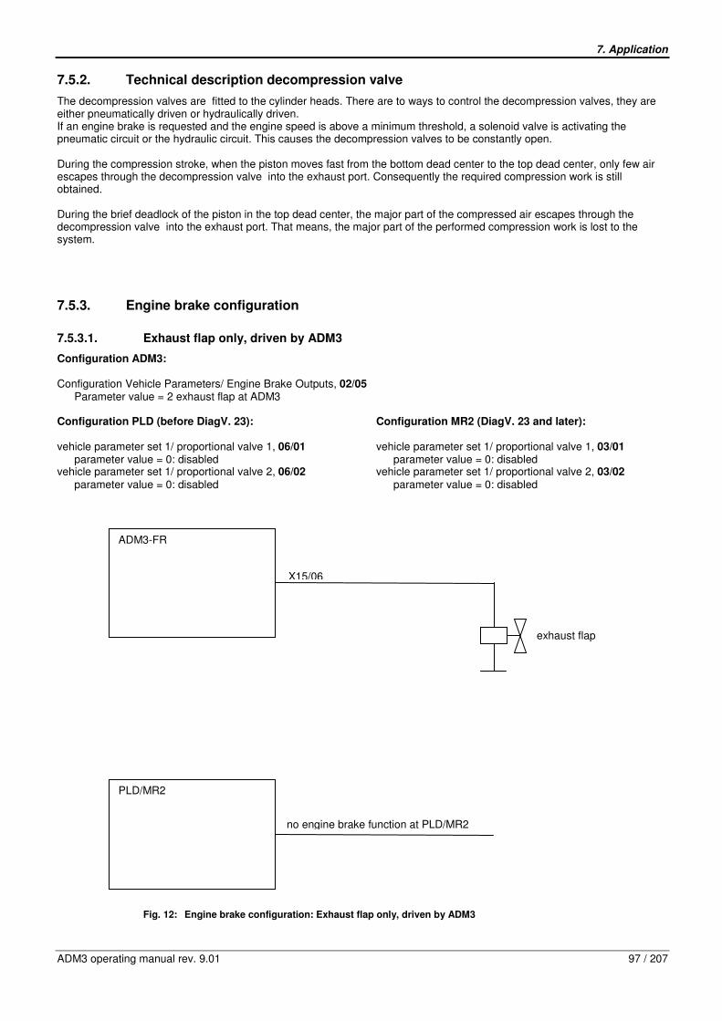
7. Application
ADM3 operating manual rev. 9.01 97 / 207
7.5.2. Technical description decompression valve
The decompression valves are fitted to the cylinder heads. There are to ways to control the decompression valves, they are either pneumatically driven or hydraulically driven. If an engine brake is requested and the engine speed is above a minimum threshold, a solenoid valve is activating the pneumatic circuit or the hydraulic circuit. This causes the decompression valves to be constantly open. During the compression stroke, when the piston moves fast from the bottom dead center to the top dead center, only few air escapes through the decompression valve into the exhaust port. Consequently the required compression work is still obtained. During the brief deadlock of the piston in the top dead center, the major part of the compressed air escapes through the decompression valve into the exhaust port. That means, the major part of the performed compression work is lost to the system.
7.5.3. Engine brake configuration
7.5.3.1. Exhaust flap only, driven by ADM3
Configuration ADM3: Configuration Vehicle Parameters/ Engine Brake Outputs, 02/05
Parameter value = 2 exhaust flap at ADM3 Configuration PLD (before DiagV. 23): vehicle parameter set 1/ proportional valve 1, 06/01
parameter value = 0: disabled vehicle parameter set 1/ proportional valve 2, 06/02
parameter value = 0: disabled
Configuration MR2 (DiagV. 23 and later): vehicle parameter set 1/ proportional valve 1, 03/01
parameter value = 0: disabled vehicle parameter set 1/ proportional valve 2, 03/02
parameter value = 0: disabled
Fig. 12: Engine brake configuration: Exhaust flap only, driven by ADM3
ADM3-FR
PLD/MR2
X15/06
no engine brake function at PLD/MR2
exhaust flap

7. Application
98 / 207 ADM3 operating manual rev. 9.01
7.5.3.2. Exhaust flap only, exhaust flap at PLD/MR2
Configuration ADM3: Configuration Vehicle Parameters / Engine Brake Outputs, 02/05
Parameter value = 0: disabled Configuration PLD (before DiagV. 23): vehicle parameter set 1/ proportional valve 1, 06/01
parameter value = 3: exhaust flap at proportional valve 1 vehicle parameter set 1/ proportional valve 2, 06/02
parameter value = 0: disabled
Configuration MR2 (DiagV. 23 and later): vehicle parameter set 1/ proportional valve 1, 03/01
parameter value = 3: exhaust flap at proportional valve 1 vehicle parameter set 1/ proportional valve 2, 03/02
parameter value = 0: disabled
Fig. 13: Engine brake configuration: Exhaust flap only, exhaust flap at PLD/MR2
7.5.3.3. Decompression valve only, decompression valve at ADM3
Configuration ADM3: Configuration Vehicle Parameters / Engine Brake Outputs, 02/05
parameter value =3 decompression valve at ADM3 Configuration PLD (before DiagV. 23): vehicle parameter set 1/ proportional valve 1, 06/01
parameter value = 0: disabled vehicle parameter set 1/ proportional valve 2, 06/02
parameter value = 0: disabled
Configuration MR2 (DiagV. 23 and later): vehicle parameter set 1/ proportional valve 1, 03/01
parameter value = 0: disabled vehicle parameter set 1/ proportional valve 2, 03/02
parameter value = 0: disabled
ADM3-FR
PLD/MR2
no engine brake function at ADM3-FR
X 55/51
solenoid valve for exhaust flap
X 55/12
PV 1

7. Application
ADM3 operating manual rev. 9.01 99 / 207
Fig. 14: Engine brake configuration: Decompression valve only, decompression valve at ADM3
7.5.3.4. Exhaust flap and decompression valve at one valve
Configuration ADM3: Configuration Vehicle Parameters / Engine Brake Outputs, 02/05
parameter value =1 exhaust flap and decompression valve at one valve Configuration PLD (before DiagV. 23): vehicle parameter set 1/ proportional valve1, 06/01
parameter value = 0: disabled vehicle parameter set 1/ proportional valve2, 06/02
parameter value = 0: disabled
Configuration MR2 (DiagV. 23 and later): vehicle parameter set 1/ proportional valve1, 03/01
parameter value = 0: disabled vehicle parameter set 1/ proportional valve2, 03/02
parameter value = 0: disabled
ADM3-FR
PLD/MR2
no engine brake function at PLD/MR2
decompression valve
X 15/10

7. Application
100 / 207 ADM3 operating manual rev. 9.01
Fig. 15: Engine brake configuration: Exhaust flap and decompression valve at one valve
7.5.3.5. Exhaust flap und decompression valve at two separate valves
7.5.3.5.1. Exhaust flap und decompression valve at ADM3
Configuration ADM3: Configuration Vehicle Parameters / Engine Brake Outputs, 02/05
parameter value =4 exhaust flap and decompression valve at ADM3 Configuration PLD (before DiagV. 23): vehicle parameter set 1/ proportional valve1, 06/01
parameter value = 0: disabled vehicle parameter set 1/ proportional valve2, 06/02
parameter value = 0: disabled
Configuration MR2 (DiagV. 23 and later): vehicle parameter set 1/ proportional valve1, 03/01
parameter value = 0: disabled vehicle parameter set 1/ proportional valve2, 03/02
parameter value = 0: disabled
ADM3-FR
PLD/MR2
no engine brake function at PLD/MR2
solenoid valve for exhaust flap and decompression valve
X 15/06

7. Application
ADM3 operating manual rev. 9.01 101 / 207
Fig. 16: Engine brake configuration: Exhaust flap and decompression valve at two separate valves
7.5.3.5.2. Exhaust flap at ADM3 and decompression valve at PLD/MR2
Configuration ADM3: Configuration Vehicle Parameters / Configuration Engine Brake , 02/05
parameter value =2 exhaust flap at ADM3 Configuration PLD (before DiagV. 23): vehicle parameter set 1/ proportional valve 1, 06/01
parameter value = 0: disabled vehicle parameter set 1/ proportional valve 2, 06/02
parameter value = 3: decompression valve at PLD
Configuration MR2 (DiagV. 23 and later): vehicle parameter set 1/ proportional valve 1, 03/01
parameter value = 0: disabled vehicle parameter set 1/ proportional valve 2, 03/02
parameter value = 3: decompression valve at PLD
ADM3-FR
PLD/MR2
no engine brake function at PLD/MR2
decompression valve
X 15/10
exhaust flap
X 15/06

7. Application
102 / 207 ADM3 operating manual rev. 9.01
Fig. 17: Engine brake configuration: Exhaust flap at ADM3 and decompression valve at PLD/MR2
7.5.3.5.3. Exhaust flap and decompression valve at PLD/MR2
Configuration ADM3: Configuration Vehicle Parameters / Configuration Engine Brake , 02/05
parameter value = 0 no engine brake at ADM3 Configuration PLD (before DiagV. 23): vehicle parameter set 1/ proportional valve 1, 06/01
parameter value = 3: exhaust flap at PLD vehicle parameter set 1/ proportional valve 2, 06/02
parameter value = 3: decompression valve at PLD
Configuration MR2 (DiagV. 23 and later): vehicle parameter set 1/ proportional valve 1, 03/01
parameter value = 3: exhaust flap at PLD vehicle parameter set 1/ proportional valve 2, 03/02
parameter value = 3: decompression valve at PLD
ADM3-FR
PLD/MR2
solenoid valve for exhaust flap
X 55/52
solenoid valve for decompression valve
X 15/06
X 55/50
PV 2
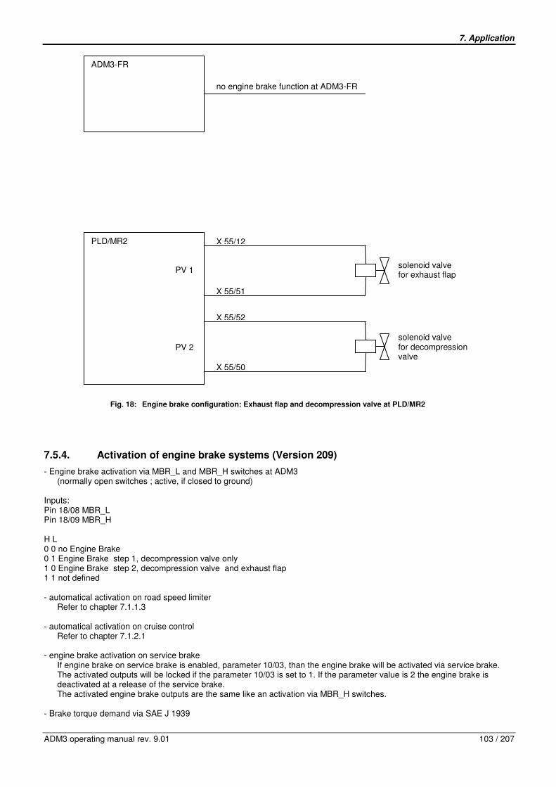
7. Application
ADM3 operating manual rev. 9.01 103 / 207
Fig. 18: Engine brake configuration: Exhaust flap and decompression valve at PLD/MR2
7.5.4. Activation of engine brake systems (Version 209)
- Engine brake activation via MBR_L and MBR_H switches at ADM3 (normally open switches ; active, if closed to ground)
Inputs: Pin 18/08 MBR_L Pin 18/09 MBR_H H L 0 0 no Engine Brake 0 1 Engine Brake step 1, decompression valve only 1 0 Engine Brake step 2, decompression valve and exhaust flap 1 1 not defined - automatical activation on road speed limiter
Refer to chapter 7.1.1.3 - automatical activation on cruise control
Refer to chapter 7.1.2.1 - engine brake activation on service brake
If engine brake on service brake is enabled, parameter 10/03, than the engine brake will be activated via service brake. The activated outputs will be locked if the parameter 10/03 is set to 1. If the parameter value is 2 the engine brake is deactivated at a release of the service brake. The activated engine brake outputs are the same like an activation via MBR_H switches.
- Brake torque demand via SAE J 1939
ADM3-FR
PLD/MR2
X 55/52
solenoid valve for exhaust flap
no engine brake function at ADM3-FR
X 55/12
PV 2 solenoid valve for decompression valve
PV 1
X 55/51
X 55/50

7. Application
104 / 207 ADM3 operating manual rev. 9.01
7.5.5. Deactivation of engine brake
- engine speed below value parameter 10/01, minimum engine speed MBR - Accelerator pedal further pushed down than maximum throttle position for engine brake,
parameter 10/02 - Vehicle speed below minimum road speed for engine brake operation,
parameter 10/04
- if cruise control active Refer to chapter 7.1.2
- if PTO speed control active
Refer to chapter 7.2 - engine brake lock out via SAE J 1939 - engine brake deactivation on release of service brake
If engine brake on service brake is enabled, parameter 10/03 is set to 2, than the engine brake will be deactivated when the service brake is released.
7.5.6. Engine brake operation with a stalk switch
As already described in chapter 7.1.2.2. the mentioned stalk switch includes one step High for engine brake operation. With lever position 3 (compare figure in chapter 7.1.2.2.) 18/09 is switched to ground, hence activating stage 2. The engine brake configuration is set by parameter 10/13. The stage mask and its factor for stage 2 is set by the parameters 10/16 and 10/17 respectively. When a turbo brake is not used the default value of parameter 10/16 (Engine Brake Stage 2 Mask = 80) needs not to be changed. Input values: – Pin 18/09 MBR_H Parameters from parameter group 10:
Nr. Parameter Description
13 Engine Brake Configuration
Type of engine brake system
Parameter values: 0 = compression brake and exhaust flap 1 = compression brake and turbo brake
16 Engine Brake Stage 2 Mask
Engine brake activation if MBR_L=0 and MBR_H=1
Parameter values: 0 = no activation 64 = decompression valve (stage 1) 80 = decompression valve and exhaust flap (stage 2) 81 = decompression valve ,exhaust flap and turbo brake (stage 3)
17 Engine Brake Stage 2 Factor
Turbo brake torque demand relative value
If parameter 10/16 = 81 then parameter 10/17 can be set from 0 to 100% for turbo brake demand else parameter 10/17 has to be set on value 100%

7. Application
ADM3 operating manual rev. 9.01 105 / 207
7.6. Instruments / Displays
7.6.1. Rev counter
A signal for actuating a rev counter is provided at the output "N_MOT"(engine speed). Input values: – Engine speed information from PLD/MR2 via CAN connection Parameter: – 09/04 Engine speed display (Output N_MOT) Output: – Pin 12/06 N_MOT
7.6.2. Coolant temperature gauge
A signal which is compatible with temperature sensors is provided at the output "T_MOT"(coolant temperature) for connecting up a conventional analogue indicator instrument. Input values: –Coolant temperature information from PLD/MR2 via CAN connection Parameter: – 09/04 Coolant temperature Display (Output T_MOT) Output: – Pin 12/04 T_MOT
7.6.3. Oil pressure gauge
A signal which is compatible with oil pressure sensors is provided at the output "P_OEL"(oil pressure) for connecting up a conventional analogue indicator instrument. Input values: – Oil pressure information from PLD/MR2 via CAN connection Parameter: – 09/03 Oil pressure display (Output P_OEL) Output: – Pin 12/03 P_OEL
7.6.4. Coolant temperature indicator lamp
The output "T_MOT" (coolant indicator lamp) reports impermissibly high coolant temperatures. Here, the output "LA_ADM" (warning lamp) is actuated. The temperature limit is stored in the engine data records.
7. Application
106 / 207 ADM3 operating manual rev. 9.01
Input values: – CAN information "Coolant temperature too high" from PLD/MR2 Parameter: - 09/04 Coolant temperature display (Output T_MOT) Outputs: – Pin 12/04 T_MOT – Pin 21/06 LA_ADM
7.6.5. Oil pressure indicator lamp
The output "P_OEL" (oil pressure indicator lamp) reports impermissibly low oil pressures. Here, the output "LA_ADM" (warning lamp) is actuated. The oil pressure limit is stored in the engine data records. Input value: – CAN information "Oil pressure too low“ from PLD/MR2 Parameter: – 09/03 Oil pressure display (Output P_OEL) Outputs: – Pin 12/03 P_OEL – Pin 21/06 LA_ADM
7.6.6. Oil level indicator lamp
The output "LA_OELST" (oil level indicator lamp) reports impermissibly low oil levels. Here, the output "LA_ADM"(warning lamp) is actuated. The function "Oil level warning" is only available on engines with oil level sensor. The oil level limit is stored in the engine data records. Beginning with diagnosis version 209 the oil level indicator lamp may also be used for indicating engine overspeed. Depending on the value of parameter 18/13 (Oil Level Lamp Configuration, compare chapters 4.1.18 and 4.2.18) the oil level indicator lampe reports following warnings: 0 (Oil Level): If the oil level is too low, the lamp will be illuminated, if the oil level is very low, the lamp will be flashing, 1 (Engine Overspeed): If the current engine speed is above the maximum speed, the lamp will be illuminated, 2 (Oil Level or Engine Overspeed): The conditions of case 0 and 1 are combined, flashing has higher priority than illuminating Input values: – CAN information "Oil level too low" from PLD/MR2 – Current Engine Speed from PLD/MR2 Parameters: – 18/11 (Overspeed BR 500) or 18/12 (Overspeed BR 900) depending on the engine type – 18/13 Oil Level Lamp Configuration Outputs: – Pin 21/04 LA_OELST – Pin 21/06 LA_ADM

7. Application
ADM3 operating manual rev. 9.01 107 / 207
7.6.7. Configuration Indicator lamp and gauge
There are applications where it is necessary to have a indicator lamp and a gauge for Oil pressure and/or Coolant temperature. Therefore it is possible to use Output REL3 and/or REL4 to drive the Oil pressure indicator lamp and/or the Coolant temperature indicator lamp. Output REL3 is configured via parameter 14/01 IWK3 and output REL4 is configured via parameter 14/10 IWK4. In this configuration the outputs P_OEL and/or T_MOT are still available for the Oil pressure gauge and/or Coolant temperature gauge. Refer to chapter 7.6.4 and 7.6.5. Parameter: - 09/03 Oil pressure display (Output P_OEL) - 09/04 Coolant temperature display (Output T_MOT) - 14/01 Configuration (IWK3) Actual Value Comparator 3 - 14/11 Configuration (IWK4) Actual Value Comparator 4 Outputs: - Pin 12/03 P_OEL - Pin 12/04 T_MOT - Pin 15/11 REL3 - Pin 18/01 REL4
7.6.8. Grid Heater indicator lamp
The Grid Heater indicator lamp indicates an active cold start device. As long as the indicator lamp is active, the engine should not be started. The inputs DSF0 and DSF1 can be used to monitor the Grid Heater states. Input values: – CAN information "Cold Start device active" from PLD/MR2 Inputs: - Pin 12/10 DSF0 - PIN 12/09 DSF1 Parameter: - 02/07 Relay 2 - 13/06 Configuration variable inputs DSF0 - 13/07 Configuration variable inputs DSF1 Outputs: – Pin 21/07 LA_GRID
7.6.9. Air filter indicator lamp
An air filter sensor is connected to the input LF_SE. The air filter sensor is sensing the differential pressure. If the air filter needs to be changed, the output LA_LUFT for the air filter indicator lamp will be active. Power supply: - Pin 18/17 HFG+, power supply remote throttle or air filter sensor - Pin 21/03 KL 31, ground Inputs: - Pin 15/08 LF_SE, Air Filter Sensor

7. Application
108 / 207 ADM3 operating manual rev. 9.01
Outputs: – Pin 21/08 LA_LUFT
7.6.10. Check engine lamp
The output "LA_ADM"(check engine lamp) reports impermissible engine operating states (e.g. oil pressure too low) and active faults which are recognized by the control unit due to the permanent monitoring of the inputs and outputs.
The output "LA_ADM" must be connected to a suitable warning lamp. If the warning lamp lights up while the engine is in operation, both the engine and the electronics must be examined.
The output "LA_ADM" is actuated if the following faults are detected: – Coolant temperature too high or temperature signal not available – Oil pressure too low or oil pressure signal not available – Oil level too low
Stop the engine immediately if the coolant temperature is too high, the oil pressure too low or the oil level too low. The operating safety of the engine is endangered (risk of engine damage).
– No CAN connection to engine electronics PLD/MR2 or CAN data implausible – Active faults in PLD/MR2 engine management fault memory, fault priority medium or high – Active faults in ADM3-FR fault memory, fault priority medium or high Input values: – Engine speed information from PLD/MR2 via CAN connection – CAN information "Coolant temperature too high“ from PLD/MR2 – CAN information "Oil pressure too low“ from PLD/MR2 – CAN information "Oil level too low“ from PLD/MR2 – CAN information "Active fault in PLD/MR2 engine management" with fault priority medium or high – Active fault in ADM3-FR, fault priority medium or high – CAN information "Buzzer instruction" Parameters: - 17/01 Enable idle shutdown - 17/06 Warning period check engine light - 18/01 Engine temperature - 18/02 Coolant level - 18/03 Oil pressure - 18/04 Oil level - 18/08 Warning period for check engine light Output: – Pin 21/06 LA_ADM
7.6.11. Stop engine lamp / Buzzer
The output "LA_STOP" reports serious faults which require the engine to be switched off immediately. Failure to switch the engine off could result in major damage to the engine, possibly even its destruction. The output "LA_STOP" must be connected. A warning buzzer or warning lamp can be connected.

7. Application
ADM3 operating manual rev. 9.01 109 / 207
Input values: CAN instruction "Buzzer“ from PLD/MR2 in the event of: – Overspeeding – Oil level impermissibly low – Oil pressure impermissibly low – Coolant temperature impermissibly high The limits for the values listed above are stored in the engine data records. The sensors for Oil level, Oil pressure and Coolant temperature are connected to the PLD/MR2. Instruction "Buzzer“ from ADM3 in the event of: – Coolant level impermissibly low The sensor for Coolant level is connected to the ADM3. Parameters: - 17/01 Enable idle shutdown - 17/07 Warning period stop engine light - 18/01 Engine temperature - 18/02 Coolant level - 18/03 Oil pressure - 18/04 Oil level - 18/09 Warning period stop engine light Output: – Pin 21/05 LA_STOP

7. Application
110 / 207 ADM3 operating manual rev. 9.01
7.7. Actual value output IWA
The actual value output is provided in the form of PWM signal at the output "IWA"(actual value output) to incorporate customer-specific electronic systems. The physical value output at IWA can be selected. Pulse duty factors < 5% and >95% are evaluated as faults or as signal failures by the subsequent electronic circuit connected. Parameter: - 09/01 Actual value output IWA Output: – Pin 15/05 IWA
Nr. Parameter Description
01
Configuration Analog Output (IWA)
Refer to chapter 7.7 for further information about the function IWA
Parameter values: 0 = disabled 1 = throttle torque 10..90% 2 = Difference torque (external load control) 3 = throttle torque 90..10% 4 = actual torque 5 = load torque (no idle torque for automatic transmission) 6 = road speed 7 = demand speed 8 = demand speed CC+/- 9 = AGS2 transmission Temp indication lamp off 10 = AGS2 transmiss. Temp indication lamp on 11 = AdBlue level 10 – 90%
The physical value output at IWA can be selected. Pulse duty factors < 5% and >95% are evaluated as faults or as signal failures by the subsequent electronic circuit connected.
Value Meaning Remarks
0
1 Throttle torque (10% .. 90%)
Indication of accelerator pedal position idle - full throttle to 10 % .. 90 % pulse duty factor.
2 Differential torque (limit load signal)
Signal for engine load evaluation e.g. for limit load control 90%: Maximum engine torque reached (drive) 50%: Engine not under load 10%: Maximum friction torque reached
3 Throttle torque inverted (10% .. 90%)
Indication of accelerator pedal position idle - full throttle to 90 % .. 10 % pulse duty factor.
4 Actual torque Indication of the actual engine torque 0 .. Mdmax to 10 % .. 90% pulse duty factor
5 Load signal
Load signal for coupling an automatic transmission with PWM interface. Output value is the minimum of the active torque and set torque, which is calculated on the basis of a maximum value generation of the accelerator pedal demand and the cruise control demand
6 Road speed
Formation of an C3 signal for other electronics.
]ms[
1000*45,0]km/h[
FZGt
v =
t = periodic time of signal (with T = 2ms = constant = pulse period)
7 Nominal speed Indication of the currently active nominal speed during PTO mode to 10% .. 90% pulse duty factor
8 Demand speed CC +/-
Special function for crawler-vehicles. Cruise control function with CC+ / CC- Demand speedoutput on pin 12/05
9
AGS2 transmission temp indication lamp off
10
AGS2 transmission temp indication lamp on
11 AdBlue Level Indication of the AdBlue tank level. 10% PWM = AdBlue tank is empty 90% PWM = AdBlue tank is full

7. Application
ADM3 operating manual rev. 9.01 111 / 207
7.8. Speed Signal
For the realization of the functions –Legal maximum speed –Programmable maximum speed The speed signal C3/B7 of a tachograph has to be connected to input C3 (tachograph speed) of the ADM-FR. The input C3 is monitored for a short or open circuit. If the speed signal C3/B7 is not available, a square-wave sensor can be connected to the input C3 instead. Refer to chapter 7.8.2. The Transmission output shaft speed via SAE J1939 can also be used to generate a vehicle speed information. Refer to chapter 7.8.3. The appropriate vehicle speed information source has to be set in parameter 08/02, speed sensor. For applications without speed signal, the ADM-FR speed measurement function must be deactivated by appropriate parameter programming, parameter 08/02.
Parameter programming of the maximum speed (legal maximum speed) and the deactivation of the speed measurement is only possible with special authorization. Such authorization can be issued to vehicle manufacturers upon application to Daimler. Due to European legal regulations the Speed Sensor type in parameter 08/02 can only be set to the systems 1 or 5, which are approved as calibrated systems for on-highway applications in Europe. If it is desired to change the parameter to another type (or no sensor) for use in off-highway applications or in countries outside Europe, a special password for MiniDiag is necessary.
Parameters: – 08/02 Speed Sensor – 03/03 Maximum road speed (legal) – 05/03 Maximum road speed LIM0 – 05/07 Maximum road speed LIM1 – 06/05 Maximum road speed KLIMA Output value: – Maximum Speed via required torque to PLD/MR2 via CAN connection
7.8.1. Tachograph (C3, B7)
The speed signal C3/B7 of a tachograph has to be connected to input C3 (tachograph speed) of the ADM-FR. The input C3 is monitored for a short or open circuit. Inputs: - Pin 15/03 C3/B7 C3 speed signal - Pin 18/11 LIM0 - Pin 18/12 LIM1 - Pin 18/14 KLIMA Parameters: – 08/02 Speed Sensor – 03/03 Maximum road speed (legal) – 05/03 Maximum road speed LIM0 – 05/07 Maximum road speed LIM1 – 06/05 Maximum road speed KLIMA Output value: – Maximum Speed via required torque to PLD/MR2 via CAN connection
7. Application
112 / 207 ADM3 operating manual rev. 9.01
7.8.2. Square-wave Sensor
If the speed signal C3/B7 is not available, a square-wave sensor can be connected to the input C3 instead. The square-wave sensor is sensing the Transmission output shaft speed. Therefore the parameter group 22 has to be applied. Inputs: - Pin 15/03 C3/B7 square-wave sensor - Pin 18/11 LIM0 - Pin 18/12 LIM1 - Pin 18/14 KLIMA Parameters: - 08/02 Speed Sensor - 03/03 Maximum road speed (legal) - 05/03 Maximum road speed LIM0 - 05/07 Maximum road speed LIM1 - 06/05 Maximum road speed KLIMA - 22/01 Axle ratio - 22/02 Number of teeth - 22/03 Tire revolutions - 22/04 Gear ratio - 22/05 2. Axle ratio Output value: – Maximum Speed via required torque to PLD/MR2 via CAN connection
7.8.3. Transmission output shaft speed via SAE J1939
If the speed signal C3/B7 is not available, the Transmission output shaft speed via SAE J1939 can also be used to generate a vehicle speed information. Therefore the parameter group 22 has to be applied. Input value: - Transmission output shaft speed via SAE J1939 (PGN 61442) Inputs: - Pin 18/11 LIM0 - Pin 18/12 LIM1 - Pin 18/14 KLIMA Parameters: - 08/02 Speed Sensor - 03/03 Maximum road speed (legal) - 05/03 Maximum road speed LIM0 - 05/07 Maximum road speed LIM1 - 06/05 Maximum road speed KLIMA - 22/01 Axle ratio - 22/02 Number of teeth - 22/03 Tire revolutions - 22/04 Gear ratio - 22/05 2. Axle ratio Output value: – Maximum Speed via required torque to PLD/MR2 via CAN connection
7. Application
ADM3 operating manual rev. 9.01 113 / 207
7.8.4. Inductive Sensor
If the speed signal C3/B7 is not available, a inductive sensor can be connected to the input C3 instead. The inductive sensor is sensing the Transmission output shaft speed. Therefore the parameter group 22 has to be applied. Inputs: - Pin 15/03 C3/B7 inductive sensor - Pin 18/11 LIM0 - Pin 18/12 LIM1 - Pin 18/14 KLIMA Parameters: - 08/02 Speed Sensor - 03/03 Maximum road speed (legal) - 05/03 Maximum road speed LIM0 - 05/07 Maximum road speed LIM1 - 06/05 Maximum road speed KLIMA - 22/01 Axle ratio - 22/02 Number of teeth - 22/03 Tire revolutions - 22/04 Gear ratio - 22/05 2. Axle ratio Output value: – Maximum Speed via required torque to PLD/MR2 via CAN connection
7.8.5. J1939 (TCO1) Message
If the speed signal C3/B7 is not available, the transmission output shaft speed and vehicle speed may be provided by the tachograph via the SAE J1939 message TCO1. If the parameter 08/02 is set to 5, then the transmission output shaft speed and the vehicle speed are derived from the TCO1 message. Input value: - Transmission output shaft speed and vehicle speed via SAE J1939 (PGN 65132) Inputs: - Pin 18/11 LIM0 - Pin 18/12 LIM1 - Pin 18/14 KLIMA Parameters: - 08/02 Speed Sensor - 03/03 Maximum road speed (legal) - 05/03 Maximum road speed LIM0 - 05/07 Maximum road speed LIM1 - 06/05 Maximum road speed KLIMA - 22/01 Axle ratio - 22/02 Number of teeth - 22/03 Tire revolutions - 22/04 Gear ratio - 22/05 2. Axle ratio Output value: – Maximum Speed via required torque to PLD/MR2 via CAN connection

7. Application
114 / 207 ADM3 operating manual rev. 9.01
7.9. Limitations
7.9.1. Common Limitations
Common limitations are active in both driving mode and working speed governor mode. The maximum values effective in parameter group 3, Common Limiters, or in the engine electronics can only be superseded by lower values, the minimum values only be higher values. Refer to Programmable Limitations chapter 7.9.2. Parameters: - 03/01 Minimum engine speed - 03/02 Maximum engine speed - 03/03 Maximum road speed - 03/04 Maximum engine torque
7.9.2. Programmable Limitations
The inputs LIM0, LIM1 or KLIMA can be used to realize programmable limitations. The following limitations can be realized when the input is active: – Idling speed boost e.g. when the air conditioner is switched on – Maximum engine speed limitation e.g. for pumps or other power take-off. – Vehicle speed limitation e.g. for road sweepers or refuse collection trucks in working mode – Maximum torque limitation e.g. as overload protection for power take-off, transmission etc. Programmed limitations are active in both driving mode and working speed governor mode. The maximum values effective in parameter group 3, Common Limiters, or in the engine electronics can only be superseded by lower values, the minimum values only be higher values. Inputs: - Pin 18/11 LIM0 - Pin 18/12 LIM1 - Pin 18/14 KLIMA Parameters: - 05/01 Minimum engine speed LIM0 - 05/02 Maximum engine speed LIM0 - 05/03 Maximum road speed LIM0 - 05/04 Maximum engine torque LIM0 - 05/05 Minimum engine speed LIM1 - 05/06 Maximum engine speed LIM1 - 05/07 Maximum road speed LIM1 - 05/08 Maximum engine torque LIM1 - 06/03 Minimum engine speed KLIMA - 06/04 Maximum engine speed KLIMA - 06/05 Maximum road speed KLIMA - 06/06 Maximum engine torque KLIMA
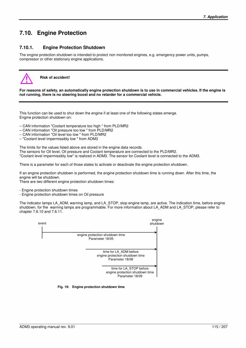
7. Application
ADM3 operating manual rev. 9.01 115 / 207
7.10. Engine Protection
7.10.1. Engine Protection Shutdown
The engine protection shutdown is intended to protect non monitored engines, e.g. emergency power units, pumps, compressor or other stationary engine applications.
Risk of accident!
For reasons of safety, an automatically engine protection shutdown is to use in commercial vehicles. If the engine is not running, there is no steering boost and no retarder for a commercial vehicle.
This function can be used to shut down the engine if at least one of the following states emerge. Engine protection shutdown on: – CAN information "Coolant temperature too high " from PLD/MR2 – CAN information "Oil pressure too low " from PLD/MR2 – CAN information "Oil level too low " from PLD/MR2 – "Coolant level impermissibly low " from ADM3 The limits for the values listed above are stored in the engine data records. The sensors for Oil level, Oil pressure and Coolant temperature are connected to the PLD/MR2. "Coolant level impermissibly low" is realized in ADM3. The sensor for Coolant level is connected to the ADM3. There is a parameter for each of those states to activate or deactivate the engine protection shutdown. If an engine protection shutdown is performed, the engine protection shutdown time is running down. After this time, the engine will be shutdown. There are two different engine protection shutdown times: - Engine protection shutdown times - Engine protection shutdown times on Oil pressure The indicator lamps LA_ADM, warning lamp, and LA_STOP, stop engine lamp, are active. The indication time, before engine shutdown, for the warning lamps are programmable. For more information about LA_ADM and LA_STOP, please refer to chapter 7.6.10 and 7.6.11.
Fig. 19: Engine protection shutdown time
engine shutdown event
engine protection shutdown time Parameter 18/05
time for LA_ADM before engine protection shutdown time
Parameter 18/08
time for LA_STOP before engine protection shutdown time
Parameter 18/09
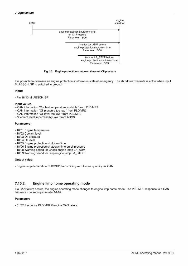
7. Application
116 / 207 ADM3 operating manual rev. 9.01
Fig. 20: Engine protection shutdown times on Oil pressure
It is possible to overwrite an engine protection shutdown in state of emergency. The shutdown overwrite is active when input M_ABSCH_SP is switched to ground. Input: - Pin 18/13 M_ABSCH_SP Input values: – CAN information "Coolant temperature too high " from PLD/MR2 – CAN information "Oil pressure too low " from PLD/MR2 – CAN information "Oil level too low " from PLD/MR2 – "Coolant level impermissibly low " from ADM3 Parameters: - 18/01 Engine temperature - 18/02 Coolant level - 18/03 Oil pressure - 18/04 Oil level - 18/05 Engine protection shutdown time - 18/06 Engine protection shutdown time on oil pressure - 18/08 Warning period for Check engine lamp LA_ADM - 18/09 Warning period for Stop engine lamp LA_STOP Output value: - Engine stop demand on PLD/MR2, transmitting zero torque quantity via CAN
7.10.2. Engine limp home operating mode
If a CAN failure occurs, the engine operating mode changes to engine limp home mode. The PLD/MR2 response to a CAN failure can be set in parameter 01/02. Parameter: - 01/02 Response PLD/MR2 if engine CAN failure
engine shutdown event
engine protection shutdown time on Oil Pressure
Parameter 18/06
time for LA_ADM before engine protection shutdown time
Parameter 18/08
time for LA_STOP before engine protection shutdown time
Parameter 18/09

7. Application
ADM3 operating manual rev. 9.01 117 / 207
7.11. Cold start with grid heater
The ADM3 provides an integrated function for the control of an electric grid heater. The grid heater is positioned directly in the air suction channel. The Mercedes-Benz grid heater has a heater output of approx. 2 kW. Inputs: - Pin 12/10, digital special function 0 (DSF 0) input switched to battery voltage - Pin 12/09, digital special function 1 (DSF 1) input switched to ground Outputs: -Pin 15/09, REL2, control relay 2, output switched to ground -Pin 21/07, LA_GRID, warning lamp grid heater Wiring: The output REL 2 (Pin 15/09) controls the high-load relay of the grid heater. The input DSF0 (with a load relay switched to battery voltage) or the DSF1 (with a load relay switched to ground)can be used for monitoring the normally open contact of the high-load relay. The control of the Mercedes-Benz grid heater takes always place with a load relay switched to battery voltage. Parameters: The cold start function or the input for monitoring the high-load relay is activated by means of configuration. The temperature thresholds of the cold start function can to some degree be adapted with parameter 02/14. For example in the case of an additional use of a block heater. - 02/07 configuration relay 2:
parameter value 1 = grid heater - 13/06 input DSF0:
parameter value 4 = monitoring grid heater - 13/07 input DSF1:
parameter value 4 = monitoring grid heater - 02/14 temperature correction block heater
parameter value > 0 = The switch-on threshold of the grid heater is shifted to “warmer”. Function: The cold start function is an automatic flow control, which passes through the following statuses upon switching on the terminal 15/09:
Status Explanation
0: Initialization
Upon switching on terminal 15/09 and depending on the actual coolant- and charge air temperature, the ADM3 decides if a cold start support is necessary for an engine start . If that is not the case, it is continued with status 26. Otherwise with status1, preheating.
The warning lamp “grid heater” is controlled for a period of approx. 2 seconds (lamp testing).
1: Preheating (max. 30 s)
Warning lamp and grid heater relay are controlled. The starting of the engine leads to the immediate abortion of the cold start process (status 36).
The warning lamp “grid heater“ goes out at the end of the preheating period: The engine is ready to start.
2: Ready to start If no engine start takes place (engine speed zero) within 20 seconds, abortion (46), otherwise it is continued with start (3).
3: Start If the engine start is successful, it is continued with (4) otherwise (66).
4: Post-heating Post-heating when the engine is already running, in order to improve the emission levels.
5: Cooling Deactivation of grid heater
6: End Cold start has been finished successfully.
16: Abortion due to the monitoring with DSF0 and DSF1.
Abortion of cold start due to the monitoring with DSF0 and DSF1: contact load relay fixed in closed position/interrupted or diagnostic line DSF0/DSF1 interrupted/shorted.
26: End No cold start is required, because the engine or the environment is too warm.

7. Application
118 / 207 ADM3 operating manual rev. 9.01
Status Explanation
36: Abortion during preheating Cold start abortion through the driver, due to an engine start during the preheating.
46: Exceeding of the time provided during start Cold start abortion, because no engine start takes place within 20 seconds.
56: Failure during start Cold start abortion, due to general failure (voltage supply, communication, etc.)
66: Exceeding of time provided during start Abortion of engine start, because no engine start takes place within 40 seconds
76: Failure during start Abortion during of the cold start, due to general failure (supply voltage, communication, etc.)
86: Failure during post-heating Abortion of cold start, due to general failure (voltage supply, communication, etc.)
96: No increase of charge air during post-heating Abortion, because no temperature increase of the charge air temperature can be measured
Note: There is no functional difference between the status 6, 16, ... 96, because the cold start procedure has already been terminated. The distinction between the different statuses have only been introduced for diagnostic purposes and they make it possible to draw conclusions from the course of the cold start function. (Refer to analog value 35, status of cold start function) Diagnostics: If the cold start function is active, the charge air temperature, the output relay 2 and - provided that it is configured - the load circuit of the relay are monitored. The corresponding fault codes are listed in the appendix.
The flashing of the warning lamp "grid heater" indicates a failure in the load circuit. In spite of an inactive output relay 2 - e.g. in the case of a contact fixed in closed position - an uncontrolled current feed of the grid heater can still take place. This failure can only be cleared by interrupting the grid heater power supply. Fire hazard exists, depending on the position of the grid heater or the engine!

7. Application
ADM3 operating manual rev. 9.01 119 / 207
7.12. Special functions
7.12.1. ABS
The ABS invention is deactivating the engine brake. An ABS intervention can be initialized over the configurable input DSF0 or DSF1, if the function is enabled by appropriate parameter, parameter 13/17 or 13/18, programming. An ABS invention can also be initialized via SAE J1939. The ABS is deactivating the engine brake via TSC1 by sending a torque limitation. Input value: – SAE J1939, TSC1 Request torque / torque limit Input: - Pin 12/10 DSF0 -Pin 12/09 DSF1 Parameter - 13/17 Configuration variable input DSF0 - 13/18 Configuration variable input DSF1
7.12.2. Conventional Retarder
The programmable input DSF0 or DSF1 is available for coupling a conventional retarder. When the input DSF0 or DSF1 is active, the information „Retarder intervention“ is transmitted to the engine control PLD/MR2. This setting only has a useful purpose on units on which the fan is controlled via the engine control PLD/MR2. A retarder intervention is deactivating an active Cruise Control. If Automatic Cruise Resume, parameter 15/07, is enabled, a retarder intervention via input DSF0 or DSF1 causes an active Cruise Control function to switch over to a stand by mode. Since the diagnosis version 203 it is possible to activate the fan by Retarder intervention via DSF0 or DSF1. This function is enabled by appropriate parameter programming. The parameter 19/13 is indicating the percentage of the fan power consumption if the input DSF0 is active, provided that the fan is demanded via the digital input DSF0 and DSF0 has been configured for retarder intervention. The parameter 19/14 is indicating the percentage of the fan power consumption if the input DSF1 is active, provided that the fan is demanded via the digital input DSF1 and DSF1 has been configured for retarder intervention. For further information about Automatic fan, pleas refer to chapter 7.12.3. Inputs: - Pin 12/10 DSF0 - Pin 12/09 DSF1 Parameters: - 13/17 Configuration variable input DSF0 - 13/18 Configuration variable input DSF1 - 19/13 DSF0 Fan - 19/14 DSF1 Fan - 19/11 Hold time Fan - 19/12 Ramp Fan - 15/07 Automatic Cruise Resume Output value: - Information "Retarder intervention" transmitting to the engine control PLD/MR2 via CAN
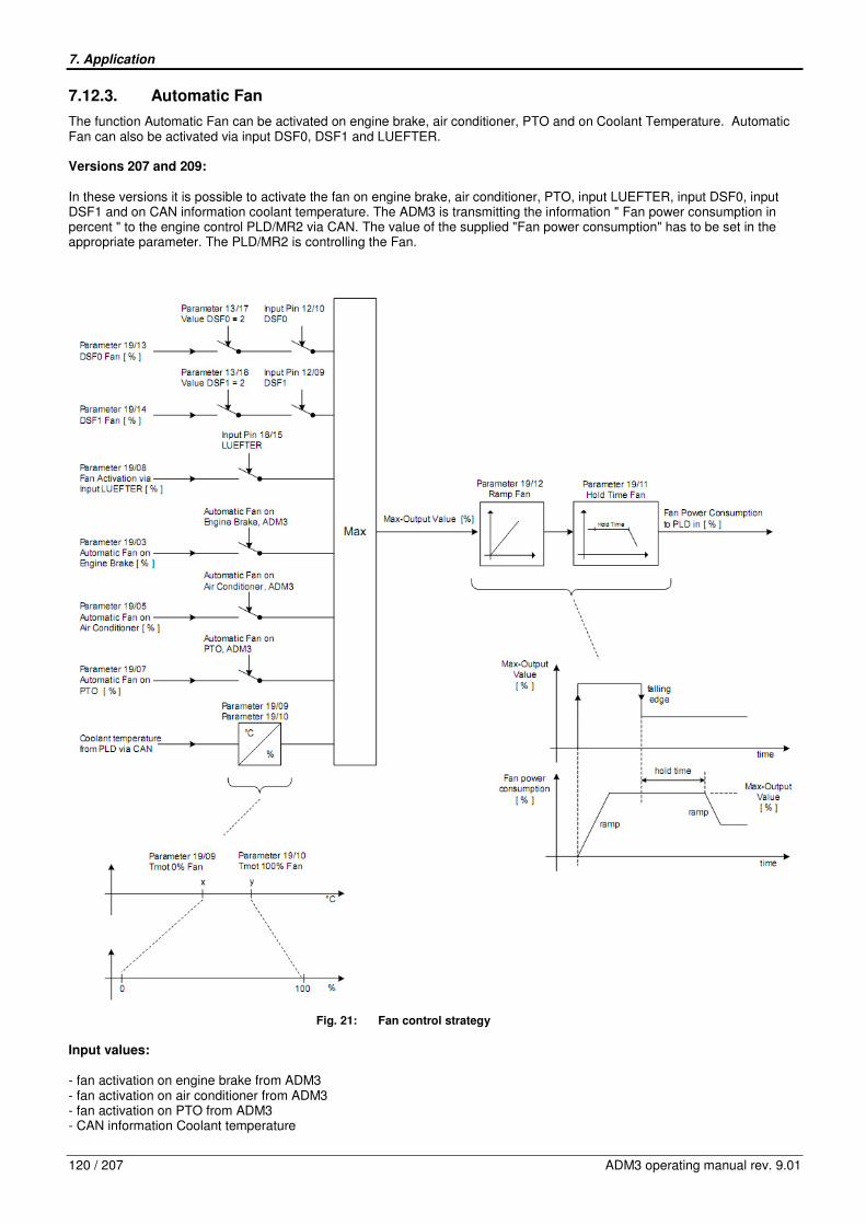
7. Application
120 / 207 ADM3 operating manual rev. 9.01
7.12.3. Automatic Fan
The function Automatic Fan can be activated on engine brake, air conditioner, PTO and on Coolant Temperature. Automatic Fan can also be activated via input DSF0, DSF1 and LUEFTER. Versions 207 and 209: In these versions it is possible to activate the fan on engine brake, air conditioner, PTO, input LUEFTER, input DSF0, input DSF1 and on CAN information coolant temperature. The ADM3 is transmitting the information " Fan power consumption in percent " to the engine control PLD/MR2 via CAN. The value of the supplied "Fan power consumption" has to be set in the appropriate parameter. The PLD/MR2 is controlling the Fan.
Fig. 21: Fan control strategy
Input values: - fan activation on engine brake from ADM3 - fan activation on air conditioner from ADM3 - fan activation on PTO from ADM3 - CAN information Coolant temperature

7. Application
ADM3 operating manual rev. 9.01 121 / 207
Inputs: - Pin 18/15 LUEFTER - Pin 12/10 DSF0 - Pin 12/09 DSF1 Parameters: Versions 207 and 209 - 19/01 Fan Type - 19/02 Enable automatic fan activation on engine brake - 19/03 Fan power on engine brake - 19/04 Enable automatic fan activation on air conditioner - 19/05 Fan power on air conditioner - 19/06 Enable automatic fan activation on PTO - 19/07 Fan power on PTO - 19/08 Fan power on fan override - 19/09 Coolant temperature at 0% fan - 19/10 Coolant temperature at 100% fan - 19/11 Hold time fan - 19/12 Ramp fan - 13/17 Configuration Variable Input DSF0 - 13/18 Configuration Variable Input DSF1 Output value: Versions 207 and 209 - Information "Fan power consumption in percent" transmitting to the engine control
PLD/MR2 via CAN
7.12.4. Accelerator pedal interlock
The input Pin 18/16 (FFG interlock) is provided for the function accelerator pedal interlock: Accelerator pedal (FFG) and remote accelerator pedal (HFG) are not effective, if the input is active. Inputs: - Pin 12/10, digital special function 0 (DSF 0) input switched to battery voltage - Pin 12/09, digital special function 1 (DSF 1) input switched to ground Outputs: -Pin 15/09, control relay 2, output switched to ground -Pin 21/07, LA_GRID, warning lamp grid heater Wiring: The output REL 2 (Pin 15/09) controls the high-load relay of the grid heater. The input DSF0 (with a load relay switched to battery voltage) or the DSF1 (with a load relay switched to ground)can be used for monitoring the normally open contact of the high-load relay. The control of the Mercedes-Benz grid heater takes always place with a load relay switched to battery voltage. Parameters: The cold start function or the input for monitoring the high-load relay is activated by means of configuration. The temperature thresholds of the cold start function can to some degree be adapted with parameter 02/14. For example in the case of an additional use of a block heater. - 02/03 configuration relay 2:
parameter value 1 = grid heater - 13/17 input DSF0:
parameter value 4 = monitoring grid heater

7. Application
122 / 207 ADM3 operating manual rev. 9.01
- 13/18 input DSF1: parameter value 4 = monitoring grid heater
- 02/07 temperature correction block heater parameter value > 0 = The switch-on threshold of the grid heater is shifted to “warmer”.
Function: The cold start function is an automatic flow control, which passes through the following statuses upon switching on the terminal 15/09:
Status Explanation
0: Initialization
Upon switching on terminal 15/09 and depending on the actual coolant- and charge air temperature, the ADM3 decides if a cold start support is necessary for an engine start . If that is not the case, it is continued with status 26. Otherwise with status1, preheating.
The warning lamp “grid heater” is controlled for a period of approx. 2 seconds (lamp testing).
1: Preheating (max. 30 s)
Warning lamp and grid heater relay are controlled. The starting of the engine leads to the immediate abortion of the cold start process (status 36).
The warning lamp “grid heater“ goes out at the end of the preheating period: The engine is ready to start.
2: Ready to start If no engine start takes place (engine speed zero) within 20 seconds, abortion (46), otherwise it is continued with start (3).
3: Start If the engine start is successful, it is continued with (4) otherwise (66).
4: Post-heating Post-heating when the engine is already running, in order to improve the emission levels.
5: Cooling Deactivation of grid heater
6: End Cold start has been finished successfully.
16: Abortion due to the monitoring with DSF0 and DSF1.
Abortion of cold start due to the monitoring with DSF0 and DSF1: contact load relay fixed in closed position/interrupted or diagnostic line DSF0/DSF1 interrupted/shorted.
26: End No cold start is required, because the engine or the environment is too warm.
36: Abortion during preheating Cold start abortion through the driver, due to an engine start during the preheating.
46: Exceeding of the time provided during start Cold start abortion, because no engine start takes place within 20 seconds.
56: Failure during start Cold start abortion, due to general failure (voltage supply, communication, etc.)
66: Exceeding of time provided during start Abortion of engine start, because no engine start takes place within 40 seconds
76: Failure during start Abortion during of the cold start, due to general failure (supply voltage, communication, etc.)
86: Failure during post-heating Abortion of cold start, due to general failure (voltage supply, communication, etc.)
96: No increase of charge air during post-heating Abortion, because no temperature increase of the charge air temperature can be measured
Note: There is no functional difference between the status 6, 16, ... 96, because the cold start procedure has already been terminated. The distinction between the different statuses have only been introduced for diagnostic purposes and they make it possible to draw conclusions from the course of the cold start function (refer to analog value 35, status of cold start function). Diagnostics: If the cold start function is active, the charge air temperature, the output relay 2 and - provided that it is configured - the load circuit of the relay are monitored. The corresponding fault codes are listed in the appendix.
The flashing of the warning lamp "grid heater" indicates a failure in the load circuit. In spite of an inactive output relay 2 - e.g. in the case of a contact fixed in closed position - an uncontrolled current feed of the grid heater can still take place. This failure can only be cleared by interrupting the grid heater power supply. Fire hazard exists, depending on the position of the grid heater or the engine!
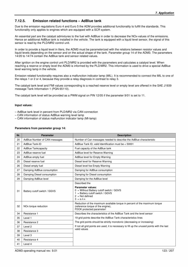
7. Application
ADM3 operating manual rev. 9.01 123 / 207
7.12.5. Emission related functions – AdBlue tank
Due to the emission regulations Euro 4 and Euro 5 the ADM provides additional functionality to fulfill the standards. This functionality only applies to engines which are equipped with a SCR system. An essential part are the catalyst admixtures to the fuel with AdBlue in order to decrease the NOx-values of the emissions. Hence an additional AdBlue tank is installed in the vehicle. The tank is equipped with a liquid level sensor, the signal of this sensor is read by the PLD/MR2 control unit. In order to provide a liquid level in liters, the ADM3 must be parameterized with the relations between resistor values and liquid levels depending on the sensor and on the actual shape of the tank. Parameter group 14 of the ADM3. The parameters 14/20 to 14/74 contain the AdBlue tank and sensor related values. After ignition on the engine control unit PLD/MR2 is provided with the parameters and calculates a catalyst level. When reaching a reserve or empty level the ADM3 is informed by the PLD/MR2. This information is used to drive a special AdBlue level warning lamp in the vehicle. Emission related functionality requires also a malfunction indicator lamp (MIL). It is recommended to connect the MIL to one of the relays 1 or 2 or 4, because they provide a relay diagnosis in contrast to relay 3. The catalyst tank level and FMI values corresponding to a reached reserve level or empty level are offered in the SAE J1939 message Tank Information 1 (PGN 65110). The catalyst tank level will be provided as a PWM signal on PIN 12/05 if the parameter 9/01 is set to 11. Input values: – AdBlue tank level in percent from PLD/MR2 via CAN connection – CAN information of status AdBlue warning level lamp – CAN information of status malfunction indicator lamp (MI-lamp) Parameters from parameter group 14:
Nr. Parameter Description
20 AdBlue Number of CAN messages Number of Can messages needed to describe the AdBlue characteristic
21 AdBlue Tank-ID AdBlue Tank ID, valid Identification must be < 50001
22 AdBlue Tankcapacity Fuel capacity of the AdBlue tank
23 AdBlue reserve fuel AdBlue level for Reserve Warning
24 AdBlue empty fuel AdBlue level for Empty Warning
25 Diesel reserve fuel Diesel level for Reserve Warning
26 Diesel empty fuel Diesel level foe Empty Warning
27 Damping AdBlue consumption Damping for AdBlue consumption
28 Damping Diesel consumption Damping for Diesel consumption
29 Damping AdBlue level Damping for the AdBlue level
31 Battery cutoff switch / GGVS
Described the
Parameter values: 0 = Without Battery cutoff switch / GGVS 1 = Battery cutoff switch / GGVS 2 = Not defined 3 = s.n.v.
32 NOx torque reduction Reduction of the maximum available torque in percent of the maximum torque (reference torque of the engine), FDOK protected parameter!
34 Resistance 1
35 Level 1
36 Resistance 2
37 Level 2
38 Resistance 3
39 Level 3
40 Resistance 4
41 Level 4
Describes the characteristics of the AdBlue Tank and the level sensor
19 grid points describe the AdBlue Tank characteristics lines
The grid points should be strictly monotonic (decreasing or increasing)
If not all grid points are used, it is necessary to fill up the unused points with the last valid values

7. Application
124 / 207 ADM3 operating manual rev. 9.01
Nr. Parameter Description
42 Resistance 5
43 Level 5
44 Resistance 6
45 Level 6
46 Resistance 7
47 Level 7
48 Resistance 8
49 Level 8
50 Resistance 9
51 Level 9
52 Resistance 10
53 Level 10
54 Resistance 11
55 Level 11
56 Resistance 12
57 Level 12
58 Resistance 13
59 Level 13
60 Resistance 14
61 Level 14
62 Resistance 15
63 Level 15
64 Resistance 16
65 Level 16
66 Resistance 17
67 Level 17
68 Resistance 18
69 Level 18
70 Resistance 19
71 Level 19
AdBlue Tank charactaristic
0
10
20
30
40
50
60
70
80
90
100
0 500 1000 1500 2000 2500 3000 3500 4000 4500 5000 5500 6000 6500 7000 7500
Resistance [Ohm]
Ad
Blu
e T
an
k f
uellevel [%
]
Example of an AdBlue characteristics line with all 19 grid points
72 Lower faulty Resistance A valid resistance value must be higher than this parameter
73 Upper faulty Resistance A valid resistance value must be lower than this parameter
74 Diesel Tank capacity Fuel capacity for the diesel tank
Output: - SAE J1939 CAN message Tank Information 1 with signals: catalyst tank level in percent and FMI to catalyst tank level warning status – Pin 15/12 REL1: AdBlue level warning lamp (parameter 16/01 set to 8) or MI-lamp (parameter 16/01 set to 7) – Pin 15/09 REL2: AdBlue level warning lamp (parameter 02/03 set to 7) or MI-lamp (parameter 02/03 set to 6) – Pin 15/11 REL3: AdBlue level warning lamp (parameter 14/01 set to 12) or MI-lamp (parameter 14/01 set to 11) – Pin 18/01 REL4: AdBlue level warning lamp (parameter 14/10 set to 13) or MI-lamp (parameter 14/10 set to 12) – Pin 12/05 IWA: AdBlue level with a range from 10 to 90% (parameter 09/01 set to 11)
19 grid points describe the characteristics line

7. Application
ADM3 operating manual rev. 9.01 125 / 207
7.12.6. Emission related functions – NOx torque reduction
In the Euro4/5 standards limits are defined for the NOx emissions of a vehicle. Due to the standard a signal is provided to the driver and later on a reduction of the maximum available torque of the engine. Be aware, that this functionaility only applies to engines which are equipped with a SCR system. The percentage of the torque reduction is defined in parameter 14/32, the parameter is FDOK protected and has a default value of 60%. The ADM3 is informed about the status of a torque limitation by the PLD/MR2 control unit. This information is used to drive a NOx lamp in the vehicle using one of the four output relays. The status information is also offered in the SAE J1939 CAN message Auxiliary Input/Output Status 1 (PGN 65241). The actual available torque of the engine as a percentage of the reference torque is considered in the SAE J1939 CAN message Engine Configuration 1. In the case of a torque limitation the speed/torque diagram is truncated to the parameterized value. Input values: – Status of NOx torque limitation from PLD/MR2 via CAN connection Parameter from parameter group 14:
Nr. Parameter Description
32 NOx torque reduction Reduction of the maximum available torque in percent of the maximum torque (reference torque of the engine), FDOK protected parameter!
Output: - SAE J1939 CAN message Auxiliary Input/Output Status 1, signal status NOx torque limitation (Byte 4, Bits 4,3) with the values: 0 = not active (NOx lamp off), 1 = active (NOx lamp on), 2 = active after next vehicle start (NOx lamp flashing) – Pin 15/12 REL1: NOx lamp (parameter 16/01 set to 9) – Pin 15/09 REL2: NOx lamp (parameter 02/03 set to 8) – Pin 15/11 REL3: NOx lamp (parameter 14/01 set to 13) – Pin 18/01 REL4: NOx lamp (parameter 14/10 set to 14)
7.12.7. TSC1 Speed Control and Speed Limitation
Depending on parameters in group 22 (TSC1 Limiter Governor (n max)) the speed governors for maximum engine speed limitation and engine speed control are selected. Limitation of maximum engine speed The governors for maximum engine speed limitation are chosen with the parameters 22/01 to 22/04, each of them dedicated to the source of the respective TSC1 message. 22/01 is responsible for the sender ABU (Antilock Braking System), 22/02 for TCU (Transmission), 22/03 for KWS (Third Source as defined in parameter 01/03), 22/04 for ACC (Adaptive Cruise Control). The governors for the maximum engine speed limitation are allocated to the ADM3 and the PLD/MR2 depending on the following settings of the parameters 22/01 to 22/04:
Nr. Parameter Description
01 Governor TSC1 Transmission Governor for torque speed control transmission limitation.
02 Governor TSC1 ABS Governor torque speed control ABS limitation.
03 Governor TSC1 Jack Knife Governor torque speed control Jack Knife limitation.
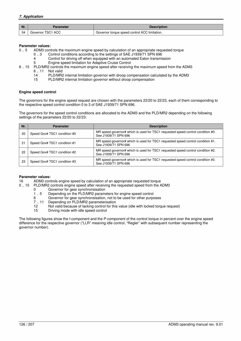
7. Application
126 / 207 ADM3 operating manual rev. 9.01
Nr. Parameter Description
04 Governor TSC1 ACC Governor torque speed control ACC limitation.
Parameter values: 0 .. 5 ADM3 controls the maximum engine speed by calculation of an appropriate requested torque
0 .. 3 Control conditions according to the settings of SAE J1939/71 SPN 696 4 Control for driving off when equipped with an automated Eaton transmission 5 Engine speed limitation for Adaptive Cruise Control
6 .. 15 PLD/MR2 controls the maximum engine speed after receiving the maximum speed from the ADM3 6 .. 11 Not valid 14 PLD/MR2 internal limitation governor with droop compensation calculated by the ADM3 15 PLD/MR2 internal limitation governor without droop compensation
Engine speed control The governors for the engine speed request are chosen with the parameters 22/20 to 22/23, each of them corresponding to the respective speed control condition 0 to 3 of SAE J1939/71 SPN 696. The governors for the speed control conditions are allocated to the ADM3 and the PLD/MR2 depending on the following settings of the parameters 22/20 to 22/23:
Nr. Parameter Description
20 Speed Gov# TSC1 condition #0 MR speed governor# which is used for TSC1 requested speed control condition #0. See J1939/71 SPN 696
21 Speed Gov# TSC1 condition #1 MR speed governor# which is used for TSC1 requested speed control condition #1. See J1939/71 SPN 696
22 Speed Gov# TSC1 condition #2 MR speed governor# which is used for TSC1 requested speed control condition #2. See J1939/71 SPN 696
23 Speed Gov# TSC1 condition #3 MR speed governor# which is used for TSC1 requested speed control condition #3. See J1939/71 SPN 696
Parameter values: 16 ADM3 controls engine speed by calculation of an appropriate requested torque 0 .. 15 PLD/MR2 controls engine speed after receiving the requested speed from the ADM3
0 Governor for gear synchronsisation 1 .. 5 Depending on the PLD/MR2 parameters for engine speed control 6 Governor for gear synchronsisation, not to be used for other purposes 7 .. 11 Depending on PLD/MR2 parameterisation 12 Not valid because of lacking control for this value (idle with locked torque request) 15 Driving mode with idle speed control
The following figures show the I-component and the P-component of the control torque in percent over the engine speed difference for the respective governor (“LLR” meaning idle control, “Regler” with subsequent number representing the governor number).

7. Application
ADM3 operating manual rev. 9.01 127 / 207
Fig. 22: I-component of control torque for engine speed control
Fig. 23: P-component of control torque for engine speed control
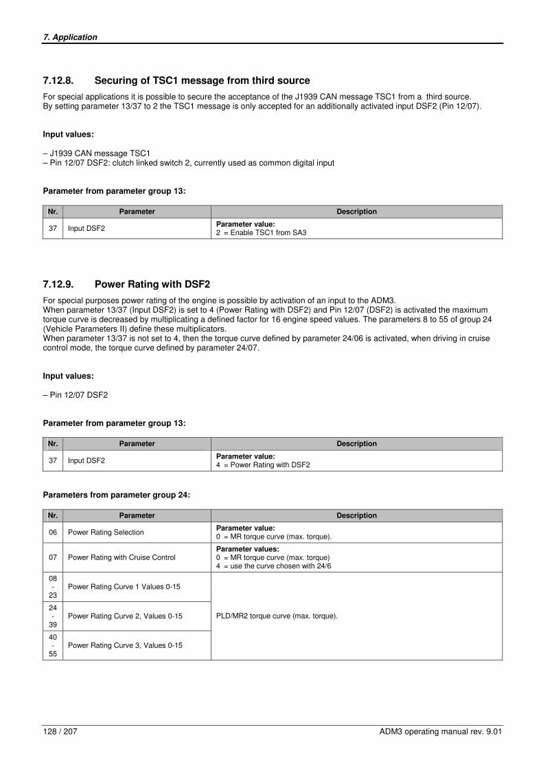
7. Application
128 / 207 ADM3 operating manual rev. 9.01
7.12.8. Securing of TSC1 message from third source
For special applications it is possible to secure the acceptance of the J1939 CAN message TSC1 from a third source. By setting parameter 13/37 to 2 the TSC1 message is only accepted for an additionally activated input DSF2 (Pin 12/07). Input values: – J1939 CAN message TSC1 – Pin 12/07 DSF2: clutch linked switch 2, currently used as common digital input Parameter from parameter group 13:
Nr. Parameter Description
37 Input DSF2 Parameter value: 2 = Enable TSC1 from SA3
7.12.9. Power Rating with DSF2
For special purposes power rating of the engine is possible by activation of an input to the ADM3. When parameter 13/37 (Input DSF2) is set to 4 (Power Rating with DSF2) and Pin 12/07 (DSF2) is activated the maximum torque curve is decreased by multiplicating a defined factor for 16 engine speed values. The parameters 8 to 55 of group 24 (Vehicle Parameters II) define these multiplicators. When parameter 13/37 is not set to 4, then the torque curve defined by parameter 24/06 is activated, when driving in cruise control mode, the torque curve defined by parameter 24/07. Input values: – Pin 12/07 DSF2 Parameter from parameter group 13:
Nr. Parameter Description
37 Input DSF2 Parameter value: 4 = Power Rating with DSF2
Parameters from parameter group 24:
Nr. Parameter Description
06 Power Rating Selection Parameter value: 0 = MR torque curve (max. torque).
07 Power Rating with Cruise Control Parameter values: 0 = MR torque curve (max. torque) 4 = use the curve chosen with 24/6
08 -
23 Power Rating Curve 1 Values 0-15
24 -
39 Power Rating Curve 2, Values 0-15
40 -
55 Power Rating Curve 3, Values 0-15
PLD/MR2 torque curve (max. torque).
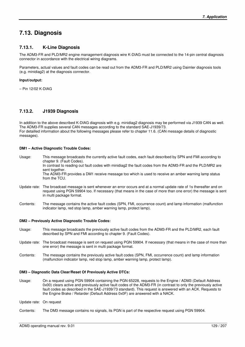
7. Application
ADM3 operating manual rev. 9.01 129 / 207
7.13. Diagnosis
7.13.1. K-Line Diagnosis
The ADM3-FR and PLD/MR2 engine management diagnosis wire K-DIAG must be connected to the 14-pin central diagnosis connector in accordance with the electrical wiring diagrams. Parameters, actual values and fault codes can be read out from the ADM3-FR and PLD/MR2 using Daimler diagnosis tools (e.g. minidiag2) at the diagnosis connector. Input/output: – Pin 12/02 K-DIAG
7.13.2. J1939 Diagnosis
In addition to the above described K-DIAG diagnosis with e.g. minidiag2 diagnosis may be performed via J1939 CAN as well. The ADM3-FR supplies several CAN messages according to the standard SAE-J1939/73. For detailled information about the following messages please refer to chapter 11.6. (CAN message details of diagnostic messages). DM1 – Active Diagnostic Trouble Codes: Usage: This message broadcasts the currently active fault codes, each fault described by SPN and FMI according to
chapter 9. (Fault Codes). In contrast to reading out fault codes with minidiag2 the fault codes from the ADM3-FR and the PLD/MR2 are sent together. The ADM3-FR provides a DM1 receive message too which is used to receive an amber warning lamp status from the TCU.
Update rate: The broadcast message is sent whenever an error occurs and at a normal update rate of 1s thereafter and on
request using PGN 59904 too. If necessary (that means in the case of more than one error) the message is sent in multi package format.
Contents: The message contains the active fault codes (SPN, FMI, occurrence count) and lamp information (malfunction
indicator lamp, red stop lamp, amber warning lamp, protect lamp). DM2 – Previously Active Diagnostic Trouble Codes: Usage: This message broadcasts the previously active fault codes from the ADM3-FR and the PLD/MR2, each fault
described by SPN and FMI according to chapter 9. (Fault Codes). Update rate: The broadcast message is sent on request using PGN 59904. If necessary (that means in the case of more than
one error) the message is sent in multi package format. Contents: The message contains the previously active fault codes (SPN, FMI, occurrence count) and lamp information
(malfunction indicator lamp, red stop lamp, amber warning lamp, protect lamp). DM3 – Diagnostic Data Clear/Reset Of Previously Active DTCs: Usage: On a request using PGN 59904 containing the PGN 65228, requests to the Engine / ADM3 (Default Address
0x00) clears active and previously active fault codes of the ADM3-FR (in contrast to only the previously active fault codes as described in the SAE-J1939/73 standard). This request is answered with an ACK. Requests to the Engine Brake / Retarder (Default Address 0x0F) are answered with a NACK.
Update rate: On request Contents: The DM3 message contains no signals, its PGN is part of the respective request using PGN 59904.

7. Application
130 / 207 ADM3 operating manual rev. 9.01
DM4 – Freeze Frame Parameters: Usage: This message broadcasts freeze frame data for up to 16 active or previously active fault codes. The DM4
message is a multi package message, each fault code derives in 13 Bytes length as part of the message. As for the messages DM1 and DM2 fault codes from the ADM3-FR and the PLD/MR2 are sent together.
Update rate: The message is sent on request using PGN 59904. Requests which are received within a 2s active J1939 bus
are answered with a NACK. Contents: The message contains the SPNs and FMIs and occurrence counts of the fault codes as for the DM1 and DM2
message and the freeze frame data which are Engine Torque Mode, Boost, Engine Speed, Engine Percent Load, Engine Coolant Temperature, Vehicle Speed.
DM11 – Diagnostic Clear/Reset For Active DTCs: Usage: On a request using PGN 59904 and containg the PGN 65235 for DM11, requests to the Engine / ADM3 and the
Engine Brake / Retarder are answered with a NACK causing no cleraing of fault codes. In order to clear fault codes please use the DM3 message.
Update rate: On request Contents: The DM11 message contains no signals, the PGN is part of the request message. DM13 – Stop Start Broadcast: Usage: The signals of this receive message cause a stop or start of broadcasting over the bus types J1939 and J1587.
On reception of a Stop Broadcast signal the ADM3-FR stops sending of its messages at the addressed bus. The current implementation does not make use of a sequence of receive messages to stop broadcasts as described in SAE-J1939/73, a suspend message is not sent by the ADM3-FR as well.
Update rate: The DM13 message has to be sent every 5s, after a timeout of 6s the ADM3-FR leaves the status of stopped
broadcast and begins to send messages again. Contents: The message contains Stop/Start signals for various bus types – J1939, J1587 and Current Data Link
(interpreted as J1939) are used by the ADM3-FR – and the Hold Signal.
7.13.3. Diagnosis of J1939 CAN messages and signals
The ADM3-FR is capable of performing diagnosis of J1939 messages and signals. By setting parameter 01/17 to 1, J1939 messages and signals are diagnosed depending on the current parameter set. In the case of active or previously active diagnostic trouble codes these can be read by Minidiag or the respective J1939 CAN messages DM1 and DM2. Three different failure causes have to be regarded: – a message containing the desired signal is missing,
this causes an ADM3 fault code with FMI 9 (Abnormal Update Rate) for the signal, – a signal is marked as not available,
this causes an ADM3 fault code with FMI 9 (Signal not Available), – a signal is marked erratic,
this causes an ADM3 fault code with FMI 19 (Received Network Data In Error). Following conditions have to be fulfilled to activate J1939 diagnosis: – sufficient battery voltage of 11.5V (for a nominal battery voltage of 12V) or 18V (for a nominal value of 24V) minimum, – ignition on for at least 1s, – J1939 bus active for at least 250ms, – no J1939 bus off, – engine running for at least 10s or engine speed equals zero, – parameter 01/17 set to 1. Input values: – J1939 CAN messages

7. Application
ADM3 operating manual rev. 9.01 131 / 207
Output values: – ADM3 fault codes (Minidiag or J1939 diagnostic messages DM1/DM2) Parameter from parameter group 1:
Nr. Parameter Description
17 J1939 Timeout Detection
Activation of diagnosis for J1939 CAN signals.
Signals are checked for “Not defined” (FMI 19) and “Signal Not Available” (FMI 09), missing messages lead to FMI 09 for signals that are used for the current parameter configuration
Parameter values: 0 = not active 1 = active
7.13.4. Malfunction Indicator Lamp
The malfunction indicator lamp, abbreviated with MIL, is used due to OBD regulations. The lamp can be connected to one of the 4 relays of the ADM3. However it is recommended to use relay 1 or 2 or 4, because these relays can be checked for errors (shorted or open circuit). The status of the MIL is received from the engine controller over the Low-Speed CAN. With this information the MIL is driven, when connected to one of the 4 relays. Additionally the MIL-status is sent back to the engine controller over the Low-Speed CAN and is transmitted on J1939-CAN. If the MI-lamp is connected to relay 1 or 2 or 4 and diagnosis of the respective relay, which drives the MIL shows an error, the MIL status will be transmitted back to the engine controller as “off” on the Low-Speed CAN and on the J1939-CAN in the messages DM1 and DM2. In the case the MI-Lamp is connected to relay 3 or it is parametered to none of the relays, then the MIL status is mirrored back on the Low-Speed CAN and transmitted unchanged on the J1939-CAN. Input values: – Low-Speed CAN message containing MIL status Output values: – Relays 1 to 4 – MIL status in J1939-CAN messages DM1 and DM2 – Low Speed CAN message Parameters:
- 02/03 Configuration Relay 2 / Grid heater parameter value = 6 (MI-Lamp)
- 14/01 Configuration Relay 3 (IWK3) parameter value = 11 (MI-Lamp)
- 14/10 Configuration Relay 4 (IWK4) parameter value = 12 (MI-Lamp)
- 16/01 Output Relay 1 /Starter Lockout parameter value = 7 (MI-Lamp)
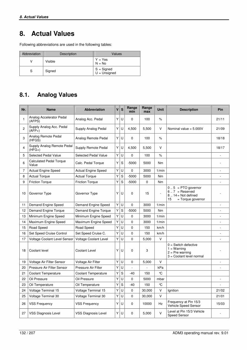
8. Actual Values
132 / 207 ADM3 operating manual rev. 9.01
8. Actual Values
Following abbreviations are used in the following tables:
Abbreviation Description Values
V Visible Y = Yes N = No
S Signed S = Signed U = Unsigned
8.1. Analog Values
Nr. Name Abbreviation V S Range
min Range max
Unit Description Pin
1 Analog Accelerator Pedal (AFPS)
Analog Acc. Pedal Y U 0 100 % 21/11
2 Supply Analog Acc. Pedal (AFP+)
Supply Analog Pedal Y U 4,500 5,500 V Nominal value = 5.000V 21/09
3 Analog Remote Pedal (HFGS)
Analog Remote Pedal Y U 0 100 % 18/18
4 Supply Analog Remote Pedal (HFG+)
Supply Remote Pedal Y U 4,500 5,500 V 18/17
5 Selected Pedal Value Selected Pedal Value Y U 0 100 % -
6 Calculated Pedal Torque Value
Calc. Pedal Torque Y S -5000 5000 Nm -
7 Actual Engine Speed Actual Engine Speed Y U 0 3000 1/min -
8 Actual Torque Actual Torque Y S -5000 5000 Nm -
9 Friction Torque Friction Torque Y S -5000 0 Nm -
10 Governor Type Governor Type Y U 0 15 -
0 .. 5 = PTO governor 6 .. 7 = Reserved 8 .. 14 = Not defined 15 = Torque governor
-
11 Demand Engine Speed Demand Engine Speed Y U 0 3000 1/min -
12 Demand Engine Torque Demand Engine Torque Y S -5000 5000 Nm -
13 Minimum Engine Speed Minimum Engine Speed Y U 0 3000 1/min -
14 Maximum Engine Speed Maximum Engine Speed Y U 0 3000 1/min -
15 Road Speed Road Speed Y U 0 150 km/h -
16 Set Speed Cruise Control Set Speed Cruise C. Y U 0 150 km/h -
17 Voltage Coolant Level Sensor Voltage Coolant Level Y U 0 5,000 V -
18 Coolant level Coolant Level Y U 0 3
0 = Switch defective 1 = Warning 2 = Pre warning 3 = Coolant level normal
-
19 Voltage Air Filter Sensor Voltage Air Filter Y U 0 5,000 V -
20 Pressure Air Filter Sensor Pressure Air Filter Y U - - kPa -
21 Coolant Temperature Coolant Temperature Y S -40 150 °C
22 Oil Pressure Oil Pressure Y U 0 5000 mbar -
23 Oil Temperature Oil Temperature Y S -40 150 °C -
24 Voltage Terminal 15 Voltage Terminal 15 Y U 0 30,000 V Ignition 21/02
25 Voltage Terminal 30 Voltage Terminal 30 Y U 0 30,000 V 21/01
26 VSS Frequency VSS Frequency Y U 0 10000 Hz Frequency at Pin 15/3 Vehicle Speed Sensor
15/03
27 VSS Diagnosis Level VSS Diagnosis Level Y U 0 5,000 V Level at Pin 15/3 Vehicle Speed Sensor
-

8. Actual Values
ADM3 operating manual rev. 9.01 133 / 207
Nr. Name Abbreviation V S Range
min Range max
Unit Description Pin
28 SAE J1939 Current Active TSC1 Sender
J1939 Active TSC1 Y U 0 255 - -
29 SAE J1939 Demand Engine Speed
J1939 dem. Speed Y U 0 3000 1/min -
30 SAE J1939 Demand Torque J1939 Dem. Torque Y S -125 125 % -
31 SAE J1939 Maximum Engine Speed
J1939 Max. Speed Y U 0 3000 1/min -
32 SAE J1939 Maximum Torque J1939 Max. Torque Y S -125 125 % -
33 PWM Pedal Signal GAS1 PWM Pedal GAS1 Y U 0 100 % Idle: 10% .. 30% o.k, Max. Load: 40%..90% o.k.
21/12
34 PWM Pedal Signal GAS2 PWM Pedal GAS2 Y U 0 100 % Idle: 10% .. 30% o.k. Max. Load: 40%..90% o.k.
21/13
35 Status Grid Heater Status Grid Heater Y U 0 6 -
0 = Disabled 1 = Preheating phase 2 = Ready for starting 3 = Starting 4 = Postheating phase 5 = Cooling off phase 6 = End
-
36 Boost Temperature Boost Temperature Y S -50 200 °C -
37 IWA output IWA output Y U 0 100 % 12/05
38 Software Version Software Version Y U - - - -
39 Actual Torque corrected Actual Torque corr. Y S -5000 5000 Nm -
40 Reference Torque Reference Torque Y U 0 5000 Nm J1939 Engine Configuration Reference Torque
-
41 Abs.max. Engine Torque Abs.max. Engine Torque Y U 0 5000 Nm -
42 EEC1, SA controlling device EEC1, SA contr. dev. Y U 0 255 - EEC1, Byte 6 -
43 ERC1, SA controlling device ERC1, SA cont. dev. Y U 0 255 - ERC1, Byte 5 -
44 Torque of Inertia J1939 Torque of Inertia Y U 0,00 10,00 kgm2
Engine Torque of Inertia J1939 Engine Conf. Map (PGN 65251)
-
45 Max.Retarder Torque Max.Retarder Torque Y U - - Nm Status-dependent maximum engine brake torque
-
46 ER Torque Curve ER Torque learned Y U - - - 0 = not learned 1 = learned (OK)
-
47 ECU-Hardware ECU-Hardware Y U - - - Hardware configuration / Connectors mounted on ECU
-
48 Power rating, requested engine map
requested engine map Y U 0 14 - -
49 Power rating, actual engine map
actual engine map Y U 0 14 - -
50 Fuel Filter Fuel Filter Y U - - kPa -
51 Nmax Gov0 rpm Nmax Gov0 rpm Y U - - rpm -
52 Nmax Gov1 rpm Nmax Gov1 rpm Y U - - rpm -
53 Nmax Gov2 rpm Nmax Gov2 rpm Y U - - rpm -
54 Nmax Gov3 rpm Nmax Gov3 rpm Y U - - rpm -
55 Nmax Gov4 rpm Nmax Gov4 rpm Y U - - rpm -
56 Transmission Input Speed Transm. Input Speed Y U - - rpm -
57 Transmission Input Sensor Frequency
Transm. Input S_Freq Y U - - Hz -
58 Engine Type Engine Type Y U - - BR -
59 Ambient Air Temperature Ambient Air Temp. Y S -273 1735 °C -

8. Actual Values
134 / 207 ADM3 operating manual rev. 9.01
8.2. Binary Values
Nr. Name Abbreviation Status 00/01 Description Pin
1/1 Terminal 15 Terminal 15 Off/On Ignition 21/02
1/2 Service Brake Service Brake Off/On - 21/15
1/3 Park Brake Park Brake Off/On - 21/16
1/4 Clutch Clutch Closed/ Open - 18/02
2/1 Cruise Control Switch CC- Cruise Control CC- Off/On On = Set and Decelerate 18/04
2/2 Cruise Control Switch CC+ Cruise Control CC+ Off/On On = Resume and accelerate 18/05
2/3 Cruise Control Switch CC_EIN Cruise Control CC_EIN Off/On On = Enable Cruise Control 18/06
2/4 Throttle Select Switch FG_WAHL Throttle Select Off/On Off = accelerator pedal On = remote pedal
18/07
3/1 Engine Brake Low MBR_L Engine Brake Low Off/On - 18/08
3/2 Engine Brake High MBR_H Engine Brake High Off/On - 18/09
3/3 PTO Control Set Switch PTO Set Switch Off/On 18/10
3/4 Limiter0 Set Switch Limiter0 Set Switch Off/On - 18/11
4/1 Limiter1 Set Switch Limiter1 Set Switch Off/On - 18/12
4/2 Shutdown Override MABSCH_SP Shutdown Override Off/On - 18/13
4/3 Limiter Klima Set Switch Limiter Klima Switch Off/On - 18/14
4/4 Fan Fan Off/On - 18/15
5/1 Acceleretor Pedal Lockout Acc. Pedal Lockout No/Yes On active input acc. pedal and remote pedal are disabled.
18/16
5/2 Transmission Neutral NE Transm. Neutral Off/On - 15/01
5/3 Rear Axle HA Rear Axle Off/On - 15/02
5/4 ABS ABS Off/On SAE J1939, preliminary -
6/1 GAS2 (analog throttle) GAS2 (IVS 1) Off/On Idle validation switch 1 of analog throttle
21/13
6/2 GAS1 (analog throttle) GAS1 (IVS 2) Off/On Idle validation switch 2 of analog throttle
21/12
6/3 engine brake(s) off eng. brake(s) v. J19 No/Yes shutdown via SAE J1939 -
6/4 Kickdown Kickdown No/Yes throttle pedal -
7/1 zero Injection zero injection No/Yes Engine stop demand on PLD/MR2 via engine-CAN, ref. Chapter 7 of manual
-
7/2 zero injection via J1939 zero injection J1939 No/Yes Engine stop demand via SAE J1939 with PGN 61184, ref. Chapter 7 and 11 of manual
-
7/3 starter signal (Kl. 50) starter signal (Kl. 50) Off/On starter signal (Ignition key) 12/01
7/4 DSF0 DSF0 Off/On configurable input DSF0 12/10
8/1 DSF1 DSF1 Off/On configurable input DSF1 12/09
8/2 MBR-BK MBR-BK Off/On Exhaust brake valve 15/06
8/3 MBR-KD MBR-KD Off/On Decompression valve 15/10
8/4 relay 1 relay 1 Off/On 15/12
9/1 relay 2 relay 2 Off/On 15/09
9/2 relay 3 relay 3 Off/On 15/11
9/3 relay 4 relay 4 Off/On 18/01
9/4 engine hood (bus) engine hood (bus) Off/On 12/08
10/1 CC Pause CC Pause Off/On only via J1939 CC or stalk switch
-
10/2 status road speed limiter stat. road speed lim Off/On -
10/3 reserved reserved 0/1 -
10/4 Transponder Transponder Off/On
11/1 reserved reserved - -
11/2 DSF2 Status DSF2 Status Off/On configurable input DSF2 12/07
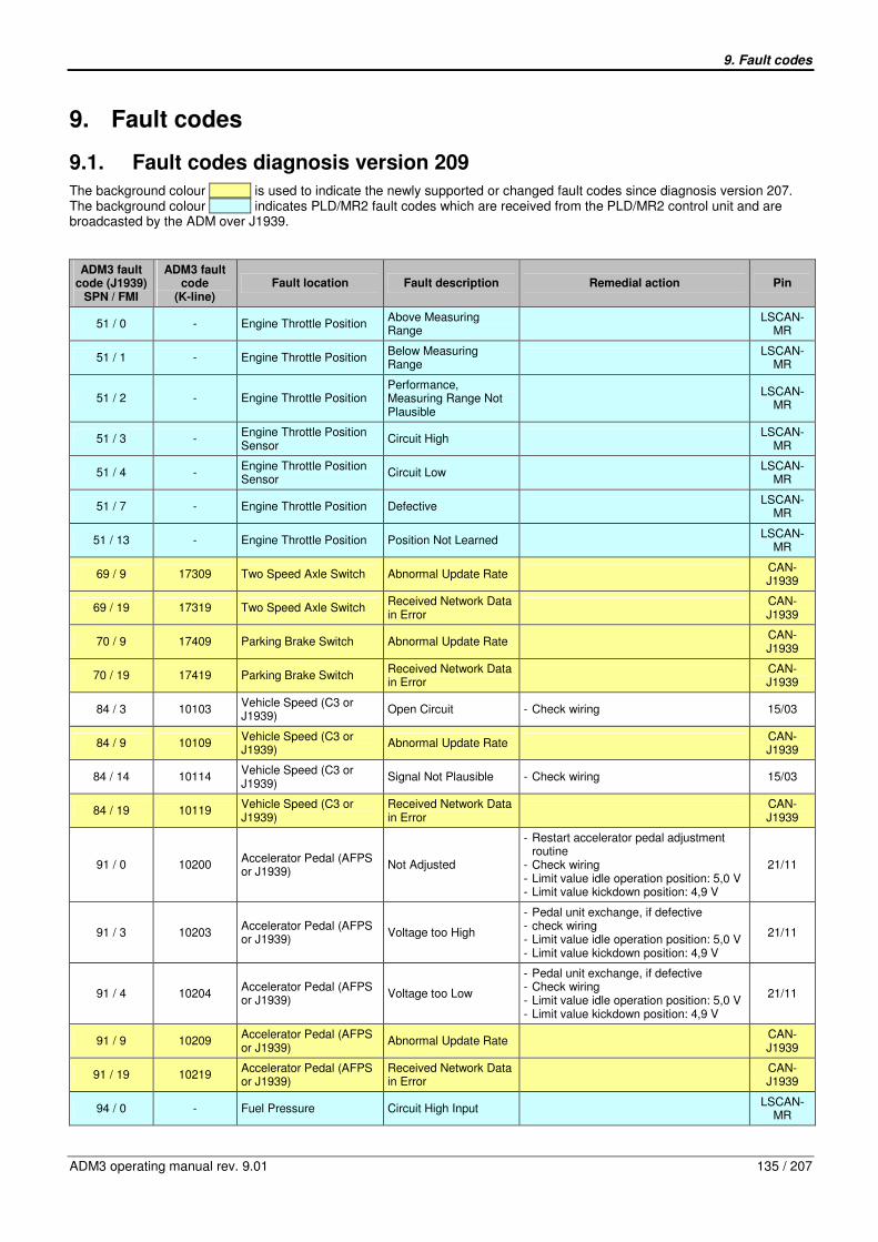
9. Fault codes
ADM3 operating manual rev. 9.01 135 / 207
9. Fault codes
9.1. Fault codes diagnosis version 209
The background colour is used to indicate the newly supported or changed fault codes since diagnosis version 207. The background colour indicates PLD/MR2 fault codes which are received from the PLD/MR2 control unit and are broadcasted by the ADM over J1939.
ADM3 fault code (J1939)
SPN / FMI
ADM3 fault code
(K-line) Fault location Fault description Remedial action Pin
51 / 0 - Engine Throttle Position Above Measuring Range
LSCAN-
MR
51 / 1 - Engine Throttle Position Below Measuring Range
LSCAN-
MR
51 / 2 - Engine Throttle Position Performance, Measuring Range Not Plausible
LSCAN-
MR
51 / 3 - Engine Throttle Position Sensor
Circuit High LSCAN-
MR
51 / 4 - Engine Throttle Position Sensor
Circuit Low LSCAN-
MR
51 / 7 - Engine Throttle Position Defective LSCAN-
MR
51 / 13 - Engine Throttle Position Position Not Learned LSCAN-
MR
69 / 9 17309 Two Speed Axle Switch Abnormal Update Rate CAN-J1939
69 / 19 17319 Two Speed Axle Switch Received Network Data in Error
CAN-J1939
70 / 9 17409 Parking Brake Switch Abnormal Update Rate CAN-J1939
70 / 19 17419 Parking Brake Switch Received Network Data in Error
CAN-J1939
84 / 3 10103 Vehicle Speed (C3 or J1939)
Open Circuit - Check wiring 15/03
84 / 9 10109 Vehicle Speed (C3 or J1939)
Abnormal Update Rate CAN-J1939
84 / 14 10114 Vehicle Speed (C3 or J1939)
Signal Not Plausible - Check wiring 15/03
84 / 19 10119 Vehicle Speed (C3 or J1939)
Received Network Data in Error
CAN-J1939
91 / 0 10200 Accelerator Pedal (AFPS or J1939)
Not Adjusted
- Restart accelerator pedal adjustment routine - Check wiring - Limit value idle operation position: 5,0 V - Limit value kickdown position: 4,9 V
21/11
91 / 3 10203 Accelerator Pedal (AFPS or J1939)
Voltage too High
- Pedal unit exchange, if defective - check wiring - Limit value idle operation position: 5,0 V - Limit value kickdown position: 4,9 V
21/11
91 / 4 10204 Accelerator Pedal (AFPS or J1939)
Voltage too Low
- Pedal unit exchange, if defective - Check wiring - Limit value idle operation position: 5,0 V - Limit value kickdown position: 4,9 V
21/11
91 / 9 10209 Accelerator Pedal (AFPS or J1939)
Abnormal Update Rate CAN-J1939
91 / 19 10219 Accelerator Pedal (AFPS or J1939)
Received Network Data in Error
CAN-J1939
94 / 0 - Fuel Pressure Circuit High Input LSCAN-
MR
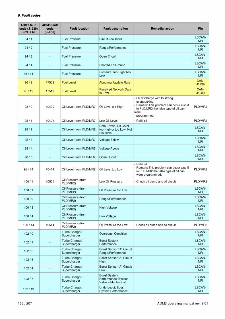
9. Fault codes
136 / 207 ADM3 operating manual rev. 9.01
ADM3 fault code (J1939)
SPN / FMI
ADM3 fault code
(K-line) Fault location Fault description Remedial action Pin
94 / 1 - Fuel Pressure Circuit Low Input LSCAN-
MR
94 / 2 - Fuel Pressure Range/Performance LSCAN-
MR
94 / 3 - Fuel Pressure Open Circuit LSCAN-
MR
94 / 4 - Fuel Pressure Shorted To Ground LSCAN-
MR
94 / 14 - Fuel Pressure Pressure Too High/Too Low
LSCAN-
MR
96 / 9 17509 Fuel Level Abnormal Update Rate CAN-J1939
96 / 19 17519 Fuel Level Received Network Data in Error
CAN-J1939
98 / 0 10400 Oil Level (from PLD/MR2) Oil Level too High
- Oil discharge with to strong overstocking. - Remark: This problem can occur also if in PLD/MR2 the false type of oil pan were programmed.
PLD/MR2
98 / 1 10401 Oil Level (from PLD/MR2) Low Oil Level - Refill oil PLD/MR2
98 / 2 - Oil Level (from PLD/MR2) Data Erratic, Oil Level too High or too Low, Not Plausible
LSCAN-
MR
98 / 3 - Oil Level (from PLD/MR2) Voltage Below LSCAN-
MR
98 / 4 - Oil Level (from PLD/MR2) Voltage Above LSCAN-
MR
98 / 5 - Oil Level (from PLD/MR2) Open Circuit LSCAN-
MR
98 / 14 10414 Oil Level (from PLD/MR2) Oil Level too Low
- Refill oil - Remark: This problem can occur also if in PLD/MR2 the false type of oil pan were programmed.
PLD/MR2
100 / 1 10501 Oil Pressure (from PLD/MR2)
Low Oil Pressure - Check oil pump and oil circuit PLD/MR2
100 / 1 - Oil Pressure (from PLD/MR2)
Oil Pressure too Low LSCAN-
MR
100 / 2 - Oil Pressure (from PLD/MR2)
Range/Performance LSCAN-
MR
100 / 3 - Oil Pressure (from PLD/MR2)
High Voltage LSCAN-
MR
100 / 4 - Oil Pressure (from PLD/MR2)
Low Voltage LSCAN-
MR
100 / 14 10514 Oil Pressure (from PLD/MR2)
Oil Pressure too Low - Check oil pump and oil circuit. PLD/MR2
102 / 0 - Turbo Charger/ Supercharger
Overboost Condition LSCAN-
MR
102 / 1 - Turbo Charger/ Supercharger
Boost System Performance
LSCAN-
MR
102 / 2 - Turbo Charger/ Supercharger
Boost Sensor “A” Circuit Range/Performance
LSCAN-
MR
102 / 3 - Turbo Charger/ Supercharger
Boost Sensor “A” Circuit High
LSCAN-
MR
102 / 4 - Turbo Charger/ Supercharger
Boost Sensor “A” Circuit Low
LSCAN-
MR
102 / 7 - Turbo Charger/ Supercharger
Boost System Performance, Bypass Valve – Mechanical
LSCAN-
MR
102 / 13 - Turbo Charger/ Supercharger
Underboost, Boost System Performance
LSCAN-
MR

9. Fault codes
ADM3 operating manual rev. 9.01 137 / 207
ADM3 fault code (J1939)
SPN / FMI
ADM3 fault code
(K-line) Fault location Fault description Remedial action Pin
103 / 3 - Turbo Charger Speed Sensor
Circuit Low LSCAN-
MR
103 / 4 - Turbo Charger Speed Sensor
Circuit High LSCAN-
MR
103 / 7 - Turbo Charger Speed Sensor
Signal Timeout, no revolution on charger 1
LSCAN-
MR
103 / 14 - Generator Speed Sensing Signal Timeout, no revolution on charger 2
LSCAN-
MR
105 / 0 - Intake Air Temperature Temperature Too high LSCAN-
MR
105 / 3 - Intake Air Temperature Sensor 1
Circuit High LSCAN-
MR
105 / 4 - Intake Air Temperature Sensor 1
Circuit Low LSCAN-
MR
107 / 0 10800 Air Filter Sensor (LF_SE) Differential Pressure too High
- Check wiring. 15/08
107 / 3 10803 Air Filter Sensor (LF_SE) Open Circuit - Check wiring. 15/08
107 / 4 10804 Air Filter Sensor (LF_SE) Short Circuit to Ground - Check wiring. 15/08
110 / 0 - Coolant Temperature (from PLD/MR2)
High Coolant Temperature
- Cooling-water level and cooling circuit check.
LSCAN-MR
110 / 3 - Coolant Temperature (from PLD/MR2)
Sensor 1 Circuit High LSCAN-
MR
110 / 4 - Coolant Temperature (from PLD/MR2)
Sensor 1 Circuit Low LSCAN-
MR
110 / 14 10914 Coolant Temperature (from PLD/MR2)
Coolant Temperature too High
- Cooling-water level and cooling circuit check.
PLD/MR2
111 / 1 11001 Coolant Level Sensor (KW_SE)
Low Coolant Level - Refill coolant - Check wiring
15/07
111 / 3 11003 Coolant Level Sensor (KW_SE)
Open Circuit - Check wiring - Voltage must be larger than 2,0 V.
15/07
111 / 4 11004 Coolant Level Sensor (KW_SE)
Short Circuit to Ground - Check wiring. 15/07
111 / 14 11014 Coolant Level Sensor (KW_SE)
Coolant Level too Low - Refill coolant - Check wiring
15/07
158 / 0 11100 Battery Voltage Switched (Terminal 15)
Over Voltage - Check battery voltage - Check parameter 2/08 (24V/12V selection)
21/02
158 / 1 11101 Battery Voltage Switched (Terminal 15)
Under Voltage - Check battery voltage - Check parameter 2/08 (24V/12V selection)
21/02
158 / 2 - Battery Voltage Switched (Terminal 15)
Inconsistent LSCAN-
MR
158 / 14 - Battery Voltage Switched (Terminal 15)
Starter Switch Inconsistent
LSCAN-
MR
161 / 9 17609 Transmission Input Shaft Speed
Abnormal Update Rate CAN-J1939
161 / 19 17619 Transmission Input Shaft Speed
Received Network Data in Error
CAN-J1939
168 / 3 - System Voltage Voltage High LSCAN-
MR
168 / 4 - System Voltage Voltage Low LSCAN-
MR
171 / 2 - Ambient Air Temperature Sensor Circuit Range/Performance
LSCAN-
MR
171 / 9 - Ambient Air Temperature Lost Message LSCAN-
MR
171 / 9 16609 Ambient Air Temperature Abnormal Update Rate CAN-J1939
171 / 19 16619 Ambient Air Temperature Received Network Data in Error
CAN-J1939

9. Fault codes
138 / 207 ADM3 operating manual rev. 9.01
ADM3 fault code (J1939)
SPN / FMI
ADM3 fault code
(K-line) Fault location Fault description Remedial action Pin
173 / 0 - Engine Exhaust Gas Temperature
Above Nominal Value LSCAN-
MR
173 / 15 - Engine Exhaust Gas Temperature
Too High LSCAN-
MR
174 / 3 - Fuel Temperature Sensor “A”
Circuit High Input LSCAN-
MR
174 / 4 - Fuel Temperature Sensor “A”
Circuit Low Input LSCAN-
MR
175 / 3 - Engine Oil Temperature Sensor
Circuit High LSCAN-
MR
175 / 4 - Engine Oil Temperature Sensor
Ciruit Low LSCAN-
MR
190 / 0 - Engine Speed Engine Overspeed Condition
LSCAN-
MR
191 / 9 17709 Transmission Output Shaft Speed
Abnormal Update Rate CAN-J1939
191 / 19 17719 Transmission Output Shaft Speed
Received Network Data in Error
CAN-J1939
354 / 3 - Ambient Air Combi Sensor, Part Humidity
Circuit High LSCAN-
MR
354 / 4 - Ambient Air Combi Sensor, Part Humidity
Circuit Low LSCAN-
MR
523 / 9 17809 Transmission Current Gear
Abnormal Update Rate CAN-J1939
523 / 19 17819 Transmission Current Gear
Received Network Data in Error
CAN-J1939
524 / 9 17909 Transmission Selected Gear
Abnormal Update Rate CAN-J1939
524 / 19 17919 Transmission Selected Gear
Received Network Data in Error
CAN-J1939
558 / 1 11701 Accelerator Pedal Idle Switch (GAS1 + GAS2 or J1939)
Both Signals Equal but Should Not
- Check wiring 21/12 and
21/13
558 / 5 11705 Accelerator Pedal Idle Switch (GAS1 + GAS2 or J1939)
Both Switches Open Circuit
- Check wiring - Pedal unit exchange, if defective
21/12 and 21/13
558 / 9 11709 Accelerator Pedal Idle Switch (GAS1 + GAS2 or J1939)
Abnormal Update Rate CAN-J1939
558 / 12 11712 Accelerator Pedal Idle Switch (GAS1 + GAS2 or J1939)
Both Switches Closed - check wiring - Pedal unit exchange, if defective
21/12 and 21/13
558 / 19 11719 Accelerator Pedal Idle Switch (GAS1 + GAS2 or J1939)
Received Network Data in Error
CAN-J1939
559 / 9 18009 Accelerator Pedal Kickdown Switch
Abnormal Update Rate CAN-J1939
559 / 19 18019 Accelerator Pedal Kickdown Switch
Received Network Data in Error
CAN-J1939
573 / 9 18109 Transmission Torque Converter Lockup Engaged
Abnormal Update Rate CAN-J1939
573 / 19 18119 Transmission Torque Converter Lockup Engaged
Received Network Data in Error
CAN-J1939
574 / 9 18209 Transmission Shift In Process
Abnormal Update Rate CAN-J1939
574 / 19 18219 Transmission Shift In Process
Received Network Data in Error
CAN-J1939
596 / 9 18309 Cruise Control Enable Switch
Abnormal Update Rate CAN-J1939

9. Fault codes
ADM3 operating manual rev. 9.01 139 / 207
ADM3 fault code (J1939)
SPN / FMI
ADM3 fault code
(K-line) Fault location Fault description Remedial action Pin
596 / 19 18319 Cruise Control Enable Switch
Received Network Data in Error
CAN-J1939
597 / 9 18409 Brake Switch Abnormal Update Rate CAN-J1939
597 / 19 18419 Brake Switch Received Network Data in Error
CAN-J1939
598 / 9 18509 Clutch Switch Abnormal Update Rate CAN-J1939
598 / 19 18519 Clutch Switch Received Network Data in Error
CAN-J1939
599 / 9 11809 Cruise Control Switch CC- (Set + Coast)
Abnormal Update Rate (Set Switch)
CAN-J1939
599 / 12 11812 Cruise Control Switch CC- (Set + Coast)
Both Switches CC- and CC+ Closed
- Check wiring - Check cruise control switch
18/04 and 18/05
599 / 14 11814 Cruise Control Switch CC- (Set + Coast)
Plausibility Check Failed (Check Stalk Switch Wiring)
- Check wiring of stalk switch - Check parameter 13/37
18/04 and 12/07
599 / 19 11819 Cruise Control Switch CC- (Set + Coast)
Received Network Data in Error
CAN-J1939
600 / 9 18609 Cruise Control Coast (Decelerate) Switch
Abnormal Update Rate CAN-J1939
600 / 19 18619 Cruise Control Coast (Decelerate) Switch
Received Network Data in Error
CAN-J1939
601 / 9 11909 Cruise Control Switch CC+ (Res + Acc)
Abnormal Update Rate (Resume Switch)
CAN-J1939
601 / 12 11912 Cruise Control Switch CC+ (Res + Acc)
Both Switches CC+ and CC- Closed
- Check wiring - Check cruise control switch
18/04 and 18/05
601 / 14 11914 Cruise Control Switch CC+ (Res + Acc)
Plausibility Check Failed (Check Stalk Switch Wiring)
- Check wiring of stalk switch - Check parameter 13/37
18/05 and 12/07
601 / 19 11919 Cruise Control Switch CC+ (Res + Acc)
Received Network Data in Error
CAN-J1939
602 / 9 18709 CCVS Cruise Control Accelerate Switch
Abnormal Update Rate or Signal Not Available
CAN-J1939
602 / 19 18719 CCVS Cruise Control Accelerate Switch
Received Network Data in Error
CAN-J1939
609 / 0 - Anti Theft Device Immobilizer Number of Keys Limited to 8
LSCAN-
MR
609 / 2 12002 PLD/MR2 Error Unknown Cause - Check PLD/MR2 Error Codes PLD/MR2
609 / 9 - Anti Theft Device Immobilizer TPC Signal Error Starter Line
LSCAN-
MR
609 / 11 - PLD/MR2, Anti Theft Device
Data Map Manipulated, Immobilizer Automatically Activated
LSCAN-
MR
609 / 12 - PLD/MR2, Barometric Pressure Circuit, Controller #2
PLD/MR2 Bad Device, Pressure Sensor Open Circuit or Shorted to Ground, Auxiliary Voltage 8,5V Defective, Common Internal Error, Boot Load Data, Boot Block Defective, Flash Memory Defective, , No Application Software In Flash Application Software Defective, Flash Not Erasable
LSCAN-
MR
609 / 13 - PLD/MR2 No. Of Cylinders Not Corresponding To Engine Type
LSCAN-
MR
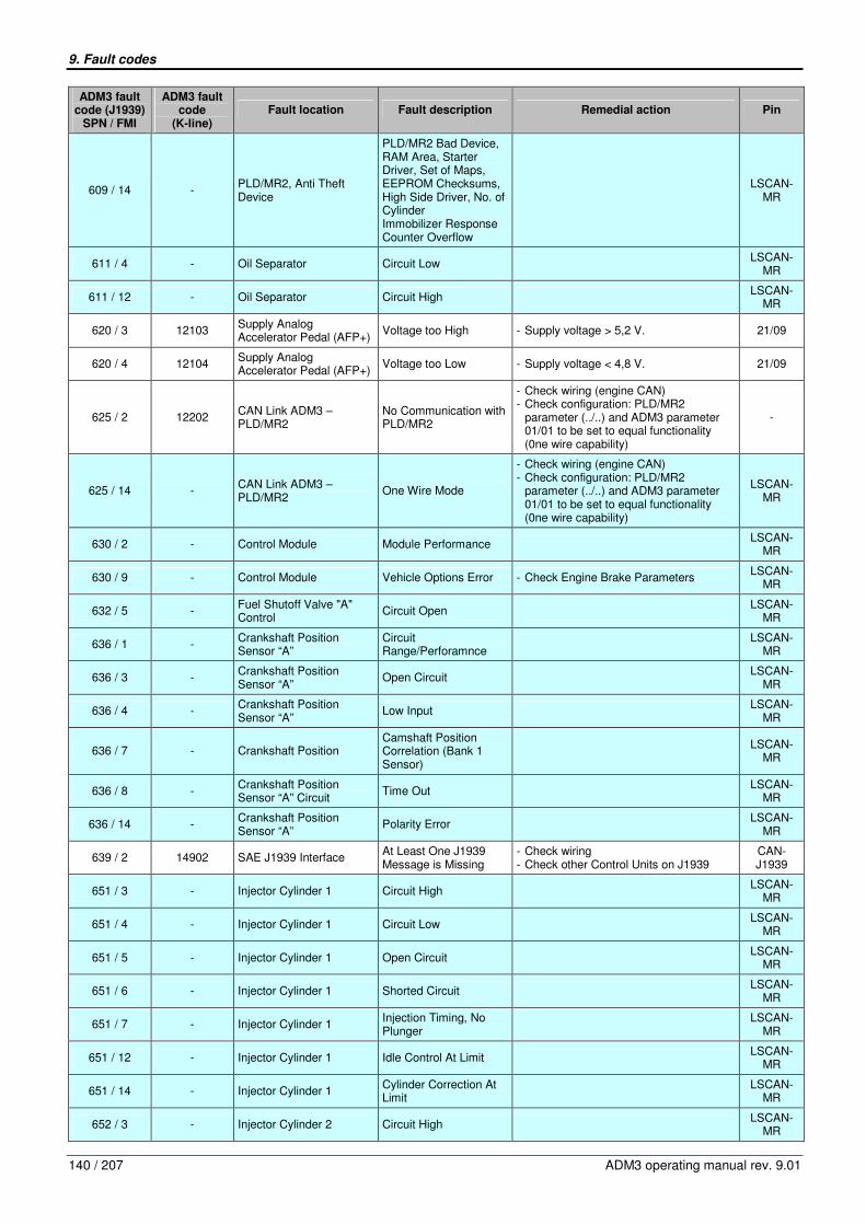
9. Fault codes
140 / 207 ADM3 operating manual rev. 9.01
ADM3 fault code (J1939)
SPN / FMI
ADM3 fault code
(K-line) Fault location Fault description Remedial action Pin
609 / 14 - PLD/MR2, Anti Theft Device
PLD/MR2 Bad Device, RAM Area, Starter Driver, Set of Maps, EEPROM Checksums, High Side Driver, No. of Cylinder Immobilizer Response Counter Overflow
LSCAN-
MR
611 / 4 - Oil Separator Circuit Low LSCAN-
MR
611 / 12 - Oil Separator Circuit High LSCAN-
MR
620 / 3 12103 Supply Analog Accelerator Pedal (AFP+)
Voltage too High - Supply voltage > 5,2 V. 21/09
620 / 4 12104 Supply Analog Accelerator Pedal (AFP+)
Voltage too Low - Supply voltage < 4,8 V. 21/09
625 / 2 12202 CAN Link ADM3 – PLD/MR2
No Communication with PLD/MR2
- Check wiring (engine CAN) - Check configuration: PLD/MR2 parameter (../..) and ADM3 parameter 01/01 to be set to equal functionality (0ne wire capability)
-
625 / 14 - CAN Link ADM3 – PLD/MR2
One Wire Mode
- Check wiring (engine CAN) - Check configuration: PLD/MR2 parameter (../..) and ADM3 parameter 01/01 to be set to equal functionality (0ne wire capability)
LSCAN-MR
630 / 2 - Control Module Module Performance LSCAN-
MR
630 / 9 - Control Module Vehicle Options Error - Check Engine Brake Parameters LSCAN-
MR
632 / 5 - Fuel Shutoff Valve "A" Control
Circuit Open LSCAN-
MR
636 / 1 - Crankshaft Position Sensor “A”
Circuit Range/Perforamnce
LSCAN-
MR
636 / 3 - Crankshaft Position Sensor “A”
Open Circuit LSCAN-
MR
636 / 4 - Crankshaft Position Sensor “A”
Low Input LSCAN-
MR
636 / 7 - Crankshaft Position Camshaft Position Correlation (Bank 1 Sensor)
LSCAN-
MR
636 / 8 - Crankshaft Position Sensor “A” Circuit
Time Out LSCAN-
MR
636 / 14 - Crankshaft Position Sensor “A”
Polarity Error LSCAN-
MR
639 / 2 14902 SAE J1939 Interface At Least One J1939 Message is Missing
- Check wiring - Check other Control Units on J1939
CAN-J1939
651 / 3 - Injector Cylinder 1 Circuit High LSCAN-
MR
651 / 4 - Injector Cylinder 1 Circuit Low LSCAN-
MR
651 / 5 - Injector Cylinder 1 Open Circuit LSCAN-
MR
651 / 6 - Injector Cylinder 1 Shorted Circuit LSCAN-
MR
651 / 7 - Injector Cylinder 1 Injection Timing, No Plunger
LSCAN-
MR
651 / 12 - Injector Cylinder 1 Idle Control At Limit LSCAN-
MR
651 / 14 - Injector Cylinder 1 Cylinder Correction At Limit
LSCAN-
MR
652 / 3 - Injector Cylinder 2 Circuit High LSCAN-
MR
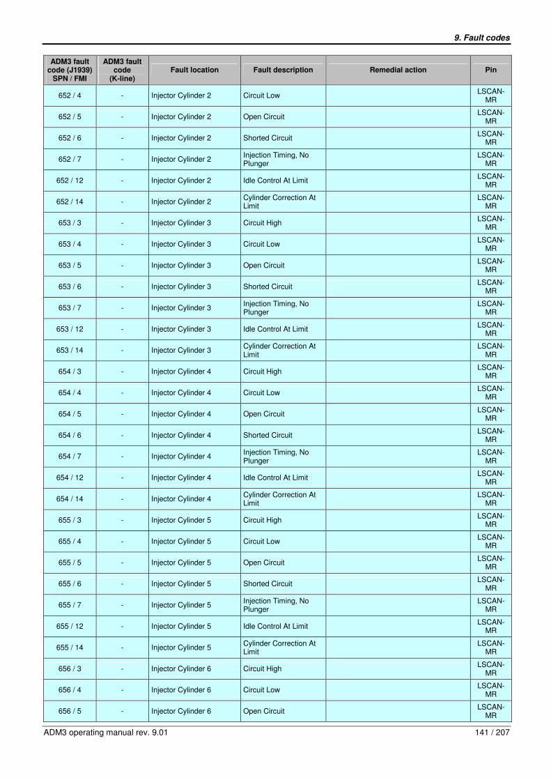
9. Fault codes
ADM3 operating manual rev. 9.01 141 / 207
ADM3 fault code (J1939)
SPN / FMI
ADM3 fault code
(K-line) Fault location Fault description Remedial action Pin
652 / 4 - Injector Cylinder 2 Circuit Low LSCAN-
MR
652 / 5 - Injector Cylinder 2 Open Circuit LSCAN-
MR
652 / 6 - Injector Cylinder 2 Shorted Circuit LSCAN-
MR
652 / 7 - Injector Cylinder 2 Injection Timing, No Plunger
LSCAN-
MR
652 / 12 - Injector Cylinder 2 Idle Control At Limit LSCAN-
MR
652 / 14 - Injector Cylinder 2 Cylinder Correction At Limit
LSCAN-
MR
653 / 3 - Injector Cylinder 3 Circuit High LSCAN-
MR
653 / 4 - Injector Cylinder 3 Circuit Low LSCAN-
MR
653 / 5 - Injector Cylinder 3 Open Circuit LSCAN-
MR
653 / 6 - Injector Cylinder 3 Shorted Circuit LSCAN-
MR
653 / 7 - Injector Cylinder 3 Injection Timing, No Plunger
LSCAN-
MR
653 / 12 - Injector Cylinder 3 Idle Control At Limit LSCAN-
MR
653 / 14 - Injector Cylinder 3 Cylinder Correction At Limit
LSCAN-
MR
654 / 3 - Injector Cylinder 4 Circuit High LSCAN-
MR
654 / 4 - Injector Cylinder 4 Circuit Low LSCAN-
MR
654 / 5 - Injector Cylinder 4 Open Circuit LSCAN-
MR
654 / 6 - Injector Cylinder 4 Shorted Circuit LSCAN-
MR
654 / 7 - Injector Cylinder 4 Injection Timing, No Plunger
LSCAN-
MR
654 / 12 - Injector Cylinder 4 Idle Control At Limit LSCAN-
MR
654 / 14 - Injector Cylinder 4 Cylinder Correction At Limit
LSCAN-
MR
655 / 3 - Injector Cylinder 5 Circuit High LSCAN-
MR
655 / 4 - Injector Cylinder 5 Circuit Low LSCAN-
MR
655 / 5 - Injector Cylinder 5 Open Circuit LSCAN-
MR
655 / 6 - Injector Cylinder 5 Shorted Circuit LSCAN-
MR
655 / 7 - Injector Cylinder 5 Injection Timing, No Plunger
LSCAN-
MR
655 / 12 - Injector Cylinder 5 Idle Control At Limit LSCAN-
MR
655 / 14 - Injector Cylinder 5 Cylinder Correction At Limit
LSCAN-
MR
656 / 3 - Injector Cylinder 6 Circuit High LSCAN-
MR
656 / 4 - Injector Cylinder 6 Circuit Low LSCAN-
MR
656 / 5 - Injector Cylinder 6 Open Circuit LSCAN-
MR

9. Fault codes
142 / 207 ADM3 operating manual rev. 9.01
ADM3 fault code (J1939)
SPN / FMI
ADM3 fault code
(K-line) Fault location Fault description Remedial action Pin
656 / 6 - Injector Cylinder 6 Shorted Circuit LSCAN-
MR
656 / 7 - Injector Cylinder 6 Injection Timing, No Plunger
LSCAN-
MR
656 / 12 - Injector Cylinder 6 Idle Control At Limit LSCAN-
MR
656 / 14 - Injector Cylinder 6 Cylinder Correction At Limit
LSCAN-
MR
657 / 5 - Injector Cylinder 7 Open Circuit LSCAN-
MR
657 / 6 - Injector Cylinder 7 Shorted Circuit LSCAN-
MR
657 / 7 - Injector Cylinder 7 Injection Timing, No Plunger
LSCAN-
MR
657 / 12 - Injector Cylinder 7 Idle Control At Limit LSCAN-
MR
657 / 14 - Injector Cylinder 7 Cylinder Correction At Limit
LSCAN-
MR
658 / 5 - Injector Cylinder 8 Open Circuit LSCAN-
MR
658 / 6 - Injector Cylinder 8 Shorted Circuit LSCAN-
MR
658 / 7 - Injector Cylinder 8 Injection Timing, No Plunger
LSCAN-
MR
658 / 12 - Injector Cylinder 8 Idle Control At Limit LSCAN-
MR
658 / 14 - Injector Cylinder 8 Cylinder Correction At Limit
LSCAN-
MR
677 / 3 - Output Relay 1 (PLD/MR2)
Shorted To High LSCAN-
MR
677 / 3 13303 Output Relay 1 (REL 1) Open Circuit - Check wiring - Check relay 1
15/12
677 / 4 13304 Output Relay 1 (REL 1) Short Circuit to Ground - Check wiring - Check relay 1
15/12
677 / 7 - Output Relay 1 (PLD/MR2)
Starter Stick, Does not Engage
LSCAN-
MR
677 / 14 - Output Relay 1 (PLD/MR2)
Starter Relay Stick LSCAN-
MR
697 / 3 - Proportional Valve 1 Circuit High, Shorted To Battery Voltage Bank 1
LSCAN-
MR
697 / 4 - Proportional Valve 1 Shorted To Ground Bank 1
LSCAN-
MR
697 / 5 - Proportional Valve 1 Open Circuit LSCAN-
MR
697 / 6 - Proportional Valve 1 Shorted To Ground LSCAN-
MR
698 / 3 - Proportional Valve 2 Shorted To Battery Voltage
LSCAN-
MR
698 / 5 - Proportional Valve 2 Open Circuit LSCAN-
MR
698 / 6 - Proportional Valve 2 Shorted To Ground LSCAN-
MR
699 / 3 - Proportional Valve 3 Shorted To Battery Voltage
LSCAN-
MR
699 / 5 - Proportional Valve 3 Open Circuit LSCAN-
MR
699 / 6 - Proportional Valve 3 Shorted To Ground LSCAN-
MR
700 / 3 - Proportional Valve 4 Shorted To Battery Voltage
LSCAN-
MR

9. Fault codes
ADM3 operating manual rev. 9.01 143 / 207
ADM3 fault code (J1939)
SPN / FMI
ADM3 fault code
(K-line) Fault location Fault description Remedial action Pin
700 / 5 - Proportional Valve 4 Open Circuit LSCAN-
MR
700 / 6 - Proportional Valve 4 Shorted To Ground LSCAN-
MR
705 / 3 - Proportional Valve 5 Shorted To Battery Voltage, Shorted To UB Bank 2
LSCAN-
MR
705 / 4 - Proportional Valve 5 Shorted To Ground, Shorted To Ground Bank 2
LSCAN-
MR
706 / 3 - Proportional Valve 6 Open Circuit LSCAN-
MR
706 / 5 - Proportional Valve 6 Shorted To Battery Voltage
LSCAN-
MR
706 / 6 - Proportional Valve 6 Shorted To Ground LSCAN-
MR
723 / 3 - Camshaft Position Sensor “A” (Bank 1 or Single Sensor)
Open Circuit LSCAN-
MR
723 / 4 - Camshaft Position Sensor “A” (Bank 1 or Single Sensor)
Shorted To Ground LSCAN-
MR
723 / 8 - Camshaft Position Sensor “A” (Bank 1 or Single Sensor)
Time Out LSCAN-
MR
723 / 14 - Camshaft Position Sensor “A” (Bank 1 or Single Sensor)
Polarity Error, Pins Swapped
LSCAN-
MR
729 / 3 14003 Intake Air Heater (MBR_KD)
Open Circuit - Check wiring - Check solenoid valve
15/10
729 / 4 14004 Intake Air Heater (MBR_KD)
Short Circuit to Ground - Check wiring - Check solenoid valve
15/10
729 / 5 - Intake Air Heater (PLD/MR2)
Circuit Open LSCAN-
MR
729 / 12 - Intake Air Heater (PLD/MR2)
Circuit Universal Troubles
LSCAN-
MR
730 / 0 13900 Output Relay 2 (REL 2)
Grid Heater: No Increasing Boost Temperature After Activation
- Check wiring - Check relay 2 - Check grid heater
15/09
730 / 1 13901 Output Relay 2 (REL 2) Grid Heater: Relay Permanently Closed
- Check wiring - Check relay 2
15/09
730 / 2 13902 Output Relay 2 (REL 2) Grid Heater: Relay Permanently Open
- Check wiring - Check relay 2
15/09
730 / 3 13903 Output Relay 2 (REL 2) Voltage too High when Activated
- Check wiring 15/09
730 / 4 13904 Output Relay 2 (REL 2) Voltage too Low when Activated
- Check wiring - Check relay 2
15/09
870 / 3 - SCR Diffusor Heating, Heater Regeneration System
Circuit High LSCAN-
MR
870 / 4 - SCR Diffusor Heating, Heater Regeneration System
Circuit Low LSCAN-
MR
870 / 5 - SCR Diffusor Heating Circuit Open LSCAN-
MR
904 / 9 18809 Front Axle Speed Abnormal Update Rate CAN-J1939
904 / 19 18819 Front Axle Speed Received Network Data in Error
CAN-J1939
925 / 3 - SCR Module Proportional Valve Bank
Circuit High LSCAN-
MR

9. Fault codes
144 / 207 ADM3 operating manual rev. 9.01
ADM3 fault code (J1939)
SPN / FMI
ADM3 fault code
(K-line) Fault location Fault description Remedial action Pin
925 / 4 - SCR Module Proportional Valve Bank
Circuit Low LSCAN-
MR
973 / 9 18909 Engine Retarder Selection Abnormal Update Rate CAN-J1939
973 / 19 18919 Engine Retarder Selection Received Network Data in Error
CAN-J1939
974 / 2 14202 Remote Throttle Pedal (HFG)
Supply Voltage Out of Range (Pin HFG+)
- Limit values for the supply voltage of the HFG: Minimum value: 4,8 V and maximum value: 5,2 V.
18/17
974 / 3 14203 Remote Throttle Pedal (HFG)
Voltage too High - Check wiring - Check remote pedal
18/18
974 / 4 14204 Remote Throttle Pedal (HFG)
Voltage too Low - Check wiring - Check remote pedal
18/18
986 / 1 - Fan Speed Speed Too Low LSCAN-
MR
986 / 9 - Fan Speed Time Out LSCAN-
MR
1004 / 3 14403 Output Relay 4 (REL 4) Open Circuit - Check wiring - Check relay 4
18/01
1004 / 4 14404 Output Relay 4 (REL 4) Short Circuit to Ground - Check wiring - Check relay
18/01
1005 / 3 14503 Output PWM Pedal Supply or Transmission (FP+)
Open Circuit - Check wiring. 15/05
1005 / 4 14504 Output PWM Pedal Supply or Transmission (FP+)
Short Circuit to Ground - Check wiring. 15/05
1015 / 1 15001 PWM Accelerator Pedal (PWM FFG)
No Supply Voltage at Pin FP+
- Check wiring 15/05
1015 / 3 15003 PWM Accelerator Pedal (PWM FFG)
No Signal at Path 2 (GAS2)
- Check wiring - Pins 21/13, 15/05 , 21/14.
1015 / 4 15004 PWM Accelerator Pedal (PWM FFG)
No Signal at Path 1 (GAS1)
- Check wiring - Pins 21/12, 15/05 , 21/14
1015 / 5 15005 PWM Accelerator Pedal (PWM FFG)
Not Adjusted - Restart accelerator pedal adjustment routine
-
1015 / 6 15006 PWM Accelerator Pedal (PWM FFG)
Idle Position Out of Adjusted Range
- Restart accelerator pedal adjustment routine
-
1015 / 7 15007 PWM Accelerator Pedal (PWM FFG)
Out of Adjusted Range - Restart accelerator pedal adjustment routine
-
1072 / 3 10003 Decompression Brake Valve (MBR_KD)
Open Circuit - Check wiring - Check solenoid valve
15/10
1072 / 4 10004 Decompression Brake Valve (MBR_KD)
Short Circuit to Ground - Check wiring - Check solenoid valve
15/10
1074 / 3 14603 Exhaust Brake Valve (MBR_BK)
Open Circuit - Check wiring - Check exhaust brake valve
15/06
1074 / 3 - Exhaust Brake Valve (PLD/MR2)
Circuit High LSCAN-
MR
1074 / 4 14604 Exhaust Brake Valve (MBR_BK)
Short Circuit to Ground - Check wiring - Check exhaust brake valve
15/06
1074 / 4 - Exhaust Brake Valve (PLD/MR2)
Circuit Low LSCAN-
MR
1074 / 5 - Exhaust Brake Valve (PLD/MR2)
Circuit Open LSCAN-
MR
1074 / 12 - Exhaust Brake Valve (PLD/MR2)
Performance LSCAN-
MR
1127 / 1 - Intake Throttle Turbocharger
Underboost LSCAN-
MR
1132 / 0 - Intake Air Temperature Sensor 2
Circuit High LSCAN-
MR
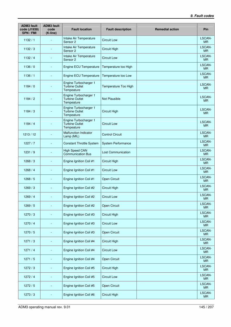
9. Fault codes
ADM3 operating manual rev. 9.01 145 / 207
ADM3 fault code (J1939)
SPN / FMI
ADM3 fault code
(K-line) Fault location Fault description Remedial action Pin
1132 / 1 - Intake Air Temperature Sensor 2
Circuit Low LSCAN-
MR
1132 / 3 - Intake Air Temperature Sensor 2
Circuit High LSCAN-
MR
1132 / 4 - Intake Air Temperature Sensor 2
Circuit Low LSCAN-
MR
1136 / 0 - Engine ECU Temperature Temperature too High LSCAN-
MR
1136 / 1 - Engine ECU Temperature Temperature too Low LSCAN-
MR
1184 / 0 - Engine Turbocharger 1 Turbine Outlet Tempeature
Temperature Too High LSCAN-
MR
1184 / 2 - Engine Turbocharger 1 Turbine Outlet Tempeature
Not Plausible LSCAN-
MR
1184 / 3 - Engine Turbocharger 1 Turbine Outlet Tempeature
Circuit High LSCAN-
MR
1184 / 4 - Engine Turbocharger 1 Turbine Outlet Tempeature
Circuit Low LSCAN-
MR
1213 / 12 - Malfunction Indicator Lamp (MIL)
Control Circuit LSCAN-
MR
1227 / 7 - Constant Throttle System System Performance LSCAN-
MR
1231 / 9 - High Speed CAN Communication Bus
Lost Communication LSCAN-
MR
1268 / 3 - Engine Ignition Coil #1 Circuit High LSCAN-
MR
1268 / 4 - Engine Ignition Coil #1 Circuit Low LSCAN-
MR
1268 / 5 - Engine Ignition Coil #1 Open Circuit LSCAN-
MR
1269 / 3 - Engine Ignition Coil #2 Circuit High LSCAN-
MR
1269 / 4 - Engine Ignition Coil #2 Circuit Low LSCAN-
MR
1269 / 5 - Engine Ignition Coil #2 Open Circuit LSCAN-
MR
1270 / 3 - Engine Ignition Coil #3 Circuit High LSCAN-
MR
1270 / 4 - Engine Ignition Coil #3 Circuit Low LSCAN-
MR
1270 / 5 - Engine Ignition Coil #3 Open Circuit LSCAN-
MR
1271 / 3 - Engine Ignition Coil #4 Circuit High LSCAN-
MR
1271 / 4 - Engine Ignition Coil #4 Circuit Low LSCAN-
MR
1271 / 5 - Engine Ignition Coil #4 Open Circuit LSCAN-
MR
1272 / 3 - Engine Ignition Coil #5 Circuit High LSCAN-
MR
1272 / 4 - Engine Ignition Coil #5 Circuit Low LSCAN-
MR
1272 / 5 - Engine Ignition Coil #5 Open Circuit LSCAN-
MR
1273 / 3 - Engine Ignition Coil #6 Circuit High LSCAN-
MR

9. Fault codes
146 / 207 ADM3 operating manual rev. 9.01
ADM3 fault code (J1939)
SPN / FMI
ADM3 fault code
(K-line) Fault location Fault description Remedial action Pin
1273 / 4 - Engine Ignition Coil #6 Circuit Low LSCAN-
MR
1273 / 5 - Engine Ignition Coil #6 Open Circuit LSCAN-
MR
1387 / 2 - Reductant Pressure Sensor
Circuit Range/Performance
LSCAN-
MR
1387 / 3 - Reductant Pressure Sensor
Circuit High LSCAN-
MR
1387 / 4 - Reductant Pressure Sensor
Circuit Low LSCAN-
MR
1390 / 0 - Engine Fuel Valve 1 Inlet Absolute Pressure
Above Measuring Range
LSCAN-
MR
1390 / 1 - Engine Fuel Valve 1 Inlet Absolute Pressure
Below Measuring Range
LSCAN-
MR
1390 / 17 - Engine Fuel Valve 1 Inlet Absolute Pressure
Too Low LSCAN-
MR
1623 / 9 19009 Tachograph Output Shaft Speed
Abnormal Update Rate CAN-J1939
1623 / 19 19019 Tachograph Output Shaft Speed
Received Network Data in Error
CAN-J1939
1624 / 9 19109 Tachograph Vehicle Speed
Abnormal Update Rate CAN-J1939
1624 / 19 19119 Tachograph Vehicle Speed
Received Network Data in Error
CAN-J1939
1633 / 9 19209 Cruise Control Pause Switch
Abnormal Update Rate CAN-J1939
1633 / 14 19214 Cruise Control Pause Switch
Plausibility Check Failed (Check Stalk Switch Wiring)
- Check wiring of stalk switch - Check parameter 13/37
18/06 and 12/07
1633 / 19 19219 Cruise Control Pause Switch
Received Network Data in Error
CAN-J1939
1636 / 3 - Ambient Air Combi Sensor, Part Temperature
Circuit High LSCAN-
MR
1636 / 4 - Ambient Air Combi Sensor, Part Temperature
Circuit Low LSCAN-
MR
1695 / 0 -
Engine Exhaust Gas Oxygen Sensor (Lambda Sensor) Fueling Correction
Control Deviation Too High
LSCAN-
MR
1695 / 2 -
Engine Exhaust Gas Oxygen Sensor (Lambda Sensor) Fueling Correction
Drift Not Plausible LSCAN-
MR
1716 / 9 19309 Retarder Selection, non-engine
Abnormal Update Rate CAN-J1939
1716 / 19 19319 Retarder Selection, non-engine
Received Network Data in Error
CAN-J1939
1761 / 1 - Reductant Level Level Low LSCAN-
MR
1761 / 3 - Reductant Level Sensor Circuit High LSCAN-
MR
1761 / 4 - Reductant Level Sensor Circuit Low LSCAN-
MR
1908 / 3 - SCR Air Pressure Shut-Off Valve Solenoid
Circuit High LSCAN-
MR
1908 / 4 - SCR Air Pressure Shut-Off Valve Solenoid
Circuit Low LSCAN-
MR
1908 / 5 - SCR Air Pressure Shut-Off Valve Solenoid
Circuit Open LSCAN-
MR
2436 / 9 - Generator Speed Sensing Signal-Timeout LSCAN-
MR
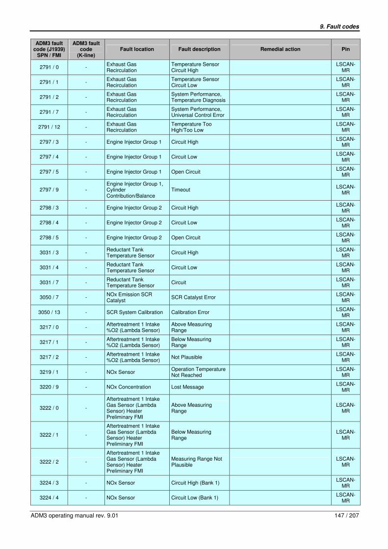
9. Fault codes
ADM3 operating manual rev. 9.01 147 / 207
ADM3 fault code (J1939)
SPN / FMI
ADM3 fault code
(K-line) Fault location Fault description Remedial action Pin
2791 / 0 - Exhaust Gas Recirculation
Temperature Sensor Circuit High
LSCAN-
MR
2791 / 1 - Exhaust Gas Recirculation
Temperature Sensor Circuit Low
LSCAN-
MR
2791 / 2 - Exhaust Gas Recirculation
System Performance, Temperature Diagnosis
LSCAN-
MR
2791 / 7 - Exhaust Gas Recirculation
System Performance, Universal Control Error
LSCAN-
MR
2791 / 12 - Exhaust Gas Recirculation
Temperature Too High/Too Low
LSCAN-
MR
2797 / 3 - Engine Injector Group 1 Circuit High LSCAN-
MR
2797 / 4 - Engine Injector Group 1 Circuit Low LSCAN-
MR
2797 / 5 - Engine Injector Group 1 Open Circuit LSCAN-
MR
2797 / 9 - Engine Injector Group 1, Cylinder Contribution/Balance
Timeout LSCAN-
MR
2798 / 3 - Engine Injector Group 2 Circuit High LSCAN-
MR
2798 / 4 - Engine Injector Group 2 Circuit Low LSCAN-
MR
2798 / 5 - Engine Injector Group 2 Open Circuit LSCAN-
MR
3031 / 3 - Reductant Tank Temperature Sensor
Circuit High LSCAN-
MR
3031 / 4 - Reductant Tank Temperature Sensor
Circuit Low LSCAN-
MR
3031 / 7 - Reductant Tank Temperature Sensor
Circuit LSCAN-
MR
3050 / 7 - NOx Emission SCR Catalyst
SCR Catalyst Error LSCAN-
MR
3050 / 13 - SCR System Calibration Calibration Error LSCAN-
MR
3217 / 0 - Aftertreatment 1 Intake %O2 (Lambda Sensor)
Above Measuring Range
LSCAN-
MR
3217 / 1 - Aftertreatment 1 Intake %O2 (Lambda Sensor)
Below Measuring Range
LSCAN-
MR
3217 / 2 - Aftertreatment 1 Intake %O2 (Lambda Sensor)
Not Plausible LSCAN-
MR
3219 / 1 - NOx Sensor Operation Temperature Not Reached
LSCAN-
MR
3220 / 9 - NOx Concentration Lost Message LSCAN-
MR
3222 / 0 -
Aftertreatment 1 Intake Gas Sensor (Lambda Sensor) Heater Preliminary FMI
Above Measuring Range
LSCAN-
MR
3222 / 1 -
Aftertreatment 1 Intake Gas Sensor (Lambda Sensor) Heater Preliminary FMI
Below Measuring Range
LSCAN-
MR
3222 / 2 -
Aftertreatment 1 Intake Gas Sensor (Lambda Sensor) Heater Preliminary FMI
Measuring Range Not Plausible
LSCAN-
MR
3224 / 3 - NOx Sensor Circuit High (Bank 1) LSCAN-
MR
3224 / 4 - NOx Sensor Circuit Low (Bank 1) LSCAN-
MR
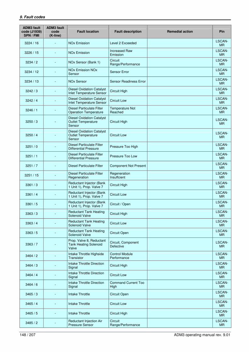
9. Fault codes
148 / 207 ADM3 operating manual rev. 9.01
ADM3 fault code (J1939)
SPN / FMI
ADM3 fault code
(K-line) Fault location Fault description Remedial action Pin
3224 / 16 - NOx Emission Level 2 Exceeded LSCAN-
MR
3226 / 15 - NOx Emission Increased Raw Emission
LSCAN-
MR
3234 / 2 - NOx Sensor (Bank 1) Circuit Range/Performance
LSCAN-
MR
3234 / 12 - NOx Emission NOx Sensor
Sensor Error LSCAN-
MR
3234 / 13 - NOx Sensor Sensor Readiness Error LSCAN-
MR
3242 / 3 - Diesel Oxidation Catalyst Inlet Temperature Sensor
Circuit High LSCAN-
MR
3242 / 4 - Diesel Oxidation Catalyst Inlet Temperature Sensor
Circuit Low LSCAN-
MR
3246 / 1 - Diesel Particulate Filter Operation Temperature
Temperature Not Reached
LSCAN-
MR
3250 / 3 - Diesel Oxidation Catalyst Outlet Temperature Sensor
Circuit High LSCAN-
MR
3250 / 4 - Diesel Oxidation Catalyst Outlet Temperature Sensor
Circuit Low LSCAN-
MR
3251 / 0 - Diesel Particulate Filter Differential Pressure
Pressure Too High LSCAN-
MR
3251 / 1 - Diesel Particulate Filter Differential Pressure
Pressure Too Low LSCAN-
MR
3251 / 7 - Diesel Particulate Filter Component Not Present LSCAN-
MR
3251 / 15 - Diesel Particulate Filter Regeneration
Regeneration Insuffcient
LSCAN-
MR
3361 / 3 - Reductant Injector (Bank 1 Unit 1), Prop. Valve 7
Circuit High LSCAN-
MR
3361 / 4 - Reductant Injector (Bank 1 Unit 1), Prop. Valve 7
Circuit Low LSCAN-
MR
3361 / 5 - Reductant Injector (Bank 1 Unit 1), Prop. Valve 7
Circuit / Open LSCAN-
MR
3363 / 3 - Reductant Tank Heating Solenoid Valve
Circuit High LSCAN-
MR
3363 / 4 - Reductant Tank Heating Solenoid Valve
Circuit Low LSCAN-
MR
3363 / 5 - Reductant Tank Heating Solenoid Valve
Circuit Open LSCAN-
MR
3363 / 7 - Prop. Valve 8, Reductant Tank Heating Solenoid Valve
Circuit, Component Defective
LSCAN-
MR
3464 / 2 - Intake Throttle Highside Transistor
Control Module Performance
LSCAN-
MR
3464 / 3 - Intake Throttle Direction Signal
Circuit High LSCAN-
MR
3464 / 4 - Intake Throttle Direction Signal
Circuit Low LSCAN-
MR
3464 / 6 - Intake Throttle Direction Signal
Command Current Too High
LSCAN-
MR
3465 / 3 - Intake Throttle Circuit Open LSCAN-
MR
3465 / 4 - Intake Throttle Circuit Low LSCAN-
MR
3465 / 5 - Intake Throttle Circuit High LSCAN-
MR
3485 / 2 - Reductant Injection Air Pressure Sensor
Circuit Range/Performance
LSCAN-
MR

9. Fault codes
ADM3 operating manual rev. 9.01 149 / 207
ADM3 fault code (J1939)
SPN / FMI
ADM3 fault code
(K-line) Fault location Fault description Remedial action Pin
3485 / 3 - Reductant Injection Air Pressure Sensor
Circuit High LSCAN-
MR
3485 / 4 - Reductant Injection Air Pressure Sensor
Circuit Low LSCAN-
MR
3509 / 2 - 5V Output Reference Voltage 1
Voltage Too High/Too Low
LSCAN-
MR
3510 / 2 - 5V Output Reference Voltage 2
Voltage Too High/Too Low
LSCAN-
MR
3511 / 5 - Sensor Reference Voltage “A”
Circuit Open LSCAN-
MR
3512 / 5 - Sensor Reference Voltage “B”
Circuit Open LSCAN-
MR
3513 / 5 - Sensor Reference Voltage “C”
Circuit Open LSCAN-
MR
3515 / 3 - Reductant Temperature Sensor
Circuit High Input LSCAN-
MR
3515 / 4 - Reductant Temperature Sensor
Circuit Low Input LSCAN-
MR
3516 / 1 - NOx Emission Reducant Dosing
Unsufficient Reductant Dosing
LSCAN-
MR
3516 / 14 - NOx Emission Reductant Dosing
Reductant Quality/Unsufficient Reductant Dosing/SCR Catalyst Error
LSCAN-
MR
3516 / 18 - NOx Emission Reductant Dosing
Reductant Quality/Unsufficient Reductant Dosing
LSCAN-
MR
3520 / 18 - NOx Emission Reductant Reductant Quality LSCAN-
MR
3597 / 2 - Proportional Valve Bank 1 Control Module Performance
LSCAN-
MR
3597 / 3 - Proportional Valve Bank 1 Circuit High LSCAN-
MR
3597 / 4 - Proportional Valve Bank 1 Circuit Low LSCAN-
MR
3605 / 3 - Coolant Pump Control Circuit High LSCAN-
MR
3605 / 4 - Coolant Pump Control Circuit Low LSCAN-
MR
3605 / 5 - Coolant Pump Control Circuit Open LSCAN-
MR
3609 / 2 - Diesel Particulate Filter Inlet Pressure Sensor
Circuit Range/Performance
LSCAN-
MR
3609 / 3 - Diesel Particulate Filter Inlet Pressure Sensor
Circuit High LSCAN-
MR
3609 / 4 - Diesel Particulate Filter Inlet Pressure Sensor
Circuit Low LSCAN-
MR
3610 / 2 - Diesel Particulate Filter Outlet Pressure Sensor
Circuit Range/Performance
LSCAN-
MR
3610 / 3 - Diesel Particulate Filter Outlet Pressure Sensor
Circuit High LSCAN-
MR
3610 / 4 - Diesel Particulate Filter Outlet Pressure Sensor
Circuit Low LSCAN-
MR
3673 / 0 - Engine Throttle Position 2 Above Measuring Range
LSCAN-
MR
3673 / 1 - Engine Throttle Position 2 Below Measuring Range
LSCAN-
MR
3673 / 2 - Engine Throttle Position 2 Measuring Range Not Plausible
LSCAN-
MR
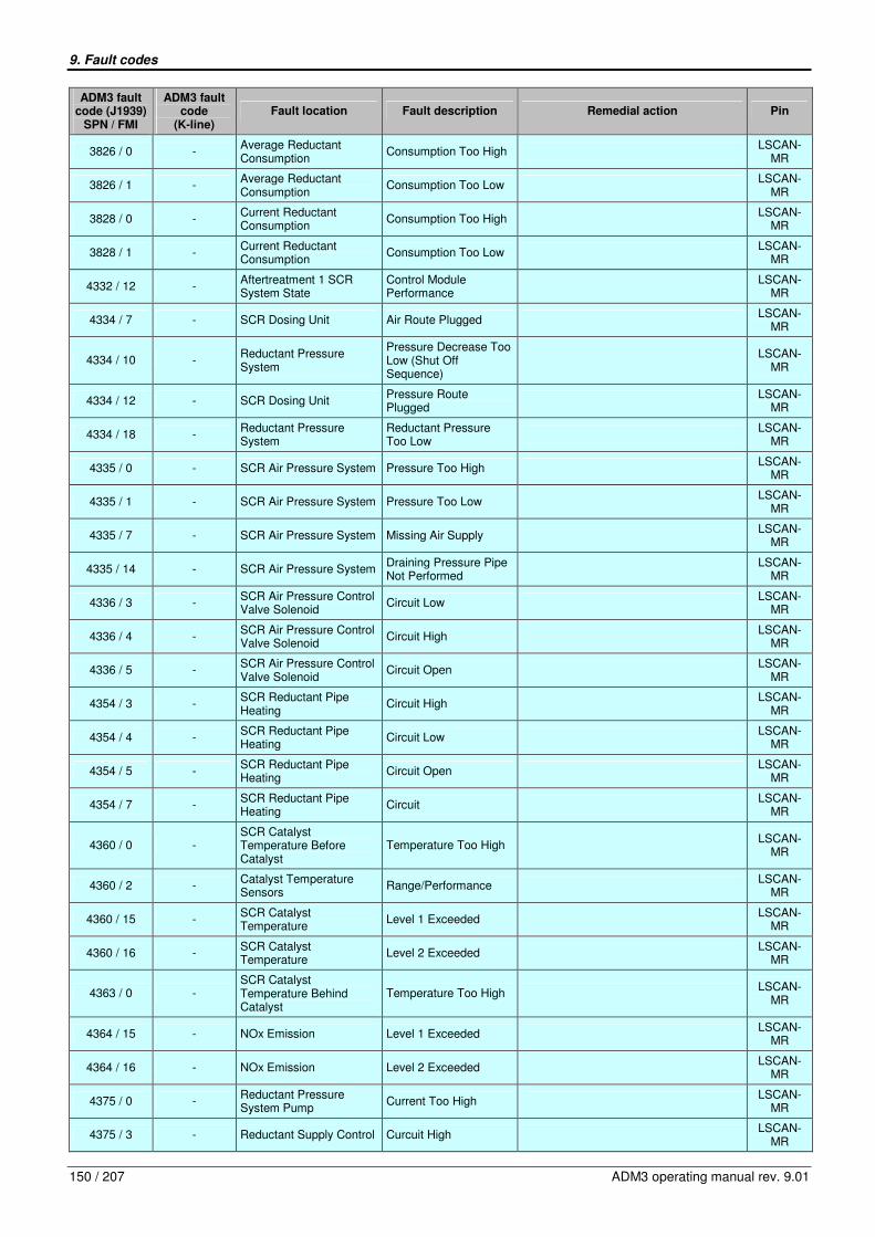
9. Fault codes
150 / 207 ADM3 operating manual rev. 9.01
ADM3 fault code (J1939)
SPN / FMI
ADM3 fault code
(K-line) Fault location Fault description Remedial action Pin
3826 / 0 - Average Reductant Consumption
Consumption Too High LSCAN-
MR
3826 / 1 - Average Reductant Consumption
Consumption Too Low LSCAN-
MR
3828 / 0 - Current Reductant Consumption
Consumption Too High LSCAN-
MR
3828 / 1 - Current Reductant Consumption
Consumption Too Low LSCAN-
MR
4332 / 12 - Aftertreatment 1 SCR System State
Control Module Performance
LSCAN-
MR
4334 / 7 - SCR Dosing Unit Air Route Plugged LSCAN-
MR
4334 / 10 - Reductant Pressure System
Pressure Decrease Too Low (Shut Off Sequence)
LSCAN-
MR
4334 / 12 - SCR Dosing Unit Pressure Route Plugged
LSCAN-
MR
4334 / 18 - Reductant Pressure System
Reductant Pressure Too Low
LSCAN-
MR
4335 / 0 - SCR Air Pressure System Pressure Too High LSCAN-
MR
4335 / 1 - SCR Air Pressure System Pressure Too Low LSCAN-
MR
4335 / 7 - SCR Air Pressure System Missing Air Supply LSCAN-
MR
4335 / 14 - SCR Air Pressure System Draining Pressure Pipe Not Performed
LSCAN-
MR
4336 / 3 - SCR Air Pressure Control Valve Solenoid
Circuit Low LSCAN-
MR
4336 / 4 - SCR Air Pressure Control Valve Solenoid
Circuit High LSCAN-
MR
4336 / 5 - SCR Air Pressure Control Valve Solenoid
Circuit Open LSCAN-
MR
4354 / 3 - SCR Reductant Pipe Heating
Circuit High LSCAN-
MR
4354 / 4 - SCR Reductant Pipe Heating
Circuit Low LSCAN-
MR
4354 / 5 - SCR Reductant Pipe Heating
Circuit Open LSCAN-
MR
4354 / 7 - SCR Reductant Pipe Heating
Circuit LSCAN-
MR
4360 / 0 - SCR Catalyst Temperature Before Catalyst
Temperature Too High LSCAN-
MR
4360 / 2 - Catalyst Temperature Sensors
Range/Performance LSCAN-
MR
4360 / 15 - SCR Catalyst Temperature
Level 1 Exceeded LSCAN-
MR
4360 / 16 - SCR Catalyst Temperature
Level 2 Exceeded LSCAN-
MR
4363 / 0 - SCR Catalyst Temperature Behind Catalyst
Temperature Too High LSCAN-
MR
4364 / 15 - NOx Emission Level 1 Exceeded LSCAN-
MR
4364 / 16 - NOx Emission Level 2 Exceeded LSCAN-
MR
4375 / 0 - Reductant Pressure System Pump
Current Too High LSCAN-
MR
4375 / 3 - Reductant Supply Control Curcuit High LSCAN-
MR

9. Fault codes
ADM3 operating manual rev. 9.01 151 / 207
ADM3 fault code (J1939)
SPN / FMI
ADM3 fault code
(K-line) Fault location Fault description Remedial action Pin
4375 / 4 - Reductant Supply Control Curcuit Low LSCAN-
MR
4375 / 5 - Reductant Supply Control Curcuit Open LSCAN-
MR
4794 / 14 - Aftertreatment 1 SCR Catalyst System
Component Not Present LSCAN-
MR
4809 / 3 - Catalyst Temperature Sensor (Bank 1 Sensor 1)
Circuit High Input LSCAN-
MR
4809 / 4 - Catalyst Temperature Sensor (Bank 1 Sensor 1)
Circuit Low Input LSCAN-
MR
4810 / 3 - Catalyst Temperature Sensor (Bank 1 Sensor 2)
Circuit High LSCAN-
MR
4810 / 4 - Catalyst Temperature Sensor (Bank 1 Sensor 2)
Circuit Low LSCAN-
MR
520192 / 9 19409 Engine Start Stop Signals Abnormal Update Rate CAN-J1939
520192 / 19 19419 Engine Start Stop Signals Received Network Data in Error
CAN-J1939
520230 / 0 - SCR Pressure Accumulator Bubble Pressure
Pressure Too High LSCAN-
MR
520230 / 2 - SCR Pressure Accumulator Bubble Pressure
Pressure Outside Range
LSCAN-
MR
520258 / 7 - SCRT System Component
Component Not Present LSCAN-
MR
520259 / 2 - SCRT Temperature Sensors Pair A
Circuit Range/Performance
LSCAN-
MR
520260 / 2 - SCRT Temperature Sensors Pair B
Circuit Range/Performance
LSCAN-
MR
520262 / 14 - SCR System EGA Disabled Mannhem- or Wörth-Function
LSCAN-
MR
520263 / 9 - Automatic Compression Detection Function
Timeout LSCAN-
MR
520263 / 14 - Automatic Compression Detection Function
Cancelling LSCAN-
MR

9. Fault codes
152 / 207 ADM3 operating manual rev. 9.01
9.2. Fault codes listed by K-line code
ADM3 fault code
(K-line)
ADM3 fault code (J1939)
SPN / FMI Fault location Fault description
10003 1072 / 3 Decompression Brake Valve (MBR_KD) Open Circuit
10004 1072 / 4 Decompression Brake Valve (MBR_KD) Short Circuit to Ground
10103 84 / 3 Vehicle Speed (C3 or J1939) Open Circuit
10109 84 / 9 Vehicle Speed (C3 or J1939) Abnormal Update Rate
10114 84 / 14 Vehicle Speed (C3 or J1939) Signal Not Plausible
10119 84 / 19 Vehicle Speed (C3 or J1939) Received Network Data in Error
10200 91 / 0 Accelerator Pedal (AFPS or J1939) Not Adjusted
10203 91 / 3 Accelerator Pedal (AFPS or J1939) Voltage too High
10204 91 / 4 Accelerator Pedal (AFPS or J1939) Voltage too Low
10209 91 / 9 Accelerator Pedal (AFPS or J1939) Abnormal Update Rate
10219 91 / 19 Accelerator Pedal (AFPS or J1939) Received Network Data in Error
10400 98 / 0 Oil Level (from PLD/MR2) Oil Level too High
10401 98 / 1 Oil Level (from PLD/MR2) Low Oil Level
10414 98 / 14 Oil Level (from PLD/MR2) Oil Level too Low
10501 100 / 1 Oil Pressure (from PLD/MR2) Low Oil Pressure
10514 100 / 14 Oil Pressure (from PLD/MR2) Oil Pressure too Low
10800 107 / 0 Air Filter Sensor (LF_SE) Differential Pressure too High
10803 107 / 3 Air Filter Sensor (LF_SE) Open Circuit
10804 107 / 4 Air Filter Sensor (LF_SE) Short Circuit to Ground
10914 110 / 14 Coolant Temperature (from PLD/MR2) Coolant Temperature too High
11001 111 / 1 Coolant Level Sensor (KW_SE) Low Coolant Level
11003 111 / 3 Coolant Level Sensor (KW_SE) Open Circuit
11004 111 / 4 Coolant Level Sensor (KW_SE) Short Circuit to Ground
11014 111 / 14 Coolant Level Sensor (KW_SE) Coolant Level too Low
11100 158 / 0 Battery Voltage Switched (Terminal 15) Over Voltage
11101 158 / 1 Battery Voltage Switched (Terminal 15) Under Voltage
11701 558 / 1 Accelerator Pedal Idle Switch (GAS1 + GAS2 or J1939)
Both Signals Equal but Should not
11705 558 / 5 Accelerator Pedal Idle Switch (GAS1 + GAS2 or J1939)
Both Switches Open Circuit
11709 558 / 9 Accelerator Pedal Idle Switch (GAS1 + GAS2 or J1939)
Abnormal Update Rate
11712 558 / 12 Accelerator Pedal Idle Switch (GAS1 + GAS2 or J1939)
Both Switches Closed
11719 558 / 19 Accelerator Pedal Idle Switch (GAS1 + GAS2 or J1939)
Received Network Data in Error
11809 599 / 9 Cruise Control Switch CC- (Set + Coast) Abnormal Update Rate (Set Switch)
11812 599 / 12 Cruise Control Switch CC- (Set + Coast) Both Switches CC- and CC+ Closed
11814 599 / 14 Cruise Control Switch CC- (Set + Coast) Plausibility Check Failed (Check Stalk Switch Wiring)
11819 599 / 19 Cruise Control Switch CC- (Set + Coast) Received Network Data in Error
11909 601 / 9 Cruise Control Switch CC+ (Res + Acc) Abnormal Update Rate (Resume Switch)
11912 601 / 12 Cruise Control Switch CC+ (Res + Acc) Both Switches CC+ and CC- closed
11914 601 / 14 Cruise Control Switch CC+ (Res + Acc) Plausibility Check Failed (Check Stalk Switch Wiring)
11919 601 / 19 Cruise Control Switch CC+ (Res + Acc) Received Network Data in Error
12002 609 / 2 PLD/MR2 Error Unknown Cause
12103 620 / 3 Supply Analog Accelerator Pedal (AFP+) Voltage too High
12104 620 / 4 Supply Analog Accelerator Pedal (AFP+) Voltage too Low
12202 625 / 2 CAN Link ADM3 – PLD/MR2 No Communication with PLD/MR2
13303 677 / 3 Output Relay 1 (REL 1) Open Circuit

9. Fault codes
ADM3 operating manual rev. 9.01 153 / 207
ADM3 fault code
(K-line)
ADM3 fault code (J1939)
SPN / FMI Fault location Fault description
13304 677 / 4 Output Relay 1 (REL 1) Short Circuit to Ground
13900 730 / 0 Output Relay 2 (REL 2) Grid Heater: No Increasing Boost Temperature After Activation
13901 730 / 1 Output Relay 2 (REL 2) Grid Heater: Relay Permanently Closed
13902 730 / 2 Output Relay 2 (REL 2) Grid Heater: Relay Permanently Open
13903 730 / 3 Output Relay 2 (REL 2) Voltage too High when Activated
13904 730 / 4 Output Relay 2 (REL 2) Voltage too Low when Activated
14003 729 / 3 Intake Air Heater (MBR_KD) Open Circuit
14004 729 / 4 Intake Air Heater (MBR_KD) Short Circuit to Ground
14202 974 / 2 Remote Throttle Pedal (HFG) Supply Voltage Out of Range (Pin HFG+)
14203 974 / 3 Remote Throttle Pedal (HFG) Voltage too High
14204 974 / 4 Remote Throttle Pedal (HFG) Voltage too Low
14403 1004 / 3 Output Relay 4 (REL 4) Open circuit
14404 1004 / 4 Output Relay 4 (REL 4) Short Circuit to Ground
14503 1005 / 3 Output PWM Pedal Supply or Transmission (FP+) Open Circuit
14504 1005 / 4 Output PWM Pedal Supply or Transmission (FP+) Short Circuit to Ground
14603 1074 / 3 Exhaust Brake Valve (MBR_BK) Open Circuit
14604 1074 / 4 Exhaust Brake Valve (MBR_BK) Short Circuit to Ground
14902 639 / 2 SAE J1939 Interface At Least One J1939 Message is Missing
15001 1015 / 1 PWM Accelerator Pedal (PWM FFG) No Supply Voltage at Pin FP+
15003 1015 / 3 PWM Accelerator Pedal (PWM FFG) No Signal at Path 2 (GAS2)
15004 1015 / 4 PWM Accelerator Pedal (PWM FFG) No Signal at Path 1 (GAS1)
15005 1015 / 5 PWM Accelerator Pedal (PWM FFG) Not Adjusted
15006 1015 / 6 PWM Accelerator Pedal (PWM FFG) Idle Position Out of Adjusted Range
15007 1015 / 7 PWM Accelerator Pedal (PWM FFG) Out of Adjusted Range
16609 171 / 9 Ambient Air Temperature Abnormal Update Rate
16619 171 / 19 Ambient Air Temperature Received Network Data in Error
17309 69 / 9 Two Speed Axle Switch Abnormal Update Rate
17319 69 / 19 Two Speed Axle Switch Received Network Data in Error
17409 70 / 9 Parking Brake Switch Abnormal Update Rate
17419 70 / 19 Parking Brake Switch Received Network Data in Error
17509 96 / 9 Fuel Level Abnormal Update Rate
17519 96 / 19 Fuel Level Received Network Data in Error
17609 161 / 9 Transmission Input Shaft Speed Abnormal Update Rate
17619 161 / 19 Transmission Input Shaft Speed Received Network Data in Error
17709 191 / 9 Transmission Output Shaft Speed Abnormal Update Rate
17719 191 / 19 Transmission Output Shaft Speed Received Network Data in Error
17809 523 / 9 Transmission Current Gear Abnormal Update Rate
17819 523 / 19 Transmission Current Gear Received Network Data in Error
17909 524 / 9 Transmission Selected Gear Abnormal Update Rate
17919 524 / 19 Transmission Selected Gear Received Network Data in Error
18009 559 / 9 Accelerator Pedal Kickdown Switch Abnormal Update Rate
18019 559 / 19 Accelerator Pedal Kickdown Switch Received Network Data in Error
18109 573 / 9 Transmission Torque Converter Lockup Engaged Abnormal Update Rate
18119 573 / 19 Transmission Torque Converter Lockup Engaged Received Network Data in Error
18209 574 / 9 Transmission Shift in Process Abnormal Update Rate
18219 574 / 19 Transmission Shift in Process Received Network Data in Error
18309 596 / 9 Cruise Control Enable Switch Abnormal Update Rate
18319 596 / 19 Cruise Control Enable Switch Received Network Data in Error
18409 597 / 9 Brake Switch Abnormal Update Rate
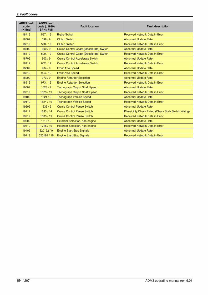
9. Fault codes
154 / 207 ADM3 operating manual rev. 9.01
ADM3 fault code
(K-line)
ADM3 fault code (J1939)
SPN / FMI Fault location Fault description
18419 597 / 19 Brake Switch Received Network Data in Error
18509 598 / 9 Clutch Switch Abnormal Update Rate
18519 598 / 19 Clutch Switch Received Network Data in Error
18609 600 / 9 Cruise Control Coast (Decelerate) Switch Abnormal Update Rate
18619 600 / 19 Cruise Control Coast (Decelerate) Switch Received Network Data in Error
18709 602 / 9 Cruise Control Accelerate Switch Abnormal Update Rate
18719 602 / 19 Cruise Control Accelerate Switch Received Network Data in Error
18809 904 / 9 Front Axle Speed Abnormal Update Rate
18819 904 / 19 Front Axle Speed Received Network Data in Error
18909 973 / 9 Engine Retarder Selection Abnormal Update Rate
18919 973 / 19 Engine Retarder Selection Received Network Data in Error
19009 1623 / 9 Tachograph Output Shaft Speed Abnormal Update Rate
19019 1623 / 19 Tachograph Output Shaft Speed Received Network Data in Error
19109 1624 / 9 Tachograph Vehicle Speed Abnormal Update Rate
19119 1624 / 19 Tachograph Vehicle Speed Received Network Data in Error
19209 1633 / 9 Cruise Control Pause Switch Abnormal Update Rate
19214 1633 / 14 Cruise Control Pause Switch Plausibility Check Failed (Check Stalk Switch Wiring)
19219 1633 / 19 Cruise Control Pause Switch Received Network Data in Error
19309 1716 / 9 Retarder Selection, non-engine Abnormal Update Rate
19319 1716 / 19 Retarder Selection, non-engine Received Network Data in Error
19409 520192 / 9 Engine Start Stop Signals Abnormal Update Rate
19419 520192 / 19 Engine Start Stop Signals Received Network Data in Error
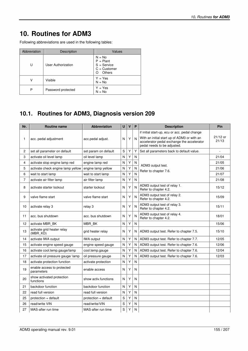
10. Routines for ADM3
ADM3 operating manual rev. 9.01 155 / 207
10. Routines for ADM3 Following abbreviations are used in the following tables:
Abbreviation Description Values
U User Authorization
N = No P = Plant S = Service C = Customer O Others
V Visible Y = Yes N = No
P Password protected Y = Yes N = No
10.1. Routines for ADM3, Diagnosis version 209
Nr. Routine name Abbreviation U V P Description Pin
1 acc. pedal adjustment acc.pedal adjust. N Y N
if initial start-up, ecu or acc. pedal change
With an initial start up of ADM3 or with an accelerator pedal exchange the accelerator pedal needs to be adjusted.
21/12 or 21/13
2 set all parameter on default set param on default S Y Y Set all parameters back to default value. -
3 activate oil level lamp oil level lamp N Y N 21/04
4 activate stop engine lamp red engine lamp red N Y N 21/05
5 activate check engine lamp yellow engine lamp yellow N Y N 21/06
6 wait to start lamp wait to start lamp N Y N 21/07
7 activate air filter lamp air filter lamp N Y N
ADM3 output test.
Refer to chapter 7.6.
21/08
8 activate starter lockout starter lockout N Y N ADM3 output test of relay 1. Refer to chapter 4.2.
15/12
9 valve flame start valve flame start N Y N ADM3 output test of relay 2. Refer to chapter 4.2.
15/09
10 activate relay 3 relay 3 N Y N ADM3 output test of relay 3. Refer to chapter 4.2.
15/11
11 acc. bus shutdown acc. bus shutdown N Y N ADM3 output test of relay 4. Refer to chapter 4.2.
18/01
12 activate MBR_BK MBR_BK N Y N 15/06
13 activate grid heater relay (MBR_KD)
grid heater relay N Y N ADM3 output test. Refer to chapter 7.5. 15/10
14 activate IWA output IWA output N Y N ADM3 output test. Refer to chapter 7.7. 12/05
15 activate engine speed gauge engine speed gauge N Y N ADM3 output test. Refer to chapter 7.6. 12/06
16 activate cool.temp.gauge/lamp cool.temp.gauge N Y N ADM3 output test. Refer to chapter 7.6. 12/04
17 activate oil pressure gauge/ lamp oil pressure gauge N Y N ADM3 output test. Refer to chapter 7.6. 12/03
18 activate protection function activate protection N Y N
19 enable access to protected parameters
enable access N Y N
20 show activated protection functions
show activ.functions N Y N
21 backdoor function backdoor function N Y N
22 read full version read full version N Y N
25 protection + default protection + default S Y N
26 read/write VIN read/write/VIN S Y N
27 MAS-after run time MAS-after run time S Y N
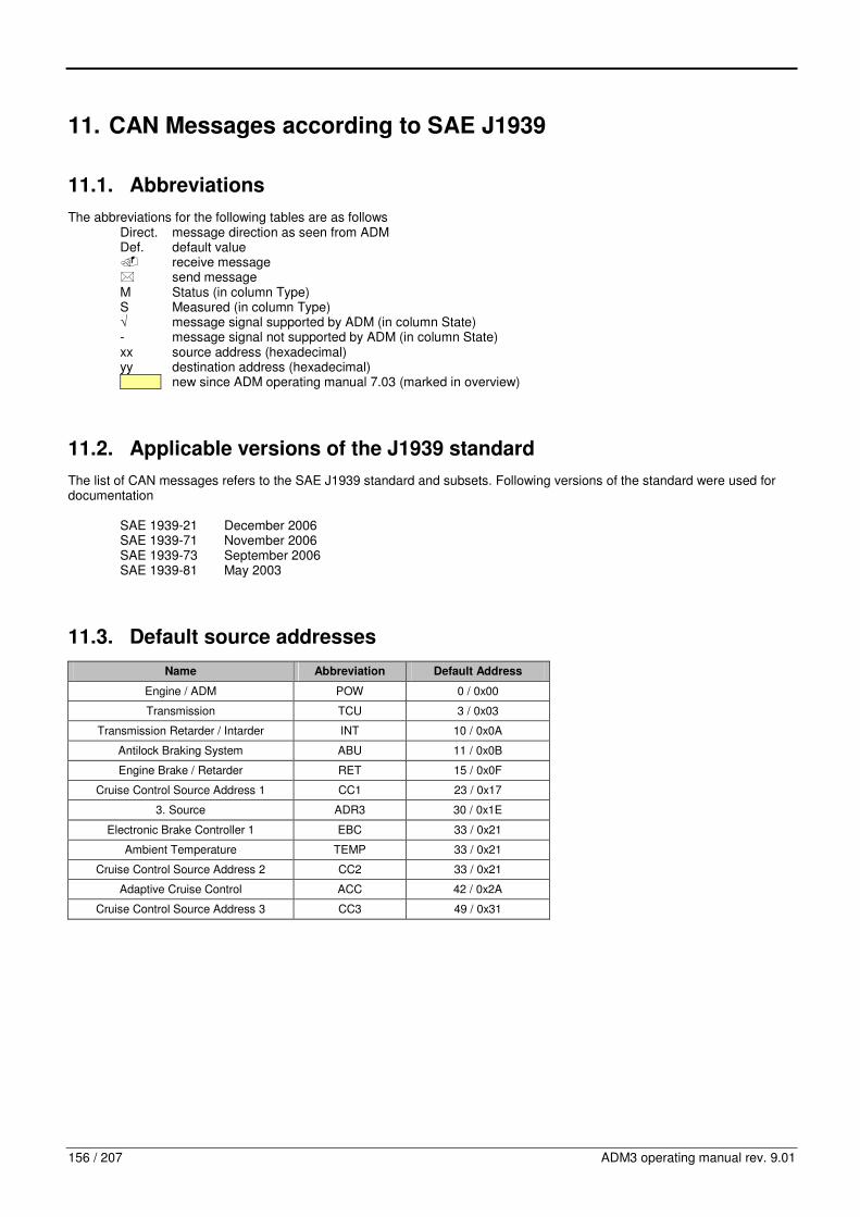
156 / 207 ADM3 operating manual rev. 9.01
11. CAN Messages according to SAE J1939
11.1. Abbreviations
The abbreviations for the following tables are as follows Direct. message direction as seen from ADM Def. default value � receive message � send message M Status (in column Type) S Measured (in column Type) √ message signal supported by ADM (in column State) - message signal not supported by ADM (in column State) xx source address (hexadecimal) yy destination address (hexadecimal) new since ADM operating manual 7.03 (marked in overview)
11.2. Applicable versions of the J1939 standard
The list of CAN messages refers to the SAE J1939 standard and subsets. Following versions of the standard were used for documentation SAE 1939-21 December 2006 SAE 1939-71 November 2006 SAE 1939-73 September 2006 SAE 1939-81 May 2003
11.3. Default source addresses
Name Abbreviation Default Address
Engine / ADM POW 0 / 0x00
Transmission TCU 3 / 0x03
Transmission Retarder / Intarder INT 10 / 0x0A
Antilock Braking System ABU 11 / 0x0B
Engine Brake / Retarder RET 15 / 0x0F
Cruise Control Source Address 1 CC1 23 / 0x17
3. Source ADR3 30 / 0x1E
Electronic Brake Controller 1 EBC 33 / 0x21
Ambient Temperature TEMP 33 / 0x21
Cruise Control Source Address 2 CC2 33 / 0x21
Adaptive Cruise Control ACC 42 / 0x2A
Cruise Control Source Address 3 CC3 49 / 0x31

11. CAN Messages according to SAE J1939
ADM3 operating manual rev. 9.01 157 / 207
11.4. Overview of J1939 CAN messages
11.4.1. Miscellaneous messages
Nr. Abbrev. Name Identifier PGN Sender Repetition rate Direct.
1 TSC1 Torque/Speed Control 1 (to
Engine) 0x0C00yyxx 0 / 0x0
xx = TCU, ABU, ADR3, ACC, yy = POW
10ms �
2 TSC1 Torque/Speed Control 1 (to
Retarder) 0x0C00yyxx 0 / 0x0
xx = TCU, ABU, ADR3, ACC,
yy = RET 50ms �
3 RESET Reset 0x1CDEyyxx 56832 / 0xDE00 xx = any,
yy = POW, RET when needed �
4 ACK / NACK
Acknowledgement: Acknowledge, Not
Acknowledge, Access Denied, Cannot Respond
0x18E8yyxx 59392 / 0xE800 xx = POW, RET,
yy = 0xFF (global)
upon reception of PGN that requires acknowledgment
�
5 REQ Request PG 0x18EAyyxx 59904 / 0xEA00 xx = any,
yy = 0xFF (global) per user
requirements �
6 TP.DT Transport Protocol – Data
Transfer 0x18EByyxx 60160 / 0xEB00
xx = POW, yy = TCU, ACC, any,
0xFF (global)
per PGN to be transferred
�
7 TP.CM Transport Protocol –
Connection Management 0x18ECyyxx 60416 / 0xEC00
xx = POW, yy = TCU, ACC, any,
0xFF (global)
per PGN to be transferred
�, �
8 ACL Address Claimed, Cannot Claim
Address 0x18EEFFxx 60928 / 0xEE00
xx = POW, RET, 0xFE (cannot claim)
as required �, �
9 ESS Proprietary A 0x0CEFyyxx 61184 / 0xEF00 xx = TCU, ABU,
ADR3, yy = POW
50ms �
10 KWP Proprietary A from Minidiag 0x0CEFyyxx 61184 / 0xEF00 xx = 0xF1 (Minidiag),
yy = POW request �
11 KWP Proprietary A to Minidiag 0x0CEFyyxx 61184 / 0xEF00 xx = POW,
yy = 0xF1 (Minidiag) on request �
12 PropA Proprietary A 0x0CEFyyxx 61184 / 0xEF00 xx = any, yy = POW
request �
13 ERC1 Electronic Retarder Controller 1 0x18F000xx 61440 / 0xF000 xx = INT 100ms �
14 ERC1 Electronic Retarder Controller 1 0x18F000xx 61440 / 0xF000 xx = RET 100ms �
15 EBC1 Electronic Brake Controller 1 0x18F001xx 61441 / 0xF001 xx = EBC 100ms �
16 EBC1 Electronic Brake Controller 1 0x18F001xx 61441 / 0xF001 xx = POW 100ms �
17 ETC1 Electronic Transmission
Controller 1 0x0CF002xx 61442 / 0xF002 xx = TCU 10ms �
18 EEC2 Electronic Engine Controller 2 0x0CF003xx 61443 / 0xF003 xx = 0x01 (upper structure), ADR3,
0x21 (body controller) 50ms, on request �
19 EEC2 Electronic Engine Controller 2 0x0CF003xx 61443 / 0xF003 xx = POW 50ms, on request �
20 EEC1 Electronic Engine Controller 1 0x0CF004xx 61444 / 0xF004 xx = POW 10ms, on request �
21 ETC2 Electronic Transmission
Controller 2 0x18F005xx 61445 / 0xF005 xx = TCU 100ms �
22 ETC7 Electronic Transmission
Controller 7 0x18FE4Axx 65098 / 0xFE4A xx = TCU 100ms �
23 TI1 Tank Information 1 0x18FE56xx 65110 / 0xFE56 xx = POW 1s �
24 TCO1 Tachograph 0x0CFE6Cxx 65132 / 0xFE6C xx = any (tachograph) 50ms �
25 ACC1 Adaptive Cruise Control 0x10FE6Fxx 65135 / 0xFE6F x = ACC 100ms �
26 EBC2 Wheel Speed Information 0x18FEBFxx 65215 / 0xFEBF xx =ABU 100ms �
27 AUXIO1 Auxiliary Input /Output Status 0x18FED9xx 65241 / 0xFED9 xx = POW 100ms �
28 SOFT Software Identification 0x18FEDAxx 65242 / 0xFEDA xx = POW on request �
29 EEC3 Electronic Engine Controller 3 0x18FEDFxx 65247 / 0xFEDF xx = POW 250ms, on request �
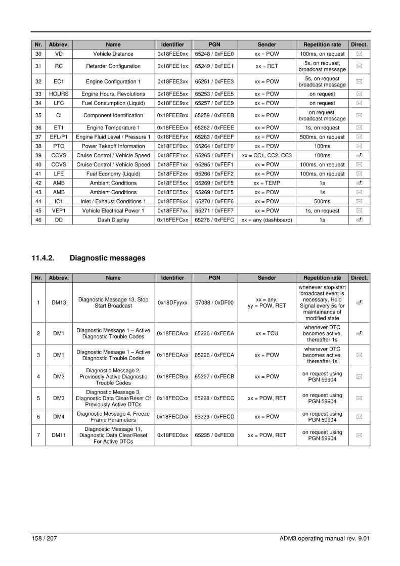
158 / 207 ADM3 operating manual rev. 9.01
Nr. Abbrev. Name Identifier PGN Sender Repetition rate Direct.
30 VD Vehicle Distance 0x18FEE0xx 65248 / 0xFEE0 xx = POW 100ms, on request �
31 RC Retarder Configuration 0x18FEE1xx 65249 / 0xFEE1 xx = RET 5s, on request,
broadcast message �
32 EC1 Engine Configuration 1 0x18FEE3xx 65251 / 0xFEE3 xx = POW 5s, on request
broadcast message �
33 HOURS Engine Hours, Revolutions 0x18FEE5xx 65253 / 0xFEE5 xx = POW on request �
34 LFC Fuel Consumption (Liquid) 0x18FEE9xx 65257 / 0xFEE9 xx = POW on request �
35 CI Component Identification 0x18FEEBxx 65259 / 0xFEEB xx = POW on request,
broadcast message �
36 ET1 Engine Temperature 1 0x18FEEExx 65262 / 0xFEEE xx = POW 1s, on request �
37 EFL/P1 Engine Fluid Level / Pressure 1 0x18FEEFxx 65263 / 0xFEEF xx = POW 500ms, on request �
38 PTO Power Takeoff Information 0x18FEF0xx 65264 / 0xFEF0 xx = POW 100ms �
39 CCVS Cruise Control / Vehicle Speed 0x18FEF1xx 65265 / 0xFEF1 xx = CC1, CC2, CC3 100ms �
40 CCVS Cruise Control / Vehicle Speed 0x18FEF1xx 65265 / 0xFEF1 xx = POW 100ms, on request �
41 LFE Fuel Economy (Liquid) 0x18FEF2xx 65266 / 0xFEF2 xx = POW 100ms, on request �
42 AMB Ambient Conditions 0x18FEF5xx 65269 / 0xFEF5 xx = TEMP 1s �
43 AMB Ambient Conditions 0x18FEF5xx 65269 / 0xFEF5 xx = POW 1s �
44 IC1 Inlet / Exhaust Conditions 1 0x18FEF6xx 65270 / 0xFEF6 xx = POW 500ms �
45 VEP1 Vehicle Electrical Power 1 0x18FEF7xx 65271 / 0xFEF7 xx = POW 1s, on request �
46 DD Dash Display 0x18FEFCxx 65276 / 0xFEFC xx = any (dashboard) 1s �
11.4.2. Diagnostic messages
Nr. Abbrev. Name Identifier PGN Sender Repetition rate Direct.
1 DM13 Diagnostic Message 13, Stop
Start Broadcast 0x18DFyyxx 57088 / 0xDF00
xx = any, yy = POW, RET
whenever stop/start broadcast event is necessary, Hold
Signal every 5s for maintainance of modified state
�
2 DM1 Diagnostic Message 1 – Active
Diagnostic Trouble Codes 0x18FECAxx 65226 / 0xFECA xx = TCU
whenever DTC becomes active,
thereafter 1s �
3 DM1 Diagnostic Message 1 – Active
Diagnostic Trouble Codes 0x18FECAxx 65226 / 0xFECA xx = POW
whenever DTC becomes active,
thereafter 1s �
4 DM2 Diagnostic Message 2,
Previously Active Diagnostic Trouble Codes
0x18FECBxx 65227 / 0xFECB xx = POW on request using
PGN 59904 �
5 DM3 Diagnostic Message 3,
Diagnostic Data Clear/Reset Of Previously Active DTCs
0x18FECCxx 65228 / 0xFECC xx = POW, RET on request using
PGN 59904 �
6 DM4 Diagnostic Message 4, Freeze
Frame Parameters 0x18FECDxx 65229 / 0xFECD xx = POW
on request using PGN 59904
�
7 DM11 Diagnostic Message 11,
Diagnostic Data Clear/Reset For Active DTCs
0x18FED3xx 65235 / 0xFED3 xx = POW, RET on request using
PGN 59904 �

11. CAN Messages according to SAE J1939
ADM3 operating manual rev. 9.01 159 / 207
11.5. CAN message details of miscellaneous messages
11.5.1. TSC1 – Torque/Speed Control 1 (to Engine)
Identifier Repetition rate Standard ADM Direction
0x0C00yyxx 10ms SAE J1939-71 �
Parameter Group Number
Data Length
Priority Extended Data Page
Data Page
PDU Format
PDU Specific Sender Address
0 = 0x0
8 3 0 0 0 Destination Address: yy = POW (Def. 0x00)
xx = TCU (Def. 0x03), ABU (Def. 0x0B), ADR3 (Def. 0x1E), ACC (Def. 0x2A)
Byte Bit Length Signal Name Spn Type Operating Data Range State
1 2,1 2 bits Engine Override Control Mode 695 S
00b .. 11b, 00 Override disabled – Disable any existing control commanded by the source of this command 01 Speed control – Govern speed to the included “desired speed” value 10 Torque control – Control torque to the included “desired torque” value 11 Speed/Torque limit control – Limit speed and/or torque based on the included limit values. The speed limit governor is a droop governor where the speed limit value defines the speed at the maximum torque available during this operation
√
1 4,3 2 bits Engine Requested Speed Control Conditions
696 S
00b .. 11b, 00 Transient Optimized for driveline disengaged and non-lockup conditions 01 Stability Optimized for driveline disengaged and non-lockup conditions 10 Stability Optimized for driveline engaged and/or in lockup condition 1 (e.g., vehicle driveline) 11 Stability Optimized for driveline engaged and/or in lockup condition 2 (e.g., PTO driveline)
√
1 6,5 2 bits Override Control Mode Priority 897 S
00b .. 11b, 00 Highest priority 01 High priority 10 Medium priority 11 Low priority
√
1 8,7 Not defined
3,2 2 Bytes Engine Requested Speed/Speed Limit
898 S 0 .. 8031.875rpm, 0.125 rpm/bit, 0 offset
√
4 1 Byte Engine Requested Torque/Torque Limit
518 S -125 .. 125% 1%/bit, -125% offset operational range: 0 .. 125%
√
5 3..1 3 bits TSC1 Transmission Rate 3349 S
000b .. 111b, 000 1000 ms transmission rate 001 750 ms transmission rate 010 500 ms transmission rate 011 250 ms transmission rate 100 100 ms transmission rate 101 50 ms transmission rate 110 20 ms transmission rate 111 Use standard TSC1 transmission rates of 10 ms to engine
-

160 / 207 ADM3 operating manual rev. 9.01
Byte Bit Length Signal Name Spn Type Operating Data Range State
5 8..4 5 bits TSC1 Control Purpose 3350 S
0 .. 31, 00000 P1 = Accelerator Pedal/Operator Selection 00001 P2 = Cruise Control 00010 P3 = PTO Governor 00011 P4 = Road Speed Governor 00100 P5 = Engine Protection 00101 .. 11110 P6-P31 = Reserved for SAE Assignment 11111 P32 = Temporary Power Train Control (Original use of TSC1 Command)
-
8..6 Not defined
11.5.2. TSC1 – Torque/Speed Control 1 (to Retarder)
Identifier Repetition rate Standard ADM Direction
0x0C00yyxx 50ms SAE J1939-71 �
Parameter Group Number
Data Length
Priority Extended Data Page
Data Page
PDU Format
PDU Specific Sender Address
0 = 0x0
8 3 0 0 0 Destination Address: yy = RET (Def. 0x0F)
xx = TCU (Def. 0x03), ABU (Def. 0x0B), ADR3 (Def. 0x1E), ACC (Def. 0x2A)
Byte Bit Length Signal Name Spn Type Operating Data Range State
1 2,1 2 bits Engine Override Control Mode 695 S
00b .. 11b, 00 Override disabled – Disable any existing control commanded by the source of this command 01 Speed control – Govern speed to the included “desired speed” value 10 Torque control – Control torque to the included “desired torque” value 11 Speed/Torque limit control – Limit speed and/or torque based on the included limit values. The speed limit governor is a droop governor where the speed limit value defines the speed at the maximum torque available during this operation
√
1 4,3 2 bits Engine Requested Speed Control Conditions
696 S
00b .. 11b, 00 Transient Optimized for driveline disengaged and non-lockup conditions 01 Stability Optimized for driveline disengaged and non-lockup conditions 10 Stability Optimized for driveline engaged and/or in lockup condition 1 (e.g., vehicle driveline) 11 Stability Optimized for driveline engaged and/or in lockup condition 2 (e.g., PTO driveline)
√
1 6,5 2 bits Override Control Mode Priority 897 S
00b .. 11b, 00 Highest priority 01 High priority 10 Medium priority 11 Low priority
√
1 8,7 Not defined
3,2 2 Bytes Engine Requested Speed/Speed Limit
898 S 0 .. 8031.875rpm, 0.125 rpm/bit, 0 offset
-
4 1 Byte Engine Requested Torque/Torque Limit
518 S -125 .. 125% 1%/bit, -125% offset operational range : -125 .. 0%
√

11. CAN Messages according to SAE J1939
ADM3 operating manual rev. 9.01 161 / 207
Byte Bit Length Signal Name Spn Type Operating Data Range State
5 3..1 3 bits TSC1 Transmission Rate 3349 S
000b .. 111b, 000 1000 ms transmission rate 001 750 ms transmission rate 010 500 ms transmission rate 011 250 ms transmission rate 100 100 ms transmission rate 101 50 ms transmission rate 110 20 ms transmission rate 111 Use standard TSC1 transmission rates of 10 ms to engine
-
5 8..4 5 bits TSC1 Control Purpose 3350 S
0 .. 31, 00000 P1 = Accelerator Pedal/Operator Selection 00001 P2 = Cruise Control 00010 P3 = PTO Governor 00011 P4 = Road Speed Governor 00100 P5 = Engine Protection 00101 .. 11110 P6-P31 = Reserved for SAE Assignment 11111 P32 = Temporary Power Train Control (Original use of TSC1 Command)
-
8..6 Not defined
11.5.3. RESET – Reset
Identifier Repetition rate Standard ADM Direction
0x1CDEyyxx when needed SAE J1939-71 �
Parameter Group Number
Data Length
Priority Extended Data Page
Data Page
PDU Format
PDU Specific Sender Address
56832 = 0xDE00
8 7 0 0 222 Destination Address: yy = POW (Def.0x00), RET (Def. 0x0F)
xx = any
Byte Bit Length Signal Name Spn Type Operating Data Range State
1 2,1 2 bits Trip Group 1 988 S
compare SAE J1939-71/Appendix SPN 988 – Trip Group 1 00b .. 11b, 4 states/2bit, 0 offset 00b Take no action 01b Reset 10b Reserved 11b Not applicable
√
1 4,3 2 bits Trip Group 2 – Proprietary 989 S
00b .. 11b, 4 states/2bit, 0 offset 00b Take no action 01b Reset 10b Reserved 11b Not applicable
-
2 1 Byte Service Component Identification 1584 M 0 .. 250ID, 1 ID/bit, 0 offset
-
3 2,1 2 bits Engine Build Hours Reset 1211
00b .. 11b, 4 states/2bit, 0 offset 00b Do not reset 01b Reset 10b Reserved 11b Take no action
-
3 4,3 2 bits Steerin Straight Ahead Position Reset 3600
00b .. 11b, 4 states/2bit, 0 offset 00b Take no action – Do not Reset 01b Reset 10b Reserved, take no action 11b Not applicable
-
8..4 Not defined

162 / 207 ADM3 operating manual rev. 9.01
11.5.4. ACK / NACK – Acknowledgment
Identifier Repetition rate Standard ADM Direction
0x18E8yyxx upon reception of PGN that
requires this form of acknowledgment
SAE J1939-21 �
Parameter Group Number
Data Length
Priority Extended Data Page
Data Page
PDU Format
PDU Specific Sender Address
59392 = 0xE800
8 6 0 0 232 Destination Address: yy = any
xx = POW (Def. 0x00), RET (Def. 0x0F)
Byte Bit Length Signal Name Spn Type Operating Data Range State
1 1 Byte Control Byte
compare SAE J1939-21/5.4.4 0 .. 3, 0 Positive Acknowledgment (ACK) 1 Negative Acknowledgment (NACK) 2 Access Denied 3 Cannot Respond 4 .. 255 Reserved for SAE assignment
√
Positive Acknowledgment (ACK): Control Byte = 0 √
2 1 Byte Group Function Value (if applicable)
compare SAE J1939-21/5.4.4 0 .. 250, 0 .. 250 Definition is specific to the individual PGN, when applicable, most often it is located as the first byte in the data field of the applicable Group Function PG 251 .. 255 Follows conventions in SAE J1939-71
-
4,3 Reserved for assignment by SAE compare SAE J1939-21/5.4.4 set to 0xFF
5 1 Byte Address Acknowledged compare SAE J1939-21/5.4.4 -
8..6 3 Bytes Parameter Group Number of requested information
compare SAE J1939-21/5.4.4
√
Negative Acknowledgment (NACK): Control Byte = 1 √
2 1 Byte Group Function Value (if applicable)
compare SAE J1939-21/5.4.4 0 .. 250, 0 .. 250 Definition is specific to the individual PGN, when applicable, most often it is located as the first byte in the data field of the applicable Group Function PG 251 .. 255 Follows conventions in SAE J1939-71
-
4,3 Reserved for assignment by SAE compare SAE J1939-21/5.4.4 set to 0xFF
5 1 Byte Address Negative Acknowledgement compare SAE J1939-21/5.4.4 -
8..6 3 Bytes Parameter Group Number of requested information
compare SAE J1939-21/5.4.4
√
Access Denied (PGN supported but security denied access): Control Byte = 2 √
2 1 Byte Group Function Value (if applicable)
compare SAE J1939-21/5.4.4 0 .. 250, 0 .. 250 Definition is specific to the individual PGN, when applicable, most often it is located as the first byte in the data field of the applicable Group Function PG 251 .. 255 Follows conventions in SAE J1939-71
-
4,3 Reserved for assignment by SAE compare SAE J1939-21/5.4.4 set to 0xFF
5 1 Byte Address Access Denied compare SAE J1939-21/5.4.4 -
8..6 3 Bytes Parameter Group Number of requested information
compare SAE J1939-21/5.4.4
√
Cannot Respond (PGN supported but ECU is busy and cannot respond now, re-request the data at a later time): Control Byte = 3 √
2 1 Byte Group Function Value (if applicable)
compare SAE J1939-21/5.4.4 0 .. 250, 0 .. 250 Definition is specific to the individual PGN, when applicable, most often it is located as the first byte in the data field of the applicable Group Function PG 251 .. 255 Follows conventions in SAE J1939-71
-
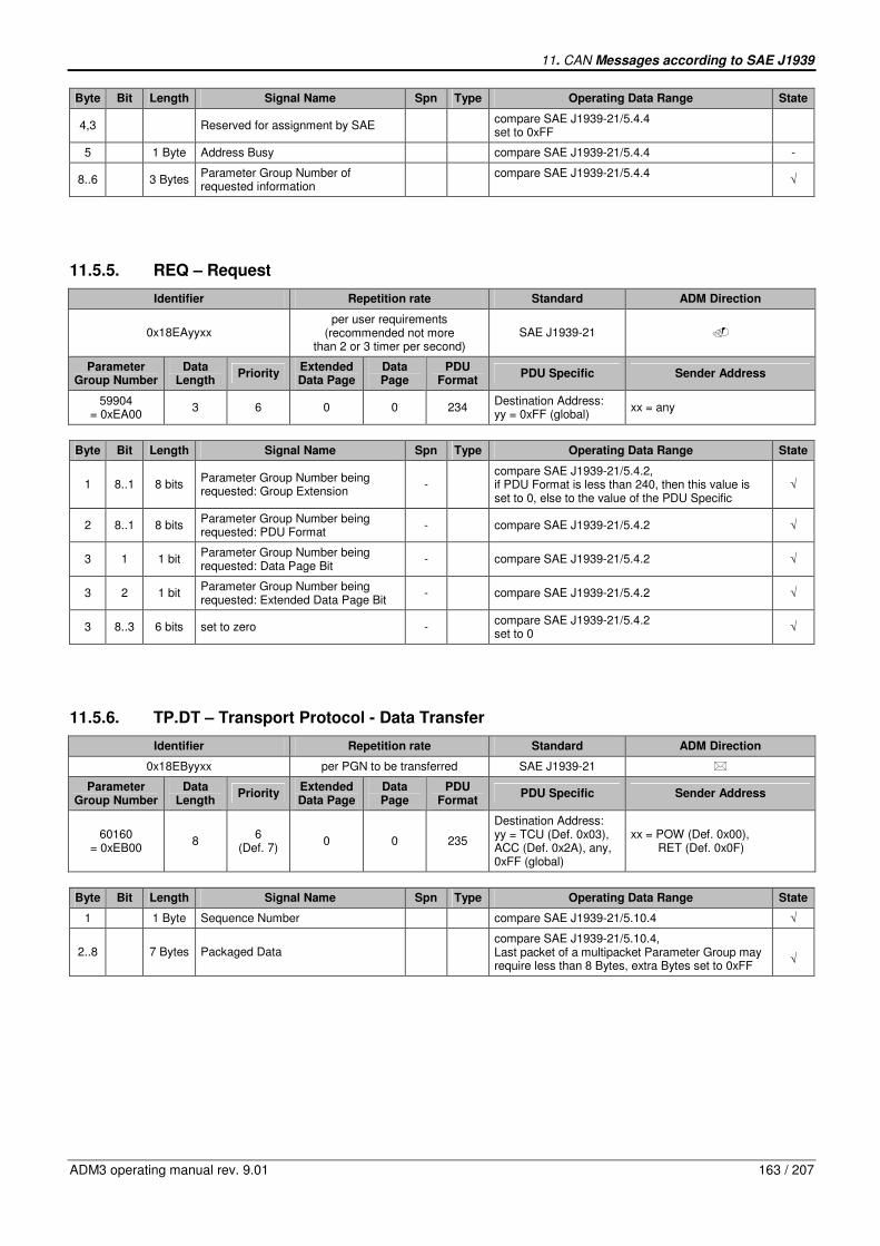
11. CAN Messages according to SAE J1939
ADM3 operating manual rev. 9.01 163 / 207
Byte Bit Length Signal Name Spn Type Operating Data Range State
4,3 Reserved for assignment by SAE compare SAE J1939-21/5.4.4 set to 0xFF
5 1 Byte Address Busy compare SAE J1939-21/5.4.4 -
8..6 3 Bytes Parameter Group Number of requested information
compare SAE J1939-21/5.4.4
√
11.5.5. REQ – Request
Identifier Repetition rate Standard ADM Direction
0x18EAyyxx per user requirements
(recommended not more than 2 or 3 timer per second)
SAE J1939-21 �
Parameter Group Number
Data Length
Priority Extended Data Page
Data Page
PDU Format
PDU Specific Sender Address
59904 = 0xEA00
3 6 0 0 234 Destination Address: yy = 0xFF (global)
xx = any
Byte Bit Length Signal Name Spn Type Operating Data Range State
1 8..1 8 bits Parameter Group Number being requested: Group Extension
- compare SAE J1939-21/5.4.2, if PDU Format is less than 240, then this value is set to 0, else to the value of the PDU Specific
√
2 8..1 8 bits Parameter Group Number being requested: PDU Format
- compare SAE J1939-21/5.4.2 √
3 1 1 bit Parameter Group Number being requested: Data Page Bit
- compare SAE J1939-21/5.4.2 √
3 2 1 bit Parameter Group Number being requested: Extended Data Page Bit
- compare SAE J1939-21/5.4.2 √
3 8..3 6 bits set to zero - compare SAE J1939-21/5.4.2 set to 0
√
11.5.6. TP.DT – Transport Protocol - Data Transfer
Identifier Repetition rate Standard ADM Direction
0x18EByyxx per PGN to be transferred SAE J1939-21 �
Parameter Group Number
Data Length
Priority Extended Data Page
Data Page
PDU Format
PDU Specific Sender Address
60160 = 0xEB00
8 6
(Def. 7) 0 0 235
Destination Address: yy = TCU (Def. 0x03), ACC (Def. 0x2A), any, 0xFF (global)
xx = POW (Def. 0x00), RET (Def. 0x0F)
Byte Bit Length Signal Name Spn Type Operating Data Range State
1 1 Byte Sequence Number compare SAE J1939-21/5.10.4 √
2..8 7 Bytes Packaged Data compare SAE J1939-21/5.10.4, Last packet of a multipacket Parameter Group may require less than 8 Bytes, extra Bytes set to 0xFF
√
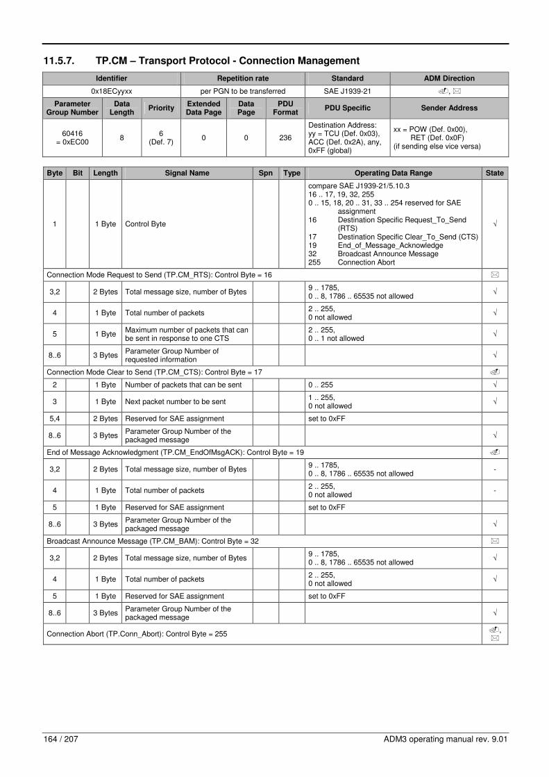
164 / 207 ADM3 operating manual rev. 9.01
11.5.7. TP.CM – Transport Protocol - Connection Management
Identifier Repetition rate Standard ADM Direction
0x18ECyyxx per PGN to be transferred SAE J1939-21 �, �
Parameter Group Number
Data Length
Priority Extended Data Page
Data Page
PDU Format
PDU Specific Sender Address
60416 = 0xEC00
8 6
(Def. 7) 0 0 236
Destination Address: yy = TCU (Def. 0x03), ACC (Def. 0x2A), any, 0xFF (global)
xx = POW (Def. 0x00), RET (Def. 0x0F) (if sending else vice versa)
Byte Bit Length Signal Name Spn Type Operating Data Range State
1 1 Byte Control Byte
compare SAE J1939-21/5.10.3 16 .. 17, 19, 32, 255 0 .. 15, 18, 20 .. 31, 33 .. 254 reserved for SAE assignment 16 Destination Specific Request_To_Send (RTS) 17 Destination Specific Clear_To_Send (CTS) 19 End_of_Message_Acknowledge 32 Broadcast Announce Message 255 Connection Abort
√
Connection Mode Request to Send (TP.CM_RTS): Control Byte = 16 �
3,2 2 Bytes Total message size, number of Bytes 9 .. 1785, 0 .. 8, 1786 .. 65535 not allowed
√
4 1 Byte Total number of packets 2 .. 255, 0 not allowed
√
5 1 Byte Maximum number of packets that can be sent in response to one CTS
2 .. 255, 0 .. 1 not allowed
√
8..6 3 Bytes Parameter Group Number of requested information
√
Connection Mode Clear to Send (TP.CM_CTS): Control Byte = 17 �
2 1 Byte Number of packets that can be sent 0 .. 255 √
3 1 Byte Next packet number to be sent 1 .. 255, 0 not allowed
√
5,4 2 Bytes Reserved for SAE assignment set to 0xFF
8..6 3 Bytes Parameter Group Number of the packaged message
√
End of Message Acknowledgment (TP.CM_EndOfMsgACK): Control Byte = 19 �
3,2 2 Bytes Total message size, number of Bytes 9 .. 1785, 0 .. 8, 1786 .. 65535 not allowed
-
4 1 Byte Total number of packets 2 .. 255, 0 not allowed
-
5 1 Byte Reserved for SAE assignment set to 0xFF
8..6 3 Bytes Parameter Group Number of the packaged message
√
Broadcast Announce Message (TP.CM_BAM): Control Byte = 32 �
3,2 2 Bytes Total message size, number of Bytes 9 .. 1785, 0 .. 8, 1786 .. 65535 not allowed
√
4 1 Byte Total number of packets 2 .. 255, 0 not allowed
√
5 1 Byte Reserved for SAE assignment set to 0xFF
8..6 3 Bytes Parameter Group Number of the packaged message
√
Connection Abort (TP.Conn_Abort): Control Byte = 255 �, �

11. CAN Messages according to SAE J1939
ADM3 operating manual rev. 9.01 165 / 207
Byte Bit Length Signal Name Spn Type Operating Data Range State
2 1 Byte Connection Abort reason
1 .. 255, 1 Already in one or more connection managed sessions and cannot support another 2 System resources were needed for another task so this connection managed session was terminated 3 A timeout occurred and this is the connection abort to close the session 4 .. 250 Reserved for SAE assignment 251 .. 255 Per J1939-71 definitions
-
5..3 3 Bytes Reserved for SAE assignment set to 0xFF
8..6 3 Bytes Parameter Group Number of the packaged message
√
11.5.8. ACL – Address Claimed/Cannot Claim
Identifier Repetition rate Standard ADM Direction
0x18EEFFxx as required SAE J1939-81 �, �
Parameter Group Number
Data Length
Priority Extended Data Page
Data Page
PDU Format
PDU Specific Sender Address
60928 = 0xEE00
8 6 0 0 238 255 (global address) (if sending else vice versa)
xx = POW (Def. 0x00), RET (Def. 0x0F), 0xFE (cannot claim)
Byte Bit Length Signal Name Spn Type Operating Data Range State
3, 2, 1
5..1 8..1 8..1
21 bits Identity Number - compare SAE 1939-81/4.2.2 and 4.1.1 √
4, 3
8..1 8..6
11 bits Manufacturer Code - compare SAE 1939-81/4.2.2 and 4.1.1 √
5 3..1 3 bits ECU Instance - compare SAE 1939-81/4.2.2 and 4.1.1 √
5 8..4 5 bits Function Instance - compare SAE 1939-81/4.2.2 and 4.1.1 √
6 8..1 8 bits Function - compare SAE 1939-81/4.2.2 and 4.1.1 √
7 1 Reserved - compare SAE 1939-81/4.2.2 and 4.1.1 should be set to 0
√
7 8..2 7 bits Vehicle System - compare SAE 1939-81/4.2.2 and 4.1.1 √
8 4..1 4 bits Vehicle System Instance - compare SAE 1939-81/4.2.2 and 4.1.1 √
8 7..5 3 bits Industry Group - compare SAE 1939-81/4.2.2 and 4.1.1 √
8 8 1 bit Arbitrary Address Capable -
compare SAE 1939-81/4.2.2 and 4.1.1 0b .. 1b 1b ECU is capable to resolve address conflict with an ECU whose NAME has a higher priority
√
11.5.9. ESS – Proprietary A (Engine Start/Stop)
Identifier Repetition rate Standard ADM Direction
0x0CEFyyxx 50ms SAE J1939-21 �
Parameter Group Number
Data Length
Priority Extended Data Page
Data Page
PDU Format
PDU Specific Sender Address
61184 = 0xEF00
8 3
(Def. 6) 0 0 239
Destination Address: yy = POW (Def. 0x00)
xx = TCU (Def. 0x03), ABU (Def. 0x0B), ADR3 (Def. 0x1E)

166 / 207 ADM3 operating manual rev. 9.01
Byte Bit Length Signal Name Spn Type Operating Data Range State
1 2,1 2 bits Engine Start/Stop Inhibit Fuel Injection
- S
00b .. 11b, 4 states/2bit, 0 offset 00b Do not inhibit Fuel Injection 01b Inhibit Fuel Injection 10b Not defined 11b Signal not available
√
1 4,3 2 bits Engine Start/Stop Engine Start - S
00b .. 11b, 4 states/2bit, 0 offset 00b No Engine Start 01b Engine Start 10b Not defined 11b Signal not available
√
1 6,5 2 bits Engine Start/Stop Inhibit Engine Start - S
00b .. 11b, 4 states/2bit, 0 offset 00b Do not inhibit Engine Start 01b Inhibit Engine Start 10b Not defined 11b Signal not available
√
1 8,7 Not defined
2 2,1 2 bits Engine Start/Stop Engine Shut Down Override
- S
00b .. 11b, 4 states/2bit, 0 offset 00b Highest priority 01b Engine Shut down override 10b Not defined 11b Signal not available
√
2 8..3 Not defined
8..3 Not defined
11.5.10. KWP – Proprietary A from Minidiag
Identifier Repetition rate Standard ADM Direction
0x0CEFyyxx request SAE J1939-21 �
Parameter Group Number
Data Length
Priority Extended Data Page
Data Page
PDU Format
PDU Specific Sender Address
61184 = 0xEF00
8 3
(Def. 6) 0 0 239
Destination Address: yy = POW (Def. 0x00)
xx = 0xF1 (Minidiag)
Byte Bit Length Signal Name Spn Type Operating Data Range State
1 1 Byte Destination Identifier - S
0 .. 255, 35 To Vehicle Control Unit 168 To Transmission Control Unit else Default
√
2 1 Byte Instruction - S
0x00 .. 0xFF, 0x14 Delete Error Memory 0x21 Read Memory 0x22 Read Data 0x23 Read Random Access Memory 0x27 Access Permission 0x2E Write Data or Change of Parameter in Service Mode 0x31 Start Routines 0x34 Download Init 0x35 Upload Init 0x36 Up/Down Transfer 0x37 Up/Down End 0x3B Write Access Date 0x3E Tester present, Prevention of Timeout 0xA1 Read Error Memory one by one 0xAB Write Parameter Groups 0xAE Reset Parameters to Default values 0x81 Write Instruction to Buffer 0x82 Write Instruction to Buffer else Request not supported
√
8..3 6 Bytes Data - 0x00 .. 0xFF for each Byte √
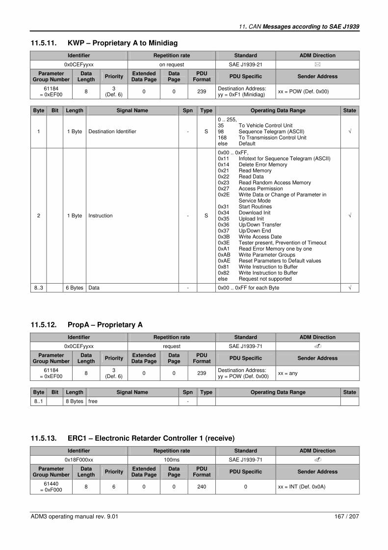
11. CAN Messages according to SAE J1939
ADM3 operating manual rev. 9.01 167 / 207
11.5.11. KWP – Proprietary A to Minidiag
Identifier Repetition rate Standard ADM Direction
0x0CEFyyxx on request SAE J1939-21 �
Parameter Group Number
Data Length
Priority Extended Data Page
Data Page
PDU Format
PDU Specific Sender Address
61184 = 0xEF00
8 3
(Def. 6) 0 0 239
Destination Address: yy = 0xF1 (Minidiag)
xx = POW (Def. 0x00)
Byte Bit Length Signal Name Spn Type Operating Data Range State
1 1 Byte Destination Identifier - S
0 .. 255, 35 To Vehicle Control Unit 98 Sequence Telegram (ASCII) 168 To Transmission Control Unit else Default
√
2 1 Byte Instruction - S
0x00 .. 0xFF, 0x11 Infotext for Sequence Telegram (ASCII) 0x14 Delete Error Memory 0x21 Read Memory 0x22 Read Data 0x23 Read Random Access Memory 0x27 Access Permission 0x2E Write Data or Change of Parameter in Service Mode 0x31 Start Routines 0x34 Download Init 0x35 Upload Init 0x36 Up/Down Transfer 0x37 Up/Down End 0x3B Write Access Date 0x3E Tester present, Prevention of Timeout 0xA1 Read Error Memory one by one 0xAB Write Parameter Groups 0xAE Reset Parameters to Default values 0x81 Write Instruction to Buffer 0x82 Write Instruction to Buffer else Request not supported
√
8..3 6 Bytes Data - 0x00 .. 0xFF for each Byte √
11.5.12. PropA – Proprietary A
Identifier Repetition rate Standard ADM Direction
0x0CEFyyxx request SAE J1939-71 �
Parameter Group Number
Data Length
Priority Extended Data Page
Data Page
PDU Format
PDU Specific Sender Address
61184 = 0xEF00
8 3
(Def. 6) 0 0 239
Destination Address: yy = POW (Def. 0x00)
xx = any
Byte Bit Length Signal Name Spn Type Operating Data Range State
8..1 8 Bytes free -
11.5.13. ERC1 – Electronic Retarder Controller 1 (receive)
Identifier Repetition rate Standard ADM Direction
0x18F000xx 100ms SAE J1939-71 �
Parameter Group Number
Data Length
Priority Extended Data Page
Data Page
PDU Format
PDU Specific Sender Address
61440 = 0xF000
8 6 0 0 240 0 xx = INT (Def. 0x0A)
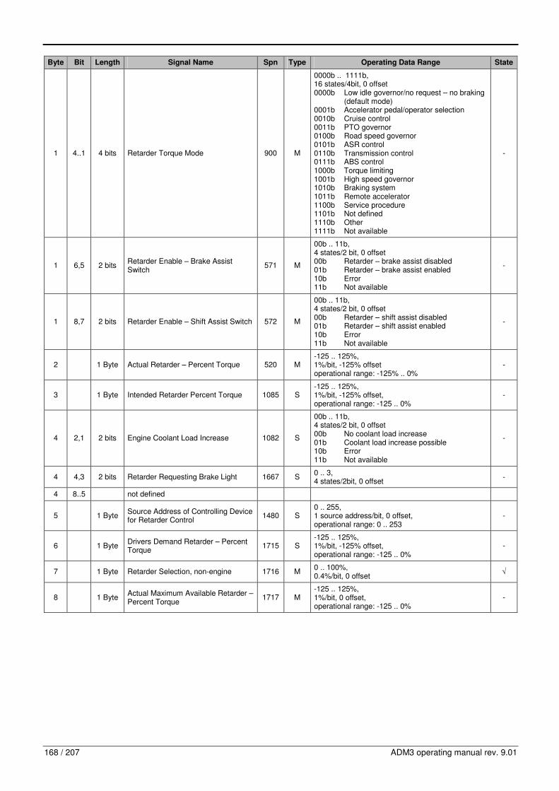
168 / 207 ADM3 operating manual rev. 9.01
Byte Bit Length Signal Name Spn Type Operating Data Range State
1 4..1 4 bits Retarder Torque Mode 900 M
0000b .. 1111b, 16 states/4bit, 0 offset 0000b Low idle governor/no request – no braking (default mode) 0001b Accelerator pedal/operator selection 0010b Cruise control 0011b PTO governor 0100b Road speed governor 0101b ASR control 0110b Transmission control 0111b ABS control 1000b Torque limiting 1001b High speed governor 1010b Braking system 1011b Remote accelerator 1100b Service procedure 1101b Not defined 1110b Other 1111b Not available
-
1 6,5 2 bits Retarder Enable – Brake Assist Switch
571 M
00b .. 11b, 4 states/2 bit, 0 offset 00b Retarder – brake assist disabled 01b Retarder – brake assist enabled 10b Error 11b Not available
-
1 8,7 2 bits Retarder Enable – Shift Assist Switch 572 M
00b .. 11b, 4 states/2 bit, 0 offset 00b Retarder – shift assist disabled 01b Retarder – shift assist enabled 10b Error 11b Not available
-
2 1 Byte Actual Retarder – Percent Torque 520 M -125 .. 125%, 1%/bit, -125% offset operational range: -125% .. 0%
-
3 1 Byte Intended Retarder Percent Torque 1085 S -125 .. 125%, 1%/bit, -125% offset, operational range: -125 .. 0%
-
4 2,1 2 bits Engine Coolant Load Increase 1082 S
00b .. 11b, 4 states/2 bit, 0 offset 00b No coolant load increase 01b Coolant load increase possible 10b Error 11b Not available
-
4 4,3 2 bits Retarder Requesting Brake Light 1667 S 0 .. 3, 4 states/2bit, 0 offset
-
4 8..5 not defined
5 1 Byte Source Address of Controlling Device for Retarder Control
1480 S 0 .. 255, 1 source address/bit, 0 offset, operational range: 0 .. 253
-
6 1 Byte Drivers Demand Retarder – Percent Torque
1715 S -125 .. 125%, 1%/bit, -125% offset, operational range: -125 .. 0%
-
7 1 Byte Retarder Selection, non-engine 1716 M 0 .. 100%, 0.4%/bit, 0 offset
√
8 1 Byte Actual Maximum Available Retarder – Percent Torque
1717 M -125 .. 125%, 1%/bit, 0 offset, operational range: -125 .. 0%
-

11. CAN Messages according to SAE J1939
ADM3 operating manual rev. 9.01 169 / 207
11.5.14. ERC1 – Electronic Retarder Controller 1 (send)
Identifier Repetition rate Standard ADM Direction
0x18F000xx 100ms SAE J1939-71 �
Parameter Group Number
Data Length
Priority Extended Data Page
Data Page
PDU Format
PDU Specific Sender Address
61440 = 0xF000
8 6 0 0 240 0 xx = RET (Def. 0x0F)
Byte Bit Length Signal Name Spn Type Operating Data Range State
1 4..1 4 bits Retarder Torque Mode 900 M
0000b .. 1111b, 16 states/4bit, 0 offset 0000b Low idle governor/no request – no braking (default mode) 0001b Accelerator pedal/operator selection 0010b Cruise control 0011b PTO governor 0100b Road speed governor 0101b ASR control 0110b Transmission control 0111b ABS control 1000b Torque limiting 1001b High speed governor 1010b Braking system 1011b Remote accelerator 1100b Service procedure 1101b Not defined 1110b Other 1111b Not available
√
1 6,5 2 bits Retarder Enable – Brake Assist Switch
571 M
00b .. 11b, 4 states/2 bit, 0 offset 00b Retarder – brake assist disabled 01b Retarder – brake assist enabled 10b Error 11b Not available
√
1 8,7 2 bits Retarder Enable – Shift Assist Switch 572 M
00b .. 11b, 4 states/2 bit, 0 offset 00b Retarder – shift assist disabled 01b Retarder – shift assist enabled 10b Error 11b Not available
√
2 1 Byte Actual Retarder – Percent Torque 520 M -125 .. 125%, 1%/bit, -125% offset operational range: -125% .. 0%
√
3 1 Byte Intended Retarder Percent Torque 1085 S -125 .. 125%, 1%/bit, -125% offset, operational range: -125 .. 0%
-
4 2,1 2 bits Engine Coolant Load Increase 1082 S
00b .. 11b, 4 states/2 bit, 0 offset 00b No coolant load increase 01b Coolant load increase possible 10b Error 11b Not available
-
4 4,3 2 bits Retarder Requesting Brake Light 1667 S 0 .. 3, 4 states/2bit, 0 offset
-
4 8..5 not defined
5 1 Byte Source Address of Controlling Device for Retarder Control
1480 S 0 .. 255, 1 source address/bit, 0 offset, operational range: 0 .. 253
√
6 1 Byte Drivers Demand Retarder – Percent Torque
1715 S -125 .. 125%, 1%/bit, -125% offset, operational range: -125 .. 0%
-
7 1 Byte Retarder Selection, non-engine 1716 M 0 .. 100%, 0.4%/bit, 0 offset
-
8 1 Byte Actual Maximum Available Retarder – Percent Torque
1717 M -125 .. 125%, 1%/bit, 0 offset, operational range: -125 .. 0%
-

170 / 207 ADM3 operating manual rev. 9.01
11.5.15. EBC1 – Electronic Brake Controller 1 (receive)
Identifier Repetition rate Standard ADM Direction
0x18F001xx 100ms SAE J1939-71 �
Parameter Group Number
Data Length
Priority Extended Data Page
Data Page
PDU Format
PDU Specific Sender Address
61441 = 0xF001
8 6 0 0 240 1 xx = EBC (Def. 0x21)
Byte Bit Length Signal Name Spn Type Operating Data Range State
1 2,1 2 bits ASR Engine Control Active 561 S
00b .. 11b, 4 states/2 bit, 0 offset, 00 ASR engine control passive but installed 01 ASR engine control active 10 Reserved 11 Not available
-
1 4,3 2 bits ASR Brake Control Active 562 S
00b .. 11b, 4 states/2 bit, 0 offset, 00 ASR brake control passive but installed 01 ASR brake control active 10 Reserved 11 Not available
-
1 6,5 2 bits Anti-Lock Braking (ABS) Active 563 S
00b .. 11b, 4 states/2 bit, 0 offset, 00 ABS passive but installed 01 ABS active 10 Reserved 11 Not available
-
1 8,7 2 bits EBS Brake Switch 1121 M
00b .. 11b, 4 states/2 bit, 0 offset, 00 Brake pedal is not being pressed 01 Brake pedal is being pressed 10 Error 11 Not available
-
2 1 Byte Brake Pedal Position 521 M 0 .. 100%, 0.4%/bit, 0 offset
-
3 2,1 2 bits ABS Off-road Switch 575 M
00b .. 11b, 4 states/2 bit, 0 offset, 00 ABS off-road switch passive 01 ABS off-road switch active 10 Error 11 Not available
-
3 4,3 2 bits ASR Off-road Switch 576 M
00b .. 11b, 4 states/2 bit, 0 offset, 00 ASR off-road switch passive 01 ASR off-road switch active 10 Error 11 Not available
-
3 6,5 2 bits ASR “Hill Holder” Switch 577 M
00b .. 11b, 4 states/2 bit, 0 offset, 00 ASR “hill holder” switch passive 01 ASR “hill holder” switch active 10 Error 11 Not available
-
3 8,7 2 bits Traction Control Override Switch 1238 M
00b .. 11b, 4 states/2 bit, 0 offset, 00 Off 01 On 10 Error 11 Not available or not installed
-
4 2,1 2 bits Accelerator Interlock Switch 972 M
00b .. 11b, 4 states/2 bit, 0 offset, 00 Off 01 On 10 Error 11 Not available
-

11. CAN Messages according to SAE J1939
ADM3 operating manual rev. 9.01 171 / 207
Byte Bit Length Signal Name Spn Type Operating Data Range State
4 4,3 2 bits Engine Derate Switch 971 M
00b .. 11b, 4 states/2 bit, 0 offset, 00 Off 01 On 10 Error 11 Not available
-
4 6,5 2 bits Engine Auxiliary Shutdown Switch 970 M
00b .. 11b, 4 states/2 bit, 0 offset, 00 Off 01 On 10 Error 11 Not available
-
4 8,7 2 bits Remote Accelerator Enable Switch 969 M
00b .. 11b, 4 states/2 bit, 0 offset, 00 Off 01 On 10 Error 11 Not available
-
5 1 Byte Engine Retarder Selection 973 M 0 .. 100%, 0.4%/bit, 0 offset
√
6 2,1 2 bits ABS Fully Operational 1243 S
00b .. 11b, 4 states/2 bit, 0 offset, 00 Not Fully Operational 01 Fully Operational 10 Reserved 11 Not available
-
6 4,3 2 bits EBS Red Warning Signal 1439 S
00b .. 11b, 4 states/2 bit, 0 offset, 00 Off 01 On 10 Reserved 11 Take no action
-
6 6,5 2 bits ABS/EBS Amber Warning Signal (Powered Vehicle)
1438 S
00b .. 11b, 4 states/2 bit, 0 offset, 00 Off 01 On 10 Reserved 11 Take no action
-
6 8,7 2 bits ATC/ASR Information Signal 1793 S
00b .. 11b, 4 states/2 bit, 0 offset, 00 Off 01 On 10 Reserved 11 Take no action
-
7 1 Byte Source Address of Controlling Device for Brake Control
1481 S 0 .. 255, 1 source address/bit, 0 offset, operational range: 0 .. 253
-
8 2,1 not defined
8 4,3 2 bits Halt Brake Switch 2911 M
00b .. 11b, 4 states/2 bit, 0 offset, 00 Halt brake switch passive 01 Halt brake switch active 10 Error 11 Not available
-
8 6,5 2 bits Trailer ABS Status 1836 S
00b .. 11b, 4 states/2 bit, 0 offset, 00 Trailer ABS Status Information Available But Not Active 01 Trailer ABS Active 10 Reserved 11 Trailer ABS Status Information Not Available or Parameter Not Supported
-
8 8,7 2 bits Tractor-Mounted Trailer ABS Warning Signal
1792 S
00b .. 11b, 4 states/2 bit, 0 offset, 00 Off 01 On 10 Reserved 11 Take no action
-

172 / 207 ADM3 operating manual rev. 9.01
11.5.16. EBC1 – Electronic Brake Controller 1 (send)
Identifier Repetition rate Standard ADM Direction
0x18F001xx 100ms SAE J1939-71 �
Parameter Group Number
Data Length
Priority Extended Data Page
Data Page
PDU Format
PDU Specific Sender Address
61441 = 0xF001
8 6 0 0 240 1 xx = POW (Def. 0x00)
Byte Bit Length Signal Name Spn Type Operating Data Range State
1 2,1 2 bits ASR Engine Control Active 561 S
00b .. 11b, 4 states/2 bit, 0 offset, 00 ASR engine control passive but installed 01 ASR engine control active 10 Reserved 11 Not available
-
1 4,3 2 bits ASR Brake Control Active 562 S
00b .. 11b, 4 states/2 bit, 0 offset, 00 ASR brake control passive but installed 01 ASR brake control active 10 Reserved 11 Not available
-
1 6,5 2 bits Anti-Lock Braking (ABS) Active 563 S
00b .. 11b, 4 states/2 bit, 0 offset, 00 ABS passive but installed 01 ABS active 10 Reserved 11 Not available
√
1 8,7 2 bits EBS Brake Switch 1121 M
00b .. 11b, 4 states/2 bit, 0 offset, 00 Brake pedal is not being pressed 01 Brake pedal is being pressed 10 Error 11 Not available
-
2 1 Byte Brake Pedal Position 521 M 0 .. 100%, 0.4%/bit, 0 offset
-
3 2,1 2 bits ABS Off-road Switch 575 M
00b .. 11b, 4 states/2 bit, 0 offset, 00 ABS off-road switch passive 01 ABS off-road switch active 10 Error 11 Not available
-
3 4,3 2 bits ASR Off-road Switch 576 M
00b .. 11b, 4 states/2 bit, 0 offset, 00 ASR off-road switch passive 01 ASR off-road switch active 10 Error 11 Not available
-
3 6,5 2 bits ASR “Hill Holder” Switch 577 M
00b .. 11b, 4 states/2 bit, 0 offset, 00 ASR “hill holder” switch passive 01 ASR “hill holder” switch active 10 Error 11 Not available
-
3 8,7 2 bits Traction Control Override Switch 1238 M
00b .. 11b, 4 states/2 bit, 0 offset, 00 Off 01 On 10 Error 11 Not available or not installed
-
4 2,1 2 bits Accelerator Interlock Switch 972 M
00b .. 11b, 4 states/2 bit, 0 offset, 00 Off 01 On 10 Error 11 Not available
-
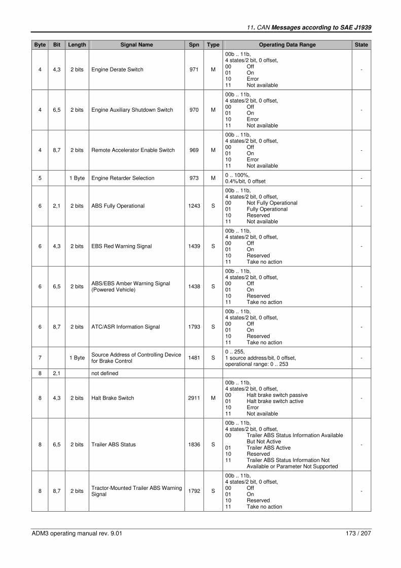
11. CAN Messages according to SAE J1939
ADM3 operating manual rev. 9.01 173 / 207
Byte Bit Length Signal Name Spn Type Operating Data Range State
4 4,3 2 bits Engine Derate Switch 971 M
00b .. 11b, 4 states/2 bit, 0 offset, 00 Off 01 On 10 Error 11 Not available
-
4 6,5 2 bits Engine Auxiliary Shutdown Switch 970 M
00b .. 11b, 4 states/2 bit, 0 offset, 00 Off 01 On 10 Error 11 Not available
-
4 8,7 2 bits Remote Accelerator Enable Switch 969 M
00b .. 11b, 4 states/2 bit, 0 offset, 00 Off 01 On 10 Error 11 Not available
-
5 1 Byte Engine Retarder Selection 973 M 0 .. 100%, 0.4%/bit, 0 offset
-
6 2,1 2 bits ABS Fully Operational 1243 S
00b .. 11b, 4 states/2 bit, 0 offset, 00 Not Fully Operational 01 Fully Operational 10 Reserved 11 Not available
-
6 4,3 2 bits EBS Red Warning Signal 1439 S
00b .. 11b, 4 states/2 bit, 0 offset, 00 Off 01 On 10 Reserved 11 Take no action
-
6 6,5 2 bits ABS/EBS Amber Warning Signal (Powered Vehicle)
1438 S
00b .. 11b, 4 states/2 bit, 0 offset, 00 Off 01 On 10 Reserved 11 Take no action
-
6 8,7 2 bits ATC/ASR Information Signal 1793 S
00b .. 11b, 4 states/2 bit, 0 offset, 00 Off 01 On 10 Reserved 11 Take no action
-
7 1 Byte Source Address of Controlling Device for Brake Control
1481 S 0 .. 255, 1 source address/bit, 0 offset, operational range: 0 .. 253
-
8 2,1 not defined
8 4,3 2 bits Halt Brake Switch 2911 M
00b .. 11b, 4 states/2 bit, 0 offset, 00 Halt brake switch passive 01 Halt brake switch active 10 Error 11 Not available
-
8 6,5 2 bits Trailer ABS Status 1836 S
00b .. 11b, 4 states/2 bit, 0 offset, 00 Trailer ABS Status Information Available But Not Active 01 Trailer ABS Active 10 Reserved 11 Trailer ABS Status Information Not Available or Parameter Not Supported
-
8 8,7 2 bits Tractor-Mounted Trailer ABS Warning Signal
1792 S
00b .. 11b, 4 states/2 bit, 0 offset, 00 Off 01 On 10 Reserved 11 Take no action
-
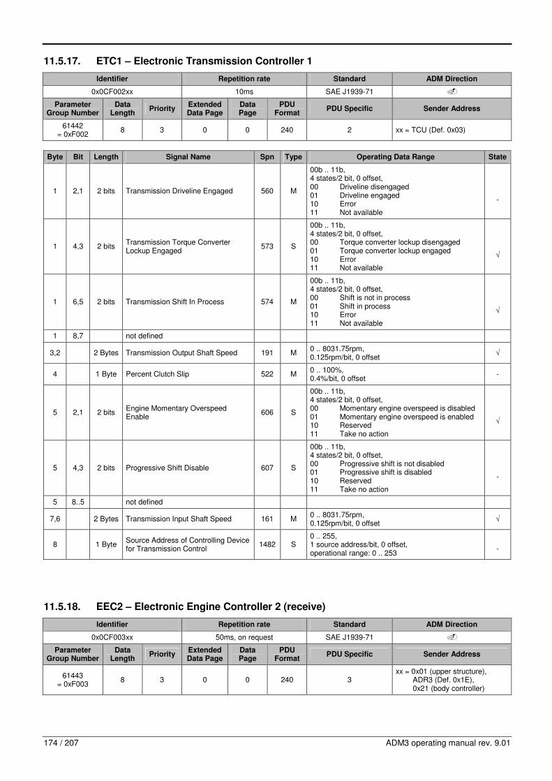
174 / 207 ADM3 operating manual rev. 9.01
11.5.17. ETC1 – Electronic Transmission Controller 1
Identifier Repetition rate Standard ADM Direction
0x0CF002xx 10ms SAE J1939-71 �
Parameter Group Number
Data Length
Priority Extended Data Page
Data Page
PDU Format
PDU Specific Sender Address
61442 = 0xF002
8 3 0 0 240 2 xx = TCU (Def. 0x03)
Byte Bit Length Signal Name Spn Type Operating Data Range State
1 2,1 2 bits Transmission Driveline Engaged 560 M
00b .. 11b, 4 states/2 bit, 0 offset, 00 Driveline disengaged 01 Driveline engaged 10 Error 11 Not available
-
1 4,3 2 bits Transmission Torque Converter Lockup Engaged
573 S
00b .. 11b, 4 states/2 bit, 0 offset, 00 Torque converter lockup disengaged 01 Torque converter lockup engaged 10 Error 11 Not available
√
1 6,5 2 bits Transmission Shift In Process 574 M
00b .. 11b, 4 states/2 bit, 0 offset, 00 Shift is not in process 01 Shift in process 10 Error 11 Not available
√
1 8,7 not defined
3,2 2 Bytes Transmission Output Shaft Speed 191 M 0 .. 8031.75rpm, 0.125rpm/bit, 0 offset
√
4 1 Byte Percent Clutch Slip 522 M 0 .. 100%, 0.4%/bit, 0 offset
-
5 2,1 2 bits Engine Momentary Overspeed Enable
606 S
00b .. 11b, 4 states/2 bit, 0 offset, 00 Momentary engine overspeed is disabled 01 Momentary engine overspeed is enabled 10 Reserved 11 Take no action
√
5 4,3 2 bits Progressive Shift Disable 607 S
00b .. 11b, 4 states/2 bit, 0 offset, 00 Progressive shift is not disabled 01 Progressive shift is disabled 10 Reserved 11 Take no action
-
5 8..5 not defined
7,6 2 Bytes Transmission Input Shaft Speed 161 M 0 .. 8031.75rpm, 0.125rpm/bit, 0 offset
√
8 1 Byte Source Address of Controlling Device for Transmission Control
1482 S 0 .. 255, 1 source address/bit, 0 offset, operational range: 0 .. 253
-
11.5.18. EEC2 – Electronic Engine Controller 2 (receive)
Identifier Repetition rate Standard ADM Direction
0x0CF003xx 50ms, on request SAE J1939-71 �
Parameter Group Number
Data Length
Priority Extended Data Page
Data Page
PDU Format
PDU Specific Sender Address
61443 = 0xF003
8 3 0 0 240 3 xx = 0x01 (upper structure), ADR3 (Def. 0x1E), 0x21 (body controller)

11. CAN Messages according to SAE J1939
ADM3 operating manual rev. 9.01 175 / 207
Byte Bit Length Signal Name Spn Type Operating Data Range State
1 2,1 2 bits Accelerator Pedal 1 Low Switch 558 M
00b .. 11b, 4 states/2 bit, 0 offset, 00 Accelerator pedal 1 not in low idle condition 01 Accelerator pedal 1 in low idle condition 10 Error 11 Not available
√
1 4,3 2 bits Accelerator Pedal Kickdown Switch 559 M
00b .. 11b, 4 states/2 bit, 0 offset, 00 Kickdown passive 01 Kickdown active 10 Error 11 Not available
√
1 6,5 2 bits Road Speed Limit Status 1437 S
00b .. 11b, 4 states/2 bit, 0 offset, 00 Active 01 Not Active 10 Error 11 Not available
-
1 8,7 2 bits Accelerator Pedal 2 Low Idle Switch 2970 M
00b .. 11b, 4 states/2 bit, 0 offset, 00 Accelerator pedal 2 not in low idle condition 01 Accelerator pedal 2 in low idle condition 10 Error 11 Not available
-
2 1 Byte Accelerator Pedal Position 1 91 M 0 .. 100%, 0.4%/bit, 0 offset
√
3 1 Byte Engine Percent Load At Current Speed
92 S 0 .. 250%, 1%/bit, 0 offset, operational range: 0 .. 125%
-
4 1 Byte Remote Accelerator Pedal Position 974 M 0 .. 100%, 0.4%/bit, 0 offset
-
5 1 Byte Accelerator Pedal Position 2 29 M 0 .. 100%, 0.4%/bit, 0 offset
-
6 2,1 2 bits Vehicle Acceleration Rate Limit Status
2979 S
00b .. 11b, 4 states/2 bit, 0 offset, 00 Limit not active 01 Limit active 10 Reserved 11 Not available
-
6 8..3 not defined
7 1 Byte Actual Maximum Available Engine – Percent Torque
3357 M 0 .. 100%, 0.4%/bit, 0 offset
-
8 not defined
11.5.19. EEC2 – Electronic Engine Controller 2 (send)
Identifier Repetition rate Standard ADM Direction
0x0CF003xx 50ms, on request SAE J1939-71 �
Parameter Group Number
Data Length
Priority Extended Data Page
Data Page
PDU Format
PDU Specific Sender Address
61443 = 0xF003
8 3 0 0 240 3 xx = POW (Def. 0x00)
Byte Bit Length Signal Name Spn Type Operating Data Range State
1 2,1 2 bits Accelerator Pedal 1 Low Switch 558 M
00b .. 11b, 4 states/2 bit, 0 offset, 00 Accelerator pedal 1 not in low idle condition 01 Accelerator pedal 1 in low idle condition 10 Error 11 Not available
√

176 / 207 ADM3 operating manual rev. 9.01
Byte Bit Length Signal Name Spn Type Operating Data Range State
1 4,3 2 bits Accelerator Pedal Kickdown Switch 559 M
00b .. 11b, 4 states/2 bit, 0 offset, 00 Kickdown passive 01 Kickdown active 10 Error 11 Not available
√
1 6,5 2 bits Road Speed Limit Status 1437 S
00b .. 11b, 4 states/2 bit, 0 offset, 00 Active 01 Not Active 10 Error 11 Not available
√
1 8,7 2 bits Accelerator Pedal 2 Low Idle Switch 2970 M
00b .. 11b, 4 states/2 bit, 0 offset, 00 Accelerator pedal 2 not in low idle condition 01 Accelerator pedal 2 in low idle condition 10 Error 11 Not available
-
2 1 Byte Accelerator Pedal Position 1 91 M 0 .. 100%, 0.4%/bit, 0 offset
√
3 1 Byte Engine Percent Load At Current Speed
92 S 0 .. 250%, 1%/bit, 0 offset, operational range: 0 .. 125%
√
4 1 Byte Remote Accelerator Pedal Position 974 M 0 .. 100%, 0.4%/bit, 0 offset
-
5 1 Byte Accelerator Pedal Position 2 29 M 0 .. 100%, 0.4%/bit, 0 offset
-
6 2,1 2 bits Vehicle Acceleration Rate Limit Status
2979 S
00b .. 11b, 4 states/2 bit, 0 offset, 00 Limit not active 01 Limit active 10 Reserved 11 Not available
√
6 8..3 not defined
7 1 Byte Actual Maximum Available Engine – Percent Torque
3357 M 0 .. 100%, 0.4%/bit, 0 offset
-
8 not defined
11.5.20. EEC1 – Electronic Engine Controller 1
Identifier Repetition rate Standard ADM Direction
0x0CF004xx 10ms, on request SAE J1939-71 �
Parameter Group Number
Data Length
Priority Extended Data Page
Data Page
PDU Format
PDU Specific Sender Address
61444 = 0xF004
8 3 0 0 240 4 xx = POW (Def. 0x00)

11. CAN Messages according to SAE J1939
ADM3 operating manual rev. 9.01 177 / 207
Byte Bit Length Signal Name Spn Type Operating Data Range State
1 4..1 4 bits Engine Torque Mode 899 M
0000b .. 1111b, 16 states/4bit, 0 offset 0000b Low idle governor/no request (default mode) 0001b Accelerator pedal/operator selection 0010b Cruise control 0011b PTO governor 0100b Road speed governor 0101b ASR control 0110b Transmission control 0111b ABS control 1000b Torque limiting 1001b High speed governor 1010b Braking system 1011b Remote accelerator 1100b Service procedure 1101b Not defined 1110b Other 1111b Not available
√
1 8..5 not defined
2 1 Byte Driver’s Demand Engine – Percent Torque
512 M -125 .. 125%, 1%/bit, -125% offset, operational range: 0 .. 125%
√
3 1 Byte Actual Engine – Percent Torque 513 M -125 .. 125%, 1%/bit, -125% offset, operational range: 0 .. 125%
√
5,4 2 Bytes Engine Speed 190 M 0 .. 8031.875rpm, 0.125rpm/bit, 0 offset
√
6 1 Byte Source Address of Controlling Device for Engine Control
1483 S 0 .. 255, 1 source address/bit,0 offset, operational range: 0 .. 253
√
7 4..1 4 bits Engine Starter mode 1675 S
0000b .. 1111b, 16 states/4bit, 0 offset 0000b Start not requested 0001b Starter active, gear not engaged 0010b Starter active, gear engaged 0011b Start finished, starter not active after having been actively engaged (after 50ms mode goes to 0000b) 0100b Starter inhibited due to engine already running 0101b Starter inhibited due to engine not ready for start (preheating) 0110b Starter inhibited due to driveline engaged or other transmission inhibit 0111b Starter inhibited due to active immobilizer 1000b Starter inhibited due to starter over-temp 1001b-1011b Reserved 1100b Starter inhibited – reason unknown 1101b Error (legacy implementation only, use 1110b) 1110b Error 1111b Not available
-
8 1 Byte Engine Demand – Percent Torque 2432 -125 .. 125%, 1%/bit, -125% offset
√
11.5.21. ETC2 – Electronic Transmission Controller 2
Identifier Repetition rate Standard ADM Direction
0x18F005xx 100ms SAE J1939-71 �
Parameter Group Number
Data Length
Priority Extended Data Page
Data Page
PDU Format
PDU Specific Sender Address
61445 = 0xF005
8 6 0 0 240 5 xx = TCU (Def. 0x03)

178 / 207 ADM3 operating manual rev. 9.01
Byte Bit Length Signal Name Spn Type Operating Data Range State
1 1 Byte Transmission Selected Gear 524 S
-125 .. 125, 1 gear value/bit, -125 offset, operational range: -125 .. 125, negative values are reverse gears, positive values are forward gears, zero is neutral, 251 (0xFB) is park
√
3,2 2 Bytes Transmission Actual Gear Ratio 526 M 0 .. 64.255, 0.001/bit, 0 offset
-
4 1 Byte Transmission Current Gear 523 M
-125 .. 125, 1 gear value/bit, -125 offset, operational range: -125 .. 125, negative values are reverse gears, positive values are forward gears, zero is neutral, 251 (0xFB) is park
√
6,5 2 Bytes Transmission Requested Range 162 S
0 .. 255 per Byte, ASCII characters, 0 offset, characters may include P, Rx, Rx-1 .. R2, R1, Nx, Nx-1 .. N2, N, D, D1, D2, .., Dx, L, L1, L2 .., Lx-1, 1, 2, 3, .., if only one character is used, the second character shall be used and the first shall be a space (ASCII 32) or a control character (ASCII 0 to 31)
-
8,7 2 Bytes Transmission Current Range 163 S
0 .. 255 per Byte, ASCII characters, 0 offset, characters may include P, Rx, Rx-1 .. R2, R1, Nx, Nx-1 .. N2, N, D, D1, D2, .., Dx, L, L1, L2 .., Lx-1, 1, 2, 3, .., if only one character is used, the second character shall be used and the first shall be a space (ASCII 32) or a control character (ASCII 0 to 31)
-
11.5.22. ETC7 – Electronic Transmission Controller 7
Identifier Repetition rate Standard ADM Direction
0x18FE4Axx 100ms SAE J1939-71 �
Parameter Group Number
Data Length
Priority Extended Data Page
Data Page
PDU Format
PDU Specific Sender Address
65098 = 0xFE4A
8 6 0 0 254 74 xx = TCU (Def. 0x03)
Byte Bit Length Signal Name Spn Type Operating Data Range State
1 4..1 Not defined
1 6,5 2 bits Transmission Requested Range Display Blank State
1850 S
00b .. 11b, 4 states/2bit, 0 offset 00b Inactive, Transmission Requested Range display should not be blanked 01b Active, Transmission Requested Range display should be blanked 10b Reserved 11b Take no action
-
1 8,7 2 bits Transmission Requested Range Display Flash State
1849 S
00b .. 11b, 4 states/2bit, 0 offset 00b Inactive, Transmission Requested Range display should not be flashing 01b Active, Transmission Requested Range display should be flashing 10b Reserved 11b Take no action
-
2 2,1 2 bits Transmission Ready for Brake Release
3086 S
00b .. 11b, 4 states/2bit, 0 offset 00b Transmission Not Ready for Brake Release 01b Transmission Ready for Brake Release 10b Reserved 11b Don’t Care
-

11. CAN Messages according to SAE J1939
ADM3 operating manual rev. 9.01 179 / 207
Byte Bit Length Signal Name Spn Type Operating Data Range State
2 4,3 2 bits Active Shift Console Indicator 2945 S
00b .. 11b, 4 states/2bit, 0 offset 00b Primary shift console is active 01b Secondary shift console is active 10b Reserved 11b Not available
-
2 6,5 2 bits Transmission Engine Crank Enable 2900 S
00b .. 11b, 4 states/2bit, 0 offset 00b Cranking disabled, engine cranking is prohibited by the transmission 01b Cranking enabled, engine cranking is allowed by the transmission 10b Error 11b Not available
√
2 8,7 2 bits Transmission Shift Inhibit Indicator 1851 S
00b .. 11b, 4 states/2bit, 0 offset 00b Inactive, shift is not inhibited 01b Active, shift is inhibited 10b Reserved 11b Take no action
-
3 2,1 2 bits Transmission Mode 4 Indicator 2539 S
00b .. 11b, 4 states/2bit, 0 offset 00b Transmission Mode 4 not active 01b Transmission Mode 4 active 10b Error 11b Not available
-
3 4,3 2 bits Transmission Mode 3 Indicator 2538 S
00b .. 11b, 4 states/2bit, 0 offset 00b Transmission Mode 3 not active 01b Transmission Mode 3 active 10b Error 11b Not available
-
3 6,5 2 bits Transmission Mode 2 Indicator 2537 S
00b .. 11b, 4 states/2bit, 0 offset 00b Transmission Mode 2 not active 01b Transmission Mode 2 active 10b Error 11b Not available
-
3 8,7 2 bits Transmission Mode 1 Indicator 2536 S
00b .. 11b, 4 states/2bit, 0 offset 00b Transmission Mode 1 not active 01b Transmission Mode 1 active 10b Error 11b Not available
-
4 1 Byte Transmission Requested Gear Feedback
3289 S -125 .. 125, 1 gear value/bit, -125 offset
-
8..5 Not defined
11.5.23. TI1 – Tank Information 1
Identifier Repetition rate Standard ADM Direction
0x18FE56xx 1s SAE J1939-71, SAE J1939-73
�
Parameter Group Number
Data Length
Priority Extended Data Page
Data Page
PDU Format
PDU Specific Sender Address
65110 = 0xFE56
8 6 0 0 254 86 xx = POW (Def. 0x00)
Byte Bit Length Signal Name Spn Type Operating Data Range State
1 1 Byte Catalyst Tank Level 1761 M
0 .. 100%, 0.4%/bit, 0 offset, 0% Empty 100% Full
√
2 1 Byte Catalyst Tank Temperature 3031 M -40 .. 210°C, 1°C/bit, -40°C offset
-

180 / 207 ADM3 operating manual rev. 9.01
Byte Bit Length Signal Name Spn Type Operating Data Range State
4,3 2 Bytes Catalyst Tank Level 2 3517 M 0 .. 6425.5mm, 0.1mm/bit, 0 offset
-
5 5..1 5 bits Catalyst Tank Level Preliminary FMI 3532 S
0 .. 31, applicable to either the catalyst tank level 1 or catalyst tank level 2 parameters 0 Data Valid but Above Normal Operational Range – Most Severe Level 1 Data Valid but Below Normal Operational Range – Most Severe Level 2 Data Erratic, Intermittent, or Incorrect 3 Voltage Above Normal, or Shorted to High Source 4 Voltage Below Normal, or Shorted to Low Source 5 Current Below Normal or Open Circuit 6 Current Above Normal or Grounded Circuit 7 Mechanical System not Responding or Out of Adjustment 8 Abnormal Frequency or Pulse Width or Period 9 Abnormal Update Rate 10 Abnormal Rate of Change 11 Root Cause Not Known 12 Bad Intelligent Device or Component 13 Out of Calibration 14 Special Instructions 15 Data Valid but Above Normal Operating Range – Least Severe Level 16 Data Valid but Above Normal Operating Range – Moderately Severe Level 17 Data Valid but Below Normal Operating Range – Least Severe Level 18 Data Valid but Below Normal Operating Range – Moderately Severe Level 19 Received Network Data in Error 20 Data Drifted High 21 Data Drifted Low 22 .. 30 Reserved for SAE Assignment 31 Condition Exists, Not Available when associated SPN is also not available
√
5 8..6 Not defined
8..6 Not defined
11.5.24. TCO1 – Tachograph
Identifier Repetition rate Standard ADM Direction
0x0CFE6Cxx 50ms SAE J1939-71 �
Parameter Group Number
Data Length
Priority Extended Data Page
Data Page
PDU Format
PDU Specific Sender Address
65132 = 0xFE6C
8 3 0 0 254 108 xx = any (tachograph)
Byte Bit Length Signal Name Spn Type Operating Data Range State
1 3..1 3 bits Driver 1 Working State 1612 S
000b .. 111b, 8 steates/3bit, 0 offset 000b Rest – sleeping 001b Driver available – short break 010b Work – loading, unloading, working in an office 011b Drive – behind wheel 100b .. 101b Reserved 111b Not available
-

11. CAN Messages according to SAE J1939
ADM3 operating manual rev. 9.01 181 / 207
Byte Bit Length Signal Name Spn Type Operating Data Range State
1 6..4 3 bits Driver 2 Working State 1613 S
000b .. 111b, 8 steates/3bit, 0 offset 000b Rest – sleeping 001b Driver available – short break 010b Work – loading, unloading, working in an office 011b Drive – behind wheel 100b .. 101b Reserved 111b Not available
-
1 8,7 2 bits Vehicle Motion 1611 M
00b .. 11b, 4 states/2bit, 0 offset 00b Vehicle motion not detected 01b Vehicle motion detected 10b Error 11b Not available
-
2 4..1 4 bits Driver 1 Time Related States 1617 M
0000b .. 1111b, 16 states/4bit, 0 offset 0000b Normal/No limits reached 0001b Limit #1 – 15min before 4½h 0010b Limit #2 – 4½h reached 0011b Limit #3 – 15min before 9h 0100b Limit #4 – 9h reached 0101b Limit #5 – 15min before 16h (not having 8h rest during the last 24h) 0110b Limit #6 – 16h reached 0111b .. 1100b Reserved 1101b Other 1110b Error 1111b Not available
-
2 6,5 2 bits Driver Card, Driver 1 1615 M
00b .. 11b, 4 states/2bit, 0 offset 00b Driver card not present 01b Driver card present 10b Error 11b Not available
-
2 8,7 2 bits Vehicle Overspeed 1614 M
00b .. 11b, 4 states/2bit, 0 offset 00b No overspeed 01b Overspeed 10b Error 11b Not available
-
3 4..1 4 bits Driver 2 Time Related States 1618 M
0000b .. 1111b, 16 states/4bit, 0 offset 0000b Normal/No limits reached 0001b Limit #1 – 15min before 4½h 0010b Limit #2 – 4½h reached 0011b Limit #3 – 15min before 9h 0100b Limit #4 – 9h reached 0101b Limit #5 – 15min before 16h (not having 8h rest during the last 24h) 0110b Limit #6 – 16h reached 0111b .. 1100b Reserved 1101b Other 1110b Error 1111b Not available
-
3 6,5 2 bits Driver Card, Driver 2 1616 M
00b .. 11b, 4 states/2bit, 0 offset 00b Driver card not present 01b Driver card present 10b Error 11b Not available
-
3 8,7 Not defined
4 2,1 2 bits System Event 1622 S
00b .. 11b, 4 states/2bit, 0 offset 00b No tachograph event 01b Tachograph event 10b Error 11b Not available
-

182 / 207 ADM3 operating manual rev. 9.01
Byte Bit Length Signal Name Spn Type Operating Data Range State
4 4,3 2 bits Handling Information 1621 S
00b .. 11b, 4 states/2bit, 0 offset 00b No handling information 01b Handling information 10b Error 11b Not available
-
4 6,5 2 bits Tachograph Performance 1620 S
00b .. 11b, 4 states/2bit, 0 offset 00b Normal performance 01b Performance analysis 10b Error 11b Not available
-
4 8,7 2 bits Direction Indicator 1619 M
00b .. 11b, 4 states/2bit, 0 offset 00b Forward 01b Reverse 10b Error 11b Not available
-
6,5 2 Bytes Tachograph Output Shaft Speed 1623 M 0 .. 8031.875rpm, 0.125rpm/bit, 0 offset
√
8,7 2 Bytes Tachograph Vehicle Speed 1624 M 0 .. 250.996rpm, 1/256km/h/bit, 0 offset
√
11.5.25. ACC1 – Adaptive Cruise Control
Identifier Repetition rate Standard ADM Direction
0x10FE6Fxx 100ms SAE J1939-71 �
Parameter Group Number
Data Length
Priority Extended Data Page
Data Page
PDU Format
PDU Specific Sender Address
65135 = 0xFE6F
8 4 0 0 254 111 xx = ACC (Def. 0x2A)
Byte Bit Length Signal Name Spn Type Operating Data Range State
1 1 Byte Speed of Forward Vehicle 1586 M 0 .. 250km/h, 1km/h/bit, 0 offset 0xFF No vehicle detected
-
2 1 Byte Distance to Forward Vehicle 1587 M 0 .. 250m, 1m/bit, 0 offset 0xFF Not vehicle detected
-
3 1 Byte Adaptive Cruise Control Set Speed 1588 S 0 .. 250km/h, 1km/h/bit, 0 offset operational range: 0 .. 120km/h
-
4 3..1 3 bits Adaptive Cruise Control Mode 1590 S
000b .. 111b, 8 states/3bit, 0 offset 000b Off (Standby, enabled, ready for activation) 001b Speed control active 010b Distance control active 011b Overtake mode 100b Hold mode 101b Finish mode 110b Disabled or error condition 111b Not available/not valid
√
4 6..4 3 bits Adaptive Cruise Control Set Distance Mode
1589 S
000b .. 111b, 8 states/3bit, 0 offset 000b ACC Distance mode #1 (largest distance) 001b ACC Distance mode #2 010b ACC Distance mode #3 011b ACC Distance mode #4 100b ACC Distance mode #5 (shortest distance) 101b Conventional cruise control mode 110b Error condition 111b Not available/not valid
-
4 8,7 Not defined

11. CAN Messages according to SAE J1939
ADM3 operating manual rev. 9.01 183 / 207
Byte Bit Length Signal Name Spn Type Operating Data Range State
6,5 2 Bytes Road Curvature 1591 S -250 .. 251.992 1/km, 1/128 1/km/bit, -250 1/km offset, positive values for left curves
-
7 2,1 2 bits ACC Target Detected 1798 S
00b .. 11b, 4 states/2bit, 0 offset 00b No targets detected 01b Target detected 10b Reserved 11b Take no action
-
7 4,3 2 bits ACC System Shutoff Warning 1797 S
00b .. 11b, 4 states/2bit, 0 offset 00b ACC SSOW not active 01b ACC SSOW active 10b Reserved 11b Take no action
-
7 6,5 2 bits ACC Distance Alert Signal 1796 S
00b .. 11b, 4 states/2bit, 0 offset 00b ACC DAS not active 01b ACC DAS active 10b Reserved 11b Take no action
-
7 8,7 Not defined
8 Not defined
11.5.26. EBC2 – Wheel Speed Information
Identifier Repetition rate Standard ADM Direction
0x18FEBFxx 100ms SAE J1939-71 �
Parameter Group Number
Data Length
Priority Extended Data Page
Data Page
PDU Format
PDU Specific Sender Address
65215 = 0xFEBF
8 6 0 0 254 191 xx = ABU (Def. 0x0B)
Byte Bit Length Signal Name Spn Type Operating Data Range State
2,1 2 Bytes Front Axle Speed 904 M 0 .. 250.996km/h, 1/256km/h/bit, 0 offset
√
3 1 Byte Relative Speed; Front Axle, Left Wheel
905 M -7.8125 .. 7.8125km/h, 1/16km/h/bit, -7.8125km/h offset
-
4 1 Byte Relative Speed; Front Axle, Right Wheel
906 M -7.8125 .. 7.8125km/h, 1/16km/h/bit, -7.8125km/h offset
-
5 1 Byte Relative Speed; Rear Axle #1, Left Wheel
907 M -7.8125 .. 7.8125km/h, 1/16km/h/bit, -7.8125km/h offset
-
6 1 Byte Relative Speed; Rear Axle #1, Right Wheel
908 M -7.8125 .. 7.8125km/h, 1/16km/h/bit, -7.8125km/h offset
-
7 1 Byte Relative Speed; Rear Axle #2, Left Wheel
909 M -7.8125 .. 7.8125km/h, 1/16km/h/bit, -7.8125km/h offset
-
8 1 Byte Relative Speed; Rear Axle #2, Right Wheel
910 M -7.8125 .. 7.8125km/h, 1/16km/h/bit, -7.8125km/h offset
-
11.5.27. AUXIO1 – Auxiliary Input/Output Status 1
Identifier Repetition rate Standard ADM Direction
0x18FED9xx 100ms SAE J1939-71 �
Parameter Group Number
Data Length
Priority Extended Data Page
Data Page
PDU Format
PDU Specific Sender Address
65241 = 0xFED9
8 6 0 0 254 217 xx = POW (Def. 0x00)

184 / 207 ADM3 operating manual rev. 9.01
Byte Bit Length Signal Name Spn Type Operating Data Range State
1 2,1 2 bits Engine Protection Shut Down S
00b .. 11b, 4 states/2bit, 0 offset 00b Not active 01b Active 10b Error 11b Not available
√
1 4,3 2 bits Engine Idle Shut Down S
00b .. 11b, 4 states/2bit, 0 offset 00b Engine idle shut down not active 01b Engine idle shut down active, zero fuel quantity 10b Error 11b Not available
√
1 6,5 2 bits Engine PTO Low Load Shut Down S
00b .. 11b, 4 states/2bit, 0 offset 00b Engine PTO low load shut down not active 01b Engine PTO low load shut down active, zero fuel quantity 10b Error 11b Not available
√
1 8,7 2 bits Engine Shut Down Override S
00b .. 11b, 00b Highest priority 01b Engine Shut down override 10b Not defined 11b Signal not available
√
2 2,1 2 bits Special Function DSF1 – ABS active S
00b .. 11b, 4 states/2bit, 0 offset 00b Not active 01b Active 10b Error 11b Not available
√
2 4,3 2 bits Special Function DSF0 – Engine Start
S
00b .. 11b, 4 states/2bit, 0 offset 00b Not active 01b Active 10b Error 11b Not available
√
2 6,5 2 bits Throttle Selection S
00b .. 11b, 4 states/2bit, 0 offset 00b Analog hand throttle not active 01b Analog hand throttle active 10b Error 11b Not available
√
2 8,7 2 bits Throttle Inhibit S
00b .. 11b, 4 states/2bit, 0 offset 00b Not throttle inhibit 01b Throttle inhibit, only low idle speed possible 10b Error 11b Not available
√
3 2,1 2 bits Grid Heater Indicator LA_GRID S
00b .. 11b, 4 states/2bit, 0 offset 00b Grid heater indicator not active 01b Grid heater indicator active 10b Error 11b Not available
√
3 4,3 2 bits Limiter KLIMA S
00b .. 11b, 4 states/2bit, 0 offset 00b Limiter switch air condition not active 01b Limiter switch air condition active 10b Error 11b Not available
√
3 6,5 2 bits Limiter LIM1 S
00b .. 11b, 4 states/2bit, 0 offset 00b Dual road speed limiter not active 01b Dual road speed limiter active 10b Error 11b Not available
√

11. CAN Messages according to SAE J1939
ADM3 operating manual rev. 9.01 185 / 207
Byte Bit Length Signal Name Spn Type Operating Data Range State
3 8,7 2 bits Limiter LIM0 S
00b .. 11b, 4 states/2bit, 0 offset 00b Limiter 2 not active 01b Limiter 2 active 10b Error 11b Not available
√
4 2,1 2 bits AdBlue Level Warning S
00b .. 11b, 4 states/2bit, 0 offset 00b AdBlue minimum level not reached 01b AdBlue minimum level reached 10b AdBlue empty 11b Not available
√
4 4,3 2 bits Status NOx Torque Limitation S
00b .. 11b, 4 states/2bit, 0 offset 00b Torque reduction not active 01b Torque reduction active 10b Torque reduction active after next vehicle start 11b Not available
√
4 8..5 Not defined
8..5 Not defined
11.5.28. SOFT – Software Identification
Identifier Repetition rate Standard ADM Direction
0x18FEDAxx on request SAE J1939-71 �
Parameter Group Number
Data Length
Priority Extended Data Page
Data Page
PDU Format
PDU Specific Sender Address
65242 = 0xFEDA
8 6 0 0 254 218 xx = POW (Def. 0x00)
Byte Bit Length Signal Name Spn Type Operating Data Range State
1 1 Byte Number of Software Identification Fields
965 M 0 .. 250steps, 1 step/bit, 0 offset, operational range: 0 .. 125
√
2,3 2 Bytes Software Identification – Software Version
234 M 0 .. 255/Byte, ASCII, 0 offset
√
4,5 2 Bytes Software Identification – Special Software Version
234 M 0 .. 255/Byte, ASCII, 0 offset
√
6 1 Byte Software Identification – Sub1 Version
234 M 0 .. 255/Byte, ASCII, 0 offset
√
7 1 Byte Software Identification – Sub2 Version
234 M 0 .. 255/Byte, ASCII, 0 offset
√
8 1 Byte Software Identification - Delimiter 234 M 0x2A ASCII for ‘*’ √
11.5.29. EEC3 – Electronic Engine Controller 3
Identifier Repetition rate Standard ADM Direction
0x18FEDFxx 250ms, on request SAE J1939-71 �
Parameter Group Number
Data Length
Priority Extended Data Page
Data Page
PDU Format
PDU Specific Sender Address
65247 = 0xFEDF
8 6 0 0 254 223 xx = POW (Def. 0x00)
Byte Bit Length Signal Name Spn Type Operating Data Range State
1 1 Byte Nominal Friction – Percent Torque 514 S -125 .. 125%, 1%/bit, -125% offset
√

186 / 207 ADM3 operating manual rev. 9.01
Byte Bit Length Signal Name Spn Type Operating Data Range State
3,2 2 Bytes Engine’s Desired Operating Speed 515 S 0 .. 8031.875rpm, 0.125rpm/bit, 0 offset
√
4 1 Byte Engine’s Desired Operating Speed Asymmetry Adjustment
519 S
0 .. 250, 1/bit, 0 offset >125 operation of the engine higher than its indicated desired speed preferred <125 operation of the engine lower than its indicated desired speed preferred
-
5 1 Byte Estimated Engine Parasitic Losses – Percent Torque
2978 S
-125 .. 125%, 1%/bit, -125% offset, operational range: 0 .. 125% 251 All parasitic losses calculated by the engine are included in the engine’s nominal friction percent torque
-
7,6 2 Bytes Aftertreatment 1 Exhaust Gas Mass Flow
3236 M 0 .. 12851kg/h, 0.2kg/h/bit, 0 offset
-
8 2,1 2 bits Aftertreatment 1 Intake Dew Point 3237 S
00b .. 11b, 4 states/2bit, 0 offset 00b Not exceeded the dew point 01b Exceeded the dew point 10b Error 11b Not available
-
8 4,3 2 bits Aftertreatment 1 Exhaust Dew Point 3238 S
00b .. 11b, 4 states/2bit, 0 offset 00b Not exceeded the dew point 01b Exceeded the dew point 10b Error 11b Not available
-
8 6,5 2 bits Aftertreatment 2 Intake Dew Point 3239
00b .. 11b, 4 states/2bit, 0 offset 00b Not exceeded the dew point 01b Exceeded the dew point 10b Error 11b Not available
-
8 8,7 2 bits Aftertreatment 2 Exhaust Dew Point 3240
00b .. 11b, 4 states/2bit, 0 offset 00b Not exceeded the dew point 01b Exceeded the dew point 10b Error 11b Not available
-
11.5.30. VD – Vehicle Distance
Identifier Repetition rate Standard ADM Direction
0x18FEE0xx 100ms, on request SAE J1939-71 �
Parameter Group Number
Data Length
Priority Extended Data Page
Data Page
PDU Format
PDU Specific Sender Address
65248 = 0xFEE0
8 6 0 0 254 224 xx = POW (Def. 0x00)
Byte Bit Length Signal Name Spn Type Operating Data Range State
4..1 4 Bytes Trip Distance 244 M 0 .. 526385151.9km, 0.125km/bit, 0 offset
√
8..5 4 Bytes Total Vehicle Distance 245 M 0 .. 526385151.9km, 0.125km/bit, 0 offset
√
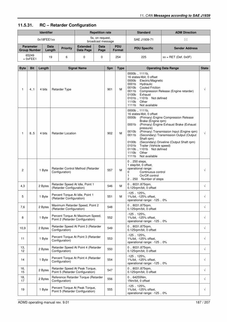
11. CAN Messages according to SAE J1939
ADM3 operating manual rev. 9.01 187 / 207
11.5.31. RC – Retarder Configuration
Identifier Repetition rate Standard ADM Direction
0x18FEE1xx 5s, on request,
broadcast message SAE J1939-71 �
Parameter Group Number
Data Length
Priority Extended Data Page
Data Page
PDU Format
PDU Specific Sender Address
65249 = 0xFEE1
19 6 0 0 254 225 xx = RET (Def. 0x0F)
Byte Bit Length Signal Name Spn Type Operating Data Range State
1 4..1 4 bits Retarder Type 901 M
0000b .. 1111b, 16 states/4bit, 0 offset 0000b Electric/Magnetic 0001b Hydraulic 0010b Cooled Friction 0011b Compression Release (Engine retarder) 0100b Exhaust 0101b .. 1101b Not defined 1110b Other 1111b Not available
√
1 8..5 4 bits Retarder Location 902 M
0000b .. 1111b, 16 states/4bit, 0 offset 0000b (Primary) Engine Compression Release Brake (Engine rpm) 0001b (Primary) Engine Exhaust Brake (Exhaust pressure) 0010b (Primary) Transmission Input (Engine rpm) 0011b (Secondary) Transmission Output (Output Shaft rpm) 0100b (Secondary) Driveline (Output Shaft rpm) 0101b Trailer (Vehicle speed) 0110b .. 1101b Not defined 1110b Other 1111b Not available
√
2 1 Byte Retarder Control Method (Retarder Configuration)
557 M
0 .. 250 steps, 1 step/bit, 0 offset, operational range: 0 Continuous control 1 On/Off control 2 .. 250 Number of steps
√
4,3 2 Bytes Retarder Speed At Idle, Point 1 (Retarder Configuration)
546 M 0 .. 8031.875rpm, 0.125rpm/bit, 0 offset
√
5 1 Byte Percent Torque At Idle, Point 1 (Retarder Configuration)
551 M -125 .. 125%, 1%/bit, -125% offset, operational range: -125 .. 0%
√
7,6 2 Bytes Maximum Retarder Speed, Point 2 (Retarder Configuration)
548 0 .. 8031.875rpm, 0.125rpm/bit, 0 offset
√
8 1 Byte Percent Torque At Maximum Speed, Point 2 (Retarder Configuration)
552 -125 .. 125%, 1%/bit, -125% offset, operational range: -125 .. 0%
√
10,9 2 Bytes Retarder Speed At Point 3 (Retarder Configuration)
549 0 .. 8031.875rpm, 0.125rpm/bit, 0 offset
√
11 1 Byte Percent Torque At Point 3 (Retarder Configuration)
553 -125 .. 125%, 1%/bit, -125% offset, operational range: -125 .. 0%
√
13, 12
2 Bytes Retarder Speed At Point 4 (Retarder Configuration)
550 0 .. 8031.875rpm, 0.125rpm/bit, 0 offset
√
14 1 Byte Percent Torque At Point 4 (Retarder Configuration)
554 -125 .. 125%, 1%/bit, -125% offset, operational range: -125 .. 0%
√
16, 15
2 Bytes Retarder Speed At Peak Torque, Point 5 (Retarder Configuration)
547 0 .. 8031.875rpm, 0.125rpm/bit, 0 offset
√
18, 17
2 Bytes Reference Retarder Torque (Retarder Configuration)
556 0 .. 64255Nm, 1Nm/bit, 0 offset
√
19 1 Byte Percent Torque At Peak Torque, Point 5 (Retarder Configuration)
555 -125 .. 125%, 1%/bit, -125% offset, operational range: -125 .. 0%
√

188 / 207 ADM3 operating manual rev. 9.01
11.5.32. EC1 – Engine Configuration 1
Identifier Repetition rate Standard ADM Direction
0x18FEE3xx 5s, on request,
broadcast message SAE J1939-71 �
Parameter Group Number
Data Length
Priority Extended Data Page
Data Page
PDU Format
PDU Specific Sender Address
65251 = 0xFEE3
341 6 0 0 254 227 xx = POW (Def. 0x00)
Byte Bit Length Signal Name Spn Type Operating Data Range State
2,1 2 Bytes Engine Speed At Idle, Point 1 (Engine Configuration)
188 M 0 .. 8031.875rpm, 0.125rpm/bit, 0 offset
√
3 1 Byte Engine Percent Torque At Idle, Point 1 (Engine Configuration)
539 M -125 .. 125%, 1%/bit, -125% offset, operational range: 0 .. 125%
√
5,4 2 Bytes Engine Speed At Point 2 (Engine Configuration)
528 M 0 .. 8031.875rpm, 0.125rpm/bit, 0 offset
√
6 1 Byte Engine Percent Torque At Point 2 (Engine Configuration)
540 M -125 .. 125%, 1%/bit, -125% offset, operational range: 0 .. 125%
√
8,7 2 Bytes Engine Speed At Point 3 (Engine Configuration)
529 M 0 .. 8031.875rpm, 0.125rpm/bit, 0 offset
√
9 1 Byte Engine Percent Torque At Point 3 (Engine Configuration)
541 M -125 .. 125%, 1%/bit, -125% offset, operational range: 0 .. 125%
√
11, 10
2 Bytes Engine Speed At Point 4 (Engine Configuration)
530 M 0 .. 8031.875rpm, 0.125rpm/bit, 0 offset
√
12 1 Byte Engine Percent Torque At Point 4 (Engine Configuration)
542 M -125 .. 125%, 1%/bit, -125% offset, operational range: 0 .. 125%
√
14, 13
2 Bytes Engine Speed At Point 5 (Engine Configuration)
531 M 0 .. 8031.875rpm, 0.125rpm/bit, 0 offset
√
15 1 Byte Engine Percent Torque At Point 5 (Engine Configuration)
543 M -125 .. 125%, 1%/bit, -125% offset, operational range: 0 .. 125%
√
17, 16
2 Bytes Engine Speed At High Idle, Point 6 (Engine Configuration)
532 M 0 .. 8031.875rpm, 0.125rpm/bit, 0 offset
√
19, 18
2 Bytes Engine Gain (Kp) Of The Endspeed Governor (Engine Configuration)
545 M 0 .. 50.2%/rpm, 1/1280%/rpm/bit, 0 offset, KP = delta Torque / delta Speed
-
21, 20
2 Bytes Engine Reference Torque (Engine Configuration)
544 M 0 .. 64255Nm, 1Nm/bit, 0 offset
√
23, 22
2 Bytes Engine Maximum Momentary Override Speed, Point 7 (Engine Configuration)
533 M 0 .. 8031.875rpm, 0.125rpm/bit, 0 offset
√
24 1 Byte Engine Maximum Momentary Override Time Limit (Engine Configuration)
534 M
0 .. 25s, 0.1s/bit, 0 offset, operational range: 0 .. 25s 0 No override of high idle allowed 255 Not applicable (no time restriction)
√
25 1 Byte Engine Requested Speed Control Range Lower Limit (Engine Configuration)
535 M 0 .. 2500rpm, 10rpm/bit, 0 offset
-
26 1 Byte Engine Requested Speed Control Range Upper Limit (Engine Configuration)
536 M 0 .. 2500rpm, 10rpm/bit, 0 offset
-
27 1 Byte Engine Requested Torque Control Range Lower Limit (Engine Configuration)
537 M -125 .. 125%, 1%/bit, -125% offset, operational range: 0 .. 125%
-
28 1 Byte Engine Requested Torque Control Range Upper Limit (Engine Configuration)
538 M -125 .. 125%, 1%/bit, -125% offset, operational range: 0 .. 125%
-
1 Due to compatibility reasons with other electronic control units the message data length is truncated to 34 Bytes according to the SAE
J1939-71 rev.2003 standard, newer versions of the standard provide up to 39 Bytes.
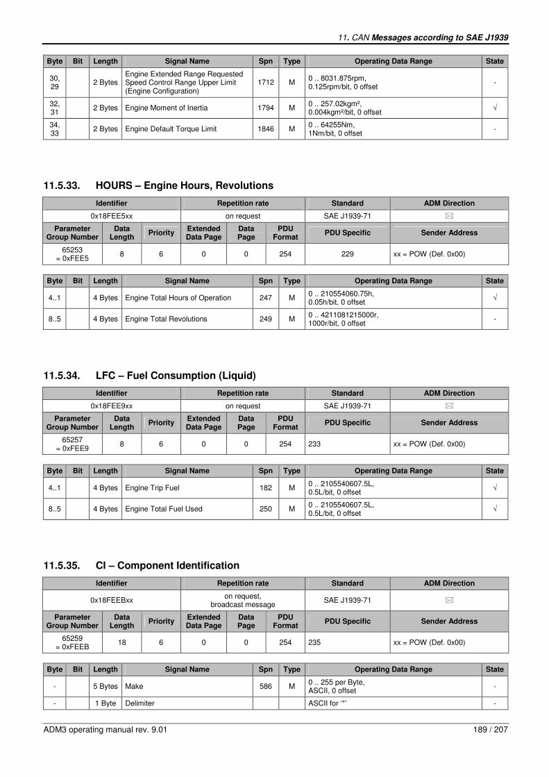
11. CAN Messages according to SAE J1939
ADM3 operating manual rev. 9.01 189 / 207
Byte Bit Length Signal Name Spn Type Operating Data Range State
30, 29
2 Bytes Engine Extended Range Requested Speed Control Range Upper Limit (Engine Configuration)
1712 M 0 .. 8031.875rpm, 0.125rpm/bit, 0 offset
-
32, 31
2 Bytes Engine Moment of Inertia 1794 M 0 .. 257.02kgm², 0.004kgm²/bit, 0 offset
√
34, 33
2 Bytes Engine Default Torque Limit 1846 M 0 .. 64255Nm, 1Nm/bit, 0 offset
-
11.5.33. HOURS – Engine Hours, Revolutions
Identifier Repetition rate Standard ADM Direction
0x18FEE5xx on request SAE J1939-71 �
Parameter Group Number
Data Length
Priority Extended Data Page
Data Page
PDU Format
PDU Specific Sender Address
65253 = 0xFEE5
8 6 0 0 254 229 xx = POW (Def. 0x00)
Byte Bit Length Signal Name Spn Type Operating Data Range State
4..1 4 Bytes Engine Total Hours of Operation 247 M 0 .. 210554060.75h, 0.05h/bit, 0 offset
√
8..5 4 Bytes Engine Total Revolutions 249 M 0 .. 4211081215000r, 1000r/bit, 0 offset
-
11.5.34. LFC – Fuel Consumption (Liquid)
Identifier Repetition rate Standard ADM Direction
0x18FEE9xx on request SAE J1939-71 �
Parameter Group Number
Data Length
Priority Extended Data Page
Data Page
PDU Format
PDU Specific Sender Address
65257 = 0xFEE9
8 6 0 0 254 233 xx = POW (Def. 0x00)
Byte Bit Length Signal Name Spn Type Operating Data Range State
4..1 4 Bytes Engine Trip Fuel 182 M 0 .. 2105540607.5L, 0.5L/bit, 0 offset
√
8..5 4 Bytes Engine Total Fuel Used 250 M 0 .. 2105540607.5L, 0.5L/bit, 0 offset
√
11.5.35. CI – Component Identification
Identifier Repetition rate Standard ADM Direction
0x18FEEBxx on request,
broadcast message SAE J1939-71 �
Parameter Group Number
Data Length
Priority Extended Data Page
Data Page
PDU Format
PDU Specific Sender Address
65259 = 0xFEEB
18 6 0 0 254 235 xx = POW (Def. 0x00)
Byte Bit Length Signal Name Spn Type Operating Data Range State
- 5 Bytes Make 586 M 0 .. 255 per Byte, ASCII, 0 offset
-
- 1 Byte Delimiter ASCII for ‘*’ -
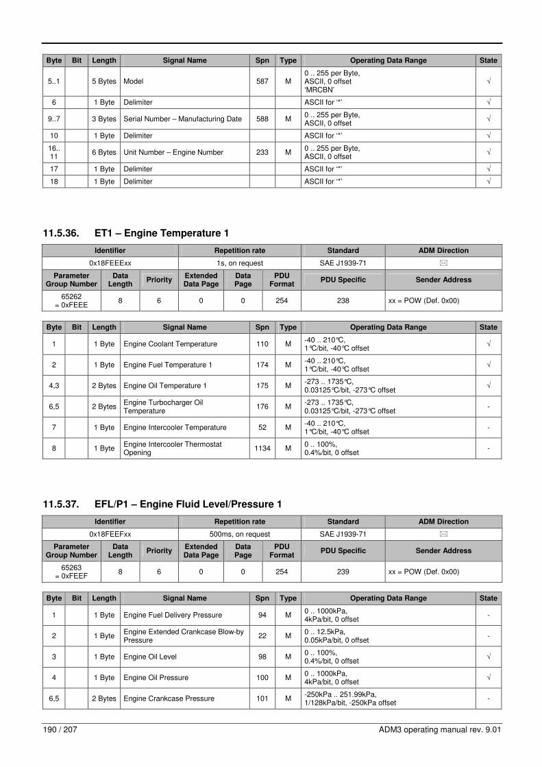
190 / 207 ADM3 operating manual rev. 9.01
Byte Bit Length Signal Name Spn Type Operating Data Range State
5..1 5 Bytes Model 587 M 0 .. 255 per Byte, ASCII, 0 offset ‘MRCBN’
√
6 1 Byte Delimiter ASCII for ‘*’ √
9..7 3 Bytes Serial Number – Manufacturing Date 588 M 0 .. 255 per Byte, ASCII, 0 offset
√
10 1 Byte Delimiter ASCII for ‘*’ √
16..11
6 Bytes Unit Number – Engine Number 233 M 0 .. 255 per Byte, ASCII, 0 offset
√
17 1 Byte Delimiter ASCII for ‘*’ √
18 1 Byte Delimiter ASCII for ‘*’ √
11.5.36. ET1 – Engine Temperature 1
Identifier Repetition rate Standard ADM Direction
0x18FEEExx 1s, on request SAE J1939-71 �
Parameter Group Number
Data Length
Priority Extended Data Page
Data Page
PDU Format
PDU Specific Sender Address
65262 = 0xFEEE
8 6 0 0 254 238 xx = POW (Def. 0x00)
Byte Bit Length Signal Name Spn Type Operating Data Range State
1 1 Byte Engine Coolant Temperature 110 M -40 .. 210°C, 1°C/bit, -40°C offset
√
2 1 Byte Engine Fuel Temperature 1 174 M -40 .. 210°C, 1°C/bit, -40°C offset
√
4,3 2 Bytes Engine Oil Temperature 1 175 M -273 .. 1735°C, 0.03125°C/bit, -273°C offset
√
6,5 2 Bytes Engine Turbocharger Oil Temperature
176 M -273 .. 1735°C, 0.03125°C/bit, -273°C offset
-
7 1 Byte Engine Intercooler Temperature 52 M -40 .. 210°C, 1°C/bit, -40°C offset
-
8 1 Byte Engine Intercooler Thermostat Opening
1134 M 0 .. 100%, 0.4%/bit, 0 offset
-
11.5.37. EFL/P1 – Engine Fluid Level/Pressure 1
Identifier Repetition rate Standard ADM Direction
0x18FEEFxx 500ms, on request SAE J1939-71 �
Parameter Group Number
Data Length
Priority Extended Data Page
Data Page
PDU Format
PDU Specific Sender Address
65263 = 0xFEEF
8 6 0 0 254 239 xx = POW (Def. 0x00)
Byte Bit Length Signal Name Spn Type Operating Data Range State
1 1 Byte Engine Fuel Delivery Pressure 94 M 0 .. 1000kPa, 4kPa/bit, 0 offset
-
2 1 Byte Engine Extended Crankcase Blow-by Pressure
22 M 0 .. 12.5kPa, 0.05kPa/bit, 0 offset
-
3 1 Byte Engine Oil Level 98 M 0 .. 100%, 0.4%/bit, 0 offset
√
4 1 Byte Engine Oil Pressure 100 M 0 .. 1000kPa, 4kPa/bit, 0 offset
√
6,5 2 Bytes Engine Crankcase Pressure 101 M -250kPa .. 251.99kPa, 1/128kPa/bit, -250kPa offset
-

11. CAN Messages according to SAE J1939
ADM3 operating manual rev. 9.01 191 / 207
Byte Bit Length Signal Name Spn Type Operating Data Range State
7 1 Byte Engine Coolant Pressure 109 M 0 .. 500kPa, 2kPa/bit, 0 offset
-
8 1 Byte Engine Coolant Level 111 M 0 .. 100%, 0.4%/bit, 0 offset
√
11.5.38. PTO – Power Takeoff Information
Identifier Repetition rate Standard ADM Direction
0x18FEF0xx 100ms SAE J1939-71 �
Parameter Group Number
Data Length
Priority Extended Data Page
Data Page
PDU Format
PDU Specific Sender Address
65264 = 0xFEF0
8 6 0 0 254 240 xx = POW (Def. 0x00)
Byte Bit Length Signal Name Spn Type Operating Data Range State
1 1 Byte Power Takeoff Oil Temperature 90 M -40 .. 210°C, 1°C/bit, -40°C offset
-
3,2 2 Bytes Power Takeoff Speed 186 M 0 .. 8031.875rpm, 0.125rpm/bit, 0 offset
-
5,4 2 Bytes Power Takeoff Set Speed 187 M 0 .. 8031.875rpm, 0.125rpm/bit, 0 offset
-
6 2,1 2 bits Engine PTO Enable Switch 980 M
00b .. 11b, 4 states/2bit, 0 offset 00b Off 01b On 10b Error 11b Not available
√
6 4,3 2 bits Engine Remote PTO Preprogrammed Speed Control Switch
979 M
00b .. 11b, 4 states/2bit, 0 offset 00b Off 01b On 10b Error 11b Not available
-
6 6,5 2 bits Engine Remote PTO Variable Speed Control Switch
978 M
00b .. 11b, 4 states/2bit, 0 offset 00b Off 01b On 10b Error 11b Not available
-
6 8,7 Not defined
7 2,1 2 bits Engine PTO Set Switch 984 M
00b .. 11b, 4 states/2bit, 0 offset 00b Off 01b On 10b Error 11b Not available
√
7 4,3 2 bits Engine PTO Coast/Decelerate Switch 983 M
00b .. 11b, 4 states/2bit, 0 offset 00b Off 01b On 10b Error 11b Not available
-
7 6,5 2 bits Engine PTO Resume Switch 982 M
00b .. 11b, 4 states/2bit, 0 offset 00b Off 01b On 10b Error 11b Not available
-
7 8,7 2 bits Engine PTO Accelerate Switch 981 M
00b .. 11b, 4 states/2bit, 0 offset 00b Off 01b On 10b Error 11b Not available
-
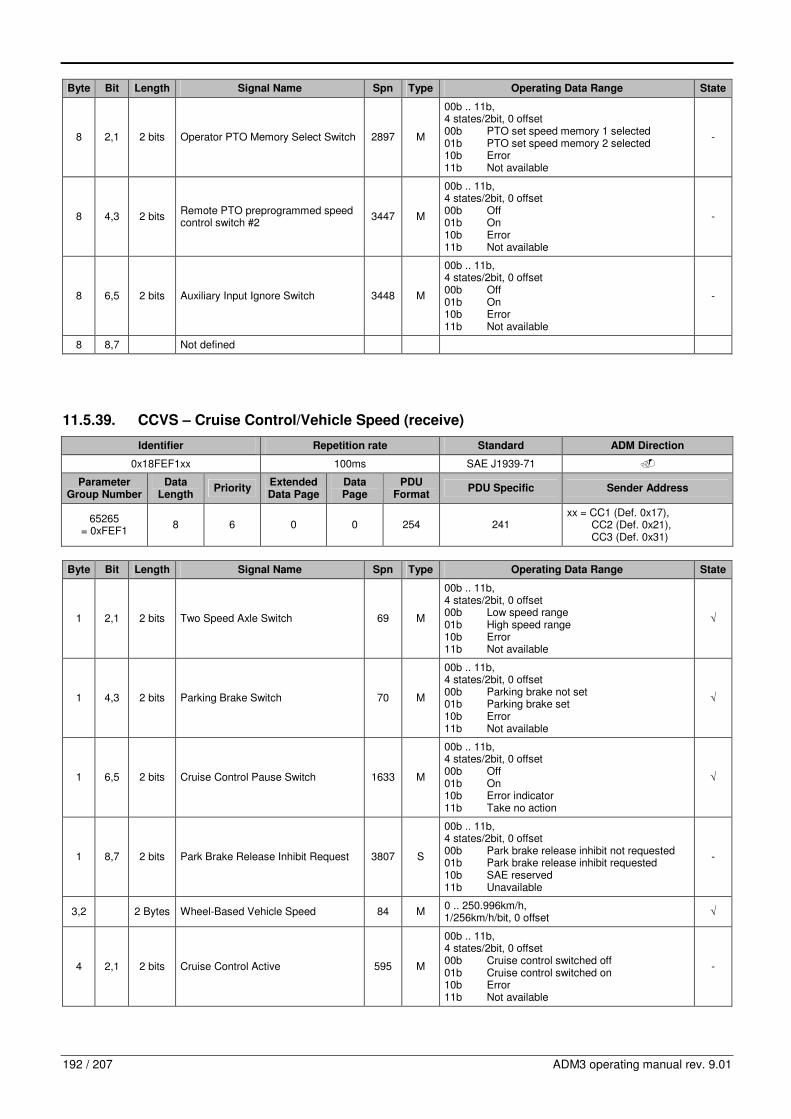
192 / 207 ADM3 operating manual rev. 9.01
Byte Bit Length Signal Name Spn Type Operating Data Range State
8 2,1 2 bits Operator PTO Memory Select Switch 2897 M
00b .. 11b, 4 states/2bit, 0 offset 00b PTO set speed memory 1 selected 01b PTO set speed memory 2 selected 10b Error 11b Not available
-
8 4,3 2 bits Remote PTO preprogrammed speed control switch #2
3447 M
00b .. 11b, 4 states/2bit, 0 offset 00b Off 01b On 10b Error 11b Not available
-
8 6,5 2 bits Auxiliary Input Ignore Switch 3448 M
00b .. 11b, 4 states/2bit, 0 offset 00b Off 01b On 10b Error 11b Not available
-
8 8,7 Not defined
11.5.39. CCVS – Cruise Control/Vehicle Speed (receive)
Identifier Repetition rate Standard ADM Direction
0x18FEF1xx 100ms SAE J1939-71 �
Parameter Group Number
Data Length
Priority Extended Data Page
Data Page
PDU Format
PDU Specific Sender Address
65265 = 0xFEF1
8 6 0 0 254 241 xx = CC1 (Def. 0x17), CC2 (Def. 0x21), CC3 (Def. 0x31)
Byte Bit Length Signal Name Spn Type Operating Data Range State
1 2,1 2 bits Two Speed Axle Switch 69 M
00b .. 11b, 4 states/2bit, 0 offset 00b Low speed range 01b High speed range 10b Error 11b Not available
√
1 4,3 2 bits Parking Brake Switch 70 M
00b .. 11b, 4 states/2bit, 0 offset 00b Parking brake not set 01b Parking brake set 10b Error 11b Not available
√
1 6,5 2 bits Cruise Control Pause Switch 1633 M
00b .. 11b, 4 states/2bit, 0 offset 00b Off 01b On 10b Error indicator 11b Take no action
√
1 8,7 2 bits Park Brake Release Inhibit Request 3807 S
00b .. 11b, 4 states/2bit, 0 offset 00b Park brake release inhibit not requested 01b Park brake release inhibit requested 10b SAE reserved 11b Unavailable
-
3,2 2 Bytes Wheel-Based Vehicle Speed 84 M 0 .. 250.996km/h, 1/256km/h/bit, 0 offset
√
4 2,1 2 bits Cruise Control Active 595 M
00b .. 11b, 4 states/2bit, 0 offset 00b Cruise control switched off 01b Cruise control switched on 10b Error 11b Not available
-

11. CAN Messages according to SAE J1939
ADM3 operating manual rev. 9.01 193 / 207
Byte Bit Length Signal Name Spn Type Operating Data Range State
4 4,3 2 bits Cruise Control Enable Switch 596 M
00b .. 11b, 4 states/2bit, 0 offset 00b Cruise control disabled 01b Cruise control enabled 10b Error 11b Not available
√
4 6,5 2 bits Brake Switch 597 M
00b .. 11b, 4 states/2bit, 0 offset 00b Brake pedal released 01b Brake pedal depressed 10b Error 11b Not available
√
4 8,7 2 bits Clutch Switch 598 M
00b .. 11b, 4 states/2bit, 0 offset 00b Clutch pedal released 01b Clutch pedal depressed 10b Error 11b Not available
√
5 2,1 2 bits Cruise Control Set Switch 599 M
00b .. 11b, 4 states/2bit, 0 offset 00b Cruise control activator not in position ‘set’ 01b Cruise control activator in position ‘set’ 10b Error 11b Not available
√
5 4,3 2 bits Cruise Control Coast (Decelerate) Switch
600 M
00b .. 11b, 4 states/2bit, 0 offset 00b Cruise control activator not in position ‘coast’ 01b Cruise control activator in position ‘coast’ 10b Error 11b Not available
√
5 6,5 2 bits Cruise Control Resume Switch 601 M
00b .. 11b, 4 states/2bit, 0 offset 00b Cruise control activator not in position ‘resume’ 01b Cruise control activator in position ‘resume’ 10b Error 11b Not available
√
5 8,7 2 bits Cruise Control Accelerate Switch 602 M
00b .. 11b, 4 states/2bit, 0 offset 00b Cruise control activator not in position ‘accelerate’ 01b Cruise control activator in position ‘accelerate’ 10b Error 11b Not available
√
6 1 Byte Cruise Control Set Speed 86 M 0 .. 250km/h, 1km/h/bit, 0 offset
-

194 / 207 ADM3 operating manual rev. 9.01
Byte Bit Length Signal Name Spn Type Operating Data Range State
7 5..1 5 bits PTO State 976 S
00000b .. 11111b, 32 states/5bit, 0 offset 00000b Off/Disabled 00001b Hold 00010b Remote Hold 00011b Standby 00100b Remote Standby 00101b Set 00110b Decelerate/Coast 00111b Resume 01000b Accelerate 01001b Accelerator Override 01010b Preprogrammed set speed 1 01011b Preprogrammed set speed 2 01100b Preprogrammed set speed 3 01101b Preprogrammed set speed 4 01110b Preprogrammed set speed 5 01111b Preprogrammed set speed 6 10000b Preprogrammed set speed 7 10001b Preprogrammed set speed 8 10010b PTO set speed memory 1 10011b PTO set speed memory 2 10100b .. 11110b Not defined 11111b Not available
-
7 8..6 3 bits Cruise Control States 527 S
000b .. 111b, 8 states/3bit, 0 offset 000b Off/Disabled 001b Hold 010b Accelerate 011b Decelerate/Coast 100b Resume 101b Set 110b Accelerator Override 111b Not available
-
8 2,1 2 bits Engine Idle Increment Switch 968 M
00b .. 11b, 4 states/2bit, 0 offset 00b Off 01b On 10b Error 11b Not available
-
8 4,3 2 bits Engine Idle Decrement Switch 967 M
00b .. 11b, 4 states/2bit, 0 offset 00b Off 01b On 10b Error 11b Not available
-
8 6,5 2 bits Engine Test Mode Switch 966 M
00b .. 11b, 4 states/2bit, 0 offset 00b Off 01b On 10b Error 11b Not available
-
8 8,7 2 bits Engine Shutdown Override Switch 1237 M
00b .. 11b, 4 states/2bit, 0 offset 00b Off 01b On 10b Error 11b Not available
-
11.5.40. CCVS – Cruise Control/Vehicle Speed (send)
Identifier Repetition rate Standard ADM Direction
0x18FEF1xx 100ms, on request SAE J1939-71 �
Parameter Group Number
Data Length
Priority Extended Data Page
Data Page
PDU Format
PDU Specific Sender Address
65265 = 0xFEF1
8 6 0 0 254 241 xx = POW (Def. 0x00)

11. CAN Messages according to SAE J1939
ADM3 operating manual rev. 9.01 195 / 207
Byte Bit Length Signal Name Spn Type Operating Data Range State
1 2,1 2 bits Two Speed Axle Switch 69 M
00b .. 11b, 4 states/2bit, 0 offset 00b Low speed range 01b High speed range 10b Error 11b Not available
√
1 4,3 2 bits Parking Brake Switch 70 M
00b .. 11b, 4 states/2bit, 0 offset 00b Parking brake not set 01b Parking brake set 10b Error 11b Not available
√
1 6,5 2 bits Cruise Control Pause Switch 1633 M
00b .. 11b, 4 states/2bit, 0 offset 00b Off 01b On 10b Error indicator 11b Take no action
-
1 8,7 2 bits Park Brake Release Inhibit Request 3807 S
00b .. 11b, 4 states/2bit, 0 offset 00b Park brake release inhibit not requested 01b Park brake release inhibit requested 10b SAE reserved 11b Unavailable
-
3,2 2 Bytes Wheel-Based Vehicle Speed 84 M 0 .. 250.996km/h, 1/256km/h/bit, 0 offset
√
4 2,1 2 bits Cruise Control Active 595 M
00b .. 11b, 4 states/2bit, 0 offset 00b Cruise control switched off 01b Cruise control switched on 10b Error 11b Not available
√
4 4,3 2 bits Cruise Control Enable Switch 596 M
00b .. 11b, 4 states/2bit, 0 offset 00b Cruise control disabled 01b Cruise control enabled 10b Error 11b Not available
√
4 6,5 2 bits Brake Switch 597 M
00b .. 11b, 4 states/2bit, 0 offset 00b Brake pedal released 01b Brake pedal depressed 10b Error 11b Not available
√
4 8,7 2 bits Clutch Switch 598 M
00b .. 11b, 4 states/2bit, 0 offset 00b Clutch pedal released 01b Clutch pedal depressed 10b Error 11b Not available
√
5 2,1 2 bits Cruise Control Set Switch 599 M
00b .. 11b, 4 states/2bit, 0 offset 00b Cruise control activator not in position ‘set’ 01b Cruise control activator in position ‘set’ 10b Error 11b Not available
√
5 4,3 2 bits Cruise Control Coast (Decelerate) Switch
600 M
00b .. 11b, 4 states/2bit, 0 offset 00b Cruise control activator not in position ‘coast’ 01b Cruise control activator in position ‘coast’ 10b Error 11b Not available
√
5 6,5 2 bits Cruise Control Resume Switch 601 M
00b .. 11b, 4 states/2bit, 0 offset 00b Cruise control activator not in position ‘resume’ 01b Cruise control activator in position ‘resume’ 10b Error 11b Not available
√
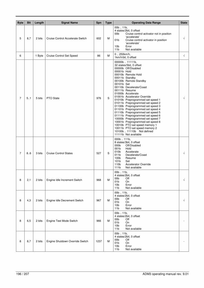
196 / 207 ADM3 operating manual rev. 9.01
Byte Bit Length Signal Name Spn Type Operating Data Range State
5 8,7 2 bits Cruise Control Accelerate Switch 602 M
00b .. 11b, 4 states/2bit, 0 offset 00b Cruise control activator not in position ‘accelerate’ 01b Cruise control activator in position ‘accelerate’ 10b Error 11b Not available
√
6 1 Byte Cruise Control Set Speed 86 M 0 .. 250km/h, 1km/h/bit, 0 offset
√
7 5..1 5 bits PTO State 976 S
00000b .. 11111b, 32 states/5bit, 0 offset 00000b Off/Disabled 00001b Hold 00010b Remote Hold 00011b Standby 00100b Remote Standby 00101b Set 00110b Decelerate/Coast 00111b Resume 01000b Accelerate 01001b Accelerator Override 01010b Preprogrammed set speed 1 01011b Preprogrammed set speed 2 01100b Preprogrammed set speed 3 01101b Preprogrammed set speed 4 01110b Preprogrammed set speed 5 01111b Preprogrammed set speed 6 10000b Preprogrammed set speed 7 10001b Preprogrammed set speed 8 10010b PTO set speed memory 1 10011b PTO set speed memory 2 10100b .. 11110b Not defined 11111b Not available
√
7 8..6 3 bits Cruise Control States 527 S
000b .. 111b, 8 states/3bit, 0 offset 000b Off/Disabled 001b Hold 010b Accelerate 011b Decelerate/Coast 100b Resume 101b Set 110b Accelerator Override 111b Not available
√
8 2,1 2 bits Engine Idle Increment Switch 968 M
00b .. 11b, 4 states/2bit, 0 offset 00b Off 01b On 10b Error 11b Not available
√
8 4,3 2 bits Engine Idle Decrement Switch 967 M
00b .. 11b, 4 states/2bit, 0 offset 00b Off 01b On 10b Error 11b Not available
√
8 6,5 2 bits Engine Test Mode Switch 966 M
00b .. 11b, 4 states/2bit, 0 offset 00b Off 01b On 10b Error 11b Not available
-
8 8,7 2 bits Engine Shutdown Override Switch 1237 M
00b .. 11b, 4 states/2bit, 0 offset 00b Off 01b On 10b Error 11b Not available
-

11. CAN Messages according to SAE J1939
ADM3 operating manual rev. 9.01 197 / 207
11.5.41. LFE – Fuel Economy (Liquid)
Identifier Repetition rate Standard ADM Direction
0x18FEF2xx 100ms, on request SAE J1939-71 �
Parameter Group Number
Data Length
Priority Extended Data Page
Data Page
PDU Format
PDU Specific Sender Address
65266 = 0xFEF2
8 6 0 0 254 242 xx = POW (Def. 0x00)
Byte Bit Length Signal Name Spn Type Operating Data Range State
2,1 2 Bytes Engine Fuel Rate 183 M 0 .. 3212.75L/h, 0.05L/h/bit, 0 offset
√
4,3 2 Bytes Engine Instantaneous Fuel Economy 184 M 0 .. 125.5km/L, 1/512km/L/bit, 0 offset
√
6,5 2 Bytes Engine Average fuel Economy 185 M 0 .. 125.5km/L, 1/512km/L/bit, 0 offset
√
7 1 Byte Engine Throttle Position 51 M 0 .. 100%, 0.4%/bit, 0 offset
-
8 1 Byte Engine Throttle Position 3673 M 0 .. 100%, 0.4%/bit, 0 offset
-
11.5.42. AMB – Ambient Conditions (receive)
Identifier Repetition rate Standard ADM Direction
0x18FEF5xx 1s SAE J1939-71 �
Parameter Group Number
Data Length
Priority Extended Data Page
Data Page
PDU Format
PDU Specific Sender Address
65269 = 0xFEF5
8 6 0 0 254 245 xx = TEMP (Def. 0x21)
Byte Bit Length Signal Name Spn Type Operating Data Range State
1 1 Byte Barometric Pressure 108 M 0 .. 125kPa, 0.5kPa/bit, 0 offset
-
3,2 2 Bytes Cab Interior Temperature 170 M -273 .. 1735°C, 0.03125°C/bit, -273°C offset
-
5,4 2 Bytes Ambient Air Temperature 171 M -273 .. 1735°C, 0.03125°C/bit, -273°C offset
√
6 1 Byte Engine Air Inlet Temperature 172 M -40 .. 210°C, 1°C/bit, -40°C offset
-
8,7 2 Bytes Road Surface Temperature 79 M -273 .. 1735°C, 0.03125°C/bit, -273°C offset
-
11.5.43. AMB – Ambient Conditions (send)
Identifier Repetition rate Standard ADM Direction
0x18FEF5xx 1s SAE J1939-71 �
Parameter Group Number
Data Length
Priority Extended Data Page
Data Page
PDU Format
PDU Specific Sender Address
65269 = 0xFEF5
8 6 0 0 254 245 xx = POW (Def. 0x00)
Byte Bit Length Signal Name Spn Type Operating Data Range State
1 1 Byte Barometric Pressure 108 M 0 .. 125kPa, 0.5kPa/bit, 0 offset
√
3,2 2 Bytes Cab Interior Temperature 170 M -273 .. 1735°C, 0.03125°C/bit, -273°C offset
-
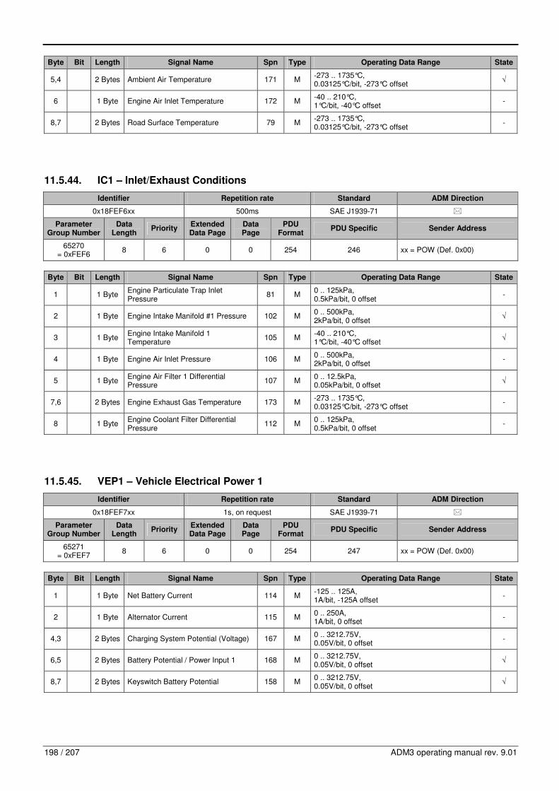
198 / 207 ADM3 operating manual rev. 9.01
Byte Bit Length Signal Name Spn Type Operating Data Range State
5,4 2 Bytes Ambient Air Temperature 171 M -273 .. 1735°C, 0.03125°C/bit, -273°C offset
√
6 1 Byte Engine Air Inlet Temperature 172 M -40 .. 210°C, 1°C/bit, -40°C offset
-
8,7 2 Bytes Road Surface Temperature 79 M -273 .. 1735°C, 0.03125°C/bit, -273°C offset
-
11.5.44. IC1 – Inlet/Exhaust Conditions
Identifier Repetition rate Standard ADM Direction
0x18FEF6xx 500ms SAE J1939-71 �
Parameter Group Number
Data Length
Priority Extended Data Page
Data Page
PDU Format
PDU Specific Sender Address
65270 = 0xFEF6
8 6 0 0 254 246 xx = POW (Def. 0x00)
Byte Bit Length Signal Name Spn Type Operating Data Range State
1 1 Byte Engine Particulate Trap Inlet Pressure
81 M 0 .. 125kPa, 0.5kPa/bit, 0 offset
-
2 1 Byte Engine Intake Manifold #1 Pressure 102 M 0 .. 500kPa, 2kPa/bit, 0 offset
√
3 1 Byte Engine Intake Manifold 1 Temperature
105 M -40 .. 210°C, 1°C/bit, -40°C offset
√
4 1 Byte Engine Air Inlet Pressure 106 M 0 .. 500kPa, 2kPa/bit, 0 offset
-
5 1 Byte Engine Air Filter 1 Differential Pressure
107 M 0 .. 12.5kPa, 0.05kPa/bit, 0 offset
√
7,6 2 Bytes Engine Exhaust Gas Temperature 173 M -273 .. 1735°C, 0.03125°C/bit, -273°C offset
-
8 1 Byte Engine Coolant Filter Differential Pressure
112 M 0 .. 125kPa, 0.5kPa/bit, 0 offset
-
11.5.45. VEP1 – Vehicle Electrical Power 1
Identifier Repetition rate Standard ADM Direction
0x18FEF7xx 1s, on request SAE J1939-71 �
Parameter Group Number
Data Length
Priority Extended Data Page
Data Page
PDU Format
PDU Specific Sender Address
65271 = 0xFEF7
8 6 0 0 254 247 xx = POW (Def. 0x00)
Byte Bit Length Signal Name Spn Type Operating Data Range State
1 1 Byte Net Battery Current 114 M -125 .. 125A, 1A/bit, -125A offset
-
2 1 Byte Alternator Current 115 M 0 .. 250A, 1A/bit, 0 offset
-
4,3 2 Bytes Charging System Potential (Voltage) 167 M 0 .. 3212.75V, 0.05V/bit, 0 offset
-
6,5 2 Bytes Battery Potential / Power Input 1 168 M 0 .. 3212.75V, 0.05V/bit, 0 offset
√
8,7 2 Bytes Keyswitch Battery Potential 158 M 0 .. 3212.75V, 0.05V/bit, 0 offset
√
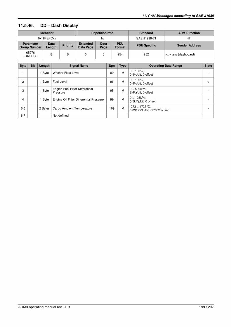
11. CAN Messages according to SAE J1939
ADM3 operating manual rev. 9.01 199 / 207
11.5.46. DD – Dash Display
Identifier Repetition rate Standard ADM Direction
0x18FEFCxx 1s SAE J1939-71 �
Parameter Group Number
Data Length
Priority Extended Data Page
Data Page
PDU Format
PDU Specific Sender Address
65276 = 0xFEFC
8 6 0 0 254 252 xx = any (dashboard)
Byte Bit Length Signal Name Spn Type Operating Data Range State
1 1 Byte Washer Fluid Level 80 M 0 .. 100%, 0.4%/bit, 0 offset
-
2 1 Byte Fuel Level 96 M 0 .. 100%, 0.4%/bit, 0 offset
√
3 1 Byte Engine Fuel Filter Differential Pressure
95 M 0 .. 500kPa, 2kPa/bit, 0 offset
-
4 1 Byte Engine Oil Filter Differential Pressure 99 M 0 .. 125kPa, 0.5kPa/bit, 0 offset
-
6,5 2 Bytes Cargo Ambient Temperature 169 M -273 .. 1735°C, 0.03125°C/bit, -273°C offset
-
8,7 Not defined

200 / 207 ADM3 operating manual rev. 9.01
11.6. CAN message details of diagnostic messages
11.6.1. DM13 – Diagnostic Message 13, Stop Start Broadcast
Identifier Repetition rate Standard ADM Direction
0x18DFyyxx
sent whenever a Stop or Start Broadcast is necessary, Hold
Signal every 5s for maintainance of modified state
SAE J1939-73, SAE J1939-21
�
Parameter Group Number
Data Length
Priority Extended Data Page
Data Page
PDU Format
PDU Specific Sender Address
57088 = 0xDF00
8 6 0 0 223 Destination Address: yy = POW (Def. 0x00), RET (Def. 0x0F)
xx = any
Byte Bit Length Signal Name Spn Type Operating Data Range State
1 2,1 2 bits SAE J1939 Network #1, Primary vehicle network
639 S
00b .. 11b 00b Stop Broadcast 01b Start Broadcast 10b Reserved 11b Don’t Care/take no action (leave as is)
√
1 4,3 2 bits SAE J1922 622 S
00b .. 11b 00b Stop Broadcast 01b Start Broadcast 10b Reserved 11b Don’t Care/take no action (leave as is)
-
1 6,5 2 bits SAE J1587 608 S
00b .. 11b 00b Stop Broadcast 01b Start Broadcast 10b Reserved 11b Don’t Care/take no action (leave as is)
√
1 8,7 2 bits Current Data Link 1230 S
00b .. 11b 00b Stop Broadcast 01b Start Broadcast 10b Reserved 11b Don’t Care/take no action (leave as is)
√
2 2,1 2 bits Other, Manufacture Specified Port 1234 S
00b .. 11b 00b Stop Broadcast 01b Start Broadcast 10b Reserved 11b Don’t Care/take no action (leave as is)
-
2 4,3 2 bits SAE J1850 1233 S
00b .. 11b 00b Stop Broadcast 01b Start Broadcast 10b Reserved 11b Don’t Care/take no action (leave as is)
-
2 6,5 2 bits ISO 9141 1232 S
00b .. 11b 00b Stop Broadcast 01b Start Broadcast 10b Reserved 11b Don’t Care/take no action (leave as is)
-
2 8,7 2 bits SAE J1939 Network #2 1231 S
00b .. 11b 00b Stop Broadcast 01b Start Broadcast 10b Reserved 11b Don’t Care/take no action (leave as is)
-
3 2,1 2 bits SAE Reserved
3 4,3 2 bits SAE Reserved
3 6,5 2 bits SAE Reserved
3 8,7 2 bits SAE J1939 Network #3 1235 S
00b .. 11b 00b Stop Broadcast 01b Start Broadcast 10b Reserved 11b Don’t Care/take no action (leave as is)
-
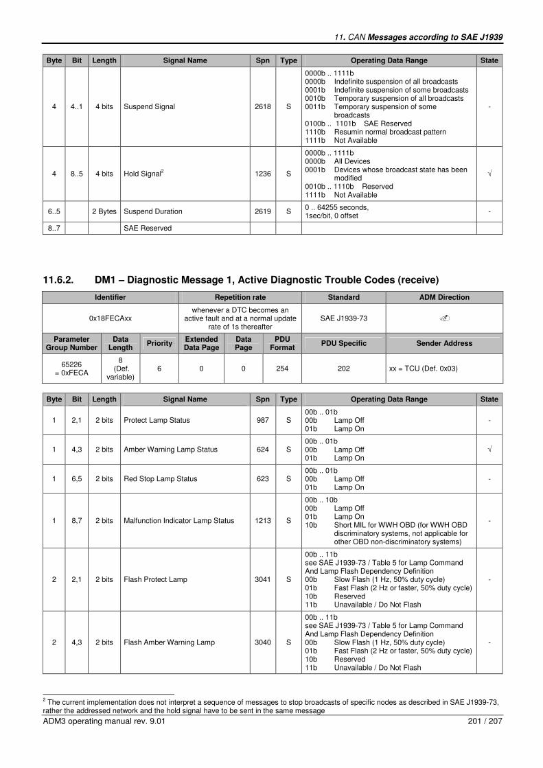
11. CAN Messages according to SAE J1939
ADM3 operating manual rev. 9.01 201 / 207
Byte Bit Length Signal Name Spn Type Operating Data Range State
4 4..1 4 bits Suspend Signal 2618 S
0000b .. 1111b 0000b Indefinite suspension of all broadcasts 0001b Indefinite suspension of some broadcasts 0010b Temporary suspension of all broadcasts 0011b Temporary suspension of some broadcasts 0100b .. 1101b SAE Reserved 1110b Resumin normal broadcast pattern 1111b Not Available
-
4 8..5 4 bits Hold Signal2 1236 S
0000b .. 1111b 0000b All Devices 0001b Devices whose broadcast state has been modified 0010b .. 1110b Reserved 1111b Not Available
√
6..5 2 Bytes Suspend Duration 2619 S 0 .. 64255 seconds, 1sec/bit, 0 offset
-
8..7 SAE Reserved
11.6.2. DM1 – Diagnostic Message 1, Active Diagnostic Trouble Codes (receive)
Identifier Repetition rate Standard ADM Direction
0x18FECAxx whenever a DTC becomes an
active fault and at a normal update rate of 1s thereafter
SAE J1939-73 �
Parameter Group Number
Data Length
Priority Extended Data Page
Data Page
PDU Format
PDU Specific Sender Address
65226 = 0xFECA
8 (Def.
variable) 6 0 0 254 202 xx = TCU (Def. 0x03)
Byte Bit Length Signal Name Spn Type Operating Data Range State
1 2,1 2 bits Protect Lamp Status 987 S 00b .. 01b 00b Lamp Off 01b Lamp On
-
1 4,3 2 bits Amber Warning Lamp Status 624 S 00b .. 01b 00b Lamp Off 01b Lamp On
√
1 6,5 2 bits Red Stop Lamp Status 623 S 00b .. 01b 00b Lamp Off 01b Lamp On
-
1 8,7 2 bits Malfunction Indicator Lamp Status 1213 S
00b .. 10b 00b Lamp Off 01b Lamp On 10b Short MIL for WWH OBD (for WWH OBD discriminatory systems, not applicable for other OBD non-discriminatory systems)
-
2 2,1 2 bits Flash Protect Lamp 3041 S
00b .. 11b see SAE J1939-73 / Table 5 for Lamp Command And Lamp Flash Dependency Definition 00b Slow Flash (1 Hz, 50% duty cycle) 01b Fast Flash (2 Hz or faster, 50% duty cycle) 10b Reserved 11b Unavailable / Do Not Flash
-
2 4,3 2 bits Flash Amber Warning Lamp 3040 S
00b .. 11b see SAE J1939-73 / Table 5 for Lamp Command And Lamp Flash Dependency Definition 00b Slow Flash (1 Hz, 50% duty cycle) 01b Fast Flash (2 Hz or faster, 50% duty cycle) 10b Reserved 11b Unavailable / Do Not Flash
-
2 The current implementation does not interpret a sequence of messages to stop broadcasts of specific nodes as described in SAE J1939-73,
rather the addressed network and the hold signal have to be sent in the same message
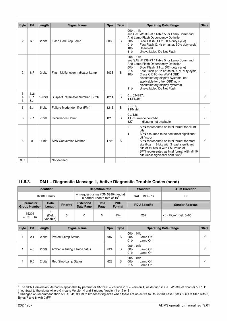
202 / 207 ADM3 operating manual rev. 9.01
Byte Bit Length Signal Name Spn Type Operating Data Range State
2 6,5 2 bits Flash Red Stop Lamp 3039 S
00b .. 11b see SAE J1939-73 / Table 5 for Lamp Command And Lamp Flash Dependency Definition 00b Slow Flash (1 Hz, 50% duty cycle) 01b Fast Flash (2 Hz or faster, 50% duty cycle) 10b Reserved 11b Unavailable / Do Not Flash
-
2 8,7 2 bits Flash Malfunction Indicator Lamp 3038 S
00b .. 11b see SAE J1939-73 / Table 5 for Lamp Command And Lamp Flash Dependency Definition 00b Slow Flash (1 Hz, 50% duty cycle) 01b Fast Flash (2 Hz or faster, 50% duty cycle) 10b Class C DTC (for WWH OBD discriminatory display Systems, not applicable for other OBD non- discriminatory display systems) 11b Unavailable / Do Not Flash
-
5 4 3
8..6 8..1 8..1
19 bits Suspect Parameter Number (SPN) 1214 S 0 .. 524287, 1 SPN/bit
√
5 5..1 5 bits Failure Mode Identifier (FMI) 1215 S 0 .. 31, 1 FMI/bit
-
6 7..1 7 bits Occurrence Count 1216 S 0 .. 126, 1 Occurrence count/bit 127 Indicating not available
-
6 8 1 bit SPN Conversion Method 1706 S
0 SPN represented as Intel format for all 19 bits 1 SPN assumed to be sent most significant bit first or SPN represented as Intel format for most significant 16 bits with 3 least significant bits of 19 bits in with FMI value or SPN represented as Intel format with all 19 bits (least significant sent first)
3
√
8..7 Not defined
11.6.3. DM1 – Diagnostic Message 1, Active Diagnostic Trouble Codes (send)
Identifier Repetition rate Standard ADM Direction
0x18FECAxx on request using PGN 59904 and at
a normal update rate of 1s4
SAE J1939-73 �
Parameter Group Number
Data Length
Priority Extended Data Page
Data Page
PDU Format
PDU Specific Sender Address
65226 = 0xFECA
8 (Def.
variable) 6 0 0 254 202 xx = POW (Def. 0x00)
Byte Bit Length Signal Name Spn Type Operating Data Range State
1 2,1 2 bits Protect Lamp Status 987 S 00b .. 01b 00b Lamp Off 01b Lamp On
√
1 4,3 2 bits Amber Warning Lamp Status 624 S 00b .. 01b 00b Lamp Off 01b Lamp On
√
1 6,5 2 bits Red Stop Lamp Status 623 S 00b .. 01b 00b Lamp Off 01b Lamp On
√
3 The SPN Conversion Method is applicable by parameter 01/18 (0 = Version 2, 1 = Version 4) as defined in SAE J1939-73 chapter 5.7.1.11
in contrast to the signal where 0 means Version 4 and 1 means Version 1 or 2 or 3 4 Changed on recommendation of SAE J1939/73 to broadcasting even when there are no active faults, in this case Bytes 3..6 are filled with 0,
Bytes 7 and 8 with 0xFF
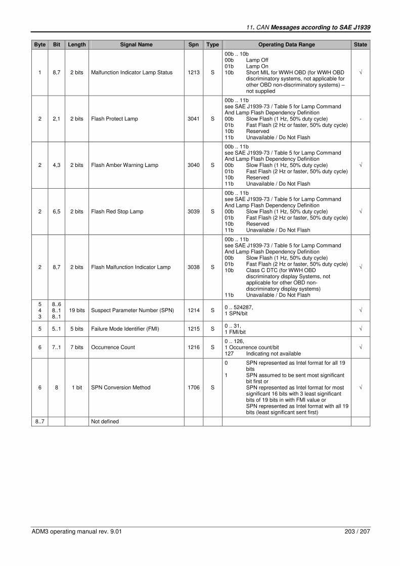
11. CAN Messages according to SAE J1939
ADM3 operating manual rev. 9.01 203 / 207
Byte Bit Length Signal Name Spn Type Operating Data Range State
1 8,7 2 bits Malfunction Indicator Lamp Status 1213 S
00b .. 10b 00b Lamp Off 01b Lamp On 10b Short MIL for WWH OBD (for WWH OBD discriminatory systems, not applicable for other OBD non-discriminatory systems) – not supplied
√
2 2,1 2 bits Flash Protect Lamp 3041 S
00b .. 11b see SAE J1939-73 / Table 5 for Lamp Command And Lamp Flash Dependency Definition 00b Slow Flash (1 Hz, 50% duty cycle) 01b Fast Flash (2 Hz or faster, 50% duty cycle) 10b Reserved 11b Unavailable / Do Not Flash
-
2 4,3 2 bits Flash Amber Warning Lamp 3040 S
00b .. 11b see SAE J1939-73 / Table 5 for Lamp Command And Lamp Flash Dependency Definition 00b Slow Flash (1 Hz, 50% duty cycle) 01b Fast Flash (2 Hz or faster, 50% duty cycle) 10b Reserved 11b Unavailable / Do Not Flash
√
2 6,5 2 bits Flash Red Stop Lamp 3039 S
00b .. 11b see SAE J1939-73 / Table 5 for Lamp Command And Lamp Flash Dependency Definition 00b Slow Flash (1 Hz, 50% duty cycle) 01b Fast Flash (2 Hz or faster, 50% duty cycle) 10b Reserved 11b Unavailable / Do Not Flash
√
2 8,7 2 bits Flash Malfunction Indicator Lamp 3038 S
00b .. 11b see SAE J1939-73 / Table 5 for Lamp Command And Lamp Flash Dependency Definition 00b Slow Flash (1 Hz, 50% duty cycle) 01b Fast Flash (2 Hz or faster, 50% duty cycle) 10b Class C DTC (for WWH OBD discriminatory display Systems, not applicable for other OBD non- discriminatory display systems) 11b Unavailable / Do Not Flash
√
5 4 3
8..6 8..1 8..1
19 bits Suspect Parameter Number (SPN) 1214 S 0 .. 524287, 1 SPN/bit
√
5 5..1 5 bits Failure Mode Identifier (FMI) 1215 S 0 .. 31, 1 FMI/bit
√
6 7..1 7 bits Occurrence Count 1216 S 0 .. 126, 1 Occurrence count/bit 127 Indicating not available
√
6 8 1 bit SPN Conversion Method 1706 S
0 SPN represented as Intel format for all 19 bits 1 SPN assumed to be sent most significant bit first or SPN represented as Intel format for most significant 16 bits with 3 least significant bits of 19 bits in with FMI value or SPN represented as Intel format with all 19 bits (least significant sent first)
√
8..7 Not defined
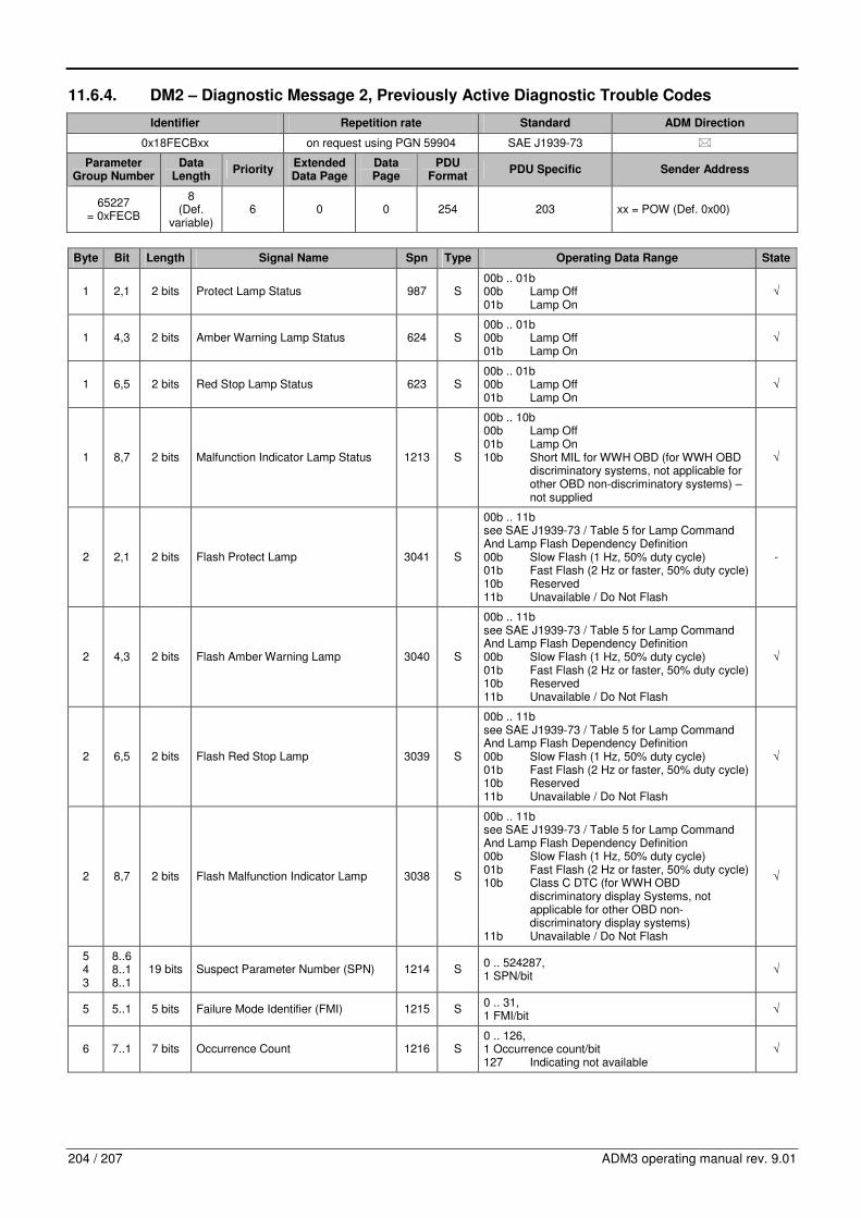
204 / 207 ADM3 operating manual rev. 9.01
11.6.4. DM2 – Diagnostic Message 2, Previously Active Diagnostic Trouble Codes
Identifier Repetition rate Standard ADM Direction
0x18FECBxx on request using PGN 59904 SAE J1939-73 �
Parameter Group Number
Data Length
Priority Extended Data Page
Data Page
PDU Format
PDU Specific Sender Address
65227 = 0xFECB
8 (Def.
variable) 6 0 0 254 203 xx = POW (Def. 0x00)
Byte Bit Length Signal Name Spn Type Operating Data Range State
1 2,1 2 bits Protect Lamp Status 987 S 00b .. 01b 00b Lamp Off 01b Lamp On
√
1 4,3 2 bits Amber Warning Lamp Status 624 S 00b .. 01b 00b Lamp Off 01b Lamp On
√
1 6,5 2 bits Red Stop Lamp Status 623 S 00b .. 01b 00b Lamp Off 01b Lamp On
√
1 8,7 2 bits Malfunction Indicator Lamp Status 1213 S
00b .. 10b 00b Lamp Off 01b Lamp On 10b Short MIL for WWH OBD (for WWH OBD discriminatory systems, not applicable for other OBD non-discriminatory systems) – not supplied
√
2 2,1 2 bits Flash Protect Lamp 3041 S
00b .. 11b see SAE J1939-73 / Table 5 for Lamp Command And Lamp Flash Dependency Definition 00b Slow Flash (1 Hz, 50% duty cycle) 01b Fast Flash (2 Hz or faster, 50% duty cycle) 10b Reserved 11b Unavailable / Do Not Flash
-
2 4,3 2 bits Flash Amber Warning Lamp 3040 S
00b .. 11b see SAE J1939-73 / Table 5 for Lamp Command And Lamp Flash Dependency Definition 00b Slow Flash (1 Hz, 50% duty cycle) 01b Fast Flash (2 Hz or faster, 50% duty cycle) 10b Reserved 11b Unavailable / Do Not Flash
√
2 6,5 2 bits Flash Red Stop Lamp 3039 S
00b .. 11b see SAE J1939-73 / Table 5 for Lamp Command And Lamp Flash Dependency Definition 00b Slow Flash (1 Hz, 50% duty cycle) 01b Fast Flash (2 Hz or faster, 50% duty cycle) 10b Reserved 11b Unavailable / Do Not Flash
√
2 8,7 2 bits Flash Malfunction Indicator Lamp 3038 S
00b .. 11b see SAE J1939-73 / Table 5 for Lamp Command And Lamp Flash Dependency Definition 00b Slow Flash (1 Hz, 50% duty cycle) 01b Fast Flash (2 Hz or faster, 50% duty cycle) 10b Class C DTC (for WWH OBD discriminatory display Systems, not applicable for other OBD non- discriminatory display systems) 11b Unavailable / Do Not Flash
√
5 4 3
8..6 8..1 8..1
19 bits Suspect Parameter Number (SPN) 1214 S 0 .. 524287, 1 SPN/bit
√
5 5..1 5 bits Failure Mode Identifier (FMI) 1215 S 0 .. 31, 1 FMI/bit
√
6 7..1 7 bits Occurrence Count 1216 S 0 .. 126, 1 Occurrence count/bit 127 Indicating not available
√

11. CAN Messages according to SAE J1939
ADM3 operating manual rev. 9.01 205 / 207
Byte Bit Length Signal Name Spn Type Operating Data Range State
6 8 1 bit SPN Conversion Method 1706 S
0 SPN represented as Intel format for all 19 bits 1 SPN assumed to be sent most significant bit first or SPN represented as Intel format for most significant 16 bits with 3 least significant bits of 19 bits in with FMI value or SPN represented as Intel format with all 19 bits (least significant sent first)
5
√
8..7 Not defined
11.6.5. DM3 – Diagnostic Message 3, Diagnostic Data Clear/Reset Of Previously Active DTCs
Identifier Repetition rate Standard ADM Direction
0x18FECCxx on request using PGN 59904, a
NACK is required if PG is not supported
6
SAE J1939-73, SAE J1939-21
�
Parameter Group Number
Data Length
Priority Extended Data Page
Data Page
PDU Format
PDU Specific Sender Address
65228 = 0xFECC
0 6 0 0 254 204 xx = POW (Def. 0x00), RET (Def. 0x0F)
Byte Bit Length Signal Name Spn Type Operating Data Range State
11.6.6. DM4 – Diagnostic Message 4, Freeze Frame Parameters
Identifier Repetition rate Standard ADM Direction
0x18FECDxx on request using PGN 59904, a
NACK is required if PG is not supported
SAE J1939-73, SAE J1939-71
�
Parameter Group Number
Data Length
Priority Extended Data Page
Data Page
PDU Format
PDU Specific Sender Address
65229 = 0xFECD
variable7 6 0 0 254 205 xx = POW (Def. 0x00)
Byte Bit Length Signal Name Spn Type Operating Data Range State
1 1 Byte Freeze Frame Length 1217 S 0 .. 255, 1 Byte/bit
√
4 3 2
8..6 8..1 8..1
19 bits Suspect Parameter Number (SPN) 1214 S 0 .. 524287, 1 SPN/bit
√
4 5..1 5 bits Failure Mode Identifier (FMI) 1215 S 0 .. 31, 1 FMI/bit
√
5 7..1 7 bits Occurrence Count 1216 S 0 .. 126, 1 Occurrence count/bit 127 Indicating not available
√
5 Compare footnote 3 for send message DM1
6 DM3 requests to POW clear all DTCs (active and previously active) and are answered with an ACK, requests to RET are answered with a
NACK 7 No Manufacturer Specific Information is sent, therefore the Freeze Frame Length derives as 13 Bytes per DTC, both active and previously
active DTCs are sent in this message
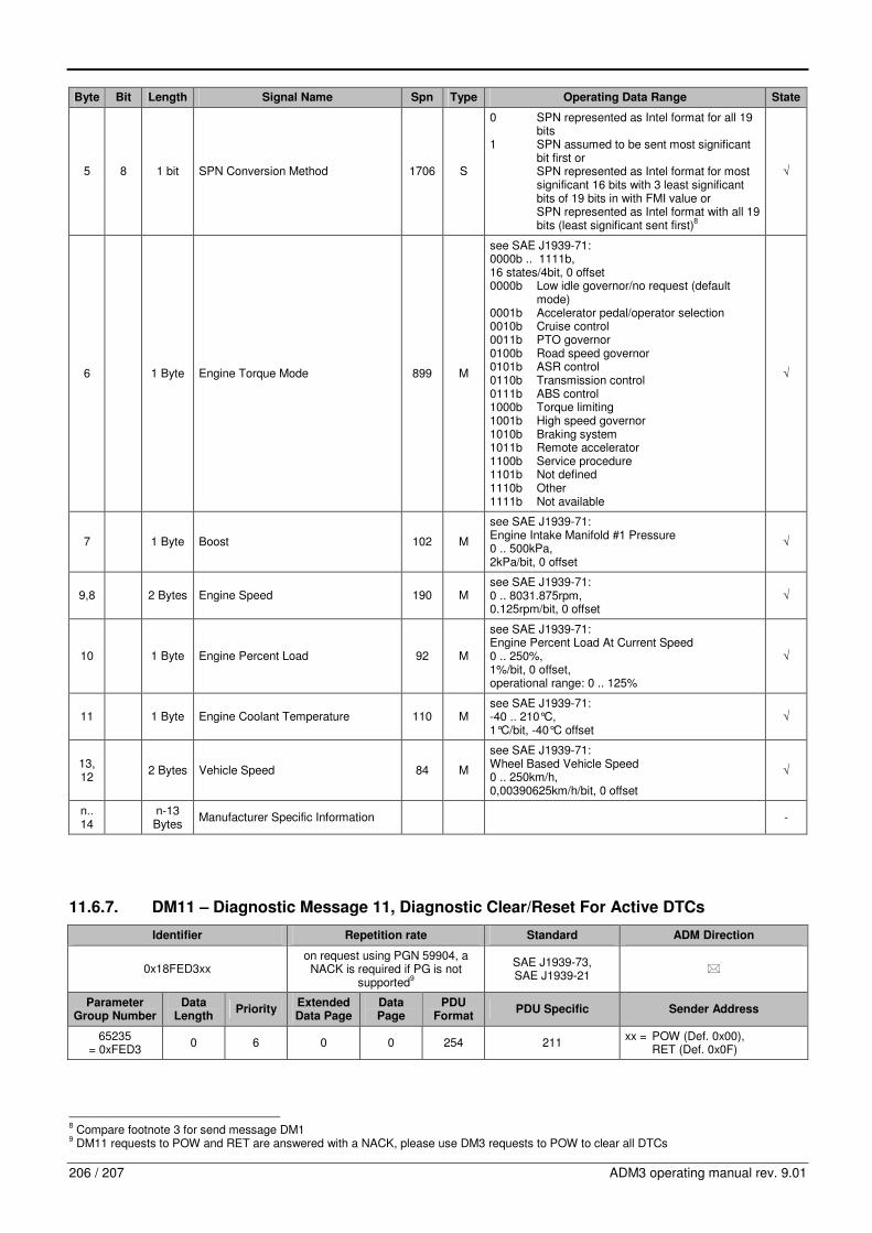
206 / 207 ADM3 operating manual rev. 9.01
Byte Bit Length Signal Name Spn Type Operating Data Range State
5 8 1 bit SPN Conversion Method 1706 S
0 SPN represented as Intel format for all 19 bits 1 SPN assumed to be sent most significant bit first or SPN represented as Intel format for most significant 16 bits with 3 least significant bits of 19 bits in with FMI value or SPN represented as Intel format with all 19 bits (least significant sent first)
8
√
6 1 Byte Engine Torque Mode 899 M
see SAE J1939-71: 0000b .. 1111b, 16 states/4bit, 0 offset 0000b Low idle governor/no request (default mode) 0001b Accelerator pedal/operator selection 0010b Cruise control 0011b PTO governor 0100b Road speed governor 0101b ASR control 0110b Transmission control 0111b ABS control 1000b Torque limiting 1001b High speed governor 1010b Braking system 1011b Remote accelerator 1100b Service procedure 1101b Not defined 1110b Other 1111b Not available
√
7 1 Byte Boost 102 M
see SAE J1939-71: Engine Intake Manifold #1 Pressure 0 .. 500kPa, 2kPa/bit, 0 offset
√
9,8 2 Bytes Engine Speed 190 M see SAE J1939-71: 0 .. 8031.875rpm, 0.125rpm/bit, 0 offset
√
10 1 Byte Engine Percent Load 92 M
see SAE J1939-71: Engine Percent Load At Current Speed 0 .. 250%, 1%/bit, 0 offset, operational range: 0 .. 125%
√
11 1 Byte Engine Coolant Temperature 110 M see SAE J1939-71: -40 .. 210°C, 1°C/bit, -40°C offset
√
13, 12
2 Bytes Vehicle Speed 84 M
see SAE J1939-71: Wheel Based Vehicle Speed 0 .. 250km/h, 0,00390625km/h/bit, 0 offset
√
n.. 14
n-13 Bytes
Manufacturer Specific Information -
11.6.7. DM11 – Diagnostic Message 11, Diagnostic Clear/Reset For Active DTCs
Identifier Repetition rate Standard ADM Direction
0x18FED3xx on request using PGN 59904, a
NACK is required if PG is not supported
9
SAE J1939-73, SAE J1939-21
�
Parameter Group Number
Data Length
Priority Extended Data Page
Data Page
PDU Format
PDU Specific Sender Address
65235 = 0xFED3
0 6 0 0 254 211 xx = POW (Def. 0x00), RET (Def. 0x0F)
8 Compare footnote 3 for send message DM1
9 DM11 requests to POW and RET are answered with a NACK, please use DM3 requests to POW to clear all DTCs

11. CAN Messages according to SAE J1939
ADM3 operating manual rev. 9.01 207 / 207
Byte Bit Length Signal Name Spn Type Operating Data Range State