mendenhall elementary school - ms dallas€¦ · mendenhall elementary school employee childcare...
TRANSCRIPT
Mendenhall Elementary School
Employee Childcare
Plano I.S.D.
Plano, Texas
Page 2 of 2
VLK Architects, 2011 ADDENDUM NO. 1 2905.00
1.04 DOCUMENT 00 2120 - INSTRUCTIONS TO PROPOSERS (MENDENHALL DAYCARE CENTER
RENOVATION AND ADDITION AND BYRD CENTER PAVING REPLACEMENT ONLY)
A. This Document, attached hereto, is entirely new and is hereby made a part of this Addendum.
1.05 DOCUMENT 00 3100 - PROJECT DESCRIPTION (MENDENHALL DAYCARE CENTER
RENOVATION AND ADDITION AND BYRD CENTER PAVING REPLACEMENT ONLY)
A. This Document, attached hereto, is entirely new and is hereby made a part of this Addendum.
1.06 DOCUMENT 00 4205 - BID PROPOSAL FORM (MENDENHALL DAYCARE CENTER
RENOVATION AND ADDITION AND BYRD CENTER PAVING REPLACEMENT ONLY)
A. This Document, attached hereto, is entirely new and is hereby made a part of this Addendum.
1.07 DOCUMENT 00 5227 - SUBCONTRACT (MENDENHALL DAYCARE CENTER RENOVATION AND
ADDITION AND BYRD CENTER PAVING REPLACEMENT ONLY)
A. This Document, attached hereto, is entirely new and is hereby made a part of this Addendum.
1.08 DOCUMENT 00 6217 - STANDARD INSURANCE REQUIREMENTS FOR SUBCONTRACTORS
(MENDENHALL DAYCARE CENTER RENOVATION AND ADDITION AND BYRD CENTER PAVING
REPLACEMENT ONLY)
A. This Document, attached hereto, is entirely new and is hereby made a part of this Addendum.
1.09 SECTION 22 4201 - PLUMBING FIXTURES (EMPLOYEE CHILDCARE ONLY)
A. This section, attached hereto, is entirely new and is hereby made a part of this Exhibit “A”.
1.10 SECTION 23 0701 - INSULATION (EMPLOYEE CHILDCARE ONLY)
A. This section, attached hereto, is entirely new and is hereby made a part of this Exhibit “A”.
1.11 SECTION 23 3001 - HVAC AIR DISTRIBUTION (EMPLOYEE CHILDCARE ONLY)
A. This section, attached hereto, is entirely new and is hereby made a part of this Exhibit “A”.
END OF ADDENDUM NO. 1
INVITATION TO BID Plano I.S.D.
Mendenhall Daycare Center Renovation and Addition and Byrd Center Paving Replacement
Bid Due Date: Tuesday, February 1, 2011; 4:00 P.M. Architect: VLK Architects 1161 Corporate Drive West Suite 300 Arlington, Texas 76006 Phone: 817-633-1600 ATTN: Brian Harlan Construction Manager: Starling Richardson Construction, Inc. 1201 Kas Drive, Suite D Richardson, Texas 75081 Telephone: 972-238-8131 Fax: 972-238-8144 Attn: Jim Starling or Eric Stanaland Starling Richardson Construction, Inc., hereinafter referred to as “Construction Manager”
for Plano Independent School District, invites you to bid on Mendenhall Daycare Center Renovation and Addition, located at 1313 18th Street, Plano, Texas, 75074 and Byrd Center Paving Replacement, located at 1300 19th Street, Suite D, Plano, Texas,
75074. All bids may be submitted on your Bid Form and shall be in accordance with the Contract Documents, which include, but are not limited to, the Drawings, Specifications,
Instructions to Proposers, and other applicable documents. Bid documents my be reviewed at the following plan rooms: Associated General Contractors, Construction Information Network, DFW Minority Plan Room, Hispanic Contractor’s Association, McGraw Hill Plan Room, Reed Construction Data, at the Construction Manager’s office, or on the Construction Manager’s ftp site (if you have visited this site before, refresh your web browser in each folder to ensure the most current information is displayed):
ftp://mail.starlingrichardson.com username: srcftp
password: starling Bid Documents may be obtained for a refundable deposit of $100.00, payable to Plano ISD, by contacting MS DALLAS, 2300 REAGAN STREET, DALLAS, TEXAS 75219, (214-521-7000). Deposits will be refunded in full if complete documents are returned in good condition to the Construction Manager. DO NOT RETURN DOCUMENTS TO THE PRINTER – DOCUMENTS RETURNED TO THE PRINTER WILL BE REFUSED. The shipping and/or postage expense of the delivery of documents shall be at the Offeror’s expense.
INVITATION TO BID PAGE 2 OF 2 Proposals may be mailed or faxed or hand carried to the Construction Manager’s office at 1201 Kas Drive, Suite D, Richardson, Texas, 75081. The fax number is 972-238-8144.. Bids must be received by 4:00 P.M., February 1, 2011. Any bids received after 4:00 P.M. will not be accepted. Starling Richardson Construction, Inc. reserves the right to reject any or all proposals and to waive irregularities or informalities as may be deemed in the Owner’s interest. Any questions regarding scope that occur must be submitted in writing to Starling Richardson Construction, Inc., at the above-listed address, or may be faxed to 972-238-8144. Telephone calls will be accepted regarding scope issues, but responses must be confirmed in writing to be valid. Questions should be directed to Jim Starling. It shall be the responsibility of the bidder to contact the Construction Manager or the Architect and verify the latest issuance of Bid Documents, including any Addenda, and to further verify bid amount reflects the Bid Documents in effect at time of bid. Each bidder is required to examine the Bid Documents and make written request to the Construction Manager for interpretations or correction of any ambiguity, inconsistency or error therein which he may discover. Only written documentation and confirmations through Addenda will be considered binding. Statutory Bonds for performance of the contract and for payments of mechanics and materials MAY be required in an amount equal to 100% of the accepted proposal. Offerors must be capable of providing such bonds if required and must supply the cost as an add option with their proposal. There will be a Pre-Proposal conference held the PISD Service Center, 6600 Alma Drive, Plano, Texas, 75023, at 10:00 AM, on TUESDAY, JANUARY 18, 2011. SPECIAL CONDITIONS No proposals for sitework, site utilities, or landscaping will be accepted on the Mendenhall Daycare Center. These trades shall only provide proposals for the Byrd Center Paving Replacement. Bidders are cautioned that the existing adjacent facility will be in use by faculty and students during the construction time frame. All appropriate precautions are to be taken in regard to maintaining the safety of faculty and students. No interaction between staff/students and construction personnel will be permitted. END OF INVITATION

INSTRUCTIONS TO PROPOSERS
1. Proposals: Proposals are due in Starling Richardson Construction’s office in Richardson, Texas,
by 4:00 PM, February 1, 2011. A Bid Proposal form is attached for your use. Company letterhead proposals are acceptable. Proposals can be mailed, e-mailed, or faxed in to Starling Richardson’s office, 1201 Kas Drive, Suite D, Richardson, Texas 75081, 972-238-8131 (phone); 972-238-8144 (fax); [email protected] (e-mail address); prior to the specified date and time established for receipt of proposals. If a subcontractor/supplier e-mails a bid, Starling Richardson Construction requests a hard copy to be mailed as confirmation.
Each proposer shall provide separate proposals for the Mendenhall Daycare Renovation and Addition and the Byrd Center Paving Replacement. No proposals for sitework, site utilities, or landscaping will be accepted on the Mendenhall Daycare Center. These trades shall only provide proposals for the Byrd Center Paving Replacement.
2. Contract Forms: The Construction Manager’s Standard Form of Agreement between Construction
Manager and Subcontractor (Stipulated Sum) included in the specifications will be used to execute the contract between the Construction Manager and Subcontractor.
Failure of a Subcontractor to review this agreement shall not constitute a reason for
said firm not to execute the agreement. If a Subcontractor fails or refuses to execute said agreement for any reason, it will be the responsibility of the Subcontractor to reimburse the Construction Manager for all additional cost incurred by the Construction Manager in obtaining the services of another firm to perform the work as required.
3. Responsible Contractor: A contract will only be made with a subcontractor who is found to be responsible.
To be responsible, the subcontractor must possess the demonstrated ability to perform successfully the terms and conditions of the project stated in all proposal documents. Owner or Construction Manager reserves the right to reject any proposal where the subcontractor is not considered responsible or where unfavorable comments are received from references.
The following factors will be considered in evaluating whether a subcontractor is
responsible to perform this project: Ability to complete project on time, ability to provide daily full-time project supervision with an experienced supervisor who has prior experience with projects of the scope and type; past relationship with the Owner or Construction Manager; integrity, honesty, and reputation; record of past performance on projects of this size and type; skill and quality of finished work; financial capacity, possession of the necessary facilities, equipment, personnel,
tooling and technical resources, insurance and bonding requirement and such other factors as Owner or Construction Manager deems relevant.
4. Subcontractor Insurance: Subcontractor shall, at its own cost, purchase and maintain
in force until all of Subcontractor’s obligations are discharged, all policies of insurance required to be provided by the Construction Manager or its subcontractors including, but not limited to, the following policies of insurance, which or insurance have limits and coverages of not less than the greater of these specified here or elsewhere in the Contract Documents. (See Separate Attachment)
5. Project Time: Time is of the essence in the completion requirements of this project.
This subcontractor shall at all times coordinate and perform this subcontract in accordance with the schedule and keep up with the overall progress of the project to avoid delaying the work of other subcontractors. The Construction Manager shall schedule, sequence, and coordinate the work activities of the overall construction project. The subcontractor shall, at all times and at no additional cost, provide sufficient manpower, materials, and equipment as required to keep up with the progress of the overall work of the project. THIS INCLUDES SATURDAYS, SUNDAYS, HOLIDAYS, AND OVERTIME WORK IF REQUIRED. If it is possible for the Construction Manager to coordinate and sequence the work of this subcontract with the work of other subcontractors for completion prior to the expiration of the duration specified, then it shall be compulsory for this subcontractor, without additional cost, to provide its fullest effort and cooperation as may be required to lessen the duration of the overall schedule to the maximum extent possible
6. Trash Disposal and Clean Up: All subcontractors fully understand and have taken
into consideration in their proposal all funds necessary to clean up their own debris, trash and rubble generated by their scope of work.
7. Attention is called to the fact that the Owner is exempt from the payment of the
State Sales Tax normally levied against material costs. The contract sum, as identified by the Base, shall not include any allowances for the payment of State Sales Tax on materials required to complete the work. The successful Proposer, upon award of the contract, will be furnished with a permit number, which will enable him to purchase the required materials without payment of such taxes.
8. All definitions set forth in the General Conditions of the Contract for Construction,
AIA Document A201, and the Supplementary General Conditions included in the Project Manual are applicable to the Instructions to Proposers.
9. Bidding Documents include the Advertisement or Invitation to Bid, Instructions to
Proposers, and the proposed contract documents, including any addenda issued prior to receipt of proposals.
10. Addenda are written or graphic instruments issued prior to the execution of the contract which modify or interpret the bidding documents, including drawings and the project manual, by additions, deletions, clarifications or corrections. Addenda will become part of the contract documents when the construction contract is executed.
11. Each proposer, by making his proposal, represents that he has read and understands
the bidding documents. 12. Each proposer, by making his proposal, represents that he has familiarized himself
with the local conditions under which work is to be performed. 13. All proposals must be prepared and submitted in accordance with the Instructions to
Proposers. When the proposal contains multiple “Proposal Items”, it shall be understood that the Owner may award each Proposal Item separately, or in any combination that the Owner chooses.
14. A proposal is invalid if it has not been deposited at the designated location prior to
the time and date for receipt of bids indicated in the Advertisement or Invitation to Bid, or prior to any extension thereof issued to the proposers.
15. Unless otherwise provided in any supplement to the Instruction to Proposers, no
proposer shall modify, withdraw or cancel his proposal or any part thereof for thirty (30) days after the time designated for the receipt of bids in the Advertisement or Invitation to Bid.
16. Each proposer shall examine the bidding documents carefully, and not later than
seven (7) days prior to the date for receipt of proposals, shall make written request to the Architect for interpretation or correction of any ambiguity, inconsistency or error therein which he may discover. Any interpretation or correction will be issued as an addendum by the Architects. Only a written interpretation or correction by an addendum shall be binding. No proposer shall rely upon any interpretation or correction given by any other method. Each proposer represents that his proposal is based upon the material and equipment described in the bidding documents.
17. No substitution will be considered unless written request has been submitted to the
Architect for approval at least ten (10) days prior to the date for receipt of bids. Each such request shall include a complete description of the proposed substitute, the name of the material or equipment for which it is to be substituted, drawings, cuts, performance and test data and any other data or information necessary for a complete evaluation. If the Architect approves any proposed substitution, such approval will be set forth in an Addendum.
18. The Proposer acknowledges the right of the Owner and Construction Manager to
reject any or all proposals and to waive any informality or irregularity in any proposal received. In addition, the Proposer recognizes the right of the Owner to
reject a bid if the bidder failed to furnish any required bid security or to submit the data required by the bidding documents or if the bid is in any way incomplete or irregular.
19. Guarantees: Besides guarantees required elsewhere, subcontractors shall guarantee
the work in general for one year from the date of substantial completion. Subcontractors shall be held responsible for and must make good any effects arising or discovered in any part of his work within warranty period. Where detailed specifications call for guarantees as above specified, they shall cover the special features called for. All guarantees must be submitted to the Construction Manager before the final payment request will be approved.
SECTION 00 3100
Project Description
Mendenhall Daycare Addition and Renovation consists of a 3,000 SF addition and renovation to the 4,850 SF existing Kindergarten wing of Mendenhall Elementary School. The remaining existing elementary school will be demolished as part of the original Mendenhall Elementary School project which has already been awarded. Construction of the Mendenhall Daycare Addition and Renovation will begin on or about June 27, 2011, following the demolition of the existing elementary school, with substantial completion on December 17, 2011. The Byrd Center Paving Replacement project consists of replacement of the existing asphalt and concrete parking lot and drives with concrete paving and lime stabilized subgrade. This project will also include site utilities, pavement striping and signage, and lighting. Construction is scheduled to begin on or about June 6, 2011 with substantial completion on August 12, 2011. Time is of the essence in the completion requirements of this project. This subcontractor shall at all times coordinate and perform this subcontract in accordance with the schedule and keep up with the overall progress of the project to avoid delaying the work of other subcontractors. The Construction Manager shall schedule, sequence, and coordinate the work activities of the overall construction project. The subcontractor shall, at all times and at no additional cost, provide sufficient manpower, materials, and equipment as required to keep up with the progress of the overall work of the project. THIS INCLUDES SATURDAYS, SUNDAYS, HOLIDAYS, AND OVERTIME WORK IF REQUIRED. If it is possible for the Construction Manager to coordinate and sequence the work of this subcontract with the work of other subcontractors for completion prior to the expiration of the duration specified, then it shall be compulsory for this subcontractor, without additional cost, to provide its fullest effort and cooperation as may be required to lessen the duration of the overall schedule to the maximum extent possible.
00 3100 PROJECTION DESCRIPTION
BID PROPOSAL FORM PROJECT: Mendenhall Daycare Center CONSTRUCTION MANAGER:
1313 18th Street Starling Richardson Construction, Inc. Plano, Texas 1201 Kas Drive, Suite D Richardson, Texas
Phone: 972-238-8131, Fax: 972-238-9171 OWNER: Plano ISD ARCHITECT: VLK Architects Name of Bidder: Address of Bidder: Phone Number: Fax Number: E-mail: Bidder Certifies That:
• This Bid is submitted in compliance with the contract documents; • Bidder has had the opportunity to inspect the project site; • Bidder proposes to furnish all labor, materials, tools, equipment and services required to construct all work in the bid category in accordance with the contract documents; • Bidder agrees to enter into an agreement with the Construction Manager for said work. BASE BID
Bidder agrees to perform all work for bid category(ies) as described in the contract documents for the base bid(s) stated below. For each category to be bid, write the bid category number, description, and bid amount in both words and figures. In case of discrepancy, the amount shown in words will govern.
Specification Section(s): Description:
For the Lump Sum of:
Dollars $
Specification Section(s): Description:
For the Lump Sum of:
Dollars $
Specification Section(s): Description:
For the Lump Sum of:
Dollars $
Specification Section(s): Description:
For the Lump Sum of:
Dollars $
Specification Section(s): Description:
For the Lump Sum of:
Dollars $
Specification Section(s): Description:
For the Lump Sum of:
Dollars $
Bid Proposal Form 1 of 4
COMBINED BID:
Bidders may submit a combined bid for any of the Bid Categories. Bidders must also submit separate bids for each Bid Category included in a Combined Bid.
Bid Categories
Descriptions
For the Lump Sum of: ($ )
Dollars
ALTERNATES (IF APPLICABLE) The following mandatory alternates are required by the respective bid category. The bidder agrees that the amounts indicated shall be added or deducted from the base bid for each alternate.
Alt. 1 (description of alt.)
Add $
VALUE ENGINEERING OR SUBSTITUTE MANUFACTURER ALTERNATIVES (These will not be used to determine the lowest qualified bidder) We offer the following alternates to the names, makes, types, or styles specified:
Article, Work or Specified Name Alternate Name, Make, Add Deduct Process Make, Type or Style Type or Style
$ $
$ $
$ $
COST OF BOND (IF REQUIRED):
ADDENDA
Bidder acknowledges receipt of the following Addenda issued during the bid period.
Addendum dated Addendum dated
Addendum dated Addendum dated EXECUTION
The undersigned agrees to provisions of the contract documents. The individual signing this Bid Proposal Form on behalf of Bidder warrants that he/she has the authority to do so and agrees to furnish Construction Manager written proof of such authority upon request. Signature: Date:
Printed Name: Title: Submit one (1) copy of Bid Proposal Form.
- End of Proposal Form -
Bid Proposal Form 2 of 4
BID PROPOSAL FORM PROJECT: Byrd Center Paving Replacement CONSTRUCTION MANAGER:
1300 19th Street, Suite D Starling Richardson Construction, Inc. Plano, Texas 1201 Kas Drive, Suite D Richardson, Texas
Phone: 972-238-8131, Fax: 972-238-9171 OWNER: Plano ISD ARCHITECT: VLK Architects Name of Bidder: Address of Bidder: Phone Number: Fax Number: E-mail: Bidder Certifies That:
• This Bid is submitted in compliance with the contract documents; • Bidder has had the opportunity to inspect the project site; • Bidder proposes to furnish all labor, materials, tools, equipment and services required to construct all work in the bid category in accordance with the contract documents; • Bidder agrees to enter into an agreement with the Construction Manager for said work. BASE BID
Bidder agrees to perform all work for bid category(ies) as described in the contract documents for the base bid(s) stated below. For each category to be bid, write the bid category number, description, and bid amount in both words and figures. In case of discrepancy, the amount shown in words will govern.
Specification Section(s): Description:
For the Lump Sum of:
Dollars $
Specification Section(s): Description:
For the Lump Sum of:
Dollars $
Specification Section(s): Description:
For the Lump Sum of:
Dollars $
Specification Section(s): Description:
For the Lump Sum of:
Dollars $
Specification Section(s): Description:
For the Lump Sum of:
Dollars $
Specification Section(s): Description:
For the Lump Sum of:
Dollars $
Bid Proposal Form 3 of 4

Bid Proposal Form 4 of 4
COMBINED BID:
Bidders may submit a combined bid for any of the Bid Categories. Bidders must also submit separate bids for each Bid Category included in a Combined Bid.
Bid Categories
Descriptions
For the Lump Sum of: ($ )
Dollars
ALTERNATES (IF APPLICABLE) The following mandatory alternates are required by the respective bid category. The bidder agrees that the amounts indicated shall be added or deducted from the base bid for each alternate.
Alt. 1 (description of alt.)
Add $
VALUE ENGINEERING OR SUBSTITUTE MANUFACTURER ALTERNATIVES (These will not be used to determine the lowest qualified bidder) We offer the following alternates to the names, makes, types, or styles specified:
Article, Work or Specified Name Alternate Name, Make, Add Deduct Process Make, Type or Style Type or Style
$ $
$ $
$ $
COST OF BOND (IF REQUIRED):
ADDENDA
Bidder acknowledges receipt of the following Addenda issued during the bid period.
Addendum dated Addendum dated
Addendum dated Addendum dated EXECUTION
The undersigned agrees to provisions of the contract documents. The individual signing this Bid Proposal Form on behalf of Bidder warrants that he/she has the authority to do so and agrees to furnish Construction Manager written proof of such authority upon request. Signature: Date:
Printed Name: Title: Submit one (1) copy of Bid Proposal Form.
- End of Proposal Form -
-1-
STARLING RICHARDSON CONSTRUCTION 1201 Kas Drive, Suite D Richardson, Texas 75081
(972) 238-8131 (972) 238-9171 - fax
SUBCONTRACT
Date: _______________________________ Subcontractor: __________________________ Contractor: Starling Richardson Construction Address: _______________________________ Project Name: _________________________ Attn: __________________________________ Address: _____________________________ Telephone No.: ___________________________ Starling Richardson Subcontract No.: _______ Fax No.: ________________________________ E-Mail Address: _______________________ E-Mail Address: ___________________________ 1. Subcontractor shall perform all work and furnish all supervision, labor, materials, plans, scaffolding, tools, equipment, supplies, and anything else necessary for the construction and completion of all work described in Exhibit A, and all work incidental thereto or reasonably inferable therefrom, in strict accordance and in full compliance with the terms of the Contract Documents, as defined and described in Exhibit A (all of which is hereinafter referred to as the “Work”).
2. Contractor shall pay Subcontractor, for the performance of the Work, subject to additions and deductions by change order or other Subcontract provisions, the total sum of ____________________________ Dollars ($____________).
3. Applications for payment shall be submitted monthly on a date to be determined by Contractor. Payments shall be made to Subcontractor within five (5) working days of receipt of payment from Owner subject to the terms and conditions contained in the Starling Richardson General Provisions.
4. Payment and performance bonds (are not) required in a form attached as Exhibit B.
5. Retainage shall be withheld from each pay application in the amount of ____%.
6. Subcontractor must furnish a certificate of insurance in accordance with Contractor’s Subcontractor’s Minimum Insurance Requirements attached as Exhibit C and obtain all required insurance prior to commencing its Work.
7. The terms and conditions contained in the following documents, including Starling Richardson General Provisions - Article 2.5, Indemnification, which are attached hereto, are incorporated herein by reference as if fully written out:
Starling Richardson General Provisions Pages 1 through 16 (Dated_________) Exhibit A Page 1 through _______ Exhibit B Pages 1 and 2 Exhibit C Page 1
8. Reference to Contractor shall refer to Starling Richardson Construction.
“Subcontractor” “Contractor” STARLING RICHARDSON CONSTRUCTION ______________________________________ ___________________________________________ Signature Signature ______________________________________ ___________________________________________ Printed Name Printed Name ______________________________________ ___________________________________________ Title Title Date: ________________________________ Date: _____________________________________
-2-
STARLING RICHARDSON GENERAL PROVISIONS
ARTICLE 1 CONTRACT DOCUMENTS
1.1 DEFINITIONS 1.1.1 THE CONTRACT DOCUMENTS
.1 The Contract Documents consist of the Agreement between Contractor and the Owner (“Agreement”), General Conditions of the Contract, Supplementary and other Conditions, Exhibits and Riders enumerated and attached to the Agreement, all addenda issued prior to and all modifications issued after execution of the Agreement, and plans and specifications.
.2 Subcontractor acknowledges and agrees that its Subcontract and the Contract Documents are adequate and sufficient to provide for the performance and completion of the Work, and include all Work, whether or not shown or specified, which reasonably may be inferred to be required for the completion of the Work in accordance with all applicable laws, codes and professional standards.
1.1.2 THE SUBCONTRACT
.1 The Subcontract represents the entire and integrated Agreement between the parties and supersedes all prior negotiations, representations or agreements, whether written or oral.
.2 The Subcontract may not be construed to create any contractual relationship of any kind between Subcontractor and Owner, between Subcontractor and Architect or between any persons or entities other than Contractor and Subcontractor.
.3 Until Subcontractor’s obligations under this Subcontract are completely fulfilled, Subcontractor agrees not to perform any Work directly for the Owner or any of its tenants, or deal directly with the Owner’s representatives in connection with the Project, unless directed in writing by Contractor.
.4 With respect to the Work covered by this Subcontract, Subcontractor shall assume all obligations, risks and responsibilities to Contractor which Contractor has assumed toward the Owner and Contractor shall have all rights and remedies with respect to Subcontractor as Owner has with respect to Contractor, in the Contract Documents, except to the extent of any conflict with the Subcontract.
1.1.3 THE WORK
The Work of Subcontractor shall include the performing and furnishing by Subcontractor of all supervision, labor, materials, plans, scaffolding, hoisting, tools, equipment, supplies, and all other things necessary for the construction and completion of the Work, as described in its Subcontract, and all Work incidental thereto or reasonably inferable therefrom, in strict accordance and in full compliance with the terms of the Contract Documents.
1.1.4 PARTICULARIZED TERMS
.1 Unless otherwise provided, all references to “days” shall be to calendar days.
.2 The term “contractor” appearing in any of the Specification Sections or Divisions applicable to the Subcontract shall mean Subcontractor unless specifically stated otherwise herein.
.3 The term “subcontractor” shall mean any subcontractor, vendor or materialman who is supplying material or performing Work in connection with the Subcontract and who has a direct contractual relationship with Subcontractor.
.4 The term “lower-tier subcontractor” shall mean any subcontractor, vendor or materialman at any tier supplying material or performing Work in connection with the Subcontract.
.5 The term “subcontract” when referencing contractual arrangements between subcontractors and Subcontractor shall include purchase orders and contracts for construction, materials and/or services relating to the Project.
-3-
1.2 INTERPRETATION OF CONTRACT DOCUMENTS 1.2.1 It is the intention of the parties that all the terms of the Subcontract are to be considered as complimentary. However, in the event that such an interpretation is not possible, the order of precedence of the documents forming this Subcontract shall be (1) modifications of any documents forming part of the Subcontract; (2) the Subcontract, including attached Exhibits (unless the Starling Richardson General Provisions or the Contract Documents impose a higher standard or greater requirement on the Subcontractor, in which case the Starling Richardson General Provisions or the Contract Documents shall govern); (3) the Starling Richardson General Provisions (unless the provisions of (2) apply), and (4) the Contract Documents (unless the provisions of (2) apply.) 1.2.2 In the event of a conflict between or among modifications, the later in date shall prevail; in the event of a conflict between or among the terms of the Subcontract, the higher standard or greater requirement for Subcontractor shall prevail. 1.2.3 Should inconsistencies or omissions appear in the Subcontract and/or the Contract Documents it shall be the duty of Subcontractor to timely notify Contractor in writing. Upon receipt of said notice Contractor shall instruct Subcontractor as to the measures to be taken, and Subcontractor shall comply with Contractor’s instructions. Nothing herein shall bar Subcontractor’s right, if any, to seek additional compensation if allowable under the Subcontract.
ARTICLE 2 SUBCONTRACTOR
2.1 SUBCONTRACTOR’S INVESTIGATIONS AND REPRESENTATIONS 2.1.1 Subcontractor represents that it is fully qualified to perform this Subcontract, and acknowledges that prior to the execution of this Subcontract it has (a) by its own independent investigation ascertained and fully evaluated (i) the Work required by this Subcontract, (ii) the conditions and difficulties involved in performing the Work, (iii) the obligations of this Subcontract and the Contract Documents, and (iv) the nature, locality and site of the Work; and (b) verified all information furnished by Contractor or others, satisfying itself as to the correctness and accuracy of that information. Any failure by Subcontractor to investigate independently and become fully informed will not relieve Subcontractor from its responsibilities hereunder. 2.1.2 Subcontractor represents that it is financially solvent and capable of performing all Work under this Subcontract. 2.2 TIME OF PERFORMANCE 2.2.1 Subcontractor will proceed with the Work in a prompt and diligent manner, in accordance with Contractor’s schedules, as reasonably amended from time to time. Subcontractor shall be liable to Contractor for failure to adhere to Contractor’s schedule, including amendments, even if such schedules differ from schedules set forth in the Contract Documents or the time of completion called for by the Contract Documents. TIME IS OF THE ESSENCE. In agreeing to perform the Work in accordance herewith, Subcontractor has taken into account and made allowance for delays which should be reasonably anticipated or foreseeable. 2.2.2 Subcontractor shall notify Contractor in writing of any objection to any schedule or amendment thereof, within forth-eight (48) hours after receipt of such schedule or amendment. The failure by Subcontractor to object to any schedule or amendment shall constitute acceptance. 2.2.3 If requested by Contractor, Subcontractor shall submit detailed schedules for performance of the Subcontract, in a form acceptable to Contractor, which shall comply with all scheduling requirements of the Contract Documents and of Paragraph 2.2.1 above. Contractor may from time to time, at its sole discretion, direct Subcontractor to make reasonable modifications and revisions in such schedules. 2.2.4 Subcontractor will coordinate its Work with the Work of Contractor, other subcontractors and the Owner’s other contractors, if any, so no delays or interference will occur in completion of any and/or part of all of the Project. 2.2.5 Provided that Contractor has not actively interfered with the Subcontractor's performance, causing a delay on the critical path of the project schedule, Subcontractor expressly agrees not to make, and hereby waives any claim for damages (including but not limited to those resulting from increased labor or material costs, disruption, inefficiency, loss of productivity, impacts, jobsite overhead, home overhead or extended general condition costs) on account of any delay, obstruction or hindrance for any cause whatsoever, whether or not foreseeable and whether or not anticipated, and agrees that the sole right and remedy for any such delays and impacts of any kind shall be an extension of time provided the requisite written notice of a claim for an extension of time has been met. Contractor, in its sole discretion, may nonetheless grant additional costs via a change order in conjunction with adjustments to the project schedule; however, such shall not constitute a blanket waiver of this provision, nor shall other provisions of this contract in any way be construed as conflicting with or creating an ambiguity in the interpretation of this no damage for delay clause.
-4-
2.3 WARRANTY 2.3.1 Subcontractor warrants to Contractor, the Owner and the Architect that all materials and equipment furnished under the Subcontract will be new unless otherwise specified, and that all Work will be of the quality required by the drawings and specifications, free from faults and defects and in conformance with the Contract Documents. Subcontractor warrants that it and its lower tier subcontractors will perform their Work and will manufacture and furnish material and equipment in a good and workmanlike manner. 2.3.2 Subcontractor further warrants its Work, materials and equipment hereunder to Contractor on the same terms, and for the same period, as Contractor warrants the Work to the Owner under the Contract Documents. 2.3.3 In addition to any specific guarantees required by the Contract Documents, or provided by law, the Subcontractor guarantees to perform the Work in a good and workmanlike manner and agrees to repair or replace all Work that may prove defective in workmanship or materials commencing on the date of substantial completion and ending one year from the date of final completion and acceptance of the Work by Owner. 2.3.4 The warranties and guarantees provided in this Paragraph 2.3 are in addition to, and not in limitation of, any other right that Contractor may have or any other warranty given by Subcontractor, and will not limit any recovery Contractor may seek, including consequential damages. Specifically, and not by limitation, the express warranty provided by Subcontractor and the lower-tier subcontractors will not limit, in any respect, the implied warranty at law of the Subcontractor for the entire Work, including a warranty for the quality of labor and materials and of good and workmanlike manner. 2.4 SUBCONTRACTOR’S LIABILITY 2.4.1 Subcontractor hereby assumes the entire responsibility and liability for all Work, supervision, labor and materials provided hereunder, whether or not erected in place, and for all plant, scaffolding, tools, equipment, supplies and other things provided by Subcontractor until final acceptance of the Work by the Owner, and shall at all times prosecute the Work in a good and workmanlike manner, with diligence and continuity; in the event of any loss, damage or destruction thereof from any cause, Subcontractor shall be liable therefor, and shall repair, rebuild and make good said loss, damage or destruction at Subcontractor’s cost, except to the extent of any recoveries or payments from Builders Risk or property insurance, if any, applicable to such loss, damage or destruction. 2.4.2 Contractor shall also be allowed to offset any sums owed to Subcontractor pursuant to Work performed under this Subcontract with any damages incurred by Contractor as a result of the failure of Subcontractor to perform on any other project for Contractor. 2.4.3 Subcontractor shall be liable to Contractor for all costs Contractor incurs or becomes responsible for as a result of Subcontractor’s failure to perform this Subcontract in accordance with its terms. Subcontractor’s failure to perform shall include the failure of its lower-tier subcontractors to perform. Subcontractor’s liability shall include but not be limited to (1) damages and other delay costs payable by Contractor to the Owner (including liquidated damages); (2) Contractor’s or its agents increased costs of performance, such as extended overhead and increased performance costs resulting from delays or improper Work; (3) warranty and rework costs; (4) liability to third parties; (5) excess reprocurement costs; (6) consultants’ fees; and (7) attorneys’ fees and related costs. 2.4.4 In the event that Subcontractor or any of its agents, employees, suppliers, or lower-tier subcontractors utilize any machinery, equipment, tools, scaffolding, hoists, lifts or similar items belonging to or under the control of Contractor, Subcontractor shall be liable to Contractor for any loss or damage (including personal injury or death) which may arise or result from such use, except where such loss or damage shall be due solely to the negligence of Contractor employees operating Contractor-owned or Contractor-leased equipment. 2.4.5 All amounts owed by Subcontractor to Contractor as a result of the liability provisions of this Subcontract shall be paid upon demand. 2.5 INDEMNIFICATION 2.5.1 To the fullest extent permitted by law, the Subcontractor is liable for and will defend, indemnify, hold harmless and reimburse Contractor, Owner and Architect, and each officer, agent and employee of the same, against: (i) all claims arising out of any breach of this Subcontract by the Subcontractor, or a breach of any agreement relating to the Work or any Work done by any of its lower-tier subcontractors, or any negligent act, gross negligence, error or omission by
-5-
Subcontractor or any of its lower-tier subcontractors, or any patent or copyright infringement arising out of the performance of this Subcontract by Subcontractor or any of its lower-tier subcontractors; (ii) all liabilities, claims and demands for personal injury (including death) or property damage (real, personal, tangible or intangible) including injury or death to Subcontractor’s employees, together with any resulting costs, legal fees and consulting fees, arising out of or caused by any act or omission of the Subcontractor or any of its lower-tier subcontractors, their agents or employees; (iii) all liens, or claims of rights to enforce liens, against the Project, Project Site or any other improvements erected on the Project Site arising out of any Work performed or to be performed or labor, services or materials furnished or to be furnished under this Subcontract; and (iv) all other costs, damage, expenses and liabilities (including all resulting costs, legal fees and consultant fees) for which Contractor is liable to Owner under its Agreement, or to any third party under agreements with those third parties who may be affected by construction of the Project on account of or in any way related to Subcontractor’s Work. THIS INDEMNIFICATION APPLIES EVEN THOUGH THE MATTER TO BE INDEMNIFIED IS THE RESULT OF THE CONCURRENT NEGLIGENCE OR STRICT LIABILITY OF CONTRACTOR, OWNER AND/OR ARCHITECT OR THEIR EMPLOYEES, SERVANTS, AGENTS OR OTHER SUBCONTRACTORS. THOSE DAMAGES THAT RESULT FROM THE SOLE NEGLIGENCE OR INTENTIONAL TORT OF CONTRACTOR, OWNER AND ARCHITECT SHALL BE EXCLUDED FROM SUBCONTRACTOR'S DUTY OF INDEMNIFICATION. Contractor has a right to withhold from any payments due or to become due Subcontractor an amount which, in Contractor’s opinion is reasonable to protect Contractor from any claims or lawsuits subject to this indemnification paragraph. These rights are in addition to Contractor’s other legal and equitable rights. The indemnification obligation under this provision and this Subcontract, or any other indemnification obligation under any other subparagraph of this Subcontract, are not limited by a limitation on amount or type of damages, compensation or benefits payable by or for the Subcontractor, or any lower-tier subcontractor, under applicable Worker’s or Workmen’s Compensation Acts, Disability Benefit Acts, Employee Benefit Acts nor by any requirement for insurance, or the furnishing of insurance by Subcontractor or any lower-tier subcontractor, under this Subcontract. Subcontractor shall, however, maintain insurance with respect to this indemnification obligation. The indemnity obligations shall survive completion or termination of the subcontract. 2.6 PATENTS AND ROYALTIES
Except as otherwise provided by the Contract Documents, Subcontractor shall pay all royalties and license fees which may be due with respect to the Work. Subcontractor shall defend all suits or claims for infringement of any patent rights that may be brought against Contractor or the Owner arising out of its Work, and shall be liable to Contractor and the Owner for all loss, including all costs and expenses, on account thereof. 2.7 TAXES AND PERMITS 2.7.1 Except as otherwise provided by the Contract Documents, Subcontractor agrees to pay, comply with and hold Contractor harmless from and against the payment of all Federal, state and local contributions, taxes, duties or premiums arising out of the performance of this Subcontract, and all Sales, Use or other duties or taxes of whatever nature levied or assessed against the Owner, Contractor or Subcontractor arising out of this Subcontract, including any interest or penalties. Subcontractor waives any and all claims for additional compensation because of any new contributions, duties, taxes or premiums, or any increases therein, unless payment therefor is specifically provided for in the Contract Documents. 2.7.2 Subcontractor shall obtain and pay for all permits, licenses, fees and certificates of inspection necessary for the prosecution and completion of the Work. Subcontractor shall arrange for all necessary inspections and approvals by public officials. 2.8 SUPERVISION
Subcontractor and its lower-tier subcontractors (i) shall not employ anyone to perform Work whose employment is objected to by Contractor or the Owner, (ii) shall employ skilled and competent supervisory and subordinate personnel at the jobsite at all times who are familiar with their obligations under this Subcontract, the Contract Documents and Contractor’s schedule, are capable of communicating effectively with Contractor’s Project staff and who shall perform the Work with the highest degree of skill.

-6-
2.9 CLEANUP Subcontractor shall, on a daily basis, clean its Work and remove and deposit all debris resulting from or associated with its Work in a manner that will not impede either the progress of the Project or of other trades. Should Subcontractor fail to clean its Work within twenty-four (24) hours after receipt of written notice from Contractor, Contractor shall have the right to perform cleanup itself and charge Subcontractor the reasonable cost thereof, including an allocation of the cost of cleanup not identifiable to any source. Contractor may request composite crew clean up activities in which this Subcontractor will participate, if performing Work during the period of such request. 2.10 INTERFERENCE WITH WORK OF CONTRACTORS Neither Subcontractor nor any of its lower-tier subcontractors will directly or indirectly cause, or induce others to cause, any interference with the Work of any other contractor or Subcontractor on the jobsite. Subcontractor shall only employ workmen who will Work in harmony with those employed by the Contractor and other subcontractors. Should any workers performing Work covered by this Subcontract engage in a strike or other Work stoppage or cease to Work due to picketing or a labor dispute of any kind, said circumstance shall be deemed a failure to perform the Work and shall constitute a default by Subcontractor, subjecting it to the terms and conditions set forth in Article 9 herein. Furthermore, Subcontractor acknowledges that the project will be constructed, and Work performed, utilizing many other employers, Subcontractors, suppliers, and vendors providing supplies and materials, who may or may not be a party to, or signatory to, collective bargaining agreements or project labor agreements. If pickets are established by unions at the jobsite, Subcontractor agrees that its employees and those of its lower-tier subcontractors will either cross picket lines or enter the jobsite through a separate entrance established for such use. Failure of Subcontractor to man the job with a sufficient number of skilled workers during a labor dispute shall have no effect on Contractor's remedies under Article 9 of this Subcontract. Subcontractor agrees that Contractor is entitled to all remedies provided in Article 2.2, 2.4, and 9.1 of this Subcontract should Subcontractor delay the project as a result of a labor dispute of any nature. 2.11 ASSIGNMENT AND SUBCONTRACTING 2.11.1 Subcontractor shall not assign or transfer this Subcontract, or funds due hereunder, without the prior written consent of Subcontractor’s surety and Contractor. Lower-tier subcontracts are subject to the provisions of this Subcontract, and Subcontractor shall insert in Subcontractor’s subcontracts all provisions required by the Contract Documents or necessary to enable Subcontractor to comply with the terms hereof. Subcontracting by Subcontractor shall not abrogate any obligation of Subcontractor under this Subcontract. 2.11.2 Subcontractor shall, within thirty (30) days after award of this Subcontract and monthly thereafter, provide a detailed, itemized list of materials and equipment to be provided under this Subcontract along with the ultimate supplier of each material item and equipment, the supplier’s representative and phone number, and the current proposed delivery date of the material and equipment. Contractor reserves the right to review and/or approve Subcontractor’s subcontractor. Such approval will not be unreasonably withheld. 2.11.3 Subcontractor, by execution of this Subcontract, contingently assigns to Contractor all of Subcontractor’s subcontracts. The assignment of each of Subcontractor’s subcontracts shall take effect only upon both Subcontractor’s termination under either Article 9 or 10 and Contractor’s affirmative acceptance of the assignment of the specific subcontract by written notice to Subcontractor and Subcontractor’s subcontractor. Contractor shall have no liability to any of Subcontractor’s subcontractors unless and until Contractor affirmatively accepts the assignment as provided above. 2.12 APPROVALS 2.12.1 Subcontractor warrants and agrees that all requisite approvals from the Owner as to its eligibility to serve as a subcontractor, and that approvals of all materials and performance of the Work as required by the Contract documents, are obtainable. 2.12.2 Subcontractor shall deliver to Contractor copies of shop drawings, cuts, samples, material lists, and other submissions, including mock-ups and temporary structures, required by Contractor or the Contract Documents within sufficient time so as not to delay performance of the Project and within sufficient time for Contractor to submit the same within the time stated in the Contract Documents, whichever is earlier. Submissions shall be in strict accordance with the Contract Documents provided, however, that if Subcontractor wishes to propose a deviation from the Contract Documents, such deviation shall be clearly identified on the submission and accompanied by a letter describing in detail such deviation and the effect, if any, on Subcontractor’s Work and on the Work of Contractor or any other subcontractors on the Project, and the impact on the time of performance. Requested deviations will be allowed only in accordance with the Contract Documents and when specific written approval referencing the deviation is given to Subcontractor. No general approval granted by Contractor or the Owner shall relieve Subcontractor from complying with the Contract Documents.
-7-
2.12.3 Contractor’s review or approval of any shop drawings, cuts, samples, material lists and other submissions, including mock-ups or temporary structures, shall not to any extent, under any circumstances, (i) alter the requirements of the Contract Documents for quality, quantity, finish, dimension, design or configuration; (ii) constitute acceptance by Contractor of any method, material or equipment not ultimately acceptable to the Owner; or (iii) relieve Subcontractor from responsibility for errors of any sort therein or from the necessity of furnishing any Work required by the Contract Documents which may have been omitted therefrom. 2.13 INSPECTION AND ACCEPTANCE 2.13.1 Subcontractor shall provide appropriate facilities at all reasonable times for inspection, by Contractor or the Owner, of the Work and materials provided under this Subcontract, whether at the Project site or any place where such Work or materials may be in preparation, manufacture, storage or installation. Subcontractor shall promptly replace or correct any Work or materials which Contractor or the Owner shall reject as failing to conform to the requirements of this Subcontract. If Subcontractor does not do so within a reasonable time, Contractor shall have the right to do so and Subcontractor shall be liable to Contractor for the cost thereof. If, in the opinion of Contractor, it is not expedient to correct or replace all or any part of rejected Work or materials, then Contractor, at its option, may deduct from the payments due, or to become due, to Subcontractor such amount as in Contractor’s reasonable judgment will represent (i) the difference between the fair value of the rejected Work and materials and the value thereof if it complied with this Subcontract, or (ii) the cost of correction, whichever Contractor determines is more appropriate.
2.13.2 If rejection of Work is by the Owner, or by Contractor at the request of the Owner, Subcontractor’s remedy for wrongful rejection of Work pursuant to Paragraph 2.13.1 shall be limited to Contractor’s remedy under the Contract Documents. Contractor shall be liable for any increased direct cost caused by its wrongful rejection of Work only if the Owner was not involved in any such rejection. 2.13.3 The Work shall be accepted according to the terms of the Contract Documents. Unless otherwise agreed in writing, however, entrance and use by the Owner or Contractor, shall not constitute acceptance of the Work.
ARTICLE 3 CLAIMS AND DISPUTES
3.1 DEFINITION
A claim is a demand or assertion by one of the parties seeking, as a matter of right, adjustment or interpretation of Subcontract terms or payment of money, extension of time, or other relief with respect to the terms of the Subcontract. 3.2 TIME LIMIT AND MONETARY LIMITATION ON CLAIMS
(i) Claims by Subcontractor must be made within forty-eight (48) hours after Subcontractor first recognizes the condition giving rise to the claim. Claims must be made by written notice to Contractor containing a complete description of the claim and circumstances thereof.
(ii) To the extent and only to the extent that Contractor is liable for any delay damages for any active interference of
Subcontractor's Work, or to the extent an arbitrator, arbitration panel or court should determine that Subcontractor can recover delay damages against Contractor, notwithstanding the limitations above, the following standards will apply:
a. No indirect or consequential damages will be allowed; b. No recovery shall be based on a comparison of planned expenditures to total actual expenditures or on
estimated losses of labor efficiency, or on a comparison of planned man loading to actual man loading, or any other analysis that is used to show damages indirectly;
c. Damages are limited to extra costs specifically shown to have been directly caused by a proven wrong; d. The maximum daily limit on any recovery for delay shall be the amount originally estimated by the
subcontractor for job overhead costs divided by the total number of calendar days of contract time called for in the original contract;
e. No damages will be allowed for home office overhead or other home office charges or any Eichleay formula calculation; and,
f. No profit will be allowed on any damage claim.

-8-
3.3 CONTINUING CONTRACT PERFORMANCE
In the event of any dispute involving the Work, Subcontractor must proceed diligently with performance of its Work and must follow any decision by Contractor with respect to the dispute until final resolution. If Subcontractor makes a claim as provided herein, Subcontractor must continue with its Work without interruption, deficiency or delay. 3.4 ACCEPTANCE OF FINAL PAYMENT
Acceptance of final payment for the Work by the Subcontractor constitutes a waiver of any claims except those claims identified by the Subcontractor in writing at the time of final payment. 3.5 SETTLEMENT OF DISPUTES 3.5.1 In case of any dispute between Contractor and Subcontractor in any way relating to or arising from any act or omission of the Owner, the Architect, or involving the Contract Documents, Subcontractor agrees to be bound to Contractor to the same extent that Contractor is bound to the Owner by the terms of the Contract Documents, and by any and all preliminary and final decisions or determinations made thereunder by any party, board or court so authorized in the Contract Documents or by law, whether or not Subcontractor is a party to such proceedings. In case of such dispute, Subcontractor will comply with all provisions of the Contract Documents and allow a reasonable time for Contractor to analyze and forward to the Owner any required communications or documentation sufficiently in advance of any time limits set forth in the Contract Documents. Contractor may, at its option, (1) present to the Owner, in Contractor’s name, or (2) authorize Subcontractor to present to the Owner, in Contractor’s name, all of Subcontractor’s claims and answer the Owner’s claims involving Subcontractor’s Work. Contractor may further invoke on behalf of Subcontractor, or allow Subcontractor to invoke, those provisions in the Contract Documents for determining disputes. Nothing herein shall require Contractor to certify a claim under a contract when it cannot do so in good faith. If such dispute is prosecuted or defended by Contractor, Subcontractor at its own expense agrees to furnish all documents, statements, witnesses, and other information required by Contractor and to pay or reimburse Contractor for all costs incurred by Contractor in connection with the dispute, including attorneys’ fees. If Contractor exercises either of the options referenced above, Subcontractor agrees that it shall only recover against Contractor to the extent Contractor recovers funds from the Owner. 3.5.2 All other disputes between the parties shall be resolved by litigation, in a court of competent jurisdiction, except that Contractor may, at its sole option, require that any dispute be submitted to arbitration pursuant to the Construction Industry Rules of the American Arbitration Association except that for disputes equal or less than $100,000, a single arbitrator shall be appointed who will be an attorney with at least (10) years of experience in construction law, and for disputes in excess of $100,000, there shall be three (3) arbitrators with each having at least ten (10) years of experience on construction law. The election by Contractor shall be made no later than thirty (30) days following receipt of service of process of any such litigation from Subcontractor or, if the claim is asserted by Contractor, shall be made upon the filing of a demand for arbitration by Contractor. Notwithstanding the above, Contractor shall not be deemed to have waived any right it may have to arbitrate its dispute with Subcontractor by the filing of litigation against Subcontractor and its surety. In the event of arbitration solely between Contractor and Subcontractor, all rulings of law shall be appealable de novo. 3.5.3 If Contractor elects to arbitrate any such dispute with Subcontractor, Subcontractor consents to the joint arbitration of any dispute it might have with Contractor with the arbitration of any dispute Contractor might have with any other subcontractor of Contractor or with Owner or Architect, if Contractor should so elect. 3.5.4 In the event of litigation or arbitration of any dispute between Subcontractor and Contractor, the prevailing party shall be awarded attorneys’ fees, costs of court and such other damages as may be permitted by the Subcontract and applicable law. 3.5.5 IN THE EVENT LITIGATION IS AUTHORIZED AND BROUGHT FOR THE RESOLUTION OF ANY DISPUTE OR CLAIM ARISING FROM THE PROJECT, INCLUDING BUT NOT LIMITED TO THE OBLIGATIONS OR RESPONSIBILITIES OF THE PARTIES WITH REGARD TO THE PROJECT, AND PROVIDED THAT THE LITIGATION IS SOLELY BETWEEN CONTRACTOR AND SUBCONTRACTOR (OR WITH OTHER PARTIES WITH SIMILAR WAIVER PROVISIONS IN THEIR CONTRACTS), CONTRACTOR AND SUBCONTRACTOR DO HEREBY KNOWINGLY, VOLUNTARILY AND INTENTIONALLY WAIVE THE RIGHT EACH PARTY MAY HAVE TO A TRIAL BY JURY WITH RESPECT TO ANY SUCH LITIGATION AND THE ISSUES TO BE TRIED THEREIN. IT IS THE INTENT OF THE PARTIES THAT IN ANY SUCH LITIGATION BETWEEN THE PARTIES, ALL ISSUES IN SUCH LITIGATION SHALL BE TRIED TO A JUDGE AND NOT A JURY.
-9-
ARTICLE 4 CHANGES IN THE WORK
4.1 Contractor may, at any time, unilaterally or by agreement with Subcontractor, without notice to any surety, make changes in the Work covered by this Subcontract. Any unilateral order or agreement under this Article 4 shall be in writing. Subcontractor shall perform the Work as changed without delay. 4.2 Subcontractor shall submit to Contractor any requests or claims for adjustment in the price, schedule or other provisions of the Subcontract for changes directed by the Owner, as a result of deficiencies or discrepancies in the Contract Documents, or for circumstances otherwise permitted by the Contract Documents. Said requests or claims shall be submitted in writing by Subcontractor in time to allow Contractor to comply with the applicable provisions of the Contract Documents. Subcontract adjustments shall be made only to the extent that Contractor is entitled to relief from or must grant relief to the Owner. Further, each Subcontract adjustment shall be equal only to Subcontractor’s allocable share of any adjustment in Contractor’s contract with the Owner. Subcontractor’s allocable share shall be determined by Contractor, after allowance of Contractor’s normal overhead and profit on any recovery and Contractor’s expense of recovery, by making a reasonable apportionment, if applicable, between Subcontractor, Contractor and other subcontractors or persons with interests in the adjustment. This paragraph shall also cover other equitable adjustments or other relief allowed by the Contract Documents. 4.3 Payment on account of pending changes made by the Owner shall be made only if and when Contractor receives such payment from the Owner for Subcontractor’s changed Work. Each payment to Subcontractor on account of pending change orders shall be equal to Subcontractor’s allocable share of Contractor’s payment from the Owner for the pending change as determined by Contractor. Amounts paid on account of pending changes are provisional and not an admission of liability and shall be repaid to Contractor on demand whenever Contractor determines there has been an overpayment. 4.4 For changes ordered by Contractor independent of the Owner or the Contract Documents, Subcontractor shall be entitled to equitable adjustment in the Subcontract price. If Subcontractor considers any action or inaction by Contractor other than a formal change order to be a change, it shall so notify Contractor in writing, within forty-eight (48) hours of said action or inaction and seek a confirmation from Contractor. Failure to comply with said confirmation procedure shall constitute a waiver of the right to compensation for the action or inaction. Change orders or charges of any kind, occurring between Contractor and Subcontractor independent of the Owner or the Contract Documents shall be performed and paid for on the basis of direct cost only, without any overhead, indirect expense or profit. 4.5 Subcontractor shall within seven (7) days of a Contractor request submit a reasonable price quotation for proposed changes. If Subcontractor does not do so and Contractor is required to submit a price quotation to the Owner which includes a proposed change to Subcontractor’s Work, Contractor shall use its best estimate of the proposed change as it affects the Subcontract in its quotation to the Owner, which estimate shall be the maximum equitable adjustment due to Subcontractor. 4.6 The payment of any incremental increase in the cost of bonds arising as a result of changes in the Work shall be the responsibility of Subcontractor and will be included as a part of Subcontractor’s price for proposed changes.
ARTICLE 5 PAYMENTS
5.1 SCHEDULE OF VALUES 5.1.1 Before the first application for payment, Subcontractor must submit to Contractor for its approval an itemized schedule of values (“Schedule of Values”) allocated to the various portions of the Work prepared in such form and supported by such data to substantiate its accuracy as Contractor may reasonably require and/or as required by the Contract Documents. 5.1.2 This schedule, unless objected to by Contractor, Owner or the Architect, will be used only as a basis of Subcontractor’s applications for payment. The form of the application for payment will be as directed by Contractor and/or as required by the Contract Documents together with applicable receipted bills and payroll sheets. 5.2 APPLICATION FOR PAYMENT 5.2.1 Subcontractor must submit to Contractor an itemized application for payment, notarized, if required by applicable law or requested by Owner, supported by such data substantiating the Subcontractor’s right to payment as Contractor, Owner or the Architect may require, including requisitions from subcontractors and sub-subcontractors.
-10-
5.2.2 If requested by Contractor, Subcontractor shall, as part of each request for partial payment other than the initial request, furnish claim releases and lien waivers with respect to all Work performed and materials supplied through the date of the immediately preceding request for partial payment. Prior to final payment, Subcontractor shall provide to Contractor a release of its liens and claims and all liens and claims of all persons furnishing labor and/or materials for the performance of this Subcontract, and satisfactory evidence that there are no other liens or claims whatsoever outstanding against the Work relating to this Subcontract. 5.2.3 If the Contract Documents allow partial payment for materials stored either off-site or on-site, such payments shall be made to Subcontractor in the amounts and under the standards set forth in the Contract Documents for off-site or on-site stored materials once such payments have been approved by Contractor and the Owner, but only after Contractor’s receipt of payment therefor from the Owner. 5.2.4 No partial payment shall be due Subcontractor unless and until Contractor receives payment from Owner and provided that the Work has been approved by Contractor and the Owner and provided that Subcontractor is in compliance with the terms of its Subcontract. Final payment shall not be due until Subcontractor’s Work has been completed and approved by the Owner, the entire Project is complete, all final payment prerequisites under the Contract Documents have been satisfied, satisfactory proof of payment of all amounts owed by Subcontractor in connection with this Subcontract has been provided and Contractor has been paid in full for the entire Project. Notwithstanding the above, Contractor may withhold from any partial or final payment to Subcontractor such amounts as may be allowed by the Subcontract in Paragraph 5.3. No certification of a progress payment and no partial nor final payment made to Subcontractor pursuant to this Subcontract shall constitute or imply acceptance of Work or materials. 5.2.5 WITH RESPECT TO ALL PROGRESS AND FINAL PAYMENTS, SUBCONTRACTOR ACKNOWLEDGES AND AGREES THAT IT SHALL BE PAID BY CONTRACTOR OUT OF FUNDS RECEIVED BY CONTRACTOR FROM THE OWNER, THAT CONTRACTOR'S RECEIPT OF PAYMENT FROM OWNER IS AN EXPRESS CONDITION PRECEDENT TO CONTRACTOR'S OBLIGATION TO MAKE ANY PAYMENT TO SUBCONTRACTOR UNDER THIS AGREEMENT AND THAT SUBCONTRACTOR IS NOT ENTITLED TO PAYMENT OF ANY SUMS UNDER THIS SUBCONTRACT UNTIL CONTRACTOR HAS BEEN PAID FOR SUCH WORK BY THE OWNER. SUBCONTRACTOR EXPRESSLY ASSUMES THE RISK OF INSOLVENCY OF THE OWNER. 5.2.6 If at any time any monies earned by or due to Contractor from the Owner are not paid in full, Contractor shall in its sole discretion apportion the nonpayment equitably and reduce payments otherwise due Subcontractor accordingly. Such reductions shall continue until Contractor is paid all monies due to it, provided however, if the withholdings do not relate to Subcontractor’s Work, Subcontractor shall be paid in full when Contractor’s right to recover from the Owner is finally determined or expires. Subcontractor acknowledges that this paragraph establishes a reasonable time for payment. 5.2.7 Contractor, after giving a three (3) day notice to Subcontractors, may pay all persons who have not been paid the monies due them in connection with the Subcontract, whether or not a lien or bond claim has or could be filed or perfected, unless Subcontractor, within three days of receipt of said notice, or such shorter period of time as Contractor finds necessary to meet its obligations to the Owner (i) demonstrates that such sums are not due and (ii) provides Contractor adequate security. Contractor, without prejudice to any other right it may have, may also issue a Joint Check to Subcontractor and any lower-tier subcontractor or supplier of Subcontractor and the delivery of said Joint Check to the lower-tier subcontractor or supplier shall constitute payment to Subcontractor. 5.2.8 All material and Work incorporated into the Project or for which partial payment has been made shall become the property of Contractor, or if the Contract Documents so provide, the property of the Owner; however, this provision shall not relieve Subcontractor from the sole responsibility and liability for all Work and materials for which payments have been made until final acceptance thereof by the Owner. 5.3 PAYMENTS WITHHELD 5.3.1 Notwithstanding any provision of the Subcontract to the contrary, Contractor is not obligated to make any payment to Subcontractor under the Subcontract if any one or more of the following conditions exists:
(a) CONTRACTOR HAS NOT BEEN PAID BY THE OWNER FOR ANY REASON OTHER THAN THE DEFAULT BY CONTRACTOR;
(b) If any part of such payment is attributable to Work which is not performed in accordance with the Contract
Documents; provided, however, payment will be made for the portions of the Work which have been performed in accordance with the Contract Documents;
(c) Subcontractor or any subcontractor has failed to make payments promptly to any lower-tier subcontractor, as
applicable, or to pay for material or labor used in the Work for which Subcontractor has received payment;
-11-
(d) Subcontractor has failed to provide the revised Schedule of Values with the Application for Payment;
(e) Subcontractor has suspended the Work other than as authorized by Owner or the Contractor;
(f) Subcontractor has filed a voluntary petition for protection or relief under -- or a petition has been filed placing
Subcontractor under -- the protection of the Bankruptcy laws of the United States and Subcontractor has not (1) notified Contractor that Subcontractor has the necessary capacity and resources to finish the Work and honor the Subcontract and will dismiss such petition and removed itself from bankruptcy protection within 90 days of the filing or (2) affirmed and had the bankruptcy court approve its obligations under this Subcontract to Contractor and evidence Subcontractor’s ability to perform this Subcontract to Contractor’s reasonable satisfaction;
(g) Subcontractor has failed to provide or maintain required insurance and bonds;
(h) Contractor determines, in good faith, that Subcontractor has breached any other agreement it might have with
Contractor on any other project; or (i) Contractor determines, in good faith, that the Subcontractor's financial condition has become, in the
Contractor's opinion, unsatisfactory so as to allow for the completion of the Work in the Subcontract. 5.3.2 In the event any of the conditions as outlined in Paragraph 5.3.1 exists, Contractor may withhold such funds as may be reasonably necessary to protect it from liability or compensate it for its damages; provided, however, that the exercising of the right of withholding by Contractor shall not be conclusive with respect to any liability of Subcontractor to Contractor.
ARTICLE 6 PROTECTION OF PERSONS AND PROPERTY
6.1 SAFETY OF PERSONS AND PROPERTY 6.1.1 The Subcontractor must take all reasonable precautions for the safety of, and must provide all reasonable protection to prevent damage, injury or loss to:
(a) all employees at the Project Site or engaged in the Work and all other persons who may be affected by the Work or are in proximity to the Work;
(b) the Work and all materials and equipment to be incorporated into the Work, whether in storage on or off
the Project Site, under the care, custody or control of the Subcontractor or any lower-tier subcontractors; (c) other property at the Project Site or adjacent thereto, including all existing improvements not part of the
Work, trees, shrubs, lawns, walks, pavements, roadways, structures and utilities not designated for removal, relocation or replacement in the course of construction;
(d) the Work of Contractor, the Owner or other separate contractors; and (e) all tenants and visitors to the Project.
6.1.2 The Subcontractor must give all notices and comply with all applicable laws, ordinances, rules, regulations and lawful orders of any public authority bearing on the safety of persons or property or their protection from damage, injury or loss. 6.1.3 In addition to safety requirements imposed by law, Subcontractor shall comply with all safety requirements and policies imposed by Contractor or the Owner and will conduct operations in a safe manner. Subcontractor shall designate an employee to be responsible for compliance with all federal, state, and local safety and health regulations and all safety policies and requirements imposed by Contractor or the Owner. Unless the Subcontractor designates otherwise, the responsible employee shall be the Subcontractor’s job site supervisor. Subcontractor shall be liable to Contractor for any additional costs including fines, which Contractor incurs as a result of Subcontractor’s failure to operate safely. Contractor may conduct safety inspections from time to time. Such inspections shall not relieve Subcontractor from its obligations to adhere to safety requirements nor shall such inspections create any liability to Contractor.
-12-
ARTICLE 7 INSURANCE
7.1 SUBCONTRACTOR’S INSURANCE 7.1.1 The Subcontractor, prior to commencing the Work, shall procure and purchase the following insurance from a company or companies lawfully authorized to do business in the jurisdiction in which the Project is located:
(a) Worker’s Compensation and Employer’s Liability;
(b) Commercial General Liability (including Blanket Contractual Liability, Products and Completed Operations, Bodily Injury (including sickness, disease or death of any person other than Subcontractor’s employees) and Personal Injury and Broad Form Property Damage) (form CG 001 10 01);
(c) Commercial Auto Liability; and
(d) Umbrella Liability.
7.1.2 Such policies, with the exception of Workers Compensation, shall name Contractor, the Owner and such other parties as may be required by Contractor and/or the Contract Documents, as Additional Insured parties (using form CG20101185 or equivalent) on a primary basis. Subcontractor shall be responsible for any deductibles or self-insured retentions contained in the above policies both for itself and all additional insureds. 7.1.3 WORKERS COMPENSATION AND EMPLOYER’S LIABILITY INSURANCE
.1 Policy must include (a) coverage in accordance with Workers Compensation laws of the state in which the Project is located; (b) “All States” Endorsement; (c) Employer’s Liability with limits as set out in “Exhibit C” attached to the Subcontract, and (d) a Waiver of Subrogation in favor of Contractor, the Owner, and such other parties as may be required by Contract Documents.
.2 In the event that any employee of Subcontractor or any lower tier subcontractor shall be leased, Subcontractor shall provide an Alternate Employer Endorsement naming Contractor in connection with employee leasing company Workers Compensation Insurance Policy. Such policy shall contain a Waiver of Subrogation in favor of Contractor and Owner.
7.1.4 COMMERCIAL GENERAL LIABILITY INSURANCE
.1 Coverage must be on an occurrence basis and must be in the minimum liability amounts as set forth in Exhibit “C” attached to the Subcontract. This insurance must include coverage for liabilities arising out of the Work or from Subcontractor or any of its subcontractors (at any tier) or their respective employees, agents, officers or directors (a) acts or omissions, or (b) negligence or gross negligence. Aggregate limits to apply per project.
.2 Coverage must also include contractual liability for indemnities and the contractual liability of Subcontractor under the Contract Documents, including Paragraphs 2.4 and 2.5 under these General Provisions.
7.1.5 COMMERCIAL AUTO LIABILITY INSURANCE
.1 Coverage shall include non-ownership and hired car coverage as well as owned vehicles, with minimum liability amounts as set forth in Exhibit “C” attached to the Subcontract.
.2 Coverage must include bodily injury, death of a person or persons, and property damage arising out of ownership, maintenance, or use of any motor vehicle, on or off the Work area or Project site.
7.1.6 UMBRELLA LIABILITY INSURANCE
.1 Coverage shall be maintained in the minimum amounts as set forth in Exhibit “C” attached to the Subcontract for bodily injury and property damage.
.2 Coverage, at a minimum, must be consistent with the primary liability policy (requirements following), including, but not limited to, coverages and notice provisions and must be kept and maintained for the same time period as required for the applicable primary insurance.
-13-
7.1.7 The Subcontractor shall maintain all insurance until final completion of the Project except that completed operations coverage shall be maintained for at least three (3) years after the date of final completion. An additional certificate evidencing continuation of coverage for completed operations will be submitted with Subcontractor’s final application for payment. All applications for payment will be held and no payments made to Subcontractor until all insurance submissions are made and insurance coverage is confirmed and approved. 7.1.8 The Subcontractor will require each of its lower tier subcontractors to carry Commercial General Liability Insurance, Workers Compensation Insurance, Commercial Auto Liability and Employer’s Liability, together with such other insurance that may also be required of Subcontractor and will require that the insurance be furnished prior to the commencement of any Work, or entering into any contracts with said lower tier subcontractors, or approving contracts with any lower tier subcontractor, whichever is earliest. SUBCONTRACTOR AGREES TO INDEMNIFY, DEFEND AND HOLD CONTRACTOR AND OWNER HARMLESS FOR ANY FAILURE OF SUBCONTRACTOR OR ANY OF ITS LOWER TIER SUBCONTRACTORS TO OBTAIN THE REQUIRED INSURANCE COVERAGES. 7.1.9 No insurance coverage furnished pursuant hereto shall be changed or terminated except upon thirty (30) days advance written notice to Contractor from the carrier or the licensed agent thereof. The Subcontractor must submit to Contractor copies of insurance renewals, and in cases where previous insurance policies have been canceled, proof of new insurance. 7.1.10 All such policies of insurance shall contain an endorsement whereby the insurance carrier agrees to waive all rights of recovery against Contractor, the Owner, and such other parties as may be required by Contractor or the Contract Documents. Subcontractor waives all rights of recovery against Contractor, the Owner and such other parties as are required by Contractor and/or the Contract Documents for losses within the scope of Subcontractor’s insurance. 7.1.11 Subcontractor’s materials, which are incorporated into the completed Project, or properly stored on the Project site, are covered by a Builder’s Risk and Extended Coverage Insurance Policy containing certain deductibles and exclusions taken out either by Contractor or the Owner. Subcontractor shall be responsible for such deductibles and exclusions on losses which are related to this Subcontractor (or pro-rated share on multi-affected contractor occurrence). It is the Subcontractor’s responsibility to evaluate the protection afforded by that policy and to carry his own Risk Insurance, if so desired, against all losses not covered by said policy. A copy of said policy will be available for Subcontractor’s inspection at Contractor’s office. 7.1.12 Upon request, Subcontractor shall provide Contractor with certified copies of insurance policies required by Article 7. 7.1.13 The requiring of any and all insurance as set forth in these paragraphs, or elsewhere, is in addition to and not in any way in substitution for all the other protection provided under the Subcontract, including Paragraph 2.5 (Indemnification). 7.1.14 No acceptance or approval of any insurance by Contractor will relieve or excuse the Subcontractor or the surety of any bond(s) called for under the Subcontract, from any liability or obligation imposed upon either or both of them by the provisions of the Subcontract.
ARTICLE 8 PERFORMANCE BOND AND LABOR AND MATERIAL PAYMENT BOND
8.1 PERFORMANCE BOND AND LABOR AND MATERIAL PAYMENT BOND 8.1.1 If required by the Subcontract, Subcontractor must furnish to Contractor and keep in force during the term of the Subcontract the required bonds, being both a performance bond (for the Work) and labor and material payment bond (covering the cost of the Work) guaranteeing that Subcontractor will perform its obligations under the Subcontract and will pay for all labor and materials furnished for the Work. Each bond must be issued in a form (refer to Exhibit “B”) and by a surety acceptable to Contractor, must be submitted to Contractor for approval as to form, must name Contractor as obligee and each must be in an amount equal to at least 100% of the Subcontract amount (as the same may be adjusted from time to time pursuant to the Contract), unless a greater amount is required by applicable law, in which case such greater amount will control. The Subcontractor must deliver the approved and executed bonds to Contractor upon execution of this Subcontract. In the event the surety which provided bonding becomes insolvent or fails during the term of the Subcontract, Subcontractor shall immediately replace, at its expense, the bonds with valid bonds from a new surety meeting the above requirements. Failure of Subcontractor to replace bonds would be a failure subject to the conditions defined in Article 9.1. 8.1.2 The payment bond must be issued in a form consistent with and as may be required by all applicable laws for the state in which the Project is located, such that, to the fullest extent possible at law, no liens can attach to the Project and all mechanics or materialmen’s liens filed in connection with the Work or the Project will attach only to the bonds.
-14-
8.1.3 Notwithstanding the above, and in the event that liens are filed by anyone in relation to the labor performed and/or material furnished pursuant to this Subcontract, Subcontractor agrees to have the same discharge by posting a bond with the appropriate authorities, or otherwise, within three days of notice. In the event such lien is not so discharged, Contractor may discharge the lien itself and hold Subcontractor responsible for all costs and obligations incurred. 8.1.4 If Subcontractor is not required to furnish bonds, or if Contractor desires Subcontractor to provide additional bond coverage, Contractor may, at any time, and upon written request, instruct Subcontractor to provide, and Subcontractor shall so provide within ten (10) days, performance and payment bonds as provided in this Article 8. In this event, Contractor will reimburse Subcontractor for reasonable bond premiums.
ARTICLE 9 TERMINATION
9.1 SUBCONTRACTOR’S FAILURE TO PERFORM; TERMINATION FOR DEFAULT 9.1.1 If, in the opinion of Contractor, Subcontractor shall at any time (a) refuse or fail to provide sufficient properly skilled workers, adequate supervision or materials of the proper quality, (b) fail in any material respect to prosecute the Work according to Contractor’s current schedule, (c) cause, by any action or omission, the stoppage or delay of or interference with the Work of Contractor or of any other contractor or subcontractor, (d) fail to comply with any provision of this Subcontract or the Contract Documents, (e) make a general assignment for the benefit of its creditors, (f) have a receiver appointed, (g) become insolvent, or (h) fails to furnish satisfactory evidence to Contractor of its solvent financial condition, then, after serving three (3) days’ written notice, unless the condition specified in such notice shall have been eliminated within such three (3) days, Contractor, at its option, without voiding the other provisions of this Subcontract and without notice to the sureties, and without prejudice to any other rights of Contractor under the law, may (i) take such steps as are necessary to overcome the condition, in which case the Subcontractor shall be liable to Contractor for the cost thereof (ii) terminate for default Subcontractor’s performance of all or a part of the Subcontract Work, or (iii) obtain specific performance or interlocutory mandatory injunctive relief requiring performance of Subcontractor’s obligations hereunder (it being agreed by Subcontractor that such relief may be necessary to avoid irreparable harm to Contractor and/or the Owner). 9.1.2 In the event of termination for default, Contractor may, at its option, (a) enter on the premises and take possession, for the purpose of completing the Work, of all materials and equipment of Subcontractor, (b) take assignment of any or all of Subcontractor’s subcontracts, and/or (c) either itself or through others complete the Work by whatever method Contractor may deem expedient. In case of termination for default, Subcontractor shall not be entitled to receive any further payment until the Work shall be fully completed and accepted by the Owner and payment in full made by the Owner. At such time, if the unpaid balance of the price to be paid shall exceed the expense incurred by Contractor, including overhead and profit, such excess shall be paid by Contractor to Subcontractor. If such amount shall exceed such unpaid balance, the Subcontractor shall pay Contractor the difference on demand. 9.1.3 If Contractor wrongfully exercises its option under Paragraph 9.1.1(i) that action shall be treated as a deductive change. If Contractor wrongfully exercises its option under Paragraph 9.1.1(ii) that termination for default shall be considered a termination for Contractor’s convenience and Subcontractor shall be entitled to the applicable compensation provided in Article 10, Subcontractor’s remedies under this Paragraph 9.1.3 shall be exclusive. Nothing herein shall bar withholdings by Contractor permitted by other provisions of this Subcontract.
ARTICLE 10 TERMINATION FOR CONVENIENCE
Contractor shall have the right to terminate for convenience Subcontractor’s performance of all or any part of the Work by
providing Subcontractor with a written notice of termination for convenience, to be effective upon receipt by Subcontractor. If there has been a termination of Contractor’s Contract with the Owner, Subcontractor shall be paid the amount due from the Owner for its Work, as provided in the Contract Documents, after payment therefor by the Owner to Contractor. If Contractor’s Contract has not been terminated, Subcontractor shall be paid the reasonable value of the Work performed by Subcontractor prior to termination plus reasonable direct close-out costs, including job site overhead and profit on Work performed, but in no event shall Subcontractor be entitled to unabsorbed overhead, anticipatory profit or damages of any kind or nature, direct or indirect, incidental or consequential.
-15-
ARTICLE 11 LAWS, REGULATIONS AND ORDINANCES
11.1 LAWS, REGULATIONS AND ORDINANCES 11.1.1 Subcontractor shall be bound by, and at its own cost shall comply with, all Federal, state and local laws, codes, ordinances and regulations applicable to this Subcontract and the performance of the Work whether by reason of general law or by reason of provisions in the Contract Documents. Subcontractor and all lower-tier subcontractors shall be duly licensed to operate under the laws of all applicable jurisdictions. 11.1.2 Specifically and without limitation of the foregoing, Subcontractor and all lower-tier subcontractors, and all employees, servants and agents of any of them, shall comply strictly with the applicable requirements of the Occupational Safety and Health Act (OSHA) of 1970, as amended, all other applicable health and safety laws and regulations, and all laws and regulations applicable to the hiring of aliens. 11.1.3 Subcontractor agrees to provide to Contractor a copy of its Hazard Communication Program for the project. OSHA Hazard Communication Standard 1926.59 will be aggressively enforced by Contractor. Subcontractor agrees that in performing its Work, it will not create, use or dispose of any hazardous chemicals or substances in an unlawful or hazardous manner and shall be solely responsible for the lawful, proper and safe handling, storage and removal of all hazardous wastes, chemicals, and substances which are introduced to the project site, or removed from the project site, by Subcontractor's operations. The term "hazardous wastes, chemicals or substances" shall mean those materials and substances prohibited, proscribed, or the use of which is controlled by any agent of the federal government or the applicable state or local agency having jurisdiction of such matters. Subcontractor shall comply with all federal, state and local regulations dealing with the use, storage or disposal of all hazardous wastes, chemicals and substances. SUBCONTRACTOR SHALL BE RESPONSIBLE FOR ANY AND ALL CLAIMS AND DAMAGES RESULTING FROM ITS USE, HANDLING, STORAGE, REMOVAL AND DISPOSAL OF SUCH HAZARDOUS WASTES, CHEMICALS OR SUBSTANCES FROM THE PROJECT, AND SHALL DEFEND AND HOLD CONTRACTOR HARMLESS FROM ANY AND ALL LIABILITY ASSOCIATED WITH SUCH USE, HANDLING, STORAGE, REMOVAL AND DISPOSAL INCLUDING ALL ASSOCIATED ATTORNEY'S FEES AND COSTS AND COSTS OF ALL CLEANUP OPERATIONS WHEREVER AND WHENEVER REQUIRED BY ANY GOVERNMENTAL AUTHORITY OR BY CONTRACTOR. 11.1.4 Subcontractor shall be liable to Contractor and the Owner for all loss, damage, cost and expense attributable to any acts of commission or omission by Subcontractor, or any lower-tier subcontractors, and all employees, servants or agents of any of them, resulting from failure to comply with any Federal, state or local laws, codes, ordinances or regulations including, but not limited to, any fines, penalties or corrective measures.
ARTICLE 12 EQUAL OPPORTUNITY
12.1 Subcontractor shall comply with all laws with regard to non-discrimination implemented or required by any federal, state, or local government or agency, including the Equal Employment Opportunity Commission, insofar as they may apply to the Work or to Subcontractor.
ARTICLE 13 ADDITIONAL TERMS AND CONDITIONS
13.1 LAYOUT AND ENGINEERING
Contractor shall furnish bench marks and base control lines for use by all subcontractors. All other layout, field engineering and field measurements required for the execution of this Subcontract shall be provided by Subcontractor. 13.2 USE OF TEMPORARY FACILITIES
Subcontractor, except for on-site offices and fabrication plants, may share with Contractor and other subcontractors, at no charge, electrical power, OSHA standard lighting, water, and sanitation services which Contractor has available. Any additional services, including lighting, additional outlets, and/or water requirements, which Subcontractor may require for the performance of its Work or the protection of its Work, materials, and equipment from the elements and against theft and vandalism shall be Subcontractor’s responsibility.
-16-
13.3 INTERFACE AND COORDINATION 13.3.1 Subcontractor, as well as its sub-subcontractors and trades, shall cooperate and fully coordinate their Work with one another and all other subcontractors for the purpose of securing a complete project as required by the Project schedule. 13.3.2 Subcontractor shall review the critical dimensions and elevations of its Work, and verify the previous Work as to its relationship to the Subcontractor’s Work. The Subcontractor shall promptly submit a written statement to Contractor noting any discrepancies or unacceptable conditions prior to commencing with the Work of this Subcontract. Subcontractor shall not attach to or cover over any material which is not properly installed. 13.3.3 If Subcontractor deems that surfaces of which its Work is to be applied or affixed is unsatisfactory or unsuitable, written notification of said condition shall be given to Contractor perform proceeding or taking remedial action, otherwise Subcontractor shall be fully and solely responsible and liable for any and all expense, loss or damages resulting from said condition. 13.4 PROTECTION OF MATERIALS/TOOLS/EQUIPMENT
Subcontractor shall secure and adequately protect, all materials, tools, and equipment delivered for or incorporated in the Work until the time of final acceptance by the Owner. This shall include protection from the weather and all other elements of nature, as well as any damage which may be done to same due to vandalism, theft, or any cause. 13.5 TESTS AND INSPECTIONS
All costs associates with the failure of, or unpreparedness for, any required testing and/or inspection relating to the Work shall be the responsibility of this Subcontractor.
13.6 DAILY CONSTRUCTION REPORT
Subcontractor is required to submit a Daily Construction Report to Contractor. The Report must include a description of the Subcontractor’s activities for the day, a Work force count by trade for both the Subcontractor and sub-subcontractors, as well as a listing of any major deliveries. The Reports must be submitted by noon the following day. 13.7 OPERATION AND MAINTENANCE MANUALS As an additional condition to final payment, Subcontractor shall furnish four (4) complete sets of operation and maintenance manuals to be bound in three-ring binders, to the extent applicable to its Work. 13.8 AS-BUILT DRAWINGS/RECORD DOCUMENTS
Subcontractor shall daily maintain an up-to-date and accurate record of all deviations from the approved drawings, specifications, and shop drawings which may occur in the Work as actually constructed, and shall submit to Contractor for submission to the Owner, at completion of the Work prior to final payment, completely corrected as-built drawings representing the actual condition of the Work for the record. 13.9 HOISTING AND SPECIAL RIGGING 13.9.1 Subcontractor is to perform all hoisting, rigging, and final placement of material and/or equipment as required for the Work. 13.9.2 Subcontractor is responsible for any and all special rigging, flagmen, spotters or other assistance necessary in connection with hoisting, as well as personnel required for off loading materials. 13.10 DRUG-FREE AND SMOKE-FREE WORKPLACE PROGRAM
Subcontractor shall adopt Contractor’s Drug-Free and Smoke-Free Workplace Program, or a substantially similar policy, for its own employees, agent and representatives who come onto the jobsite and shall require its lower-tier subcontractors who come onto the jobsite to do likewise. If Subcontractor, or anyone who comes onto the jobsite under an employment or other contractual arrangement with Subcontractor, whether direct or indirect, fails to enforce Contractor’s Drug-Free and Smoke-Free Workplace Program, or such substantially similar policy, Contractor reserves the right to bar such party from the jobsite. Any resulting damage (including damage for delay) will be the responsibility of Subcontractor. Copies of Contractor’s Drug-Free and Smoke-Free Workplace Program will be made available to Subcontractor upon request.
-17-
13.11 ADVERTISING - SIGNS
Neither subcontractor, lower-tier subcontractors, nor any of their employees shall take photographs of the Work or site, publish or display advertising matter of any description relating to the Project, or display signs at or near the Project without first obtaining the written consent of Contractor and the Owner.
ARTICLE 14 MISCELLANEOUS
14.1 NOTICES
All notices shall be addressed to the parties at the addresses set out herein, and shall be considered as delivered when postmarked if dispatched by registered or certified mail, when confirmed if sent by telegram or telecopy, when signed for when delivered by hand, and when received in all other cases. 14.2 SEVERABILITY AND WAIVER 14.2.1 The partial or complete invalidity of any one or more provisions of this Subcontract shall not affect the validity or continuing force and effect of any other provision. If any provision is invalid, in whole or in part, the provision shall be considered reformed to reflect the intent thereof to the greatest extent possible consistent with law. The failure of either party to insist, in any one or more instances, upon the performance of any of the terms, covenants, or conditions of this Subcontract, or to exercise any right herein, shall not be construed as a waiver or relinquishment of such term, covenant, condition or right as respects to further performance. 14.3 COMPLETE AGREEMENT 14.3.1 This Subcontract contains the entire agreement between the parties hereto with respect to the matters covered herein. No other agreements, representations, warranties, or other matters, oral or written, shall be deemed to bind the parties hereto. 14.4 ACKNOWLEDGMENT OF RECEIPT
Subcontractor acknowledges that it has received and reviewed the foregoing Starling Richardson General Provisions. Subcontractor agrees that the terms of these General Provisions will be incorporated into, as if fully written out, any Subcontract Contractor and Subcontractor may execute in the future provided that these Contractor General Provisions are referenced in any such future Subcontract.. The execution of this acknowledgment and receipt shall not confer any rights to Subcontractor unless and until a Subcontract is executed between the parties incorporating these provisions. SUBCONTRACTOR STARLING RICHARDSON CONSTRUCTION _____________________________________ _________________________________________ Date: ________________________________ Date: _______________________________________ W:\STARLING RICHARDSON-5987\GENERAL-5987000\SUBCONTRACT WITH GENERAL PROVISIONS.DOC
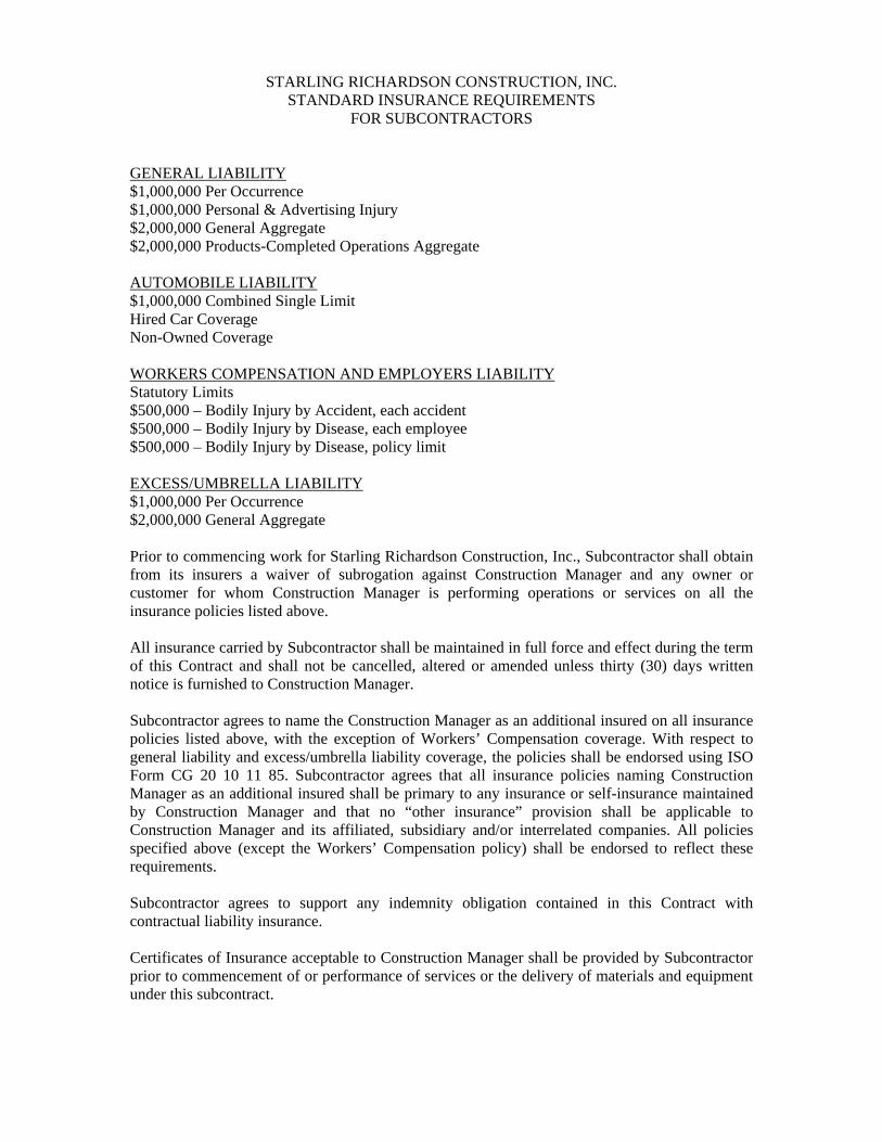
STARLING RICHARDSON CONSTRUCTION, INC. STANDARD INSURANCE REQUIREMENTS
FOR SUBCONTRACTORS
GENERAL LIABILITY $1,000,000 Per Occurrence $1,000,000 Personal & Advertising Injury $2,000,000 General Aggregate $2,000,000 Products-Completed Operations Aggregate AUTOMOBILE LIABILITY $1,000,000 Combined Single Limit Hired Car Coverage Non-Owned Coverage WORKERS COMPENSATION AND EMPLOYERS LIABILITY Statutory Limits $500,000 – Bodily Injury by Accident, each accident $500,000 – Bodily Injury by Disease, each employee $500,000 – Bodily Injury by Disease, policy limit EXCESS/UMBRELLA LIABILITY $1,000,000 Per Occurrence $2,000,000 General Aggregate Prior to commencing work for Starling Richardson Construction, Inc., Subcontractor shall obtain from its insurers a waiver of subrogation against Construction Manager and any owner or customer for whom Construction Manager is performing operations or services on all the insurance policies listed above. All insurance carried by Subcontractor shall be maintained in full force and effect during the term of this Contract and shall not be cancelled, altered or amended unless thirty (30) days written notice is furnished to Construction Manager. Subcontractor agrees to name the Construction Manager as an additional insured on all insurance policies listed above, with the exception of Workers’ Compensation coverage. With respect to general liability and excess/umbrella liability coverage, the policies shall be endorsed using ISO Form CG 20 10 11 85. Subcontractor agrees that all insurance policies naming Construction Manager as an additional insured shall be primary to any insurance or self-insurance maintained by Construction Manager and that no “other insurance” provision shall be applicable to Construction Manager and its affiliated, subsidiary and/or interrelated companies. All policies specified above (except the Workers’ Compensation policy) shall be endorsed to reflect these requirements. Subcontractor agrees to support any indemnity obligation contained in this Contract with contractual liability insurance. Certificates of Insurance acceptable to Construction Manager shall be provided by Subcontractor prior to commencement of or performance of services or the delivery of materials and equipment under this subcontract.
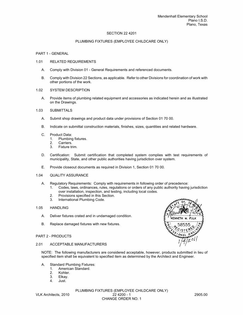
Mendenhall Elementary SchoolPlano I.S.D.
Plano, Texas
PLUMBING FIXTURES (EMPLOYEE CHILDCARE ONLY)VLK Architects, 2010 22 4200 - 1 2905.00
CHANGE ORDER NO. 1
SECTION 22 4201
PLUMBING FIXTURES (EMPLOYEE CHILDCARE ONLY)
PART 1 - GENERAL
1.01 RELATED REQUIREMENTS
A. Comply with Division 01 - General Requirements and referenced documents.
B. Comply with Division 22 Sections, as applicable. Refer to other Divisions for coordination of work withother portions of the work.
1.02 SYSTEM DESCRIPTION
A. Provide items of plumbing related equipment and accessories as indicated herein and as illustratedon the Drawings.
1.03 SUBMITTALS
A. Submit shop drawings and product data under provisions of Section 01 70 00.
B. Indicate on submittal construction materials, finishes, sizes, quantities and related hardware.
C. Product Data:1. Plumbing fixtures.2. Carriers.3. Fixture trim.
D. Certification: Submit certification that completed system complies with test requirements ofmunicipality, State, and other public authorities having jurisdiction over system.
E. Provide closeout documents as required in Division 1, Section 01 70 00.
1.04 QUALITY ASSURANCE
A. Regulatory Requirements: Comply with requirements in following order of precedence:1. Codes, laws, ordinances, rules, regulations or orders of any public authority having jurisdiction
over installation, inspection, and testing, including local codes.2. Provisions specified in this Section.3. International Plumbing Code.
1.05 HANDLING
A. Deliver fixtures crated and in undamaged condition.
B. Replace damaged fixtures with new fixtures.
PART 2 - PRODUCTS
2.01 ACCEPTABLE MANUFACTURERS
NOTE: The following manufacturers are considered acceptable, however, products submitted in lieu ofspecified item shall be equivalent to specified item as determined by the Architect and Engineer.
A. Standard Plumbing Fixtures:1. American Standard.2. Kohler.3. Elkay.4. Just.
Mendenhall Elementary SchoolPlano I.S.D.Plano, Texas
PLUMBING FIXTURES (EMPLOYEE CHILDCARE ONLY)VLK Architects, 2010 22 4200 - 2 2905.00
CHANGE ORDER NO. 1
5. Bradley.6. Acorn.7. Crane.
B. Carriers:1. Josam.
C. Seats:1. Church.2. Beneke.3. Olsonite.4. Centoco.
D. Faucets:1. Chicago.2. T&S Brass.
E. Flush Valves:1. Sloan Royal, or Zurn Aqua Vantage AV.
F. Stop Valve in Hot and Cold Supply Lines to Each Fixture:1. Chicago.2. McGuire.3. T&S Brass.4. Engineered Brass Company.
G. Stainless Steel Sinks:1. Elkay.2. Just.3. Metcraft.
H. Service Sinks:1. Fiat2. Stern Williams.3. American Standard.4. Haws.
I. Electric Water Coolers:1. Halsey-Taylor.2. Elkay.
J. Wash Fountains:1. Bradley
2.02 MATERIALS
A. Fittings: Chrome plated heavy cast brass.
B. Nipples: Extra heavy.
C. Plumbing Fixture Trim: Solid brass, including nuts and washers, handles, hold-down screws, valvebodies, swivel spouts, ferrules, sleeves, locknuts, and bushings.
D. Piping Connections from Shutoff or Stop Valve to Fixture: Chrome plated brass pipe or chrome platedcopper tubing.
E. Floor and Wall Escutcheons: Chromium plated with set screws.
F. Exposed Fixture Trimmings and Fittings: Chromium plated brass with polished, bright surfaces.
G. Flush Valves: Non-hold open type, without seat bumpers.
Mendenhall Elementary SchoolPlano I.S.D.
Plano, Texas
PLUMBING FIXTURES (EMPLOYEE CHILDCARE ONLY)VLK Architects, 2010 22 4200 - 3 2905.00
CHANGE ORDER NO. 1
H. Traps: Chrome cast brass adjustable P-traps with cleanout.
2.03 DESIGN AND FABRICATION
A. Plumbing fixture trims shall allow renewable operating units to be removed without detaching supplyfitting or faucet.
B. Fixtures, except water closets and urinals, shall have water supply above rim.
C. Equip fixtures with supply discharge below rims with backflow preventers.
D. Furnish angle stops, straight lock shield, loose-key pattern stops for supplies’ and install with fixtures.Supplies shall be rigid, unless noted otherwise.
E. Exposed traps and supply pipes for fixtures shall be connected to rough piping systems at wall.
F. All plumbing trim and fixtures indicated on Drawings as handicap shall meet the current requirementsof the Americans with Disabilities Act (ADA) and the Texas Accessibility Standards (TAS).
G. Faucets and bubblers shall be National Sanitation Foundation (NSF) Standard 61, Section 9,compliant and listed for residential/drinking water use as required by the Federal Clean Water acteffective January 1, 1997.
2.04 PLUMBING FIXTURE SCHEDULE
WC-1 - WATER CLOSET - WALL HUNG-FLUSH VALVE:1. Kohler K-4330 “Kingston”, wall hung siphon jet, elongated bowl, vitreous china with 1-1/2" top
spud.2. Flush valve: Sloan "Royal" "Optima" Automatic Model #111-ES-S-YBYC, fully automatic flush
valve with infrared sensor for "no hands" operation, 1.6 GPF, polished chrome, externallyadjustable, diaphragm type with 1" screwdriver angle stop, with sweat solder adaptor kit and castwall flange with set screw. Provide “Sentinel” 24 hour flush at all locations where TP-1 arelocated.
3. Transformer: Sloan #EL-154, 120 VAC primary, 24 VAC secondary transformer capable ofserving one to ten “Optima” flushometers.
4. Seat: Church 9400-SSC(5321.112) solid plastic, white, elongated, open front seat, less cover,combination check and self-sustaining hinges with stainless steel posts.
5. Support: Josam 12000 Series combination closet carrier and fitting. Provide back-to-back andsingle installations as job requires.
6. Mounting height (for student) as directed by Architect.
WC-2 - WATER CLOSET - WALL HUNG AUTOMATIC-FLUSH VALVE (HARD WIRED) -ELEMENTARY ADA/TAS COMPLIANT:1. Kohler K-4330 “Kingston”, wall hung siphon jet, elongated bowl, vitreous china with 1-1/2" top
spud.2. Flush valve: Sloan "Royal" "Optima" Automatic Model #111-ES-S-YBYC, fully automatic flush
valve with infrared sensor for "no hands" operation, 1.6 GPF, polished chrome, externallyadjustable, diaphragm type with 1" screwdriver angle stop, with sweat solder adaptor kit and castwall flange with set screw. Provide “Sentinel” 24 hour flush at all locations where TP-1 arelocated.
3. Transformer: Sloan #EL-154, 120 VAC primary, 24 VAC secondary transformer capable ofserving one to ten “Optima” flushometers.
4. Seat: Centoco Model 630-SST solid plastic, white, elongated, open front seat, less cover,combination check and self-sustaining hinges with stainless steel posts.
5. Support: Josam 16000 Series combination closet carrier and fitting. Provide back-to-back andsingle installations as job requires. “Critical” mounting height for elementary TAS compliance.
6. Mounting height (for student) as directed by Architect.
WC-3 - WATER CLOSET - WALL HUNG AUTOMATIC-FLUSH VALVE (HARD WIRED) - ADULTADA COMPLIANT:1. Kohler K-4330 “Kingston”, wall hung siphon jet, elongated bowl, vitreous china with 1-1/2" top
spud.
Mendenhall Elementary SchoolPlano I.S.D.Plano, Texas
PLUMBING FIXTURES (EMPLOYEE CHILDCARE ONLY)VLK Architects, 2010 22 4200 - 4 2905.00
CHANGE ORDER NO. 1
2. Flush valve: Sloan "Royal" "Optima" Automatic Model #111-ES-S-YBYC, fully automatic flushvalve with infrared sensor for "no hands" operation, 1.6 GPF, polished chrome, externallyadjustable, diaphragm type with 1" screwdriver angle stop, with sweat solder adaptor kit and castwall flange with set screw. Provide “Sentinel” 24 hour flush at all locations where TP-1 arelocated.
3. Transformer: Sloan #EL-154, 120 VAC primary, 24 VAC secondary transformer capable ofserving one to ten “Optima” flushometers.
4. Seat: Church 9400-SSC(5321.112) solid plastic, white, elongated, open front seat, less cover,combination check and self-sustaining hinges with stainless steel posts.
5. Support: Josam 12000 Series combination closet carrier and fitting. Provide back-to-back andsingle installations as job requires.
6. Mounting height (for adult) as directed by Architect.
WC-4 - WATER CLOSET - WALL HUNG-FLUSH VALVE (ELEMENTARY):1. Kohler K-4330 “Kingston”, wall hung siphon jet, elongated bowl, vitreous china with 1-1/2"
top spud.2. Flush valve: Sloan "Royal" 111-YBYC, 1.6 GPF, polished chrome, externally adjustable,
diaphragm type with 1" screwdriver angle stop, metal oscillating handle with sweat solderadaptor kit and cast wall flange with set screw.
3. "Critical" mounting height as directed by Architect, shall meet Texas AccessibilityStandards.
3. Seat: Centoco Model 630-SST, 3/4" thick, solid plastic, white, elongated, open front seat,less cover, combination check and self-sustaining hinges with stainless steel posts.
4. Josam 16000 Series, vertical only, non-adjustable combination closet carrier and fitting.
U-1 - URINAL - AUTOMATIC FLUSH VALVE - HANDICAP (HARD WIRED):1. Kohler K-5016-ET “Dexter”, wall hung, siphon jet, vitreous china with 3/4" top spud, 14-1/2"
elongated, flushing rim and 2" female outlet connection. 2. Flush valve: Sloan "Royal" "Optima" Automatic Model 186-1-ES-S-YBYC, fully automatic flush
valve with infrared sensor for "no hands" operation, 1 GPF, polished chrome, externallyadjustable, diaphragm type, with 3/4" screwdriver angle stop, with sweat solder adaptor kit andcast wall flange with set screw.
3. Transformer: Sloan #EL-154, 120 VAC primary, 24 VAC secondary transformer capable ofserving one to ten “Optima” flushometers.
4. Support: Josam 17800 Series floor mounted carrier with bearing plate. 5. Mounting height ADA/TAS compliant for primary user (i.e. student or adult).
U-2 - URINAL - HANDICAP:1. Same as Fixture Type "U-1" except mount for (student) handicapped.2. Mounting height as directed by Architect.
L-1 - LAVATORY - WALL HUNG - TEMPERED WATER ONLY - AUTOMATIC CONTROLS (HARD WIRED)
1. Same as Fixture Type L-2, except provide straight tail piece.
L-2 - LAVATORY - WALL HUNG - TEMPERED WATER ONLY - AUTOMATIC CONTROLS -HANDICAP (HARD WIRED):
1. Kohler K-1997, 20" x 18" vitreous china, 4" deep, "D" shaped bowl, self draining deck with sideand back splash, modified to comply with ADA front approach requirements, 4" faucet centers,punched for concealed arms.
2. Faucet/Strainer: Sloan ETF-600-B Sensor operated automatic lavatory faucet with 5" integralcast brass chrome plated spout, faucet and sensor housing, 2.2 gpm Vandalproof aerator, cable,connection box, solenoid valve, built-in check valves, in-line Y-strainer, and 120VAC to 24VACbox mount transformer EL-154. Provide Chicago 327-XCP perforated grid drain and wheelchairoffset tailpiece for ADA front approach. Provide 30 second run time.
3. Supplies: McGuire chrome riser supplies with loose key angle stops and chrome escutcheonplate with set screw.
4. Trap: McGuire 1-1/4" x 1-1/2", 17 gauge, chrome cast brass P-trap with cleanout plug andchrome escutcheon plate with set screw.
5. Support: Josam 17100 Series floor mounted carrier with concealed arms.
Mendenhall Elementary SchoolPlano I.S.D.
Plano, Texas
PLUMBING FIXTURES (EMPLOYEE CHILDCARE ONLY)VLK Architects, 2010 22 4200 - 5 2905.00
CHANGE ORDER NO. 1
6. Insulate exposed water supplies and drain piping with ADA approved insulation kit, equal toTruebro "Lav-Guard" Kit No. 102 and 105.
7. Mounting height as directed by Architect.
L-3 - LAVATORY - WALL HUNG - HOT AND COLD WATER - HANDICAP:1. Kohler K-1997, 20" x 18" vitreous china, 4" deep, "D" shaped bowl, self draining deck with side
and back splash, modified to comply with ADA front approach requirements, 8" faucet centers,punched for concealed arms.
2. Faucet/Strainer: Chicago 404-390-E12-VP, cast brass valve body, 8" centers, metal levervandal-resistant color coded chrome handles, quarter turn operating cartridge, ADA Compliant,vandalproof aerator with integral 2.2 GPM flow restrictor. Provide Chicago 327-XCP perforatedgrid drain and wheelchair offset tailpiece for ADA front approach access.
3. Supplies: McGuire chrome riser supplies with loose key angle stops and chrome escutcheonplate with set screw.
4. Trap: McGuire 1-1/4" x 1-1/2", 17 gauge, chrome cast brass P-trap with cleanout plug andchrome escutcheon plate with set screw.
5. Support: Josam 17100 Series floor mounted carrier with concealed arms.6. Insulate exposed water supplies and drain piping with ADA approved insulation kit, equal to
Truebro "Lav-Guard" Kit No. 102 and 105.7. Mounting height as directed by Architect.
L-4 - LAVATORY - COUNTERTOP - HOT AND COLD WATER - HANDICAP:1. Kohler K-2196-8 “Pennington”, 20" x 17", oval shaped, self-rimming, vitreous china, 8"
faucet centers.2. Faucet/Strainer: Chicago 404-636-E12-VP, cast brass valve body, 8" centers, metal lever
vandal-resistant color coded chrome handles, quarter turn operating cartridge, ADACompliant, vandalproof aerator with integral 2.2 GPM flow restrictor. Provide Chicago 327-XCP perforated grid drain and wheelchair offset tailpiece for ADA front approach access.
3. Supplies: McGuire chrome riser supplies with loose key angle stops and chromeescutcheon plate with set screw.
4. Trap: McGuire 1-1/4" x 1-1/2", 17 gauge, chrome cast brass P-trap with cleanout plug andchrome escutcheon plate with set screw.
5. Insulate exposed water supplies and drain piping with ADA approved insulation kit, equalto Truebro "Lav-Guard" Kit No. 102 and 105.
WF-1 - THREE (3) STATION MODULAR LAVATORY SYSTEM - ADA FRONT APPROACH:1. Bowl and spray head cover material for each station shall be constructed of NAHB Certified
Terreon, complying with ANSI Z124.3, Z124.6 and ANSI/ICPA SS-1-2001. Bowl finish shall bedecorative stone and bowl color shall be as selected by the architect.
2. Controls: Each hand washing station shall have an aerator served by an independent solenoidvalve and activated by a “Touch Time” sensing module with conical beam that does not exceedthe bowl perimeter. Each sensor shall have a 15 second operation.
3. Hot and cold water with 3/4" supply B.T.C., two 1/2" supplies with stops through wall and oneinch (1-1/2") P-trap to serve 1-1/2" drain stub out.
4. All supplies and waste connections shall be concealed within frame behind one heavy gaugestainless steel front access panel. Station shall be furnished with stainless steel supply hoseswith ball valve stops, 120V/24V plug in transformer, and thermostatic mixing valve.. Furnish onespare solenoid valve with each installed unit.
6. Acceptable Product: Bradley “Tri-Font” - MF2939-TT-TL
EWC-1 ELECTRIC WATER COOLER - HI/LO - WALL HUNG - ADA COMPLIANT1. Halsey-Taylor HAC-8FSBL-Q-ADA, barrier-free, ADA Compliant Bi-Level wall hung electric water
cooler with hermetically sealed air cooled condensing unit, self-closing anti-squirt flexi-guardbubbler volume regulator with front and side push-bars. Cooler shall deliver 8.0 GPH of 50Deg.F. water at 90 Deg.F. ambient and 80 Deg.F. inlet water. Provide stainless steel finish,unless designated otherwise by Architect. Furnish accessory apron when units are mounted onan exposed wall or necessary to provide the ADA mandatory underside clearance.
2. Support: Josam 17900 Series floor mounted carrier. 3. Supplies: McGuire chrome riser supply with wheel handle stop and chrome escutcheon plate
with set screw.

Mendenhall Elementary SchoolPlano I.S.D.Plano, Texas
PLUMBING FIXTURES (EMPLOYEE CHILDCARE ONLY)VLK Architects, 2010 22 4200 - 6 2905.00
CHANGE ORDER NO. 1
4. Trap: McGuire 1-1/4" x 1-1/2", 17 gauge, chrome cast brass P-trap with cleanout plug andchrome escutcheon plate with set screw.
5. Mounting height as directed by Architect.
EWC-2 - DRINKING FOUNTAIN - BARRIER FREE:1. Halsey-Taylor HAC-8FS, barrier-free wall hung drinking fountain with stainless steel receptor,
self-closing anti-squirt bubbler volume regulator, less cooler and compressor. Cabinet shall besatin stainless steel finish. Mount with bubbler as indicated on Architectural Drawings. Furnishaccessory apron when units are mounted on an exposed wall as necessary to provide the TASclearance.
2. Support: Josam 17900 Series floor mounted carrier.3. Supplies: McGuire chrome riser supply with wheel handle stop and chrome escutcheon plate with
set screw.4. Trap: McGuire 1-1/4" X 1-1/2", 17 gauge, chrome cast brass P-trap with cleanout plug and
chrome escutcheon plate with set screw.
DF-1 - DRINKING FOUNTAIN1. Elkay Model EDFP-19-C semi-recessed drinking fountain with stainless steel cabinet.2. Support: Josam 17900 Series floor mounted carrier.3. Supplies: McGuire chrome riser supply with loose-key stop and chrome escutcheon plate
with set screw.4. Trap: McGuire 1-1/4" x 1-1/2", 17 gauge, chrome cast brass P-Trap with cleanout plug and
chrome escutcheon plate with set screw.5. Mounting height as directed by Architect.
S-1 - CLASSROOM SINK (FRONT APPROACH):1. Elkay DRKADQ-2220-4, "Lustertone"16" x13-1/2" x 4" deep single compartment, self-rimming,
18 gauge, Type 302 stainless steel, sound deadened underside, faucet deck, 2-hole punchfaucet lever to sink front. One 3-1/2" drain openings off-center front-to-back, ADA compliant.
2. Faucet: Chicago #2302-CP "Marathon", cast brass valve body, rigid copper, 6" centers, ceramicdisc valving, swing spout, brass single lever vandal-resistant chrome handle, ADA compliant withvandalproof aerator.
3. Supplies: McGuire chrome riser supplies with wheel handle angle stops with chrome set screwescutcheon.
4. Tailpiece and Strainer: Dearborn Brass “Lucky 7 - L7T”stainless steel strainer drain with conicalstrainer basket and neoprene stopper, 1-1/2" o.d. off-set wheelchair chrome plated brasstailpiece.
5. Trap: McGuire 1-1/2" x 1-1/2", 17 gauge, chrome cast brass P-trap with cleanout plug, andchrome set screw escutcheon.
6. Insulate exposed water supplies and drain piping with ADA approved insulation kit, equal toTruebro "Lav-Guard" Kit No. 102 and 105.
7. Mounting height as directed by Architect.
S-2 - GENERAL PURPOSE SINK (FRONT APPROACH):1. Elkay LRAD-1918, single compartment, Type 302, 18 gauge stainless steel, 16" x 11-1/2" x 4"
deep, self-rimming, sound deadened underside, faucet deck, 3 hole punch, 3-1/2" drain opening,off-set front-to-back ADA Compliant.
2. Faucet: Chicago Model 201A-GN8A-E3-317, bottom mount, cast brass valve body, rigid copper,8" centers, gooseneck swing spout, #317, 4" wrist blade lever vandal-resistant color codedchrome handles, ADA compliant, with vandalproof aerator.
3. Supplies: McGuire chrome riser supplies with wheel handle angle stops with chrome escutcheonplate with set screw.
4. Tailpiece and Strainer: McGuire #151A stainless steel strainer drain with conical strainer basketand neoprene stopper, 1-1/2" o.d. off-set wheelchair chrome plated brass tailpiece.
5. Trap: McGuire 1-1/2" x 1-1/2", 17 gauge, chrome cast brass P-trap with cleanout plug, andchrome escutcheon plate with set screw.
6. Insulate exposed water supplies and drain piping with ADA approved insulation kit, equal toTruebro "Lav-Guard" Kit No. 102 and 105.
7. Mounting height as directed by Architect.
Mendenhall Elementary SchoolPlano I.S.D.
Plano, Texas
PLUMBING FIXTURES (EMPLOYEE CHILDCARE ONLY)VLK Architects, 2010 22 4200 - 7 2905.00
CHANGE ORDER NO. 1
S-3 - DOUBLE COMPARTMENT ART ROOM SINK1. Sink: Elkay LRAD-3321, 33" X 22-1/4" X 8" deep double compartment self-rimming 18 ga. Type
302 stainless steel sink with underside undercoated and 3-1/2" drain openings off-center front-to-back.
2. Faucet: Chicago #201-A-GN8A-E3-317CP, bottom mount, cast brass valve body, rigid copper,8" centers, gooseneck swing spout, metal lever vandal-resistant color coded chrome handles,ADA compliant, with vandalproof aerator.
3. Supplies: McGuire chrome riser supplies with loose-key angle stops and chrome escutcheonplate with set screw.
4. Tailpiece and Strainer: Elkay 35, chrome plated brass strainer drain, 1-1/2" o.d. chrome platedbrass tailpiece with conical strainer basket and neoprene stopper.
5. Plaster Interceptor: Josam 61030-30 Series cast aluminum, top access, fixture trap type, oneand one-half inch (1-1/2") threaded connections, basketed sediment bucket and removablestainless steel screen and acid-resisting interior finish.
S-3A - ART SINK (FRONT APPROACH):1. Elkay DRKADQ-2220-4, "Lustertone"16" x13-1/2" x 4" deep single compartment, self-rimming,
18 gauge, Type 302 stainless steel, sound deadened underside, faucet deck, 2-hole punchfaucet lever to sink front. One 3-1/2" drain openings off-center front-to-back, ADA compliant.
2. Faucet: Chicago #2302-CP "Marathon", cast brass valve body, rigid copper, 6" centers, ceramicdisc valving, swing spout, brass single lever vandal-resistant chrome handle, ADA compliant withvandalproof aerator.
3. Supplies: McGuire chrome riser supplies with wheel handle angle stops with chrome set screwescutcheon.
4. Tailpiece and Strainer: Dearborn Brass “Lucky 7 - L7T”stainless steel strainer drain with conicalstrainer basket and neoprene stopper, 1-1/2" o.d. off-set wheelchair chrome plated brasstailpiece.
5. Plaster Interceptor: Josam 61030-30 Series cast aluminum, top access, fixture trap type, oneand one-half inch (1-1/2") threaded connections, basketed sediment bucket and removablestainless steel screen and acid-resisting interior finish.
6. Insulate exposed water supplies and drain piping with ADA approved insulation kit, equal toTruebro "Lav-Guard" Kit No. 102 and 105.
7. Mounting height as directed by Architect.
S-4 - KITCHEN SINK (ADA FRONT APPROACH) WITH DISPOSER AND DISHWASHER:1. Elkay LRAD-2521 "Lustertone" 21" x 19" x 4" deep single compartment, self-rimming, 18 gauge,
Type 302 stainless steel, sound deadened underside, faucet deck, 5-hole punch (3 holes forfaucet and one hole each for vegetable spray and deck mounted brass chrome plated vacuumbreaker). Two 3-1/2" drain openings off-center front-to-back, ADA compliant.
2. Faucet: Chicago #201A GN8A-E3-317CP, "Marathon", cast brass valve body, rigid copper, 8"centers, ceramic disc valving, swing spout, brass single lever vandal-resistant chrome handle,ADA compliant with vandalproof aerator and vegetable spray.
3. Tailpiece and Strainer: Elkay LK-35 chrome plated brass strainer drain, 1-1/2" o.d. chromeplated brass tailpiece with conical strainer basket and neoprene stopper.
4. Continuous Waste: McGuire 1-1/2", 17 gauge chrome plated brass tubing for doublecompartment sink with disposer.
5. Trap: McGuire 1-1/2" x 1-1/2", 17 gauge, adjustable, chrome plated, cast brass P-trap withcleanout plug and chrome escutcheon plate with set screw with connection for disposer.
6. Supplies: McGuire chrome riser supplies with wheel handle angle stops with chrome escutcheonplate with set screw.
7. Brass chrome plated Vacuum Breaker: Shall be deck mounted and provided for dishwasher todischarge to the disposer, Sioux Chief Model 249.
8. Provide In-Sink-Erator, “Badger 1", 1/3 horsepower, 120 volt, single phase disposal. 9. Branch to connection 1/2" cold water with ball cock and union at ice maker connection.10. Branch to connection 1/2" hot water with ball cock and union at dishwasher.
MS-1 - MOP SINK:1. Stern Williams “Corlow” SBC-1700 terrazzo 24 inch by 24 inch floor mounted basin with 12 inch
high walls with 302 stainless steel cap cast integral on threshold. Drain shall be cast brass drainbody with stainless steel strainer, flat head, and slotted machine screws included.
2. Faucet: Chicago 897-RCJ KCP chrome plated, integral check stops, vacuum breaker, wallbracket pail hook, 3/4 inch hose thread, 8 inch center, arm handle and RCJ-KCP supply arm.
Mendenhall Elementary SchoolPlano I.S.D.Plano, Texas
PLUMBING FIXTURES (EMPLOYEE CHILDCARE ONLY)VLK Architects, 2010 22 4200 - 8 2905.00
CHANGE ORDER NO. 1
3. 5'-0" Hose with Hose Bracket: Stern-Williams T35.4. Splash Catcher Panel of 20 Gauge, 304 Stainless Steel: Stern Williams BP.5. Important: Float basin with wet mortar between slab and basin to distribute weight evenly and
prevent cracking of basin. Refer to installation recommendations by manufacturer.
ICB-1 - ICEMAKER BOX CONNECTION1. Guy Gray Model BIM 875, 20 gauge stainless steel box, hot dipped galvanized, and 1/2" angle
valve.
ACC-1 - AIR CONDITIONING CONDENSATE1. Guy Gray Model T-200-LY stainless steel box, 2" drain, less hose valves an supply connectors.2. Provide stainless steel access door and mounting frame with cylinder lock and key, sized to
cover box.3. Provide cut-off and trap primer inside box. Precision plumbing products, Model "Mini-Prime"
electronic trap primer Model MPB-200 -115V with brass adjusting screen.4. Mounting Height to be 6" AFF. Coordinate location with Architect and Finish Conditions.
PART 3 - EXECUTION
3.01 INSTALLATION
A. Install equipment in accordance with manufacturer's printed instructions and drawings.
B. Fasten fixtures secured to masonry walls or stud partitions with 1/4" brass toggle or through-bolts.
C. Anchor inserts flush with finished wall and conceal when fixtures are mounted.
D. Fixture Connections:1. Make connections between earthenware fixtures and flanges on soil pipe gas tight and watertight
with closet-setting compound or with neoprene gasket and seal.2. Do not use natural rubber gaskets or putty for these connections.3. Bolts shall be not less than 1/4" diameter and shall be equipped with chromium plated nuts and
washers.4. Set fixtures with outlet flanges required distance from floor or wall to make first class joint with
gasket and fixture used.
E. Fixture Mounting Heights: Refer to Drawings.
F. Provide stop valve in each hot and cold water supply line to each fixture.
3.02 KITCHEN EQUIPMENT; MILLWORK AND CASEWORK FIXTURES
A. Furnish and install all sinks and other plumbing items shown on furniture, unless shown otherwise.Provide detailed information to the supplier of such furniture as to required cut-outs and drillings, soas to permit proper coordination during fabrication. Provide local shut-off valves in all supplied to suchfurniture. Provide all waste connections, including drains, p-traps and other materials, using sanitarymaterials corresponding to piping system material in each case.
3.03 FIXTURES FURNISHED UNDER THIS DIVISION
A. Plumbing fixtures and equipment shall be set in place, leveled and connected as indicated on thedrawings. Use china caps to conceal mounting bolts, and grout between all vitreous china fixtures andfinished wall and floor surfaces with plaster of paris or portland cement.
B. Install wall hung water closets, lavatories, urinals, sinks and electric water coolers on carriers.
C. Do not install metal fittings until adjoining tile work has been acid- cleaned. The MechanicalContractor shall be responsible for the proper protection of fixtures after installation.
D. Connections to exposed plumbing fixtures shall be complete with chrome plated brass nipples, tubing,wall escutcheons, etc.
Mendenhall Elementary SchoolPlano I.S.D.
Plano, Texas
PLUMBING FIXTURES (EMPLOYEE CHILDCARE ONLY)VLK Architects, 2010 22 4200 - 9 2905.00
CHANGE ORDER NO. 1
3.04 ADJUSTING AND CLEANING
A. Prior to final acceptance of the work, Mechanical Contractor shall inspect all faucets, flush valves, stopvalves, etc., to determine whether they operate properly and discharge proper quantities of water.Connect any deficiencies to satisfaction of Architect's representative.
B. Thoroughly clean all plumbing fixtures, trim and accessories of all tape, adhesives and other foreignmaterials prior to final acceptance.
END OF SECTION
Mendenhall Elementary SchoolPlano I.S.D.
Plano, Texas
INSULATION (EMPLOYEE CHILDCARE ONLY)VLK Architects, 2010 23 0701 - 1 2905.00
CHANGE ORDER NO. 1
SECTION 23 0701
INSULATION (EMPLOYEE CHILDCARE ONLY)
PART 1 - GENERAL
1.01 RELATED REQUIREMENTS
A. Comply with Division 1 - General Requirements and referenced documents.
B. Comply with all other Division 23 Sections as applicable. Refer to other Divisions for coordination ofwork with other portions of work.
1.02 SYSTEM DESCRIPTION
A. Provide the systems of insulation which are specified for the control of heat transfer, sound control,and prevention of condensation.
B. Provide protective devices to prevent compression abrasion or puncture of the piping insulationsystems installed to include inserts, pipe shields, PVC jacketing and aluminum jacketing as specifiedherein.
C. Provide piping identification systems as specified in Section 23 05 53, Identification for HVACDuctwork, Equipment and Piping.
1.03 QUALITY ASSURANCE
A. The installation of all thermal insulation shall be performed by a single firm regularly engaged in theinsulation business, using skilled insulation mechanics and using insulation materials which are theproduct of reputable manufacturers. The application of the materials by the insulator shall be inaccordance with the published standards of the manufacturer of the materials, using any specialmaterials as required by these specifications and by those published standards.
B. Materials shall be manufactured by Schuller, Pittsburg Plate Glass, Owens-Corning, Foster,Certainteed, Mansville, or Knauf.
1.04 SUBMITTALS
A. Product Data: Submit manufacturer's descriptive literature and installation instructions to allow reviewof Materials and Methods to ensure complete compliance with specifications.
B. Shop Drawings: Submit materials to be used and method of application for each system in tabularform. General statements not specifically identifying means or methods to be used shall be cause forrejection. Include descriptive data and cut sheets on each type of insulation material, sealing method,adhesives used, insert types, shield sizes, and PVC or aluminum jacketing as specified.
1.05 PRODUCT HANDLING
A. Cover and protect material in transit and at site. Material not properly protected and stored and whichis damaged or defaced during construction shall and will be rejected.
B. Promptly replace all damaged, deteriorated or wet insulation materials.
C. Storage and protection of materials shall be in accordance with Section 23 05 00.
Mendenhall Elementary SchoolPlano I.S.D.Plano, Texas
INSULATION (EMPLOYEE CHILDCARE ONLY)VLK Architects, 2010 23 0701 - 2 2905.00
CHANGE ORDER NO. 1
PART 2 - PRODUCTS2.01 PIPING AND EQUIPMENT INSULATION MATERIALS
A. Waste, Drain and Miscellaneous Lines:1. The drain from each piece of Air Handling Equipment and rooftop unit condensate drain pan and
all refrigerant suction piping shall be insulated with foamed plastic, Armstrong Armaflex,Fiberglas O-C flexible, Certainteed-St.Gobain Ultra Foam or Schuller Aerotube slipped on whilethe piping is being fabricated, and with all joints, butt type, sealed using an adhesiverecommended by the manufacturer of the plastic. The insulation shall be continuous from thedrain opening in the Air Handling equipment (below the roof for the rooftop units) condensate panto the point of discharge with an open sight air gap over a drain. All formed plastic insulationshall meet ASTM E-84 requirements. Provide 1/ 2" thick insulation on condensate drains and1" thick insulation on refrigerant suction piping.
B. Plenum Safe Jacketing:1. Where non-plenum rated piping (such as PVC, CPVC, FRP, PE, PP, ABS, PVDF, etc.) is
installed in return air plenums cover all exposed portions of this piping with a plenum safejacketing, or wrap, system that is a factory manufactured and tested non-combustible barrier, toflame and smoke spread, designed to encapsulate non-rated or combustible items located inreturn air plenums, in accordance with the most recent additions of the International Building andMechanical Codes.
2. Plenum safe jacketing shall be covered with a light weight fiberglass reinforced foil scrim finishedhigh temperature rated insulation with an approximate density of 6 pounds per cubic foot.Jacketing shall have a Flame Spread and Smoke Developed rating of 0 for the unfaced blanketand be under 25 and 50 respectively for these items as tested in accordance with U.L. 723 andASTM E-84. Maximum Flame Spread in accordance with U.L.1887 shall be 0 feet. Maximumsmoke/optical density and Average Smoke per U.L.1887 testing shall not exceed 01 and 0respectively. U.L. 1887 test procedure is a modified tunnel test which provides test data forflame spread and smoke density using a single plastic pipe and a bundle of plastic pipes ofvarious sizes subjected to a fire test.
3. Thermal resistance of the barrier system shall be 4.2 as tested in accordance with ASTM C518.The Barrier System shall be able to withstand an operating temperature up to 2,300 Deg.F. andhave a melting point of no lower than 3,100 Deg.F.
4. Plenum safe jacketing shall be a minimum 1/2 inch thick and have at least one side covered witha foil skin which must face the outer, or exposed, side. All joints in each direction shall beoverlapped a minimum of one inch (1"). Jacket shall be secured tightly around the piping witheither stainless steel banding or stainless steel tie wire. Use stainless steel crimp clamps onbanding fasteners. Tie wires shall be secured using twist tensioning. Seal all cut edges withaluminum foil tape to ensure there is no exposed fiber.
5. Plenum safe jacketing shall be as manufactured by:a. Great Lakes Textiles, Inc. or approved equals by;b. 3M Corporation.c. Thermal Ceramics.d. FryeWrap by Unifrax.
2.02 DUCTWORK INSULATION MATERIALS
A. Duct Insulation - External: 1. Concealed (above ceilings) external duct insulation shall be glass fiber blanket-type insulation
of not less than 1 lb. per cu.ft. density with a factory applied flame-retardant vapor barrier facing. Apply to all supply and return air systems. Facing shall consist of a layer of aluminum foil,reinforced layer of glass fibers, and a layer of kraft paper all bonded together with fire-retardantand adhesive. Insulation, adhesives, and tapes shall be rated in accordance with U.L. 181A or181B. Minimum ductwrap insulation thickness shall be two inches (2") thick and be equal toCertainteed Type IV duct wrap.
2. All insulation systems shall meet the requirements of the 2006, or later, version of theInternational Energy Conservation Code, which requires a minimum installed R-value of 5.0 forconditioned, cooled or heated, and outside air system ductwork and plenums when locatedinside buildings or spaces. Increase insulation thicknesses as required to comply.
3. Water Vapor Permeance shall be no greater than 0.05 Perms per ASTM-E-96.
Mendenhall Elementary SchoolPlano I.S.D.
Plano, Texas
INSULATION (EMPLOYEE CHILDCARE ONLY)VLK Architects, 2010 23 0701 - 3 2905.00
CHANGE ORDER NO. 1
4. Fire Hazard Classification of installed duct insulation systems shall meet the requirements ofASTM-E-84; Flame Spread of 25, or less; Smoke Developed and Fuel Contributed of 50, or less.All insulation systems, adhesives, mastics, sealants, and tapes shall be U.L. rated for theapplication. All tapes used shall be acrylic based.
5. All external duct insulation shall be a regularly manufactured product of one of the following:a. Knauf.b. Owens Corning.c. Johns Manville.d. Certainteed.
B. Duct Insulation - Internal: 1. Internal duct insulation, liner, shall be in thicknesses as indicated herein, and be as specified
in Specification Section 23 30 00. Duct liner shall be one inch (1") thick and be used only on alltransfer air ductwork systems as specified elsewhere herein.
2. All duct liner shall be made of glass fiber coated with a bonded mat on the air stream side of theinsulation. Coating shall be neoprene based meeting the requirements of NFPA-90A and U.L.Standard 723. Insulation shall not be less than 1.5 lbs. per cu.ft. density, and have a K-value of0.28 per ASTM-C-177 at a mean temperature of 75 Deg.F.
3. All insulation systems shall meet the requirements of the 2006, or later, version of theInternational Energy Conservation Code, which requires a minimum installed R-value of 5.0 forconditioned, cooled or heated, supply and all outside air system ductwork and mixed air plenumswhen located inside buildings or spaces. Increase insulation thickness as required to comply.
4. Fire Hazard Classification of installed duct insulation systems shall meet the requirements ofASTM-E-84; Flame Spread of 25, or less; Smoke Developed and Fuel Contributed of 50, or less.
5. All insulation systems, adhesives, mastics, sealants, and tapes shall be U.L. rated for theapplication.
6. All duct liner shall be suitable for the air velocities to be encountered in each system, and shallgenerally be suitable for velocities of up to 6000 FPM.
7. Acceptable duct lining manufacturers shall be:a. Certainteed.b. Knauf.c. Owens Corning.d. Johns Manville.
PART 3 - EXECUTION
3.01 GENERAL
A. Apply insulation and pipe covering after all of the piping system to be insulated has been pressuretested, found to be completely tight (without leaks), and accepted as such. All insulated T-handles,blow-down valves, extended handles and caps should be installed prior to commencing with insulation.Verify that control, isolation, and balancing valves and any other piping specialty where a valve stemor test port extends beyond the normal pipe insulation thickness to be installed is installed pointedupward vertically. Thoroughly clean and dry all surfaces prior to being covered.
B. On glass fiber pipe covering with factory applied vapor barrier jacket, lap the jacket on the longitudinalseams and seal with vapor barrier lap adhesive equivalent to Foster 30-35. Tightly butt the ends andcover butt joints with a 4" wide band of vapor barrier jacket secured with the same adhesive.
C. Where jacketing systems are specified, use standard weight, PVC sheet rolls. Exercise care to locateseams in an inconspicuous place and apply all jacketing neatly, including that on valves and fittings.Unsightly work will be considered a justifiable basis for rejection. Adhere the jacketing in all cases witha lagging adhesive, Foster No. 30-36, Childers CP-50, or by other approved methods. Adhesives shallhave mold and mildew inhibitors.
D. All insulation shall be continuous through wall and ceiling openings and sleeves. Use exterior ductwrap insulation on the outside of smoke and fire damper sleeves. Create a secondary sleeve aroundthe primary sleeve to allow a complete insulation system as allowed by the local authority havingjursidiction.
Mendenhall Elementary SchoolPlano I.S.D.Plano, Texas
INSULATION (EMPLOYEE CHILDCARE ONLY)VLK Architects, 2010 23 0701 - 4 2905.00
CHANGE ORDER NO. 1
E. All insulation and accessories shall have composite (insulation, jacket and adhesive used to adherethe jacket to the insulation) fire and smoke hazard ratings as tested under procedure ASTM E-84,NFPA 255, and UL 723 not exceeding:
Flame SpreadSmoke DevelopedFuel Contributed
255050
F. Unsightly work shall be cause for rejection, including poor application of adhesives and coatingsbeyond the insulation which coats valves or other piping specialties.
G. Damage or Modification to Insulation: Where new insulation is disturbed or damaged during theprocess of installing other new materials, making new connections, etc., it shall be repaired orreplaced to return it to its original condition and appearance. Where lines are removed andconnections to insulated lines are capped, insulate those caps as well as repairing damagedinsulation. Materials shall match those presently installed in thickness, density, insulating value,jacketing, etc.
H. Miscellaneous Lines: Piping connected to chilled or hot water lines through which there might be fluidflow on occasions such as the lines connected to air vents, lines running to compression tanks, etc.shall be insulated as described for other piping in those systems.
I. Hanger and Support Locations: At the location of hangers or supports for pipes run above ground andfinished with a vapor seal insulation, provide rigid sections of cork, Foamglas, calcium silicate or highdensity polyurethane, at least the same thickness as the adjacent insulating material to adequatelysupport the pipe without compression of the insulating material and cover with a vapor seal that isbonded to the adjacent insulation as described for fittings in the lines. Where the insert has aninsulating value less than the adjacent pipe insulation the thickness of the insert shall be increasedto equal the insulating value of the adjacent pipe insulation. Wood inserts shall not be allowed.Hangers and supports for piping insulation to receive a vapor barrier shall be installed exterior to theinsulation.
J. Material Changes: Wherever there is a change in materials on lines that are vapor sealed, apply asuitable adhesive that is compatible with both materials, tapes, etc., as required to maintain the vaporbarrier.
K. The following describes materials, thickness and finishes for insulation on piping. In the following"exposed" shall mean any line or duct exposed below the finished ceiling and structure where noceiling is installed, in any room space, area, mechanical rooms, closets, and any line or duct runexterior to the building, including above the roof. "Concealed" shall mean any line or duct locatedabove ceilings, in furrings, in chases, in crawl spaces, and buried in direct contact with the soil.
L. In all "exposed" areas, up to 12'-0" above the finished floor, insulation shall receive a PVC jacketingsystem. Neatly install all insulation systems not receiving jacketing such that they are suitable forfinish painting.
M. All insulation materials and jacketing shall exhibit the following characteristics:1. Water sorption, per ASTM C 1104, shall be less than 0.02%.2. Linear shrinkage, per ASTM C 356, shall be negligible.3. Stress corrosion, per ASTM C 795, shall not cause corrosion.4. Corrosiveness, per ASTM C 665, shall not be any greater than sterile cotton.5. Resistance to fungi, mold and mildew and bacteria, per ASTM C 665, shall be rated as not
promoting growth of fungi and bacteria. Inhibitors shall be added to specified products to meetthese requirements.
3.02 DUCTWORK
A. Duct Insulation - Internal: Provide sound absorbing and thermal insulation to the interior surface ofthe following duct systems: All rectangular low pressure transfer ducts. All lined ductwork shall beincreased in size to maintain the clear inside (air stream) dimensions designated on the Drawings.
1. Duct liner shall be applied in accordance with the manufacturer's recommendations, with thecoated, or mat-faced, surface located away from the metal (exposed to air stream). It shall be
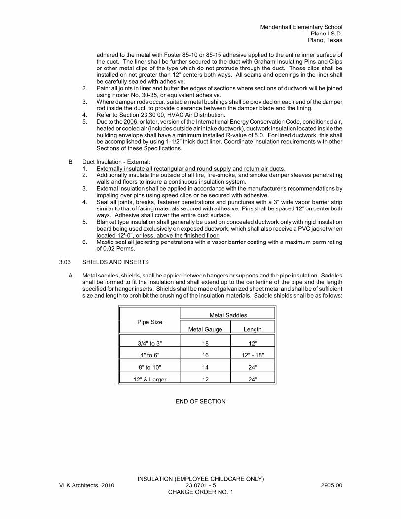
Mendenhall Elementary SchoolPlano I.S.D.
Plano, Texas
INSULATION (EMPLOYEE CHILDCARE ONLY)VLK Architects, 2010 23 0701 - 5 2905.00
CHANGE ORDER NO. 1
adhered to the metal with Foster 85-10 or 85-15 adhesive applied to the entire inner surface ofthe duct. The liner shall be further secured to the duct with Graham Insulating Pins and Clipsor other metal clips of the type which do not protrude through the duct. Those clips shall beinstalled on not greater than 12" centers both ways. All seams and openings in the liner shallbe carefully sealed with adhesive.
2. Paint all joints in liner and butter the edges of sections where sections of ductwork will be joinedusing Foster No. 30-35, or equivalent adhesive.
3. Where damper rods occur, suitable metal bushings shall be provided on each end of the damperrod inside the duct, to provide clearance between the damper blade and the lining.
4. Refer to Section 23 30 00, HVAC Air Distribution.5. Due to the 2006, or later, version of the International Energy Conservation Code, conditioned air,
heated or cooled air (includes outside air intake ductwork), ductwork insulation located inside thebuilding envelope shall have a minimum installed R-value of 5.0. For lined ductwork, this shallbe accomplished by using 1-1/2" thick duct liner. Coordinate insulation requirements with otherSections of these Specifications.
B. Duct Insulation - External: 1. Externally insulate all rectangular and round supply and return air ducts.2. Additionally insulate the outside of all fire, fire-smoke, and smoke damper sleeves penetrating
walls and floors to insure a continuous insulation system. 3. External insulation shall be applied in accordance with the manufacturer's recommendations by
impaling over pins using speed clips or be secured with adhesive. 4. Seal all joints, breaks, fastener penetrations and punctures with a 3" wide vapor barrier strip
similar to that of facing materials secured with adhesive. Pins shall be spaced 12" on center bothways. Adhesive shall cover the entire duct surface.
5. Blanket type insulation shall generally be used on concealed ductwork only with rigid insulationboard being used exclusively on exposed ductwork, which shall also receive a PVC jacket whenlocated 12'-0", or less, above the finished floor.
6. Mastic seal all jacketing penetrations with a vapor barrier coating with a maximum perm ratingof 0.02 Perms.
3.03 SHIELDS AND INSERTS
A. Metal saddles, shields, shall be applied between hangers or supports and the pipe insulation. Saddlesshall be formed to fit the insulation and shall extend up to the centerline of the pipe and the lengthspecified for hanger inserts. Shields shall be made of galvanized sheet metal and shall be of sufficientsize and length to prohibit the crushing of the insulation materials. Saddle shields shall be as follows:
Pipe SizeMetal Saddles
Metal Gauge Length
3/4" to 3" 18 12"
4" to 6" 16 12" - 18"
8" to 10" 14 24"
12" & Larger 12 24"
END OF SECTION
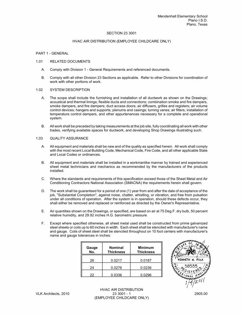
Mendenhall Elementary SchoolPlano I.S.D.
Plano, Texas
HVAC AIR DISTRIBUTIONVLK Architects, 2010 23 3001 - 1 2905.00
(EMPLOYEE CHILDCARE ONLY)
SECTION 23 3001
HVAC AIR DISTRIBUTION (EMPLOYEE CHILDCARE ONLY)
PART 1 - GENERAL
1.01 RELATED DOCUMENTS
A. Comply with Division 1 - General Requirements and referenced documents.
B. Comply with all other Division 23 Sections as applicable. Refer to other Divisions for coordination ofwork with other portions of work.
1.02 SYSTEM DESCRIPTION
A. The scope shall include the furnishing and installation of all ductwork as shown on the Drawings;acoustical and thermal linings; flexible ducts and connections; combination smoke and fire dampers,smoke dampers, and fire dampers; duct access doors; air diffusers, grilles and registers; air volumecontrol devices; hangers and supports; plenums and casings; turning vanes; air filters; installation oftemperature control dampers, and other appurtenances necessary for a complete and operationalsystem.
B. All work shall be preceded by taking measurements at the job site, fully coordinating all work with othertrades, verifying available spaces for ductwork, and developing Shop Drawings illustrating such.
1.03 QUALITY ASSURANCE
A. All equipment and materials shall be new and of the quality as specified herein. All work shall complywith the most recent Local Building Code, Mechanical Code, Fire Code, and all other applicable Stateand Local Codes or ordinances.
B. All equipment and materials shall be installed in a workmanlike manner by trained and experiencedsheet metal technicians and mechanics as recommended by the manufacturers of the productsinstalled.
C. Where the standards and requirements of this specification exceed those of the Sheet Metal and AirConditioning Contractors National Association (SMACNA) the requirements herein shall govern.
D. The work shall be guaranteed for a period of one (1) year from and after the date of acceptance of thejob, "Substantial Completion", against noise, chatter, whistling, or vibration, and free from pulsationunder all conditions of operation. After the system is in operation, should these defects occur, theyshall either be removed and replaced or reinforced as directed by the Owner's Representative.
E. Air quantities shown on the Drawings, or specified, are based on air at 75 Deg.F. dry bulb, 50 percentrelative humidity, and 29.92 inches H.G. barometric pressure.
F. Except where specified otherwise, all sheet metal used shall be constructed from prime galvanizedsteel sheets or coils up to 60 inches in width. Each sheet shall be stenciled with manufacturer's nameand gauge. Coils of sheet steel shall be stenciled throughout on 10 foot centers with manufacturer'sname and gauge tolerances in inches:
GaugeNo.
NominalThickness
MinimumThickness
26 0.0217 0.0187
24 0.0276 0.0236
22 0.0336 0.0296
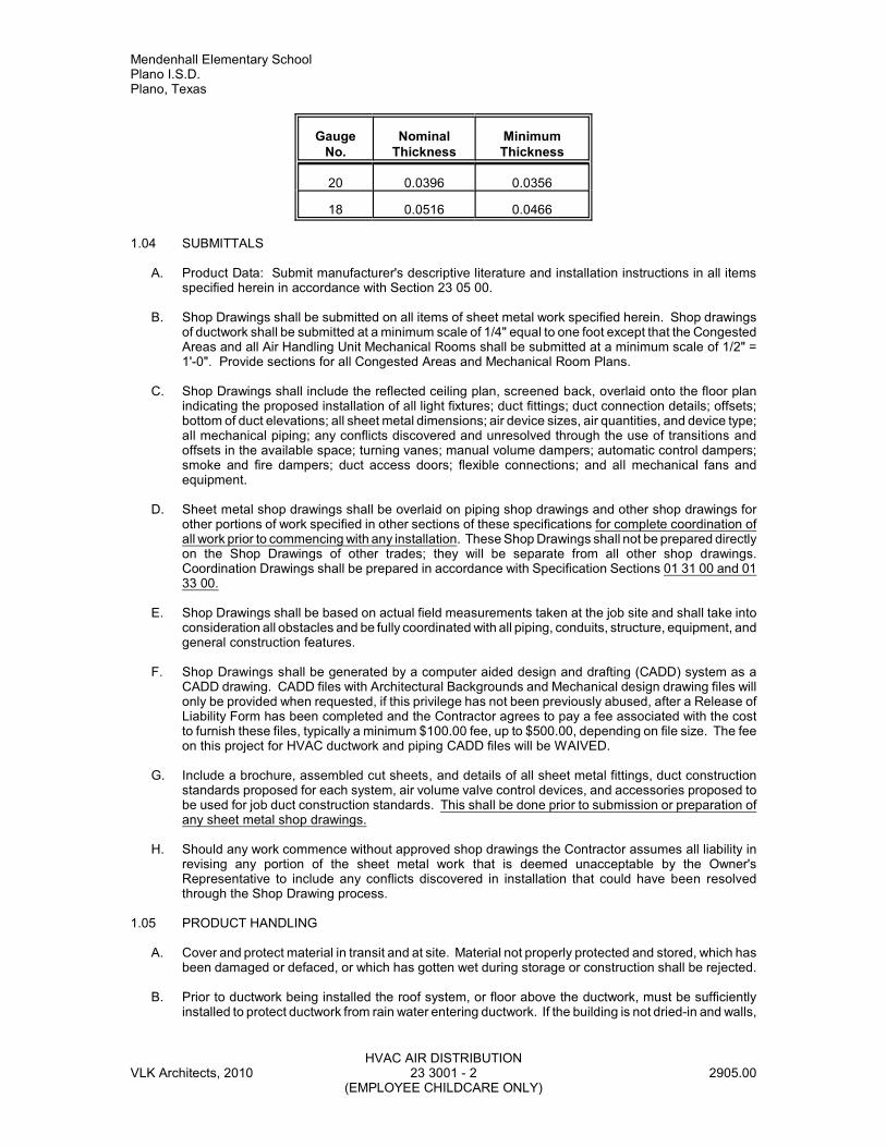
Mendenhall Elementary SchoolPlano I.S.D.Plano, Texas
GaugeNo.
NominalThickness
MinimumThickness
HVAC AIR DISTRIBUTIONVLK Architects, 2010 23 3001 - 2 2905.00
(EMPLOYEE CHILDCARE ONLY)
20 0.0396 0.0356
18 0.0516 0.0466
1.04 SUBMITTALS
A. Product Data: Submit manufacturer's descriptive literature and installation instructions in all itemsspecified herein in accordance with Section 23 05 00.
B. Shop Drawings shall be submitted on all items of sheet metal work specified herein. Shop drawingsof ductwork shall be submitted at a minimum scale of 1/4" equal to one foot except that the CongestedAreas and all Air Handling Unit Mechanical Rooms shall be submitted at a minimum scale of 1/2" =1'-0". Provide sections for all Congested Areas and Mechanical Room Plans.
C. Shop Drawings shall include the reflected ceiling plan, screened back, overlaid onto the floor planindicating the proposed installation of all light fixtures; duct fittings; duct connection details; offsets;bottom of duct elevations; all sheet metal dimensions; air device sizes, air quantities, and device type;all mechanical piping; any conflicts discovered and unresolved through the use of transitions andoffsets in the available space; turning vanes; manual volume dampers; automatic control dampers;smoke and fire dampers; duct access doors; flexible connections; and all mechanical fans andequipment.
D. Sheet metal shop drawings shall be overlaid on piping shop drawings and other shop drawings forother portions of work specified in other sections of these specifications for complete coordination ofall work prior to commencing with any installation. These Shop Drawings shall not be prepared directlyon the Shop Drawings of other trades; they will be separate from all other shop drawings.Coordination Drawings shall be prepared in accordance with Specification Sections 01 31 00 and 0133 00.
E. Shop Drawings shall be based on actual field measurements taken at the job site and shall take intoconsideration all obstacles and be fully coordinated with all piping, conduits, structure, equipment, andgeneral construction features.
F. Shop Drawings shall be generated by a computer aided design and drafting (CADD) system as aCADD drawing. CADD files with Architectural Backgrounds and Mechanical design drawing files willonly be provided when requested, if this privilege has not been previously abused, after a Release ofLiability Form has been completed and the Contractor agrees to pay a fee associated with the costto furnish these files, typically a minimum $100.00 fee, up to $500.00, depending on file size. The feeon this project for HVAC ductwork and piping CADD files will be WAIVED.
G. Include a brochure, assembled cut sheets, and details of all sheet metal fittings, duct constructionstandards proposed for each system, air volume valve control devices, and accessories proposed tobe used for job duct construction standards. This shall be done prior to submission or preparation ofany sheet metal shop drawings.
H. Should any work commence without approved shop drawings the Contractor assumes all liability inrevising any portion of the sheet metal work that is deemed unacceptable by the Owner'sRepresentative to include any conflicts discovered in installation that could have been resolvedthrough the Shop Drawing process.
1.05 PRODUCT HANDLING
A. Cover and protect material in transit and at site. Material not properly protected and stored, which hasbeen damaged or defaced, or which has gotten wet during storage or construction shall be rejected.
B. Prior to ductwork being installed the roof system, or floor above the ductwork, must be sufficientlyinstalled to protect ductwork from rain water entering ductwork. If the building is not dried-in and walls,
Mendenhall Elementary SchoolPlano I.S.D.
Plano, Texas
HVAC AIR DISTRIBUTIONVLK Architects, 2010 23 3001 - 3 2905.00
(EMPLOYEE CHILDCARE ONLY)
windows, etc., are not completed, then cover all openings in ducts with securely fastened heavy duty,minimum three (3) mil thick, plastic to protect from rain damage.
C. Storage and protection of materials shall be in accordance with Section 23 05 00.
PART 2 - PRODUCTS
2.01 DUCTWORK
A. General:1. All ductwork shown on the Drawings, specified or required for the heating, ventilating, and air
conditioning systems, shall be constructed and erected in a first-class workmanlike manner bytrained and skilled sheet metal workers.
2. All ducts shall be erected in the general locations shown on the Drawings, but must conform toall structural and finish conditions of the building. Before fabricating any ductwork, Contractorshall check the physical conditions of the job site, and shall make all necessary changes in crosssections, offsets, etc., whether they are specifically indicated or not.
3. Before starting shop drawings or fabrication of any ductwork, the Contractor must have anapproved reflected ceiling plan with which he can coordinate location of air outlets, lights, tilepatterns, etc.
4. The sizes of ducts indicated on the Drawings are the required net internal air stream dimensions,and where ducts are lined, the sheet metal sizes shall be increased three inches (3") in bothdimensions to accommodate the linings (1-1/2" thick lining, unless indicated otherwise). Assumeall rectangular ducts are lined unless noted otherwise.
5. Ductwork shall be classified, for construction standards, as follows:a. All constant volume ductwork (supply and return) served by packaged rooftop units, split
direct expansion (supply, return and outside air) A/C units, and all transfer and exhaust airducts shall be constructed to meet one inch (1") W.G. standards.
6. Except as noted otherwise, ducts, plenums, and casings shall be constructed of new lock formingquality galvanized prime grade steel sheets. The gauges of metal to be used, duct constructiondetails, and the construction and bracing of joints shall be in accordance with the latest editionof the published standards of the ASHRAE Handbook or in accordance with the latest editionsof Sheet Metal and Air Conditioning Contractors' National Association (SMACNA) "DuctConstruction Standards Manual, Metal and Flexible".
7. Plenum chambers shall be constructed of 18 gauge sheets thoroughly braced with 1-1/2 inchangle irons. All duct panels in rectangular galvanized steel ducts which are 12 inches and widerand which are not lined shall be crossbroken.
8. Make square elbows where shown or required, with factory fabricated double thickness turningvanes. Job fabricated vanes will not be acceptable. Except as otherwise specified or indicatedon the drawings, make all other changes in direction with rounded elbows having a centerlineradius equal to 1-1/2 times the width of the duct in the plane of the bend.
9. Make transformations in duct shape or dimension with gradual slopes on all sides. Normally,make increases in dimension in the direction of air flow, with a maximum slope of one inch (1")in seven inches (7") on any side. Where conditions prevent the normal slope specified above,a maximum slope of one inch (1") in four inches (4") will be allowed only where conditionsnecessitate.
10. Where a transition must be made with less slope than that noted above, install single thicknessguide vanes to insure proper air flow, and to minimize air pressure drop. Transitions that requireless slope than that noted above shall be noted on Shop Drawings, and require review andapproval by the Engineer prior to installation.
11. Ducts shall be routed in conjunction with all types of pipes, electrical conduits, ceiling hangers,etc., so as to avoid interferences insofar as possible. When duct penetrations are unavoidable,provide streamline-shaped sleeves around such material penetrations, made airtight at ductsurfaces, except that such sleeves are not required at tie rods. When the Contractor believessuch penetrations are unavoidable, notify the Owner's Representative for approval prior tocommencing with such work. Otherwise all such penetrations are not expected to occur and arenot allowed. Such penetrations will not be allowed for the convenience of, or lack of coordinationby, the Contractor. Where obstructions necessitate, are approved by the Owner'sRepresentative, and are of a size exceeding 10% of the total duct area, the duct shall betransformed to maintain the same original duct area.
Mendenhall Elementary SchoolPlano I.S.D.Plano, Texas
HVAC AIR DISTRIBUTIONVLK Architects, 2010 23 3001 - 4 2905.00
(EMPLOYEE CHILDCARE ONLY)
12. Where each duct passes through a fan room wall, it shall be wrapped with not less than 1/2"thick closed cell neoprene tightly fitted to the outer surface of the duct all around and sealed.In lieu of this method, completely fill the annular space between the duct and penetration bypacking with fibrous insulation and seal the perimeter of the penetration around the duct, on bothsides of the penetration, with a flexible non-hardening sealant, to be fire rated when applicable.
13. All outlets or grilles in ceilings shall be supported rigidly from ceiling construction with suitableadapters or bucks installed as necessary and as shown to insure outlets and grilles will beaccurately trued up with ceiling.
14. Ductwork shall be fabricated in a manner to prevent the seam or joints being cut for theinstallation of grilles or diffusers.
15. All sheet metal ductwork shall be securely hung from the building construction. All ducts shallbe hung adjacent to the seam in the duct and shall be secured in a suitable manner to both theduct and the building construction. All vertical riser ducts shall be supported at each floor withangle iron secured to the ducts and set on the structure members. These angles shall be thesame size as specified for bracing.
16. All holes in ducts for damper rods and other necessary devices shall be either drilled or machinepunched (not pin punched), and shall not be any larger than necessary. All duct openings shallbe provided with sheet metal caps if the openings are to be left unconnected for any length oftime. All panels of uninsulated ducts twelve inches (12") and larger shall be crossbroken. Ingeneral, sheet metal screws shall not be used in duct construction unless the point of the screwis in the air stream unless specifically indicated otherwise elsewhere herein.
17. Manual dampers shall be installed as shown and as required to afford complete control of theair flow in the various duct systems. In rectangular supply ducts, a splitter damper shall beinstalled at each point where a branch is taken off and additional volume dampers shall beinstalled where shown or required to achieve the final air balance. No splitter dampers shall beinstalled in medium pressure ductwork, unless specifically shown on Drawings.
18. Splitter dampers and volume dampers of the "butterfly" type, installed in rectangular ducts, shallbe constructed of 16 gauge galvanized steel riveted or welded to square operating rods.Dampers shall have brass, bronze, or approved plastic bearings. The length of any splitterdamper blade shall be 1-1/2 times the width of the smaller split in the duct, but shall be not lessthan twelve inches (12"). Where splitter dampers exceed 12 inches in height two (2) pull rodsshall be used. Splitter dampers 12 inches (12") in height or less shall have one (1) pull rod.
19. Butterfly damper blades in round ducts shall be the full width of the duct in which they areinstalled. Dampers shall be constructed of a minimum 22 gauge metal. Dampers over twelveinches (12") in diameter shall be constructed of 20 gauge metal, have a continuous rod with endbearings opposite the damper handle, and a quadrant type locking handle.
20. The operating rods of all dampers shall be fitted with Young Regulators and the operating headshall be securely fastened in place so as to be accessible in the finished building unless shownotherwise. Operators shall be attached to duct where regulator occurs above a lay-in ceiling.Use a Ventlock No. 555 locking quadrant on accessible concealed splitter dampers. Wheredampers occur above or behind plaster or other inaccessible ceilings, walls, chases or furrings,the regulator shall be the concealed type with adjustable cover plate equal to Young RegulatorCompany Type 315 with maximum 2-1/2" diameter cover plate and required accessories. YoungRegulator bearings shall also be provided on the opposite end of each operating rod.
21. Behind each ceiling supply outlet, provide and install a turning vane or approved equalizing grid,where noted or scheduled. Where adjustable air pick-ups are indicated at points branch ductsmeet trunk ducts, they shall be Titus AG-45 or approved equal with operator adjustable from theduct exterior.
22. Rectangular opposed blade volume dampers shall be as manufactured by American Warmingand Ventilating or Ruskin. Blades shall not exceed 48 inches in length or twelve inches (12") inwidth, and shall be the opposed interlocking blade type. The blades shall be of not less than No.16 gauge steel supported on one-half inch (1/2") diameter rustproofed axles. Axle bearings shallbe the self-lubricating ferrule type.
B. Low Pressure Ductwork:1. Rectangular low pressure ducts, for systems designated to be operating at up to one (1) inches
W.G., shall be constructed of the following medium gauges:
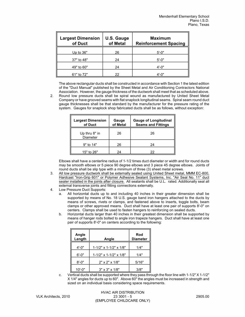
Mendenhall Elementary SchoolPlano I.S.D.
Plano, Texas
HVAC AIR DISTRIBUTIONVLK Architects, 2010 23 3001 - 5 2905.00
(EMPLOYEE CHILDCARE ONLY)
Largest Dimensionof Duct
U.S. Gaugeof Metal
MaximumReinforcement Spacing
Up to 36" 26 5'-0"
37" to 48" 24 5'-0"
49" to 60" 24 4'-0"
61" to 72" 22 4'-0"
The above rectangular ducts shall be constructed in accordance with Section 1 the latest editionof the "Duct Manual" published by the Sheet Metal and Air Conditioning Contractors NationalAssociation. However, the gauge thickness of the ductwork shall meet that as scheduled above.
2. Round low pressure ducts shall be spiral wound as manufactured by United Sheet MetalCompany or have grooved seams with flat snaplock longitudinal seams. Spiral seam round ductgauge thicknesses shall be that standard by the manufacturer for the pressure rating of thesystem. Gauges for snaplock shop fabricated ducts shall be as follows, without exception:
Largest Dimensionof Duct
Gaugeof Metal
Gauge of LongitudinalSeams and Fittings
Up thru 8" inDiameter
26 26
9" to 14" 26 24
15" to 26" 24 22
Elbows shall have a centerline radius of 1-1/2 times duct diameter or width and for round ductsmay be smooth elbows or 5 piece 90 degree elbows and 3 piece 45 degree elbows. Joints ofround ducts shall be slip type with a minimum of three (3) sheet metal screws.
3. All low pressure ductwork shall be externally sealed using United Sheet metal, MMM EC-800,Hardcast "Iron-Grip 601" or Polymer Adhesive Sealant Systems, Inc. "Air Seal No. 11" ductsealer installed in the joints after closure. All sealants shall be U.L. rated. Additionally seal allexternal transverse joints and fitting connections externally.
4. Low Pressure Duct Supports:a. All horizontal ducts up to and including 40 inches in their greater dimension shall be
supported by means of No. 18 U.S. gauge band iron hangers attached to the ducts bymeans of screws, rivets or clamps, and fastened above to inserts, toggle bolts, beamclamps or other approved means. Duct shall have at least one pair of supports 8'-0" oncenters. Clamps shall be used to fasten hangers to reinforcing on sealed ducts.
b. Horizontal ducts larger than 40 inches in their greatest dimension shall be supported bymeans of hanger rods bolted to angle iron trapeze hangers. Duct shall have at least onepair of supports 8'-0" on centers according to the following:
AngleLength Angle
RodDiameter
4'-0" 1-1/2" x 1-1/2" x 1/8" 1/4"
6'-0" 1-1/2" x 1-1/2" x 1/8" 1/4"
8'-0" 2" x 2" x 1/8" 5/16"
10'-0" 3" x 3" x 1/8" 3/8"
c. Vertical ducts shall be supported where they pass through the floor line with 1-1/2" X 1-1/2"X 1/4" angles for ducts up to 60". Above 60" the angles must be increased in strength andsized on an individual basis considering space requirements.
Mendenhall Elementary SchoolPlano I.S.D.Plano, Texas
HVAC AIR DISTRIBUTIONVLK Architects, 2010 23 3001 - 6 2905.00
(EMPLOYEE CHILDCARE ONLY)
5. All low pressure ductwork shall be reinforced to maintain a maximum reinforcement spacing asscheduled with the rigidity classification as needed to meet the specification constructionstandard. Reinforcement spacing shall be reduced as required to meet the constructionstandard specified using the gauge thickness scheduled.
C. Round Flexible Insulated Ductwork:1. All round flexible insulated ducts, low and high pressure type, shall be factory fabricated and
insulated as manufactured by Flexible Technologies or Flexmaster USA, Inc. Flexible ducts shallbe equal to Thermaflex factory insulated type "MKE-10" or Flexmaster “Type 3M”.
2. Flexible duct thermal conductance shall be not more than 0.23 BTU/Hour/Square Foot/Deg.F.at 75 Deg.F. mean temperature. Flexible duct insulation shall be a minimum nominal 2.0" inthickness with a minimum 0.75 lb. density. The completed duct assembly shall have a minimumR-value of 5.0. To verify compliance with the 2006, or later, version of the International EnergyConservation Code, the minimum R-value of 5.0 will need to be documented to allow fieldverification of compliance with this requirement. Where flexible duct having an R-value of lessthan 5.0 is the only type available from a manufacturer, then the flexible insulated duct will eitherbe special ordered to be double wrapped, or increased in thickness as needed to comply, at thefactory or field insulate this duct system with a minimum 1-1/ 2 inch thick duct wrap, 0.75 lb.density, as specified in Section 23 07 00.
3. Flexible ducts shall be U.L. Listed in accordance with U.L. 181 as a Class I insulated air duct,and shall comply with NFPA Standard 90A and 90B. Flexible ducts shall have a maximum flamespread of 25 and maximum smoke developed rating of 50.
4. Flexible ducts shall be suitable for operating temperatures of -20 up to 250 Deg.F.5. Flexible ducts shall be suitable for negative pressures of minus one inch W.G. in sizes up to 16"
in diameter; and positive pressures up to 10 inches W.G. for sizes up to 16" in diameter.Maximum operating duct velocity rating shall be a minimum of 4,000 feet per minute.
6. Maximum vapor transmission rating shall be 0.05 Perms as rated in accordance with ASTM-E-96.
7. Unless otherwise noted, the maximum length of flexible duct shall be limited to five feet (5').8. Securement of flexible ducts to air devices shall consist of sliding the duct onto the air device
collar or connector and securing it with plenum rated nylon or teflon panduit band on the innerliner which shall be U.L rated for the application. Fold insulated outer vapor barrier jacket linerover the first band and secure with a second plenum rated panduit band. Make connectionvaportight with a vapor barrier seal using polyester reinforced aluminized duct tape that is twoinches (2") wide, wrapped 2 times around the duct, or by the use of a fiberglass mesh wrappedin a similar fashion and coated with a Foster’s vapor seal adhesive. No cloth backed duct tapeis allowed. All fasteners, adhesives, and duct tape used shall be U.L.rated for the application.All duct tapes used shall be acrylic based.
2.02 FIRE, SMOKE, AND COMBINATION SMOKE-FIRE DAMPERS
A. Contractor shall furnish and install fire, smoke, and combination smoke-fire dampers in air passages,openings, and ductwork wherever shown on the Drawings, and as required by the local authoritieshaving jurisdiction. Installations shall be in accordance with all applicable NFPA standards and theSMACNA Duct Manual. All dampers shall carry the U.L. Label and shall be installed such as toconform to conditions under which the U.L. Label was granted. All dampers shall be constructed andtested in accordance with the latest edition of U.L. Safety Standards 555 or 555S, as applicable.Provide sleeves, typically 12" in length minimum, for all dampers as required for the installationconditions encountered.
B. Smoke dampers shall be designed for vertical or horizontal applications as encountered in accordancewith NFPA 90A and meet the latest requirements of UL 555 S. Smoke dampers shall be installed in,or adjacent to, the smoke barrier; but in no case, more than 24 inches from the smoke barrier. Smokedampers shall be a Ruskin Model SD35, 36, 37, or SDRS25 as applicable for the application. Framesshall be made of 16 gauge single piece galvanized steel hat shaped channel frames. Blades shall be6" wide galvanized steel and be the triple V-groove or air foil type. Provide stainless steel jamb seals,silicone edge type blade seals where required for the classification, stainless steel sleeve bearingsand linkages concealed in the frame. Leakage Class shall be Class 1, 2, or 3, as required, to meetthe requirements specified elsewhere herein. Provide compatible electric actuator on all dampers,factory installed.
Mendenhall Elementary SchoolPlano I.S.D.
Plano, Texas
HVAC AIR DISTRIBUTIONVLK Architects, 2010 23 3001 - 7 2905.00
(EMPLOYEE CHILDCARE ONLY)
C. Insulated all metal access panels, secured with sash locks, shall be installed to service all fire, smoke,and combination smoke-fire dampers. Access panels shall be identified with "FIRE DAMPER",“SMOKE DAMPER”, or "SMOKE-FIRE DAMPER" stenciled thereon in a visible or conspicuouslocation. Removable flexible duct shall not be permitted as a means of damper access. Access shallbe direct and shall not be obstructed by turning vanes or other duct accessories.
D. General Requirements:1. For ductmate connections at fire, smoke, or combination smoke-fire dampers, do not use screw
fasteners.2. Use four inch (4") draw band connections at round duct fire damper connections.3. Use blade dampers when the blade width exceeds 12 inches. 4. Install vertical or horizontal mount dampers suitable for the application. 5. Dampers shall be suitable for the maximum air system operating pressures expected to be
encountered. Medium pressure ductwork is expected to operate at up to six inches (6") W.G.6. Use multi-section dampers where damper size openings are larger than single section maximum
sizes. 7. Fire, smoke and combination smoke-fire dampers shall be sized to provide for 100 percent of
the ductwork size (minimum 95% free area) indicated on the Drawings through each damper.8. Provide 165 Deg.F. rated fusible links for fire dampers.
E. Acceptable Manufacturers:1. Ruskin, or approved equals by:2. Greenheck, or3. Nailor, or4. Prefco, or5. National Controlled Air (N.C.A.), or6. Air Balance, or7. Pottoroff.
2.03 FLEXIBLE CONNECTIONS
A. Where ducts connect to fans, including roof exhausters, flexible connectors shall be made that are fire-resistant, (up to 200 Deg. F.), waterproof, mildew-resistant and essentially airtight, and shall weighapproximately thirty ounces (30 oz.) per square yard.
B. There shall be a minimum of one-half inch (1/2") slack in these connections, and a minimum of twoand one-half inches (2-1/2") distance between the edges of the ducts for a total of three inches (3").There shall also be a minimum of one inch (1") of slack for each inch of external static pressure onthe fan system for medium pressure systems.
C. Acceptable Manufacturers:1. Vent Fabrics "Ventglas", or approved equals by:2. Duro-Dyne.
2.04 ACCESS DOORS
A. Furnish and install hinged, low leakage access doors in ductwork or plenums to provide access to allfire, smoke and combination fire - smoke dampers, mixed air plenums, automatic dampers, coils,filters, and elsewhere as detailed on the Drawings.
B. Where the ducts are insulated, the access doors shall be double skin doors with a minimum one inch(1") of insulation in the door. The insulation shall have a minimum R-value of 5.0. Increase thethickness of the insulation as needed to comply. Where the access door is installed in non-insulatedductwork the access door shall be unlined sheet metal of the same gauge thickness as the duct.
C. In no case shall access doors be smaller than eight (8") by eight inches (8"). Access doors shall besized to permit testing or servicing of duct mounted components, such as, for coil cleaning, installationof control devices, resetting of fusible links, filter replacement, etc., as applicable and suitable for theapplication.
D. Where duct access doors are above a suspended, normally non-readily accessible ceiling, such asplaster, gypboard or spline type ceilings, Contractor, under this Section of Specifications, shall be
Mendenhall Elementary SchoolPlano I.S.D.Plano, Texas
HVAC AIR DISTRIBUTIONVLK Architects, 2010 23 3001 - 8 2905.00
(EMPLOYEE CHILDCARE ONLY)
responsible for the proper location, and furnishing of, ceiling access doors, or panels, to make ductaccess doors easily accessed through the ceiling system. Ceiling access doors, or panels, shall berated, where applicable, to match the fire rating of the ceiling system penetrated. Ceiling access doors,or panels, shall be installed under other Sections of these Specifications. Ceiling access doors, orpanels, shall be centered directly beneath duct access doors or immediately adjacent thereto whenduct access is through the side of the duct.
E. All access doors shall be fully double gasketed, door to frame and frame to duct, and include a sashtype or compression latches for sizes under eighteen inches (18") by eighteen inches (18"). Use one(1) sash type latch per twelve inches (12") of height or width. Access doors 18" x 18" and larger shallhave quarter turn handle latches; Provide one handle per 24" section, height or width, of door. As anexample, provide two (2) handle type latches for a 48" tall access door.
F. Provide a minimum of two (2) heavy loose pin hinges for each access door unless indicated otherwiseherein. Piano style hinges will be an allowed substitute.
G. Where the installation conditions prohibit suitable access with hinged access doors, then non-hingedaccess doors may be used in conjunction with a corrosion resistant cable or chain, of suitable length,attached to the access door and duct.
H. For duct systems constructed to 2 inches W.G standards, or less, provide standard access doorsmeeting all requirements specified herein, which have a tested air leakage rating of less than 4.0 CFMat a test pressure of 2 inches W.G., and as manufactured by:1. Ventlok with hinges and No. 90 or No. 99 latches (less than 18" x 18"), or No. 100 or No. 140
latches (18" x 18" and larger), as applicable, or approved equals by:2. Ductmate, or3. Duro Dyne DDIAD-0806, or4. NCA Manufacturing ADH-T-1, or5. Pottorff CAD or WAD, or6. Nailor 08SH with HP Seal, or 0890, or7. Cesco Products HDG, or8. Ward Sandwich Style Access Doors, DSA or DDA, for round ductwork.
2.05 DUCT LINER
A. Only rectangular transfer air ducts shown on the Drawings; shall be lined with Fiberglass mat facedduct liner in the thicknesses.
B. The liner insulation system shall be one inch (1.0") in thickness.
C. All ductwork systems are required to meet the 2006, or later version, of the International EnergyConservation Code.
D. All duct liners shall comply with NFPA 90A and 90B and ASTM C 1071, Type I, for ducts and Type IIfor plenums (rigid liner). Liner shall consist of flexible, matt faced insulation made of inorganic glassfibers bonded by a thermosetting resin with an encapsulant edge coating, and shall be a rotary styleduct liner product with a water repellant ingredient on the mat face to help keep moisture frompenetrating the air stream surface. Other technical requirements shall include:1. Be suitable for temperatures up to 250 Deg.F. per ASTM C 411.2. Be suitable for air velocities up to 6,000 FPM per ASTM C 1071 for Type I products and 5000
FPM for Type II products.3. Water vapor sorption shall be less than 3% by weight per ASTM C 1104.4. Air stream surface mat facing shall be tested with an EPA registered anti-microbial agent to aid
in the prevention of fungal and bacterial growth. Mat face, as treated, shall not support thegrowth of mold, fungi, or bacteria per ASTM C 1338, ASTM G 21 and ASTM G 22.
5. Does not exceed a Flame Spread of 25 and Smoke Developed and Fuel Contributed of 50 perASTM E 84, NFPA 225, and UL 723.
6. Conductance of 0.24 (R-value of 4.2) for a 1.5 PCF or 2.0 PCF duct liner at a 75 Deg.F. meantemperature per ASTM C177 for a one inch (1") thick product.
7. Greenguard Compliant (Greenguard Environmental Institute).8. Noise Reduction Coefficient (NRC) of 0.70 or higher for a one inch (1") thick product and 0.80
for a two inch (2") thick product per ASTM C 423, type A mounting.
Mendenhall Elementary SchoolPlano I.S.D.
Plano, Texas
HVAC AIR DISTRIBUTIONVLK Architects, 2010 23 3001 - 9 2905.00
(EMPLOYEE CHILDCARE ONLY)
E. All duct liners shall be able to be cleaned in accordance with the North American InsulationManufacturers Association (NAIMA) “Cleaning Fibrous Glass Insulated Air Duct SystemsRecommended Practices”.
F. Liner shall be applied to the inside of rectangular ducts and plenums with fire-resistant adhesive, 3MNo. 37, or equal, complying with ASTM C 916, completely coating the clean sheet metal. All joints inthe insulation shall be “buttered” and firmly butted tightly to the adjoining liner using fire resistantadhesive. Where a cut is made for duct taps, etc., the “raw” edge shall be accurately and evenly cutand shall be throughly coated with fire resistant adhesive.
G. On ducts over twenty-four inches (24") in width or depth, the liner shall further be secured withmechanical fasteners. Fasteners shall be Graham or Gemco weld pins. "Stick Clips", "Sheet MetalClips", or other fasteners secured to the ducts by adhesive are not allowed. Fasteners shall be placedon a maximum spacing of eighteen inches (18") and shall be pointed up with fire-resistant adhesive.Fasteners shall not compress the insulation more than 1/8".
H. Liner shall be accurately cut and ends thoroughly coated with adhesive so that when the duct sectionis installed, the liner shall make a firmly butted and tightly sealed joint. Provide metal nosings securelyinstalled over transversely oriented liner edges facing the air stream at all fan discharges, at accessdoors, and at any interval of lined duct preceded by unlined duct.
I. Where rectangular ducts are lined and adjoins externally insulated rectangular ducts, the twoinsulations shall be overlapped not less than twenty-four inches (24").
J. Dimensions given on the Drawings are inside air stream, free area, dimensions only and sheet metalsizes shall be increased in size to maintain these free area dimensions when liner is installed.
K. All exposed ductwork shall be internally lined unless specifically indicated otherwise.
L. Refer to Section 23 07 00, Insulation, for further related requirements.
M. Acceptable liner manufacturer shall be:1. Certainteed, Tough Gard R with enhanced surface.2. Knauf, Rotary Duct Liner E-M with Hydroshield.3. Owens Corning, Quiet R Acoustic Duct Liner, Type 150 or equivalent Duct Liner Board.4. Johns Manville, Linacoustic RC or R-300.
2.06 GRILLES, REGISTERS, AND DIFFUSERS
A. Grilles, registers, ceiling outlets, diffusers and other air devices shall be as scheduled on the Drawingsand shall be suitable for the intended use.
B. Provide air devices with sponge rubber or soft felt gaskets at flanges where the devices mate up toa ceiling or wall surface.
C. If a manufacturer other than the one scheduled is used, the sizes shown on the Drawings shall bechecked for performance, noise level or criteria, face velocity, throw, drop, pressure drop, air diffusion,etc., before the submittal is made. Selections shall meet the manufacturers' own published data forthe above performance criteria. The throw shall be such that the terminal velocity will be not morethan 50 FPM or less than 25 FPM at the point of penetrating the occupancy zone. The occupancyzone is defined as six feet (6') above the finished floor and six inches (6"), or farther, from the walls.
D. Noise levels shall not exceed those published in current ASHRAE Standards and Guidelines for thetype of space being served (N.C. level) or that scheduled.
E. Locations of outlets on Drawings are approximate and shall be coordinated with other trades to makesymmetrical patterns and shall be governed by the established pattern of the lighting fixtures, structureand Architectural Reflected Ceiling Plan (RCP). Air devices shall have margins, frames, and sizes tobe compatible with the ceiling and wall systems installed. All color and finishes are subject to finalapproval by the Architect.
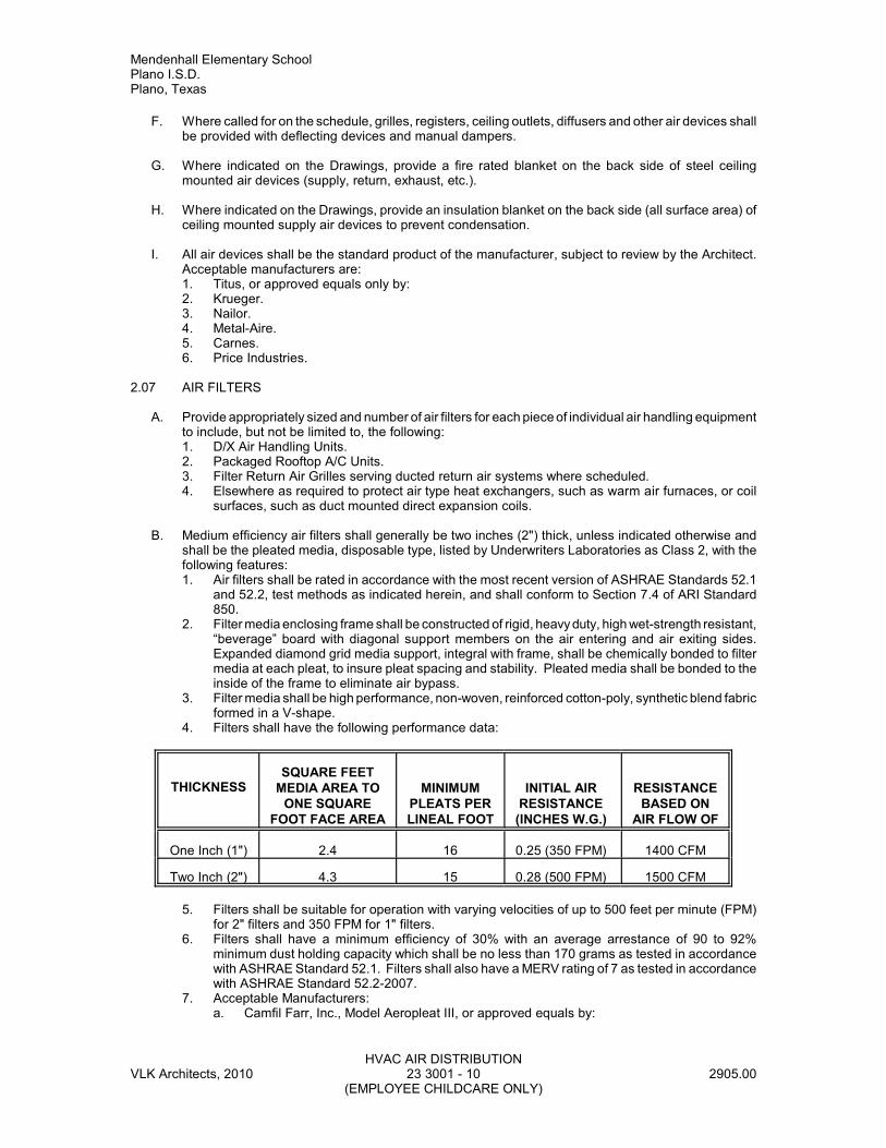
Mendenhall Elementary SchoolPlano I.S.D.Plano, Texas
HVAC AIR DISTRIBUTIONVLK Architects, 2010 23 3001 - 10 2905.00
(EMPLOYEE CHILDCARE ONLY)
F. Where called for on the schedule, grilles, registers, ceiling outlets, diffusers and other air devices shallbe provided with deflecting devices and manual dampers.
G. Where indicated on the Drawings, provide a fire rated blanket on the back side of steel ceilingmounted air devices (supply, return, exhaust, etc.).
H. Where indicated on the Drawings, provide an insulation blanket on the back side (all surface area) ofceiling mounted supply air devices to prevent condensation.
I. All air devices shall be the standard product of the manufacturer, subject to review by the Architect.Acceptable manufacturers are:1. Titus, or approved equals only by:2. Krueger.3. Nailor.4. Metal-Aire.5. Carnes.6. Price Industries.
2.07 AIR FILTERS
A. Provide appropriately sized and number of air filters for each piece of individual air handling equipmentto include, but not be limited to, the following:1. D/X Air Handling Units.2. Packaged Rooftop A/C Units.3. Filter Return Air Grilles serving ducted return air systems where scheduled.4. Elsewhere as required to protect air type heat exchangers, such as warm air furnaces, or coil
surfaces, such as duct mounted direct expansion coils.
B. Medium efficiency air filters shall generally be two inches (2") thick, unless indicated otherwise andshall be the pleated media, disposable type, listed by Underwriters Laboratories as Class 2, with thefollowing features:1. Air filters shall be rated in accordance with the most recent version of ASHRAE Standards 52.1
and 52.2, test methods as indicated herein, and shall conform to Section 7.4 of ARI Standard850.
2. Filter media enclosing frame shall be constructed of rigid, heavy duty, high wet-strength resistant,“beverage” board with diagonal support members on the air entering and air exiting sides.Expanded diamond grid media support, integral with frame, shall be chemically bonded to filtermedia at each pleat, to insure pleat spacing and stability. Pleated media shall be bonded to theinside of the frame to eliminate air bypass.
3. Filter media shall be high performance, non-woven, reinforced cotton-poly, synthetic blend fabricformed in a V-shape.
4. Filters shall have the following performance data:
THICKNESSSQUARE FEET
MEDIA AREA TOONE SQUARE
FOOT FACE AREA
MINIMUMPLEATS PERLINEAL FOOT
INITIAL AIRRESISTANCE
(INCHES W.G.)
RESISTANCEBASED ON
AIR FLOW OF
One Inch (1") 2.4 16 0.25 (350 FPM) 1400 CFM
Two Inch (2") 4.3 15 0.28 (500 FPM) 1500 CFM
5. Filters shall be suitable for operation with varying velocities of up to 500 feet per minute (FPM)for 2" filters and 350 FPM for 1" filters.
6. Filters shall have a minimum efficiency of 30% with an average arrestance of 90 to 92%minimum dust holding capacity which shall be no less than 170 grams as tested in accordancewith ASHRAE Standard 52.1. Filters shall also have a MERV rating of 7 as tested in accordancewith ASHRAE Standard 52.2-2007.
7. Acceptable Manufacturers:a. Camfil Farr, Inc., Model Aeropleat III, or approved equals by:
Mendenhall Elementary SchoolPlano I.S.D.
Plano, Texas
HVAC AIR DISTRIBUTIONVLK Architects, 2010 23 3001 - 11 2905.00
(EMPLOYEE CHILDCARE ONLY)
b. Environmental Filter Corporation.c. Eco-Air.
C. All filters shall be standard sizes that are readily and locally available, in stock, through multiple overthe counter sources without requiring special order. Standard acceptable sizes shall be 16" x 20" and16" x 25".
2.08 ADHESIVES AND SEALANTS
A. All adhesives and sealants used on this project must have a Volatile Organic Compound (VOC)content less than that listed in the current South Coast Air Quality Management District (SCAQMD)Rule 1168, and all sealants and fillers must meet or exceed the requirements of the Bay Area AirQuality Management District Regulation 8, Rule 51.
B. All adhesives and sealants shall meet the most current Leadership in Energy and EnvironmentalDesign (LEED™) requirements.
PART 3 - EXECUTION
3.01 INSTALLATION
A. Install all ductwork and equipment as indicated on the Drawings in full accordance with thesespecifications including foundations, hangers, supports, etc.
B. Seal all ductwork as specified, pressure test and repair leaks.
C. Install all air intake, relief and exhaust air hoods on continuous neoprene strips set level on top ofwood nailers of the specified roof curbs. Hoods shall be secured at 8" O.C. to the curbs with corrosionresistant screws if not secured by other fasteners as specified. Flash and counterflash to preventwater leakage through the overall roofing system.
D. Install all duct mounted components such as heating coils, electric or water type, sound attenuators,air terminals, etc. in accordance with the manufacturers recommendations.
E. Should defects or installation deficiencies become apparent, or are observed, after the systems havebeen in operation, the deficient components shall be removed and replaced or reinforced as directedby the Owner's Representative.
3.02 CLEANING OF DUCT SYSTEMS
A. Before the grilles or diffusers are installed, all fans and air conditioning units shall be operated and alldebris and foreign matter shall be removed from the ducts.
B. The air conditioning units shall be thoroughly cleaned, and the drain pans shall be thoroughly cleanedand flushed out with a hose; the filters shall be thoroughly cleaned and the grilles shall then beinstalled.
C. Insure all duct openings are capped and sealed during construction when additions are not beingmade.
3.03 AUTOMATIC CONTROL DAMPERS
A. Refer to Section 23 0900, Controls and Instrumentation.
B. Install all temperature control modulating dampers under this section of the specifications, furnishedin Section 23 0900.
Mendenhall Elementary SchoolPlano I.S.D.Plano, Texas
HVAC AIR DISTRIBUTIONVLK Architects, 2010 23 3001 - 12 2905.00
(EMPLOYEE CHILDCARE ONLY)
3.04 FILTERS
A. No air moving equipment may be operated at any time without filters being fully installed in equipment.
B. Provide a minimum of three (3) spare sets of two inch (2") thick, medium efficiency, pleated mediafilters for all air handling and fan coil units, as well as for filter return air grilles where scheduled, inaddition to manufacturer furnished filters specified elsewhere herein. Where other sections of thesespecifications require one inch (1") or four inch (4") thick filters, or other types of filters, provide sparesets of matching thickness and type.
C. Additionally Replace filters during construction as directed by the Owner's Representative.
D. Install one (1) new complete set of filters, as directed by the Test and Balance (TAB) Firm, just priorto performance of TAB work.
E. Install one (1) new set of filters at "Substantial Completion" of the project.
F. Where the minimum number of filter sets are not used for the aforementioned purposes, provide theleft over filters to the Owner for maintenance stock.
G. Document, in writing, when each filter change-out occurs.
END OF SECTION