meeting notes project 2013-03 geomagnetic … disturbance resources...meeting notes project 2013-03...
TRANSCRIPT

Meeting Notes Project 2013-03 Geomagnetic Disturbance Mitigation Standard Drafting Team Meeting March 28, 2017 | Noon - 1:15 p.m. Eastern Conference Call with Web Access Access Code: 738 370 131 Dial-in: 1-415-655-0002 (US Toll); 1-416-915-8942 (Canada Toll) Administrative
1. Introductions The meeting was brought to order by the Chair at Noon eastern on March 28, 2017. Participants were:
First Name Last Name Company Member/ Observer
Don Atkinson Georgia Transmission Corporation M
Scott Barfield-McGinnis NERC O
Emanuel Bernabeu PJM Interconnection LLC M
Regis Binder FERC O
David Boteler NRCan O
Louis Gibson Hydro-Quebec M
Frank Koza PJM Interconnection LLC M
Per-Anders Lof National Grid M
Luis Marti Hydro One M
Mary Agnes Nimis FERC O
Mark Olson NERC O
Ralph Painter Tampa Electric Co M
Lauren Perotti NERC O

Project 2013-03 GMD Mitigation Meeting Notes | March 28, 2017 2
First Name Last Name Company Member/ Observer
Antti Pulkkinen NASA M
Mike Steckelberg Great River Energy M
Rui Sun Dominion M
Berhanu Tesema BPA M
Other web participants attached
2. Determination of Quorum The rule for NERC Standard Drafting Team (SDT or team) states that a quorum requires two-thirds of the voting members of the SDT. Quorum was achieved as 11 of 13 members were present.
3. NERC Antitrust Compliance Guidelines and Public Announcement
NERC Antitrust Compliance Guidelines and public announcement were reviewed by Mark Olson. There were no questions raised.
4. Chair's remarks. Frank Koza reviewed the agenda and objectives. The purpose of the call is to describe the current drafts of TPL-007-2 and the supplemental GMD event description, and obtain feedback on the direction.
5. Discussion of working draft Supplemental GMD Event Description white paper. Luis Marti described development of Figure 1 (Supplemental Geomagnetic Field Waveshape) and Figures I-x1, I-x2, and I-x3 in the draft white paper. Synthetic enhancement was obtained by scaling linearly the horizontal x and y components of the benchmark geomagnetic field such that the peak geoelectric field will be 17 V/km. This value represents the statistically-derived 1-in-100 year peak geoelectric field of individual geomagnetic observations. Regis Binder (FERC) noted that if this value is based on the Los Alamos National Labs analysis (August 2015) then the SDT needed to consider that the data did not account for geomagnetic latitude. Antti Pulkkinen indicated that the value is based on statistical analysis, and that supporting extreme-value theory calculations are to be included in the white paper. Antti Pulkkinen and Emanuel Bernabeu will draft this section. Luis Marti reviewed the ground model (beta) scaling factors (Table II-2) and stated that they are different from the benchmark scaling factors because the frequency content of the supplemental event is different. Ralph Painter stated that justification for the supplemental assessment needs to clearly explain why, unlike benchmark assessments, corrective action plans are not required.
6. Discussion of working draft TPL-007-2. Frank Koza provided an overview of current draft. Organization is based on Emanuel Bernabeu's proposal during the previous in-person meeting. SDT agreed on the organization. Berhanu Tesema asked for clarification on the need for reporting in R7 Part 7.5. Mark Olson explained that this part was developed from previous meeting discussions

Project 2013-03 GMD Mitigation Meeting Notes | March 28, 2017 3
about situations where the CAP deadlines could not be met. The SDT agreed that wording in R10 Part 10.3 may need to be revised to address potential concerns that mitigation was implied. The SDT agreed with the direction of the draft and will review further revisions at the meeting in April.
7. Discussion of objectives and details for the April in-person meeting. The SDT agreed that the goal of the meeting is to finalize drafts for initial posting. The team will seek Standards Committee authorization to post at the June Standards Committee meeting. Mark Olson provided administrative information on the April SDT meeting.
8. Future meeting(s)
a. April 18 - 20, 2017 | NERC Headquarters, Atlanta
9. The meeting adjourned at 1:10 p.m. eastern on March 28, 2017

Supplemental Geomagnetic Disturbance Event Description Project 2013-03 GMD Mitigation Standard Drafting Team
NERC | Report Title | Report Date 1 of 24

Table of Contents Preface ........................................................................................................................................................................3 Introduction ................................................................................................................................................................4
Background .............................................................................................................................................................4
General Characteristics ...........................................................................................................................................4
Supplemental GMD Event Description .......................................................................................................................5 Supplemental GMD Event Geoelectric Field Amplitude .........................................................................................5
Reference Geomagnetic Field Waveshape .............................................................................................................5
Appendix I – Technical Considerations .......................................................................................................................7 Statistical Considerations ........................................................................................................................................7
Synthetic Enhancement ....................................................................................................................................... 13
Impact of the supplemental Waveshape on Transformer Hot-spot Heating ...................................................... 15
Appendix II – Scaling the Supplemental Benchmark GMD Event ............................................................................ 17 Scaling the Geomagnetic Field ............................................................................................................................. 17
Scaling the Geoelectric Field ................................................................................................................................ 18
Example Calculations ........................................................................................................................................... 22
Example 1 ......................................................................................................................................................... 22 Example 2 ......................................................................................................................................................... 22
References ............................................................................................................................................................... 23
NERC | Supplemental GMD Event Description| April 2017 2 of 24

Preface The North American Electric Reliability Corporation (NERC) is a not-for-profit international regulatory authority whose mission is to ensure the reliability of the Bulk-Power System (BPS) in North America. NERC develops and enforces Reliability Standards; annually assesses seasonal and long-term reliability; monitors the BPS through system awareness; and educates, trains, and certifies industry personnel. NERC’s area of responsibility spans the continental United States, Canada, and the northern portion of Baja California, Mexico. NERC is the electric reliability organization (ERO) for North America, subject to oversight by the Federal Energy Regulatory Commission (FERC) and governmental authorities in Canada. NERC’s jurisdiction includes users, owners, and operators of the BPS, which serves more than 334 million people. The North American BPS is divided into several assessment areas within the eight Regional Entity (RE) boundaries, as shown in the map and corresponding table below.
FRCC Florida Reliability Coordinating Council
MRO Midwest Reliability Organization NPCC Northeast Power Coordinating Council
RF ReliabilityFirst Corporation SERC SERC Reliability Corporation SPP RE Southwest Power Pool Regional Entity
Texas RE Texas Reliability Entity WECC Western Electric Coordinating Council
NERC | Supplemental GMD Event Description| April 2017 3 of 24

Introduction Background Proposed TPL-007-2 includes requirements for entities to perform two types of GMD Vulnerability Assessments to evaluate the potential impacts of GMD events on the Bulk Electric System (BES). The benchmark GMD Vulnerability Assessment is based on the benchmark GMD event associated with TPL-007-1 which was approved by the Federal Energy Regulatory Commission (FERC) in Order No. 830 in September 2016. The benchmark GMD event is derived from spatially-averaged geoelectric field values to address potential wide-area effects that could be caused by a severe 1-in-100 year GMD event.1 Proposed TPL-007-2 also requires entities to perform a supplemental GMD Vulnerability Assessment to evaluate risks that localized enhancements of geomagnetic field during a severe GMD event "could potentially affect the reliable operation of the Bulk-Power System".2 (The Benchmark GMD event is explained in a separate whitepaper, Benchmark GMD Event Description.) The purpose of the supplemental geomagnetic disturbance (GMD) event description is to provide a defined event for assessing system performance for a GMD event which includes a local enhancement of the geomagnetic field. In addition to varying with time, geomagnetic fields can be spatially non-uniform with higher and lower strengths across a region. This spatial non-uniformity has been observed in a number of GMD events, so localized enhancement of field strength above the average value is considered.This local enhancement is temporally and spatially limited and has been observed in a number of GMD events. The supplemental GMD event defines the geomagnetic and geoelectric field values used to compute geomagnetically-induced current (GIC) flows for a supplemental GMD Vulnerability Assessment. General Characteristics The supplemental GMD event described herein takes into consideration the characteristics of a local enhancement, recognizing that the science and understanding of these events is preliminary and evolving. Based on observations, the characteristics of local enhancements include:
• Geographic area – The extent of “local enhancements” is on the order of 100km in North-South (latitude) direction and 300-500km in East-West (longitude) direction.
• Amplitude – The amplitude of the resulting geoelectric field is on the order of twice the geoelectric field that is calculated in the spatially-averaged Benchmark GMD event.
• Pulse duration – The local enhancement occurs over the time period of 2-5 minutes. • Latitudinal locatione Extent –”Local enhancements” have only been observed thus far in the auroral
regions, generally above 60 degrees geomagnetic latitude.[MO1] • Geoelectric Field Waveshape – The geoelectric field waveshape has a strong influence on the hot spot
heating of transformer windings and structural parts since thermal time constants of the transformer and time to peak of storm maxima are both on the order of minutes. The frequency content of the magnetic field (dB/dt) is a function of the waveshape, which in turn has a direct effect on the geoelectric field since the earth response to external dB/dt is frequency-dependent. As with the benchmark GMD event, the supplemental GMD event waveshape is from the NRCan Ottawa OTT geomagnetic observatory magnetometer station during the March 13-14 1989 event. The synthetic “local enhancement” has been developed for use in GIC modelling, inserted atin the time when data suggests the existence of a the actual data appears to be experiencing a “local enhancement” with the characteristics described above.
1 See Benchmark Geomagnetic Disturbance Event Description white paper, May 12, 2016. Filed by NERC in RM 15-11 on June 28, 2016. 2 See Order No. 830 P. 47. On September 22, 2016, FERC directed NERC to develop modifications to the benchmark GMD event, included in TPL-007-1, such that assessments would not be based solely on spatially averaged data.
NERC | Supplemental GMD Event Description| April 2017 4 of 24

Supplemental GMD Event Description Severe geomagnetic disturbance events are high-impact, low-frequency (HILF) events [2]; thus, any benchmark event should consider the probability that the event will occur, as well as the impact or consequences of such an event. The supplemental GMD event is composed of the following elements: 1) a reference peak geoelectric field amplitude (V/km) derived from statistical analysis of historical magnetometer data[MO2]; 2) scaling factors to account for local geomagnetic latitude; 3) scaling factors to account for local earth conductivity; and 4) a reference geomagnetic field time series or waveshape to facilitate time-domain analysis of GMD impact on equipment. Supplemental GMD Event Geoelectric Field Amplitude The supplemental GMD event field amplitude was determined through statistical analysis[MO3] using the plane wave method [3]-[10] of geomagnetic field measurements from geomagnetic observatories in northern Europe [11] and the reference (Quebec) earth model shown in Table 1 [12], supplemented by data from Greenland and Alaska. For details of the statistical considerations, see Appendix I. The Quebec earth model is generally resistive and the geological structure is relatively well understood.
Table 1: Reference earth model (Quebec)
Thickness (km) Resistivity (Ω-m) 15 20,000 10 200
125 1,000 200 100 ∞ 3
The statistical analysis (see Appendix I) resulted in a conservative peak geoelectric field amplitude of approximately 17 V/km. For steady-state GIC and load flow analysis, the direction of the geoelectric field is assumed to be variable meaning that it can be in any direction (Eastward, Northward, or a vectorial combination thereof). The regional geoelectric field peak amplitude, Epeak, to be used in calculating GIC in the GIC system model can be obtained from the reference value of 17 V/km using the following relationship
Epeak = 17 × 𝛼𝛼 × 𝛽𝛽 (V/km) (1)
where α is the scaling factor to account for local geomagnetic latitude, and β is a scaling factor to account for the local earth conductivity structure (see Appendix II). Reference Geomagnetic Field Waveshape The reference geomagnetic field waveshape was selected after analyzing a number of recorded GMD events, including the reference storm of the NERC 2012 interim GMD report [14], measurements at the Nurmijarvi (NUR) and Memanbetsu (MMB) geomagnetic observatories for the “Halloween event” of October 29-31, 2003, and the March 13-14 1989 GMD event that caused the Hydro Quebec blackout. The geomagnetic field measurement record of the March 13-14 1989 GMD event, measured at NRCan’s Ottawa geomagnetic observatory, was selected as the reference geomagnetic field waveform because it provides generally conservative results when performing thermal analysis of power transformers (see Appendix I of the Benchmark GMD Event white paper)[MO4]. The reference geomagnetic field waveshape is used to calculate the GIC time series, GIC(t), required for transformer
NERC | Supplemental GMD Event Description| April 2017 5 of 24

thermal impact assessment. The reference wave shape includes a synthetic “local enhancement”, inserted at UT 1:18 March 14 in Figure 1 below[ML5]. The amplitude of the “local enhancement” is based on a statistical analysis of a number of GMD events, discussed in Appendix II. The geomagnetic latitude of the Ottawa geomagnetic observatory is 55°; therefore, the amplitude of the geomagnetic field measurement data were scaled up to the 60° reference geomagnetic latitude (see Figure 1) such that the resulting peak geoelectric field amplitude computed using the reference earth model was 17 V/km (see Figures 2). Sampling rate for the geomagnetic field waveshape is 10 seconds.
Figure 1: Supplemental Geomagnetic Field Waveshape
Red Bn (Northward), Blue Be (Eastward) Referenced to pre-event quiet conditions
Figure 2: Supplemental Geoelectric Field Waveshape Blue Ex (Northward), Red Ey (Eastward)
17 V/km
NERC | Supplemental GMD Event Description| April 2017 6 of 24

Appendix I – Technical Considerations The following sections describe the technical justification of the assumptions that were made in the development of the supplemental GMD event. Statistical Considerations The spatial structure of high-latitude geoelectric fields can be very complex during strong geomagnetic storm events [17]-[18]. One reflection of this spatial complexity is localized geomagnetic field enhancements (local enhancements) that result in high amplitude geoelectric fields in regions of a few hundred kilometers or less. Figure I-13 illustrates this spatial complexity of the storm-time geoelectric fields. In areas indicated by the bright red location, the geoelectric field can be a factor of 2-3 larger than at neighboring locations. Localized geomagnetic phenomena should not be confused with local earth structure/conductivity features [ML6]that result in consistently high geoelectric fields (e.g., coastal effects). Localized field enhancements can occur at any region exposed to auroral ionospheric electric current fluctuations.
Figure I-1: Illustration of the Spatial Scale between Localized Enhancements and Larger Spatial Scale Amplitudes of Geoelectric Field Observed during a Strong Geomagnetic Storm. In this illustration, the red square illustrates a spatially localized field enhancement.
3Figure I-1 is for illustration purposes only, and is not meant to suggest that a particular area is more likely to experience a localized enhanced geoelectric field.
NERC | Supplemental GMD Event Description| April 2017 7 of 24

The Supplemental GMDsupplemental GMD event is designed to address local effects caused by a severe GMD event, such as increased var VAR absorption and voltage depressions. It is important to note that most earlier geoelectric field amplitude statistics and extreme amplitude analyses have been built for individual stations thus reflecting only localized spatial scales [ML7][10], [19]-[22]. [MO8] A number of GMD events were analyzed to identify the basic characteristics of existence of “local enhancements” and to determine the basic characteristics so that some form of analysis could proceed. The following tThree (3) events studied and described below arewere studied: • March 13, 1989 • October 29-30, 2003 • March 17, 2015 Geomagnetic field recordings were collected for these storms and the geoelectric field was computed using the 1D plane wave method and the Quebec ground model. In each case, a “local enhancement” was correlated, generally oriented parallel to the westward ionospheric electrojet[ML9]. (See Figures 4-7 below)
Figure 4 – March 13, 1989, at 21.44 UT , Brorfelde (BFE), Denmark
BFE Station
Spatially correlated enhancement
NERC | Supplemental GMD Event Description| April 2017 8 of 24

Figure 5 – October 29, 2003, at 06:47 UT, Narsarsuaq (NAQ), Greenland
Figure 6 – October 30, 2003, at 16:49UT, Hopen Island (HOP), [ML10][MO11]Svalbard, Norway
Spatially correlated enhancement
NAQ Station
HOP Station Spatially correlated enhancement
NERC | Supplemental GMD Event Description| April 2017 9 of 24

Figure 7 – March 17, 2015, at 13:33 UT, Deadhorse, Alaska All of the above events were analyzed by reviewing the time series magnetic field data and transforming it to an electric field and focusing on the time period of the spatially correlated local enhancement. There were apparent similarities in the character of the local enhancements. The local enhancements occurred during peak periods of substorm activity and were distinguished by relatively brief excursions of rapid magnetic field variation. With respect to electric field amplitude, the local enhancements appeared to be on the order of 2 times the amplitude that was occurring during the substorm. With respect to time duration, the local enhancements generally occurred for 2-5 minutes. (See Figures 8-11)
Figure 8 -- March 13, 1989, at 21.44 UT , Brorfelde (BFE), Denmark
DED Station
Spatially correlated enhancement
NERC | Supplemental GMD Event Description| April 2017 10 of 24

Figure 9 -- October 29, 2003, at 06:47 UT, Narsarsuaq (NAQ), Greenland
Figure 10 -- October 30, 2003, at 16:49UT, Hopen Island (HOP), Svalbard, Norway
NERC | Supplemental GMD Event Description| April 2017 11 of 24

Figure 11 – March 17, 2015, at 13:33 UT, Deadhorse, Alaska Based on the above analysis and the previous work associated with the benchmark GMD event, it is reasonable to incorporate a second (or supplemental) assessment into TPL-007 to account for the potential impact of a local enhancement in both the network analysis and the transformer hot-spot heating analysis. Given the factor of 2 amplitude enhancement and the 2-5 minute time duration from the recent analysis, the magnitude of the supplemental GMD event is set at 17 V/km with an approximate [ML12]pulse width duration of 5 minutes to be conservative. With respect to geographic area, the historical geomagnetic field data provides limited insight. However, the westward ionospheric electrojet is a primary driver of the local enhancement phenomenon, indicating that the area of geomagnetic field enhancement will occur in a relatively narrow band of geomagnetic latitude and wider longitudinal width.The degree to which the “local enhancement” parallels the westward ionospheric electrojet suggests a relatively narrow latitude extent as compared to the longitudinal extent. Given the uncertainty, the suggested “local enhancement” footprint is suggested to be[ML13] This is represented in Figure 12 below, with geoelectric field enhancement in an area of at least 100km north-south byand 300 km east-west. Figure 12 Proposed TPL-007-2 provides flexibility for planners to determine how to apply the supplemental GMD event to the planning area.How the geographic extent is applied in the Benchmark GMD event network analysis is left to the planner because there is a wide A continent-wide method is not practical and does not account for the variety in the size and topography of the various transmission systems in North America. One example approach is for The the planner may choose to apply the Supplemental GMDenhanced geoelectric field event to the planner’s entire system (over the entire geographic area). An alternative approach is for the planner to apply a 300 km by
Benchmark geoelectric field
Enhanced geoelectric field
NERC | Supplemental GMD Event Description| April 2017 12 of 24

500 km geoelectric field enhancement over a portion of the system and apply the benchmark GMD event over the rest of the system. or portions of it. Also, the fact that “local enhancements” have only been observed thus far in the auroral regions (north of 60 degrees geomagnetic latitude) suggests that the network analysis be conducted with the application of the adjustment factors per the Benchmark GMD event to inform the planner of potential impacts. (See Appendix II) However, tThehe development of a corrective action plan per TPL-007 is not required. [ML14] Synthetic Enhancement The location of the synthetic enhancement was identified as a portion of the benchmark geomagnetic field that shared a number of the characteristics of observed local enhancements described above. This also corresponds to part of the benchmark event with the highest geoelectric field. The synthetic enhancement was constructed by scaling linearly a 4.6 minute portion of the benchmark geomagnetic field so that the peak geoelectric field is 17 V/km at a geomagnetic latitude of 60° and the benchmark reference earth model. Figure I-x1 shows the benchmark geomagnetic field and Figure I-x2 shows the supplemental benchmark geomagnetic field. Figure I-x3 shows a time expansion zooms intoof Bx, with and without the synthetic enhancement.
Figure I-x1: Benchmark geomagnetic field. Bx (red), By (blue)
Potential enhancement
NERC | Supplemental GMD Event Description| April 2017 13 of 24

Figure I-x2: Supplemental Benchmark geomagnetic field. Bx (red), By (blue)
Figure I-x3: Benchmark Bx (red) and supplemental Bx field (blue) – expanded view
Synthetic enhancement
Benchmark
Enhancement
4.6 minutes
NERC | Supplemental GMD Event Description| April 2017 14 of 24

Impact of the supplemental Waveshape on Transformer Hot-spot Heating Thermal effects (e.g. hot spot transformer heating) in power transformers are not instantaneous. Thermal time constants associated with hot spot heating in power transformers are in the 5-20 minute range; therefore, the waveshape of the geomagnetic and geoelectric field has a strong impact on transformer hot spot heating of windings and metallic parts since thermal time constants are of the same order of magnitude as the time-to-peak of storm maxima. From a hot spot heating point of view, the local enhancement of the supplemental benchmark waveshape has a material impact on the temperature rise even though the duration of the local enhancement is approximately 5 minutes. Figure I-x4 shows the results of thousands of thermal assessments for all combinations of effective GIC due to circuit orientation. The horizontal axis represents peak effective GIC(t) current and the vertical axis represents peak metallic hot spot temperature. The combined envelope of these two curves is similar to the screening criterion of the benchmark event.
Figure I-x4: Calculated Peak Metallic for all possible circuit orientations and peak effective GIC(t).[ML15]
NERC | Supplemental GMD Event Description| April 2017 15 of 24

NERC | Supplemental GMD Event Description| April 2017 16 of 24
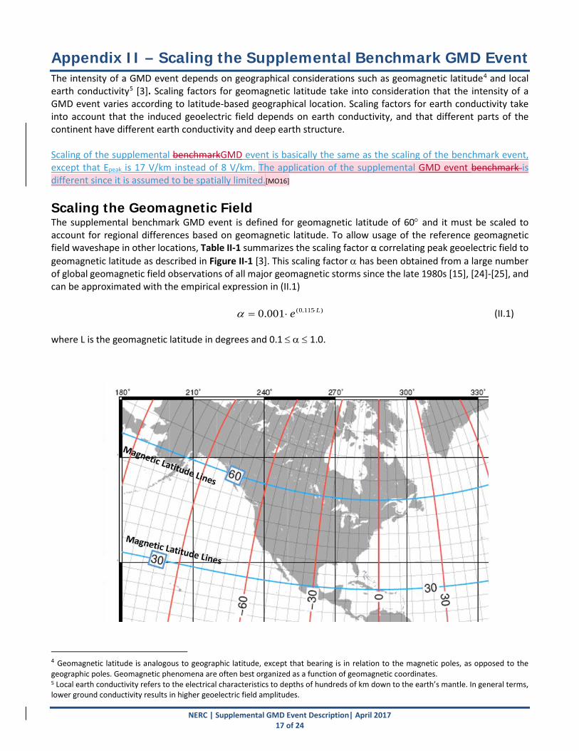
Appendix II – Scaling the Supplemental Benchmark GMD Event The intensity of a GMD event depends on geographical considerations such as geomagnetic latitude4 and local earth conductivity5 [3]. Scaling factors for geomagnetic latitude take into consideration that the intensity of a GMD event varies according to latitude-based geographical location. Scaling factors for earth conductivity take into account that the induced geoelectric field depends on earth conductivity, and that different parts of the continent have different earth conductivity and deep earth structure. Scaling of the supplemental benchmarkGMD event is basically the same as the scaling of the benchmark event, except that Epeak is 17 V/km instead of 8 V/km. The application of the supplemental GMD event benchmark is different since it is assumed to be spatially limited.[MO16] Scaling the Geomagnetic Field The supplemental benchmark GMD event is defined for geomagnetic latitude of 60° and it must be scaled to account for regional differences based on geomagnetic latitude. To allow usage of the reference geomagnetic field waveshape in other locations, Table II-1 summarizes the scaling factor α correlating peak geoelectric field to geomagnetic latitude as described in Figure II-1 [3]. This scaling factor α has been obtained from a large number of global geomagnetic field observations of all major geomagnetic storms since the late 1980s [15], [24]-[25], and can be approximated with the empirical expression in (II.1)
)115.0(001.0 Le ⋅⋅=α (II.1) where L is the geomagnetic latitude in degrees and 0.1 ≤ α ≤ 1.0.
4 Geomagnetic latitude is analogous to geographic latitude, except that bearing is in relation to the magnetic poles, as opposed to the geographic poles. Geomagnetic phenomena are often best organized as a function of geomagnetic coordinates. 5 Local earth conductivity refers to the electrical characteristics to depths of hundreds of km down to the earth’s mantle. In general terms, lower ground conductivity results in higher geoelectric field amplitudes.
NERC | Supplemental GMD Event Description| April 2017 17 of 24

Figure II-1: Geomagnetic Latitude Lines in North America
Table II-1: Geomagnetic Field Scaling Factors Geomagnetic Latitude
(Degrees) Scaling Factor1
(α) ≤ 40 0.10 45 0.2 50 0.3 54 0.5 56 0.6 57 0.7 58 0.8 59 0.9
≥ 60 1.0 Scaling the Geoelectric Field The benchmark GMD event is defined for the reference Quebec earth model provided in Table 1. This earth model has been used in many peer-reviewed technical articles [12, 15]. The peak geoelectric field depends on the geomagnetic field waveshape and the local earth conductivity. Ideally, the peak geoelectric field, Epeak, is obtained by calculating the geoelectric field from the scaled geomagnetic waveshape using the plane wave method and taking the maximum value of the resulting waveforms
(II.2)
where, * denotes convolution in the time domain, z(t) is the impulse response for the earth surface impedance calculated from the laterally uniform or 1D earth
model, BE(t), BN(t) are the scaled Eastward and Northward geomagnetic field waveshapes, EE(t), EN(t)| are the magnitudes of the calculated Eastward and Northward geoelectric field EE(t) and EN(t). As noted previously, the response of the earth to B(t) (and dB/dt) is frequency dependent. Figure II-2 shows the magnitude of Z(ω) for the reference earth model.
)(),(max)(*)/)((
)(*)/)((
tEtEEtBtzE
tBtzE
NEpeak
NoE
EoN
=
−==
µµ
NERC | Supplemental GMD Event Description| April 2017 18 of 24

Figure II-2: Magnitude of the Earth Surface Impedance for the Reference Earth
Model If a utility does not have the capability of calculating the waveshape or time series for the geoelectric field, an earth conductivity scaling factor β can be obtained from Table II-2. Using α and β, the peak geoelectric field Epeak for a specific service territory shown in Figure II-3 can be obtained using (II.3)
Epeak = 17 × 𝛼𝛼 × 𝛽𝛽 (V/km) (II.3) It should be noted that (II.3) is an approximation based on the following assumptions:
• The earth models used to calculate Table II-2 for the United States are from published information available on the USGS website6.
• The models used to calculate Table II-2 for Canada were obtained from NRCan and reflect the average structure for large regions. When models are developed for sub-regions, there will be variance (to a greater or lesser degree) from the average model. For instance, detailed models for Ontario have been developed by NRCan and consist of seven major sub-regions.
• The conductivity scaling factor β is calculated as the quotient of the local geoelectric field peak amplitude in a physiographic region with respect to the reference peak amplitude value of 17 V/km. Both geoelectric field peaks amplitudes are calculated using the supplemental [ML17]geomagnetic field time series. If a different geomagnetic field time series were used, the calculated scaling factors β would be different than the values in Table II-2 because the frequency content of storm maxima is, in principle, different for every storm. If a utility has technically-sound earth models for its service territory and sub-regions thereof, then the use of such earth models is preferable to estimate Epeak.
• When a ground conductivity model is not available the planning entity should use the largest β factor of adjacent physiographic regions or a technically-justified value.
66 address
NERC | Supplemental GMD Event Description| April 2017 19 of 24

Physiographic Regions of the Continental United States
Physiographic Regions of Canada
Figure II-3: Physiographic Regions of North America[ML18][MO19]
Table II-2 Geoelectric Field Scaling Factors
CP-3
FL-1
NERC | Supplemental GMD Event Description| April 2017 20 of 24

USGS Earth model
Scaling Factor (β)
AK1A 0.4856 AK1B 0.4856 AP1 0.3328 AP2 0.0.7682 BR1 0.2222 CL1 0.7176 CO1 0.2527 CP1 0.8081 CP2 0.9195 FL1 0.74 CS1 0.3541 IP1 0.8994 IP2 0.2428 IP3 0.8893 IP4 0.3341 NE1 0.7481 PB1 0.5162 PB2 0.3646 PT1 1.1917 SL1 0.4653 SU1 0.8893 BOU 0.2228 FBK 0.5756 PRU 0.2221 BC 0.6067
PRAIRIES 0.8496 SHIELD 1.0
ATLANTIC 0.7479
NERC | Supplemental GMD Event Description| April 2017 21 of 24

Example Calculations[ML20] Example 1 Consider a transmission service territory that lies in a geographical latitude of 45.5°, which translates to a geomagnetic latitude of 55°. The scaling factor α calculated using II.1 is 0.56; therefore, the benchmark waveshape and the peak geoelectric field will be scaled accordingly. If the service territory has the same earth conductivity as the benchmark then β=1, and the peak geoelectric field will be
kmVEpeak /5.9156.0170.156.0
=××===
βα
If the service territory spans more than one physiographic region (i.e. several locations within the service territory have a different earth model) then the largest α can be used across the entire service territory for conservative results. Alternatively, the network can be split into multiple subnetworks, and the corresponding geoelectric field amplitude can be applied to each subnetwork. Example 2 Consider a service territory that lies in a geographical latitude of 45.5° which translates to a geomagnetic latitude of 55°. The scaling factor α calculated using II.1 is 0.56; therefore, the benchmark waveshape and the peak geoelectric field will be scaled accordingly. The service territory has lower conductivity than the reference benchmark conductivity, therefore, according to the conductivity factor β from Table II-2., the calculation follows:
Conductivity factor β=1.17
kmEpeak /1.1117.156.01756.0
=××==α
NERC | Supplemental GMD Event Description| April 2017 22 of 24

References
[1] L. Bolduc, A. Gaudreau, A. Dutil, “Saturation Time of Transformers Under dc Excitation”, Electric Power Systems Research, 56 (2000), pp. 95-102
[2] High-Impact, Low-Frequency Event Risk to the North American Bulk Power System, A Jointly-
Commissioned Summary Report of the North American Reliability Corporation and the U.S. Department of Energy’s November 2009 Workshop.
[3] Application Guide: Computing Geomagnetically-Induced Current in the Bulk-Power System, NERC.
NERC. http://www.nerc.com/comm/PC/Geomagnetic%20Disturbance%20Task%20Force%20GMDTF%202013/GIC%20Application%20Guide%202013_approved.pdf
[4] Kuan Zheng, Risto Pirjola, David Boteler, Lian-guang Liu, “Geoelectric Fields Due to Small-Scale and
Large-Scale Source Currents”, IEEE Transactions on Power Delivery, Vol. 28, No. 1, January 2013, pp. 442-449.
[5] Boteler, D. H. “Geomagnetically Induced Currents: Present Knowledge and Future Research”, IEEE
Transactions on Power Delivery, Vol. 9, No. 1, January 1994, pp. 50-58. [6] Boteler, D. H. “Modeling Geomagnetically Induced Currents Produced by Realistic and Uniform Electric
Fields”, IEEE Transactions on Power Delivery, Vol. 13, No. 4, January 1998, pp. 1303-1308. [7] J. L. Gilbert, W. A. Radasky, E. B. Savage, “A Technique for Calculating the Currents Induced by
Geomagnetic Storms on Large High Voltage Power Grids”, Electromagnetic Compatibility (EMC), 2012 IEEE International Symposium on.
[8] How to Calculate Electric Fields to Determine Geomagnetically-Induced Currents. EPRI, Palo Alto, CA:
2013. 3002002149. [9] Pulkkinen, A., R. Pirjola, and A. Viljanen, Statistics of extreme geomagnetically induced current events,
Space Weather, 6, S07001, doi:10.1029/2008SW000388, 2008. [10] Boteler, D. H., Assessment of geomagnetic hazard to power systems in Canada, Nat. Hazards, 23, 101–
120, 2001.
[11] Finnish Meteorological Institute’s IMAGE magnetometer chain data available at: http://image.gsfc.nasa.gov/
[12] Boteler, D. H., and R. J. Pirjola, The complex-image method for calculating the magnetic and electric
fields produced at the surface of the Earth by the auroral electrojet, Geophys. J. Int., 132(1), 31—40, 1998
[13] ANSI Standard C2, National Electric Safety Code, 2012, ISBN 978-0-7381-6588-2 [14] 2012 Special Reliability Assessment Interim Report: Effects of Geomagnetic Disturbances on the Bulk
Power System. NERC. February 2012. http://www.nerc.com/pa/RAPA/ra/Reliability%20Assessments%20DL/2012GMD.pdf
NERC | Supplemental GMD Event Description| April 2017 23 of 24

[15] Pulkkinen, A., E. Bernabeu, J. Eichner, C. Beggan and A. Thomson, Generation of 100-year
geomagnetically induced current scenarios, Space Weather, Vol. 10, S04003, doi:10.1029/2011SW000750, 2012.
[16] Love, J., Credible occurrence probabilities for extreme geophysical events: Earthquakes, volcanic
eruptions, magnetic storms, Geophysical Research Letters, Vol. 39, L10301, doi:10.1029/2012GL051431, 2012.
[17] Pulkkinen, A., A. Thomson, E. Clarke, and A. Mckay, April 2000 geomagnetic storm: ionospheric drivers
of large geomagnetically induced currents, Annales Geophysicae, 21, 709-717, 2003. [18] Pulkkinen, A., S. Lindahl, A. Viljanen, and R. Pirjola, Geomagnetic storm of 29–31 October 2003:
Geomagnetically induced currents and their relation to problems in the Swedish high-voltage power transmission system, Space Weather, 3, S08C03, doi:10.1029/2004SW000123, 2005.
[19] Pulkkinen, A., R. Pirjola, and A. Viljanen, Statistics of extreme geomagnetically induced current events,
Space Weather, 6, S07001, doi:10.1029/2008SW000388, 2008. [20] Langlois, P., L. Bolduc, and M. C. Chouteau, Probability of occurrence of geomagnetic storms based on a
study of the distribution of the electric field amplitudes measured in Abitibi, Que bec, in 1993–1994, J. Geomagn. Geoelectr., 48, 1033–1041, 1996.
[21] Pulkkinen, A., R. Pirjola, and A. Viljanen, Statistics of extreme geomagnetically induced current events, Space Weather, 6, S07001, doi:10.1029/2008SW000388, 2008.
[22] Campbell, W. C., Observation of electric currents in the Alaska oil pipeline resulting from auroral
electrojet current sources, Geophys. J. R. Astron. Soc., 61, 437–449, 1980. [23] Coles, Stuart (2001). An Introduction to Statistical Modelling of Extreme Values. Springer.
[24] Ngwira, C., A. Pulkkinen, F. Wilder, and G. Crowley, Extended study of extreme geoelectric field event
scenarios for geomagnetically induced current applications, Space Weather, Vol. 11, 121–131, doi:10.1002/swe.20021, 2013.
[25] Thomson, A., S. Reay, and E. Dawson. Quantifying extreme behavior in geomagnetic activity, Space
Weather, 9, S10001, doi:10.1029/2011SW000696, 2011.
DB: Add reference to: Nikitina, L., Trichtchenko, L., Boteler, D.H., Assessment of extreme values in geomagnetic and geoelectric field
variation for Canada, Space Weather J., 14, doi:10.1002/2016SW001386, 2016.[ML21]
NERC | Supplemental GMD Event Description| April 2017 24 of 24

TPL-007-1 2 — Transmission System Planned Performance for Geomagnetic Disturbance Events
A. Introduction
1. Title: Transmission System Planned Performance for Geomagnetic Disturbance Events
2. Number: TPL-007-12
3. Purpose: Establish requirements for Transmission system planned performance during geomagnetic disturbance (GMD) events.
4. Applicability:
4.1. Functional Entities:
4.1.1 Planning Coordinator with a planning area that includes a Facility or Facilities specified in 4.2;
4.1.2 Transmission Planner with a planning area that includes a Facility or Facilities specified in 4.2;
4.1.3 Transmission Owner who owns a Facility or Facilities specified in 4.2; 4.1.4 Generator Owner who owns a Facility or Facilities specified in 4.2.
4.2. Facilities:
4.2.1 Facilities that include power transformer(s) with a high side, wye-grounded winding with terminal voltage greater than 200 kV.
5. Background:
During a GMD event, geomagnetically-induced currents (GIC) may cause transformer hot-spot heating or damage, loss of Reactive Power sources, increased Reactive Power demand, and Misoperation(s), the combination of which may result in voltage collapse and blackout.
6. Effective Date:
See Implementation Plan for TPL-007-1
B. Requirements and Measures
R1. Each Planning Coordinator, in conjunction with its Transmission Planner(s), shall identify the individual and joint responsibilities of the Planning Coordinator and Transmission Planner(s) in the Planning Coordinator’s planning area for maintaining models and performing the study or studies needed to complete GMD Vulnerability Assessment(s). [Violation Risk Factor: Lower] [Time Horizon: Long-term Planning]
M1. Each Planning Coordinator, in conjunction with its Transmission Planners, shall provide documentation on roles and responsibilities, such as meeting minutes, agreements, copies of procedures or protocols in effect between entities or between departments of a vertically integrated system, or email correspondence that identifies an agreement has been reached on individual and joint responsibilities for maintaining models and
Page 1 of 37

TPL-007-1 2 — Transmission System Planned Performance for Geomagnetic Disturbance Events
performing the study or studies needed to complete GMD Vulnerability Assessment(s), in accordance with Requirement R1.
R2. Each responsible entity, as determined in Requirement R1, shall maintain System models and GIC System models of the responsible entity’s planning area for performing the study or studies needed to complete GMD Vulnerability Assessment(s). [Violation Risk Factor: High] [Time Horizon: Long-term Planning]
M2. Each responsible entity, as determined in Requirement R1, shall have evidence in either electronic or hard copy format that it is maintaining System models and GIC System models of the responsible entity’s planning area for performing the study or studies needed to complete GMD Vulnerability Assessment(s).
R3. Each responsible entity, as determined in Requirement R1, shall have criteria for acceptable System steady state voltage performance for its System during the benchmark GMD event described in Attachment 1. [Violation Risk Factor: Medium] [Time Horizon: Long-term Planning]
M3. Each responsible entity, as determined in Requirement R1, shall have evidence, such as electronic or hard copies of the criteria for acceptable System steady state voltage performance for its System in accordance with Requirement R3.
Benchmark GMD Vulnerability Assessment(s)
R4. Each responsible entity, as determined in Requirement R1, shall complete a benchmark GMD Vulnerability Assessment of the Near-Term Transmission Planning Horizon once every 60 calendar months. This benchmark GMD Vulnerability Assessment shall use a study or studies based on models identified in Requirement R2, document assumptions, and document summarized results of the steady state analysis. [Violation Risk Factor: High] [Time Horizon: Long-term Planning]
4.1. The study or studies shall include the following conditions:
4.1.1. System On-Peak Load for at least one year within the Near-Term Transmission Planning Horizon; and
4.1.2. System Off-Peak Load for at least one year within the Near-Term Transmission Planning Horizon.
4.2. The study or studies shall be conducted based on the benchmark [PAL1]GMD event described in Attachment 1 to determine whether the System meets the performance requirements for the steady-state planning benchmark GMD event contained in Table 1.
4.3. The benchmark GMD Vulnerability Assessment shall be provided within 90 calendar days of completion to the responsible entity’s Reliability Coordinator, adjacent Planning Coordinators, adjacent Transmission Planners, and to any functional entity that submits a written request and has a reliability-related need.
Page 2 of 37

TPL-007-1 2 — Transmission System Planned Performance for Geomagnetic Disturbance Events
4.3.1. If a recipient of the benchmark GMD Vulnerability Assessment provides documented comments on the results, the responsible entity shall provide a documented response to that recipient within 90 calendar days of receipt of those comments.
M4. Each responsible entity, as determined in Requirement R1, shall have dated evidence such as electronic or hard copies of its GMD Vulnerability Assessment meeting all of the requirements in Requirement R4. Each responsible entity, as determined in Requirement R1, shall also provide evidence, such as email records, web postings with an electronic notice of posting, or postal receipts showing recipient and date, that it has distributed its GMD Vulnerability Assessment within 90 calendar days of completion to its Reliability Coordinator, adjacent Planning Coordinator(s), adjacent Transmission Planner(s), and to any functional entity who has submitted a written request and has a reliability-related need as specified in Requirement R4. Each responsible entity, as determined in Requirement R1, shall also provide evidence, such as email notices or postal receipts showing recipient and date, that it has provided a documented response to comments received on its GMD Vulnerability Assessment within 90 calendar days of receipt of those comments in accordance with Requirement R4.
R5. Each [PAL2]responsible entity, as determined in Requirement R1, shall provide GIC flow information to be used for the transformer thermal impact assessment specified in Requirement R6 to each Transmission Owner and Generator Owner that owns an applicable Bulk Electric System (BES) power transformer in the planning area. The GIC flow information shall include: [Violation Risk Factor: Medium] [Time Horizon: Long-term Planning]
5.1. The maximum effective GIC value for the worst case geoelectric field orientation for the benchmark GMD event described in Attachment 1. This value shall be provided to the Transmission Owner or Generator Owner that owns each applicable BES power transformer in the planning area.
5.2. The effective GIC time series, GIC(t), calculated using the benchmark GMD event described in Attachment 1 in response to a written request from the Transmission Owner or Generator Owner that owns an applicable BES power transformer in the planning area. GIC(t) shall be provided within 90 calendar days of receipt of the written request and after determination of the maximum effective GIC value in Part 5.1.
M5. Each responsible entity, as determined in Requirement R1, shall provide evidence, such as email records, web postings with an electronic notice of posting, or postal receipts showing recipient and date, that it has provided the maximum effective GIC value to the Transmission Owner and Generator Owner that owns each applicable BES power transformer in the planning area as specified in Requirement R5, Part 5.1. Each responsible entity, as determined in Requirement R1, shall also provide evidence, such as email records, web postings with an electronic notice of posting, or postal receipts showing recipient and date, that it has provided GIC(t) in response to a written request
Page 3 of 37

TPL-007-1 2 — Transmission System Planned Performance for Geomagnetic Disturbance Events
from the Transmission Owner or Generator Owner that owns an applicable BES power transformer in the planning area.
R6. Each Transmission Owner and Generator Owner shall conduct a benchmark thermal impact assessment for its solely and jointly owned applicable BES power transformers where the maximum effective GIC value provided in Requirement R5, Part 5.1, is 75 A per phase or greater. The benchmark thermal impact assessment shall: [Violation Risk Factor: Medium] [Time Horizon: Long-term Planning]
6.1. Be based on the effective GIC flow information provided in Requirement R5; 6.2. Document assumptions used in the analysis; 6.3. Describe suggested actions and supporting analysis to mitigate the impact of
GICs, if any; and 6.4. Be performed and provided to the responsible entities, as determined in
Requirement R1, within 24 calendar months of receiving GIC flow information specified in Requirement R5, Part 5.1.
M6. Each Transmission Owner and Generator Owner shall have evidence such as electronic or hard copies of its benchmark thermal impact assessment for all of its solely and jointly owned applicable BES power transformers where the maximum effective GIC value provided in Requirement R5, Part 5.1, is 75 A per phase or greater, and shall have evidence such as email records, web postings with an electronic notice of posting, or postal receipts showing recipient and date, that it has provided its thermal impact assessment to the responsible entities as specified in Requirement R6.
R7. Each responsible entity, as determined in Requirement R1, that concludes, through the benchmark GMD Vulnerability Assessment conducted in Requirement R4, that their System does not meet the performance requirements of Table 1 shall develop a Corrective Action Plan addressing how the performance requirements will be met. The Corrective Action Plan shall: [Violation Risk Factor: High] [Time Horizon: Long-term Planning]
7.1. List System deficiencies and the associated actions needed to achieve required System performance. Examples of such actions include:
• Installation, modification, retirement, or removal of Transmission and generation Facilities and any associated equipment.
• Installation, modification, or removal of Protection Systems or Special Protection Systems.
• Use of Operating Procedures, specifying how long they will be needed as part of the Corrective Action Plan.
• Use of Demand-Side Management, new technologies, or other initiatives.
7.2. Be developed within one year of completion of the GMD Vulnerability Assessment.[PAL3]
Page 4 of 37

TPL-007-1 2 — Transmission System Planned Performance for Geomagnetic Disturbance Events
7.3. Include a timetable for implementing the selected actions from Part 7.1. The timetable shall:
7.3.1. Specify implementation of non-hardware mitigation, if any, within two years of development of the Corrective Action Plan;
7.3.2. Specify implementation of hardware mitigation, if any, within four years of development of the Corrective Action Plan;
Be developed within one year of completion of the GMD Vulnerability Assessment.[PAL4]
Be revised, when necessary, to document actions taken by the Responsible Entity to address circumstances outside the Responsible Entity's control that prevent the implementation of actions according to the timetable in Part 7.2.[MO5] [PAL6]
7.4. Be reviewed in subsequent GMD Vulnerability Assessments until it is determined that the System meets the performance requirements contained in Table 1.
7.5. Be revised and reported to the Regional Entity Iif situations beyond the control of the responsible entity, as determined in Requirement R1, prevent implementation of the Corrective Action Plan within the timetable for implementation provided in Part 7.3, the responsible entity shall report the prohibiting circumstances, and provide an updated Corrective Action Plan and timetable for implementing the selected actions from Part 7.1 [PAL7]to the Regional Reliability Organization [cc:ERO?][PAL8]. The report shall provided documentation [PAL9]shall include the following:
7.5.1. Prohibiting circumstances causing the delay for fully or partially implementing the selected actions in Part 7.1; [reason/rationale][PAL10]
7.5.2. Description of the original and any previous changes to the Corrective Action Plan with the associated timetable(s) for implementing the selected actions in Part 7.1; [present CAP] and
7.5.3. Description of changes to the previous Corrective Action Plan(s), including utilization of Operating Procedures, and the [PAL11]updated timetable for implementing the selected actions in Part 7.1; and. [new CAP]
7.3.7.5.4. Updates to Part 7.5.1 through 7.5.3, provided at least once every 12 months until the actions of Part 7.3 are implemented.If updated Corrective Action Plan(s) including timetable(s) for implementation has been filed with the Regional Reliability Organization [cc: ERO?][PAL12], the responsible entity, as determined in Requirement R1, shall update the filing(s) provided in Part 7.5 on an annual basis until it is determined that the System meets the performance requirements for the steady-state
Page 5 of 37

TPL-007-1 2 — Transmission System Planned Performance for Geomagnetic Disturbance Events
planning benchmark GMD event contained in Table 1. [periodic review requirement][PAL13][MO14]
7.4.7.6. Be provided within 90 calendar days of completion development or revision to the responsible entity’s Reliability Coordinator, adjacent Planning Coordinator(s), adjacent Transmission Planner(s), functional entities referenced in the Corrective Action Plan, and any functional entity that submits a written request and has a reliability-related need.
7.4.1.7.6.1. If a recipient of the Corrective Action Plan provides documented comments on the results, the responsible entity shall provide a documented response to that recipient within 90 calendar days of receipt of those comments.
M7. Each responsible entity, as determined in Requirement R1, that concludes, through the benchmark GMD Vulnerability Assessment conducted in Requirement R4, that the responsible entity’s System does not meet the performance requirements for the steady-state planning benchmark GMD event of Table 1 shall have evidence such as electronic or hard copies of its Corrective Action Plan, as specified in Requirement R7. Each responsible entity, as determined in Requirement R1, shall also provide evidence, such as email records, web postings with an electronic notice of posting, or postal receipts showing recipient and date, that it has distributed its Corrective Action Plan or relevant information, if any, within 90 calendar days of its completion to its Reliability Coordinator, adjacent Planning Coordinator(s), adjacent Transmission Planner(s), a functional entity referenced in the Corrective Action Plan, and any functional entity that submits a written request and has a reliability-related need, as specified in Requirement R7. Each responsible entity, as determined in Requirement R1, shall also provide evidence, such as email notices or postal receipts showing recipient and date, that it has provided a documented response to comments received on its Corrective Action Plan within 90 calendar days of receipt of those comments, in accordance with Requirement R7.[PAL15]
Supplemental GMD Vulnerability Assessment(s)
R8. Supplemental GMD Vulnerability Assessment. [PAL16]In addition to the bBenchmark GMD Vulnerability Assessment described in R4, each responsible entity, as determined in Requirement R1, shall complete a sSupplemental[PAL17] GMD Vulnerability Assessment of the Near-Term Transmission Planning Horizon once every 60 calendar months. This sSupplemental GMD Vulnerability Assessment shall use a study or studies based on models identified in Requirement R2, document assumptions, and document summarized results of the steady state analysis. [Violation Risk Factor: High] [Time Horizon: Long-term Planning]
8.1. The study or studies shall include the following conditions:
Page 6 of 37

TPL-007-1 2 — Transmission System Planned Performance for Geomagnetic Disturbance Events
8.1.1. System On-Peak Load for at least one year within the Near-Term Transmission Planning Horizon; and
8.1.2. System Off-Peak Load for at least one year within the Near-Term Transmission Planning Horizon.
System On-Peak Load for at least one year within the Near-Term Transmission Planning Horizon; and
System Off-Peak Load for at least one year within the Near-Term Transmission Planning Horizon.[PAL18]
8.2 Study or studies shall be conducted based on the sSupplemental GMD event described in Attachment 1 to determine whether the System meets the performance requirements for the sSupplemental GMD event in Table 1.
8.3 If the analysis concludes there is Cascading caused by the sSupplemental GMD event described in Attachment 1, an evaluation of possible actions designed to reduce the likelihood or mitigate the consequences and adverse impacts of the event(s) shall be conducted.
8.4 The GMD Vulnerability Assessment shall be provided within 90 calendar days of completion to the responsible entity’s Reliability Coordinator, adjacent Planning Coordinators, adjacent Transmission Planners, and to any functional entity that submits a written request and has a reliability-related need.
8.5 4.4.1. If a recipient of the GMD Vulnerability Assessment provides documented comments on the results, the responsible entity shall provide a documented response to that recipient within 90 calendar days of receipt of those comments.
M8. Each responsible entity, as determined in Requirement R1, shall have dated evidence such as electronic or hard copies of its GMD Vulnerability Assessment meeting all of the requirements in Requirement R4. Each responsible entity, as determined in Requirement R1, shall also provide evidence, such as email records, web postings with an electronic notice of posting, or postal receipts showing recipient and date, that it has distributed its GMD Vulnerability Assessment within 90 calendar days of completion to its Reliability Coordinator, adjacent Planning Coordinator(s), adjacent Transmission Planner(s), and to any functional entity who has submitted a written request and has a reliability-related need as specified in Requirement R4. Each responsible entity, as determined in Requirement R1, shall also provide evidence, such as email notices or postal receipts showing recipient and date, that it has provided a documented response to comments received on its GMD Vulnerability Assessment within 90 calendar days of receipt of those comments in accordance with Requirement R4.
R9. Each [PAL19]responsible entity, as determined in Requirement R1, shall provide GIC flow information to be used for the supplemental transformer thermal impact assessment specified in Requirement R10 to each Transmission Owner and Generator Owner that owns an applicable Bulk Electric System (BES) power transformer in the planning area. The GIC flow information shall include: [Violation Risk Factor: Medium] [Time Horizon: Long-term Planning]
Page 7 of 37

TPL-007-1 2 — Transmission System Planned Performance for Geomagnetic Disturbance Events
9.1. The maximum effective GIC value for the worst case geoelectric field orientation for the supplemental GMD event described in Attachment 1. This value shall be provided to the Transmission Owner or Generator Owner that owns each applicable BES power transformer in the planning area.
9.2. The effective GIC time series, GIC(t), calculated using the supplemental GMD event described in Attachment 1 in response to a written request from the Transmission Owner or Generator Owner that owns an applicable BES power transformer in the planning area. GIC(t) shall be provided within 90 calendar days of receipt of the written request and after determination of the maximum effective GIC value in Part 5.1.
M9. Each responsible entity, as determined in Requirement R1, shall provide evidence, such as email records, web postings with an electronic notice of posting, or postal receipts showing recipient and date, that it has provided the maximum effective benchmark GIC value to the Transmission Owner and Generator Owner that owns each applicable BES power transformer in the planning area as specified in Requirement R5, Part 5.1. Each responsible entity, as determined in Requirement R1, shall also provide evidence, such as email records, web postings with an electronic notice of posting, or postal receipts showing recipient and date, that it has provided GIC(t) in response to a written request from the Transmission Owner or Generator Owner that owns an applicable BES power transformer in the planning area.
R10. Supplemental Transformer Thermal Impact Assessment. [PAL20] Each Transmission Owner and Generator Owner shall conduct a thermal impact assessment for its solely and jointly owned applicable BES power transformers where the maximum effective GIC value provided in Requirement R5, Part 5.1, is xxx A per phase or greater. The thermal impact assessment shall: [Violation Risk Factor: Medium] [Time Horizon: Long-term Planning]
10.1. Be based on the effective GIC flow information provided in Requirement R89;
10.2. Document assumptions used in the analysis;
10.3. Describe suggested actions and supporting analysis to mitigate the impact of GICs, if any; and
10.4. Be performed and provided to the responsible entities, as determined in Requirement R1, within 24 calendar months of receiving GIC flow information specified in Requirement R9, Part 9.1[PAL21]
R9[PAL22]. Supplemental Transformer Thermal Impact Assessment. Each Transmission Owner and Generator Owner shall conduct a thermal impact assessment for its solely and jointly owned applicable BES power transformers where the maximum effective GIC value provided in Requirement R5, Part 5.1, is xxx A per phase or greater. The thermal impact assessment shall: [Violation Risk Factor: Medium] [Time Horizon: Long-term Planning]
9.1. Be based on the effective GIC flow information provided in Requirement R8;
Page 8 of 37

TPL-007-1 2 — Transmission System Planned Performance for Geomagnetic Disturbance Events
9.2. Document assumptions used in the analysis;
9.3. Describe suggested actions and supporting analysis to mitigate the impact of GICs, if any; and
9.4. Be performed and provided to the responsible entities, as determined in Requirement R1, within 24 calendar months of receiving GIC flow information specified in Requirement R5, Part 5.1.M10[PAL23] Each Transmission Owner and Generator Owner [PAL24]shall have evidence such as electronic or hard copies of its supplemental thermal impact assessment for all of its solely and jointly owned applicable BES power transformers where the maximum effective GIC value provided in Requirement R9, Part 9.1, is XX A per phase or greater, and shall have evidence such as email records, web postings with an electronic notice of posting, or postal receipts showing recipient and date, that it has provided its thermal impact assessment to the responsible entities as specified in Requirement R10.
GMD Data Processes
R11. GIC Monitor Data Collection. Each responsible entity, as determined in Requirement R1, shall implement a process to obtain GIC monitor data from at least one (1) GIC monitor located in the Planning Coordinator's planning area or other part of the system included in the Planning Coordinator's GIC System model.
M11. Each responsible entity, as determined in Requirement R1, shall provide evidence, such as email records, web postings with an electronic notice of posting, or postal receipts showing recipient and date, that it has … [PAL25]
R12. Magnetometer Data Collection. Each responsible entity, as determined in Requirement R1, shall implement a process to obtain geomagnetic field data from at least one (1) magnetometer located in the Planning Coordinator's planning area or other part of the system included in the Planning Coordinator's GIC System model
M12. Each responsible entity, as determined in Requirement R1, shall provide evidence, such as email records, web postings with an electronic notice of posting, or postal receipts showing recipient and date, that it has …[PAL26]
R10. GIC Monitor Data Collection. Each responsible entity, as determined in Requirement R1, shall implement a process to obtain GIC monitor data from at least one (1) GIC monitor located in the Planning Coordinator's planning area or other part of the system included in the Planning Coordinator's GIC System model.
R11. Magnetometer Data Collection. Each responsible entity, as determined in Requirement R1, shall implement a process to obtain geomagnetic field data from at least one (1) magnetometer located in the Planning Coordinator's planning area or other part of the system included in the Planning Coordinator's GIC System model. [PAL27]
Page 9 of 37

TPL-007-1 2 — Transmission System Planned Performance for Geomagnetic Disturbance Events
Rationale for Requirements R110 and R121: The proposed requirements addresses Order No. 830 directives for requiring responsible entities to collect GIC monitoring and magnetometer data as necessary to enable model validation and situational awareness (P. 88; P. 90-92). See the Guidelines and Technical Basis Section of this standard for technical information.
Technical considerations for GIC monitoring are contained in the NERC 2012 GMD Report (see Chapter 6). GIC monitoring is generally performed by Hall-effect transducers that are attached to the neutral of the transformer and measure dc current flowing through the neutral.
Magnetometers measure changes in the earth's magnetic field. Entities should obtain data from the nearest accessible magnetometer. Sources of magnetometer data include:
• Observatories such as those operated by U.S. Geological Survey and Natural Resources Canada, see below for locations (http://www.intermagnet.org/):
• Research institutions and academic universities; • Entities with installed magnetometers. Entities that choose to install magnetometers are requested to use the equipment specifications and data format protocols contained in the latest version of the Intermagnet Technical Reference Manual (http://www.intermagnet.org/publications/intermag_4-6.pdf)
Page 10 of 37

TPL-007-1 2 — Transmission System Planned Performance for Geomagnetic Disturbance Events
Table 1 –Steady State Planning Benchmark GMD Events
Steady State: a. Voltage collapse, Cascading and uncontrolled islanding shall not occur. b. Generation loss is acceptable as a consequence of the planning bBenchmark GMD event. c. Planned System adjustments such as Transmission configuration changes and re-dispatch of generation are allowed if such adjustments
are executable within the time duration applicable to the Facility Ratings.
Category Initial Condition Event Interruption of
Firm Transmission Service Allowed
Load Loss Allowed
GMD GMD Event with Outages
1. System as may be postured in response to space weather information1, and then 2. GMD event2
Reactive Power compensation devices and other Transmission Facilities removed as a result of Protection System operation or Misoperation due to harmonics during the GMD event
Yes3 Yes3
Table 1 – Steady State Performance Footnotes
1. The System condition for GMD planning may include adjustments to posture the System that are executable in response to space weather information.
2. The GMD conditions for the planning event are described in Attachment 1 (under bBenchmark GMD eEvent). 3. Load loss as a result of manual or automatic Load shedding (e.g. UVLS) and/or curtailment of Firm Transmission Service may be used to
meet BES performance requirements during studied GMD conditions. The likelihood and magnitude of Load loss or curtailment of Firm Transmission Service should be minimized.
Page 11 of 37

TPL-007-1 2 — Transmission System Planned Performance for Geomagnetic Disturbance Events
Table 2 –Supplemental GMD Event
Steady State: a. Voltage collapse, Cascading and uncontrolled islanding shall not occur. b. Generation loss is acceptable as a consequence of the sSupplemental GMD event. c. Planned System adjustments such as Transmission configuration changes and re-dispatch of generation are allowed if such
adjustments are executable within the time duration applicable to the Facility Ratings.
Category Initial Condition Event Interruption of
Firm Transmission Service Allowed
Load Loss Allowed
GMD GMD Event with Outages
1. System as may be postured in response to space weather information1, and then 2. GMD event2
Reactive Power compensation devices and other Transmission Facilities removed as a result of Protection System operation or Misoperation due to harmonics during the GMD event
Yes Yes
Table 1 – Steady State Performance Footnotes
1. The System condition for GMD planning may include adjustments to posture the System that are executable in response to space weather information.
2. The GMD conditions for the planning event are described in Attachment 1 (under supplementalBenchmark GMD eEvent).
Page 12 of 37
TPL-007-1 2 — Transmission System Planned Performance for Geomagnetic Disturbance Events
Attachment 1
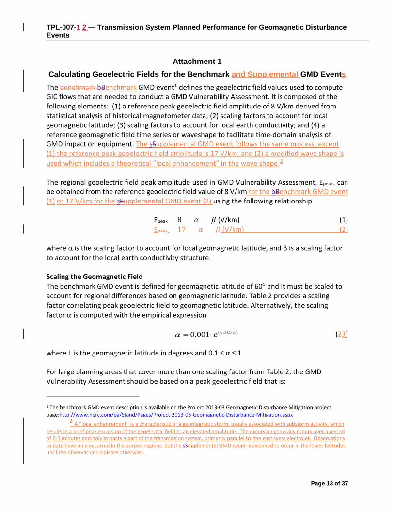
Calculating Geoelectric Fields for the Benchmark and Supplemental GMD Events The benchmark bBenchmark GMD event1 defines the geoelectric field values used to compute GIC flows that are needed to conduct a GMD Vulnerability Assessment. It is composed of the following elements: (1) a reference peak geoelectric field amplitude of 8 V/km derived from statistical analysis of historical magnetometer data; (2) scaling factors to account for local geomagnetic latitude; (3) scaling factors to account for local earth conductivity; and (4) a reference geomagnetic field time series or waveshape to facilitate time-domain analysis of GMD impact on equipment. The sSupplemental GMD event follows the same process, except (1) the reference peak geoelectric field amplitude is 17 V/km; and (2) a modified wave shape is used which includes a theoretical “local enhancement” in the wave shape.2 The regional geoelectric field peak amplitude used in GMD Vulnerability Assessment, Epeak, can be obtained from the reference geoelectric field value of 8 V/km for the bBenchmark GMD event (1) or 17 V/km for the sSupplemental GMD event (2) using the following relationship
Epeak = 8 × 𝛼𝛼 × 𝛽𝛽 (V/km) (1) Epeak = 17 × 𝛼𝛼 × 𝛽𝛽 (V/km) (2)
where α is the scaling factor to account for local geomagnetic latitude, and β is a scaling factor to account for the local earth conductivity structure. Scaling the Geomagnetic Field The benchmark GMD event is defined for geomagnetic latitude of 60° and it must be scaled to account for regional differences based on geomagnetic latitude. Table 2 provides a scaling factor correlating peak geoelectric field to geomagnetic latitude. Alternatively, the scaling factor α is computed with the empirical expression
)115.0(001.0 Le ⋅⋅=α (23) where L is the geomagnetic latitude in degrees and 0.1 ≤ α ≤ 1 For large planning areas that cover more than one scaling factor from Table 2, the GMD Vulnerability Assessment should be based on a peak geoelectric field that is:
1 The benchmark GMD event description is available on the Project 2013-03 Geomagnetic Disturbance Mitigation project page:http://www.nerc.com/pa/Stand/Pages/Project-2013-03-Geomagnetic-Disturbance-Mitigation.aspx
2 A “local enhancement” is a characteristic of a geomagnetic storm, usually associated with substorm activity, which results in a brief peak excursion of the geoelectric field to an elevated amplitude. The excursion generally occurs over a period of 2-5 minutes and only impacts a part of the transmission system, primarily parallel to the east-west electrojet. Observations to date have only occurred in the auroral regions, but the sSupplemental GMD event is assumed to occur in the lower latitudes until the observations indicate otherwise.
Page 13 of 37

TPL-007-1 2 — Transmission System Planned Performance for Geomagnetic Disturbance Events
• calculated by using the most conservative (largest) value for α; or • calculated assuming a non-uniform or piecewise uniform geomagnetic field.
Page 14 of 37

TPL-007-1 2 — Transmission System Planned Performance for Geomagnetic Disturbance Events
Table 2− Geomagnetic Field Scaling Factors Geomagnetic Latitude
(Degrees) Scaling Factor1
(α) ≤ 40 0.10 45 0.2 50 0.3 54 0.5 56 0.6 57 0.7 58 0.8 59 0.9
≥ 60 1.0
Scaling the Geoelectric Field The benchmark GMD event is defined for the reference Quebec earth model described in Table 4. The peak geoelectric field, Epeak, used in a GMD Vulnerability Assessment may be obtained by either
• Calculating the geoelectric field for the ground conductivity in the planning area and the reference geomagnetic field time series scaled according to geomagnetic latitude, using a procedure such as the plane wave method described in the NERC GMD Task Force GIC Application Guide;3 or
• Using the earth conductivity scaling factor β from Table 3 that correlates to the ground conductivity map in Figure 1 or Figure 2. Along with the scaling factor α from equation (23) or Table 2, β is applied to the reference geoelectric field using equation (1 or 2, as applicable) to obtain the regional geoelectric field peak amplitude Epeak to be used in GMD Vulnerability Assessments. When a ground conductivity model is not available, the planning entity should use the largest β factor of adjacent physiographic regions or a technically justified value.
The earth models used to calculate Table 3 for the United States were obtained from publicly available information published on the U. S. Geological Survey website.4 The models used to calculate Table 3 for Canada were obtained from Natural Resources Canada (NRCan) and reflect the average structure for large regions. A planner can also use specific earth model(s) with documented justification and the reference geomagnetic field time series to calculate the β factor(s) as follows:
𝛽𝛽 = 𝐸𝐸/8 for the bBenchmark GMD event (34) β = E/17 for the sSupplemental GMD event (5)
3 Available at the NERC GMD Task Force project page: http://www.nerc.com/comm/PC/Pages/Geomagnetic-Disturbance-Task-Force-(GMDTF)-2013.aspx
4 Available at http://geomag.usgs.gov/conductivity/
Page 15 of 37

TPL-007-1 2 — Transmission System Planned Performance for Geomagnetic Disturbance Events
where E is the absolute value of peak geoelectric in V/km obtained from the technically justified earth model and the reference geomagnetic field time series. For large planning areas that span more than one β scaling factor, the most conservative (largest) value for β may be used in determining the peak geoelectric field to obtain conservative results. Alternatively, a planner could perform analysis using a non-uniform or piecewise uniform geoelectric field.
Page 16 of 37

TPL-007-1 2 — Transmission System Planned Performance for Geomagnetic Disturbance Events
Figure 1: Physiographic Regions of the Continental United States5
Figure 2: Physiographic Regions of Canada
5 Additional map detail is available at the U.S. Geological Survey (http://geomag.usgs.gov/)
FL-1
Page 17 of 37

TPL-007-1 2 — Transmission System Planned Performance for Geomagnetic Disturbance Events
Table 3 − Geoelectric Field Scaling Factors USGS
Earth model Scaling Factor
(β) AK1A 0.56 AK1B 0.56 AP1 0.33 AP2 0.82 BR1 0.22 CL1 0.76 CO1 0.27 CP1 0.81 CP2 0.95 FL1 0.74 CS1 0.41 IP1 0.94 IP2 0.28 IP3 0.93 IP4 0.41 NE1 0.81 PB1 0.62 PB2 0.46 PT1 1.17 SL1 0.53 SU1 0.93 BOU 0.28 FBK 0.56 PRU 0.21 BC 0.67
PRAIRIES 0.96 SHIELD 1.0
ATLANTIC 0.79
Table 4 − Reference Earth Model (Quebec)
Layer Thickness (km) Resistivity (Ω-m)
15 20,000
10 200
125 1,000
200 100
∞ 3
Page 18 of 37

TPL-007-1 2 — Transmission System Planned Performance for Geomagnetic Disturbance Events
Reference Geomagnetic Field Time Series or Waveshape for the Benchmark GMD Event6 The geomagnetic field measurement record of the March 13-14 1989 GMD event, measured at NRCan’s Ottawa geomagnetic observatory is the basis for the reference geomagnetic field waveshape to be used to calculate the GIC time series, GIC(t), required for transformer thermal impact assessment.
The geomagnetic latitude of the Ottawa geomagnetic observatory is 55°; therefore, the amplitude of the geomagnetic field measurement data were scaled up to the 60° reference geomagnetic latitude (see Figure 3) such that the resulting peak geoelectric field amplitude computed using the reference earth model was 8 V/km (see Figures 4 and 5). Sampling rate for the geomagnetic field waveshape is 10 seconds.7 To use this geoelectric field time series when a different earth model is applicable, it should be scaled with the appropriate conductivity scaling factor β.
Figure 3: Benchmark Geomagnetic Field Waveshape. Red Bn (Northward), Blue Be (Eastward)
6 Refer to the Benchmark GMD Event Description for details on the determination of the reference geomagnetic field waveshape: http://www.nerc.com/pa/Stand/Pages/Project-2013-03-Geomagnetic-Disturbance-Mitigation.aspx
7 The data file of the benchmark geomagnetic field waveshape is available on the NERC GMD Task Force project page: http://www.nerc.com/comm/PC/Pages/Geomagnetic-Disturbance-Task-Force-(GMDTF)-2013.aspx
Page 19 of 37

TPL-007-1 2 — Transmission System Planned Performance for Geomagnetic Disturbance Events
Figure 4: Benchmark Geoelectric Field Waveshape - EE (Eastward)
Figure 5: Benchmark Geoelectric Field Waveshape – EN (Northward)
Page 20 of 37

TPL-007-1 2 — Transmission System Planned Performance for Geomagnetic Disturbance Events
Reference Geomagnetic Field Time Series or Waveshape for the Supplemental GMD Event8 The geomagnetic field measurement record of the March 13-14 1989 GMD event, measured at NRCan’s Ottawa geomagnetic observatory is the basis for the reference geomagnetic field waveshape to be used to calculate the GIC time series, GIC(t), required for transformer thermal impact assessment for the sSupplemental GMD eEvent. However, due to the incorporation of a “local enhancement” into the wave shape for the sSupplemental GMD event, the wave shape is different from the bBenchmark GMD eEvent wave shape.
To account for the fact that the sSupplemental GMD eEvent is intended to represent a local impact, the waveshape is to be applied to a local area to be justified by the responsible entity. Given that the size of the area expected to be impacted by a “local enhancement” is still somewhat unknown, the responsible entity has flexibility to apply the sSupplemental GMD eEvent waveshape in a limited area of the system and to a limited number of transformers at the discretion of the responsible entity. Assumptions in this regard will need to be documented.
The geomagnetic latitude of the Ottawa geomagnetic observatory is 55°; therefore, the amplitude of the geomagnetic field measurement data were scaled up to the 60° reference geomagnetic latitude (see Figure ?) such that the resulting peak geoelectric field amplitude computed using the reference earth model was 17 V/km (see Figures x and y). Sampling rate for the geomagnetic field waveshape is 10 seconds.9 To use this geoelectric field time series when a different earth model is applicable, it should be scaled with the appropriate conductivity scaling factor β. New Wave shapes inserted here
8 9 The data file of the benchmark geomagnetic field waveshape is available on the NERC GMD Task Force project page: http://www.nerc.com/comm/PC/Pages/Geomagnetic-Disturbance-Task-Force-(GMDTF)-2013.aspx
Page 21 of 37

TPL-007-1 2 — Transmission System Planned Performance for Geomagnetic Disturbance Events
C. Compliance
1. Compliance Monitoring Process 1.1. Compliance Enforcement Authority
As defined in the NERC Rules of Procedure, “Compliance Enforcement Authority” means NERC or the Regional Entity in their respective roles of monitoring and enforcing compliance with the NERC Reliability Standards
1.2. Evidence Retention The following evidence retention periods identify the period of time an entity is required to retain specific evidence to demonstrate compliance. For instances where the evidence retention period specified below is shorter than the time since the last audit, the CEA may ask an entity to provide other evidence to show that it was compliant for the full time period since the last audit. The Planning Coordinator, Transmission Planner, Transmission Owner, and Generator Owner shall keep data or evidence to show compliance as identified below unless directed by its Compliance Enforcement Authority to retain specific evidence for a longer period of time as part of an investigation:
For Requirements R1, R2, R3, R5, and R6, each responsible entity shall retain documentation as evidence for five years.
For Requirement R4, each responsible entity shall retain documentation of the current GMD Vulnerability Assessment and the preceding GMD Vulnerability Assessment.
For Requirement R7, each responsible entity shall retain documentation as evidence for five years or until all actions in the Corrective Action Plan are completed, whichever is later.
If a Planning Coordinator, Transmission Planner, Transmission Owner, or Generator Owner is found non-compliant it shall keep information related to the non-compliance until mitigation is complete and approved or for the time specified above, whichever is longer.
The Compliance Enforcement Authority shall keep the last audit records and all requested and submitted subsequent audit records.
1.3. Compliance Monitoring and Assessment Processes: Compliance Audits Self-Certifications Spot Checking Compliance Investigations Self-Reporting Complaints
1.4. Additional Compliance Information
Page 22 of 37

TPL-007-1 2 — Transmission System Planned Performance for Geomagnetic Disturbance Events
None
Page 23 of 37

TPL-007-1 2 — Transmission System Planned Performance for Geomagnetic Disturbance Events
Table of Compliance Elements
R # Time Horizon
VRF Violation Severity Levels
Lower VSL Moderate VSL High VSL Severe VSL
R1 Long-term Planning
Lower N/A N/A N/A The Planning Coordinator, in conjunction with its Transmission Planner(s), failed to determine and identify individual or joint responsibilities of the Planning Coordinator and Transmission Planner(s) in the Planning Coordinator’s planning area for maintaining models and performing the study or studies needed to complete GMD Vulnerability Assessment(s).
R2 Long-term Planning
High N/A N/A The responsible entity did not maintain either System models or GIC System models of the responsible
The responsible entity did not maintain both System models and GIC System models of the responsible
Page 24 of 37

TPL-007-1 2 — Transmission System Planned Performance for Geomagnetic Disturbance Events
entity’s planning area for performing the study or studies needed to complete GMD Vulnerability Assessment(s).
entity’s planning area for performing the study or studies needed to complete GMD Vulnerability Assessment(s).
R3 Long-term Planning
Medium N/A N/A N/A The responsible entity did not have criteria for acceptable System steady state voltage performance for its System during the benchmark GMD event described in Attachment 1 as required.
R4 Long-term Planning
High The responsible entity completed a GMD Vulnerability Assessment, but it was more than 60 calendar months and less than or equal to 64 calendar months since the last GMD Vulnerability Assessment.
The responsible entity's completed GMD Vulnerability Assessment failed to satisfy one of elements listed in Requirement R4, Parts 4.1 through 4.3;
OR
The responsible entity completed a GMD Vulnerability Assessment, but it
The responsible entity's completed GMD Vulnerability Assessment failed to satisfy two of the elements listed in Requirement R4, Parts 4.1 through 4.3; OR The responsible entity completed a GMD Vulnerability Assessment, but it
The responsible entity's completed GMD Vulnerability Assessment failed to satisfy three of the elements listed in Requirement R4, Parts 4.1 through 4.3; OR
The responsible entity completed a GMD Vulnerability Assessment, but it
Page 25 of 37

TPL-007-1 2 — Transmission System Planned Performance for Geomagnetic Disturbance Events
was more than 64 calendar months and less than or equal to 68 calendar months since the last GMD Vulnerability Assessment.
was more than 68 calendar months and less than or equal to 72 calendar months since the last GMD Vulnerability Assessment.
was more than 72 calendar months since the last GMD Vulnerability Assessment;
OR
The responsible entity does not have a completed GMD Vulnerability Assessment.
R5 Long-term Planning
Medium The responsible entity provided the effective GIC time series, GIC(t), in response to written request, but did so more than 90 calendar days and less than or equal to 100 calendar days after receipt of a written request.
The responsible entity provided the effective GIC time series, GIC(t), in response to written request, but did so more than 100 calendar days and less than or equal to 110 calendar days after receipt of a written request.
The responsible entity provided the effective GIC time series, GIC(t), in response to written request, but did so more than 110 calendar days after receipt of a written request.
The responsible entity did not provide the maximum effective GIC value to the Transmission Owner and Generator Owner that owns each applicable BES power transformer in the planning area; OR The responsible entity did not provide the effective GIC time series, GIC(t), upon written request.
Page 26 of 37

TPL-007-1 2 — Transmission System Planned Performance for Geomagnetic Disturbance Events
R6 Long-term Planning
Medium The responsible entity failed to conduct a thermal impact assessment for 5% or less or one of its solely owned and jointly owned applicable BES power transformers (whichever is greater) where the maximum effective GIC value provided in Requirement R5, Part 5.1, is 75 A or greater per phase; OR The responsible entity conducted a thermal impact assessment for its solely owned and jointly owned applicable BES power transformers where the maximum effective GIC value provided in Requirement R5, Part 5.1, is 75 A or greater per phase but did so more than 24 calendar months and less than
The responsible entity failed to conduct a thermal impact assessment for more than 5% up to (and including) 10% or two of its solely owned and jointly owned applicable BES power transformers (whichever is greater) where the maximum effective GIC value provided in Requirement R5, Part 5.1, is 75 A or greater per phase; OR The responsible entity conducted a thermal impact assessment for its solely owned and jointly owned applicable BES power transformers where the maximum effective GIC value provided in Requirement R5, Part 5.1, is 75 A or greater per phase but did so
The responsible entity failed to conduct a thermal impact assessment for more than 10% up to (and including) 15% or three of its solely owned and jointly owned applicable BES power transformers (whichever is greater) where the maximum effective GIC value provided in Requirement R5, Part 5.1, is 75 A or greater per phase; OR The responsible entity conducted a thermal impact assessment for its solely owned and jointly owned applicable BES power transformers where the maximum effective GIC value provided in Requirement R5, Part 5.1, is 75 A or greater per phase but did so
The responsible entity failed to conduct a thermal impact assessment for more than 15% or more than three of its solely owned and jointly owned applicable BES power transformers (whichever is greater) where the maximum effective GIC value provided in Requirement R5, Part 5.1, is 75 A or greater per phase; OR The responsible entity conducted a thermal impact assessment for its solely owned and jointly owned applicable BES power transformers where the maximum effective GIC value provided in Requirement R5, Part 5.1, is 75 A or greater per phase but did so more than 30 calendar
Page 27 of 37

TPL-007-1 2 — Transmission System Planned Performance for Geomagnetic Disturbance Events
or equal to 26 calendar months of receiving GIC flow information specified in Requirement R5, Part 5.1.
more than 26 calendar months and less than or equal to 28 calendar months of receiving GIC flow information specified in Requirement R5, Part 5.1; OR The responsible entity failed to include one of the required elements as listed in Requirement R6, Parts 6.1 through 6.3.
more than 28 calendar months and less than or equal to 30 calendar months of receiving GIC flow information specified in Requirement R5, Part 5.1; OR The responsible entity failed to include two of the required elements as listed in Requirement R6, Parts 6.1 through 6.3.
months of receiving GIC flow information specified in Requirement R5, Part 5.1; OR The responsible entity failed to include three of the required elements as listed in Requirement R6, Parts 6.1 through 6.3.
R7 Long-term Planning
High N/A The responsible entity's Corrective Action Plan failed to comply with one of the elements in Requirement R7, Parts 7.1 through 7.3.
The responsible entity's Corrective Action Plan failed to comply with two of the elements in Requirement R7, Parts 7.1 through 7.3.
The responsible entity's Corrective Action Plan failed to comply with all three of the elements in Requirement R7, Parts 7.1 through 7.3; OR The responsible entity did not have a Corrective Action Plan as required by Requirement R7.
Page 28 of 37

TPL-007-1 2 — Transmission System Planned Performance for Geomagnetic Disturbance Events
D. Regional Variances None.
E. Interpretations None.
F. Associated Documents None.
Version History
Version Date Action Change Tracking
1 December 17, 2014 Adopted by the NERC Board of Trustees
Page 29 of 37

Application Guidelines
Guidelines and Technical Basis Benchmark GMD Event (Attachment 1)[PAL28] The benchmark GMD event defines the geoelectric field values used to compute GIC flows that are needed to conduct a benchmark GMD Vulnerability Assessment. A white paper that includes the event description, analysis, and example calculations is available on the Project 2013-03 Geomagnetic Disturbance Mitigation project page at: http://www.nerc.com/pa/Stand/Pages/Project-2013-03-Geomagnetic-Disturbance-Mitigation.aspx[PAL29]
Supplemental GMD Event (Attachment 1) The supplemental GMD event defines the geoelectric field values used to compute GIC flows that are needed to conduct a supplemental GMD Vulnerability Assessment. A white paper that includes the event description, analysis, and example calculations is available on the Project 2013-03 Geomagnetic Disturbance Mitigation project page:[PAL30] Requirement R2 A GMD Vulnerability Assessment requires a GIC System model, which is a dc representation of the System, to calculate GIC flow. In a GMD Vulnerability Assessment, GIC simulations are used to determine transformer Reactive Power absorption and transformer thermal response. Details for developing the GIC System model are provided in the NERC GMD Task Force guide: Application Guide for Computing Geomagnetically-Induced Current in the Bulk Power System. The guide is available at: http://www.nerc.com/comm/PC/Geomagnetic%20Disturbance%20Task%20Force%20GMDTF%202013/GIC%20Application%20Guide%202013_approved.pdf
Underground pipe-type cables present a special modeling situation in that the steel pipe that encloses the power conductors significantly reduces the geoelectric field induced into the conductors themselves, while they remain a path for GIC. Solid dielectric cables that are not enclosed by a steel pipe will not experience a reduction in the induced geoelectric field. A planning entity should account for special modeling situations in the GIC system model, if applicable.
Requirement R4 The GMD Planning Guide developed by the NERC GMD Task Force provides technical information on GMD-specific considerations for planning studies. It is available at: http://www.nerc.com/comm/PC/Geomagnetic%20Disturbance%20Task%20Force%20GMDTF%202013/GMD%20Planning%20Guide_approved.pdf
The diagram below provides an overall view of the GMD Vulnerability Assessment process:
Page 30 of 37

Application Guidelines
Requirement R5 The transformer thermal impact assessment specified in Requirement R6 is based on GIC information for the Benchmark GMD Event. This GIC information is determined by the planning entity through simulation of the GIC System model and must be provided to the entity responsible for conducting the thermal impact assessment. GIC information should be provided in accordance with Requirement R5 each time the GMD Vulnerability Assessment is performed since, by definition, the GMD Vulnerability Assessment includes a documented evaluation of susceptibility to localized equipment damage due to GMD. The maximum effective GIC value provided in Part 5.1 is used for transformer thermal impact assessment. Only those transformers that experience an effective GIC value of 75 A or greater per phase require evaluation in Requirement R6.
GIC(t) provided in Part 5.2 is used to convert the steady-state GIC flows to time-series GIC data for transformer thermal impact assessment. This information may be needed by one or more of the methods for performing a thermal impact assessment. Additional information is in the following section and the thermal impact assessment white paper.
The peak GIC value of 75 Amps per phase has been shown through thermal modeling to be a conservative threshold below which the risk of exceeding known temperature limits established by technical organizations is low.
Requirement R6
Page 31 of 37

Application Guidelines
The thermal impact assessment of a power transformer may be based on manufacturer-provided GIC capability curves, thermal response simulation, thermal impact screening, or other technically justified means. Approaches for conducting the assessment are presented in the Transformer Thermal Impact Assessment white paper posted on the project page. http://www.nerc.com/pa/Stand/Pages/Project-2013-03-Geomagnetic-Disturbance-Mitigation.aspx
Transformers are exempt from the thermal impact assessment requirement if the effective GIC value for the transformer is less than 75 A per phase, as determined by a GIC analysis of the System. Justification for this criterion is provided in the Screening Criterion for Transformer Thermal Impact Assessment white paper posted on the project page. A documented design specification exceeding this value is also a justifiable threshold criterion that exempts a transformer from Requirement R6.
The threshold criteria and transformer thermal impact must be evaluated on the basis of effective GIC. Refer to the white papers for additional information.
Requirement R7 Technical considerations for GMD mitigation planning, including operating and equipment strategies, are available in Chapter 5 of the GMD Planning Guide. Additional information is available in the 2012 Special Reliability Assessment Interim Report: Effects of Geomagnetic Disturbances on the Bulk-Power System: http://www.nerc.com/pa/RAPA/ra/Reliability%20Assessments%20DL/2012GMD.pdf
Requirement R10
Technical considerations for GIC monitoring are contained in the NERC 2012 GMD Report (see Chapter 6). GIC monitoring is generally performed by Hall-effect transducers that are attached to the neutral of the wye-grounded transformer. Data from GIC monitors is useful model validation and situational awareness.
Responsible entities consider the following in developing a process for obtaining GIC monitor data:
• Monitor locations. An entity's operating process may be constrained by location of existing GIC monitors. However, when planning for additional GIC monitoring installations consider that data from monitors located in areas found to have high GIC based on system studies may provide more useful information for validation and situational awareness purposes. Conversely, data from GIC monitors that are located in the vicinity of transportation systems using direct current (e.g. subways or light rail) may be unreliable.
• Monitor specifications. Capabilities of Hall-effect transducers, existing and planned, should be considered in the operating process. When planning new GIC monitor installations, consider monitor data range (for example, -500A through + 500A) and ambient temperature ratings consistent with temperatures in the region in which the monitor will be installed.
Page 32 of 37

Application Guidelines
• Sampling Interval. An entity's operating process may be constrained by capabilities of existing GIC monitors. However, when possible specify data sampling during periods of interest at a rate of 10s or faster.
• Collection Periods. The process should specify when the entity expects GIC data to be collected. For example, collection could be required during periods where the Kp index is above a threshold, or when GIC values are above a threshold. Determining when to discontinue collecting GIC data should also be specified to maintain consistency in data collection.
• Data format. Specify time and value formats. For example, Greenwich Mean Time (GMT) (MM/DD/YYYY HH:MM:SS) and GIC Value (Amps). Positive (+) and negative (-) signs indicate direction of GIC flow (Positive reference is flow from ground into transformer neutral). Time fields should indicate the sampled time rather than system or SCADA time if GIC monitor system capability supports.
• Data retention. The entity's process should specify data retention periods, for example 1 year. Data retention periods should be adequately long to support availability for the entity's model validation process and external reporting requirements, if any.
• Additional information. The entity's process should specify collection of other information necessary for making the data useful, for example monitor location and type of neutral connection (e.g. three-phase or single-phase).
Requirement R11
Magnetometers measure changes in the earth's magnetic field. Entities should obtain data from the nearest accessible magnetometer. Sources of magnetometer data include:
• Observatories such as those operated by U.S. Geological Survey and Natural Resources Canada, see below for locations (http://www.intermagnet.org/):
• Research institutions and academic universities;
Page 33 of 37

Application Guidelines
• Entities with installed magnetometers.
Entities that choose to install magnetometers should consider equipment specifications and data format protocols contained in the latest version of the Intermagnet Technical Reference Manual (http://www.intermagnet.org/publications/intermag_4-6.pdf)
Page 34 of 37

Application Guidelines
Rationale:
During development of this standard, text boxes were embedded within the standard to explain the rationale for various parts of the standard. Upon BOT approval, the text from the rationale text boxes was moved to this section.
Rationale for Applicability: Instrumentation transformers and station service transformers do not have significant impact on geomagnetically-induced current (GIC) flows; therefore, these transformers are not included in the applicability for this standard.
Terminal voltage describes line-to-line voltage.
Rationale for R1: In some areas, planning entities may determine that the most effective approach to conduct a GMD Vulnerability Assessment is through a regional planning organization. No requirement in the standard is intended to prohibit a collaborative approach where roles and responsibilities are determined by a planning organization made up of one or more Planning Coordinator(s).
Rationale for R2: A GMD Vulnerability Assessment requires a GIC System model to calculate GIC flow which is used to determine transformer Reactive Power absorption and transformer thermal response. Guidance for developing the GIC System model is provided in the GIC Application Guide developed by the NERC GMD Task Force and available at: http://www.nerc.com/comm/PC/Geomagnetic%20Disturbance%20Task%20Force%20GMDTF%202013/GIC%20Application%20Guide%202013_approved.pdf
The System model specified in Requirement R2 is used in conducting steady state power flow analysis that accounts for the Reactive Power absorption of power transformer(s) due to GIC in the System.
The GIC System model includes all power transformer(s) with a high side, wye-grounded winding with terminal voltage greater than 200 kV. The model is used to calculate GIC flow in the network.
The projected System condition for GMD planning may include adjustments to the System that are executable in response to space weather information. These adjustments could include, for example, recalling or postponing maintenance outages.
The Violation Risk Factor (VRF) for Requirement R2 is changed from Medium to High. This change is for consistency with the VRF for approved standard TPL-001-4 Requirement R1, which is proposed for revision in the NERC filing dated August 29, 2014 (RM12-1-000). NERC guidelines require consistency among Reliability Standards.
Rationale for R3: Requirement R3 allows a responsible entity the flexibility to determine the System steady state voltage criteria for System steady state performance for the steady-state planning benchmark
Page 35 of 37

Application Guidelines
GMD event contained in Table 1. Steady state voltage limits are an example of System steady state performance criteria.
Rationale for R4: The GMD Vulnerability Assessment includes steady state power flow analysis and the supporting study or studies using the models specified in Requirement R2 that account for the effects of GIC. Performance criteria for the steady-state planning benchmark GMD event are specified in Table 1.
At least one System On-Peak Load and at least one System Off-Peak Load must be examined in the analysis.
Distribution of GMD Vulnerability Assessment results provides a means for sharing relevant information with other entities responsible for planning reliability. Results of GIC studies may affect neighboring systems and should be taken into account by planners.
The GMD Planning Guide developed by the NERC GMD Task Force provides technical information on GMD-specific considerations for planning studies. It is available at:
http://www.nerc.com/comm/PC/Geomagnetic%20Disturbance%20Task%20Force%20GMDTF%202013/GMD%20Planning%20Guide_approved.pdf
The provision of information in Requirement R4, Part 4.3, shall be subject to the legal and regulatory obligations for the disclosure of confidential and/or sensitive information.
Rationale for R5: This GIC information is necessary for determining the thermal impact of GIC on transformers in the planning area and must be provided to entities responsible for performing the thermal impact assessment so that they can accurately perform the assessment. GIC information should be provided in accordance with Requirement R5 as part of the GMD Vulnerability Assessment process since, by definition, the GMD Vulnerability Assessment includes documented evaluation of susceptibility to localized equipment damage due to GMD.
The maximum effective GIC value provided in Part 5.1 is used for transformer thermal impact assessment.
GIC(t) provided in Part 5.2 can alternatively be used to convert the steady-state GIC flows to time-series GIC data for transformer thermal impact assessment. This information may be needed by one or more of the methods for performing a thermal impact assessment. Additional guidance is available in the Transformer Thermal Impact Assessment white paper:
http://www.nerc.com/pa/Stand/Pages/Project-2013-03-Geomagnetic-Disturbance-Mitigation.aspx
A Transmission Owner or Generator Owner that desires GIC(t) may request it from the planning entity. The planning entity shall provide GIC(t) upon request once GIC has been calculated, but no later than 90 calendar days after receipt of a request from the owner and after completion of Requirement R5, Part 5.1.
The provision of information in Requirement R5 shall be subject to the legal and regulatory obligations for the disclosure of confidential and/or sensitive information.
Page 36 of 37

Application Guidelines
Rationale for R6: The transformer thermal impact screening criterion has been revised from 15 A per phase to 75 A per phase. Only those transformers that experience an effective GIC value of 75 A per phase or greater require evaluation in Requirement R6. The justification is provided in the Thermal Screening Criterion white paper.
The thermal impact assessment may be based on manufacturer-provided GIC capability curves, thermal response simulation, thermal impact screening, or other technically justified means. The transformer thermal assessment will be repeated or reviewed using previous assessment results each time the planning entity performs a GMD Vulnerability Assessment and provides GIC information as specified in Requirement R5. Approaches for conducting the assessment are presented in the Transformer Thermal Impact Assessment white paper posted on the project page.
http://www.nerc.com/pa/Stand/Pages/Project-2013-03-Geomagnetic-Disturbance-Mitigation.aspx
Thermal impact assessments are provided to the planning entity, as determined in Requirement R1, so that identified issues can be included in the GMD Vulnerability Assessment (R4), and the Corrective Action Plan (R7) as necessary.
Thermal impact assessments of non-BES transformers are not required because those transformers do not have a wide-area effect on the reliability of the interconnected Transmission system.
The provision of information in Requirement R6, Part 6.4, shall be subject to the legal and regulatory obligations for the disclosure of confidential and/or sensitive information.
Rationale for R7: Corrective Action Plans are defined in the NERC Glossary of Terms:
A list of actions and an associated timetable for implementation to remedy a specific problem.
Corrective Action Plans must, subject to the vulnerabilities identified in the assessments, contain strategies for protecting against the potential impact of the Benchmark GMD event, based on factors such as the age, condition, technical specifications, system configuration, or location of specific equipment. Chapter 5 of the NERC GMD Task Force GMD Planning Guide provides a list of mitigating measures that may be appropriate to address an identified performance issue.
The provision of information in Requirement R7, Part 7.3, shall be subject to the legal and regulatory obligations for the disclosure of confidential and/or sensitive information.
Rationale for Table 3: Table 3 has been revised to use the same ground model designation, FL1, as is being used by USGS. The calculated scaling factor for FL1 is 0.74.
Page 37 of 37

Participant Name Email Date1 Alan Engelmann [email protected] 3/28/20172 Andrew Klass [email protected] 3/28/20173 Antti Pulkkinen [email protected] 3/28/20174 Berhanu Tesema [email protected] 3/28/20175 Bruce Whitney [email protected] 3/28/20176 David Boteler [email protected] 3/28/20177 David Forrest [email protected] 3/28/20178 Delyn Kilpack [email protected] 3/28/20179 Don Atkinson [email protected] 3/28/2017
10 Ed Kichline [email protected] 3/28/201711 Emanuel [email protected] 3/28/201712 Frank Koza [email protected] 3/28/201713 Guy V. Zito [email protected] 3/28/201714 Ian Grant [email protected] 3/28/201715 Justin Michlig [email protected] 3/28/201716 Ken Donohoo, Oncor [email protected] 3/28/201717 Kristina Marriott [email protected] 3/28/201718 Lauren Perotti [email protected] 3/28/201719 Louis Gibson [email protected] 3/28/201720 Luis Marti [email protected] 3/28/201721 Mario Kiresich [email protected] 3/28/201722 Mark Olson [email protected] 3/28/201723 Mary Agnes Nimis [email protected] 3/28/201724 Michael Juricek [email protected] 3/28/201725 Michael Marz [email protected] 3/28/201726 Mike O'Neil [email protected] 3/28/201727 Mike Steckelberg (GRE) [email protected] 3/28/201728 Omar Urquidez [email protected] 3/28/201729 Per-Anders Lof [email protected] 3/28/201730 Philip Kleckley [email protected] 3/28/201731 Ralph Painter [email protected] 3/28/201732 Ramsis Girgis [email protected] 3/28/201733 Regis Binder [email protected] 3/28/201734 Rey Ramos (Southern [email protected] 3/28/201735 Rui Sun [email protected] 3/28/201736 Ruth Kloecker [email protected] 3/28/201737 Scott Barfield-McGinnis [email protected] 3/28/201738 Tom Pruitt [email protected] 3/28/201739 Wesley Terek [email protected] 3/28/201740 wesley terek [email protected] 3/28/201741 Yvette Landin (ERCOT) [email protected] 3/28/2017