mechanism and machine theory - tianjin...
TRANSCRIPT
Mechanism and Machine Theory 88 (2015) 49–62
Contents lists available at ScienceDirect
Mechanism and Machine Theory
j ourna l homepage: www.e lsev ie r .com/ locate /mechmt
Reconfigurable mechanism generated from the network ofBennett linkages
Chao-Yang Song b, Huijuan Feng a, Yan Chen a,⁎, I-Ming Chen b, Rongjie Kang a
a Key Laboratory of Mechanism Theory and Equipment Design of Ministry of Education, Tianjin University, Tianjin 300072, Chinab School of Mechanical and Aerospace Engineering, Nanyang Technological University, 50 Nanyang Avenue, 639798, Singapore
a r t i c l e i n f o
⁎ Corresponding author.E-mail address: [email protected] (Y. Chen).
http://dx.doi.org/10.1016/j.mechmachtheory.2015.02.000094-114X/© 2015 Elsevier Ltd. All rights reserved.
a b s t r a c t
Article history:Received 29 March 2014Received in revised form 7 November 2014Accepted 16 February 2015Available online 3 March 2015
A network of four Bennett linkages is proposed in this paper. Totally five types of overconstrained5R and 6R linkages, including the generalized Goldberg 5R linkage, generalized variant of theL-shape Goldberg 6R linkage, Waldron's hybrid 6R linkage, isomerized case of the generalizedL-shapeGoldberg 6R linkage, and generalizedWohlhart's double-Goldberg 6R linkage, can be con-structed bymodifying this Bennett network. The 8R linkage formed by Bennett network serves asthe basic mechanism to realise the reconfiguration among five types of overconstrained linkagesby rigidifying some of the eight joints. The work also reveals the in-depth relationship among theBennett-based linkages,which provides a substantial advancement in thedesign of reconfigurablemechanisms using overconstrained linkages.
© 2015 Elsevier Ltd. All rights reserved.
Keywords:ReconfigurationOverconstrained linkageBennett-based linkage
1. Introduction
Reconfigurable mechanism involves the design philosophy of fulfilling multiple tasks in different configurations using one com-prehensivemechanism or integrated system. A recent review by Kuo, Dai and Yan [1] summarized the principals to change the topol-ogies and/or configurations ofmechanisms, including the number of effective links and/or joints, the kinematic pairs on certain joints,the adjacency and incidence of certain links and/or joints and the relative topology between links and/or joints. These principals couldbe separately applied or comprehensively hybridized to form different strategies for reconfigurable mechanism design. Based on ro-botic automation and systematic integration, several reconfigurable robotic platforms have been developed on the re-assembly ofidentical or similar robotic modules [2–4]. Some modular reconfigurable robotic systems have been applied to factory automationpurpose [5,6]. In the theoretical study, the kinematotropic mechanisms are the reconfigurable mechanisms whose global mobilitycan be changedwith positional parameter actuations at the bifurcation points [7]. A number of kinematotropic mechanismswith sin-gle or multiple loops were developed [8–10]. The metamorphic mechanism, a type of reconfigurable mechanismwith variable topol-ogy and mobility during operation [11], has received wide recognition during the past decade.
From the perspective of kinematic singularity, overconstrained spatial linkages recently emerged as a good resource for designingsuch advanced mechanisms. Overconstrained linkages with two operation modes were proposed using the type synthesis method[12]. A number ofmultifunctional 7R linkageswere designedby inserting oneoverconstrainedmobile chain into a closed-loop 7R link-age [13]. Recently, the possibilities to design the operation form of a 4R linkage with an overconstrained 6R linkage have been alsoexplored [14].
The Bennett linkage is the only spatial overconstrained 4R linkage with joint axes neither concurrent nor parallel [15–17]. A num-ber of linkages reported thereafter bear the similarities in using Bennett linkage as the basic element to generate more complex
3
50 C.-Y. Song et al. / Mechanism and Machine Theory 88 (2015) 49–62
overconstrained linkages, which form the Bennett-based linkage family [18]. Goldberg [19] used two or three Bennett linkagesmerged on the common links and then collinearly rigidified adjacent links to build 5R and 6R linkages. More generalized forms ofthese Goldberg 5R and 6R linkages could be obtained by varying the kink angles [19,20]. The 5R and 6R linkages proposed byMyard [21] and the extended Myard 5R linkage [22] were actually special cases of the Goldberg's 5R and 6R linkages [23]. A hybrid6R linkage was proposed by Waldron [24,25] with two Bennett linkages sharing a common revolute joint axis. A series of double-Goldberg 6R linkages were later constructed using methods similar as Goldberg's [20,26]. The method of isomerization [27] revealsthe connection between linkages in the Bennett-based family and the Bricard-related one [28–30]. Baker [18] proposed variants ofthe L-shape and serial Goldberg 6R linkages, which exhibit different topologies among the Bennett linkages during construction.Using numerical methods, Mavroidis and Roth [31] and Dietmaier [32] found that different overconstrained 6R linkages exhibit geo-metric properties of Bennett ratios. These linkages not only share the common elements of Bennett linkages, but also exhibit certaintopology of the constructing Bennett linkages to enable motion, which will be addressed in this paper.
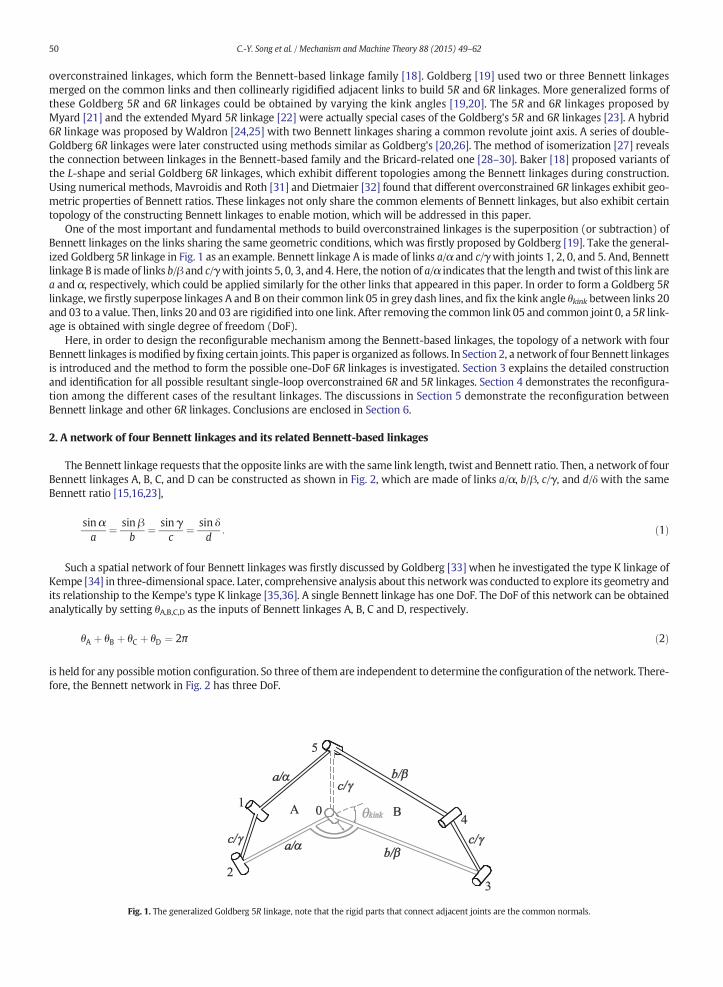
One of the most important and fundamental methods to build overconstrained linkages is the superposition (or subtraction) ofBennett linkages on the links sharing the same geometric conditions, which was firstly proposed by Goldberg [19]. Take the general-ized Goldberg 5R linkage in Fig. 1 as an example. Bennett linkage A is made of links a/α and c/γwith joints 1, 2, 0, and 5. And, Bennettlinkage B ismade of links b/β and c/γwith joints 5, 0, 3, and 4. Here, the notion of a/α indicates that the length and twist of this link area and α, respectively, which could be applied similarly for the other links that appeared in this paper. In order to form a Goldberg 5Rlinkage, we firstly superpose linkages A and B on their common link 05 in grey dash lines, and fix the kink angle θkink between links 20and 03 to a value. Then, links 20 and 03 are rigidified into one link. After removing the common link 05 and common joint 0, a 5R link-age is obtained with single degree of freedom (DoF).
Here, in order to design the reconfigurable mechanism among the Bennett-based linkages, the topology of a network with fourBennett linkages ismodified byfixing certain joints. This paper is organized as follows. In Section 2, a network of four Bennett linkagesis introduced and the method to form the possible one-DoF 6R linkages is investigated. Section 3 explains the detailed constructionand identification for all possible resultant single-loop overconstrained 6R and 5R linkages. Section 4 demonstrates the reconfigura-tion among the different cases of the resultant linkages. The discussions in Section 5 demonstrate the reconfiguration betweenBennett linkage and other 6R linkages. Conclusions are enclosed in Section 6.
2. A network of four Bennett linkages and its related Bennett-based linkages
The Bennett linkage requests that the opposite links arewith the same link length, twist and Bennett ratio. Then, a network of fourBennett linkages A, B, C, and D can be constructed as shown in Fig. 2, which are made of links a/α, b/β, c/γ, and d/δ with the sameBennett ratio [15,16,23],
sin αa
¼ sin βb
¼ sin γc
¼ sin δd
: ð1Þ
Such a spatial network of four Bennett linkages was firstly discussed by Goldberg [33] when he investigated the type K linkage ofKempe [34] in three-dimensional space. Later, comprehensive analysis about this networkwas conducted to explore its geometry andits relationship to the Kempe's type K linkage [35,36]. A single Bennett linkage has one DoF. The DoF of this network can be obtainedanalytically by setting θA,B,C,D as the inputs of Bennett linkages A, B, C and D, respectively.
θA þ θB þ θC þ θD ¼ 2π ð2Þ
is held for any possiblemotion configuration. So three of them are independent to determine the configuration of the network. There-fore, the Bennett network in Fig. 2 has three DoF.
Fig. 1. The generalized Goldberg 5R linkage, note that the rigid parts that connect adjacent joints are the common normals.
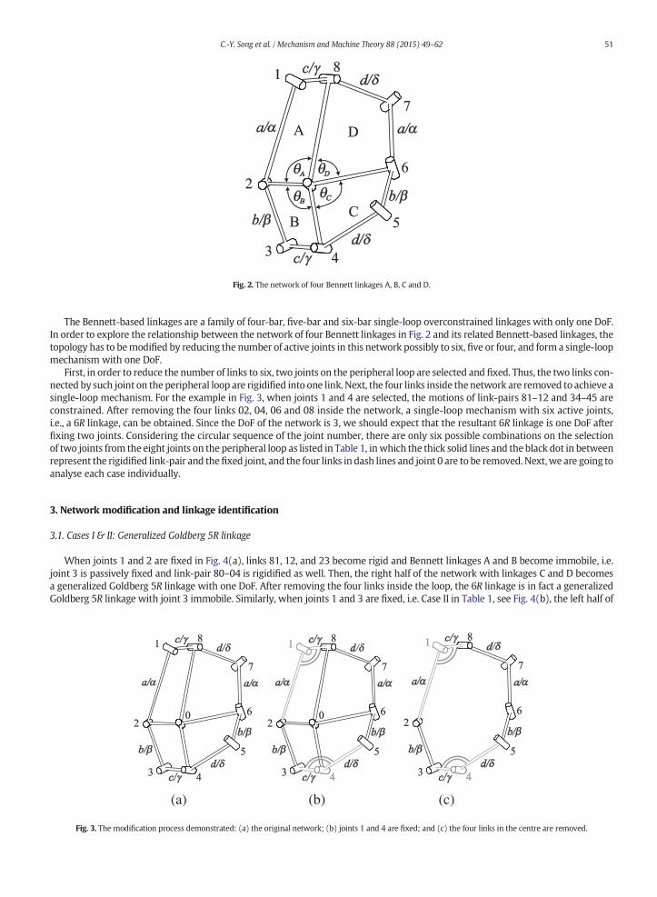
Fig. 2. The network of four Bennett linkages A, B, C and D.
51C.-Y. Song et al. / Mechanism and Machine Theory 88 (2015) 49–62
The Bennett-based linkages are a family of four-bar, five-bar and six-bar single-loop overconstrained linkages with only one DoF.In order to explore the relationship between the network of four Bennett linkages in Fig. 2 and its related Bennett-based linkages, thetopology has to bemodified by reducing the number of active joints in this network possibly to six, five or four, and form a single-loopmechanism with one DoF.
First, in order to reduce the number of links to six, two joints on the peripheral loop are selected and fixed. Thus, the two links con-nected by such joint on the peripheral loop are rigidified into one link. Next, the four links inside the network are removed to achieve asingle-loop mechanism. For the example in Fig. 3, when joints 1 and 4 are selected, the motions of link-pairs 81–12 and 34–45 areconstrained. After removing the four links 02, 04, 06 and 08 inside the network, a single-loop mechanism with six active joints,i.e., a 6R linkage, can be obtained. Since the DoF of the network is 3, we should expect that the resultant 6R linkage is one DoF afterfixing two joints. Considering the circular sequence of the joint number, there are only six possible combinations on the selectionof two joints from the eight joints on the peripheral loop as listed in Table 1, inwhich the thick solid lines and the black dot in betweenrepresent the rigidified link-pair and thefixed joint, and the four links in dash lines and joint 0 are to be removed.Next,we are going toanalyse each case individually.
3. Network modification and linkage identification
3.1. Cases I & II: Generalized Goldberg 5R linkage
When joints 1 and 2 are fixed in Fig. 4(a), links 81, 12, and 23 become rigid and Bennett linkages A and B become immobile, i.e.joint 3 is passively fixed and link-pair 80–04 is rigidified as well. Then, the right half of the network with linkages C and D becomesa generalized Goldberg 5R linkage with one DoF. After removing the four links inside the loop, the 6R linkage is in fact a generalizedGoldberg 5R linkage with joint 3 immobile. Similarly, when joints 1 and 3 are fixed, i.e. Case II in Table 1, see Fig. 4(b), the left half of
(a) (b) (c)
Fig. 3. The modification process demonstrated: (a) the original network; (b) joints 1 and 4 are fixed; and (c) the four links in the centre are removed.
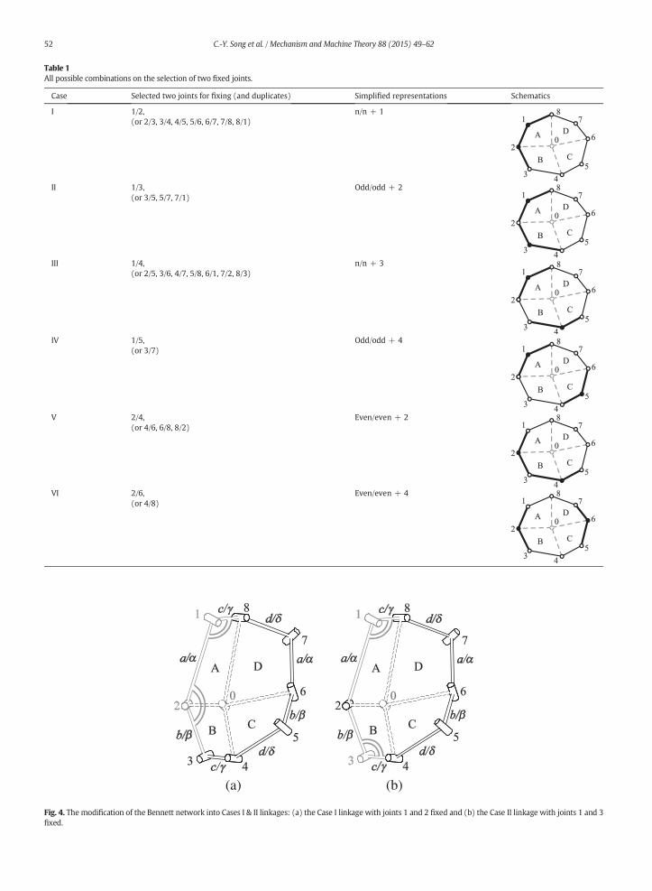
Table 1All possible combinations on the selection of two fixed joints.
Case Selected two joints for fixing (and duplicates) Simplified representations Schematics
I 1/2,(or 2/3, 3/4, 4/5, 5/6, 6/7, 7/8, 8/1)
n/n + 1
II 1/3,(or 3/5, 5/7, 7/1)
Odd/odd + 2
III 1/4,(or 2/5, 3/6, 4/7, 5/8, 6/1, 7/2, 8/3)
n/n + 3
IV 1/5,(or 3/7)
Odd/odd + 4
V 2/4,(or 4/6, 6/8, 8/2)
Even/even + 2
VI 2/6,(or 4/8)
Even/even + 4
(a) (b)
Fig. 4. The modification of the Bennett network into Cases I & II linkages: (a) the Case I linkage with joints 1 and 2 fixed and (b) the Case II linkage with joints 1 and 3fixed.
52 C.-Y. Song et al. / Mechanism and Machine Theory 88 (2015) 49–62
(a) (b)
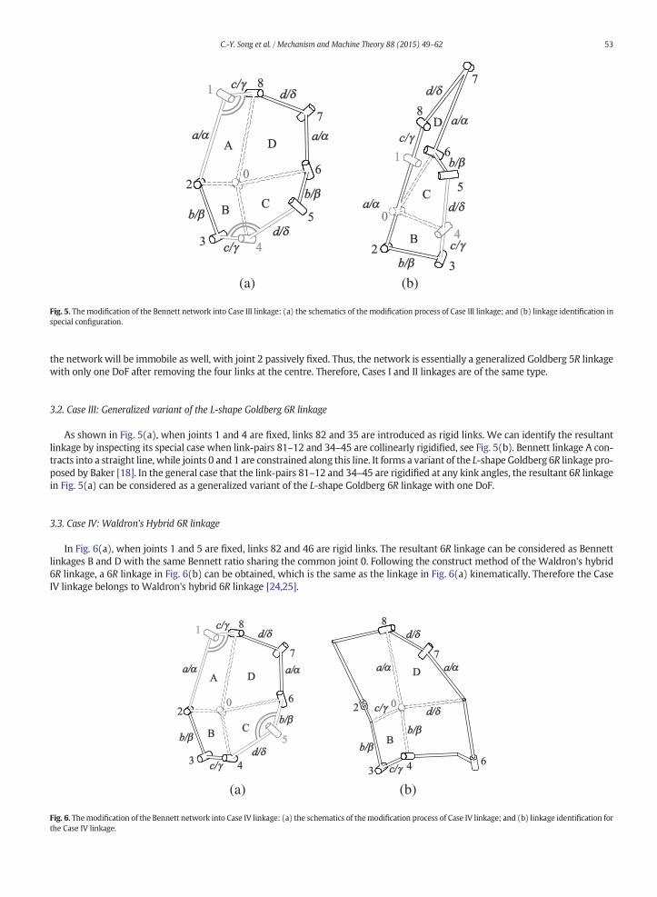
Fig. 5. Themodification of the Bennett network into Case III linkage: (a) the schematics of the modification process of Case III linkage; and (b) linkage identification inspecial configuration.
53C.-Y. Song et al. / Mechanism and Machine Theory 88 (2015) 49–62
the network will be immobile as well, with joint 2 passively fixed. Thus, the network is essentially a generalized Goldberg 5R linkagewith only one DoF after removing the four links at the centre. Therefore, Cases I and II linkages are of the same type.
3.2. Case III: Generalized variant of the L-shape Goldberg 6R linkage
As shown in Fig. 5(a), when joints 1 and 4 are fixed, links 82 and 35 are introduced as rigid links. We can identify the resultantlinkage by inspecting its special case when link-pairs 81–12 and 34–45 are collinearly rigidified, see Fig. 5(b). Bennett linkage A con-tracts into a straight line, while joints 0 and 1 are constrained along this line. It forms a variant of the L-shape Goldberg 6R linkage pro-posed by Baker [18]. In the general case that the link-pairs 81–12 and 34–45 are rigidified at any kink angles, the resultant 6R linkagein Fig. 5(a) can be considered as a generalized variant of the L-shape Goldberg 6R linkage with one DoF.
3.3. Case IV: Waldron's Hybrid 6R linkage
In Fig. 6(a), when joints 1 and 5 are fixed, links 82 and 46 are rigid links. The resultant 6R linkage can be considered as Bennettlinkages B and D with the same Bennett ratio sharing the common joint 0. Following the construct method of the Waldron's hybrid6R linkage, a 6R linkage in Fig. 6(b) can be obtained, which is the same as the linkage in Fig. 6(a) kinematically. Therefore the CaseIV linkage belongs to Waldron's hybrid 6R linkage [24,25].
(a) (b)
Fig. 6. Themodification of the Bennett network into Case IV linkage: (a) the schematics of themodification process of Case IV linkage; and (b) linkage identification forthe Case IV linkage.
(a) (b)
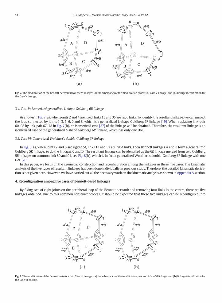
Fig. 7. The modification of the Bennett network into Case V linkage: (a) the schematics of the modification process of Case V linkage; and (b) linkage identification forthe Case V linkage.
54 C.-Y. Song et al. / Mechanism and Machine Theory 88 (2015) 49–62
3.4. Case V: Isomerized generalized L-shape Goldberg 6R linkage
As shown in Fig. 7(a), when joints 2 and 4 are fixed, links 13 and 35 are rigid links. To identify the resultant linkage, we can inspectthe loop connected by joints 1, 3, 5, 6, 0 and 8, which is a generalized L-shape Goldberg 6R linkage [19]. When replacing link-pair60–08 by link-pair 67–78 in Fig. 7(b), an isomerized case [27] of the linkage will be obtained. Therefore, the resultant linkage is anisomerized case of the generalized L-shape Goldberg 6R linkage, which has only one DoF.
3.5. Case VI: Generalized Wohlhart's double-Goldberg 6R linkage
In Fig. 8(a), when joints 2 and 6 are rigidified, links 13 and 57 are rigid links. Then Bennett linkages A and B form a generalizedGoldberg 5R linkage. So do the linkages C and D. The resultant linkage can be identified as the 6R linkage merged from two Goldberg5R linkages on common link 80 and 04, see Fig. 8(b), which is in fact a generalized Wohlhart's double-Goldberg 6R linkage with oneDoF [20].
In this paper, we focus on the geometric construction and reconfiguration among the linkages in these five cases. The kinematicanalysis of the five types of resultant linkages has been done individually in previous study. Therefore, the detailed kinematic deriva-tion is not given here. However, we have carried out all the necessarywork on the kinematic analysis as shown in Appendix A section.
4. Reconfiguration among five cases of Bennett-based linkages
By fixing two of eight joints on the peripheral loop of the Bennett network and removing four links in the centre, there are fivelinkages obtained. Due to this common construct process, it should be expected that these five linkages can be reconfigured into
(a) (b)
Fig. 8. Themodification of the Bennett network into Case VI linkage: (a) the schematics of themodification process of Case VI linkage; and (b) linkage identification forthe Case VI linkage.
(a) (b) (c)
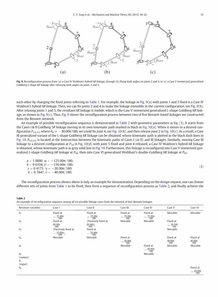
Fig. 9. Reconfiguration process from (a) a Case IVWaldron's hybrid 6R linkage, through (b) fixing kink angles on joints 2 and 4, to (c) a Case V isomerized generalizedGoldberg L-shape 6R linkage after releasing kink angles on joints 1 and 5.
55C.-Y. Song et al. / Mechanism and Machine Theory 88 (2015) 49–62
each other by changing the fixed joints referring to Table 1. For example, the linkage in Fig. 9(a) with joints 1 and 5 fixed is a Case IVWaldron's hybrid 6R linkage. Then, we can fix joints 2 and 4 to make the linkage immobile in the current configuration, see Fig. 9(b).After relaxing joints 1 and 5, the resultant 6R linkage is mobile, which is the Case V isomerized generalized L-shape Goldberg 6R link-age, as shown in Fig. 9(c). Thus, Fig. 9 shows the reconfiguration process between two of five Bennett-based linkages we constructedfrom the Bennett network.
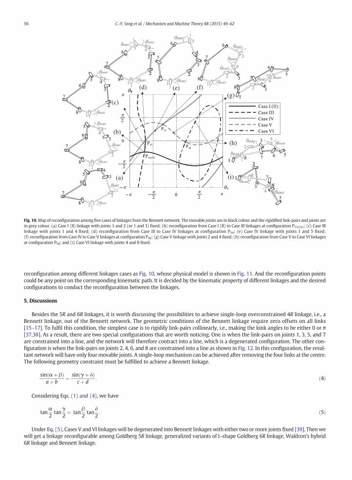
An example of possible reconfiguration sequence is demonstrated in Table 2 with geometric parameters as Eq. (3). It starts fromthe Cases I & II Goldberg 5R linkage moving in its own kinematic path marked in black in Fig. 10(a). When it moves to a desired con-figuration P13(23) where θ4=−30.00π/180, we could fix joint 4, see Fig. 10(b), and then release joint 2 in Fig. 10(c). As a result, a CaseIII generalized variant of the L-shape Goldberg 6R linkage can be obtained, whose kinematic path is plotted in the black dash lines inFig. 10. P13(23) is located at the intersection between the kinematic paths of Cases I (or II) and III linkages. Similarly, moving Case IIIlinkage to a desired configuration at P34 in Fig. 10(d) with joint 5 fixed and joint 4 released, a Case IV Waldron's hybrid 6R linkageis obtained, whose kinematic path is in grey solid line in Fig. 10. Furthermore, this linkage is reconfigured into Case V isomerized gen-eralized L-shape Goldberg 6R linkage at P45, then into Case VI generalized Wohlhart's double-Goldberg 6R linkage at P56.
Table 2An exam
Revol
θ1
θ2
θ3
θ4
θ5
θ6(outpθ7(inpuθ8
a ¼ 1:0000; α ¼ −125:00π=180;b ¼ 0:6104; β ¼ −150:00π=180;c ¼ 0:4175; γ ¼ −20:00π=180;d ¼ 0:7847; δ ¼ −40:00π=180:
ð3Þ
The reconfiguration process shown above is only an example for demonstration. Depending on the design request, one can choosedifferent sets of joints from Table 1 to be fixed, then form a sequence of reconfiguration process as Table 2, and finally achieve the
ple of reconfiguration sequence among all six possible linkage cases from the network of four Bennett linkages.
ute variables Case I Case II Case III Case IV Case V Case VI
Fixed at
− 75:00π180
Fixed at
− 75:00π180
Fixed at
− 75:00π180
Fixed at
− 75:00π180
Movable Movable
Fixed at84:68π180
(Passively fixed at84:68π180 )
Movable Movable Fixed at
− 26:24π180
(Passively fixed at
− 33:06π180 )
Fixed at
− 33:06π180
Movable
Movable Movable Fixed at
− 30:00π180
Fixed at40:00π180
Fixed at40:00π180
Movable Fixed at
− 90:00π180
Movable Movable
ut)Movable
t)Fixed at
− 20:00π180
(b)
(a)
(d) (e) (f)(g)
(c)
(h)
(i)
Fig. 10.Map of reconfiguration among five cases of linkages from the Bennett network. Themovable joints are in black colour and the rigidified link-pairs and joints arein grey colour. (a) Case I (II) linkage with joints 1 and 2 (or 1 and 3) fixed; (b) reconfiguration from Case I (II) to Case III linkages at configuration P13(23); (c) Case IIIlinkage with joints 1 and 4 fixed; (d) reconfiguration from Case III to Case IV linkages at configuration P34; (e) Case IV linkage with joints 1 and 5 fixed;(f) reconfiguration from Case IV to Case V linkages at configuration P45; (g) Case V linkagewith joints 2 and 4 fixed; (h) reconfiguration from Case V to Case VI linkagesat configuration P56; and (i) Case VI linkage with joints 4 and 8 fixed.
56 C.-Y. Song et al. / Mechanism and Machine Theory 88 (2015) 49–62
reconfiguration among different linkages cases as Fig. 10, whose physical model is shown in Fig. 11. And the reconfiguration pointscould be any point on the corresponding kinematic path. It is decided by the kinematic property of different linkages and the desiredconfigurations to conduct the reconfiguration between the linkages.
5. Discussions
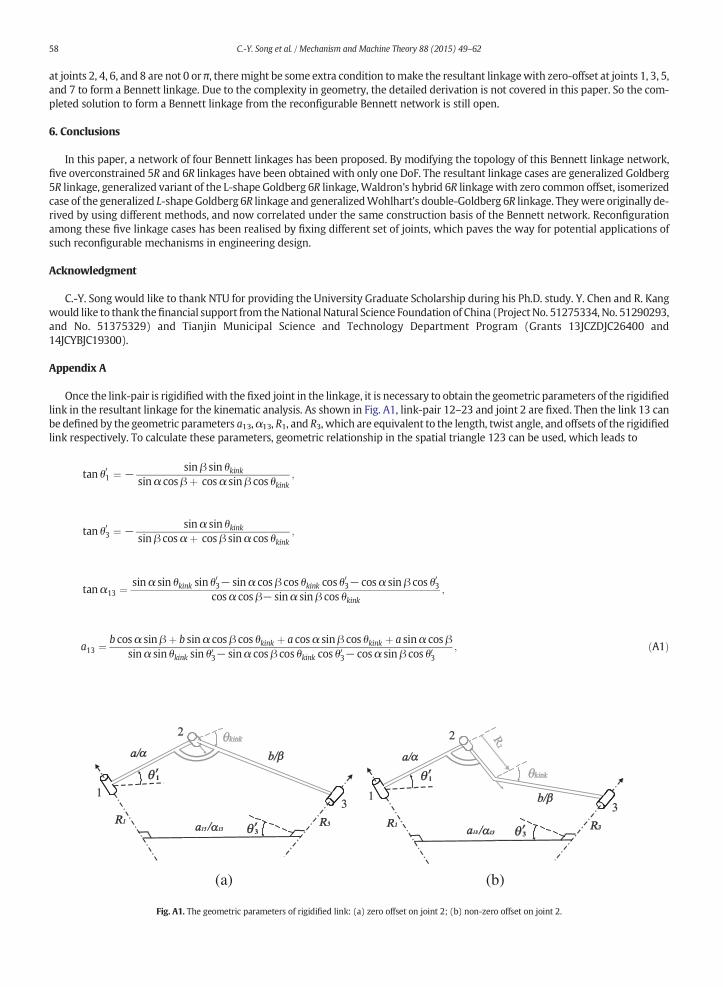
Besides the 5R and 6R linkages, it is worth discussing the possibilities to achieve single-loop overconstrained 4R linkage, i.e., aBennett linkage, out of the Bennett network. The geometric conditions of the Bennett linkage require zero offsets on all links[15–17]. To fulfil this condition, the simplest case is to rigidify link-pairs collinearly, i.e., making the kink angles to be either 0 or π[37,38]. As a result, there are two special configurations that are worth noticing. One is when the link-pairs on joints 1, 3, 5, and 7are constrained into a line, and the network will therefore contract into a line, which is a degenerated configuration. The other con-figuration is when the link-pairs on joints 2, 4, 6, and 8 are constrained into a line as shown in Fig. 12. In this configuration, the resul-tant networkwill have only fourmovable joints. A single-loopmechanism can be achieved after removing the four links at the centre.The following geometry constraint must be fulfilled to achieve a Bennett linkage.
sin α þ βð Þaþ b
¼ sin γ þ δð Þcþ d
: ð4Þ
Considering Eqs. (1) and (4), we have
tanα2tan
γ2¼ tan
β2tan
δ2: ð5Þ
Under Eq. (5), Cases V and VI linkageswill be degenerated into Bennett linkageswith either two ormore joints fixed [39]. Thenwewill get a linkage reconfigurable among Goldberg 5R linkage, generalized variants of L-shape Goldberg 6R linkage, Waldron's hybrid6R linkage and Bennett linkage.
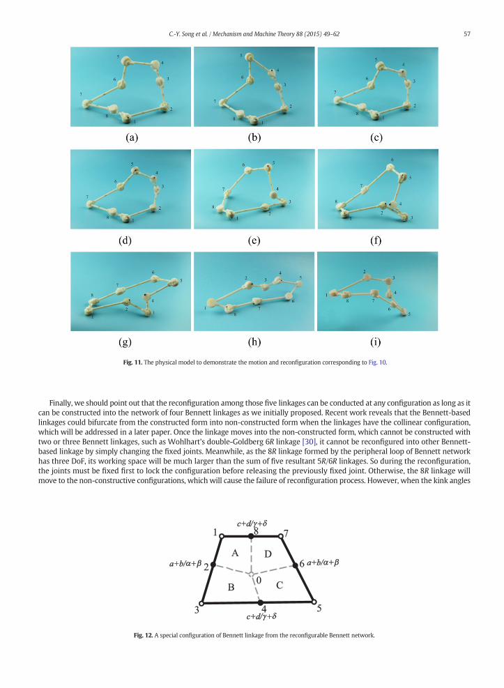
Fig. 11. The physical model to demonstrate the motion and reconfiguration corresponding to Fig. 10.
57C.-Y. Song et al. / Mechanism and Machine Theory 88 (2015) 49–62
Finally, we should point out that the reconfiguration among those five linkages can be conducted at any configuration as long as itcan be constructed into the network of four Bennett linkages as we initially proposed. Recent work reveals that the Bennett-basedlinkages could bifurcate from the constructed form into non-constructed form when the linkages have the collinear configuration,which will be addressed in a later paper. Once the linkage moves into the non-constructed form, which cannot be constructed withtwo or three Bennett linkages, such as Wohlhart's double-Goldberg 6R linkage [30], it cannot be reconfigured into other Bennett-based linkage by simply changing the fixed joints. Meanwhile, as the 8R linkage formed by the peripheral loop of Bennett networkhas three DoF, its working space will be much larger than the sum of five resultant 5R/6R linkages. So during the reconfiguration,the joints must be fixed first to lock the configuration before releasing the previously fixed joint. Otherwise, the 8R linkage willmove to the non-constructive configurations, which will cause the failure of reconfiguration process. However, when the kink angles
Fig. 12. A special configuration of Bennett linkage from the reconfigurable Bennett network.
58 C.-Y. Song et al. / Mechanism and Machine Theory 88 (2015) 49–62
at joints 2, 4, 6, and 8 are not 0 or π, theremight be some extra condition tomake the resultant linkagewith zero-offset at joints 1, 3, 5,and 7 to form a Bennett linkage. Due to the complexity in geometry, the detailed derivation is not covered in this paper. So the com-pleted solution to form a Bennett linkage from the reconfigurable Bennett network is still open.
6. Conclusions
In this paper, a network of four Bennett linkages has been proposed. By modifying the topology of this Bennett linkage network,five overconstrained 5R and 6R linkages have been obtained with only one DoF. The resultant linkage cases are generalized Goldberg5R linkage, generalized variant of the L-shape Goldberg 6R linkage,Waldron's hybrid 6R linkagewith zero common offset, isomerizedcase of the generalized L-shape Goldberg 6R linkage and generalizedWohlhart's double-Goldberg 6R linkage. Theywere originally de-rived by using different methods, and now correlated under the same construction basis of the Bennett network. Reconfigurationamong these five linkage cases has been realised by fixing different set of joints, which paves the way for potential applications ofsuch reconfigurable mechanisms in engineering design.
Acknowledgment
C.-Y. Song would like to thank NTU for providing the University Graduate Scholarship during his Ph.D. study. Y. Chen and R. Kangwould like to thank thefinancial support from theNational Natural Science Foundation of China (Project No. 51275334, No. 51290293,and No. 51375329) and Tianjin Municipal Science and Technology Department Program (Grants 13JCZDJC26400 and14JCYBJC19300).
Appendix A
Once the link-pair is rigidifiedwith the fixed joint in the linkage, it is necessary to obtain the geometric parameters of the rigidifiedlink in the resultant linkage for the kinematic analysis. As shown in Fig. A1, link-pair 12–23 and joint 2 are fixed. Then the link 13 canbe defined by the geometric parameters a13,α13, R1, and R3, which are equivalent to the length, twist angle, and offsets of the rigidifiedlink respectively. To calculate these parameters, geometric relationship in the spatial triangle 123 can be used, which leads to
tan θ01 ¼ − sin β sin θkinksin α cos β þ cos α sin β cos θkink
;
tan θ03 ¼ − sin α sin θkinksin β cos α þ cos β sin α cos θkink
;
tan α13 ¼ sin α sin θkink sin θ03− sin α cos β cos θkink cos θ03− cos α sin β cos θ03
cosα cos β− sinα sin β cos θkink;
a13 ¼ b cos α sin β þ b sin α cos β cos θkink þ a cos α sinβ cos θkink þ a sinα cos βsin α sin θkink sin θ03− sinα cos β cos θkink cos θ
03− cosα sin β cos θ03
; ðA1Þ
(a) (b)
Fig. A1. The geometric parameters of rigidified link: (a) zero offset on joint 2; (b) non-zero offset on joint 2.
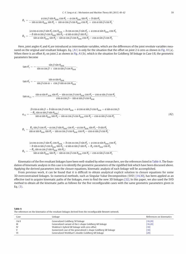
Table AThe refe
Case
I & IIIIIIVVVI
59C.-Y. Song et al. / Mechanism and Machine Theory 88 (2015) 49–62
R1 ¼ a cos β sin θkink cos θ03 þ a cos θkink sin θ03 þ b sin θ03
− sin α sin θkink sin θ03 þ sin α cos β cos θkink cos θ03 þ cos α sin β cos θ03
;
R3 ¼ða cos α cos β sin θ03 cos θkink þ b cosα cos β sin θ03 þ a cos α sin θkink cos θ
03
−b sinα sin β cos θkink sin θ03−a sinα sin β sin θ03Þsin α sin θkink sin θ03− sinα cos β cos θkink cos θ
03− cosα sin β cos θ03
:
Here, joint angles θ1′ and θ3′ are introduced as intermediate variables, which are the differences of the joint revolute variables mea-sured on the original and resultant linkages. Eq. (A1) is only for the situation that the offset on joint 2 is zero as shown in Fig. A1(a).When there is an offset R2 on joint 2 as shown in Fig. A1(b), which is the situation for Goldberg 5R linkage in Case I/II, the geometricparameters become
tan θ01 ¼ − sin β sin θkinksin α cos β þ cos α sin β cos θkink
;
tan θ03 ¼ − sin α sin θkinksin β cos α þ cos β sin α cos θkink
;
tan α13 ¼ sin α sin θ kink sin θ03− sinα cos β cos θkink cos θ03− cosα sin β cos θ03
cos α cos β− sin α sinβ cos θkink;
a13 ¼ðb cosα sin β þ b sinα cos β cos θkink þ a cosα sin β cos θkink þ a sin α cos β−R2 sinα sin β sin θkinkÞ
sin α sin θkink sin θ03− sin α cos β cos θkink cos θ03− cosα sin β cos θ03
; ðA2Þ
R1 ¼ R2 sin β cos θ03−a cos β sin θkink cos θ03−a cos θkink sin θ03−b sin θ03
sin α sin θkink sin θ03− sinα cos β cos θkink cos θ03− cosα sin β cos θ03
;
R3 ¼
ða cos α cos β sin θ03 cos θkink þ b cosα cos β sin θ03 þ a cos α sin θkink cos θ03
−b sinα sin β cos θkink sin θ03−a sinα sin β sin θ03 þ R2 cos θkink cos θ03
−R2 sin α cos β sin θkink sin θ03Þsin α sin θkink sin θ03− sinα cos β cos θkink cos θ
03− cosα sin β cos θ03
:
Kinematics of thefive resultant linkages have beenwell-studied by other researchers, see the references listed in Table A. The foun-dation of kinematic analysis in this case is to identify the geometric parameters of the rigidified linkwhich have been discussed above.Applying the derived parameters into the closure equations, kinematic analysis of each linkage will be accomplished.
From previous work, it can be found that it is difficult to obtain analytical explicit solution to closure equations for some3D overconstrained linkages. So numerical methods, such as Singular Value Decomposition (SVD) [14,30], has been applied as aneffective tool to acquire kinematic paths of the linkages, even to find the new 3D linkages [32]. In this paper, we also used the SVDmethod to obtain all the kinematic paths as follows for the five reconfigurable cases with the same geometric parameters given inEq. (3).
rences on the kinematics of the resultant linkages derived from the reconfigurable Bennett network.
Linkage References on kinematics
Generalized Goldberg 5R linkage [18,20]Generalized variant of the L-shape Goldberg 6R linkage [18,20]Waldron's hybrid 6R linkage with zero offset [18]Isomerized case of the generalized L-shape Goldberg 6R linkage [18]Generalized Wohlhart's double-Goldberg 6R linkage [20]
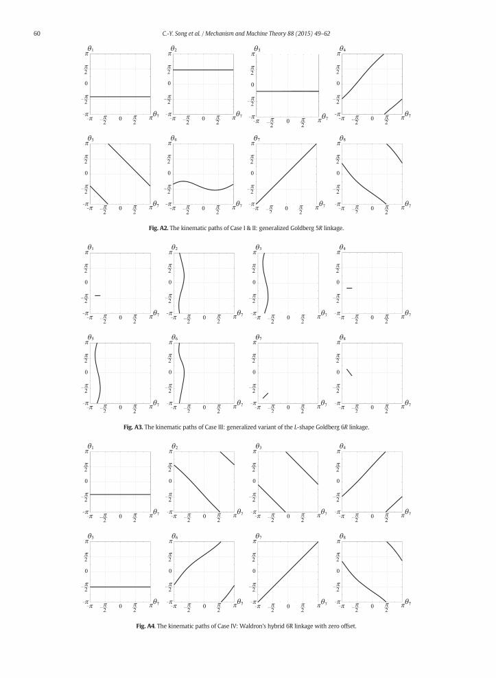
Fig. A2. The kinematic paths of Case I & II: generalized Goldberg 5R linkage.
Fig. A3. The kinematic paths of Case III: generalized variant of the L-shape Goldberg 6R linkage.
Fig. A4. The kinematic paths of Case IV: Waldron's hybrid 6R linkage with zero offset.
60 C.-Y. Song et al. / Mechanism and Machine Theory 88 (2015) 49–62
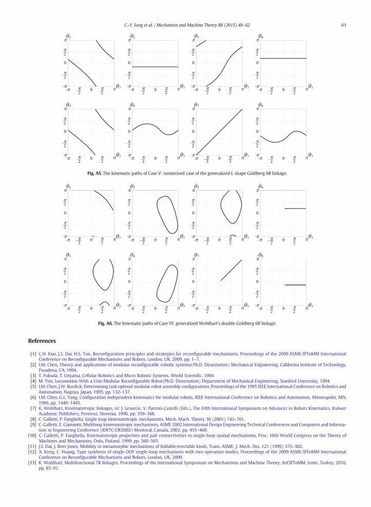
Fig. A5. The kinematic paths of Case V: isomerized case of the generalized L-shape Goldberg 6R linkage.
Fig. A6. The kinematic paths of Case VI: generalized Wohlhart's double-Goldberg 6R linkage.
61C.-Y. Song et al. / Mechanism and Machine Theory 88 (2015) 49–62
References
[1] C.H. Kuo, J.S. Dai, H.S. Yan, Reconfiguration principles and strategies for reconfigurable mechanisms, Proceedings of the 2009 ASME/IFToMM InternationalConference on Reconfigurable Mechanisms and Robots, London, UK, 2009, pp. 1–7.
[2] I.M. Chen, Theory and applications of modular reconfigurable robotic systems(Ph.D. Dissertation) Mechanical Engineering, California Institute of Technology,Pasadena, CA, 1994.
[3] T. Fukuda, T. Ueyama, Cellular Robotics and Micro Robotic Systems, World Scientific, 1994.[4] M. Yim, Locomotion With a Unit-Modular Reconfigurable Robot(Ph.D. Dissertation) Department of Mechanical Engineering, Stanford University, 1994.[5] I.M. Chen, J.W. Burdick, Determining task optimal modular robot assembly configurations, Proceedings of the 1995 IEEE International Conference on Robotics and
Automation, Nagoya, Japan, 1995, pp. 132–137.[6] I.M. Chen, G.L. Yang, Configuration independent kinematics for modular robots, IEEE International Conference on Robotics and Automation, Minneapolis, MN,
1996, pp. 1440–1445.[7] K. Wohlhart, Kinematotropic linkages, in: J. Lenarcic, V. Parenti-Castelli (Eds.), The Fifth International Symposium on Advances in Robots Kinematics, Kulwer
Academic Publishers, Portoroz, Slovenia, 1996, pp. 359–368.[8] C. Galletti, P. Fanghella, Single-loop kinematotropic mechanisms, Mech. Mach. Theory 36 (2001) 743–761.[9] C. Galletti, E. Giannotti, Multiloop kinematotropic mechanisms, ASME 2002 International Design Engineering Technical Conferences and Computers and Informa-
tion in Engineering Conference (IDETC/CIE2002) Montreal, Canada, 2002, pp. 455–460.[10] C. Galletti, P. Fanghella, Kinematotropic properties and pair connectivities in single-loop spatial mechanisms, Proc. 10th World Congress on the Theory of
Machines and Mechanisms, Oulu, Finland, 1999, pp. 560–565.[11] J.S. Dai, J. Rees Jones, Mobility in metamorphic mechanisms of foldable/erectable kinds, Trans. ASME: J. Mech. Des. 121 (1999) 375–382.[12] X. Kong, C. Huang, Type synthesis of single-DOF single-loop mechanisms with two operation modes, Proceedings of the 2009 ASME/IFToMM International
Conference on Reconfigurable Mechanisms and Robots, London, UK, 2009.[13] K. Wohlhart, Multifunctional 7R linkages, Proceedings of the International Symposium on Mechanisms and Machine Theory, AzCIFToMM, Izmir, Turkey, 2010,
pp. 85–91.
62 C.-Y. Song et al. / Mechanism and Machine Theory 88 (2015) 49–62
[14] C.Y. Song, Y. Chen, Multiple linkage forms and bifurcation behaviours of the double-subtractive-Goldberg linkage, Mech. Mach. Theory 57 (2012) 95–110.[15] G.T. Bennett, A new mechanism, Engineering 76 (1903) 777–778.[16] G.T. Bennett, The skew isogram mechanism, Proc. Lond. Math. Soc. s2-13 (1914) 151–173.[17] M. Savage, Four-link mechanisms with cylindric, revolute and prismatic pairs, Mech. Mach. Theory 7 (1972) 191–208.[18] J.E. Baker, A comparative survey of the Bennett-based, 6-revolute kinematic loops, Mech. Mach. Theory 28 (1993) 83–96.[19] M. Goldberg, New five-bar and six-bar linkages in three dimensions, Trans. ASME 65 (1943) 649–663.[20] K. Wohlhart, Merging two general goldberg 5R linkages to obtain a new 6R space mechanism, Mech. Mach. Theory 26 (1991) 659–668.[21] F.E. Myard, Contribution à la géométrie des systèmes articulés, Bull. Soc. Math. Fr. 59 (1931) 183–210.[22] Y. Chen, Z. You, An extended Myard linkage and its derived 6R linkage, Trans. ASME: J. Mech. Des. 130 (2008) 8.[23] J.E. Baker, The Bennett, Goldberg and Myard linkages — in perspective, Mech. Mach. Theory 14 (1979) 239–253.[24] K.J. Waldron, Hybrid overconstrained linkages, J. Mech. 3 (1968) 73–78.[25] K.J. Waldron, Symmetric overconstrained linkages, Trans. ASME: J. Eng. Ind. 91 (1969) 158–164.[26] Y. Chen, Z. You, Spatial 6R linkages based on the combination of two Goldberg 5R linkages, Mech. Mach. Theory 42 (2007) 1484–1498.[27] K. Wohlhart, On isomeric overconstrained space mechanisms, Proceedings of the Eights World Congress on the Theory of Machines and Mechanisms, Prague,
Czechoslovakia, 1991, pp. 153–158.[28] R. Bricard, Mémoire sur la théorie de l'octaèdre articulé, J. Pure Appl. Math. 3 (1897) 113–150.[29] R. Bricard, Leçons de cinématique, Gauthier-Villars, Paris, 1927.[30] C.Y. Song, Y. Chen, I.M. Chen, A 6R linkage reconfigurable between the line-symmetric Bricard linkage and the Bennett linkage,Mech.Mach. Theory 70 (2013) 278–282.[31] C. Mavroidis, B. Roth, Analysis and synthesis of overconstrained mechanisms, ASME Design Technical Conferences, Minneapolis, MI, 1994, pp. 115–133.[32] P. Dietmaier, A new 6R space mechanism, Proceeding 9th World Congress IFToMM, Milano, Italy, 1995, pp. 52–56.[33] M. Goldberg, A three-dimensional analog of a plane Kempe linkage, J. Math. Phys. 25 (1946) 96–110.[34] A. Kempe, On conjugate four-piece linkages, Proc. Lond. Math. Soc. 1 (1877) 133–149.[35] J.E. Baker, An analysis of Goldberg's anconoidal linkage, Mech. Mach. Theory 18 (1983) 371–376.[36] H.C. Yu, J.E. Baker, On the generation of new linkages from Bennett loops, Mech. Mach. Theory 16 (1981) 473–485.[37] A.T. Yang, Application of Quaternion Algebra and Dual Numbers to the Analysis of Spatial Mechanisms(Ph.D. Dissertation) Columbia University, 1963.[38] C. Mavroidis, B. Roth, On the Geometry of Spatial Polygons and Screw Polygons, Trans. ASME: J. Mech. Des. 119 (1997) 246–252.[39] C.Y. Song, Y. Chen, A Special Wohlhart's Double-Goldberg 6R Linkage and its Multiple Operation Forms Among 4R and 6R Linkages, Advances in Reconfigurable
Mechanisms and Robots I, Springer, London, 2012. 45–52.