mechanical performance of glass and carbon/vinyl ester...
TRANSCRIPT
American Institute of Aeronautics and Astronautics
1
Mechanical Performance of Glass and Carbon/Vinyl Ester Composites for Marine Structures
Gowthaman Swaminathan* Graduate Research Assistant, Greensboro, NC, 27411
and
Kunigal Shivakumar† Research Professor, Greensboro, NC, 27411
This paper describes the processing and mechanical characterization of two different fibers (glass and carbon) and two different fabric architectures (woven roving and stitch bonded) that were made into composites using Dow Chemical’s Derakane 510A-40, a brominated vinyl ester resin. Both E-glass and T700 carbon fibers were coated with vinyl ester compatible sizing. Composite panels were fabricated by vacuum assisted resin transfer molding (VARTM), specimens were machined, and mechanical tests were conducted as per the accepted test standards. Tension, compression, in-plane shear and inter-laminar shear properties were measured and their associated failure modes were compared with each other. The specific properties of the composites were compared with that of steel.
I. Introduction In a number of Naval ship programs, fiber reinforced polymer matrix composites have been considered because
of their light weight, high strength, corrosion resistance, and potential for very low maintenance cost over their life of operation. E-glass (GL) woven roving fabric and vinyl ester (VE) resin are commonly used in marine structures because of low cost and resistance to seawater environment. The woven roven technology has number of limitations, namely 1) crimping of yarns that causes stress concentration points at the yarns’ cross-over and a subsequent knockdown in strength [1]; 2) increased fiber misalignment angle that reduces the compression strength by as much as 20% [2]; and 3) uneven woven surface that allow resin to pool among the roving yarn making sites for failure initiation [3]. More importantly, even though the specific strength of glass composites is about two and half times that of steel, its specific stiffness is only about half that of steel (see Table 1, the data from ref. 4). The marine top structures are stiffness critical from the ship’s stability point of view and the hull structures are strength critical. Therefore, the composite material must have at least same or better specific stiffness than marine steel for it to be considered for top structures.
To overcome the above limitations, a number of advances have been made in the manufacturing of fabric system and cost reduction of carbon fiber. Advances in fabric manufacturing technologies are yielding multi-layered and multi-axial fabrics called Stitch Bonded or Knitmat. They are directionally oriented structures and can be engineered to enhance the in-plane properties [5]. A number of multi-layered yarns are placed in required orientations and knitted by polyester thread, and then the stack is hot pressed to keep the fibers undisturbed during transportation and handling. Lay-ups of 0/90, 0/±45, 0/±45/90, ±45/90/0 or 0/60/-60 are commonly available from the supplier. Benefits of these types of fabric are better mechanical properties, reduced fiber misalignment, excellent tear resistance, improved degree of drapability, reduced manual labor and human errors, improved inter-laminar properties by through-the-thickness knitting, less waste factor and affordable total cost factor [6]. Toray Corporation has developed a less expensive grade of PAN carbon fibers for different applications. It has also developed a special sizing (FOE) to improve adhesion properties of T700 carbon fibers to vinyl ester resin.
* Graduate Research Assistant, Center for Composite Materials Research, Department of Mechanical and Chemical Engineering, 205 Fort IRC, 1601 E Market Street, Greensboro, NC 27411 † Director and Research Professor, Center for Composite Materials Research, Department of Mechanical and Chemical Engineering, 205 Fort IRC, 1601 E Market Street, Greensboro, NC 27411, AIAA Associate Fellow
American Institute of Aeronautics and Astronautics
2
II. Objective The objective of this paper is to fabricate glass and T700 carbon fibers and vinyl ester matrix composites through
a manufacturing process recommended for marine applications, measure specific properties of these composites and then compare them with marine steel.
III. Materials Two different fibers, namely, glass and carbon fibers and two different fabric architectures, namely, woven
roving and 0/90 stitch bonded (or Knitmat) were studied. The resin system used was Dow Chemical’s Derakane 510A-40. Details of these materials are given below.
A. Glass Fibers A combination of good mechanical properties and relatively low cost makes glass fiber attractive choice for the
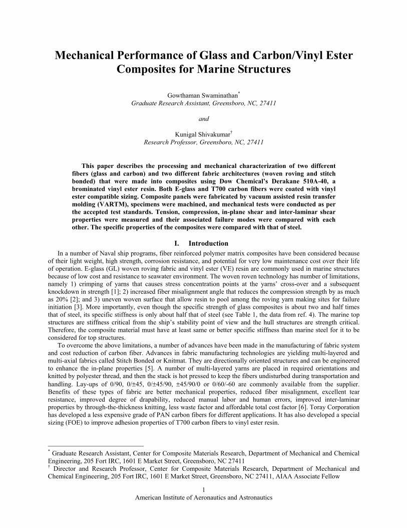
marine structures. The glass fiber chosen was E-glass, a most common type used in composites. The woven roving (Rovcloth) was chosen as one of the fabrics because of its wide use in boat construction. The fabric is an inexpensive way to apply a large quantity of glass in one ply. Rovcloth 1854 [7] consists of single end glass rovings with Fiber Glass Industries’ (FGI) Super 317 sizing for ease of handling, fast wet out, and compatibility with a number of resins including vinyl ester. The areal weight was 610 gm/sqm (18 oz/sqyd) and the construction was unbalanced [5] with 59% of the fibers in the warp direction and the remaining 41% of the fibers in the fill direction. This ratio was verified by the pic count (i.e. the number of rovings per inch). The pic count was 5 in the warp direction and 3.5 in the fill direction. This fabric was supplied by Fiber Glass Industries with the designation of FGI-1854 and its architecture is shown in Figure 1.
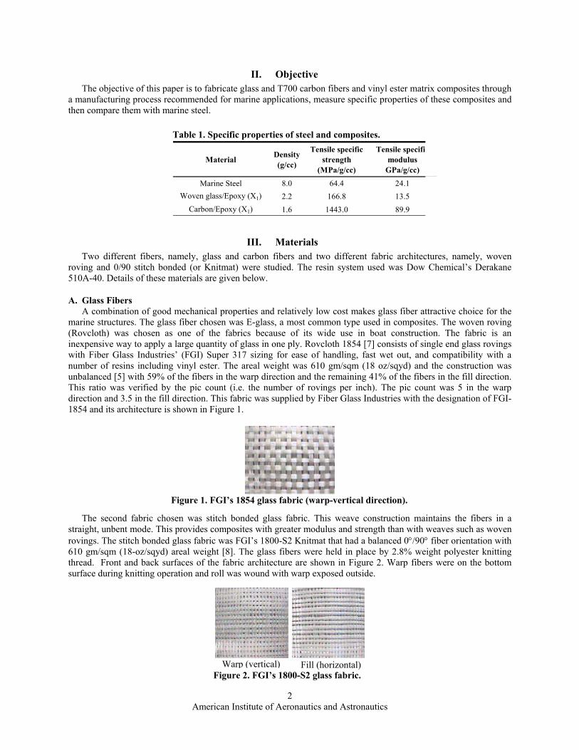
The second fabric chosen was stitch bonded glass fabric. This weave construction maintains the fibers in a
straight, unbent mode. This provides composites with greater modulus and strength than with weaves such as woven rovings. The stitch bonded glass fabric was FGI’s 1800-S2 Knitmat that had a balanced 0°/90° fiber orientation with 610 gm/sqm (18-oz/sqyd) areal weight [8]. The glass fibers were held in place by 2.8% weight polyester knitting thread. Front and back surfaces of the fabric architecture are shown in Figure 2. Warp fibers were on the bottom surface during knitting operation and roll was wound with warp exposed outside.
Table 1. Specific properties of steel and composites.
Material Density(g/cc)
Tensile specific strength
(MPa/g/cc)
Tensile specifimodulus
GPa/g/cc)
Marine Steel 8.0 64.4 24.1Woven glass/Epoxy (X1) 2.2 166.8 13.5
Carbon/Epoxy (X1) 1.6 1443.0 89.9
Figure 1. FGI’s 1854 glass fabric (warp-vertical direction).
Figure 2. FGI’s 1800-S2 glass fabric.
Warp (vertical) Fill (horizontal)
American Institute of Aeronautics and Astronautics
3
B. Carbon Fibers The carbon stitch bonded fabric designated by LT650-C10-R2VE was supplied by Devold AMT AS, Sweden.
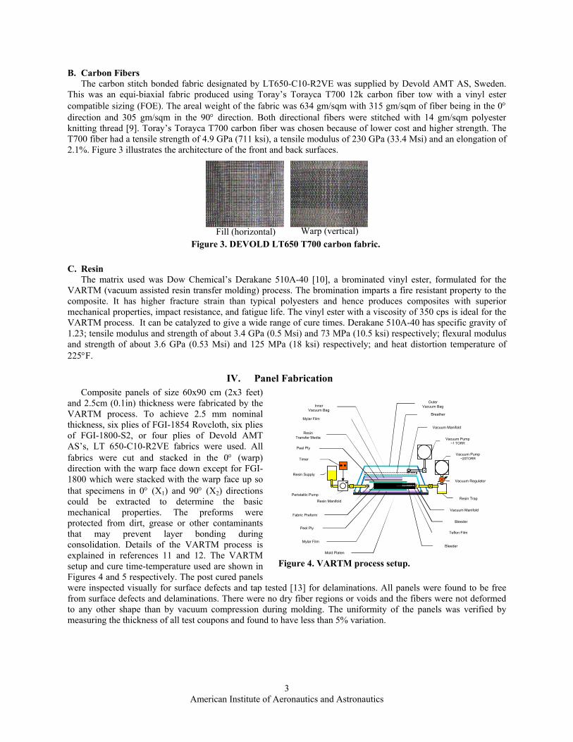
This was an equi-biaxial fabric produced using Toray’s Torayca T700 12k carbon fiber tow with a vinyl ester compatible sizing (FOE). The areal weight of the fabric was 634 gm/sqm with 315 gm/sqm of fiber being in the 0° direction and 305 gm/sqm in the 90° direction. Both directional fibers were stitched with 14 gm/sqm polyester knitting thread [9]. Toray’s Torayca T700 carbon fiber was chosen because of lower cost and higher strength. The T700 fiber had a tensile strength of 4.9 GPa (711 ksi), a tensile modulus of 230 GPa (33.4 Msi) and an elongation of 2.1%. Figure 3 illustrates the architecture of the front and back surfaces.
C. Resin The matrix used was Dow Chemical’s Derakane 510A-40 [10], a brominated vinyl ester, formulated for the
VARTM (vacuum assisted resin transfer molding) process. The bromination imparts a fire resistant property to the composite. It has higher fracture strain than typical polyesters and hence produces composites with superior mechanical properties, impact resistance, and fatigue life. The vinyl ester with a viscosity of 350 cps is ideal for the VARTM process. It can be catalyzed to give a wide range of cure times. Derakane 510A-40 has specific gravity of 1.23; tensile modulus and strength of about 3.4 GPa (0.5 Msi) and 73 MPa (10.5 ksi) respectively; flexural modulus and strength of about 3.6 GPa (0.53 Msi) and 125 MPa (18 ksi) respectively; and heat distortion temperature of 225°F.
IV. Panel Fabrication Composite panels of size 60x90 cm (2x3 feet)
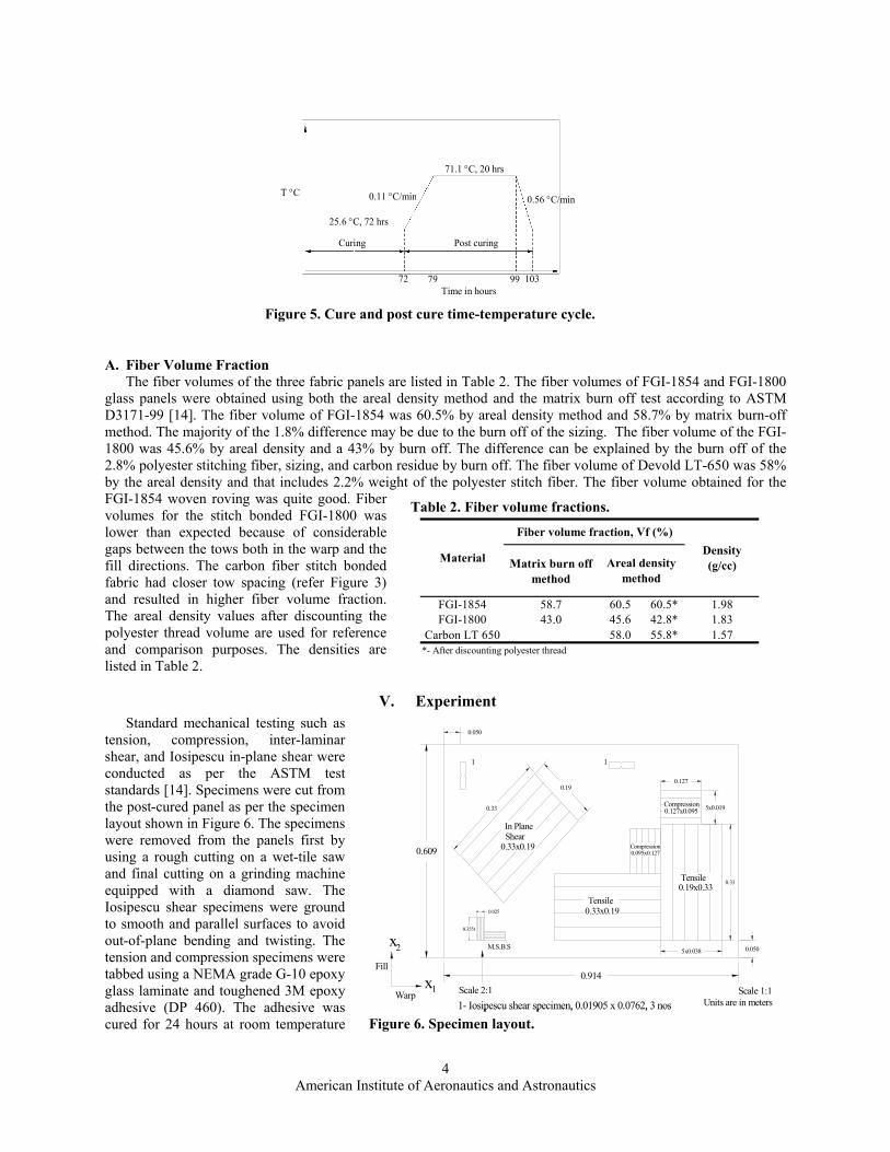
and 2.5cm (0.1in) thickness were fabricated by the VARTM process. To achieve 2.5 mm nominal thickness, six plies of FGI-1854 Rovcloth, six plies of FGI-1800-S2, or four plies of Devold AMT AS’s, LT 650-C10-R2VE fabrics were used. All fabrics were cut and stacked in the 0° (warp) direction with the warp face down except for FGI-1800 which were stacked with the warp face up so that specimens in 0° (X1) and 90° (X2) directions could be extracted to determine the basic mechanical properties. The preforms were protected from dirt, grease or other contaminants that may prevent layer bonding during consolidation. Details of the VARTM process is explained in references 11 and 12. The VARTM setup and cure time-temperature used are shown in Figures 4 and 5 respectively. The post cured panels were inspected visually for surface defects and tap tested [13] for delaminations. All panels were found to be free from surface defects and delaminations. There were no dry fiber regions or voids and the fibers were not deformed to any other shape than by vacuum compression during molding. The uniformity of the panels was verified by measuring the thickness of all test coupons and found to have less than 5% variation.
Figure 3. DEVOLD LT650 T700 carbon fabric.
Fill (horizontal) Warp (vertical)
Resin Supply
Timer
Peristaltic Pump
Resin Manifold
Mold Platen
Mylar Film
Peel Ply
Fabric PreformVacuum Manifold
Resin Trap
Vacuum Regulator
Vacuum Pump~20TORR
Vacuum Pump~1 TORR
Bleeder
Teflon Film
Breather
InnerVacuum Bag
Mylar Film
Bleeder
Peel Ply
OuterVacuum Bag
ResinTransfer Media
Vacuum Manifold
Figure 4. VARTM process setup.
American Institute of Aeronautics and Astronautics
4
A. Fiber Volume Fraction The fiber volumes of the three fabric panels are listed in Table 2. The fiber volumes of FGI-1854 and FGI-1800
glass panels were obtained using both the areal density method and the matrix burn off test according to ASTM D3171-99 [14]. The fiber volume of FGI-1854 was 60.5% by areal density method and 58.7% by matrix burn-off method. The majority of the 1.8% difference may be due to the burn off of the sizing. The fiber volume of the FGI-1800 was 45.6% by areal density and a 43% by burn off. The difference can be explained by the burn off of the 2.8% polyester stitching fiber, sizing, and carbon residue by burn off. The fiber volume of Devold LT-650 was 58% by the areal density and that includes 2.2% weight of the polyester stitch fiber. The fiber volume obtained for the FGI-1854 woven roving was quite good. Fiber volumes for the stitch bonded FGI-1800 was lower than expected because of considerable gaps between the tows both in the warp and the fill directions. The carbon fiber stitch bonded fabric had closer tow spacing (refer Figure 3) and resulted in higher fiber volume fraction. The areal density values after discounting the polyester thread volume are used for reference and comparison purposes. The densities are listed in Table 2.
V. Experiment Standard mechanical testing such as
tension, compression, inter-laminar shear, and Iosipescu in-plane shear were conducted as per the ASTM test standards [14]. Specimens were cut from the post-cured panel as per the specimen layout shown in Figure 6. The specimens were removed from the panels first by using a rough cutting on a wet-tile saw and final cutting on a grinding machine equipped with a diamond saw. The Iosipescu shear specimens were ground to smooth and parallel surfaces to avoid out-of-plane bending and twisting. The tension and compression specimens were tabbed using a NEMA grade G-10 epoxy glass laminate and toughened 3M epoxy adhesive (DP 460). The adhesive was cured for 24 hours at room temperature
T °C
25.6 °C, 72 hrs
Time in hours
Curing Post curing
0.11 °C/min 0.56 °C/min
71.1 °C, 20 hrs
72 79 99 103
Figure 5. Cure and post cure time-temperature cycle.
0.609
5x0.038
0.33
0.127
5x0.019
0.025
Tensile 0.33x0.19
Compression0.127x0.095
Compression0.095x0.127
0.050
0.050
Tensile0.19x0.33
Fill
x
0.914xWarp
M.S.B.S
Scale 2:1 Scale 1:1
0.33x0.19
In Plane Shear
0.19
0.33
2
1Units are in meters
0.355t
1- Iosipescu shear specimen, 0.01905 x 0.0762, 3 nos
1 1
0.609
5x0.038
0.33
0.127
5x0.019
0.025
Tensile 0.33x0.19
Compression0.127x0.095
Compression0.095x0.127
0.050
0.050
Tensile0.19x0.33
Fill
x
0.914xWarp
M.S.B.S
Scale 2:1 Scale 1:1
0.33x0.19
In Plane Shear
0.19
0.33
2
1Units are in meters
0.355t
1- Iosipescu shear specimen, 0.01905 x 0.0762, 3 nos
0.609
5x0.038
0.33
0.127
5x0.019
0.025
Tensile 0.33x0.19
Compression0.127x0.095
Compression0.095x0.127
0.050
0.050
Tensile0.19x0.33
Fill
x
0.914xWarp
M.S.B.S
Scale 2:1 Scale 1:1
0.33x0.19
In Plane Shear
0.19
0.33
2
1Units are in meters
0.355t
1- Iosipescu shear specimen, 0.01905 x 0.0762, 3 nos
1 1
Figure 6. Specimen layout.
Table 2. Fiber volume fractions.
Matrix burn offmethod
FGI-1854 58.7 60.5 60.5* 1.98FGI-1800 43.0 45.6 42.8* 1.83
Carbon LT 650 58.0 55.8* 1.57*- After discounting polyester thread
Material Density(g/cc)
Fiber volume fraction, Vf (%)
Areal densitymethod
American Institute of Aeronautics and Astronautics
5
within a vacuum bag at 29 in Hg. All mechanical tests were conducted on a MTS Uniaxial Testing Machine using mechanical grips. Tension, compression, ILSS and Iosipescu shear tests were conducted in both X1 and X2 directions. Five specimens were tested in each condition. Three specimens were tested Iosipescu shear properties in each direction. All axial strains were measured by extensometer and transverse strains by strain gages. Strain gages were attached as follows:
(i) Tension: Three out of five specimens were strain gaged in transverse direction for Poisson’s ratio (ii) Compression: One out of five was strain gaged in axial direction, because of small gage length for
compression modulus (iii) Iosipescu in-plane shear: All three strain gage elements are placed at ±45° to the loading axis, in the middle
of the specimen (away from the notches) and along the loading axis to measure the shear response.
A. Tension Test Tests were conducted according to ASTM Standard Test Method (D 3039/D 3039M-00) for Tensile Properties
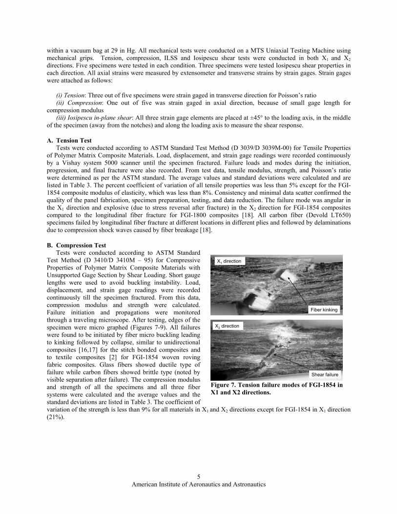
of Polymer Matrix Composite Materials. Load, displacement, and strain gage readings were recorded continuously by a Vishay system 5000 scanner until the specimen fractured. Failure loads and modes during the initiation, progression, and final fracture were also recorded. From test data, tensile modulus, strength, and Poisson’s ratio were determined as per the ASTM standard. The average values and standard deviations were calculated and are listed in Table 3. The percent coefficient of variation of all tensile properties was less than 5% except for the FGI-1854 composite modulus of elasticity, which was less than 8%. Consistency and minimal data scatter confirmed the quality of the panel fabrication, specimen preparation, testing, and data reduction. The failure mode was angular in the X1 direction and explosive (due to stress reversal after fracture) in the X2 direction for FGI-1854 composites compared to the longitudinal fiber fracture for FGI-1800 composites [18]. All carbon fiber (Devold LT650) specimens failed by longitudinal fiber fracture at different locations in different plies and followed by delaminations due to compression shock waves caused by fiber breakage [18].
B. Compression Test Tests were conducted according to ASTM Standard
Test Method (D 3410/D 3410M – 95) for Compressive Properties of Polymer Matrix Composite Materials with Unsupported Gage Section by Shear Loading. Short gauge lengths were used to avoid buckling instability. Load, displacement, and strain gage readings were recorded continuously till the specimen fractured. From this data, compression modulus and strength were calculated. Failure initiation and propagations were monitored through a traveling microscope. After testing, edges of the specimen were micro graphed (Figures 7-9). All failures were found to be initiated by fiber micro buckling leading to kinking followed by collapse, similar to unidirectional composites [16,17] for the stitch bonded composites and to textile composites [2] for FGI-1854 woven roving fabric composites. Glass fibers showed ductile type of failure while carbon fibers showed brittle type (noted by visible separation after failure). The compression modulus and strength of all the specimens and all three fiber systems were calculated and the average values and the standard deviations are listed in Table 3. The coefficient of variation of the strength is less than 9% for all materials in X1 and X2 directions except for FGI-1854 in X1 direction (21%).
X1 direction
X2 direction
Fiber kinking
Shear failure
X1 direction
X2 direction
Fiber kinking
Shear failure
Figure 7. Tension failure modes of FGI-1854 in X1 and X2 directions.

American Institute of Aeronautics and Astronautics
6
C. In-Plane Shear Test 1. IOSIPESCU TEST
This test was based on the effect that a shear force transmitted through a section between two edge notches will produce a nearly uniform stress across the section. Tests were conducted on an Iosipescu test fixture supported by Wyaming. Load, displacement, and strain gage readings were recorded continuously until the specimen failed. From this data, shear modulus from the initial slope of shear stress versus shear strain plot and 0.2% offset shear strength were determined. The strain gages went off-scale at around 1.8% shear strain and hence the shear strength at 5% shear strain was not determined. Failure modes were recorded and the pictures of failed sections are shown in Figures 10-12. All failures occurred in the notch section that is indicated by white lines for carbon fiber composite and white region for glass fiber composites in the figures. The average and standard deviation of shear modulus and 0.2% offset shear strength were calculated and are listed in Table 3. The data scatter is acceptable.
X1 direction
X2 direction
Fiber kinking
Shear failure
X1 direction
X2 direction
Fiber kinking
Shear failure
Figure 8. Tension failure modes of FGI-1800in X1 and X2 directions.
X1 direction
X2 direction
Fiber kinking
Shear failure
X1 direction
X2 direction
Fiber kinking
Shear failure
Figure 9. Tension failure modes of FGI-1800in X1 and X2 directions.
X1 direction X2 directionX1 direction X2 directionFigure 10 Typical Iosipescu shear failure of woven roving glass fabric
X1 direction X2 directionX1 direction X2 directionFigure 11 Typical Iosipescu shear failure of stitch bonded glass fabric
X1 direction X2 directionX1 direction X2 direction Figure 12 Typical Iosipescu shear failure of stitch bonded glass fabric
American Institute of Aeronautics and Astronautics
7
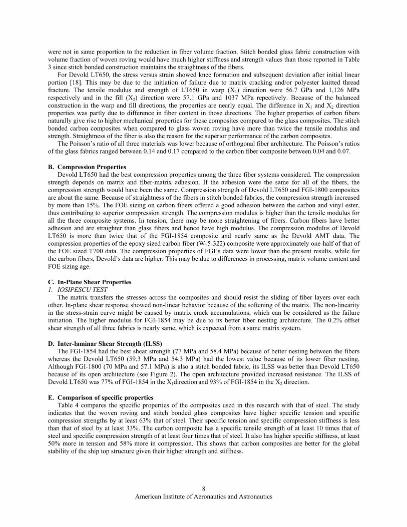
D. Inter Laminar Shear Strength (ILSS) Test Tests were conducted using the modified short beam shear test [15]. The ILSS was calculated from the failure
load. Failure modes of the specimens revealed typical near mid-plane delaminations [18]. The average and standard deviation of ILSS for all the three materials are listed in Table 3. The coefficient of variation of the test data is less than 4%.
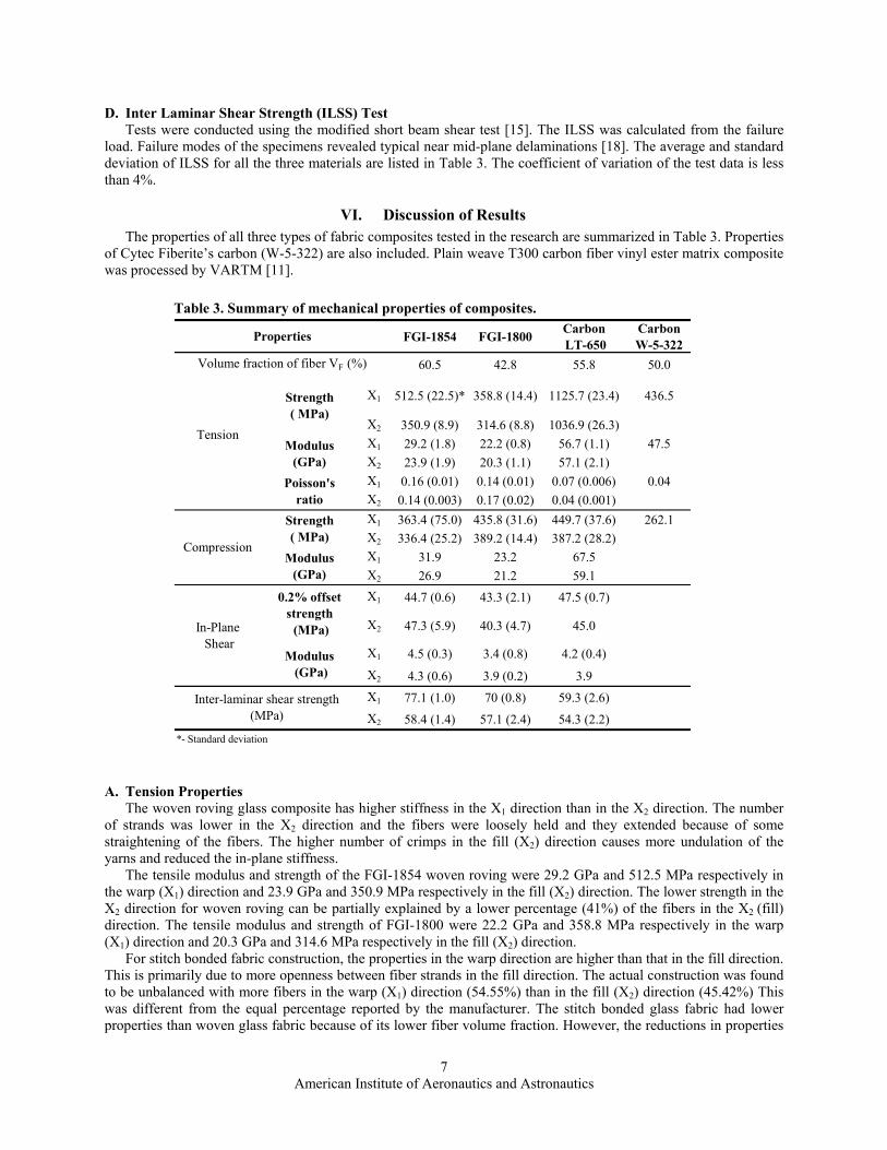
VI. Discussion of Results The properties of all three types of fabric composites tested in the research are summarized in Table 3. Properties
of Cytec Fiberite’s carbon (W-5-322) are also included. Plain weave T300 carbon fiber vinyl ester matrix composite was processed by VARTM [11].
A. Tension Properties The woven roving glass composite has higher stiffness in the X1 direction than in the X2 direction. The number
of strands was lower in the X2 direction and the fibers were loosely held and they extended because of some straightening of the fibers. The higher number of crimps in the fill (X2) direction causes more undulation of the yarns and reduced the in-plane stiffness.
The tensile modulus and strength of the FGI-1854 woven roving were 29.2 GPa and 512.5 MPa respectively in the warp (X1) direction and 23.9 GPa and 350.9 MPa respectively in the fill (X2) direction. The lower strength in the X2 direction for woven roving can be partially explained by a lower percentage (41%) of the fibers in the X2 (fill) direction. The tensile modulus and strength of FGI-1800 were 22.2 GPa and 358.8 MPa respectively in the warp (X1) direction and 20.3 GPa and 314.6 MPa respectively in the fill (X2) direction.
For stitch bonded fabric construction, the properties in the warp direction are higher than that in the fill direction. This is primarily due to more openness between fiber strands in the fill direction. The actual construction was found to be unbalanced with more fibers in the warp (X1) direction (54.55%) than in the fill (X2) direction (45.42%) This was different from the equal percentage reported by the manufacturer. The stitch bonded glass fabric had lower properties than woven glass fabric because of its lower fiber volume fraction. However, the reductions in properties
Table 3. Summary of mechanical properties of composites.
FGI-1854 FGI-1800 CarbonLT-650
CarbonW-5-322
60.5 42.8 55.8 50.0
X1 512.5 (22.5)* 358.8 (14.4) 1125.7 (23.4) 436.5
X2 350.9 (8.9) 314.6 (8.8) 1036.9 (26.3)X1 29.2 (1.8) 22.2 (0.8) 56.7 (1.1) 47.5X2 23.9 (1.9) 20.3 (1.1) 57.1 (2.1)X1 0.16 (0.01) 0.14 (0.01) 0.07 (0.006) 0.04X2 0.14 (0.003) 0.17 (0.02) 0.04 (0.001)X1 363.4 (75.0) 435.8 (31.6) 449.7 (37.6) 262.1X2 336.4 (25.2) 389.2 (14.4) 387.2 (28.2)X1 31.9 23.2 67.5X2 26.9 21.2 59.1X1 44.7 (0.6) 43.3 (2.1) 47.5 (0.7)
X2 47.3 (5.9) 40.3 (4.7) 45.0
X1 4.5 (0.3) 3.4 (0.8) 4.2 (0.4)X2 4.3 (0.6) 3.9 (0.2) 3.9X1 77.1 (1.0) 70 (0.8) 59.3 (2.6)X2 58.4 (1.4) 57.1 (2.4) 54.3 (2.2)
*- Standard deviation
In-Plane Shear
Volume fraction of fiber VF (%)
Properties
Poisson'sratio
Strength( MPa)
Modulus(GPa)
Tension
Compression
Strength( MPa)
Modulus(GPa)
Inter-laminar shear strength (MPa)
0.2% offsetstrength (MPa)
Modulus (GPa)
American Institute of Aeronautics and Astronautics
8
were not in same proportion to the reduction in fiber volume fraction. Stitch bonded glass fabric construction with volume fraction of woven roving would have much higher stiffness and strength values than those reported in Table 3 since stitch bonded construction maintains the straightness of the fibers.
For Devold LT650, the stress versus strain showed knee formation and subsequent deviation after initial linear portion [18]. This may be due to the initiation of failure due to matrix cracking and/or polyester knitted thread fracture. The tensile modulus and strength of LT650 in warp (X1) direction were 56.7 GPa and 1,126 MPa respectively and in the fill (X2) direction were 57.1 GPa and 1037 MPa repectively. Because of the balanced construction in the warp and fill directions, the properties are nearly equal. The difference in X1 and X2 direction properties was partly due to difference in fiber content in those directions. The higher properties of carbon fibers naturally give rise to higher mechanical properties for these composites compared to the glass composites. The stitch bonded carbon composites when compared to glass woven roving have more than twice the tensile modulus and strength. Straightness of the fiber is also the reason for the superior performance of the carbon composites.
The Poisson’s ratio of all three materials was lower because of orthogonal fiber architecture. The Poisson’s ratios of the glass fabrics ranged between 0.14 and 0.17 compared to the carbon fiber composite between 0.04 and 0.07.
B. Compression Properties Devold LT650 had the best compression properties among the three fiber systems considered. The compression
strength depends on matrix and fiber-matrix adhesion. If the adhesion were the same for all of the fibers, the compression strength would have been the same. Compression strength of Devold LT650 and FGI-1800 composites are about the same. Because of straightness of the fibers in stitch bonded fabrics, the compression strength increased by more than 15%. The FOE sizing on carbon fibers offered a good adhesion between the carbon and vinyl ester, thus contributing to superior compression strength. The compression modulus is higher than the tensile modulus for all the three composite systems. In tension, there may be more straightening of fibers. Carbon fibers have better adhesion and are straighter than glass fibers and hence have high modulus. The compression modulus of Devold LT650 is more than twice that of the FGI-1854 composite and nearly same as the Devold AMT data. The compression properties of the epoxy sized carbon fiber (W-5-322) composite were approximately one-half of that of the FOE sized T700 data. The compression properties of FGI’s data were lower than the present results, while for the carbon fibers, Devold’s data are higher. This may be due to differences in processing, matrix volume content and FOE sizing age.
C. In-Plane Shear Properties 1. IOSIPESCU TEST
The matrix transfers the stresses across the composites and should resist the sliding of fiber layers over each other. In-plane shear response showed non-linear behavior because of the softening of the matrix. The non-linearity in the stress-strain curve might be caused by matrix crack accumulations, which can be considered as the failure initiation. The higher modulus for FGI-1854 may be due to its better fiber nesting architecture. The 0.2% offset shear strength of all three fabrics is nearly same, which is expected from a same matrix system.
D. Inter-laminar Shear Strength (ILSS) The FGI-1854 had the best shear strength (77 MPa and 58.4 MPa) because of better nesting between the fibers
whereas the Devold LT650 (59.3 MPa and 54.3 MPa) had the lowest value because of its lower fiber nesting. Although FGI-1800 (70 MPa and 57.1 MPa) is also a stitch bonded fabric, its ILSS was better than Devold LT650 because of its open architecture (see Figure 2). The open architecture provided increased resistance. The ILSS of Devold LT650 was 77% of FGI-1854 in the X1direction and 93% of FGI-1854 in the X2 direction.
E. Comparison of specific properties Table 4 compares the specific properties of the composites used in this research with that of steel. The study
indicates that the woven roving and stitch bonded glass composites have higher specific tension and specific compression strengths by at least 63% that of steel. Their specific tension and specific compression stiffness is less than that of steel by at least 33%. The carbon composite has a specific tensile strength of at least 10 times that of steel and specific compression strength of at least four times that of steel. It also has higher specific stiffness, at least 50% more in tension and 58% more in compression. This shows that carbon composites are better for the global stability of the ship top structure given their higher strength and stiffness.

American Institute of Aeronautics and Astronautics
9
VII. Conclusions The VARTM process was used to fabricate glass and carbon fiber composites with woven roving and stitch
bonded fabric E-Glass fiber architectures with Dow Chemical’s Derakane 510A-40 vinyl ester resin. Test panels were of superior quality with low void and no dry fibers and high fiber content. Volume fraction achieved was 58% for woven roving glass and stitch bonded carbon fiber composites. Because of openness of the fiber construction in Knitmat glass fabric (FGI’s 1800-S2), the volume fraction achieved was only 43%. Stitch bonded T700 carbon fiber with FOE sizing produced composites of superior properties, when compared to glass fibers.
Compared to FGI’s woven roving (FGI-1854) composites, the carbon fiber composites had more than twice the tensile modulus and strength, and compression modulus, about 15% higher compression strength, almost similar in-plane shear strength, about 95% of the in-plane shear modulus and inter-laminar shear strength. Devold LT650 properties were better than Cytec Fiberite supplied W-5-322 carbon fiber composites. Straightness of the fiber and FOE sizing were the possible reasons for superior performance of carbon composites. Fiber dominated properties of FGI 1800 stitch bonded fiber composites were lower because of low fiber volume fraction. The matrix dominated properties remained nearly same as that of woven roving FGI 1854 composites. Compression strength of FGI 1800 was 16-20% larger than the FGI 1854 due to the straightness of the stitch bonded fibers. Carbon composites had higher strength and modulus than that of steel. Glass composites had higher strength but lower modulus than steel. Glass composites appear ideal for constructing ship hulls whereas carbon composites could be used for both top and hull structures to reduce the total weight.
Acknowledgements The authors wish to thank the Offices of Naval Research for financial support through grant N 00014-01-1-1033
and Dr. Yapa Rajapakse, Program Manager for ship structures. The authors also wish to thank Fiber Glass Industries (FGI) and Devold AMT AS for materials and cooperation.
References 1Dow, Marvin B. and Benson Dexter, H., “Development of Stitched, Braided and Woven Composite Structures,” NASA/TP-
97-206234, 1997 2Emehel, T.C. and Shivakumar, K.N., “Tow Collapse Model for Compression Strength of Textile Composites,” Jl.
Reinforced Plastics and Composites, Vol. 16, No. 1, 1997, pp. 86-101. 3Cox, Brian., “Failure Models for Textile Composites”, NASA Contractor Report 4686, Contract NAS1-19243. 4Daniel, Isaac M. and Shah, Ori., “Engineering Mechanics of Composite Materials,” Oxford University, New York, 1994,
Chap. 1. 5 Karl Mayer Textile Machine Corp. (ed.), Directionally Oriented Structures, Germany, 1999. 6Copcentra MAX 3 CNC- Examination of non-crimp reinforcement for composites [online database], URL:
http://www.liba.de/tricot/cop_max_examination.htm [cited 03 April 2004]. 7Data sheet for Rovcloth 1854 [online database], URL: http://www.fiberglassindustries.com/rovcloth.htm [cited 02
February 2003]. 8Data sheet for Knitmat 1800 [online database], URL: http://www.fiberglassindustries.com/knitmat.htm [cited 02
February 2003]. 9Product data sheet for LT 650-C12 Biaxial Carbon Product [online database], URL:
http://www.amt.no/files/documents/carbonfibre_reinforcements_overview.pdf [cited 02 February 2003].
Table 4 Comparison of specific properties. FGI
1854FGI1800
Carbon LT-650 Steel
X1 259 196 717X2 177 172 660X1 15 12 36X2 12 11 36X1 184 238 286X2 170 213 247X1 16 13 43X2 14 12 38
64
24
64
24
Properties
Compression
Strength( MPa/g/cc)
Modulus(GPa/g/cc)
Tension Strength
( MPa/g/cc)Modulus
(GPa/g/cc)
American Institute of Aeronautics and Astronautics
10
10Product information for Derakane 510A-40 [online database], URL: http://www.dow.com/derakane/prod/d-510a-40/ [cited 02 February 2003].
11Smith, S., Emmanwori, L., Sadler, R. and Shivakumar, K., “Evaluation of Composite Sandwich Panels Fabricated Using Vacuum Assisted Resin Transfer Molding,” SAMPE, Long Beach, CA, May 2000.
12Sadler, R., Sharpe, M., Swaminathan, G., and Shivakumar, K., “Mechanical Properties of Panels Fabricated by the VARTM Processed Composites Using Different Fibers and Fabric Architectures,” 18th Annual Technical Conference of ASC, University of Florida, Gainesville, FL, Oct. 2003.
13Hsu, K., Bernard, J., Peters, J., Dayal, V., “Physical basis of tap test as a quantitative imaging tool for composite structures on aircraft,” Prog. Quantitative NDE, edited by D. O. Thompson and D. E. Chimenti, Vol. 19, Amer. Inst. Phys., Melville, New York, 2000. pp 2053-2060.
14Annual Book of ASTM Standards, Vol. 15.3, ASTM International, West Conshohocken, PA. 2002, p.126 15Abali, F., Pora, A. and Shivakumar, K., “Modified Short Beam Shear Test For Measurement of ILSS of Carbon-Carbon
Composites,” Jl. of Composite Materials, Vol. 37, No. 5, 2003, pp.453-464. 16Budiansky, B., “Micromechanics,” Computers and Structures, Vol. 16, No.1, 1983. 17Fleck, N. A. and Budiansky, B., “Compressive Failure of Fibre Composites due to Microbuckling,” Proceedings of IUTAM
Symosium. on Inelastic Deformation of Composite Materials, edited by J. Dvorak, Troy, New York, pp. 235-273. 18Swaminathan, G., Shivakumar, K., Sharpe, M., “Mechanical Properties of Glass and T700 Carbon/Vinyl Ester
Composites,” Developments in Theoretical and Applied Mechanics, edited by Hassan Mahfuz and Mahesh Hosur, Vol. 22, SECTAM, Tuskegee University, AL, 2004. pp 227-240.