mechanical design - greetings from eng....
TRANSCRIPT
Mechanical Design
Ben Potsaid
Control System Design
February 26, 2003
Mechanical Design
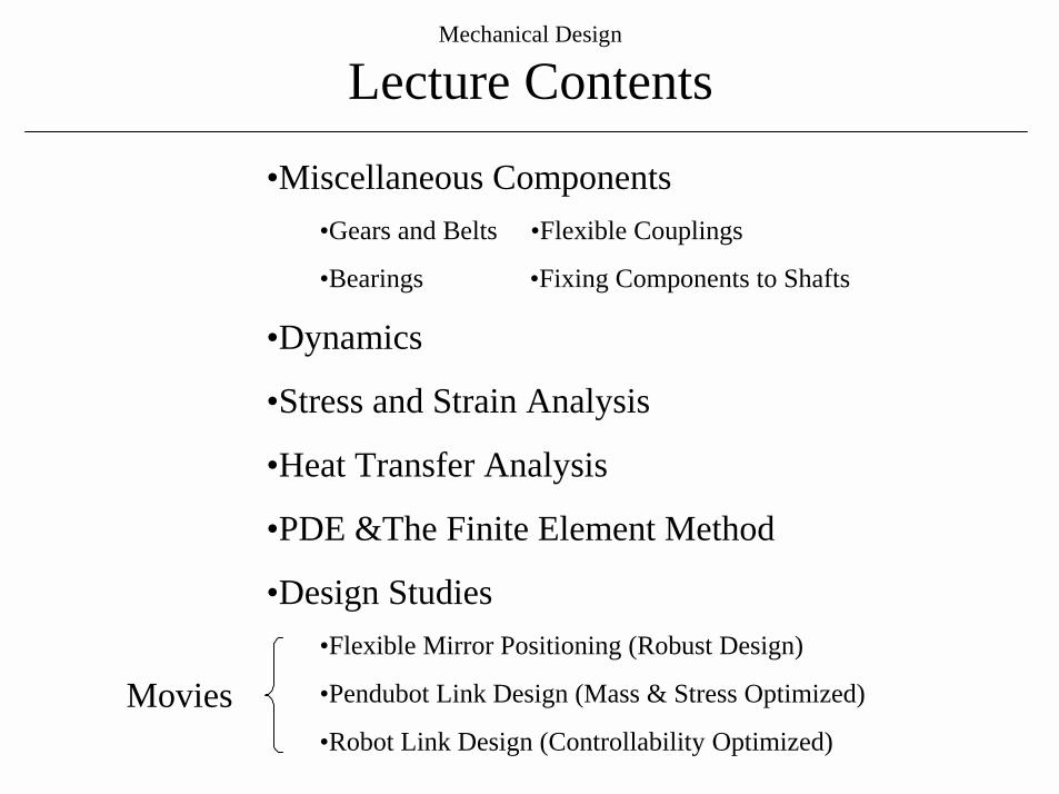
Lecture Contents
•Miscellaneous Components•Gears and Belts •Flexible Couplings
•Bearings •Fixing Components to Shafts
•Dynamics
•Stress and Strain Analysis
•Heat Transfer Analysis
•PDE &The Finite Element Method
•Design Studies•Flexible Mirror Positioning (Robust Design)
•Pendubot Link Design (Mass & Stress Optimized)
•Robot Link Design (Controllability Optimized)Movies
Mechanical Design
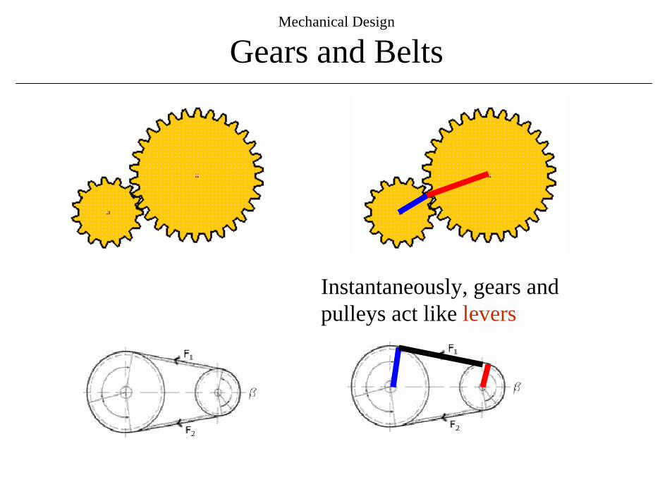
Gears and Belts
Instantaneously, gears and pulleys act like levers
Mechanical Design
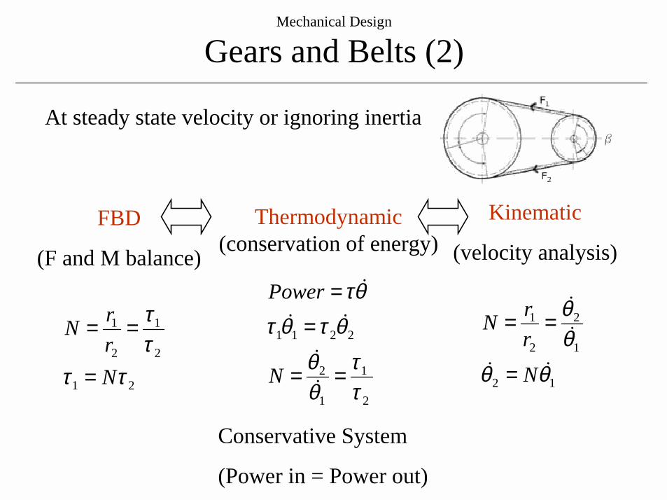
Gears and Belts (2)
Conservative System
(Power in = Power out)
2
1
1
2
2211
ττ
θθ
θτθτθτ
==
=
=
!!!!!
N
Power
21
2
1
2
1
ττττ
NrrN
=
==
Thermodynamic(conservation of energy)
FBD
(F and M balance)
At steady state velocity or ignoring inertia
Kinematic
(velocity analysis)
12
1
2
2
1
θθθθ
!!!!
NrrN
=
==
Mechanical Design
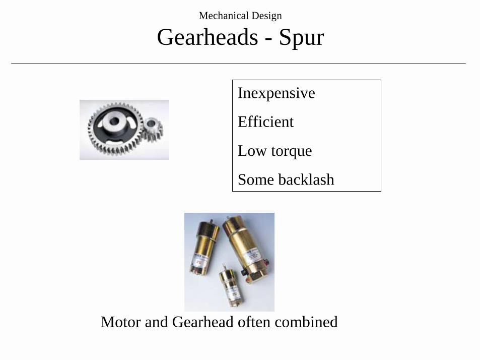
Gearheads - Spur
Inexpensive
Efficient
Low torque
Some backlash
Motor and Gearhead often combined
Mechanical Design
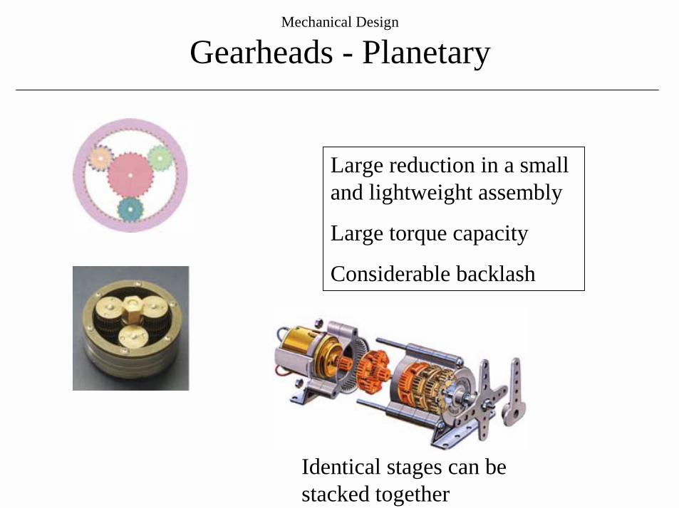
Gearheads - Planetary
Large reduction in a small and lightweight assembly
Large torque capacity
Considerable backlash
Identical stages can be stacked together
Mechanical Design
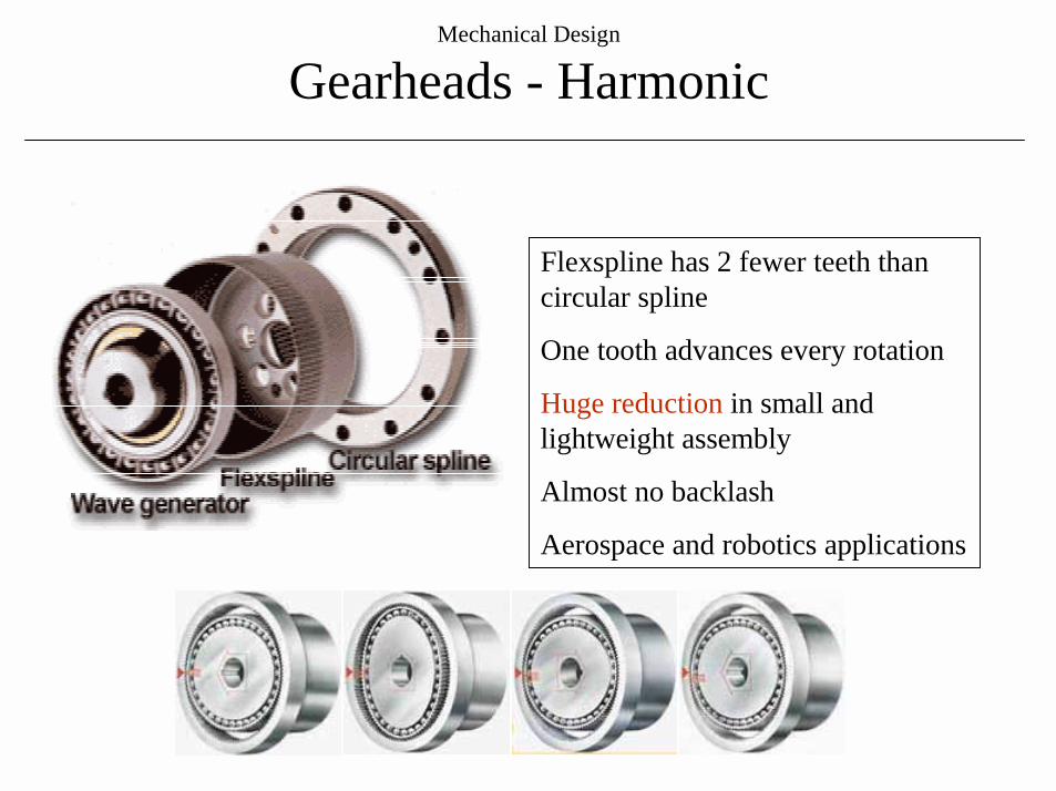
Gearheads - Harmonic
Flexspline has 2 fewer teeth than circular spline
One tooth advances every rotation
Huge reduction in small and lightweight assembly
Almost no backlash
Aerospace and robotics applications
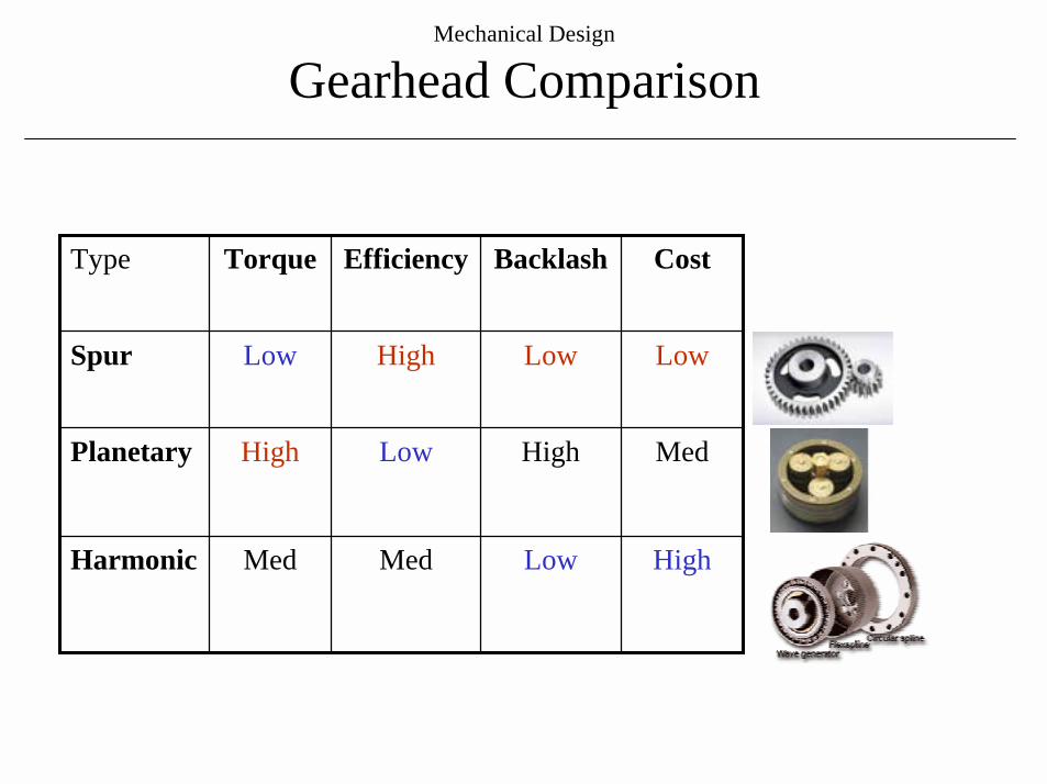
HighLowMedMedHarmonic
MedHighLowHighPlanetary
LowLowHighLowSpur
CostBacklashEfficiencyTorqueType
Mechanical Design
Gearhead Comparison
Mechanical Design
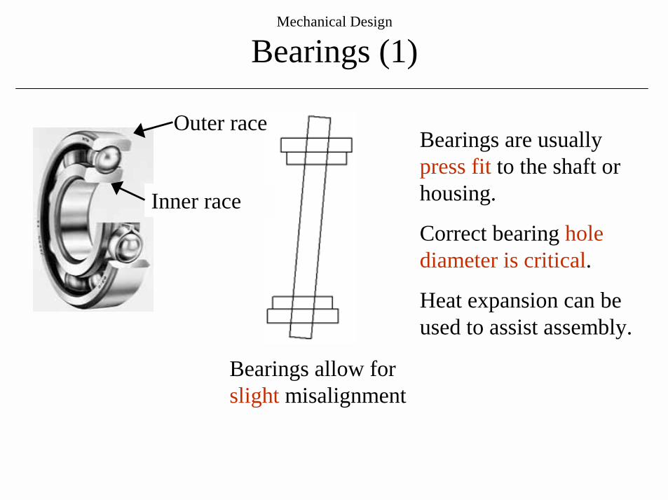
Bearings (1)
Inner race
Outer race
Bearings allow for slight misalignment
Bearings are usually press fit to the shaft or housing.
Correct bearing hole diameter is critical.
Heat expansion can be used to assist assembly.
Mechanical Design
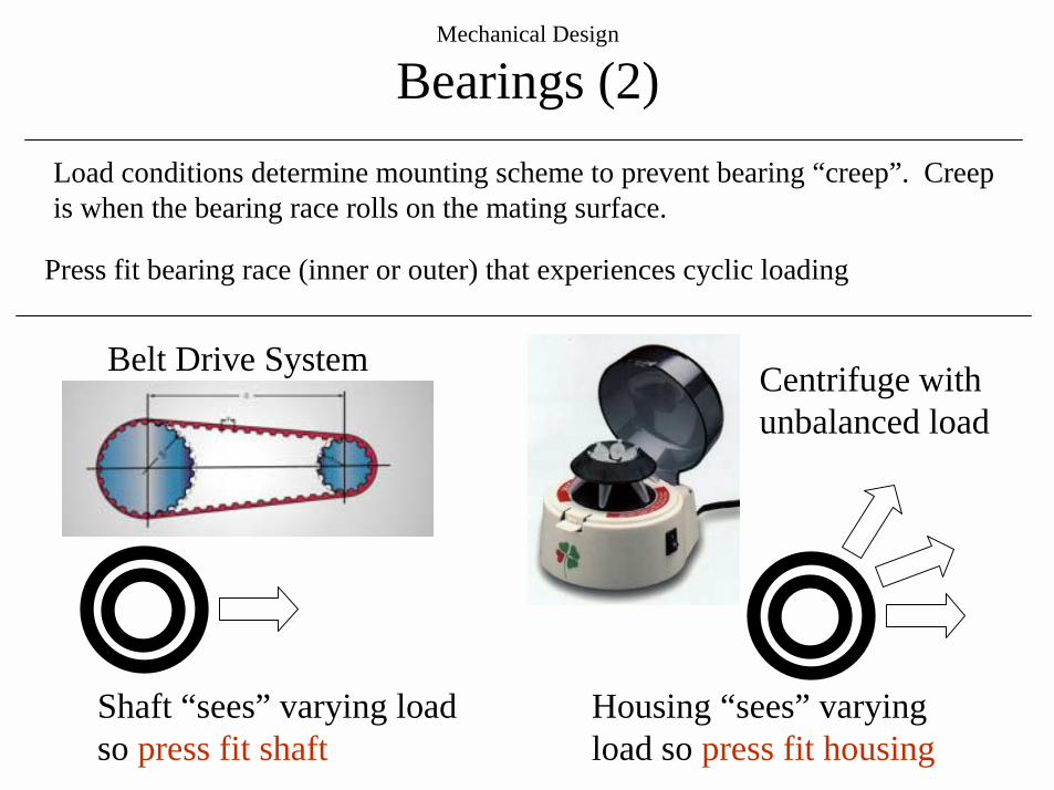
Bearings (2)Load conditions determine mounting scheme to prevent bearing “creep”. Creep is when the bearing race rolls on the mating surface.
Shaft “sees” varying load so press fit shaft
Press fit bearing race (inner or outer) that experiences cyclic loading
Housing “sees” varying load so press fit housing
Belt Drive System Centrifuge with unbalanced load
Mechanical Design
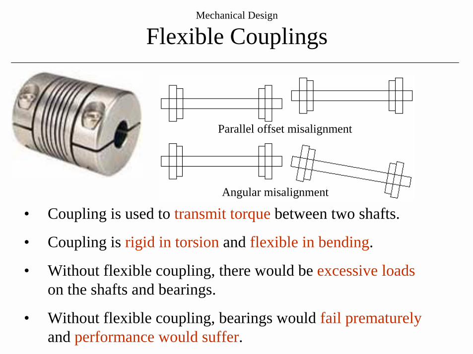
Flexible Couplings
• Coupling is used to transmit torque between two shafts.
• Coupling is rigid in torsion and flexible in bending.
• Without flexible coupling, there would be excessive loadson the shafts and bearings.
• Without flexible coupling, bearings would fail prematurelyand performance would suffer.
Angular misalignment
Parallel offset misalignment
Mechanical Design
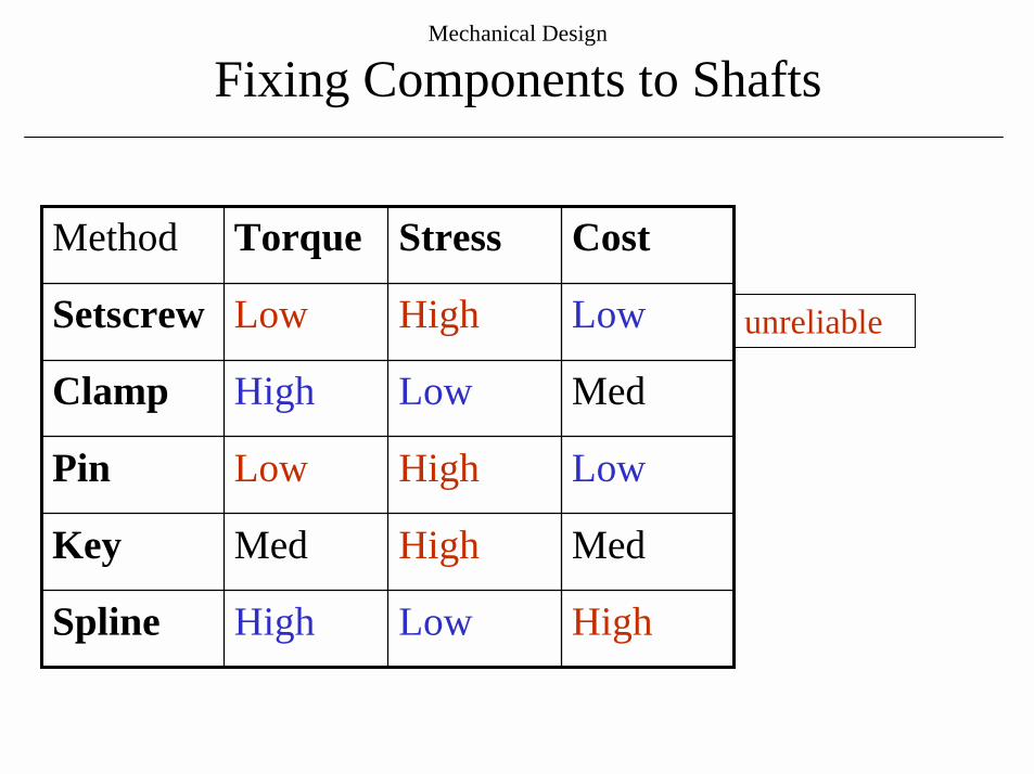
Fixing Components to Shafts
HighLowHighSpline
MedHighMedKey
LowHighLowPin
MedLowHighClamp
LowHighLowSetscrew
CostStressTorqueMethod
unreliable
Mechanical Design
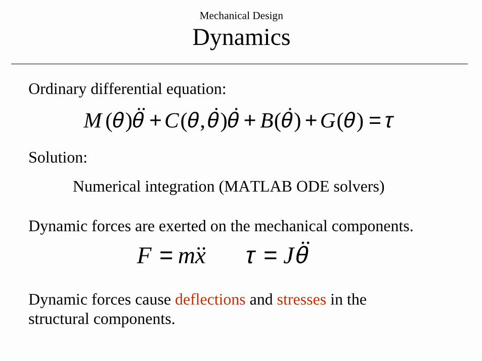
Dynamics
τθθθθθθθ =+++ )()(),()( GBCM !!!!!Ordinary differential equation:
Solution:
Numerical integration (MATLAB ODE solvers)
θτ !!!! JxmF == Dynamic forces are exerted on the mechanical components.
Dynamic forces cause deflections and stresses in the structural components.
Mechanical Design
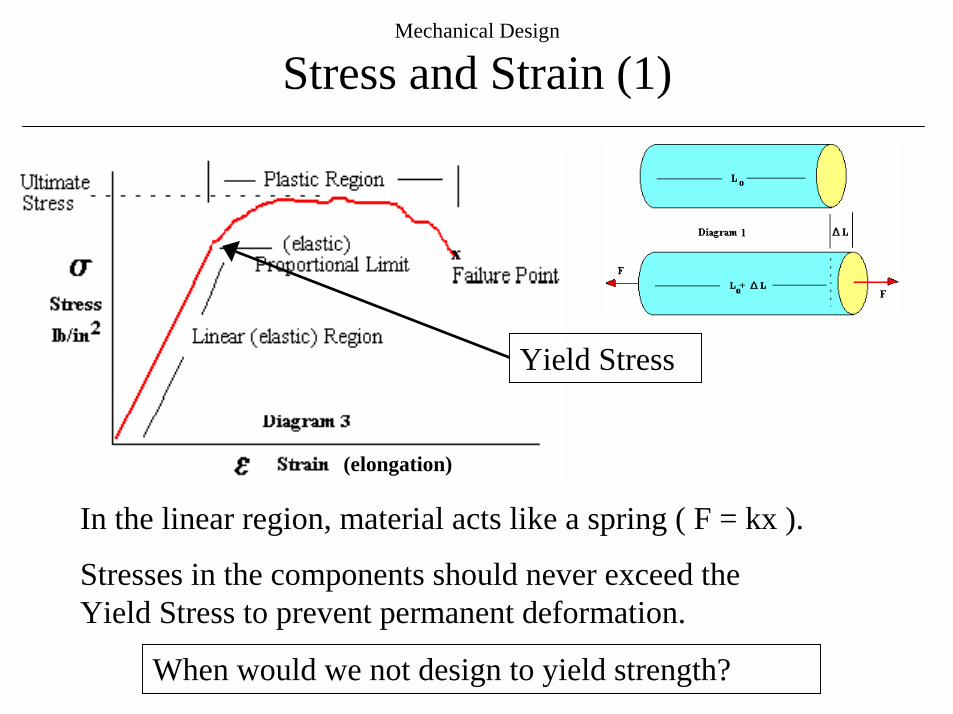
Stress and Strain (1)
When would we not design to yield strength?
Yield Stress
Stresses in the components should never exceed the Yield Stress to prevent permanent deformation.
(elongation)
In the linear region, material acts like a spring ( F = kx ).
Mechanical Design
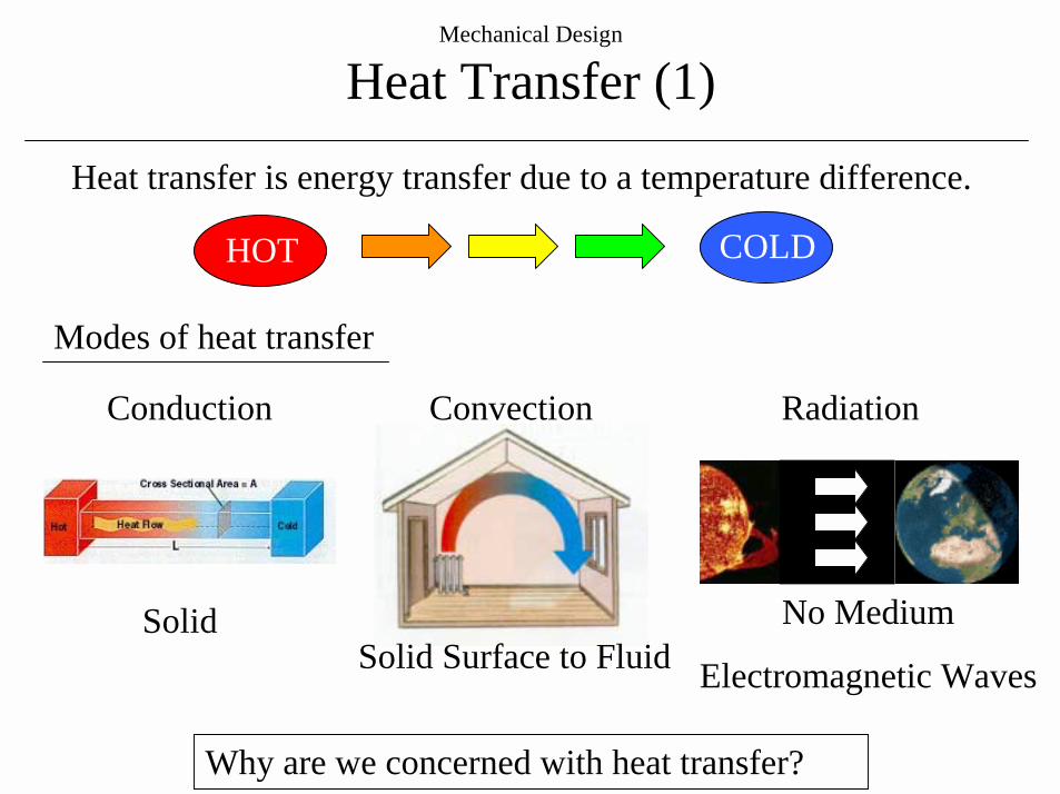
Heat Transfer (1)
Why are we concerned with heat transfer?
Heat transfer is energy transfer due to a temperature difference.
HOT COLD
Modes of heat transfer
Conduction Convection Radiation
SolidSolid Surface to Fluid
No Medium
Electromagnetic Waves
Mechanical Design
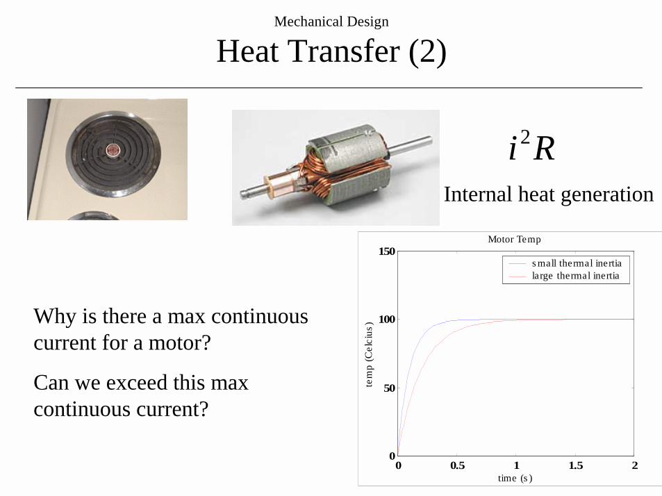
Heat Transfer (2)
Why is there a max continuous current for a motor?
Can we exceed this max continuous current?
Ri2
Internal heat generation
0 0.5 1 1.5 20
50
100
150
time (s )
tem
p (C
elci
us)
Motor Temp
s mall thermal inertialarge thermal inertia
Mechanical Design
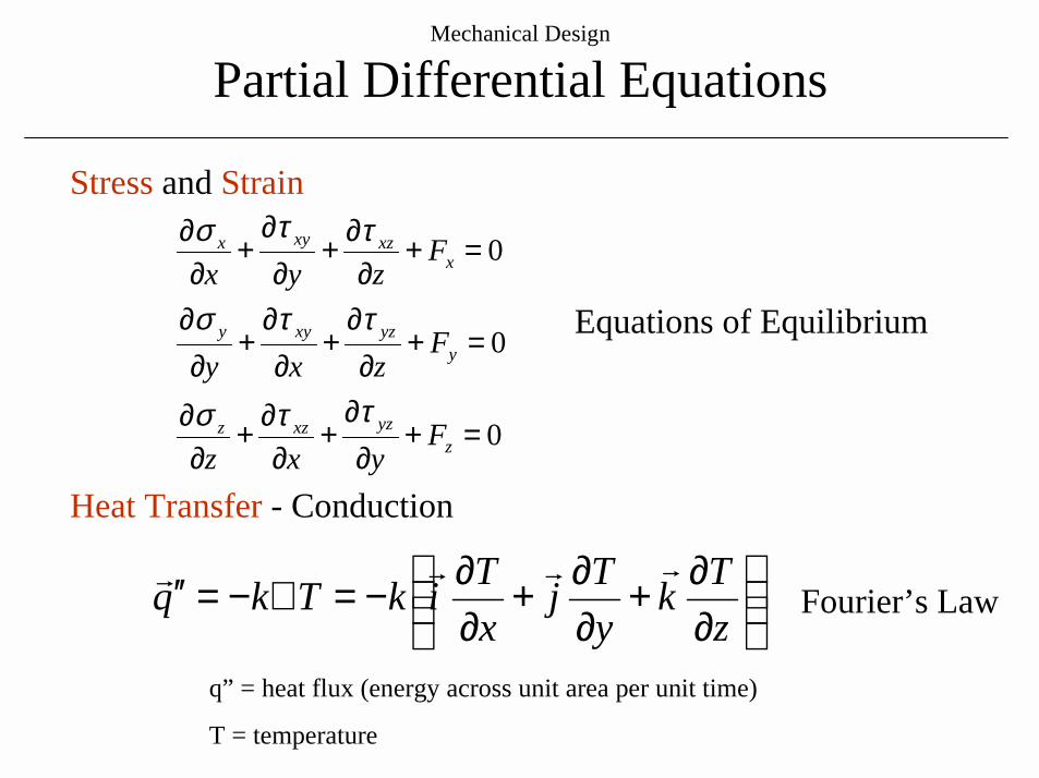
Partial Differential Equations
Heat Transfer - Conduction
q” = heat flux (energy across unit area per unit time)
T = temperature
∂∂+
∂∂+
∂∂−=∇−=′′
zTk
yTj
xTikTkq
""""
Stress and Strain
Fourier’s Law
0
0
0
=+∂
∂+
∂∂+
∂∂
=+∂
∂+
∂∂
+∂
∂
=+∂
∂+∂
∂+
∂∂
zyzxzz
yyzxyy
xxzxyx
Fyxz
Fzxy
Fzyx
ττσ
ττσ
ττσ
Equations of Equilibrium
Mechanical Design
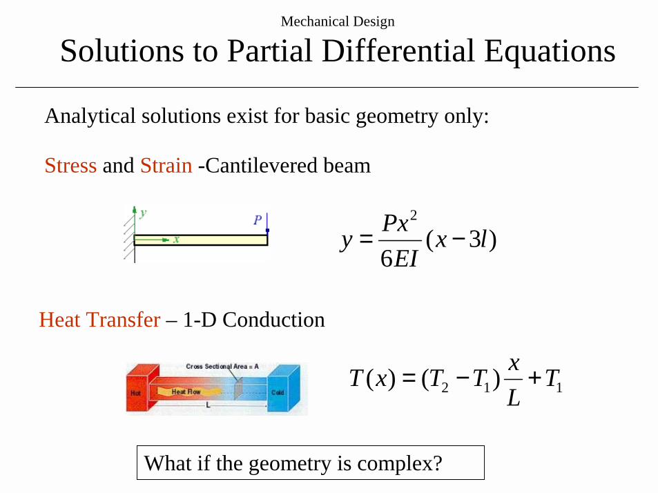
Solutions to Partial Differential Equations
Analytical solutions exist for basic geometry only:
What if the geometry is complex?
Heat Transfer – 1-D Conduction
Stress and Strain -Cantilevered beam
)3(6
2
lxEI
Pxy −=
112 )()( TLxTTxT +−=

Mechanical Design
Finite Element Method
Method to find an approximate solution to PDE by discretization.
• Solution converges as mesh is refined (Galerkin Method).
• Very time consuming.
• Computation time vs. modeling accuracy.
• What resolution mesh is required?
Stress in piston
Hook Stress
Mechanical Design
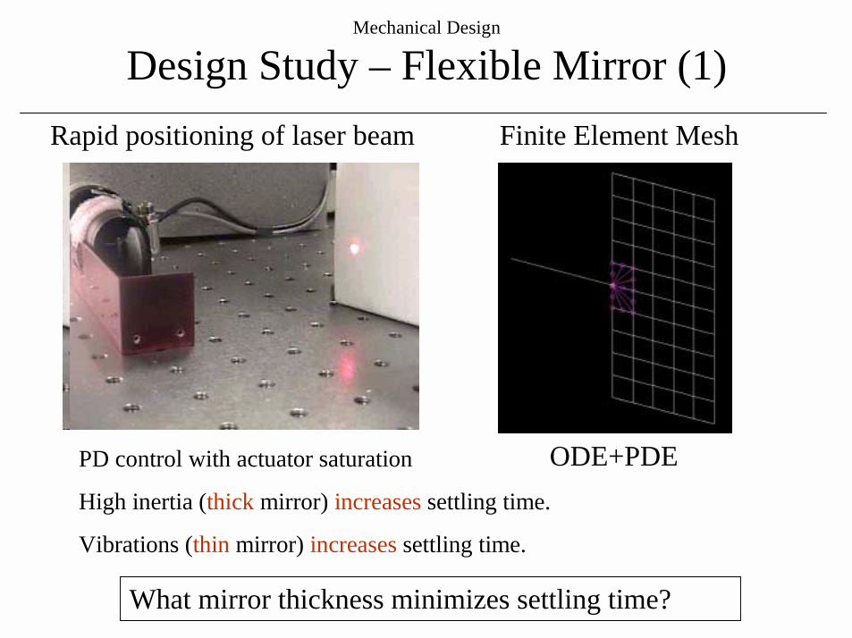
Design Study – Flexible Mirror (1)Finite Element MeshRapid positioning of laser beam
PD control with actuator saturation
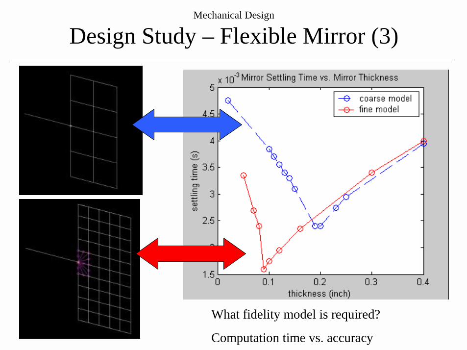
High inertia (thick mirror) increases settling time.
Vibrations (thin mirror) increases settling time.
What mirror thickness minimizes settling time?
ODE+PDE
Mechanical Design
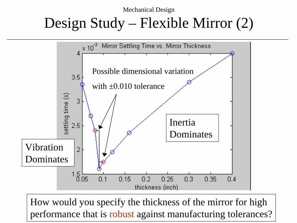
Design Study – Flexible Mirror (2)
Possible dimensional variation
with ±0.010 tolerance
How would you specify the thickness of the mirror for high performance that is robust against manufacturing tolerances?
Vibration Dominates
Inertia Dominates
Mechanical Design
Design Study – Flexible Mirror (3)
What fidelity model is required?
Computation time vs. accuracy
Mechanical Design
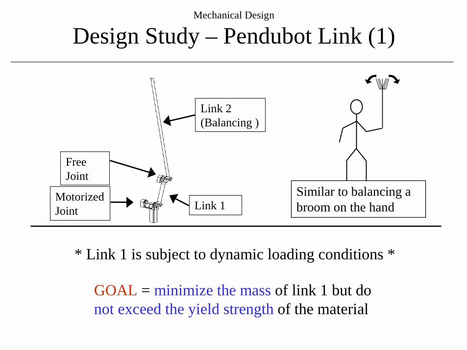
Design Study – Pendubot Link (1)
Motorized Joint
Free Joint
Link 2 (Balancing )
Link 1Similar to balancing a broom on the hand
* Link 1 is subject to dynamic loading conditions *
GOAL = minimize the mass of link 1 but donot exceed the yield strength of the material

Mechanical Design
Design Study – Pendubot Link (2)
* Lower Link is subject to dynamic loads *
Pendubot Balancing
Mechanical Design
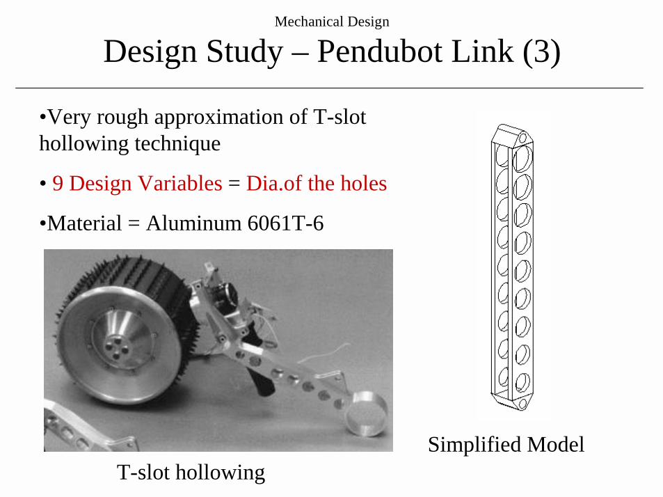
Design Study – Pendubot Link (3)
•Very rough approximation of T-slot hollowing technique
• 9 Design Variables = Dia.of the holes
•Material = Aluminum 6061T-6
Simplified ModelT-slot hollowing
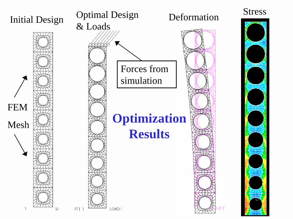
StressDeformationOptimal Design & Loads
Initial Design
OptimizationResults
Forces from simulation
FEM
Mesh
Mechanical Design
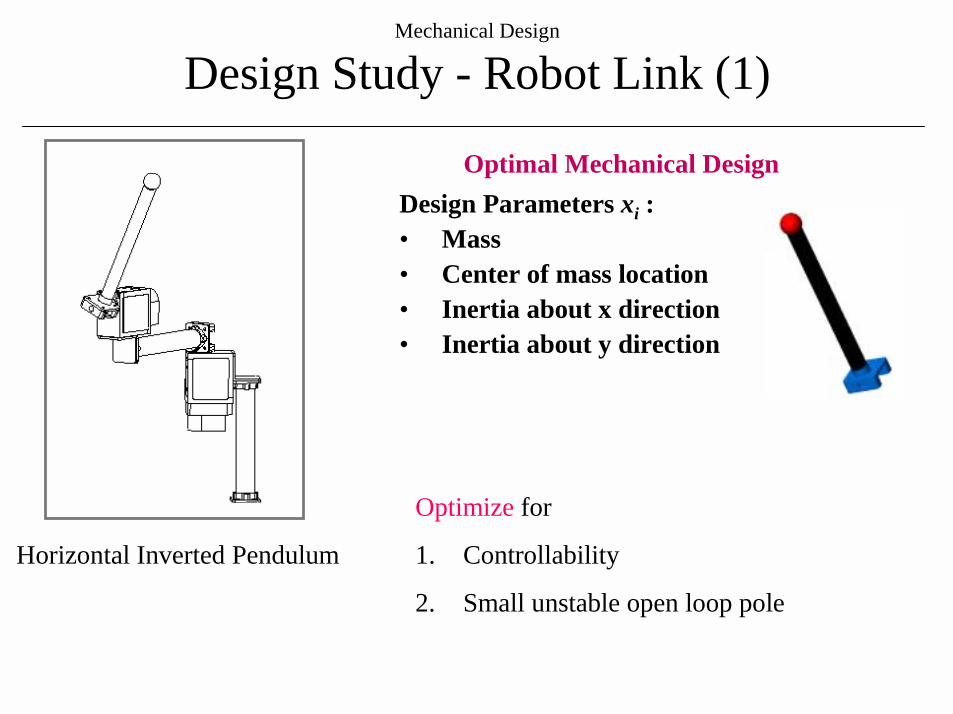
Design Study - Robot Link (1)
Horizontal Inverted Pendulum
Design Parameters xi :• Mass • Center of mass location• Inertia about x direction• Inertia about y direction
Optimal Mechanical Design
Optimize for
1. Controllability
2. Small unstable open loop pole
Mechanical Design
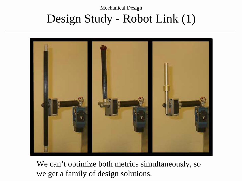
Design Study - Robot Link (1)
We can’t optimize both metrics simultaneously, so we get a family of design solutions.
Mechanical Design
Design Study - Robot Link (2)
Mechanical Design
Conclusion
• Mechanical Design and Control System Design cannot be done separately when high performance is required.
• Use the latest technologies and design tools to your advantage.
• Don’t forget about first principles and the basics.