measurement of photovoltaic cell parameters - imiue.polsl.pl · 1.1.solar radiation //...
TRANSCRIPT
Measurement of photovoltaic cell parameters // Badanie ogniw fotowoltaicznych
1
Division of Metrology and Power Processes Automation
Faculty of Energy and Environmental Engineering
Institute of Power Engineering and Turbomachinery
Wydział Inżynierii Środowiska i Energetyki
Instytut Maszyn i Urządzeń Energetycznych
Measurement of photovoltaic cell parameters
Badanie ogniw fotowoltaicznych
Laboratory of Distributed Energy and Renewable Energy Sources
Laboratorium Energetyki Rozproszonej i Odnawialnych Źródeł Energii
(R-1)
Developed by PhD Daniel Węcel
Opracował: dr inż. Daniel Węcel
www.imiue.polsl.pl/~wwwzmiape

Measurement of photovoltaic cell parameters // Badanie ogniw fotowoltaicznych
2
AIM OF THE EXERCISE // CEL ĆWICZENIA
The aim of the exercise is to determine the basic operating characteristics of photovoltaic cell
(module), its parameters and to examine the dependence of the module’s power on the
inclination angle relative to the light source.
// Celem ćwiczenia jest wyznaczenie podstawowych charakterystyk pracy, parametrów ogniwa
(modułu) fotowoltaicznego oraz zbadanie zależności mocy modułu od kąta nachylenia
względem źródła światła.
Table of symbols and abbreviations // Spis oznaczeń i skrótów
Ev Illuminance // natężenie oświetlenia lux
G Solar irradiance // natężenie promieniowania słonecznego W/m2
Gsc Solar constant // stała słoneczna W/m2
Gd Diffuse irradiance on a fixed plane // promieniowanie rozporoszone
padające na powierzchnię W/m2
G0 Solar irradiance on a photovoltaic cell array // natężenie
promieniowania słonecznego na powierzchni ogniwa
fotowoltaicznego
W/m2
H Solar irradiation, insolation // nasłonecznienie (napromieniowanie)
słoneczne
kWh/m2 (per day,
month, year)
h Planck's constant // stała Plancka (4.135667662·10-15 eV·s) eV·s
IMPP Current at the maximum power point // natężenie prądu w punkcie
mocy maksymalnej A
ISC Short circuit current // natężenie prądu zwarcia A
Pmax Maximum power // moc maksymalna Wp (Wpeak)
tPV Temperature of photovoltaic cell // temperatura ogniwa
fotowoltaicznego °C
tamb Ambient temperature // temperatura otoczenia °C
UMPP Voltage at the maximum power point // napięcie w punkcie mocy
maksymalnej V
UOC Open-circuit voltage // napięcie obwodu otwartego V
α temperature coefficient of the short-circuit current //
współczynnik temperaturowy natężenia prądu %ISC/°C
β temperature coefficient of the open-circuit voltage //
współczynnik temperaturowy napięcia %UOC/°C
γ temperature coefficient of the power // współczynnik
temperaturowy mocy %Pmax/°C
λ wavelength // długość fali nm
AM Air Mass // współczynnik optycznej masy powietrza -
DNI Direct normal irradiance // natężenie promieniowania bezpośredniego W/m2
FF Fill Factor // współczynnik wypełnienia -
MPP Maximum power point // punkt mocy maksymalnej
STC Standard Test Condition // warunki standardowe badania

Measurement of photovoltaic cell parameters // Badanie ogniw fotowoltaicznych
3
1. INTRODUCTION// WSTĘP
1.1. Solar radiation // Promieniowanie słoneczne
Solar radiation - the electromagnetic radiation and elementary particles (photons) given off by
the Sun. The energy of photons E is related to the wavelength of the Planck-Einstein relation:
// Promieniowanie słoneczne – strumień fal elektromagnetycznych i cząstek elementarnych
(fotonów) wydzielanych przez Słońce. Energia fotonów E jest powiązana z długością fali
zależnością Plancka-Einsteina:
𝐸 =ℎ ∙ 𝑐
𝜆= ℎ ∙ 𝑓
h = 4.135667662·10-15 eV·s – Planck's constant, c – speed of light, λ – wavelenght, f –
frequency // h – stała Plancka , c – prędkość światła, λ – długość fali, f - częstotliwość
The solar irradiance reaching the upper limits of the atmosphere is determined by the solar
constant GSC. This value is defined for the mean Earth-Sun distance and is about 1366.1 W/m2.
The solar irradiance changes in the annual cycle, due to changes in the distance between Earth
and the Sun (January 3, 1.47 × 10⁸ km, July 4, 1.52 × 10⁸ km), in the range of ± 3.4% (1420
and 1325 W/m2, respectively).
// Natężenie promieniowania słonecznego docierającego do górnych granic atmosfery
określone jest przez stałą słoneczną GSC. Wielkość ta jest zdefiniowana dla średniej odległości
Ziemia-Słońce i wynosi około 1366.1 W/m2. Natężenie promieniowania słonecznego zmienia
się w cyklu rocznym, ze względu na zmiany odległości pomiędzy Ziemią a Słońcem (3 stycznia
1.47×10⁸ km, 4 lipca 1.52×10⁸ km), w zakresie ±3,4% (odpowiednio 1420 i 1325 W/m2).
The spectrum of solar radiation over the upper limits of the atmosphere is similar to the radiation
of a black body with a temperature of about 5800 K described by the Planck distribution. Due
to reflection, dispersion and absorption the part of radiation by gases, the spectrum of radiation
reaching the Earth's surface is changed as shown in Figure 1.
// Widmo promieniowania słonecznego ponad górnymi warstwami atmosfery jest zbliżone do
promieniowania ciała doskonale czarnego o temperaturze około 5800 K opisywanego
rozkładem Plancka. Ze względu na odbijanie, rozpraszanie i pochłanianie części
promieniowania przez gazy, widmo promieniowania docierającego do powierzchni Ziemi jest
zmienione co przedstawiono na rys. 1.

Measurement of photovoltaic cell parameters // Badanie ogniw fotowoltaicznych
4
The following ranges are distinguished in the solar spectrum // W spektrum promieniowania
słonecznego wyróżniamy następujące zakresy
Table 1
Pasmo
Wavelenght
// Długość
fali, nm
Solar irradiance in
the range // Energia
promieniowania
słonecznego, W/m2
The share of energy in total
solar radiation // Udział
energii w całkowitym
promieniowaniu słonecznym
Ultraviolet (UV) //
Ultrafiolet <350 62 4.5%
Near ultraviolet //
Bliski ultrafiolet 350 – 400 57 4.2%
Visible // Widzialne 400 – 700 522 38.2%
Near infrared //
Bliska podczerwień 700 – 1000 309 22.6%
Infrared //
Podczerwień >1000 417 30.5%
Solar constant //
Stała słoneczna 1366,1
Fig. 1 The spectrum of solar radiation.
//Rys.1 Widmo promieniowania słonecznego

Measurement of photovoltaic cell parameters // Badanie ogniw fotowoltaicznych
5
Air Mass coefficient - The weakening of the solar radiation depends on the way that solar rays
travel through the atmosphere. Specifies them Air Mass coefficient AM. It is the ratio of the
mass of the atmosphere through which the radiation passes, to the mass of the atmosphere
through which the radiation passes, when the Sun is at its zenith. It defines also the direct optical
path length L through the Earth's atmosphere, expressed as a ratio relative to the atmosphere
thickness D.
// Współczynnik optycznej masy powietrza - Osłabienie natężenia promieniowania zależy od
drogi, którą przebywa ono w atmosferze. Określa je liczba masy powietrza AM (ang. Air Mass;
współczynnik optycznej masy powietrza). Jest to stosunek masy atmosfery przez którą
przechodzi promieniowanie, do masy atmosfery przez którą przechodzi promieniowanie, gdy
Słońce jest w zenicie. Definiowane jest również jako stosunek długości drogi L pokonywanej
przez wiązkę optyczna bezpośredniego promieniowania słonecznego przechodzącego przez
atmosferę do jej grubości D.
𝐴𝑀 =𝐿
𝐷≈
1
sin𝜓
Fig. 2. The method of determining the air mass coefficient.
//Rys.2 Sposób określania współczynnika optycznej masy powietrza
Spectral distribution of reference solar radiation is determined at AM = 1.5. The value of the
reference global solar irradiance on surface of the Earth is GSTC = 1000 W/m2.

Measurement of photovoltaic cell parameters // Badanie ogniw fotowoltaicznych
6
// Rozkład widmowy wzorcowego natężenia promieniowania słonecznego jest określany przy
AM=1,5. Wartość wzorcowego natężenia promieniowania całkowitego na powierzchni Ziemi
wynosi GSTC = 1000 W/m2.
1.2. Photovoltaic cell // Ogniwo fotowoltaiczne
A photovoltaic cell (or solar cell) is a semiconductor element with a p-n junction in which
a photovoltaic phenomenon occurs. As a result of the absorption of solar energy in the area of
the p-n junction, part of the valence electrons from the atoms in the crystal lattice of the
semiconductor is extracted from its place, that is the generation a pair of electron-hole carriers
(hole means no electron).
The electric field occurring in the area of the p-n junction causes the separation of carriers in
the semiconductor (electrons are transported into n-type semiconductor, holes into p-type
semiconductor) and the appearance voltage at the terminals of the cell. Connecting the load to
the cell electrodes and closing the electric circuit will cause electrons flow. The resulting current
is proportional to the solar irradiance and the surface of the photovoltaic cell. Whereas the
voltage depends on the load.
// Ogniwo fotowoltaiczne (inaczej fotoogniwo) jest elementem półprzewodnikowym ze złączem
p-n, w którym zachodzi zjawisko fotowoltaiczne. W wyniku absorpcji energii promieniowania
słonecznego w obszarze złącza p-n część elektronów walencyjnych z atomów w sieci
krystalicznej półprzewodnika zostaje wybita ze swojego miejsca, czyli następuje tzw. generacja
pary nośników elektron-dziura (dziura oznacza brak elektronu).
Występujące w obszarze złącza pole elektryczne powoduje rozdzielenie nośników w
półprzewodniku (elektrony są transportowane w jednym kierunku, dziury w przeciwnym) i
pojawienie się napięcia na zaciskach ogniwa. Przyłączenie odbiornika do ogniwa i zamknięcie
obwodu elektrycznego spowoduje przepływ elektronów. Powstające natężenie prądu jest
proporcjonalne do natężenia promieniowania słonecznego i powierzchni ogniwa
fotowoltaicznego. Natomiast napięcie jest zależne od obciążenia.

Measurement of photovoltaic cell parameters // Badanie ogniw fotowoltaicznych
7
Fig. 3. The principle of operation of the photovoltaic cell
//Rys.3 Zasada działania ogniwa fotowoltaicznego
The photovoltaic cells are usually made of silicon (monocrystalline, polycrystalline or
amorphous), semiconductors from 13 and 15 group, e.g. Ga (gal), As (arsenic) or in the form
of thin layers, e.g. CdTe (cadmium telluride) or CIGS (copper, indium, gal, selenium). More
and more often are also available the organic photovoltaic cells, which are currently
characterized by low efficiency, but also very low production costs.
Many photovoltaic cells connected together are called a solar panel or module (or shorter: a PV
module).
// Ogniwa najczęściej wykonuje się z krzemu (monokrystalicznego, polikrystalicznego lub
amorficznego), półprzewodników z grupy 13 i 15 np. Ga (gal), As (arsen) bądź w postaci
cienkich warstw np. CdTe (tellurku kadmu) lub CIGS (miedź, ind, gal, selen). Coraz częściej
dostępne są także fotoogniwa organiczne, które obecnie charakteryzują się niską wydajnością,
ale także bardzo niskimi kosztami wytwarzania.
Układ ogniw fotowoltaicznych połączonych ze sobą nazywamy modułem lub panelem
fotowoltaicznym (lub krócej: modułem PV).
2. CHARACTERISTIC OF THE LABORATORY STAND //
CHARAKTERYSTYKA STANOWISKA LABORATORYJNEGO
The laboratory stand is used to get to know the issues related to photovoltaic cells.
// Stanowisko laboratoryjne służy do zapoznania się z zagadnieniami związanymi z ogniwami
fotowoltaicznymi.

Measurement of photovoltaic cell parameters // Badanie ogniw fotowoltaicznych
8
Equipment of test stand no. 1 // Wyposażenie stanowiska 1:
• 20 W monocrystalline photovoltaic module (MH-20) with the possibility of adjusting the
angle of inclination – 1 piece // Moduł fotowoltaiczny monokrystaliczny 20 W (MH-20) z
możliwością regulacji kąta nachylenia - 1 szt.
The parameters of the photovoltaic module // Parametry modułu fotowoltaicznego MH-20*
Table 2
Maximum power // Moc maksymalna Pmax (W) 20
Nominal voltage // Napięcie nominalne U (V) 12
Open-circuit voltage // Napięcie obwodu otwartego UOC (V) 21,6
Voltage at the maximum power point // Napięcie w punkcie
mocy maksymalnej Umpp (V) 17,5
Short circuit current // Natężenie prądu zwarcia ISC (A) 1,3
Current at the maximum power point // natężenie prądu
w punkcie mocy maksymalnej Impp (A) 1,15
Dimensions // Wymiary 436 x 450 x 23 mm Weight // Waga 2,5 kg
* Data for STC // Dane dla warunków STC: 1000 W/m2, 25°C, AM 1.5
• Halogen lamp with a power of 1 kW with the ability to adjust the light intensity (QZ-
1000) - 1 pcs, halogen lamp with a power of 500 W - 2 pcs. // Oświetlacz halogenowy o mocy
1kW z możliwością regulacji mocy natężenia światła (QZ-1000) – 1 szt., oświetlacz halogenowy
o mocy 500 W – 2 szt.
• Panel of electrical leads // Panel wyprowadzeń elektrycznych – 1 szt.
• Electronic protractor // Kątomierz elektroniczny – 1 szt.
• Multimeter // Multimetr – 2 szt.
• Thermoelectric thermometer // Termometr termoelektryczny
• Variable resistors // Opornice suwakowe
Equipment of test stand no. 2 // Wyposażenie stanowiska 2:
• 3 W amorphous photovoltaic module // Moduł fotowoltaiczny amorficzny 3 W - 1 szt.
The parameters of the photovoltaic module // Parametry modułu fotowoltaicznego TPS-
103 3W*

Measurement of photovoltaic cell parameters // Badanie ogniw fotowoltaicznych
9
Table 3
Maximum power // Moc maksymalna Pmax (W) 3
Nominal voltage // Napięcie nominalne U (V) 6
Open-circuit voltage // Napięcie obwodu otwartego UOC (V) 11
Voltage at the maximum power point // Napięcie w punkcie
mocy maksymalnej Umpp (V) 7,5
Short circuit current // Natężenie prądu zwarcia ISC (A) 0,450
Current at the maximum power point // natężenie prądu
w punkcie mocy maksymalnej Impp (A) 0,428
Dimensions // Wymiary 467 x 161 x 19 mm Weight // Waga 1,07 kg
* Data for STC // Dane dla warunków STC: 1000 W/m2, 25°C, AM 1.5
• Halogen lamp with a power of 500 W - 2 pcs., LED iluminator - 50 W // Oświetlacz
halogenowy o mocy 500 W – 2 szt., oświetlacz LED – 50 W
• Panel of electrical leads // Panel wyprowadzeń elektrycznych – 1 szt.
• Ammeter 0 ÷ 1.5 A - 1 pc, voltmeter 0 ÷ 10 V - 1 pc // Amperomierz 0÷1,5 A – 1 szt.,
woltomierz 0÷10 V – 1 szt
• Thermoelectric thermometer // Termometr termoelektryczny
• Variable resistors 332 Ω, 0,6 A // Opornice suwakowe 332 Ω, 0,6 A.
Equipment of test stand no. 3 // Wyposażenie stanowiska 3:
• Monocrystalline photovoltaic module // Moduł fotowoltaiczny monokrystaliczny - 1 szt.
The parameters of the photovoltaic module // Parametry modułu fotowoltaicznego*
Table 4
Maximum power // Moc maksymalna Pmax (W) 0,48
Open-circuit voltage // Napięcie obwodu otwartego UOC (V) 3,0
Voltage at the maximum power point // Napięcie w punkcie
mocy maksymalnej Umpp (V) 2,4
Short circuit current // Natężenie prądu zwarcia ISC (A) 0,245
Current at the maximum power point // natężenie prądu
w punkcie mocy maksymalnej Impp (A) 0,200
Dimensions // Wymiary 70 x 120 x 52 mm
* Data for STC // Dane dla warunków STC: 1000 W/m2, 25°C, AM 1.5
• Halogen lamp with focusing system, power 150 W - 1 pc. // Oświetlacz halogenowy z
układem skupiającym o mocy 150 W – 1 szt.
Measurement of photovoltaic cell parameters // Badanie ogniw fotowoltaicznych
10
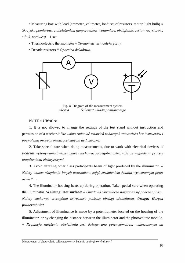
• Measuring box with load (ammeter, voltmeter, load: set of resistors, motor, light bulb) //
Skrzynka pomiarowa z obciążeniem (amperomierz, woltomierz, obciążenie: zestaw rezystorów,
silnik, żarówka) – 1 szt.
• Thermoelectric thermometer // Termometr termoelektryczny
• Decade resistors // Opornica dekadowa.
-
+
A
V
Fig. 4. Diagram of the measurement system
//Rys.4 Schemat układu pomiarowego
NOTE // UWAGA:
1. It is not allowed to change the settings of the test stand without instruction and
permission of a teacher // Nie wolno zmieniać ustawień roboczych stanowiska bez instruktażu i
pozwolenia osoby prowadzącej zajęcia dydaktyczne.
2. Take special care when doing measurements, due to work with electrical devices. //
Podczas wykonywania ćwiczeń należy zachować szczególną ostrożność, ze względu na pracę z
urządzeniami elektrycznymi.
3. Avoid dazzling other class participants beam of light produced by the illuminator. //
Należy unikać oślepiania innych uczestników zajęć strumieniem światła wytworzonym przez
oświetlacz.
4. The illuminator housing heats up during operation. Take special care when operating
the illuminator. Warning! Hot surface! // Obudowa oświetlacza nagrzewa się podczas pracy.
Należy zachować szczególną ostrożność podczas obsługi oświetlacza. Uwaga! Gorąca
powierzchnia!
5. Adjustment of illuminance is made by a potentiometer located on the housing of the
illuminator, or by changing the distance between the illuminator and the photovoltaic module.
// Regulacja natężenia oświetlenia jest dokonywana potencjometrem umieszczonym na

Measurement of photovoltaic cell parameters // Badanie ogniw fotowoltaicznych
11
obudowie oświetlacza lub poprzez zmianę odległości pomiędzy oświetlaczem, a modułem
fotowoltaicznym.
3.1. Preparation the test stand to work // Przygotowanie stanowiska do
pracy:
1. Check the correctness of all electrical and mechanical connections. In the case of any
signs of incorrect connection of elements in the test stand, this fact should be reported
to the person conducting the classes. // Należy sprawdzić poprawność wszystkich
połączeń elektrycznych i mechanicznych. W razie jakichkolwiek oznak niepoprawnego
połączenia elementów na stanowisku, należy zgłosić ten fakt osobie prowadzącej
zajęcia.
2. Place the solar panel and the lamp in a distance of approx. 0.5 m. // Ustawić panel
fotowoltaiczny i oświetlacz w odległości ok. 0,5 m
3. Connect the lamp cable to the power supply (230 V AC) and start measuring
instruments. // Włączyć do sieci (230 V AC) przewód zasilający oświetlacz i przyrządy
pomiarowe.
4. Measure and note the surface of the solar panels in the table. // Zmierzyć i zanotować
w tabeli powierzchnię paneli fotowoltaicznych.
3.2. Examination of current-voltage characteristics of PV panels // Badanie
charakterystyki prądowo-napięciowej paneli PV
The purpose of the exercise is to examine the work of the photovoltaic panel for selected
load values at a set value of illuminance. // Celem ćwiczenia jest zbadanie pracy panelu
fotowoltaicznego dla wybranych wartości obciążenia przy ustalonej wartości natężenia
oświetlenia.
1. Set the position of lamp, do not change it during measurements. Measure the
illuminance with a meter (lux meter) in several places on the surface of a photovoltaic
panel. // Ustawić położenie lampy, nie zmieniaj go w trakcie pomiarów. Dokonać
pomiaru natężenia oświetlenia miernikiem (luksomierzem) w kilku miejscach na
powierzchni panelu fotowoltaicznego.
2. Starting from the maximum value of the current flowing through the load, perform 10
to 15 measurements of the current I and voltage U by changing load resistance. At the

Measurement of photovoltaic cell parameters // Badanie ogniw fotowoltaicznych
12
same time, measure the temperature t on the back side of the solar panel. // Zaczynając
od maksymalnej wartości prądu płynącego przez obciążenie wykonać 10-15 pomiarów
wartości natężenia prądu I, napięcia U przy zmianie rezystancji obciążenia.
Równocześnie mierzyć temperaturę t na tylnej ścianie panelu fotowoltaicznego.
3. Place the measured values in table 5 // Zmierzone wartości umieścić w tabeli 5.
Table 5
L.p.
Illuminance
// Natężenie
oświetlenia
Ev (lux)
PV module
temperature //
Temperatura
modułu PV
t (°C)
Current //
Natężenie
prądu
I’ (A)
Voltage //
Napięcie
U’ (V)
Power //
Moc
wydzielona
P (W)
Load
resistance //
Rezystancja
obciążenia
R (Ω)
1
2
3
4
5
6
7
8
9
10
11
12
13
14
15
4. For resistance R = 0 Ω, measure and record the short circuit current Isc of the PV
module. // Dla rezystancji R=0 Ω zmierzyć i zanotować natężenie prądu zwarcia Isc
modułu PV.
5. For the resistance R = ∞, measure and record the open circuit voltage Uoc of the PV
module. // Dla rezystancji R=∞ zmierzyć i zanotować napięcie układu otwartego Uoc
modułu PV.
6. Correct measured values of current and voltage due to the panel temperature changes
in relation to the STC temperature, according to the following relationships: //
Skorygować zmierzone wartości natężenia prądu i napięcia ze względu na zmianę
temperatury panelu w stosunku do temperatury STC według poniższych zależności:

Measurement of photovoltaic cell parameters // Badanie ogniw fotowoltaicznych
13
𝐼 = 𝐼′ +𝛼
100∙ 𝐼𝑆𝐶 ∙ (𝑇 − 𝑇′)
𝑈 = 𝑈′ − 𝑅𝑆 ∙ (𝐼 − 𝐼′) − 𝜅 ∙ 𝐼 ∙ (𝑇 − 𝑇′) +𝛽
100∙ 𝑈𝑂𝐶 ∙ (𝑇 − 𝑇′)
where // gdzie:
I’, U’ – measured values // zmierzone wielkości
I, U – corrected values // skorygowane wielkości
T’ – measured temperature of the PV module // zmierzona temperatura panelu PV
T – STC temperature // temperatura STC
α – temperature coefficient of the short-circuit current // współczynnik temperaturowy
natężenia prądu (%ISC/°C)
β – temperature coefficient of the open-circuit voltage // współczynnik temperaturowy
napięcia (%UOC/°C)
RS – series resistance of the PV module // rezystancja szeregowa panelu PV
κ – curve correction factor // współczynnik korekcyjny krzywej.
Table 6 Coefficients //
Współczynniki
(GSTC = 1000 W/m2)
Monocrystalline cells
// Ogniwa
monokrystaliczne
Policrystalline cells //
Ogniwa
polikrystaliczne
Amorphous cells //
Ogniwa amorficzne
α (%ISC/°C) 0,03 0,05 0,08
β (%UOC/°C) -0,33 -0,36 -0,4
RS (Ω) 0,3 0,4 8
κ (Ω/°C) 0,004 0,001 0
7. Calculate the values of the power P and the resistance R of the load. // Obliczyć wartość
wydzielonej mocy P i rezystancji R obciążenia.
𝑃 = 𝑈 ∙ 𝐼 ; 𝑅 =𝑈′
𝐼′
8. The results of calculations should be presented in a one graph in the form of curves I
= f(U) and P = f(U). An example of the characteristics and the way to determine the
MPP point is shown in Fig. 5 // Uzyskane wyniki obliczeń przedstawić na jednym
wykresie w postaci krzywych I = f(U) i P = f(U). Przykład charakterystyk i sposób
określania punktu MPP przedstawia rys. 5.
9. Determine the maximum power point MPP, i.e. the point on characteristics, in which
the module produces the most power under given lighting and load conditions. //
Określić punkt mocy maksymalnej MPP, czyli punkt na charakterystykach, w którym
panel produkuje najwięcej mocy w danych warunkach oświetlenia i obciążenia.

Measurement of photovoltaic cell parameters // Badanie ogniw fotowoltaicznych
14
Fig. 5. Characteristics I = f(U), P = f(U). Determination of the maximum power point MPP
// Rys.5 Charakterystyki I = f(U), P = f(U). Wyznaczanie punktu mocy maksymalnej MPP
10. Determine the efficiency η of the PV module using the formula // Wyznaczyć
sprawność η modułu PV, korzystając z zależności:
𝜂 =𝑈𝑀𝑃𝑃 ∙ 𝐼𝑀𝑃𝑃
𝐺0 ∙ 𝐴∙ 100
where // gdzie:
Impp (A) – measured current at MPP // zmierzony prąd w punkcie MPP
Umpp (V) – measured voltage at MPP// zmierzone napięcie w punkcie MPP
A (m2) – area of PV module // powierzchnia modułu PV
G0 (W/m2) – average irradiance (can be calculated from approximate dependence) //
średnie natężenie promieniowania (można obliczyć z przybliżonej zależności):
𝐺0 = 0,72 ∙ 𝐸𝑣0,625
11. Calculate the fill factor FF using the following formula // Wyznaczyć współczynnik
wypełnienia FF, korzystając z zależności:
𝐹𝐹 =𝑈𝑀𝑃𝑃 ∙ 𝐼𝑀𝑃𝑃
𝑈𝑂𝐶 ∙ 𝐼𝑆𝐶
For calculations, use the currents and voltages obtained from the characteristics of the tested
photovoltaic cell. // Do obliczeń wykorzystać wartości prądów i napięć otrzymane z
charakterystyk badanego ogniwa fotowoltaicznego.
12. Summary of results // Podsumowanie wyników.
Tabela 7

Measurement of photovoltaic cell parameters // Badanie ogniw fotowoltaicznych
15
A (m2) Isc (A) Uoc (V) Impp (A) Umpp (V) Pmax (W) η (%) FF ( - )
13. Measurements can be made for several selected illuminance values and then plot a
family of curves I = f (U). When describing the curves specify the illuminance values
Ev // Pomiary można wykonać dla kilku wybranych wartości natężenia oświetlenia i
wykreślić rodzinę krzywych I = f(U). Przy opisywaniu krzywych podać wartości
natężenia oświetlenia Ev.
3.3. Determining the relationship between the PV module power and the
angle of inclination α // Wyznaczanie zależności mocy modułu PV od
kąta ustawienia α
The aim of the exercise is to examine the dependence of the module’s power on the
inclination angle relative to the light source // Celem ćwiczenia jest zbadanie zależności mocy
panelu fotowoltaicznego od jego kąta ustawienia względem źródła światła.
1. Set the position of lamp, do not change it during measurements. Measure the
illuminance with a meter (lux meter) in several places on the surface of a photovoltaic
panel. // Ustawić położenie lampy, nie zmieniaj go w trakcie pomiarów. Dokonać
pomiaru natężenia oświetlenia miernikiem (luksomierzem) w kilku miejscach na
powierzchni panelu fotowoltaicznego.
2. Set the panels in such a way that the angle α (between the light source and the normal
to the panel) is equal to 0 // Ustawić panele w taki sposób, aby kąt α (pomiędzy żródłem
światła a normalną do panelu) wynosił 0
3. Determine the current-voltage characteristics for the angle α = 0° // Wyznaczyć
charakterystykę prądowo-napięciową dla kąta α = 0°.
4. Change the angle of inclination by 5°. Note the values of current I and voltage U. //
Zmieniać nachylenie o 5°. Notować wartości natężenia prądu I i napięcia U.
5. Put the measured values in table 8 // Zmierzone wartości umieścić w tabeli 8.
6. Draw the characteristics I = f(cos α) and P = f(cos α). // Wykreślić charakterystyki
I = f(cos α) oraz P = f(cos α).

Measurement of photovoltaic cell parameters // Badanie ogniw fotowoltaicznych
16
Table 8
L.p.
Angle of
inclination //
Kąt nachylenia
α (°)
Illuminance //
Natężenie
oświetlenia
Ev (lux)
Current //
Natężenie
prądu
I’ (A)
Voltage //
Napięcie
U’ (V)
Power // Moc
wydzielona
P (W)
1
2
3
4
5
6
7
8
9
10
11
12
13
14
15
3.4. The study of the photovoltaic module with partial shading of a single
cell // Badanie modułu fotowoltaicznego przy częściowym zacienieniu
pojedynczego ogniwa
The aim of the exercise is to examine the operation of the solar module at partial shading
the module's cells and at a fixed value of illuminance // Celem ćwiczenia jest zbadanie pracy
modułu fotowoltaicznego przy częściowym zacieniu ogniw modułu i przy ustalonej wartości
natężenia oświetlenia
1. Set the position of lamp, do not change it during measurements. Measure the illuminance
with a meter (lux meter) in several places on the surface of a photovoltaic panel. // Ustawić
położenie lampy, nie zmieniaj go w trakcie pomiarów. Dokonać pomiaru natężenia
oświetlenia miernikiem (luksomierzem) w kilku miejscach na powierzchni panelu
fotowoltaicznego.
2. Set the panels in such a way that the angle α is equal to 0 // Ustawić panele w taki sposób,
aby kąt α wynosił 0.
3. Cover with piece of paper the single module cell // Przysłonić kartką pojedyncze ogniwo
modułu.
Measurement of photovoltaic cell parameters // Badanie ogniw fotowoltaicznych
17
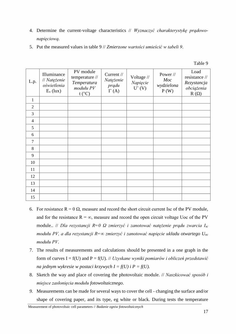
4. Determine the current-voltage characteristics // Wyznaczyć charakterystykę prądowo-
napięciową.
5. Put the measured values in table 9 // Zmierzone wartości umieścić w tabeli 9.
Table 9
L.p.
Illuminance
// Natężenie
oświetlenia
Ev (lux)
PV module
temperature //
Temperatura
modułu PV
t (°C)
Current //
Natężenie
prądu
I’ (A)
Voltage //
Napięcie
U’ (V)
Power //
Moc
wydzielona
P (W)
Load
resistance //
Rezystancja
obciążenia
R (Ω)
1
2
3
4
5
6
7
8
9
10
11
12
13
14
15
6. For resistance R = 0 Ω, measure and record the short circuit current Isc of the PV module,
and for the resistance R = ∞, measure and record the open circuit voltage Uoc of the PV
module.. // Dla rezystancji R=0 Ω zmierzyć i zanotować natężenie prądu zwarcia Isc
modułu PV, a dla rezystancji R=∞ zmierzyć i zanotować napięcie układu otwartego Uoc
modułu PV.
7. The results of measurements and calculations should be presented in a one graph in the
form of curves I = f(U) and P = f(U). // Uzyskane wyniki pomiarów i obliczeń przedstawić
na jednym wykresie w postaci krzywych I = f(U) i P = f(U).
8. Sketch the way and place of covering the photovoltaic module. // Naszkicować sposób i
miejsce zasłonięcia modułu fotowoltaicznego.
9. Measurements can be made for several ways to cover the cell - changing the surface and/or
shape of covering paper, and its type, eg white or black. During tests the temperature

Measurement of photovoltaic cell parameters // Badanie ogniw fotowoltaicznych
18
measurements can be made for shaded and non-shaded cells // Pomiary można wykonać
dla kilku sposobów przesłonięcia ogniwa – zmieniając powierzchnię i/lub kształt
przesłonięcia oraz rodzaj kartki np. biała lub czarna. W trakcie pomiarów można wykonać
pomiary temperatury ogniw zacienionych i niezacienionych.
2. THE REPORT // SPRAWOZDANIE
The report should include // Sprawozdanie powinno zawierać:
1. Title page (date of the exercise and its number, names of the participants). // Strona tytułowa
(data wykonania ćwiczenia, numer ćwiczenia, nazwiska i imiona uczestników.
2. Short theoretical introduction about photovoltaic calls and aim of the exercise. // Krótki
wstęp teoretyczny dotyczący ogniw fotowoltaicznych i cel ćwiczenia.
3. Diagram of the measuring stand with marked measurement points of specific quantities.
Description of the tested photovoltaic cell and instruments used during measurements. //
Schemat stanowiska pomiarowego wraz z zaznaczonymi miejscami pomiaru określonych
wielkości. Opis badanego ogniwa fotowoltaicznego oraz przyrządów wykorzystanych
podczas pomiarów.
4. Tables with measurement results and calculation with the used formulas // Tabelę wyników
pomiarowych i obliczeń oraz wzory używane do obliczeń.
5. Characteristics I=f(U) i P=f(U) with marked characteristic points. // Charakterystyki I=f(U)
i P=f(U) wraz z zaznaczonymi charakterystycznymi punktami.
6. Tables with determined cell parameters Isc, Uoc, Impp, Umpp, Pmax, η, FF. Comparison with
the rated data. // Tabele z wyznaczonymi parametrami ogniwa: Isc, Uoc, Impp, Umpp, Pmax, η,
FF. Porównanie z danymi znamionowymi.
7. Observations and conclusions. // Spostrzeżenia i wnioski
The report should be printed double-sided. // Sprawozdanie powinno być drukowane
dwustronnie.
Bibliography // Bibliografia
Vasilis M. Fthenakis, Paul A. Lynn: Electricity from Sunlight: Photovoltaic-Systems
Integration and Sustainability, 2nd Edition. ISBN: 978-1-118-96378-4, Jan 2018
Konrad Mertens: Photovoltaics: Fundamentals, Technology and Practice. ISBN: 978-1-118-
84339-0, Nov 2015