measurement of birefringence for optical recording of disk substrates
TRANSCRIPT

Measurement of birefringencefor optical recording of disk substrates
Hong Fu, S. Sugaya, J. K. Erwin, and M. Mansuripur
We experimentally investigate the birefringence of bare and coated substrates for magneto-opticalrecording, using ellipsometry at wavelengths of 632.8 and 780 nm. The polarization rotation andellipticity of reflected or transmitted light are measured for different incident angles and for differentorientations of the incident linear polarization. The measured data are then fitted by the MULTILAYERcomputer program, which solves the Maxwell equations for a plane wave propagating in a multilayerstructure. This approach makes it possible to determine, with high accuracy, the orientations of theprincipal axes of the substrate and the corresponding refractive indices. The results show that one of theprincipal axes is always along the substrate's normal direction, but the orientations of the in-planeprincipal axes can be much different from the radial and track directions. A special feature of theellipsometers that were used is that a glass hemisphere is placed in contact with the substrate to eliminaterefraction of the incident beam. This enables a maximum propagation angle of 70° (with respect to thenormal) in the substrate and hence increases the measurement sensitivity. Certain anomalies have beenobserved, which we believe are associated with the variation of birefringence properties along thethickness direction.
1. Introduction
Birefringence is a phenomenon observed in opticallyanisotropic media in which the refractive indicesdepend on the polarization direction. The polariza-tion-dependent phase shifts that are due to birefrin-gence of the plastic substrates of magneto-optical(MO) disks degrade the performance of MO readoutsystems.1-7 As the MO data storage systems progresstoward high resolution, ultrafast speeds, and shorterwavelength, birefringence will become an increas-ingly important problem.
Birefringence in plastic substrates is due to prefer-ential molecular orientation and internal stresses.The refractive index is higher when the electric fieldof the light beam is parallel to the molecular chaindirection. For an injection-molded polycarbonate(PC) substrate the fluid shear during the moldingprocess acts to align the PC chains in the plane of thedisks. Therefore the refractive indices n, and n2 forthe in-plane electric-field components El and E2 arelarger than n3 for the perpendicular component E3 .
The authors are with the Optical Sciences Center, University ofArizona, Tucson, Arizona 85721-0001.
Received 7 May 1993, revised manuscript received 16 August1993.
0003-6935/94/101938-12$06.00/0.© 1994 Optical Society of America.
Characterization of substrate birefringence has beenthe subject of several papers,6 '8-" which confirmedthe above picture and showed that n, - n3 is of theorder of 5 x 10⁻⁴, whereas n1 - n2J is of the order of10-5 or less. However, the previous research islimited in the following aspects: First, the for-mula8 1 by which the experimental data were pro-cessed applies only to transparent single-layer mediaunder the assumption that the principal axes of theindex ellipsoid are fixed in the radial, track, andperpendicular directions. The phase shifts that aredue to the multilayers coated on the substrate andalso the tilt of the index ellipsoid could not be takeninto account. Second, because of refraction at theinterface between air and substrate, the propagationangle in the substrate is small. For example, a 700incident angle in air yields a 36.5 angle in the PCsubstrate (n = 1.58). So the beam possesses only asmall E3 component, and the experimental sensitivityto n3 is limited.
The present paper describes our measurements ofthe substrate birefringence with one ellipsometerwith wavelengthX = 632.8 nm and another with X =780 nm. The measured quantities are the rotationangle and ellipticity of the reflected or transmittedlight caused by the substrate's birefringence. Weremove the first restriction of the previous researchby fitting the experimental data with the MULTILAYERcomputer program, which solves Maxwell equations
1938 APPLIED OPTICS / Vol. 33, No. 10 / 1 April 1994

for the plane wave propagating in a multilayer struc-ture including the substrates This enables us todetermine the three principal axes of the substrateand the corresponding refractive indices. To over-come the second limitation, we have placed a hemi-spherical glass lens atop the substrate to eliminaterefraction. A maximum propagation angle of 70 inthe substrate has thus been achieved. The mea-sured materials include glass, PC plastic (bare andcoated), and amorphous polyolefin (APO) plastic (bare).
To study the effects of grooves on birefringence, wemeasured regions with or without grooves. Forregions with grooves, the grooves were either filledwith index-matching fluid or left empty. We alsoused different angles between the plane of incidenceand the direction of grooves in the measurements.Certain anomalies have been observed that depend onthis angle. We describe some of the anomalousbehaviors in Section 3.
This paper is organized as follows: Section 2describes the two elipsometer systems, the measure-ment procedures, and the data analysis. The mea-surement results are described in Section 3. Sensi-tivity of the measurements to the birefringenceparameters is discussed in Section 4. Section 5contains the concluding remarks.
2. Ellipsometer Systems and the Measurement Method
A. VAE633 System
Figure 1 shows the experimental setup. The lightsource is a He-Ne laser with X = 632.8 nm. As thebeam first passes through the polarizer and thequarter-wave plate (QWP) whose fast axis is at 450 tothe transmission axis of the polarizer, it becomescircularly polarized. The second polarizer selectsthe linear polarization direction to be incident uponthe sample. A commercial hemispherical plano-convex glass lens (Melles Griot Co. 01 LPX 041) isplaced in contact (using index-matching fluid) withthe surface of the sample. The height of the hemi-sphere is slightly less than the radius of the spherical
Plastic Substrate
Hemisphere
ei_ PS. S.
PX/4 Plate
PBS
Wollaston Prism 14 Plate
Polarizer
Detectors He-Ne Laser
)1Fig. 1. VAE633 system setup for the variable-angle ellipsometer,with A = 632.8 nm. PBS, polarizing beam splitter.
surface and is mounted in such a way that thegeometric center of the spherical surface is on theback side of the substrate. The light enters nor-mally into the hemisphere, goes through the sub-strate, and is reflected from the back side of thesubstrate. After reflection, the beam passes throughanother QWP with an adjustable fast-axis orientation.The beam then goes through a Wollaston prism,which can be rotated about the beam. Finally, thetwo beams of mutually perpendicular polarization aredetected by the photodetectors.
The hemispherical lens eliminates refraction at theair-substrate interface and thus enables a largerpropagation angle within the substrate. For ex-ample, in PC substrate with n = 1.58, without theglass hemisphere one can reach a maximum angle of390 at grazing incidence (i.e., inc = 900), whereaswith the hemisphere in place (nsphere = 1.52 at X = 633nm, and nsphere = 1.51 at = 780 nm), the propaga-tion angle inside the substrates is 640 at Oin, = 700.Mechanical obstruction of this particular setup in thereflection measurement limits the range of the inci-dence angle to 100 < Oinc < 700.
By opening the two arms into a straight line, theVAE633 system can also be used to measure thetransmitted light. In this case we remove the hemi-sphere and mount the sample to realize normalincidence. This transmission mode was found to bevery suitable to measure the small in-plane birefrin-gence, because the beam does not interact with thevertical birefringence, which is usually 2 orders ofmagnitude larger than the in-plane birefringence.We also used this configuration to measure the glasshemispherical lens and confirmed that it does notpossess any observable birefringence.
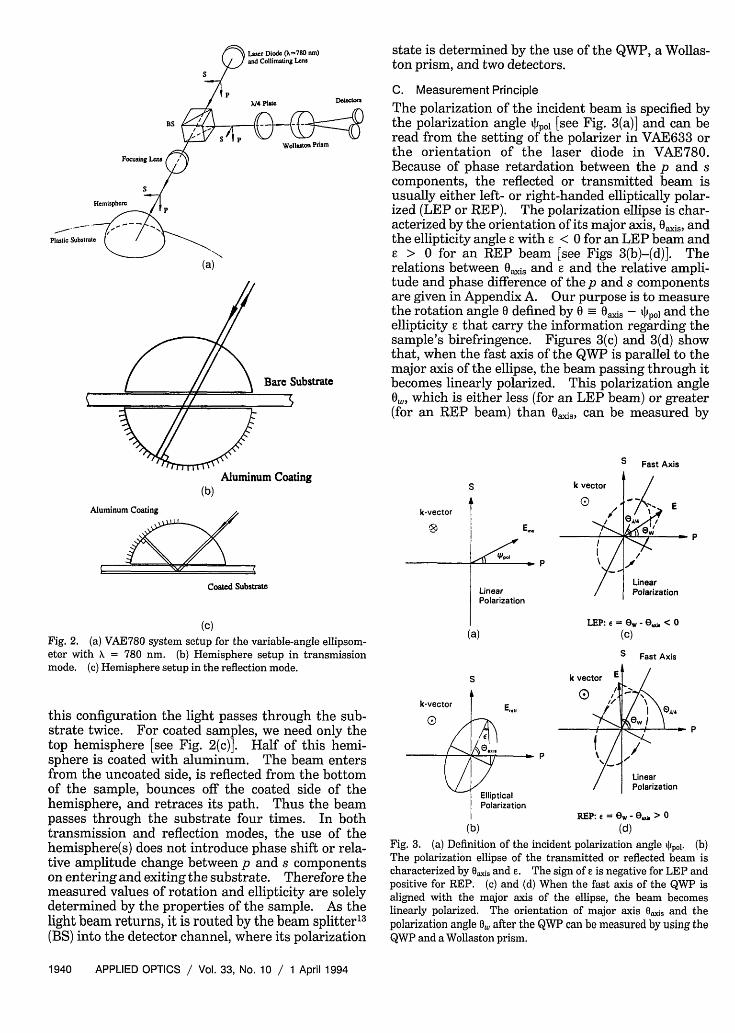
B. VAE780 System
The setup is schematically shown in Fig. 2(a). Theoperation principle is similar to the VAE633 system.One of the main differences is that all the movingparts are mounted in one arm, which can be rotatedin both the polar and azimuthal directions. Conse-quently, the alignment of the system is easier tomaintain, and normal incidence can be realized.The freedom of two-dimensional rotation is particu-larly valuable because it allows us to measure thesample at different polar incident angles Oinc as wellas azimuthal incident angles i,, relative to the radialdirection on the disk. The linearly polarized lightfrom the laser diode (X = 780 nm) passes through thebeam splitter and enters normally to the hemispherebefore it reaches the sample. The direction of inci-dent polarization is controlled by rotating the laser inits socket. The hemisphere is used in different ways,depending on whether the sample is transparent orreflective. For transparent samples, two hemi-spheres are used [see Fig. 2(b)]. The hemisphere onthe top is transparent and is used to eliminaterefraction. The hemisphere at the bottom is coatedwith aluminum and reflects the beam normally sothat the light goes back along the incident path. In
1 April 1994 / Vol. 33, No. 10 / APPLIED OPTICS 1939
Aluminum Coating
state is determined by the use of the QVVP, a Wollas-ton prism, and two detectors.
C. Measurement PrincipleNW- The polarization of the incident beam is specified by
the polarization angle i~pol [see Fig. 3(a)] and can beread from the setting of the polarizer in VAE633 orthe orientation of the laser diode in VAE780.Because of phase retardation between the p and scomponents, the reflected or transmitted beam isusually either left- or right-handed elliptically polar-ized (LEP or REP). The polarization ellipse is char-acterized by the orientation of its major axis, Oaxis, andthe ellipticity angle E with < 0 for an LEP beam and
> 0 for an REP beam [see Figs 3(b)-(d)]. Therelations between Oajis and E and the relative ampli-tude and phase difference of the p and s componentsare given in Appendix A. Our purpose is to measurethe rotation angle 0 defined by 0 - Oa,is - Spot and theellipticity E that carry the information regarding thesample's birefringence. Figures 3(c) and 3(d) showthat, when the fast axis of the QWP is parallel to themajor axis of the ellipse, the beam passing through itbecomes linearly polarized. This polarization angle0k, which is either less (for an LEP beam) or greater(for an REP beam) than axis, can be measured by
S Fast Axis
S
k-vector
Coated Substrate
(C)Fig. 2. (a) VAE780 system setup for the variable-angle ellipsom-eter with X = 780 nm. (b) Hemisphere setup in transmissionmode. (c) Hemisphere setup in the reflection mode.
k vector
0
LinearPolarization
(a)
I
this configuration the light passes through the sub-strate twice. For coated samples, we need only thetop hemisphere [see Fig. 2(c)]. Half of this hemi-sphere is coated with aluminum. The beam entersfrom the uncoated side, is reflected from the bottomof the sample, bounces off the coated side of thehemisphere, and retraces its path. Thus the beampasses through the substrate four times. In bothtransmission and reflection modes, the use of thehemisphere(s) does not introduce phase shift or rela-tive amplitude change between p and s componentson entering and exiting the substrate. Therefore themeasured values of rotation and ellipticity are solelydetermined by the properties of the sample. As thelight beam returns, it is routed by the beam splitter' 3
(BS) into the detector channel, where its polarization
k-vector
0
k vector E
I/Vi
P \
EllipticalPolarization
(b)
I OA�4
P
/
LinearPolarization
REP: e = O - , > 0(d)
Fig. 3. (a) Definition of the incident polarization angle S,,. (b)The polarization ellipse of the transmitted or reflected beam ischaracterized by Oasis and E. The sign of e is negative for LEP andpositive for REP. (c) and (d) When the fast axis of the QWP isaligned with the major axis of the ellipse, the beam becomeslinearly polarized. The orientation of major axis Oi and thepolarization angle 0, after the QWP can be measured by using theQWP and a Wollaston prism.
1940 APPLIED OPTICS / Vol. 33, No. 10 / 1 April 1994
Laser Diode (-780 nm)and Collimating Lens
X/4 Plate
BS
WoaUto Prism
Forwing Lns
S
Hemisphere
Plastic Substrate
Bare Substrate
(b)E
P
/1
LinearPolarization
LEP: e = eW - e, < 0(c)
S Fast Axis
S'l b
l -X l X b
/ -red I / b
IIk

rotating the Wollaston prism until one of the detec-tors receives no light. The ellipticity is then given by
= 3 - Oaxi. In practice one needs to adjust theQWP and the Wollaston prism simultaneously toachieve the extinction. In our case of manual opera-tion, each measurement of 0 ais and O (i.e., 0 and £3)
takes approximately several seconds. The error forthe measured value of E, obtained using this method isusually less than 1, as estimated from repeatedmeasurements. The error for 0 depends on thevalue of e. For I I, < 40°, an error of less than 10 canbe achieved. For I s > 400, the ellipse is close to acircle, and the orientation of the major axis is hard tomeasure. The repeatability of 0 in such cases iswithin several degrees.
D. Data Fitting with the MULTILAYER Program
The first part of the MULTILAYER program' 2 solves theMaxwell equations for a plane wave that is obliquelyincident upon a multilayer structure consisting of agiven number of layers. Each layer is characterizedby its dielectric tensor and thickness. With ad-equate restrictions on the tensor elements, differenttypes of media (isotropic, birefringent, MO, etc.) canbe described. Figure 4(a) shows the quadrilayerstructure of a typical MO disk. This structure isused in data fitting for coated substrates. The plas-tic substrate is assumed to have uniform birefrin-gence properties and can be described by a singlelayer. The hemisphere material and the index-matching fluid (nfluid = 1.52) are treated as the me-dium of incidence. Because the optical paths inVAE633 and those in the transmission and reflectionmodes of VAE780 are different, several versions ofthe MULTILAYER program were used in the data analy-S1S.
The second part of the program searches for thebest values of unknown parameters by minimizingthe average fitting error defined by
1 (N) 1/2e= () [(0i(exp) - 0,(cal))2 + ((exP) - (cal))2]
(1)
In Eq. (1) the superscript exp stands for experimentaldata, the superscript cal stands for calculated data,and N is the total number of measurements for agiven sample. The unknown parameters are therefractive indices, the orientation angles of the princi-pal axes of the ellipsoid of birefringence, and thestructure parameters of the MO multilayer.
In Fig. 4(a) X and Y denote the in-plane radial andtrack directions of the optical disk, respectively, and Zis the normal direction. In addition to the incidentangle Oinc, we use (Dinc to specify the azimuth of theincident k vector. For all the samples we found thatone principal axis (3) is always along the perpendicu-lar direction (within 1), but the in-plane axes (1 and2) may be rotated in the X-Y plane [see Fig. 4(b)].To be specific, we let 1 be the in-plane axis with the
Substrate
Dielectric
Magneto-optic
Dielectric
Reflector
(a)
Z,3
2
y
#1311M
X
(b)
Fig. 4. (a) Quadrilayer structure of the MO disk used in fitting thedata for the coated substrate. (b) The in-plane principal axes arefound to be rotated for some substrates, but the third axis is alwaysfound to be perpendicular to the plane of the substrate.
larger refractive index and use Iinplane to denote thein-plane rotation of axis 1 from the radial direction.
There is one aspect that is not taken into account inthe MULTILAYER program; i.e., the actual laser beam isnot a plane wave but a focused beam with a 0.5-mmdiameter that converges to a 50-pm spot at thebottom of the substrate. For thick samples at ob-lique incidence, the two reflected beams from thefront and back surfaces are spatially separate and donot interfere with each other, whereas in the programthe two beams overlap. However, because the reflec-tion at the interface between the hemisphere and thesubstrate is weak, the interference causes only smallfluctuations in the calculated curves. Therefore theplane-wave approximation is acceptable. To removethe fluctuation, the angle inside the substrate can beadjusted according to Snell's law, and thus the differ-
1 April 1994 / Vol. 33, No. 10 / APPLIED OPTICS 1941

Table 1. Summary of the Measurement Resultso
FittingSample X (nm) _inplaneb (deg) ni n1 - n2c n1 - n3d d(ni - n 2)e (nm) d(n, - n3 ) (nm) Error (deg)
Glass slide 633 -9 1.54 0.6 x 10⁻⁵ -1 X 10⁻⁶ 7.3 -1.2 0.8PC3.5B01 633 2 1.58 1.8 x 10⁻⁵ 5.87 x 10⁻⁴ 21.1 704.5 1.7PC3.5B02 633 0 1.58 0.3 x 10⁻⁵ 6.26 x 10⁻⁴ 3.6 751.4 3.8PC3.5B02 780 46 1.58 1.6 x 10⁻⁵ 6.20 x 10⁻⁴ 18.7 744.2 2.7PC5.25B01 633 -7 1.58 1.6 x 10⁻⁵ 6.02 x 10⁻⁴ 19.2 722.4 4.3PC5.25B01 780 58 1.58 1.2 x 10⁻⁵ 6.11 x 10⁻⁴ 13.8 733.4 2.9PC5.25B02 633 2 1.58 2.2 x 10⁻⁵ 5.83 x 10⁻⁴ 26.3 699.4 4.7AP05.25B01 633 -73 1.50 0.4 x 10⁻⁵ 1.3 x 10⁻⁵ 4.8 15.6 1.0PC3.5C01 633 -7 1.58 1.5 x 10⁻⁵ 5.68 x 10⁻⁴ 17.4 681 2.7PC3.5C02 633 -7 1.58 2 x 10⁻⁵ 5.51 x 10⁻⁴ 23.9 661.3 7.2PC5.25C01 633 8 1.58 0.9 x 10⁻⁵ 4.61 x 10⁻⁴ 11.3 552.6 1.7PC5.25C02 633 -27 1.58 1.4 x 10⁻⁵ 3.40 x 10⁻⁴ 16.8 408 3.6PC5.25C03 633 12 1.58 1.9 x 10⁻⁵ 3.47 x 10⁻⁴ 22.8 416.8 6.6
aThe principal axis 3 is along the substrate's normal direction in all cases.bRotation angle between the in-plane principal axis 1 and radial direction.cIn-plane birefringence.dVertical birefringence.ed = 1.2 is the substrate's nominal thickness.
ence between nsphere and nsub (= 1.58) is accounted forproperly.
3. Measurement Results
The measured samples include a front-surface alumi-num mirror, a glass microscope slide, two 3.5" polycar-bonate bare substrates (PC3.5B01 and PC3.5B02),two 5.25" polycarbonate bare substrates (PC5.25B01and PC5.25B02), one 5.2" amorphous polyolefin sub-strate (AP05.25B01), two 3.5" MO disks (PC3.5C01and PC3.5C02), and three 3.5" disks (PC5.25C01,PC5.25C02, PC5.25C03). In this notation PC ispolycarbonate, APO is amorphous polyolefin, 3.5 and5.25 are disk diameters in inches, B is bare substrate,C is coated substrate, and 01, 02, and 03 are the serialnumbers of the samples. The main results of thesemeasurements are summarized in Table 1. In Figs.5-13 we use 0 to represent the measured value of 0and * to represent .
A. Aluminum Mirror and Glass Microscope Slide
Our purpose in measuring these two samples was tocheck the basic functions and accuracy of the ellipsom-eters. For the aluminum sample the measurementwas performed without using the glass hemisphericallens, and a maximum incidence angle of 800 could berealized. Figure 5 shows the measured and matched0 and 13 as functions of the incident angle 0 inc forVAE633. The incident polarization angle iIp0l was600. The rotation and the ellipticity are caused bythe complex refractive index n + ik of aluminum.The best match gives n = 1.40 and k = 6.42. Theaverage fitting error is 0.50.
The glass microscope slide has a thickness d = 1.2mm. Glass is believed to be isotropic, with a refrac-tive index close to that of the hemisphere and index-matching fluid. So the optical path is simple (e.g., nomultiple reflections), and the problem should bedescribed by the well-known formulas for reflectivity
at a single interface.1415 Figures 6 show 0 and 1 asfunctions of the incident angle in the range 10 <0rnc < 700 for tpol = 450. The measured data in Figs.6(a) and 6(b) are the same. We obtained the calcu-lated curves in Fig. 6(a) by assuming that the glass isisotropic. The match gives nglas = 1.54. The aver-age fitting error is 1.90. It can be seen that therotation can be matched very well, but the nonzeroellipticity for inc < 41° (the critical angle of totalinternal reflection is 41.3°) cannot be matched. Themismatch may indicate that there is a small amountof birefringence in the glass sample. As we allowedfor birefringence, the average fitting error dropped to0.80. The best match is shown in Fig. 6(b). Thefitted refractive indices are nj = 1.54, (n, - n2) = 6 x10⁻⁶, and (n, - n3) = - 1 x 10⁻⁶. The small fluctua-tions appearing in the calculated curves are due to theinterference of beams reflected at the front and theback surfaces of the sample.
0
a:
3
ml
o
400z
-5
-10
-15
-20
-251 0 20 30 40 50 60 70 80
INCIDENT ANGLE (DEGREES)
Fig. 5. Measured 0 (0) and E () and the best fit (lines) for afront-surface aluminum mirror. Data were taken with the reflec-tion mode of VAE633.
1942 APPLIED OPTICS / Vol. 33, No. 10 / 1 April 1994
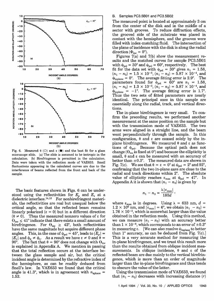
B. Samples PC3.5B01 and PC3.5B02
D -- tort depot =45° The measured point is located at approximately 3 cmfrom the center of the disk and in the middle of asector with grooves. To reduce diffraction effects,the grooved side of the substrate was placed incontact with the hemisphere, and the grooves werefilled with index-matching fluid. The intersection ofthe plane of incidence with the disk is along the radialdirection (inc = 0).
(a) Figures 7(a) and 7(b) show the measurement re-sults and the matched curves for sample PC3.5B01
D oEO o oo with tIipo = 300 and typoj = 60°, respectively. The best10 20 30 40 50 60 70 fit for the data set with Ppol = 300 gives n = 1.58,
INCIDENTANGLE(DEGREES) (n, - n2) = 1.5 x 10⁵, (n, - n3 ) = 5.87 x 10 and(a) qfinplane = 00. The average fitting error is 2.90. The
D parameters found for tlpo = 600 are nl = 1.58,0 - ~ | llt,=45' (n, - n2) = 1.3 x 10⁻⁵, (n, - n3 ) = 5.87 x 10⁻⁴, andD tpJiinplane = -1. The average fitting error is 1.70.
Thus the two sets of fitted parameters are nearlyD \ identical. The principal axes in this sample areD \ essentially along the radial, track, and vertical direc-o \ tions.D \ The in-plane birefringence is very small. To con-o \ firm the preceding results, we performed another
D measurement at the same position on the sample but(b) with the transmission mode of VAE633. The two
arms were aligned in a straight line, and the beamD 0 20 30 40 50 60 70 went perpendicularly through the sample. In this1I 0 20 3 0 40 so 60 7 0 configuration, 0 and 13 are caused solely by the in-
INCIDENTANGLE (DEGREES) plane birefringence. We measured 0 and 13 as func-(b) tions of ~Ilpoj- Because the optical path does not
Measured (0) and () and the best fit for a glass change (0jinc is fixed at 00) and because the ellipticity iscope slide. (a) The slide is assumed to be isotropic in the sution. (b) Birefringence is permitted in the calculation. smallthand0E3canTbemeasureddtaaraofrere taken with the reflection mode of VAE633. Small better than ± 0.3. The measured data are shown inltions appearing in the calculated curves are due to the Fig. 7(c). We see that 0 = E = 00 at IJpol = 20 and 920,rence of beams reflected from the front and back of the confirming that the two in-plane axes are close to the
radial and track directions within 20. The absolutevalue of ellipticity reaches Emac at qIpo = 47°. InAppendix A it is shown that (n, - n2 ) is given by
The basic features shown in Figs. 6 can be under-stood using the reflectivities for Ep and Es at adielectric interface.'4 "15 For nonbirefringent materi-als, the reflectivities are real but unequal below thecritical angle, so that the reflected beam remainslinearly polarized ( = 0) but in a different direction(0 • 0). Thus the measured nonzero values of 13 forOin, < 411' indicate that there exists a small amount ofbirefringence. For Oic > 42°, both reflectivitieshave the same magnitude but acquire different phaseangles. This, in the case of tpol = 450, leads to I Ep I =I Es I and p • AS. As a result we have • O and 0 =900. The fact that 0 = 900 does not change with Oincis explained in Appendix A. We mention in passingthat the total reflection occurs at the interface be-tween the glass sample and air, but the criticalincident angle is determined by the refractive index ofthe hemisphere, as can be readily deduced fromSnell's law. In VAE633 we found that the criticalangle is 41.30, which is in agreement with nsphere =1.52.
X I maxIn - n,2 180d
where Emc is in degrees. Using X = 633 nm, d =1.2 X 10⁶ nm, and I Ima, | = 60, we obtain (n, - n2 ) =
1.76 x 10⁻⁵, which is somewhat larger than the valueobtained in the reflection mode. Using this method,we can measure (n, - n2) with an accuracy betterthan 1 x 10⁻⁶, which corresponds to an error of + 0.30in measuring 1. [We can also resolve Iinplane to betterthan 1 accuracy, as can be deduced from Fig. 7(c).]This is a very accurate method for measuring thein-plane birefringence, and we trust this result morethan the results obtained from oblique incident mea-surements. In oblique incidence, 0 and 1 of thereflected beam are due mainly to the vertical birefrin-gence, which is more than an order of magnitudelarger than the in-plane birefringence and thus tendsto obscure the value of the latter.
Using the transmission mode of VAE633, we foundthat (n, - n2) decreases with increasing distance (r)
1 April 1994 / Vol. 33, No. 10 / APPLIED OPTICS 1943
i,,c-2Cw
o -iCO -2C
o -3Ca.I -4C
wa -SC
z-2
4Zz -6C0a -7C
1 -
E _11
0
ro-9c
'Uor -1
0
o -81z9
Fig. 6.micros(calculalData fluctuainterfeisample

plane principal axes in these three positions areessentially along the radial and track directions.
Some of the features shown in Figs. 7 are commonto all the substrates we have investigated and can beeasily explained. First, the absolute values of 0 and 3are small at small Oinc The reason is that at close tonormal incidence the beam mainly senses the small
0 r V V in-plane birefringence. The second feature is that0 E = 0 holds for all pol at some incident angles. The0 (a) , = 300 reason is that the phase difference between p and s at0 [ these incident angles is equal to an integer multiple of0 2 Ar; the phase difference does not change with tpol; seeI 0 20 30 40 50 60 70 Eqs. (A3a) and (A3b) in Appendix A. For a bare
INCIDENTANGLE(DEGREES) substrate, both the rotation and the ellipticity can be(a) zero at some incident angles [see 0 and E at Qin = 46°,
- 57.5°, and 660 in Figs. 7(a) and 7(b)] for different IJpol.* What happens here is that the phase difference
between p and s is an integer multiple of 2rr, and therelative amplitudes do not change because of totalinternal reflection. It is also interesting to note thatthe oscillation interval, i.e., the difference betweenincident angles corresponding to adjacent peaks, de-creases with increasingOin [for example, the peaks of
00 0 13l Y I r \ in Fig. 7(a) appear atin = 220, 370, 490, 60°, and680]. This feature is related to the increased rate of
(b) = 60' 00 change of the optical path length as the incidenceangle increases. Another feature is that 0 always
20 30 40 50 60 70 shows a 900 jump when = 450; see, for example, the1I 0 20 3 0 40 5 0 60 70 data point at inc = 220 in Fig. 7(a). What happens
cIDENTANGLE (DEGREES) here is that the polarization ellipse is very close to acircle. A slight decrease in the major axis or increasein the minor axis causes exchange of the axes andleads to a 900 jump.
Sample PC3.5B02 is another substrate in the sameseries of product as PC3.5B01. We measured thesame position (3 cm from the center of the disk andthe middle of a sector with grooves) in both VAE633and VAE780 for Di,, = 00 and S1pot = 60. The datataken with VAE633 are similar to those shown in Fig.7(b). In comparison with PC3.5BO1, the fitted in-plane birefringence for PC3.5B02 is smaller, (n, -
(C) n2 ) = 0.5 x 10⁻⁵, and vertical birefringence is some-what larger, (n, - n3) = 6.26 x 10⁻⁴. For such a
0 0 20 30 40 50 60 70 80 90 small (n, - n2), the experimental sensitivity in thereflection mode is not enough to determine the
INCIDENT POLARIZATION ANGLE (DEGREES) orientations of the in-plane principal axes. Using(C) the transmission model of VAE633, we found that
Measured 0 (0) and e (0) and the best fit for sample the n =o.310t i nd of 00. PC3o5Bt201. The measured data in (a) pl = 30° and (b) qp~l = 600 (n - Q = 03 x and tNplam 0- PC3.5102ken with the reflection mode of VAE633. The discontinu- was also measured with VAE780 in the transmissioni = 22° in (a) is explained in the text. The jumps at inc = mode. Figure 8 shows the measured data and theO in, 390 are not physical, because +90 stands for the same best fit. The best match gives 44inplane = 460. Theition plane. (c) Data were measured in the transmission fitted parameters are n = 1.58, (n, - n2) = 1.6 xfVAE633, which shows explicitly that 1linplane- 2. 10-5, and (n - n3) = 6.20 x 10⁻⁴. Why the fitted
in-plane birefringence in this case is larger is notunderstood.
from the disk center. For example, we measuredthree positions in a given radial direction and ob-tained (n, - n2 ) x 105 = 1.9, 1.7, and 0.9 for r = 2.0,3.0, and 3.5 cm, respectively. This indicates that themolecular chains are better aligned along the radialdirection in the central region. The measured in-
C. Samples PC5.25B01 and PC5.25B02
Samples PC5.25B01 and PC5.25B02 are from thesame series of product. The measured point onsample PC5.25B01 was located 5 cm from the diskcenter and in the middle of a sector with grooves.The groove side faced the hemisphere and was filled
1944 APPLIED OPTICS / Vol. 33, No. 10 / 1 April 1994
00
0
0
0
0
0
6i 8
o 6R
° 4
oJ 2
a -2zZ -424 -60
osX -8-10
or 2(
u,o 1
2 CF
n -i1/
o -2C
Z -3C0
4 -4(0
orAl: -5
iaLU
WW°
o
00
4z0
cc
0
-1
-2
-3
-4
-5
-6
-7
Fig. 7.PC3.5Ewere taity atO270 andpolarizemode oJ

606i 50LU
r 40 160'
~- 30
20
I 10
a 0zz -100
- 20
or-30
-400 10 20 3 0 40 50 60 70
INCIDENTANGLE (DEGREES)
Fig. 8. Measured 0 (0) and () and the best fit for samplePC3.5B02. Data were measured with VAE780 in the transmis-sion mode.
with index-matching fluid. The measurement wasperformed with (Din = 0 and t~po = 600 in thetransmission mode of VAE780. The measured datacan be matched very well, with an average fittingerror of 2.90. The fitted parameters are n = 1.58,(n, - n2) = 1.2 x 10⁻⁵, (n, - n3) = 6.11 x 10⁻⁴, and1Pinplane = 580.
This sample was also measured in the reflectionmode of VAE633 at 4cinc = 0. However, the mea-sured data cannot be matched very well. To makesure this is not due to defects of the sample, werepeated the measurement for different positions.A typical example for a point located 3 cm from thedisk center is shown in Figs. 9. Figure 9(a) corre-sponds to the case in which the grooves were filledwith index-matching fluid, and Fig. 9(b) correspondsto the case in which the grooves were on the oppositeside of the substrate from the hemisphere and wereleft empty. Except for a few points at Oinc Ž 600, themeasured data in these cases are very similar. Thefitted parameters are n = 1.58, (n, - n2) = 1.6 x10⁻⁵, (n, - n3) = 6.02 x 10⁻⁴, and tinplane = -7The mismatch occurs for Oinc 250, and at someincident angles it is larger than 100. This mismatchseems to be associated with the grooved region,because it disappears in regions in which there are nogrooves (see the results for sample PC5.25B02, below).However, because the data are basically the same forfluid-filled and empty grooves, the mismatch cannotbe a direct result of the physical presence of thegrooves. We expect this problem to be associatedwith the nonuniform distribution of birefringencethrough the thickness of the substrate.
For sample PC5.25B02 we measured a regionwithout grooves: a point located 2.5 cm from thecenter of the disk with VAE633 for Ijpoj = 300, 45, 600,at Din = 900. Figures 10(a)-10(c) show the mea-sured data and the fits. The fitted parameters basedon data taken for 100 < inc < 53 with 4ppoj = 300, 450,and 600 are n = 1.58, (n, - n2) = 2.2 x 10⁻⁵,(n, - n3) = 5.83 x 10⁻⁴, and 1linplane = 1.60. Nomatch has been found for Oic > 540 (not plotted).
40
LU
a
0
LUaz4z0I
20
0
-20
-40
-60
-80 10
40
LU
.
LUa2z0I
0
20
0
-20
-40
-60
-80
20 30 40 50 60 70
INCIDENT ANGLE (DEGREES)(a)
10 20 30 40 50 60 70
INCIDENT ANGLE (DEGREES)(b)
Fig. 9. Measured 0 (0) and E (0) and the best fit for the samplePC5.25BO1. Data were measured with the reflection mode ofVAE633. (a) Grooves are filled with index-matching fluid. (b)Grooves are left empty, but the measured data are the same as in(a) within the measurement error for (inc < 60°. This impliesthat the mismatch is not directly related to the physical presence ofgrooves.
Using the transmission mode of VAE633, we alsomeasured three points located at r = 2, 3, and 5 cmfrom the disk center. The in-plane birefringence is(nl, - n2) = 2.20 10-5 linplane = 6 at r = 2 cm;(nl, - n2) = 1.35 X 10⁻⁵, glinpiane = 100 at r = 3 cm; and(n, - n2 ) < 0.15 x 10⁻⁵ at r = 5 cm. In the case ofr = 5 cm there is essentially no in-plane birefringence.The trend that (n, - n2) decreases with increasing r isconsistent with the observations for sample PC3.5B01.In sample PC5.25B02, however, we found that qJinplane
changes for different points.
D. Sample AP05.25B01
The measured position is located 5 cm from thecenter of the disk and in the middle of a sector withgrooves. The groove side is in contact with thehemisphere and, therefore, is filled with index-matching fluid. The sample was measured withVAE633 at (Din, = 0 for Spot = 600. The measureddata and the best fit are shown in Fig. 11. Both thein-plane and vertical birefringence are small: n =
1 April 1994 / Vol. 33, No. 10 / APPLIED OPTICS 1945

0 15 20 25 30 35 40 45 50 55
INCIDENT ANGLE (DEGREES)
(a)
60
40 ;
20
0
-20 0
-40 -
-60 0
-80 (b)
10 15 20 25 30 35 40 45 50 55
INCIDENT ANGLE (DEGREES)(b)
10
LULu
it:
oC,
nI,0
a
2
0
-10
-20
-30
-40
-50
-60 ' ' ' ' ' ' 10 20 30 40 50 60 70
INCIDENT ANGLE (DEGREES)
Fig. 11. Measured 0 (0) and E (0) and the best fit for sampleAPO5.25B01. Data were taken with the reflection mode ofVAE633.
taken with (i,, = 0. The measured data and thebest fit for i*ipol = 300 and tIpoj = 600 are shown in Figs.12(a) and 12(b), respectively. The fitted parametersare n = 1.58, (n, - n2) = 1.5 x 10⁻⁵, (n, - n 3 ) =
5.57 x 10⁻⁴, and linpiane = -7°. The principal axesare nearly along the radial and track directions. Toobtain the best fit, the quadrilayer structure must be
80
LU
or
0
a.
0
60
40
20
0
-20
-40 -1 0 20 30 40 50 60 70
INCIDENT ANGLE (DEGREES)(a)
400 15 20 25 30 35 40 45 50 55
INCIDENT ANGLE (DEGREES)
(C)
Fig. 10. Measured 0 (0) and () and the best fit for samplePC5.25B02. Data were taken with the reflection mode ofVAE633.The measured point is located in a region without grooves. Thepolarization angle is (a) poI = 30°, (b) 4po = 45°, (c) po = 60". Nomatch has been found for O 1ic > 540 (data are not shown).
1.50, (n, - n2) = 0.4 x 10⁻⁵, (n, - n3) = 0.13 x 10⁻⁴,and 4uinplane = -72.50.
E. Samples PC3.5C01 and PC3.5C02
These two MO disks with quadrilayer structure arefrom the same series of product. The measuredpoint was located 3 cm from the disk center and in themiddle of a sector with grooves. The data were
LUorC,
0
LU
0cc
20
0
-20
-40
-60
10 20 30 40 50 60 70
INCIDENT ANGLE (DEGREES)
(b)
Fig. 12. Measured 0 (0) and E (0) and the best fit for samplePC3.5CO1. Data were measured at fi-cj= 0" for (a) lpo1 = 30" and(b) jpot 60" with the reflection mode of VAE633.
1946 APPLIED OPTICS / Vol. 33, No. 10 / 1 April 1994
100
-80LU
o 60C,a 40
. 20
i. 0n -20zz -402
4 -60I-0or -80
-100
"0F
4
2
'-0or
40
a 30or 20C,LuC 10
2 0-10
, -2024Z -300
4 -400or -50
-60
I1

60
iu 40 .or
, 20 20
Fq
M -20 Lu
z -40
F -60
0 -or s
-100 _10
40
aIt
2ILC,-,
F
z0
20 30 40 50 60
INCIDENT ANGLE (DEGREES)(a)
40
6i 30 .oO0
or 20-
q 10 I
2 0a. 0 :I -10
J~~~~~
O -2040
z -30 F 40 (b) 4 -40cc _50
-6010
Fig. 13. MeasurePC5.25C01. Datmode ofVAE633:
taken into acadjusted in tisearched struHowever, the salways the sareason is thatcontributed b3The contribute
20
0
-20
-40
-60
-80 10 20 30 40 50 60 70
INCIDENT ANGLE (DEGREES)
Fig. 14. Calculated rotation and ellipticity versus Zinc for twovalues of n1. The solid curves are for n, = 1.58, and the dashedcurves are for n = 1.56. These curves show that the measure-ment has a much higher sensitivity in the range of 42" < Oinc <70", which is made accessible through the use of the hemispheres.
matched parameters are n, = 1.58, (n, - n2 ) = 0.9 x10⁻⁵, (n, - n3) = 4.61 x 10⁻⁴, and Ainpiane = 80.G. Samples PC5.25C02 and PC5.25C03
60° dX Aid W Samples PC5.25C02 and PC5.25C03 are from thesame series of product. For PC5.25C02 we mea-sured four points at four consecutive sectors, each
20 30 40 50 60 located at the same radial position (5 cm from the diskINCIDENTANGLE (DEGREES) center) and in the middle of the sector, Din, = 900 and
(b) W}pol = 600 were fixed. The measured data are veryed 0 (0) and (0) and the best fit for sample close for the four points. We have matched the fourwere measured at zinc = 90" with the reflection sets of data individually. The fitted in-plane and(a) Spo = 45", (b) jpel = 60". vertical birefringences are (n, - n2 ) = (1.4 ± 0.1) x
10-5 and (n, - n3 ) = (3.40 ± 0.02) x 10-4. Theangles of the in-plane axes are lJinplane = -320, -270,
count, and its parameters must be -260, and -25°, respectively. We see that the bire-;he calculation. We found that the fringence property is fairly uniform along the track.Ature parameters were not unique. For PC5.25C03 we measured one point at 5 cmsearched birefringent parameters were from the center of the disk and in the middle of ame and are therefore reliable. The grooved sector. The fitted parameters are n, = 1.58,; the measured 0 and 13 are mainly (n, - n2 ) = 1.9 x 10⁻⁵, (n, - n3) = 3.47 x 10⁻⁴, andr the birefringence of the substrate. tlinplane = 120. The measured data for PC5.25C02ion of the uadrilaver is small; more- and PC5.25C03 are quite similar.
over, the same contribution can apparently arise froma number of different quadrilayer structures. Thesame measurement was performed for PC3.5C02.The fitted parameters are n, = 1.58, (n, - n2) = 2 x10⁻⁵, (n, - n3) = 5.51 x 10⁻⁴, and 'Pinplane = -6.50.Compared with the bare substrates PC3.5B01 andPC3.5B02, we see that the coated substrates havesmaller vertical birefringence. The decrease of verti-cal birefringence resulting from coating was alsoreported in Ref. 11.
F. Sample PC5.25C01
Sample PC5.25C01 is a grooved section cut from a5.25"-diameter MO disk. The data were taken withVAE633 at inc = 900 for SPpot = 450 and Sipol = 600.As shown in Figs. 13, both measured curves can befitted very well, with a fitting error of 1.70. The
4. Sensitivity of the Measurements
We have used the MULTILAYER program to study howsensitively 0 and 13 depend on small changes inbirefringence parameters. The calculations are for abare substrate with a thickness of d = 1.2 mm.Other fixed parameters are wavelength = 633 nm,incident polarization angle tlpol = 600, and refractiveindex of the hemisphere nsphere = 1.52. The nominalbirefringence parameters are n = 1.58, (n, - n2) =2 x 10⁻⁵, (n, - n3) = 5 x 10⁻⁴, and tl~inplane = 200.The calculated 0 and versus Oin, are plotted in Figs.14 and 15. In the figures the solid curves correspondto the nominal parameters, and we obtained thedashed curves by changing one of these parameters.We use the average deviation defined in Eq. (2) todescribe the difference between curves correspondingto the two sets of parameters. For a given change in
1 April 1994 / Vol. 33, No. 10 / APPLIED OPTICS 1947

40
Lu
o
,
FaC,
z0
F
4
0ccr
20
0
-20
-40
-60
-80 10
Fig. 15. Calculvalues of (n -10-4, the dashe(measurement h,angles.
birefringencehigher sensiti
Figure 14values of refrffor n1 = 1.5(100 < Oinc (average deviwhen 42 <Because the amately 20, wesary for obtameasurement0.005 less thation from the
Figure 15 values of verticurves are foideviation froiOi,, < 350, wtis approximattion drops to
by the use of ellipsometry. The procedure consistsof measurements of the rotation and ellipticity, fol-lowed by data fitting with the MULTILAYER program.By using a glass hemisphere we were able to measure
\i , \ ./ * \' 1& i a broad range of incident angles, and thus we achieved* , ,,'d ,, \1.0 a high degree of accuracy. We have studied the
* _* :i':;1 birefringence properties of several bare and coated
sults confirm that, if the birefringence ellipsoid is60 '' 'at \2 ti~assumed to be uniform in the substrate, then the
substrate normal direction is always a principal axis,but deviations of the in-plane axes from track and
20 30 40 50 60 70 radial directions were found to occur frequently.INCIDENTANGLE(DEGREES) This rotation was mentioned previously,9 but our
Eted rotation and ellipticity versus Oi,,, for two paper gives more detailed quantitative results. ForL3). The solid curves are for (n, - n3) = 5.0 x several samples we found that the in-plane birefrin-I curves are for (n1 - n 3) = 4.8 x 10⁻⁴. The gence decreases with increasing radius, indicatingis a much higher sensitivity at large incident that the molecular chains are better aligned near the
disk center.Another important issue discovered in the course of
parameters, a larger deviation means this research concerns anomalies in certain groovedvity. media. We found that the measured data generallyshows 0 and versus in for different can be matched to theory when (D)in, = 00 (the plane ofactive index nj. The dashed curves are incidence is parallel to the radial direction). For
It can be seen that in the range of other values of (Dinc the match is usually poor,35 0 and are not sensitive to nli 350 2°), and they are not y sensitive t especially whenOinc is greater than approximately
ation 2), but they are very sensitive 400. The effect is found in grooved regions, but it
verage fitting error in practice is approxi- does not seem to be related to the physical presence ofconclude that the hemisphere is neces- the grooves. We have shown that these anomaliesining a good estimate of n in these are essentially due to the tilt of the vertical birefrin-
ts. Even for n = 1.575, which is only gence axis in the radial direction. The magnitude ofn the nominal value, the average devia- the tilt changes through the thickness and is largenominal curves is still approximately 50. (e.g., 100) near the surface and small in the middle ofshows 0 and E versus inc for different the substrate. By using a six-layer structure for thecal birefringence (n, - n3). The dashed substrate, in which the vertical principal axis in each- (n, - n3 ) = 4.8 x 10⁻⁴. The average layer is permitted to have different tilt along then the nominal curves is 1.30 for 100 < radial direction, we have been able to obtain a goodiereas for 360 < Oilc < 700 the deviation match to measured data taken at different CDinc for;ely 110. In the latter range the devia- several substrates. The research results regarding6.30 when n - = 4.9 x 10⁴ but is this issue will be published in a forthcoming paper.
still larger than the ntting error obtamned or the bestmatch in our measurement. Therefore our ap-proach can resolve a difference of 10-5 in the esti-mated values of (n - n3), or 2% of the nominal value.This accuracy is achieved with the help of the hemi-sphere, because the electric field of the beam has alarger vertical component at larger incident angles.
We also studied the way that 0 and E as functions ofOin, depend on the in-plane birefringence. We foundthat the average deviation is 4.50 for a change of+0.5 x 10⁻⁵ in (n, - n2 ). The deviation is 5 for a100 change in qlinpIane. Both estimates are for theentire range of 100 < inc < 700. As we have alreadypointed out in the case of VAE633, the transmissionmode with normal incidence is a more accurate way tomeasure the in-plane birefringence.
5. Concluding Remarks
In this paper we have described an approach tomeasuring the birefringence of optical disk substrates
Appendix A: Relations between (0, ) and Electric-FieldComponents
We present certain well-known formulas that relateOaxis and to the two mutually orthogonal com-ponents E = iExIexp(ik. - it) and E = IEyjexp(ity - iot) of the polarization state. Some fea-tures of the measured 0 and can be understoodusing these formulas. Oas and 13 can be readilyrelated to the left-circularly polarized (counterclock-wise) and right-circularly polarized (clockwise) compo-nents given by EL= I EL I exp(ikL - it) = (Ex - iEy)/2and ER =_ ER Iexp(i R - iot) = (Ex + iEy)/2 throughthe following equationsl5:
0 a. -(R- D2F~F tan E= IERI - ELIJER + ELI
(Al)
1948 APPLIED OPTICS / Vol. 33, No. 10 / 1 April 1994
From Eqs. (Al) one can show that
2 EYI
tan(20.j.s) = IE 2 cos((Dy - <>x), (A2a)
JEYI
2 J| I
sin(2e) = - I-I2 sin((F - ).- (A2b)
To obtain Eq. (A2a), one can start from exp(2iOas) =
exp[i(4R - L)] = EL*ER/ ELER , which givestan(20aj) = Im[EL*ER]/Re[EL*ER], and use EL*ER =
IEx12E- Ey12+2i ElEylcos(+y - x,). ToreachEq.(A2b), one can use sin(2p3) = 2 tan 1/(1 + tan2 1) =
(IERI2 - EL 12)/(IER 2 + EL12) and IELR12 = IE.I2 +I Ey 1
2 ± 21 E., I Ey I sin(4y -From Eq. (A2a) one may notice that, if I EX I = EY I,
we have Oaxis = +45°, independent of the phase shift(- y)- This is why 0 changes very little for smallOin, and for Oin, 2 42° in the case of 4Ppol = 450; seeFigs. 6 and Fig. 10(b).
Equations (A2a) and (A2b) can be applied to thetransmission mode of VAE633, where incidence isnormal. In this case we let x and y be along in-planeprincipal directions 1 and 2, and thus we haveJEyJ/IE I = tan(4p~l - inplane). So Eqs. (A2a) and(A2b) become
tan[2(Oaxis - Jinplane)]
= tan[2(poj - 'Pinpane)lcos(D2 - (D,), (A3a)
sin(2e) = sin[2(poj - qlinpane)sin(F2 - (D,). (A3b)
From Eq. (A3a) it can be seen that the polarizationrotation 0 m axis - poj = 0 if APpol = VPinplane- This isstraightforward because the polarization does notrotate when it is along either of the principal axes.Equation (A3b) shows that the absolute value ofellipticity reaches maximum at qPpol = 14inplane + 450, atwhich we have
E 2 - (D1 _ 180d(n2 - nj) (degree). (A4)Emax= 2 - X
S. Sugaya is a visiting scientist from Functional
Devices Research Laboratories, NEC Corporation,Japan.References and Notes
1. D. Treves and D. S. Bloomberg, "Effect of birefringence onoptical memory systems," in Optical Mass Data Storage II,R. P. Freese, A. A. Jamberdino, and M. de Haan, eds., Proc.Soc. Photo-Opt. Instrum. Eng. 695, 262-269 (1986).
2. A. B. Marchant, "Retardation effects in magneto-opticreadout," in Optical Mass Data Storage II, R. P. Freese, A. A.Jamberdino and M. de Haan, eds., Proc. Soc. Photo-Opt.Instrum. Eng. 695, 270-276 (1986).
3. W. A. Challener and T. A. Rinehart, "Jones matrix analysis ofmagneto-optical media and read-back systems," Appl. Opt. 26,3974-3980 (1987).
4. T. Toda, K. Shigematsu, M. Ojima, and M. Yoshihiro, "Analy-sis of signal-to-noise ratio in a magneto-optical disk using apolarization simulator," Electron. Commun. Jpn. 72, 49-57(1989).
5. A. Yoshizawa and N. Matsubayashi, "Analysis of opticalanisotropy of PC substrate for M-O disks and its effect onCNR," in Optical Mass Data Storage II, R. P. Freese, A. A.Jamberdino, and M. de Haan, eds., Proc. Soc. Photo-Opt.Instrum. Eng. 695, 91-98 (1986).
6. W. Siebourg, H. Schmid, F. M. Rateike, S. Abders, and U.Grigo, "Birefringence-an important property of plastic sub-strates for magneto-optical storage disks," Polym. Eng. Sci.30, 1133-1139(1990).
7. I. Prikryl, "Effect of disk birefringence on a differentialmagneto-optic readout," Appl. Opt. 31, 1853-1862 (1992).
8. A. Takahashi, M. Mieda, Y. Murakami, K. Ohta, and H.Yamaoka, "Influence of birefringence on the signal quality ofmagneto-optical disks using polycarbonate substrates," Appl.Opt. 27, 2863-2866 (1988).
9. S. Shirouzu, K. Shigematsu, S. Sakamoto, T. Nakagawa, andS. Tagami, "Refractive index ellipsoids of a polyearbonatemagneto-optical memory disk substrate," Jpn. J. Appl. Phys.28, 797-800 (1989).
10. J. E. Hayden and S. D. Jacobs, "Automated spatially scanningellipsometer for retardation measurements of transparentmaterials," Appl. Opt. 32, 6256-6263 (1993).
11. A. Skumanich, "Substrate birefringence in coated opticalstorage disks," J. Magn. Soc. Jpn. 17, Suppl. S1, 237-240(1993).
12. M. Mansuripur, "Analysis of multilayer thin-film structurescontaining magneto-optic and anisotropic media at obliqueincidence using 2 x 2 matrices," J. Appl. Phys. 67, 6466-6475(1990).
13. The beam splitter was found to introduce a phase difference( ' 5.9") between the p and s components. This phase differ-ence has been taken into account in our calculations.
14. J. D. Jackson, Classical Electrodynamics, 2nd ed. (Wiley, NewYork, 1975), p. 281.
15. M. V. Klein and T. E. Furtak, Optics, 2nd ed. (Wiley, New York,1986), p. 84.
1 April 1994 / Vol. 33, No. 10 / APPLIED OPTICS 1949