measurement and electric control -...
TRANSCRIPT

Portable power analyzer
Measurement and electric control
الکتروَهَمند
www.electrohamand.com
M8-2
Portable power analyzers
M.8 - Portable power analyzer
Introduction · · · · · · · · · · · · · · · · · · · · · · · · · · · · · · · · · · · · · · · · · · · · · · · · · · · · · · · · · · · · · · · · · · · · · · · · · · · · · · · · · · · · · · · · · · · ·M3-3
AR6Portable single and three-phase power analyzer · · · · · · · · · · · · · · · · · · · · · · · · · · · · · · · · · · · · · · · · · · · · · · · · · · · · · · · · · · · · · · · · · · ·M8-5
AR5-LPortable single and three-phase power analyzer · · · · · · · · · · · · · · · · · · · · · · · · · · · · · · · · · · · · · · · · · · · · · · · · · · · · · · · · · · · · · · · · · ·M8-14
C-80Portable single and three-phase power analyzer · · · · · · · · · · · · · · · · · · · · · · · · · · · · · · · · · · · · · · · · · · · · · · · · · · · · · · · · · · · · · · · · · ·M8-23
CIR-e3
Portable power analyzer · · · · · · · · · · · · · · · · · · · · · · · · · · · · · · · · · · · · · · · · · · · · · · · · · · · · · · · · · · · · · · · · · · · · · · · · · · · · · · · · · · · · ·M8-27
CIR-eQ
Portable power quality analyzer · · · · · · · · · · · · · · · · · · · · · · · · · · · · · · · · · · · · · · · · · · · · · · · · · · · · · · · · · · · · · · · · · · · · · · · · · · · · · ·M8-29
High voltage clamps PI-23High voltage clamps · · · · · · · · · · · · · · · · · · · · · · · · · · · · · · · · · · · · · · · · · · · · · · · · · · · · · · · · · · · · · · · · · · · · · · · · · · · · · · · · · · · · · · · ·M8-31
Clamps with logger CPLClamps with memory · · · · · · · · · · · · · · · · · · · · · · · · · · · · · · · · · · · · · · · · · · · · · · · · · · · · · · · · · · · · · · · · · · · · · · · · · · · · · · · · · · · · · · ·M8-32
T-3VEarth resistance meter · · · · · · · · · · · · · · · · · · · · · · · · · · · · · · · · · · · · · · · · · · · · · · · · · · · · · · · · · · · · · · · · · · · · · · · · · · · · · · · · · · · · · ·M8-33
MEG-SInsulation meter · · · · · · · · · · · · · · · · · · · · · · · · · · · · · · · · · · · · · · · · · · · · · · · · · · · · · · · · · · · · · · · · · · · · · · · · · · · · · · · · · · · · · · · · · · ·M8-34
CPMCurrent sensing clamp - multimeter · · · · · · · · · · · · · · · · · · · · · · · · · · · · · · · · · · · · · · · · · · · · · · · · · · · · · · · · · · · · · · · · · · · · · · · · · · · ·M8-35
CDBEarth leakage verification unit and loop resistance meter · · · · · · · · · · · · · · · · · · · · · · · · · · · · · · · · · · · · · · · · · · · · · · · · · · · · · · · · · · · ·M8-36
LXMLuxmeter · · · · · · · · · · · · · · · · · · · · · · · · · · · · · · · · · · · · · · · · · · · · · · · · · · · · · · · · · · · · · · · · · · · · · · · · · · · · · · · · · · · · · · · · · · · · · · · ·M8-37
MS-148Alternating voltage detector · · · · · · · · · · · · · · · · · · · · · · · · · · · · · · · · · · · · · · · · · · · · · · · · · · · · · · · · · · · · · · · · · · · · · · · · · · · · · · · · · ·M8-37
AR6 Accessories · · · · · · · · · · · · · · · · · · · · · · · · · · · · · · · · · · · · · · · · · · · · · · · · · · · · · · · · · · · · · · · · · · · · · · · · · · · · · · · · · · · · · · · ·M8-38AR5-L Accessories · · · · · · · · · · · · · · · · · · · · · · · · · · · · · · · · · · · · · · · · · · · · · · · · · · · · · · · · · · · · · · · · · · · · · · · · · · · · · · · · · · · · · ·M8-40C-80 Accessories · · · · · · · · · · · · · · · · · · · · · · · · · · · · · · · · · · · · · · · · · · · · · · · · · · · · · · · · · · · · · · · · · · · · · · · · · · · · · · · · · · · · · · · ·M8-44CIR-e3 Accessories · · · · · · · · · · · · · · · · · · · · · · · · · · · · · · · · · · · · · · · · · · · · · · · · · · · · · · · · · · · · · · · · · · · · · · · · · · · · · · · · · · · · · · ·M8-45CIR-eQ Accessories · · · · · · · · · · · · · · · · · · · · · · · · · · · · · · · · · · · · · · · · · · · · · · · · · · · · · · · · · · · · · · · · · · · · · · · · · · · · · · · · · · · · · ·M8-45

Portable power analyzer
M8-3
Portable power analyzers
M.8Definitio
CIRCUTOR offers a wide range of portable analyzers designed to measure, display and/or record the most important parameters of an electrical network. With the analysis of the electrical parameters, the user can find out the power consumption of the installation or detect problems within it
Portable power analyzers are units designed for easy transportation, and temporary and simple installation; they are also capable of measuring electrical parameters whether or not the data is recorded in the memory.
The majority of CIRCUTOR power analyzers have internal memory available where measured and calculated parameters are recorded.Because they are units that must perform measurements in a number of installations with very different features, they have setup menus for the most common installations (single-phase, two-phase, 3-wire or 4-wire three-phase).
The current measurement is performed by clamps for easy installation, as there is a wide variety of models and ways of measuring them.
Advantages
There are many diverse advantages of a portable analyzer for the user. The most important is information.
With a portable analyzer, information can be obtained from our installation simply by installing it (if you have screen) or with a single entry (analyzing data using PLUS PowerVision; for more information see M9).
With the information from a single entry, we can find out:
xx Habits of use to ensure that the con-tracted tariffs are the most suitable.
xx Response of an installation's load to see how it affects the rest of the ins-tallation, startup, shutdown or normal operation of the various charges.
xx Angles of each of the loads for the analysis of reactive power, therefore avoiding penalties.
xx Analysis of defects in the supply or quality events (if the analyzer permits) to determine the causes of unwanted tripping of protection, restarting elec-tronic equipment, or PLCs
xx Measuring leakage currents that tri-gger unwanted tripping of the differen-tial current protection relays.
xx Measurement of the harmonics of the installation that cause conductor warming, high neutral currents, and resonances with reactive compensa-tion equipment.
xx Getting to know the demand for our installation to determine if the power
Portable power analyzer
M8-4
xx that the user has contracted is sui-table.xx Determine the consumption of each
of the charges and detect deviations from lack of maintenance or deterio-ration of components (bearings, etc.)xx Locate the installation points where
connections and deviations appear for uncontrolled loads (rigging)
To sum up, the use of portable analyzers allows us to:
xx Save on electrical energy costsxx Control the installationxx Prevent shut-downs of the installa-
tionxx Schedule stops for maintenance of
the installation
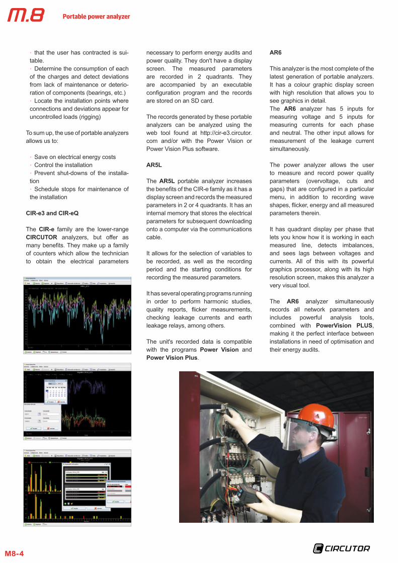
CIR-e3 and CIR-eQ
The CIR-e family are the lower-range CIRCUTOR analyzers, but offer as many benefits. They make up a family of counters which allow the technician to obtain the electrical parameters
necessary to perform energy audits and power quality. They don't have a display screen. The measured parameters are recorded in 2 quadrants. They are accompanied by an executable configuration program and the records are stored on an SD card.
The records generated by these portable analyzers can be analyzed using the web tool found at http://cir-e3.circutor.com and/or with the Power Vision or Power Vision Plus software.
AR5L
The AR5L portable analyzer increases the benefits of the CIR-e family as it has a display screen and records the measured parameters in 2 or 4 quadrants. It has an internal memory that stores the electrical parameters for subsequent downloading onto a computer via the communications cable.
It allows for the selection of variables to be recorded, as well as the recording period and the starting conditions for recording the measured parameters.
It has several operating programs running in order to perform harmonic studies, quality reports, flicker measurements, checking leakage currents and earth leakage relays, among others.
The unit's recorded data is compatible with the programs Power Vision and Power Vision Plus.
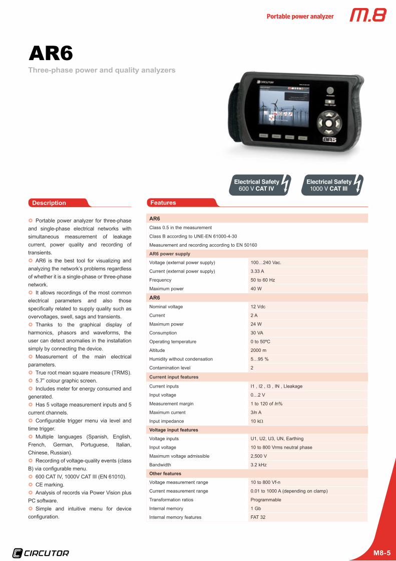
AR6
This analyzer is the most complete of the latest generation of portable analyzers. It has a colour graphic display screen with high resolution that allows you to see graphics in detail.The AR6 analyzer has 5 inputs for measuring voltage and 5 inputs for measuring currents for each phase and neutral. The other input allows for measurement of the leakage current simultaneously.
The power analyzer allows the user to measure and record power quality parameters (overvoltage, cuts and gaps) that are configured in a particular menu, in addition to recording wave shapes, flicker, energy and all measured parameters therein.
It has quadrant display per phase that lets you know how it is working in each measured line, detects imbalances, and sees lags between voltages and currents. All of this with its powerful graphics processor, along with its high resolution screen, makes this analyzer a very visual tool.
The AR6 analyzer simultaneously records all network parameters and includes powerful analysis tools, combined with PowerVision PLUS, making it the perfect interface between installations in need of optimisation and their energy audits.
Portable power analyzer
M8-5
AR6Class 0.5 in the measurement
Class B according to UNE-EN 61000-4-30
Measurement and recording according to EN 50160
AR6 power supply
Voltage (external power supply) 100…240 Vac.
Current (external power supply) 3.33 A
Frequency 50 to 60 Hz
Maximum power 40 W
AR6Nominal voltage 12 Vdc
Current 2 A
Maximum power 24 W
Consumption 30 VA
Operating temperature 0 to 50ºC
Altitude 2000 m
Humidity without condensation 5…95 %
Contamination level 2
Current input features
Current inputs I1 , I2 , I3 , IN , Lleakage
Input voltage 0…2 V
Measurement margin 1 to 120 of In%
Maximum current 3In A
Input impedance 10 kΩ
Voltage input features
Voltage inputs U1, U2, U3, UN, Earthing
Input voltage 10 to 800 Vrms neutral phase
Maximum voltage admissible 2,500 V
Bandwidth 3.2 kHz
Other features
Voltage measurement range 10 to 800 Vf-n
Current measurement range 0.01 to 1000 A (depending on clamp)
Transformation ratios Programmable
Internal memory 1 Gb
Internal memory features FAT 32
Features
x} Portable power analyzer for three-phase and single-phase electrical networks with simultaneous measurement of leakage current, power quality and recording of transients.x} AR6 is the best tool for visualizing and
analyzing the network’s problems regardless of whether it is a single-phase or three-phase network. x} It allows recordings of the most common
electrical parameters and also those specifically related to supply quality such as overvoltages, swell, sags and transients.x} Thanks to the graphical display of
harmonics, phasors and waveforms, the user can detect anomalies in the installation simply by connecting the device.x} Measurement of the main electrical
parameters.x} True root mean square measure (TRMS).x} 5.7” colour graphic screen.x} Includes meter for energy consumed and
generated.x} Has 5 voltage measurement inputs and 5
current channels.x} Configurable trigger menu via level and
time trigger.x} Multiple languages (Spanish, English,
French, German, Portuguese, Italian, Chinese, Russian).x} Recording of voltage-quality events (class
B) via configurable menu.x} 600 CAT IV, 1000V CAT III (EN 61010).x} CE marking.x} Analysis of records via Power Vision plus
PC software.x} Simple and intuitive menu for device
configuration.
Description
AR6Three-phase power and quality analyzers
Portable power analyzer
M8-6
Features
Accuracy class
Voltage 0.5% ± 2 digits
Current 0.5% ± 2 digits
Active power 0.5% ± 2 digits
Reactive power 1% ± 2 digits
Build features
Enclosure Double insulation
Keyboard Movement and function keys
Screen 5.7“ colour VGA
Dimensions 283 x 168 x 80 mm
Weight 1.640 kg
Communications USB
Safety Category III - 600 V, in accordance with 61010
1000 V CAT III/600 V CAT IV for altitudes lower than 2000 m
1000 V CAT III/600 V CAT III/300 V CAT IV above 2000 mStandards
EN 61000-6-4 (2002), Industrial emissions. EN 55011 (1994), Driven (EN 52022 – Class B) EN 55011 (1994), Radiated (EN 55022 – Class A)
EN 61000-6-2 (2022), Industrial immunity EN 61000-4-2 (1995), Electrostatic discharge EN 61000-4-8 (1995), Rapid transient bursts
EN 61000-6-1 (2002), Domestic immunity EN 61000-4-11 (1994), Power supply outages
(*) Accuracy is given by the following measurement conditions: Exclusion of errors produced by the clamps and external voltage transformers, with a temperature range of 5 to 45ºC and power factor 0 to 1
x} List of detected disturbances in tables. x} Display of wave shapes of transients
recorded.x} Manual or programmed PHOTO captures
(wave shapes of 9 channels along with instantaneous values).x} Compatible with AR5-L pins.x} Automatic detection of clamps.x} Memory download via USB connection.x} Graphic display of phasors, harmonics
and wave shapes.
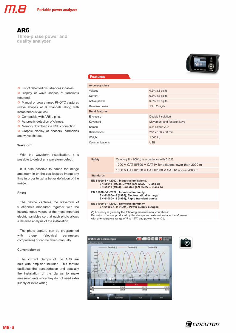
Waveform
xx With the waveform visualization, it is possible to detect any waveform defect.
xx It is also possible to pause the image and zoom-in on the oscilloscope image any time in order to get a better definition of the image.
Photo
xx The device captures the waveform of 9 channels measured together with the instantaneous values of the most important electric variables so that each photo allows a detailed analysis of the installation.
xx The photo capture can be programmed with trigger (electrical parameters comparison) or can be taken manually.
Current clamps
xx The current clamps of the AR6 are built with amplifier included. This feature facilitates the transportation and specially the installation of the clamps to make measurements since they do not need extra supply or extra wiring
Three-phase power and quality analyzer
AR6
Portable power analyzer
M8-7
Display
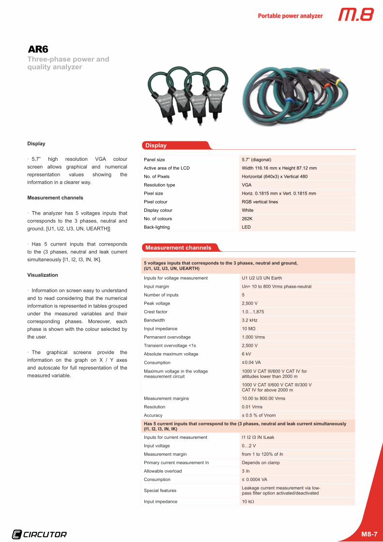
xx 5,7” high resolution VGA colour screen allows graphical and numerical representation values showing the information in a clearer way.
Measurement channels
xx The analyzer has 5 voltages inputs that corresponds to the 3 phases, neutral and ground, [U1, U2, U3, UN, UEARTH]]
xx Has 5 current inputs that corresponds to the (3 phases, neutral and leak current simultaneously [I1, I2, I3, IN, IK].
Visualization
xx Information on screen easy to understand and to read considering that the numerical information is represented in tables grouped under the measured variables and their corresponding phases. Moreover, each phase is shown with the colour selected by the user.
xx The graphical screens provide the information on the graph on X / Y axes and autoscale for full representation of the measured variable.
Display
Panel size 5.7” (diagonal)
Active area of the LCD Width 116.16 mm x Height 87.12 mm
No. of Pixels Horizontal (640x3) x Vertical 480
Resolution type VGA
Pixel size Horiz. 0.1815 mm x Vert. 0.1815 mm
Pixel colour RGB vertical lines
Display colour White
No. of colours 262K
Back-lighting LED
Measurement channels
5 voltages inputs that corresponds to the 3 phases, neutral and ground, (U1, U2, U3, UN, UEARTH)
Inputs for voltage measurement U1 U2 U3 UN Earth
Input margin Un= 10 to 800 Vrms phase-neutral
Number of inputs 5
Peak voltage 2,500 V
Crest factor 1.0…1,875
Bandwidth 3.2 kHz
Input impedance 10 MΩ
Permanent overvoltage 1.000 Vrms
Transient overvoltage <1s 2,500 V
Absolute maximum voltage 6 kV
Consumption ≤ 0.04 VA
Maximum voltage in the voltage measurement circuit
1000 V CAT III/600 V CAT IV for altitudes lower than 2000 m
1000 V CAT II/600 V CAT III/300 V CAT IV for above 2000 m
Measurement margins 10.00 to 800.00 Vrms
Resolution 0.01 Vrms
Accuracy ± 0.5 % of Vnom
Has 5 current inputs that correspond to the (3 phases, neutral and leak current simultaneously (I1, I2, I3, IN, IK)
Inputs for current measurement I1 I2 I3 IN ILeak
Input voltage 0…2 V
Measurement margin from 1 to 120% of In
Primary current measurement In Depends on clamp
Allowable overload 3 In
Consumption ≤ 0.0004 VA
Special features Leakage current measurement via low-pass filter option activated/deactivated
Input impedance 10 kΩ
Three-phase power and quality analyzer
AR6
Portable power analyzer
M8-8
Three-phase power and quality analyzer
AR6
Easy configuration men
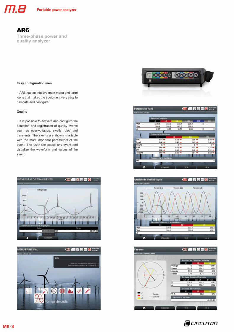
xx AR6 has an intuitive main menu and large icons that makes the equipment very easy to navigate and configure.
Quality
xx It is possible to activate and configure the detection and registration of quality events such as over-voltages, swells, dips and transients. The events are shown in a table with the most important parameters of the event. The user can select any event and visualize the waveform and values of the event.
Portable power analyzer
M8-9
Three-phase power and quality analyzer
AR6
Battery NiMH (Nickel Metal Hydride)
Voltage 6 V
Capacity 4,200 mAh
Charge time 2 …2,5 h
Battery life while in use 4hrs with LCD on
8hrs with LCD off
Memory
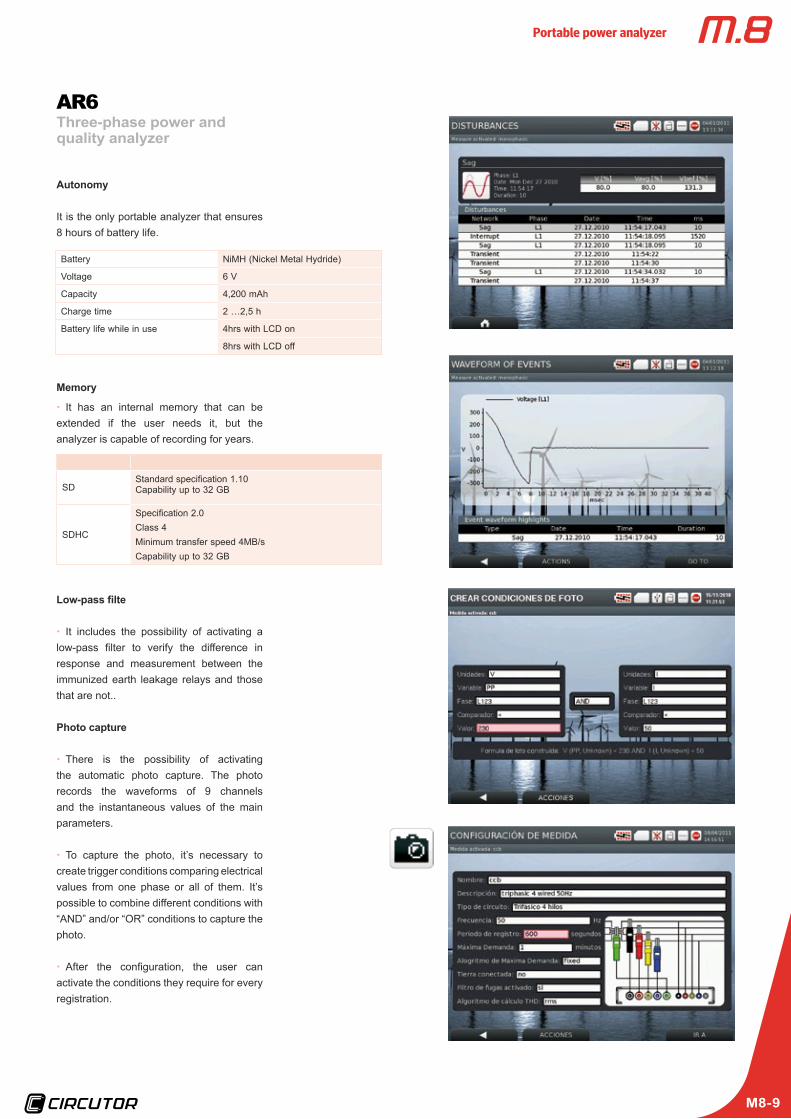
xx It has an internal memory that can be extended if the user needs it, but the analyzer is capable of recording for years.
SDStandard specification 1.10Capability up to 32 GB
SDHC
Specification 2.0Class 4Minimum transfer speed 4MB/sCapability up to 32 GB
Low-pass filte
xx It includes the possibility of activating a low-pass filter to verify the difference in response and measurement between the immunized earth leakage relays and those that are not..
Photo capture
xx There is the possibility of activating the automatic photo capture. The photo records the waveforms of 9 channels and the instantaneous values of the main parameters.
xx To capture the photo, it’s necessary to create trigger conditions comparing electrical values from one phase or all of them. It’s possible to combine different conditions with “AND” and/or “OR” conditions to capture the photo.
xx After the configuration, the user can activate the conditions they require for every registration.
Autonomy
It is the only portable analyzer that ensures 8 hours of battery life.
Portable power analyzer
M8-10
Three-phase power and quality analyzer
Customizable and configurabl
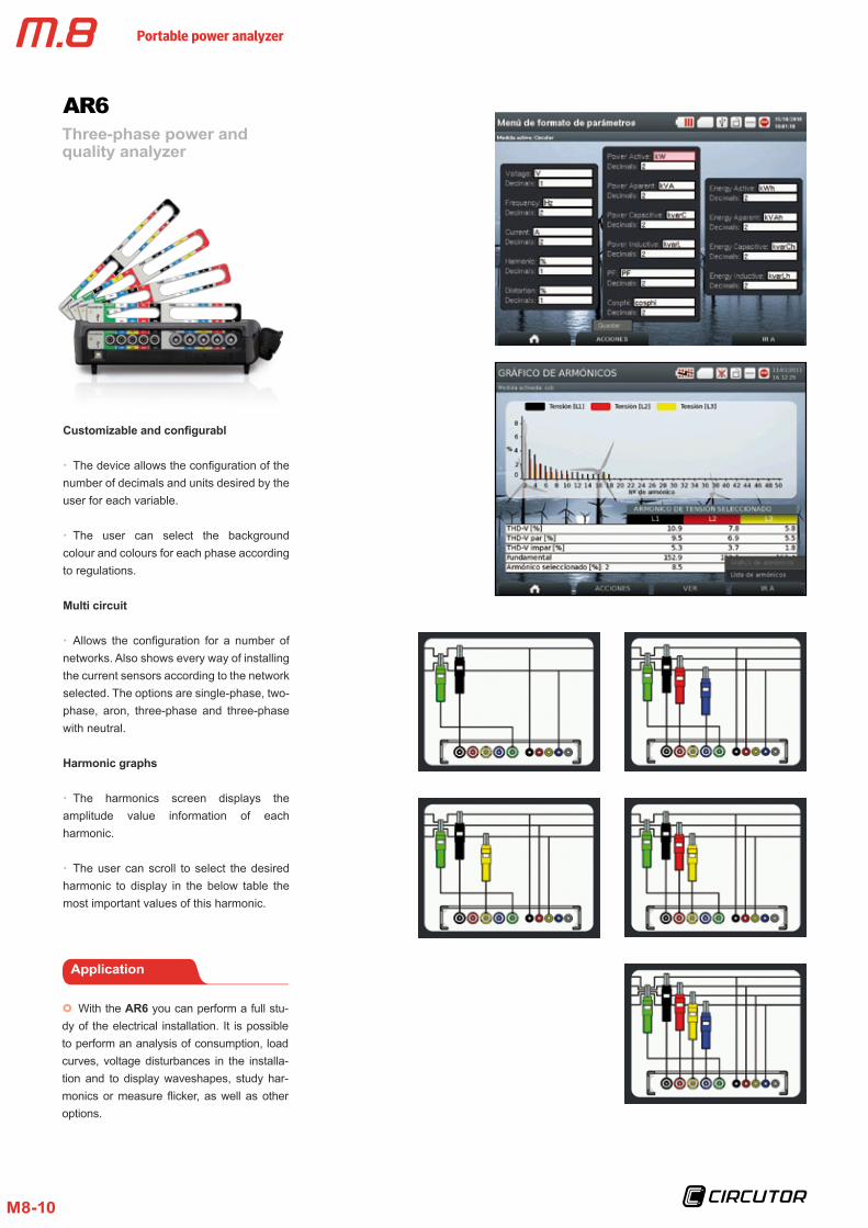
xx The device allows the configuration of the number of decimals and units desired by the user for each variable.
xx The user can select the background colour and colours for each phase according to regulations.
Multi circuit
xx Allows the configuration for a number of networks. Also shows every way of installing the current sensors according to the network selected. The options are single-phase, two-phase, aron, three-phase and three-phase with neutral.
Harmonic graphs
xx The harmonics screen displays the amplitude value information of each harmonic.
xx The user can scroll to select the desired harmonic to display in the below table the most important values of this harmonic.
AR6
Application
x} With the AR6 you can perform a full stu-dy of the electrical installation. It is possible to perform an analysis of consumption, load curves, voltage disturbances in the installa-tion and to display waveshapes, study har-monics or measure flicker, as well as other options.
Portable power analyzer
M8-11
Three-phase power and quality analyzer
AR6
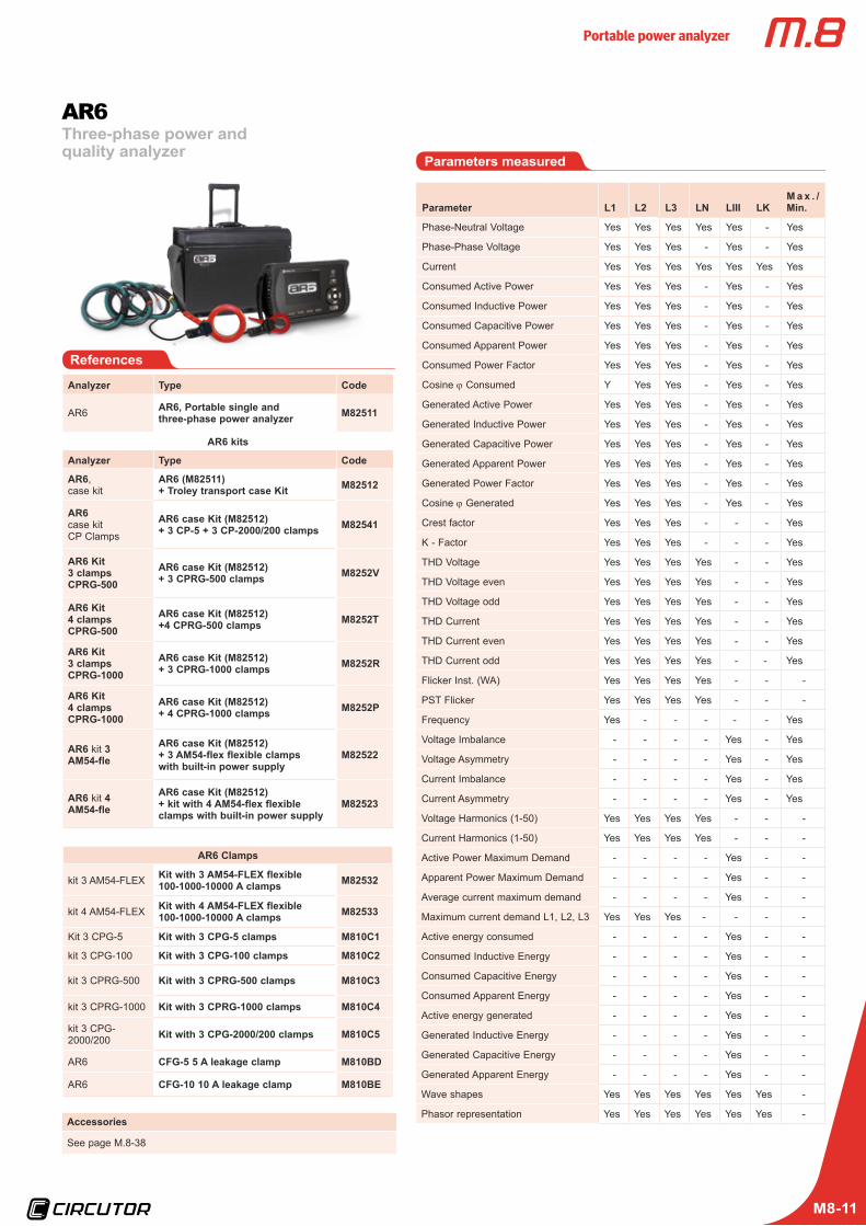
Analyzer Type Code
AR6 AR6, Portable single andthree-phase power analyzer M82511
AR6 kits
Analyzer Type Code
AR6, case kit
AR6 (M82511) + Troley transport case Kit M82512
AR6case kitCP Clamps
AR6 case Kit (M82512)+ 3 CP-5 + 3 CP-2000/200 clamps M82541
AR6 Kit 3 clamps CPRG-500
AR6 case Kit (M82512)+ 3 CPRG-500 clamps M8252V
AR6 Kit 4 clamps CPRG-500
AR6 case Kit (M82512)+4 CPRG-500 clamps M8252T
AR6 Kit 3 clamps CPRG-1000
AR6 case Kit (M82512)+ 3 CPRG-1000 clamps M8252R
AR6 Kit 4 clamps CPRG-1000
AR6 case Kit (M82512)+ 4 CPRG-1000 clamps M8252P
AR6 kit 3 AM54-fle
AR6 case Kit (M82512)+ 3 AM54-flex flexible clamps with built-in power supply
M82522
AR6 kit 4 AM54-fle
AR6 case Kit (M82512)+ kit with 4 AM54-flex flexibleclamps with built-in power supply
M82523
AR6 Clamps
kit 3 AM54-FLEX Kit with 3 AM54-FLEX flexible100-1000-10000 A clamps M82532
kit 4 AM54-FLEX Kit with 4 AM54-FLEX flexible100-1000-10000 A clamps M82533
Kit 3 CPG-5 Kit with 3 CPG-5 clamps M810C1
kit 3 CPG-100 Kit with 3 CPG-100 clamps M810C2
kit 3 CPRG-500 Kit with 3 CPRG-500 clamps M810C3
kit 3 CPRG-1000 Kit with 3 CPRG-1000 clamps M810C4
kit 3 CPG-2000/200 Kit with 3 CPG-2000/200 clamps M810C5
AR6 CFG-5 5 A leakage clamp M810BD
AR6 CFG-10 10 A leakage clamp M810BE
References
Accessories
See page M.8-38
Parameter L1 L2 L3 LN LIII LKM a x . /Min.
Phase-Neutral Voltage Yes Yes Yes Yes Yes - Yes
Phase-Phase Voltage Yes Yes Yes - Yes - Yes
Current Yes Yes Yes Yes Yes Yes Yes
Consumed Active Power Yes Yes Yes - Yes - Yes
Consumed Inductive Power Yes Yes Yes - Yes - Yes
Consumed Capacitive Power Yes Yes Yes - Yes - Yes
Consumed Apparent Power Yes Yes Yes - Yes - Yes
Consumed Power Factor Yes Yes Yes - Yes - Yes
Cosine j Consumed Y Yes Yes - Yes - Yes
Generated Active Power Yes Yes Yes - Yes - Yes
Generated Inductive Power Yes Yes Yes - Yes - Yes
Generated Capacitive Power Yes Yes Yes - Yes - Yes
Generated Apparent Power Yes Yes Yes - Yes - Yes
Generated Power Factor Yes Yes Yes - Yes - Yes
Cosine j Generated Yes Yes Yes - Yes - Yes
Crest factor Yes Yes Yes - - - Yes
K - Factor Yes Yes Yes - - - Yes
THD Voltage Yes Yes Yes Yes - - Yes
THD Voltage even Yes Yes Yes Yes - - Yes
THD Voltage odd Yes Yes Yes Yes - - Yes
THD Current Yes Yes Yes Yes - - Yes
THD Current even Yes Yes Yes Yes - - Yes
THD Current odd Yes Yes Yes Yes - - Yes
Flicker Inst. (WA) Yes Yes Yes Yes - - -
PST Flicker Yes Yes Yes Yes - - -
Frequency Yes - - - - - Yes
Voltage Imbalance - - - - Yes - Yes
Voltage Asymmetry - - - - Yes - Yes
Current Imbalance - - - - Yes - Yes
Current Asymmetry - - - - Yes - Yes
Voltage Harmonics (1-50) Yes Yes Yes Yes - - -
Current Harmonics (1-50) Yes Yes Yes Yes - - -
Active Power Maximum Demand - - - - Yes - -
Apparent Power Maximum Demand - - - - Yes - -
Average current maximum demand - - - - Yes - -
Maximum current demand L1, L2, L3 Yes Yes Yes - - - -
Active energy consumed - - - - Yes - -
Consumed Inductive Energy - - - - Yes - -
Consumed Capacitive Energy - - - - Yes - -
Consumed Apparent Energy - - - - Yes - -
Active energy generated - - - - Yes - -
Generated Inductive Energy - - - - Yes - -
Generated Capacitive Energy - - - - Yes - -
Generated Apparent Energy - - - - Yes - -
Wave shapes Yes Yes Yes Yes Yes Yes -
Phasor representation Yes Yes Yes Yes Yes Yes -
Parameters measured
Portable power analyzer
M8-12
Three-phase power and quality analyzer
AR6
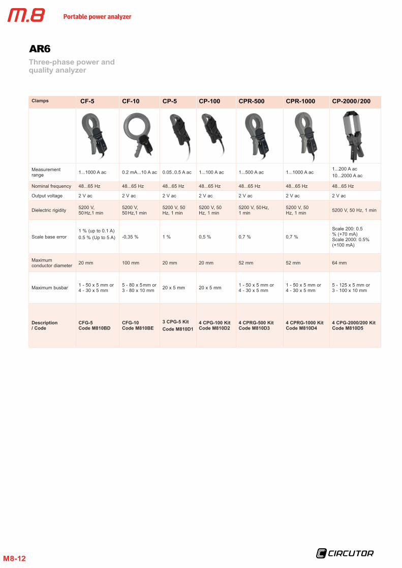
Clamps CF-5 CF-10 CP-5 CP-100 CPR-500 CPR-1000 CP-2000 / 200
Measurement range 1...1000 A ac 0.2 mA...10 A ac 0.05..0.5 A ac 1...100 A ac 1...500 A ac 1...1000 A ac
1...200 A ac10...2000 A ac
Nominal frequency 48...65 Hz 48...65 Hz 48...65 Hz 48...65 Hz 48...65 Hz 48...65 Hz 48...65 Hz
Output voltage 2 V ac 2 V ac 2 V ac 2 V ac 2 V ac 2 V ac 2 V ac
Dielectric rigidity 5200 V, 50 Hz,1 min
5200 V, 50 Hz,1 min
5200 V, 50 Hz, 1 min
5200 V, 50 Hz, 1 min
5200 V, 50 Hz, 1 min
5200 V, 50 Hz, 1 min 5200 V, 50 Hz, 1 min
Scale base error1 % (up to 0.1 A)0.5 % (Up to 5 A) -0,35 % 1 % 0,5 % 0,7 % 0,7 %
Scale 200: 0.5 % (+70 mA)Scale 2000: 0.5% (+100 mA)
Maximum conductor diameter 20 mm 100 mm 20 mm 20 mm 52 mm 52 mm 64 mm
Maximum busbar 1 - 50 x 5 mm or 4 - 30 x 5 mm
5 - 80 x 5 mm or 3 - 80 x 10 mm 20 x 5 mm 20 x 5 mm 1 - 50 x 5 mm or
4 - 30 x 5 mm1 - 50 x 5 mm or 4 - 30 x 5 mm
5 - 125 x 5 mm or 3 - 100 x 10 mm
Description / Code
CFG-5 Code M810BD
CFG-10Code M810BE
3 CPG-5 Kit Code M810D1
4 CPG-100 Kit Code M810D2
4 CPRG-500 Kit Code M810D3
4 CPRG-1000 Kit Code M810D4
4 CPG-2000/200 Kit Code M810D5
Portable power analyzer
M8-13
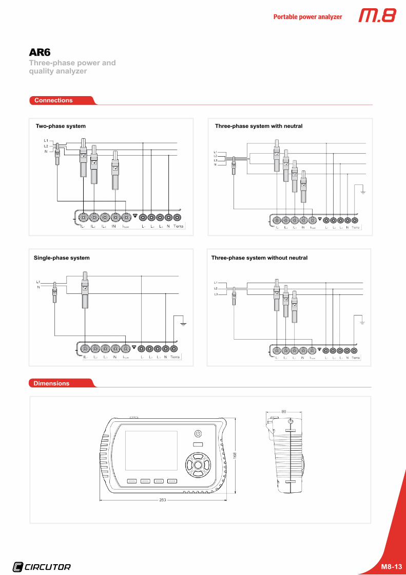
Connections
Single-phase system
Two-phase system Three-phase system with neutral
Three-phase system without neutral
Dimensions
Three-phase power and quality analyzer
AR6
Portable power analyzer
M8-14
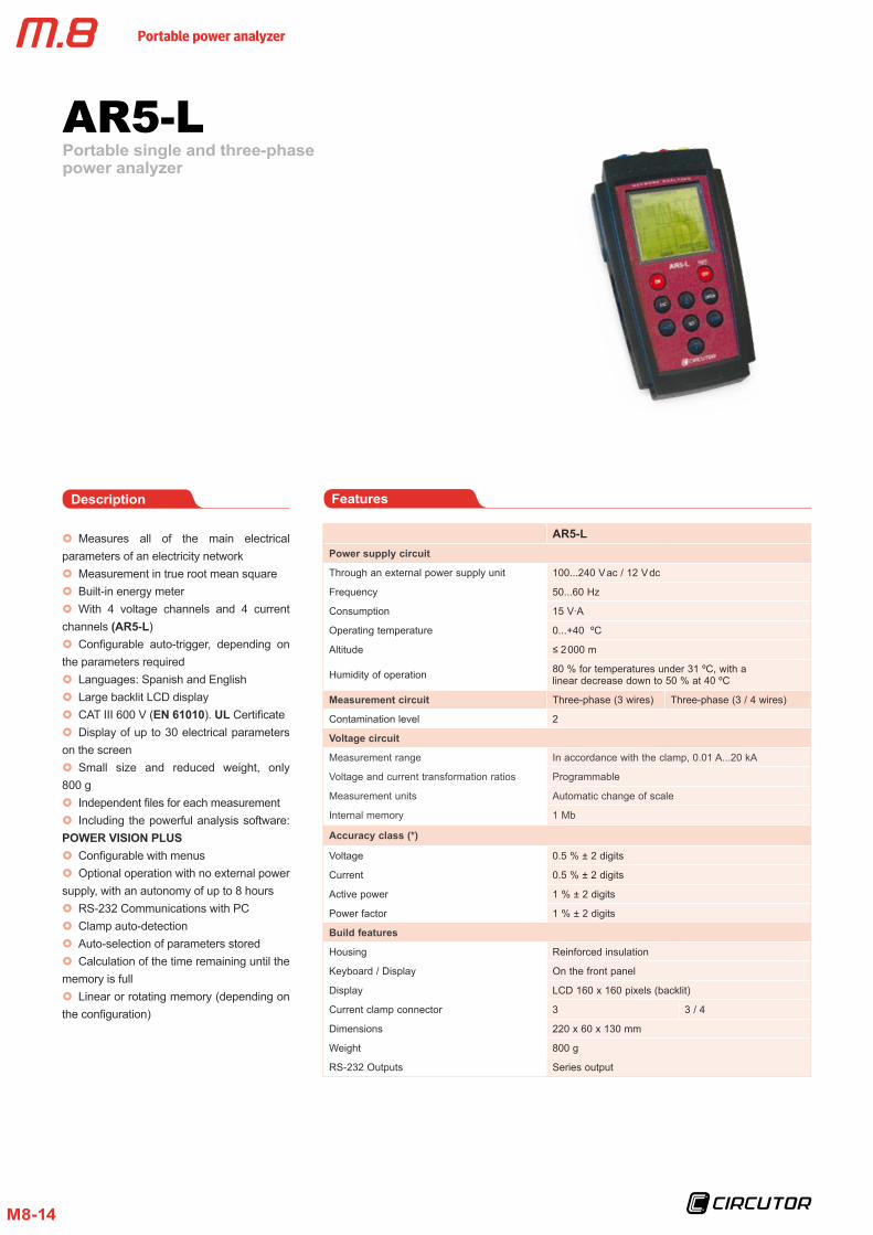
Portable single and three-phase power analyzer
AR5-L
AR5-LPower supply circuit
Through an external power supply unit 100...240 V ac / 12 V dc
Frequency 50...60 Hz
Consumption 15 V ·A
Operating temperature 0...+40 ºC
Altitude ≤ 2 000 m
Humidity of operation 80 % for temperatures under 31 ºC, with a linear decrease down to 50 % at 40 ºC
Measurement circuit Three-phase (3 wires) Three-phase (3 / 4 wires)
Contamination level 2
Voltage circuit
Measurement range In accordance with the clamp, 0.01 A...20 kA
Voltage and current transformation ratios Programmable
Measurement units Automatic change of scale
Internal memory 1 Mb
Accuracy class (*)
Voltage 0.5 % ± 2 digits
Current 0.5 % ± 2 digits
Active power 1 % ± 2 digits
Power factor 1 % ± 2 digits
x} Measures all of the main electrical parameters of an electricity networkx} Measurement in true root mean squarex} Built-in energy meter x} With 4 voltage channels and 4 current
channels (AR5-L)x} Configurable auto-trigger, depending on
the parameters requiredx} Languages: Spanish and Englishx} Large backlit LCD displayx} CAT III 600 V (EN 61010). UL Certificatex} Display of up to 30 electrical parameters
on the screenx} Small size and reduced weight, only
800 gx} Independent files for each measurementx} Including the powerful analysis software:
POWER VISION PLUSx} Configurable with menusx} Optional operation with no external power
supply, with an autonomy of up to 8 hoursx} RS-232 Communications with PCx} Clamp auto-detectionx} Auto-selection of parameters storedx} Calculation of the time remaining until the
memory is fullx} Linear or rotating memory (depending on
the configuration)
FeaturesDescription
Build features
Housing Reinforced insulation
Keyboard / Display On the front panel
Display LCD 160 x 160 pixels (backlit)
Current clamp connector 3 3 / 4
Dimensions 220 x 60 x 130 mm
Weight 800 g
RS-232 Outputs Series output
Portable power analyzer
M8-15
Portable single and three-phase power analyzer
AR5-L
AR5-LSafety Category III - 600 V, in accordance with 61010
Standards
EN 61000-3-2 (1995), Harmonics
EN 61000-3-3 (1995), Voltage fluctuati ns
EN 61000-6-4 (2002), Industrial emissionsEN 55011 (1994), Driven (EN 52022 – Class B) EN 55011 (1994), Radiated (EN 55022 – Class A)
EN 61000-6-2 (2022), Industrial immunityEN 61000-4-2 (1995), Electrostatic discharge ENV 50140 (1993), Radiated electromagnetic field EN 61000-4-8 (1995), Rapid transient bursts ENV 50141 (1993), RF in common mode EN 61000-4-8 (1995), Magnetic field at 50 Hz
EN 61000-6-1 (2002), Domestic immunityEN 61000-4-5 (1995), Shockwave EN 61000-4-11 (1994), Power supply interruptions
(*) Accuracy is given by the following measurement conditions: Exclusion of errors produced by the clamps and external voltage transformers, with a range of temperature of 5 ... 45 ºC and power factor of 0 ... 1
Application
x} Complete study of the installation where the analyzer is capable of gathering different types of records: harmonics, disturbances, meter verification, transients, flicker, etc.
Features
Analyzer Clamps Program Transport Type Code
Units
AR5-L - Energy / Harmonics Carrying Bag AR5-L- Power analyzer with 4 current inputs M80111
AR5-L Kits
AR5-L 3 x CPR-10001 x CPR-500 Energy / Harmonics Carrying Bag 3 L AR5-L M80811
AR5-L 3 x CPR-2000/2001 x CPR-1000 Energy / Harmonics Carrying Bag 4 L AR5-L M80821
AR5-L3 x CPR-2000/2001 x CPR-10003 x CP-5
Energy / Harmonics and Disturbances Carrying Bag 5 L AR5-L M80832
AR5-L 3 x C-FLEX–45 cm1 x CF-5
Energy / Harmonics and Disturbances Carrying Bag 11 L AR5-L-RBT M80843
AR5-L 3 x C-FLEX-80 cm1 x CF-5
Energy / Harmonics and Disturbances Carrying Bag 12 L AR5-L-RBT M80853
AR5-L 3 x C-FLEX-45 cm1 x CF-5
Energy / Harmonics and Disturbances Case 11 LM AR5-L-RBT M80643
AR5-L 3 x C-FLEX-80 cm1 x CF-5
Energy / Harmonics and Disturbances Case 12 LM AR5-L-RBT M80653
The two analyzers include: 3 voltage cables + power supply
All kits include: 3 voltage cables + power supply + PowerVision software + energy / harmonics program + 3 clamps
References
Accessories
See page M.8-40
Portable power analyzer
M8-16
ParameterSymbol (unit) L1 L2 L3
Three-phase value
phase-neutral voltage V Yes Yes Yes -
Current A Yes Yes Yes Yes
Neutral current (only AR5-L) IN Yes
Frequency Hz Yes - - -
Active power kW Yes Yes Yes Yes
Power factor L kvarL Yes Yes Yes Yes
Power factor C kvarC Yes Yes Yes Yes
Apparent power kVA - - - Yes
Power factor PF Yes Yes Yes Yes
Active energy kW ·h Yes Yes Yes Yes
Power factor L kvar ·h L Yes Yes Yes Yes
Power factor C kvar ·h C Yes Yes Yes Yes
Voltage harmonics Yes Yes Yes -
Current harmonics Yes Yes Yes -
Current harmonics on neutral Yes
Parameters measured
Three-phase system, 4 wires
Portable single and three-phase power analyzer
AR5-L
ParameterSymbol (unit) L1-L2 L2-L3 L3-L1
Three-phase value
phase-phase voltage V Yes Yes Yes -
Current A Yes Yes Yes Yes
Frequency Hz Yes - - -
Active power kW Yes Yes Yes Yes
Power factor L kvarL Yes Yes Yes Yes
Power factor C kvarC Yes Yes Yes Yes
Apparent power kVA - - - Yes
Power factor PF Yes Yes Yes Yes
Active energy kW ·h - - - Yes
Power factor L kvar ·h L - - - Yes
Power factor C kvar ·h C - - - Yes
Voltage harmonics Yes Yes Yes -
Current harmonics Yes Yes Yes -
Three-phase system, 3 wires
ParameterSymbol (unit) L1-N L2-N
Two-phase value L1 - L2
phase-phase voltage V Yes Yes Yes
Current A Yes Yes Yes
Neutral current (only AR5-L) IN -
Frequency Hz Yes - -
Active power kW Yes Yes Yes
Power factor L kvar L Yes Yes Yes
Power factor C kvar C Yes Yes Yes
Apparent power kVA - - Yes
Power factor PF Yes Yes Yes
Active energy kW ·h - - Yes
Power factor L kvar ·h L - - Yes
Power factor C kvar ·h C - - Yes
Voltage harmonics Yes Yes -
Current harmonics Yes Yes -
Current harmonics on neutral Yes
Two-phase System
ParameterSymbol (unit) L1-N
phase-phase voltage V Yes
Current A Yes
Frequency Hz Yes
Active power kW Yes
Power factor L kvarL Yes
Power factor C kvarL / (-C) Yes
Apparent power kVA Yes
Power factor PF Yes
Active energy kW ·h Yes
Power factor L kvar ·h L Yes
Power factor C kvar ·h C Yes
Voltage harmonics Yes
Current harmonics Yes
Single-phase system
Portable power analyzer
M8-17
Portable single and three-phase power analyzer
AR5-L
Description Equipment Type Code
Updating harmonics AR5-L Updating ARI M80221
Flicker (PST and PLT assessment) AR5-L FL Program M80223
Detection of network disturbances AR5-L PERTURB Program M80224
CHECK METER, meter verification system AR5-L CM Program M80225
Optic fibre sensor, shunts and CHECK METER program included AR5-L Optical check meter kit M806B3
FAST CHECK, motor start-up AR5-L Fast Program M80226
LEAK METER, detection and analysis of leakages AR5-L Leak Program M80229
FILE VISION, display of files in AR5-L AR5-L Fil Vision Program M8022A
Programs
Memory capacity example: In the Energy program, if you record 30 network parameters, with a registration period of 15 minutes, you obtain an autonomy of 80 days of memory.
Programs
Harmonics
Type Code
Updating ARI M80221
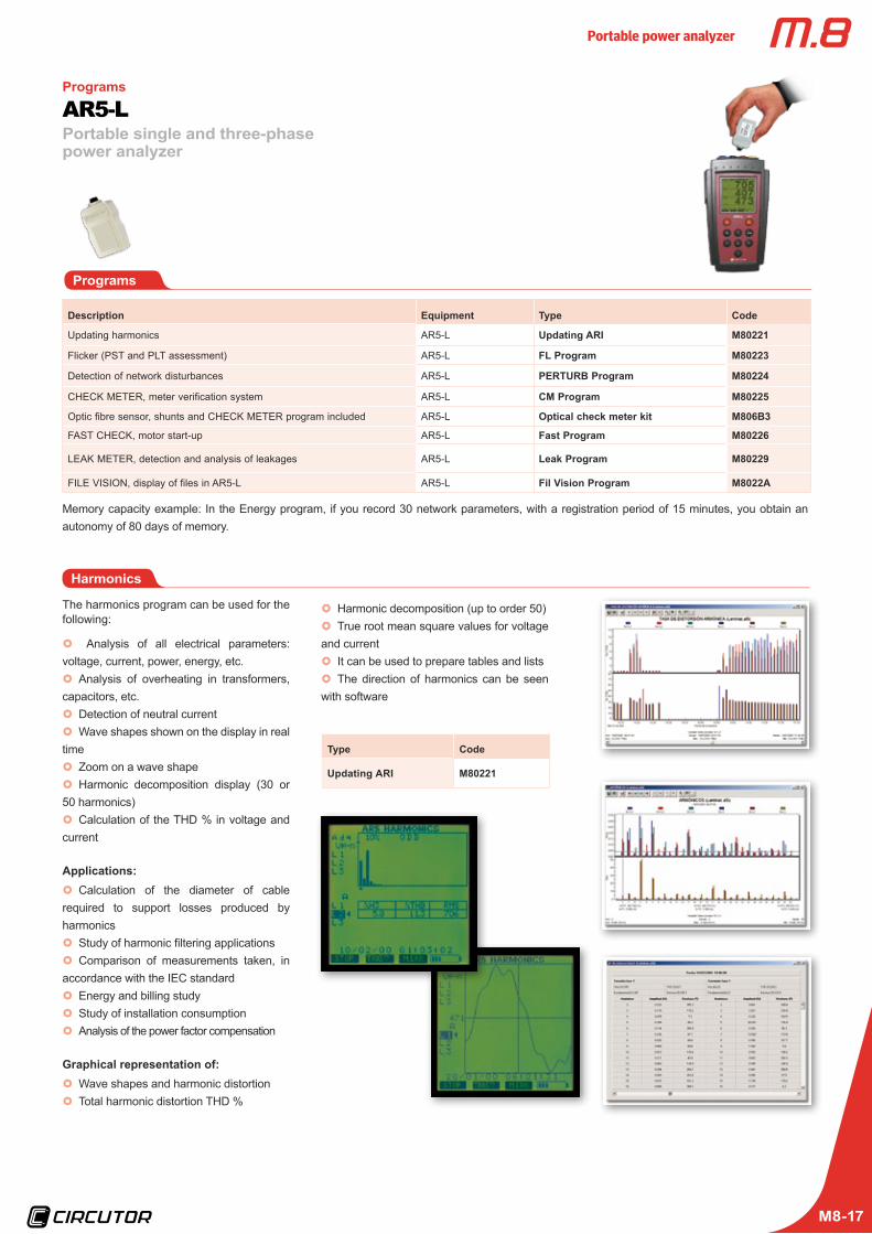
The harmonics program can be used for the following:
x} Analysis of all electrical parameters: voltage, current, power, energy, etc.x} Analysis of overheating in transformers,
capacitors, etc.x} Detection of neutral currentx} Wave shapes shown on the display in real
time x} Zoom on a wave shapex} Harmonic decomposition display (30 or
50 harmonics)x} Calculation of the THD % in voltage and
current
Applications:x} Calculation of the diameter of cable
required to support losses produced by harmonicsx} Study of harmonic filtering applicationsx} Comparison of measurements taken, in
accordance with the IEC standardx} Energy and billing studyx} Study of installation consumptionx} Analysis of the power factor compensation
Graphical representation of:x} Wave shapes and harmonic distortionx} Total harmonic distortion THD %
x} Harmonic decomposition (up to order 50)x} True root mean square values for voltage
and currentx} It can be used to prepare tables and listsx} The direction of harmonics can be seen
with software
Portable power analyzer
M8-18
Network quality - Disturbances
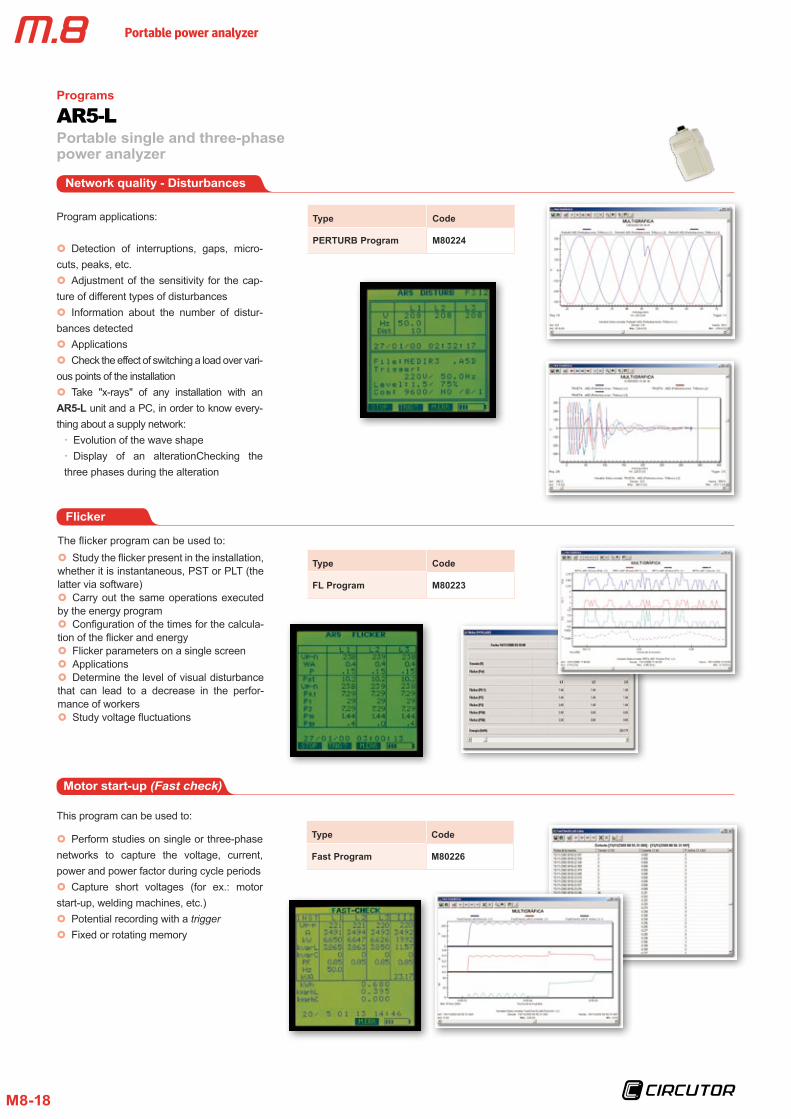
Program applications:
x} Detection of interruptions, gaps, micro-cuts, peaks, etc.x} Adjustment of the sensitivity for the cap-
ture of different types of disturbancesx} Information about the number of distur-
bances detectedx} Applicationsx} Check the effect of switching a load over vari-
ous points of the installationx} Take "x-rays" of any installation with an
AR5-L unit and a PC, in order to know every-thing about a supply network:xx Evolution of the wave shapexx Display of an alterationChecking the
three phases during the alteration
Type Code
PERTURB Program M80224
Flicker
The flicker program can be used to:x} Study the flicker present in the installation,
whether it is instantaneous, PST or PLT (the latter via software)x} Carry out the same operations executed
by the energy programx} Configuration of the times for the calcula-
tion of the flicker and energyx} Flicker parameters on a single screenx} Applicationsx} Determine the level of visual disturbance
that can lead to a decrease in the perfor-mance of workersx} Study voltage fluctuations
Type Code
FL Program M80223
This program can be used to:
x} Perform studies on single or three-phase networks to capture the voltage, current, power and power factor during cycle periodsx} Capture short voltages (for ex.: motor
start-up, welding machines, etc.)x} Potential recording with a trigger x} Fixed or rotating memory
Type Code
Fast Program M80226
Portable single and three-phase power analyzer
AR5-LPrograms
Motor start-up (Fast check)
Portable power analyzer
M8-19
Portable single and three-phase power analyzer
AR5-LPrograms
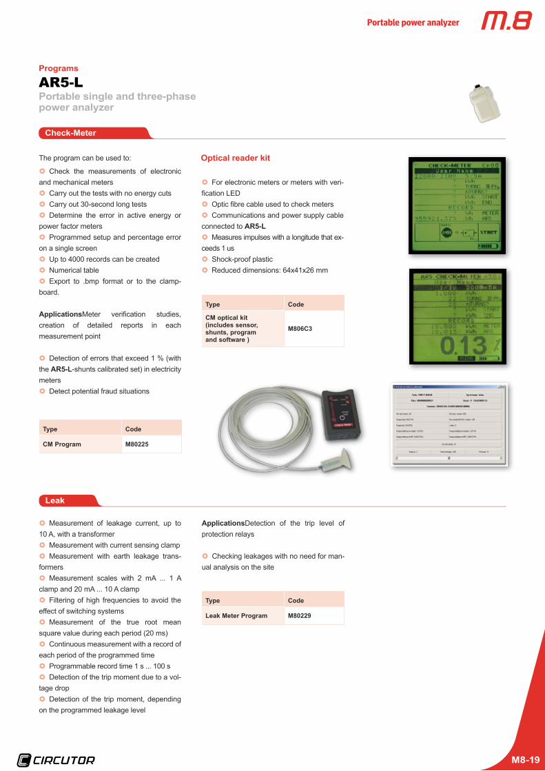
The program can be used to:
x} Check the measurements of electronic and mechanical metersx} Carry out the tests with no energy cutsx} Carry out 30-second long testsx} Determine the error in active energy or
power factor metersx} Programmed setup and percentage error
on a single screenx} Up to 4000 records can be createdx} Numerical table x} Export to .bmp format or to the clamp-
board.
ApplicationsMeter verification studies, creation of detailed reports in each measurement point
x} Detection of errors that exceed 1 % (with the AR5-L-shunts calibrated set) in electricity metersx} Detect potential fraud situations
Type Code
CM Program M80225
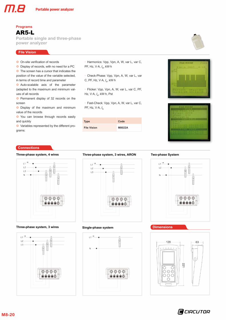
Optical reader kit
x} For electronic meters or meters with veri-fication LEDx} Optic fibre cable used to check metersx} Communications and power supply cable
connected to AR5-Lx} Measures impulses with a longitude that ex-
ceeds 1 usx} Shock-proof plasticx} Reduced dimensions: 64x41x26 mm
Type Code
CM optical kit(includes sensor, shunts, program and software )
M806C3
Leak
x} Measurement of leakage current, up to 10 A, with a transformerx} Measurement with current sensing clampx} Measurement with earth leakage trans-
formersx} Measurement scales with 2 mA ... 1 A
clamp and 20 mA ... 10 A clampx} Filtering of high frequencies to avoid the
effect of switching systemsx} Measurement of the true root mean
square value during each period (20 ms)x} Continuous measurement with a record of
each period of the programmed timex} Programmable record time 1 s ... 100 sx} Detection of the trip moment due to a vol-
tage dropx} Detection of the trip moment, depending
on the programmed leakage level
Type Code
Leak Meter Program M80229
ApplicationsDetection of the trip level of protection relays
x} Checking leakages with no need for man-ual analysis on the site
Check-Meter
Portable power analyzer
M8-20
Portable single and three-phase power analyzer
AR5-LPrograms
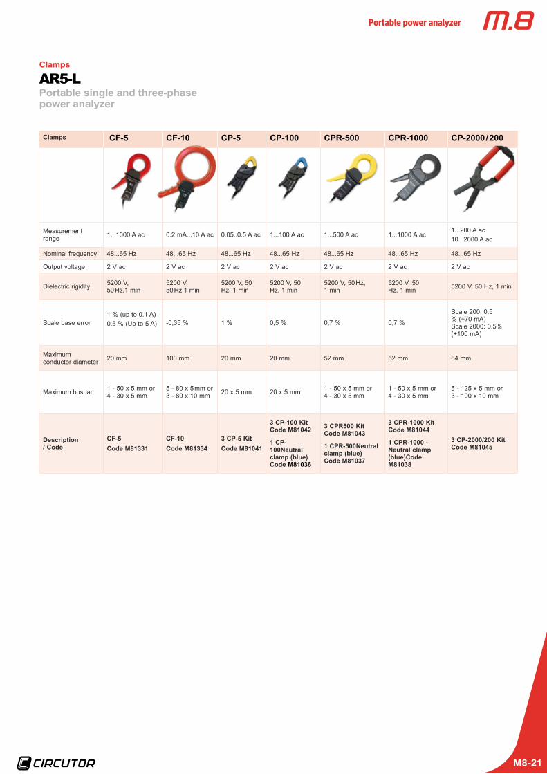
File Vision
Type Code
File Vision M8022A
x} On-site verification of recordsx} Display of records, with no need for a PCx} The screen has a cursor that indicates the
position of the value of the variable selected, in terms of record time and parameterx} Auto-scalable axis of the parameter
(adapted to the maximum and minimum val-ues of all recordsx} Permanent display of 32 records on the
screenx} Display of the maximum and minimum
value of the recordsx} You can browse through records easily
and quicklyx} Variables represented by the different pro-
grams:
xx Harmonics: Vpp, Vpn, A, W, var L, var C, PF, Hz, V ·A, IN, kW ·h
xx Check-Phase: Vpp, Vpn, A, W, var L, var C, PF, Hz, V ·A, IN, kW ·h
xx Flicker: Vpp, Vpn, A, W, var L, var C, PF, Hz, V ·A, IN, kW ·h, Pst
xx Fast-Check: Vpp, Vpn, A, W, var L, var C, PF, Hz, V ·A, IN
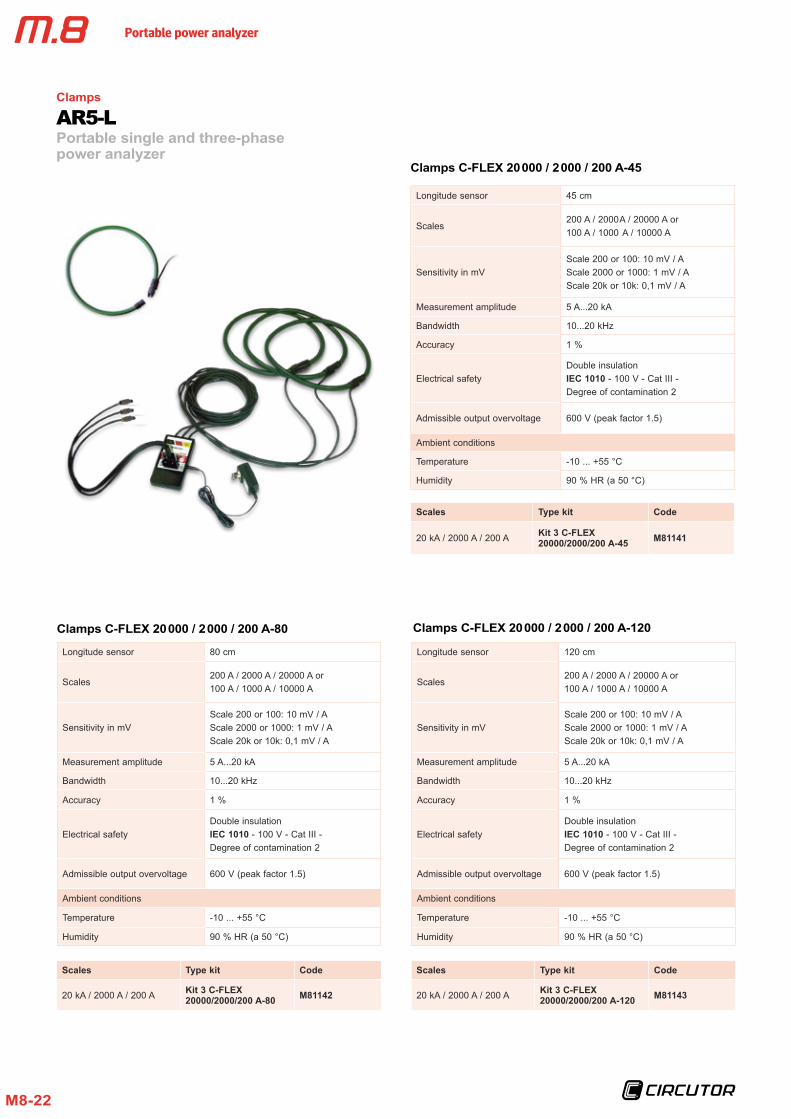
Connections
Three-phase system, 4 wires
Three-phase system, 3 wires Dimensions
Two-phase System
Single-phase system
Three-phase system, 3 wires, ARON
Portable power analyzer
M8-21
Portable single and three-phase power analyzer
AR5-LClamps
Clamps CF-5 CF-10 CP-5 CP-100 CPR-500 CPR-1000 CP-2000 / 200
Measurement range 1...1000 A ac 0.2 mA...10 A ac 0.05..0.5 A ac 1...100 A ac 1...500 A ac 1...1000 A ac
1...200 A ac10...2000 A ac
Nominal frequency 48...65 Hz 48...65 Hz 48...65 Hz 48...65 Hz 48...65 Hz 48...65 Hz 48...65 Hz
Output voltage 2 V ac 2 V ac 2 V ac 2 V ac 2 V ac 2 V ac 2 V ac
Dielectric rigidity 5200 V, 50 Hz,1 min
5200 V, 50 Hz,1 min
5200 V, 50 Hz, 1 min
5200 V, 50 Hz, 1 min
5200 V, 50 Hz, 1 min
5200 V, 50 Hz, 1 min 5200 V, 50 Hz, 1 min
Scale base error1 % (up to 0.1 A)0.5 % (Up to 5 A) -0,35 % 1 % 0,5 % 0,7 % 0,7 %
Scale 200: 0.5 % (+70 mA)Scale 2000: 0.5% (+100 mA)
Maximum conductor diameter 20 mm 100 mm 20 mm 20 mm 52 mm 52 mm 64 mm
Maximum busbar 1 - 50 x 5 mm or 4 - 30 x 5 mm
5 - 80 x 5 mm or 3 - 80 x 10 mm 20 x 5 mm 20 x 5 mm 1 - 50 x 5 mm or
4 - 30 x 5 mm1 - 50 x 5 mm or 4 - 30 x 5 mm
5 - 125 x 5 mm or 3 - 100 x 10 mm
Description / Code
CF-5 Code M81331
CF-10Code M81334
3 CP-5 Kit Code M81041
3 CP-100 Kit Code M81042
1 CP-100Neutral clamp (blue)Code M81036
3 CPR500 Kit Code M81043
1 CPR-500Neutral clamp (blue)Code M81037
3 CPR-1000 Kit Code M81044
1 CPR-1000 - Neutral clamp (blue)Code M81038
3 CP-2000/200 Kit Code M81045
Portable power analyzer
M8-22
Portable single and three-phase power analyzer
AR5-LClamps
Longitude sensor 45 cm
Scales200 A / 2000 A / 20000 A or100 A / 1000 A / 10000 A
Sensitivity in mVScale 200 or 100: 10 mV / AScale 2000 or 1000: 1 mV / AScale 20k or 10k: 0,1 mV / A
Measurement amplitude 5 A...20 kA
Bandwidth 10...20 kHz
Accuracy 1 %
Electrical safetyDouble insulationIEC 1010 - 100 V - Cat III - Degree of contamination 2
Admissible output overvoltage 600 V (peak factor 1.5)
Ambient conditions
Temperature -10 ... +55 °C
Humidity 90 % HR (a 50 °C)
Clamps C-FLEX 20 000 / 2 000 / 200 A-45
Scales Type kit Code
20 kA / 2000 A / 200 A Kit 3 C-FLEX 20000/2000/200 A-45 M81141
Longitude sensor 120 cm
Scales200 A / 2000 A / 20000 A or100 A / 1000 A / 10000 A
Sensitivity in mVScale 200 or 100: 10 mV / AScale 2000 or 1000: 1 mV / AScale 20k or 10k: 0,1 mV / A
Measurement amplitude 5 A...20 kA
Bandwidth 10...20 kHz
Accuracy 1 %
Electrical safetyDouble insulationIEC 1010 - 100 V - Cat III - Degree of contamination 2
Admissible output overvoltage 600 V (peak factor 1.5)
Ambient conditions
Temperature -10 ... +55 °C
Humidity 90 % HR (a 50 °C)
Clamps C-FLEX 20 000 / 2 000 / 200 A-120
Scales Type kit Code
20 kA / 2000 A / 200 A Kit 3 C-FLEX 20000/2000/200 A-120 M81143
Clamps C-FLEX 20 000 / 2 000 / 200 A-80
Longitude sensor 80 cm
Scales200 A / 2000 A / 20000 A or100 A / 1000 A / 10000 A
Sensitivity in mVScale 200 or 100: 10 mV / AScale 2000 or 1000: 1 mV / AScale 20k or 10k: 0,1 mV / A
Measurement amplitude 5 A...20 kA
Bandwidth 10...20 kHz
Accuracy 1 %
Electrical safetyDouble insulationIEC 1010 - 100 V - Cat III - Degree of contamination 2
Admissible output overvoltage 600 V (peak factor 1.5)
Ambient conditions
Temperature -10 ... +55 °C
Humidity 90 % HR (a 50 °C)
Scales Type kit Code
20 kA / 2000 A / 200 A Kit 3 C-FLEX 20000/2000/200 A-80 M81142
Portable power analyzer
M8-23
Portable single and three-phase power analyzer
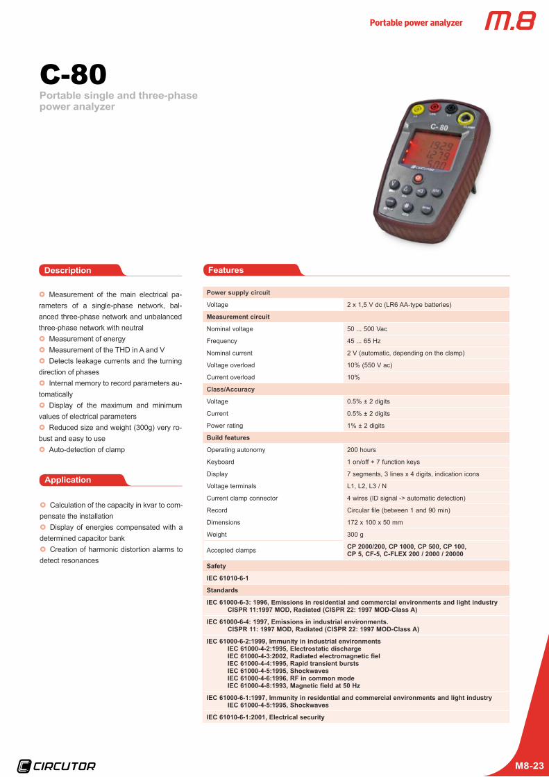
C-80
Power supply circuit
Voltage 2 x 1,5 V dc (LR6 AA-type batteries)
Measurement circuit
Nominal voltage 50 ... 500 Vac
Frequency 45 ... 65 Hz
Nominal current 2 V (automatic, depending on the clamp)
Voltage overload 10% (550 V ac)
Current overload 10%
Class/Accuracy
Voltage 0.5% ± 2 digits
Current 0.5% ± 2 digits
Power rating 1% ± 2 digits
Build features
Operating autonomy 200 hours
Keyboard 1 on/off + 7 function keys
Display 7 segments, 3 lines x 4 digits, indication icons
Voltage terminals L1, L2, L3 / N
Current clamp connector 4 wires (ID signal -> automatic detection)
Record Circular file (between 1 and 90 min)
Dimensions 172 x 100 x 50 mm
Weight 300 g
Accepted clamps CP 2000/200, CP 1000, CP 500, CP 100, CP 5, CF-5, C-FLEX 200 / 2000 / 20000
Safety
IEC 61010-6-1
Standards
IEC 61000-6-3: 1996, Emissions in residential and commercial environments and light industryCISPR 11:1997 MOD, Radiated (CISPR 22: 1997 MOD-Class A)
IEC 61000-6-4: 1997, Emissions in industrial environments.CISPR 11: 1997 MOD, Radiated (CISPR 22: 1997 MOD-Class A)
IEC 61000-6-2:1999, Immunity in industrial environmentsIEC 61000-4-2:1995, Electrostatic dischargeIEC 61000-4-3:2002, Radiated electromagnetic fielIEC 61000-4-4:1995, Rapid transient burstsIEC 61000-4-5:1995, ShockwavesIEC 61000-4-6:1996, RF in common modeIEC 61000-4-8:1993, Magnetic field at 50 Hz
IEC 61000-6-1:1997, Immunity in residential and commercial environments and light industryIEC 61000-4-5:1995, Shockwaves
IEC 61010-6-1:2001, Electrical security
x} Measurement of the main electrical pa-rameters of a single-phase network, bal-anced three-phase network and unbalanced three-phase network with neutral x} Measurement of energyx} Measurement of the THD in A and Vx} Detects leakage currents and the turning
direction of phasesx} Internal memory to record parameters au-
tomaticallyx} Display of the maximum and minimum
values of electrical parametersx} Reduced size and weight (300g) very ro-
bust and easy to usex} Auto-detection of clamp
FeaturesDescription
Application
x} Calculation of the capacity in kvar to com-pensate the installationx} Display of energies compensated with a
determined capacitor bankx} Creation of harmonic distortion alarms to
detect resonances
Portable power analyzer
M8-24
Analyzer Clamps Type Code
C-80 - C-80, Power analyzer M80120
Kits
C-80 CPR-1000 C-80 / 1000 M80121
C-80 CP-2000/200 C-80 / 2000 M80122
C-80 C-FLEX 20k / 2k / 200 A, 45 cm C-80 / C-FLEX 45 M80123
C-80 C-FLEX 20k / 2k / 200 A, 80 cm C-80 / C-FLEX 80 M80124
C-80 C-FLEX 20k / 2k / 200 A, 45 cm + CF-5A C-80 / C-FLEX 45 M80125
References
All kits include 3 voltage cables + case
ParameterSymbol (unit)
Balanced Three-phase / Single-phase system
Instantaneous Maximum Minimum
Voltage V
Current A -
Frequency Hz
Active power W -
Reactive power (L and C) var -
Apparent power V · A -
Power factor PF -
Cos cos -
Active energy W · h - -
Power factor (L) var · h L - -
Power factor (C) var · h C - -
THD (%) U, I % THD -
MD (Max demand) PD -
Parameters measured
Portable single and three-phase power analyzer
C-80
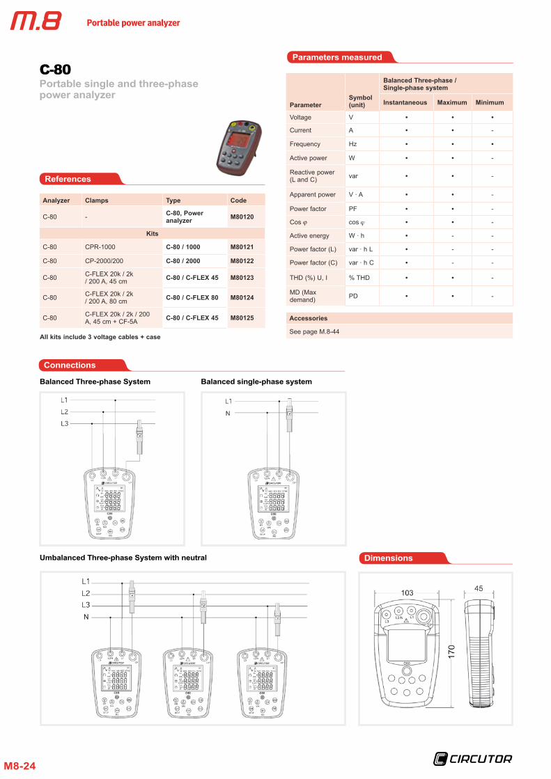
Connections
Dimensions
Balanced Three-phase System
Umbalanced Three-phase System with neutral
Balanced single-phase system
Accessories
See page M.8-44
Portable power analyzer
M8-25
Clamps
Portable single and three-phase power analyzer
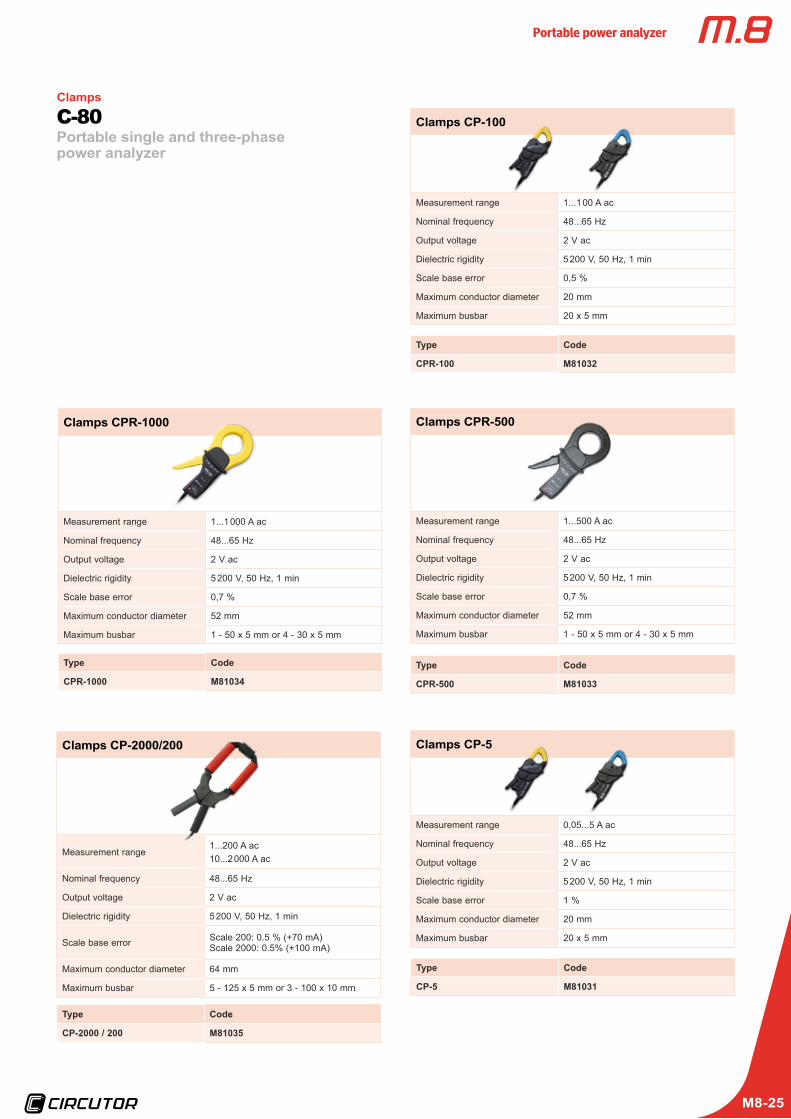
C-80 Clamps CP-100
Measurement range 1...1 00 A ac
Nominal frequency 48...65 Hz
Output voltage 2 V ac
Dielectric rigidity 5 200 V, 50 Hz, 1 min
Scale base error 0,5 %
Maximum conductor diameter 20 mm
Maximum busbar 20 x 5 mm
Type Code
CPR-100 M81032
Clamps CPR-1000
Measurement range 1...1 000 A ac
Nominal frequency 48...65 Hz
Output voltage 2 V ac
Dielectric rigidity 5 200 V, 50 Hz, 1 min
Scale base error 0,7 %
Maximum conductor diameter 52 mm
Maximum busbar 1 - 50 x 5 mm or 4 - 30 x 5 mm
Type Code
CPR-1000 M81034
Clamps CP-2000/200
Measurement range1...200 A ac10...2 000 A ac
Nominal frequency 48...65 Hz
Output voltage 2 V ac
Dielectric rigidity 5 200 V, 50 Hz, 1 min
Scale base error Scale 200: 0.5 % (+70 mA)Scale 2000: 0.5% (+100 mA)
Maximum conductor diameter 64 mm
Maximum busbar 5 - 125 x 5 mm or 3 - 100 x 10 mm
Type Code
CP-2000 / 200 M81035
Clamps CPR-500
Measurement range 1...500 A ac
Nominal frequency 48...65 Hz
Output voltage 2 V ac
Dielectric rigidity 5 200 V, 50 Hz, 1 min
Scale base error 0,7 %
Maximum conductor diameter 52 mm
Maximum busbar 1 - 50 x 5 mm or 4 - 30 x 5 mm
Type Code
CPR-500 M81033
Clamps CP-5
Measurement range 0,05...5 A ac
Nominal frequency 48...65 Hz
Output voltage 2 V ac
Dielectric rigidity 5 200 V, 50 Hz, 1 min
Scale base error 1 %
Maximum conductor diameter 20 mm
Maximum busbar 20 x 5 mm
Type Code
CP-5 M81031
Portable power analyzer
M8-26
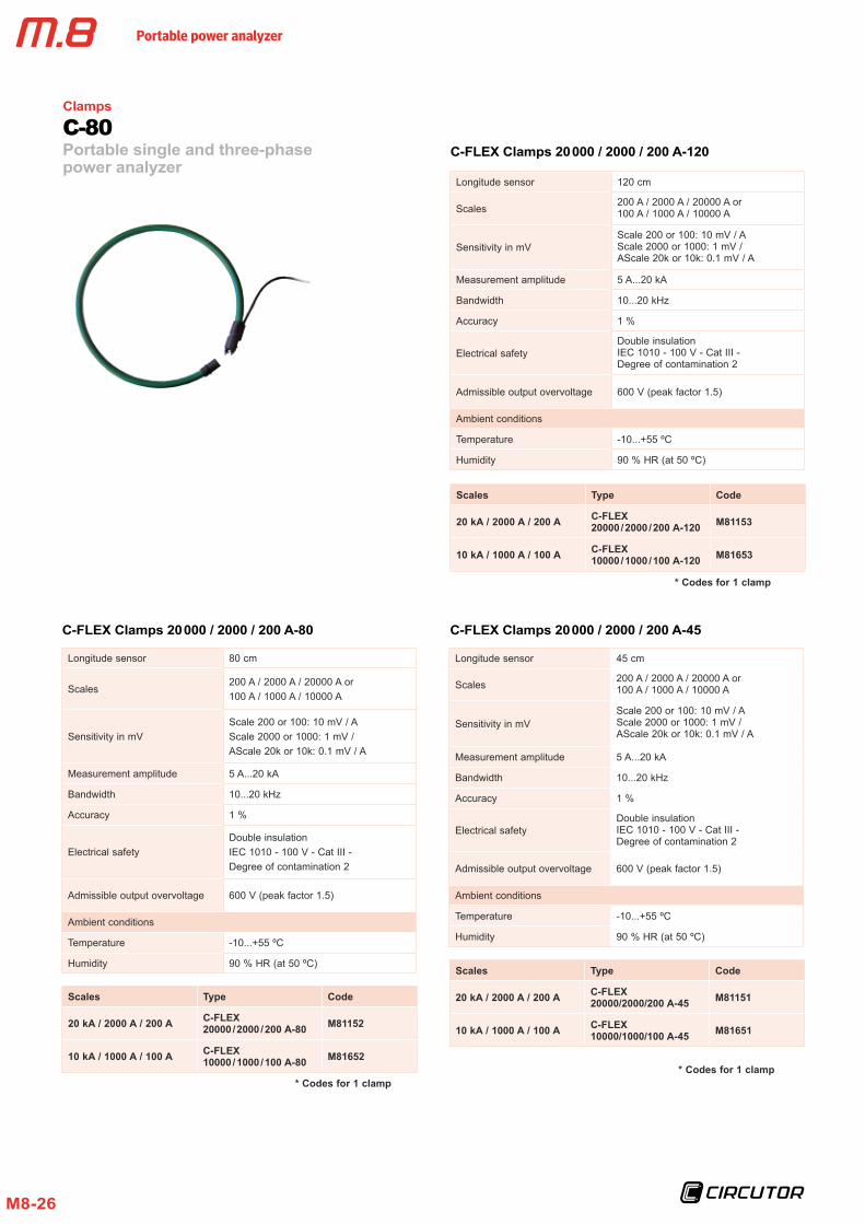
C-FLEX Clamps 20 000 / 2000 / 200 A-80
Longitude sensor 80 cm
Scales200 A / 2000 A / 20000 A or100 A / 1000 A / 10000 A
Sensitivity in mVScale 200 or 100: 10 mV / AScale 2000 or 1000: 1 mV / AScale 20k or 10k: 0.1 mV / A
Measurement amplitude 5 A...20 kA
Bandwidth 10...20 kHz
Accuracy 1 %
Electrical safetyDouble insulationIEC 1010 - 100 V - Cat III - Degree of contamination 2
Admissible output overvoltage 600 V (peak factor 1.5)
Ambient conditions
Temperature -10...+55 ºC
Humidity 90 % HR (at 50 ºC)
Scales Type Code
20 kA / 2000 A / 200 A C-FLEX 20000 / 2000 / 200 A-80 M81152
10 kA / 1000 A / 100 A C-FLEX 10000 / 1000 / 100 A-80 M81652
* Codes for 1 clamp
C-FLEX Clamps 20 000 / 2000 / 200 A-120
Longitude sensor 120 cm
Scales200 A / 2000 A / 20000 A or100 A / 1000 A / 10000 A
Sensitivity in mVScale 200 or 100: 10 mV / AScale 2000 or 1000: 1 mV / AScale 20k or 10k: 0.1 mV / A
Measurement amplitude 5 A...20 kA
Bandwidth 10...20 kHz
Accuracy 1 %
Electrical safetyDouble insulationIEC 1010 - 100 V - Cat III - Degree of contamination 2
Admissible output overvoltage 600 V (peak factor 1.5)
Ambient conditions
Temperature -10...+55 ºC
Humidity 90 % HR (at 50 ºC)
Scales Type Code
20 kA / 2000 A / 200 A C-FLEX 20000 / 2000 / 200 A-120 M81153
10 kA / 1000 A / 100 A C-FLEX 10000 / 1000 / 100 A-120 M81653
* Codes for 1 clamp
C-FLEX Clamps 20 000 / 2000 / 200 A-45
Longitude sensor 45 cm
Scales 200 A / 2000 A / 20000 A or100 A / 1000 A / 10000 A
Sensitivity in mVScale 200 or 100: 10 mV / AScale 2000 or 1000: 1 mV / AScale 20k or 10k: 0.1 mV / A
Measurement amplitude 5 A...20 kA
Bandwidth 10...20 kHz
Accuracy 1 %
Electrical safetyDouble insulationIEC 1010 - 100 V - Cat III - Degree of contamination 2
Admissible output overvoltage 600 V (peak factor 1.5)
Ambient conditions
Temperature -10...+55 ºC
Humidity 90 % HR (at 50 ºC)
Scales Type Code
20 kA / 2000 A / 200 A C-FLEX 20000/2000/200 A-45 M81151
10 kA / 1000 A / 100 A C-FLEX 10000/1000/100 A-45 M81651
Clamps
Portable single and three-phase power analyzer
C-80
* Codes for 1 clamp
Portable power analyzer
M8-27
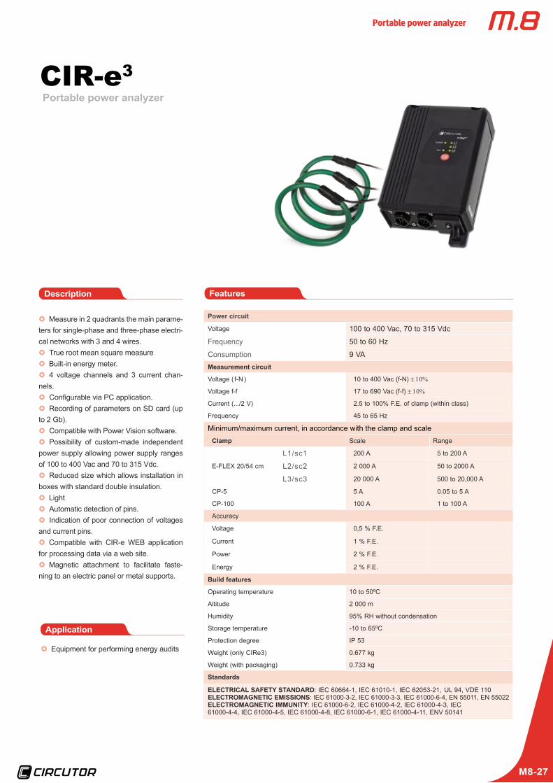
Portable power analyzerCIR-e3
Power circuit
Voltage 100 to 400 Vac, 70 to 315 Vdc
Frequency 50 to 60 Hz
Consumption 9 VAMeasurement circuit
Voltage ( f-N ) 10 to 400 Vac (f-N) ± 10%
Voltage f-f 17 to 690 Vac (f-f) ± 10%
Current (.../2 V) 2.5 to 100% F.E. of clamp (within class)
Frequency 45 to 65 Hz
Minimum/maximum current, in accordance with the clamp and scaleClamp Scale Range
E-FLEX 20/54 cm
L1/sc1 200 A 5 to 200 A
L2/sc2 2 000 A 50 to 2000 A
L3/sc3 20 000 A 500 to 20,000 A
CP-5 5 A 0.05 to 5 A
CP-100 100 A 1 to 100 A
Accuracy
Voltage 0,5 % F.E.
Current 1 % F.E.
Power 2 % F.E.
Energy 2 % F.E.
Build features
Operating temperature 10 to 50ºC
Altitude 2 000 m
Humidity 95% RH without condensation
Storage temperature -10 to 65ºC
Protection degree IP 53
Weight (only CIRe3) 0.677 kg
Weight (with packaging) 0.733 kg
Standards
ELECTRICAL SAFETY STANDARD: IEC 60664-1, IEC 61010-1, IEC 62053-21, UL 94, VDE 110ELECTROMAGNETIC EMISSIONS: IEC 61000-3-2, IEC 61000-3-3, IEC 61000-6-4, EN 55011, EN 55022ELECTROMAGNETIC IMMUNITY: IEC 61000-6-2, IEC 61000-4-2, IEC 61000-4-3, IEC 61000-4-4, IEC 61000-4-5, IEC 61000-4-8, IEC 61000-6-1, IEC 61000-4-11, ENV 50141
x} Measure in 2 quadrants the main parame-ters for single-phase and three-phase electri-cal networks with 3 and 4 wires.x} True root mean square measurex} Built-in energy meter.x} 4 voltage channels and 3 current chan-
nels.x} Configurable via PC application.x} Recording of parameters on SD card (up
to 2 Gb).x} Compatible with Power Vision software.x} Possibility of custom-made independent
power supply allowing power supply ranges of 100 to 400 Vac and 70 to 315 Vdc.x} Reduced size which allows installation in
boxes with standard double insulation.x} Lightx} Automatic detection of pins.x} Indication of poor connection of voltages
and current pins.x} Compatible with CIR-e WEB application
for processing data via a web site.x} Magnetic attachment to facilitate faste-
ning to an electric panel or metal supports.
FeaturesDescription
x} Equipment for performing energy audits
Application
Portable power analyzer
M8-28
Portable power analyzerCIR-e3
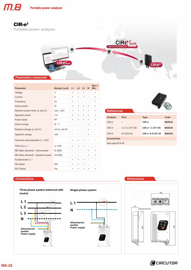
References
Parameters measured
L 1
N
Alimentación auxiliarPower supply
N
Alimentación auxiliarPower supply
L 1L 2L 3
Parameter Symbol (unit) L1 L2 L3 IIIMax./Min.
Voltage V -
Current A -
Frequency Hz - - -
Active power W
Reactive power factor (L and C) varL, varC
Apparent power V ·A
Power factor PF
Active energy W · h - - - -
Reactive energy (L and C) var ·hL,var ·hC - - - -
Apparent energy VAh - - - -
Harmonic decomposition U, I (50) - -
THD (%) U, I % THD - -
MD (Max demand) - Active power W (MD) - - -
MD (Max demand) - Apparent power VA (MD) - - -
Fundamental U, I - -
WA flicker WA - -
PST flicker Pst
Analyzer Pins Type Code
CIR-e3 - CIR-e3 M85020
CIR-e3 3 x 3 x CP-100 CIR-e3 / 3 CP-100 M85030
CIR-e3 E-FLEX 54 CIR-e3 E-FLEX 54 M85000
Accessories
See page M.8-45
Three-phase system balanced with neutral
Single-phase system
Connections Dimensions
Portable power analyzer
M8-29
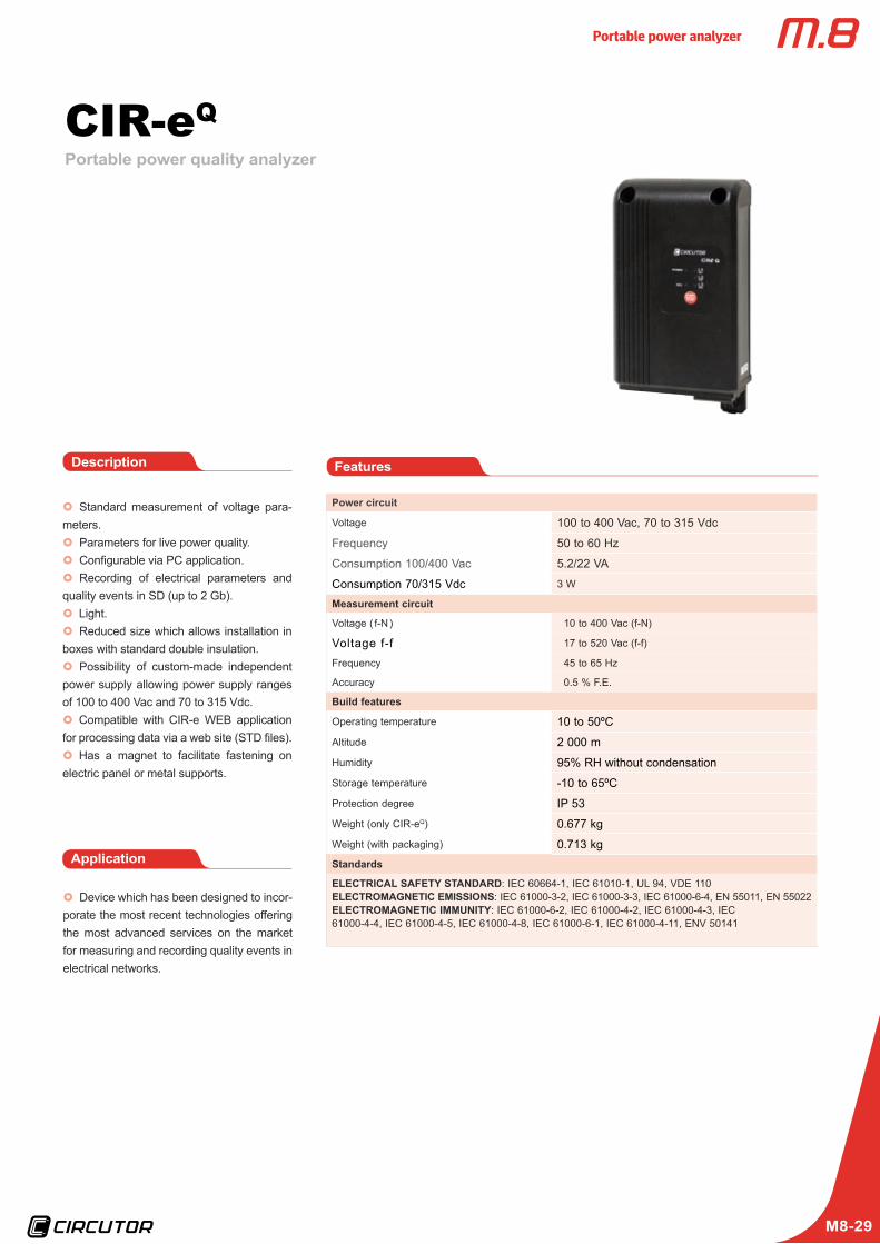
CIR-eQPortable power quality analyzer
x} Standard measurement of voltage para-meters.x} Parameters for live power quality.x} Configurable via PC application.x} Recording of electrical parameters and
quality events in SD (up to 2 Gb).x} Light.x} Reduced size which allows installation in
boxes with standard double insulation.x} Possibility of custom-made independent
power supply allowing power supply ranges of 100 to 400 Vac and 70 to 315 Vdc.x} Compatible with CIR-e WEB application
for processing data via a web site (STD files).x} Has a magnet to facilitate fastening on
electric panel or metal supports.
Description
Power circuit
Voltage 100 to 400 Vac, 70 to 315 Vdc
Frequency 50 to 60 Hz
Consumption 100/400 Vac 5.2/22 VA
Consumption 70/315 Vdc 3 W
Measurement circuit
Voltage ( f-N ) 10 to 400 Vac (f-N)
Voltage f-f 17 to 520 Vac (f-f)
Frequency 45 to 65 Hz
Accuracy 0.5 % F.E.
Build features
Operating temperature 10 to 50ºC
Altitude 2 000 m
Humidity 95% RH without condensation
Storage temperature -10 to 65ºC
Protection degree IP 53
Weight (only CIR-eQ) 0.677 kg
Weight (with packaging) 0.713 kgStandards
ELECTRICAL SAFETY STANDARD: IEC 60664-1, IEC 61010-1, UL 94, VDE 110ELECTROMAGNETIC EMISSIONS: IEC 61000-3-2, IEC 61000-3-3, IEC 61000-6-4, EN 55011, EN 55022ELECTROMAGNETIC IMMUNITY: IEC 61000-6-2, IEC 61000-4-2, IEC 61000-4-3, IEC 61000-4-4, IEC 61000-4-5, IEC 61000-4-8, IEC 61000-6-1, IEC 61000-4-11, ENV 50141
Features
Application
x} Device which has been designed to incor-porate the most recent technologies offering the most advanced services on the market for measuring and recording quality events in electrical networks.
Portable power analyzer
M8-30
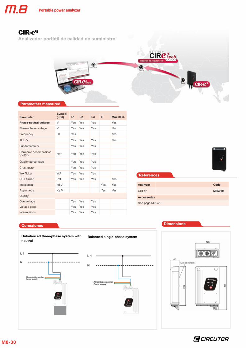
Analizador portátil de calidad de suministro CIR-eQ
Conexiones
ParameterSymbol (unit) L1 L2 L3 III Max./Min.
Phase-neutral voltage V Yes Yes Yes Yes
Phase-phase voltage V Yes Yes Yes Yes
Frequency Hz Yes Yes
THD V Yes Yes Yes Yes
Fundamental V Yes Yes Yes
Harmonic decomposition V (50º) Har Yes Yes Yes
Quality percentage Yes Yes Yes
Crest factor Yes Yes Yes
WA flicker WA Yes Yes Yes
PST flicker Pst Yes Yes Yes Yes
Imbalance kd V Yes Yes
Asymmetry Ka V Yes Yes
Quality
Overvoltage Yes Yes Yes
Voltage gaps Yes Yes Yes
Interruptions Yes Yes Yes
Parameters measured
Analyzer Code
CIR-eQ M85010
Accessories
See page M.8-45
References
Unbalanced three-phase system with neutral
Balanced single-phase system
Dimensions
Portable power analyzer
M8-31
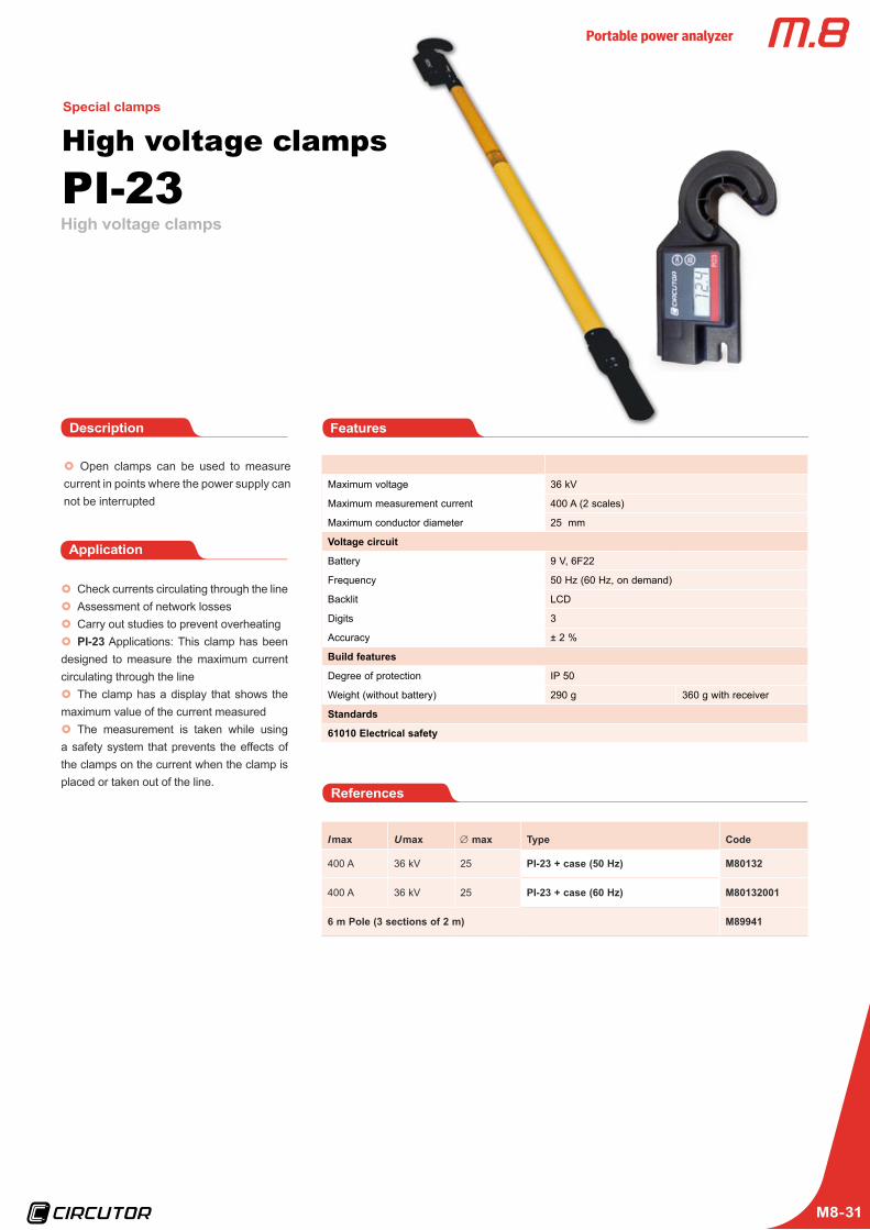
x} Open clamps can be used to measure current in points where the power supply can not be interrupted
FeaturesDescription
Application
x} Check currents circulating through the linex} Assessment of network lossesx} Carry out studies to prevent overheatingx} PI-23 Applications: This clamp has been
designed to measure the maximum current circulating through the linex} The clamp has a display that shows the
maximum value of the current measuredx} The measurement is taken while using
a safety system that prevents the effects of the clamps on the current when the clamp is placed or taken out of the line.
I max U max ∅ max Type Code
400 A 36 kV 25 PI-23 + case (50 Hz) M80132
400 A 36 kV 25 PI-23 + case (60 Hz) M80132001
6 m Pole (3 sections of 2 m) M89941
References
Maximum voltage 36 kV
Maximum measurement current 400 A (2 scales)
Maximum conductor diameter 25 mm
Voltage circuit
Battery 9 V, 6F22
Frequency 50 Hz (60 Hz, on demand)
Backlit LCD
Digits 3
Accuracy ± 2 %
Build features
Degree of protection IP 50
Weight (without battery) 290 g 360 g with receiver
Standards
61010 Electrical safety
High voltage clamps
High voltage clamps PI-23
Special clamps
Portable power analyzer
M8-32
Clamps with memory
Clamps with logger CPL
Special clamps
Voltage circuit
Through an external power supply unit 230 Vac (± 15 %)
Self-power supply I >15 % In
Frequency 50 ... 60 Hz
Measurement range 1 at 100% In
Accuracy with external power supply 1 % of the reading (± 2 digits)
Memory 128 KB ( > 8000 records)
Type of memory Linear
Safety Category III 640 V (self-power supply), EN 61010
Standards
EN 60664, VDE 0110, UL 94, EN 60801, EN 6100, EN 61010-1
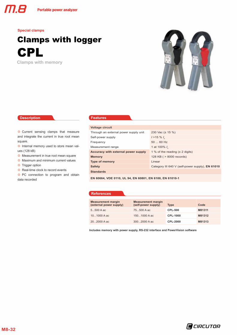
x} Current sensing clamps that measure and integrate the current in true root mean square. x} Internal memory used to store mean val-
ues (128 kB)x} Measurement in true root mean squarex} Maximum and minimum current valuesx} Trigger optionx} Real-time clock to record eventsx} PC connection to program and obtain
data recorded
FeaturesDescription
Measurement margin (external power supply)
Measurement margin (self-power supply) Type Code
5...500 A ac 75...500 A ac CPL-500 M81311
10...1000 A ac 150...1000 A ac CPL-1000 M81312
20...2000 A ac 300...2000 A ac CPL-2000 M81313
References
Includes memory with power supply, RS-232 interface and PowerVision software
Portable power analyzer
M8-33
Earth resistance meterT-3V
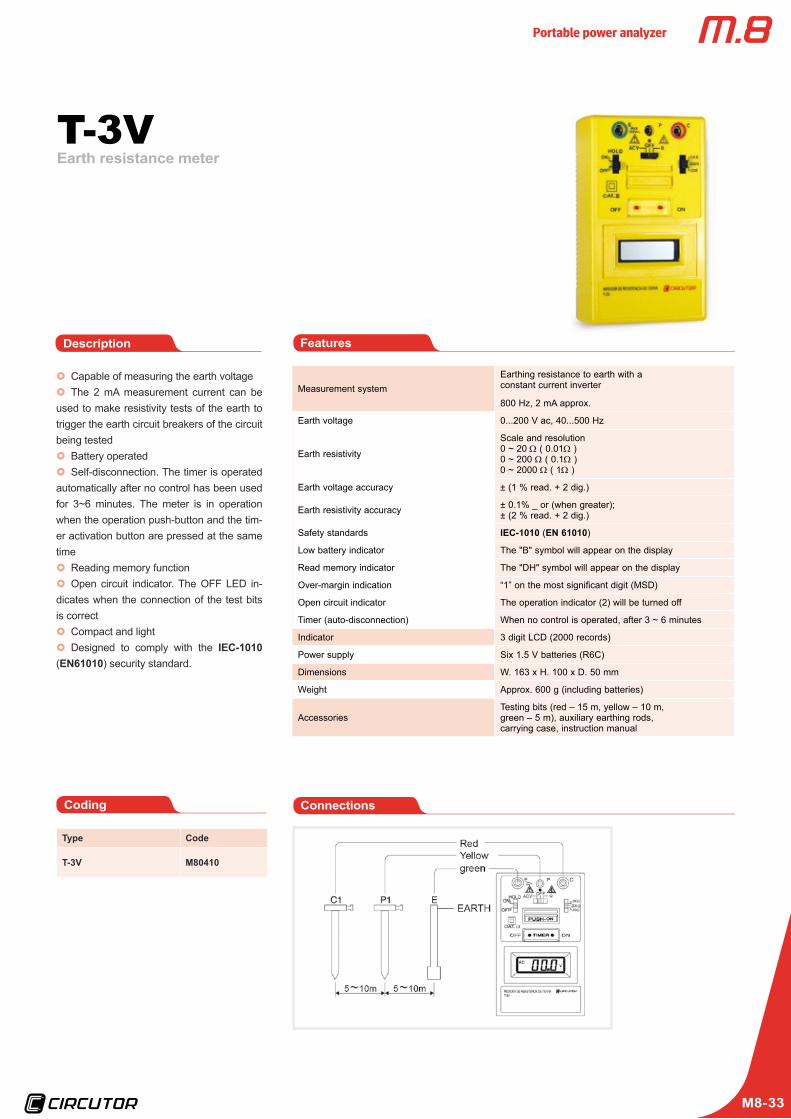
x} Capable of measuring the earth voltagex} The 2 mA measurement current can be
used to make resistivity tests of the earth to trigger the earth circuit breakers of the circuit being testedx} Battery operatedx} Self-disconnection. The timer is operated
automatically after no control has been used for 3~6 minutes. The meter is in operation when the operation push-button and the tim-er activation button are pressed at the same timex} Reading memory functionx} Open circuit indicator. The OFF LED in-
dicates when the connection of the test bits is correctx} Compact and lightx} Designed to comply with the IEC-1010
(EN61010) security standard.
FeaturesDescription
Coding
Measurement systemEarthing resistance to earth with a constant current inverter
800 Hz, 2 mA approx.
Earth voltage 0...200 V ac, 40...500 Hz
Earth resistivity
Scale and resolution0 ~ 20 Ω ( 0.01Ω )0 ~ 200 Ω ( 0.1Ω )0 ~ 2000 Ω ( 1Ω )
Earth voltage accuracy ± (1 % read. + 2 dig.)
Earth resistivity accuracy ± 0.1% _ or (when greater);± (2 % read. + 2 dig.)
Safety standards IEC-1010 (EN 61010)
Low battery indicator The "B" symbol will appear on the display
Read memory indicator The "DH" symbol will appear on the display
Over-margin indication “1” on the most significant digit (MSD)
Open circuit indicator The operation indicator (2) will be turned off
Timer (auto-disconnection) When no control is operated, after 3 ~ 6 minutes
Indicator 3 digit LCD (2000 records)
Power supply Six 1.5 V batteries (R6C)
Dimensions W. 163 x H. 100 x D. 50 mm
Weight Approx. 600 g (including batteries)
AccessoriesTesting bits (red – 15 m, yellow – 10 m, green – 5 m), auxiliary earthing rods, carrying case, instruction manual
Type Code
T-3V M80410
Connections
Portable power analyzer
M8-34
Insulation meterMEG-S
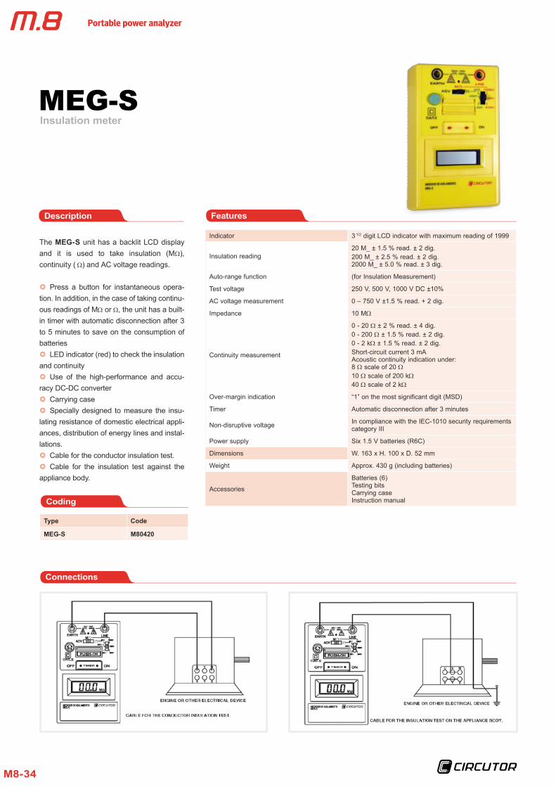
The MEG-S unit has a backlit LCD display and it is used to take insulation (MΩ), continuity ( Ω) and AC voltage readings.
x} Press a button for instantaneous opera-tion. In addition, in the case of taking continu-ous readings of MΩ or Ω, the unit has a built-in timer with automatic disconnection after 3 to 5 minutes to save on the consumption of batteriesx} LED indicator (red) to check the insulation
and continuityx} Use of the high-performance and accu-
racy DC-DC converterx} Carrying casex} Specially designed to measure the insu-
lating resistance of domestic electrical appli-ances, distribution of energy lines and instal-lations.x} Cable for the conductor insulation test.x} Cable for the insulation test against the
appliance body.
FeaturesDescription
Coding
Indicator 3 1/2 digit LCD indicator with maximum reading of 1999
Insulation reading20 M_ ± 1.5 % read. ± 2 dig.200 M_ ± 2.5 % read. ± 2 dig. 2000 M_ ± 5.0 % read. ± 3 dig.
Auto-range function (for Insulation Measurement)
Test voltage 250 V, 500 V, 1000 V DC ±10%
AC voltage measurement 0 – 750 V ±1.5 % read. + 2 dig.
Impedance 10 MΩ
Continuity measurement
0 - 20 Ω ± 2 % read. ± 4 dig.0 - 200 Ω ± 1.5 % read. ± 2 dig.0 - 2 kΩ ± 1.5 % read. ± 2 dig.Short-circuit current 3 mA Acoustic continuity indication under: 8 Ω scale of 20 Ω10 Ω scale of 200 kΩ40 Ω scale of 2 kΩ
Over-margin indication “1” on the most significant digit (MSD)
Timer Automatic disconnection after 3 minutes
Non-disruptive voltage In compliance with the IEC-1010 security requirementscategory III
Power supply Six 1.5 V batteries (R6C)
Dimensions W. 163 x H. 100 x D. 52 mm
Weight Approx. 430 g (including batteries)
Accessories
Batteries (6)Testing bits Carrying case Instruction manual
Type Code
MEG-S M80420
Connections
Portable power analyzer
M8-35
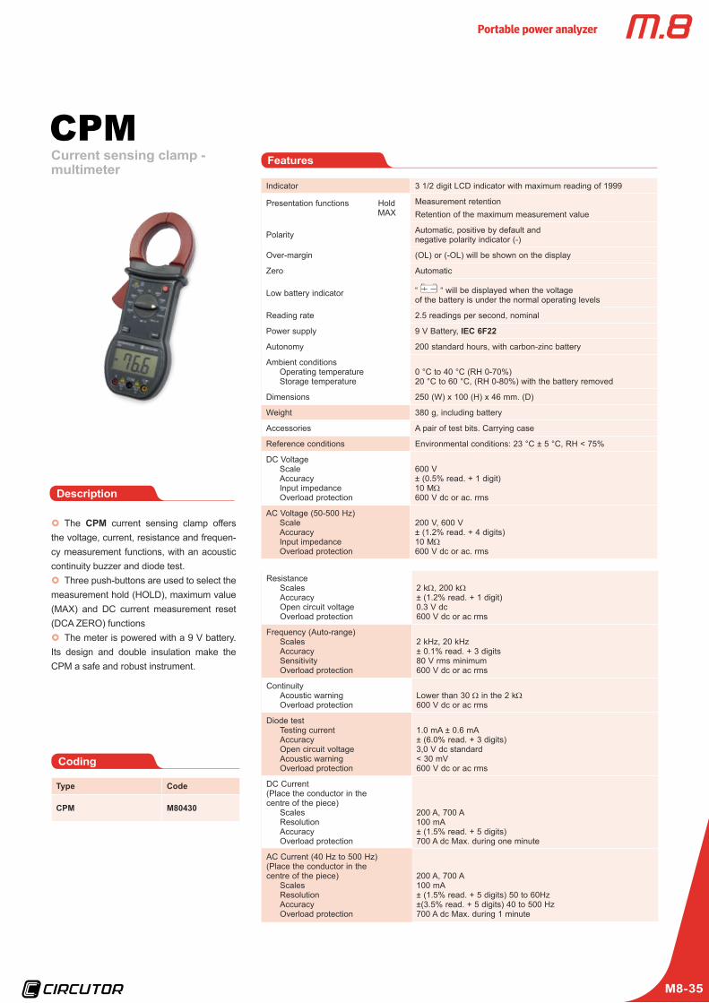
Current sensing clamp - multimeter
CPM
x} The CPM current sensing clamp offers the voltage, current, resistance and frequen-cy measurement functions, with an acoustic continuity buzzer and diode test.x} Three push-buttons are used to select the
measurement hold (HOLD), maximum value (MAX) and DC current measurement reset (DCA ZERO) functionsx} The meter is powered with a 9 V battery.
Its design and double insulation make the CPM a safe and robust instrument.
Features
Description
Coding
Indicator 3 1/2 digit LCD indicator with maximum reading of 1999
Presentation functions Hold MAX
Measurement retentionRetention of the maximum measurement value
Polarity Automatic, positive by default andnegative polarity indicator (-)
Over-margin (OL) or (-OL) will be shown on the display
Zero Automatic
Low battery indicator “ “ will be displayed when the voltageof the battery is under the normal operating levels
Reading rate 2.5 readings per second, nominal
Power supply 9 V Battery, IEC 6F22
Autonomy 200 standard hours, with carbon-zinc battery
Ambient conditionsOperating temperature Storage temperature
0 °C to 40 °C (RH 0-70%)20 °C to 60 °C, (RH 0-80%) with the battery removed
Dimensions 250 (W) x 100 (H) x 46 mm. (D)
Weight 380 g, including battery
Accessories A pair of test bits. Carrying case
Reference conditions Environmental conditions: 23 °C ± 5 °C, RH < 75%
DC VoltageScale Accuracy Input impedance Overload protection
600 V± (0.5% read. + 1 digit) 10 MΩ600 V dc or ac. rms
AC Voltage (50-500 Hz)Scale Accuracy Input impedance Overload protection
200 V, 600 V± (1.2% read. + 4 digits) 10 MΩ600 V dc or ac. rms
Type Code
CPM M80430
ResistanceScales Accuracy Open circuit voltage Overload protection
2 kΩ, 200 kΩ± (1.2% read. + 1 digit)0.3 V dc600 V dc or ac rms
Frequency (Auto-range)ScalesAccuracySensitivity Overload protection
2 kHz, 20 kHz± 0.1% read. + 3 digits80 V rms minimum600 V dc or ac rms
ContinuityAcoustic warning Overload protection
Lower than 30 Ω in the 2 kΩ600 V dc or ac rms
Diode testTesting current Accuracy Open circuit voltage Acoustic warning Overload protection
1.0 mA ± 0.6 mA± (6.0% read. + 3 digits)3,0 V dc standard< 30 mV600 V dc or ac rms
DC Current (Place the conductor in the centre of the piece)
Scales Resolution Accuracy Overload protection
200 A, 700 A100 mA± (1.5% read. + 5 digits)700 A dc Max. during one minute
AC Current (40 Hz to 500 Hz)(Place the conductor in the centre of the piece)
Scales Resolution Accuracy Overload protection
200 A, 700 A100 mA± (1.5% read. + 5 digits) 50 to 60Hz±(3.5% read. + 5 digits) 40 to 500 Hz700 A dc Max. during 1 minute
Portable power analyzer
M8-36
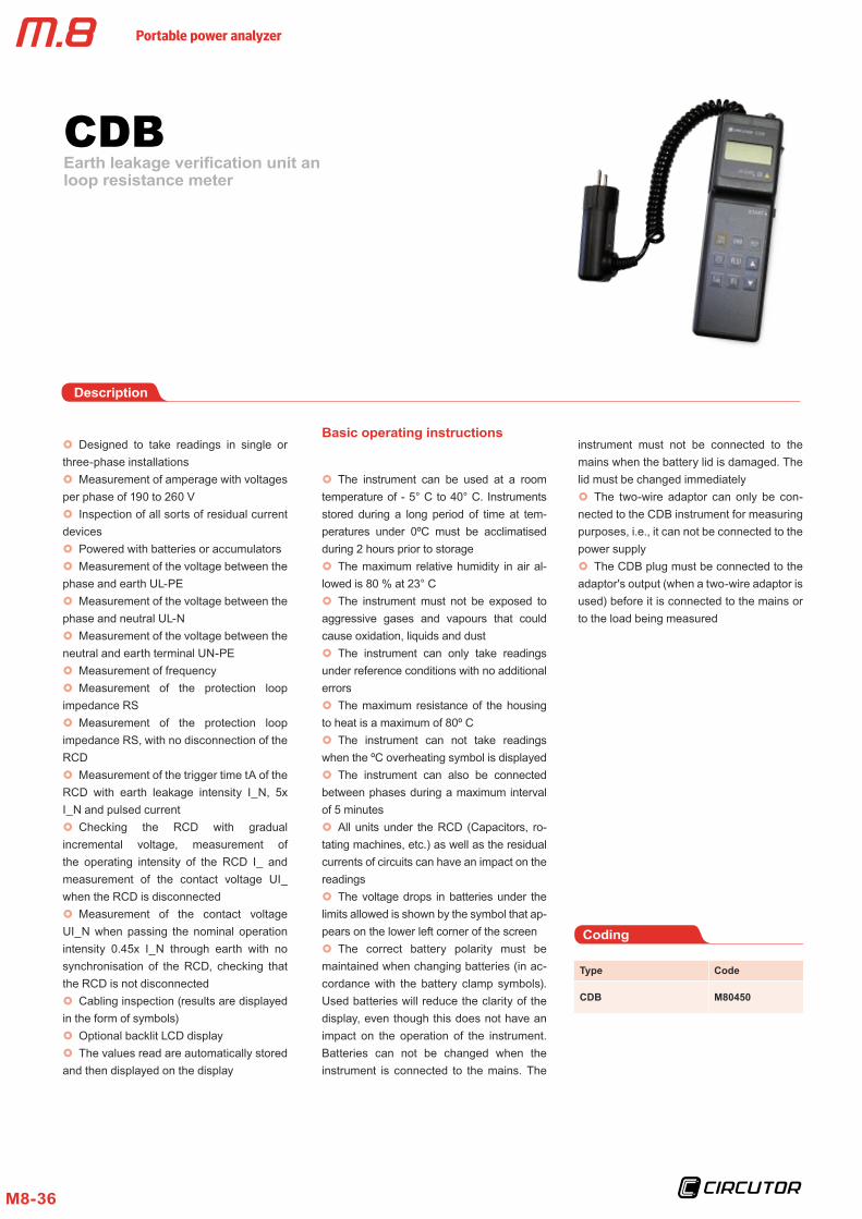
Earth leakage verification unit an loop resistance meter
CDB
Coding
Type Code
CDB M80450
Description
x} Designed to take readings in single or three-phase installationsx} Measurement of amperage with voltages
per phase of 190 to 260 Vx} Inspection of all sorts of residual current
devicesx} Powered with batteries or accumulatorsx} Measurement of the voltage between the
phase and earth UL-PEx} Measurement of the voltage between the
phase and neutral UL-Nx} Measurement of the voltage between the
neutral and earth terminal UN-PEx} Measurement of frequencyx} Measurement of the protection loop
impedance RSx} Measurement of the protection loop
impedance RS, with no disconnection of the RCDx} Measurement of the trigger time tA of the
RCD with earth leakage intensity I_N, 5x I_N and pulsed currentx} Checking the RCD with gradual
incremental voltage, measurement of the operating intensity of the RCD I_ and measurement of the contact voltage UI_ when the RCD is disconnected x} Measurement of the contact voltage
UI_N when passing the nominal operation intensity 0.45x I_N through earth with no synchronisation of the RCD, checking that the RCD is not disconnectedx} Cabling inspection (results are displayed
in the form of symbols)x} Optional backlit LCD displayx} The values read are automatically stored
and then displayed on the display
Basic operating instructions
x} The instrument can be used at a room temperature of - 5° C to 40° C. Instruments stored during a long period of time at tem-peratures under 0ºC must be acclimatised during 2 hours prior to storagex} The maximum relative humidity in air al-
lowed is 80 % at 23° Cx} The instrument must not be exposed to
aggressive gases and vapours that could cause oxidation, liquids and dustx} The instrument can only take readings
under reference conditions with no additional errorsx} The maximum resistance of the housing
to heat is a maximum of 80º Cx} The instrument can not take readings
when the ºC overheating symbol is displayedx} The instrument can also be connected
between phases during a maximum interval of 5 minutes x} All units under the RCD (Capacitors, ro-
tating machines, etc.) as well as the residual currents of circuits can have an impact on the readingsx} The voltage drops in batteries under the
limits allowed is shown by the symbol that ap-pears on the lower left corner of the screenx} The correct battery polarity must be
maintained when changing batteries (in ac-cordance with the battery clamp symbols). Used batteries will reduce the clarity of the display, even though this does not have an impact on the operation of the instrument. Batteries can not be changed when the instrument is connected to the mains. The
instrument must not be connected to the mains when the battery lid is damaged. The lid must be changed immediatelyx} The two-wire adaptor can only be con-
nected to the CDB instrument for measuring purposes, i.e., it can not be connected to the power supplyx} The CDB plug must be connected to the
adaptor's output (when a two-wire adaptor is used) before it is connected to the mains or to the load being measured
Portable power analyzer
M8-37
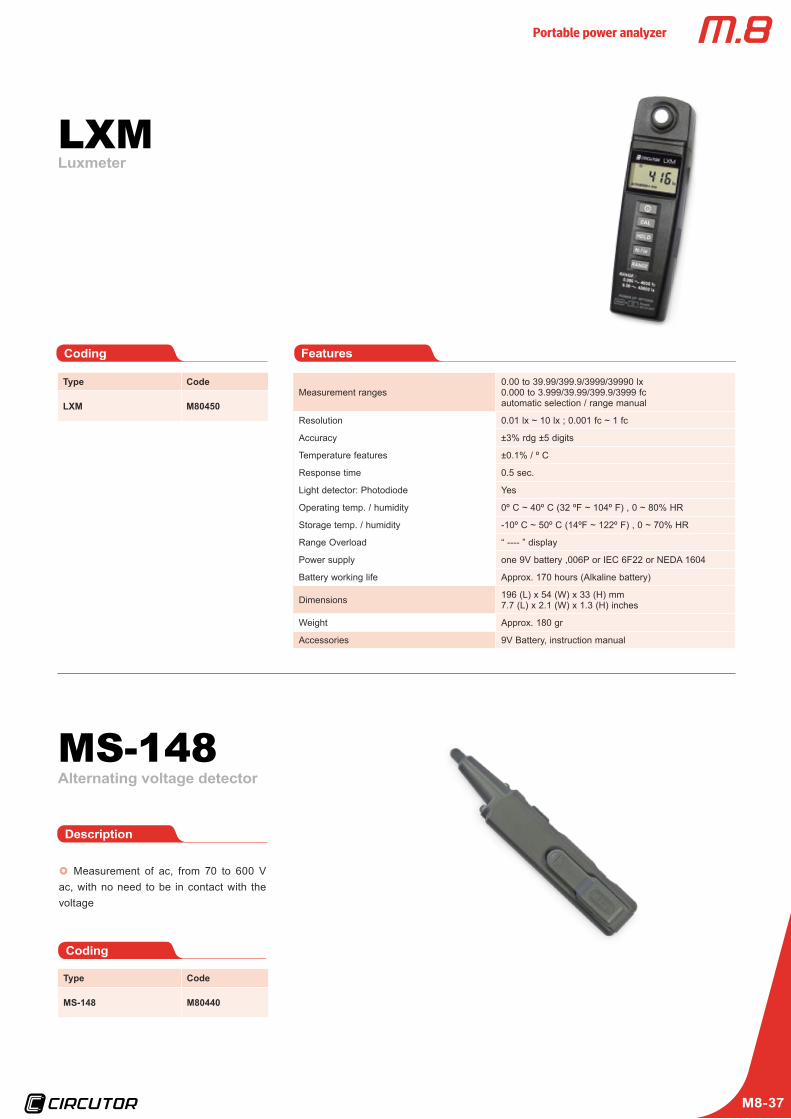
LuxmeterLXM
FeaturesCoding
Measurement ranges0.00 to 39.99/399.9/3999/39990 lx0.000 to 3.999/39.99/399.9/3999 fcautomatic selection / range manual
Resolution 0.01 lx ~ 10 lx ; 0.001 fc ~ 1 fc
Accuracy ±3% rdg ±5 digits
Temperature features ±0.1% / º C
Response time 0.5 sec.
Light detector: Photodiode Yes
Operating temp. / humidity 0º C ~ 40º C (32 ºF ~ 104º F) , 0 ~ 80% HR
Storage temp. / humidity -10º C ~ 50º C (14ºF ~ 122º F) , 0 ~ 70% HR
Range Overload “ ---- ” display
Power supply one 9V battery ,006P or IEC 6F22 or NEDA 1604
Battery working life Approx. 170 hours (Alkaline battery)
Dimensions 196 (L) x 54 (W) x 33 (H) mm7.7 (L) x 2.1 (W) x 1.3 (H) inches
Weight Approx. 180 gr
Accessories 9V Battery, instruction manual
Type Code
LXM M80450
Alternating voltage detectorMS-148
x} Measurement of ac, from 70 to 600 V ac, with no need to be in contact with the voltage
Description
Coding
Type Code
MS-148 M80440

Portable power analyzer
M8-38
accesorios AR6Kit with 4 flexible clamps
Code M82533
x} Kit with 4 AM54-Flex flexible clamps with 5 ties
Description
Kit with 3 flexible clamps
Code M82532
x} Kit with 3 AM54-Flex flexible clamps with 5 ties
Description
Flexible clamp
x} AM54-Flex type flexible clamps with coloured clips
Description
Code M82531
Crocodile clamps
Code M89909
x} Crocodile clamps for AR6
Description
Voltage cables
Code M82501
x} Black (UL) voltage cables with 12 ties in 6 colours
Description
AR6 case
Code M82503
x} Deep red AR6 work cover
Description

Portable power analyzer
M8-39
For more information, see M.9 Catalogue
Power Vision Plus
Code M90411
x} Software for the remote management and measurement of the information recorded by the AR5-L portable analyzers and other units manufactured by CIRCUTOR.
x} It is a high-performance tool that increas-es the power of the information recorded by the units.
Description
AR6 case
Code M82504
x} Transport case (trolley type) for AR6
Description
Lexan front panel
Code M82506
x} Lexan front panel with phase colours
Description
Power supply
Code M82507
x} Power supply for AR6
Description
AR6 battery
Code M82508
x} Replacement for the internal battery of the AR6 analyzer
Description

Portable power analyzer
M8-40
Includes:x} 80 - 250 V ac Power supplyx} Power supply cablex} Cable to connect the power supply
and the AR5-Lx} Series cable (RS-232) to connect the
power supply and PC
Code M89926
Charging power supply and interface ( RS-232)
Code M89901
Case for AR5 / AR5-L
Code M89905
Carrying bag for AR5 / AR5-L
Code M89904
AR5-L battery
Description
Description
Cover for the AR5-L analyzer, so that it can be transported easily and comfortably
Description
Includes pockets for the following:x} One AR5-L analyzerx} 4 current sensing clamps (CP5, CP100,
CPR500, CPR1000, CP2000 / 200, CF-5 or any kit with flexible clamps)x} Power supply and power supply / voltage
measurement cablesx} Folder with the manuals of PowerVision
and other programsx} Accessories of the AR5-L
analyzer
Description
Replacement for the internal battery of the AR5-L analyzer
AR5-L accessories

Portable power analyzer
M8-41
Code M89921
Case for AR5-L clamps
Code M89923
1000 L Case (with protective foam, for CPR-1000 clamps of the AR5-L analyzer )
2000 L Case
(with protective foam, for CPR-2000 /200 clamps of the AR5-L analyzer)
Code M89924
C-FLEX Case (with protective foam, for C-FLEX clamps of the AR5-L analyzer )
Code M8992F
Case for AR5-L clamps
Description
Includes pockets for the following:x} One AR5-L analyzerx} 4 CPR100 current sensing clampsPower
supply and power supply / voltage measure-ment cables
Description
Includes pockets for the following:x} One AR5-L analyzerx} 4 CPR2000 / 200 current sensing clampsx} Power supply and power supply / voltage
measurement cables
Description
AR5-L accessories
Portable power analyzer
M8-42
Code M8991E
PC Communications cable
For more information, see M.9 Catalogue
Power Vision Plus
Code M806C3
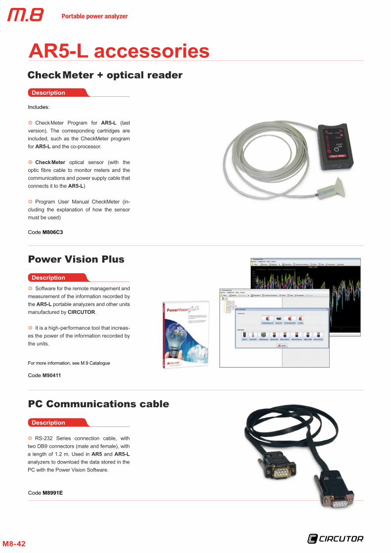
Check Meter + optical readerDescription
Includes:
x} Check Meter Program for AR5-L (last version). The corresponding cartridges are included, such as the CheckMeter program for AR5-L and the co-processor.
x} Check Meter optical sensor (with the optic fibre cable to monitor meters and the communications and power supply cable that connects it to the AR5-L)
x} Program User Manual CheckMeter (in-cluding the explanation of how the sensor must be used)
Code M90411
x} Software for the remote management and measurement of the information recorded by the AR5-L portable analyzers and other units manufactured by CIRCUTOR.
x} It is a high-performance tool that increas-es the power of the information recorded by the units.
Description
Description
x} RS-232 Series connection cable, with two DB9 connectors (male and female), with a length of 1.2 m. Used in AR5 and AR5-L analyzers to download the data stored in the PC with the Power Vision Software.
AR5-L accessories

Portable power analyzer
M8-43
Cable to connect the AR5-L unit to the power supply
Code M8992C
Adaptor cable (3 cables) AR5-L
Code M89917
Adaptor cable (1 cable) AR5-L
Adaptor cable (1 cable) AR5
Code M89922
Code M89932
x} Set of three cables, with a 4-way female connector with colour phase on one end and a 3-pin male connector on the other end.
Description
x} 4-way female connector on one end and 3-pin male connector on the other end.
Description
x} 3-way female connector on one end and 4-pin male connector on the other end, with phase colour.
Description
x} Cable to connect the power supply input and communications between the analyzer and power supply.
Description
AR5-L accessories

Portable power analyzer
M8-44
3 voltage cable replacement kit
Code M89907
C-80 Case
Code M89931
Code M89909
Crocodile clamp (1 unit)
x} Clamp that adapts to the voltage cable and can be connected to an electric panel or sub-panel to measure voltage.
Description
x} Set of 3 cables to connect the voltage in-puts of the C-80 analyzer to an electric panel or sub-panel.
Description
Set of 4 voltage cables
Code M89908
x} Set of 4 cables to connect the voltage inputs of the AR5-L analyzer to an electric panel or sub-panel.
Description
x} Case to carry the C-80 analyzer easily and safely.
Description
AR5-L accessories
C-80 accessories

Portable power analyzer
M8-45
CIR-e3 / CIR-eQ accessoriesKit with 3 E-FLEX clamps
Code M86010
x} Kit with 3 E-FLEX 54 200/2.00/20.000 A clamps for CIR-e3
Description
Kit with 3 CP-5 clamps
Code M86011
x} Kit with 3 CP-5 clamps for CIR-e3
Description
Kit with 3 CP-100 clamps
Code M86012
x} Kit with 3 CP-100 clamps for CIR-e3
Description
Kit with 6 voltage cables
Code M86020
x} Kit with 6 voltage cables for CIR-e3 or CIR-eQ
Description
CIR-e3 or CIR-eQ case
Code M89931
x} Transport case for CIR-e3 or CIR-eQ
Description
Electro Hamand
No. 44/ Shahid Torabi Goudarzi Str./ South Lalehzar Ave./ Tehran-Iran Tel: (+98-21) -33974808, 33974809, 33936263,33925714, 33970485, 33970486, 33113073, 33973953 Fax : (+98-21)- 33117956
www.electrohamand.com