me2208 lab manual.pdf
TRANSCRIPT
EINSTEIN COLLEGE OF ENGINEERING
Sir.C.V.Raman Nagar, Tirunelveli-12
Department of Mechanical Engineering
ME38-Fluid Mechanics and Machinery Laboratory
Name : ………………………………………
Reg No : ………………………………………
Branch : ………………………………………
Year & Semester : ………………………………………
www.rejin
paul.
com
Sub Code: ME 38 Fluid Mechanics and machinery Lab
Page 1 of 53
©Einstein College of Engineering
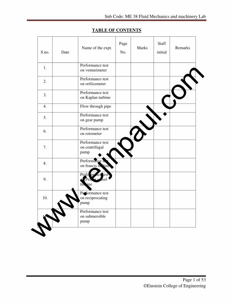
TABLE OF CONTENTS
S.no.
Date Name of the expt.
Page
No. Marks
Staff
initial
Remarks
1. Performance test
on venturimeter
2. Performance test
on orificemeter
3. Performance test
on Kaplan turbine
4. Flow through pipe
5. Performance test
on gear pump
6. Performance test
on rotometer
7.
Performance test
on centrifugal
pump
8. Performance test
on francis turbine
9.
Performance test
on Pelton wheel
turbine
10.
Performance test
on reciprocating
pump
11.
Performance test
on submersible
pump
www.rejin
paul.
com

Sub Code: ME 38 Fluid Mechanics and machinery Lab
Page 2 of 53
©Einstein College of Engineering
www.rejin
paul.
com
Sub Code: ME 38 Fluid Mechanics and machinery Lab
Page 3 of 53
©Einstein College of Engineering
Ex.No.1 FLOW THROUGH VENTURIMETER
Date:
AIM:
To determine the coefficient of discharge of the venturimeter.
APPARATUS REQUIRED:
A venturimeter, Differential U-Tube manometer, collecting tank fitted with piezometer
and control valve, stop watch and meter scale.
THEORY:
A venturimeter is one of the most important practical applications of Bernoulli’s theorem.
It is an instrument used to measure the rate of discharge in a pipe line and is often fixed
permanently at different sections of the pipe line to know the discharges there. A venturimeter
has been named after the 18th
century Italian ENGINEER VENTURI.
FORMULA USED:
1. Coefficient of discharge t
ad Q
QC = Where
Qa – actual discharge and Qt – theoretical discharge
2. Theoretical discharge 2
2
2
1
21 2
aa
ghaaQt
−= in m
3/sec
Where, 1a is the area of inlet in m2
2a is the area of outlet in m
2
h is the differential head in meter of water
g is the acceleration due to gravity m/sec2
2
114
daπ
= , where 1d = diameter of the inlet (m)
2
224
daπ
= , where 2d = diameter of outlet (m)
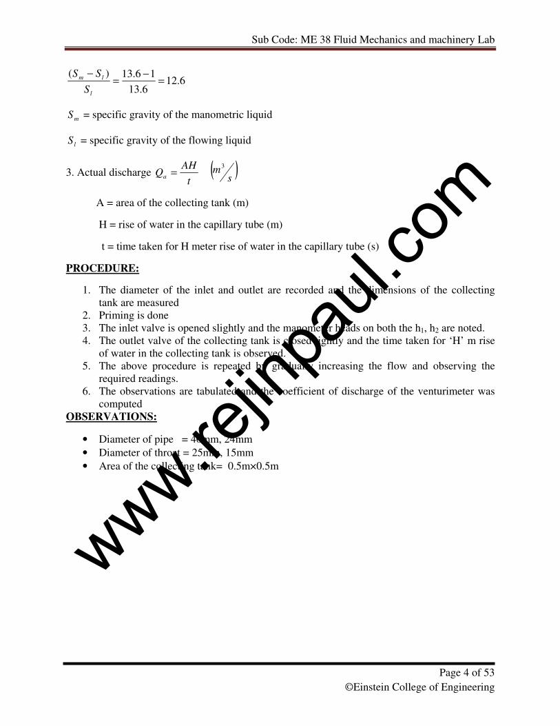
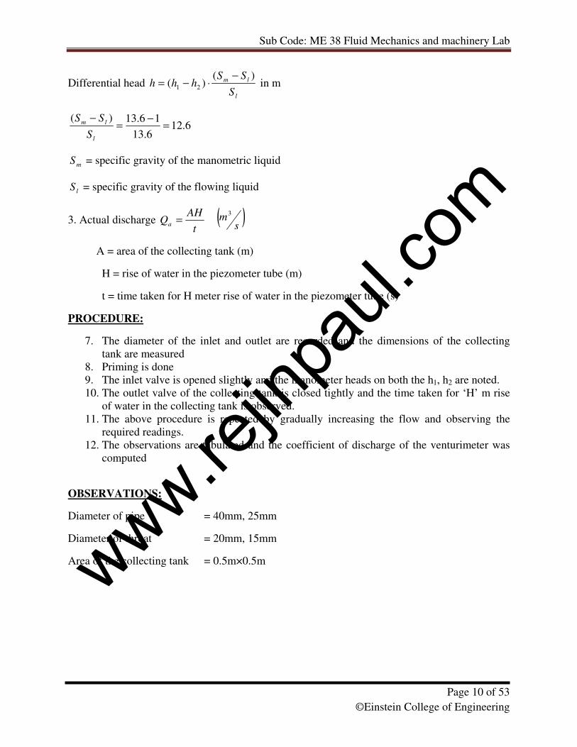
Differential head l
lm
S
SShhh
)()( 21
−⋅−= in m
www.rejin
paul.
com
Sub Code: ME 38 Fluid Mechanics and machinery Lab
Page 4 of 53
©Einstein College of Engineering
6.126.13
16.13)(=
−=
−
l
lm
S
SS
mS = specific gravity of the manometric liquid
lS = specific gravity of the flowing liquid
3. Actual discharge t
AHQa = ( )
sm
3
A = area of the collecting tank (m)
H = rise of water in the capillary tube (m)
t = time taken for H meter rise of water in the capillary tube (s)
PROCEDURE:
1. The diameter of the inlet and outlet are recorded and the dimensions of the collecting
tank are measured
2. Priming is done
3. The inlet valve is opened slightly and the manometer heads on both the h1, h2 are noted.
4. The outlet valve of the collecting tank is closed tightly and the time taken for ‘H’ m rise
of water in the collecting tank is observed.
5. The above procedure is repeated by gradually increasing the flow and observing the
required readings.
6. The observations are tabulated and the coefficient of discharge of the venturimeter was
computed
OBSERVATIONS:
• Diameter of pipe = 40mm, 24mm
• Diameter of throat = 25mm, 15mm
• Area of the collecting tank= 0.5m×0.5m
www.rejin
paul.
com
Sub Code: ME 38 Fluid Mechanics and machinery Lab
Page 5 of 53
©Einstein College of Engineering
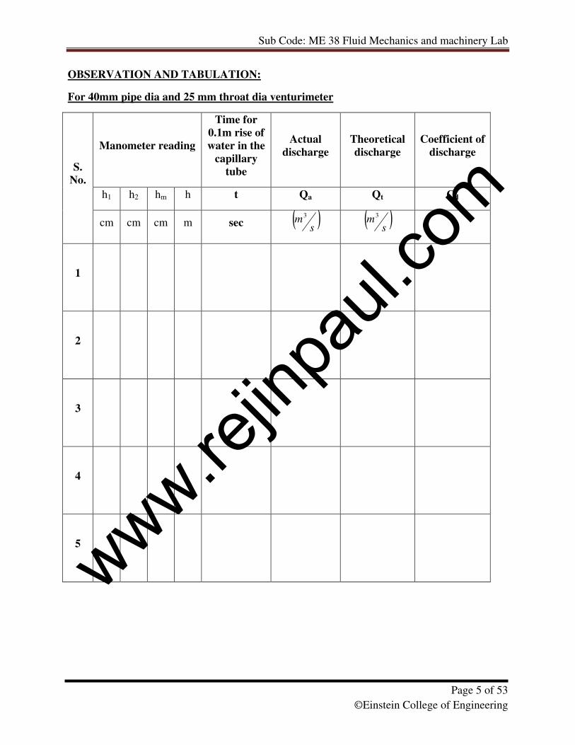
OBSERVATION AND TABULATION:
For 40mm pipe dia and 25 mm throat dia venturimeter
Manometer reading
Time for
0.1m rise of
water in the
capillary
tube
Actual
discharge
Theoretical
discharge
Coefficient of
discharge
h1 h2 hm h t Qa Qt Cd
S.
No.
cm cm cm m sec ( )s
m3
( )s
m3
1
2
3
4
5
www.rejin
paul.
com

Sub Code: ME 38 Fluid Mechanics and machinery Lab
Page 6 of 53
©Einstein College of Engineering
For 24mm pipe dia and 15 mm throat dia venturimeter
Manometer reading
Time for
0.1m rise of
water in the
capillary
tube
Actual
discharge
Theoretical
discharge
Coefficient of
discharge
h1 h2 hm h t Qa Qt Cd
S.
No.
cm cm cm m sec ( )s
m3
( )s
m3
1
2
3
4
5
www.rejin
paul.
com
Sub Code: ME 38 Fluid Mechanics and machinery Lab
Page 7 of 53
©Einstein College of Engineering
GRAPH:
• Actual discharge (Qa) Vs head (h)
Answer the following:
1. What is peizometer?
2. Define the following terms.
� Fluid.
� Specific volume
� Specific gravity.
� Viscosity.
� Compressibility.
� Vapour pressure.
� Capillarity.
� Surface tension.
3. Differentiate the following terms.
o Fluid and solid.
o Newtonian and non Newtonian fluid.
o Ideal and real fluid.
4. Derive continuity equation for compressible and incompressible fluid.
5. Differentiate between Absolute and gauge pressures
RESULT:
Thus the coefficient of discharge of venturimeter is determined.
www.rejin
paul.
com
Sub Code: ME 38 Fluid Mechanics and machinery Lab
Page 8 of 53
©Einstein College of Engineering
www.rejin
paul.
com
Sub Code: ME 38 Fluid Mechanics and machinery Lab
Page 9 of 53
©Einstein College of Engineering
Ex.No.2 FLOW THROUGH ORIFICEMETER
Date:
AIM:
To determine the coefficient of discharge of the orificemeter.
APPARATUS REQUIRED:
Orificemeter, Differential U-Tube manometer, collecting tank fitted with piezometer and
control valve, stop watch and meter scale.
THEORY:
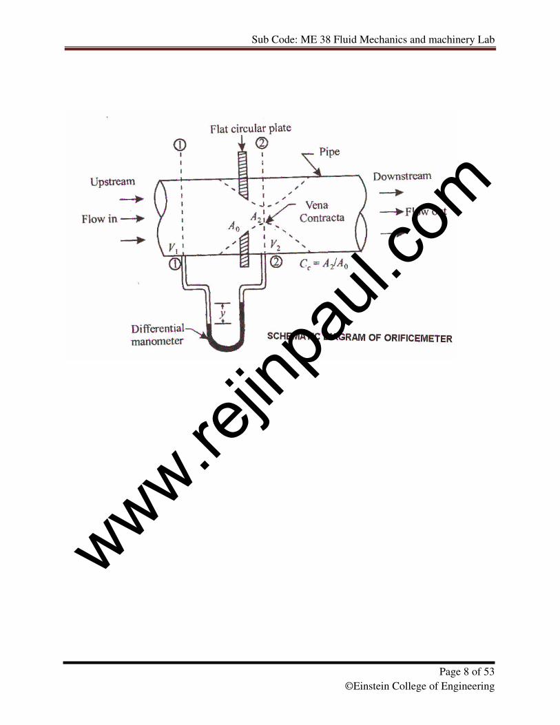
An orifice is an opening in the wall or base of a vessel through which the fluid flows. The
top edge of the orifice is always below the free surface. Orifices are used to measure the
discharge. An orifice is termed small when its dimensions are small compared to the head
causing flow. The variation in the velocity from the top to the bottom edge is considerable.
According to shape there are circular orifices, rectangular orifices, square orifices, Triangular
orifices.
FORMULA USED:
1. Coefficient of discharge t
ad Q
QC =
Where Qa – actual discharge and Qt – theoretical discharge
2. Theoretical discharge 2
2
2
1
21 2
aa
ghaaQt
−= in m
3/sec
where 1a is the area of inlet in m2
2a is the area of outlet in m
2
h is the differential head in meter of water
g is the acceleration due to gravity m/sec2
2
114
daπ
= , where 1d = diameter of the inlet (m)
2
224
daπ
= , where 2d = diameter of outlet (m)
www.rejin
paul.
com
Sub Code: ME 38 Fluid Mechanics and machinery Lab
Page 10 of 53
©Einstein College of Engineering
Differential head l
lm
S
SShhh
)()( 21
−⋅−= in m
6.126.13
16.13)(=
−=
−
l
lm
S
SS
mS = specific gravity of the manometric liquid
lS = specific gravity of the flowing liquid
3. Actual discharge t
AHQa = ( )
sm
3
A = area of the collecting tank (m)
H = rise of water in the piezometer tube (m)
t = time taken for H meter rise of water in the piezometer tube (s)
PROCEDURE:
7. The diameter of the inlet and outlet are recorded and the dimensions of the collecting
tank are measured
8. Priming is done
9. The inlet valve is opened slightly and the manometer heads on both the h1, h2 are noted.
10. The outlet valve of the collecting tank is closed tightly and the time taken for ‘H’ m rise
of water in the collecting tank is observed.
11. The above procedure is repeated by gradually increasing the flow and observing the
required readings.
12. The observations are tabulated and the coefficient of discharge of the venturimeter was
computed
OBSERVATIONS:
Diameter of pipe = 40mm, 25mm
Diameter of throat = 20mm, 15mm
Area of the collecting tank = 0.5m×0.5m
www.rejin
paul.
com
Sub Code: ME 38 Fluid Mechanics and machinery Lab
Page 11 of 53
©Einstein College of Engineering
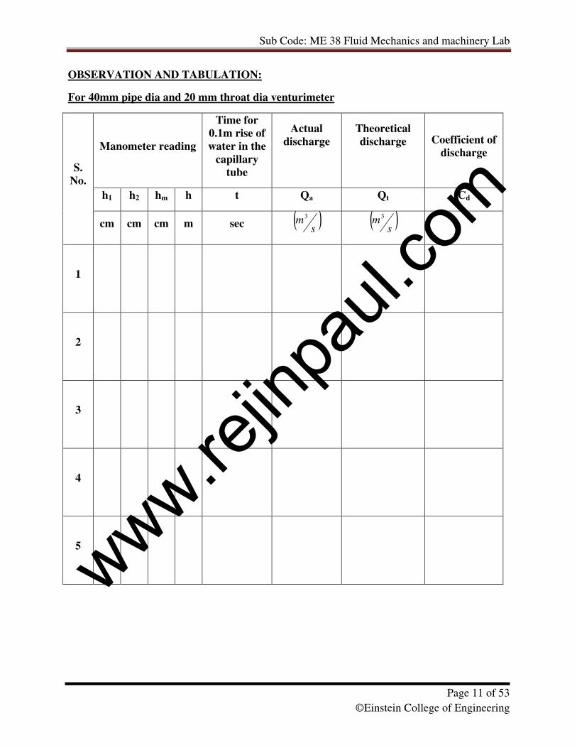
OBSERVATION AND TABULATION:
For 40mm pipe dia and 20 mm throat dia venturimeter
Manometer reading
Time for
0.1m rise of
water in the
capillary
tube
Actual
discharge
Theoretical
discharge
Coefficient of
discharge
h1 h2 hm h t Qa Qt Cd
S.
No.
cm cm cm m sec ( )s
m3
( )s
m3
1
2
3
4
5
www.rejin
paul.
com
Sub Code: ME 38 Fluid Mechanics and machinery Lab
Page 12 of 53
©Einstein College of Engineering
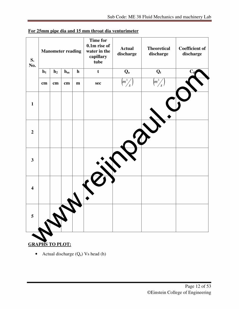
For 25mm pipe dia and 15 mm throat dia venturimeter
Manometer reading
Time for
0.1m rise of
water in the
capillary
tube
Actual
discharge
Theoretical
discharge
Coefficient of
discharge
h1 h2 hm h t Qa Qt Cd
S.
No.
cm cm cm m sec ( )s
m3
( )s
m3
1
2
3
4
5
GRAPHS TO PLOT:
• Actual discharge (Qa) Vs head (h)
www.rejin
paul.
com
Sub Code: ME 38 Fluid Mechanics and machinery Lab
Page 13 of 53
©Einstein College of Engineering
Answer the following:
1. Mention two pressure measuring instruments
2. How manometers are classified
3. State Newton’s law of viscosity
4. Define stream line.
5. Define path line.
RESULT:
Thus, the coefficient of discharge of orificemeter is determined.
www.rejin
paul.
com
Sub Code: ME 38 Fluid Mechanics and machinery Lab
Page 14 of 53
©Einstein College of Engineering
www.rejin
paul.
com
Sub Code: ME 38 Fluid Mechanics and machinery Lab
Page 15 of 53
©Einstein College of Engineering
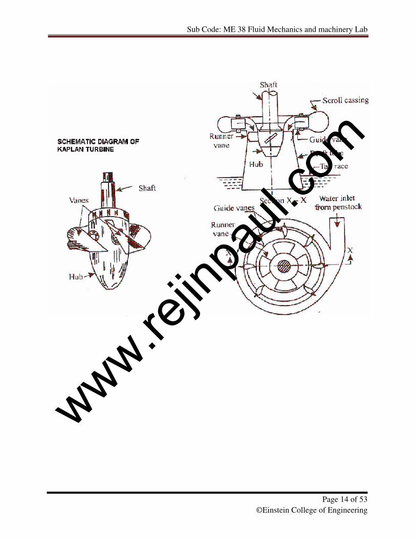
Ex.No. 3 PERFORMANCE TEST ON KAPLAN TURBINE
Date:
AIM:
To conduct the performance test on the Kaplan turbine.
APPARATUS REQUIRED:
i)Kaplan turbine
ii)Tachometer
THEORY:
Kaplan turbine is one of the types of axial flow turbine. Usually, it has 4 to 6 blades
having no outside rim. It is also known as variable pitch propeller turbine. The Kaplan turbine
behaves as a propeller turbine at full load conditions. In Kaplan turbine runner blades are
adjustable and can be rotated about pivots fixed to the boss of the runner. The blades are adjusted
automatically by servo mechanism so that at all loads the flow enters them without shock. Thus,
a high efficiency is maintained even at part load.
OBSERVATIONS:
• Rated supply head = 8m
• Discharge = 2500 lpm
• Rated speed = 1200 Rpm
• Runner outside diameter= 140mm
• Hub diameter = 70mm
• Hub ratio = 0.5
• No of runner blades = 4
• No of guide vanes = 12
• Brake drum diameter = 300mm
• Diameter of the pipe (d1) = 0.13m
• Diameter of the throat of venturimeter (d2) = 0.078 m
FORMULAE:
1. Rate of flow of water (Q) = [(a1× a2) ×� (2gh)] / [� (a12-a2
2) × 0.9]
in m
3/sec
• a1=area of inlet of the venturimeter= (� × d12)/ 4
• a2=area of throat of venturimeter= (� × d22)/ 4
• h=[(Sm/Sl)-1]×(h1-h2) in m
Sm- Specific gravity of mercury=13.6
Sl - Specific gravity of water=1
www.rejin
paul.
com
Sub Code: ME 38 Fluid Mechanics and machinery Lab
Page 16 of 53
©Einstein College of Engineering
2. Output power = 2�NT/60 Watts
• N is speed in rpm
• T is torque in Nm = radius of drum x (T1-T2)x g
3. Input power = �Qgh/1000 kw
4. Efficiency = (Output power P0/Input power Pi) x100
PROCEDURE:
1. Open the gate valve slowly and make it as fully open.
2. Now at full open and at no load, note the reading of manometer, pressure
Gauge.
3. Then, load the turbine by adjusting the screw rod connected to the belt which
Is on the brake drum and tighten the lock and the speed get reduced.
4. Now, note the readings of manometer, pressure gauge and spring balance.
5. Thus, for various loads with gate valve fully opened note the above said
Readings.
www.rejin
paul.
com
Sub Code: ME 38 Fluid Mechanics and machinery Lab
Page 17 of 53
©Einstein College of Engineering
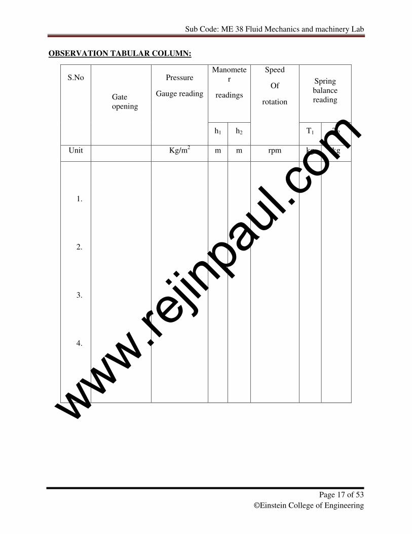
OBSERVATION TABULAR COLUMN:
Manomete
r
readings
Spring
balance
reading
S.No
Gate
opening
Pressure
Gauge reading
h1 h2
Speed
Of
rotation
T1 T2
Unit Kg/m2 m m rpm kg kg
1.
2.
3.
4.
www.rejin
paul.
com
Sub Code: ME 38 Fluid Mechanics and machinery Lab
Page 18 of 53
©Einstein College of Engineering
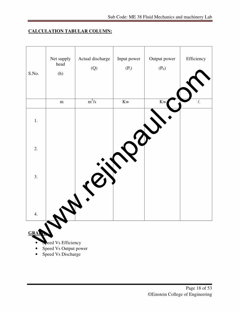
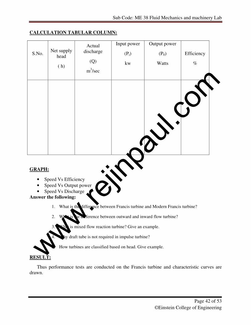
CALCULATION TABULAR COLUMN:
GRAPH:
• Speed Vs Efficiency
• Speed Vs Output power
• Speed Vs Discharge
S.No.
Net supply
head
(h)
Actual discharge
(Q)
Input power
(Pi)
Output power
(P0)
Efficiency
m m3/s Kw Kw
. /.
1.
2.
3.
4.
www.rejin
paul.
com
Sub Code: ME 38 Fluid Mechanics and machinery Lab
Page 19 of 53
©Einstein College of Engineering
Answer the following:
1. What is the difference between propeller and Kaplan turbine?
2. Mention the parts of Kaplan turbine.
3. Differentiate between inward and outward flow reaction turbine.
4. Define impulse turbine.
5. Define reaction turbine
RESULT:
Thus performance tests are conducted on the Kaplan turbine and characteristics curves are
drawn.
www.rejin
paul.
com
Sub Code: ME 38 Fluid Mechanics and machinery Lab
Page 20 of 53
©Einstein College of Engineering
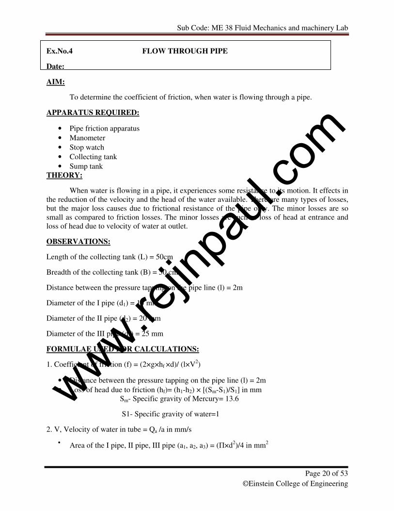
Ex.No.4 FLOW THROUGH PIPE
Date:
AIM:
To determine the coefficient of friction, when water is flowing through a pipe.
APPARATUS REQUIRED:
• Pipe friction apparatus
• Manometer
• Stop watch
• Collecting tank
• Sump tank
THEORY:
When water is flowing in a pipe, it experiences some resistance to its motion. It effects in
the reduction of the velocity and the head of the water available. There are many types of losses,
but the major loss causes due to frictional resistance of the pipe only. The minor losses are so
small as compared to friction losses. The minor losses are such as loss of head at entrance and
loss of head due to velocity of water at outlet.
OBSERVATIONS:
Length of the collecting tank (L) = 50cm
Breadth of the collecting tank (B) = 50 cm
Distance between the pressure tapping on the pipe line (l) = 2m
Diameter of the I pipe (d1) = 15 mm
Diameter of the II pipe (d2) = 20 mm
Diameter of the III pipe (d3) = 25 mm
FORMULAE USED FOR CALCULATIONS:
1. Coefficient of friction (f) = (2×g×hf ×d)/ (l×V2)
• Distance between the pressure tapping on the pipe line (l) = 2m
• Loss of head due to friction (hf)= (h1-h2) × [(Sm-S1)/S1] in mm
Sm- Specific gravity of Mercury= 13.6
S1- Specific gravity of water=1
2. V, Velocity of water in tube = Qa /a in mm/s
• Area of the I pipe, II pipe, III pipe (a1, a2, a3) = (�×d2)/4 in mm
2
www.rejin
paul.
com
Sub Code: ME 38 Fluid Mechanics and machinery Lab
Page 21 of 53
©Einstein College of Engineering
3. Actual discharge (Qa) = (A×H)/t in mm3/sec
• A (area of the collecting tank) = L × B in m2
• H= Height of water in collecting tank
• t = time taken for collection for H rise in the collecting tank. (In sec).
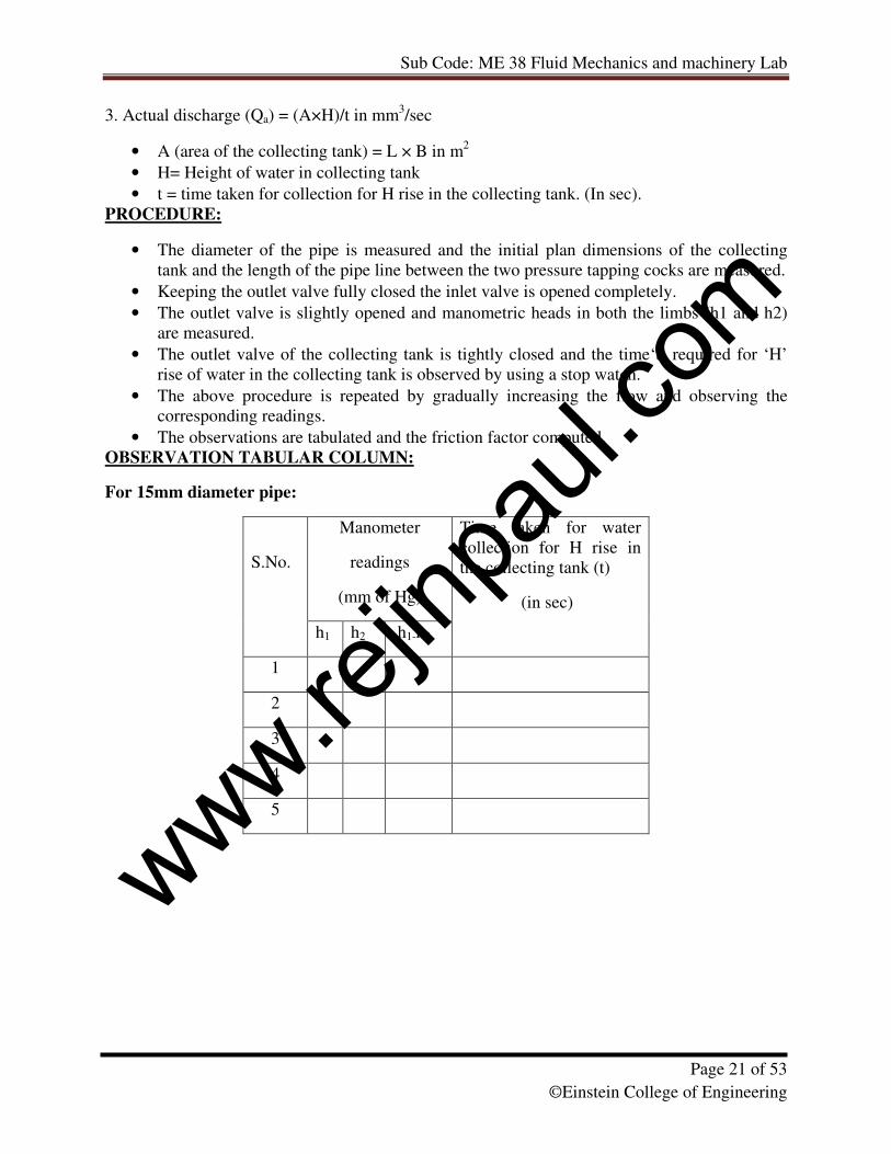
PROCEDURE:
• The diameter of the pipe is measured and the initial plan dimensions of the collecting
tank and the length of the pipe line between the two pressure tapping cocks are measured.
• Keeping the outlet valve fully closed the inlet valve is opened completely.
• The outlet valve is slightly opened and manometric heads in both the limbs (h1 and h2)
are measured.
• The outlet valve of the collecting tank is tightly closed and the time‘t’ required for ‘H’
rise of water in the collecting tank is observed by using a stop watch.
• The above procedure is repeated by gradually increasing the flow and observing the
corresponding readings.
• The observations are tabulated and the friction factor computed.
OBSERVATION TABULAR COLUMN:
For 15mm diameter pipe:
Manometer
readings
(mm of Hg)
S.No.
h1 h2 h1-h2
Time taken for water
collection for H rise in
the collecting tank (t)
(in sec)
1
2
3
4
5
www.rejin
paul.
com
Sub Code: ME 38 Fluid Mechanics and machinery Lab
Page 22 of 53
©Einstein College of Engineering
For 20mm diameter pipe:
Manometer
readings
(mm of Hg)
S.No.
h1 h2 h1-h2
Time taken for water
collection for H rise in
the collecting tank (t)
(in sec)
1
2
3
4
5
6
www.rejin
paul.
com
Sub Code: ME 38 Fluid Mechanics and machinery Lab
Page 23 of 53
©Einstein College of Engineering
CALCULATION TABULAR COLUMN: (For 15mm diameter pipe)
Mean Value of ‘f’=
S.No. Loss of head
hf =
(h1-h2) × [(Sm-S1)/S1]
in mm
Actual discharge
(Qa) = (A×H)/t
in mm3/sec
Velocity of
water in tube
= Qa /a
in mm/s
(V)
V2
(mm/s)2
Friction factor
f =
(2×g×hf×d)/
(l×V2)
www.rejin
paul.
com
Sub Code: ME 38 Fluid Mechanics and machinery Lab
Page 24 of 53
©Einstein College of Engineering
For 20mm diameter pipe:
Mean Value of ‘f’=
S.No. Loss of head
hf =
(h1-h2) × [(Sm-S1)/S1]
in mm
Actual discharge
(Qa) = (A×H)/t
in mm3/sec
Velocity of
water in tube =
Qa /a
in mm/s
(V)
V2
(mm/s)2
Friction factor
f =
(2×g×hf×d)/
(l×V2)
www.rejin
paul.
com
Sub Code: ME 38 Fluid Mechanics and machinery Lab
Page 25 of 53
©Einstein College of Engineering
GRAPHS TO PLOT:
‘h’ Vs ‘V2’
Answer the following:
1. What do you mean by major energy loss?
2. List down the type of minor energy losses.
3. What is compound pipe?
4. What do you mean by equivalent pipe
5. Derive Darcy -weisback's equation.
RESULT:
Thus, the coefficient of friction of the two pipes 20mm and 15mm determined and the
values are given below
Coefficient of friction (f) for 15mm diameter pipe =
Coefficient of friction (f) for 20mm diameter pipe =
www.rejin
paul.
com
Sub Code: ME 38 Fluid Mechanics and machinery Lab
Page 26 of 53
©Einstein College of Engineering
Ex.No:5 PERFORMANCE TEST ON GEAR PUMP
Date:
AIM:
To conduct a performance test on gear pump.
APPARATUS REQUIRED:
1. Gear Pump test rig
2. Stopwatch
3. Meter Scale
4. Plumb Bob
THEORY:
The gear pump test rig consisting of a gear pump coupled to an induction motor through
flexible coupling. The pump is mounted on an oil sump and a suction pipe with suction gauge,
delivery pipe with delivery gauge, discharge control valve etc provided. This being a positive
displacement pumps full closing of the delivery control valve should be avoided.
A collecting tank with gauge glass and scale fittings with drain valve fittings provided to
measure the pump discharge and to drain back the oil to the sump.
A panel with switch, starter and energy meter provided to note the input power. The gear
pump consists of two identical intermeshing spur wheels working with a fine clearance inside the
casing. The wheels are so designed that they form a fluid tight joint at the point of contact. One o
the wheels is keyed to the driving shaft and the other revolves as a driven wheel.
The pump is first filled with the liquid before it is started, as the gear rotate; the liquid is
trapped in between their teeth and is flown to the discharge end round the casing. The rotating
gears build up sufficient pressure to force the liquid into the delivery pipe. Each tooth of gear
acts like a piston of a reciprocating pump to force liquid into the discharge line.
FORMULA:
1. Area of the collecting tank (A) = l× b
l =40 cm
b= 40 cm
Energy meter constant (Ne) = 100 rev/Kw-hr
Datum level difference (x) = 0.3m
2. Actual discharge (Qa) = Ah/t
www.rejin
paul.
com
Sub Code: ME 38 Fluid Mechanics and machinery Lab
Page 27 of 53
©Einstein College of Engineering
• h- 10cm rise of oil level
• t- time taken for 10cm rise of oil level in collecting tank in seconds
3. Total head (H) = Hs+Hd+x
4. Input power (Pi) = [(3600 × Nr) / ( Ne× t)] × 1000 watt
• Nr – No. of revolutions of energy meter disc= 10
• t- Time taken for 10 revolutions of energy meter disc.
5. Output power (P0) = (�oil ×g× Qa× H)/ 1000 Kw
�oil = 850 Kg/ m3
6. Efficiency of the pump = P0 / Pi in %
1 Kg/ Cm2 = 12 m of oil column
PROCEDURE:
1. Prime the pump if necessary, open the delivery valve and switch on the unit.
2. Close the delivery valve and maintain required delivery head. Note the reading.
3. Note the corresponding suction head.
4. Measure the area of the collecting tank.
5. Close the drain valve and note the time for 10 cm rise of oil level in the collecting
tank.
6. For different delivery head repeat the experiment.
7. For every set of reading note the time taken for 10 Rev. energy meter.
www.rejin
paul.
com
Sub Code: ME 38 Fluid Mechanics and machinery Lab
Page 28 of 53
©Einstein College of Engineering
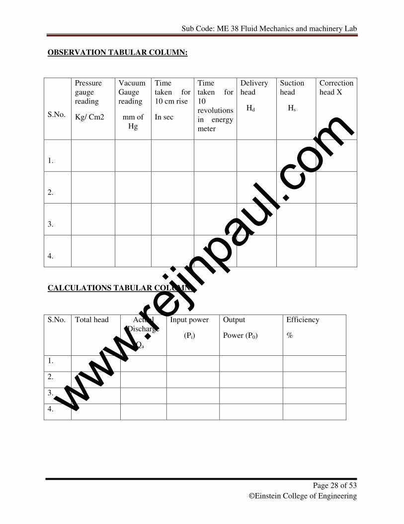
OBSERVATION TABULAR COLUMN:
CALCULATIONS TABULAR COLUMN:
S.No. Total head Actual
Discharge
Qa
Input power
(Pi)
Output
Power (P0)
Efficiency
%
1.
2.
3.
4.
S.No.
Pressure
gauge
reading
Kg/ Cm2
Vacuum
Gauge
reading
mm of
Hg
Time
taken for
10 cm rise
In sec
Time
taken for
10
revolutions
in energy
meter
Delivery
head
Hd
Suction
head
Hs
Correction
head X
1.
2.
3.
4.
www.rejin
paul.
com
Sub Code: ME 38 Fluid Mechanics and machinery Lab
Page 29 of 53
©Einstein College of Engineering
GRAPHS TO PLOT:
Plot graphs for
Discharge Vs Total Head
Output Power Vs Total Head
Efficiency Vs Total Head
Answer the following:
1. Briefly explain Gear pump.
2. Differentiate between internal gear pump and external gear pump.
3. Briefly explain vane pump.
4. What is rotary pump?
5. How performance characteristic curves are drawn for pump
RESULT:
Maximum Efficiency of the pump = ……………………..
Total head of maximum Efficiency = ……………………
www.rejin
paul.
com
Sub Code: ME 38 Fluid Mechanics and machinery Lab
Page 30 of 53
©Einstein College of Engineering
www.rejin
paul.
com
Sub Code: ME 38 Fluid Mechanics and machinery Lab
Page 31 of 53
©Einstein College of Engineering
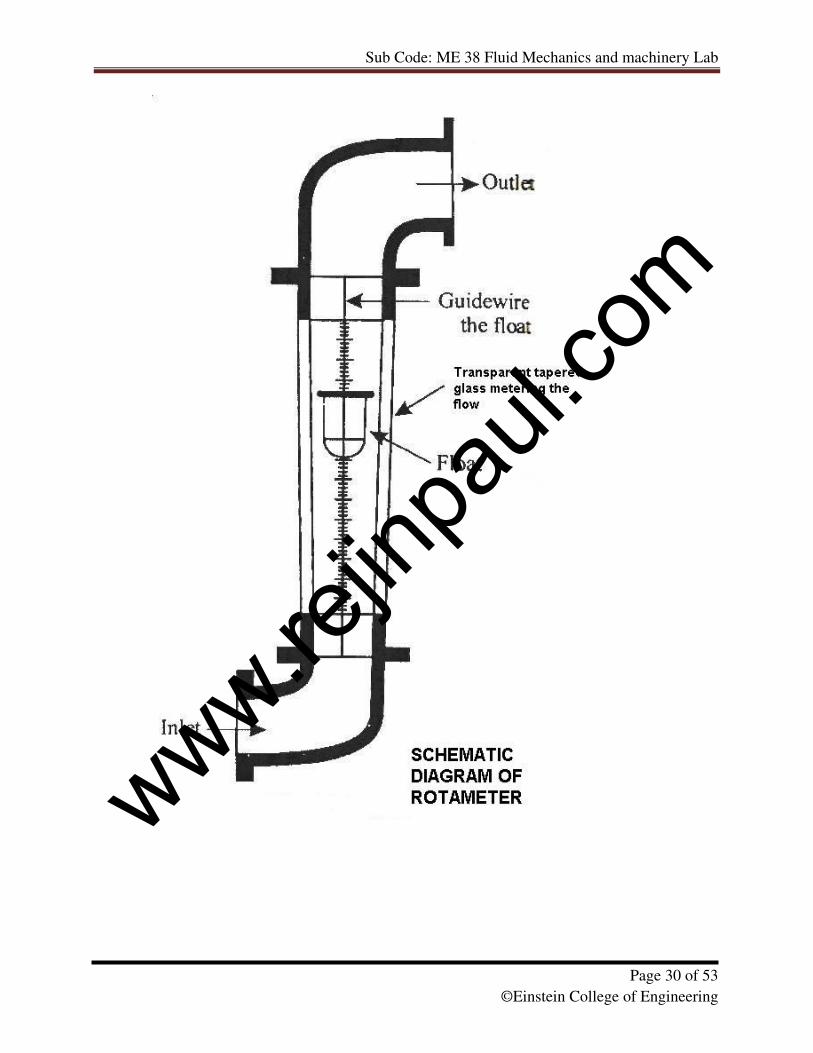
Ex.No. 6 PERFORMANCE TEST ON ROTAMETER
Date:
AIM:
To determine the coefficient of discharge of the rotometer.
APPARATUS REQUIRED:
A rotometer having 0 – 30LPM range, single phase 0.5 HP 1440 rpm
monoblock pump, reservoir tank arrangement, piping system, stopwatch and meter scale.
THEORY:
When the rate of flow increases the float rises in the tube and consequently there is an increase in
the annular area between the float and the tube. Thus, the float rides higher or lower dephending
on the rate of flow.
FORMULA USED:
1.Actual discharge 000,60×=t
AHQa LPM
A = area of the collecting tank (m)
H = rise of water in the capillary tube (m)
t = time taken for H meter rise of water in the capillary tube (s)
2. Coefficient of discharge R
ad Q
QC =
Qa – actual discharge (LPM) and QR – Rotometer discharge (LPM)
PROCEDURE:
1. Priming is done first for venting air from the pipes.
2. The inlet valve is opened slightly such that the discharge on the rotometer is noted.
3. The outlet valve of the collecting tank is closed tightly and the time taken for ‘H’ meter
rise of water in the collecting tank is observed.
4. The above procedure is repeated by gradually increasing the flow and observing the
required readings.
5. The observations are tabulated and the coefficient of discharge of rotometer is compared.
www.rejin
paul.
com
Sub Code: ME 38 Fluid Mechanics and machinery Lab
Page 32 of 53
©Einstein College of Engineering
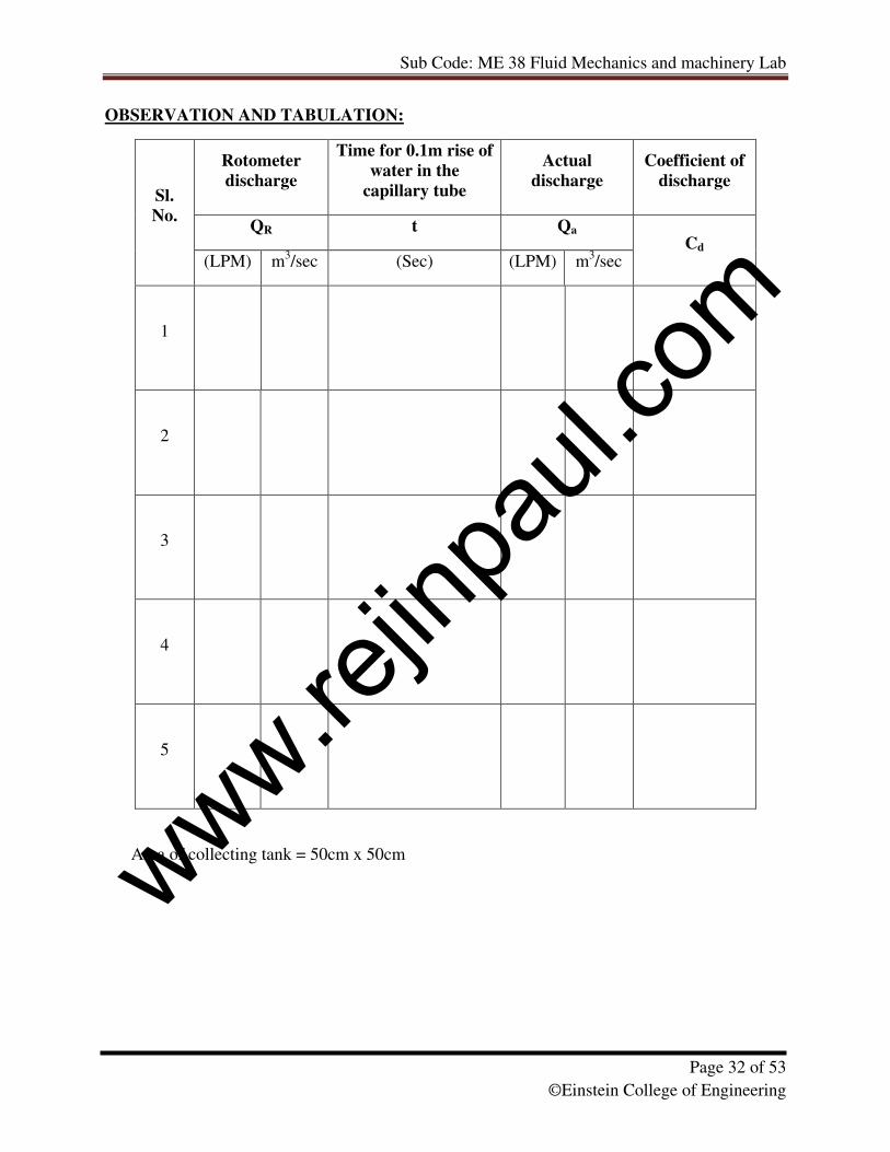
OBSERVATION AND TABULATION:
Rotometer
discharge
Time for 0.1m rise of
water in the
capillary tube
Actual
discharge
Coefficient of
discharge
QR t Qa
Sl.
No.
(LPM) m3/sec (Sec) (LPM) m
3/sec
Cd
1
2
3
4
5
Area of collecting tank = 50cm x 50cm
www.rejin
paul.
com
Sub Code: ME 38 Fluid Mechanics and machinery Lab
Page 33 of 53
©Einstein College of Engineering
Answer the following:
1. Mention few discharge measuring devices
2. Derive an expression for discharge in venturimeter
3. Derive an expression for discharge in orifice meter Write down Euler’s equation of
motion.
4. Write down Bernoulli’s equation of motion for ideal and real fluid
RESULT:
Thus, the coefficient of discharge (Cd) of rotometer is determined.
www.rejin
paul.
com
Sub Code: ME 38 Fluid Mechanics and machinery Lab
Page 34 of 53
©Einstein College of Engineering
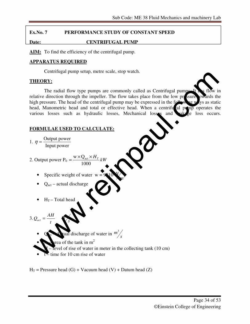
Ex.No. 7 PERFORMANCE STUDY OF CONSTANT SPEED
Date: CENTRIFUGAL PUMP
AIM: To find the efficiency of the centrifugal pump.
APPARATUS REQUIRED
Centrifugal pump setup, metre scale, stop watch.
THEORY:
The radial flow type pumps are commonly called as Centrifugal pumps. It has flow in
relative direction through the impeller. The flow takes place from the low pressure towards the
high pressure. The head of the centrifugal pump may be expressed in the following ways as static
head, Manometric head and total or effective head. When a centrifugal pump operates the
various losses such as hydraulic losses, Mechanical losses and leakage loss occurs.
FORMULAE USED TO CALCULATE:
1. powerInput
powerOutput =η
2. Output power P0 kWHT
1000
Qw act ××
=
• Specific weight of water w = 9810 3m
N
• Qact – actual discharge
• HT – Total head
3.t
AHQact =
sm
3
• Qact – Actual discharge of water in s
m3
• A – area of the tank in m2
• H – level of rise of water in meter in the collecting tank (10 cm)
• t – time for 10 cm rise of water
HT = Pressure head (G) + Vacuum head (V) + Datum head (Z)
www.rejin
paul.
com
Sub Code: ME 38 Fluid Mechanics and machinery Lab
Page 35 of 53
©Einstein College of Engineering
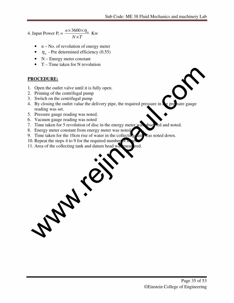
4. Input Power Pi = TN
n m
×
×× η3600 Kw
• n – No. of revolution of energy meter
• mη - Pre determined efficiency (0.55)
• N – Energy meter constant
• T – Time taken for N revolution
PROCEDURE:
1. Open the outlet valve until it is fully open.
2. Priming of the centrifugal pump
3. Switch on the centrifugal pump
4. By closing the outlet value the delivery pipe, the required pressure in the pressure gauge
reading was set.
5. Pressure gauge reading was noted.
6. Vacuum gauge reading was noted
7. Time taken for 5 revolution of disc in the energy meter was observed and noted.
8. Energy meter constant from energy meter was noted
9. Time taken for the 10cm rise of water in the collecting tank was noted down.
10. Repeat the steps 4 to 9 for the required number of times.
11. Area of the collecting tank and datum head was measured.
www.rejin
paul.
com
Sub Code: ME 38 Fluid Mechanics and machinery Lab
Page 36 of 53
©Einstein College of Engineering
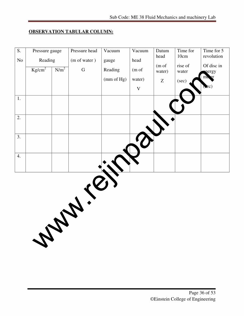
OBSERVATION TABULAR COLUMN:
Pressure gauge
Reading
S.
No
Kg/cm2 N/m
2
Pressure head
(m of water )
G
Vacuum
gauge
Reading
(mm of Hg)
Vacuum
head
(m of
water)
V
Datum
head
(m of
water)
Z
Time for
10cm
rise of
water
(sec)
Time for 5
revolution
Of disc in
energy
meter
(sec)
1.
2.
3.
4.
www.rejin
paul.
com
Sub Code: ME 38 Fluid Mechanics and machinery Lab
Page 37 of 53
©Einstein College of Engineering
CALCULATION TABULAR COLUMN:
S.No. Total Head
HT =
G+V+Z
Actual
Discharge
t
AHQact =
s
m3
Input power
Pi
Kw
Output
power
P0
Kw
Efficiency
P0 / Pi
1.
2.
3.
4.
5.
GRAPHS TO PLOT:
• Input power Vs Qact
• Efficiency Vs Qact
• Total head Vs Qact
• Output power Vs Qact
www.rejin
paul.
com
Sub Code: ME 38 Fluid Mechanics and machinery Lab
Page 38 of 53
©Einstein College of Engineering
Answer the following:
1. Define Positive displacement pump.
2. Differentiate between Roto-dynamic and positive displacement pump.
3. Define cavitation in pump.
4. What is the need for priming in pump?
5. Mention the type of casing used in centrifugal pump
RESULT:
Thus, the efficiency of the centrifugal pump has been determined by conducting the performance
test.
www.rejin
paul.
com
Sub Code: ME 38 Fluid Mechanics and machinery Lab
Page 39 of 53
©Einstein College of Engineering
www.rejin
paul.
com
Sub Code: ME 38 Fluid Mechanics and machinery Lab
Page 40 of 53
©Einstein College of Engineering
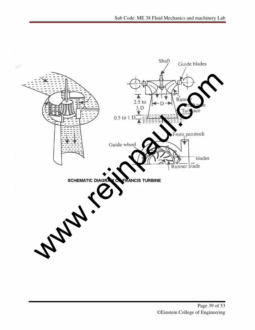
Ex.No. 8 PERFORMANCE TEST ON FRANCIS TURBINE
Date:
AIM:To conduct the performance test on Francis turbine.
APPARATUS REQUIRED:
i) Francis turbine setup
ii) Tachometer
THEORY:
The modern Francis Turbine is an inward mixed flow reaction turbine. Here the water
pressure enters the runner from the guide vanes towards the centre in radial direction and
discharges out of the runner axially. The Francis Turbine operates under medium heads and
requires medium quantity of water. Francis turbine has been installed in Bhakra nangal project,
Punjab across the river Sutlej River.
OBSERVATIONS:
• Rated supply head = 1.2m
• Discharge = 2000 lpm
• Rated speed = 1250 Rpm
• Runner diameter = 180mm
• Power output = 3HP
• No of guide vanes = 8
• Brake drum diameter = 300mm
• Diameter of the pipe (d1) = 0.13m
• Diameter of the throat of venturimeter (d2) = 0.078m
FORMULAE USED FOR CALCULATION:
1. Rate of flow of water (Q) = [(a1× a2) ×� (2gh)] / [� (a12-a2
2) × 0.9] in m
3/sec.
• a1=area of inlet of venturimeter= (� × d12)/ 4
• a2=area of throat of venturimeter = (� × d22)/ 4
2. h= [(Sm / Sl)-1)] × (h1-h2) in m
• Sm- Specific gravity of mercury=13.6
• Sl - Specific gravity of water=1
3. Output power (P0) = 2�NT/60 Watts
• N is speed in rpm
• T is torque in Nm = radius of drum x (T1-T2)x g
4. Input power (Pi) = (�w x Q x g x h)/1000 kw
5. Efficiency = (Output power (P0)/Input power (Pi)) x100
www.rejin
paul.
com
Sub Code: ME 38 Fluid Mechanics and machinery Lab
Page 41 of 53
©Einstein College of Engineering
PROCEDURE:
1. Open the gate valve slowly so that the turbine at 1200 Rpm (at no load).
2. Apply the load adjusting the screw rod connected to the belt for loading the
Brakes drum and tighten the locknut and the speed gets reduced.
3. Now note the readings of manometer, pressure gauge and spring balance.
4. Open the gate valve to an extent such that the speed is 1200 rpm.
5. Now note the manometer, pressure gauge readings and spring balance
Readings.
6. For various loads note the above said readings.
OBSERVATION TABULAR COLUMN:
Manometer
readings
Spring
balance
reading
S.No
Pressure
Gauge
reading
h1 h2
Speed
Of
rotation
(N) T1 T2
Unit Kg/cm2 cm cm rpm kg kg
1.
2.
3.
www.rejin
paul.
com
Sub Code: ME 38 Fluid Mechanics and machinery Lab
Page 42 of 53
©Einstein College of Engineering
CALCULATION TABULAR COLUMN:
GRAPH:
• Speed Vs Efficiency
• Speed Vs Output power
• Speed Vs Discharge
Answer the following:
1. What is the difference between Francis turbine and Modern Francis turbine?
2. What is the difference between outward and inward flow turbine?
3. What is mixed flow reaction turbine? Give an example.
4. Why draft tube is not required in impulse turbine?
5. How turbines are classified based on head. Give example.
RESULT:
Thus performance tests are conducted on the Francis turbine and characteristic curves are
drawn.
S.No. Net supply
head
( h)
Actual
discharge
(Q)
m3/sec
Input power
(Pi)
kw
Output power
(P0)
Watts
Efficiency
%
www.rejin
paul.
com
Sub Code: ME 38 Fluid Mechanics and machinery Lab
Page 43 of 53
©Einstein College of Engineering
www.rejin
paul.
com
Sub Code: ME 38 Fluid Mechanics and machinery Lab
Page 44 of 53
©Einstein College of Engineering
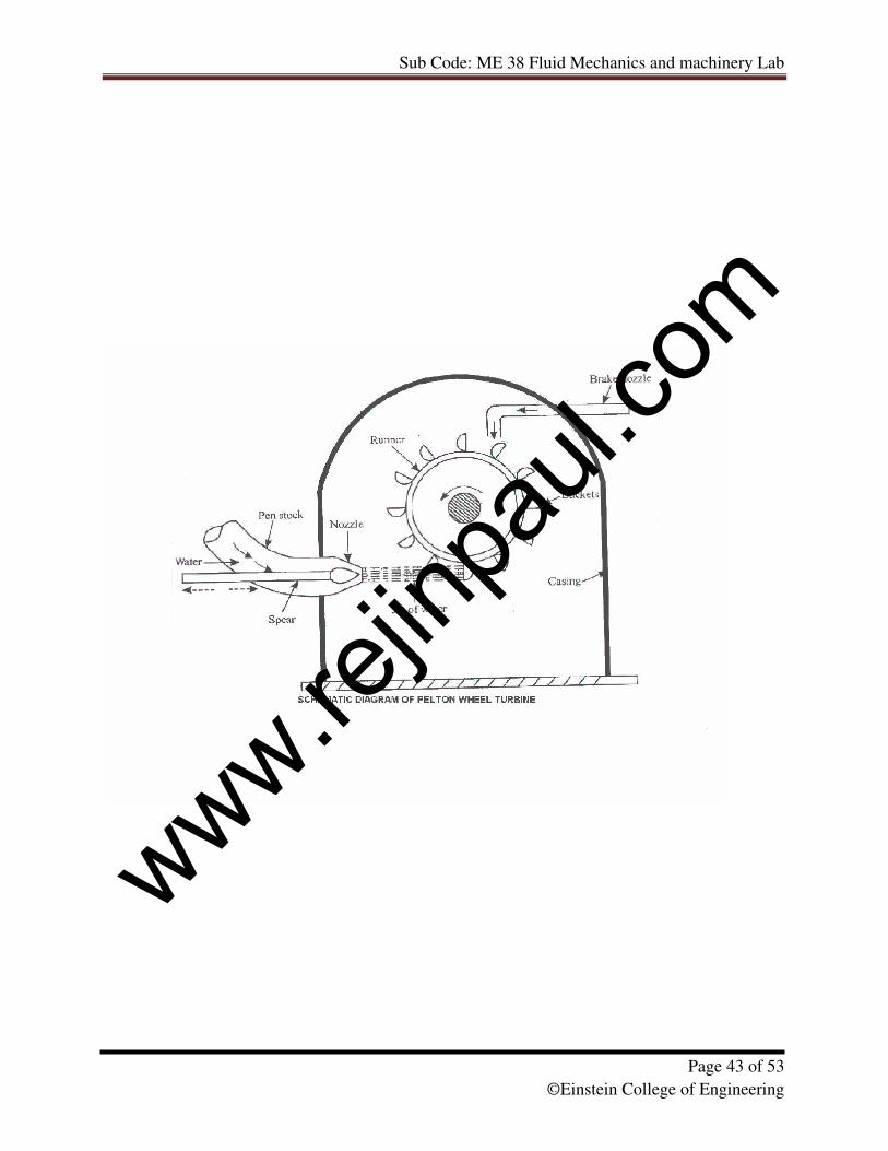
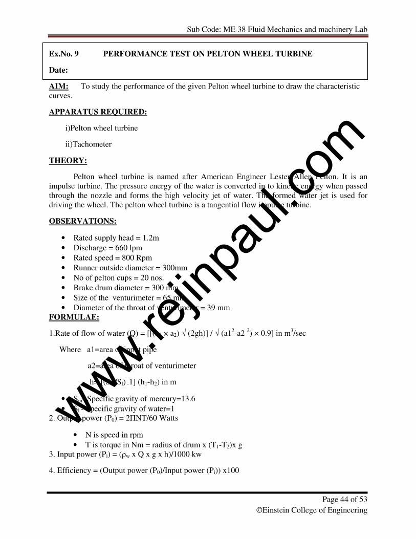
Ex.No. 9 PERFORMANCE TEST ON PELTON WHEEL TURBINE
Date:
AIM: To study the performance of the given Pelton wheel turbine to draw the characteristic
curves.
APPARATUS REQUIRED:
i)Pelton wheel turbine
ii)Tachometer
THEORY:
Pelton wheel turbine is named after American Engineer Lester Allen Pelton. It is an
impulse turbine. The pressure energy of the water is converted in to kinetic energy when passed
through the nozzle and forms the high velocity jet of water. The formed water jet is used for
driving the wheel. The pelton wheel turbine is a tangential flow impulse turbine.
OBSERVATIONS:
• Rated supply head = 1.2m
• Discharge = 660 lpm
• Rated speed = 800 Rpm
• Runner outside diameter = 300mm
• No of pelton cups = 20 nos.
• Brake drum diameter = 300 mm
• Size of the venturimeter = 65 mm
• Diameter of the throat of venturimeter = 39 mm
FORMULAE:
1.Rate of flow of water (Q) = [[(a1 × a2) � (2gh)] / � (a12-a2
2) × 0.9] in m
3/sec
Where a1=area of input pipe
a2=area of throat of venturimeter
h= [(Sm/Sl) -1] (h1-h2) in m
• Sm- Specific gravity of mercury=13.6
• Sl - Specific gravity of water=1
2. Output power (P0) = 2�NT/60 Watts
• N is speed in rpm
• T is torque in Nm = radius of drum x (T1-T2)x g
3. Input power (Pi) = (�w x Q x g x h)/1000 kw
4. Efficiency = (Output power (P0)/Input power (Pi)) x100
www.rejin
paul.
com
Sub Code: ME 38 Fluid Mechanics and machinery Lab
Page 45 of 53
©Einstein College of Engineering
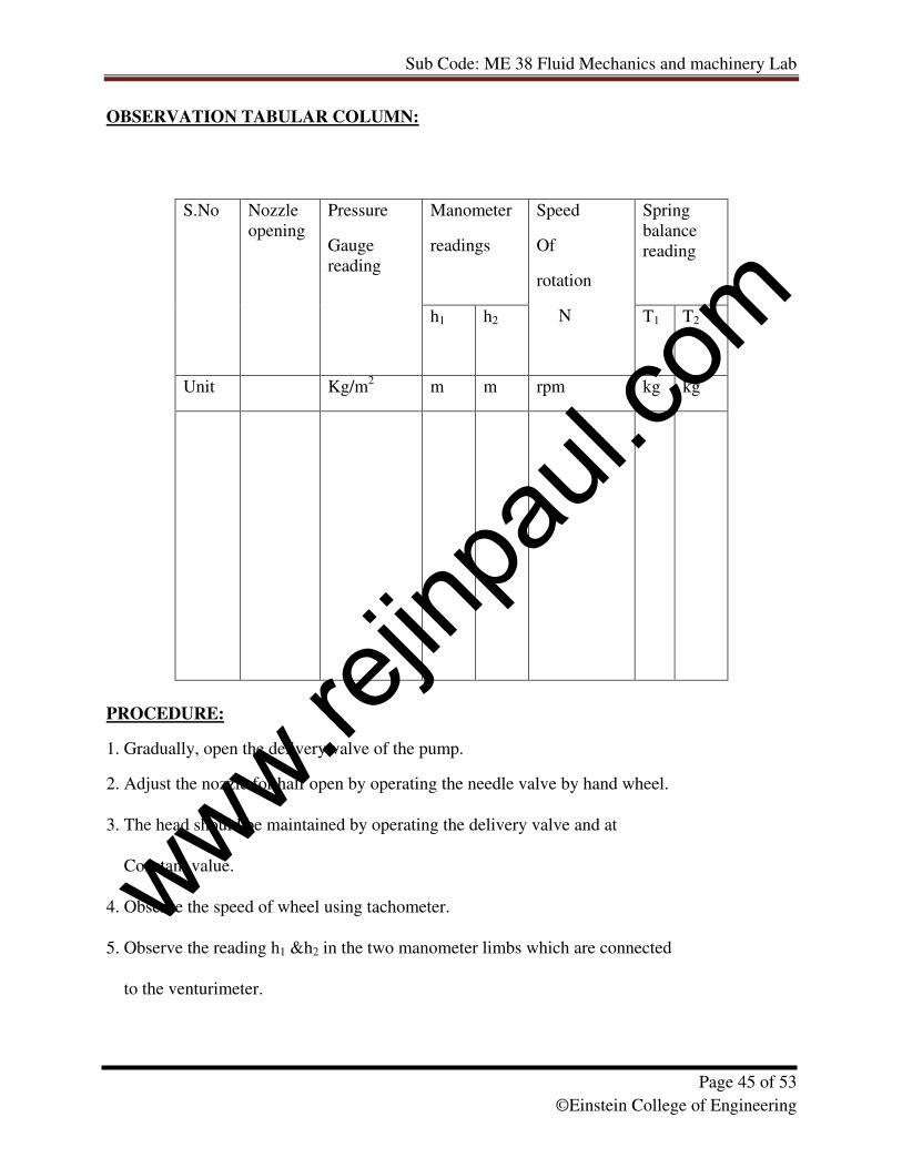
OBSERVATION TABULAR COLUMN:
PROCEDURE:
1. Gradually, open the delivery valve of the pump.
2. Adjust the nozzle for half open by operating the needle valve by hand wheel.
3. The head should be maintained by operating the delivery valve and at
Constant value.
4. Observe the speed of wheel using tachometer.
5. Observe the reading h1 &h2 in the two manometer limbs which are connected
to the venturimeter.
Manometer
readings
Spring
balance
reading
S.No
Nozzle
opening
Pressure
Gauge
reading
h1 h2
Speed
Of
rotation
N
T1 T2
Unit Kg/m2
m m rpm kg kg
www.rejin
paul.
com
Sub Code: ME 38 Fluid Mechanics and machinery Lab
Page 46 of 53
©Einstein College of Engineering
CALCULATION TABULAR COLUMN:
Net supply head
(h) in m
Actual discharge
(Q)
Input power
(Pi)
Output power
(P0)
Efficiency
m m3/s kw kw
. /.
GRAPH:
• Speed Vs Efficiency
• Speed Vs Output power
• Speed Vs Discharge
Answer the following:
1. What are the main parameters in designing a Pelton wheel turbine?
2. What is breaking jet in Pelton wheel turbine?
3. What is the function of casing in Pelton turbine
4. Draw a simple sketch of Pelton wheel bucket.
5. What is the function of surge tank fixed to penstock in Pelton turbine?
RESULT:
Thus performance tests are conducted on the Pelton wheel turbine and characteristic curves
are drawn.
www.rejin
paul.
com
Sub Code: ME 38 Fluid Mechanics and machinery Lab
Page 47 of 53
©Einstein College of Engineering
www.rejin
paul.
com
Sub Code: ME 38 Fluid Mechanics and machinery Lab
Page 48 of 53
©Einstein College of Engineering
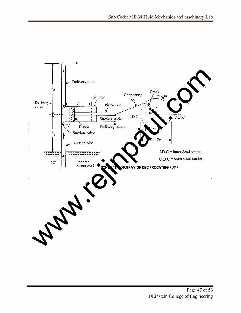
Ex.No.10 PERFORMANCE TEST IN RECIPROCATING PUMP
Date:
AIM:
To conduct performance test in a reciprocating pump.
APPARATUS REQUIRED:
• Reciprocating test rig
• Stop watch
• Meter scale
• Pump
THEORY:
Reciprocating pumps are also classified as positive displacement pumps. Here definite
volume of liquid is trapped in a chamber which is alternatively filled from the inlet and emptied
at a higher pressure through the discharge. Most piston pumps are acting with liquid admitted
alternatively on each side of the piston so that one part of the cylinder is being filled where as the
other being emptied to minimize fluctuations in the discharge.
OBSERVATIONS:
Energy meter constant (Ne) = 100 rev/ KW-hr
Stroke length of the pump (L) = 0.045m
Bore (d) = 0.04m
Area of the collecting tank (a) = 0.25 m2
FORMULAE USED FOR CALCULATION:
1. Piston area (A) = (�/4) × L2 in m
2
2. Percentage of slip= [(Qt - Qa)/ Qt] × 100 in%
3. Theoretical discharge (Qt) = (2 × L × A × N)/ 60 m3/sec
4. Actual discharge (Qa) = [(A×H)/ t] (in m3/sec)
t- Time taken for 10cm rise in water level.
H= suction head (hs) + Delivery head (hd) in meters of water.
5. Over all Efficiency (�O) = (P0/Pi) × 100 in %
6. Output power (P0) = (3600/ Ne) × (10/te) in Kw
7. Input power (Pi) = (� × g × Qa × H ) / 1000 in Kw
�- Density of water = 1000 Kg/ m3
www.rejin
paul.
com
Sub Code: ME 38 Fluid Mechanics and machinery Lab
Page 49 of 53
©Einstein College of Engineering
PROCEDURE:
a) Keep the delivery valve open and switch on the pump. Slowly close the delivery
valve and maintain a constant head.
b) Note the delivery and suction gauge reading.
c) Note the time for 10 rev of energy meter.
d) Note the time for 10cm rise in water level in the collecting tank.
e) Note the speed of the pump (N) Rpm.
f) Repeat the procedure for various openings of the delivery valve.
OBSERVATION TABULAR COLUMN:
S.No. Pressure
gauge
reading
( Kg/cm2)
Vacuum gauge
reading
(mm of Hg)
Time for
10 rev
in energy
meter (te)
(in sec)
Time
taken for
10cm rise
in water
level (t)
(in sec)
Delivery
head
(hd)
(in m)
Suction
Head
(hs)
(in m)
1.
2.
3.
4.
5.
www.rejin
paul.
com
Sub Code: ME 38 Fluid Mechanics and machinery Lab
Page 50 of 53
©Einstein College of Engineering
CALCULATION TABULAR COLUMN:
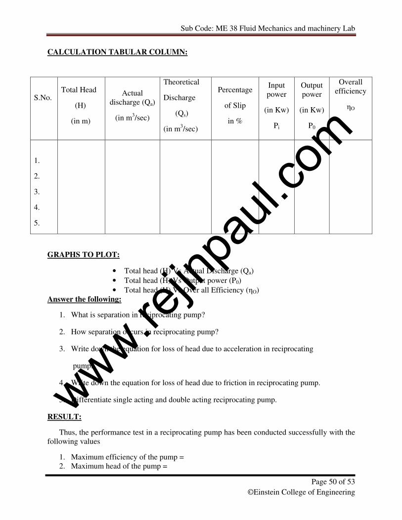
GRAPHS TO PLOT:
• Total head (H) Vs Actual Discharge (Qa)
• Total head (H) Vs Output power (P0)
• Total head (H) Vs Over all Efficiency (�O)
Answer the following:
1. What is separation in reciprocating pump?
2. How separation occurs in reciprocating pump?
3. Write down the equation for loss of head due to acceleration in reciprocating
pump.
4. Write down the equation for loss of head due to friction in reciprocating pump.
5. Differentiate single acting and double acting reciprocating pump.
RESULT:
Thus, the performance test in a reciprocating pump has been conducted successfully with the
following values
1. Maximum efficiency of the pump =
2. Maximum head of the pump =
S.No. Total Head
(H)
(in m)
Actual
discharge (Qa)
(in m3/sec)
Theoretical
Discharge
(Qs)
(in m3/sec)
Percentage
of Slip
in %
Input
power
(in Kw)
Pi
Output
power
(in Kw)
P0
Overall
efficiency
�O
1.
2.
3.
4.
5.
www.rejin
paul.
com
Sub Code: ME 38 Fluid Mechanics and machinery Lab
Page 51 of 53
©Einstein College of Engineering
Ex.No.11 PERFORMANCE TEST IN SUBMERSIBLE PUMP
Date:
AIM:
To conduct performance test in a submersible pump.
APPARATUS REQUIRED:
• SUBMERSIBLE PUMP test rig
• Stop watch
• Meter scale
• Plump bob
FORMULAE USED FOR CALCULATION:
1. Discharge, Q = a1 × a2 � (g × h) / � (a12- a2
2) in m
3/ sec.
a1= inlet area of venturimeter
a2= throat area of venturimeter
h = (h1-h2) × [(sm/sw) -1] in m
g is the acceleration due to gravity m/sec2
2
114
daπ
= , where 1d = diameter of the inlet (m)
2
224
daπ
= , where 2d = diameter of outlet (m)
mS = specific gravity of the manometric liquid = 13.6
lS = specific gravity of the flowing liquid = 1
2. Output power, Po = (� × g × Q × Hd)/ 1000 Kw
The total efficiency head H in meters of water column = Hd
(The delivery pressure is in Kg/ cm2; the total head developed in the pump has to be converted in
metres of water column).
3. Input power, Pi = (3600 × 10)/ (Ne × t) Kw
4. Efficiency of the pump = Po / Pi in %
www.rejin
paul.
com
Sub Code: ME 38 Fluid Mechanics and machinery Lab
Page 52 of 53
©Einstein College of Engineering
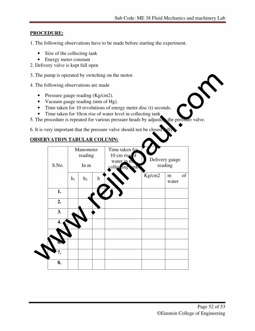
PROCEDURE:
1. The following observations have to be made before starting the experiment.
• Size of the collecting tank
• Energy meter constant
2. Delivery valve is kept full open
3. The pump is operated by switching on the motor.
4. The following observations are made
• Pressure gauge reading (Kg/cm2).
• Vacuum gauge reading (mm of Hg).
• Time taken for 10 revolutions of energy meter disc (t) seconds.
• Time taken for 10cm rise of water level in collecting tank.
5. The procedure is repeated for various pressure heads by adjusting the pressure valve.
6. It is very important that the pressure valve should not be closed fully.
OBSERVATION TABULAR COLUMN:
Manometer
reading
In m
Delivery gauge
reading S.No.
h1 h2 h
Time taken for
10 cm rise of
water in the
collecting tank
Kg/cm2 m of
water
1.
2.
3.
4.
5.
6.
7.
8.
www.rejin
paul.
com
Sub Code: ME 38 Fluid Mechanics and machinery Lab
Page 53 of 53
©Einstein College of Engineering
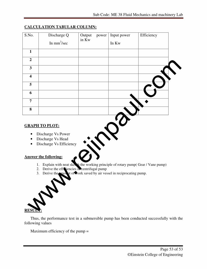
CALCULATION TABULAR COLUMN:
S.No. Discharge Q
In mm3/sec
Output power
in Kw
Input power
In Kw
Efficiency
1
2
3
4
5
6
7
8
GRAPH TO PLOT:
• Discharge Vs Power
• Discharge Vs Head
• Discharge Vs Efficiency
Answer the following:
1. Explain with neat sketch the working principle of rotary pump( Gear / Vane pump)
2. Derive the efficiencies in centrifugal pump
3. Derive the amount of work saved by air vessel in reciprocating pump.
RESULT:
Thus, the performance test in a submersible pump has been conducted successfully with the
following values
Maximum efficiency of the pump =
www.rejin
paul.
com