me 350 lecture heat exchangers - cal poly•for ntu>0.25, in general counter-flow heat exchanger...
TRANSCRIPT
Heat Exchangers
ME 350 – Heat TransferProf. Kim Shollenberger
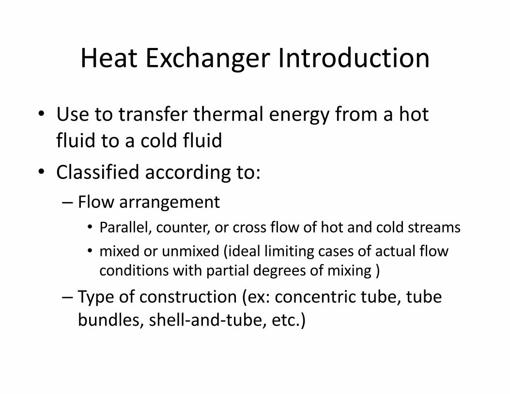
Heat Exchanger Introduction
• Use to transfer thermal energy from a hot fluid to a cold fluid
• Classified according to:– Flow arrangement• Parallel, counter, or cross flow of hot and cold streams• mixed or unmixed (ideal limiting cases of actual flow
conditions with partial degrees of mixing )
– Type of construction (ex: concentric tube, tube bundles, shell-and-tube, etc.)
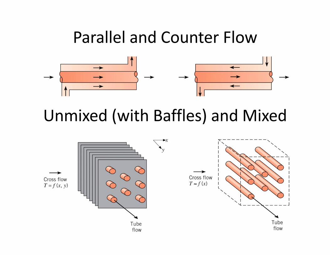
Parallel and Counter Flow
Unmixed (with Baffles) and Mixed
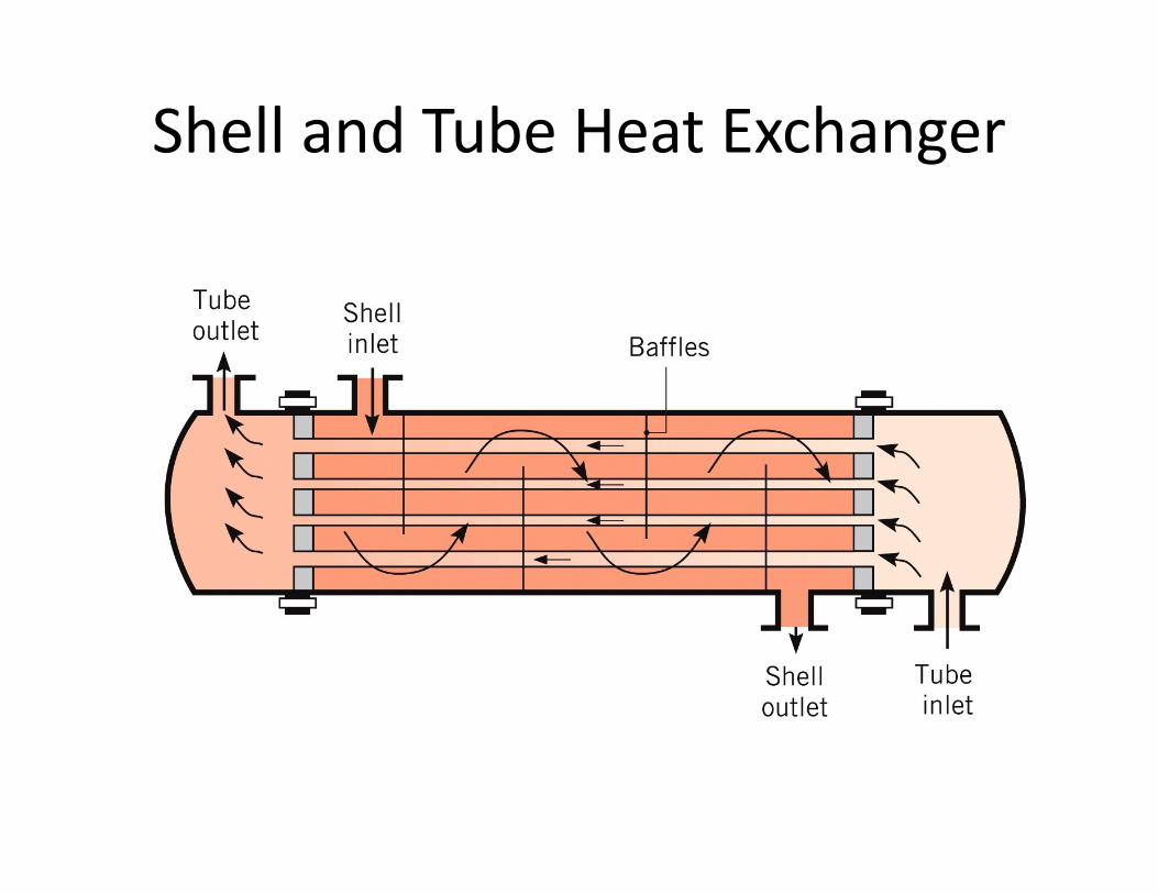
Shell and Tube Heat Exchanger
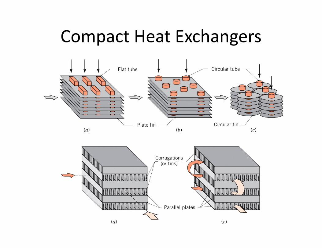
Compact Heat Exchangers
Special class of heat exchangers with:• Dense arrays of finned tubes or plates• Flow passages that are typically small (less than
about 5 mm)• For typical applications one fluid is a gas (with
low convection coefficient)• Very large heat transfer surface area per unit
volume, As/V:– Greater than 400 m2/m3 for liquids– Greater than 700 m2/m3 for gases
Compact Heat Exchangers
Heat Exchanger Analysis
Use to determine how overall heat transfer rate, q, depends on:
1. Inlet fluid temperatures, Th,i and Tc,i2. Outlet fluid temperatures, Th,o and Tc,o3. Mass flowrates, �̇�# and �̇�$
4. Overall heat transfer coefficient, U5. Surface area for heat transfer, A
where subscript h for hot fluid and c for cold fluid
Analysis Objectives
• Design: – Given 𝑇#,', 𝑇$,', �̇�#, �̇�$ and desired 𝑇#,( or 𝑇$,(– Specify heat exchanger type and 𝐴
• Performance: – Given a particular heat exchanger (with known 𝐴)
and operating conditions (𝑇#,', 𝑇$,', �̇�# and �̇�$)– Determine 𝑈, 𝑞, 𝑇#,(, and 𝑇$,(
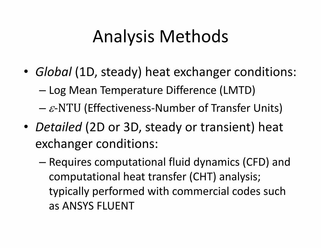
Analysis Methods
• Global (1D, steady) heat exchanger conditions:– Log Mean Temperature Difference (LMTD)– e-NTU (Effectiveness-Number of Transfer Units)
• Detailed (2D or 3D, steady or transient) heat exchanger conditions:– Requires computational fluid dynamics (CFD) and
computational heat transfer (CHT) analysis; typically performed with commercial codes such as ANSYS FLUENT
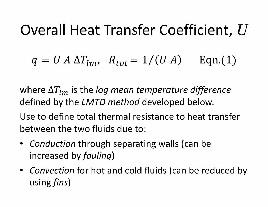
Overall Heat Transfer Coefficient, U
𝑞 = 𝑈 𝐴 Δ𝑇./, 𝑅1(1= ⁄1 𝑈 𝐴 Eqn.(1)
where Δ𝑇./ is the log mean temperature differencedefined by the LMTD method developed below.Use to define total thermal resistance to heat transfer between the two fluids due to:• Conduction through separating walls (can be
increased by fouling)• Convection for hot and cold fluids (can be reduced by
using fins)
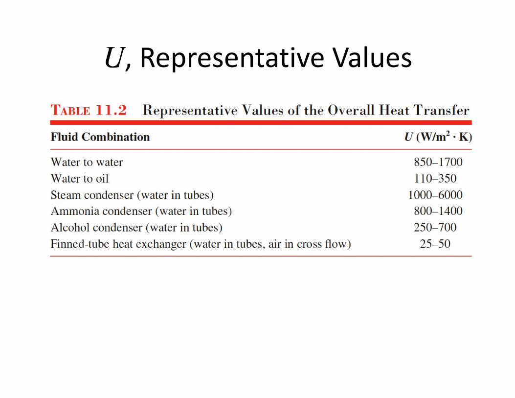
U, Representative Values
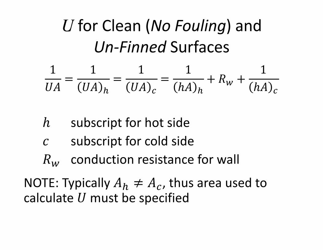
U for Clean (No Fouling) and Un-Finned Surfaces
1𝑈𝐴
=1𝑈𝐴 #
=1𝑈𝐴 $
=1ℎ𝐴 #
+ 𝑅< +1ℎ𝐴 $
ℎ subscript for hot side𝑐 subscript for cold side𝑅< conduction resistance for wall
NOTE: Typically 𝐴# ≠ 𝐴$, thus area used to calculate 𝑈 must be specified
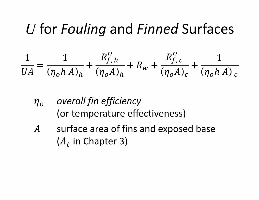
U for Fouling and Finned Surfaces
1𝑈𝐴
=1
𝜂(ℎ 𝐴 #+
𝑅@, #AA
𝜂(𝐴 #+ 𝑅< +
𝑅@, $AA
𝜂(𝐴 $+
1𝜂(ℎ 𝐴 $
𝜂( overall fin efficiency(or temperature effectiveness)
𝐴 surface area of fins and exposed base (𝐴1 in Chapter 3)
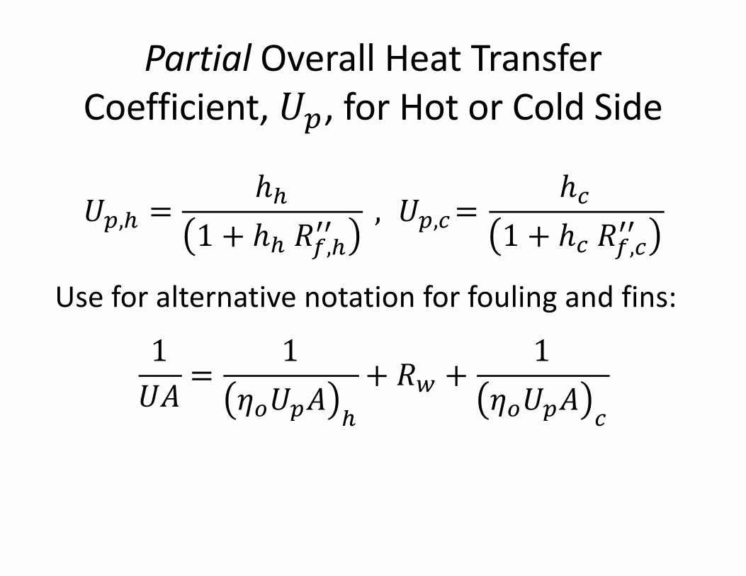
Partial Overall Heat Transfer Coefficient, 𝑈B, for Hot or Cold Side
𝑈B,# =ℎ#
1 + ℎ# 𝑅@,#AA, 𝑈B,$=
ℎ$1 + ℎ$ 𝑅@,$AA
Use for alternative notation for fouling and fins:
1𝑈𝐴
=1
𝜂(𝑈B𝐴 #
+ 𝑅< +1
𝜂(𝑈B𝐴 $
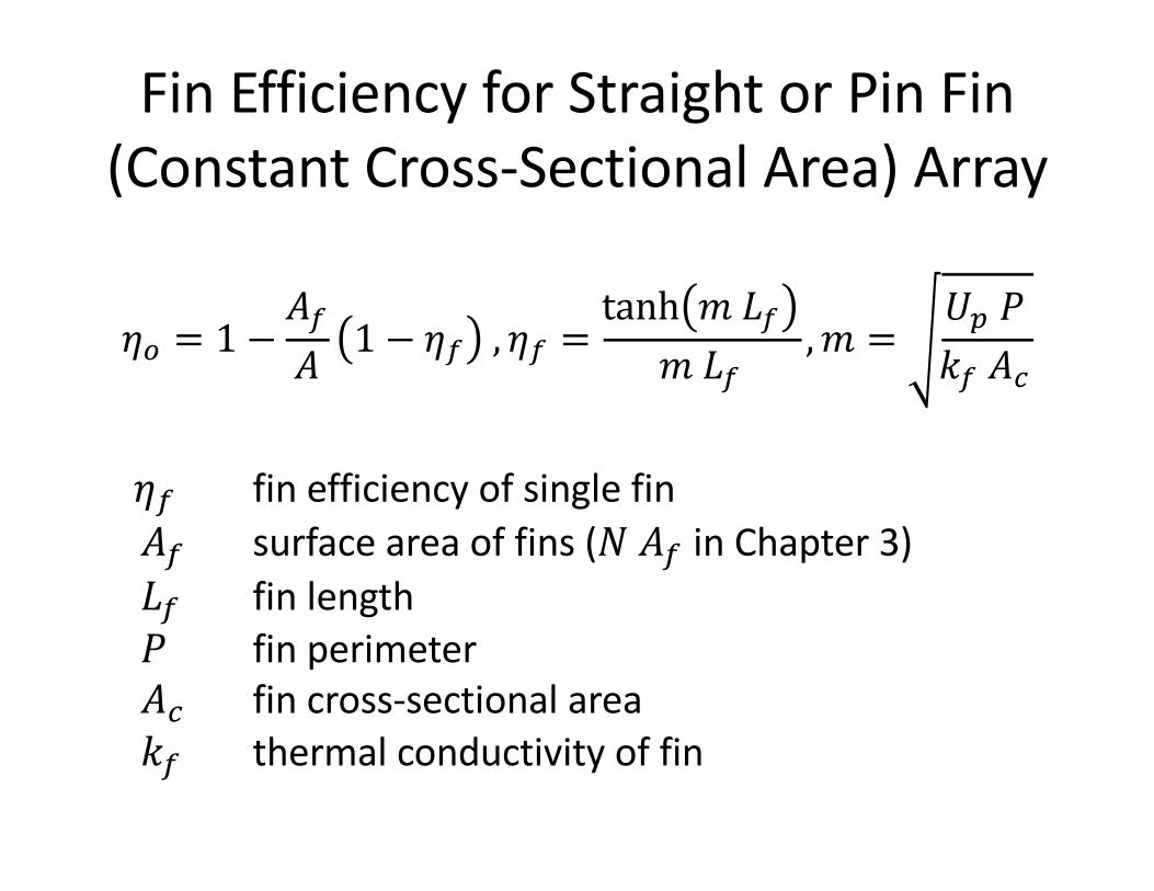
Fin Efficiency for Straight or Pin Fin (Constant Cross-Sectional Area) Array
𝜂( = 1 −𝐴@𝐴 1 − 𝜂@ , 𝜂@ =
tanh 𝑚 𝐿@𝑚 𝐿@
,𝑚 =𝑈B 𝑃𝑘@ 𝐴$
𝜂@ fin efficiency of single fin𝐴@ surface area of fins (𝑁 𝐴@ in Chapter 3)𝐿@ fin length𝑃 fin perimeter𝐴$ fin cross-sectional area𝑘@ thermal conductivity of fin
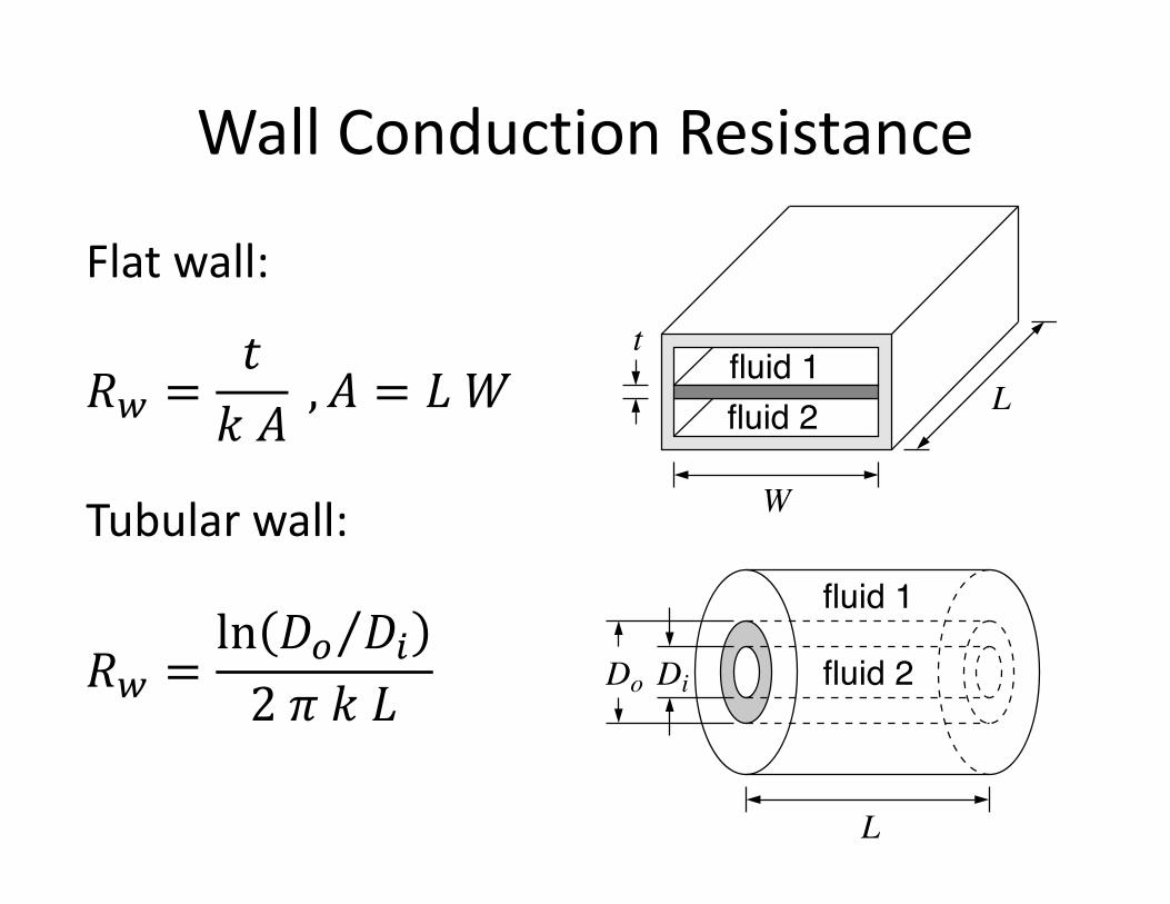
Wall Conduction Resistance
Flat wall:
𝑅< =𝑡𝑘 𝐴
, 𝐴 = 𝐿 𝑊
Tubular wall:
𝑅< =ln ⁄𝐷( 𝐷'2 𝜋 𝑘 𝐿
fluid 1fluid 2
t
W
L
fluid 1
fluid 2DiDo
L
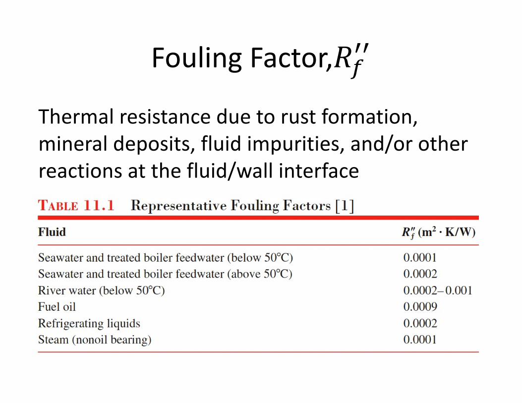
Fouling Factor,𝑅@AA
Thermal resistance due to rust formation, mineral deposits, fluid impurities, and/or other reactions at the fluid/wall interface
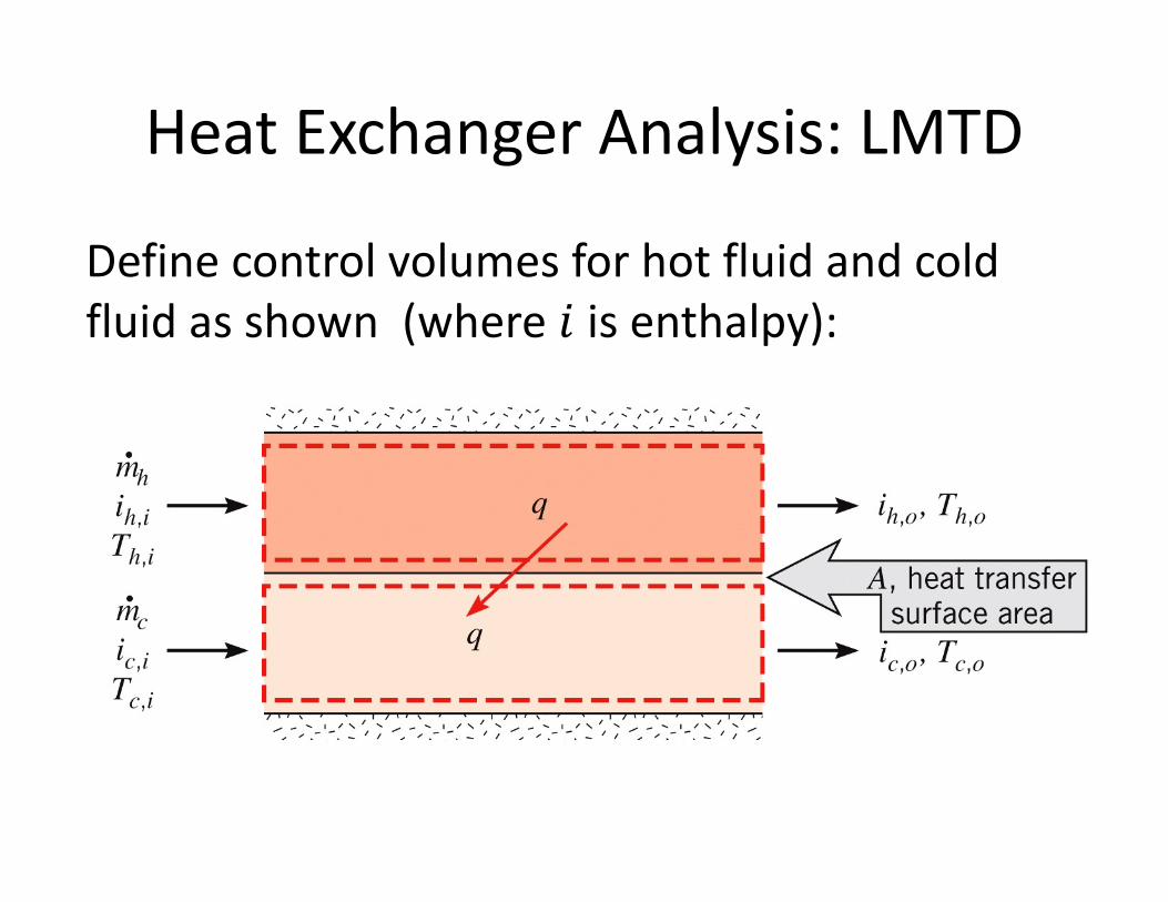
Heat Exchanger Analysis: LMTD
Define control volumes for hot fluid and cold fluid as shown (where 𝑖 is enthalpy):
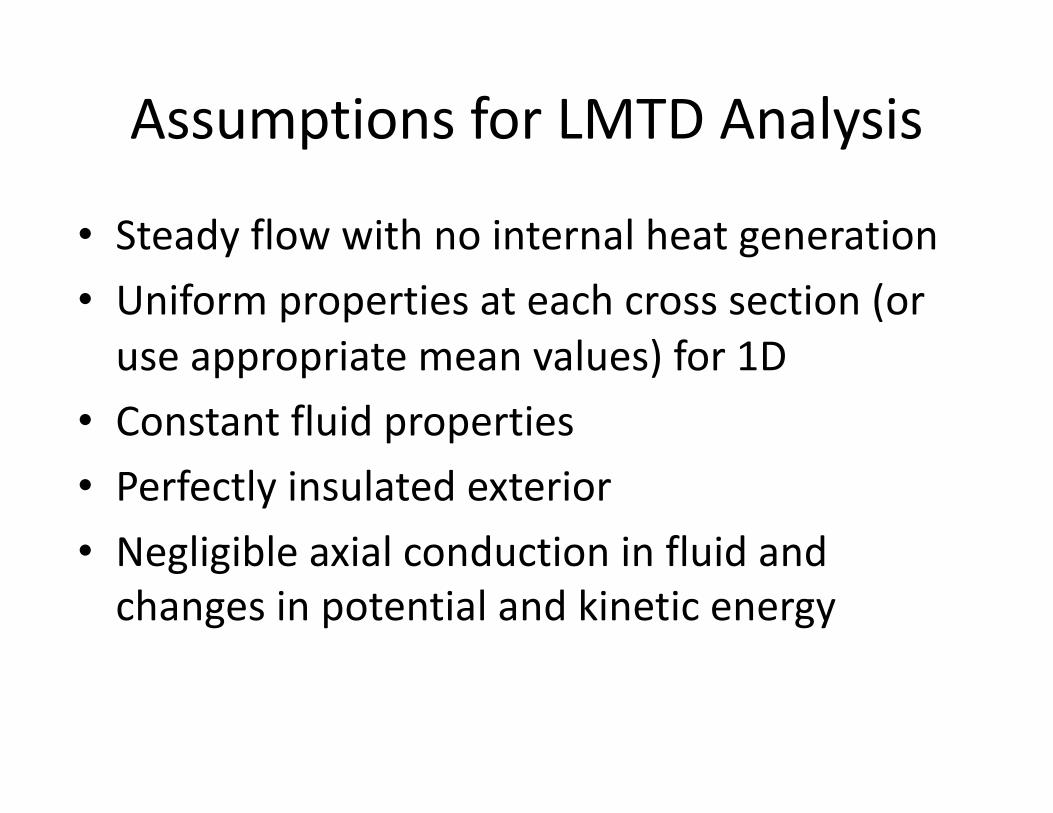
Assumptions for LMTD Analysis
• Steady flow with no internal heat generation• Uniform properties at each cross section (or
use appropriate mean values) for 1D• Constant fluid properties• Perfectly insulated exterior• Negligible axial conduction in fluid and
changes in potential and kinetic energy
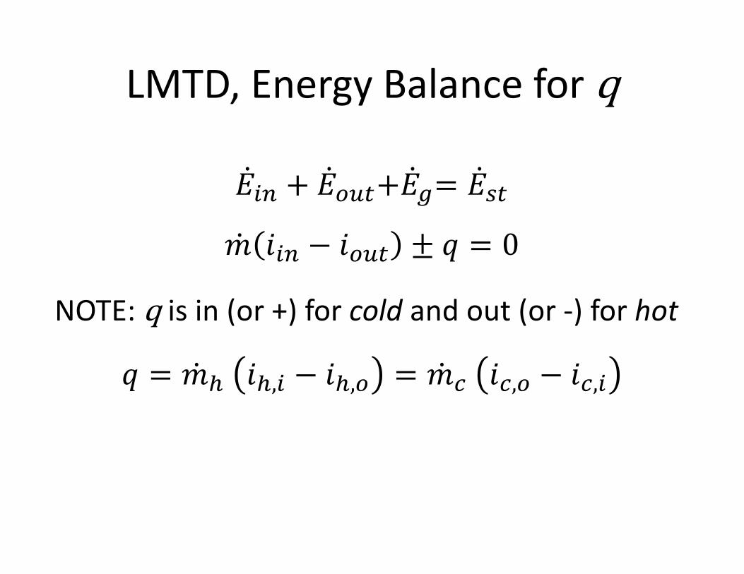
LMTD, Energy Balance for q
�̇�'S + �̇�(T1+�̇�U= �̇�V1
�̇� 𝑖'S − 𝑖(T1 ± 𝑞 = 0
NOTE: q is in (or +) for cold and out (or -) for hot
𝑞 = �̇�# 𝑖#,' − 𝑖#,( = �̇�$ 𝑖$,( − 𝑖$,'
Thermal Energy Transport
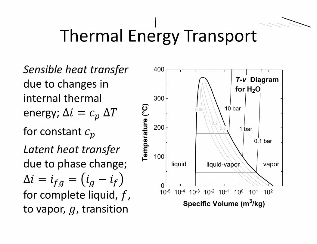
Sensible heat transfer due to changes in internal thermal energy; ∆𝑖 = 𝑐B ∆𝑇for constant 𝑐BLatent heat transferdue to phase change; ∆𝑖 = 𝑖@U = 𝑖U − 𝑖@for complete liquid, 𝑓, to vapor, 𝑔, transition
File:U:\EES_Files\ME_350\T_v_diagram_H2O.EES 6/3/2016 6:04:45 PM Page 1EES Ver. 9.902: #0552: for use only by students and faculty, Mechanical Engineering, Dept. Cal Poly State University
10-4 10-3 10-2 10-1 100 101 102 5x10²⁰
100
200
300
400
500
Specific Volume (m3/kg)
Tem
pera
ture
(°C
)
10 bar
5 bar
1 bar 0.5 bar
0.05 0.1
0.2 0.5
10-5 10-4 10-3 10-2 10-1 100 101 1020
100
200
300
400
Specific Volume (m3/kg)
Tem
pera
ture
(°C
)
10 bar
1 bar
0.1 bar
0.05
0.1 0.2
0.5
liquid liquid-vapor vapor
T-v Diagramfor H2O
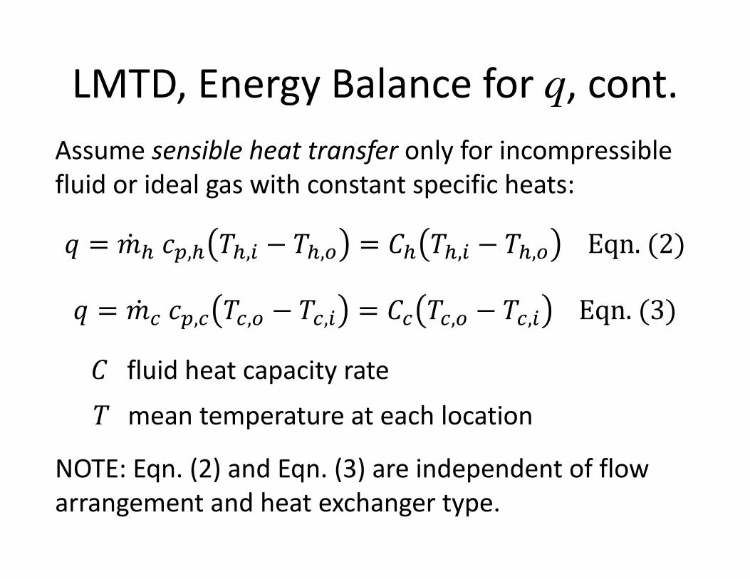
LMTD, Energy Balance for q, cont.Assume sensible heat transfer only for incompressible fluid or ideal gas with constant specific heats:
𝑞 = �̇�# 𝑐B,# 𝑇#,' − 𝑇#,( = 𝐶# 𝑇#,' − 𝑇#,( Eqn. (2)
𝑞 = �̇�$ 𝑐B,$ 𝑇$,( − 𝑇$,' = 𝐶$ 𝑇$,( − 𝑇$,' Eqn. (3)
C fluid heat capacity rate
T mean temperature at each location
NOTE: Eqn. (2) and Eqn. (3) are independent of flow arrangement and heat exchanger type.
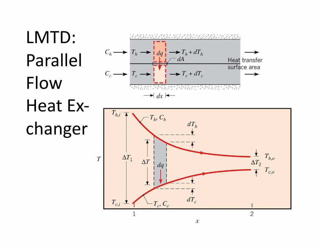
LMTD: Parallel FlowHeat Ex-changer
LMTD: Parallel Flow Heat Exchanger, cont.
• Section (1): both fluids at inlet; corresponds to maximum ∆𝑇: ∆𝑇 = 𝑇#,' − 𝑇$,'
• Section (2): both fluids at outlet; corresponds to minimum ∆𝑇: ∆𝑇_ = 𝑇#,( − 𝑇$,(
• ∆𝑇 between fluid streams approaches zero asymptotically with increasing length
• Must have 𝑇#,( > 𝑇$,(
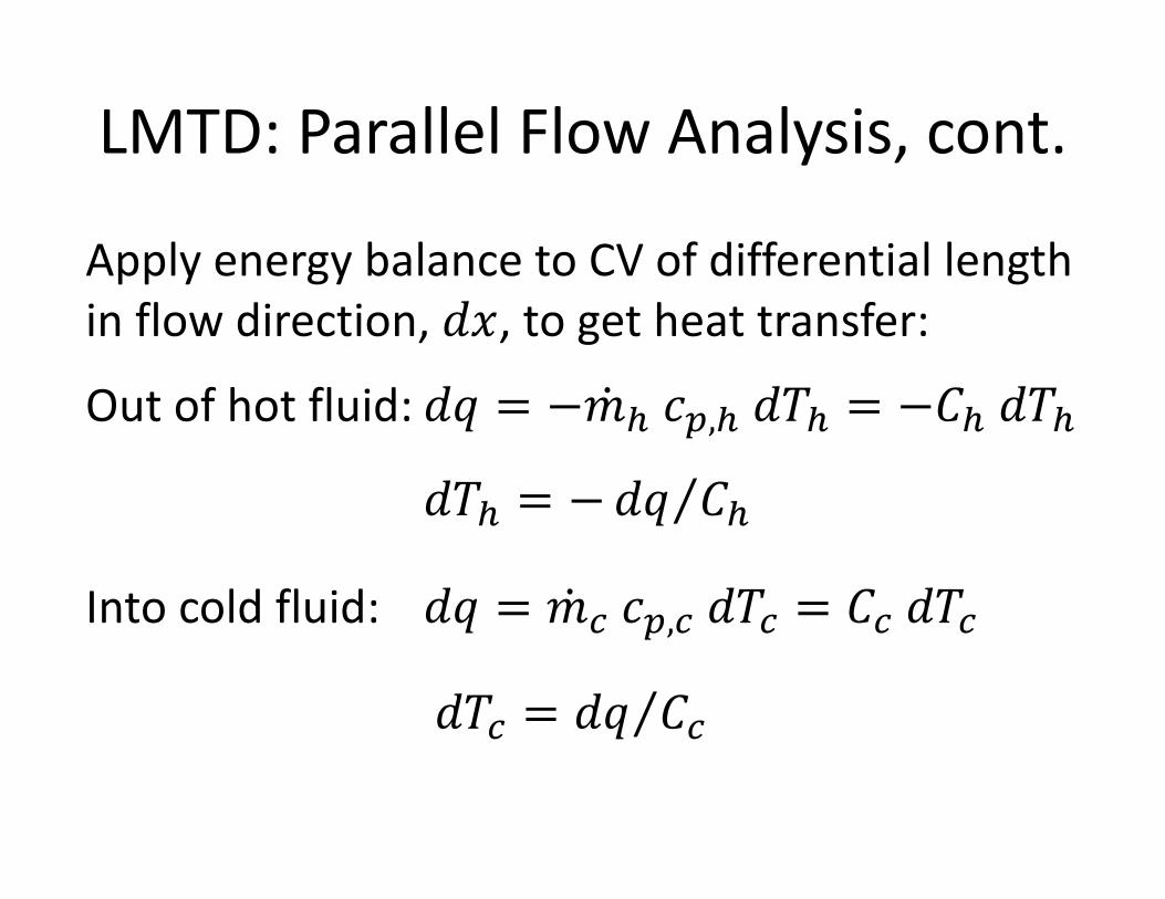
LMTD: Parallel Flow Analysis, cont.
Apply energy balance to CV of differential length in flow direction, 𝑑𝑥, to get heat transfer:
Out of hot fluid: 𝑑𝑞 = −�̇�# 𝑐B,# 𝑑𝑇# = −𝐶# 𝑑𝑇#
𝑑𝑇# = − ⁄𝑑𝑞 𝐶#
Into cold fluid: 𝑑𝑞 = �̇�$ 𝑐B,$ 𝑑𝑇$ = 𝐶$ 𝑑𝑇$
𝑑𝑇$ = ⁄𝑑𝑞 𝐶$
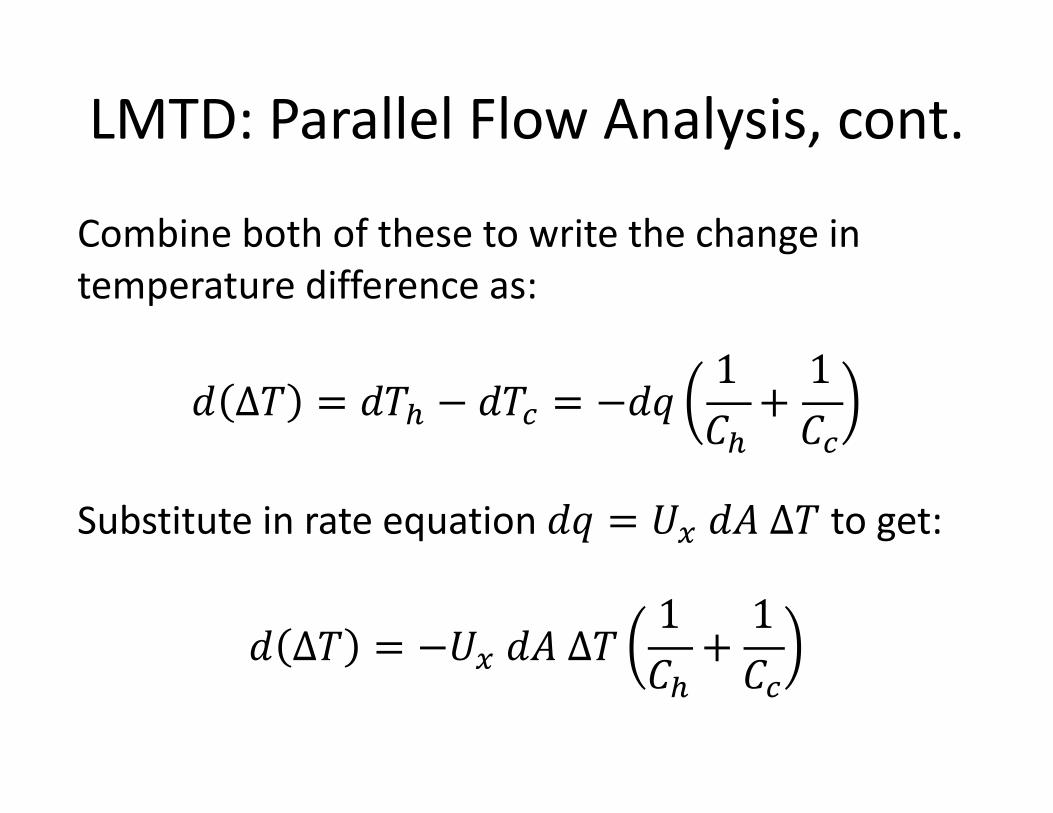
LMTD: Parallel Flow Analysis, cont.
Combine both of these to write the change in temperature difference as:
𝑑 ∆𝑇 = 𝑑𝑇# − 𝑑𝑇$ = −𝑑𝑞1𝐶#+1𝐶$
Substitute in rate equation 𝑑𝑞 = 𝑈c 𝑑𝐴 ∆𝑇 to get:
𝑑 ∆𝑇 = −𝑈c 𝑑𝐴 ∆𝑇1𝐶#+1𝐶$
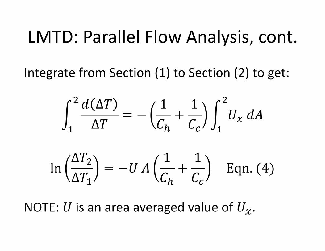
LMTD: Parallel Flow Analysis, cont.
Integrate from Section (1) to Section (2) to get:
d^
_ 𝑑 ∆𝑇∆𝑇
= −1𝐶#+1𝐶$
d^
_𝑈c 𝑑𝐴
ln∆𝑇_∆𝑇
= −𝑈 𝐴1𝐶#+1𝐶$
Eqn. (4)
NOTE: 𝑈 is an area averaged value of 𝑈c.
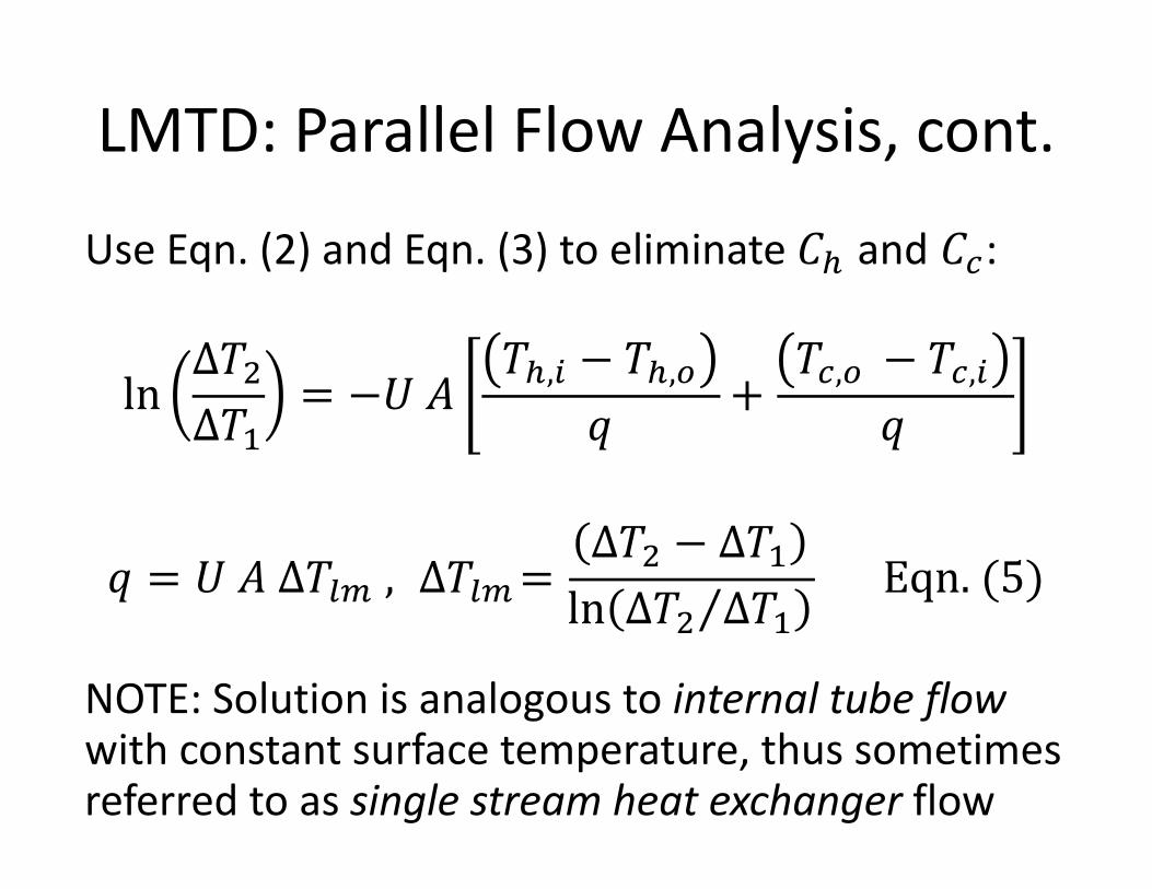
LMTD: Parallel Flow Analysis, cont.
Use Eqn. (2) and Eqn. (3) to eliminate 𝐶# and 𝐶$:
ln∆𝑇_∆𝑇
= −𝑈 𝐴𝑇#,' − 𝑇#,(
𝑞+
𝑇$,( − 𝑇$,'𝑞
𝑞 = 𝑈 𝐴 ∆𝑇./ , ∆𝑇./=∆𝑇_ − ∆𝑇ln ⁄∆𝑇_ ∆𝑇
Eqn. (5)
NOTE: Solution is analogous to internal tube flowwith constant surface temperature, thus sometimes referred to as single stream heat exchanger flow
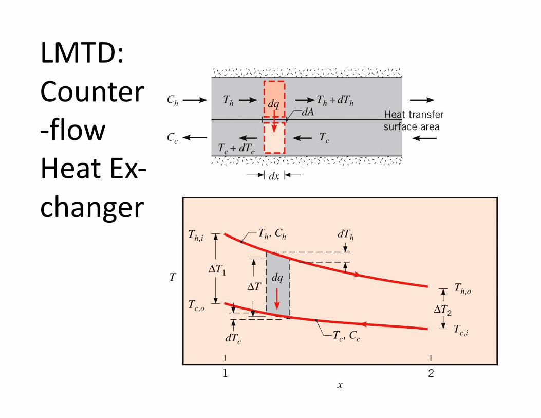
LMTD: Counter-flow Heat Ex-changer
LMTD: Counterflow Heat Exchanger, cont.
• Section (1): hottest portion of both fluid streams where ∆𝑇 = 𝑇#,' − 𝑇$,(
• Section (2): coldest portion of both fluid streams where ∆𝑇_= 𝑇#,( − 𝑇$,'
• Can now have 𝑇#,( > 𝑇$,(
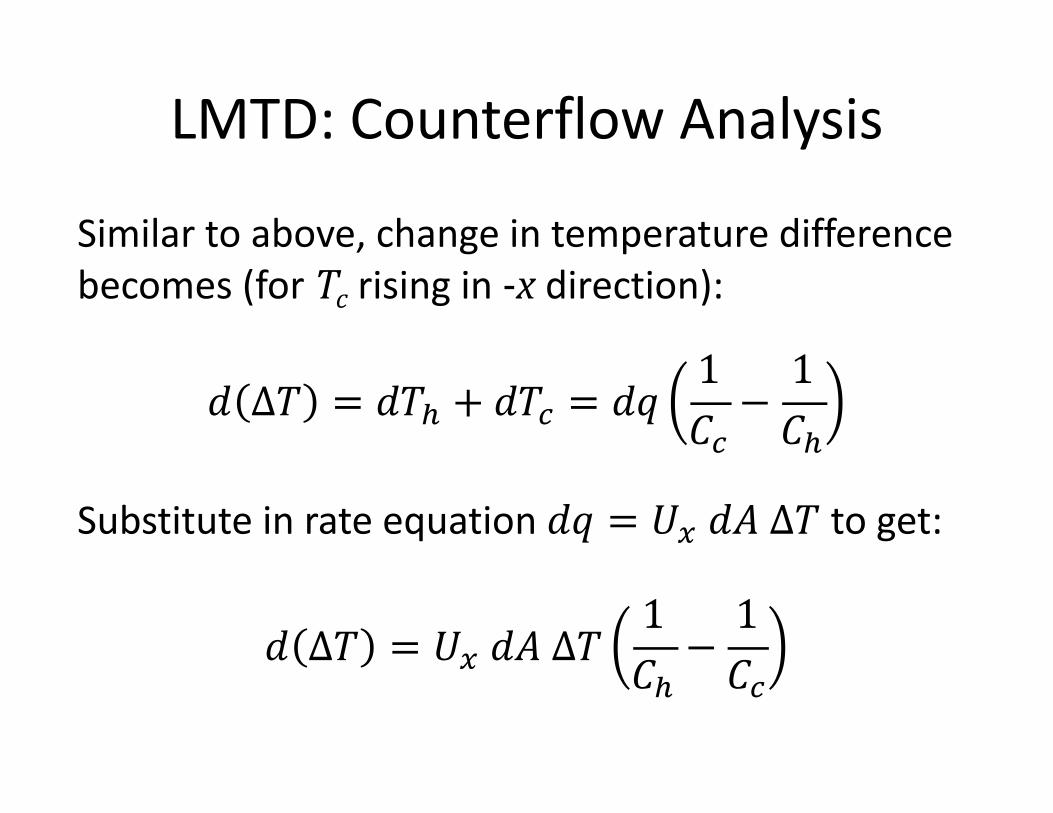
LMTD: Counterflow Analysis
Similar to above, change in temperature difference becomes (for Tc rising in -x direction):
𝑑 ∆𝑇 = 𝑑𝑇# + 𝑑𝑇$ = 𝑑𝑞1𝐶$−1𝐶#
Substitute in rate equation 𝑑𝑞 = 𝑈c 𝑑𝐴 ∆𝑇 to get:
𝑑 ∆𝑇 = 𝑈c 𝑑𝐴 ∆𝑇1𝐶#−1𝐶$
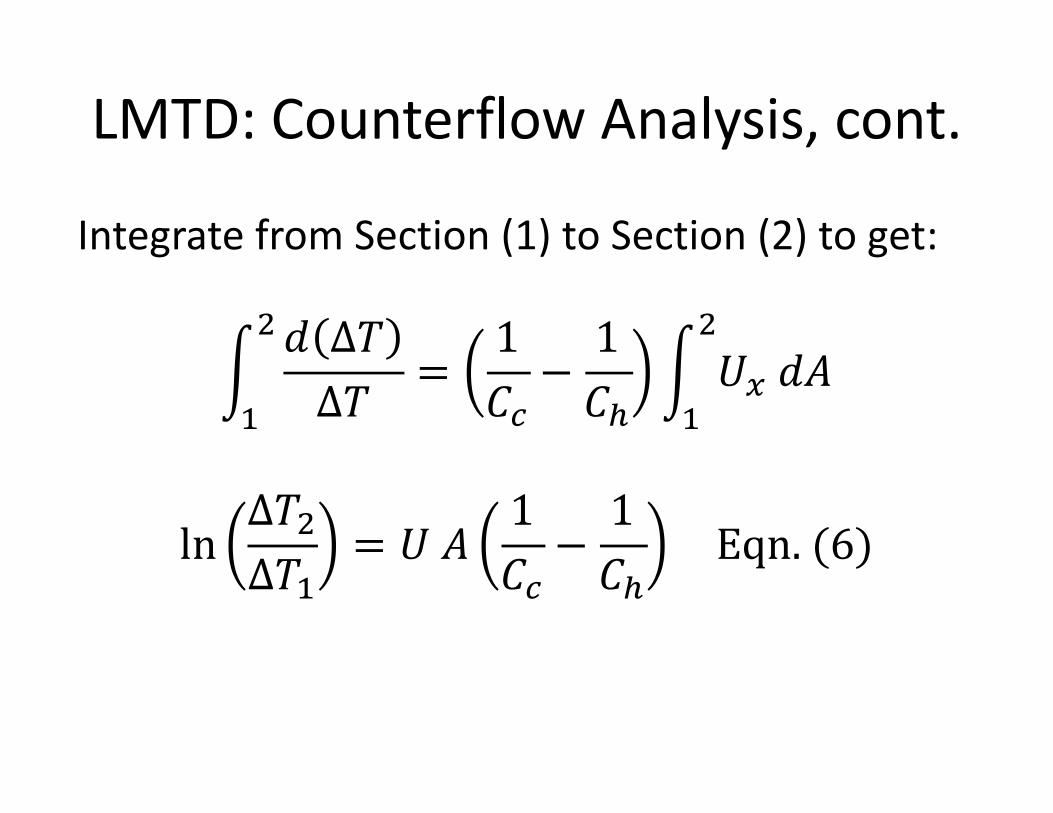
LMTD: Counterflow Analysis, cont.
Integrate from Section (1) to Section (2) to get:
d^
_ 𝑑 ∆𝑇∆𝑇
=1𝐶$−1𝐶#
d^
_𝑈c 𝑑𝐴
ln∆𝑇_∆𝑇
= 𝑈 𝐴1𝐶$−1𝐶#
Eqn. (6)
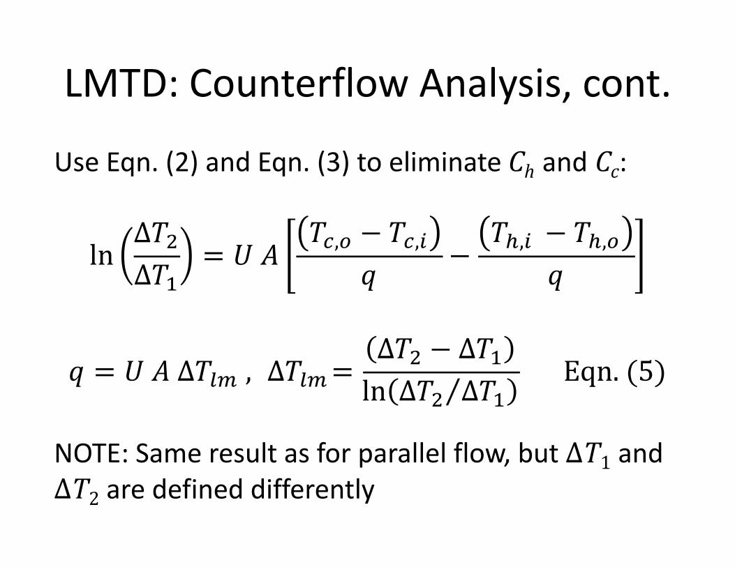
LMTD: Counterflow Analysis, cont.
Use Eqn. (2) and Eqn. (3) to eliminate Ch and Cc:
ln∆𝑇_∆𝑇
= 𝑈 𝐴𝑇$,( − 𝑇$,'
𝑞−
𝑇#,' − 𝑇#,(𝑞
𝑞 = 𝑈 𝐴 ∆𝑇./ , ∆𝑇./=∆𝑇_ − ∆𝑇ln ⁄∆𝑇_ ∆𝑇
Eqn. (5)
NOTE: Same result as for parallel flow, but ∆T1 and ∆T2 are defined differently
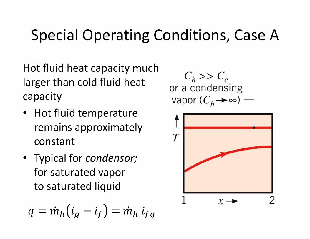
Special Operating Conditions, Case A
Hot fluid heat capacity much larger than cold fluid heat capacity• Hot fluid temperature
remains approximately constant
• Typical for condensor; for saturated vapor to saturated liquid
𝑞 = �̇�# 𝑖U − 𝑖@ = �̇�# 𝑖@U
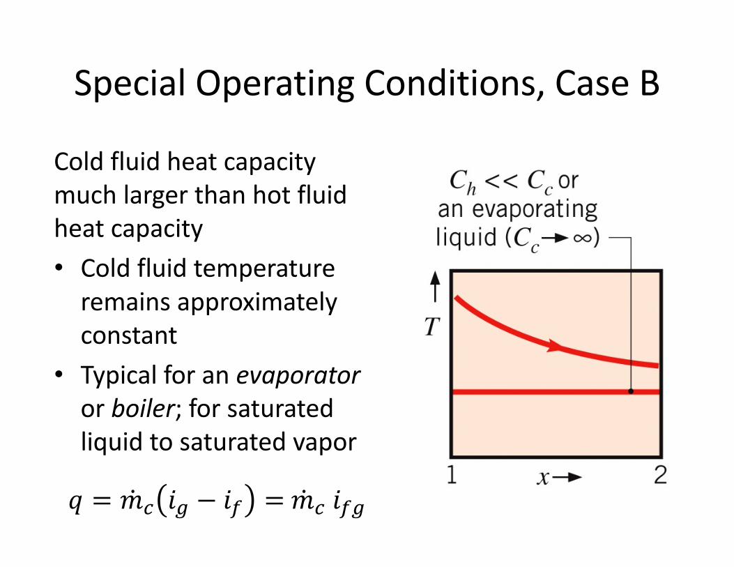
Special Operating Conditions, Case B
Cold fluid heat capacity much larger than hot fluid heat capacity• Cold fluid temperature
remains approximately constant
• Typical for an evaporator or boiler; for saturated liquid to saturated vapor
𝑞 = �̇�$ 𝑖U − 𝑖@ = �̇�$ 𝑖@U
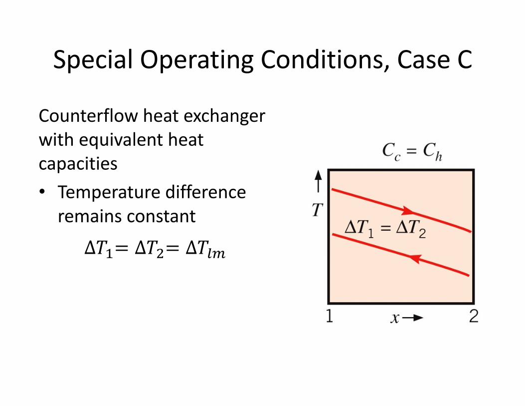
Special Operating Conditions, Case C
Counterflow heat exchanger with equivalent heat capacities• Temperature difference
remains constant
∆𝑇 = ∆𝑇_= ∆𝑇./
Heat Exchanger Analysis: 𝜀 − NTU
• Alternative approach that does not require iteration for problems with unknown fluid outlet temperatures
• Use technique to solve for 𝑈𝐴 product directly, but would still need to solve for 𝑈separately to determine 𝐴
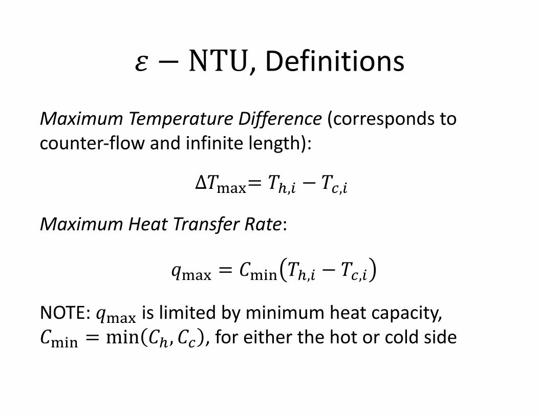
𝜀 − NTU, Definitions
Maximum Temperature Difference (corresponds to counter-flow and infinite length):
∆𝑇lmn= 𝑇#,' − 𝑇$,'
Maximum Heat Transfer Rate:
𝑞lmn = 𝐶lop 𝑇#,' − 𝑇$,'
NOTE: 𝑞lmn is limited by minimum heat capacity, 𝐶lop = min 𝐶#, 𝐶$ , for either the hot or cold side
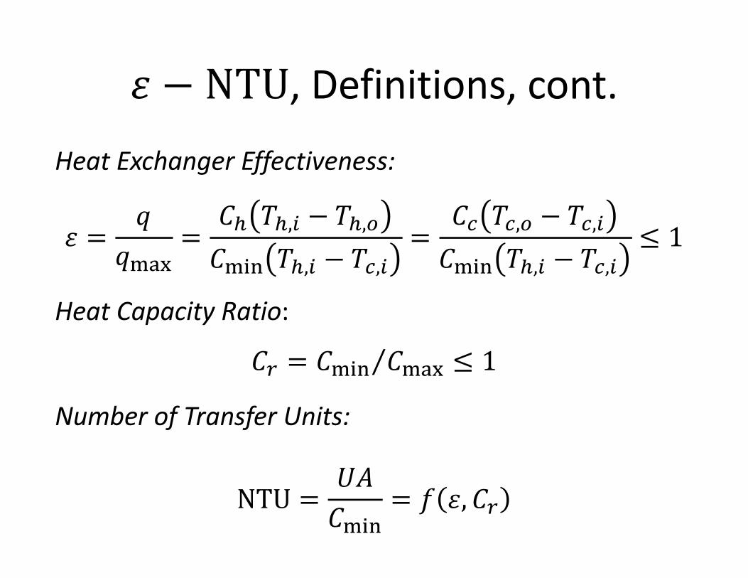
𝜀 − NTU, Definitions, cont.
Heat Exchanger Effectiveness:
𝜀 =𝑞
𝑞lmn=
𝐶# 𝑇#,' − 𝑇#,(𝐶lop 𝑇#,' − 𝑇$,'
=𝐶$ 𝑇$,( − 𝑇$,'𝐶lop 𝑇#,' − 𝑇$,'
≤ 1
Heat Capacity Ratio:
𝐶t = ⁄𝐶lop 𝐶lmn ≤ 1
Number of Transfer Units:
NTU =𝑈𝐴𝐶lop
= 𝑓 𝜀, 𝐶t
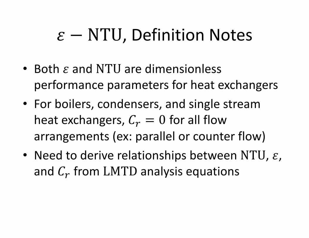
𝜀 − NTU, Definition Notes
• Both 𝜀 and NTU are dimensionless performance parameters for heat exchangers
• For boilers, condensers, and single stream heat exchangers, 𝐶t = 0 for all flow arrangements (ex: parallel or counter flow)
• Need to derive relationships between NTU, 𝜀, and 𝐶t from LMTD analysis equations
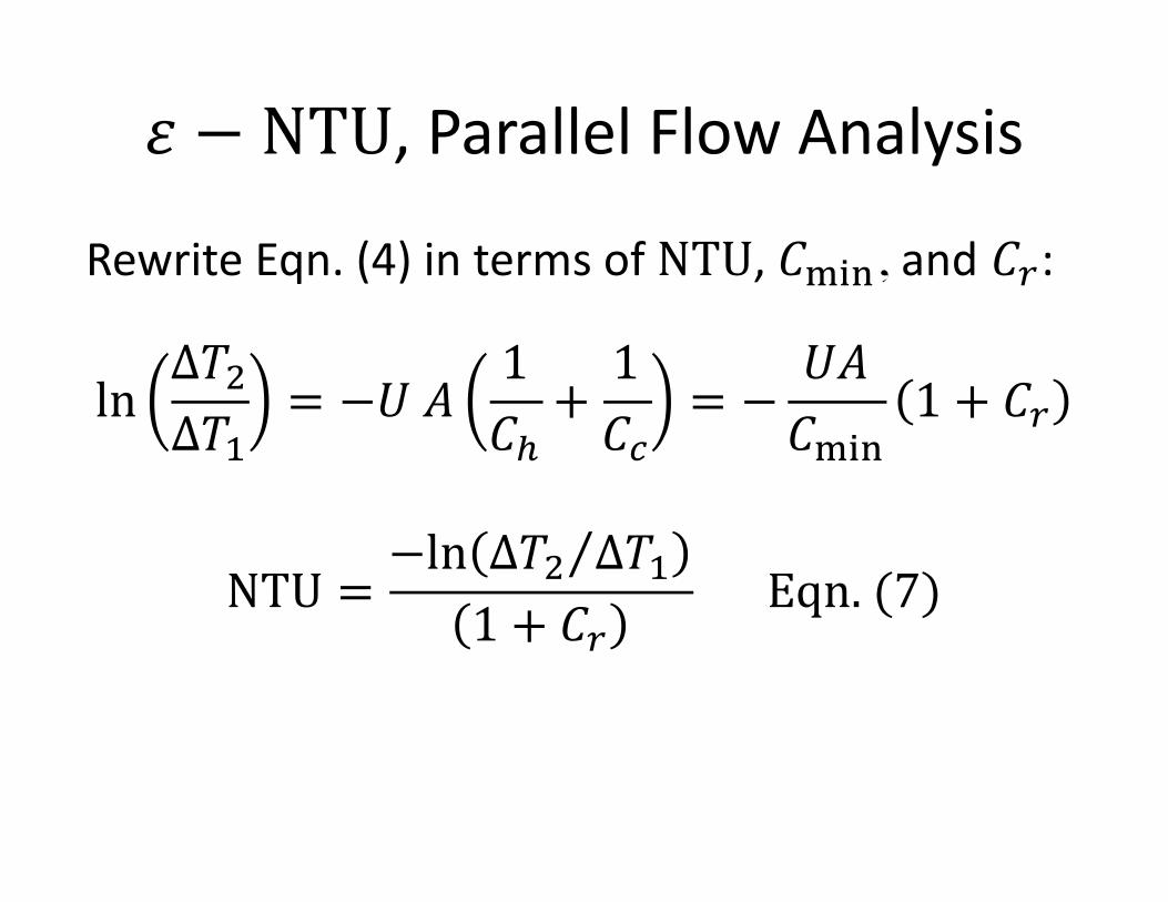
𝜀 − NTU, Parallel Flow Analysis
Rewrite Eqn. (4) in terms of NTU, 𝐶lop, and 𝐶t:
ln∆𝑇_∆𝑇
= −𝑈 𝐴1𝐶#+1𝐶$
= −𝑈𝐴𝐶lop
1 + 𝐶t
NTU =−ln ⁄∆𝑇_ ∆𝑇
1 + 𝐶tEqn. (7)
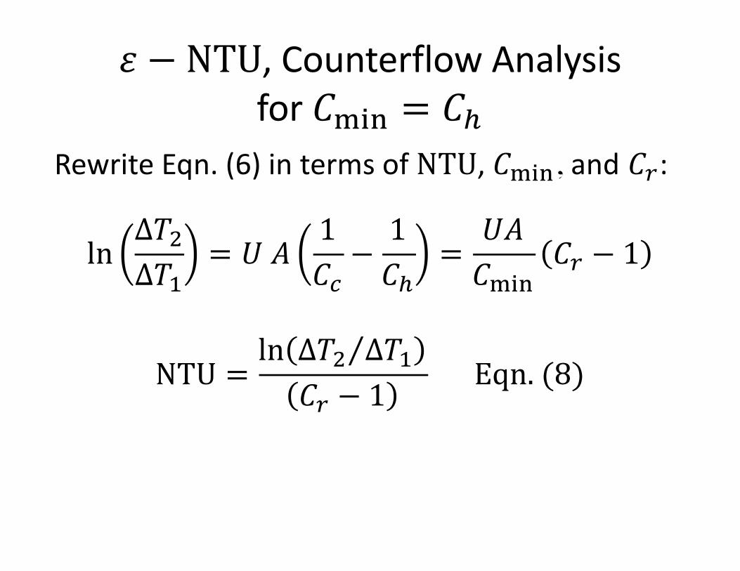
𝜀 − NTU, Counterflow Analysis for 𝐶lop = 𝐶#
Rewrite Eqn. (6) in terms of NTU, 𝐶lop, and 𝐶t:
ln∆𝑇_∆𝑇
= 𝑈 𝐴1𝐶$−1𝐶#
=𝑈𝐴𝐶lop
𝐶t − 1
NTU =ln ⁄∆𝑇_ ∆𝑇𝐶t − 1
Eqn. (8)
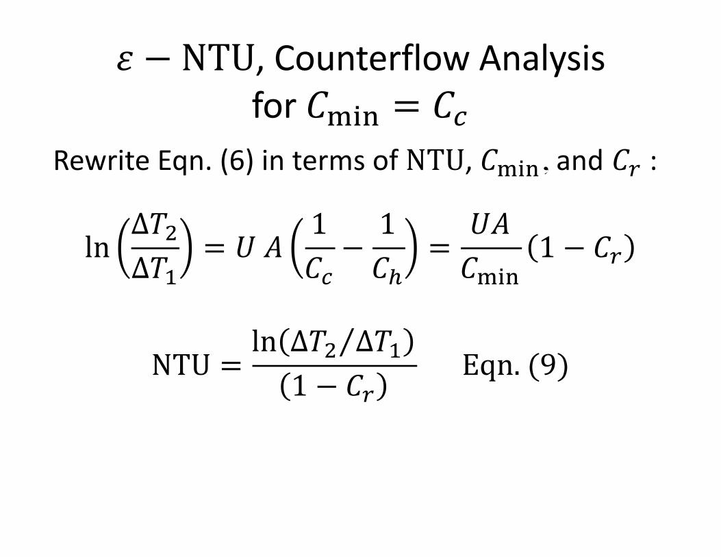
𝜀 − NTU, Counterflow Analysisfor 𝐶lop = 𝐶$
Rewrite Eqn. (6) in terms of NTU, 𝐶lop, and 𝐶t :
ln∆𝑇_∆𝑇
= 𝑈 𝐴1𝐶$−1𝐶#
=𝑈𝐴𝐶lop
1 − 𝐶t
NTU =ln ⁄∆𝑇_ ∆𝑇1 − 𝐶t
Eqn. (9)
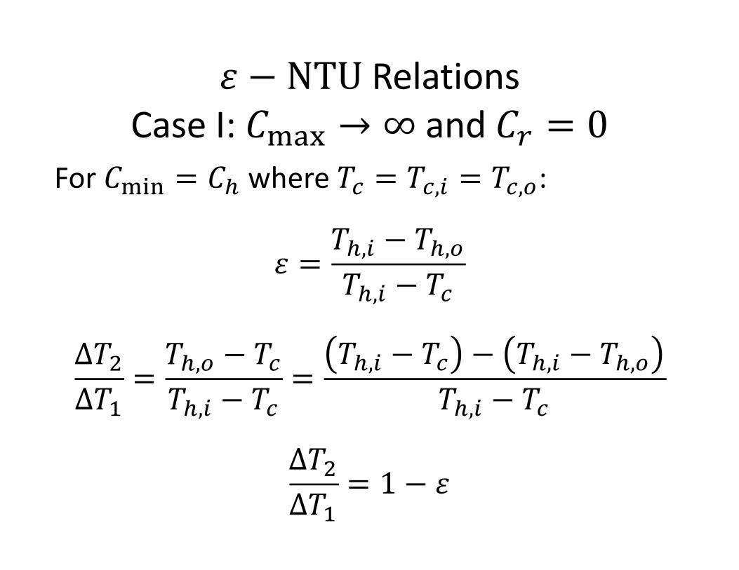
𝜀 − NTU Relations Case I: 𝐶lmn → ∞ and 𝐶t = 0
For 𝐶lop = 𝐶# where 𝑇$ = 𝑇$,' = 𝑇$,(:
𝜀 =𝑇#,' − 𝑇#,(𝑇#,' − 𝑇$
∆𝑇_∆𝑇
=𝑇#,( − 𝑇$𝑇#,' − 𝑇$
=𝑇#,' − 𝑇$ − 𝑇#,' − 𝑇#,(
𝑇#,' − 𝑇$
∆𝑇_∆𝑇
= 1 − 𝜀
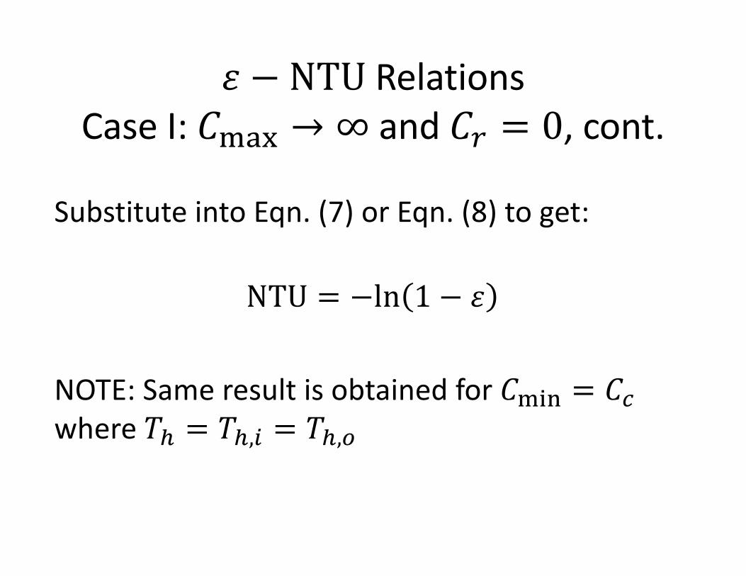
𝜀 − NTU Relations Case I: 𝐶lmn → ∞ and 𝐶t = 0, cont.
Substitute into Eqn. (7) or Eqn. (8) to get:
NTU = −ln 1 − 𝜀
NOTE: Same result is obtained for 𝐶lop = 𝐶$where 𝑇# = 𝑇#,' = 𝑇#,(
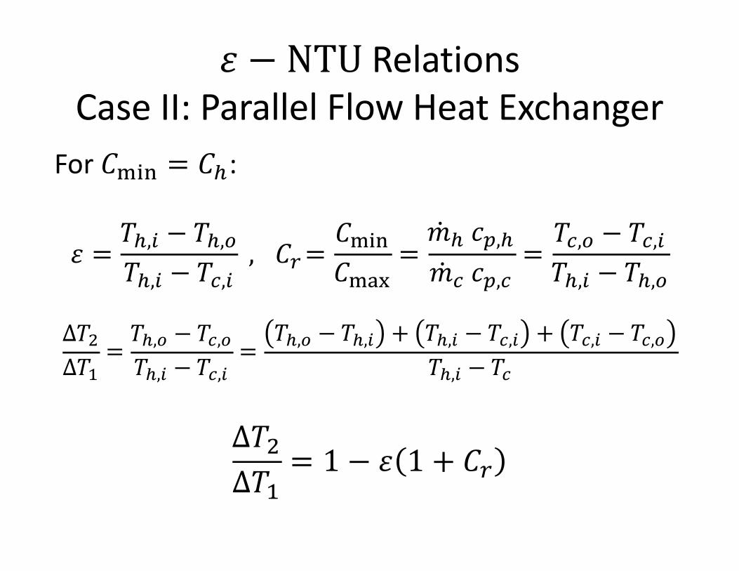
𝜀 − NTU Relations Case II: Parallel Flow Heat Exchanger
For 𝐶lop = 𝐶#:
𝜀 =𝑇#,' − 𝑇#,(𝑇#,' − 𝑇$,'
, 𝐶t=𝐶lop𝐶lmn
=�̇�# 𝑐B,#�̇�$ 𝑐B,$
=𝑇$,( − 𝑇$,'𝑇#,' − 𝑇#,(
∆𝑇_∆𝑇 =
𝑇#,( − 𝑇$,(𝑇#,' − 𝑇$,'
=𝑇#,( − 𝑇#,' + 𝑇#,' − 𝑇$,' + 𝑇$,' − 𝑇$,(
𝑇#,' − 𝑇$
∆𝑇_∆𝑇
= 1 − 𝜀 1 + 𝐶t
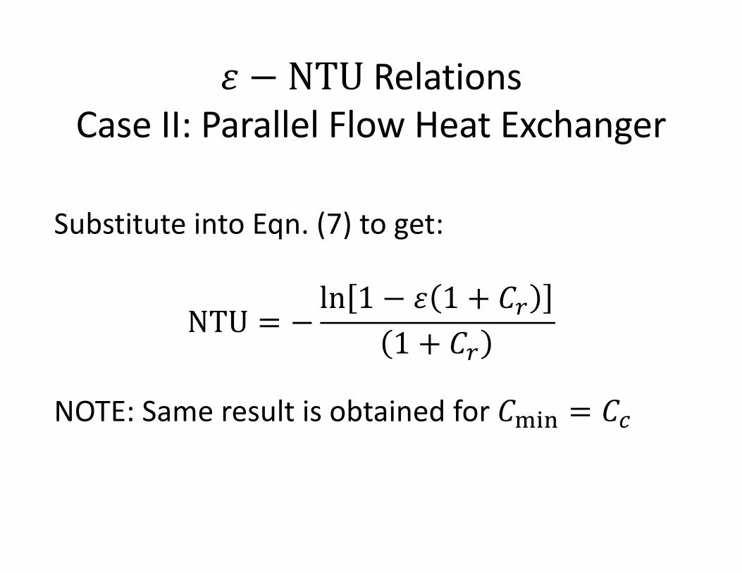
𝜀 − NTU Relations Case II: Parallel Flow Heat Exchanger
Substitute into Eqn. (7) to get:
NTU = −ln 1 − 𝜀 1 + 𝐶t
1 + 𝐶t
NOTE: Same result is obtained for 𝐶lop = 𝐶$
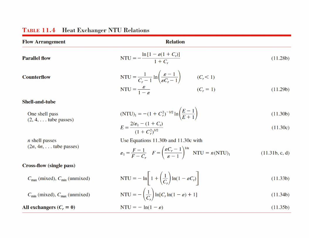
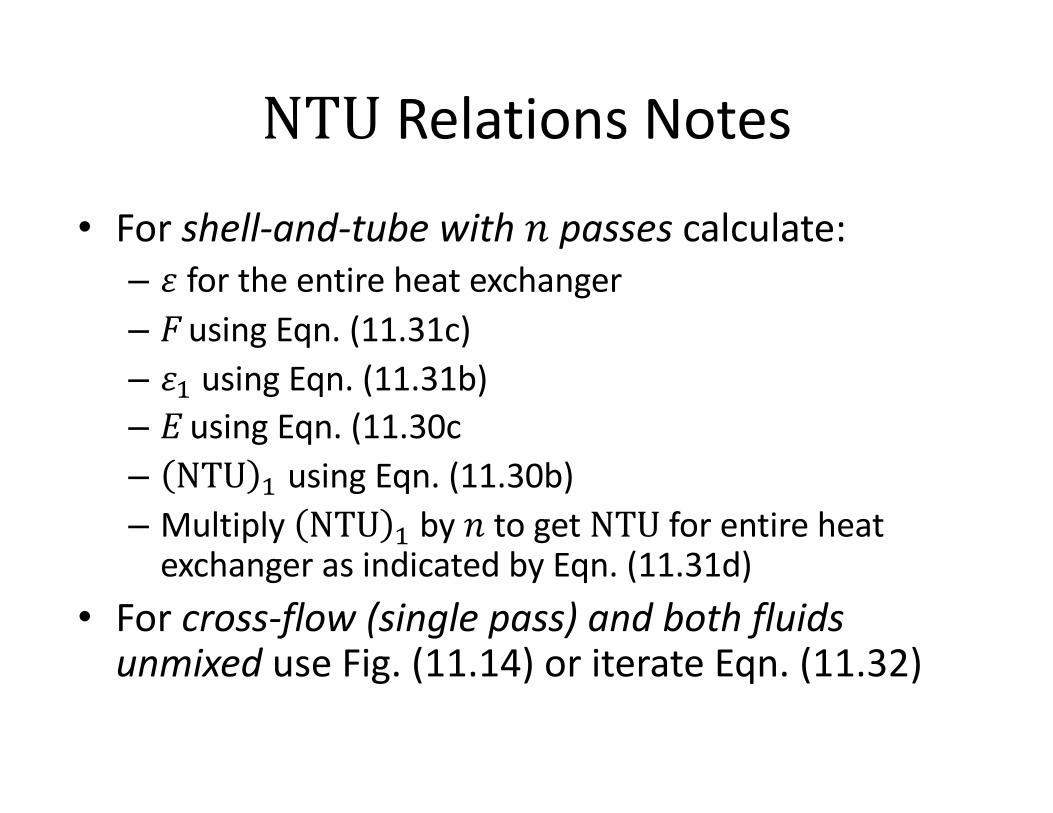
NTU Relations Notes
• For shell-and-tube with 𝑛 passes calculate:– 𝜀 for the entire heat exchanger– F using Eqn. (11.31c)– 𝜀^ using Eqn. (11.31b)– E using Eqn. (11.30c– NTU ^ using Eqn. (11.30b)– Multiply NTU ^ by 𝑛 to get NTU for entire heat
exchanger as indicated by Eqn. (11.31d)• For cross-flow (single pass) and both fluids
unmixed use Fig. (11.14) or iterate Eqn. (11.32)
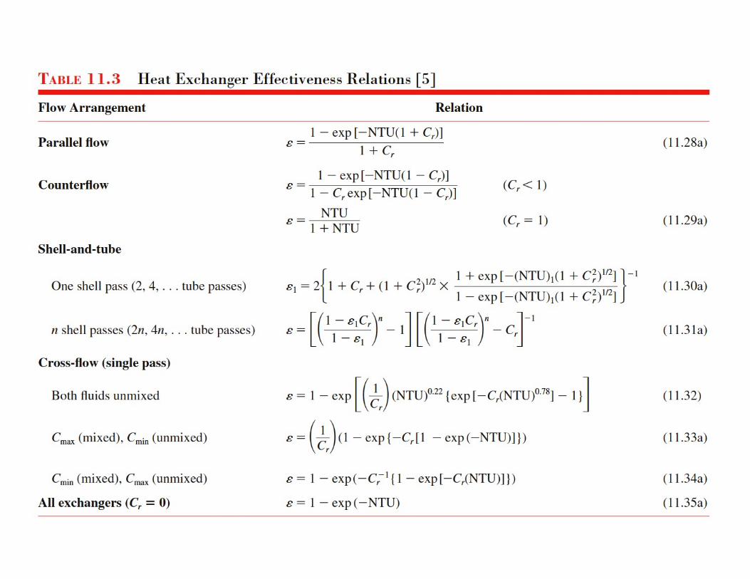
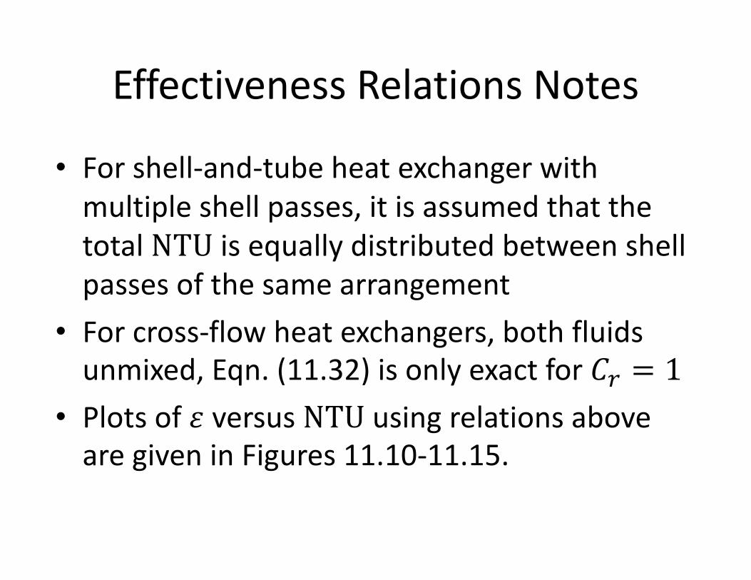
Effectiveness Relations Notes
• For shell-and-tube heat exchanger with multiple shell passes, it is assumed that the total NTU is equally distributed between shell passes of the same arrangement
• For cross-flow heat exchangers, both fluids unmixed, Eqn. (11.32) is only exact for 𝐶t = 1
• Plots of 𝜀 versus NTU using relations above are given in Figures 11.10-11.15.
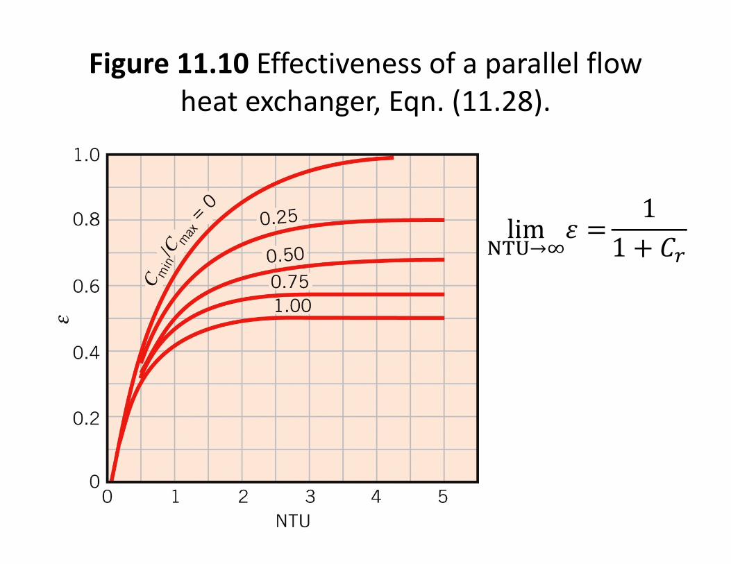
Figure 11.10 Effectiveness of a parallel flow heat exchanger, Eqn. (11.28).
lim{|}→~
𝜀 =1
1 + 𝐶t
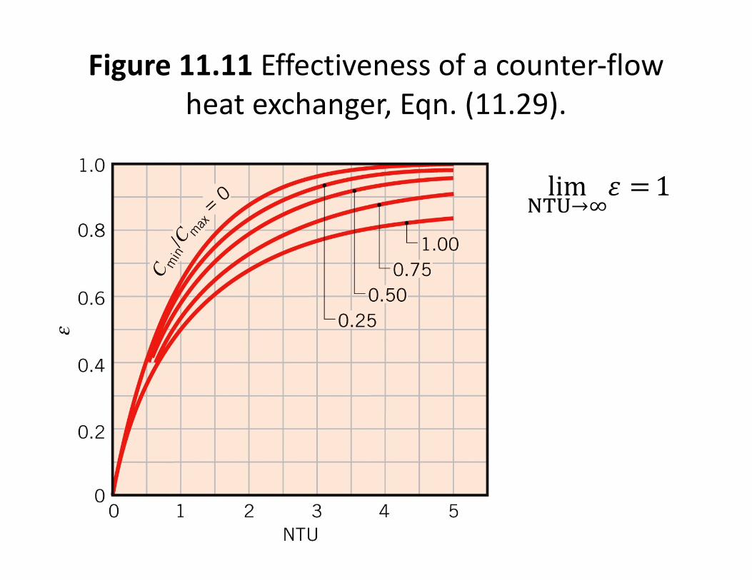
Figure 11.11 Effectiveness of a counter-flow heat exchanger, Eqn. (11.29).
lim{|}→~
𝜀 =1
Notes on Figures
• For NTU < 0.25 all heat exchangers have approximately the same 𝜀; can use Eqn. (11.35a)
• For NTU > 0.25, in general counter-flow heat exchanger is the most effective
• For any heat exchanger, maximum e when 𝐶t = 0 (typically for one side with phase change) and minimum 𝜀 when 𝐶t = 1(Example: same fluids and mass flowrates)