mcs - laboratorium apparatuur onderhoud mcs-ii english.pdf · 2 2.1. 2.1.1 installation / start-up...
TRANSCRIPT
MCS
Instruction Manual IMPORTANT: Read this manual before starting the instrument
Rev. 03 (05/2007)
© Copyright: Duplication of this manual by any means for any purpose without written consent of SLEE Medical GmbH is prohibited.
SLEE Medical GmbH - Lise-Meitner-Str.1 - D-55129 Mainz Tel. +49 6131 95871-0 - Fax +49 6131 95871-22 - [email protected]

Table of contents 1 GENERAL INFORMATION
Page
1.1 1.2 1.3
Introduction Functional elements Functions
1 2 3
1.3.1 Mechanical components 1.3.2 Operating surface
3 3 / 4
1.4 2 2.1
Technical data INSTALLATION / START UP Installation
5
6 2.1.1 Reference 2.1.2 Set up, Place, fan installation
6 6
2.2 Start up 8 2.2.1 Switching on 2.2.2 Filling up the system with xylene or mounting media 2.2.3 Filling up the reservoir of xylene
8 9
11 2.3 Program setup 13 2.3.1 Cycle time 2.3.2 Cover glass size 2.3.3 Selection line and/or point mode and media quantity 2.3.4 Setup pressure 2.3.5 Memory of the setup data 3 Operation
13 14 15 15 16
3.1 3.2 3.3
Normal operation Program selection Starting the coverslipping procedure
18 21 22
3.3.1 Coverslipping with given parameters 3.3.2 Changing parameters during operation
22 23
3.4. 3.5 3.6 4
Modifying stored data Interrupting the coverslipping process Switching the instrument off Error messages
24 24 24 25
4.1 Coverglass 25 4.1.1 ADD COVERGLASS 4.1.2 COVERGLASS BROKEN 4.1.3 CG VACUUM ERROR
25 26 27
4.2 Slides 28 4.2.1 SG PICK UP ERROR 4.2.2 SG STORAGE ERROR
28 29
4.3 Battery 30 4.3.1 BATTERY POWER LOW 30 4.4 ERROR CODE messages 31 4.5 5 5.1 5.2 5.3 5.4
ERRORCODE LIST Maintenance and care General Care Regular maintenance Disposal
32
33 33 34 34

GENERAL INFORMATION
Thank you for purchasing the MCS slide coverslipping machine from SLEE Medical GmbH Germany. The following instructions shall help you to use the instrument. Please read them thoroughly and follow the advices.
1.1 INTRODUCTION
The robot coverslipping machine MCS brings up covering media and cover glasses on slides with pathological tissue samples or cytological specimens to save working time of laboratory personal and also have less fatiguing work and impairment of the health by harmful solvent steams.
The slide baskets can be taken directly from staining automats into the MCS. With various adapters for all commercial staining automats, resorting is not necessary.
Operation errors are indicated to users in the LCD which is integrated in the operating surface. The messages are specified in an error code list, that informs the user in which phase the error appeared (explanations s. Page 32).
The equipment is only to be used for its targeted application, in order to not endanger the safety of humans and the preservation of fortune. The exclusive application of the MCS is coverslipping tissue slides.
1


1.3 Functions
1.3.1. Mechanical components
(1) Basket-xylene container for slide baskets with colored preparations (2) Conveyor rail is the surface for the basket-xylene container (3) Mounting media container containes the mountant media (4) Dispenser stand is the working position for the dispenser (5) Storage rack takes up the finished covered slides (6) Hood prevents the withdrawal of xylene steam and protects the tissues against dust
during coverslipping. (7) Elevator moves the storage racks up and down, in order to place the covered slides (8) Dispenser puts the adjusted quantity of mounting media on the slides (9) Cover glass case container for cover glasses (10) Exhaust port to connect an exhaust air mechanism (11) Cover glass stand to adjust the cover glass case in the correct position (12) CG Head patented system to take up, hold and put a cover glass on the slide (13) Main switch at the connection box at the rear of the instrument. Normally switched
on and only to be switched off if the instrument is not used for a longer period. (14) Fuses: in the connection box are 2 fuses of 3,15 A each. In case of an error in the
electric connection the fuses interrupt the current supply. (15) Xylene reservoir, for needle of dispenser (16) Xylene container, for the mounting media pump (17) Purge cap, used for catching up dripping mounting media, to be cleaned regularly !
1.3.2 Operating surface LCD
CURSOR ENTER
CLEAR
A (EMERGENCY)
FINGER STOP
RESTART
START
POWER
3
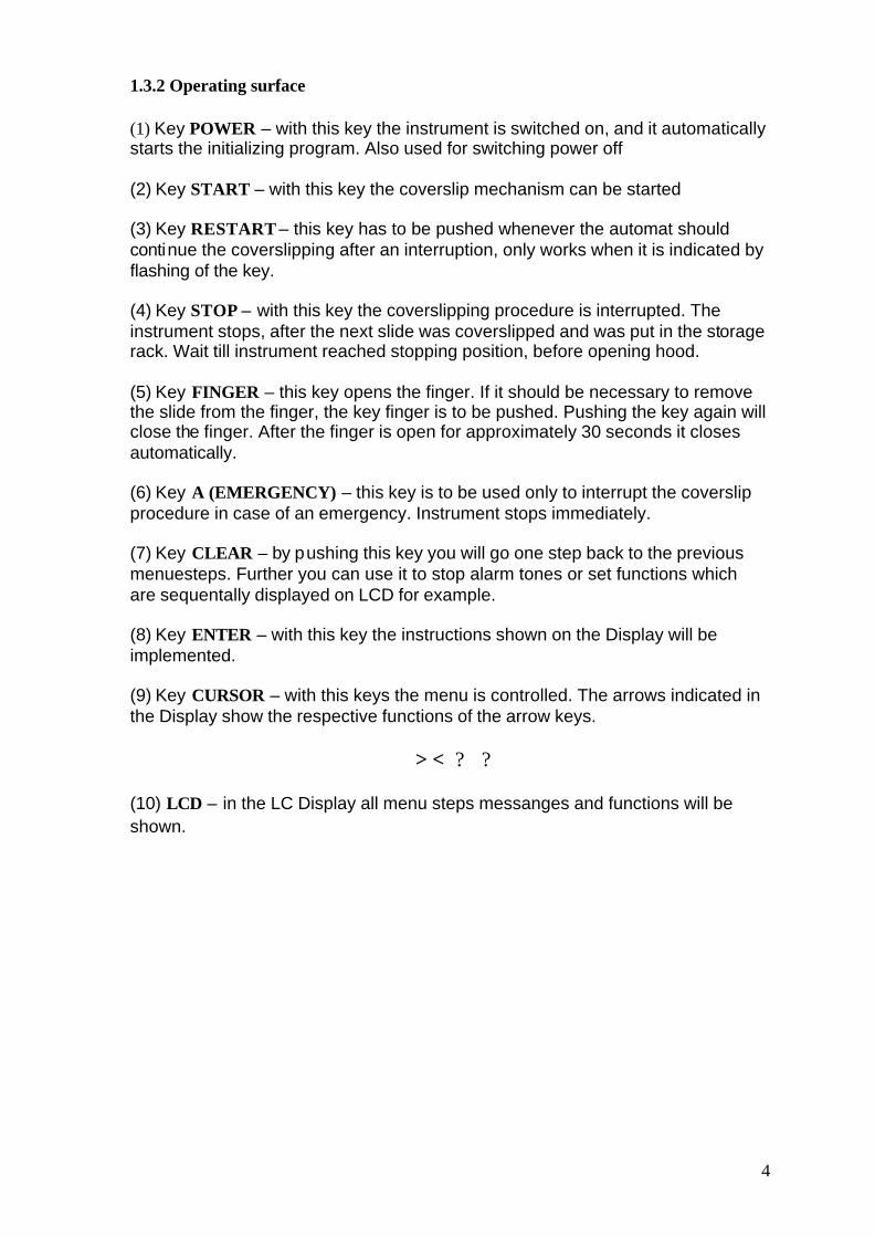
1.3.2 Operating surface
(1) Key POWER – with this key the instrument is switched on, and it automatically starts the initializing program. Also used for switching power off
(2) Key START – with this key the coverslip mechanism can be started
(3) Key RESTART – this key has to be pushed whenever the automat should continue the coverslipping after an interruption, only works when it is indicated by flashing of the key.
(4) Key STOP – with this key the coverslipping procedure is interrupted. The instrument stops, after the next slide was coverslipped and was put in the storage rack. Wait till instrument reached stopping position, before opening hood.
(5) Key FINGER – this key opens the finger. If it should be necessary to remove the slide from the finger, the key finger is to be pushed. Pushing the key again will close the finger. After the finger is open for approximately 30 seconds it closes automatically.
(6) Key A (EMERGENCY) – this key is to be used only to interrupt the coverslip procedure in case of an emergency. Instrument stops immediately.
(7) Key CLEAR – by pushing this key you will go one step back to the previous menuesteps. Further you can use it to stop alarm tones or set functions which are sequentally displayed on LCD for example.
(8) Key ENTER – with this key the instructions shown on the Display will be implemented.
(9) Key CURSOR – with this keys the menu is controlled. The arrows indicated in the Display show the respective functions of the arrow keys.
> < ? ?
(10) LCD – in the LC Display all menu steps messanges and functions will be shown.
4
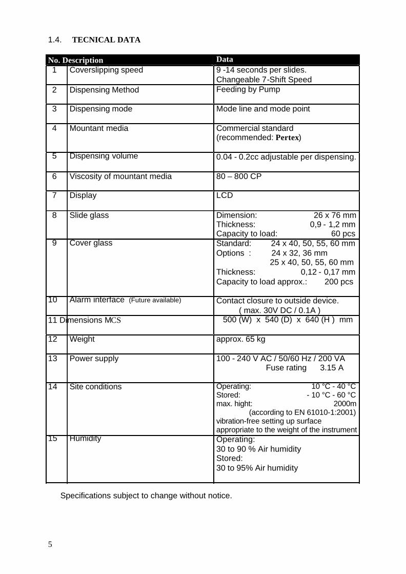
1.4. TECNICAL DATA
No. Description 1 Coverslipping speed
2 Dispensing Method
3 Dispensing mode
4 Mountant media
5 Dispensing volume
6 Viscosity of mountant media
7 Display
8 Slide glass
9 Cover glass
10 Alarm interface (Future available)
11 Dimensions MCS
12 Weight
13 Power supply
14 Site conditions
15 Humidity
Data 9 -14 seconds per slides. Changeable 7-Shift Speed Feeding by Pump
Mode line and mode point
Commercial standard (recommended: Pertex)
0.04 - 0.2cc adjustable per dispensing.
80 – 800 CP
LCD
Dimension: 26 x 76 mm Thickness: 0,9 - 1,2 mm Capacity to load: 60 pcs Standard: 24 x 40, 50, 55, 60 mm Options : 24 x 32, 36 mm 25 x 40, 50, 55, 60 mm Thickness: 0,12 - 0,17 mm Capacity to load approx.: 200 pcs
Contact closure to outside device. ( max. 30V DC / 0.1A )
500 (W) x 540 (D) x 640 (H ) mm
approx. 65 kg
100 - 240 V AC / 50/60 Hz / 200 VA Fuse rating 3.15 A
Operating: 10 °C - 40 °C Stored: - 10 °C - 60 °C max. hight: 2000m (according to EN 61010-1:2001) vibration-free setting up surface appropriate to the weight of the instrument Operating: 30 to 90 % Air humidity Stored: 30 to 95% Air humidity
5
Specifications subject to change without notice.

2
2.1.
2.1.1
INSTALLATION / START-UP
INSTALLATION
REFERENCE
The MCS is a sensitive, electromechanical equipment. In order to avoid defects in the electronic circuit, the following references are to be absolutely considered. The equipment should only operate, if it is connected to a central exhaust air system or equipped with an activated charcoal filter. (option)
2.1.2
(1) Place
SET UP
The equipment should be set up in a way which ensures that the user can serve the instrument well and the exhaust air hose is attached. The place should be selected in that way, that the legally given maximum concentrations of solvent steams are not exceeded ( Please consider the safety data sheet of the mounting media manufacturer ). It should not be set up at places, at which it is exposed to the following:
o A Vibrations o B Direct sunlight, or art light o C Variations in temperature, e.g. beside air conditioning systems o D Splash-water,humidity, oil, dust o E Devices, which run with high voltage
Before switching on the instrument check the compatibility of voltage and frequency with the indications on the instrument label on the back of the unit. The Unit should have a distance of at least 10cm to neighbouring walls or other instruments to ensure sufficiently air interchange.
2) Remove the adhesive strip
Remove the adhesive strips at the hood and at the front flap.
(3) Connection of the fan
These works have to be accomplished only by an authorized service technician. Attach the fan to the black-brown cable of the equipment (See fig. Page 7 above, patch cords at the fan). Fasten the fan to the equipment with the existing 4 screws (See fig. Page 7 down). Now an exhaust air hose with 60 mm size (See fig. down) can be attached. The exhaust air hose has to be resistent to the used mountant media and solvents.
6

1.)
After installation of the fan it has to be activated in the service menu.
With the following instruction you will get to the FAN SETUP MENUE:
OPERATOR-MENUE? SERVICE? SUB MENUE? FAN-SETUP
By pressing the key ? in the Sub-Menue, on the LCD display the fan-set-up appears. Please press the key ? (ON), if you would like to use an exhaust. To deactivate the exhaust please press the key ? (OFF). With the key < (ON) you are able to dry the coverlipped slides with the small blower. To deactivate the blower just press the key > (OFF).
2.)
<SUB-MENU> ? : 1CYCLE OPERATION
> : LAMP, BUZZER TEST ? : FAN-SETUP CLR: RTN
FAN: DRY (#) EXHAUST (#) <: ON (1) ? : ON (1) >: OFF (0) ? : OFF (0)
CLR: RETURN
7
Press the key CLEAR to get back to go backt to the SERVICE menu

2.2
2.2.1
START UP
SWITCHING ON
Be sure to have the main switch at the rear of the instrument in position I. Then push the POWER key on the operating surface. On the LCD you will get the following announcement.
INITIALIZATION
OPEN DOOR/COVER AFTER MACHINE STOPS
Please pay attention to the front-door and the hood, they have to be closed.
As long as the display is lighted red, the instrument is initialising itself. If the initialization procedure is terminated the dispay with announcement of the following picture becomes green.
OPERATION MENU NO. # ? : PROG. <: SERVICE ? : SETUP >: FILL UP CLR: BACK TO HP ## sec
8

2.2.2 Filling up the system with xylene or mounting media
(1) Filling up the pump with mountant media
For a smooth operation of the instrument it is necessary to make sure that there is enough xylene available (for pump lubrication and sealing). In order to ensure this, the storage vessel attached at the front (right of the dispenser) must be constantly filled up with xylene (between "min." and "max."; see. fig. down).
(2) Filling and rinsing the system with xylene
9
1.
2.
3. 4.
5. 6.
Accomplish one flushing of the pump with xylene. (or with a solvent suitable to the mountant media you are using.) With the first installation it lasts due to air bubbles in the pump and hose approximately 2 – 3 fill up cycles, until the system is flushed completely (1cycle = approx. 5 min.) Use the fill up glass which is included to the accessory kit. Fill up the glass with xylene ( or with a solvent suitable to the mountant media you are using.) Insert the hose into the fill up glass. Prepare the provided jar for waste fluid for the running out xylene and place it on the conveyor rail right under the purge cap.

? Press the key > Filling up in the operating menue ? Next the announcement „Fill up with media“appears. ? Press the key < START. ? The announcement „IS JAR FOR WASTE FLUID READY?“ (Receptacle ready?) is shown. ? By pressing the key ENTER the instrument turn in position and begins to fill up the system with mountant media. Due to air bubbles in the pump and in the hose it lasts approx. 2 – 3 filling up cycles until the system flushes completely with mountant media ( 1 cycle = approx. 5 min.)
Finally you will reenter the operation menu by pressing the key CLEAR.
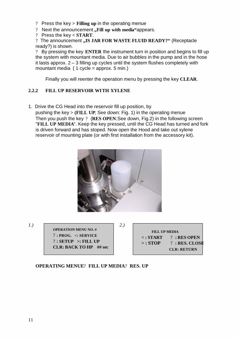
2.2.2 FILL UP RESERVOIR WITH XYLENE
1. Drive the CG Head into the reservoir fill up position, by pushing the key > (FILL UP; See down: Fig. 1) in the operating menue Then you push the key ? (RES OPEN;See down, Fig.2) in the following screen "FILL UP MEDIA". Keep the key pressed, until the CG Head has turned and fork is driven forward and has stoped. Now open the Hood and take out xylene reservoir of mounting plate (or with first installation from the accessory kit).
1.)
OPERATION MENU NO. #
? : PROG. <: SERVICE
? : SETUP >: FILL UP CLR: BACK TO HP ## sec
2.)
FILL UP MEDIA
< : START ? : RES OPEN > : STOP ? : RES. CLOSE
CLR: RETURN
11
OPERATING MENUE? FILL UP MEDIA? RES. UP

2. Fill up the provided washing bottle with xylene (or with a solvent suitable to the mountant media you are using.)
3. Fill up the reservoir xylene with the filled washing bottle, until it is filled to the half approx.. In addition to that turn the reservoir xylene to the right side. Then you fill the tank with the washing bottle carefully by the opening in the foot, until it is filled to the half approx.. Turn the reservoir of xylene carefully back again into the upright position.
4. Put the reservoir of xylene back into its mounting plate.
5. Drive the CG Head into the parking position, by pressing the key ? (RES. CLOSE; See down: Fig. 3) in the menu "MEDIUM FILLING UP".
3.)
FILL UP MEDIA
< : START ? : RES. OPEN > : STOP ? : RES. CLOSE
CLR: RETURN Be sure to keep the key pressed until the CG Head is driven back and down in its parking position and stoped motion.
Now push the key CLEAR, in order to reenter the operation menu.
12
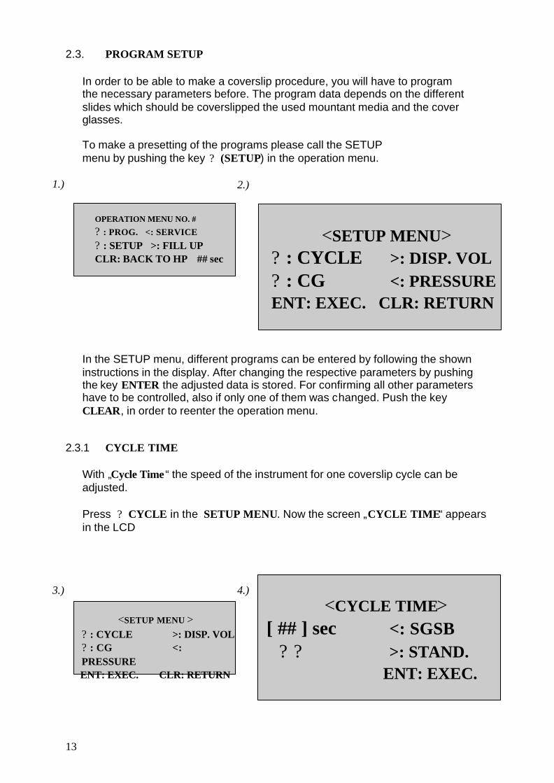
2.3.
PROGRAM SETUP
1.)
In order to be able to make a coverslip procedure, you will have to program the necessary parameters before. The program data depends on the different slides which should be coverslipped the used mountant media and the cover glasses.
To make a presetting of the programs please call the SETUP menu by pushing the key ? (SETUP) in the operation menu.
2.) OPERATION MENU NO. #
? : PROG. <: SERVICE
? : SETUP >: FILL UP CLR: BACK TO HP ## sec
<SETUP MENU> ? : CYCLE >: DISP. VOL ? : CG <: PRESSURE
ENT: EXEC. CLR: RETURN In the SETUP menu, different programs can be entered by following the shown instructions in the display. After changing the respective parameters by pushing the key ENTER the adjusted data is stored. For confirming all other parameters have to be controlled, also if only one of them was changed. Push the key CLEAR, in order to reenter the operation menu.
2.3.1 CYCLE TIME
With „Cycle Time “ the speed of the instrument for one coverslip cycle can be adjusted.
Press ? CYCLE in the SETUP MENU. Now the screen „CYCLE TIME“ appears in the LCD
3.)
13
<SETUP MENU >
? : CYCLE >: DISP. VOL ? : CG <: PRESSURE ENT: EXEC. CLR: RETURN
4.)
<CYCLE TIME> [ ## ] sec <: SGSB
? ? >: STAND. ENT: EXEC.

1. Press ? , to increase the duration of one Cycle for one second or more, and ? , to reduce it accordingly. The time can be entered from 9 to 14 seconds. (Displayed time refers to the STANDARD mode, SGSB will take a little more time)
2. The modes of cycle time as indicated in display (See, Fig. 4, page 15) :
SGSB (Slide Glass Standby): Before the MCS picks up a slide the sensors checks if the next cover glass is in good condition. According to standard the SLEE MCS is delivered in this mode. (program # 2). It can be changed alternatively by choosing it in this menue however.
STAND (standard): Coverglass and slides are taken up at the same time. A separate cover glass check is not used. This mode reaches a higher operating speed, but in case of arising interruptions it is necessary to restart the instrument completely.
Push the key ENTER to execute time changings and reenter the SETUP MENU.
2.3.2 COVERGLASS SIZE
Press ? CG in the SETUP MENU. Now the display will change to screen for changing the size of the cover glass. “CG SIZE”
1.) <SETUP MENU >
? : CYCLE >: DISP. VOL ? : CG <: PRESSURE ENT: EXEC. CLR: RETURN
2.)
WIDTH LENGH
<<CG SIZE>> <: 24 >: 25 ? : UP ? : DN
[ ## x ## ] ENT: EXEC.
Press < to select cover glasses with 24 mm, and > to select cover glasses with 25mm width. Press ? or ? to select the lenght of the used cover glasses. The selected cover glass size is shown on the lower, left half of the display.
The available cover glass sizes are 24 x 32, 36, 40, 55 or 60 mm as well as 25 x 40, 50, 55 or 60 mm.
Push the key ENTER to execute changings and reenter the SETUP MENU.
14

2.3.3. SELECTION LINE OR POINT MODE AND MEDIA QUANTITY
Push > DISP.VOL In the SETUP MENU. Now the following screen appears in the LCD „DISPENSER MODE, VOL“. Push < to select line mode and mounting media quantity.
1.)
<SETUP MENU > ? : CYCLE >: DISP. VOL ? : CG <: PRESSURE ENT: EXEC. CLR: RETURN
2.)
<DISPENSER MODE, VOL> <: VOLUME LINE >: VOLUME POINT
CLR: RETURN 3.)
Push the key ? to increase the mounting media quantity, and ? to lower it. By pushing the keys ? or ? in combination with the key < the deliver quantity can be changed by the factor 10. The delivery quantity is changeable in the range from 25 to 250.
4.)
<DISP. VOLUME LINE> <DISPENSER MODE, VOL> <: VOLUME LINE >: VOLUME POINT
CLR: RETURN
? ? [ ### ] + < 10 STEPS
ENT: EXEC. For a change of the media quantity in point mode you proceed accordingly:
SETUP-MENUE? DISPENSER MODE, VOL? POINT MODE? DELIVER QUANTITY
Push the key ENTER to execute changings and reenter the setup menu.
2.3.4 SETUP PRESSURE
Push < PRESSURE in the SETUP MENU. Now the screen "SETUP PRESSURE" appears in the LCD. The pressure, which is used to press the cover glass on the slide can be changed by selecting between 0 - 9. Press ? to increase the pressure, and ? to lower it.
15
1.)
<SETUP MENU > ? : CYCLE >: DISP. VOL ? : CG <: PRESSURE ENT: EXEC. CLR: RETURN
2.)
<SETUP PRESSURE> ? [ ## ] ?
ENT: EXEC.
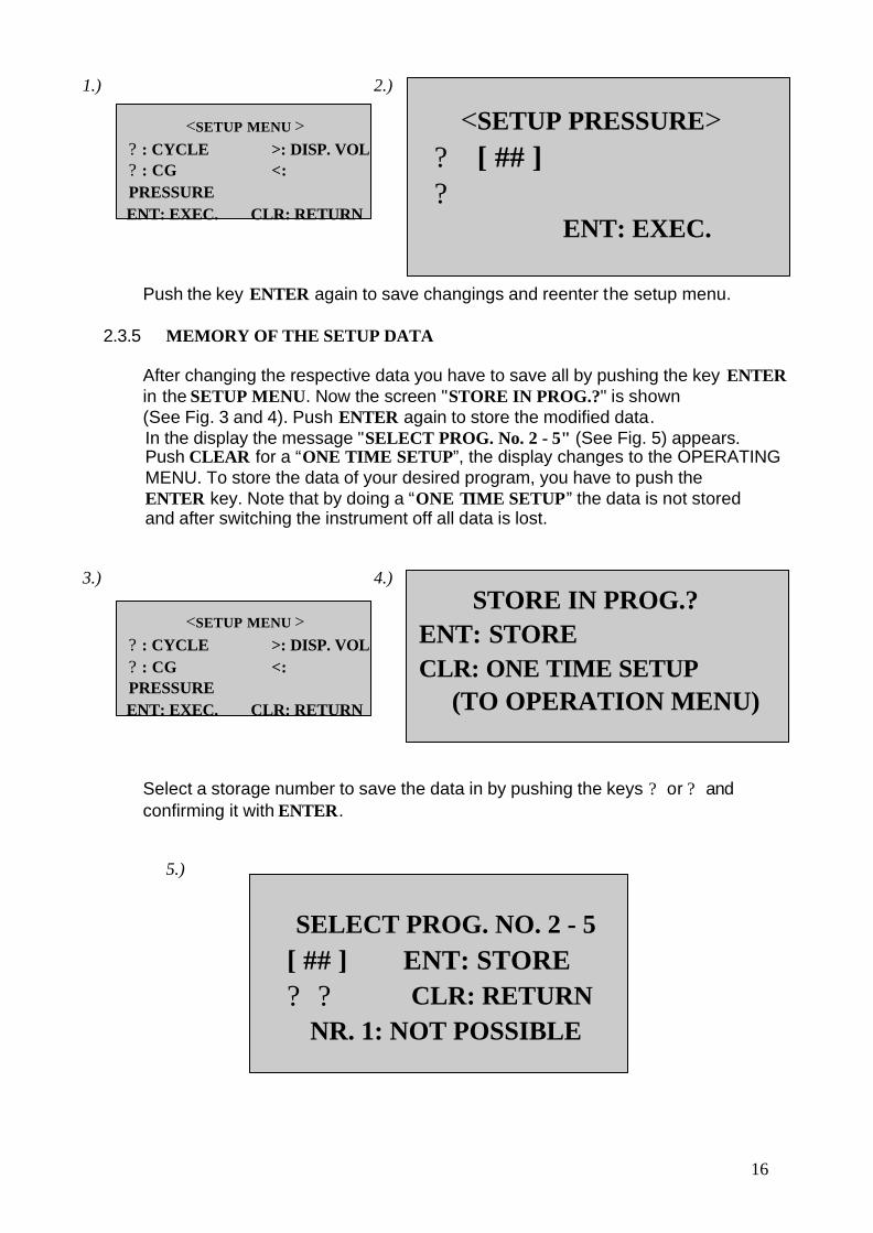
Push the key ENTER again to save changings and reenter the setup menu.
2.3.5 MEMORY OF THE SETUP DATA
After changing the respective data you have to save all by pushing the key ENTER in the SETUP MENU. Now the screen "STORE IN PROG.?" is shown (See Fig. 3 and 4). Push ENTER again to store the modified data. In the display the message "SELECT PROG. No. 2 - 5" (See Fig. 5) appears. Push CLEAR for a “ONE TIME SETUP”, the display changes to the OPERATING MENU. To store the data of your desired program, you have to push the ENTER key. Note that by doing a “ONE TIME SETUP” the data is not stored and after switching the instrument off all data is lost.
3.)
<SETUP MENU > ? : CYCLE >: DISP. VOL ? : CG <: PRESSURE ENT: EXEC. CLR: RETURN
4.)
STORE IN PROG.? ENT: STORE CLR: ONE TIME SETUP (TO OPERATION MENU)
Select a storage number to save the data in by pushing the keys ? or ? and confirming it with ENTER.
5.)
SELECT PROG. NO. 2 - 5 [ ## ] ENT: STORE ? ? CLR: RETURN
NR. 1: NOT POSSIBLE
16

The system confirms your program settings with the following screen: (See Fig. 6). The message dissappears automatically after approx. 3 seconds and display changes to SETUP MENU.
6.)
STORED ON PROG. NO. #
The system will warn you in case of an already occupied program with the following screen (See Fig. 7): Please push ENTER key if you really want to overwrite the data.
7.)
SELECTED PROG. NO. # IS IN USE. OVERWRITE? ENT: EXEC. CLR: RETURN
17
If you confirm "OVERWRITING?" by pushing the ENTER key, Fig. 6 appears in the display. The screen dissappears automatically after approx. 3 seconds and changes to SETUP MENU.
The parameters set and stored in this chapter function as presetting for your programs and may be still changed later during the operation, to obtain optimal coverslipping results.
3
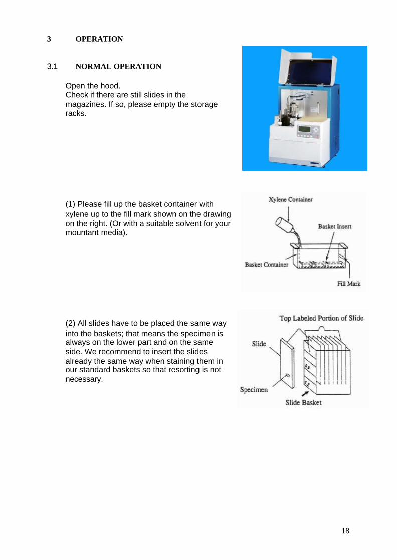
3.1
OPERATION
NORMAL OPERATION
Open the hood. Check if there are still slides in the magazines. If so, please empty the storage racks.
(1) Please fill up the basket container with xylene up to the fill mark shown on the drawing on the right. (Or with a suitable solvent for your mountant media).
(2) All slides have to be placed the same way into the baskets; that means the specimen is always on the lower part and on the same side. We recommend to insert the slides already the same way when staining them in our standard baskets so that resorting is not necessary.
18
19
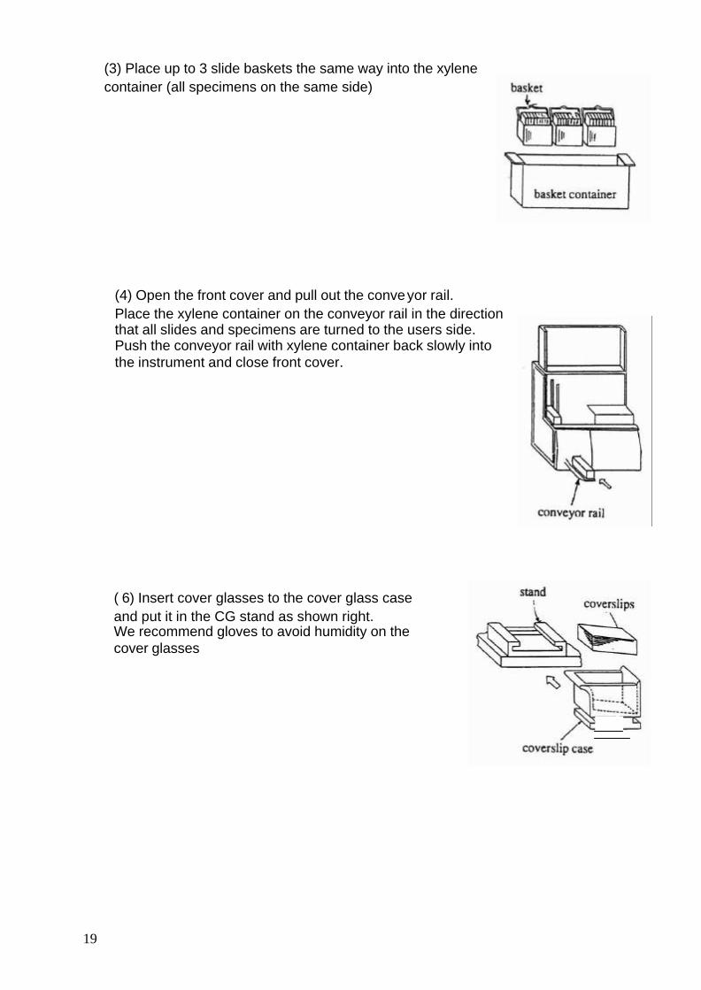
(3) Place up to 3 slide baskets the same way into the xylene container (all specimens on the same side)
(4) Open the front cover and pull out the conveyor rail. Place the xylene container on the conveyor rail in the direction that all slides and specimens are turned to the users side. Push the conveyor rail with xylene container back slowly into the instrument and close front cover.
( 6) Insert cover glasses to the cover glass case and put it in the CG stand as shown right. We recommend gloves to avoid humidity on the cover glasses

(6) The coverslipping procedure can be adjusted according to the size of the used cover glass. In addition to that you have to adjust the slidable mechanism on the CG head at the markings for it as follows:
? ? ?
24 x 40 mm: 24 x 50 mm: 24 x 55 or 60 mm:
to the right in the middle
to the left
(7) Place the dispenser into the dispenser stand (8) Set 3 empty storage racks into the elevator and put an empty purge cap into the holder at the fork. Close hood and front cover. If the key START lights up, you can push it to begin a job. With this quick start you start the program which was used the last time offered to you by the menu. Go on with all steps, explained in chapter 3.2 for program selection.
20
3.2. PROGRAM SELECTION
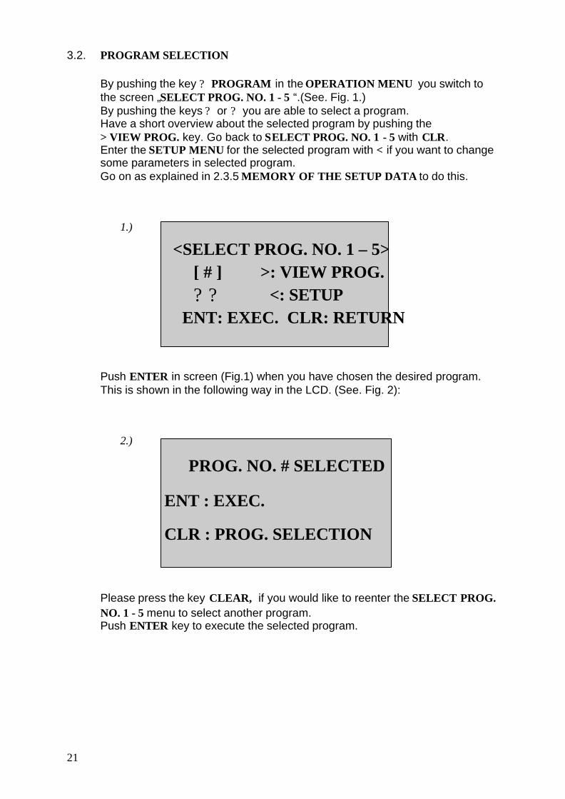
By pushing the key ? PROGRAM in the OPERATION MENU you switch to the screen „SELECT PROG. NO. 1 - 5 “.(See. Fig. 1.) By pushing the keys ? or ? you are able to select a program. Have a short overview about the selected program by pushing the > VIEW PROG. key. Go back to SELECT PROG. NO. 1 - 5 with CLR. Enter the SETUP MENU for the selected program with < if you want to change some parameters in selected program. Go on as explained in 2.3.5 MEMORY OF THE SETUP DATA to do this.
1.)
<SELECT PROG. NO. 1 – 5> [ # ] >: VIEW PROG. ? ? <: SETUP
21
ENT: EXEC. CLR: RETURN
Push ENTER in screen (Fig.1) when you have chosen the desired program. This is shown in the following way in the LCD. (See. Fig. 2):
2.)
PROG. NO. # SELECTED
ENT : EXEC.
CLR : PROG. SELECTION
Please press the key CLEAR, if you would like to reenter the SELECT PROG. NO. 1 - 5 menu to select another program. Push ENTER key to execute the selected program.
3.3 STARTING THE COVERSLIPPING PROCEDURE
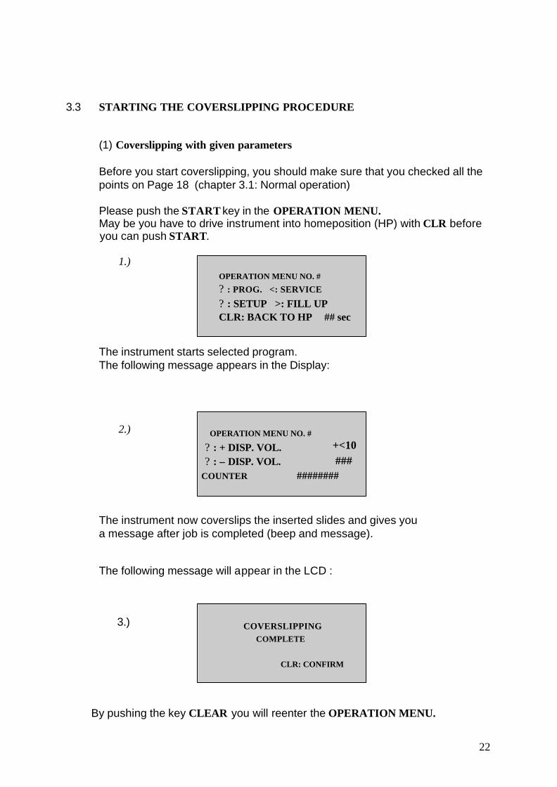
(1) Coverslipping with given parameters
Before you start coverslipping, you should make sure that you checked all the points on Page 18 (chapter 3.1: Normal operation)
Please push the START key in the OPERATION MENU. May be you have to drive instrument into homeposition (HP) with CLR before you can push START.
1.) OPERATION MENU NO. #
? : PROG. <: SERVICE
? : SETUP >: FILL UP CLR: BACK TO HP ## sec
The instrument starts selected program. The following message appears in the Display:
2.)
OPERATION MENU NO. #
? : + DISP. VOL. ? : – DISP. VOL.
+<10 ###
COUNTER ########
The instrument now coverslips the inserted slides and gives you a message after job is completed (beep and message).
The following message will appear in the LCD :
3.)
COVERSLIPPING
COMPLETE
CLR: CONFIRM
By pushing the key CLEAR you will reenter the OPERATION MENU.
22

(2) Changing parameters during operation
In order to receive an optimal result, the data can be optimized during operation. CYCLE TIME , COVERGLASS SIZE, MOUNTANT MEDIA QUANTITY and COVERING PRESSURE can be optimated.
You can adjust the MOUNTANT MEDIA QUANTITY during the operation (See Fig. 2), with the key ? to increase the delivery quantity, and ? to lower it. By pushing the keys ? or ? in combination with the key < the delivery quantity can be changed by the factor 10. Furthermore you can set the other parameters during the operation, as explained here :
CLEAR>OPERATING-MENUE>PROGRAMSELECTION>ADJUST
Proceed in the following way: At first test 3 – 4 empty slides after changing the parameters. Push the key STOP to interrupt the coverslipping procedure, wait till machine stopped in parking position and control the coverslipped quality of the slides in the storage rack by opening the hood. If you have to change the parameters again, then please push the key CLEAR, select the nessecary parameters and adjust the values. Confirm the new settings with the key ENTER. Press the key ENTER again to execute the changes.
2.)
OPERATION MENU NO. # ? : + DISP. VOL. +<10 ? : – DISP. VOL. 80
COUNTER 000000 23

3.4 MODIFYING STORED DATA
Push the key < SETUP in the SELECT PROG. NO 1 - 5 menu. The screen SETUP MODIFICATION appears in the LCD.
1.)
<SELECT PROG. NO. 1 – 5> [ # ] >: CONFIRM
? ? <: SETUP ENT: EXEC. CLR: RETURN
2.)
<SETUP MODIFICATION> ? : CYCLE >: DISP. VOL ? : CG <: PRESSURE ENT: EXEC. CLR: RETURN
Now you can choose the data to be changed. For more information read chapter 2.3, page 13.
3.5 INTERRUPTING THE COVERSLIPPING PROCESS
(1) Press the key STOP to interrupt the coverslipping procedure. You have to wait until instrument has reached parking position before you open the front door or cover. If you want to restart the job later, you only have to press the key RESTART.
By opening the cover or the front door during the coverslipping procedure the instrument stops immediately. In this case, RESTART is not possible, because there’s no definated position. In case of an opened top cover and / or front door you’ll have to follow the instructions in the display.
(2) If you have to stop the instrument immediately in case of a problem, you have to push the key A (EMERGENCY) for an emergency stop.
In this case, RESTART is not possible, because there’s no definated position and you have to be sure to have the problem causing parts removed or repaired (remove broken slideglass or whatever). After that you can press the key CLEAR so instrument can go into its initial position. Now, you may start a new coverslipping procedure.
3.6 SWITCHING THE INSTRUMENT OFF
Press the key POWER to switch the instrument off. If the instrument is not used for a longer period, you should turn the power switch on the back of the instrument into 0 position.
24

4
ERROR MESSAGES
4.1 Coverglass
4.1.1 ADD COVERGLASS
(Info message: SMALL NUMBER OF COVERGLASS) If at Start of coverslipping there are less than at least 70 coverglasses inside of CG case, instrument detects it and gives the message ADD COVERGLASS (s.fig. down) but keeps running the process. After some time the message text disappears. The alarm tone can be muted by pressing the key CLEAR. The coverslipping goes on till CG case is total empty. By pressing the key STOP you may interrupt the process and after reaching the parking position you can open the top cover and add coverglasses. After this you may restart the instrument by pushing the RESTART key.
ADD COVERGLASS
CLR : MUTE STOP : PAUSE
25

4.1.2
COVERGLASS BROKEN
If a broken coverglass is detected, you will get the following message in the display:
COVERGLASS BROKEN REMOVE BROKEN COVERGLASS
CLR: RETURN
Press the key CLEAR, to terminate the alarm. Remove broken coverglass with all fragments (note: the fragments may block the remaining coverglasses in the CG case). Remove the slide from the storage fork if necessary and put it back into the xylene container (in addition to that you move the container on the conveyor rail manually). If coverglass was not broken, you may have a problem with the vacuum circuit. Check vacuum pad and vacuum rod. (Pad has to be soft and not glued or porous !) If vacuum pad is glued, there may also be stucked mountant media inside of vacuum rod or tube that has to be removed first! (This may happen when coverglas breaks on slide and media gets to the vacuum pad and is sucked in). At last there may also be a problem with the vacuum valve causing this problem. After having closed the front and the top covers the instrument signals RESTART to you by flashing the key. The interrupted process can be taken up again by pressing the key RESTART. (Be sure you do not open the covers before instrument has reached parking position!)
26

4.1.3 CG VACUUM ERROR
The instrument tries to pick up a cover glass for 3 times. If no coverglass is detected, instrument stops the process and the following message appears in the display:
CG VACUUM ERROR. CHECK CG AND VACUUM PAD
CLR: RETURN
This message already shows you, that there may be 2 problems that cause the alarm. So you have to check the following 2 points.
(1) No coverglass
Press the key CLEAR, to determine the alert. After the MCS has stopped its movement you can open the hood and add new coverglasses. After closing the cover again you can press the key RESTART to continue the interrupted procedure.Please note that you can only open the hood if the instrument has already stopped in its parking position. If the cover is opened, before the instrument has stopped the positioning, you cannot RESTART the instrument. In this case you first have to look if there’s a slide in the finger, remove it by holding the slide by hand and press the key FINGER. Finger opens so you can remove the slide and put it back into the xylene container.(in addition to that you move the container on the conveyor rail manually). If a slide should be still on the fork put it back into container. Further you have to remove all covered slides from the storage racks and reinsert the emptied racks. Now you may press the key CLEAR in the OPERATION MENU. The Unit is now started to reach its initial position and then has to be started again with the key START.
(2) Dirty coverglass or incorrect sucking procedure.
Like in the case of the error No coverglass you have to press the key CLEAR, to stop the alert. After the MCS has stopped its movement you can open the hood and check if coverglass is dirty or vacuum pad is not OK. (Be sure you do not open the covers before instrument has reached parking position!) If coverglass is OK and not dirty, you may have a problem with the vacuum circuit. Check vacuum pad. The pad has to be soft and not porous or glued, otherwise it will be too inflexible to softly pick up a coverglass. The same phenomen may appear if some tube connections are not dense enough or air can run inside the system in other ways. So be sure to have a small check of all visible parts of this. After having removed all problems you can close the cover again push the key RESTART to continue the interrupted procedure.
27

4.2 SLIDES
4.2.1 SG PICK UP ERROR
If the finger did not put a slide correctly to coverslip position, the following message appears:
SG PICK UP ERROR CHECK SG AND FINGER
CLR: EXEC.
Please push the key CLEAR, to finish the alarm. Wait until unit stopped. Remove the incorrect slide from the finger if necessary and put it back into xylene container. The error message may be caused by the fact that the finger could not pick up a slide correctly. Check if slides and baskets are inserted correctly into container. Press the key RESTART, to continue the job. If the error message appears again, please check the following possibilities:
1. The slide basket does not stand correctly in the container. Solution: Position basket correctly.
2. There may be broken glass under the slides or under the insert in the xylene container. Solution: Remove the glass. Please make sure that there are no fragments inside of the container. Empty xylene container and clean it if necessary.
3. The slide baskets are bent. Solution: Sort the damaged slide basket and replace it by an intact/new one
4. The grab finger is dirty. Solution: Clean the grab finger. Brush it with xylene if mountant media dried on the finger.
If you are not able to solve this problem, you should call the technical customer service.
28
4.2
4.2.2
SG STORAGE ERROR
29
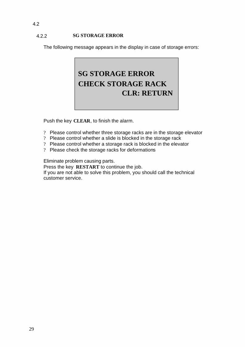
The following message appears in the display in case of storage errors:
SG STORAGE ERROR CHECK STORAGE RACK
CLR: RETURN
Push the key CLEAR, to finish the alarm.
? Please control whether three storage racks are in the storage elevator ? Please control whether a slide is blocked in the storage rack ? Please control whether a storage rack is blocked in the elevator ? Please check the storage racks for deformations
Eliminate problem causing parts. Press the key RESTART to continue the job. If you are not able to solve this problem, you should call the technical customer service.

4.3 BATTERY
Warning reference: With the following error message in the display, the unit warns you to change the battery for the back up software of the instrument now. Let the battery be changed regularly to ensure that in worst case your data is not lost.
Please contact the technical customer service in this case, to ensure to have no data lost while changing the battery.
BATTERY POWER LOW ON CONTROL DEVICE. OPERATING IN FACTORY DEFAULT MODE. CLR: RTN
REPLACE BATTERY ON CONTROL DEVICE
30

4.4 ERROR CODE messages
If instrument has an error listed in chapter 3.9 on Page. 33, then the following message will appear in the display. More error details can be found in the error code list.
ERROR. ERROR CODE [ ### ]
CLR: CONFIRM
Push the CLEAR button. The following message will appear in the display
MEMORIZE ERROR. CODE ### READ INSTRUCTION MANUAL
ENT: CONFIRM Please contact technical customer service for more information and help in this case.
31

4.5
ERRORCODE-LIST
Code Position troubled 101 Conveyor
102 Conveyor
103 Conveyor
201 Elevator
202 Elevator
301 Mainshaft
302 Mainshaft 303 Mainshaft 401 CG-Head and fork 402 CG-Head and fork 403 CG-Head and fork 404 CG-Head and fork 501 Dispenser pump 502 Dispenser pump 601 Arm 602 Arm 603 Arm 701 Finger
901 Complete unit
Description It takes more then 1 minute, till xylene container has reached back (home) position. Container is not pulled in, perhaps rails slipping / blocked / don’t move. Please check xylene container for deformations and dirt. (Also check conveyor rails) Conveyor rail overruns home position. (happens when pushing in by hand too far) Basket container detected but slide glass is not detected. Basket container is not loaded but Slide glass detected. Upper end and / or lower end sensor has problem Time out during elevator movement, motor slips over / does not turn Error Main Shaft too high / too low (limitswitch) Error sensors Main Shaft up / down Time out error. Push Rod blocked in up position or hood / frontdoor switches not correctly set and safety relay for mainshaft power supply not switched. Error CG-Head and fork driver unit Sensor for CG head detects error Storage fork sensor detects error Time out error. Fork could not reach position because of bent rack, already existing or stacked slides in rack or on fork, or because of blocked bearings Error driver unit Pump sensors have error Error driver unit Arm sensor detection error Time out error during arm movement Finger movement error (open/close), may happen after crash (sensor / mechanic in finger deformed / blocked) Cycletime not within programmed range
32
5
5.1.
5.2
33
MAINTENANCE AND SERVICE
GENERAL
The coverslipping machine MCS is a sensitive, electromechanical instrument. In order to avoid defects in the
electronic circuit or malfunctions, this manual has to be read and obeyed exactly. The disposal of used solvents (and charcoal filters) has to be done in respective of valid specific laws.
SERVICE
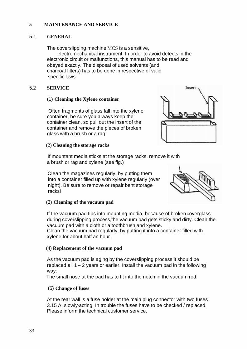
(1) Cleaning the Xylene container
Often fragments of glass fall into the xylene container, be sure you always keep the container clean, so pull out the insert of the container and remove the pieces of broken glass with a brush or a rag.
(2) Cleaning the storage racks
If mountant media sticks at the storage racks, remove it with a brush or rag and xylene (see fig.)
Clean the magazines regularly, by putting them into a container filled up with xylene regularly (over
night). Be sure to remove or repair bent storage racks!
(3) Cleaning of the vacuum pad
If the vacuum pad tips into mounting media, because of broken coverglass during coverslipping process,the vacuum pad gets sticky and dirty. Clean the vacuum pad with a cloth or a toothbrush and xylene. Clean the vacuum pad regularly, by putting it into a container filled with xylene for about half an hour.
(4) Replacement of the vacuum pad
As the vacuum pad is aging by the coverslipping process it should be replaced all 1 – 2 years or earlier. Install the vacuum pad in the following way: The small nose at the pad has to fit into the notch in the vacuum rod.
(5) Change of fuses
At the rear wall is a fuse holder at the main plug connector with two fuses 3.15 A, slowly-acting. In trouble the fuses have to be checked / replaced. Please inform the technical customer service.