maurer seismic protection systems · page 1 / maurer seismic protection systems j structural 1....
TRANSCRIPT
10.09.2001/VLE
MAURER Seismic Protection Systems
Technical Information and Dimensions
10.09.2001/VLE
MAURER Seismic Protection Systems
CONTENTS 1. Introduction 1 2. Concepts for seismic protection 2 2.1. ENERGY SHARING 2 2.2. ENERGY MITIGATION 3 3. Energy approach concept for optimal seismic protection 5 4. The way to the ideal seismic protection system 7 5. Technical description of shock transmission units (MSTU/MSTL) 8 5.1. MSTU - Standard shock transmission unit 8 5.2. MSTL – Shock transmission unit with force limiter 9 5.3. General characteristics of MSTU and MSTL 10 5.4. Dimensions and anchoring of MSTU and MSTL 11 6. Technical description of seismic dampers (MHD) 12
6.1. MHD – Seismic damper 12 6.2. Dimensions and anchoring of MHD 14
7. Technical description of seismic isolators (VS) 15 7.1. VS - Seismic isolators 15 7.2. Dimensions of V2S seismic isolators 16 7.3. Dimensions of VE2S seismic isolators 17
8. Technical information for DS and DS-F type seismic swivel-joist expansion joint 18
9. General information for a non-linear time history analysis 20 10. Testing of seismic protection devices 21
Page 1 / MAURER Seismic Protection Systems
1. Introduction The technical state of the art allows structures of any kind to be adapted to different load cases, e.g. traffic, wind, seismic impacts, etc.. Therefrom, the appearing stresses are distributed in as far as possible a well-proportioned way over the entire structure or they are even essentially reduced from the very beginning in addition by special isolating and damping devices.
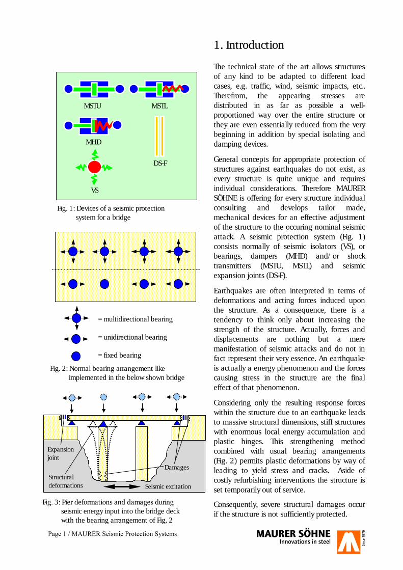
General concepts for appropriate protection of structures against earthquakes do not exist, as every structure is quite unique and requires individual considerations. Therefore MAURER SÖHNE is offering for every structure individual consulting and develops tailor made, mechanical devices for an effective adjustment of the structure to the occuring nominal seismic attack. A seismic protection system (Fig. 1) consists normally of seismic isolators (VS), or bearings, dampers (MHD) and/or shock transmitters (MSTU, MSTL) and seismic expansion joints (DS-F).
Earthquakes are often interpreted in terms of deformations and acting forces induced upon the structure. As a consequence, there is a tendency to think only about increasing the strength of the structure. Actually, forces and displacements are nothing but a mere manifestation of seismic attacks and do not in fact represent their very essence. An earthquake is actually a energy phenomenon and the forces causing stress in the structure are the final effect of that phenomenon.
Considering only the resulting response forces within the structure due to an earthquake leads to massive structural dimensions, stiff structures with enormous local energy accumulation and plastic hinges. This strengthening method combined with usual bearing arrangements (Fig. 2) permits plastic deformations by way of leading to yield stress and cracks. Aside of costly refurbishing interventions the structure is set temporarily out of service.
Consequently, severe structural damages occur if the structure is not sufficiently protected.
MSTU MSTL MHD
DS-F VS Fig. 1: Devices of a seismic protection system for a bridge
Fig. 3: Pier deformations and damages during seismic energy input into the bridge deck with the bearing arrangement of Fig. 2
= multidirectional bearing
= unidirectional bearing = fixed bearing
Fig. 2: Normal bearing arrangement like implemented in the below shown bridge
Damages
Seismic excitation
Expansion joint
Structural deformations
Page 2 / MAURER Seismic Protection Systems
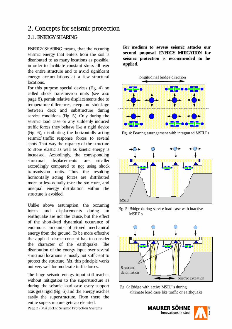
2.1. ENERGY SHARING ENERGY SHARING means, that the occuring seismic energy that enters from the soil is distributed to as many locations as possible, in order to facilitate constant stress all over the entire structure and to avoid significant energy accumulations at a few structural locations. For this purpose special devices (Fig. 4), so called shock transmission units (see also page 8), permit relative displacements due to temperature differences, creep and shrinkage between deck and substructure during service conditions (Fig. 5). Only during the seismic load case or any suddenly induced traffic forces they behave like a rigid device (Fig. 6), distributing the horizontally acting seismic/traffic response forces to several spots. That way the capacity of the structure to store elastic as well as kinetic energy is increased. Accordingly, the corresponding structural displacements are smaller accordingly compared to not using shock transmission units. Thus the resulting horizontally acting forces are distributed more or less equally over the structure, and unequal energy distribution within the structure is avoided. Unlike above assumption, the occurring forces and displacements during an earthquake are not the cause, but the effect of the short-lived dynamical occurance of enormous amounts of stored mechanical energy from the ground. To be more effective the applied seismic concept has to consider the character of the earthquake. The distribution of the energy input over several structural locations is mostly not sufficient to protect the structure. Yet, this principle works out very well for moderate traffic forces.
The huge seismic energy input still reaches without mitigation to the superstructure as during the seismic load case every support axis gets rigid (Fig. 6) and the energy reaches easily the superstructure. From there the entire superstructure gets accelerated.
For medium to severe seismic attacks our second proposal ENERGY MITIGATION for seismic protection is recommended to be applied.
Fig. 4: Bearing arrangement with integrated MSTU´s
longitudinal bridge direction
Fig. 5: Bridge during service load case with inactive MSTU`s
MSTU
2. Concepts for seismic protection
Fig. 6: Bridge with active MSTU´s during ultimate load case like traffic or earthquake
Structural deformation
Seismic excitation
Page 3 / MAURER Seismic Protection Systems
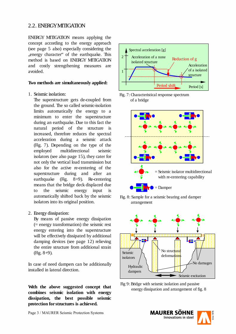
2.2. ENERGY MITIGATION ENERGY MITIGATION means applying the concept according to the energy approach (see page 5 also) especially considering the „energy character“ of the earthquake. This method is based on ENERGY MITIGATION and costly strengthening measures are avoided. Two methods are simultaneously applied: 1. Seismic isolation:
The superstructure gets de-coupled from the ground. The so called seismic-isolation limits automatically the energy to a minimum to enter the superstructure during an earthquake. Due to this fact the natural period of the structure is increased, therefore reduces the spectral acceleration during a seismic attack (Fig. 7). Depending on the type of the employed multidirectional seismic isolators (see also page 15), they cater for not only the vertical load transmission but also for the active re-centering of the superstructure during and after an earthquake (Fig. 8+9). Re-centering means that the bridge deck displaced due to the seismic energy input is automatically shifted back by the seismic isolators into its original position.
2. Energy dissipation:
By means of passive energy dissipation (= energy transformation) the seismic rest energy entering into the superstructure will be effectively dissipated by additional damping devices (see page 12) relieving the entire structure from additional strain (Fig. 8+9).
In case of need dampers can be additionally installed in lateral direction. With the above suggested concept that combines seismic isolation with energy dissipation, the best possible seismic protection for structures is achieved.
Period [s]
Spectral acceleration [g]
2 1
Acceleration of a none isolated structure
Acceleration of a isolated structure
Fig. 7: Characteristical response spectrum of a bridge
Fig 9: Bridge with seismic isolation and passive energy dissipation and arrangement of fig. 8
Fig. 8: Sample for a seismic bearing and damper arrangement
= Seismic isolator multidirectional with re-centering capability = Damper
No damages
Seismic excitation
No structural deformations
Hydraulic dampers
Seismic isolators
Period shift
Reduction of g
Page 4 / MAURER Seismic Protection Systems
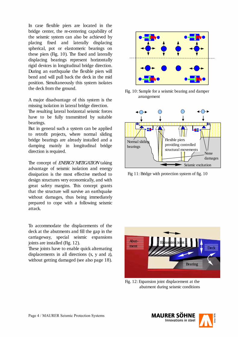
In case flexible piers are located in the bridge center, the re-centering capability of the seismic system can also be achieved by placing fixed and laterally displacing spherical, pot or elastomeric bearings on these piers (Fig. 10). The fixed and laterally displacing bearings represent horizontally rigid devices in longitudinal bridge direction. During an earthquake the flexible piers will bend and will pull back the deck in the mid position. Simultaneously this system isolates the deck from the ground. A major disadvantage of this system is the missing isolation in lateral bridge direction. The resulting lateral horizontal seismic forces have to be fully transmitted by suitable bearings. But in general such a system can be applied to retrofit projects, where normal sliding bridge bearings are already installed and a damping mainly in longitudinal bridge direction is required. The concept of ENERGY MITIGATION taking advantage of seismic isolation and energy dissipation is the most effective method to design structures very economically, and with great safety margins. This concept grants that the structure will survive an earthquake without damages, thus being immediately prepared to cope with a following seismic attack. To accommodate the displacements of the deck at the abutments and fill the gap in the carriageway, special seismic expansions joints are installed (Fig. 12). These joints have to enable quick alternating displacements in all directions (x, y and z), without getting damaged (see also page 18).
Expansion joint Deck
Abut-ment
Bearing
Fig. 10: Sample for a seismic bearing and damper arrangement
None damages
Seismic excitation
Normal sliding bearings
Fig 11: Bridge with protection system of fig. 10
Fig. 12: Expansion joint displacement at the abutment during seismic conditions
Flexible piers providing controlled structural movements

Page 5 / MAURER Seismic Protection Systems
As already mentioned in chapter 2.2. an earthquake is an energy phenomenon and therefore this energy character should be considered to achieve the best possible seismic protection for the structure. Without any seismic protection system the seismic energy is entering the structure very concentrated at the fixed axis, thus hitting the structure mainly at one single axis (Fig. 13).
By means of shock transmission units the entering energy is distributed to several spots within the structure (Fig. 14). The energy input into the structure is still in same magnitude like without STU´s – no mitigation – but now the energy is spread over the entire structure in more or less equal portions.
By implementing additional seismic isolation and also energy dissipation capability, less energy is entering the structure (Fig. 15), and the remaining energy amount entering the structure is effectively mitigated. The principles of physics that govern the effects of dissipation on the control of dynamic phenomena were studied more than two centuries ago (D´Alembert, Traité de dynamique, 1743). Nonetheless, their practical application has come about much later and within a much different time-frame in several sectors of engineering. The sector that was the first to adopt such damping technologies was the military (France, 1897) and let the country enjoy world supremacy in artillery for the better part of a decade. In not too short order the automobile industry followed in these steps by using dampers in their suspension systems to ensure the comfort and the stability of motor vehicles. In 1956 Housner already suggested an energy-based design for structures. Akiyama (1985), Uang (1988) and Bertero (1988) made a valuable contribution to the development of the aspects of an energy-based approach, which presently meets with great concensus.
3. Energy approach concept for optimum seismic protection
Fig. 13: Without seismic protection system seismic energy is penetrating into the structure
Damages
Seismic excitation
Structural deformations
Induced energy
Great deck displacements
Fig. 14: Seismic energy is penetrating into the structure fitted with STU´s for energy sharing
Structural deformation
Seismic excitation
Deck displacements
Induced energy
Fig. 15: Minimized seismic energy penetration by implementing seismic-isolation (isolators) and energy dissipation (dampers)
None damages
Seismic excitation
None structural deformations
Minimum deck displacements
Induced energy
Page 6 / MAURER Seismic Protection Systems
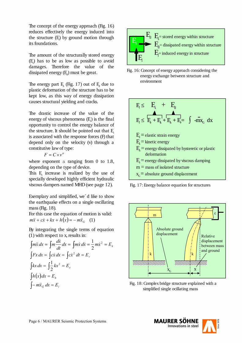
The concept of the energy approach (Fig. 16) reduces effectively the energy induced into the structure (Ei) by ground motion through its foundations. The amount of the structurally stored energy (Es) has to be as low as possible to avoid damages. Therefore the value of the dissipated energy (Ed) must be great. The energy part Eh (Fig. 17) out of Ed due to plastic deformation of the structure has to be kept low, as this way of energy dissipation causes structural yielding and cracks. The drastic increase of the value of the energy of viscous phenomena (Ev) is the final opportunity to control the energy balance of the structure. It should be pointed out that Ev is associated with the response forces (F) that depend only on the velocity (v) through a constitutive law of type: �vCF �� where exponent a ranging from 0 to 1.8, depending on the type of device. This Ev increase is realized by the use of specially developed highly efficient hydraulic viscous dampers named MHD (see page 12). Exemplary and simplified, we´d like to show the earthquake effects on a single oscillating mass (Fig. 18). For this case the equation of motion is valid:
� � Gxmxhkxxcxm ����� ����� (1)
By integrating the single terms of equation (1) with respect to x, results in:
� � � ���� kExmxdxmdxdtxdmdxxm 2
21
����
��
� �� ��� vEdtxcdxxcdxFx 2��
� � �� eEkxdxkx 2
21
� �� � hEdxxh
� �� iG Edxxm ��
Ei � Es + Ed
Ei � Ee + Ek + Eh + Ev= ∫ -mxG dx Ee = elastic strain energy
Ek = kinetic energy
Eh = energy dissipated by hysteretic or plastic deformation
Ev = energy dissipated by viscous damping
m = mass of isolated structure
xG = absolute ground displacement
Ei
Ed Es
Es= stored energy within structure
Ed= dissipated energy within structure
Ei= induced energy in structure
Fig. 16: Concept of energy approach considering the energy exchange between structure and environment
Fig. 17: Energy balance equation for structures
Fig. 18: Complex bridge structure explained with a simplified single ocillating mass
k
m
k
c
xG x
Absolute ground displacement Relative
displacement between mass and ground
Page 7 / MAURER Seismic Protection Systems
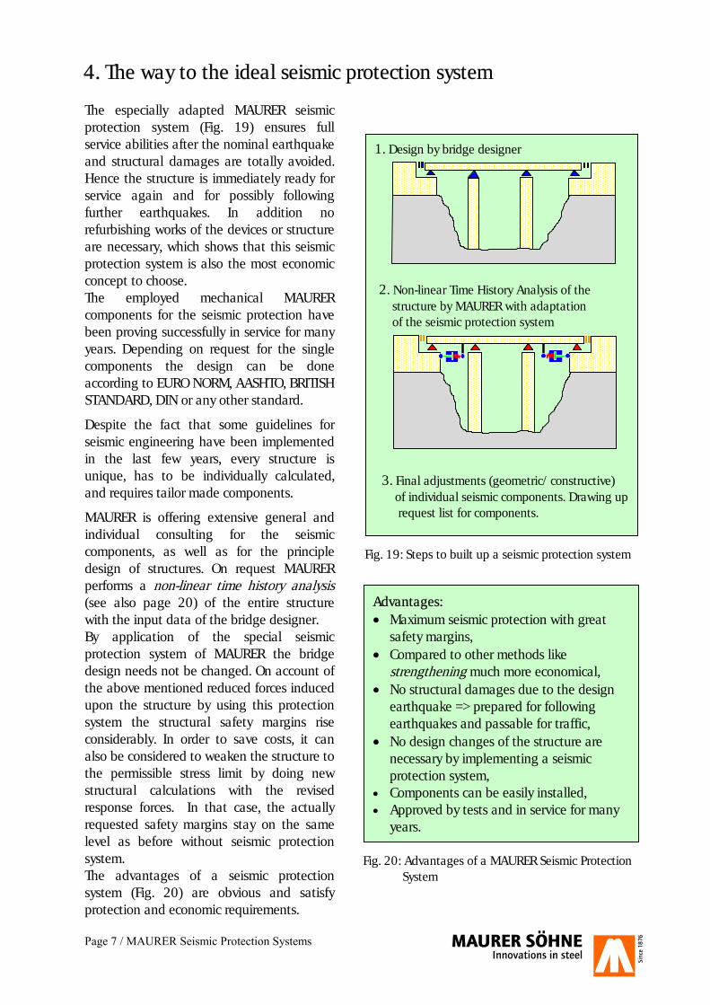
The especially adapted MAURER seismic protection system (Fig. 19) ensures full service abilities after the nominal earthquake and structural damages are totally avoided. Hence the structure is immediately ready for service again and for possibly following further earthquakes. In addition no refurbishing works of the devices or structure are necessary, which shows that this seismic protection system is also the most economic concept to choose. The employed mechanical MAURER components for the seismic protection have been proving successfully in service for many years. Depending on request for the single components the design can be done according to EURO NORM, AASHTO, BRITISH STANDARD, DIN or any other standard.
Despite the fact that some guidelines for seismic engineering have been implemented in the last few years, every structure is unique, has to be individually calculated, and requires tailor made components.
MAURER is offering extensive general and individual consulting for the seismic components, as well as for the principle design of structures. On request MAURER performs a non-linear time history analysis (see also page 20) of the entire structure with the input data of the bridge designer. By application of the special seismic protection system of MAURER the bridge design needs not be changed. On account of the above mentioned reduced forces induced upon the structure by using this protection system the structural safety margins rise considerably. In order to save costs, it can also be considered to weaken the structure to the permissible stress limit by doing new structural calculations with the revised response forces. In that case, the actually requested safety margins stay on the same level as before without seismic protection system. The advantages of a seismic protection system (Fig. 20) are obvious and satisfy protection and economic requirements.
.
4. The way to the ideal seismic protection system
Advantages: �� Maximum seismic protection with great
safety margins, �� Compared to other methods like
strengthening much more economical, �� No structural damages due to the design
earthquake => prepared for following earthquakes and passable for traffic,
�� No design changes of the structure are necessary by implementing a seismic protection system,
�� Components can be easily installed, �� Approved by tests and in service for many
years.
Fig. 19: Steps to built up a seismic protection system
1. Design by bridge designer
Fig. 20: Advantages of a MAURER Seismic Protection System
2. Non-linear Time History Analysis of the structure by MAURER with adaptation of the seismic protection system
3. Final adjustments (geometric/constructive) of individual seismic components. Drawing up request list for components.
Page 8 / MAURER Shock Transmission Units
5. Technical description of shock transmission units (MSTU/MSTL)
5.1. MSTU - Standard shock transmission unit
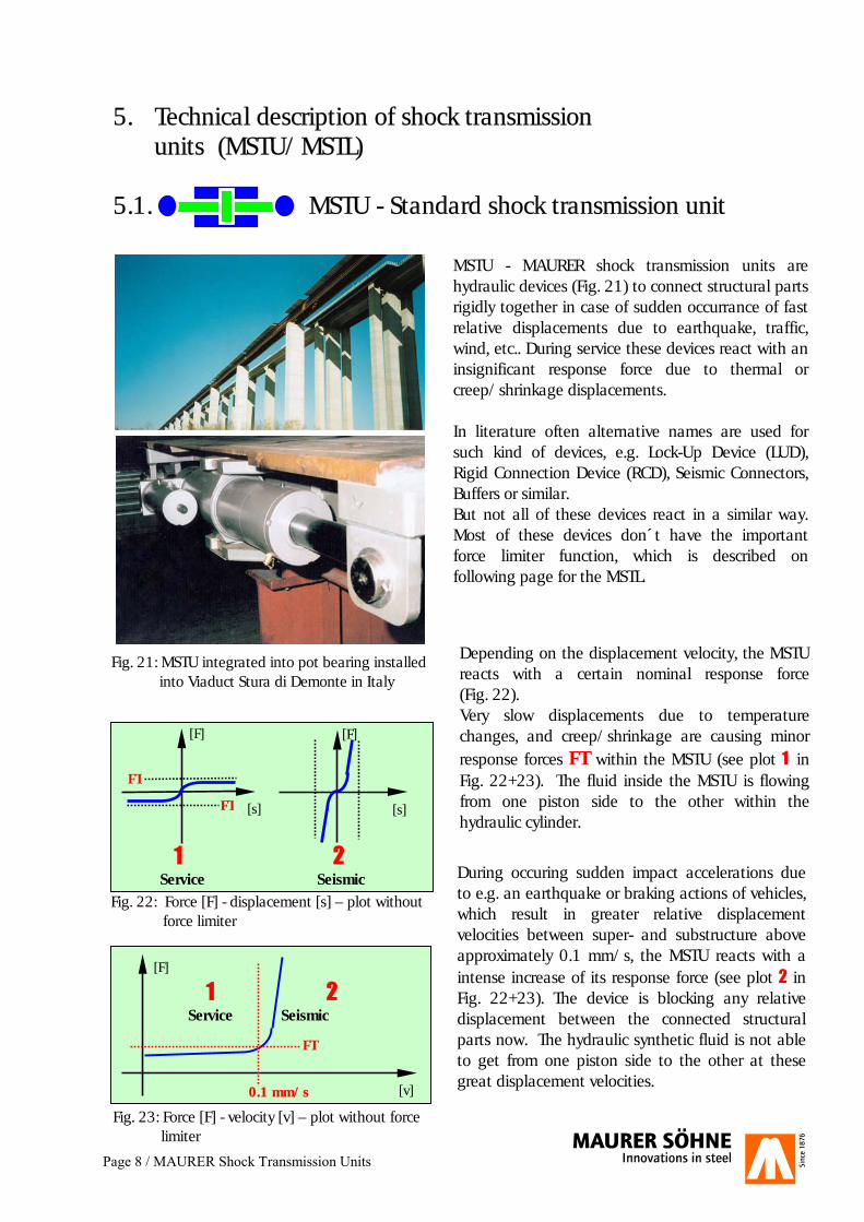
MSTU - MAURER shock transmission units are hydraulic devices (Fig. 21) to connect structural parts rigidly together in case of sudden occurrance of fast relative displacements due to earthquake, traffic, wind, etc.. During service these devices react with aninsignificant response force due to thermal or creep/shrinkage displacements. In literature often alternative names are used for such kind of devices, e.g. Lock-Up Device (LUD), Rigid Connection Device (RCD), Seismic Connectors, Buffers or similar. But not all of these devices react in a similar way. Most of these devices don´t have the important force limiter function, which is described on following page for the MSTL.
Depending on the displacement velocity, the MSTU reacts with a certain nominal response force(Fig. 22). Very slow displacements due to temperature changes, and creep/shrinkage are causing minor response forces FT within the MSTU (see plot 1 in Fig. 22+23). The fluid inside the MSTU is flowing from one piston side to the other within the hydraulic cylinder.
Fig. 23: Force [F] - velocity [v] – plot without force limiter
During occuring sudden impact accelerations due to e.g. an earthquake or braking actions of vehicles, which result in greater relative displacement velocities between super- and substructure above approximately 0.1 mm/s, the MSTU reacts with a intense increase of its response force (see plot 2 in Fig. 22+23). The device is blocking any relative displacement between the connected structural parts now. The hydraulic synthetic fluid is not able to get from one piston side to the other at these great displacement velocities.
[F]
0.1 mm/s
1 2 Service Seismic
Fig. 22: Force [F] - displacement [s] – plot without force limiter
[F]
[s]
[F]
[s]
1 2 Service Seismic
FT
FT
FT
[v]
Fig. 21: MSTU integrated into pot bearing installed into Viaduct Stura di Demonte in Italy
Page 9 / MAURER Shock Transmission Units
5.2. MSTL - Shock transmission unit with force limiter
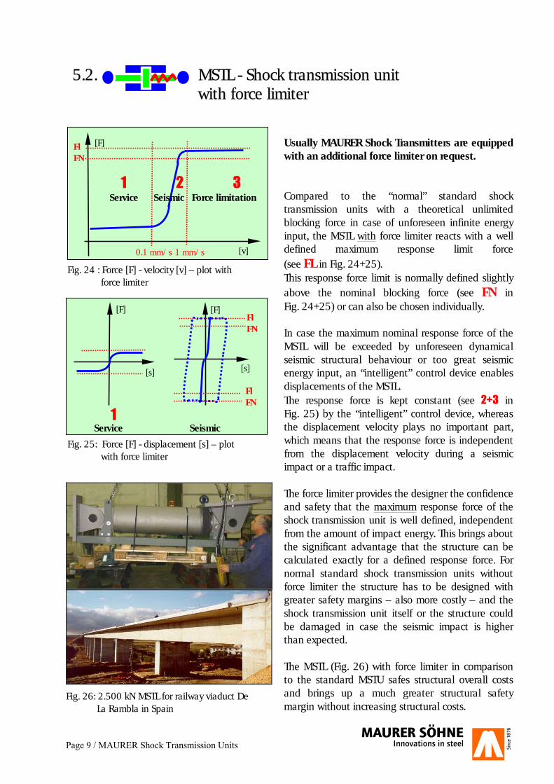
Fig. 24 : Force [F] - velocity [v] – plot with force limiter
Service Seismic
[F]
[s]
[F]
[s]
Fl FN
FlFN
1 2 3
[F]
[v]0.1 mm/s
Fl FN
1 mm/s
1 2 3 Service Seismic Force limitation
Fig. 25: Force [F] - displacement [s] – plot with force limiter
Usually MAURER Shock Transmitters are equipped with an additional force limiter on request. Compared to the “normal” standard shock transmission units with a theoretical unlimited blocking force in case of unforeseen infinite energy input, the MSTL with force limiter reacts with a well defined maximum response limit force (see FL in Fig. 24+25). This response force limit is normally defined slightly above the nominal blocking force (see FN in Fig. 24+25) or can also be chosen individually. In case the maximum nominal response force of the MSTL will be exceeded by unforeseen dynamical seismic structural behaviour or too great seismic energy input, an “intelligent” control device enables displacements of the MSTL. The response force is kept constant (see 2+3 in Fig. 25) by the “intelligent” control device, whereas the displacement velocity plays no important part, which means that the response force is independent from the displacement velocity during a seismic impact or a traffic impact. The force limiter provides the designer the confidence and safety that the maximum response force of the shock transmission unit is well defined, independent from the amount of impact energy. This brings about the significant advantage that the structure can be calculated exactly for a defined response force. For normal standard shock transmission units without force limiter the structure has to be designed with greater safety margins – also more costly – and the shock transmission unit itself or the structure could be damaged in case the seismic impact is higher than expected. The MSTL (Fig. 26) with force limiter in comparison to the standard MSTU safes structural overall costs and brings up a much greater structural safety margin without increasing structural costs.
Fig. 26: 2.500 kN MSTL for railway viaduct De La Rambla in Spain
Page 10 / MAURER Shock Transmission Units
5.3. General characteristics of MSTU and MSTL
Characteristics of a MSTU/MSTL with force limiter: �� During service conditions the devices are not
pre-tensioned and the fluid is under no significant pressure.
�� Automatic volume compensation of the fluid
caused by temperature changes is achieved without pressure increase inside the devices. Any compensation containers are located inside. On request they can also be located outside.
�� No maintenance works necessary. Visual
inspection is recommended during the periodic bridge inspections or after an earthquake respectively.
�� The devices are not prone to leaking as special
high strength hydraulic sealing rings are used like for Caterpillars, automobile industry and similar machineries. On request prove tests can be carried out.
�� Very little elasticity of 2-5% depending on
request. �� Range of temperature: -40°C to 70°C. �� Small dimensions and simple installation. �� Depending on request spherical hinges are
installed at both device ends to accommodate installation tolerances.
.
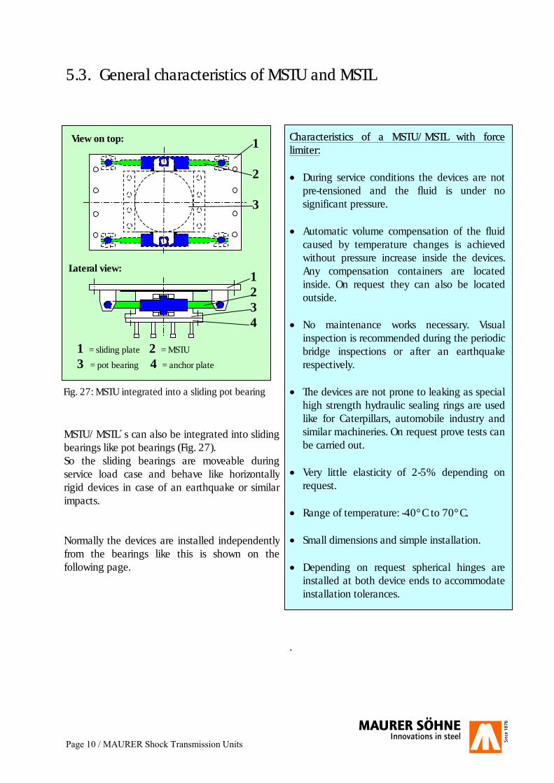
Fig. 27: MSTU integrated into a sliding pot bearing
View on top:
Lateral view:
1 2 3
1 2 3 4
1 = sliding plate 2 = MSTU
3 = pot bearing 4 = anchor plate
MSTU/MSTL´s can also be integrated into slidingbearings like pot bearings (Fig. 27). So the sliding bearings are moveable duringservice load case and behave like horizontallyrigid devices in case of an earthquake or similarimpacts. Normally the devices are installed independentlyfrom the bearings like this is shown on thefollowing page.
Page 11 / MAURER Shock Transmission Units
5.4. Dimensions and anchoring of MSTU and MSTL
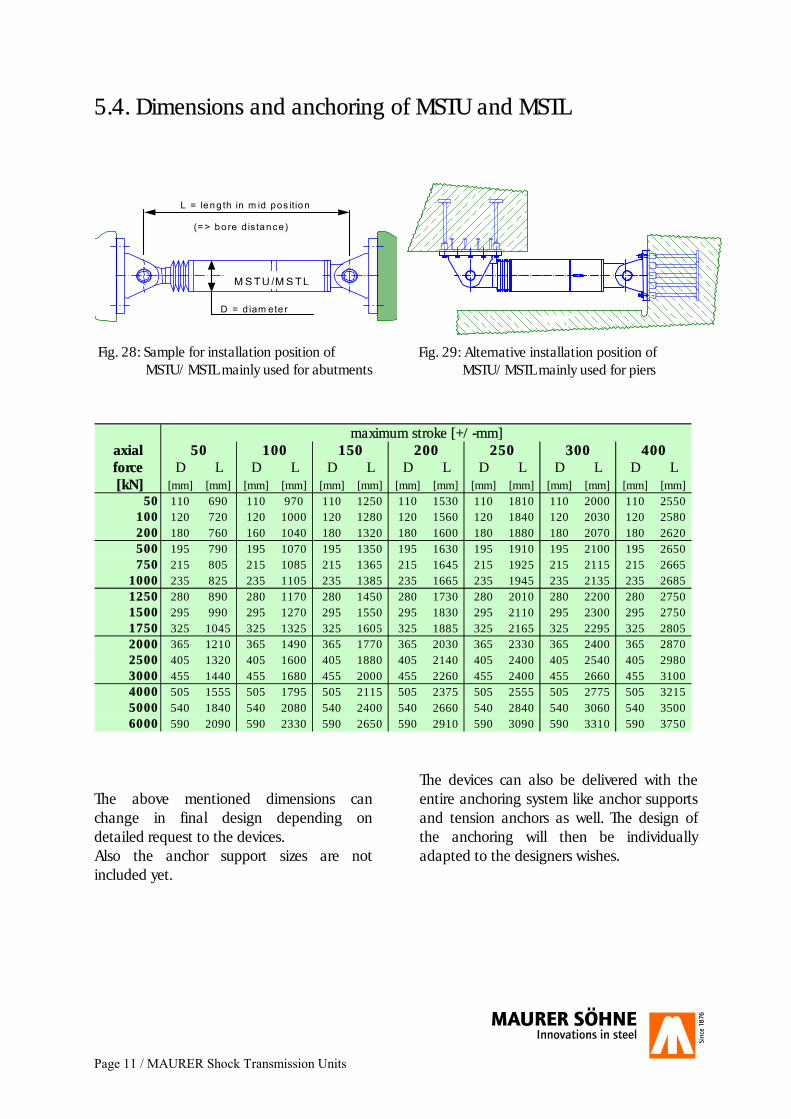
maximum stroke [+/-mm]axial 50 100 150 200 250 300 400force D L D L D L D L D L D L D L [kN] [mm] [mm] [mm] [mm] [mm] [mm] [mm] [mm] [mm] [mm] [mm] [mm] [mm] [mm]
50 110 690 110 970 110 1250 110 1530 110 1810 110 2000 110 2550100 120 720 120 1000 120 1280 120 1560 120 1840 120 2030 120 2580200 180 760 160 1040 180 1320 180 1600 180 1880 180 2070 180 2620500 195 790 195 1070 195 1350 195 1630 195 1910 195 2100 195 2650750 215 805 215 1085 215 1365 215 1645 215 1925 215 2115 215 2665
1000 235 825 235 1105 235 1385 235 1665 235 1945 235 2135 235 26851250 280 890 280 1170 280 1450 280 1730 280 2010 280 2200 280 27501500 295 990 295 1270 295 1550 295 1830 295 2110 295 2300 295 27501750 325 1045 325 1325 325 1605 325 1885 325 2165 325 2295 325 28052000 365 1210 365 1490 365 1770 365 2030 365 2330 365 2400 365 28702500 405 1320 405 1600 405 1880 405 2140 405 2400 405 2540 405 29803000 455 1440 455 1680 455 2000 455 2260 455 2400 455 2660 455 31004000 505 1555 505 1795 505 2115 505 2375 505 2555 505 2775 505 32155000 540 1840 540 2080 540 2400 540 2660 540 2840 540 3060 540 35006000 590 2090 590 2330 590 2650 590 2910 590 3090 590 3310 590 3750
The above mentioned dimensions can change in final design depending on detailed request to the devices. Also the anchor support sizes are not included yet.
The devices can also be delivered with the entire anchoring system like anchor supports and tension anchors as well. The design of the anchoring will then be individually adapted to the designers wishes.
M S TU /M S TL
L = leng th in m id pos ition (=> bo re d istance )
D = d iam ete r
Fig. 28: Sample for installation position of MSTU/MSTL mainly used for abutments
Fig. 29: Alternative installation position of MSTU/MSTL mainly used for piers
Page 12 / MAURER Seismic Dampers
6. Technical description of seismic dampers (MHD)
6.1. MHD - Seismic damper
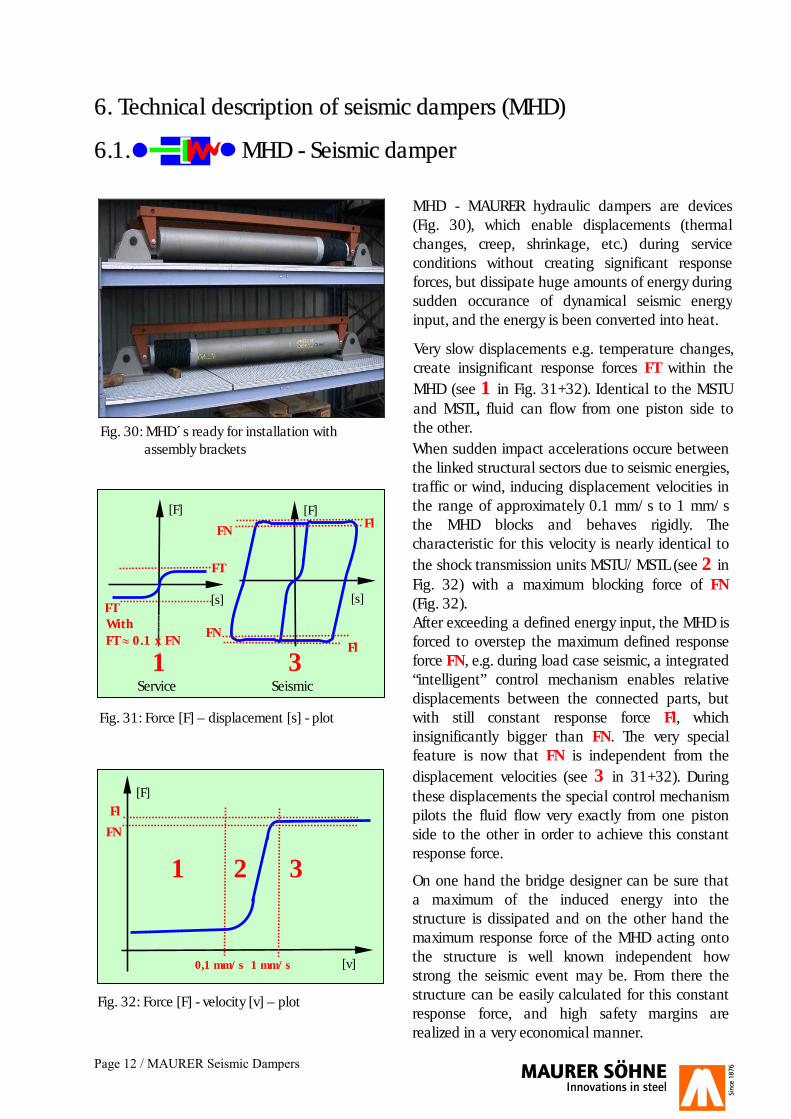
Fig. 30: MHD´s ready for installation with assembly brackets
MHD - MAURER hydraulic dampers are devices (Fig. 30), which enable displacements (thermal changes, creep, shrinkage, etc.) during service conditions without creating significant response forces, but dissipate huge amounts of energy during sudden occurance of dynamical seismic energy input, and the energy is been converted into heat.
Very slow displacements e.g. temperature changes, create insignificant response forces FT within the MHD (see 1 in Fig. 31+32). Identical to the MSTU and MSTL, fluid can flow from one piston side to the other. When sudden impact accelerations occure between the linked structural sectors due to seismic energies, traffic or wind, inducing displacement velocities in the range of approximately 0.1 mm/s to 1 mm/s the MHD blocks and behaves rigidly. The characteristic for this velocity is nearly identical to the shock transmission units MSTU/MSTL (see 2 in Fig. 32) with a maximum blocking force of FN (Fig. 32). After exceeding a defined energy input, the MHD is forced to overstep the maximum defined response force FN, e.g. during load case seismic, a integrated “intelligent” control mechanism enables relative displacements between the connected parts, but with still constant response force Fl, which insignificantly bigger than FN. The very special feature is now that FN is independent from thedisplacement velocities (see 3 in 31+32). During these displacements the special control mechanism pilots the fluid flow very exactly from one piston side to the other in order to achieve this constant response force.
On one hand the bridge designer can be sure that a maximum of the induced energy into the structure is dissipated and on the other hand the maximum response force of the MHD acting onto the structure is well known independent how strong the seismic event may be. From there the structure can be easily calculated for this constant response force, and high safety margins are realized in a very economical manner.
Fig. 32: Force [F] - velocity [v] – plot
Fig. 31: Force [F] – displacement [s] - plot
Service Seismic
[F]
[s]
[F]
[s]
Fl
Fl
1 3
[F]
[v]0,1 mm/s
Fl
1 mm/s
1 2 3
FT
FT
FN
FN
FN With FT � 0.1 x FN

Page 13 / MAURER Seismic Dampers
F C v� ��
F = MHD response force C = Constant value v = displacement velocities up to 1.4 m/s � = damping exponent < 0.02 (2%)
=> due to the low a value the MHD response force is independly acting from the displacement velocity as the term “v�” runs against “1”
Fig. 35: MHD response force equation
Fig. 33: Twin Viaduct Locica in Slovenia with MHDs
Fig. 34: Comparison of equivalent damping coefficients � of different structures and components
Equivalent damping coefficients �:
�� Steel bridge �= 0.02 �� Concrete bridge �= 0.05 �� Elastomeric bearings �= 0.05 to 0.06 �� High damping rubber bearings �= 0.16
to 0.19 �� Lead rubber bearings and friction
pendulum �= 0.30 to 0.40 �� MAURER seismic damper
MHD �= up to 0.61
The damping coefficient � relates to the efficiency � according to following equation:
��
�2
�
This ends up in an maximum efficiency �= 96% for the MHD!
Characteristics of a MHD: �� During service conditions the device is not pre-
tensioned and the fluid is under insignificant pressure.
�� Maximum response force is well defined to a certain limit. No structural damages occur even in case the earthquake was more severe than expected, and the design engineer can easily calculate with this constant maximum response force – independent from velocity –but still be sure to gain the maximum possible structural safety factor. This constant responseforce is resulting from the extra low damping exponent �< 0.02 (Fig. 35).
�� Extreme great efficiency of up to � = 96% which corresponds with a maximum equivalent damping coefficient of 0.61.
�� Maximum response force is given by the MHD with tenths of a second, so structural displacements are minimized.
�� For traffic loads due to braking and acceleration, the MHD acts like a shock transmission unit.
�� Automatic volume compensation of the fluid caused by temperature changes without pressure increase inside the devices. Any compensation containers are located inside. On request they can also be placed outside.
�� No maintenance works necessary. Visual inspection is recommended during the periodic bridge inspections or after an earthquake respectively.
�� The devices are not prone to leaking as special high strength hydraulic sealing rings are used like for caterpillars, for automobile industry and similar machineries. On request prove tests can be carried out.
�� Very little elasticity of 2-5% depending on request.
�� Range of operating temperature: -40°C to 70°C.
�� Small dimensions and simple installation. �� Depending on request spherical hinges are
installed at both device ends to accommodate installation tolerances.
Page 14 / MAURER Seismic Dampers
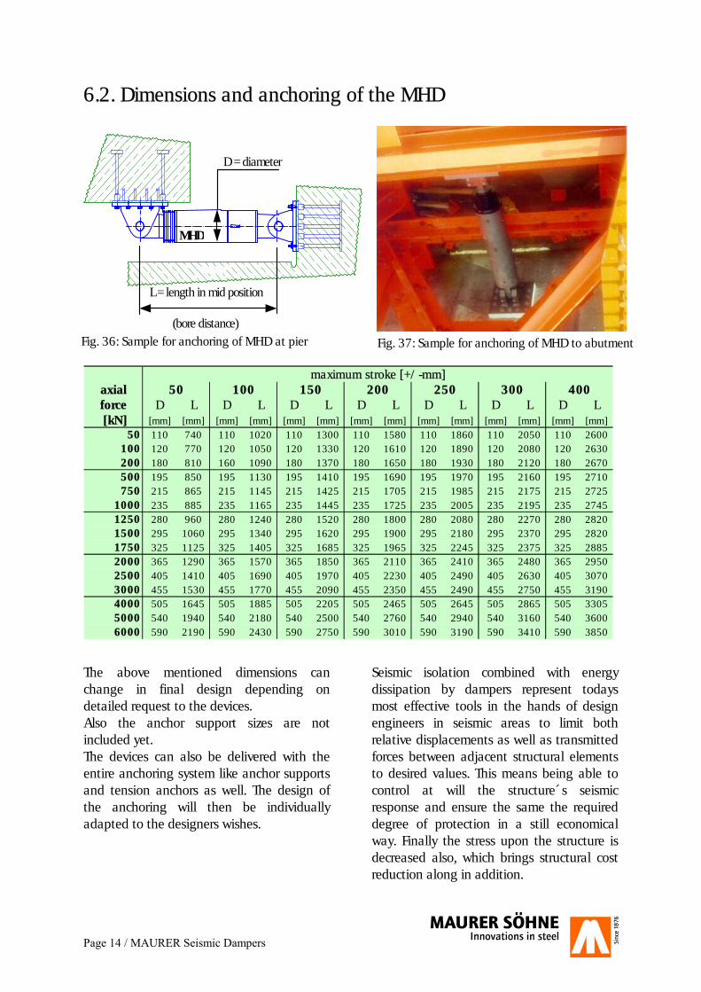
6.2. Dimensions and anchoring of the MHD
L = length in mid position (bore distance)
D = diameter
MHD
maximum stroke [+/-mm]axial 50 100 150 200 250 300 400force D L D L D L D L D L D L D L [kN] [mm] [mm] [mm] [mm] [mm] [mm] [mm] [mm] [mm] [mm] [mm] [mm] [mm] [mm]
50 110 740 110 1020 110 1300 110 1580 110 1860 110 2050 110 2600100 120 770 120 1050 120 1330 120 1610 120 1890 120 2080 120 2630200 180 810 160 1090 180 1370 180 1650 180 1930 180 2120 180 2670500 195 850 195 1130 195 1410 195 1690 195 1970 195 2160 195 2710750 215 865 215 1145 215 1425 215 1705 215 1985 215 2175 215 2725
1000 235 885 235 1165 235 1445 235 1725 235 2005 235 2195 235 27451250 280 960 280 1240 280 1520 280 1800 280 2080 280 2270 280 28201500 295 1060 295 1340 295 1620 295 1900 295 2180 295 2370 295 28201750 325 1125 325 1405 325 1685 325 1965 325 2245 325 2375 325 28852000 365 1290 365 1570 365 1850 365 2110 365 2410 365 2480 365 29502500 405 1410 405 1690 405 1970 405 2230 405 2490 405 2630 405 30703000 455 1530 455 1770 455 2090 455 2350 455 2490 455 2750 455 31904000 505 1645 505 1885 505 2205 505 2465 505 2645 505 2865 505 33055000 540 1940 540 2180 540 2500 540 2760 540 2940 540 3160 540 36006000 590 2190 590 2430 590 2750 590 3010 590 3190 590 3410 590 3850
The above mentioned dimensions can change in final design depending on detailed request to the devices. Also the anchor support sizes are not included yet. The devices can also be delivered with the entire anchoring system like anchor supports and tension anchors as well. The design of the anchoring will then be individually adapted to the designers wishes.
Seismic isolation combined with energy dissipation by dampers represent todays most effective tools in the hands of design engineers in seismic areas to limit both relative displacements as well as transmitted forces between adjacent structural elements to desired values. This means being able to control at will the structure´s seismic response and ensure the same the required degree of protection in a still economical way. Finally the stress upon the structure is decreased also, which brings structural cost reduction along in addition.
Fig. 37: Sample for anchoring of MHD to abutment Fig. 36: Sample for anchoring of MHD at pier
Page 15 / MAURER Seismic Isolators
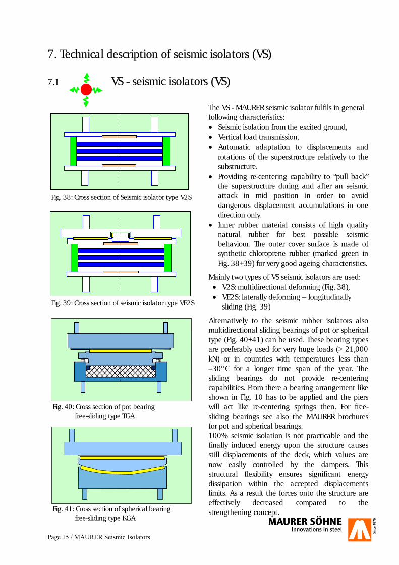
7. Technical description of seismic isolators (VS) 7.1 VS - seismic isolators (VS)
The VS - MAURER seismic isolator fulfils in general following characteristics: �� Seismic isolation from the excited ground, �� Vertical load transmission. �� Automatic adaptation to displacements and
rotations of the superstructure relatively to the substructure.
�� Providing re-centering capability to “pull back” the superstructure during and after an seismic attack in mid position in order to avoid dangerous displacement accumulations in one direction only.
�� Inner rubber material consists of high quality natural rubber for best possible seismic behaviour. The outer cover surface is made ofsynthetic chloroprene rubber (marked green in Fig. 38+39) for very good ageing characteristics.
Mainly two types of VS seismic isolators are used: �� V2S: multidirectional deforming (Fig. 38), �� VE2S: laterally deforming – longitudinally
sliding (Fig. 39)
Alternatively to the seismic rubber isolators also multidirectional sliding bearings of pot or spherical type (Fig. 40+41) can be used. These bearing types are preferably used for very huge loads (> 21,000 kN) or in countries with temperatures less than –30°C for a longer time span of the year. The sliding bearings do not provide re-centering capabilities. From there a bearing arrangement like shown in Fig. 10 has to be applied and the piers will act like re-centering springs then. For free-sliding bearings see also the MAURER brochures for pot and spherical bearings. 100% seismic isolation is not practicable and the finally induced energy upon the structure causes still displacements of the deck, which values are now easily controlled by the dampers. This structural flexibility ensures significant energy dissipation within the accepted displacements limits. As a result the forces onto the structure are effectively decreased compared to the strengthening concept.
Fig. 38: Cross section of Seismic isolator type V2S
Fig. 39: Cross section of seismic isolator type VE2S
Fig. 40: Cross section of pot bearing free-sliding type TGA
Fig. 41: Cross section of spherical bearing free-sliding type KGA
Page 16 / MAURER Seismic Isolators
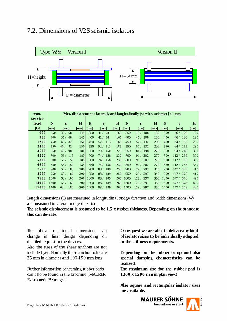
7.2. Dimensions of V2S seismic isolators
Type V2S: Version I Version II
max. Max. displacement s laterally and longitudinally (service/seismic) [+/-mm]service
load D s H D s H D s H D s H [kN] [mm] [mm] [mm] [mm] [mm] [mm] [mm] [mm] [mm] [mm] [mm] [mm]
600 350 35 / 68 145 350 41 / 98 165 350 45 / 108 180 350 46 / 120 190900 400 35 / 68 145 400 41 / 98 165 400 45 / 108 180 400 46 / 120 190
1200 450 40 / 82 150 450 52 / 113 185 450 57 / 132 200 450 64 / 165 2302400 550 40 / 82 150 550 52 / 113 185 550 57 / 132 200 550 64 / 165 2303600 650 46 / 98 180 650 70 / 150 225 650 84 / 198 270 650 94 / 248 3204200 700 53 / 113 185 700 74 / 158 230 700 91 / 202 270 700 112 / 285 3605800 800 53 / 150 185 800 74 / 158 230 800 91 / 202 270 800 112 / 285 3506600 850 53 / 150 185 850 74 / 158 230 850 91 / 202 270 850 112 / 285 3507500 900 63 / 180 200 900 88 / 189 250 900 129 / 297 340 900 147 / 378 4108500 950 63 / 180 200 950 88 / 189 250 950 129 / 297 340 950 147 / 378 4109500 1000 63 / 180 200 1000 88 / 189 260 1000 129 / 297 350 1000 147 / 378 420
14000 1300 63 / 180 200 1300 88 / 189 260 1300 129 / 297 350 1300 147 / 378 42017000 1400 63 / 180 200 1400 88 / 189 260 1400 129 / 297 350 1400 147 / 378 420
Length dimensions (L) are measured in longitudinal bridge direction and width dimensions (W) are measured in lateral bridge direction. The seismic displacement is assumed to be 1.5 x rubber thickness. Depending on the standard this can deviate. The above mentioned dimensions can change in final design depending on detailed request to the devices. Also the sizes of the shear anchors are not included yet. Normally these anchor bolts are 25 mm in diameter and 100-150 mm long. Further information concerning rubber pads can also be found in the brochure „MAURER Elastomeric Bearings“.
On request we are able to deliver any kind of isolator sizes to be individually adapted to the stiffness requirements. Depending on the rubber compound also special damping characteristics can be realized. The maximum size for the rubber pad is 1200 x 1200 mm in plan view! Also square and rectangular isolator sizes are available.
D = diameter D
H =height H – 50mm
Type V2S: Version I Version II
Page 17 / MAURER Seismic Isolators
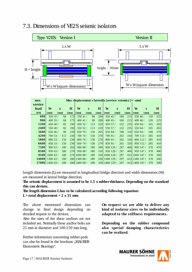
7.3. Dimensions of VE2S seismic isolators
Typ VE2S: Version I Version II
max. Max. displacement s laterally (service/seismic) [+/-mm]service
load W s H W s H W s H W s H [kN] [mm] [mm] [mm] [mm] [mm] [mm] [mm] [mm] [mm] [mm] [mm] [mm]
600 350 35 / 68 175 350 41 / 98 200 350 45 / 108 215 350 46 / 120 225900 400 35 / 68 175 400 41 / 98 200 400 45 / 108 215 400 46 / 120 225
1200 450 40 / 82 190 450 52 / 113 220 450 57 / 132 235 450 64 / 165 2652400 550 40 / 82 190 550 52 / 113 220 550 57 / 132 235 550 64 / 165 2653600 650 46 / 98 220 650 70 / 150 265 650 84 / 198 310 650 94 / 248 3704200 700 53 / 113 230 700 74 / 158 270 700 91 / 202 310 700 112 / 285 4105800 800 53 / 150 230 800 74 / 158 270 800 91 / 202 320 800 112 / 285 4106600 850 53 / 150 230 850 74 / 158 270 850 91 / 202 320 850 112 / 285 4107500 900 63 / 180 260 900 88 / 189 300 900 129 / 297 400 900 147 / 378 4708500 950 63 / 180 270 950 88 / 189 310 950 129 / 297 400 950 147 / 378 4809500 1000 63 / 180 270 1000 88 / 189 330 1000 129 / 297 415 1000 147 / 378 500
14000 1300 63 / 180 280 1300 88 / 189 330 1300 129 / 297 415 1300 147 / 378 50017000 1400 63 / 180 280 1400 88 / 189 330 1400 129 / 297 415 1400 147 / 378 500
Length dimensions (L) are measured in longitudinal bridge direction and width dimensions (W) are measured in lateral bridge direction. The seismic displacement is assumed to be 1.5 x rubber thickness. Depending on the standard this can deviate. The length dimension L has to be calculated according following equation: L + total displacement + 2 x 35 mm The above mentioned dimensions can change in final design depending on detailed request to the devices. Also the sizes of the shear anchors are not included yet. Normally these anchor bolts are 25 mm in diameter and 100-150 mm long. Further information concerning rubber pads can also be found in the brochure „MAURER Elastomeric Bearings“.
On request we are able to deliver any kind of isolator sizes to be individually adapted to the stiffness requirements. Depending on the rubber compound also special damping characteristics can be realized.
W x W (square dimension)
H = height height – 30mm
W x W (square dimension
L x W L x W
Type V2ES: Version I Version II
Page 18 / MAURER Seismic Expansion Joints
8 . Technical information for DS and DS-F seismic swivel-joist expansion joint
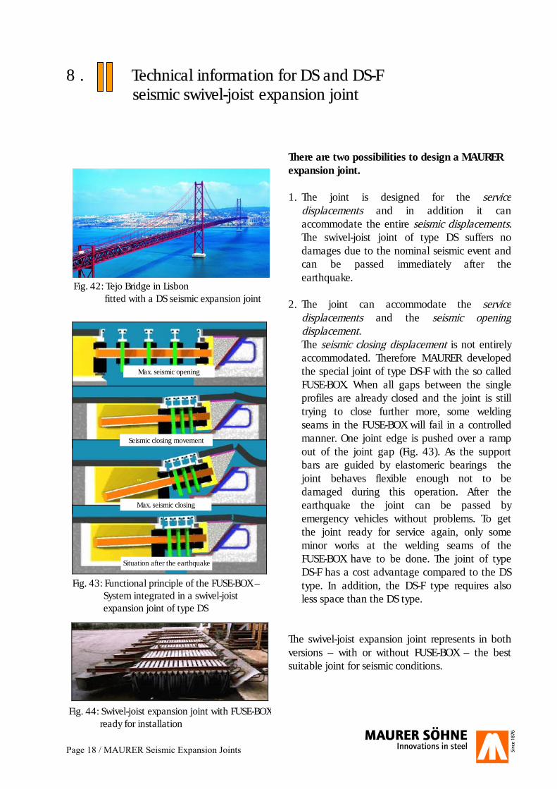
There are two possibilities to design a MAURER expansion joint. 1. The joint is designed for the service
displacements and in addition it can accommodate the entire seismic displacements. The swivel-joist joint of type DS suffers no damages due to the nominal seismic event and can be passed immediately after the earthquake.
2. The joint can accommodate the service
displacements and the seismic opening displacement. The seismic closing displacement is not entirely accommodated. Therefore MAURER developed the special joint of type DS-F with the so called FUSE-BOX. When all gaps between the single profiles are already closed and the joint is still trying to close further more, some welding seams in the FUSE-BOX will fail in a controlled manner. One joint edge is pushed over a ramp out of the joint gap (Fig. 43). As the support bars are guided by elastomeric bearings the joint behaves flexible enough not to be damaged during this operation. After the earthquake the joint can be passed by emergency vehicles without problems. To get the joint ready for service again, only some minor works at the welding seams of the FUSE-BOX have to be done. The joint of type DS-F has a cost advantage compared to the DS type. In addition, the DS-F type requires also less space than the DS type.
The swivel-joist expansion joint represents in both versions – with or without FUSE-BOX – the best suitable joint for seismic conditions.
Fig. 43: Functional principle of the FUSE-BOX – System integrated in a swivel-joist expansion joint of type DS
Max. seismic opening
Max. seismic closing
Situation after the earthquake
Seismic closing movement
Fig. 44: Swivel-joist expansion joint with FUSE-BOX ready for installation
Fig. 42: Tejo Bridge in Lisbon fitted with a DS seismic expansion joint
Page 19 / MAURER Seismic Expansion Joints
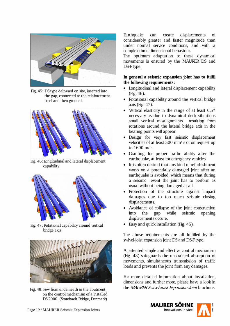
Earthquake can create displacements of considerably greater and faster magnitude than under normal service conditions, and with a complex three dimensional behaviour. The optimum adaptation to these dynamical movements is ensured by the MAURER DS and DS-F type. In general a seismic expansion joint has to fulfil the following requirements: �� Longitudinal and lateral displacement capability
(Fig. 46). �� Rotational capability around the vertical bridge
axis (Fig. 47). �� Vertical elasticity in the range of at least 0,5°
necessary as due to dynamical deck vibrations small vertical misalignments resulting from rotations around the lateral bridge axis in the bearing points will appear.
�� Design for very fast seismic displacement velocities of at least 500 mm/s or on request up to 1600 m/s.
�� Granting for proper traffic ability after the earthquake, at least for emergency vehicles.
�� It is often desired that any kind of refurbishment works on a potentially damaged joint after an earthquake is avoided, which means that during a seismic event the joint has to perform as usual without being damaged at all.
�� Protection of the structure against impact damages due to too much seismic closing displacements.
�� Avoidance of collapse of the joint construction into the gap while seismic opening displacements occure.
�� Easy and quick installation (Fig. 45). The above requirements are all fulfilled by the swivel-joist expansion joint DS and DS-F type. A patented simple and effective control mechanism (Fig. 48) safeguards the unstrained absorption of movements, simultaneous transmission of traffic loads and prevents the joint from any damages. For more detailed information about installation, dimensions and further more, please have a look in the MAURER Swivel-Joist Expansion Joint brochure.
Fig. 45: DS type delivered on site, inserted into the gap, connected to the reinforcement
steel and then grouted.
Fig. 48: Few from underneath in the abutment on the control mechanism of a installed DS 2000 (Storebaelt Bridge, Denmark)
Fig. 46: Longitudinal and lateral displacement capability
Fig. 47: Rotational capability around vertical bridge axis
Page 20 / MAURER Non-linear Time History Analysis
9. General information for a non-linear time history analysis
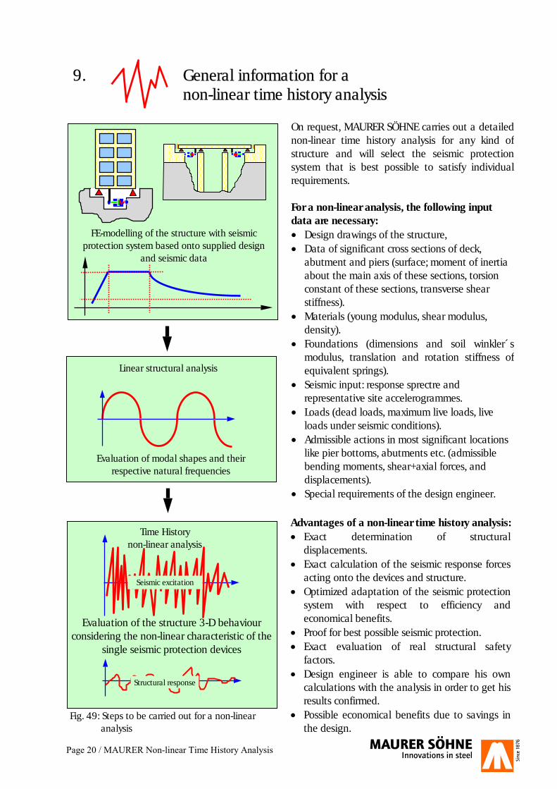
On request, MAURER SÖHNE carries out a detailed non-linear time history analysis for any kind of structure and will select the seismic protection system that is best possible to satisfy individual requirements. For a non-linear analysis, the following input data are necessary: �� Design drawings of the structure, �� Data of significant cross sections of deck,
abutment and piers (surface; moment of inertia about the main axis of these sections, torsion constant of these sections, transverse shear stiffness).
�� Materials (young modulus, shear modulus, density).
�� Foundations (dimensions and soil winkler´s modulus, translation and rotation stiffness of equivalent springs).
�� Seismic input: response sprectre and representative site accelerogrammes.
�� Loads (dead loads, maximum live loads, live loads under seismic conditions).
�� Admissible actions in most significant locations like pier bottoms, abutments etc. (admissible bending moments, shear+axial forces, and displacements).
�� Special requirements of the design engineer.
Advantages of a non-linear time history analysis: �� Exact determination of structural
displacements. �� Exact calculation of the seismic response forces
acting onto the devices and structure. �� Optimized adaptation of the seismic protection
system with respect to efficiency and economical benefits.
�� Proof for best possible seismic protection. �� Exact evaluation of real structural safety
factors. �� Design engineer is able to compare his own
calculations with the analysis in order to get his results confirmed.
�� Possible economical benefits due to savings in the design.
Linear structural analysis
Evaluation of modal shapes and their respective natural frequencies
FE-modelling of the structure with seismic protection system based onto supplied design
and seismic data
Time History non-linear analysis
Evaluation of the structure 3-D behaviour considering the non-linear characteristic of the
single seismic protection devices
Seismic excitation
Structural response
Fig. 49: Steps to be carried out for a non-linear analysis
Page 21 / MAURER Testing of Seismic Protection Devices
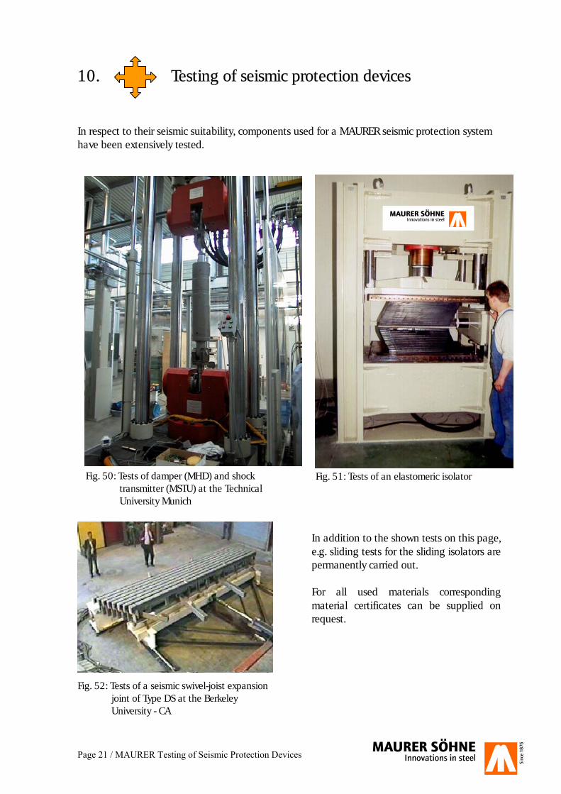
10. Testing of seismic protection devices In respect to their seismic suitability, components used for a MAURER seismic protection system have been extensively tested.
In addition to the shown tests on this page, e.g. sliding tests for the sliding isolators are permanently carried out. For all used materials corresponding material certificates can be supplied on request.
Fig. 50: Tests of damper (MHD) and shock transmitter (MSTU) at the Technical University Munich
Fig. 51: Tests of an elastomeric isolator
Fig. 52: Tests of a seismic swivel-joist expansion joint of Type DS at the Berkeley University - CA