mattive sfr sheet ac1
TRANSCRIPT

scratch
ENTER Project Address: 1330 San Miguel Avenue
Is there a basement or cellar existing or proposed? No
ENTER Proposed TOTAL Net FAR Floor Area (in sq. ft.): 1,456
ENTER Zone ONLY from drop-down list: E-3
ENTER Net Lot Area (in sq. ft.): 5,853
Is the height of existing or proposed buildings 17 feet or greater? Yes
Are existing or proposed buildings two stories or greater? Yes
The FAR Requirements are: REQUIRED**
ENTER Average Slope of Lot: 17.00%
Does the height of existing or proposed buildings exceed 25 feet? No
Is the site in the Hillside Design District? No
Does the project include 500 or more cu. yds. of grading outside the main building footprint? No
FLOOR AREA RATIO (FAR): 0.249
Lot Size Range: 4,000 - 9,999 sq.ft.
MAX FAR Calculation (in sq. ft.): 1,200 + (0.25 x lot size in sq.ft.)
100% MAX FAR: 0.455
100% MAX FAR (in sq. ft.): 2,663
85% of MAX FAR (in sq. ft.): 2,264
80% of MAX FAR (in sq. ft.): 2,131
* NOTE: Percentage total is rounded up.
ENTER Acreage to Convert to square footage: 1.00
Net Lot Area (in sq. ft.): 43560
H:\Group Folders\PLAN\Handouts\Offic ial Handouts\Design Review\FAR_Calculator.x lsx Revised May 26, 2020
Acreage Conversion Calculator
**NOTE: If your project is located on a site with multiple or overlay zones, please contact Planning Staff to confirm whether the FAR limitations are "Required" or "Guideline".
F.A.R. Calculator
The 1456 square foot proposed total is 55% of the MAX FAR.*
Instructions: Enter the information in the white boxes below. The spreadsheet will calculate the proposed FAR (floor area ratio), the 100% max FAR (per the Zoning Ordinance for "Required FAR"), and the 85% max FAR (per the Zoning Ordinance for "Required FAR"). Additionally it will determine whether a FAR Modification is required. "Guideline FAR" calculations are as outlined in the "Applicability" section of the Single Family Residence Design Guidelines, page 23-C.
The Net Lot Area does not include any Public Road Easements or Public Road Right-of-Way areas. The proposed TOTAL Net FAR Floor Area shall include the net floor area of all stories of all building, but may or may not include basement/cellar floor area. For further clarification on these definitions please refer to SBMC §28.15.083 & 30.300. This form has not yet been updated for current Title 30 zone designations, see SBMC §30.05.010 for comparison.
An FAR MOD is not required per SBMC §28.15 or §30.20.030
paper
SHEET INDEX
VICINITY MAPABBREVIATIONS
SITE & ROOF PLAN
detail
SITE & ROOF PLAN
border
THES
E DR
AWIN
GS
DO N
OT
CONT
AIN
THE
NECE
SSAR
Y CO
MPO
NENT
S FO
R CO
NSTR
UCTI
ON
SAFE
TY
sheet no.
date:
plot date:
job no.
scale:
REVISION
Patr
ick
Ma
rr, A
IA, P
E e
xpre
ssly
rese
rve
s hi
s c
om
mo
n la
w c
op
yrig
ht fo
r the
se p
lans
. Th
ese
pla
ns a
re n
ot t
o b
e c
hang
ed
or c
op
ied
in a
ny fo
rm o
r ma
nne
r, no
r are
the
y to
b
e a
ssig
ned
to a
third
pa
rty,
with
out
firs
t ob
tain
ing
the
writ
ten
pe
rmiss
ion
and
co
nse
nt
of P
atr
ick
Ma
rr, A
IA, P
E
★★
PATR
ICK
J. M
AR
R
C24
488
R
ENEW
AL
2/28
/21
LIC
ENSE
DA
RCH
ITEC
T
STATEOF
CA
LIFO
RNIA
patr
ick
mar
r, ai
a pe
arc
hite
ctur
e +
stru
ctur
al d
esig
n21
05 g
illesp
ie s
treet
, san
ta b
arba
ra, c
a 9
3101
805.
898.
2096
// p
atric
k@pa
trick
mar
raia
.com
hatch/fill
4' wood fence
6' w
oo
d fe
nce
6' w
oo
d fe
nce
up
18" garden wall
retainint wall, varies from 0" to 42"
up
18
" ga
rde
n w
all
48
" ga
rde
n w
all
48" garden wall
up
(e) patio, typ
(e) turf
(e) planter area
(e) planter area
(e) planter area
millwork
(e) elec meter
(e) gas meter
(e) water mete
4' (e) sidewalk
(e) conc walk (e) ac driveway
3:12
(e) pitch typ(e
) hip
(e) v
alley
8' parkway
6' setback
6' s
etb
ac
k
6' setb
ac
k
20' setback
nearest uphill manhole, approximate elevation 132.3
approx. fin floor133.5
8.5' x 17.5'
parking space
(approved parking
per BLD2020-02475)
8.5' x 17.5'
parking space
1,259 sf
open yard
20'
20'
doorswall
dimension
6.7'
12'
15.3'
11.7'
6'
34.7'
30'
7.7'
10'
10' typ
Sit
e &
Roof
Pla
n
C-1 of sheets
text ABBREVIATIONS:
a awningab anchor boltabv above(abwp) as-built without permitac asphaltic concreteac air conditioningadj adjacental aluminumalt alternateapp approvedav audio visual
b bottombel belowbldg buildingblk blockblk'g blockingbm beambn boundary nailbn bullnosebot bottombp bi-pass
c casement, coursescab't cabinetcalc's calculationscb catch basincbc california building codecer ceramiccfm cubic feet per minuteclg ceilingcj ceiling joist, control joint,
construction jointcl center line, chain link,
centerlineclos closetclr clearcmu concrete masonry unitco clean outcol columnconc concretecont continuousct ceramic tilectr centercu cubiccw cold water
db decibeldbl doubledemo demolitiondet detaildf douglas firdf drinking fountaindia diameterdim dimensiondisp dispenserdisp disposerdh double hungdj deck joistdr doords down spoutdwgs drawings
e electrical(e) existingea each, exhaust airej expansion jointel elevationelev elevationen edge nailengr engineer(ing)eq equales each sideewwm electric welded wire meshexp exposedext exterior
f frenchfd floor drainfdn foundationff finished floorfg fixed glassfg finish gradefg fuel gasfin finishfj floor joistfl flush, flow lineflash'g flashingflr floorfluor fluorescentfn field nail, face nailfo face offohc free of heart centerfold'g foldingfom face of masonryfopl face of plasterfos face of studfosh face of sheathingfow face of wallfs finish surface, finish slab, far sideft feetftao force transfer around openingftg footing
g gasga gaugegalv galvanizedgb gypsum boardgfci ground fault circuit interruptergi galvanized irongls glassglb glued laminated beamgr groupgrd gradegv gate valve
h hopperhb hose bibbhc handicapped, hollow corehd holdownhdg hot dipped galvanizedhdr headerhdwr hardwarehgr hangerhm hollow metalhoriz horizontalhp high pointht heighthw hot water
insul insulationint interiorips interior pipe sizeinfo information
jt jointjst joist
l lanai, landscape, anglelam laminate(d)lg longllv long leg verticallp low pointls lag screwslts lights
m mechanicalmat'l materialmax maximummb machine boltmfr manufacturermi malleable ironmin minimummiw malleable iron washermo masonry opening
n north(n) newnat naturalng natural gradenic not in contractno numberns near sidents not to scale
oc on centerocc occupancyopn'g openingopp oppositeo/ over
p panel, patio, plumbing(p) proposedpa planter areapart'n partitionpcc portland cement concretepkt pocketpl property linepl plateplant'g plantingplas plasterplwd plywoodpoc point of connectionpr pairpt pressure treatedpvc polyvinyl chloride
q quad
r radius, rolling(r) replacer/s resawn texturera return airraft rafterrd roof drainref refer, reference, refrigeratorreq'd requiredresil resilientrm roomro rough openingros rough sawn texturerr roof rafterrw redwood
s sewer, structurals & p shelf and poles4s surfaced four sidessa supply airsc scale, solid corescl solid composite lumbersd storm drainsec sectionsf square feetsg safety glazingsh single hungsht sheetsht'g sheathingshwr showersi square inchessid'g sidingsim similarsl slidingsld'g slidingslop'g slopingslts sidelightssn sill nailspecs specificationssq ft square feetss select structural, stainless steelstd standardstf steel trowel finishstl steelsw shear wallsws shear wall segmentsym symmetrical
t toilet, topt & b top and bottomt & g tongue and groovetel telephonetg top of gratethk thick(ness)tow top of walltp top of pavementtos top of steelto sht'g top of sheathingts tube steeltv televisiontyp typical
uno unless noted otherwise
v ventvtr vent through roofvert verticalvest vestibule
w wastew/ withw/o withoutwd woodwdw windowwi wrought ironwp water proofwr water resistantws water supply, wood screwswt water tight, weight
ProjectLocation
6/3/21
(e) 120 sf shed
(e) primary residence
(hatched)
(e) Accessory Dwelling Unit
(under construction)
(e) ridge
(e)
ridg
e
(e) h
ip
(e) v
alley
(e) h
ip
(e) hip
(e) h
ip
(e) hip
(e)
ridg
e
(e) h
ip
(e) hip
52.34'
n 83° 60' e
103.
68'
n 05
° 14
' 20"
w
103.29'
n 09° 44' 20" w
60.48'
centerline
San Miguel Avenue
(e) covered porch
(e) concrete stairs
(e) concrete stairs
north
Scale: 1/8" = 1'-0"
(e) comp shingle roof
PROJECT DESCRIPTION:• replace all exterior doors and windows at primary residence• add two new windows at accessory dwelling unit (within existing non-
conforming front setback)• construct new 144 sf elevated deck serving primary residence• 340 sf interior remodel
(Note that the accessory dwelling unit has been approved under BLD2020-02475, and conditions approved under that permit are shown as “existing” in these plans.)
OWNERS: Nilus & Disha Mattive1330 San Miguel AvenueSanta Barbara, CA 93109(805)
DESIGN & STRUCTURAL ENGINEERING:Patrick Marr, AIA, PE2105 Gillespie StreetSanta Barbara, CA 93101(805) 898-2096
GOVERNING CODES:2019 California Building Code (structural provisions)2019 California Residential Code2019 California Plumbing Code2019 California Mechanical Code2019 California Electric Code2019 California Energy Code2019 California Green Building Code
ASSESSOR'S PARCEL:045-042-014
ZONING DATA:Parcel Data:• Parcel Address: 1330 San Miguel Avenue, Santa Barbara, CA 93109• Zone: Zone: E-3/SD-3 (SBMC Title 28)• Coastal Zone Jurisdiction: Non-Appealable Jurisdiction
(Coastal Exemption granted 9/29/2020, PLN2020-00464)• Hillside Design District: No • Parcel Slope: 21%, per City records• High Fire Hazard Area: No • FEMA Flood Zone: X
Lot Area: 5,853 sfgross net
Existing Floor Area:Existing Primary Residence Living Area: 1,061. sf 1,002. sfExisting Accessory Dwelling Unit: 495. sf 454. sfExisting Shed: 120. sf 106. sfExisting Building Area: 1,676. sf 1,562. sf
Proposed Elevated Deck: 144. sf
Existing Crawlspace: 934. sf 873. sf(existing crawlspace is unfinished and is not considered floor area)
Net Floor Area Include in FAR:1,002 (primary residence) + 106 (shed) = 1,108. sf
Area of Interior Remodel: 338. sf
YEAR OF ORIGINAL CONSTRUCTION:1953
OCCUPANCY:R-3/U
FIRE SPRINKLERS:yes
CONSTRUCTION:Type V-B (unlimited allowable area)
CUT AND FILL:Cut: 2 cu. yards (deck footing excavations)Fill: 0 cu. yards
STORM WATER MANAGEMENT PLAN:New impermeable surfaces: 0 sf (proposed deck has spaced decking and will drain to existing grade below)
MATERIALS & FINISHES:Roofing: (e) charcoal composition shingleStucco: fine sand finish, whiteFascia: painted, light grayWindows: clear anodized aluminumDecking: tropical hardwoodGuardrail: stainless steel cabling with black fascia mounted posts & tropical
hardwood cap
(e) hip
portion of (e) ADU below primary residence (under construction)
(e) ADU (under construction)
(e) stairs (under construction)
remodel of the Mattive Residence 1330 San Miguel Avenue
Santa Barbara, CA 93109
(e) planter areaproposed
elevated deck (spaced decking)
(e) ADU condensing unit (under construction)
SHEET INDEX:
C-1 Site & Roof Plan
A-1 Accessory Dwelling Unit Demolition & Floor PlansA-2 Upper Floor (Primary Residence) Existing Floor PlanA-3 Proposed Exterior ElevationsA-4 Proposed Exterior Elevations & Building Section
PARKING:Existing Parking - Primary Residence:
0 covered / 1 uncovered parking space Existing Parking – Accessory Dwelling Unit:
0 covered / 0 uncovered parking spaces (Pursuant to Government Code 65852.2 (post January 1, 2020) based on proximity to public transit)
GENERAL NOTES:1. All landscaping is to remain, protect in place, uno.2. The building as designed meets or exceeds Title 24 energy
conservation measures.3. All egress windows shall conform to CRC R310.2 and shall have net
clear openable area of 5.7 square feet. The net minimum clear openable height dimension shall be 24 inches. The net minimum clear openable width dimension shall be 20 inches. Finished sill height shall be not more than 44 inches. Windows shall be openable from inside without keys, tools, or special knowledge. Window dimensions shown on schedule shall be coordinated with the particular manufacturer’s sizes to assure conformance.
4. Provide 24" minimum clear in font of toilet in a 30" minimum wide compartment.
5. Provide 1,024 square inch minimum shower compartment, containing 30" minimum diameter.
6. Wall coverings in showers and tubs shall be tile, or equal, to 72" above the drain. Enclosures shall be of approved safety glazing and shower doors shall swing out. Windows in showers shall be safety glazed when sill is within 60" above the drain.
7. Provide hardwired smoke detectors (SD) with a battery backup. (In existing portions of building beyond are of alteration, smoke detectors may be battery operated.) Smoke detectors shall be located in rooms and corridors giving direct access to sleeping areas, on ceilings within each sleeping area, on each story of multistory dwellings, and in close proximity to stairs on upper level. Detectors shall sound an alarm audible in all sleeping areas of the dwelling.
8. Provide hardwired carbon monoxide detectors (CO) with a battery backup. (In existing portions of building beyond are of alteration, CO detectors may be battery operated.) CO detectors shall be located outside each separate dwelling unit sleeping area in the immediate vicinity of the bedrooms and on each story of multistory dwellings. Detectors shall sound an alarm audible in all sleeping areas of the dwelling.
9. Fireblock stud walls (at 10 feet on center maximum, horizontal and vertical), enclosed and concealed spaces, and at openings around vents, pipes, ducts and chimneys, between attic and chimney chase, at stair stringers, and similar spaces at ceiling and floor levels.
10. The largest rise or run in stairs shall not exceed the smallest by more than 3/8".
11. All glazing in hazardous locations shall be identified by a permanent label identifying it as safety glazing.
12. Provide low flow toilets (1.28 gpf average), lavatory faucets (1.2 gpm at 60 psi), kitchen faucets (1.8 gpm max. at 60 psi, .8 gpm min. at 20 psi) and shower heads (1.8 gpm at 80 psi). Showers with multiple shower heads shall have shall have a combined flow rate of 1.8 gpm at 80 psi.
13. Provide 12” square permanently accessible bathtub access panel or use a non-slip joint trap.
14. Shower/tub combo shall have pressure balance or thermostatic mixing valve.
15. All doors and windows shall be dual glazed, with U = .54 max, SHGC = .34 max. New skylights shall be dual glazed with U = .45 max, SHGC = .25 max. Refer to Sheet T-24.
16. Typical insulation:Roof - R-30Exterior Walls - R-13Floor above Accessory Dwelling Unit - R-30
At vaulted ceilings and floor, spray-foam isolation shall be Iceynene MC-D-200, installed per ICC ESR-3199, R = 6.6 per inch. Provide stripping or furring as required to provide adequate depth for required insulation value.
17. Strap water heater at top and bottom with 1 1/2" x 16 ga. steel strap with 3/8" Ø x 3" lag screw at each end to stud.
18. Provide anti-siphon device at hose bibbs.19. Interior wall finish shall be gypsum wallboard. Verify finished surface
and color with owner.20. Install 2 layers Grade D paper between plywood sheathing and
exterior stucco lath.21. All stucco shall be 7/8" portland cement plaster with paper backed
lath with 16 gauge staples at 6" oc.22. Remodeling pre-1978 structures without using Lead Safe Work Practices
is a violation of the California Code of Regulations Section 105256. Contractors, remodelers and painters are shall use "lead-safe" work practices pursuant to Title 17, California Code of Regulations Section 36050. Construction debris known to contain lead-based paint must be disposed at an approved location.
(refer to sheet A-4 for Door & Window Notes)
nearest fire hydrant approx.
75' away
temporary construction equipment/
concrete wash-out area
required cone of vision at driveway,
no plants, shrubs or walls exceeding 42"
tall in this hatched area
(e) raised container vegetable garden
(barrier between parking & Accessory Dweilling Unit, under
construction)
ENTER Project Address: 1330 San Miguel Avenue
Is there a basement or cellar existing or proposed? No
ENTER Proposed TOTAL Net FAR Floor Area (in sq. ft.): 1,108
ENTER Zone ONLY from drop-down list: E-3
ENTER Net Lot Area (in sq. ft.): 5,853
Is the height of existing or proposed buildings 17 feet or greater? Yes
Are existing or proposed buildings two stories or greater? Yes
The FAR Requirements are: REQUIRED**
ENTER Average Slope of Lot: 21.00%
Does the height of existing or proposed buildings exceed 25 feet? No
Is the site in the Hillside Design District? No
Does the project include 500 or more cu. yds. of grading outside the main building footprint? No
FLOOR AREA RATIO (FAR): 0.189
Lot Size Range: 4,000 - 9,999 sq.ft.
MAX FAR Calculation (in sq. ft.): 1,200 + (0.25 x lot size in sq.ft.)
100% MAX FAR: 0.455
100% MAX FAR (in sq. ft.): 2,663
85% of MAX FAR (in sq. ft.): 2,264
80% of MAX FAR (in sq. ft.): 2,131
* NOTE: Percentage total is rounded up.
ENTER Acreage to Convert to square footage: 1.00
Net Lot Area (in sq. ft.): 43560
H:\Group Folders\PLAN\Handouts\Offic ial Handouts\Design Review\FAR_Calculator.x lsx Revised May 26, 2020
Acreage Conversion Calculator
**NOTE: If your project is located on a site with multiple or overlay zones, please contact Planning Staff to confirm whether the FAR limitations are "Required" or "Guideline".
F.A.R. Calculator
The 1108 square foot proposed total is 42% of the MAX FAR.*
Instructions: Enter the information in the white boxes below. The spreadsheet will calculate the proposed FAR (floor area ratio), the 100% max FAR (per the Zoning Ordinance for "Required FAR"), and the 85% max FAR (per the Zoning Ordinance for "Required FAR"). Additionally it will determine whether a FAR Modification is required. "Guideline FAR" calculations are as outlined in the "Applicability" section of the Single Family Residence Design Guidelines, page 23-C.
The Net Lot Area does not include any Public Road Easements or Public Road Right-of-Way areas. The proposed TOTAL Net FAR Floor Area shall include the net floor area of all stories of all building, but may or may not include basement/cellar floor area. For further clarification on these definitions please refer to SBMC §28.15.083 & 30.300. This form has not yet been updated for current Title 30 zone designations, see SBMC §30.05.010 for comparison.
An FAR MOD is not required per SBMC §28.15 or §30.20.030
rem
odel of
the
Matt
ive R
esid
ence
133
0 S
an M
iguel A
venue
Santa
Barb
ara
, C
A 9
31
09
6/3/21
scratchpaper
detail
22
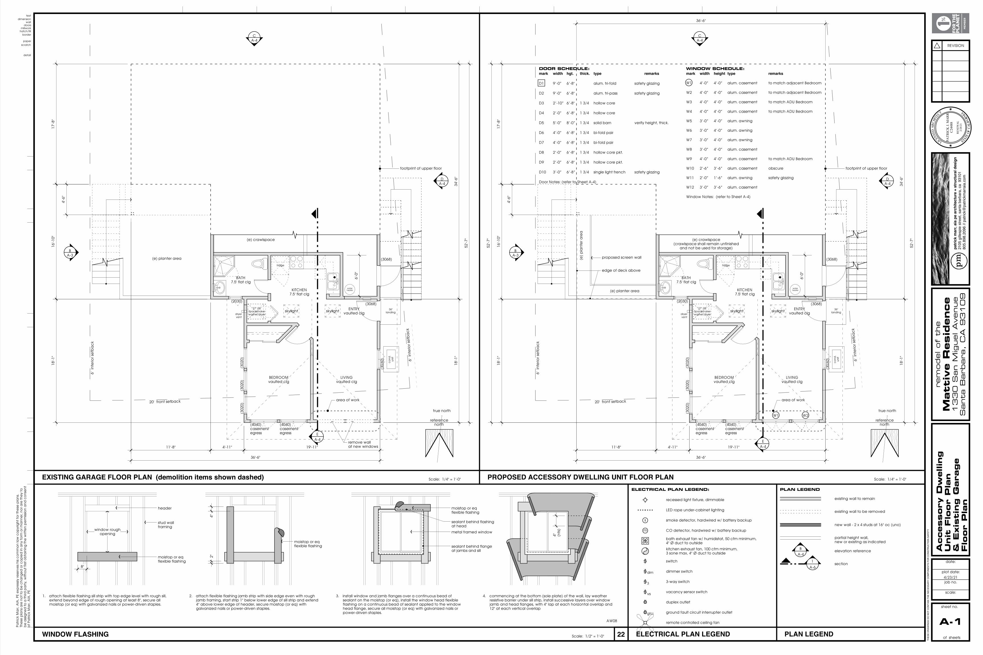
EXISTING GARAGE FLOOR PLAN (demolition items shown dashed) Scale: 1/4" = 1'-0" Scale: 1/4" = 1'-0"PROPOSED ACCESSORY DWELLING UNIT FLOOR PLAN
ELECTRICAL PLAN LEGEND PLAN LEGEND
border
THES
E DR
AWIN
GS
DO N
OT
CONT
AIN
THE
NECE
SSAR
Y CO
MPO
NENT
S FO
R CO
NSTR
UCTI
ON
SAFE
TY
sheet no.
date:
plot date:
job no.
scale:
REVISION
Patr
ick
Ma
rr, A
IA, P
E e
xpre
ssly
rese
rve
s hi
s c
om
mo
n la
w c
op
yrig
ht fo
r the
se p
lans
. Th
ese
pla
ns a
re n
ot t
o b
e c
hang
ed
or c
op
ied
in a
ny fo
rm o
r ma
nne
r, no
r are
the
y to
b
e a
ssig
ned
to a
third
pa
rty,
with
out
firs
t ob
tain
ing
the
writ
ten
pe
rmiss
ion
and
co
nse
nt
of P
atr
ick
Ma
rr, A
IA, P
E
★★
PATR
ICK
J. M
AR
R
C24
488
R
ENEW
AL
2/28
/21
LIC
ENSE
DA
RCH
ITEC
T
STATEOF
CA
LIFO
RNIA
patr
ick
mar
r, ai
a pe
arc
hite
ctur
e +
stru
ctur
al d
esig
n21
05 g
illesp
ie s
treet
, san
ta b
arba
ra, c
a 9
3101
805.
898.
2096
// p
atric
k@pa
trick
mar
raia
.com
hatch/fill
20' front setback
6'
int
erio
r se
tba
ck
6' i
nte
rior s
etb
ac
k
20' front setback
6'
int
erio
r se
tba
ck
6' i
nte
rior s
etb
ac
k
fridge
27" GE Spacemaker washer/dryerdryer
vent
36" landing
co
nd.
unit
water heater(e) planter area
(e)
pla
nte
r are
a
fridge
27" GE Spacemaker washer/dryerdryer
vent
36" landing
co
nd.
unit
water heater
(e) planter area
millwork
(3068)
(3068)
(2030)
(302
0)
(303
0)
(4040) casement egress
(302
0)(3
020)
(4040) casement egress
(3068)
(3068)
(2030)
(302
0)
(303
0)
(4040) casement egress
(302
0)(3
020)
(4040) casement egress
doors
BA-3
CA-4
DA-4
skylightskylight
BA-3
CA-4
DA-4
skylightskylight
wall
8"
4"2"
window rough opening
Scale: 1/2" = 1'-0"WINDOW FLASHING
moistop or eq flexible flashing
AW08
1. attach flexible flashing sill strip with top edge level with rough sill, extend beyond edge of rough opening at least 8", secure all moistop (or eq) with galvanized nails or power-driven staples.
2. attach flexible flashing jamb strip with side edge even with rough jamb framing, start strip 1" below lower edge of sill strip and extend 4" above lower edge of header, secure moistop (or eq) with galvanized nails or power-driven staples.
3. install window and jamb flanges over a continuous bead of sealant on the moistop (or eq), install the window head flexible flashing on a continuous bead of sealant applied to the window head flange, secure all moistop (or eq) with galvanized nails or power-driven staples.
4. commencing at the bottom (sole plate) of the wall, lay weather resistive barrier under sill strip, install successive layers over window jamb and head flanges, with 4" lap at each horizontal overlap and 12" at each vertical overlap
header moistop or eq flexible flashing
stud wall framing
metal framed window
moistop or eq flexible flashing
sealant behind flange at jambs and sill
sealant behind flashing at head
4" (nts
)
dimension
52'-7
"
34'-6
"18
'-1"
36'-6"
17'-8
"16
'-10"
18'-1
"
36'-6"
4'-6
"
19'-11"4'-11"11'-8"
6'-0
"
52'-7
"
52'-7
"
34'-6
"18
'-1"
17'-8
"16
'-10"
18'-1
"
36'-6"
4'-6
"
19'-11"4'-11"11'-8"
6'-0
"
DOOR SCHEDULE:mark width hgt. thick. type remarks
D1 9’-0” 6’-8" alum. tri-fold safety glazing
D2 9’-0” 6’-8" alum. tri-pass safety glazing
D3 2’-10” 6’-8" 1 3/4 hollow core
D4 2’-0” 6’-8" 1 3/4 hollow core
D5 5’-0” 8’-0” 1 3/4 solid barn verify height, thick.
D6 4’-0” 6’-8" 1 3/4 bi-fold pair
D7 4’-0” 6’-8" 1 3/4 bi-fold pair
D8 2’-0” 6’-8" 1 3/4 hollow core pkt.
D9 2’-0” 6’-8" 1 3/4 hollow core pkt.
D10 3’-0” 6’-8” 1 3/4 single light french safety glazing
Door Notes: (refer to Sheet A-4)
text
A-1 of sheets
Accessory
Dw
elli
ng
Unit
Flo
or
Pla
n
& E
xis
ting G
ara
ge
Flo
or
Pla
n
4/23/21
EA-4
reference north
true north
footprint of upper floor
(e) crawlspace (crawlspace shall remain unfinished
and not be used for storage)
1
A-6
partial height wall, new or existing as indicated
elevation reference
existing wall to be removed
new wall - 2 x 4 studs at 16" oc (uno)
PLAN LEGEND
existing wall to remain
section
BA-4
KITCHEN 7.5' flat clg
BATH 7.5' flat clg
BEDROOM vaulted clg
LIVING vaulted clg
ELECTRICAL PLAN LEGEND:
3
dim
gfci
s smoke detector, hardwired w/ battery backup
bath exhaust fan w/ humidistat, 50 cfm minimum, 4" Ø duct to outside
recessed light fixture, dimmable
switch
dimmer switch
3-way switch
duplex outlet
ground fault circuit interrupter outlet
remote controlled ceiling fan
LED rope under-cabinet lighting
m CO detector, hardwired w/ battery backup
kitchen exhaust fan, 100 cfm minimum, 3 sone max, 4" Ø duct to outside
vs vacancy sensor switch
ENTRY vaulted clg
D1
rem
odel of
the
Matt
ive R
esid
ence
133
0 S
an M
iguel A
venue
Santa
Barb
ara
, C
A 9
31
09
proposed screen wall
edge of deck above
EA-4
reference north
true north
footprint of upper floor
(e) crawlspace
KITCHEN 7.5' flat clg
BATH 7.5' flat clg
BEDROOM vaulted clg
LIVING vaulted clg
ENTRY vaulted clg
remove wall at new windows
W1 W2
area of workarea of work
WINDOW SCHEDULE:mark width height type remarks
W1 4’-0” 4’-0” alum. casement to match adjacent Bedroom
W2 4’-0” 4’-0” alum. casement to match adjacent Bedroom
W3 4’-0” 4’-0” alum. casement to match ADU Bedroom
W4 4’-0” 4’-0” alum. casement to match ADU Bedroom
W5 3’-0” 4’-0” alum. awning
W6 3’-0” 4’-0” alum. awning
W7 3’-0” 4’-0” alum. awning
W8 3’-0” 4’-0” alum. casement
W9 4’-0” 4’-0” alum. casement to match ADU Bedroom
W10 2’-6” 3’-6” alum. casement obscure
W11 2’-0” 1’-6” alum. awning safety glazing
W12 3’-0” 3’-6” alum. casement
Window Notes: (refer to Sheet A-4)
W1
scratchpaper
detail
19 20 21 22 23 24
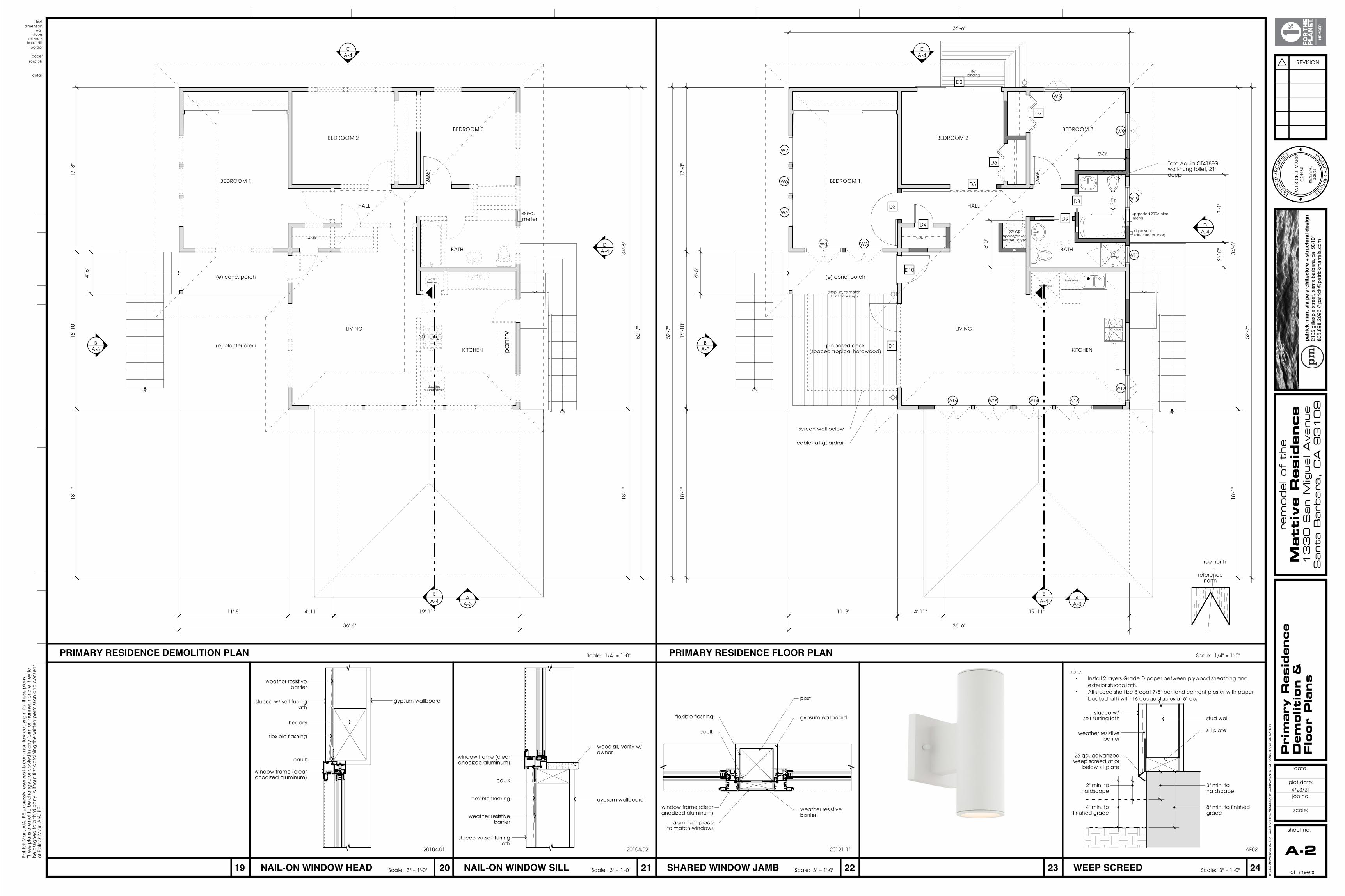
Scale: 1/4" = 1'-0" PRIMARY RESIDENCE FLOOR PLAN Scale: 1/4" = 1'-0"PRIMARY RESIDENCE DEMOLITION PLAN
border
THES
E DR
AWIN
GS
DO N
OT
CONT
AIN
THE
NECE
SSAR
Y CO
MPO
NENT
S FO
R CO
NSTR
UCTI
ON
SAFE
TY
sheet no.
date:
plot date:
job no.
scale:
REVISION
Patr
ick
Ma
rr, A
IA, P
E e
xpre
ssly
rese
rve
s hi
s c
om
mo
n la
w c
op
yrig
ht fo
r the
se p
lans
. Th
ese
pla
ns a
re n
ot t
o b
e c
hang
ed
or c
op
ied
in a
ny fo
rm o
r ma
nne
r, no
r are
the
y to
b
e a
ssig
ned
to a
third
pa
rty,
with
out
firs
t ob
tain
ing
the
writ
ten
pe
rmiss
ion
and
co
nse
nt
of P
atr
ick
Ma
rr, A
IA, P
E
★★
PATR
ICK
J. M
AR
R
C24
488
R
ENEW
AL
2/28
/21
LIC
ENSE
DA
RCH
ITEC
T
STATEOF
CA
LIFO
RNIA
patr
ick
mar
r, ai
a pe
arc
hite
ctur
e +
stru
ctur
al d
esig
n21
05 g
illesp
ie s
treet
, san
ta b
arba
ra, c
a 9
3101
805.
898.
2096
// p
atric
k@pa
trick
mar
raia
.com
hatch/fill
up
up
elec. meter
up
up
millwork
24" c
lr.
req
'd
27" GE Spacemaker washer/dryer
refrigerator
30" range
dishwasher
32" shower
36" landing
dryer vent (duct under floor)
(step up, to match front door step)
Toto Aquia CT418FG wall-hung toilet, 21" deep
upgraded 200A elec. meter
(266
8)
(266
8)
doors
W3W4
W5
W6
W7
W8
W9
W10
W12
W13W14W15W16
D1
D2
D3
D4
D5
D6
D7
D8
D9
W11
D10
water heater
30" range
stacking washer/dryer
pa
ntry
wall
WEEP SCREED Scale: 3" = 1'-0"
AF02
stucco w/ self-furring lath
26 ga. galvanized weep screed at or
below sill plate
3" min. to hardscape
8" min. to finished grade
weather resistive barrier
2" min. to hardscape
4" min. to finished grade
sill plate
stud wall
note:• Install 2 layers Grade D paper between plywood sheathing and
exterior stucco lath.• All stucco shall be 3-coat 7/8" portland cement plaster with paper
backed lath with 16 gauge staples at 6" oc.
NAIL-ON WINDOW SILL Scale: 3" = 1'-0"
20104.02
window frame (clear anodized aluminum)
caulk
flexible flashing
weather resistive barrier
stucco w/ self furring lath
gypsum wallboard
wood sill, verify w/ owner
NAIL-ON WINDOW HEAD Scale: 3" = 1'-0"
20104.01
weather resistive barrier
stucco w/ self furring lath
gypsum wallboard
header
flexible flashing
caulk
window frame (clear anodized aluminum)
SHARED WINDOW JAMB Scale: 3" = 1'-0"
20121.11
gypsum wallboard
weather resistive barrier
post
flexible flashing
caulk
window frame (clear anodized aluminum)
aluminum piece to match windows
dimension
52'-7
"
34'-6
"18
'-1"
36'-6"
52'-7
"
17'-8
"16
'-10"
18'-1
"
36'-6"
4'-6
"
19'-11"4'-11"11'-8"
52'-7
"
34'-6
"18
'-1"
17'-8
"16
'-10"
18'-1
"
36'-6"
4'-6
"
19'-11"4'-11"11'-8"
2'-1
0"7'
-1"
5'-0"
5'-0
"
text
A-2 of sheets
4/23/21
reference north
true north
BEDROOM 1
BEDROOM 2
BEDROOM 3
HALL
BATH
KITCHEN
LIVING
coats
proposed deck (spaced tropical hardwood)
(e) conc. porch
BEDROOM 1
BEDROOM 2
BEDROOM 3
HALL
BATH
KITCHEN
LIVING
coats
(e) planter area
(e) conc. porch
Pri
mary
Resid
ence
Dem
olit
ion &
Flo
or
Pla
ns
CA-4
DA-4
AA-3
BA-3
CA-4
DA-4
AA-3
BA-3
EA-4
EA-4
rem
odel of
the
Matt
ive R
esid
ence
133
0 S
an M
iguel A
venue
Santa
Barb
ara
, C
A 9
31
09
screen wall below
cable-rail guardrail
scratchpaper
A
B
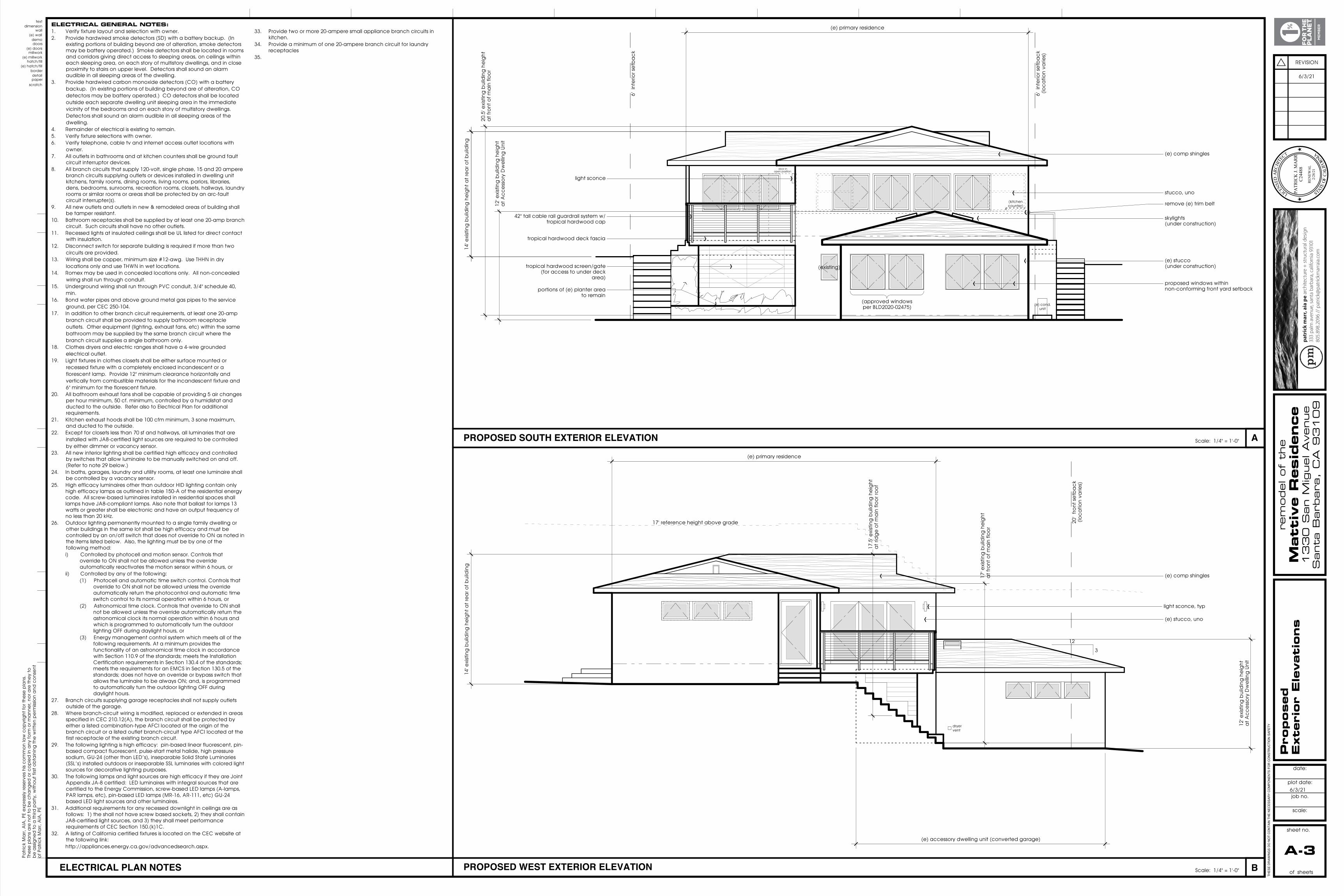
PROPOSED SOUTH EXTERIOR ELEVATION Scale: 1/4" = 1'-0"
Scale: 1/4" = 1'-0"
detail
PROPOSED WEST EXTERIOR ELEVATION ELECTRICAL PLAN NOTES
THES
E DR
AWIN
GS
DO N
OT
CONT
AIN
THE
NECE
SSAR
Y CO
MPO
NENT
S FO
R CO
NSTR
UCTI
ON
SAFE
TY
sheet no.
date:
plot date:
job no.
scale:
REVISION
Patr
ick
Ma
rr, A
IA, P
E e
xpre
ssly
rese
rve
s hi
s c
om
mo
n la
w c
op
yrig
ht fo
r the
se p
lans
. Th
ese
pla
ns a
re n
ot t
o b
e c
hang
ed
or c
op
ied
in a
ny fo
rm o
r ma
nne
r, no
r are
the
y to
b
e a
ssig
ned
to a
third
pa
rty,
with
out
firs
t ob
tain
ing
the
writ
ten
pe
rmiss
ion
and
co
nse
nt
of P
atr
ick
Ma
rr, A
IA, P
E
★★
PATR
ICK
J. M
AR
R
C24
488
R
ENEW
AL
2/28
/21
LIC
ENSE
DA
RCH
ITEC
T
STATEOF
CA
LIFO
RNIA
border(e) hatch/fill
hatch/fill(e) millwork
6'
int
erio
r se
tba
ck
6'
int
erio
r se
tba
ck
(loc
atio
n va
ries)
20
' fro
nt s
etb
ac
k (lo
ca
tion
varie
s)
millwork
dryer vent
(e) cond. unit
(e) doors
(existing)
(approved windows per BLD2020-02475)
doors
3
12
demo(e) wall
17' reference height above grade
door in open position
(kitchen counter)
wall
12' e
xist
ing
bui
ldin
g h
eig
ht
at A
cc
ess
ory
Dw
ellin
g U
nit
dimension (e) primary residence
(e) primary residence
(e) accessory dwelling unit (converted garage)
14' e
xist
ing
bui
ldin
g h
eig
ht a
t re
ar o
f bui
ldin
g14
' exi
stin
g b
uild
ing
he
ight
at r
ea
r of b
uild
ing
20.5
' exi
stin
g b
uild
ing
he
ight
a
t fro
nt o
f ma
in fl
oo
r
14' e
xist
ing
bui
ldin
g h
eig
ht a
t re
ar o
f bui
ldin
g
12' e
xist
ing
bui
ldin
g h
eig
ht
at A
cc
ess
ory
Dw
ellin
g U
nit
17' e
xist
ing
bui
ldin
g h
eig
ht
at f
ront
of m
ain
flo
or
17.5
' exi
stin
g b
uild
ing
he
ight
a
t rid
ge
of m
ain
flo
or r
oo
f
stucco, uno
text
A-3 of sheets
6/3/21
Pro
posed
Exte
rior
Ele
vati
ons
(e) stucco (under construction)
(e) comp shingles
(e) stucco, uno
(e) comp shingles
ELECTRICAL GENERAL NOTES:1. Verify fixture layout and selection with owner.2. Provide hardwired smoke detectors (SD) with a battery backup. (In
existing portions of building beyond are of alteration, smoke detectors may be battery operated.) Smoke detectors shall be located in rooms and corridors giving direct access to sleeping areas, on ceilings within each sleeping area, on each story of multistory dwellings, and in close proximity to stairs on upper level. Detectors shall sound an alarm audible in all sleeping areas of the dwelling.
3. Provide hardwired carbon monoxide detectors (CO) with a battery backup. (In existing portions of building beyond are of alteration, CO detectors may be battery operated.) CO detectors shall be located outside each separate dwelling unit sleeping area in the immediate vicinity of the bedrooms and on each story of multistory dwellings. Detectors shall sound an alarm audible in all sleeping areas of the dwelling.
4. Remainder of electrical is existing to remain.5. Verify fixture selections with owner.6. Verify telephone, cable tv and internet access outlet locations with
owner.7. All outlets in bathrooms and at kitchen counters shall be ground fault
circuit interruptor devices.8. All branch circuits that supply 120-volt, single phase, 15 and 20 ampere
branch circuits supplying outlets or devices installed in dwelling unit kitchens, family rooms, dining rooms, living rooms, parlors, libraries, dens, bedrooms, sunrooms, recreation rooms, closets, hallways, laundry rooms or similar rooms or areas shall be protected by an arc-fault circuit interrupter(s).
9. All new outlets and outlets in new & remodeled areas of building shall be tamper resistant.
10. Bathroom receptacles shall be supplied by at least one 20-amp branch circuit. Such circuits shall have no other outlets.
11. Recessed lights at insulated ceilings shall be UL listed for direct contact with insulation.
12. Disconnect switch for separate building is required if more than two circuits are provided.
13. Wiring shall be copper, minimum size #12-awg. Use THHN in dry locations only and use THWN in wet locations.
14. Romex may be used in concealed locations only. All non-concealed wiring shall run through conduit.
15. Underground wiring shall run through PVC conduit, 3/4" schedule 40, min.
16. Bond water pipes and above ground metal gas pipes to the service ground, per CEC 250-104.
17. In addition to other branch circuit requirements, at least one 20-amp branch circuit shall be provided to supply bathroom receptacle outlets. Other equipment (lighting, exhaust fans, etc) within the same bathroom may be supplied by the same branch circuit where the branch circuit supplies a single bathroom only.
18. Clothes dryers and electric ranges shall have a 4-wire grounded electrical outlet.
19. Light fixtures in clothes closets shall be either surface mounted or recessed fixture with a completely enclosed incandescent or a florescent lamp. Provide 12" minimum clearance horizontally and vertically from combustible materials for the incandescent fixture and 6" minimum for the florescent fixture.
20. All bathroom exhaust fans shall be capable of providing 5 air changes per hour minimum, 50 cf. minimum, controlled by a humidistat and ducted to the outside. Refer also to Electrical Plan for additional requirements.
21. Kitchen exhaust hoods shall be 100 cfm minimum, 3 sone maximum, and ducted to the outside.
22. Except for closets less than 70 sf and hallways, all luminaries that are installed with JA8-certified light sources are required to be controlled by either dimmer or vacancy sensor.
23. All new interior lighting shall be certified high efficacy and controlled by switches that allow luminaire to be manually switched on and off. (Refer to note 29 below.)
24. In baths, garages, laundry and utility rooms, at least one luminaire shall be controlled by a vacancy sensor.
25. High efficacy luminaires other than outdoor HID lighting contain only high efficacy lamps as outlined in table 150-A of the residential energy code. All screw-based luminaires installed in residential spaces shall lamps have JA8-compliant lamps. Also note that ballast for lamps 13 watts or greater shall be electronic and have an output frequency of no less than 20 kHz.
26. Outdoor lighting permanently mounted to a single family dwelling or other buildings in the same lot shall be high efficacy and must be controlled by an on/off switch that does not override to ON as noted in the items listed below. Also, the lighting must be by one of the following method:i) Controlled by photocell and motion sensor. Controls that
override to ON shall not be allowed unless the override automatically reactivates the motion sensor within 6 hours, or
ii) Controlled by any of the following: (1) Photocell and automatic time switch control. Controls that
override to ON shall not be allowed unless the override automatically return the photocontrol and automatic time switch control to its normal operation within 6 hours, or
(2) Astronomical time clock. Controls that override to ON shall not be allowed unless the override automatically return the astronomical clock its normal operation within 6 hours and which is programmed to automatically turn the outdoor lighting OFF during daylight hours, or
(3) Energy management control system which meets all of the following requirements. At a minimum provides the functionality of an astronomical time clock in accordance with Section 110.9 of the standards; meets the Installation Certification requirements in Section 130.4 of the standards; meets the requirements for an EMCS in Section 130.5 of the standards; does not have an override or bypass switch that allows the luminaire to be always ON; and, is programmed to automatically turn the outdoor lighting OFF during daylight hours.
27. Branch circuits supplying garage receptacles shall not supply outlets outside of the garage.
28. Where branch-circuit wiring is modified, replaced or extended in areas specified in CEC 210.12(A), the branch circuit shall be protected by either a listed combination-type AFCI located at the origin of the branch circuit or a listed outlet branch-circuit type AFCI located at the first receptacle of the existing branch circuit.
29. The following lighting is high efficacy: pin-based linear fluorescent, pin-based compact fluorescent, pulse-start metal halide, high pressure sodium, GU-24 (other than LED’s), inseparable Solid State Luminaries (SSL’s) installed outdoors or inseparable SSL luminaries with colored light sources for decorative lighting purposes.
30. The following lamps and light sources are high efficacy if they are Joint Appendix JA-8 certified: LED luminaires with integral sources that are certified to the Energy Commission, screw-based LED lamps (A-lamps, PAR lamps, etc), pin-based LED lamps (MR-16, AR-111, etc) GU-24 based LED light sources and other luminaires.
31. Additional requirements for any recessed downlight in ceilings are as follows: 1) the shall not have screw based sockets, 2) they shall contain JA8-certified light sources, and 3) they shall meet performance requirements of CEC Section 150.(k)1C.
32. A listing of California certified fixtures is located on the CEC website at the following link: http://appliances.energy.ca.gov/advancedsearch.aspx.
33. Provide two or more 20-ampere small appliance branch circuits in
kitchen.34. Provide a minimum of one 20-ampere branch circuit for laundry
receptacles 35.
skylights (under construction)
rem
odel of
the
Matt
ive R
esid
ence
133
0 S
an M
iguel A
venue
Santa
Barb
ara
, C
A 9
31
09
tropical hardwood screen/gate (for access to under deck
area)
portions of (e) planter area to remain
proposed windows within non-conforming front yard setback
remove (e) trim belt
42" tall cable rail guardrail system w/ tropical hardwood cap
tropical hardwood deck fascia
light sconce, typ
light sconce
6/3/21
scratchpaper
C
24
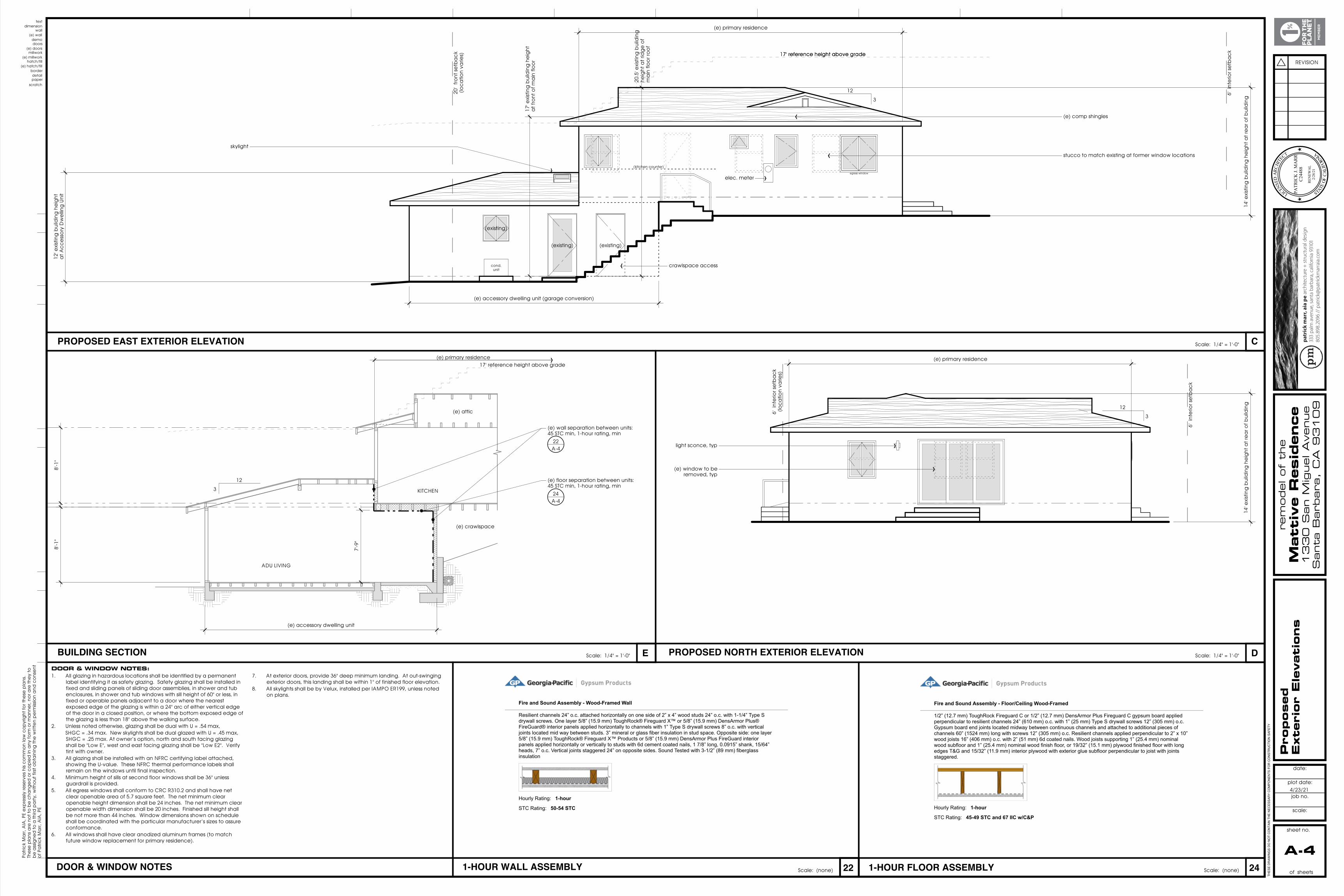
PROPOSED EAST EXTERIOR ELEVATION Scale: 1/4" = 1'-0"
detail
DBUILDING SECTION Scale: 1/4" = 1'-0" PROPOSED NORTH EXTERIOR ELEVATION Scale: 1/4" = 1'-0"E
221-HOUR WALL ASSEMBLY 1-HOUR FLOOR ASSEMBLY Scale: (none)Scale: (none)DOOR & WINDOW NOTES
THES
E DR
AWIN
GS
DO N
OT
CONT
AIN
THE
NECE
SSAR
Y CO
MPO
NENT
S FO
R CO
NSTR
UCTI
ON
SAFE
TY
sheet no.
date:
plot date:
job no.
scale:
REVISION
Patr
ick
Ma
rr, A
IA, P
E e
xpre
ssly
rese
rve
s hi
s c
om
mo
n la
w c
op
yrig
ht fo
r the
se p
lans
. Th
ese
pla
ns a
re n
ot t
o b
e c
hang
ed
or c
op
ied
in a
ny fo
rm o
r ma
nne
r, no
r are
the
y to
b
e a
ssig
ned
to a
third
pa
rty,
with
out
firs
t ob
tain
ing
the
writ
ten
pe
rmiss
ion
and
co
nse
nt
of P
atr
ick
Ma
rr, A
IA, P
E
★★
PATR
ICK
J. M
AR
R
C24
488
R
ENEW
AL
2/28
/21
LIC
ENSE
DA
RCH
ITEC
T
STATEOF
CA
LIFO
RNIA
border(e) hatch/fill
hatch/fill(e) millwork
6'
int
erio
r se
tba
ck
6' i
nte
rior s
etb
ac
k (lo
ca
tion
varie
s)
20
' fro
nt s
etb
ac
k (lo
ca
tion
varie
s)
6'
int
erio
r se
tba
ckmillwork
cond. unit
(kitchen counter)
(existing)
(e) doors
(existing) (existing)
doors
crawlspace access
17' reference height above grade
17' reference height above grade
3
12
3
12
3
12
egress window
17' reference height above grade
demo(e) wall
walldimension
8'-1
"
7'-9
"
(e) primary residence
(e) accessory dwelling unit (garage conversion)
8'-1
"
(e) primary residence
14' e
xist
ing
bui
ldin
g h
eig
ht a
t re
ar o
f bui
ldin
g
12' e
xist
ing
bui
ldin
g h
eig
ht
at A
cc
ess
ory
Dw
ellin
g U
nit
17' e
xist
ing
bui
ldin
g h
eig
ht
at f
ront
of m
ain
flo
or
20.5
' exi
stin
g b
uild
ing
heig
ht a
t rid
ge
of
ma
in fl
oo
r ro
of
14' e
xist
ing
bui
ldin
g h
eig
ht a
t re
ar o
f bui
ldin
g
(e) accessory dwelling unit
text
A-4 of sheets
Pro
posed
Exte
rior
Ele
vati
ons
4/23/21
stucco to match existing at former window locations
(e) comp shingles
elec. meter
5/3/17, 8)32 AMGeorgia-Pacific Gypsum Assemblies
Page 1 of 1http://www.buildgp.com/GypsumAssemblyPrint.aspx?id=6
Fire and Sound Assembly - Wood-Framed Wall
Resilient channels 24” o.c. attached horizontally on one side of 2” x 4” wood studs 24” o.c. with 1-1/4” Type Sdrywall screws. One layer 5/8” (15.9 mm) ToughRock® Fireguard X™ or 5/8” (15.9 mm) DensArmor Plus®FireGuard® interior panels applied horizontally to channels with 1” Type S drywall screws 8” o.c. with verticaljoints located mid way between studs. 3” mineral or glass fiber insulation in stud space. Opposite side: one layer5/8” (15.9 mm) ToughRock® Fireguard X™ Products or 5/8” (15.9 mm) DensArmor Plus FireGuard interiorpanels applied horizontally or vertically to studs with 6d cement coated nails, 1 7/8” long, 0.0915” shank, 15/64”heads, 7” o.c. Vertical joints staggered 24” on opposite sides. Sound Tested with 3-1/2” (89 mm) fiberglassinsulation
Hourly Rating: 1-hour
STC Rating: 50-54 STC
Fire Test Reference: UL U309, cUL U309, GA WP 3243
Sound Test Reference: RAL TL77-138
Approved for Assembly: DensArmor Plus® Fireguard C® ProductsDensArmor Plus® Fireguard® ProductsDensElement™ Barrier SheathingDensGlass® Fireguard® SheathingDensShield® Fireguard® Tile BackerToughRock® Fireguard C® ProductsToughRock® Fireguard X™ Mold-Guard™ ProductsToughRock® Fireguard X™ ProductsToughRock® Lite-Weight Fire-Rated Products
1. DensArmor Plus Fireguard: For certain proprietary ULC assemblies identified above, DensArmor Plus® Fireguard C® (Type DAPC) interior panels havenot been approved by ULC for listing in such assemblies as of the date of this publication in lieu of DensArmor Plus® Fireguard® High-Performance(Type DAP) interior panels. Please check with ULC for current information.n.
2. Proprietary GA-600 Designs: Assemblies listed as proprietary in the GA-600 Fire Resistance Design Manual only list one product per manufacturer andmay not include all products referenced in the illustrations above. Please consult the specified UL, cUL, ULC or other fire listing or test for a complete listof approved products.
3. ToughRock® Lite-Weight Fire-Rated: For ULC assemblies identified above, ToughRock® Lite-Weight Fire-Rated Gypsum Board (Type LWX) is notapproved by ULC for listing in such assemblies as of the date of this publication. Please check with ULC for current information.
Created and Printed – 5/3/2017 – on gpgypsum.com
© 2017. Georgia-Pacific Gypsum LLC. All rights reserved.Unless otherwise noted, all trademarks, including the Georgia-Pacific logo, are owned by or licensed to Georgia-Pacific Gypsum LLC.
5/3/17, 8)31 AMGeorgia-Pacific Gypsum Assemblies
Page 1 of 1http://www.buildgp.com/GypsumAssemblyPrint.aspx?id=42
Fire and Sound Assembly - Floor/Ceiling Wood-Framed
1/2” (12.7 mm) ToughRock Fireguard C or 1/2” (12.7 mm) DensArmor Plus Fireguard C gypsum board appliedperpendicular to resilient channels 24” (610 mm) o.c. with 1” (25 mm) Type S drywall screws 12” (305 mm) o.c.Gypsum board end joints located midway between continuous channels and attached to additional pieces ofchannels 60” (1524 mm) long with screws 12” (305 mm) o.c. Resilient channels applied perpendicular to 2” x 10”wood joists 16” (406 mm) o.c. with 2” (51 mm) 6d coated nails. Wood joists supporting 1” (25.4 mm) nominalwood subfloor and 1” (25.4 mm) nominal wood finish floor, or 19/32” (15.1 mm) plywood finished floor with longedges T&G and 15/32” (11.9 mm) interior plywood with exterior glue subfloor perpendicular to joist with jointsstaggered.
Hourly Rating: 1-hour
STC Rating: 45-49 STC and 67 IIC w/C&P
Fire Test Reference: UL L502, ULC M501, cUL L502, GA FC 5250
Sound Test Reference: RAL TL64-155 & IIC - CK 6512-6
Approved for Assembly: ToughRock® Fireguard C® ProductsDensArmor Plus® Fireguard C® Products
1. DensArmor Plus Fireguard: For certain proprietary ULC assemblies identified above, DensArmor Plus® Fireguard C® (Type DAPC) interior panels havenot been approved by ULC for listing in such assemblies as of the date of this publication in lieu of DensArmor Plus® Fireguard® High-Performance(Type DAP) interior panels. Please check with ULC for current information.n.
2. Proprietary GA-600 Designs: Assemblies listed as proprietary in the GA-600 Fire Resistance Design Manual only list one product per manufacturer andmay not include all products referenced in the illustrations above. Please consult the specified UL, cUL, ULC or other fire listing or test for a complete listof approved products.
3. ToughRock® Lite-Weight Fire-Rated: For ULC assemblies identified above, ToughRock® Lite-Weight Fire-Rated Gypsum Board (Type LWX) is notapproved by ULC for listing in such assemblies as of the date of this publication. Please check with ULC for current information.
Created and Printed – 5/3/2017 – on gpgypsum.com
© 2017. Georgia-Pacific Gypsum LLC. All rights reserved.Unless otherwise noted, all trademarks, including the Georgia-Pacific logo, are owned by or licensed to Georgia-Pacific Gypsum LLC.
DOOR & WINDOW NOTES:1. All glazing in hazardous locations shall be identified by a permanent
label identifying it as safety glazing. Safety glazing shall be installed in fixed and sliding panels of sliding door assemblies, in shower and tub enclosures, in shower and tub windows with sill height of 60" or less, in fixed or operable panels adjacent to a door where the nearest exposed edge of the glazing is within a 24" arc of either vertical edge of the door in a closed position, or where the bottom exposed edge of the glazing is less than 18" above the walking surface.
2. Unless noted otherwise, glazing shall be dual with U = .54 max, SHGC = .34 max. New skylights shall be dual glazed with U = .45 max, SHGC = .25 max. At owner’s option, north and south facing glazing shall be "Low E", west and east facing glazing shall be "Low E2". Verify tint with owner.
3. All glazing shall be installed with an NFRC certifying label attached, showing the U-value. These NFRC thermal performance labels shall remain on the windows until final inspection.
4. Minimum height of sills at second floor windows shall be 36" unless guardrail is provided.
5. All egress windows shall conform to CRC R310.2 and shall have net clear openable area of 5.7 square feet. The net minimum clear openable height dimension shall be 24 inches. The net minimum clear openable width dimension shall be 20 inches. Finished sill height shall be not more than 44 inches. Window dimensions shown on schedule shall be coordinated with the particular manufacturer’s sizes to assure conformance.
6. All windows shall have clear anodized aluminum frames (to match future window replacement for primary residence).
7. At exterior doors, provide 36" deep minimum landing. At out-swinging
exterior doors, this landing shall be within 1" of finished floor elevation.8. All skylights shall be by Velux, installed per IAMPO ER199, unless noted
on plans.
skylight
rem
odel of
the
Matt
ive R
esid
ence
133
0 S
an M
iguel A
venue
Santa
Barb
ara
, C
A 9
31
09
(e) wall separation between units: 45 STC min, 1-hour rating, min
(e) floor separation between units: 45 STC min, 1-hour rating, min
24A-4
22A-4
(e) primary residence
ADU LIVING
KITCHEN
(e) attic
(e) crawlspace
(e) window to be removed, typ
light sconce, typ