matlab - forside · the layout editor ... creating menus — the menu editor ... the matlab®...
TRANSCRIPT

Creating Graphical User InterfacesVersion 7
MATLAB®
The Language of Technical Computing
How to Contact The MathWorks:
www.mathworks.com Webcomp.soft-sys.matlab Newsgroup
[email protected] Technical [email protected] Product enhancement [email protected] Bug [email protected] Documentation error [email protected] Order status, license renewals, [email protected] Sales, pricing, and general information
508-647-7000 Phone
508-647-7001 Fax
The MathWorks, Inc. Mail3 Apple Hill DriveNatick, MA 01760-2098
For contact information about worldwide offices, see the MathWorks Web site.
MATLAB Creating Graphical User Interfaces © COPYRIGHT 2000 - 2005 by The MathWorks, Inc. The software described in this document is furnished under a license agreement. The software may be used or copied only under the terms of the license agreement. No part of this manual may be photocopied or repro-duced in any form without prior written consent from The MathWorks, Inc.
FEDERAL ACQUISITION: This provision applies to all acquisitions of the Program and Documentation by, for, or through the federal government of the United States. By accepting delivery of the Program or Documentation, the government hereby agrees that this software or documentation qualifies as commercial computer software or commercial computer software documentation as such terms are used or defined in FAR 12.212, DFARS Part 227.72, and DFARS 252.227-7014. Accordingly, the terms and conditions of this Agreement and only those rights specified in this Agreement, shall pertain to and govern the use, modification, reproduction, release, performance, display, and disclosure of the Program and Documentation by the federal government (or other entity acquiring for or through the federal government) and shall supersede any conflicting contractual terms or conditions. If this License fails to meet the government's needs or is inconsistent in any respect with federal procurement law, the government agrees to return the Program and Documentation, unused, to The MathWorks, Inc.
MATLAB, Simulink, Stateflow, Handle Graphics, Real-Time Workshop, and xPC TargetBox are registered trademarks of The MathWorks, Inc.
Other product or brand names are trademarks or registered trademarks of their respective holders.
Printing History: November 2000 Online only New for MATLAB 6.0 (Release12)June 2001 Online only Revised for MATLAB 6.1 (Release 12.1)July 2002 Online only Revised for MATLAB 6.5 (Release 13)June 2004 Online only Revised for MATLAB 7.0 (Release 14)October 2004 Online only Revised for MATLAB 7.0.1 (Release 14SP1)March 2005 Online only Revised for MATLAB 7.0.4 (Release 14SP2)
i
Contents
1Getting Started with GUIDE
What Is GUIDE? . . . . . . . . . . . . . . . . . . . . . . . . . . . . . . . . . . . . . . 1-2
Starting GUIDE . . . . . . . . . . . . . . . . . . . . . . . . . . . . . . . . . . . . . . 1-3
The Layout Editor . . . . . . . . . . . . . . . . . . . . . . . . . . . . . . . . . . . . 1-4
GUIDE Templates . . . . . . . . . . . . . . . . . . . . . . . . . . . . . . . . . . . . . 1-6
Running a GUI . . . . . . . . . . . . . . . . . . . . . . . . . . . . . . . . . . . . . . . 1-8
GUI FIG-Files and M-Files . . . . . . . . . . . . . . . . . . . . . . . . . . . . . 1-9
Programming the GUI M-file . . . . . . . . . . . . . . . . . . . . . . . . . . 1-10
Editing Version 5 GUIs with Version 7 GUIDE . . . . . . . . . . 1-12Saving the GUI in Version 7 GUIDE . . . . . . . . . . . . . . . . . . . . 1-12Updating Callbacks . . . . . . . . . . . . . . . . . . . . . . . . . . . . . . . . . . 1-13
2Creating a GUI
Designing the GUI . . . . . . . . . . . . . . . . . . . . . . . . . . . . . . . . . . . . 2-2
Laying Out the GUI . . . . . . . . . . . . . . . . . . . . . . . . . . . . . . . . . . . 2-3View Layout and Code for the Example . . . . . . . . . . . . . . . . . . . 2-3Open a New GUI in the Layout Editor . . . . . . . . . . . . . . . . . . . 2-4Set the GUI Figure Size . . . . . . . . . . . . . . . . . . . . . . . . . . . . . . . 2-6Add the Components . . . . . . . . . . . . . . . . . . . . . . . . . . . . . . . . . . 2-7Align the Components . . . . . . . . . . . . . . . . . . . . . . . . . . . . . . . . . 2-9
ii Contents
Setting Properties for GUI Components . . . . . . . . . . . . . . . . 2-11Name Property . . . . . . . . . . . . . . . . . . . . . . . . . . . . . . . . . . . . . . 2-11Title Property . . . . . . . . . . . . . . . . . . . . . . . . . . . . . . . . . . . . . . . 2-12String Property for Push Buttons and Static Text . . . . . . . . . . 2-12String Property for Pop-up Menus . . . . . . . . . . . . . . . . . . . . . . 2-12Callback Properties . . . . . . . . . . . . . . . . . . . . . . . . . . . . . . . . . . 2-14The Tag Property . . . . . . . . . . . . . . . . . . . . . . . . . . . . . . . . . . . . 2-14
Programming the GUI . . . . . . . . . . . . . . . . . . . . . . . . . . . . . . . . 2-17Creating the GUI M-File . . . . . . . . . . . . . . . . . . . . . . . . . . . . . . 2-17Opening the GUI M-File . . . . . . . . . . . . . . . . . . . . . . . . . . . . . . 2-17Sharing Data Between Callbacks . . . . . . . . . . . . . . . . . . . . . . . 2-19Adding Code to the Opening Function . . . . . . . . . . . . . . . . . . . 2-20Adding Code to the Callbacks . . . . . . . . . . . . . . . . . . . . . . . . . . 2-22Using the Object Browser to Identify Callbacks . . . . . . . . . . . 2-24
Saving and Running a GUI . . . . . . . . . . . . . . . . . . . . . . . . . . . . 2-26
3Laying Out GUIs and Setting Properties
Using GUIDE Templates . . . . . . . . . . . . . . . . . . . . . . . . . . . . . . . 3-2Blank GUI . . . . . . . . . . . . . . . . . . . . . . . . . . . . . . . . . . . . . . . . . . 3-3GUI with Uicontrols . . . . . . . . . . . . . . . . . . . . . . . . . . . . . . . . . . . 3-4GUI with Axes and Menu . . . . . . . . . . . . . . . . . . . . . . . . . . . . . . 3-5Modal Question Dialog . . . . . . . . . . . . . . . . . . . . . . . . . . . . . . . . 3-6
Using the Layout Editor . . . . . . . . . . . . . . . . . . . . . . . . . . . . . . . 3-9Starting the Layout Editor . . . . . . . . . . . . . . . . . . . . . . . . . . . . . 3-9Selecting Components from the Component Palette . . . . . . . . 3-10Adding Components to the Layout Area . . . . . . . . . . . . . . . . . . 3-13Working with Components in the Layout Area . . . . . . . . . . . . 3-16Running the GUI . . . . . . . . . . . . . . . . . . . . . . . . . . . . . . . . . . . . 3-19Saving the Layout . . . . . . . . . . . . . . . . . . . . . . . . . . . . . . . . . . . 3-21Renaming GUI Files . . . . . . . . . . . . . . . . . . . . . . . . . . . . . . . . . 3-21Exporting a GUI to a Single M-File . . . . . . . . . . . . . . . . . . . . . 3-21Displaying the GUI . . . . . . . . . . . . . . . . . . . . . . . . . . . . . . . . . . 3-22
iii
Layout Editor Preferences . . . . . . . . . . . . . . . . . . . . . . . . . . . . . 3-22Layout Editor Context Menus . . . . . . . . . . . . . . . . . . . . . . . . . . 3-27
Selecting GUI Options . . . . . . . . . . . . . . . . . . . . . . . . . . . . . . . . 3-29Configuring the GUI M-File . . . . . . . . . . . . . . . . . . . . . . . . . . . 3-29Resize Behavior . . . . . . . . . . . . . . . . . . . . . . . . . . . . . . . . . . . . . 3-30Command-Line Accessibility . . . . . . . . . . . . . . . . . . . . . . . . . . . 3-31Generate FIG-File and M-File . . . . . . . . . . . . . . . . . . . . . . . . . . 3-33Generate Callback Function Prototypes . . . . . . . . . . . . . . . . . . 3-34GUI Allows Only One Instance to Run (Singleton) . . . . . . . . . 3-36Using the System Background Colors . . . . . . . . . . . . . . . . . . . 3-36Generate FIG-File Only . . . . . . . . . . . . . . . . . . . . . . . . . . . . . . . 3-37
Aligning Components in the Layout Editor . . . . . . . . . . . . . 3-38Aligning Groups of Components — The Alignment Tool . . . . . 3-38Grids and Rulers . . . . . . . . . . . . . . . . . . . . . . . . . . . . . . . . . . . . 3-40Aligning Components to Guide Lines . . . . . . . . . . . . . . . . . . . . 3-41Front-to-Back Positioning . . . . . . . . . . . . . . . . . . . . . . . . . . . . . 3-42
Setting Component Properties — The Property Inspector 3-44Displaying the Property Inspector . . . . . . . . . . . . . . . . . . . . . . 3-44What Properties Do I Need to Set? . . . . . . . . . . . . . . . . . . . . . . 3-45Some Commonly Used Properties . . . . . . . . . . . . . . . . . . . . . . . 3-46Setting Properties for Some Specific Components . . . . . . . . . . 3-48Callback Properties . . . . . . . . . . . . . . . . . . . . . . . . . . . . . . . . . . 3-55Changing Tag and Callback Properties . . . . . . . . . . . . . . . . . . 3-57
Viewing the Object Hierarchy — The Object Browser . . . 3-60
Creating Menus — The Menu Editor . . . . . . . . . . . . . . . . . . . 3-61Defining Menus for the Menu Bar . . . . . . . . . . . . . . . . . . . . . . 3-62Menu Callbacks . . . . . . . . . . . . . . . . . . . . . . . . . . . . . . . . . . . . . 3-67Defining Context Menus . . . . . . . . . . . . . . . . . . . . . . . . . . . . . . 3-69
Setting the Tab Order . . . . . . . . . . . . . . . . . . . . . . . . . . . . . . . . 3-73The GUIDE Tab Order Editor . . . . . . . . . . . . . . . . . . . . . . . . . . 3-73Setting the Tab Order Programmatically . . . . . . . . . . . . . . . . . 3-75
iv Contents
4Programming GUIs
Understanding the GUI M-File . . . . . . . . . . . . . . . . . . . . . . . . . 4-2Sharing Data with the Handles Structure . . . . . . . . . . . . . . . . . 4-2Functions and Callbacks in the M-File . . . . . . . . . . . . . . . . . . . . 4-3Opening Function . . . . . . . . . . . . . . . . . . . . . . . . . . . . . . . . . . . . . 4-4Output Function . . . . . . . . . . . . . . . . . . . . . . . . . . . . . . . . . . . . . . 4-5Callbacks . . . . . . . . . . . . . . . . . . . . . . . . . . . . . . . . . . . . . . . . . . . 4-6Input and Output Arguments . . . . . . . . . . . . . . . . . . . . . . . . . . . 4-7
Programming Callbacks for GUI Components . . . . . . . . . . . 4-8Toggle Button Callback . . . . . . . . . . . . . . . . . . . . . . . . . . . . . . . . 4-8Radio Buttons . . . . . . . . . . . . . . . . . . . . . . . . . . . . . . . . . . . . . . . . 4-9Check Boxes . . . . . . . . . . . . . . . . . . . . . . . . . . . . . . . . . . . . . . . 4-10Edit Text . . . . . . . . . . . . . . . . . . . . . . . . . . . . . . . . . . . . . . . . . . 4-10Sliders . . . . . . . . . . . . . . . . . . . . . . . . . . . . . . . . . . . . . . . . . . . . . 4-11List Boxes . . . . . . . . . . . . . . . . . . . . . . . . . . . . . . . . . . . . . . . . . 4-11Pop-Up Menus . . . . . . . . . . . . . . . . . . . . . . . . . . . . . . . . . . . . . . 4-12Panels . . . . . . . . . . . . . . . . . . . . . . . . . . . . . . . . . . . . . . . . . . . . . 4-13Button Groups . . . . . . . . . . . . . . . . . . . . . . . . . . . . . . . . . . . . . . 4-13Axes . . . . . . . . . . . . . . . . . . . . . . . . . . . . . . . . . . . . . . . . . . . . . . . 4-14ActiveX Controls . . . . . . . . . . . . . . . . . . . . . . . . . . . . . . . . . . . . 4-17Figures . . . . . . . . . . . . . . . . . . . . . . . . . . . . . . . . . . . . . . . . . . . . 4-25
Managing GUI Data with the Handles Structure . . . . . . . . 4-27Example: Passing Data Between Callbacks . . . . . . . . . . . . . . . 4-27
Managing Application Data . . . . . . . . . . . . . . . . . . . . . . . . . . . 4-31
Designing for Cross-Platform Compatibility . . . . . . . . . . . . 4-32Using the Default System Font . . . . . . . . . . . . . . . . . . . . . . . . . 4-32Using Standard Background Color . . . . . . . . . . . . . . . . . . . . . . 4-33Cross-Platform Compatible Figure Units . . . . . . . . . . . . . . . . . 4-34
Types of Callbacks . . . . . . . . . . . . . . . . . . . . . . . . . . . . . . . . . . . 4-35Callback Properties for All Graphics Objects . . . . . . . . . . . . . . 4-35Callback Properties for Figures . . . . . . . . . . . . . . . . . . . . . . . . 4-35Callbacks for Specific Components . . . . . . . . . . . . . . . . . . . . . . 4-36
v
Which Callback Executes . . . . . . . . . . . . . . . . . . . . . . . . . . . . . 4-36Adding a Callback . . . . . . . . . . . . . . . . . . . . . . . . . . . . . . . . . . . 4-36
Interrupting Executing Callbacks . . . . . . . . . . . . . . . . . . . . . 4-37Controlling Interruptibility . . . . . . . . . . . . . . . . . . . . . . . . . . . . 4-37The Event Queue . . . . . . . . . . . . . . . . . . . . . . . . . . . . . . . . . . . . 4-37Event Processing During Callback Execution . . . . . . . . . . . . . 4-38
Controlling Figure Window Behavior . . . . . . . . . . . . . . . . . . 4-40Using Modal Figure Windows . . . . . . . . . . . . . . . . . . . . . . . . . . 4-40
Example: Using the Modal Dialog to Confirm an Operation . . . . . . . . . . . . . . . . . . . . . . . . . . . . . . . . . . . . . . . . . . . 4-42
View Completed Layouts and Their GUI M-Files . . . . . . . . . . 4-42Setting Up the Close Confirmation Dialog . . . . . . . . . . . . . . . . 4-43Setting Up the GUI with the Close Button . . . . . . . . . . . . . . . 4-44Running the GUI with the Close Button . . . . . . . . . . . . . . . . . 4-45How the GUI and Dialog Work . . . . . . . . . . . . . . . . . . . . . . . . . 4-46
5GUI Applications
GUI with Multiple Axes . . . . . . . . . . . . . . . . . . . . . . . . . . . . . . . . 5-2Techniques Used in the Example . . . . . . . . . . . . . . . . . . . . . . . . 5-2View Completed Layout and Its GUI M-File . . . . . . . . . . . . . . . 5-3Design of the GUI . . . . . . . . . . . . . . . . . . . . . . . . . . . . . . . . . . . . 5-3Plot Push Button Callback . . . . . . . . . . . . . . . . . . . . . . . . . . . . . 5-6
List Box Directory Reader . . . . . . . . . . . . . . . . . . . . . . . . . . . . . 5-9View Layout and GUI M-File . . . . . . . . . . . . . . . . . . . . . . . . . . . 5-9Implementing the GUI . . . . . . . . . . . . . . . . . . . . . . . . . . . . . . . 5-10Specifying the Directory to List . . . . . . . . . . . . . . . . . . . . . . . . . 5-10Loading the List Box . . . . . . . . . . . . . . . . . . . . . . . . . . . . . . . . . 5-12
Accessing Workspace Variables from a List Box . . . . . . . . . 5-15Techniques Used in This Example . . . . . . . . . . . . . . . . . . . . . . 5-15View Completed Layout and Its GUI M-File . . . . . . . . . . . . . . 5-16
vi Contents
Reading Workspace Variables . . . . . . . . . . . . . . . . . . . . . . . . . . 5-16Reading the Selections from the List Box . . . . . . . . . . . . . . . . . 5-17
A GUI to Set Simulink Model Parameters . . . . . . . . . . . . . . 5-19Techniques Used in This Example . . . . . . . . . . . . . . . . . . . . . . 5-19View Completed Layout and Its GUI M-File . . . . . . . . . . . . . . 5-19How to Use the GUI (Text of GUI Help) . . . . . . . . . . . . . . . . . . 5-20Running the GUI . . . . . . . . . . . . . . . . . . . . . . . . . . . . . . . . . . . . 5-21Programming the Slider and Edit Text Components . . . . . . . . 5-22Running the Simulation from the GUI . . . . . . . . . . . . . . . . . . . 5-24Removing Results from the List Box . . . . . . . . . . . . . . . . . . . . 5-26Plotting the Results Data . . . . . . . . . . . . . . . . . . . . . . . . . . . . . 5-27The GUI Help Button . . . . . . . . . . . . . . . . . . . . . . . . . . . . . . . . 5-29Closing the GUI . . . . . . . . . . . . . . . . . . . . . . . . . . . . . . . . . . . . . 5-29The List Box Callback and Create Function . . . . . . . . . . . . . . 5-29
An Address Book Reader . . . . . . . . . . . . . . . . . . . . . . . . . . . . . 5-31Techniques Used in This Example . . . . . . . . . . . . . . . . . . . . . . 5-31Managing Shared Data . . . . . . . . . . . . . . . . . . . . . . . . . . . . . . . 5-31View Completed Layout and Its GUI M-File . . . . . . . . . . . . . . 5-32Running the GUI . . . . . . . . . . . . . . . . . . . . . . . . . . . . . . . . . . . . 5-32Loading an Address Book Into the Reader . . . . . . . . . . . . . . . . 5-34The Contact Name Callback . . . . . . . . . . . . . . . . . . . . . . . . . . . 5-36The Contact Phone Number Callback . . . . . . . . . . . . . . . . . . . . 5-38Paging Through the Address Book — Prev/Next . . . . . . . . . . . 5-39Saving Changes to the Address Book from the Menu . . . . . . . 5-41The Create New Menu . . . . . . . . . . . . . . . . . . . . . . . . . . . . . . . . 5-43The Address Book Resize Function . . . . . . . . . . . . . . . . . . . . . . 5-43
AWorking with Callbacks (Draft)
Introduction to GUI Callbacks . . . . . . . . . . . . . . . . . . . . . . . . . A-3What Is a Callback? . . . . . . . . . . . . . . . . . . . . . . . . . . . . . . . . . . . A-3Kinds of Callbacks . . . . . . . . . . . . . . . . . . . . . . . . . . . . . . . . . . . . A-3
vii
GUI Files . . . . . . . . . . . . . . . . . . . . . . . . . . . . . . . . . . . . . . . . . . . . . A-7GUIDE M-Files and FIG-Files . . . . . . . . . . . . . . . . . . . . . . . . . . A-7Files for Programmatically Created GUIs . . . . . . . . . . . . . . . . A-10
Associating Callbacks with Components . . . . . . . . . . . . . . . A-14Defining Callback Properties . . . . . . . . . . . . . . . . . . . . . . . . . . A-14Callback Properties in GUIDE . . . . . . . . . . . . . . . . . . . . . . . . . A-15
Component and Figure Callbacks . . . . . . . . . . . . . . . . . . . . . A-17Callback Conventions in GUIDE . . . . . . . . . . . . . . . . . . . . . . . A-17Callbacks in Programmatically Created GUIs . . . . . . . . . . . . . A-20
Initialization Callbacks in GUIDE . . . . . . . . . . . . . . . . . . . . . A-23Opening Function . . . . . . . . . . . . . . . . . . . . . . . . . . . . . . . . . . . . A-23Output Function . . . . . . . . . . . . . . . . . . . . . . . . . . . . . . . . . . . . . A-25
Managing Application-Defined Data . . . . . . . . . . . . . . . . . . . A-27Mechanisms for Managing Data . . . . . . . . . . . . . . . . . . . . . . . . A-27Adding Fields to a Data Structure . . . . . . . . . . . . . . . . . . . . . . A-30Sharing Data Among a GUI’s Callbacks . . . . . . . . . . . . . . . . . . A-31
Properties That Control Component Behavior . . . . . . . . . . A-35General Information About the Component . . . . . . . . . . . . . . . A-35Information About Component State . . . . . . . . . . . . . . . . . . . . A-36Properties that Affect Callback Execution . . . . . . . . . . . . . . . . A-37Properties that Affect Component Access . . . . . . . . . . . . . . . . . A-39
Examples of Callbacks for GUI Components . . . . . . . . . . . . A-40Toggle Button Callback . . . . . . . . . . . . . . . . . . . . . . . . . . . . . . . A-40Radio Buttons . . . . . . . . . . . . . . . . . . . . . . . . . . . . . . . . . . . . . . . A-41Check Boxes . . . . . . . . . . . . . . . . . . . . . . . . . . . . . . . . . . . . . . . A-42Edit Text . . . . . . . . . . . . . . . . . . . . . . . . . . . . . . . . . . . . . . . . . . A-42Sliders . . . . . . . . . . . . . . . . . . . . . . . . . . . . . . . . . . . . . . . . . . . . . A-43List Boxes . . . . . . . . . . . . . . . . . . . . . . . . . . . . . . . . . . . . . . . . . A-43Pop-Up Menus . . . . . . . . . . . . . . . . . . . . . . . . . . . . . . . . . . . . . . A-44Panels . . . . . . . . . . . . . . . . . . . . . . . . . . . . . . . . . . . . . . . . . . . . . A-45Button Groups . . . . . . . . . . . . . . . . . . . . . . . . . . . . . . . . . . . . . . A-45Axes . . . . . . . . . . . . . . . . . . . . . . . . . . . . . . . . . . . . . . . . . . . . . . . A-46ActiveX Controls . . . . . . . . . . . . . . . . . . . . . . . . . . . . . . . . . . . . A-49

viii Contents
Index
1Getting Started with GUIDE
What Is GUIDE? (p. 1-2) An introduction to GUIDE
Starting GUIDE (p. 1-3) How to start GUIDE and use the Quick Start dialog
The Layout Editor (p. 1-4) The Layout Editor enables you to lay out the GUI components quickly and easily
GUIDE Templates (p. 1-6) GUIDE templates are simple, pre-constructed GUIs that you can modify for your own purposes
Running a GUI (p. 1-8) How to run a GUI
GUI FIG-Files and M-Files (p. 1-9) GUIDE stores GUIs in two files, a FIG-file that contains the layout, and an M-file that controls the GUI
Programming the GUI M-file (p. 1-10) The GUI M-file controls how the GUI functions
Editing Version 5 GUIs with Version 7 GUIDE (p. 1-12)
Editing GUIs created in GUIDE Version 5
1 Getting Started with GUIDE
1-2
What Is GUIDE?GUIDE, the MATLAB® Graphical User Interface development environment, provides a set of tools for creating graphical user interfaces (GUIs). These tools greatly simplify the process of designing and building GUIs. You can use the GUIDE tools to
• Lay out the GUI
Using the GUIDE Layout Editor, you can lay out a GUI easily by clicking and dragging GUI components — such as panels, buttons, text fields, sliders, menus, and so on — into the layout area.
• Program the GUI
GUIDE automatically generates an M-file that controls how the GUI operates. The M-file initializes the GUI and contains a framework for all the GUI callbacks — the commands that are executed when a user clicks a GUI component. Using the M-file editor, you can add code to the callbacks to perform the functions you want them to.
The following sections provide an overview of creating GUIs with GUIDE.
Starting GUIDE
1-3
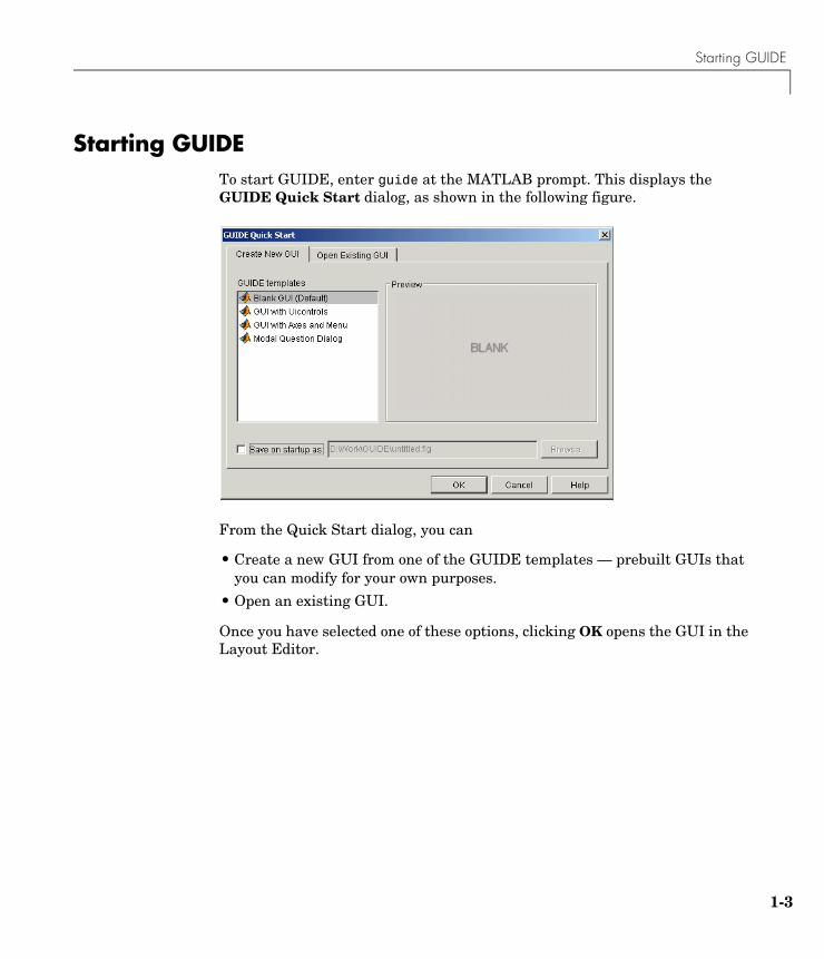
Starting GUIDETo start GUIDE, enter guide at the MATLAB prompt. This displays the GUIDE Quick Start dialog, as shown in the following figure.
From the Quick Start dialog, you can
• Create a new GUI from one of the GUIDE templates — prebuilt GUIs that you can modify for your own purposes.
• Open an existing GUI.
Once you have selected one of these options, clicking OK opens the GUI in the Layout Editor.
1 Getting Started with GUIDE
1-4
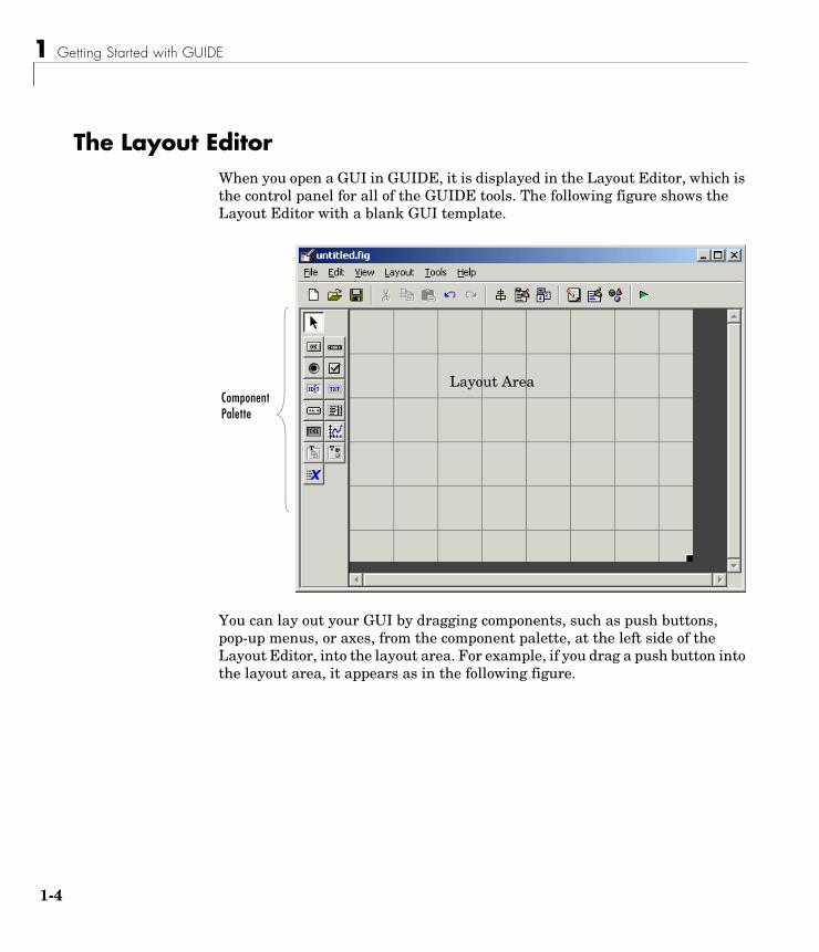
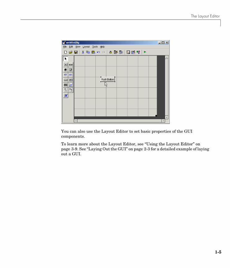
The Layout EditorWhen you open a GUI in GUIDE, it is displayed in the Layout Editor, which is the control panel for all of the GUIDE tools. The following figure shows the Layout Editor with a blank GUI template.
You can lay out your GUI by dragging components, such as push buttons, pop-up menus, or axes, from the component palette, at the left side of the Layout Editor, into the layout area. For example, if you drag a push button into the layout area, it appears as in the following figure.
Component Palette
Layout Area
The Layout Editor
1-5
You can also use the Layout Editor to set basic properties of the GUI components.
To learn more about the Layout Editor, see “Using the Layout Editor” on page 3-9. See “Laying Out the GUI” on page 2-3 for a detailed example of laying out a GUI.
1 Getting Started with GUIDE
1-6
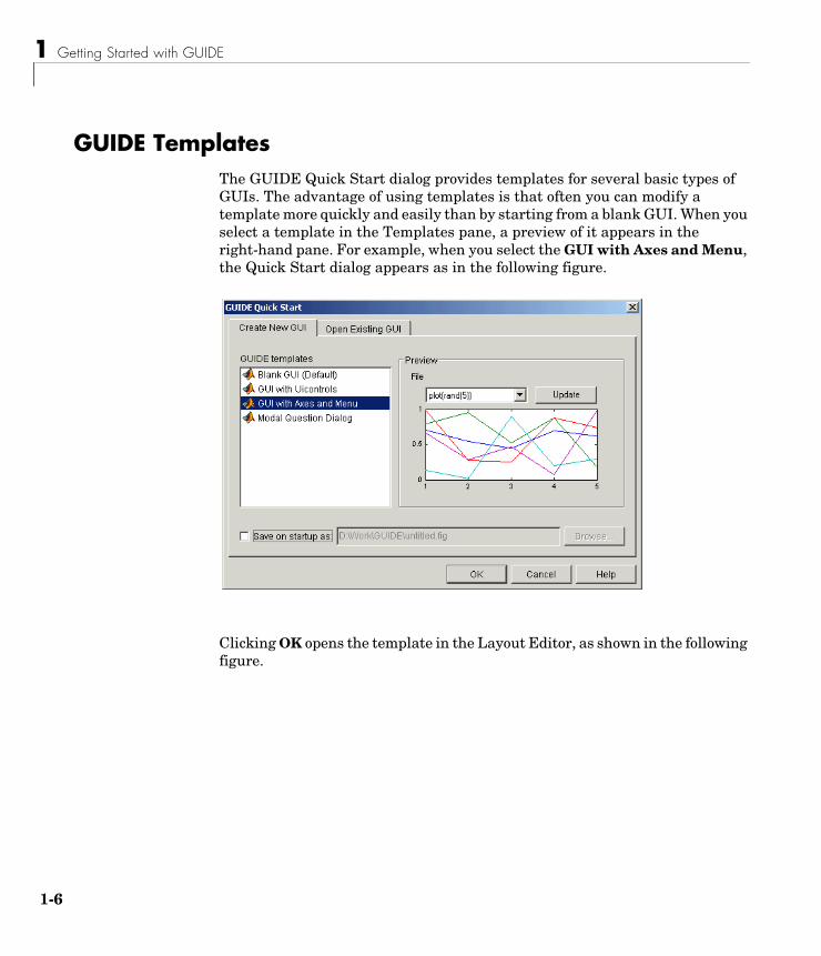
GUIDE TemplatesThe GUIDE Quick Start dialog provides templates for several basic types of GUIs. The advantage of using templates is that often you can modify a template more quickly and easily than by starting from a blank GUI. When you select a template in the Templates pane, a preview of it appears in the right-hand pane. For example, when you select the GUI with Axes and Menu, the Quick Start dialog appears as in the following figure.
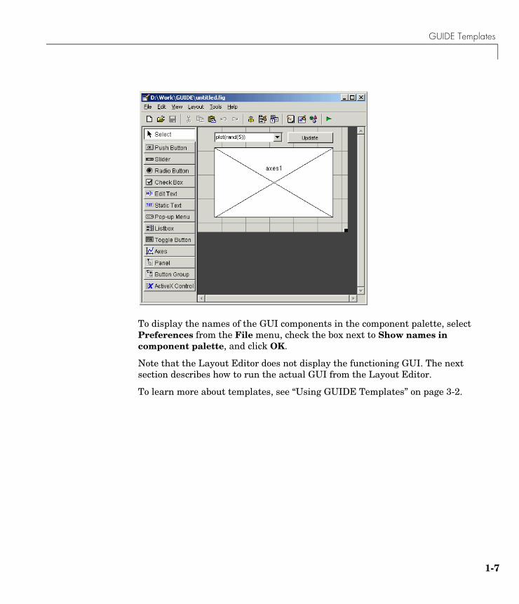
Clicking OK opens the template in the Layout Editor, as shown in the following figure.
GUIDE Templates
1-7
To display the names of the GUI components in the component palette, select Preferences from the File menu, check the box next to Show names in component palette, and click OK.
Note that the Layout Editor does not display the functioning GUI. The next section describes how to run the actual GUI from the Layout Editor.
To learn more about templates, see “Using GUIDE Templates” on page 3-2.
1 Getting Started with GUIDE
1-8
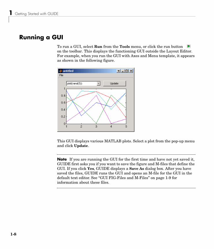
Running a GUITo run a GUI, select Run from the Tools menu, or click the run button on the toolbar. This displays the functioning GUI outside the Layout Editor. For example, when you run the GUI with Axes and Menu template, it appears as shown in the following figure.
This GUI displays various MATLAB plots. Select a plot from the pop-up menu and click Update.
Note If you are running the GUI for the first time and have not yet saved it, GUIDE first asks you if you want to save the figure and M-files that define the GUI. If you click Yes, GUIDE displays a Save As dialog box. After you have saved the files, GUIDE runs the GUI and opens an M-file for the GUI in the default text editor. See “GUI FIG-Files and M-Files” on page 1-9 for information about these files.
GUI FIG-Files and M-Files
1-9
GUI FIG-Files and M-FilesGUIDE stores a GUI in two files, which are generated the first time you save or run the GUI:
• A FIG-file, with extension .fig, which contains a complete description of the GUI layout and the components of the GUI: push buttons, menus, axes, and so on.
• An M-file, with extension .m, that contains the code that controls the GUI, including the callbacks for its components.
These two files correspond to the tasks of laying out and programming the GUI. When you lay out of the GUI in the Layout Editor, your work is stored in the FIG-file. When you program the GUI, your work is stored in the M-file.
1 Getting Started with GUIDE
1-10
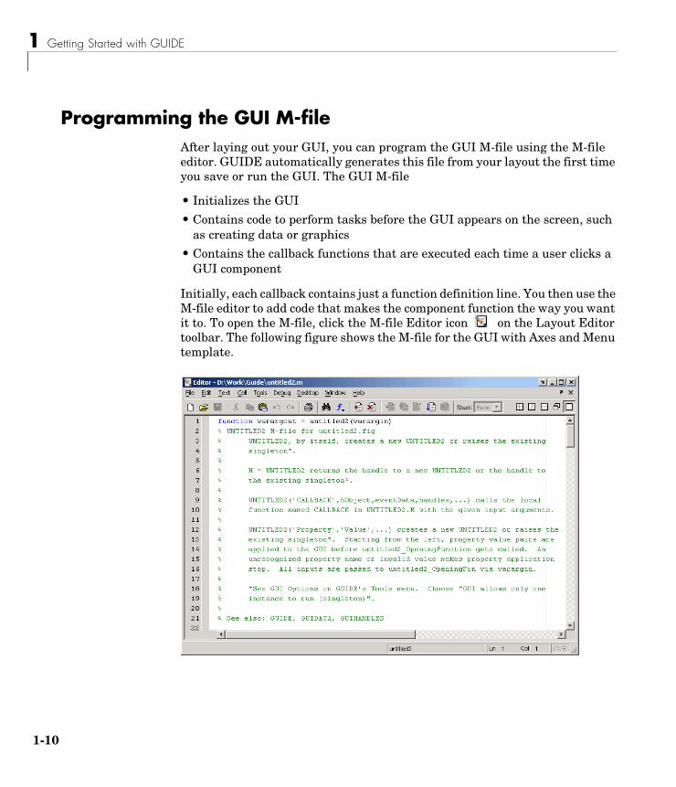
Programming the GUI M-fileAfter laying out your GUI, you can program the GUI M-file using the M-file editor. GUIDE automatically generates this file from your layout the first time you save or run the GUI. The GUI M-file
• Initializes the GUI
• Contains code to perform tasks before the GUI appears on the screen, such as creating data or graphics
• Contains the callback functions that are executed each time a user clicks a GUI component
Initially, each callback contains just a function definition line. You then use the M-file editor to add code that makes the component function the way you want it to. To open the M-file, click the M-file Editor icon on the Layout Editor toolbar. The following figure shows the M-file for the GUI with Axes and Menu template.
Programming the GUI M-file
1-11
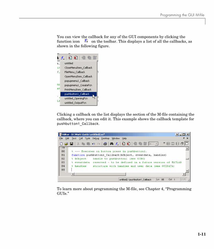
You can view the callback for any of the GUI components by clicking the function icon on the toolbar. This displays a list of all the callbacks, as shown in the following figure.
Clicking a callback on the list displays the section of the M-file containing the callback, where you can edit it. This example shows the callback template for pushbutton1_Callback.
To learn more about programming the M-file, see Chapter 4, “Programming GUIs.”
1 Getting Started with GUIDE
1-12
Editing Version 5 GUIs with Version 7 GUIDEIn MATLAB Version 5, GUIDE saved GUI layouts as MAT-file/M-file pairs. Since MATLAB Version 6, GUIDE saves GUI layouts as FIG-files. GUIDE also generates an M-file to program the GUI callbacks. However, this M-file does not contain layout code as did M-files created in Version 5.
Use the following procedure to edit a Version 5 GUI with Version 7 GUIDE:
1 Display the Version 5 GUI.
2 Obtain the handle of the GUI figure. If the figure’s handle is hidden (i.e., the figure’s HandleVisibility property is set to off), set the root ShowHiddenHandles property to on:
set(0,'ShowHiddenHandles','on')
Then get the handle from the root’s Children property:
hObject = get(0,'Children');
This statement returns the handles of all figures that exist when you issue the command. For simplicity, ensure that the GUI is the only figure displayed.
3 Pass the handle as an argument to the guide command:
guide(hObject)
Saving the GUI in Version 7 GUIDEWhen you save the edited GUI with Version 7 GUIDE, MATLAB creates a FIG-file that contains all the layout information. The original MAT-file/M-file combination is no longer used. To display the revised GUI, run the M-file generated by GUIDE.
Editing Version 5 GUIs with Version 7 GUIDE
1-13
Note GUI FIG-files that are created or modified with MATLAB 7.0 or a later MATLAB version, are not automatically compatible with Version 6.5 and earlier versions. To make a FIG-file, which is a kind of MAT-file, backward compatible, you must check the MAT-file Ensure backward compatibility (-v6) preference in the Preferences dialog box under General -> MAT-Files.
Updating CallbacksEnsure that the Callback properties of the uicontrols in your GUI are set to the desired callback string or callback M-file name when you save the FIG-file. If your Version 5 GUI used an M-file that contained a combination of layout code and callback routines, then you should restructure the M-file to contain only the commands needed to initialize the GUI and the callback functions. The M-file generated by Version 7 GUIDE can provide a model of how to restructure your code.

1 Getting Started with GUIDE
1-14
2
Creating a GUI
Designing the GUI (p. 2-2) Designing the GUI before actually creating it in GUIDE.
Laying Out the GUI (p. 2-3) Using the GUIDE Layout Editor to arrange the GUI components, such as push buttons, pop-up menus, and axes.
Setting Properties for GUI Components (p. 2-11)
Setting properties for each GUI component.
Programming the GUI (p. 2-17) Using the M-file editor to program the GUI.
Saving and Running a GUI (p. 2-26) Saving and running the GUI from the Layout Editor.
2 Creating a GUI
2-2
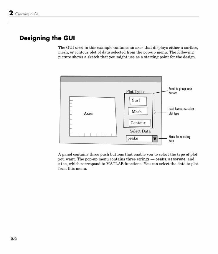
Designing the GUIThe GUI used in this example contains an axes that displays either a surface, mesh, or contour plot of data selected from the pop-up menu. The following picture shows a sketch that you might use as a starting point for the design.
A panel contains three push buttons that enable you to select the type of plot you want. The pop-up menu contains three strings — peaks, membrane, and sinc, which correspond to MATLAB functions. You can select the data to plot from this menu.
Select Data
peaks
Contour
Mesh
Surf
AxesPush buttons to select plot type
Menu for selecting data
Plot TypesPanel to group push buttons
Laying Out the GUI
2-3
Laying Out the GUIThis section illustrates how to lay out GUI components (i.e., a panel, axes, and user interface controls, such as push buttons, pop-up menus, static text, etc.) in the GUI. We recommend that you create the GUI for yourself, as this is the best way to learn how to use GUIDE.
The section explains how to
• “View Layout and Code for the Example” on page 2-3
• “Open a New GUI in the Layout Editor” on page 2-4
• “Set the GUI Figure Size” on page 2-6
• “Add the Components” on page 2-7
• “Align the Components” on page 2-9
View Layout and Code for the ExampleIf you are reading this in the MATLAB Help browser, you can click the following links to display the GUIDE Layout Editor and the MATLAB Editor with a completed version of this example. This enables you to see the values of all component properties and to understand how the components are assembled to create the GUI. You can also see a complete listing of the code that is discussed in the following sections.
Note The following links execute MATLAB commands and are designed to work within the MATLAB Help browser.
• Layout Editor with completed GUI layout
• MATLAB Editor with completed M-file. The M-file contains the code that controls the GUI.
An Animated Demo of Creating a GUIThe following link displays an animated version of this example.
Show GUIDE demonstration
2 Creating a GUI
2-4
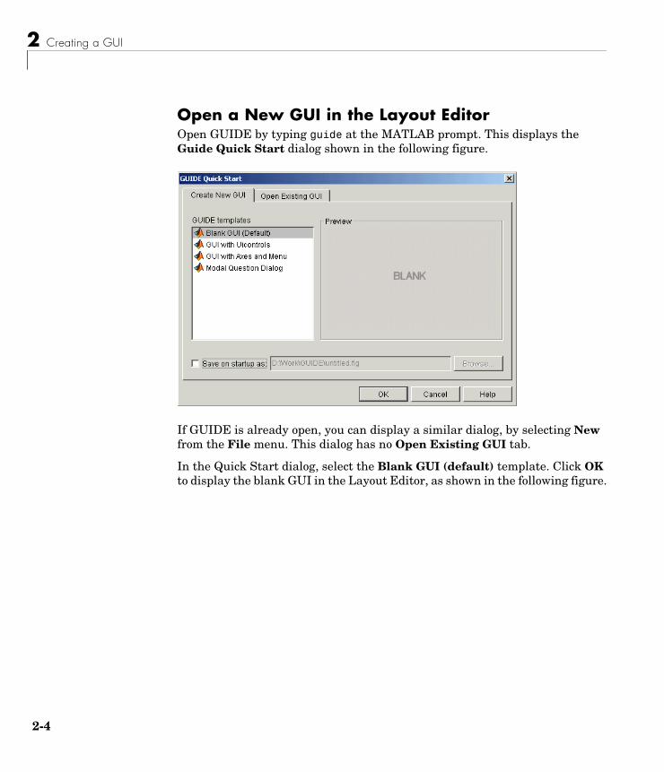
Open a New GUI in the Layout EditorOpen GUIDE by typing guide at the MATLAB prompt. This displays the Guide Quick Start dialog shown in the following figure.
If GUIDE is already open, you can display a similar dialog, by selecting New from the File menu. This dialog has no Open Existing GUI tab.
In the Quick Start dialog, select the Blank GUI (default) template. Click OK to display the blank GUI in the Layout Editor, as shown in the following figure.
Laying Out the GUI
2-5
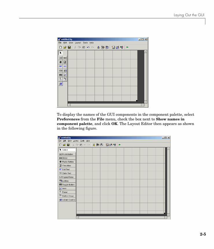
To display the names of the GUI components in the component palette, select Preferences from the File menu, check the box next to Show names in component palette, and click OK. The Layout Editor then appears as shown in the following figure.
2 Creating a GUI
2-6
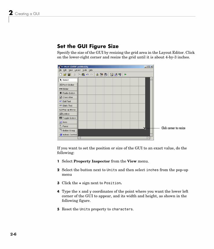
Set the GUI Figure SizeSpecify the size of the GUI by resizing the grid area in the Layout Editor. Click on the lower-right corner and resize the grid until it is about 4-by-3 inches.
If you want to set the position or size of the GUI to an exact value, do the following:
1 Select Property Inspector from the View menu.
2 Select the button next to Units and then select inches from the pop-up menu
3 Click the + sign next to Position.
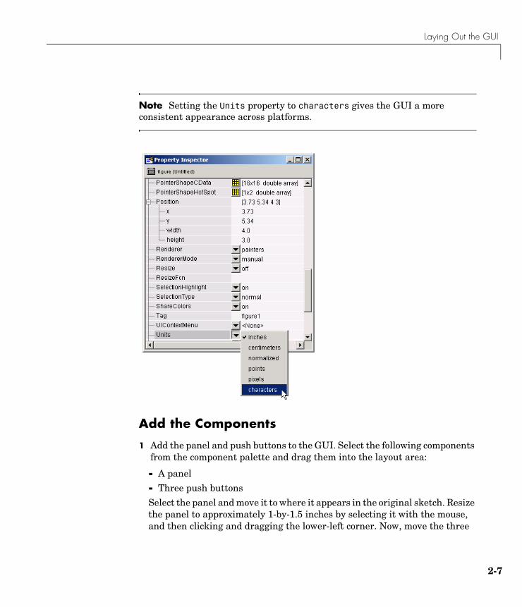
4 Type the x and y coordinates of the point where you want the lower left corner of the GUI to appear, and its width and height, as shown in the following figure.
5 Reset the Units property to characters.
Click corner to resize
Laying Out the GUI
2-7
Note Setting the Units property to characters gives the GUI a more consistent appearance across platforms.
Add the Components
1 Add the panel and push buttons to the GUI. Select the following components from the component palette and drag them into the layout area:
- A panel
- Three push buttons
Select the panel and move it to where it appears in the original sketch. Resize the panel to approximately 1-by-1.5 inches by selecting it with the mouse, and then clicking and dragging the lower-left corner. Now, move the three
2 Creating a GUI
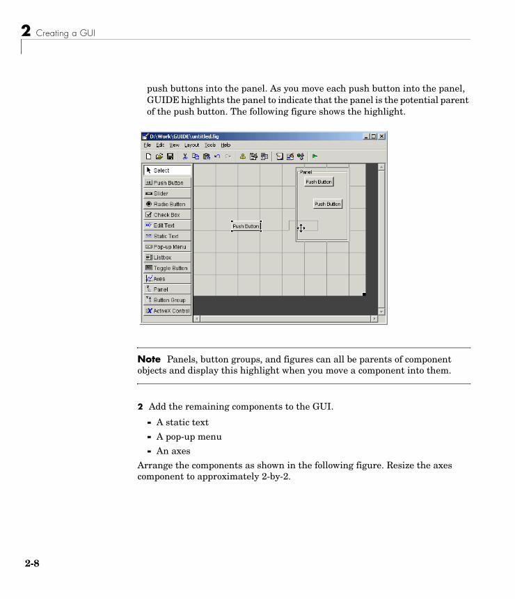
2-8
push buttons into the panel. As you move each push button into the panel, GUIDE highlights the panel to indicate that the panel is the potential parent of the push button. The following figure shows the highlight.
Note Panels, button groups, and figures can all be parents of component objects and display this highlight when you move a component into them.
2 Add the remaining components to the GUI.
- A static text
- A pop-up menu
- An axes
Arrange the components as shown in the following figure. Resize the axes component to approximately 2-by-2.
Laying Out the GUI
2-9
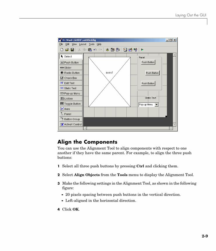
Align the ComponentsYou can use the Alignment Tool to align components with respect to one another if they have the same parent. For example, to align the three push buttons:
1 Select all three push buttons by pressing Ctrl and clicking them.
2 Select Align Objects from the Tools menu to display the Alignment Tool.
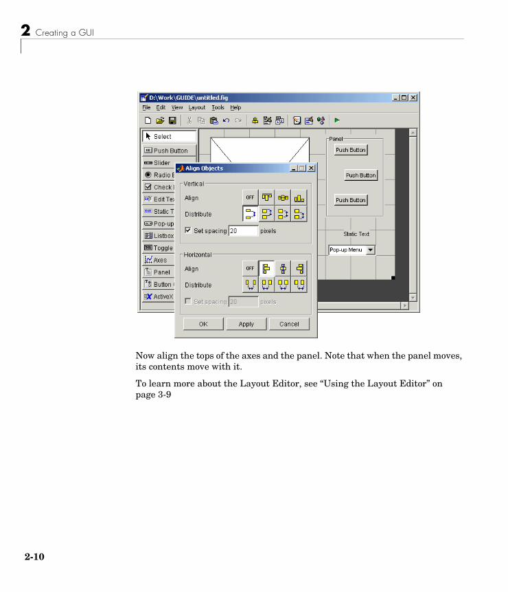
3 Make the following settings in the Alignment Tool, as shown in the following figure:
- 20 pixels spacing between push buttons in the vertical direction.
- Left-aligned in the horizontal direction.
4 Click OK.
2 Creating a GUI
2-10
Now align the tops of the axes and the panel. Note that when the panel moves, its contents move with it.
To learn more about the Layout Editor, see “Using the Layout Editor” on page 3-9
Setting Properties for GUI Components
2-11
Setting Properties for GUI ComponentsTo set the properties of each GUI component, select the Property Inspector from the View menu to display the Property Inspector dialog box. When you select a component in the Layout Editor, the Property Inspector displays that component’s properties. If no component is selected, the Property Inspector displays the properties of the GUI figure.
This section tells you how to set these properties:
• “Name Property” on page 2-11
• “Title Property” on page 2-12
• “String Property for Push Buttons and Static Text” on page 2-12
• “String Property for Pop-up Menus” on page 2-12
• “Callback Properties” on page 2-14
• “The Tag Property” on page 2-14
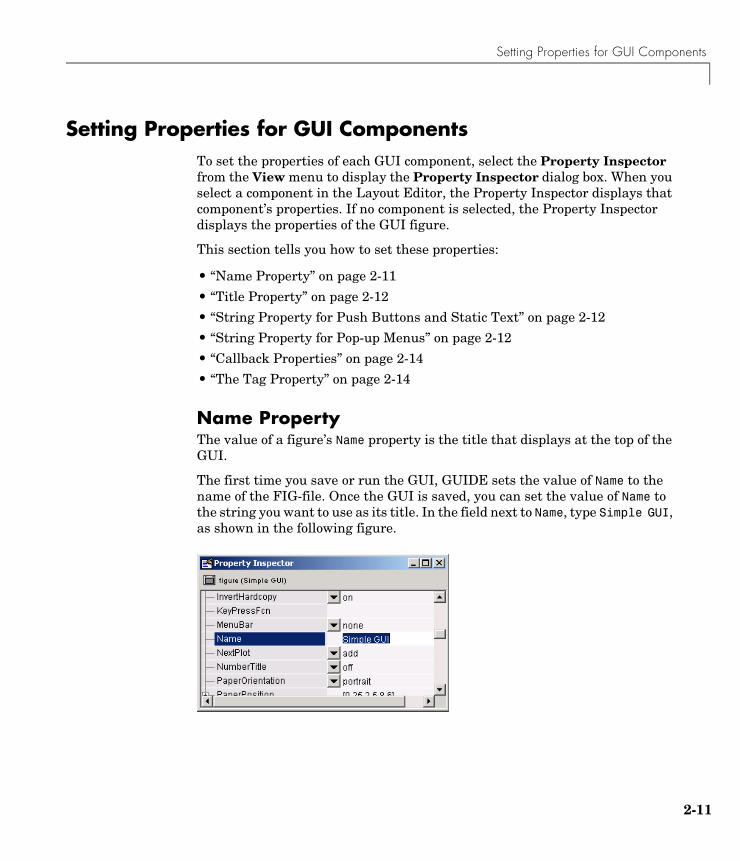
Name PropertyThe value of a figure’s Name property is the title that displays at the top of the GUI.
The first time you save or run the GUI, GUIDE sets the value of Name to the name of the FIG-file. Once the GUI is saved, you can set the value of Name to the string you want to use as its title. In the field next to Name, type Simple GUI, as shown in the following figure.
2 Creating a GUI
2-12
Title PropertyA panel’s Title property controls the title that appears at the top or bottom of the panel. Select the panel in the Layout Editor and then scroll down in the Property Inspector until you come to Title. In the field to the right of Title, change Panel to Plot Types. Use the TitlePosition property to control the position of the title.
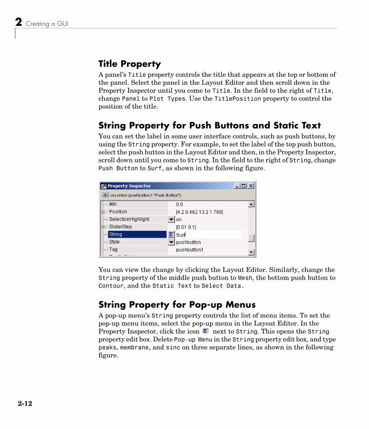
String Property for Push Buttons and Static TextYou can set the label in some user interface controls, such as push buttons, by using the String property. For example, to set the label of the top push button, select the push button in the Layout Editor and then, in the Property Inspector, scroll down until you come to String. In the field to the right of String, change Push Button to Surf, as shown in the following figure.
You can view the change by clicking the Layout Editor. Similarly, change the String property of the middle push button to Mesh, the bottom push button to Contour, and the Static Text to Select Data.
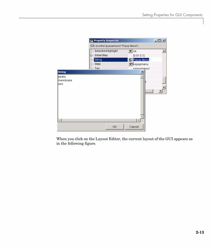
String Property for Pop-up MenusA pop-up menu’s String property controls the list of menu items. To set the pop-up menu items, select the pop-up menu in the Layout Editor. In the Property Inspector, click the icon next to String. This opens the String property edit box. Delete Pop-up Menu in the String property edit box, and type peaks, membrane, and sinc on three separate lines, as shown in the following figure.
Setting Properties for GUI Components
2-13
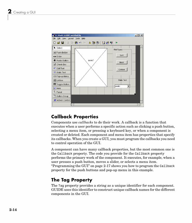
When you click on the Layout Editor, the current layout of the GUI appears as in the following figure.
2 Creating a GUI
2-14
Callback PropertiesComponents use callbacks to do their work. A callback is a function that executes when a user performs a specific action such as clicking a push button, selecting a menu item, or pressing a keyboard key, or when a component is created or deleted. Each component and menu item has properties that specify its callbacks. When you create a GUI, you must program the callbacks you need to control operation of the GUI.
A component can have many callback properties, but the most common one is the Callback property. The code you provide for the Callback property performs the primary work of the component. It executes, for example, when a user presses a push button, moves a slider, or selects a menu item. “Programming the GUI” on page 2-17 shows you how to program the Callback property for the push buttons and pop-up menu in this example.
The Tag PropertyThe Tag property provides a string as a unique identifier for each component. GUIDE uses this identifier to construct unique callback names for the different components in the GUI.
Setting Properties for GUI Components
2-15
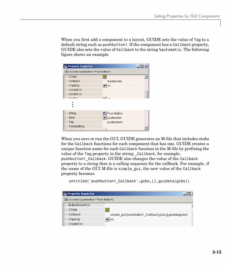
When you first add a component to a layout, GUIDE sets the value of Tag to a default string such as pushbutton1. If the component has a Callback property, GUIDE also sets the value of Callback to the string %automatic. The following figure shows an example.-
When you save or run the GUI, GUIDE generates an M-file that includes stubs for the Callback functions for each component that has one. GUIDE creates a unique function name for each Callback function in the M-file by prefixing the value of the Tag property to the string _Callback, for example, pushbutton1_Callback. GUIDE also changes the value of the Callback property to a string that is a calling sequence for the callback. For example, if the name of the GUI M-file is simple_gui, the new value of the Callback property becomes
untitled('pushbutton1_Callback',gcbo,[],guidata(gcbo))
...
2 Creating a GUI
2-16
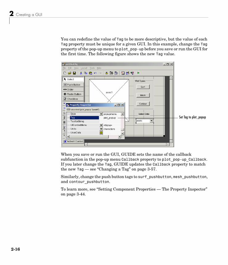
You can redefine the value of Tag to be more descriptive, but the value of each Tag property must be unique for a given GUI. In this example, change the Tag property of the pop-up menu to plot_pop-up before you save or run the GUI for the first time. The following figure shows the new Tag value.
When you save or run the GUI, GUIDE sets the name of the callback subfunction in the pop-up menu Callback property to plot_pop-up_Callback. If you later change the Tag, GUIDE updates the Callback property to match the new Tag — see “Changing a Tag” on page 3-57.
Similarly, change the push button tags to surf_pushbutton, mesh_pushbutton, and contour_pushbutton.
To learn more, see “Setting Component Properties — The Property Inspector” on page 3-44.
Set Tag to plot_popup
Programming the GUI
2-17
Programming the GUIAfter laying out the GUI and setting component properties, the next step is to program it. This section explains how to do that. The section covers
• “Creating the GUI M-File” on page 2-17
• “Opening the GUI M-File” on page 2-17
• “Sharing Data Between Callbacks” on page 2-19
• “Adding Code to the Opening Function” on page 2-20
• “Adding Code to the Callbacks” on page 2-22
• “Using the Object Browser to Identify Callbacks” on page 2-24
Creating the GUI M-FileWhen you first save or run the GUI, GUIDE generates a function M-file that contains the most commonly used callbacks for each component. It also contains some initialization code, an opening function callback, and an output function callback. Each callback is a subfunction that initially consists of a framework that contains just a function definition. You must add code to the callbacks to make them work.
You can save a GUI by selecting Save or Save as from the File menu, or by clicking the Save icon on the toolbar. You can run the GUI by selecting Run from the Tools menu or by clicking the Run icon on the toolbar.
After GUIDE generates the M-file, it opens the Save GUI as dialog. Type a name in the File name field. GUIDE assigns the same name to FIG-file and the M-file. When you click Save, GUIDE saves the M-file and opens it in the M-file Editor. If you are building the GUI in this example, use the filename simple_gui.
For more information, see “Understanding the GUI M-File” on page 4-2.
Opening the GUI M-FileIn this section you add code to the callbacks for the three push buttons and the pop-up menu.
Once GUIDE has created the M-file, you can open it in the MATLAB editor by clicking the M-file Editor icon on the toolbar. In the editor, you can move the
2 Creating a GUI
2-18
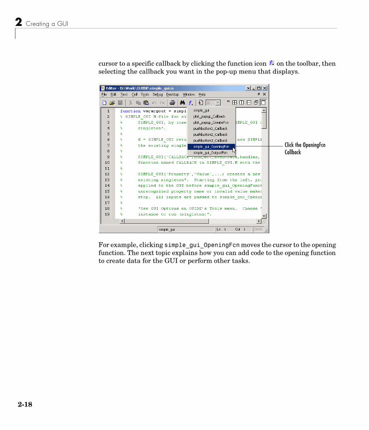
cursor to a specific callback by clicking the function icon on the toolbar, then selecting the callback you want in the pop-up menu that displays.
For example, clicking simple_gui_OpeningFcn moves the cursor to the opening function. The next topic explains how you can add code to the opening function to create data for the GUI or perform other tasks.
Click the OpeningFcn Callback
Programming the GUI
2-19
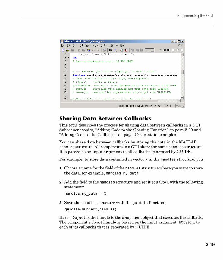
Sharing Data Between CallbacksThis topic describes the process for sharing data between callbacks in a GUI. Subsequent topics, “Adding Code to the Opening Function” on page 2-20 and “Adding Code to the Callbacks” on page 2-22, contain examples.
You can share data between callbacks by storing the data in the MATLAB handles structure. All components in a GUI share the same handles structure. It is passed as an input argument to all callbacks generated by GUIDE.
For example, to store data contained in vector X in the handles structure, you
1 Choose a name for the field of the handles structure where you want to store the data, for example, handles.my_data
2 Add the field to the handles structure and set it equal to X with the following statement:
handles.my_data = X;
3 Save the handles structure with the guidata function:
guidata(hObject,handles)
Here, hObject is the handle to the component object that executes the callback. The component’s object handle is passed as the input argument, hObject, to each of its callbacks that is generated by GUIDE.
2 Creating a GUI
2-20
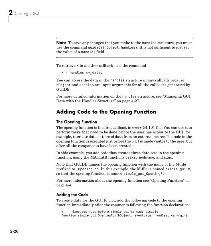
Note To save any changes that you make to the handles structure, you must use the command guidata(hObject,handles). It is not sufficient to just set the value of a handles field.
To retrieve X in another callback, use the command
X = handles.my_data;
You can access the data in the handles structure in any callback because hObject and handles are input arguments for all the callbacks generated by GUIDE.
For more detailed information on the handles structure, see “Managing GUI Data with the Handles Structure” on page 4-27.
Adding Code to the Opening Function
The Opening FunctionThe opening function is the first callback in every GUI M-file. You can use it to perform tasks that need to be done before the user has access to the GUI, for example, to create data or to read data from an external source.The code in the opening function is executed just before the GUI is made visible to the user, but after all the components have been created.
In this example, you add code that creates three data sets in the opening function, using the MATLAB functions peaks, membrane, and sinc.
Note that GUIDE names the opening function with the name of the M-file prefixed to _OpeningFcn. In this example, the M-file is named simple_gui.m, so that the opening function is named simple_gui_OpeningFcn.
For more information about the opening function see “Opening Function” on page 4-4.
Adding the CodeTo create data for the GUI to plot, add the following code to the opening function immediately after the comments following the function declaration.
% --- Executes just before simple_gui is made visible.function simple_gui_OpeningFcn(hObject, eventdata, handles, varargin)
Programming the GUI
2-21
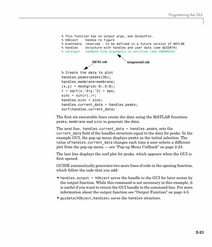
% This function has no output args, see OutputFcn.% hObject handle to figure% eventdata reserved - to be defined in a future version of MATLAB% handles structure with handles and user data (see GUIDATA)% varargin command line arguments to untitled (see VARARGIN)
% Create the data to plothandles.peaks=peaks(35);handles.membrane=membrane;[x,y] = meshgrid(-8:.5:8);r = sqrt(x.^2+y.^2) + eps;sinc = sin(r)./r;handles.sinc = sinc;handles.current_data = handles.peaks;surf(handles.current_data)
The first six executable lines create the data using the MATLAB functions peaks, membrane and sinc to generate the data.
The next line, handles.current_data = handles.peaks, sets the current_data field of the handles structure equal to the data for peaks. In the example GUI, the pop-up menu displays peaks as the initial selection. The value of handles.current_data changes each time a user selects a different plot from the pop-up menu — see “Pop-up Menu Callback” on page 2-24.
The last line displays the surf plot for peaks, which appears when the GUI is first opened.
GUIDE automatically generates two more lines of code in the opening function, which follow the code that you add:
• handles.output = hObject saves the handle to the GUI for later access by the output function. While this command is not necessary in this example, it is useful if you want to return the GUI handle to the command line. For more information about the output function see “Output Function” on page 4-5.
• guidata(hObject,handles) saves the handles structure.
Add this code Autogenerated code
2 Creating a GUI
2-22
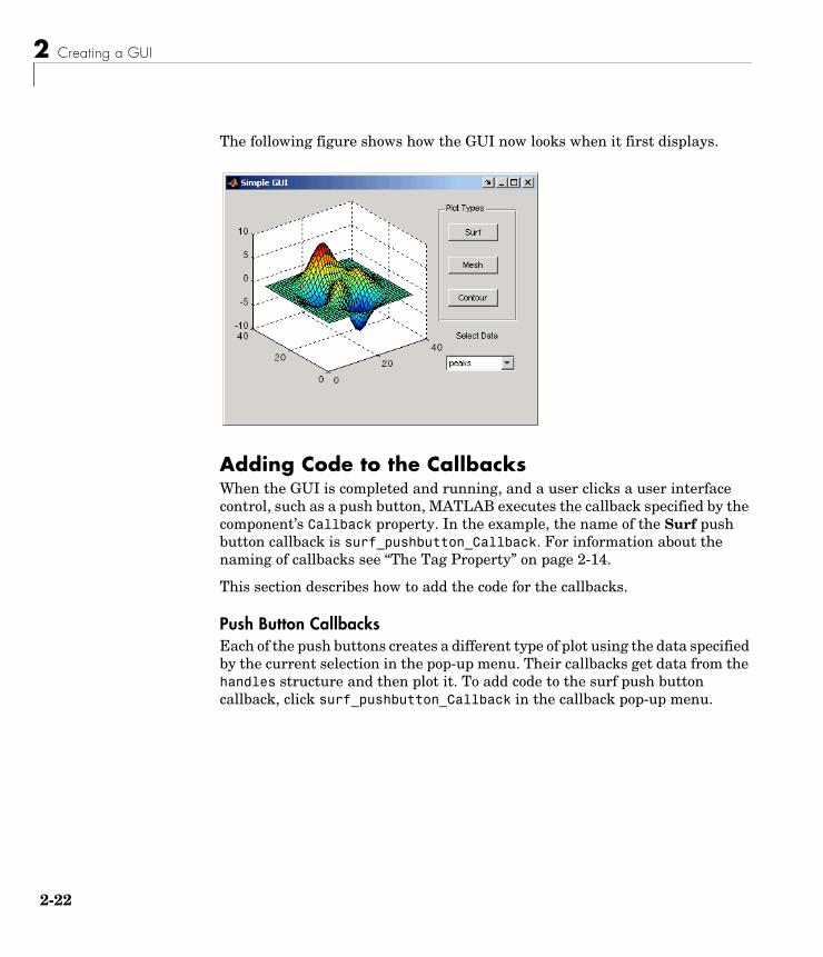
The following figure shows how the GUI now looks when it first displays.
Adding Code to the CallbacksWhen the GUI is completed and running, and a user clicks a user interface control, such as a push button, MATLAB executes the callback specified by the component’s Callback property. In the example, the name of the Surf push button callback is surf_pushbutton_Callback. For information about the naming of callbacks see “The Tag Property” on page 2-14.
This section describes how to add the code for the callbacks.
Push Button CallbacksEach of the push buttons creates a different type of plot using the data specified by the current selection in the pop-up menu. Their callbacks get data from the handles structure and then plot it. To add code to the surf push button callback, click surf_pushbutton_Callback in the callback pop-up menu.
Programming the GUI
2-23
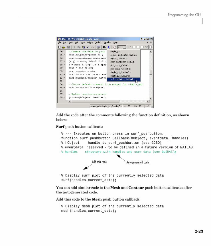
Add the code after the comments following the function definition, as shown below:
Surf push button callback:
% --- Executes on button press in surf_pushbutton.function surf_pushbutton_Callback(hObject, eventdata, handles)% hObject handle to surf_pushbutton (see GCBO)% eventdata reserved - to be defined in a future version of MATLAB% handles structure with handles and user data (see GUIDATA)
% Display surf plot of the currently selected datasurf(handles.current_data);
You can add similar code to the Mesh and Contour push button callbacks after the autogenerated code.
Add this code to the Mesh push button callback:
% Display mesh plot of the currently selected datamesh(handles.current_data);
Add this code Autogenerated code
2 Creating a GUI
2-24
Add this code to the Contour push button callback:
% Display contour plot of the currently selected datacontour(handles.current_data);
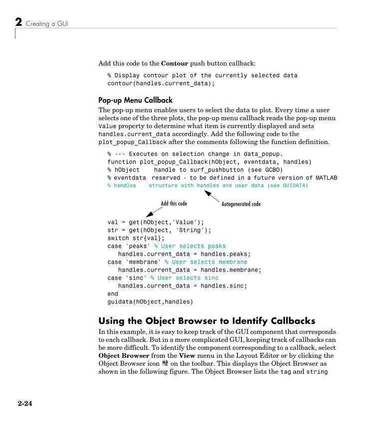
Pop-up Menu CallbackThe pop-up menu enables users to select the data to plot. Every time a user selects one of the three plots, the pop-up menu callback reads the pop-up menu Value property to determine what item is currently displayed and sets handles.current_data accordingly. Add the following code to the plot_popup_Callback after the comments following the function definition.
% --- Executes on selection change in data_popup.function plot_popup_Callback(hObject, eventdata, handles)% hObject handle to surf_pushbutton (see GCBO)% eventdata reserved - to be defined in a future version of MATLAB% handles structure with handles and user data (see GUIDATA)
val = get(hObject,'Value');str = get(hObject, 'String');switch str{val};case 'peaks' % User selects peaks handles.current_data = handles.peaks;case 'membrane' % User selects membrane handles.current_data = handles.membrane;case 'sinc' % User selects sinc handles.current_data = handles.sinc;endguidata(hObject,handles)
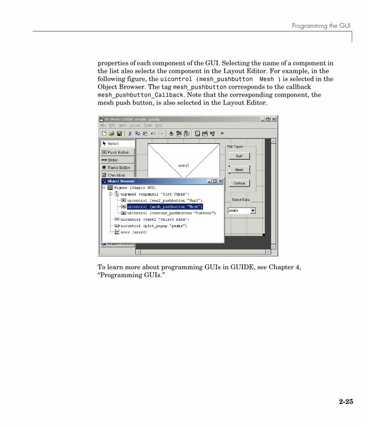
Using the Object Browser to Identify CallbacksIn this example, it is easy to keep track of the GUI component that corresponds to each callback. But in a more complicated GUI, keeping track of callbacks can be more difficult. To identify the component corresponding to a callback, select Object Browser from the View menu in the Layout Editor or by clicking the Object Browser icon on the toolbar. This displays the Object Browser as shown in the following figure. The Object Browser lists the tag and string
Add this code Autogenerated code
Programming the GUI
2-25
properties of each component of the GUI. Selecting the name of a component in the list also selects the component in the Layout Editor. For example, in the following figure, the uicontrol (mesh_pushbutton Mesh ) is selected in the Object Browser. The tag mesh_pushbutton corresponds to the callback mesh_pushbutton_Callback. Note that the corresponding component, the mesh push button, is also selected in the Layout Editor.
To learn more about programming GUIs in GUIDE, see Chapter 4, “Programming GUIs.”
2 Creating a GUI
2-26
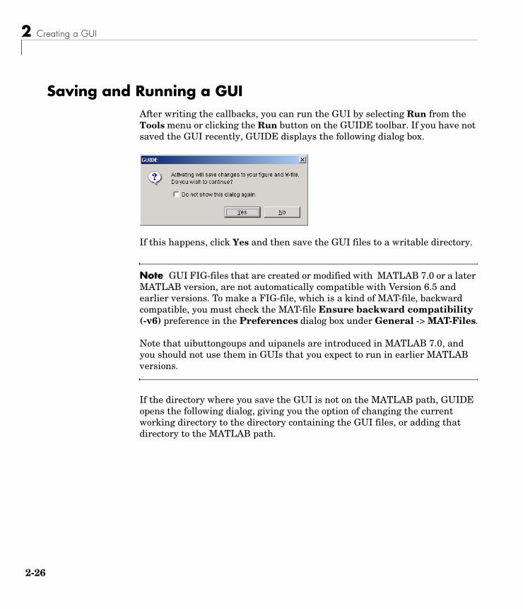
Saving and Running a GUIAfter writing the callbacks, you can run the GUI by selecting Run from the Tools menu or clicking the Run button on the GUIDE toolbar. If you have not saved the GUI recently, GUIDE displays the following dialog box.
If this happens, click Yes and then save the GUI files to a writable directory.
Note GUI FIG-files that are created or modified with MATLAB 7.0 or a later MATLAB version, are not automatically compatible with Version 6.5 and earlier versions. To make a FIG-file, which is a kind of MAT-file, backward compatible, you must check the MAT-file Ensure backward compatibility (-v6) preference in the Preferences dialog box under General -> MAT-Files.
Note that uibuttongoups and uipanels are introduced in MATLAB 7.0, and you should not use them in GUIs that you expect to run in earlier MATLAB versions.
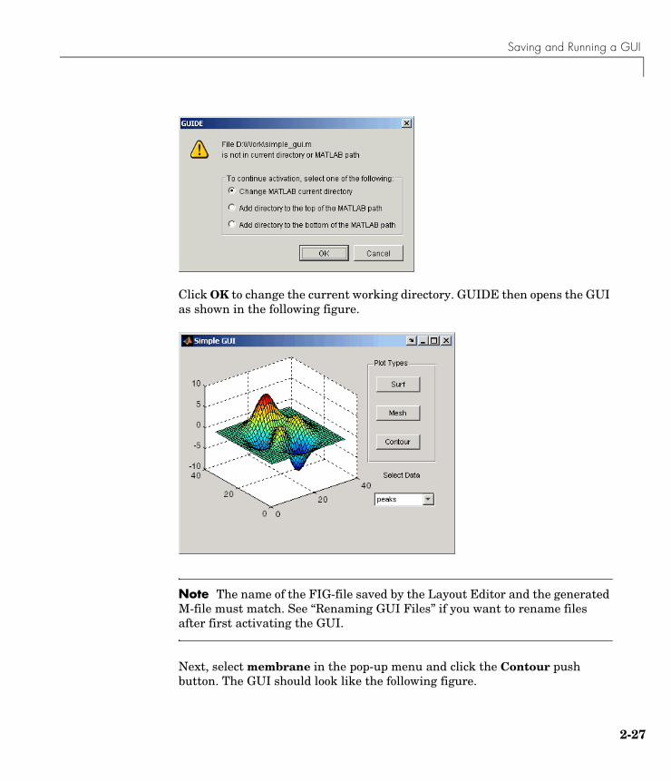
If the directory where you save the GUI is not on the MATLAB path, GUIDE opens the following dialog, giving you the option of changing the current working directory to the directory containing the GUI files, or adding that directory to the MATLAB path.
Saving and Running a GUI
2-27
Click OK to change the current working directory. GUIDE then opens the GUI as shown in the following figure.
Note The name of the FIG-file saved by the Layout Editor and the generated M-file must match. See “Renaming GUI Files” if you want to rename files after first activating the GUI.
Next, select membrane in the pop-up menu and click the Contour push button. The GUI should look like the following figure.

2 Creating a GUI
2-28
Try experimenting with this GUI by adding another data set in the opening function, and a push button that displays a plot of the data set. Make sure to add the name of the new data set to the pop-up menu as well.
For more examples of creating GUIs with GUIDE, see the following sections:
• “GUI Applications” on page 5-1
• “Using GUIDE Templates” on page 3-2
3Laying Out GUIs and Setting Properties
Using GUIDE Templates (p. 3-2) Overview of GUIDE templates — simple GUIs that you modify to create your own GUIs.
Using the Layout Editor (p. 3-9) Add and arrange objects in the figure window.
Selecting GUI Options (p. 3-29) Set the options for your GUI.
Aligning Components in the Layout Editor (p. 3-38)
Align objects with respect to each other.
Setting Component Properties — The Property Inspector (p. 3-44)
Inspect and set the property values of the GUI components.
Viewing the Object Hierarchy — The Object Browser (p. 3-60)
Observe a hierarchical list of the Handle Graphics® objects in the current MATLAB session.
Creating Menus — The Menu Editor (p. 3-61)
Create menus for the window menu bar and context menus for any component in your layout.
Setting the Tab Order (p. 3-73) Change the order in which GUI components are selected by tabbing.
3 Laying Out GUIs and Setting Properties
3-2
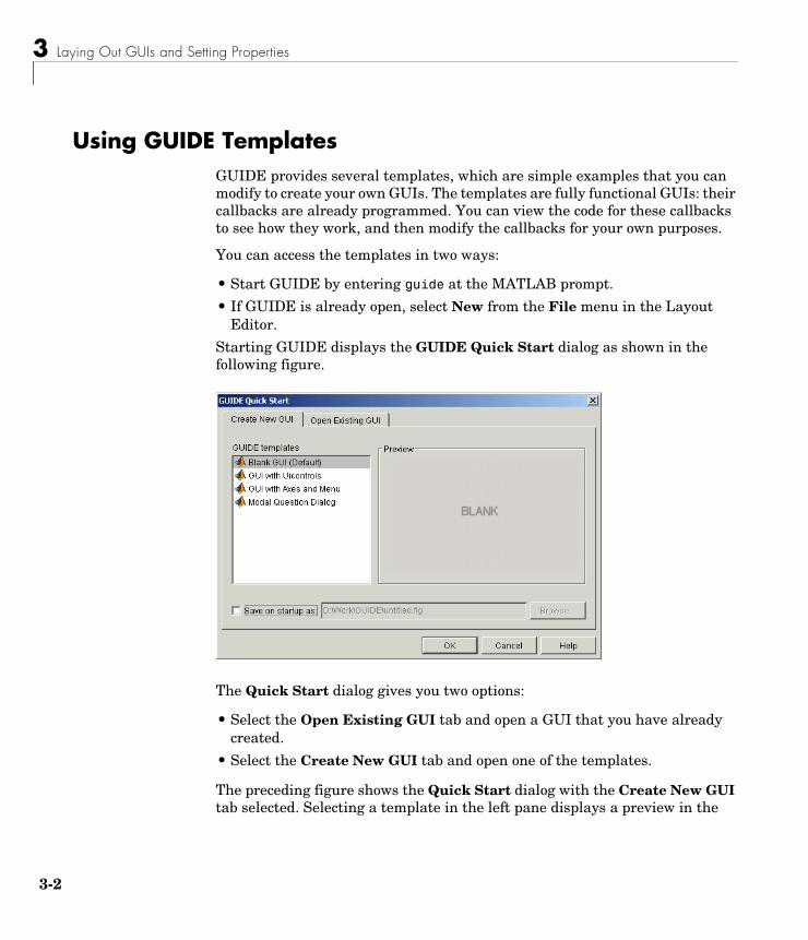
Using GUIDE TemplatesGUIDE provides several templates, which are simple examples that you can modify to create your own GUIs. The templates are fully functional GUIs: their callbacks are already programmed. You can view the code for these callbacks to see how they work, and then modify the callbacks for your own purposes.
You can access the templates in two ways:
• Start GUIDE by entering guide at the MATLAB prompt.
• If GUIDE is already open, select New from the File menu in the Layout Editor.
Starting GUIDE displays the GUIDE Quick Start dialog as shown in the following figure.
The Quick Start dialog gives you two options:
• Select the Open Existing GUI tab and open a GUI that you have already created.
• Select the Create New GUI tab and open one of the templates.
The preceding figure shows the Quick Start dialog with the Create New GUI tab selected. Selecting a template in the left pane displays a preview in the
Using GUIDE Templates
3-3
right pane. Clicking OK opens the GUI template in the Layout Editor. If you select Save on startup as and type in name in the field to the right, GUIDE saves the GUI before opening it in the Layout Editor. If you choose not to save the GUI at this point, GUIDE prompts you to save it the first time you run the GUI.
GUIDE provides four templates, which are described in the following sections:
• “Blank GUI” on page 3-3
• “GUI with Uicontrols” on page 3-4
• “GUI with Axes and Menu” on page 3-5
• “Modal Question Dialog” on page 3-6
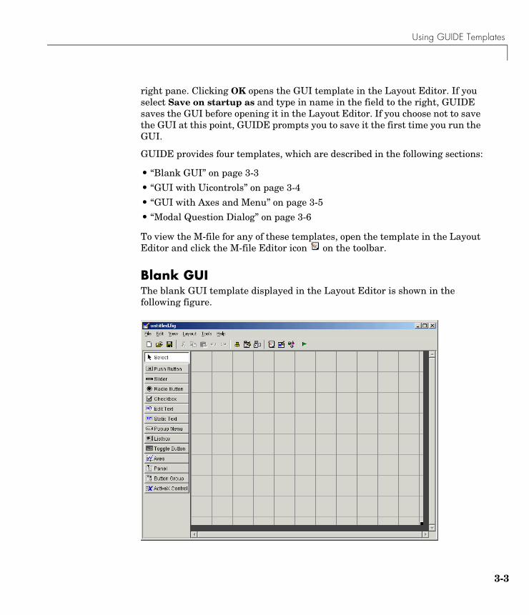
To view the M-file for any of these templates, open the template in the Layout Editor and click the M-file Editor icon on the toolbar.
Blank GUIThe blank GUI template displayed in the Layout Editor is shown in the following figure.
3 Laying Out GUIs and Setting Properties
3-4
Select the blank GUI if the other templates are not suitable starting points for the GUI you are creating, or if you prefer to start with an empty GUI.
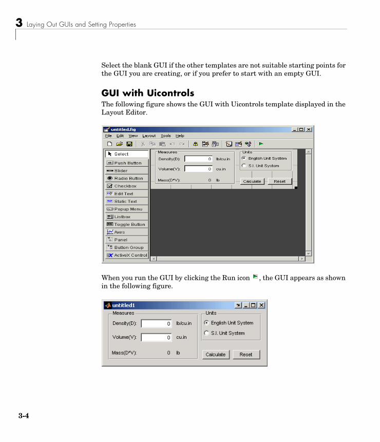
GUI with UicontrolsThe following figure shows the GUI with Uicontrols template displayed in the Layout Editor.
When you run the GUI by clicking the Run icon , the GUI appears as shown in the following figure.
Using GUIDE Templates
3-5
When a user enters values for the density and volume of an object, and clicks the Calculate button, the GUI calculates the mass of the object and displays the result next to Mass(D*V).
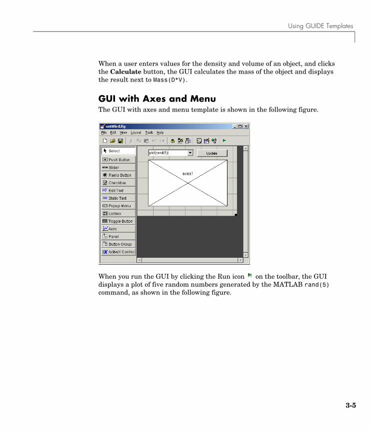
GUI with Axes and MenuThe GUI with axes and menu template is shown in the following figure.
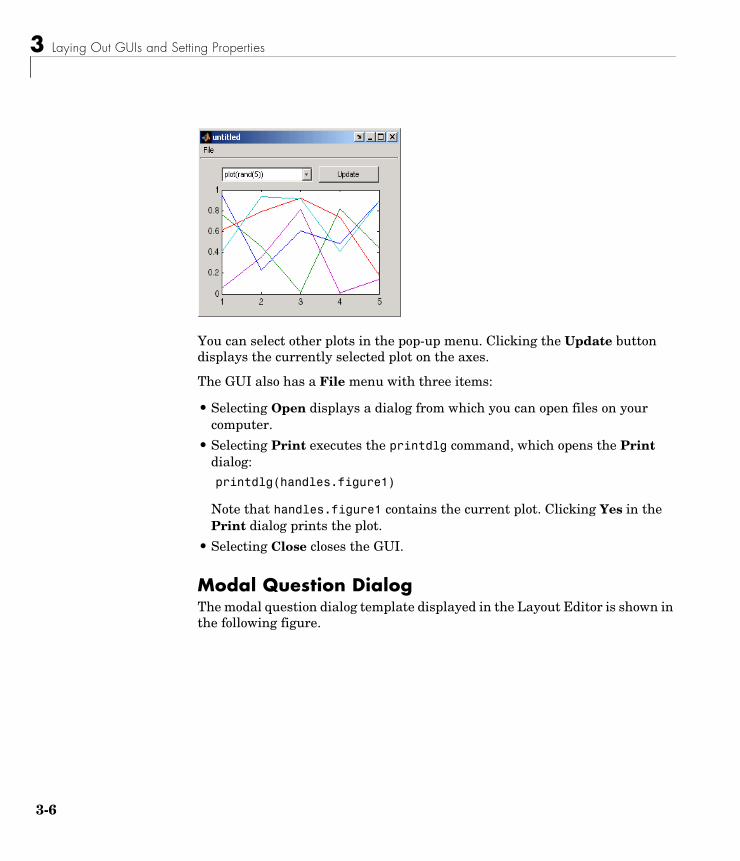
When you run the GUI by clicking the Run icon on the toolbar, the GUI displays a plot of five random numbers generated by the MATLAB rand(5) command, as shown in the following figure.
3 Laying Out GUIs and Setting Properties
3-6
You can select other plots in the pop-up menu. Clicking the Update button displays the currently selected plot on the axes.
The GUI also has a File menu with three items:
• Selecting Open displays a dialog from which you can open files on your computer.
• Selecting Print executes the printdlg command, which opens the Print dialog:printdlg(handles.figure1)
Note that handles.figure1 contains the current plot. Clicking Yes in the Print dialog prints the plot.
• Selecting Close closes the GUI.
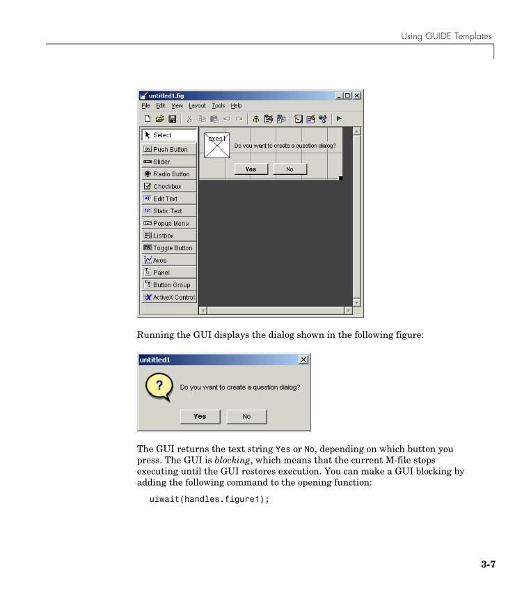
Modal Question DialogThe modal question dialog template displayed in the Layout Editor is shown in the following figure.
Using GUIDE Templates
3-7
Running the GUI displays the dialog shown in the following figure:
The GUI returns the text string Yes or No, depending on which button you press. The GUI is blocking, which means that the current M-file stops executing until the GUI restores execution. You can make a GUI blocking by adding the following command to the opening function:
uiwait(handles.figure1);
3 Laying Out GUIs and Setting Properties
3-8
To restore access to other MATLAB windows once a button is clicked, add the following command to callbacks for both the Yes and No push buttons:
uiresume(handles.figure1);
The GUI is also modal, which means that the user cannot interact with other MATLAB windows until clicking one of the buttons. See “Using Modal Figure Windows” on page 4-40 for more information on making a GUI modal.
Select this template if you want your GUI to return a string or to be modal.
See “Example: Using the Modal Dialog to Confirm an Operation” on page 4-42 for an example of using this template with another GUI.
Using the Layout Editor
3-9
Using the Layout EditorThe Layout Editor enables you to select GUI components from the component palette, at the left side of Layout Editor, and arrange them in the layout area, to the right. When you click the run icon , the functioning GUI appears outside the Layout Editor.
This section covers the following topics:
• “Starting the Layout Editor” on page 3-9
• “Selecting Components from the Component Palette” on page 3-10
• “Adding Components to the Layout Area” on page 3-13
• “Working with Components in the Layout Area” on page 3-16
• “Running the GUI” on page 3-19
• “Saving the Layout” on page 3-21
• “Renaming GUI Files” on page 3-21
• “Displaying the GUI” on page 3-22
• “Layout Editor Preferences” on page 3-22
• “Layout Editor Context Menus” on page 3-27
Starting the Layout EditorTo start the Layout Editor, first open the GUIDE Quick Start dialog by entering guide at the MATLAB prompt. Click OK in the dialog to open a blank GUI template in the Layout Editor, as shown in the following picture.
3 Laying Out GUIs and Setting Properties
3-10
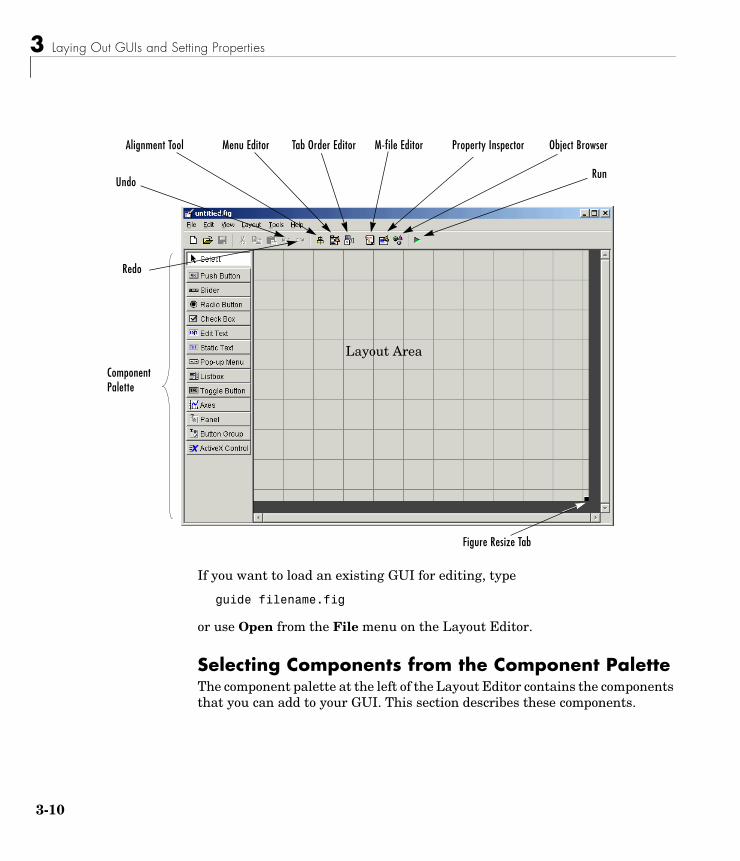
If you want to load an existing GUI for editing, type
guide filename.fig
or use Open from the File menu on the Layout Editor.
Selecting Components from the Component PaletteThe component palette at the left of the Layout Editor contains the components that you can add to your GUI. This section describes these components.
Component Palette
Alignment Tool Menu Editor Property Inspector
Run
Layout Area
Figure Resize Tab
Undo
Redo
Object BrowserM-file EditorTab Order Editor
Using the Layout Editor
3-11
After selecting the components for your GUI and placing them in the layout area, you need to set their properties and program their callbacks. The following sections describe how to do this:
• “Setting Component Properties — The Property Inspector” on page 3-44
• “Programming Callbacks for GUI Components” on page 4-8
Push ButtonPush buttons generate an action when clicked. For example, an OK button might close a dialog box and apply settings. When you click a push button, it appears depressed; when you release the mouse, the button appears raised and its callback executes.
Toggle ButtonToggle buttons generate an action and indicate whether they are turned on or off. When you click a toggle button, it appears depressed, showing that it is on. When you release the mouse button, the toggle button’s callback executes. However, unlike a push button, the toggle button remains depressed until you click the toggle button a second time. When you do so, the button returns to the raised state, showing that it is off, and again executes its callback.
Radio ButtonRadio buttons are similar to check boxes, but are typically mutually exclusive within a group of related radio buttons. That is, you can select only one button at any given time. To activate a radio button, click the mouse button on the object. The display indicates the state of the button.
Check BoxCheck boxes generate an action when checked and indicate their state as checked or not checked. Check boxes are useful when providing the user with a number of independent choices that set a mode, for example, displaying a toolbar or generating callback function prototypes.
Edit TextEdit text controls are fields that enable users to enter or modify text strings. Use edit text when you want text as input. The String property contains the text entered by the user. The callback executes when you press Enter for a
3 Laying Out GUIs and Setting Properties
3-12
single-line edit text, Ctl+Enter for a multi-line edit text, or the focus moves away.
Static TextStatic text controls display lines of text. Static text is typically used to label other controls, provide directions to the user, or indicate values associated with a slider. Users cannot change static text interactively and there is no way to invoke the callback routine associated with it.
SliderSliders accept numeric input within a specific range by enabling the user to move a sliding bar, which is called a slider or thumb. Users move the slider by pressing the mouse button and dragging the slider, by clicking in the trough, or by clicking an arrow. The location of the slider indicates a percentage of the specified range.
List BoxList boxes display a list of items and enable users to select one or more items.
Pop-Up MenuPop-up menus open to display a list of choices when users click the arrow.
AxesAxes enable your GUI to display graphics (e.g., graphs and images). Like all graphics objects, axes have properties that you can set to control many aspects of its behavior and appearance. See “Axes Properties” in the MATLAB Graphics documentation for more information on axes objects.
PanelPanels group GUI components. Panels can make a user interface easier to understand by visually grouping related controls. A panel can have a title and various borders.
Panel children can be panels and button groups as well as axes and user interface controls. The position of each component within a panel is interpreted relative to the panel. If you move the panel, its children move with it and maintain their positions on the panel.
Using the Layout Editor
3-13
Button GroupButton groups are like panels but can be used to manage exclusive selection behavior for radio buttons and toggle buttons.
For radio buttons and toggle buttons that are managed by a button group, you must include the code to control them in the button group’s SelectionChangeFcn callback function, not in the individual uicontrol Callback functions. A button group overwrites the Callback properties of radio buttons and toggle buttons that it manages.
ActiveX ComponentActiveX components enable you to display ActiveX controls in your GUI. See “Adding an ActiveX Control to a GUI” on page 4-17 for more information and an example.
Note Only figures can have child ActiveX components. Panels and button groups cannot.
ActiveX components are available only on the Microsoft Windows platform.
Adding Components to the Layout AreaYou can place a component in the layout area in one of these ways:
• Drag the component from the component palette into the layout area and drop it.
• Select the component in the component palette. The cursor changes to a cross.
- Place the cursor in the layout area where you want the upper-left corner of the component to be and click.
- Place the cursor in the layout area where you want the upper-left corner of the component to be, then set the size of the control by clicking and dragging the cursor to the lower-left corner before releasing the mouse button.
3 Laying Out GUIs and Setting Properties
3-14
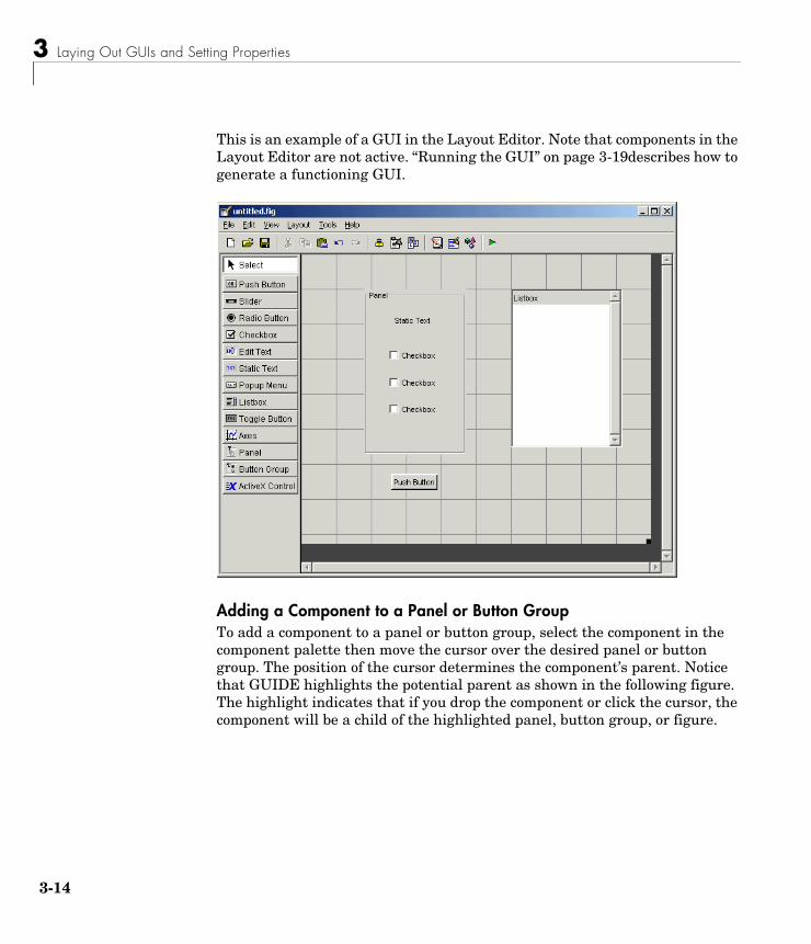
This is an example of a GUI in the Layout Editor. Note that components in the Layout Editor are not active. “Running the GUI” on page 3-19describes how to generate a functioning GUI.
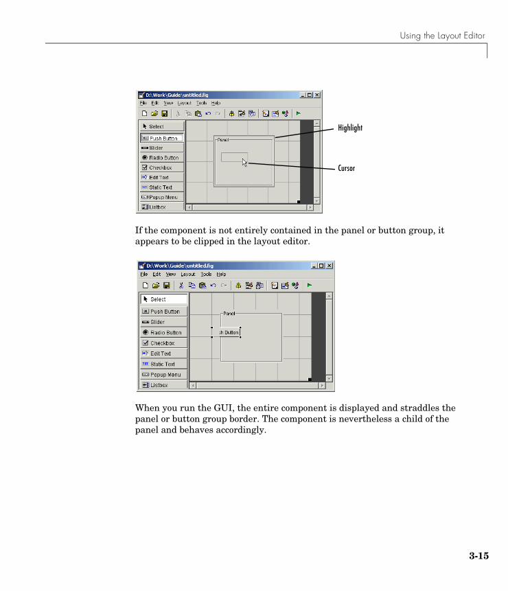
Adding a Component to a Panel or Button GroupTo add a component to a panel or button group, select the component in the component palette then move the cursor over the desired panel or button group. The position of the cursor determines the component’s parent. Notice that GUIDE highlights the potential parent as shown in the following figure. The highlight indicates that if you drop the component or click the cursor, the component will be a child of the highlighted panel, button group, or figure.
Using the Layout Editor
3-15
If the component is not entirely contained in the panel or button group, it appears to be clipped in the layout editor.
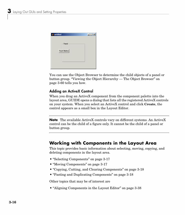
When you run the GUI, the entire component is displayed and straddles the panel or button group border. The component is nevertheless a child of the panel and behaves accordingly.
Highlight
Cursor
3 Laying Out GUIs and Setting Properties
3-16
You can use the Object Browser to determine the child objects of a panel or button group. “Viewing the Object Hierarchy — The Object Browser” on page 3-60 tells you how.
Adding an ActiveX ControlWhen you drag an ActiveX component from the component palette into the layout area, GUIDE opens a dialog that lists all the registered ActiveX controls on your system. When you select an ActiveX control and click Create, the control appears as a small box in the Layout Editor.
Note The available ActiveX controls vary on different systems. An ActiveX control can be the child of a figure only. It cannot be the child of a panel or button group.
Working with Components in the Layout AreaThis topic provides basic information about selecting, moving, copying, and deleting components in the layout area.
• “Selecting Components” on page 3-17
• “Moving Components” on page 3-17
• “Copying, Cutting, and Clearing Components” on page 3-18
• “Pasting and Duplicating Components” on page 3-18
Other topics that may be of interest are
• “Aligning Components in the Layout Editor” on page 3-38
Using the Layout Editor
3-17
• “Front-to-Back Positioning” on page 3-42
• “Setting the Tab Order” on page 3-73
Selecting ComponentsYou can select components in the layout area in the following ways.
• Click a single component to select it.
• Press Ctrl+A to select all child objects of the figure. This does not select components that are child objects of panels or button groups.
• Click and drag the cursor to create a rectangle that encloses the components you want to select. If the rectangle encloses a panel or button group, only the panel or button group is selected, not its children. If the rectangle encloses part of a panel or button group, only the components within the rectangle that are child objects of the panel or button group are selected.
• Select multiple components using the Shift and Ctrl keys.
Note You can select multiple components only if they have the same parent. Use the Object Browser to determine the child objects of a figure, panel, or button group. “Viewing the Object Hierarchy — The Object Browser” on page 3-60 tells you how.
Moving ComponentsSelect one or more components that you want to move, then do one of the following:
• Drag the selected components to the desired position and drop them. You can move components from the figure into a panel or button group. You can move components from a panel or button group into the figure or into another panel or button group.
The position of the cursor when you drop the components determines the parent of all the selected components. Look for the highlight as described in “Adding a Component to a Panel or Button Group” on page 3-14.
In some cases, one or more of the selected components may lie outside its parent’s boundary. Such a component is not visible in the Layout Editor but
3 Laying Out GUIs and Setting Properties
3-18
can be selected by dragging a rectangle that encloses it. It is visible, however, in the active GUI.
• Press and hold the arrow keys until the components have moved to the desired position. Note that the components remain children of the figure, panel, or button group from which you move them, even if they move outside its boundaries.
Copying, Cutting, and Clearing ComponentsUse standard menu and pop-up menu commands, toolbar icons, keyboard keys, and shortcut keys to copy, cut, and clear components.
Copying. Copying places a copy of the selected components on the clipboard. A copy of a panel or button group includes its children.
Cutting. Cutting places a copy of the selected components on the clipboard and deletes them from the layout area. If you cut a panel or button group, you also cut all its children.
Clearing. Clearing deletes the selected components from the layout area. It does not place a copy of the components on the clipboard.
Pasting and Duplicating Components
Pasting. Use standard menu and pop-up menu commands, toolbar icons, and short-cut keys to paste components. GUIDE pastes the contents of the clipboard to the location of the last mouse click. It positions the upper left corner of the contents at the mouse click
Consecutive pastes place each copy to the lower right of the last one.
Duplicating. Select one or more components that you want to duplicate, then do one of the following:
• Copy and paste the selected components as described above.
• Select Duplicate from the Edit menu or the pop-up menu. Duplicate places the copy to the lower right of the original.
• Right-click and drag the component to the desired location. The position of the cursor when you drop the components determines the parent of all the
Using the Layout Editor
3-19
selected components. Look for the highlight as described in “Adding a Component to a Panel or Button Group” on page 3-14.
Running the GUITo run the GUI you design in the Layout Editor, select Run in the Tools menu or click the Run icon on the toolbar.
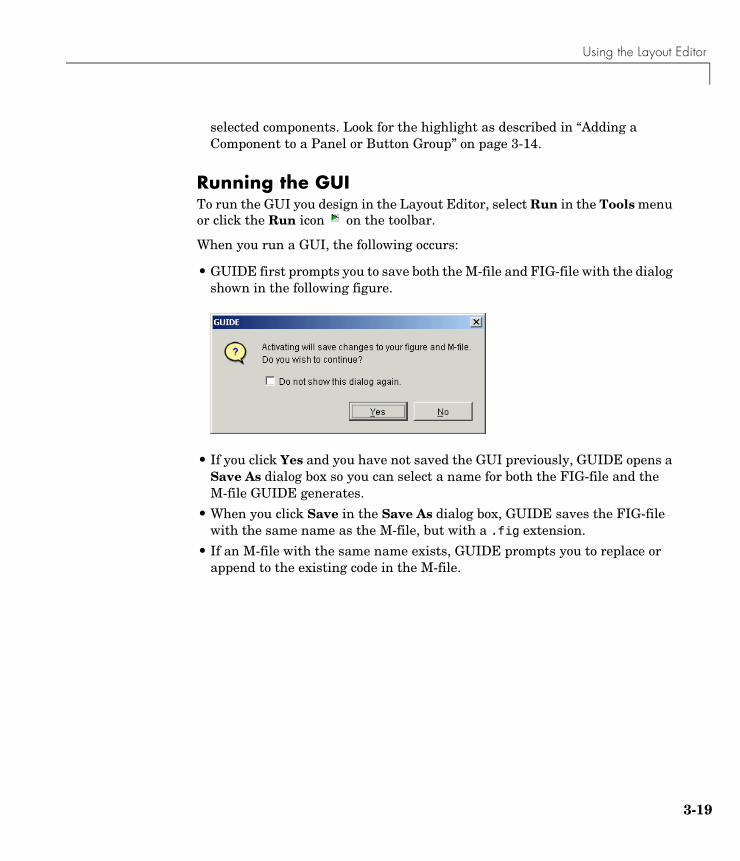
When you run a GUI, the following occurs:
• GUIDE first prompts you to save both the M-file and FIG-file with the dialog shown in the following figure.
• If you click Yes and you have not saved the GUI previously, GUIDE opens a Save As dialog box so you can select a name for both the FIG-file and the M-file GUIDE generates.
• When you click Save in the Save As dialog box, GUIDE saves the FIG-file with the same name as the M-file, but with a .fig extension.
• If an M-file with the same name exists, GUIDE prompts you to replace or append to the existing code in the M-file.
3 Laying Out GUIs and Setting Properties
3-20
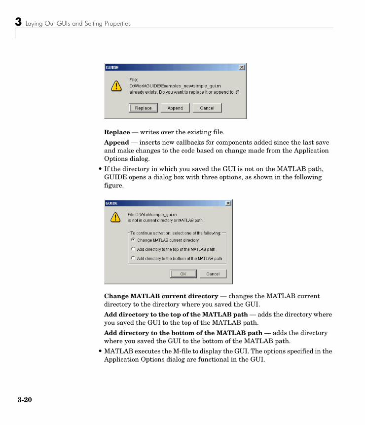
Replace — writes over the existing file.
Append — inserts new callbacks for components added since the last save and make changes to the code based on change made from the Application Options dialog.
• If the directory in which you saved the GUI is not on the MATLAB path, GUIDE opens a dialog box with three options, as shown in the following figure.
Change MATLAB current directory — changes the MATLAB current directory to the directory where you saved the GUI.
Add directory to the top of the MATLAB path — adds the directory where you saved the GUI to the top of the MATLAB path.
Add directory to the bottom of the MATLAB path — adds the directory where you saved the GUI to the bottom of the MATLAB path.
• MATLAB executes the M-file to display the GUI. The options specified in the Application Options dialog are functional in the GUI.
Using the Layout Editor
3-21
Note GUIDE automatically saves both the M-file and the FIG-file when you run the GUI.
Saving the LayoutOnce you have created the GUI layout, you can save it as a FIG-file (a binary file that saves the contents of a figure) using the Save or Save As item from the File menu. GUIDE generates the M-file automatically when you save or run the figure.
Note GUI FIG-files that are created or modified with MATLAB 7.0 or a later MATLAB version, are not automatically compatible with Version 6.5 and earlier versions. To make a FIG-file, a kind of MAT-file, backward compatible, you must check the MAT-file Ensure backward compatibility (-v6) preference in the Preferences dialog box under General -> MAT-Files.
Renaming GUI FilesUse Save As from the Layout Editor File menu to rename the GUI FIG-file. GUIDE renames the FIG-file and the GUI M-file and also resets the callback properties to properly execute the callbacks.
Exporting a GUI to a Single M-FileYou can export a GUI from GUIDE to a single M-file that does not require a FIG-file. This enables you to
• View the layout code for the GUI
• Run the GUI in MATLAB 6.1
Note If the GUI contains a panel or a button group, you will not be able to run it in MATLAB versions earlier than 7.0.
3 Laying Out GUIs and Setting Properties
3-22
To export your GUI, do the following steps:
1 Save the GUI in GUIDE, if you have not already done so.
2 Select Export from the File menu. If you changed the GUI since you last saved it, this opens a dialog informing you that exporting will save changes to your figure and M-file, and asking if you want to continue.
3 Click OK in the confirmation dialog.
4 Save the exported M-file in the Save As dialog. By default, GUIDE gives the exported M-file the name of the GUI M-file with _export appended.
Note If you save a large data set in the GUI figure or in a uicontrol, GUIDE might also export a MAT-file containing the data in addition to exporting an M-file. For example, the data could be saved in a figure or uicontrol UserData property, or in a figure Colormap property. The name of the MAT-file is the same as the exported M-file except for the extension .mat.
Displaying the GUIYou can display the GUI figure using the openfig, open, or hgload command. These commands load FIG-files into the MATLAB workspace. Note that the displayed GUI is not active.
Generally, however, you launch your GUI by executing the M-file that GUIDE generates. This M-file contains the commands to load the GUI and provides a framework for the component callbacks. See “Configuring the GUI M-File” on page 3-29 for more information.
Layout Editor PreferencesYou can set preferences for the GUIDE Layout Editor by selecting Preferences from the File menu. The preferences are grouped in different locations:
• “Confirmation Preferences” on page 3-23
• “Backward Compatibility Preference” on page 3-24
• “All Other Preferences” on page 3-24
Using the Layout Editor
3-23
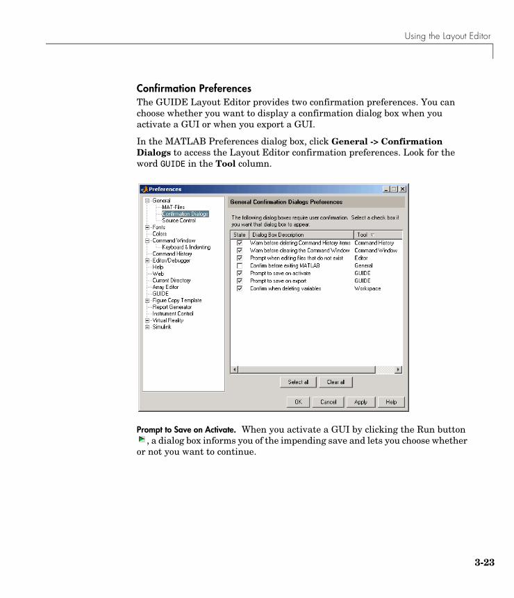
Confirmation PreferencesThe GUIDE Layout Editor provides two confirmation preferences. You can choose whether you want to display a confirmation dialog box when you activate a GUI or when you export a GUI.
In the MATLAB Preferences dialog box, click General -> Confirmation Dialogs to access the Layout Editor confirmation preferences. Look for the word GUIDE in the Tool column.
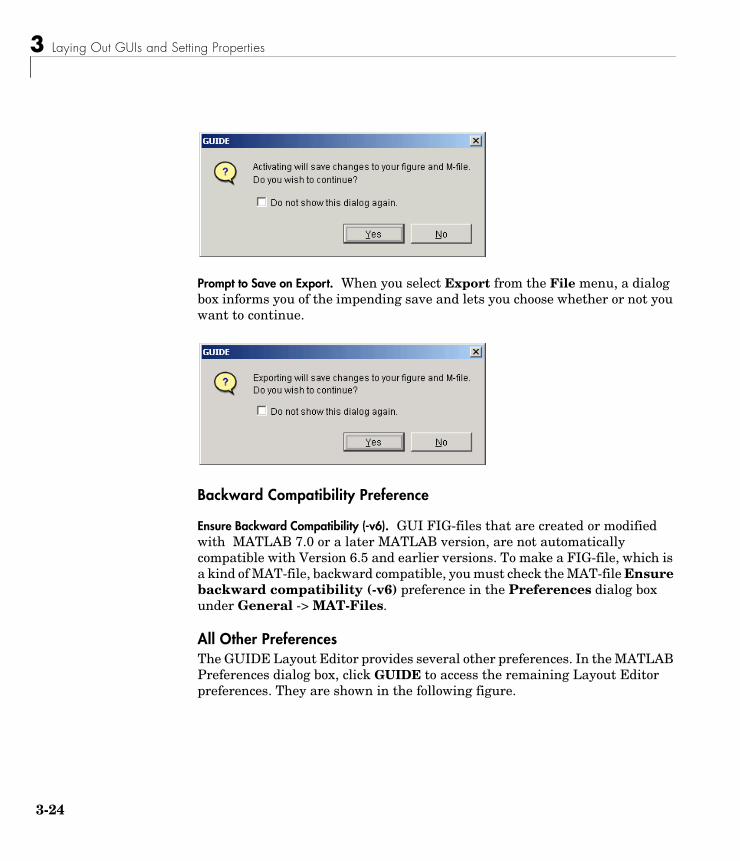
Prompt to Save on Activate. When you activate a GUI by clicking the Run button , a dialog box informs you of the impending save and lets you choose whether
or not you want to continue.
3 Laying Out GUIs and Setting Properties
3-24
Prompt to Save on Export. When you select Export from the File menu, a dialog box informs you of the impending save and lets you choose whether or not you want to continue.
Backward Compatibility Preference
Ensure Backward Compatibility (-v6). GUI FIG-files that are created or modified with MATLAB 7.0 or a later MATLAB version, are not automatically compatible with Version 6.5 and earlier versions. To make a FIG-file, which is a kind of MAT-file, backward compatible, you must check the MAT-file Ensure backward compatibility (-v6) preference in the Preferences dialog box under General -> MAT-Files.
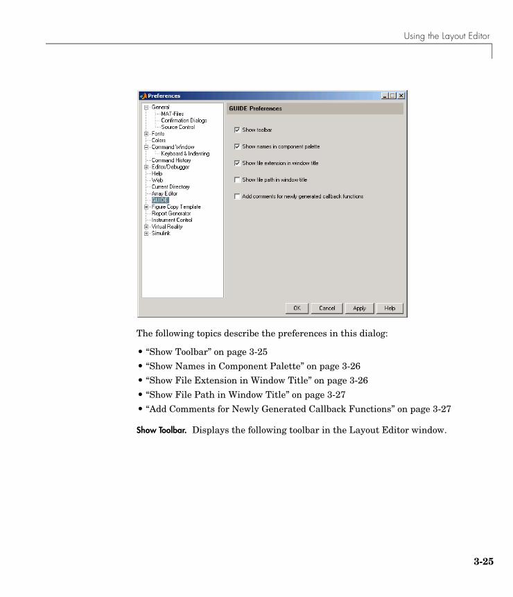
All Other PreferencesThe GUIDE Layout Editor provides several other preferences. In the MATLAB Preferences dialog box, click GUIDE to access the remaining Layout Editor preferences. They are shown in the following figure.
Using the Layout Editor
3-25
The following topics describe the preferences in this dialog:
• “Show Toolbar” on page 3-25
• “Show Names in Component Palette” on page 3-26
• “Show File Extension in Window Title” on page 3-26
• “Show File Path in Window Title” on page 3-27
• “Add Comments for Newly Generated Callback Functions” on page 3-27
Show Toolbar. Displays the following toolbar in the Layout Editor window.
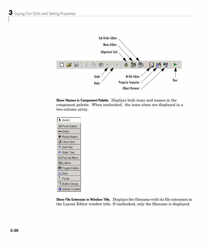
3 Laying Out GUIs and Setting Properties
3-26
Show Names in Component Palette. Displays both icons and names in the component palette. When unchecked, the icons alone are displayed in a two-column array.
Show File Extension in Window Title. Displays the filename with its file extension in the Layout Editor window title. If unchecked, only the filename is displayed.
Alignment Tool
Menu Editor
Property InspectorRun
Undo
RedoObject Browser
M-file Editor
Tab Order Editor
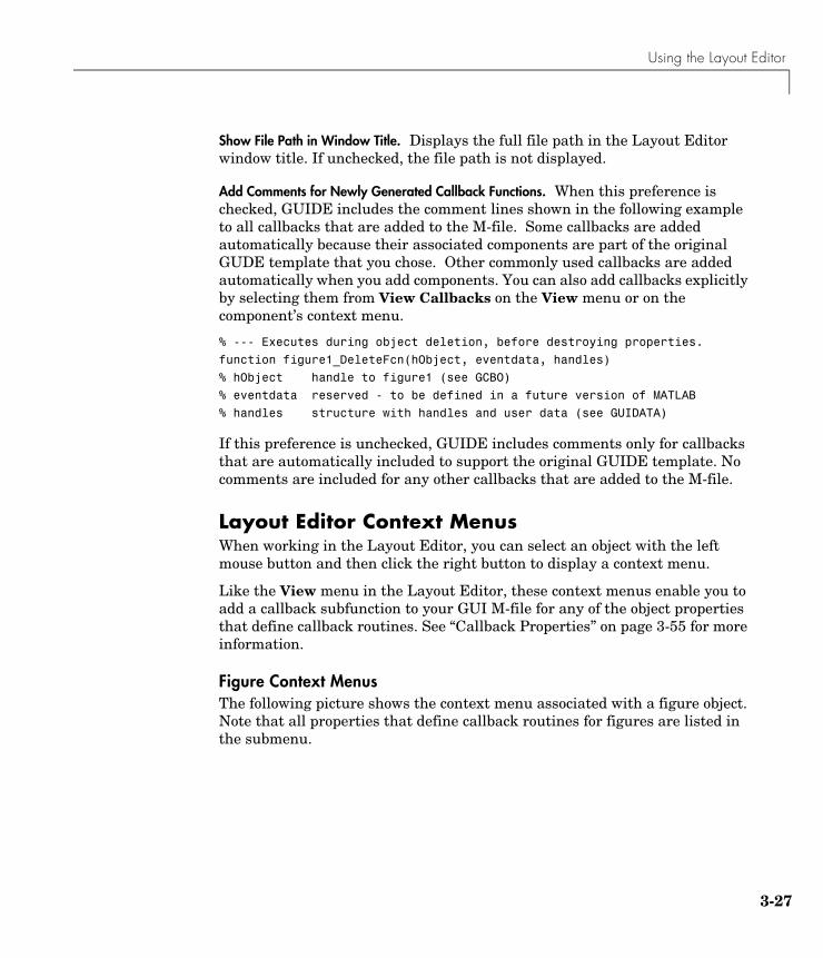
Using the Layout Editor
3-27
Show File Path in Window Title. Displays the full file path in the Layout Editor window title. If unchecked, the file path is not displayed.
Add Comments for Newly Generated Callback Functions. When this preference is checked, GUIDE includes the comment lines shown in the following example to all callbacks that are added to the M-file. Some callbacks are added automatically because their associated components are part of the original GUDE template that you chose. Other commonly used callbacks are added automatically when you add components. You can also add callbacks explicitly by selecting them from View Callbacks on the View menu or on the component’s context menu.
% --- Executes during object deletion, before destroying properties.
function figure1_DeleteFcn(hObject, eventdata, handles)
% hObject handle to figure1 (see GCBO)
% eventdata reserved - to be defined in a future version of MATLAB
% handles structure with handles and user data (see GUIDATA)
If this preference is unchecked, GUIDE includes comments only for callbacks that are automatically included to support the original GUIDE template. No comments are included for any other callbacks that are added to the M-file.
Layout Editor Context MenusWhen working in the Layout Editor, you can select an object with the left mouse button and then click the right button to display a context menu.
Like the View menu in the Layout Editor, these context menus enable you to add a callback subfunction to your GUI M-file for any of the object properties that define callback routines. See “Callback Properties” on page 3-55 for more information.
Figure Context MenusThe following picture shows the context menu associated with a figure object. Note that all properties that define callback routines for figures are listed in the submenu.
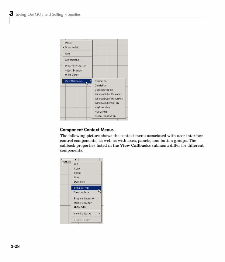
3 Laying Out GUIs and Setting Properties
3-28
Component Context MenusThe following picture shows the context menu associated with user interface control components, as well as with axes, panels, and button groups. The callback properties listed in the View Callbacks submenu differ for different components.
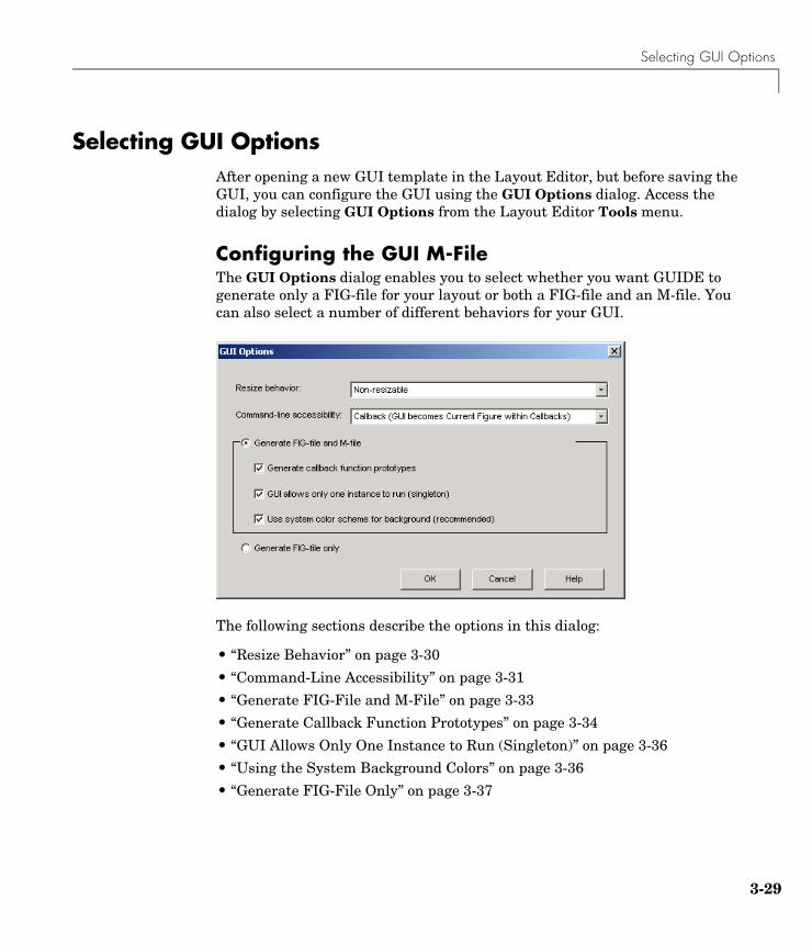
Selecting GUI Options
3-29
Selecting GUI OptionsAfter opening a new GUI template in the Layout Editor, but before saving the GUI, you can configure the GUI using the GUI Options dialog. Access the dialog by selecting GUI Options from the Layout Editor Tools menu.
Configuring the GUI M-FileThe GUI Options dialog enables you to select whether you want GUIDE to generate only a FIG-file for your layout or both a FIG-file and an M-file. You can also select a number of different behaviors for your GUI.
The following sections describe the options in this dialog:
• “Resize Behavior” on page 3-30
• “Command-Line Accessibility” on page 3-31
• “Generate FIG-File and M-File” on page 3-33
• “Generate Callback Function Prototypes” on page 3-34
• “GUI Allows Only One Instance to Run (Singleton)” on page 3-36
• “Using the System Background Colors” on page 3-36
• “Generate FIG-File Only” on page 3-37
3 Laying Out GUIs and Setting Properties
3-30
Resize BehaviorYou can control whether users can resize the figure window containing your GUI and how MATLAB handles resizing. GUIDE provides three options:
• Non-resizable — Users cannot change the window size (default).
• Proportional — MATLAB automatically rescales the components in the GUI in proportion to the new figure window size.
• Other (Use ResizeFcn) — Program the GUI to behave in a certain way when users resize the figure window.
The first two approaches simply set properties appropriately and require no other action. Other (Use ResizeFcn) requires you to write a callback routine that recalculates sizes and positions of the components based on the new figure size. The following sections discuss each approach.
Making Your GUI NonresizableCertain types of GUIs are typically nonresizable. Warning and simple question dialog boxes, particularly modal windows, are usually not resizable. After a simple interaction, users dismiss these GUIs so changing their size is not necessary.
Property Settings. GUIDE sets the following properties to create nonresizable GUIs:
• Units properties of the figure, axes, user interface controls, panels, and button groups are set to characters (the Layout Editor default) so the GUI displays at the correct size on different computers.
• Resize figure property is set to off.
• ResizeFcn figure property is left unset.
Allowing Proportional GUI ResizingUse this approach if you want to allow users to resize the GUI and are satisfied with a behavior that simply scales each component’s size and relative position in proportion to the new figure size. Note that the font size of component labels does not resize and, if the size is reduced enough, these labels may become unreadable. This approach works well with simple GUI tools and dialog boxes that apply settings without closing.
Selecting GUI Options
3-31
Property Settings. GUIDE sets the following properties to create proportional resizing GUIs:
• Units properties of the axes, user interface controls, panels, and button groups are set to normalized so that these components resize and reposition as the figure window changes size.
• Units property of the figure is set to characters so the GUI displays at the correct size at run-time, based on any changes in font size.
• Resize figure property set to on (the default).
• ResizeFcn figure property is left unset.
User-Specified Resize OperationYou can create GUIs that accommodate resizing, while at the same time maintain the appearance and usability of your original design by programming the figure ResizeFcn callback routine. This callback routine allows you to recalculate the size and position of each component based on the new figure size.
This approach to handling figure resizing is used most typically in GUI-based applications that require user interaction on an ongoing basis. Such an application might contain axes for displaying data and various components whose position and size are critical to the successful use of the interface.
Property Settings. GUIDE sets the following properties to implement this style of GUI:
• Units properties of the figure, axes, user interface controls, panels, and button groups are set to characters so the GUI displays at the correct size at run-time.
• Resize figure property is set to on (the default).
• ResizeFcn figure property requires a callback routine to handle resizing.
See “The Address Book Resize Function” on page 5-43 for an example of a user-written resize function.
Command-Line AccessibilityYou can restrict access to the GUI figure handle from the command line with the Command-line accessibility options. This prevents users from inadvertently changing the appearance of the GUI by entering commands,
3 Laying Out GUIs and Setting Properties
3-32
such as plot, that alter the current figure. With the default option, which is Callback (GUI becomes Current Figure within Callbacks), the GUI can become the MATLAB current figure, by the command gcf, only while a callback is executing.
There may be occasions when you want the GUI figure handle to be accessible from the command line. For example, you might want the GUI to display plots created at the command line. In this case, you should select On (GUI may become Current Figure from Command Line).
Access OptionsThere are four options for Command-line accessibility:
• Callback (GUI becomes Current Figure within Callbacks)
• Off (GUI never becomes Current Figure)
• On (GUI may become Current Figure from Command Line)
• Other (Use settings from Property Inspector)
The following table summarizes how the four Command-line accessibility options configure HandleVisibility and IntegerHandle in the Property Inspector (see Figure Properties That Control Access):
Figure Properties That Control AccessThere are two figure properties that control command-line accessibility of the figure:
• HandleVisibility — Determines whether the figure’s handle is visible to commands that attempt to access the current figure.
• IntegerHandle — Determines if a figure’s handle is an integer or a floating-point value.
Option Handle Visibility Integer Handle
Callback Callback off
Off off off
On on on
Other user specifies user specifies
Selecting GUI Options
3-33
HandleVisibility — Callback. Setting HandleVisibility to callback causes handles to be visible from within callback routines or functions invoked by callback routines, but not from within functions invoked from the command line. This provides a means to protect GUIs from command-line users, while allowing callback routines to have complete access to object handles. You should use this option if your GUI contains axes.
HandleVisibility — Off. Setting the HandleVisibility property to off removes the handle of the figure from the list of root object children so it will not become the current figure (which is the target for graphics output). The handle remains valid, however, so a command that specifies the handle explicitly still works (such as close(1)). However, you cannot use commands that operate only on the current figure or axes. These commands include xlabel, ylabel, zlabel, title, gca, gcf, and findobj.
HandleVisibility — On. Handles are always visible when HandleVisibility is on.
IntegerHandle. Setting the IntegerHandle property to off causes MATLAB to assign nonreusable real-number handles (e.g., 67.0001221...) instead of integers. This greatly reduces the likelihood of someone accidently performing an operation on the figure.
Using findobjWhen you set the Command-line accessibility to off, the handle of the GUI figure is hidden. This means you cannot use findobj to locate the handles of the uicontrols in the GUI. As an alternative, the GUI M-file creates an object handle structure that contains the handles of each uicontrol in the GUI and passes this structure to subfunctions.
Generate FIG-File and M-FileSelect Generate FIG-file and M-file in the GUI Options dialog if you want GUIDE to create both the FIG-file and the GUI M-file (this is the default). Once you have selected this option, you can select any of the following items in the frame to configure the M-file:
• Generate callback function prototypes
• Application allows only one instance to run (singleton)
• Use system color scheme for background
3 Laying Out GUIs and Setting Properties
3-34
Generate Callback Function PrototypesWhen you select Generate callback function prototypes in the GUI Options dialog, GUIDE adds the most commonly used subfunctions to the GUI M-file for any component you add to the GUI. You must then write the code for the callback in this subfunction.
GUIDE also adds a subfunction whenever you edit a callback routine from the Layout Editor’s right-click context menu and when you add menus to the GUI using the Menu Editor.
Naming Callback SubfunctionsWhen you add a component to your GUI layout, GUIDE assigns a value to its Tag property, which is then used to generate the name of the callback.
For example, the first push button you add to the layout is tagged pushbutton1. When generating the M-file, GUIDE adds a callback subfunction called pushbutton1_Callback. If you define a ButtonDownFcn for the same push button, GUIDE names its subfunction pushbutton1_ButtonDownFcn.
Callback Function SyntaxThe callback function syntax is of the form
function objectTag_Callback(hObject, eventdata, handles)
The arguments are listed in the following table.
For example, if you create a layout having a push button whose Tag property is set to pushbutton1, then GUIDE generates the following subfunction header in the GUI M-file.
Argument Description
hObject The handle of the object whose callback is executing.
eventdata Empty — reserved for future use.
handles A structure containing the handles of all components in the GUI whose fieldnames are defined by the object’s Tag property. Can also be used to pass data to other callback functions or the command line.
Selecting GUI Options
3-35
function pushbutton1_Callback(hObject, eventdata, handles)
Assigning a Callback Property StringWhen you first add a component to your GUI layout, its Callback property is set to the string %automatic. This string signals GUIDE to replace it with one that calls the appropriate callback subfunction in the GUI M-file when you save or run the GUI. For example, GUIDE sets the Callback property for pushbutton1 uicontrol to
my_gui('pushbutton1_Callback',gcbo,[],guidata(gcbo))
where
• my_gui is the name of the GUI M-file.
• pushbutton1 is the value of the component’s Tag property.
• pushbutton1_Callback is the name of the callback routine subfunction defined in my_gui.
• gcbo is a command that returns the handle of the callback object (i.e., pushbutton1).
• [] is a place holder for the currently unused eventdata argument.
• guidata(gcbo) returns the handles structure.
See “Callback Function Syntax” on page 3-34 for more information on callback function arguments and “Changing Tag and Callback Properties” on page 3-57 for more information on how to change the names used by GUIDE.
Adding Callbacks to the M-fileIf you want GUIDE to include other callbacks in the GUI M-file and provide names for them, you can do one of the following:
• In the Property Inspector, set the value of the callback property, e.g., KeyPressFcn, to the string %automatic. GUIDE adds the callback to the M-file the next time you save the GUI.
• In the View menu, select View Callbacks. Then select the desired callback, e.g., KeyPressFcn. GUIDE adds the callback to the M-file, opens the M-file if it is not already open, and scrolls to the first line of the new callback.
3 Laying Out GUIs and Setting Properties
3-36
GUI Allows Only One Instance to Run (Singleton)This option allows you to select between two behaviors for the GUI figure:
• Allow MATLAB to display only one instance of the GUI at a time.
• Allow MATLAB to display multiple instances of the GUI.
If you allow only one instance, MATLAB reuses the existing GUI figure whenever the command to run the GUI is issued. If a GUI already exists, MATLAB brings it to the foreground rather than creating a new figure.
If you clear this option, MATLAB creates a new GUI figure whenever you issue the command to run the GUI.
Using the System Background ColorsThe color used for GUI components varies on different computer systems. This option enables you to make the figure background color the same as the default uicontrol background color, which is system dependent.
If you select Use system color scheme for background (the default), GUIDE changes the figure background color to match the color of the GUI components.
The following figures illustrate the results with and without system color matching.
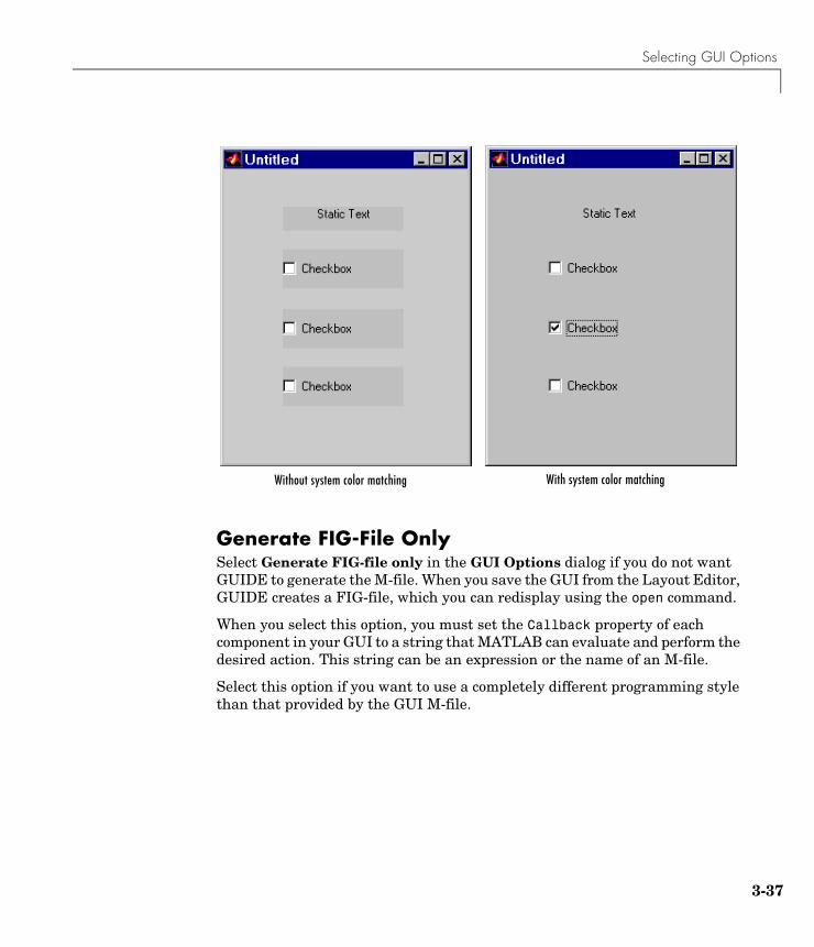
Selecting GUI Options
3-37
Generate FIG-File OnlySelect Generate FIG-file only in the GUI Options dialog if you do not want GUIDE to generate the M-file. When you save the GUI from the Layout Editor, GUIDE creates a FIG-file, which you can redisplay using the open command.
When you select this option, you must set the Callback property of each component in your GUI to a string that MATLAB can evaluate and perform the desired action. This string can be an expression or the name of an M-file.
Select this option if you want to use a completely different programming style than that provided by the GUI M-file.
With system color matchingWithout system color matching
3 Laying Out GUIs and Setting Properties
3-38
Aligning Components in the Layout EditorYou can select and drag any component or group of components that has the same parent within the layout area. In addition, the Layout Editor provides a number of features that facilitate more precise alignment of objects with respect to one another:
• Alignment Tool — align and distribute groups of components.
• Grid and Rulers — align components on a grid with optional snap to grid.
• Guide Lines — vertical and horizontal snap-to guides at arbitrary locations.
• Bring to Front, Send to Back, Bring Forward, Send Backward — control the front to back arrangement of components.
Aligning Groups of Components — The Alignment ToolThe Alignment Tool enables you to position objects with respect to each other and to adjust the spacing between selected objects. The specified alignment operations apply to all components that are selected when you press the Apply button.
Note To select multiple components, they must be contained in the same figure, panel, or button group.

Aligning Components in the Layout Editor
3-39
The alignment tool provides two types of alignment operations:
• Align — align all selected components to a single reference line.
• Distribute — space all selected components uniformly with respect to each other.
Both types of alignment can be applied in the vertical and horizontal directions. Note that, in many cases, it is better to apply alignments independently to the vertical or to the horizontal using two separate steps.
Align OptionsThere are both vertical and horizontal align options. Each option aligns selected components to a reference line, which is determined by the bounding box that encloses the selected objects. For example, the following picture of the layout area shows the bounding box (indicated by the dashed line) formed by three selected push buttons.
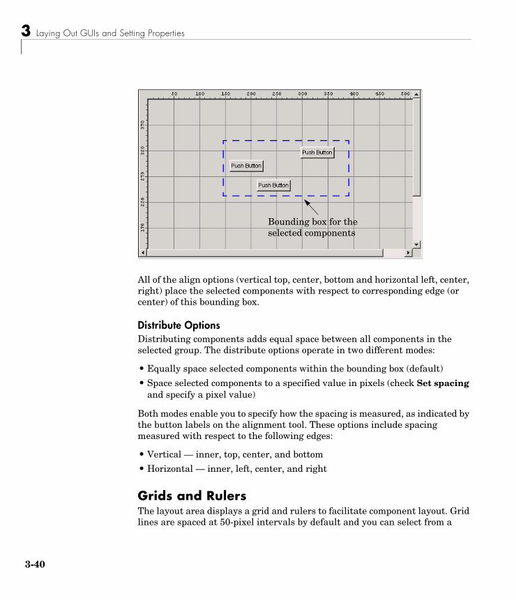
3 Laying Out GUIs and Setting Properties
3-40
All of the align options (vertical top, center, bottom and horizontal left, center, right) place the selected components with respect to corresponding edge (or center) of this bounding box.
Distribute OptionsDistributing components adds equal space between all components in the selected group. The distribute options operate in two different modes:
• Equally space selected components within the bounding box (default)
• Space selected components to a specified value in pixels (check Set spacing and specify a pixel value)
Both modes enable you to specify how the spacing is measured, as indicated by the button labels on the alignment tool. These options include spacing measured with respect to the following edges:
• Vertical — inner, top, center, and bottom
• Horizontal — inner, left, center, and right
Grids and RulersThe layout area displays a grid and rulers to facilitate component layout. Grid lines are spaced at 50-pixel intervals by default and you can select from a
Bounding box for the selected components
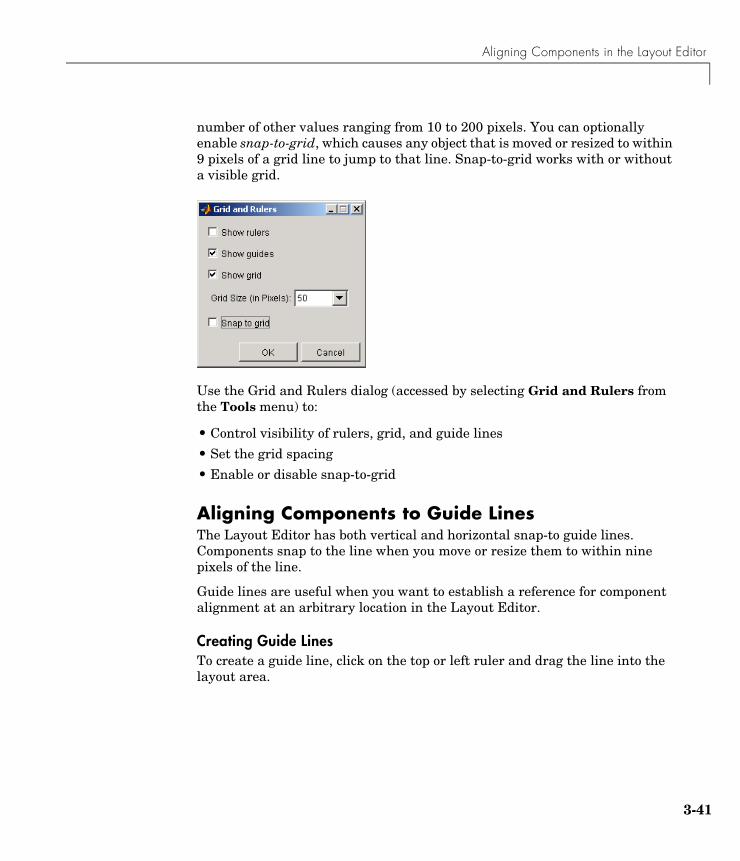
Aligning Components in the Layout Editor
3-41
number of other values ranging from 10 to 200 pixels. You can optionally enable snap-to-grid, which causes any object that is moved or resized to within 9 pixels of a grid line to jump to that line. Snap-to-grid works with or without a visible grid.
Use the Grid and Rulers dialog (accessed by selecting Grid and Rulers from the Tools menu) to:
• Control visibility of rulers, grid, and guide lines
• Set the grid spacing
• Enable or disable snap-to-grid
Aligning Components to Guide LinesThe Layout Editor has both vertical and horizontal snap-to guide lines. Components snap to the line when you move or resize them to within nine pixels of the line.
Guide lines are useful when you want to establish a reference for component alignment at an arbitrary location in the Layout Editor.
Creating Guide LinesTo create a guide line, click on the top or left ruler and drag the line into the layout area.
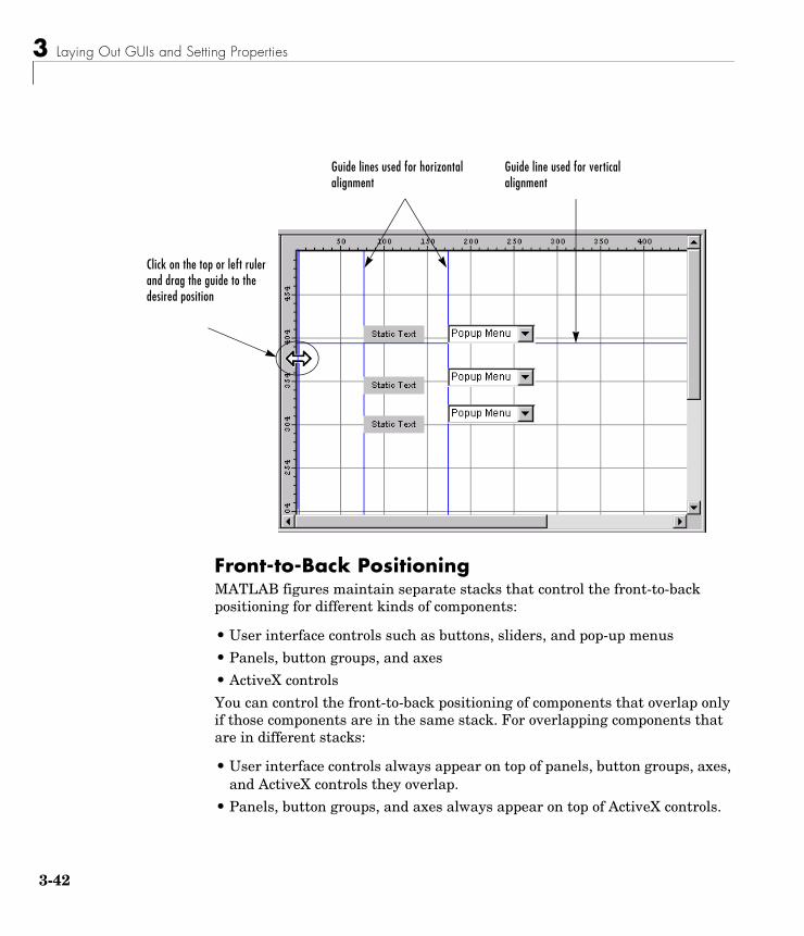
3 Laying Out GUIs and Setting Properties
3-42
Front-to-Back PositioningMATLAB figures maintain separate stacks that control the front-to-back positioning for different kinds of components:
• User interface controls such as buttons, sliders, and pop-up menus
• Panels, button groups, and axes
• ActiveX controls
You can control the front-to-back positioning of components that overlap only if those components are in the same stack. For overlapping components that are in different stacks:
• User interface controls always appear on top of panels, button groups, axes, and ActiveX controls they overlap.
• Panels, button groups, and axes always appear on top of ActiveX controls.
Guide lines used for horizontal alignment
Click on the top or left ruler and drag the guide to the desired position
Guide line used for vertical alignment
Aligning Components in the Layout Editor
3-43
The Layout Editor provides four operations that enable you to control front-to-back positioning:
• Bring to Front — move the selected object(s) in front of nonselected objects (available from the right-click context menu, the Layout menu, or the Ctrl+F shortcut).
• Send to Back — move the selected object(s) behind nonselected objects (available from the right-click context menu, the Layout menu, or the Ctrl+B shortcut).
• Bring Forward — move the selected object(s) forward by one level, i.e., in front of the object directly forward of it, but not in front of all objects that overlay it (available from the Layout menu).
• Send Backward — move the selected object(s) back by one level, i.e., behind the object directly in back of it, but not behind all objects that are behind it (available from the Layout menu).
3 Laying Out GUIs and Setting Properties
3-44
Setting Component Properties — The Property InspectorThe Property Inspector enables you to set the properties of the components in your layout. It provides a list of all settable properties and displays the current value. Each property in the list is associated with an editing device that is appropriate for the values accepted by the particular property. For example, a color picker to change the BackgroundColor, a pop-up menu to set FontAngle, and a text field to specify the Callback string.
See “Programming Callbacks for GUI Components” on page 4-8 to learn how to use these properties when you program callbacks.
This section covers the following topics:
• “Displaying the Property Inspector” on page 3-44
• “What Properties Do I Need to Set?” on page 3-45
• “Some Commonly Used Properties” on page 3-46
• “Setting Properties for Some Specific Components” on page 3-48
• “Changing a Tag” on page 3-57
Displaying the Property InspectorYou can display the Property Inspector by any of the following actions:
• Double-clicking on a component in the Layout Editor
• Selecting Property Inspector in the View menu
• Right-clicking on a component and selecting Inspect Properties from the context menu
This displays the Property Inspector, as shown in the following figure.
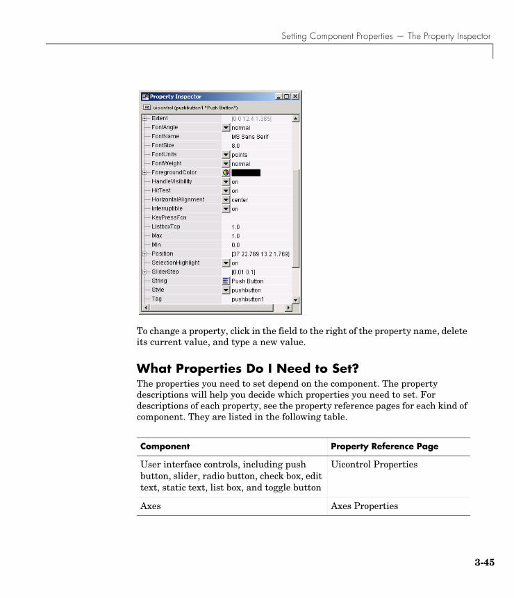
Setting Component Properties — The Property Inspector
3-45
To change a property, click in the field to the right of the property name, delete its current value, and type a new value.
What Properties Do I Need to Set?The properties you need to set depend on the component. The property descriptions will help you decide which properties you need to set. For descriptions of each property, see the property reference pages for each kind of component. They are listed in the following table.
Component Property Reference Page
User interface controls, including push button, slider, radio button, check box, edit text, static text, list box, and toggle button
Uicontrol Properties
Axes Axes Properties
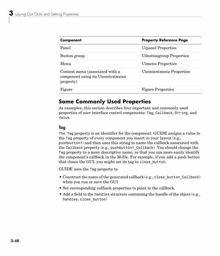
3 Laying Out GUIs and Setting Properties
3-46
Some Commonly Used PropertiesAs examples, this section describes four important and commonly used properties of user interface control components: Tag, Callback, String, and Value.
TagThe Tag property is an identifier for the component. GUIDE assigns a value to the Tag property of every component you insert in your layout (e.g., pushbutton1) and then uses this string to name the callback associated with the Callback property (e.g., pushbutton1_Callback). You should change the Tag property to a more descriptive name, so that you can more easily identify the component’s callback in the M-file. For example, if you add a push button that closes the GUI, you might set its tag to close_button.
GUIDE uses the Tag property to
• Construct the name of the generated callback (e.g., close_button_Callback) when you run or save the GUI
• Set corresponding callback properties to point to the callback.
• Add a field to the handles structure containing the handle of the object (e.g., handles.close_button)
Panel Uipanel Properties
Button group Uibuttongroup Properties
Menu Uimenu Properties
Context menu (associated with a component using its Uicontextmenu property)
Uicontextmenu Properties
Figure Figure Properties
Component Property Reference Page
Setting Component Properties — The Property Inspector
3-47
Note Since GUIDE uses the Tag property to name functions and structure fields, the tag you select must be a valid MATLAB variable name. Use isvarname to determine if the string you want to use is valid.
CallbackThe Callback property specifies the callback that is executed in the GUI M-file when a user activates the component.
StringThe String property contains text for the component. The following are examples:
• For buttons, check boxes, list boxes, edit text, and static text, the String text is displayed on or next to the component.
• For an edit text, the String property contains a list of strings that is displayed in the text box. When a user edits the text, the String property is updated.
Note Except for the edit text, if the String you specify does not fit in the component, the text is clipped in the active GUI and an ellipsis (...) is appended. However, the ellipsis does not appear in the GUIDE Layout Editor.
ValueThe Value property contains a numerical value for the component, which must lie in the range specified by the Max and Min properties. The following are examples:
• For radio buttons and check boxes, Max and Min are set to 1 and 0, respectively, by default. The Value property is set to 1 when the radio button or check box is selected, and 0 when it is cleared.
• When a user drags a slider, the Value is set to a number between Max and Min corresponding to the location of the slider button.
3 Laying Out GUIs and Setting Properties
3-48
Setting Properties for Some Specific ComponentsThis section describes how to set properties for some specific components. The section covers the following topics:
• “Setting Radio Button Properties” on page 3-48
• “Setting Edit Text Box Properties” on page 3-48
• “Setting List Box Properties” on page 3-49
• “Setting Slider Properties” on page 3-49
• “Setting Pop-Up Menu Properties” on page 3-51
• “Enabling or Disabling Controls” on page 3-52
• “Setting Panel and Button Group Properties” on page 3-53
Setting Radio Button PropertiesRadio buttons have two states — selected and not selected. You can query and set the state of a radio button through its Value property:
• Value = Max, button is selected (1 by default)
• Value = Min, button is not selected (0 by default)
To make radio buttons mutually exclusive within a group, the callback for each radio button must set the Value property to 0 on all other radio buttons in the group. MATLAB sets the Value property to 1 on the radio button clicked by the user.
The following subfunction, when added to the GUI M-file, can be called by each radio button callback. The argument is an array containing the handles of all other radio buttons in the group that must be cleared.
function mutual_exclude(off)set(off,'Value',0)
See “Radio Buttons” on page 4-9 for an example of such a function.
Setting Edit Text Box PropertiesThe values of the Min and Max properties for an edit text box determine whether users can enter single or multiple lines of text:
• If Max Min > 1, editable text boxes accept multiline input.
• If Max Min <= 1, editable text boxes accept only single-line input.
Setting Component Properties — The Property Inspector
3-49
Setting List Box Properties List boxes display a list of items and enable users to select one or more items. The String property contains the list of strings displayed in the list box. The first item in the list has an index of 1. Enter the list box items using the Property Inspector, one per line.
The values of the Min and Max properties for a list box determine whether users can select single or multiple lines of text:
• If Max Min > 1, users can select multiple lines.
• If Max Min <= 1, users can select only a single line.
The Value property contains the index into the list of strings that corresponds to the selected item. If the user selects multiple items, then Value is a vector of indices.
By default, the first item in the list is highlighted when the list box is first displayed. If you do not want any item highlighted, then set the Value property to empty, []. This works only when multiple selection is enabled.
The ListboxTop property defines which string in the list displays as the top most item when the list box is not large enough to display all list entries. ListboxTop is an index into the array of strings defined by the String property and must have a value between 1 and the number of strings. Noninteger values are fixed to the next lowest integer.
Selection Type. MATLAB sets Selection Type to normal on the first click and to open on the second click. The callback can query the Selection Type property to determine if it was a single- or double-click.
Setting Slider PropertiesThe following sections describe how to set properties for a slider.
Slider Orientation. You can orient the slider either horizontally or vertically by setting the relative width and height of the Position property:
• Horizontal slider — Width is greater than height.
• Vertical slider — Height is greater than width.
For example, these settings create a horizontal slider.
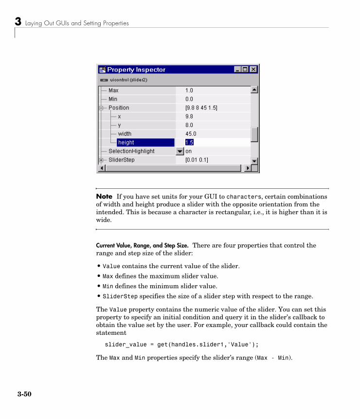
3 Laying Out GUIs and Setting Properties
3-50
Note If you have set units for your GUI to characters, certain combinations of width and height produce a slider with the opposite orientation from the intended. This is because a character is rectangular, i.e., it is higher than it is wide.
Current Value, Range, and Step Size. There are four properties that control the range and step size of the slider:
• Value contains the current value of the slider.
• Max defines the maximum slider value.
• Min defines the minimum slider value.
• SliderStep specifies the size of a slider step with respect to the range.
The Value property contains the numeric value of the slider. You can set this property to specify an initial condition and query it in the slider’s callback to obtain the value set by the user. For example, your callback could contain the statement
slider_value = get(handles.slider1,'Value');
The Max and Min properties specify the slider’s range (Max - Min).
Setting Component Properties — The Property Inspector
3-51
The SliderStep property controls the amount the slider Value property changes when you click the mouse on the arrow button or on the slider trough. Specify SliderStep as a two-element vector. The default, [0.01 0.10], provides a 1 percent change for clicks on an arrow and a 10 percent change for clicks in the trough. The actual step size is a function of the slider step and the slider range.
Designing a Slider. Suppose you want to create a slider with the following behavior:
• Slider range = 5 to 8
• Arrow step size = 0.4
• Trough step size = 1
• Initial value = 6.5
Set the following slider properties using the Property Inspector. X denotes the first element of the SliderStep vector. Y denotes the second element.
• SliderStep, X .133• SliderStep, Y .333• Max 8• Min 5• Value 6.5
SliderStep is a percentage of the slider range, which is 3. In this example, SliderStep for the arrow step size is 0.4/3 = 0.1333. SliderStep for the trough step size is 1/3 = 0.3333.
Setting Pop-Up Menu PropertiesPop-up menus open to display a list of choices when users click the arrow.
Adding Items to the Pop-Up Menu. The String property contains the list of strings displayed in the pop-up menu. Use the Property Inspector to add items to the pop-up menu by typing one per line in the String edit box:
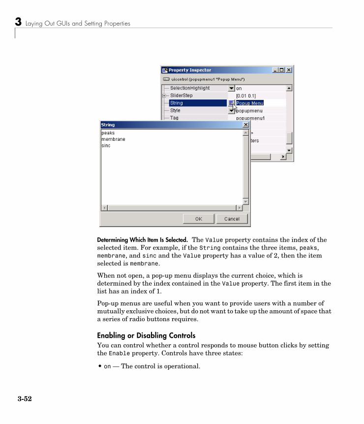
3 Laying Out GUIs and Setting Properties
3-52
Determining Which Item Is Selected. The Value property contains the index of the selected item. For example, if the String contains the three items, peaks, membrane, and sinc and the Value property has a value of 2, then the item selected is membrane.
When not open, a pop-up menu displays the current choice, which is determined by the index contained in the Value property. The first item in the list has an index of 1.
Pop-up menus are useful when you want to provide users with a number of mutually exclusive choices, but do not want to take up the amount of space that a series of radio buttons requires.
Enabling or Disabling ControlsYou can control whether a control responds to mouse button clicks by setting the Enable property. Controls have three states:
• on — The control is operational.
Setting Component Properties — The Property Inspector
3-53
• off — The control is disabled and its label (set by the string property) is grayed out.
• inactive — The control is disabled, but its label is not grayed out.
When a control is disabled, clicking on it with the left mouse button does not execute its callback routine. However, the left-click causes two other callback routines to execute:
1 First the figure WindowButtonDownFcn callback executes
2 Then the control’s ButtonDownFcn callback executes
A right mouse button click on a disabled control posts a context menu, if one is defined for that control. See the Enable property description for more details.
Setting Panel and Button Group PropertiesPanels and button groups group related components. A panel or button group can have a title and a border. You can also specify the background and border colors.
Title. Panel and button group properties enable you to set the title, as well as its font, font size, font angle, font weight, and its position relative to the panel. Suppose you want a panel with the title “Plot Types” and you want the title:
• Displayed in Times font, 12-point, italic, bold
• Positioned at the top right of the panel
Set the following panel properties:
• Title: Plot Types• FontName: Times• FontUnits: points• FontSize: 12• FontAngle: italic• FontWeight: bold• TitlePosition: righttop
Border. Suppose, in addition, you want the panel to have a 2-point wide, white and blue, beveled-out border.
3 Laying Out GUIs and Setting Properties
3-54
Set the following panel properties:
• BorderType: beveledout• BorderWidth: 2
• HighlightColor (white)- red: 1.0- green: 1.0- blue: 1.0
• ShadowColor (blue)- red: 0.0- green: 0.0- blue: 1.0
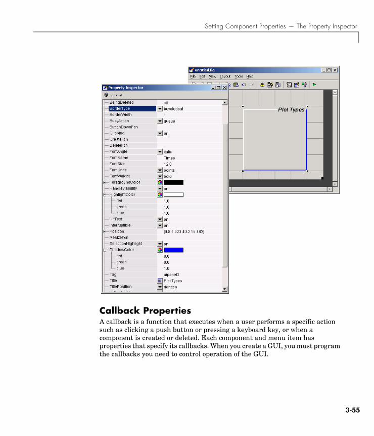
Setting Component Properties — The Property Inspector
3-55
Callback PropertiesA callback is a function that executes when a user performs a specific action such as clicking a push button or pressing a keyboard key, or when a component is created or deleted. Each component and menu item has properties that specify its callbacks. When you create a GUI, you must program the callbacks you need to control operation of the GUI.
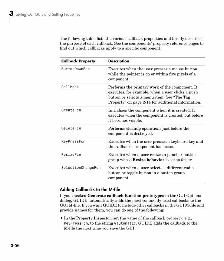
3 Laying Out GUIs and Setting Properties
3-56
The following table lists the various callback properties and briefly describes the purpose of each callback. See the components’ property reference pages to find out which callbacks apply to a specific component.
Adding Callbacks to the M-fileIf you checked Generate callback function prototypes in the GUI Options dialog, GUIDE automatically adds the most commonly used callbacks to the GUI M-file. If you want GUIDE to include other callbacks in the GUI M-file and provide names for them, you can do one of the following:
• In the Property Inspector, set the value of the callback property, e.g., KeyPressFcn, to the string %automatic. GUIDE adds the callback to the M-file the next time you save the GUI.
Callback Property Description
ButtonDownFcn Executes when the user presses a mouse button while the pointer is on or within five pixels of a component.
Callback Performs the primary work of the component. It executes, for example, when a user clicks a push button or selects a menu item. See “The Tag Property” on page 2-14 for additional information.
CreateFcn Initializes the component when it is created. It executes when the component is created, but before it becomes visible.
DeleteFcn Performs cleanup operations just before the component is destroyed.
KeyPressFcn Executes when the user presses a keyboard key and the callback’s component has focus.
ResizeFcn Executes when a user resizes a panel or button group whose Resize behavior is set to Other.
SelectionChangeFcn Executes when a user selects a different radio button or toggle button in a button group component.
Setting Component Properties — The Property Inspector
3-57
• In the View menu, select View Callbacks. Then select the desired callback, e.g., KeyPressFcn. GUIDE adds the callback to the M-file, opens the M-file if it is not already open, and scrolls to the first line of the new callback.
Changing Tag and Callback PropertiesThis section discusses what you need to keep in mind if you change a component’s tag or the value of any of its callback properties. This section covers the following topics:
• “Changing a Tag” on page 3-57
• “Changing Callback Properties” on page 3-57
Changing a Tag Once GUIDE generates the GUI M-file, if you subsequently change a component’s Tag in the Property Inspector, GUIDE can correctly update the following items according to the new Tag, provided that all components have distinct tags:
• The component’s callback functions in the M-file
• The value of component’s callback properties, which you can view in the Property Inspector
• References in the M-file to the field of the handles structure that contains the component’s handle
As an example, you might want to assign the same tag to each of a set of radio buttons if you want the same callback to service all of them. In this case, you must also change the name of the callback functions in their callback property values to be the same.
Changing Callback PropertiesYou can change the value of a callback property using the Property Inspector. The initial value of a callback property for a push button in an untitled GUI is similar to
untitled('pushbutton1_Callback',gcbo,[],guidata(gcbo))
where pushbutton1_Callback is the name of the callback function for that push button in the M-file.
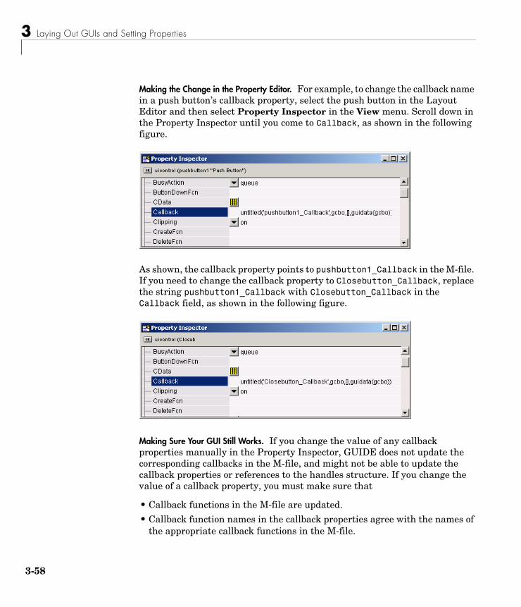
3 Laying Out GUIs and Setting Properties
3-58
Making the Change in the Property Editor. For example, to change the callback name in a push button’s callback property, select the push button in the Layout Editor and then select Property Inspector in the View menu. Scroll down in the Property Inspector until you come to Callback, as shown in the following figure.
As shown, the callback property points to pushbutton1_Callback in the M-file. If you need to change the callback property to Closebutton_Callback, replace the string pushbutton1_Callback with Closebutton_Callback in the Callback field, as shown in the following figure.
Making Sure Your GUI Still Works. If you change the value of any callback properties manually in the Property Inspector, GUIDE does not update the corresponding callbacks in the M-file, and might not be able to update the callback properties or references to the handles structure. If you change the value of a callback property, you must make sure that
• Callback functions in the M-file are updated.
• Callback function names in the callback properties agree with the names of the appropriate callback functions in the M-file.
Setting Component Properties — The Property Inspector
3-59
• References in the M-file to the field of the handles structure that contains the component’s handle are updated.
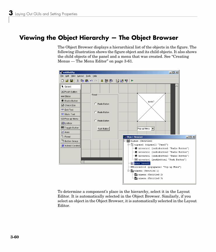
3 Laying Out GUIs and Setting Properties
3-60
Viewing the Object Hierarchy — The Object BrowserThe Object Browser displays a hierarchical list of the objects in the figure. The following illustration shows the figure object and its child objects. It also shows the child objects of the panel and a menu that was created. See “Creating Menus — The Menu Editor” on page 3-61.
To determine a component’s place in the hierarchy, select it in the Layout Editor. It is automatically selected in the Object Browser. Similarly, if you select an object in the Object Browser, it is automatically selected in the Layout Editor.
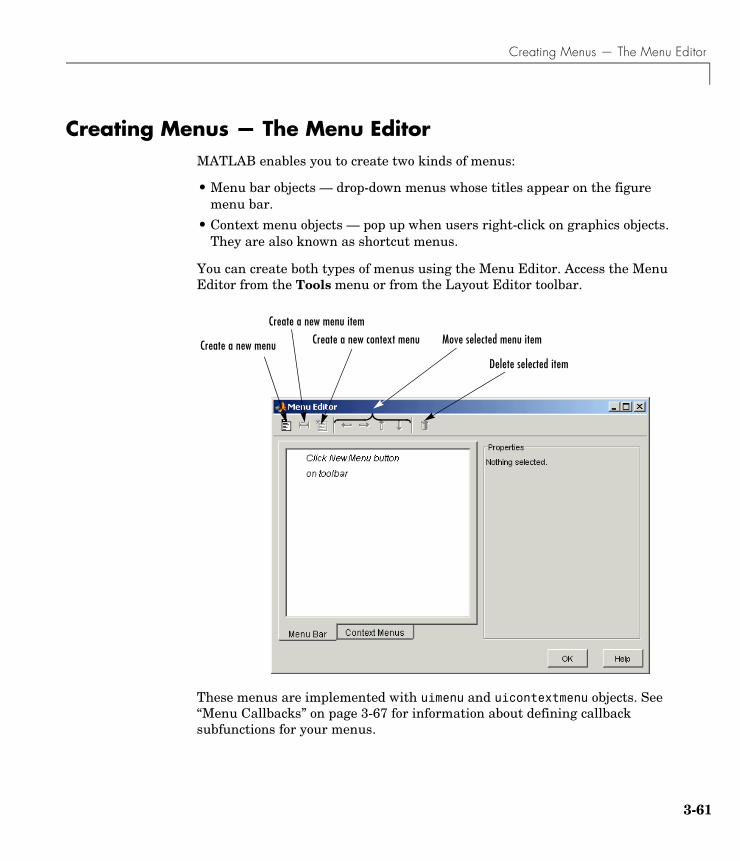
Creating Menus — The Menu Editor
3-61
Creating Menus — The Menu EditorMATLAB enables you to create two kinds of menus:
• Menu bar objects — drop-down menus whose titles appear on the figure menu bar.
• Context menu objects — pop up when users right-click on graphics objects. They are also known as shortcut menus.
You can create both types of menus using the Menu Editor. Access the Menu Editor from the Tools menu or from the Layout Editor toolbar.
These menus are implemented with uimenu and uicontextmenu objects. See “Menu Callbacks” on page 3-67 for information about defining callback subfunctions for your menus.
Create a new menu
Create a new menu item
Create a new context menu
Delete selected item
Move selected menu item
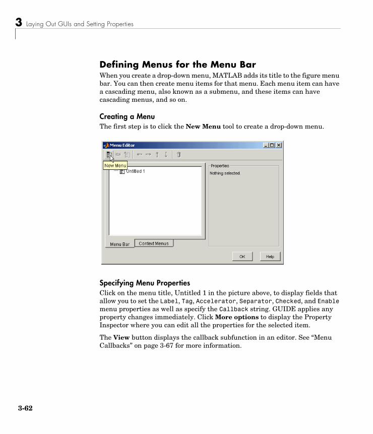
3 Laying Out GUIs and Setting Properties
3-62
Defining Menus for the Menu BarWhen you create a drop-down menu, MATLAB adds its title to the figure menu bar. You can then create menu items for that menu. Each menu item can have a cascading menu, also known as a submenu, and these items can have cascading menus, and so on.
Creating a MenuThe first step is to click the New Menu tool to create a drop-down menu.
Specifying Menu PropertiesClick on the menu title, Untitled 1 in the picture above, to display fields that allow you to set the Label, Tag, Accelerator, Separator, Checked, and Enable menu properties as well as specify the Callback string. GUIDE applies any property changes immediately. Click More options to display the Property Inspector where you can edit all the properties for the selected item.
The View button displays the callback subfunction in an editor. See “Menu Callbacks” on page 3-67 for more information.
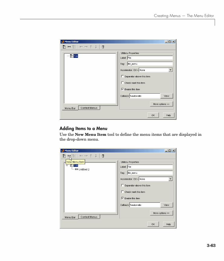
Creating Menus — The Menu Editor
3-63
Adding Items to a MenuUse the New Menu Item tool to define the menu items that are displayed in the drop-down menu.
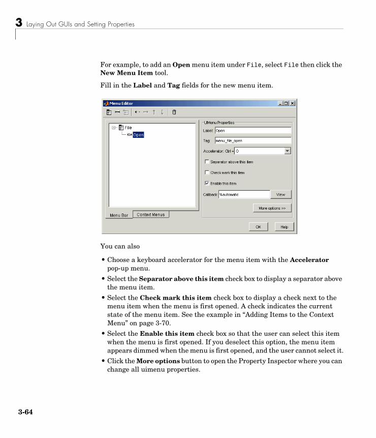
3 Laying Out GUIs and Setting Properties
3-64
For example, to add an Open menu item under File, select File then click the New Menu Item tool.
Fill in the Label and Tag fields for the new menu item.
You can also
• Choose a keyboard accelerator for the menu item with the Accelerator pop-up menu.
• Select the Separator above this item check box to display a separator above the menu item.
• Select the Check mark this item check box to display a check next to the menu item when the menu is first opened. A check indicates the current state of the menu item. See the example in “Adding Items to the Context Menu” on page 3-70.
• Select the Enable this item check box so that the user can select this item when the menu is first opened. If you deselect this option, the menu item appears dimmed when the menu is first opened, and the user cannot select it.
• Click the More options button to open the Property Inspector where you can change all uimenu properties.
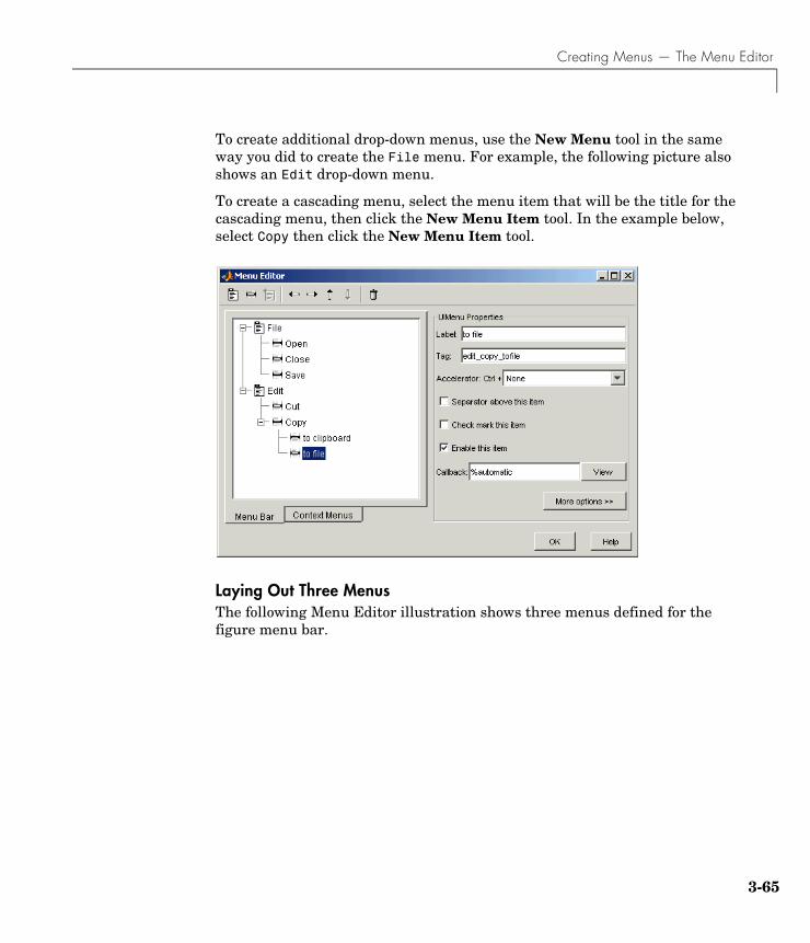
Creating Menus — The Menu Editor
3-65
To create additional drop-down menus, use the New Menu tool in the same way you did to create the File menu. For example, the following picture also shows an Edit drop-down menu.
To create a cascading menu, select the menu item that will be the title for the cascading menu, then click the New Menu Item tool. In the example below, select Copy then click the New Menu Item tool.
Laying Out Three MenusThe following Menu Editor illustration shows three menus defined for the figure menu bar.
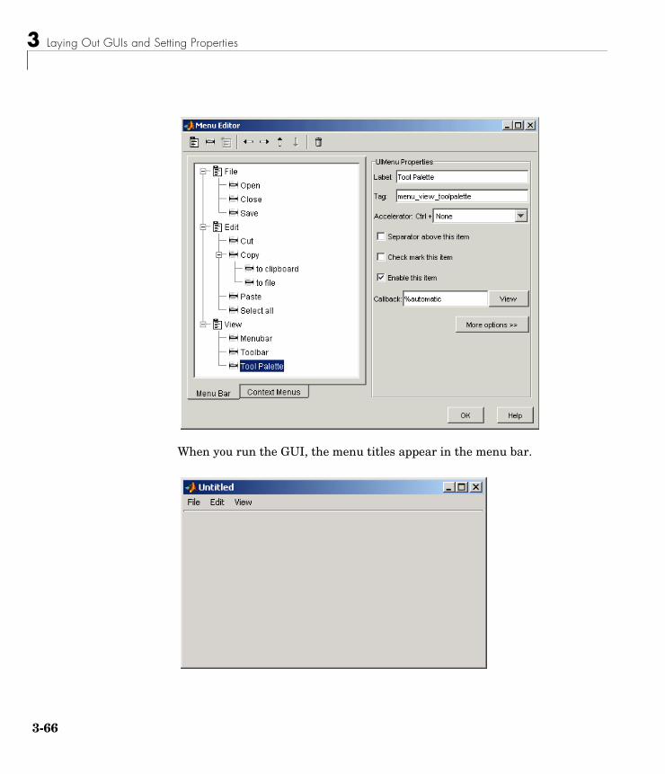
3 Laying Out GUIs and Setting Properties
3-66
When you run the GUI, the menu titles appear in the menu bar.
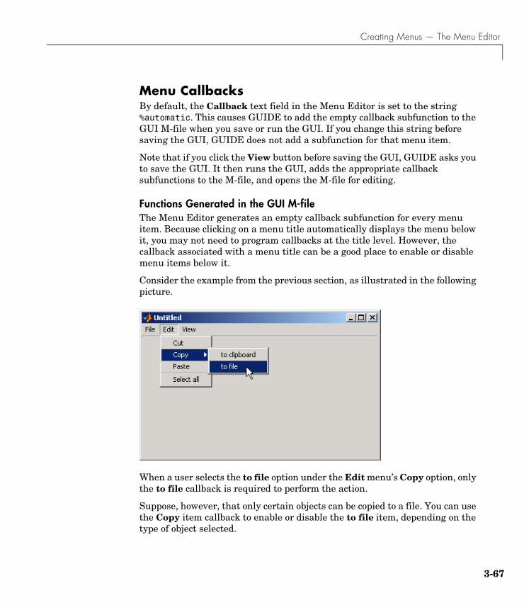
Creating Menus — The Menu Editor
3-67
Menu CallbacksBy default, the Callback text field in the Menu Editor is set to the string %automatic. This causes GUIDE to add the empty callback subfunction to the GUI M-file when you save or run the GUI. If you change this string before saving the GUI, GUIDE does not add a subfunction for that menu item.
Note that if you click the View button before saving the GUI, GUIDE asks you to save the GUI. It then runs the GUI, adds the appropriate callback subfunctions to the M-file, and opens the M-file for editing.
Functions Generated in the GUI M-fileThe Menu Editor generates an empty callback subfunction for every menu item. Because clicking on a menu title automatically displays the menu below it, you may not need to program callbacks at the title level. However, the callback associated with a menu title can be a good place to enable or disable menu items below it.
Consider the example from the previous section, as illustrated in the following picture.
When a user selects the to file option under the Edit menu’s Copy option, only the to file callback is required to perform the action.
Suppose, however, that only certain objects can be copied to a file. You can use the Copy item callback to enable or disable the to file item, depending on the type of object selected.
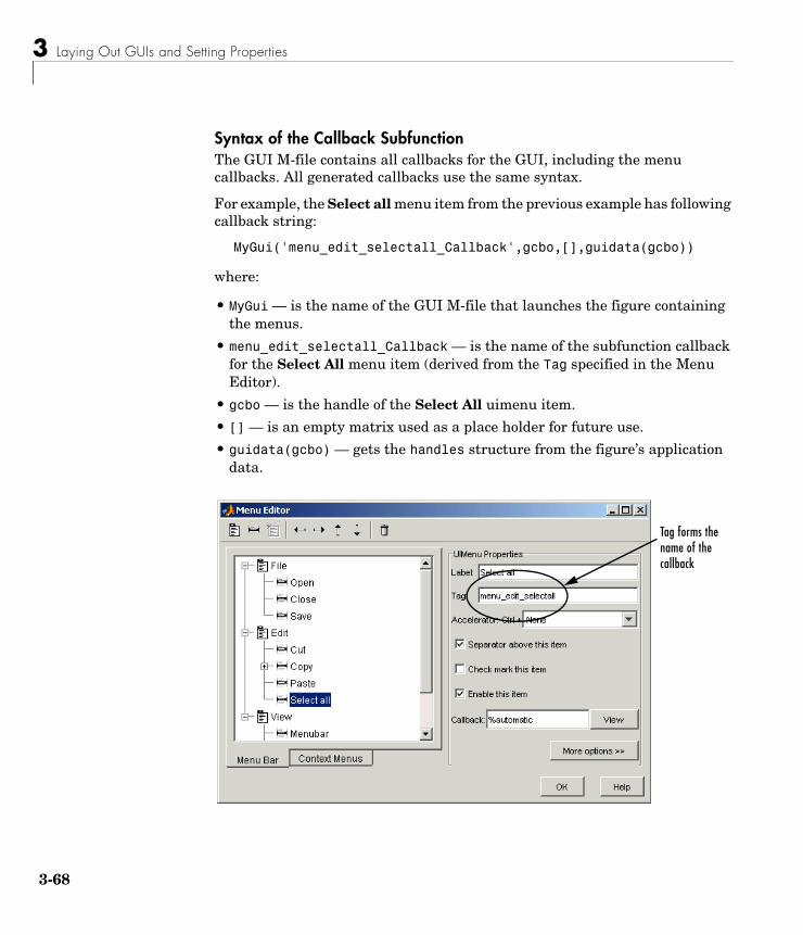
3 Laying Out GUIs and Setting Properties
3-68
Syntax of the Callback SubfunctionThe GUI M-file contains all callbacks for the GUI, including the menu callbacks. All generated callbacks use the same syntax.
For example, the Select all menu item from the previous example has following callback string:
MyGui('menu_edit_selectall_Callback',gcbo,[],guidata(gcbo))
where:
• MyGui — is the name of the GUI M-file that launches the figure containing the menus.
• menu_edit_selectall_Callback — is the name of the subfunction callback for the Select All menu item (derived from the Tag specified in the Menu Editor).
• gcbo — is the handle of the Select All uimenu item.
• [] — is an empty matrix used as a place holder for future use.
• guidata(gcbo) — gets the handles structure from the figure’s application data.
Tag forms the name of the callback
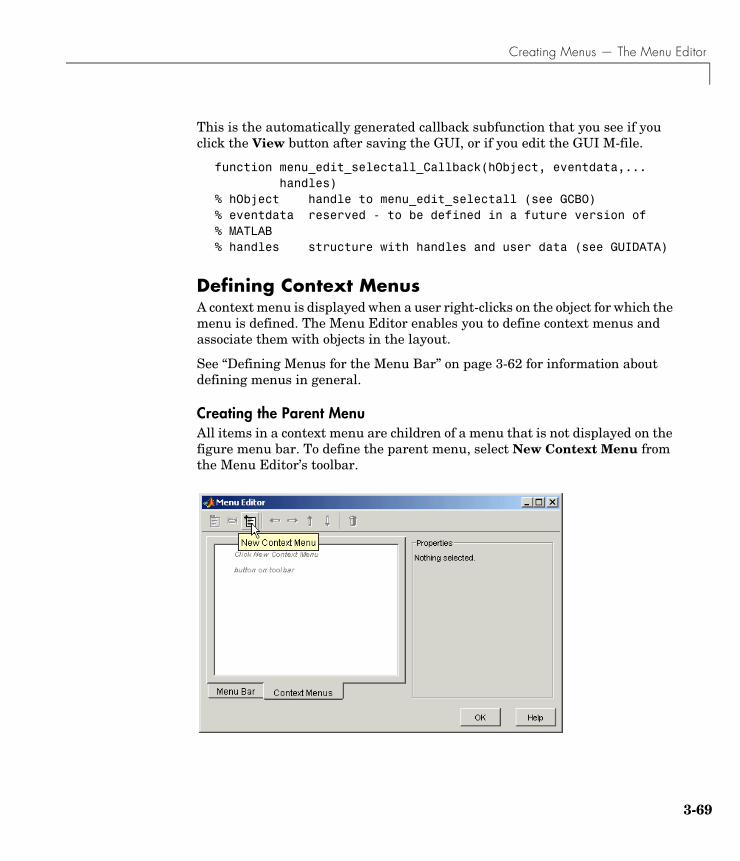
Creating Menus — The Menu Editor
3-69
This is the automatically generated callback subfunction that you see if you click the View button after saving the GUI, or if you edit the GUI M-file.
function menu_edit_selectall_Callback(hObject, eventdata,... handles)% hObject handle to menu_edit_selectall (see GCBO)% eventdata reserved - to be defined in a future version of % MATLAB% handles structure with handles and user data (see GUIDATA)
Defining Context MenusA context menu is displayed when a user right-clicks on the object for which the menu is defined. The Menu Editor enables you to define context menus and associate them with objects in the layout.
See “Defining Menus for the Menu Bar” on page 3-62 for information about defining menus in general.
Creating the Parent MenuAll items in a context menu are children of a menu that is not displayed on the figure menu bar. To define the parent menu, select New Context Menu from the Menu Editor’s toolbar.
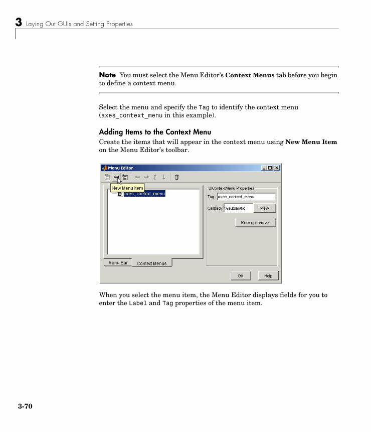
3 Laying Out GUIs and Setting Properties
3-70
Note You must select the Menu Editor’s Context Menus tab before you begin to define a context menu.
Select the menu and specify the Tag to identify the context menu (axes_context_menu in this example).
Adding Items to the Context MenuCreate the items that will appear in the context menu using New Menu Item on the Menu Editor’s toolbar.
When you select the menu item, the Menu Editor displays fields for you to enter the Label and Tag properties of the menu item.
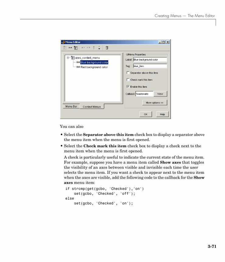
Creating Menus — The Menu Editor
3-71
You can also
• Select the Separator above this item check box to display a separator above the menu item when the menu is first opened.
• Select the Check mark this item check box to display a check next to the menu item when the menu is first opened.
A check is particularly useful to indicate the current state of the menu item. For example, suppose you have a menu item called Show axes that toggles the visibility of an axes between visible and invisible each time the user selects the menu item. If you want a check to appear next to the menu item when the axes are visible, add the following code to the callback for the Show axes menu item:if strcmp(get(gcbo, 'Checked'),'on') set(gcbo, 'Checked', 'off');else set(gcbo, 'Checked', 'on');
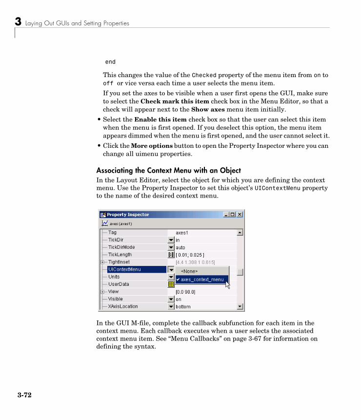
3 Laying Out GUIs and Setting Properties
3-72
end
This changes the value of the Checked property of the menu item from on to off or vice versa each time a user selects the menu item.
If you set the axes to be visible when a user first opens the GUI, make sure to select the Check mark this item check box in the Menu Editor, so that a check will appear next to the Show axes menu item initially.
• Select the Enable this item check box so that the user can select this item when the menu is first opened. If you deselect this option, the menu item appears dimmed when the menu is first opened, and the user cannot select it.
• Click the More options button to open the Property Inspector where you can change all uimenu properties.
Associating the Context Menu with an ObjectIn the Layout Editor, select the object for which you are defining the context menu. Use the Property Inspector to set this object’s UIContextMenu property to the name of the desired context menu.
In the GUI M-file, complete the callback subfunction for each item in the context menu. Each callback executes when a user selects the associated context menu item. See “Menu Callbacks” on page 3-67 for information on defining the syntax.
Setting the Tab Order
3-73
Setting the Tab OrderA GUI’s tab order is the order in which components of the GUI are selected when a user presses the Tab key on the keyboard.
The tab order for each level is determined independently. The figure is the base level, and each panel or button group establishes its own level. If, in tabbing through the components at the figure level, a user tabs to a panel or button group, then subsequent tabs sequence through the components of the panel or button group before returning to the level from which the panel or button group was reached.
The following topics discuss how to set the tab order.
• “The GUIDE Tab Order Editor” on page 3-73
• “Setting the Tab Order Programmatically” on page 3-75
Note The tab order also affects the stacking order of components. If components overlap, those that appear lower in the tabbing order, are drawn on top of those that appear higher in the order.
The GUIDE Tab Order EditorWhen you create a GUI, GUIDE sets the tab order at each level to be the order in which you add components to that level in the Layout Editor. This is often not the best order for the user.
The figure in the following GUI contains an axes, a slider, a panel, a static text, and a pop-up menu. Of these, only the slider, the panel, and the pop-up menu at the figure level can be tabbed. The panel contains three push buttons, which can all be tabbed.
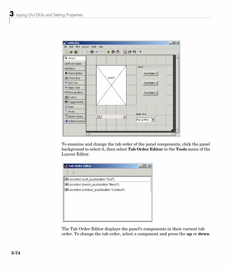
3 Laying Out GUIs and Setting Properties
3-74
To examine and change the tab order of the panel components, click the panel background to select it, then select Tab Order Editor in the Tools menu of the Layout Editor. .
The Tab Order Editor displays the panel’s components in their current tab order. To change the tab order, select a component and press the up or down
Setting the Tab Order
3-75
arrow to move the component up or down in the list. If you set the tab order for the three components in the example to be
1 Surf push button
2 Contour push button
3 Mesh push button
the user first tabs to the Surf push button, then to the Contour push button and then to the Mesh push button. Subsequent tabs sequence through the remaining components at the figure level.
Setting the Tab Order ProgrammaticallyYou can set the tab order programmatically by reordering the children in the Children property of the figure or of a container such as a uipanel.
Note The order in which the uicontrols appear in a child list is the reverse of the order in which they tab. This order also reflects the order in which the controls stack visually. I.e., if two components overlap, the item that appears first in the list shows up on top.
1 Get the vector of children of the GUI figure with a command similar to
HandlesOfChildren = get(HandleOfFigure,'Children');
2 Permute the HandlesOfChildren vector to suit your needs. For instance, to reverse the tab order:
ReversedChildren = flipud(HandlesOfChildren);
3 Reassign the permuted vector to the Children property of the figure:
set(HandleOfFigure,'Children',ReversedChildren);
3 Laying Out GUIs and Setting Properties
3-76
Note You can only assign a vector which is a permutation of the vector of children in this manner; you can't, for example, do the following because 0 is not the handle of a child of the figure:
set(HandleOfFigure,'Children',[0 HandlesOfChildren(2:end)]);
4
Programming GUIs
Understanding the GUI M-File (p. 4-2) The GUI M-file programs the GUI. This section describes the functioning of the GUI M-file, both the generated and user-written code.
Programming Callbacks for GUI Components (p. 4-8)
Explains how to program the callbacks for some specific GUI components.
Managing GUI Data with the Handles Structure (p. 4-27)
For GUIDE users, the handles structure provides easy access to all component handles in the GUI. In addition, you can use this structure to store all shared data required by your GUI.
Managing Application Data (p. 4-31) Application data enables you to save and retrieve named data associated with an object.
Designing for Cross-Platform Compatibility (p. 4-32)
Discusses the settings (used by default with GUIDE) that enable you to make your GUI look good on different computer platforms.
Types of Callbacks (p. 4-35) Shows you how to define callbacks. This section discusses the types available and their applications.
Interrupting Executing Callbacks (p. 4-37)
Describes how you can control whether user actions can interrupt executing callbacks.
Controlling Figure Window Behavior (p. 4-40)
Discusses how a GUI figure can block MATLAB execution and can be modal.
Example: Using the Modal Dialog to Confirm an Operation (p. 4-42)
Illustrates use of a modal dialog GUI to confirm that the user wants to proceed with an operation.
4 Programming GUIs
4-2
Understanding the GUI M-FileThe GUI M-file generated by GUIDE controls the GUI and determines how it responds to a user’s action, such as pressing a push button or selecting a menu item. The M-file contains all the code needed to run the GUI, including the callbacks for the GUI components. While GUIDE generates the framework for this M-file, you must program the callbacks, which are subfunctions of the M-file, to perform the functions you want them to.
This section explains the overall structure of the M-file. The section covers the following topics:
• “Sharing Data with the Handles Structure” on page 4-2
• “Functions and Callbacks in the M-File” on page 4-3
• “Opening Function” on page 4-4
• “Output Function” on page 4-5
• “Callbacks” on page 4-6
• “Input and Output Arguments” on page 4-7
To learn more about programming callbacks, see Subfunctions in the online MATLAB documentation.
Sharing Data with the Handles StructureWhen you run a GUI, the M-file creates a handles structure that contains all the data for GUI objects, such as controls, menus, and axes. The handles structure is passed as an input to each callback. You can use the handles structure to
• Share data between callbacks
• Access GUI data
Sharing Data To store data that is contained in a variable X, set a field of the handles structure equal to X and then save the handles structure with the guidata function:
handles.current_data = X;guidata(hObject,handles)
Understanding the GUI M-File
4-3
You can retrieve the data in any other callback with the command
X = handles.current_data;
For an example of sharing data between callbacks, see “Example: Passing Data Between Callbacks” on page 4-27.
For more information about handles, see “Managing GUI Data with the Handles Structure” on page 4-27.
Accessing GUI DataYou can access any of the data for the GUI components from the handles structure. For example, suppose your GUI has a pop-up menu, whose Tag is my_menu, containing three items, whose String properties are chocolate, strawberry, and vanilla. You want another component in the GUI — a push button, for example — to execute a command on the currently selected menu item. In the callback for the push button, you can insert the command
all_choices = get(handles.my_menu, 'String')current_choice = all_choices{get(handles.my_menu, 'Value')};
The command sets the value of current_choice to chocolate, strawberry, or vanilla, depending on which item is currently selected in the menu.
You can also access the data for the entire GUI from the handles structure. If the figure’s Tag is figure1, then
handles.figure1
contains the figure’s handle. For example, you can make the GUI close itself with the command
delete(handles.figure1)
For an example of closing a GUI with this command, look at the callback for the Close push button for the template described in “GUI with Axes and Menu” on page 3-5.
Functions and Callbacks in the M-FileYou can add code to the following parts of the GUI M-file:
• Opening function — executes before the GUI becomes visible to the user.
• Output function — outputs data to the command line, if necessary.
4 Programming GUIs
4-4
• Callbacks — execute each time the user activates the corresponding component of the GUI.
Common Input ArgumentsAll functions in the M-file have the following input arguments corresponding to the handles structure:
• hObject — the handle to the figure or Callback object
• handles — structure with handles and user data (see guidata)
The handles structure is saved at the end of each function with the command
guidata(hObject, handles);
Additional arguments for the opening and output functions are described in the following sections.
Opening FunctionThe opening function contains code that is executed just before the GUI is made visible to the user. You can access all the components for the GUI in the opening function, because all objects in the GUI are created before the opening function is called. You can add code to the opening function to perform tasks that need to be done before the user has access to the GUI — for example, creating data, plots or images, or making the GUI blocking with the uiwait command.
For a GUI whose file name is my_gui, the definition line for the opening function is
function my_gui_OpeningFcn(hObject, eventdata, handles, varargin)
Besides the arguments hObject and handles (see “Common Input Arguments” preceding), the opening function has the following input arguments:
• eventdata reserved for a future version of MATLAB
• varargin command line arguments to untitled (see varargin)
All command line arguments are passed to the opening function via varargin. If you open the GUI with a property name/property value pair as arguments, the GUI opens with the property set to the specified value. For example,
Understanding the GUI M-File
4-5
my_gui('Position', [71.8 44.9 74.8 19.7]) opens the GUI at the specified position, since Position is a valid figure property.
If the input argument is not a valid figure property, you must add code to the opening function to make use of the argument. For an example, look at the opening function for the modal question dialog template. The added code enables you to open the modal dialog with the syntax
my_gui('String','Do you want to exit?')
which displays the text 'Do you want to exit' on the GUI. In this case, it is necessary to add code to the opening function because 'String' is not a valid figure property.
Output FunctionThe output function returns output arguments to the command line. This is particularly useful if you want to return a variable to another GUI. For an example, see “Example: Using the Modal Dialog to Confirm an Operation” on page 4-42.
GUIDE generates the following lines of code in the output function:
% --- Outputs from this function are returned to the command line.function varargout = my_gui_OutputFcn(hObject, eventdata, handles)% Get default command line output from handles structurevarargout{1} = handles.output;
If the GUI is not blocking — in other words, if the M-file does not contain the command uiwait — the output is simply the handle to the GUI, which is assigned to handles.output in the opening function.
To make the GUI return a different output — for example, if you want it to return the result of a user response, such as pressing a push button — do the following:
• Add the command uiwait; to the opening function to make the M-file halt execution until a user activates a component in the GUI.
• For each component of the GUI where you expect a user response, make the callback update the value of handles.output, and execute uiresume.
4 Programming GUIs
4-6
For example, if the GUI contains a push button whose String property is 'Yes', add the following code to its callback to make the GUI return 'Yes' when the user presses the push button:
handles.output = 'Yes';guidata(hObject, handles);uiresume;
See the section “Managing GUI Data with the Handles Structure” on page 4-27 for more information about passing data with the handles structure.
When the GUI is called with the command
OUT = my_gui
and a user presses the Yes push button, the GUI returns the output OUT = 'Yes' to the command line.
The output varargout, which is a cell array, can contain any number of output arguments. By default, GUIDE creates just one output argument, handles.output. To create a second output argument, add the command
varargout{2} = handles.second_output;
to the output function. You can set the value of handles.second_output in any callback and then save it with the guidata command.
If you want, you can choose more descriptive names than output or second_output for the fields of the handles structure corresponding to the output arguments.
CallbacksWhen a user activates a component of the GUI, the GUI executes the corresponding callback. The name of the callback is determined by the component’s Tag property and the type of callback. For example, a push button with the Tag print_button executes the callback
function print_button_Callback(hObject, eventdata, handles)
Understanding the GUI M-File
4-7
Input and Output ArgumentsThe following examples illustrate various ways to call a GUI named my_gui with different arguments. All arguments are passed to the opening function in the GUI M-file.
• Calling my_gui with no arguments opens my_gui.
• Calling H = my_gui opens my_gui and returns the handle to my_gui.
• Calling my_gui('Property', Value,...), where 'Property' is a valid figure property, opens my_gui using the given property-value pair. You can call the GUI with more than one property-value pair.
For example, my_gui('Position', [71.8 44.9 74.8 19.7]) opens the GUI at the specified position, since Position is a valid figure property. See the reference page for figure for a list of figure properties.
• Calling my_gui('My_function', hObject, eventdata, handles,...) calls the subfunction My_function in the GUI M-file with the given input arguments.
• Calling my_gui('Key_word', Value,...), where 'Key_word' is any string that is not a valid figure property or the name of a subfunction, creates a new my_gui, and passes the pair 'Key_word', Value to the opening function in the GUI M-file via varargin.
You can use this calling syntax to pass arguments that are not figure properties to the GUI. For example, my_gui('Temperature', 98.6) opens the GUI and passes the vector ['Temperature', 98.6] to the opening function.
See “An Address Book Reader” on page 5-31 for an example that uses this syntax. The example creates a GUI called address_book. Calling the GUI with the syntax address_book('book', my_contacts) opens the GUI with the MAT-file my_contacts, which contains a list of names and addresses you want to display. Note that you can use any string that is not a valid figure property or the name of a callback in place of the string 'book'. See the reference page for figure for a list of figure properties.
Note If you call a GUI with multiple property value pairs, all the pairs that correspond to valid figure properties must precede all the pairs that do not correspond to valid figure properties in the sequence of arguments.
4 Programming GUIs
4-8
Programming Callbacks for GUI ComponentsThis section explains how to program the callbacks for some specific GUI components. “Callback Properties” on page 3-55 describes the different kinds of callbacks.
See a component’s property reference page to determine which callbacks apply for that component. “Setting Component Properties — The Property Inspector” on page 3-44 provides links to the property reference pages.
This section provides information on the following topics:
• “Toggle Button Callback” on page 4-8
• “Radio Buttons” on page 4-9
• “Check Boxes” on page 4-10
• “Edit Text” on page 4-10
• “Sliders” on page 4-11
• “List Boxes” on page 4-11
• “Pop-Up Menus” on page 4-12
• “Panels” on page 4-13
• “Button Groups” on page 4-13
• “Axes” on page 4-14
• “ActiveX Controls” on page 4-17
• “Figures” on page 4-25
Toggle Button CallbackThe callback for a toggle button needs to query the toggle button to determine what state it is in. MATLAB sets the Value property equal to the Max property when the toggle button is depressed (Max is 1 by default) and equal to the Min property when the toggle button is not depressed (Min is 0 by default).
From the GUI M-fileThe following code illustrates how to program the callback in the GUI M-file.
function togglebutton1_Callback(hObject, eventdata, handles)button_state = get(hObject,'Value');if button_state == get(hObject,'Max')
Programming Callbacks for GUI Components
4-9
% toggle button is pressed
elseif button_state == get(hObject,'Min')% toggle button is not pressed
end
Note If you have toggle buttons that are managed by a button group component, you must include the code to control them in the button group’s SelectionChangeFcn callback function, not in the individual toggle button Callback functions. A button group overwrites the Callback properties of radio buttons and toggle buttons that it manages. See “Button Groups” on page 4-13 for more information.
Adding an Image to a Push Button or Toggle ButtonAssign the CData property an m-by-n-by-3 array of RGB values that define a truecolor image. For example, the array a defines 16-by-128 truecolor image using random values between 0 and 1 (generated by rand).
a(:,:,1) = rand(16,128);a(:,:,2) = rand(16,128);a(:,:,3) = rand(16,128);set(hObject,'CData',a)
See ind2rgb for information on converting an (X, MAP) image to an RGB image.
Radio ButtonsYou can determine the current state of a radio button from within its callback by querying the state of its Value property, as illustrated in the following example:
if (get(hObject,'Value') == get(hObject,'Max'))% then radio button is selected-take approriate action
else% radio button is not selected-take approriate action
end
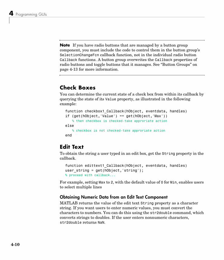
4 Programming GUIs
4-10
Note If you have radio buttons that are managed by a button group component, you must include the code to control them in the button group’s SelectionChangeFcn callback function, not in the individual radio button Callback functions. A button group overwrites the Callback properties of radio buttons and toggle buttons that it manages. See “Button Groups” on page 4-13 for more information.
Check Boxes You can determine the current state of a check box from within its callback by querying the state of its Value property, as illustrated in the following example:
function checkbox1_Callback(hObject, eventdata, handles)if (get(hObject,'Value') == get(hObject,'Max'))
% then checkbox is checked-take approriate action
else% checkbox is not checked-take approriate action
end
Edit Text To obtain the string a user typed in an edit box, get the String property in the callback.
function edittext1_Callback(hObject, eventdata, handles)user_string = get(hObject,'string');% proceed with callback...
For example, setting Max to 2, with the default value of 0 for Min, enables users to select multiple lines
Obtaining Numeric Data from an Edit Text ComponentMATLAB returns the value of the edit text String property as a character string. If you want users to enter numeric values, you must convert the characters to numbers. You can do this using the str2double command, which converts strings to doubles. If the user enters nonnumeric characters, str2double returns NaN.
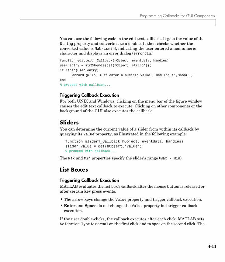
Programming Callbacks for GUI Components
4-11
You can use the following code in the edit text callback. It gets the value of the String property and converts it to a double. It then checks whether the converted value is NaN (isnan), indicating the user entered a nonnumeric character and displays an error dialog (errordlg).
function edittext1_Callback(hObject, eventdata, handles)
user_entry = str2double(get(hObject,'string'));
if isnan(user_entry)
errordlg('You must enter a numeric value','Bad Input','modal')
end
% proceed with callback...
Triggering Callback ExecutionFor both UNIX and Windows, clicking on the menu bar of the figure window causes the edit text callback to execute. Clicking on other components or the background of the GUI also executes the callback.
SlidersYou can determine the current value of a slider from within its callback by querying its Value property, as illustrated in the following example:
function slider1_Callback(hObject, eventdata, handles)slider_value = get(hObject,'Value');% proceed with callback...
The Max and Min properties specify the slider’s range (Max - Min).
List Boxes
Triggering Callback ExecutionMATLAB evaluates the list box’s callback after the mouse button is released or after certain key press events.
• The arrow keys change the Value property and trigger callback execution.
• Enter and Space do not change the Value property but trigger callback execution.
If the user double-clicks, the callback executes after each click. MATLAB sets Selection Type to normal on the first click and to open on the second click. The
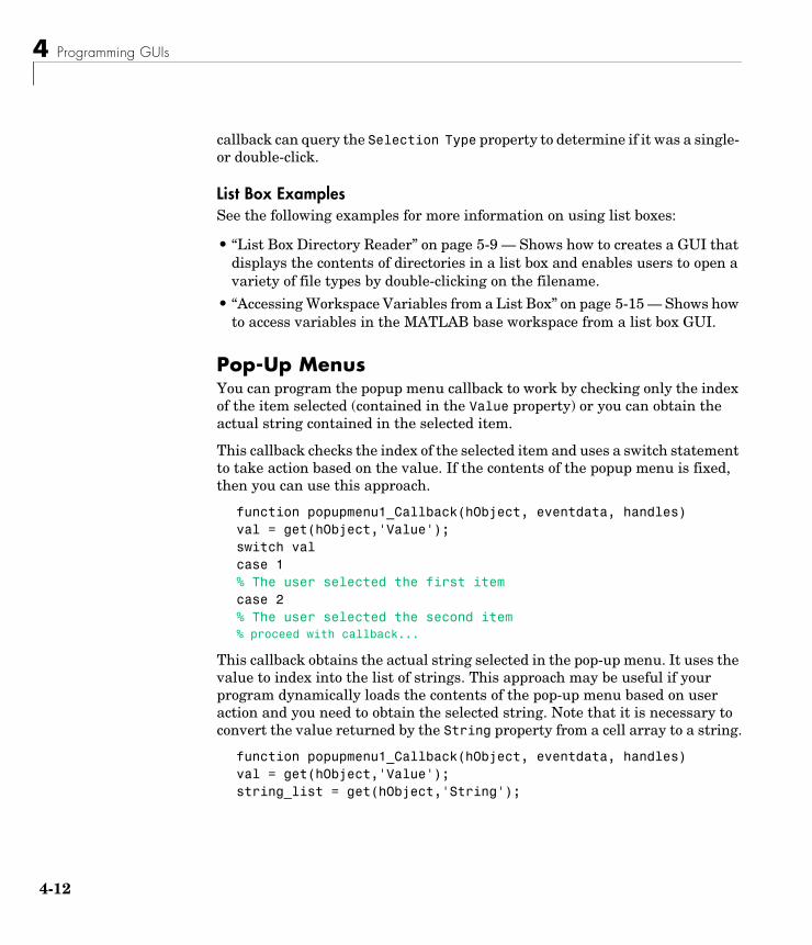
4 Programming GUIs
4-12
callback can query the Selection Type property to determine if it was a single- or double-click.
List Box ExamplesSee the following examples for more information on using list boxes:
• “List Box Directory Reader” on page 5-9 — Shows how to creates a GUI that displays the contents of directories in a list box and enables users to open a variety of file types by double-clicking on the filename.
• “Accessing Workspace Variables from a List Box” on page 5-15 — Shows how to access variables in the MATLAB base workspace from a list box GUI.
Pop-Up Menus You can program the popup menu callback to work by checking only the index of the item selected (contained in the Value property) or you can obtain the actual string contained in the selected item.
This callback checks the index of the selected item and uses a switch statement to take action based on the value. If the contents of the popup menu is fixed, then you can use this approach.
function popupmenu1_Callback(hObject, eventdata, handles)val = get(hObject,'Value');switch valcase 1% The user selected the first itemcase 2% The user selected the second item% proceed with callback...
This callback obtains the actual string selected in the pop-up menu. It uses the value to index into the list of strings. This approach may be useful if your program dynamically loads the contents of the pop-up menu based on user action and you need to obtain the selected string. Note that it is necessary to convert the value returned by the String property from a cell array to a string.
function popupmenu1_Callback(hObject, eventdata, handles)val = get(hObject,'Value');string_list = get(hObject,'String');
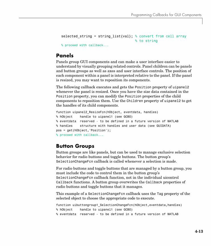
Programming Callbacks for GUI Components
4-13
selected_string = string_list{val}; % convert from cell array % to string% proceed with callback...
PanelsPanels group GUI components and can make a user interface easier to understand by visually grouping related controls. Panel children can be panels and button groups as well as axes and user interface controls. The position of each component within a panel is interpreted relative to the panel. If the panel is resized, you may want to reposition its components.
The following callback executes and gets the Position property of uipanel2 whenever the panel is resized. Once you have the size data contained in the Position property, you can modify the Position properties of the child components to reposition them. Use the Children property of uipanel2 to get the handles of its child components.
function uipanel2_ResizeFcn(hObject, eventdata, handles)
% hObject handle to uipanel1 (see GCBO)
% eventdata reserved - to be defined in a future version of MATLAB
% handles structure with handles and user data (see GUIDATA)
pos = get(hObject,'Position');
% proceed with callback...
Button GroupsButton groups are like panels, but can be used to manage exclusive selection behavior for radio buttons and toggle buttons. The button group’s SelectionChangeFcn callback is called whenever a selection is made.
For radio buttons and toggle buttons that are managed by a button group, you must include the code to control them in the button group’s SelectionChangeFcn callback function, not in the individual uicontrol Callback functions. A button group overwrites the Callback properties of radio buttons and toggle buttons that it manages.
This example of a SelectionChangeFcn callback uses the Tag property of the selected object to choose the appropriate code to execute.
function uibuttongroup1_SelectionChangeFcn(hObject,eventdata,handles)
% hObject handle to uipanel1 (see GCBO)
% eventdata reserved - to be defined in a future version of MATLAB
4 Programming GUIs
4-14
% handles structure with handles and user data (see GUIDATA)
switch get(hObject,'Tag') % Get Tag of selected object
case 'radiobutton1'
% code piece when radiobutton1 is selected goes here
case 'radiobutton2'
% code piece when radiobutton2 is selected goes here
% ...
end
Note For a uibuttongroup, contrary to the automatically generated comment, hObject is the handle of the selected radio button or toggle button, and not the handle of the uibuttongroup. Use handles.uipaneln as the handle of the uibuttongroup.
The code above refers to the handle of uipanel1 rather than the handle of uibuttongroup1, because a uibuttongroup is a kind of uipanel.
AxesAxes enable your GUI to display graphics (e.g., graphs and images). Like all graphics objects, axes have properties that you can set to control many aspects of its behavior and appearance. See “Axes Properties” in the MATLAB Graphics documentation for general information on axes objects.
Axes CallbacksAxes are not uicontrol objects, but can be programmed to execute a callback when users click a mouse button in the axes. Use the axes ButtonDownFcn property to define the callback.
Plotting to Axes in GUIsIf your GUI contains axes, you should make sure that the Command-line accessibility option in the GUI Options dialog is set to Callback (the default). This enables you to issue plotting commands from callbacks without explicitly specifying the target axes. See “Command-Line Accessibility” on page 3-31 for more information about how this option works.
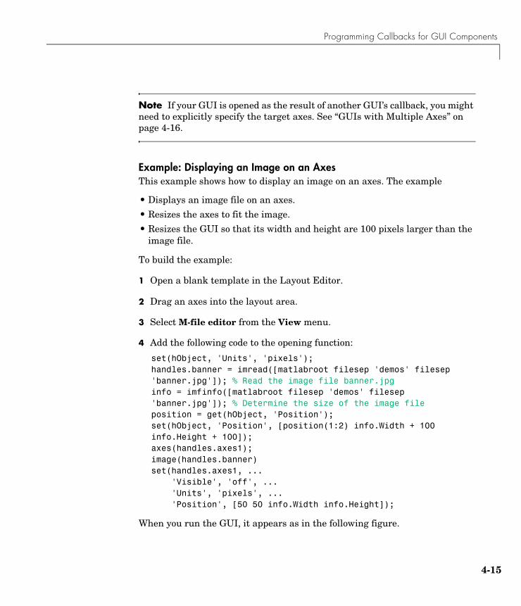
Programming Callbacks for GUI Components
4-15
Note If your GUI is opened as the result of another GUI’s callback, you might need to explicitly specify the target axes. See “GUIs with Multiple Axes” on page 4-16.
Example: Displaying an Image on an AxesThis example shows how to display an image on an axes. The example
• Displays an image file on an axes.
• Resizes the axes to fit the image.
• Resizes the GUI so that its width and height are 100 pixels larger than the image file.
To build the example:
1 Open a blank template in the Layout Editor.
2 Drag an axes into the layout area.
3 Select M-file editor from the View menu.
4 Add the following code to the opening function:
set(hObject, 'Units', 'pixels');handles.banner = imread([matlabroot filesep 'demos' filesep 'banner.jpg']); % Read the image file banner.jpginfo = imfinfo([matlabroot filesep 'demos' filesep 'banner.jpg']); % Determine the size of the image fileposition = get(hObject, 'Position');set(hObject, 'Position', [position(1:2) info.Width + 100 info.Height + 100]);axes(handles.axes1);image(handles.banner)set(handles.axes1, ... 'Visible', 'off', ... 'Units', 'pixels', ... 'Position', [50 50 info.Width info.Height]);
When you run the GUI, it appears as in the following figure.
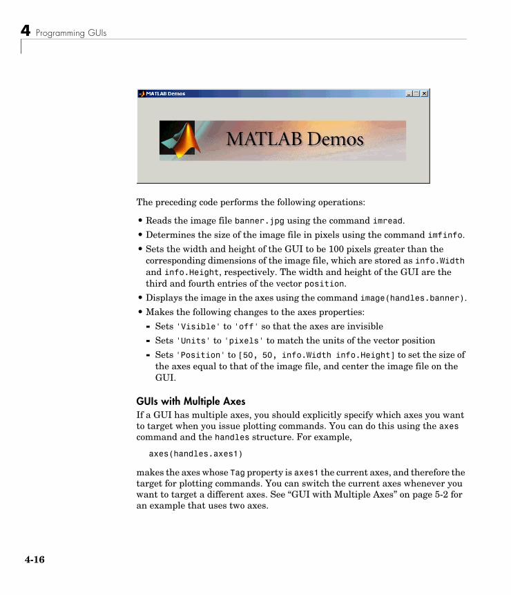
4 Programming GUIs
4-16
The preceding code performs the following operations:
• Reads the image file banner.jpg using the command imread.
• Determines the size of the image file in pixels using the command imfinfo.
• Sets the width and height of the GUI to be 100 pixels greater than the corresponding dimensions of the image file, which are stored as info.Width and info.Height, respectively. The width and height of the GUI are the third and fourth entries of the vector position.
• Displays the image in the axes using the command image(handles.banner).
• Makes the following changes to the axes properties:
- Sets 'Visible' to 'off' so that the axes are invisible
- Sets 'Units' to 'pixels' to match the units of the vector position
- Sets 'Position' to [50, 50, info.Width info.Height] to set the size of the axes equal to that of the image file, and center the image file on the GUI.
GUIs with Multiple AxesIf a GUI has multiple axes, you should explicitly specify which axes you want to target when you issue plotting commands. You can do this using the axes command and the handles structure. For example,
axes(handles.axes1)
makes the axes whose Tag property is axes1 the current axes, and therefore the target for plotting commands. You can switch the current axes whenever you want to target a different axes. See “GUI with Multiple Axes” on page 5-2 for an example that uses two axes.
Programming Callbacks for GUI Components
4-17
ActiveX ControlsYou can insert an ActiveX control into your GUI if you are running MATLAB on Microsoft Windows. When you drag an ActiveX component from the component palette into the layout area, GUIDE displays a dialog in which you can select any registered ActiveX control on your system. When you select an ActiveX control and click Create, the control appears as a small box in the Layout Editor. You can then program the control to do what you want it to.
See MATLAB COM Client Support in the online MATLAB documentation to learn more about ActiveX controls.
This section covers the following topics:
• “Adding an ActiveX Control to a GUI” on page 4-17
• “Viewing the ActiveX Properties with the Property Inspector” on page 4-19
• “Adding a Callback to an ActiveX Control to Change a Property” on page 4-20
• “Adding a Uicontrol to Change an ActiveX Control Property” on page 4-21
• “Viewing the Methods for an ActiveX Control” on page 4-23
• “Saving a GUI that Contains an ActiveX Control” on page 4-24
• “Compiling a GUI that Contains an ActiveX Control” on page 4-25
Adding an ActiveX Control to a GUIThis section shows how to add an ActiveX control to a GUI. The section describes a simple ActiveX control that displays a circle. After adding the ActiveX control, you can program the GUI to change the radius of the circle and display the new value of the radius.
Note If MATLAB is not installed locally on your computer — for example, if you are running MATLAB over a network — you might not find the ActiveX control described in this example. To register the control, see Registering Controls and Servers in the online MATLAB documentation.
To make the example,
1 Open a new GUI in GUIDE and drag an ActiveX control from the component palette into the Layout Editor.
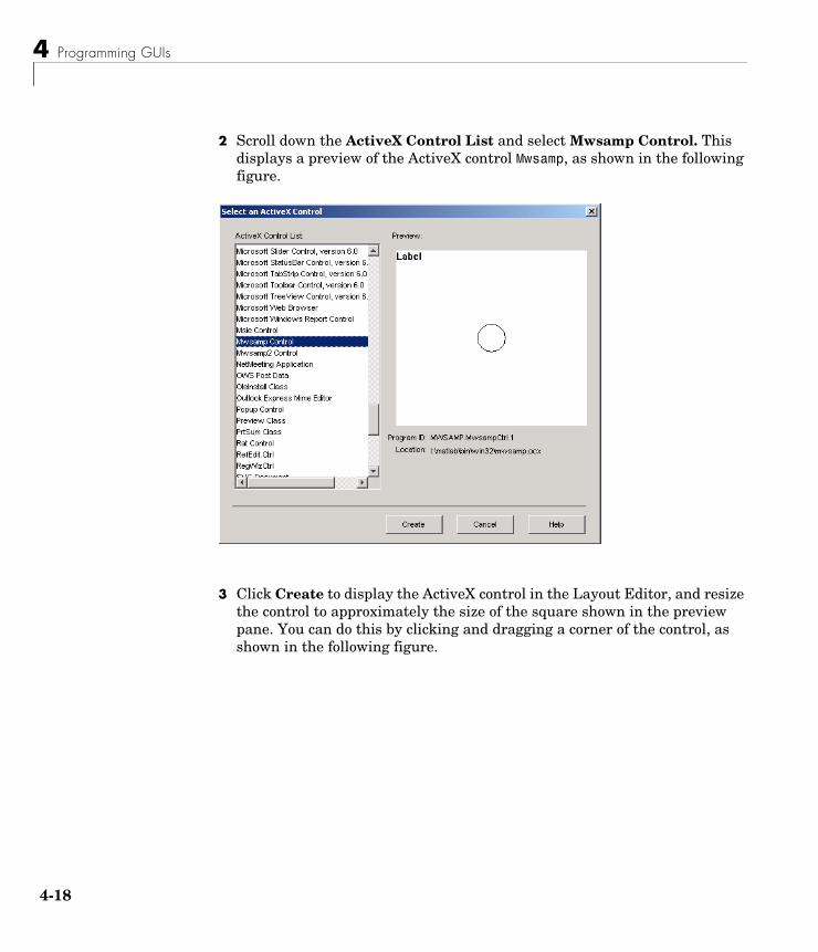
4 Programming GUIs
4-18
2 Scroll down the ActiveX Control List and select Mwsamp Control. This displays a preview of the ActiveX control Mwsamp, as shown in the following figure.
3 Click Create to display the ActiveX control in the Layout Editor, and resize the control to approximately the size of the square shown in the preview pane. You can do this by clicking and dragging a corner of the control, as shown in the following figure.
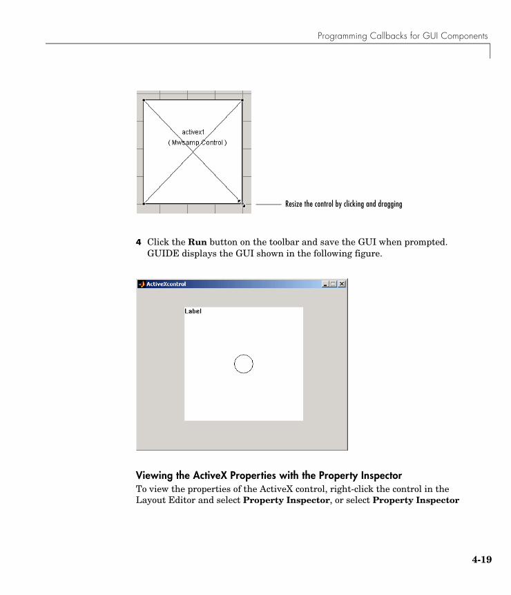
Programming Callbacks for GUI Components
4-19
4 Click the Run button on the toolbar and save the GUI when prompted. GUIDE displays the GUI shown in the following figure.
Viewing the ActiveX Properties with the Property InspectorTo view the properties of the ActiveX control, right-click the control in the Layout Editor and select Property Inspector, or select Property Inspector
Resize the control by clicking and dragging
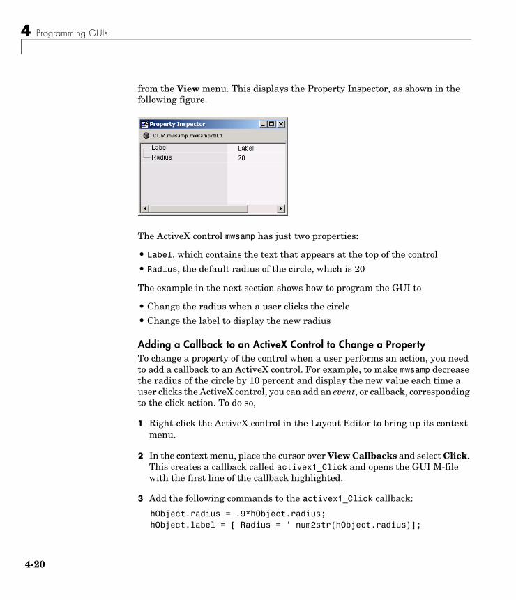
4 Programming GUIs
4-20
from the View menu. This displays the Property Inspector, as shown in the following figure.
The ActiveX control mwsamp has just two properties:
• Label, which contains the text that appears at the top of the control
• Radius, the default radius of the circle, which is 20
The example in the next section shows how to program the GUI to
• Change the radius when a user clicks the circle
• Change the label to display the new radius
Adding a Callback to an ActiveX Control to Change a Property To change a property of the control when a user performs an action, you need to add a callback to an ActiveX control. For example, to make mwsamp decrease the radius of the circle by 10 percent and display the new value each time a user clicks the ActiveX control, you can add an event, or callback, corresponding to the click action. To do so,
1 Right-click the ActiveX control in the Layout Editor to bring up its context menu.
2 In the context menu, place the cursor over View Callbacks and select Click. This creates a callback called activex1_Click and opens the GUI M-file with the first line of the callback highlighted.
3 Add the following commands to the activex1_Click callback:
hObject.radius = .9*hObject.radius;hObject.label = ['Radius = ' num2str(hObject.radius)];
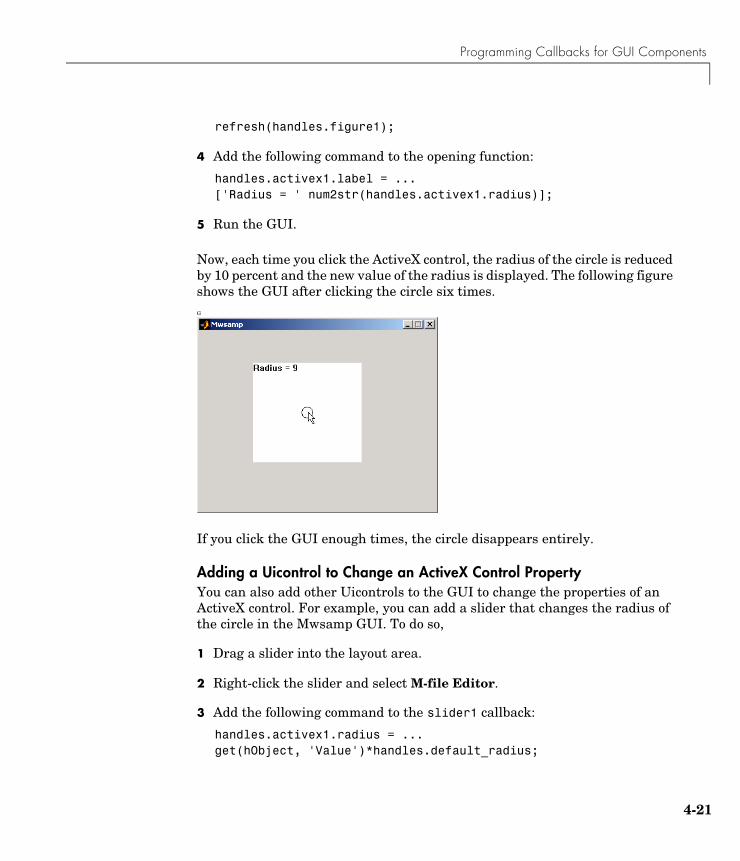
Programming Callbacks for GUI Components
4-21
refresh(handles.figure1);
4 Add the following command to the opening function:
handles.activex1.label = ...['Radius = ' num2str(handles.activex1.radius)];
5 Run the GUI.
Now, each time you click the ActiveX control, the radius of the circle is reduced by 10 percent and the new value of the radius is displayed. The following figure shows the GUI after clicking the circle six times.G
If you click the GUI enough times, the circle disappears entirely.
Adding a Uicontrol to Change an ActiveX Control PropertyYou can also add other Uicontrols to the GUI to change the properties of an ActiveX control. For example, you can add a slider that changes the radius of the circle in the Mwsamp GUI. To do so,
1 Drag a slider into the layout area.
2 Right-click the slider and select M-file Editor.
3 Add the following command to the slider1 callback:
handles.activex1.radius = ...get(hObject, 'Value')*handles.default_radius;
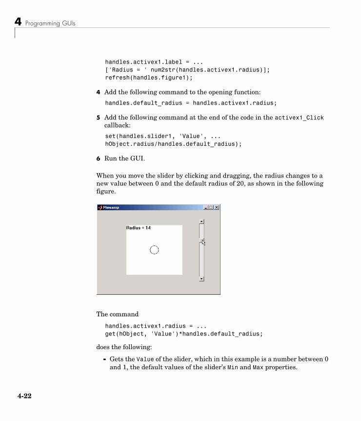
4 Programming GUIs
4-22
handles.activex1.label = ...['Radius = ' num2str(handles.activex1.radius)];refresh(handles.figure1);
4 Add the following command to the opening function:
handles.default_radius = handles.activex1.radius;
5 Add the following command at the end of the code in the activex1_Click callback:
set(handles.slider1, 'Value', ... hObject.radius/handles.default_radius);
6 Run the GUI.
When you move the slider by clicking and dragging, the radius changes to a new value between 0 and the default radius of 20, as shown in the following figure.
The command
handles.activex1.radius = ...get(hObject, 'Value')*handles.default_radius;
does the following:
- Gets the Value of the slider, which in this example is a number between 0 and 1, the default values of the slider’s Min and Max properties.
Programming Callbacks for GUI Components
4-23
- Sets handles.activex1.radius equal to the Value times the default radius.
Note that clicking the ActiveX control causes the slider to change position corresponding to the new value of the radius. The command
set(handles.slider1, 'Value', ... hObject.radius/handles.default_radius);
in the activex1_Click callback resets the slider’s Value each time the user clicks the ActiveX control.
Viewing the Methods for an ActiveX ControlTo view the available methods for the ActiveX control, you first need to obtain the handle to the control. One way to do this is the following:
1 In the GUI M-file, add the command keyboard on a separate line of the activex1_Click callback. The command keyboard puts MATLAB in debug mode and pauses at the activex1_Click callback when you click the ActiveX control.
2 Run the GUI and click the ActiveX control.
The handle to the control is now set to hObject. To view the methods for the control, enter
methodsview(hObject)
at the MATLAB prompt. This displays the available methods in a new window, as shown in the following figure.
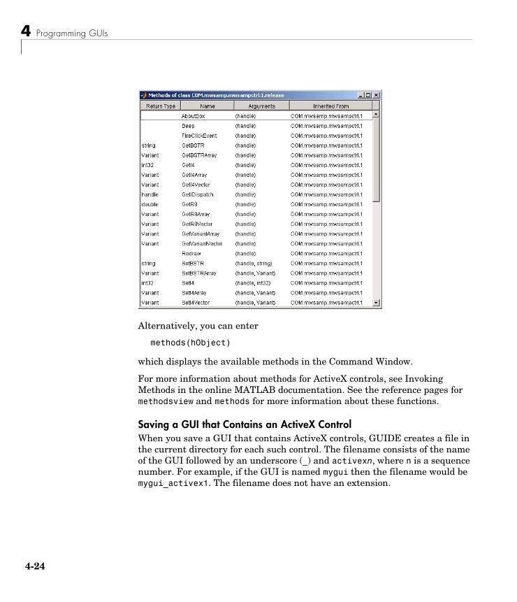
4 Programming GUIs
4-24
Alternatively, you can enter
methods(hObject)
which displays the available methods in the Command Window.
For more information about methods for ActiveX controls, see Invoking Methods in the online MATLAB documentation. See the reference pages for methodsview and methods for more information about these functions.
Saving a GUI that Contains an ActiveX Control When you save a GUI that contains ActiveX controls, GUIDE creates a file in the current directory for each such control. The filename consists of the name of the GUI followed by an underscore (_) and activexn, where n is a sequence number. For example, if the GUI is named mygui then the filename would be mygui_activex1. The filename does not have an extension.
Programming Callbacks for GUI Components
4-25
Compiling a GUI that Contains an ActiveX ControlIf you use the MATLAB Compiler mcc command to compile a GUI that contains an ActiveX control, you must use the -a flag to add the ActiveX file, which GUIDE saves in the current directory, to the CTF archive. Your command should be similar to this
mcc -m mygui -a mygui_activex1
where mygui_activex1 is the name of the ActiveX file. See the MATLAB Compiler documentation for more information. If you have more than one such file, use a separate -a flag for each file. You must have installed the MATLAB Compiler to compile a GUI.
FiguresFigures are the windows that contain the GUIs you design with the Layout Editor. See the Figure Properties reference page for information on what figure characteristics you can control.
Displaying Plots in a Separate FigureTo prevent a figure from becoming the target of plotting commands issued at the command line or by other GUIs, you can set the HandleVisibility and IntegerHandle properties to off. However, this means the figure is also hidden from plotting commands issued by your GUI. To issue plotting commands from your GUI,
• Create a figure and axes.
• Save the handle of the figure in the handles structure.
• Create an axes, save its handle, and set its Parent property to the figure handle.
• Create the plot, save the handles, and set their Parent properties to the handle of the axes.
The following code illustrates these steps:
fHandle = figure('HandleVisibility','off','IntegerHandle','off',... 'Visible','off');aHandle = axes('Parent',fHandle);pHandles = plot(PlotData,'Parent',aHandle);
4 Programming GUIs
4-26
set(fHandle,'Visible','on')
Note that not all plotting commands accept property name/property value specifications as arguments. Consult the reference page for the specific command to see what arguments you can specify.
Managing GUI Data with the Handles Structure
4-27
Managing GUI Data with the Handles Structure
Note GUI data is application-defined data that is saved and retrieved using the guidata function. GUIDE uses guidata to manage the handles structure.
GUIDE provides a mechanism, called the handles structure, for storing and retrieving shared data using the same structure that contains the GUI component handles.
This structure, which initially contains only the handles of the components in the GUI, is passed to the handles argument of each callback in the GUI M-file. Because this structure is passed to all callbacks for the GUI, any data you add to it become available to all the callbacks. The following example illustrates this technique.
If you are not familiar with MATLAB structures, see Structures for more information.
Example: Passing Data Between CallbacksThis example demonstrates how to use the handles structure to pass data between callbacks. The example passes data between a slider and an editable text box in the following way:
• When a user moves the slider, the text box displays the slider’s current value.
• When a user types a value into the text box, the slider updates to this value.
• If a user enters a value in the text box that is out of range for the slider — that is, a value that is not between 0 and 1 — the application returns a message indicating how many times the user has entered an erroneous value.
The following figure shows the GUI with a static text field above the edit text box.
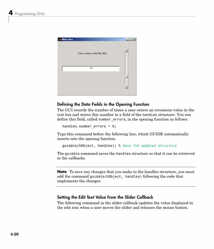
4 Programming GUIs
4-28
Defining the Data Fields in the Opening FunctionThe GUI records the number of times a user enters an erroneous value in the text box and stores this number in a field of the handles structure. You can define this field, called number_errors, in the opening function as follows:
handles.number_errors = 0;
Type this command before the following line, which GUIDE automatically inserts into the opening function.
guidata(hObject, handles); % Save the updated structure
The guidata command saves the handles structure so that it can be retrieved in the callbacks.
Note To save any changes that you make to the handles structure, you must add the command guidata(hObject, handles) following the code that implements the changes.
Setting the Edit Text Value from the Slider CallbackThe following command in the slider callback updates the value displayed in the edit text when a user moves the slider and releases the mouse button.
Managing GUI Data with the Handles Structure
4-29
set(handles.edit1,'String',... num2str(get(handles.slider1,'Value')));
The code combines three commands:
• The get command obtains the current value of the slider.
• The num2str command converts the value to a string.
• The set command resets the String property of the edit text to the updated value.
Setting the Slider Value from the Edit Text CallbackThe edit text callback sets the slider’s value to the number the user types in, after checking to see if it is a single numeric value between 0 and 1. If the value is out of range, then the error count is incremented and the edit text displays a message telling the user how many times they have entered an invalid number.
val = str2double(get(handles.edit1,'String'));% Determine whether val is a number between 0 and 1if isnumeric(val) & length(val)==1 & ...
val >= get(handles.slider1,'Min') & ...val <= get(handles.slider1,'Max')set(handles.slider1,'Value',val);
else% Increment the error count, and display it
handles.number_errors = handles.number_errors+1;guidata(hObject,handles); % store the changesset(handles.edit1,'String',...['You have entered an invalid entry ',...
num2str(handles.number_errors),' times.']);end
If the user types a number between 0 and 1 in the edit box and then clicks outside the edit box, the callback sets handles.slider1 to the new value and the slider moves to the corresponding position.
If the entry is invalid — for example, 2.5 — the GUI increments the value of handles.number_errors and displays a message like the following:

4 Programming GUIs
4-30
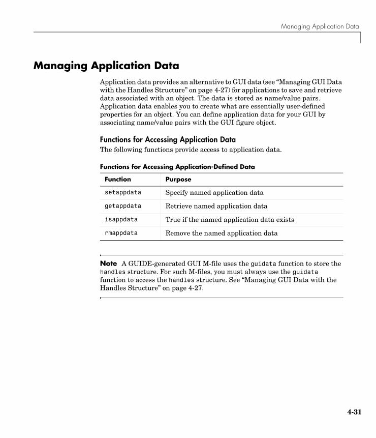
Managing Application Data
4-31
Managing Application DataApplication data provides an alternative to GUI data (see “Managing GUI Data with the Handles Structure” on page 4-27) for applications to save and retrieve data associated with an object. The data is stored as name/value pairs. Application data enables you to create what are essentially user-defined properties for an object. You can define application data for your GUI by associating name/value pairs with the GUI figure object.
Functions for Accessing Application DataThe following functions provide access to application data.
Note A GUIDE-generated GUI M-file uses the guidata function to store the handles structure. For such M-files, you must always use the guidata function to access the handles structure. See “Managing GUI Data with the Handles Structure” on page 4-27.
Functions for Accessing Application-Defined Data
Function Purpose
setappdata Specify named application data
getappdata Retrieve named application data
isappdata True if the named application data exists
rmappdata Remove the named application data
4 Programming GUIs
4-32
Designing for Cross-Platform CompatibilityYou can use specific property settings to create a GUI that behaves more consistently when run on different platforms:
• Use the default font (uicontrol FontName property).
• Use the default background color (uicontrol BackgroundColor property).
• Use figure character units (figure Units property).
Using the Default System FontBy default, uicontrols use the default font for the platform on which they are running. For example, when displaying your GUI on PCs, uicontrols uses MS San Serif. When your GUI runs on a different platform, it uses that computer’s default font. This provides a consistent look with respect to your GUI and other application GUIs.
If you have set the FontName property to a named font and want to return to the default value, you can set the property to the string default. This ensures that MATLAB uses the system default at runtime.
From within the GUI M-file, use the set command. For example, if there is a push button in your GUI and its handle is stored in the pushbutton1 field of the handles structure, then the statement,
set(handles.pushbutton1,'FontName','default')
sets the FontName property to use the system default. You can also use the Property Inspector to set this property:
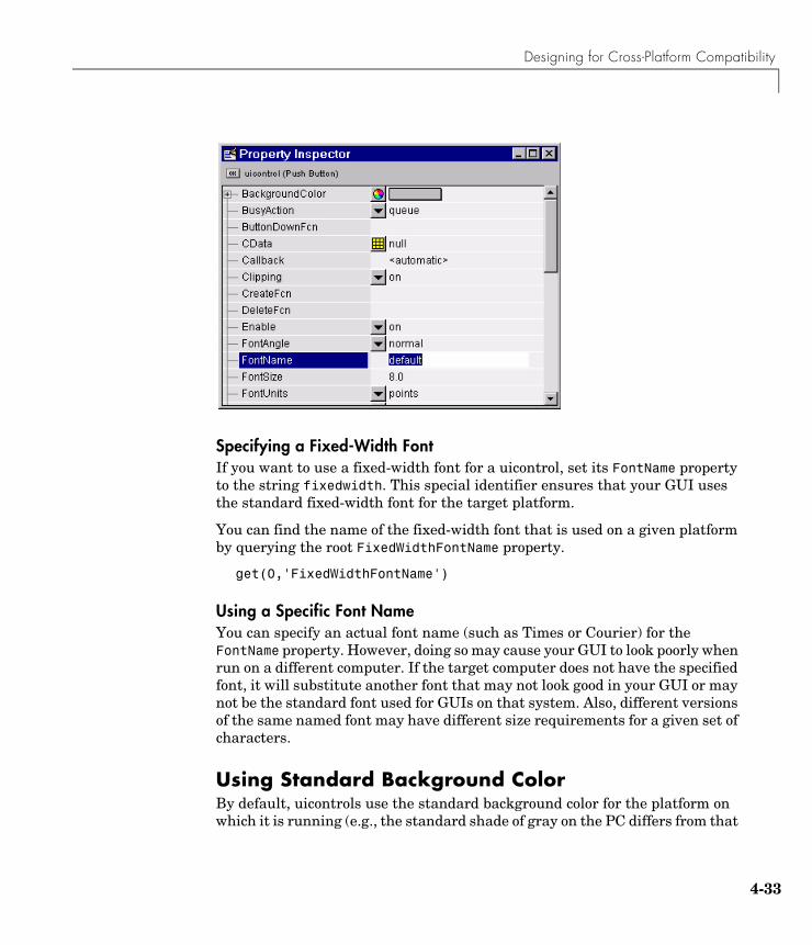
Designing for Cross-Platform Compatibility
4-33
Specifying a Fixed-Width FontIf you want to use a fixed-width font for a uicontrol, set its FontName property to the string fixedwidth. This special identifier ensures that your GUI uses the standard fixed-width font for the target platform.
You can find the name of the fixed-width font that is used on a given platform by querying the root FixedWidthFontName property.
get(0,'FixedWidthFontName')
Using a Specific Font NameYou can specify an actual font name (such as Times or Courier) for the FontName property. However, doing so may cause your GUI to look poorly when run on a different computer. If the target computer does not have the specified font, it will substitute another font that may not look good in your GUI or may not be the standard font used for GUIs on that system. Also, different versions of the same named font may have different size requirements for a given set of characters.
Using Standard Background ColorBy default, uicontrols use the standard background color for the platform on which it is running (e.g., the standard shade of gray on the PC differs from that
4 Programming GUIs
4-34
on UNIX). When your GUI is deployed on a different platform, it uses that computer’s standard color. This provides a consistent look with respect to your GUI and other application GUIs.
If you change the BackgroundColor to another value, MATLAB always uses the specified color.
Cross-Platform Compatible Figure UnitsCross-platform compatible GUIs should look correct on computers having different screen sizes and resolutions. Since the size of a pixel can vary on different computer displays, using the default figure Units of pixels does not produce a GUI that looks the same on all platforms.
For this reason, GUIDE sets the figure Units property to characters.
System-Dependent UnitsFigure character units are defined by characters from the default system font; one character unit equals the width of the letter x in the system font. The height of one character is the distance between the baselines of two lines of text (note that character units are not square).
GUIDE sets the figure Units property to characters so that your GUIs automatically adjust the size and relative spacing of components as the GUI displays on different computers. For example, if the size of the text label on a component becomes larger because of different system font metrics, then the component size and the relative spacing between components increases proportionally.
Types of Callbacks
4-35
Types of CallbacksThe primary mechanism for implementing a GUI is programming the callbacks of the GUI components used to build the interface.
Callback Properties for All Graphics ObjectsAll graphics objects have three properties that enable you to define callback routines:
• ButtonDownFcn — MATLAB executes this callback when users click the left mouse button and the cursor is over the object or within a five-pixel border around the object. See “Which Callback Executes” for information specific to uicontrols
• CreateFcn — MATLAB executes this callback when creating the object.
• DeleteFcn — MATLAB executes this callback just before deleting the object.
Callback Properties for FiguresFigures have additional properties that execute callback routines with the appropriate user action. Only the CloseRequestFcn has a callback defined by default:
• CloseRequestFcn — MATLAB executes the specified callback when a request is made to close the figure (by a close command, by the window manager menu, or by quitting MATLAB).
• KeyPressFcn — MATLAB executes the specified callback when users press a key and the cursor is within the figure window and no component has focus.
• ResizeFcn — MATLAB executes the specified callback routine when users resize the figure window.
• WindowButtonDownFcn — MATLAB executes the specified callback when users click the mouse button and the cursor is within the figure, but not over an enabled uicontrol.
• WindowButtonMotionFcn — MATLAB executes the specified callback when users move the mouse button within the figure window.
• WindowButtonUpFcn — MATLAB executes the specified callback when users release the mouse button, after having pressed the mouse button within the figure.
4 Programming GUIs
4-36
Callbacks for Specific ComponentsSome components have additional properties that execute callback routines with the appropriate user action:
• Callback — MATLAB executes the specified callback when a user activates a user interface control (uicontrol) or menu (uimenu) object, for example, when a user presses a push button or selects a menu item.
• KeyPressFcn — MATLAB executes the specified callback when a user presses a key and the callback’s component has focus.
• ResizeFcn — MATLAB executes the specified callback routine when users resize a panel (uipanel) or button group (uibuttongroup) object.
• SelectionChangeFcn — MATLAB executes the specified callback routine when a user selects a different radio button or toggle button in a button group component.
Which Callback ExecutesClicking on an enabled uicontrol prevents any ButtonDownFcn and WindowButtonDownFcn callbacks from executing. If you click on an inactive uicontrol, figure, or other graphics objects having callbacks defined, MATLAB first executes the WindownButtonDownFcn of the figure (if defined) and then the ButtonDownFcn of the object targeted by the mouse click.
Adding a CallbackTo add a callback subfunction to the GUI M-file, click the right mouse button while the object is selected to display the Layout Editor context menu. Select the desired callback from the context menu and GUIDE adds the subfunction stub to the GUI M-file.
Interrupting Executing Callbacks
4-37
Interrupting Executing CallbacksBy default, MATLAB allows an executing callback to be interrupted by subsequently invoked callbacks. For example, suppose you have created a dialog box that displays a progress indicator while loading data. This dialog could have a “Cancel” button that stops the loading operation. The “Cancel” button’s callback routine would interrupt the currently executing callback routine.
But, there are cases where you may not want user actions to interrupt an executing callback. For example, a data analysis tool may need to perform lengthy calculations before updating a graph. An impatient user may inadvertently click the mouse on other components and thereby interrupt the calculations while in progress. This could change the MATLAB state before returning to the original callback.
The following sections provide more information on this topic:
• “Controlling Interruptibility”
• “The Event Queue”
• “Event Processing During Callback Execution”
Controlling InterruptibilityAll graphics objects have an Interruptible property that determines whether their callbacks can be interrupted. The default value is on, which means that callbacks can be interrupted. However, MATLAB checks the event queue only when it encounters certain commands — drawnow, figure, getframe, pause, and, waitfor. Otherwise, the callback continues to completion.
The Event QueueMATLAB commands that perform calculations or assign values to properties execute as they are encountered in the callback. However, commands or actions that affect the state of the figure window generate events that are placed in a queue. Events are caused by any command that causes the figure to be redrawn or any user action, such as a button click or cursor movement, for which there is a callback routine defined.
MATLAB processes the event queue only when the callback finishes execution or when the callback contains the following commands:
4 Programming GUIs
4-38
• drawnow
• figure • getframe• pause• waitfor
When MATLAB encounters one of these commands in a callback, it suspends execution and processes the events in the event queue. The way MATLAB handles an event depends on the event type and the setting of the callback object’s Interruptible property:
• Events that would cause another callback to execute (e.g., clicking a push button or figure window mouse button actions) can execute the callback only if the current callback object’s Interruptible property is on.
• Events that cause the figure window to redraw execute the redraw regardless of the value of the current callback object’s Interruptible property.
Note that callbacks defined for an object’s DeleteFcn or CreateFcn or a figure’s CloseRequestFcn or ResizeFcn interrupt an executing callback regardless of the value of the object’s Interruptible property.
What Happens to Events That Are Blocked — BusyAction PropertyAll objects have a BusyAction property that determines what happens to their events when processed during noninterruptible callback routine execution.
BusyAction has two possible values:
• queue — Keep the event in the event queue and process it after the noninterruptible callback finishes.
• cancel — Discard the event and remove it from the event queue.
Event Processing During Callback ExecutionThe following sequence describes how MATLAB processes events while a callback executes:
1 If MATLAB encounters a drawnow, figure, getframe, pause, or waitfor command in the callback routine, MATLAB suspends execution and begins processing the event queue.
Interrupting Executing Callbacks
4-39
2 If the event at the top of the queue calls for a figure window redraw, MATLAB performs the redraw and proceeds to the next event in the queue.
3 If the event at the top of the queue would cause a callback to execute, MATLAB determines whether the object whose callback is suspended is interruptible.
4 If the callback is interruptible, MATLAB executes the callback associated with the interrupting event. If that callback contains a drawnow, figure, getframe, pause, or waitfor command, MATLAB repeats these steps for the remaining events in the queue.
5 If the callback is not interruptible, MATLAB checks the BusyAction property of the object that generated the event.
a If BusyAction is queue, MATLAB leaves the event in the event queue.
b If BusyAction is cancel, MATLAB discards the event.
6 When all events have been processed (either left in the queue, discarded, or handled as a redraw), MATLAB resumes execution of the interrupted callback routine.
This process continues until the callback completes execution. When MATLAB returns the prompt to the command window, all events have been processed.
4 Programming GUIs
4-40
Controlling Figure Window BehaviorWhen designing a GUI you need to consider how you want the figure window to behave. The appropriate behavior for a particular GUI depends on intended use. Consider the following examples:
• A GUI that implements tools for annotating graphs is usually designed to be available while the user performs other MATLAB tasks. Perhaps this tool operates on only one figure at a time so you need a new instance of this tool for each graph.
• A dialog that requires an answer to a question may need to block MATLAB execution until the user answers the question. However, the user may need to look at other MATLAB windows to obtain information needed to answer the question. The dialog is blocking.
• A dialog that warns users that the specified operation will delete files so you want to force the user to respond to the warning before performing any other action. In this case, the dialog is both blocking and modal.
The following techniques are useful for handling these GUI design issues:
• Allow single or multiple instances of the GUI at any one time.
• Use modal figure windows that allow users to interact only with the GUI.
Using Modal Figure WindowsModal windows trap all keyboard and mouse events that occur in any visible MATLAB window. This means a modal GUI figure can process the user interactions with any of its components, but does not allow the user to access any other MATLAB window (including the command window). In addition, a modal window remains stacked on top of other MATLAB windows until it is deleted, at which time focus returns to the window that last had focus. See the figure WindowStyle property for more details.
Use modal figures when you want to force users to respond to your GUI before allowing them to take other actions in MATLAB.
Making a Figure ModalSet the figure’s WindowStyle property to modal to make the window modal. You can use the Property Inspector to change this property or add a statement in
Controlling Figure Window Behavior
4-41
the initialization section of the GUI M-file in the opening function with the set command.
set(hObject,'WindowStyle','modal')
Dismissing a Modal FigureA GUI using a modal figure must take one of the following actions in a callback routine to release control:
• Delete the figure.delete(handles.figure1)
• Make the figure invisible. set(handles.figure1,'Visible','off')
• Change the figure’s WindowStyle property to normal. set(handles.figure1,'WindowStyle','normal')
The user can also type Ctrl+C in a modal figure to convert it to a normal window.
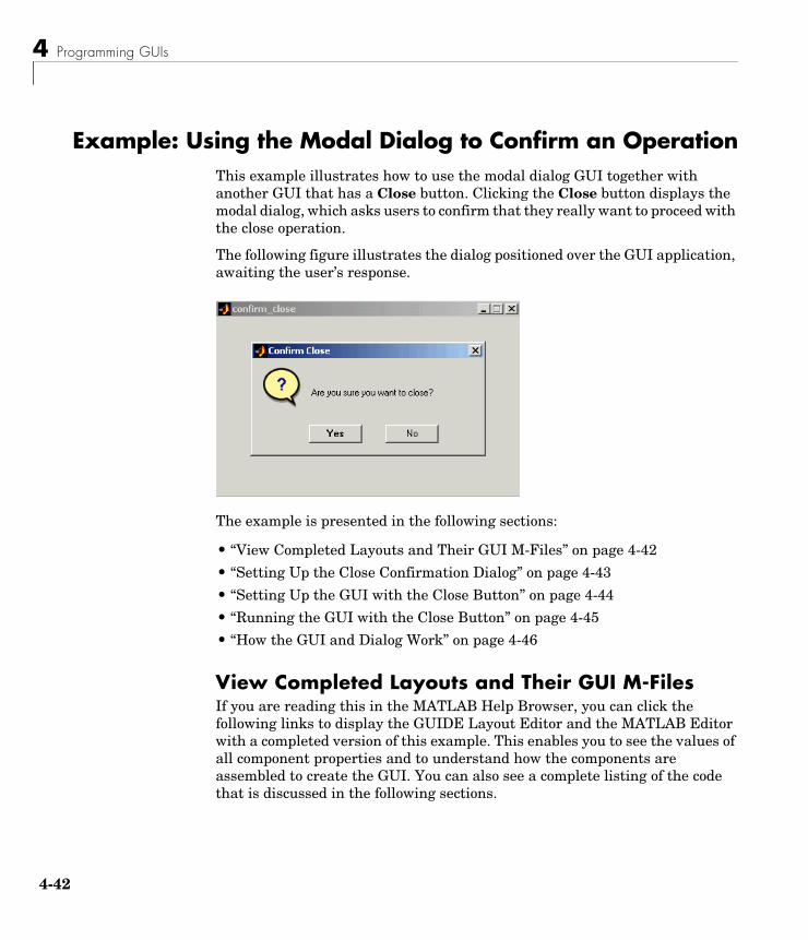
4 Programming GUIs
4-42
Example: Using the Modal Dialog to Confirm an OperationThis example illustrates how to use the modal dialog GUI together with another GUI that has a Close button. Clicking the Close button displays the modal dialog, which asks users to confirm that they really want to proceed with the close operation.
The following figure illustrates the dialog positioned over the GUI application, awaiting the user’s response.
The example is presented in the following sections:
• “View Completed Layouts and Their GUI M-Files” on page 4-42
• “Setting Up the Close Confirmation Dialog” on page 4-43
• “Setting Up the GUI with the Close Button” on page 4-44
• “Running the GUI with the Close Button” on page 4-45
• “How the GUI and Dialog Work” on page 4-46
View Completed Layouts and Their GUI M-FilesIf you are reading this in the MATLAB Help Browser, you can click the following links to display the GUIDE Layout Editor and the MATLAB Editor with a completed version of this example. This enables you to see the values of all component properties and to understand how the components are assembled to create the GUI. You can also see a complete listing of the code that is discussed in the following sections.
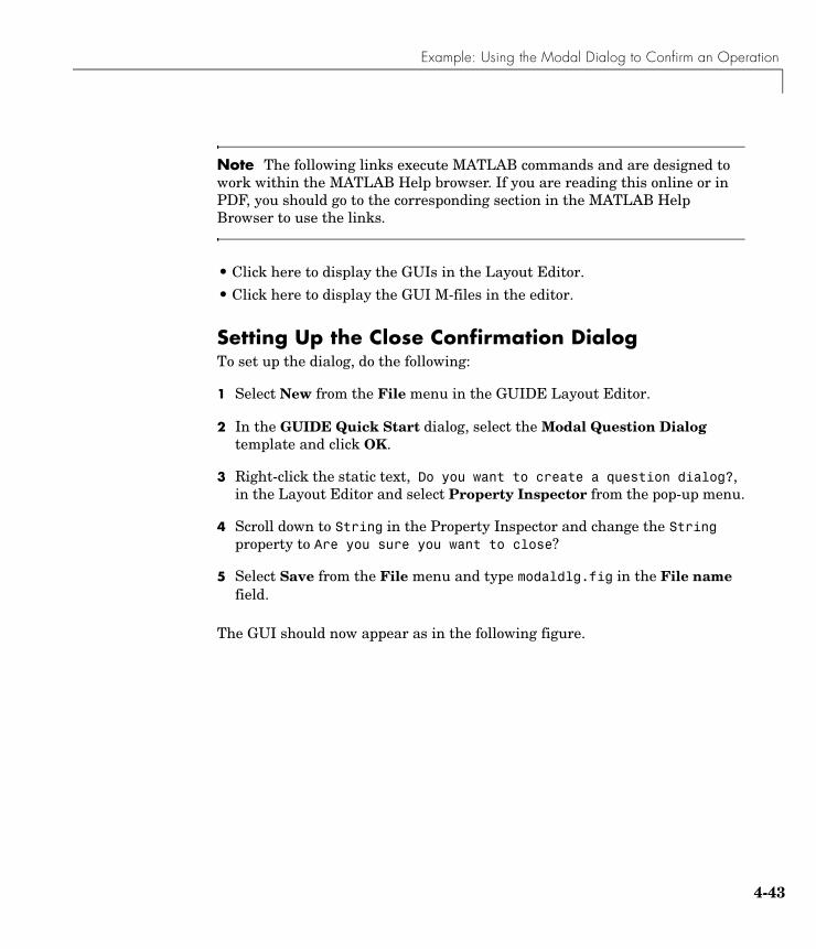
Example: Using the Modal Dialog to Confirm an Operation
4-43
Note The following links execute MATLAB commands and are designed to work within the MATLAB Help browser. If you are reading this online or in PDF, you should go to the corresponding section in the MATLAB Help Browser to use the links.
• Click here to display the GUIs in the Layout Editor.
• Click here to display the GUI M-files in the editor.
Setting Up the Close Confirmation DialogTo set up the dialog, do the following:
1 Select New from the File menu in the GUIDE Layout Editor.
2 In the GUIDE Quick Start dialog, select the Modal Question Dialog template and click OK.
3 Right-click the static text, Do you want to create a question dialog?, in the Layout Editor and select Property Inspector from the pop-up menu.
4 Scroll down to String in the Property Inspector and change the String property to Are you sure you want to close?
5 Select Save from the File menu and type modaldlg.fig in the File name field.
The GUI should now appear as in the following figure.
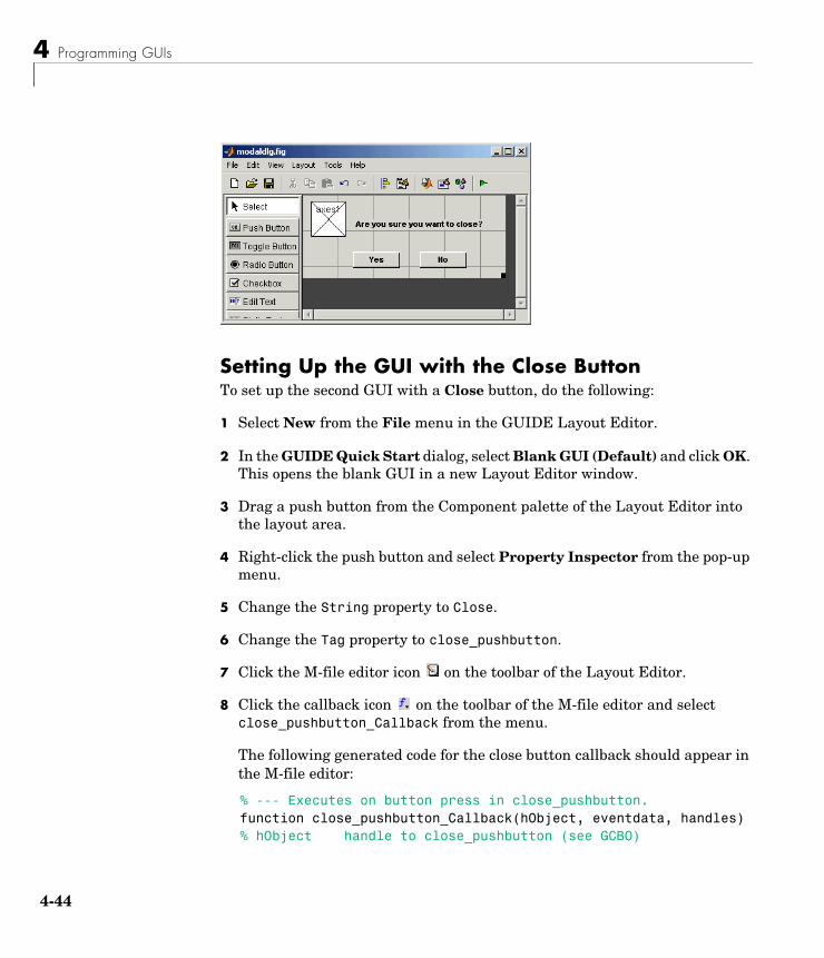
4 Programming GUIs
4-44
Setting Up the GUI with the Close ButtonTo set up the second GUI with a Close button, do the following:
1 Select New from the File menu in the GUIDE Layout Editor.
2 In the GUIDE Quick Start dialog, select Blank GUI (Default) and click OK. This opens the blank GUI in a new Layout Editor window.
3 Drag a push button from the Component palette of the Layout Editor into the layout area.
4 Right-click the push button and select Property Inspector from the pop-up menu.
5 Change the String property to Close.
6 Change the Tag property to close_pushbutton.
7 Click the M-file editor icon on the toolbar of the Layout Editor.
8 Click the callback icon on the toolbar of the M-file editor and select close_pushbutton_Callback from the menu.
The following generated code for the close button callback should appear in the M-file editor:
% --- Executes on button press in close_pushbutton.function close_pushbutton_Callback(hObject, eventdata, handles)% hObject handle to close_pushbutton (see GCBO)
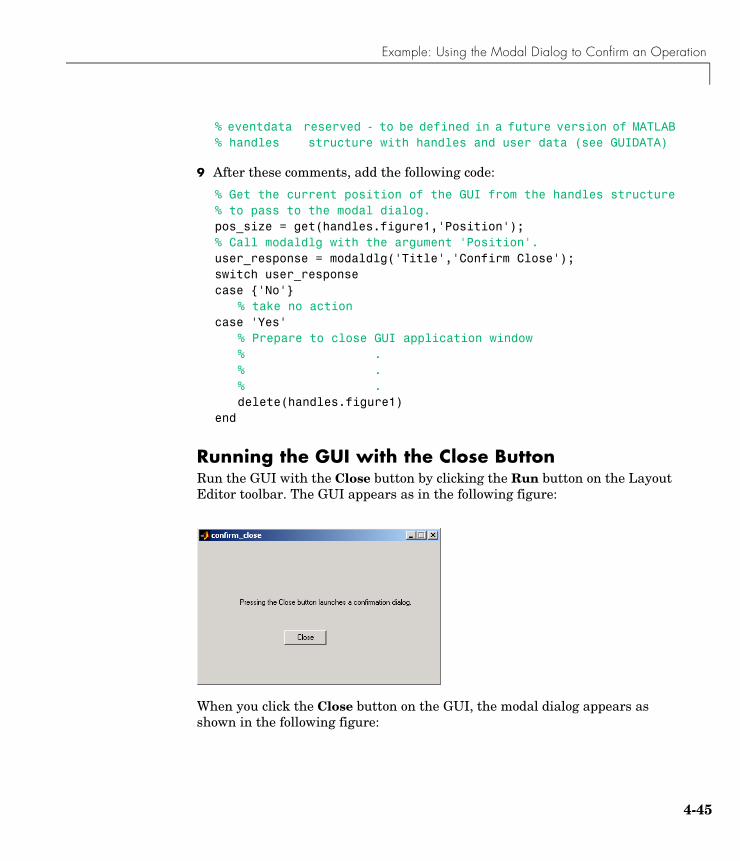
Example: Using the Modal Dialog to Confirm an Operation
4-45
% eventdata reserved - to be defined in a future version of MATLAB% handles structure with handles and user data (see GUIDATA)
9 After these comments, add the following code:
% Get the current position of the GUI from the handles structure% to pass to the modal dialog.pos_size = get(handles.figure1,'Position');% Call modaldlg with the argument 'Position'.user_response = modaldlg('Title','Confirm Close');switch user_responsecase {'No'}
% take no actioncase 'Yes'
% Prepare to close GUI application window% .% .% .delete(handles.figure1)
end
Running the GUI with the Close ButtonRun the GUI with the Close button by clicking the Run button on the Layout Editor toolbar. The GUI appears as in the following figure:
When you click the Close button on the GUI, the modal dialog appears as shown in the following figure:
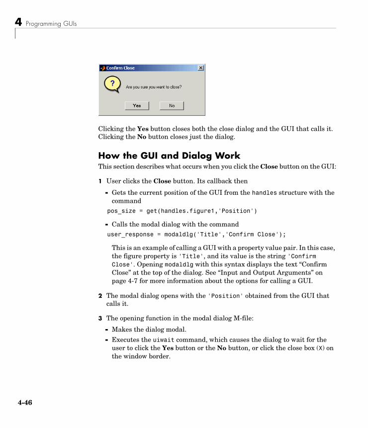
4 Programming GUIs
4-46
Clicking the Yes button closes both the close dialog and the GUI that calls it. Clicking the No button closes just the dialog.
How the GUI and Dialog WorkThis section describes what occurs when you click the Close button on the GUI:
1 User clicks the Close button. Its callback then
- Gets the current position of the GUI from the handles structure with the command
pos_size = get(handles.figure1,'Position')
- Calls the modal dialog with the command user_response = modaldlg('Title','Confirm Close');
This is an example of calling a GUI with a property value pair. In this case, the figure property is 'Title', and its value is the string 'Confirm Close'. Opening modaldlg with this syntax displays the text “Confirm Close” at the top of the dialog. See “Input and Output Arguments” on page 4-7 for more information about the options for calling a GUI.
2 The modal dialog opens with the 'Position' obtained from the GUI that calls it.
3 The opening function in the modal dialog M-file:
- Makes the dialog modal.
- Executes the uiwait command, which causes the dialog to wait for the user to click the Yes button or the No button, or click the close box (X) on the window border.
Example: Using the Modal Dialog to Confirm an Operation
4-47
4 When a user clicks one of the two push buttons, the callback for the push button
- Updates the output field in the handles structure
- Executes uiresume to return control to the opening function where uiwait is called.
5 The output function is called, which returns the string Yes or No as an output argument, and deletes the dialog with the command
delete(handles.figure1)
6 When the GUI with the Close button regains control, it receives the string Yes or No. If the answer is 'No', it does nothing. If the answer is 'Yes', the close button callback closes the GUI with the command
delete(handles.figure1)

4 Programming GUIs
4-48
5
GUI Applications
GUI with Multiple Axes (p. 5-2) Analyze data and generate frequency and time domain plots in the GUI figure.
List Box Directory Reader (p. 5-9) List the contents of a directory, navigate to other directories, and define what command to execute when users double-click on a given type of file.
Accessing Workspace Variables from a List Box (p. 5-15)
List variables in the base MATLAB workspace from a GUI and plot them. This example illustrates selecting multiple items and executing commands in a different workspace.
A GUI to Set Simulink Model Parameters (p. 5-19)
Set parameters in a Simulink® model, save and plot the data, and implement a help button.
An Address Book Reader (p. 5-31) Read data from MAT-files, edit and save the data, and manage GUI data using the handles structure.
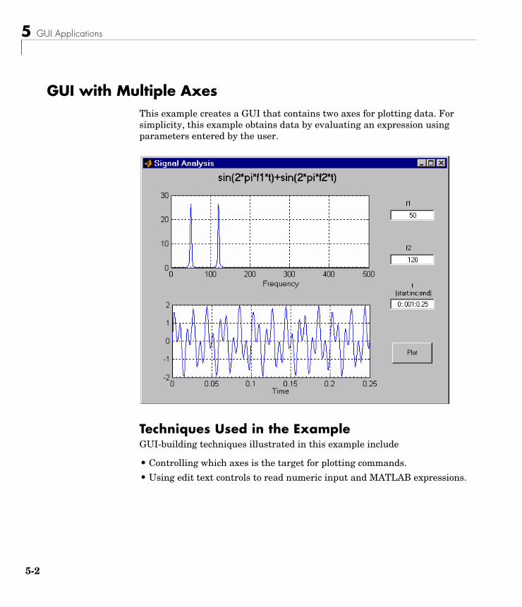
5 GUI Applications
5-2
GUI with Multiple AxesThis example creates a GUI that contains two axes for plotting data. For simplicity, this example obtains data by evaluating an expression using parameters entered by the user.
Techniques Used in the ExampleGUI-building techniques illustrated in this example include
• Controlling which axes is the target for plotting commands.
• Using edit text controls to read numeric input and MATLAB expressions.
GUI with Multiple Axes
5-3
View Completed Layout and Its GUI M-FileIf you are reading this in the MATLAB Help browser, you can click the following links to display the GUIDE Layout Editor and the MATLAB Editor with a completed version of this example. This enables you to see the values of all component properties and to understand how the components are assembled to create the GUI. You can also see a complete listing of the code that is discussed in the following sections.
Note The following links execute MATLAB commands and are designed to work within the MATLAB Help browser. If you are reading this online or in PDF, you should go to the corresponding section in the MATLAB Help Browser to use the links.
• Click here to display this GUI in the Layout Editor.
• Click here to display the GUI M-file in the MATLAB Editor.
Design of the GUIThis GUI requires three input values:
• Frequency one (f1)
• Frequency two (f1)
• A time vector (t)
When the user clicks the Plot button, the GUI puts these values into a MATLAB expression that is the sum of two sine function:
x = sin(2*pi*f1*t) + sin(2*pi*f2*t)
The GUI then calculates the FFT of x and creates two plots — one frequency domain and one time domain.
Specifying Default Values for the InputsThe GUI uses default values for the three inputs. This enables users to click on the Plot button and see a result as soon as the GUI is run. It also helps to indicate what values the user might enter.
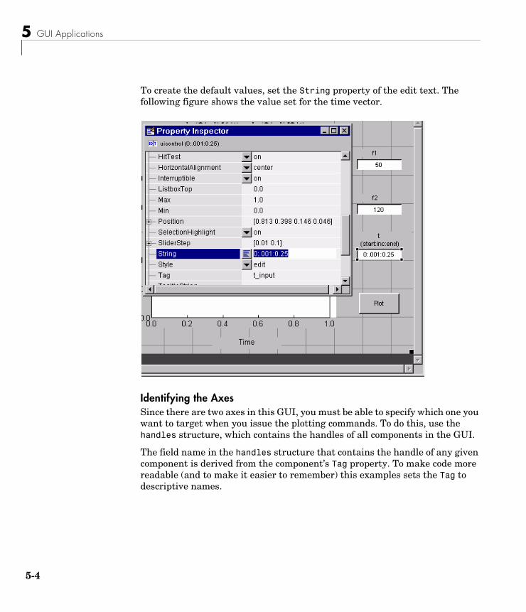
5 GUI Applications
5-4
To create the default values, set the String property of the edit text. The following figure shows the value set for the time vector.
Identifying the AxesSince there are two axes in this GUI, you must be able to specify which one you want to target when you issue the plotting commands. To do this, use the handles structure, which contains the handles of all components in the GUI.
The field name in the handles structure that contains the handle of any given component is derived from the component’s Tag property. To make code more readable (and to make it easier to remember) this examples sets the Tag to descriptive names.
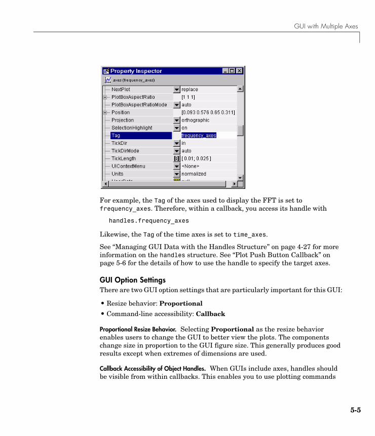
GUI with Multiple Axes
5-5
For example, the Tag of the axes used to display the FFT is set to frequency_axes. Therefore, within a callback, you access its handle with
handles.frequency_axes
Likewise, the Tag of the time axes is set to time_axes.
See “Managing GUI Data with the Handles Structure” on page 4-27 for more information on the handles structure. See “Plot Push Button Callback” on page 5-6 for the details of how to use the handle to specify the target axes.
GUI Option SettingsThere are two GUI option settings that are particularly important for this GUI:
• Resize behavior: Proportional
• Command-line accessibility: Callback
Proportional Resize Behavior. Selecting Proportional as the resize behavior enables users to change the GUI to better view the plots. The components change size in proportion to the GUI figure size. This generally produces good results except when extremes of dimensions are used.
Callback Accessibility of Object Handles. When GUIs include axes, handles should be visible from within callbacks. This enables you to use plotting commands
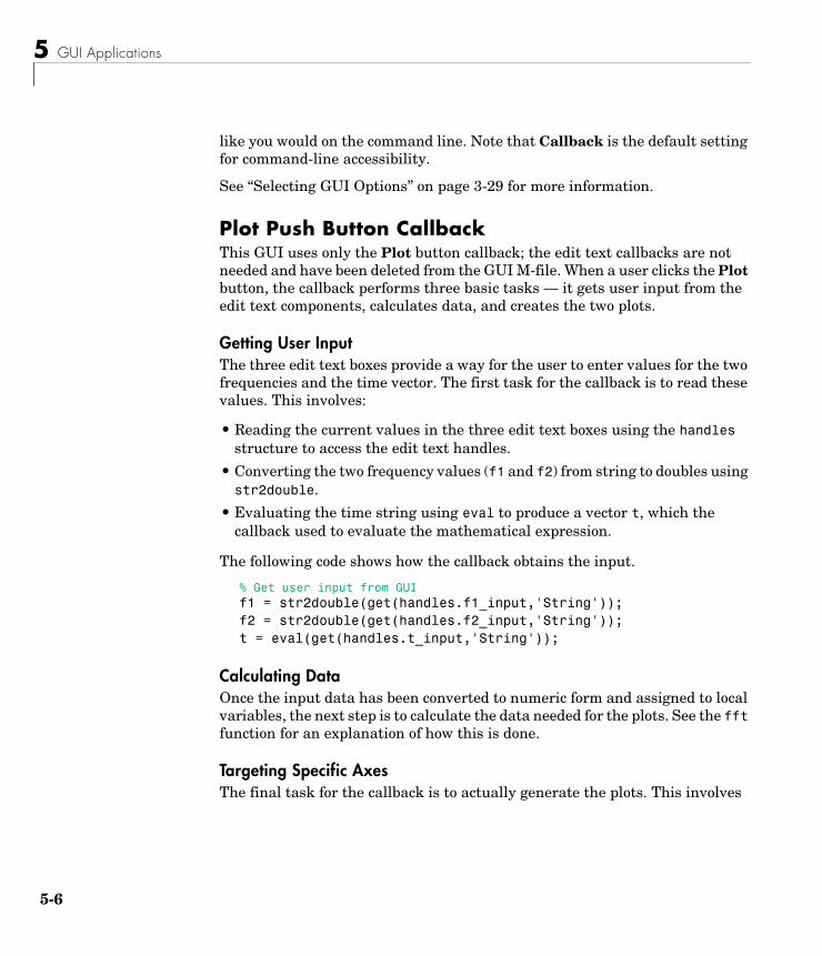
5 GUI Applications
5-6
like you would on the command line. Note that Callback is the default setting for command-line accessibility.
See “Selecting GUI Options” on page 3-29 for more information.
Plot Push Button CallbackThis GUI uses only the Plot button callback; the edit text callbacks are not needed and have been deleted from the GUI M-file. When a user clicks the Plot button, the callback performs three basic tasks — it gets user input from the edit text components, calculates data, and creates the two plots.
Getting User InputThe three edit text boxes provide a way for the user to enter values for the two frequencies and the time vector. The first task for the callback is to read these values. This involves:
• Reading the current values in the three edit text boxes using the handles structure to access the edit text handles.
• Converting the two frequency values (f1 and f2) from string to doubles using str2double.
• Evaluating the time string using eval to produce a vector t, which the callback used to evaluate the mathematical expression.
The following code shows how the callback obtains the input.
% Get user input from GUIf1 = str2double(get(handles.f1_input,'String'));f2 = str2double(get(handles.f2_input,'String'));t = eval(get(handles.t_input,'String'));
Calculating DataOnce the input data has been converted to numeric form and assigned to local variables, the next step is to calculate the data needed for the plots. See the fft function for an explanation of how this is done.
Targeting Specific AxesThe final task for the callback is to actually generate the plots. This involves
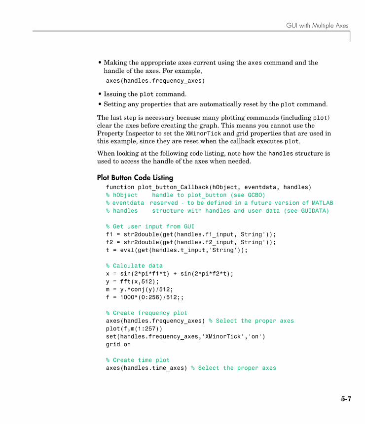
GUI with Multiple Axes
5-7
• Making the appropriate axes current using the axes command and the handle of the axes. For example,axes(handles.frequency_axes)
• Issuing the plot command.
• Setting any properties that are automatically reset by the plot command.
The last step is necessary because many plotting commands (including plot) clear the axes before creating the graph. This means you cannot use the Property Inspector to set the XMinorTick and grid properties that are used in this example, since they are reset when the callback executes plot.
When looking at the following code listing, note how the handles structure is used to access the handle of the axes when needed.
Plot Button Code Listingfunction plot_button_Callback(hObject, eventdata, handles)% hObject handle to plot_button (see GCBO)% eventdata reserved - to be defined in a future version of MATLAB% handles structure with handles and user data (see GUIDATA)
% Get user input from GUIf1 = str2double(get(handles.f1_input,'String'));f2 = str2double(get(handles.f2_input,'String'));t = eval(get(handles.t_input,'String'));
% Calculate datax = sin(2*pi*f1*t) + sin(2*pi*f2*t);y = fft(x,512);m = y.*conj(y)/512;f = 1000*(0:256)/512;;
% Create frequency plotaxes(handles.frequency_axes) % Select the proper axesplot(f,m(1:257))set(handles.frequency_axes,'XMinorTick','on')grid on
% Create time plotaxes(handles.time_axes) % Select the proper axes
5 GUI Applications
5-8
plot(t,x)set(handles.time_axes,'XMinorTick','on')grid on
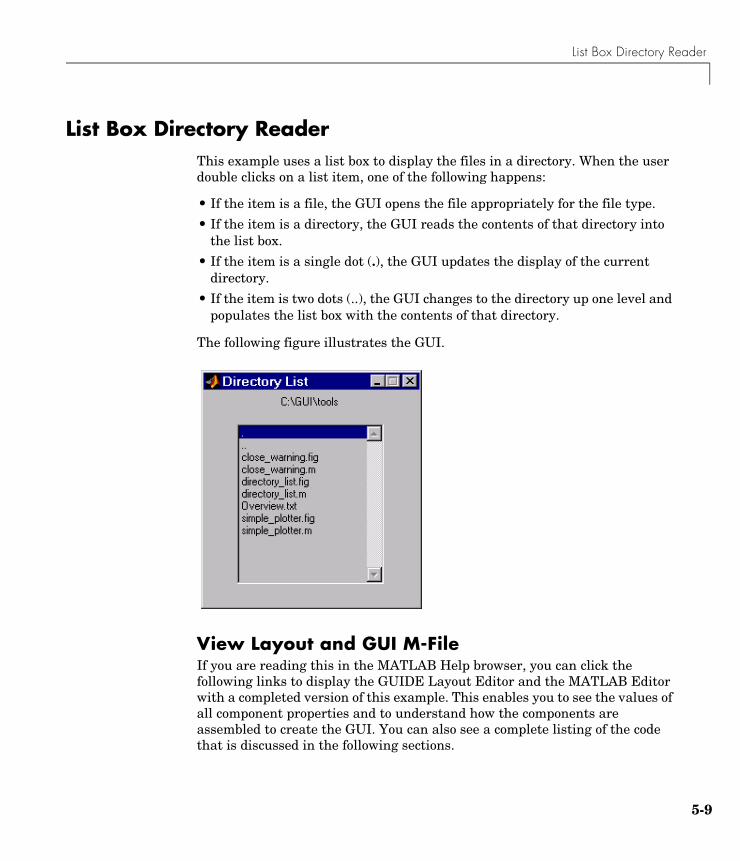
List Box Directory Reader
5-9
List Box Directory ReaderThis example uses a list box to display the files in a directory. When the user double clicks on a list item, one of the following happens:
• If the item is a file, the GUI opens the file appropriately for the file type.
• If the item is a directory, the GUI reads the contents of that directory into the list box.
• If the item is a single dot (.), the GUI updates the display of the current directory.
• If the item is two dots (..), the GUI changes to the directory up one level and populates the list box with the contents of that directory.
The following figure illustrates the GUI.
View Layout and GUI M-File If you are reading this in the MATLAB Help browser, you can click the following links to display the GUIDE Layout Editor and the MATLAB Editor with a completed version of this example. This enables you to see the values of all component properties and to understand how the components are assembled to create the GUI. You can also see a complete listing of the code that is discussed in the following sections.
5 GUI Applications
5-10
Note The following links execute MATLAB commands and are designed to work within the MATLAB Help browser. If you are reading this online or in PDF, you should go to the corresponding section in the MATLAB Help Browser to use the links.
• Click here to display this GUI in the Layout Editor.
• Click here to display the GUI M-file in the editor.
Implementing the GUIThe following sections describe the implementation:
• “Specifying the Directory to List” — shows how to pass a directory path as input argument when the GUI is run.
• “Loading the List Box” — describes the subfunction that loads the contents of the directory into the list box. This subfunction also saves information about the contents of a directory in the handles structure.
• “The List Box Callback” — explains how the list box is programmed to respond to user double clicks on items in the list box.
Specifying the Directory to ListYou can specify the directory to list when the GUI is first opened by passing the string 'create' and a string containing the full path to the directory as arguments. The syntax for doing this is list_box('create','dir_path'). If you do not specify a directory (i.e., if you call the GUI M-file with no input arguments), the GUI then uses the MATLAB current directory.
The default behavior of the GUI M-file that GUIDE generates is to run the GUI when there are no input arguments or to call a subfunction when the first input argument is a character string. This example changes this behavior so that you can call the M-file with
• No input arguments — run the GUI using the MATLAB current directory.
• First input argument is 'create' and second input argument is a string that specifies a valid path to a directory — run the GUI, displaying the specified directory.
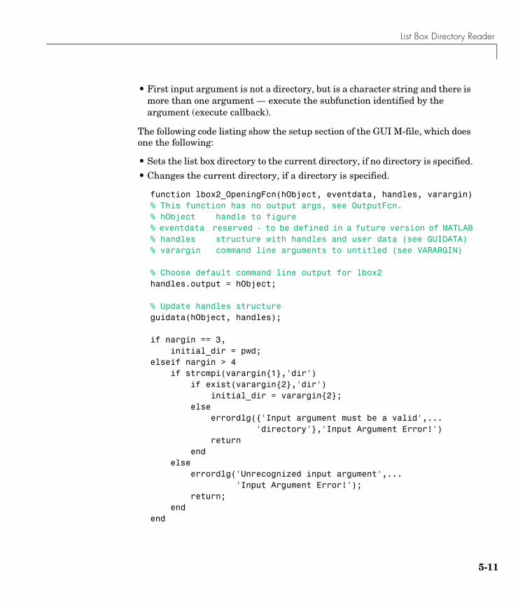
List Box Directory Reader
5-11
• First input argument is not a directory, but is a character string and there is more than one argument — execute the subfunction identified by the argument (execute callback).
The following code listing show the setup section of the GUI M-file, which does one the following:
• Sets the list box directory to the current directory, if no directory is specified.
• Changes the current directory, if a directory is specified.
function lbox2_OpeningFcn(hObject, eventdata, handles, varargin)% This function has no output args, see OutputFcn.% hObject handle to figure% eventdata reserved - to be defined in a future version of MATLAB% handles structure with handles and user data (see GUIDATA)% varargin command line arguments to untitled (see VARARGIN)
% Choose default command line output for lbox2handles.output = hObject;
% Update handles structureguidata(hObject, handles);
if nargin == 3, initial_dir = pwd;elseif nargin > 4 if strcmpi(varargin{1},'dir') if exist(varargin{2},'dir') initial_dir = varargin{2}; else errordlg({'Input argument must be a valid',... 'directory'},'Input Argument Error!') return end else errordlg('Unrecognized input argument',... 'Input Argument Error!'); return; endend
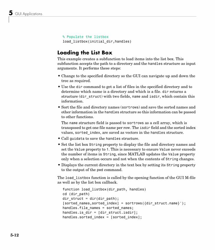
5 GUI Applications
5-12
% Populate the listboxload_listbox(initial_dir,handles)
Loading the List BoxThis example creates a subfunction to load items into the list box. This subfunction accepts the path to a directory and the handles structure as input arguments. It performs these steps:
• Change to the specified directory so the GUI can navigate up and down the tree as required.
• Use the dir command to get a list of files in the specified directory and to determine which name is a directory and which is a file. dir returns a structure (dir_struct) with two fields, name and isdir, which contain this information.
• Sort the file and directory names (sortrows) and save the sorted names and other information in the handles structure so this information can be passed to other functions.
The name structure field is passed to sortrows as a cell array, which is transposed to get one file name per row. The isdir field and the sorted index values, sorted_index, are saved as vectors in the handles structure.
• Call guidata to save the handles structure.
• Set the list box String property to display the file and directory names and set the Value property to 1. This is necessary to ensure Value never exceeds the number of items in String, since MATLAB updates the Value property only when a selection occurs and not when the contents of String changes.
• Displays the current directory in the text box by setting its String property to the output of the pwd command.
The load_listbox function is called by the opening function of the GUI M-file as well as by the list box callback.
function load_listbox(dir_path, handles)cd (dir_path)dir_struct = dir(dir_path);[sorted_names,sorted_index] = sortrows({dir_struct.name}');handles.file_names = sorted_names;handles.is_dir = [dir_struct.isdir];handles.sorted_index = [sorted_index];
List Box Directory Reader
5-13
guidata(handles.figure1,handles)set(handles.listbox1,'String',handles.file_names,...
'Value',1)set(handles.text1,'String',pwd)
The List Box CallbackThe list box callback handles only one case: a double-click on an item. Double clicking is the standard way to open a file from a list box. If the selected item is a file, it is passed to the open command; if it is a directory, the GUI changes to that directory and lists its contents.
Defining How to Open File TypesThe callback makes use of the fact that the open command can handle a number of different file types. However, the callback treats FIG-files differently. Instead of opening the FIG-file, it passes it to the guide command for editing.
Determining Which Item the User SelectedSince a single click on an item also invokes the list box callback, it is necessary to query the figure SelectionType property to determine when the user has performed a double click. A double-click on an item sets the SelectionType property to open.
All the items in the list box are referenced by an index from 1 to n, where 1 refers to the first item and n is the index of the nth item. MATLAB saves this index in the list box Value property.
The callback uses this index to get the name of the selected item from the list of items contained in the String property.
Determining if the Selected Item is a File or DirectoryThe load_listbox function uses the dir command to obtain a list of values that indicate whether an item is a file or directory. These values (1 for directory, 0 for file) are saved in the handles structure. The list box callback queries these values to determine if current selection is a file or directory and takes the following action:
• If the selection is a directory — change to the directory (cd) and call load_listbox again to populate the list box with the contents of the new directory.
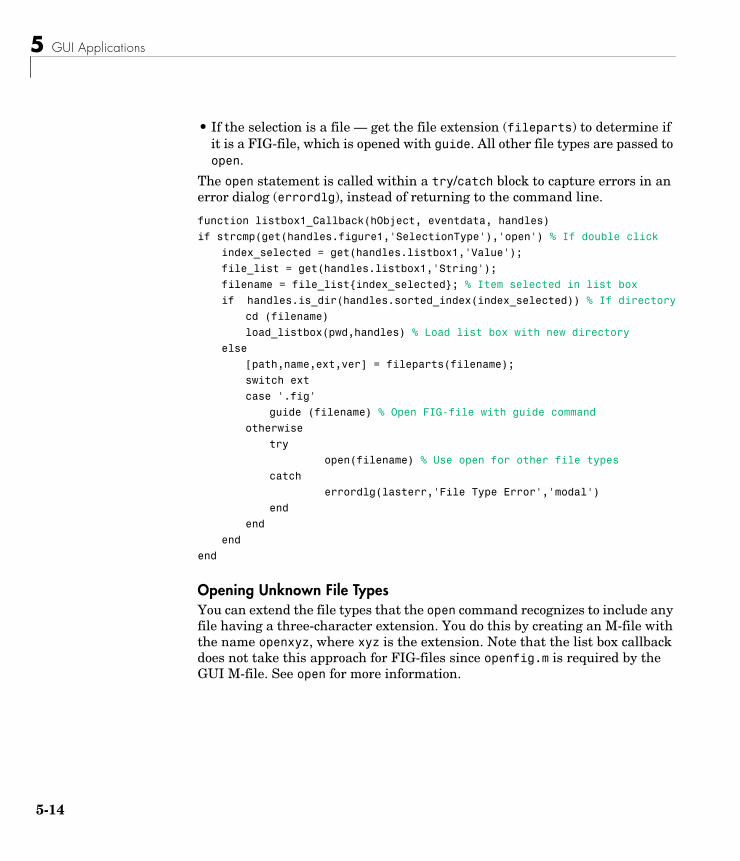
5 GUI Applications
5-14
• If the selection is a file — get the file extension (fileparts) to determine if it is a FIG-file, which is opened with guide. All other file types are passed to open.
The open statement is called within a try/catch block to capture errors in an error dialog (errordlg), instead of returning to the command line.
function listbox1_Callback(hObject, eventdata, handles)
if strcmp(get(handles.figure1,'SelectionType'),'open') % If double click
index_selected = get(handles.listbox1,'Value');
file_list = get(handles.listbox1,'String');
filename = file_list{index_selected}; % Item selected in list box
if handles.is_dir(handles.sorted_index(index_selected)) % If directory
cd (filename)
load_listbox(pwd,handles) % Load list box with new directory
else
[path,name,ext,ver] = fileparts(filename);
switch ext
case '.fig'
guide (filename) % Open FIG-file with guide command
otherwise
try
open(filename) % Use open for other file types
catch
errordlg(lasterr,'File Type Error','modal')
end
end
end
end
Opening Unknown File TypesYou can extend the file types that the open command recognizes to include any file having a three-character extension. You do this by creating an M-file with the name openxyz, where xyz is the extension. Note that the list box callback does not take this approach for FIG-files since openfig.m is required by the GUI M-file. See open for more information.
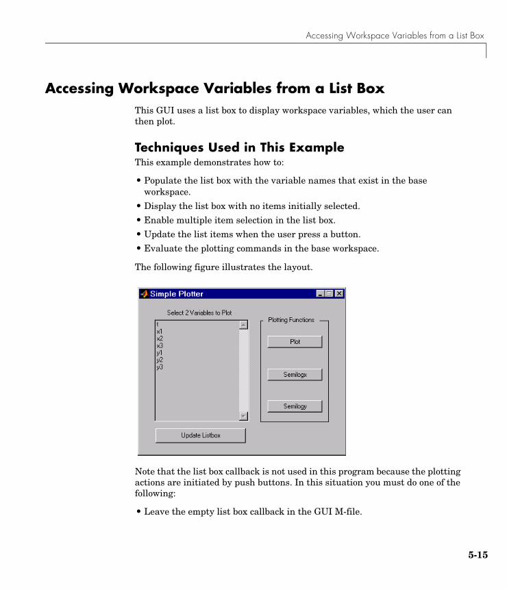
Accessing Workspace Variables from a List Box
5-15
Accessing Workspace Variables from a List BoxThis GUI uses a list box to display workspace variables, which the user can then plot.
Techniques Used in This ExampleThis example demonstrates how to:
• Populate the list box with the variable names that exist in the base workspace.
• Display the list box with no items initially selected.
• Enable multiple item selection in the list box.
• Update the list items when the user press a button.
• Evaluate the plotting commands in the base workspace.
The following figure illustrates the layout.
Note that the list box callback is not used in this program because the plotting actions are initiated by push buttons. In this situation you must do one of the following:
• Leave the empty list box callback in the GUI M-file.
5 GUI Applications
5-16
• Delete the string assigned to the list box Callback property.
View Completed Layout and Its GUI M-FileIf you are reading this in the MATLAB Help browser, you can click the following links to display the GUIDE Layout Editor and the MATLAB Editor with a completed version of this example. This enables you to see the values of all component properties and to understand how the components are assembled to create the GUI. You can also see a complete listing of the code that is discussed in the following sections.
Note The following links execute MATLAB commands and are designed to work within the MATLAB Help browser. If you are reading this online or in PDF, you should go to the corresponding section in the MATLAB Help Browser to use the links.
• Click here to display this GUI in the Layout Editor.
• Click here to display the GUI M-file in the editor.
Reading Workspace VariablesWhen the GUI initializes, it needs to query the workspace variables and set the list box String property to display these variable names. Adding the following subfunction to the GUI M-file accomplishes this using evalin to execute the who command in the base workspace. The who command returns a cell array of strings, which are used to populate the list box.
function update_listbox(handles)vars = evalin('base','who');set(handles.listbox1,'String',vars)
The function’s input argument is the handles structure generated by the GUI M-file. This structure contains the handle of the list box, as well as the handles all other components in the GUI.
The callback for the Update Listbox push button also calls update_listbox.
Accessing Workspace Variables from a List Box
5-17
Reading the Selections from the List BoxThis GUI requires the user to select two variables from the workspace and then choose one of three plot commands to create the graph: plot, semilogx, or semilogy.
Enabling Multiple SelectionTo enable multiple selection in a list box, you must set the Min and Max properties so that Max Min > 1. This requires you to change the default Min and Max values of 0 and 1 to meet these conditions. Use the Property Inspector to set these properties on the list box.
How Users Select Multiple ItemsList box multiple selection follows the standard for most systems:
• Control-click left mouse button — noncontiguous multi-item selection
• Shift-click left mouse button — contiguous multi-item selection
Users must use one of these techniques to select the two variables required to create the plot.
Returning Variable Names for the Plotting FunctionsThe get_var_names subroutine returns the two variable names that are selected when the user clicks on one of the three plotting buttons. The function
• Gets the list of all items in the list box from the String property.
• Gets the indices of the selected items from the Value property.
• Returns two string variables, if there are two items selected. Otherwise get_var_names displays an error dialog explaining that the user must select two variables.
Here is the code for get_var_names:
function [var1,var2] = get_var_names(handles)list_entries = get(handles.listbox1,'String');index_selected = get(handles.listbox1,'Value');if length(index_selected) ~= 2
errordlg('You must select two variables',...'Incorrect Selection','modal')
else
5 GUI Applications
5-18
var1 = list_entries{index_selected(1)};var2 = list_entries{index_selected(2)};
end
Callbacks for the Plotting ButtonsThe callbacks for the plotting buttons call get_var_names to get the names of the variables to plot and then call evalin to execute the plot commands in the base workspace.
For example, here is the callback for the plot function:
function plot_button_Callback(hObject, eventdata, handles)[x,y] = get_var_names(handles);evalin('base',['plot(' x ',' y ')'])
The command to evaluate is created by concatenating the strings and variables that result in the command:
plot(x,y)
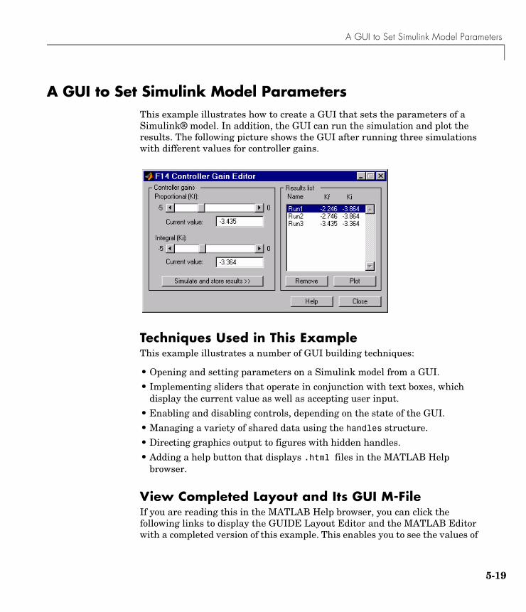
A GUI to Set Simulink Model Parameters
5-19
A GUI to Set Simulink Model Parameters This example illustrates how to create a GUI that sets the parameters of a Simulink® model. In addition, the GUI can run the simulation and plot the results. The following picture shows the GUI after running three simulations with different values for controller gains.
Techniques Used in This ExampleThis example illustrates a number of GUI building techniques:
• Opening and setting parameters on a Simulink model from a GUI.
• Implementing sliders that operate in conjunction with text boxes, which display the current value as well as accepting user input.
• Enabling and disabling controls, depending on the state of the GUI.
• Managing a variety of shared data using the handles structure.
• Directing graphics output to figures with hidden handles.
• Adding a help button that displays .html files in the MATLAB Help browser.
View Completed Layout and Its GUI M-FileIf you are reading this in the MATLAB Help browser, you can click the following links to display the GUIDE Layout Editor and the MATLAB Editor with a completed version of this example. This enables you to see the values of
5 GUI Applications
5-20
all component properties and to understand how the components are assembled to create the GUI. You can also see a complete listing of the code that is discussed in the following sections.
Note The following links execute MATLAB commands and are designed to work within the MATLAB Help browser. If you are reading this online or in PDF, you should go to the corresponding section in the MATLAB Help Browser to use the links.
• Click here to display this GUI in the Layout Editor.
• Click here to display the GUI M-file in the editor.
How to Use the GUI (Text of GUI Help)You can use the F14 Controller Gain Editor to analyze how changing the gains used in the Proportional-Integral Controller affect the aircraft's angle of attack and the amount of G force the pilot feels.
Note that the Simulink diagram f14.mdl must be open to run this GUI. If you close the F14 Simulink model, the GUI reopens it whenever it requires the model to execute.
Changing the Controller GainsYou can change gains in two blocks:
• The Proportional gain (Kf) in the Gain block
• The Integral gain (Ki) in the Transfer Function block
You can change either of the gains in one of the two ways:
• Move the slider associated with that gain.
• Type a new value into the Current value edit field associated with that gain.
The block’s values are updated as soon as you enter the new value in the GUI.
A GUI to Set Simulink Model Parameters
5-21
Running the SimulationOnce you have set the gain values, you can run the simulation by clicking the Simulate and store results button. The simulation time and output vectors are stored in the Results list.
Plotting the ResultsYou can generate a plot of one or more simulation results by selecting the row of results (Run1, Run2, etc.) in the Results list that you want to plot and clicking the Plot button. If you select multiple rows, the graph contains a plot of each result.
The graph is displayed in a figure, which is cleared each time you click the Plot button. The figure’s handle is hidden so that only the GUI can display graphs in this window.
Removing ResultsTo remove a result from the Results list, select the row or rows you want to remove and click the Remove button.
Running the GUIThe GUI is nonblocking and nonmodal since it is designed to be used as an analysis tool.
GUI Options SettingsThis GUI uses the following GUI option settings:
• Resize behavior: Non-resizable
• Command-line accessibility: Off
• M-file options selected:
- Generate callback function prototypes
- GUI allows only one instance to run
Opening the Simulink Block DiagramsThis example is designed to work with the F14 Simulink model. Since the GUI sets parameters and runs the simulation, the F14 model must be open when the GUI is displayed. When the GUI M-file runs the GUI, it executes the model_open subfunction. The purpose of the subfunction is to
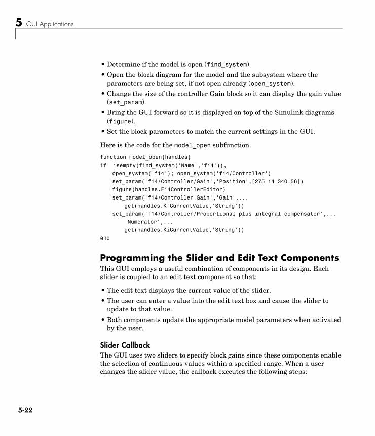
5 GUI Applications
5-22
• Determine if the model is open (find_system).
• Open the block diagram for the model and the subsystem where the parameters are being set, if not open already (open_system).
• Change the size of the controller Gain block so it can display the gain value (set_param).
• Bring the GUI forward so it is displayed on top of the Simulink diagrams (figure).
• Set the block parameters to match the current settings in the GUI.
Here is the code for the model_open subfunction.
function model_open(handles)
if isempty(find_system('Name','f14')),
open_system('f14'); open_system('f14/Controller')
set_param('f14/Controller/Gain','Position',[275 14 340 56])
figure(handles.F14ControllerEditor)
set_param('f14/Controller Gain','Gain',...
get(handles.KfCurrentValue,'String'))
set_param('f14/Controller/Proportional plus integral compensator',...
'Numerator',...
get(handles.KiCurrentValue,'String'))
end
Programming the Slider and Edit Text ComponentsThis GUI employs a useful combination of components in its design. Each slider is coupled to an edit text component so that:
• The edit text displays the current value of the slider.
• The user can enter a value into the edit text box and cause the slider to update to that value.
• Both components update the appropriate model parameters when activated by the user.
Slider CallbackThe GUI uses two sliders to specify block gains since these components enable the selection of continuous values within a specified range. When a user changes the slider value, the callback executes the following steps:
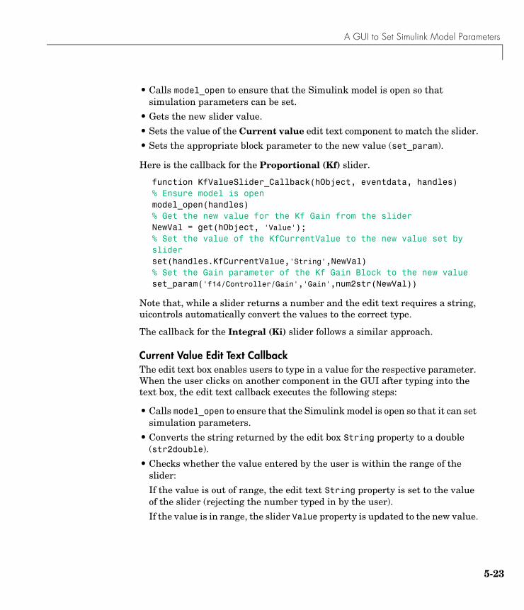
A GUI to Set Simulink Model Parameters
5-23
• Calls model_open to ensure that the Simulink model is open so that simulation parameters can be set.
• Gets the new slider value.
• Sets the value of the Current value edit text component to match the slider.
• Sets the appropriate block parameter to the new value (set_param).
Here is the callback for the Proportional (Kf) slider.
function KfValueSlider_Callback(hObject, eventdata, handles)% Ensure model is openmodel_open(handles)% Get the new value for the Kf Gain from the sliderNewVal = get(hObject, 'Value');% Set the value of the KfCurrentValue to the new value set by sliderset(handles.KfCurrentValue,'String',NewVal)% Set the Gain parameter of the Kf Gain Block to the new valueset_param('f14/Controller/Gain','Gain',num2str(NewVal))
Note that, while a slider returns a number and the edit text requires a string, uicontrols automatically convert the values to the correct type.
The callback for the Integral (Ki) slider follows a similar approach.
Current Value Edit Text CallbackThe edit text box enables users to type in a value for the respective parameter. When the user clicks on another component in the GUI after typing into the text box, the edit text callback executes the following steps:
• Calls model_open to ensure that the Simulink model is open so that it can set simulation parameters.
• Converts the string returned by the edit box String property to a double (str2double).
• Checks whether the value entered by the user is within the range of the slider:
If the value is out of range, the edit text String property is set to the value of the slider (rejecting the number typed in by the user).
If the value is in range, the slider Value property is updated to the new value.
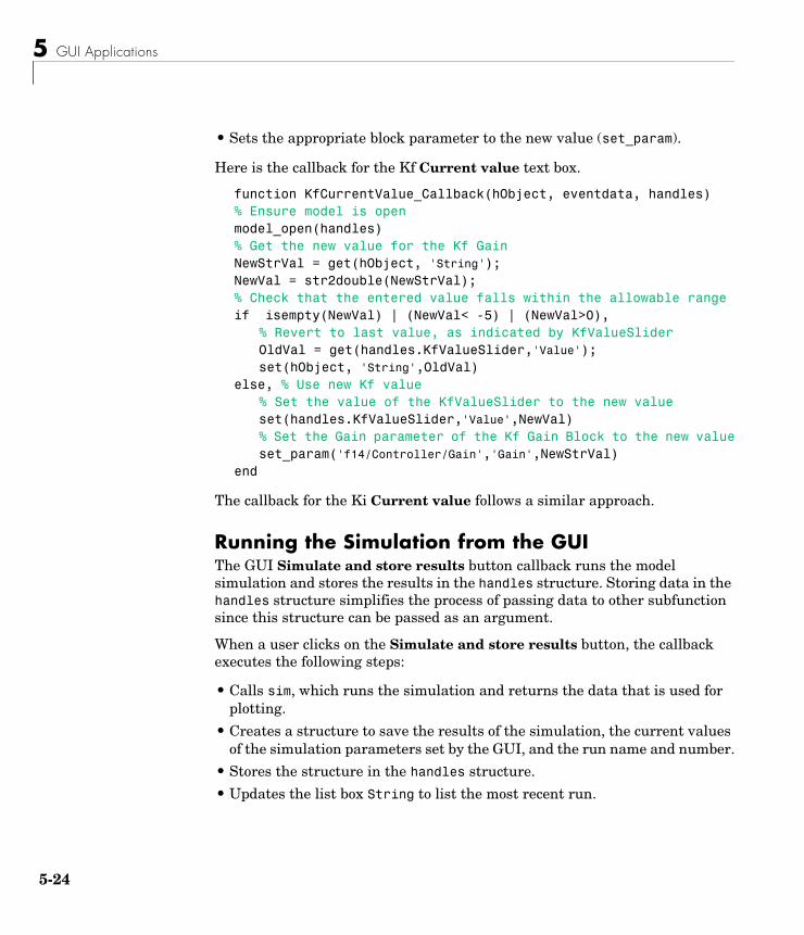
5 GUI Applications
5-24
• Sets the appropriate block parameter to the new value (set_param).
Here is the callback for the Kf Current value text box.
function KfCurrentValue_Callback(hObject, eventdata, handles)% Ensure model is openmodel_open(handles)% Get the new value for the Kf GainNewStrVal = get(hObject, 'String');NewVal = str2double(NewStrVal);% Check that the entered value falls within the allowable rangeif isempty(NewVal) | (NewVal< -5) | (NewVal>0),
% Revert to last value, as indicated by KfValueSliderOldVal = get(handles.KfValueSlider,'Value');set(hObject, 'String',OldVal)
else, % Use new Kf value% Set the value of the KfValueSlider to the new valueset(handles.KfValueSlider,'Value',NewVal)% Set the Gain parameter of the Kf Gain Block to the new valueset_param('f14/Controller/Gain','Gain',NewStrVal)
end
The callback for the Ki Current value follows a similar approach.
Running the Simulation from the GUIThe GUI Simulate and store results button callback runs the model simulation and stores the results in the handles structure. Storing data in the handles structure simplifies the process of passing data to other subfunction since this structure can be passed as an argument.
When a user clicks on the Simulate and store results button, the callback executes the following steps:
• Calls sim, which runs the simulation and returns the data that is used for plotting.
• Creates a structure to save the results of the simulation, the current values of the simulation parameters set by the GUI, and the run name and number.
• Stores the structure in the handles structure.
• Updates the list box String to list the most recent run.
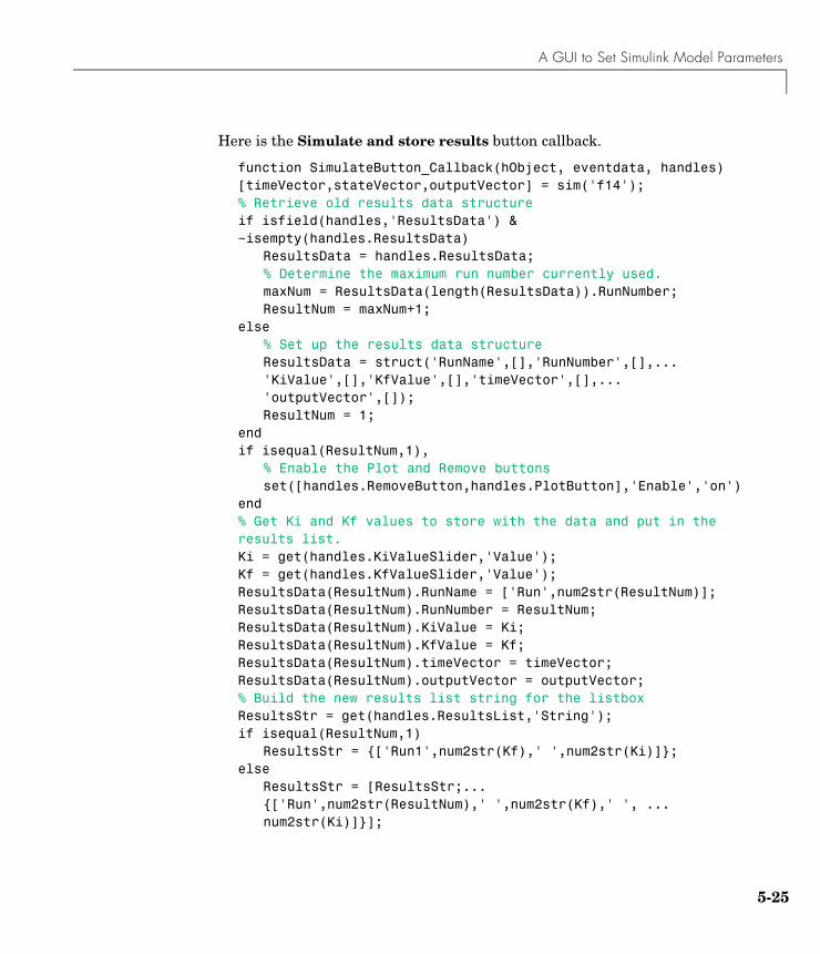
A GUI to Set Simulink Model Parameters
5-25
Here is the Simulate and store results button callback.
function SimulateButton_Callback(hObject, eventdata, handles)[timeVector,stateVector,outputVector] = sim('f14');% Retrieve old results data structureif isfield(handles,'ResultsData') & ~isempty(handles.ResultsData)
ResultsData = handles.ResultsData;% Determine the maximum run number currently used.maxNum = ResultsData(length(ResultsData)).RunNumber;ResultNum = maxNum+1;
else % Set up the results data structureResultsData = struct('RunName',[],'RunNumber',[],...'KiValue',[],'KfValue',[],'timeVector',[],...'outputVector',[]);ResultNum = 1;
endif isequal(ResultNum,1),
% Enable the Plot and Remove buttonsset([handles.RemoveButton,handles.PlotButton],'Enable','on')
end% Get Ki and Kf values to store with the data and put in the results list.Ki = get(handles.KiValueSlider,'Value');Kf = get(handles.KfValueSlider,'Value');ResultsData(ResultNum).RunName = ['Run',num2str(ResultNum)];ResultsData(ResultNum).RunNumber = ResultNum;ResultsData(ResultNum).KiValue = Ki;ResultsData(ResultNum).KfValue = Kf;ResultsData(ResultNum).timeVector = timeVector;ResultsData(ResultNum).outputVector = outputVector;% Build the new results list string for the listboxResultsStr = get(handles.ResultsList,'String');if isequal(ResultNum,1)
ResultsStr = {['Run1',num2str(Kf),' ',num2str(Ki)]};else
ResultsStr = [ResultsStr;...{['Run',num2str(ResultNum),' ',num2str(Kf),' ', ...num2str(Ki)]}];
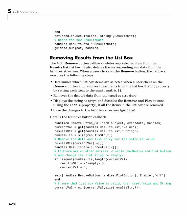
5 GUI Applications
5-26
endset(handles.ResultsList,'String',ResultsStr);% Store the new ResultsDatahandles.ResultsData = ResultsData;guidata(hObject, handles)
Removing Results from the List BoxThe GUI Remove button callback deletes any selected item from the Results list list box. It also deletes the corresponding run data from the handles structure. When a user clicks on the Remove button, the callback executes the following steps:
• Determines which list box items are selected when a user clicks on the Remove button and removes these items from the list box String property by setting each item to the empty matrix [].
• Removes the deleted data from the handles structure.
• Displays the string <empty> and disables the Remove and Plot buttons (using the Enable property), if all the items in the list box are removed.
• Save the changes to the handles structure (guidata).
Here is the Remove button callback.
function RemoveButton_Callback(hObject, eventdata, handles)currentVal = get(handles.ResultsList,'Value');resultsStr = get(handles.ResultsList,'String');numResults = size(resultsStr,1);% Remove the data and list entry for the selected valueresultsStr(currentVal) =[];handles.ResultsData(currentVal)=[];% If there are no other entries, disable the Remove and Plot button% and change the list sting to <empty>if isequal(numResults,length(currentVal)),
resultsStr = {'<empty>'};currentVal = 1;
set([handles.RemoveButton,handles.PlotButton],'Enable','off')end% Ensure that list box Value is valid, then reset Value and StringcurrentVal = min(currentVal,size(resultsStr,1));
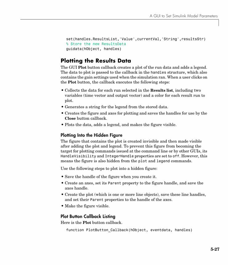
A GUI to Set Simulink Model Parameters
5-27
set(handles.ResultsList,'Value',currentVal,'String',resultsStr)% Store the new ResultsDataguidata(hObject, handles)
Plotting the Results DataThe GUI Plot button callback creates a plot of the run data and adds a legend. The data to plot is passed to the callback in the handles structure, which also contains the gain settings used when the simulation ran. When a user clicks on the Plot button, the callback executes the following steps:
• Collects the data for each run selected in the Results list, including two variables (time vector and output vector) and a color for each result run to plot.
• Generates a string for the legend from the stored data.
• Creates the figure and axes for plotting and saves the handles for use by the Close button callback.
• Plots the data, adds a legend, and makes the figure visible.
Plotting Into the Hidden FigureThe figure that contains the plot is created invisible and then made visible after adding the plot and legend. To prevent this figure from becoming the target for plotting commands issued at the command line or by other GUIs, its HandleVisibility and IntegerHandle properties are set to off. However, this means the figure is also hidden from the plot and legend commands.
Use the following steps to plot into a hidden figure:
• Save the handle of the figure when you create it.
• Create an axes, set its Parent property to the figure handle, and save the axes handle.
• Create the plot (which is one or more line objects), save these line handles, and set their Parent properties to the handle of the axes.
• Make the figure visible.
Plot Button Callback ListingHere is the Plot button callback.
function PlotButton_Callback(hObject, eventdata, handles)
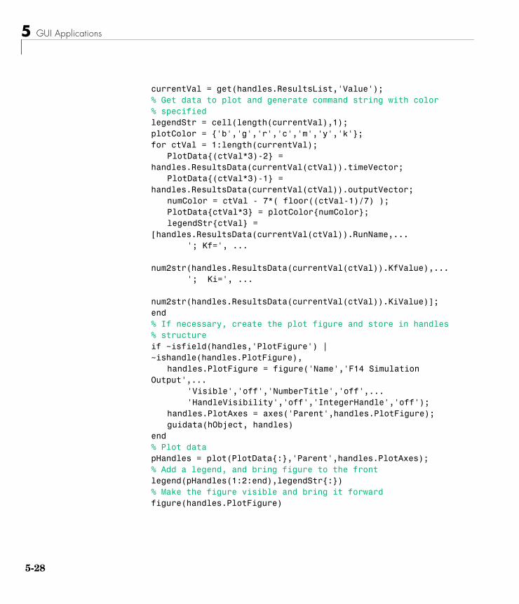
5 GUI Applications
5-28
currentVal = get(handles.ResultsList,'Value');% Get data to plot and generate command string with color% specifiedlegendStr = cell(length(currentVal),1);plotColor = {'b','g','r','c','m','y','k'};for ctVal = 1:length(currentVal);
PlotData{(ctVal*3)-2} = handles.ResultsData(currentVal(ctVal)).timeVector;
PlotData{(ctVal*3)-1} = handles.ResultsData(currentVal(ctVal)).outputVector;
numColor = ctVal - 7*( floor((ctVal-1)/7) );PlotData{ctVal*3} = plotColor{numColor};legendStr{ctVal} =
[handles.ResultsData(currentVal(ctVal)).RunName,...'; Kf=', ...
num2str(handles.ResultsData(currentVal(ctVal)).KfValue),...'; Ki=', ...
num2str(handles.ResultsData(currentVal(ctVal)).KiValue)];end% If necessary, create the plot figure and store in handles% structureif ~isfield(handles,'PlotFigure') | ~ishandle(handles.PlotFigure),
handles.PlotFigure = figure('Name','F14 Simulation Output',...
'Visible','off','NumberTitle','off',...'HandleVisibility','off','IntegerHandle','off');
handles.PlotAxes = axes('Parent',handles.PlotFigure);guidata(hObject, handles)
end% Plot datapHandles = plot(PlotData{:},'Parent',handles.PlotAxes);% Add a legend, and bring figure to the frontlegend(pHandles(1:2:end),legendStr{:})% Make the figure visible and bring it forwardfigure(handles.PlotFigure)
A GUI to Set Simulink Model Parameters
5-29
The GUI Help ButtonThe GUI Help button callback displays an HTML file in the MATLAB Help browser. It uses two commands:
• The which command returns the full path to the file when it is on the MATLAB path
• The web command displays the file in the Help browser.
This is the Help button callback.
function HelpButton_Callback(hObject, eventdata, handles)HelpPath = which('f14ex_help.html');web(HelpPath);
You can also display the help document in a Web browser or load an external URL. See the Web documentation for a description of these options.
Closing the GUIThe GUI Close button callback closes the plot figure, if one exists and then closes the GUI. The handle of the plot figure and the GUI figure are available from the handles structure. The callback executes two steps:
• Checks to see if there is a PlotFigure field in the handles structure and if it contains a valid figure handle (the user could have closed the figure manually).
• Closes the GUI figure
This is the Close button callback.
function CloseButton_Callback(hObject, eventdata, handles)% Close the GUI and any plot window that is openif isfield(handles,'PlotFigure') & ishandle(handles.PlotFigure),
close(handles.PlotFigure);endclose(handles.F14ControllerEditor);
The List Box Callback and Create FunctionThis GUI does not use the list box callback since the actions performed on list box items are carried out by push buttons (Simulate and store results, Remove, and Plot). However, GUIDE automatically inserts a callback stub
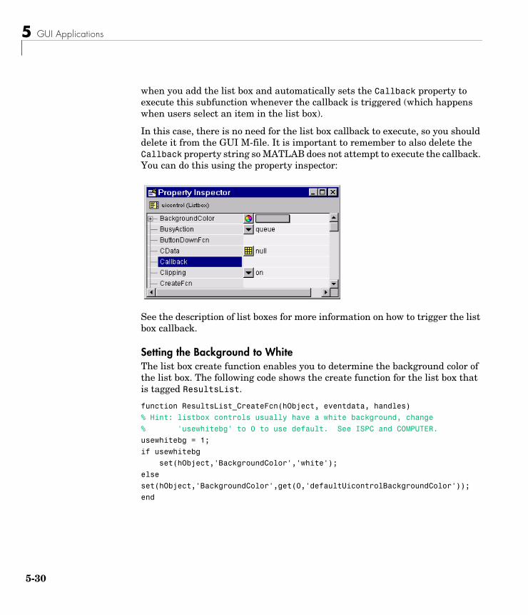
5 GUI Applications
5-30
when you add the list box and automatically sets the Callback property to execute this subfunction whenever the callback is triggered (which happens when users select an item in the list box).
In this case, there is no need for the list box callback to execute, so you should delete it from the GUI M-file. It is important to remember to also delete the Callback property string so MATLAB does not attempt to execute the callback. You can do this using the property inspector:
See the description of list boxes for more information on how to trigger the list box callback.
Setting the Background to WhiteThe list box create function enables you to determine the background color of the list box. The following code shows the create function for the list box that is tagged ResultsList.
function ResultsList_CreateFcn(hObject, eventdata, handles)
% Hint: listbox controls usually have a white background, change
% 'usewhitebg' to 0 to use default. See ISPC and COMPUTER.
usewhitebg = 1;
if usewhitebg
set(hObject,'BackgroundColor','white');
else
set(hObject,'BackgroundColor',get(0,'defaultUicontrolBackgroundColor'));
end
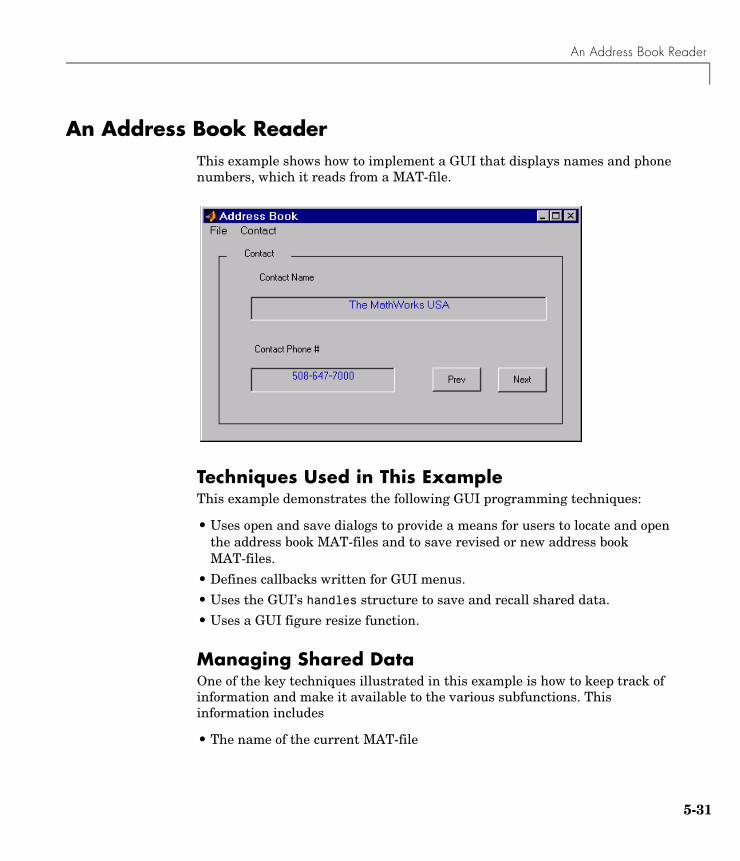
An Address Book Reader
5-31
An Address Book ReaderThis example shows how to implement a GUI that displays names and phone numbers, which it reads from a MAT-file.
Techniques Used in This ExampleThis example demonstrates the following GUI programming techniques:
• Uses open and save dialogs to provide a means for users to locate and open the address book MAT-files and to save revised or new address book MAT-files.
• Defines callbacks written for GUI menus.
• Uses the GUI’s handles structure to save and recall shared data.
• Uses a GUI figure resize function.
Managing Shared DataOne of the key techniques illustrated in this example is how to keep track of information and make it available to the various subfunctions. This information includes
• The name of the current MAT-file
5 GUI Applications
5-32
• The names and phone numbers stored in the MAT-file
• An index pointer that indicates the current name and phone number, which must be updated as the user pages through the address book
• The figure position and size
• The handles of all GUI components
The descriptions of the subfunctions that follow illustrate how to save and retrieve information from the handles structure. See “Sharing Data with the Handles Structure” on page 4-2 for background information on this structure.
View Completed Layout and Its GUI M-FileIf you are reading this in the MATLAB Help browser, you can click the following links to display the GUIDE Layout Editor and the MATLAB Editor with a completed version of this example. This enables you to see the values of all component properties and to understand how the components are assembled to create the GUI. You can also see a complete listing of the code that is discussed in the following sections.
Note The following links execute MATLAB commands and are designed to work within the MATLAB Help browser. If you are reading this online or in PDF, you should go to the corresponding section in the MATLAB Help Browser to use the links.
• Click here to display this GUI in the Layout Editor.
• Click here to display the GUI M-file in the MATLAB Editor.
Running the GUIThe GUI is nonblocking and nonmodal since it is designed to be displayed while you perform other MATLAB tasks.
GUI Option SettingsThis GUI uses the following GUI option settings:
• Resize behavior: User-specified
• Command-line accessibility: Off
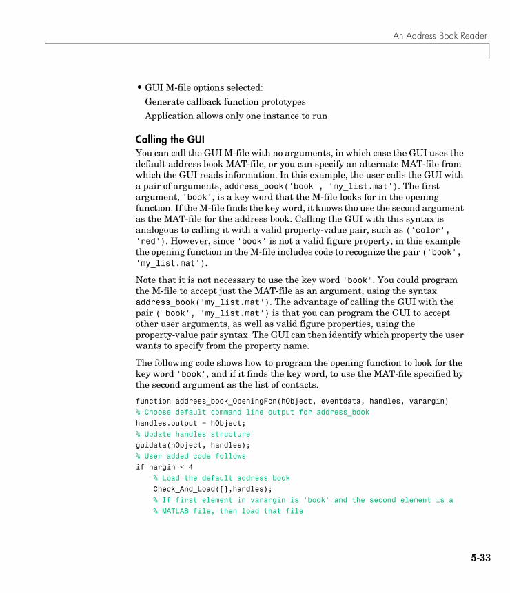
An Address Book Reader
5-33
• GUI M-file options selected:
Generate callback function prototypes
Application allows only one instance to run
Calling the GUIYou can call the GUI M-file with no arguments, in which case the GUI uses the default address book MAT-file, or you can specify an alternate MAT-file from which the GUI reads information. In this example, the user calls the GUI with a pair of arguments, address_book('book', 'my_list.mat'). The first argument, 'book', is a key word that the M-file looks for in the opening function. If the M-file finds the key word, it knows tho use the second argument as the MAT-file for the address book. Calling the GUI with this syntax is analogous to calling it with a valid property-value pair, such as ('color', 'red'). However, since 'book' is not a valid figure property, in this example the opening function in the M-file includes code to recognize the pair ('book', 'my_list.mat').
Note that it is not necessary to use the key word 'book'. You could program the M-file to accept just the MAT-file as an argument, using the syntax address_book('my_list.mat'). The advantage of calling the GUI with the pair ('book', 'my_list.mat') is that you can program the GUI to accept other user arguments, as well as valid figure properties, using the property-value pair syntax. The GUI can then identify which property the user wants to specify from the property name.
The following code shows how to program the opening function to look for the key word 'book', and if it finds the key word, to use the MAT-file specified by the second argument as the list of contacts.
function address_book_OpeningFcn(hObject, eventdata, handles, varargin)
% Choose default command line output for address_book
handles.output = hObject;
% Update handles structure
guidata(hObject, handles);
% User added code follows
if nargin < 4
% Load the default address book
Check_And_Load([],handles);
% If first element in varargin is 'book' and the second element is a
% MATLAB file, then load that file
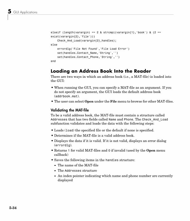
5 GUI Applications
5-34
elseif (length(varargin) == 2 & strcmpi(varargin{1},'book') & (2 ==
exist(varargin{2},'file')))
Check_And_Load(varargin{2},handles);
else
errordlg('File Not Found','File Load Error')
set(handles.Contact_Name,'String','')
set(handles.Contact_Phone,'String','')
end
Loading an Address Book Into the ReaderThere are two ways in which an address book (i.e., a MAT-file) is loaded into the GUI:
• When running the GUI, you can specify a MAT-file as an argument. If you do not specify an argument, the GUI loads the default address book (addrbook.mat).
• The user can select Open under the File menu to browse for other MAT-files.
Validating the MAT-fileTo be a valid address book, the MAT-file must contain a structure called Addresses that has two fields called Name and Phone. The Check_And_Load subfunction validates and loads the data with the following steps:
• Loads (load) the specified file or the default if none is specified.
• Determines if the MAT-file is a valid address book.
• Displays the data if it is valid. If it is not valid, displays an error dialog (errordlg).
• Returns 1 for valid MAT-files and 0 if invalid (used by the Open menu callback)
• Saves the following items in the handles structure:
- The name of the MAT-file
- The Addresses structure
- An index pointer indicating which name and phone number are currently displayed
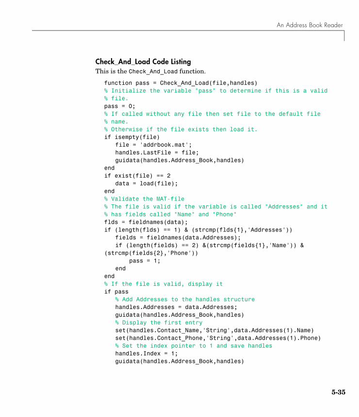
An Address Book Reader
5-35
Check_And_Load Code ListingThis is the Check_And_Load function.
function pass = Check_And_Load(file,handles)% Initialize the variable "pass" to determine if this is a valid% file.pass = 0;% If called without any file then set file to the default file% name.% Otherwise if the file exists then load it.if isempty(file)
file = 'addrbook.mat';handles.LastFile = file;guidata(handles.Address_Book,handles)
endif exist(file) == 2
data = load(file);end% Validate the MAT-file% The file is valid if the variable is called "Addresses" and it% has fields called "Name" and "Phone"flds = fieldnames(data);if (length(flds) == 1) & (strcmp(flds{1},'Addresses'))
fields = fieldnames(data.Addresses);if (length(fields) == 2) &(strcmp(fields{1},'Name')) &
(strcmp(fields{2},'Phone'))pass = 1;
endend% If the file is valid, display itif pass
% Add Addresses to the handles structurehandles.Addresses = data.Addresses;guidata(handles.Address_Book,handles)% Display the first entryset(handles.Contact_Name,'String',data.Addresses(1).Name)set(handles.Contact_Phone,'String',data.Addresses(1).Phone)% Set the index pointer to 1 and save handleshandles.Index = 1;guidata(handles.Address_Book,handles)
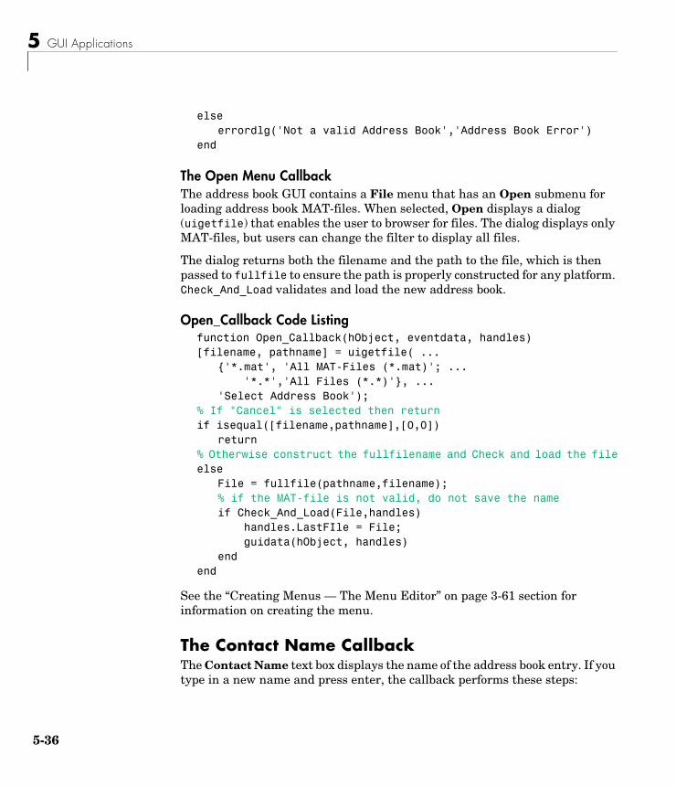
5 GUI Applications
5-36
elseerrordlg('Not a valid Address Book','Address Book Error')
end
The Open Menu CallbackThe address book GUI contains a File menu that has an Open submenu for loading address book MAT-files. When selected, Open displays a dialog (uigetfile) that enables the user to browser for files. The dialog displays only MAT-files, but users can change the filter to display all files.
The dialog returns both the filename and the path to the file, which is then passed to fullfile to ensure the path is properly constructed for any platform. Check_And_Load validates and load the new address book.
Open_Callback Code Listingfunction Open_Callback(hObject, eventdata, handles)[filename, pathname] = uigetfile( ...
{'*.mat', 'All MAT-Files (*.mat)'; ...'*.*','All Files (*.*)'}, ...
'Select Address Book');% If "Cancel" is selected then returnif isequal([filename,pathname],[0,0])
return% Otherwise construct the fullfilename and Check and load the fileelse
File = fullfile(pathname,filename);% if the MAT-file is not valid, do not save the nameif Check_And_Load(File,handles)
handles.LastFIle = File;guidata(hObject, handles)
endend
See the “Creating Menus — The Menu Editor” on page 3-61 section for information on creating the menu.
The Contact Name CallbackThe Contact Name text box displays the name of the address book entry. If you type in a new name and press enter, the callback performs these steps:
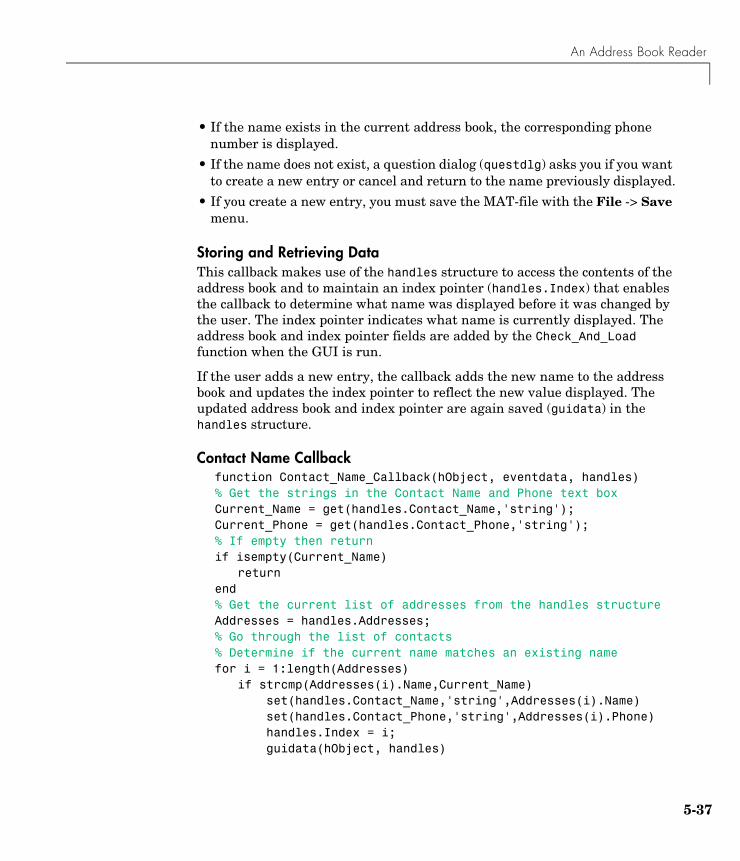
An Address Book Reader
5-37
• If the name exists in the current address book, the corresponding phone number is displayed.
• If the name does not exist, a question dialog (questdlg) asks you if you want to create a new entry or cancel and return to the name previously displayed.
• If you create a new entry, you must save the MAT-file with the File -> Save menu.
Storing and Retrieving DataThis callback makes use of the handles structure to access the contents of the address book and to maintain an index pointer (handles.Index) that enables the callback to determine what name was displayed before it was changed by the user. The index pointer indicates what name is currently displayed. The address book and index pointer fields are added by the Check_And_Load function when the GUI is run.
If the user adds a new entry, the callback adds the new name to the address book and updates the index pointer to reflect the new value displayed. The updated address book and index pointer are again saved (guidata) in the handles structure.
Contact Name Callbackfunction Contact_Name_Callback(hObject, eventdata, handles)% Get the strings in the Contact Name and Phone text boxCurrent_Name = get(handles.Contact_Name,'string');Current_Phone = get(handles.Contact_Phone,'string');% If empty then returnif isempty(Current_Name)
returnend% Get the current list of addresses from the handles structureAddresses = handles.Addresses;% Go through the list of contacts% Determine if the current name matches an existing namefor i = 1:length(Addresses)
if strcmp(Addresses(i).Name,Current_Name)set(handles.Contact_Name,'string',Addresses(i).Name)set(handles.Contact_Phone,'string',Addresses(i).Phone)handles.Index = i;guidata(hObject, handles)
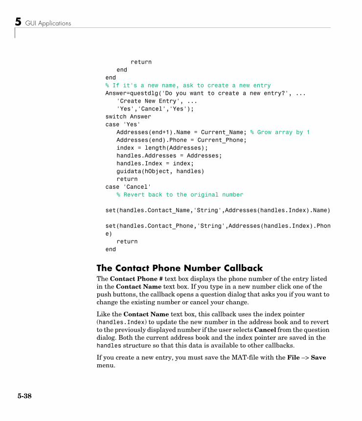
5 GUI Applications
5-38
returnend
end% If it's a new name, ask to create a new entryAnswer=questdlg('Do you want to create a new entry?', ...
'Create New Entry', ...'Yes','Cancel','Yes');
switch Answercase 'Yes'
Addresses(end+1).Name = Current_Name; % Grow array by 1Addresses(end).Phone = Current_Phone; index = length(Addresses);handles.Addresses = Addresses;handles.Index = index;guidata(hObject, handles)return
case 'Cancel'% Revert back to the original number
set(handles.Contact_Name,'String',Addresses(handles.Index).Name)
set(handles.Contact_Phone,'String',Addresses(handles.Index).Phone)
returnend
The Contact Phone Number CallbackThe Contact Phone # text box displays the phone number of the entry listed in the Contact Name text box. If you type in a new number click one of the push buttons, the callback opens a question dialog that asks you if you want to change the existing number or cancel your change.
Like the Contact Name text box, this callback uses the index pointer (handles.Index) to update the new number in the address book and to revert to the previously displayed number if the user selects Cancel from the question dialog. Both the current address book and the index pointer are saved in the handles structure so that this data is available to other callbacks.
If you create a new entry, you must save the MAT-file with the File –> Save menu.
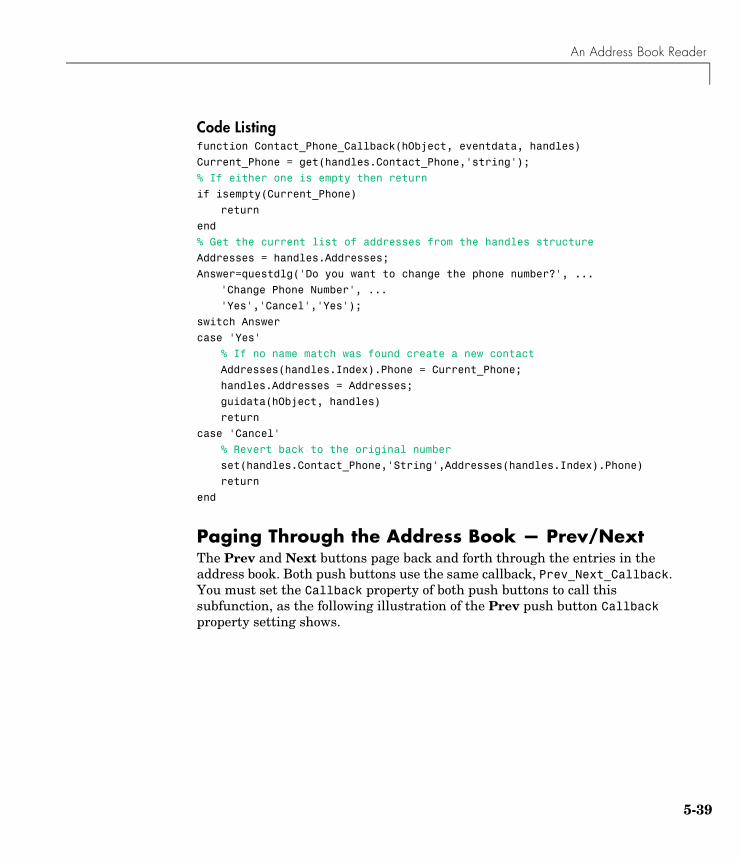
An Address Book Reader
5-39
Code Listingfunction Contact_Phone_Callback(hObject, eventdata, handles)
Current_Phone = get(handles.Contact_Phone,'string');
% If either one is empty then return
if isempty(Current_Phone)
return
end
% Get the current list of addresses from the handles structure
Addresses = handles.Addresses;
Answer=questdlg('Do you want to change the phone number?', ...
'Change Phone Number', ...
'Yes','Cancel','Yes');
switch Answer
case 'Yes'
% If no name match was found create a new contact
Addresses(handles.Index).Phone = Current_Phone;
handles.Addresses = Addresses;
guidata(hObject, handles)
return
case 'Cancel'
% Revert back to the original number
set(handles.Contact_Phone,'String',Addresses(handles.Index).Phone)
return
end
Paging Through the Address Book — Prev/NextThe Prev and Next buttons page back and forth through the entries in the address book. Both push buttons use the same callback, Prev_Next_Callback. You must set the Callback property of both push buttons to call this subfunction, as the following illustration of the Prev push button Callback property setting shows.
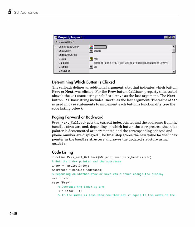
5 GUI Applications
5-40
Determining Which Button Is ClickedThe callback defines an additional argument, str, that indicates which button, Prev or Next, was clicked. For the Prev button Callback property (illustrated above), the Callback string includes 'Prev' as the last argument. The Next button Callback string includes 'Next' as the last argument. The value of str is used in case statements to implement each button’s functionality (see the code listing below).
Paging Forward or BackwardPrev_Next_Callback gets the current index pointer and the addresses from the handles structure and, depending on which button the user presses, the index pointer is decremented or incremented and the corresponding address and phone number are displayed. The final step stores the new value for the index pointer in the handles structure and saves the updated structure using guidata.
Code Listingfunction Prev_Next_Callback(hObject, eventdata,handles,str)
% Get the index pointer and the addresses
index = handles.Index;
Addresses = handles.Addresses;
% Depending on whether Prev or Next was clicked change the display
switch str
case 'Prev'
% Decrease the index by one
i = index - 1;
% If the index is less then one then set it equal to the index of the
An Address Book Reader
5-41
% last element in the Addresses array
if i < 1
i = length(Addresses);
end
case 'Next'
% Increase the index by one
i = index + 1;
% If the index is greater than the size of the array then point
% to the first item in the Addresses array
if i > length(Addresses)
i = 1;
end
end
% Get the appropriate data for the index in selected
Current_Name = Addresses(i).Name;
Current_Phone = Addresses(i).Phone;
set(handles.Contact_Name,'string',Current_Name)
set(handles.Contact_Phone,'string',Current_Phone)
% Update the index pointer to reflect the new index
handles.Index = i;
guidata(hObject, handles)
Saving Changes to the Address Book from the MenuWhen you make changes to an address book, you need to save the current MAT-file, or save it as a new MAT-file. The File submenus Save and Save As enable you to do this. These menus, created with the Menu Editor, use the same callback, Save_Callback.
The callback uses the menu Tag property to identify whether Save or Save As is the callback object (i.e., the object whose handle is passed in as the first argument to the callback function). You specify the menu’s Tag property with the Menu Editor.
Saving the Addresses StructureThe handles structure contains the Addresses structure, which you must save (handles.Addresses) as well as the name of the currently loaded MAT-file (handles.LastFile). When the user makes changes to the name or number, the Contact_Name_Callback or the Contact_Phone_Callback updates handles.Addresses.
5 GUI Applications
5-42
Saving the MAT-FileIf the user selects Save, the save command is called to save the current MAT-file with the new names and phone numbers.
If the user selects Save As, a dialog is displayed (uiputfile) that enables the user to select the name of an existing MAT-file or specify a new file. The dialog returns the selected filename and path. The final steps include
• Using fullfile to create a platform-independent pathname.
• Calling save to save the new data in the MAT-file.
• Updating the handles structure to contain the new MAT-file name.
• Calling guidata to save the handles structure.
Save_Callback Code Listingfunction Save_Callback(hObject, eventdata, handles)% Get the Tag of the menu selectedTag = get(hObject, 'Tag');% Get the address arrayAddresses = handles.Addresses;% Based on the item selected, take the appropriate actionswitch Tagcase 'Save'
% Save to the default addrbook fileFile = handles.LastFile;save(File,'Addresses')
case 'Save_As'% Allow the user to select the file name to save to[filename, pathname] = uiputfile( ...
{'*.mat';'*.*'}, ...'Save as');
% If 'Cancel' was selected then returnif isequal([filename,pathname],[0,0])
returnelse
% Construct the full path and saveFile = fullfile(pathname,filename);save(File,'Addresses')handles.LastFile = File;guidata(hObject, handles)
An Address Book Reader
5-43
endend
The Create New MenuThe Create New menu simply clears the Contact Name and Contact Phone # text fields to facilitate adding a new name and number. After making the new entries, the user must then save the address book with the Save or Save As menus. This callback sets the text String properties to empty strings:
function New_Callback(hObject, eventdata, handles)set(handles.Contact_Name,'String','')set(handles.Contact_Phone,'String','')
The Address Book Resize FunctionThe address book defines its own resize function. To use this resize function, you must set the Application Options dialog Resize behavior to User-specified, which in turn sets the figure’s ResizeFcn property to:
address_book('ResizeFcn',gcbo,[],guidata(gcbo))
Whenever the user resizes the figure, MATLAB calls the ResizeFcn subfunction in the address book M-file (address_book.m)
Behavior of the Resize FunctionThe resize function allows users to make the figure wider, to accommodate long names and numbers, but does not allow the figure to be made narrower than its original width. Also, users cannot change the height. These restrictions do not limit the usefulness of the GUI and simplify the resize function, which must maintain the proper proportions between the figure size and the components in the GUI.
When the user resizes the figure and releases the mouse, the resize function executes. At that point, the resized figure’s dimensions are saved. The following sections describe how the resize function handles the various possibilities.
Changing the WidthIf the new width is greater than the original width, set the figure to the new width.
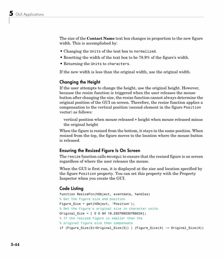
5 GUI Applications
5-44
The size of the Contact Name text box changes in proportion to the new figure width. This is accomplished by:
• Changing the Units of the text box to normalized.
• Resetting the width of the text box to be 78.9% of the figure’s width.
• Returning the Units to characters.
If the new width is less than the original width, use the original width.
Changing the HeightIf the user attempts to change the height, use the original height. However, because the resize function is triggered when the user releases the mouse button after changing the size, the resize function cannot always determine the original position of the GUI on screen. Therefore, the resize function applies a compensation to the vertical position (second element in the figure Position vector) as follows:
vertical position when mouse released + height when mouse released minus the original height
When the figure is resized from the bottom, it stays in the same position. When resized from the top, the figure moves to the location where the mouse button is released.
Ensuring the Resized Figure Is On ScreenThe resize function calls movegui to ensure that the resized figure is on screen regardless of where the user releases the mouse.
When the GUI is first run, it is displayed at the size and location specified by the figure Position property. You can set this property with the Property Inspector when you create the GUI.
Code Listingfunction ResizeFcn(hObject, eventdata, handles)
% Get the figure size and position
Figure_Size = get(hObject, 'Position');
% Set the figure's original size in character units
Original_Size = [ 0 0 94 19.230769230769234];
% If the resized figure is smaller than the
% original figure size then compensate
if (Figure_Size(3)<Original_Size(3)) | (Figure_Size(4) ~= Original_Size(4))
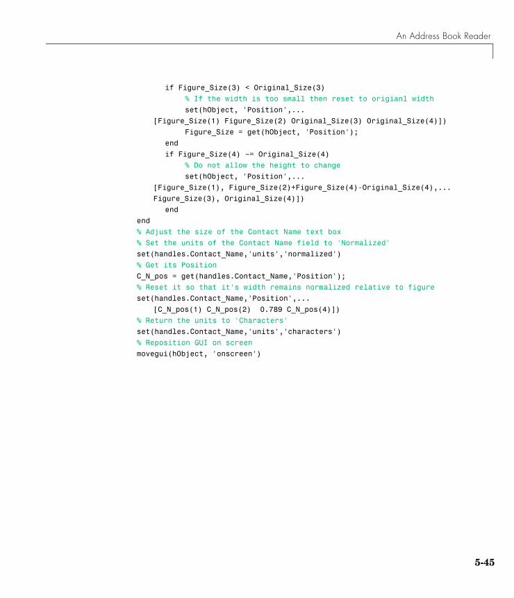
An Address Book Reader
5-45
if Figure_Size(3) < Original_Size(3)
% If the width is too small then reset to origianl width
set(hObject, 'Position',...
[Figure_Size(1) Figure_Size(2) Original_Size(3) Original_Size(4)])
Figure_Size = get(hObject, 'Position');
end
if Figure_Size(4) ~= Original_Size(4)
% Do not allow the height to change
set(hObject, 'Position',...
[Figure_Size(1), Figure_Size(2)+Figure_Size(4)-Original_Size(4),...
Figure_Size(3), Original_Size(4)])
end
end
% Adjust the size of the Contact Name text box
% Set the units of the Contact Name field to 'Normalized'
set(handles.Contact_Name,'units','normalized')
% Get its Position
C_N_pos = get(handles.Contact_Name,'Position');
% Reset it so that it's width remains normalized relative to figure
set(handles.Contact_Name,'Position',...
[C_N_pos(1) C_N_pos(2) 0.789 C_N_pos(4)])
% Return the units to 'Characters'
set(handles.Contact_Name,'units','characters')
% Reposition GUI on screen
movegui(hObject, 'onscreen')

5 GUI Applications
5-46
AWorking with Callbacks (Draft)
This chapter, in draft form, brings information regarding callbacks into one place. It introduces the concepts and mechanisms with which you work, and explains some basic techniques for programming your GUI's behavior. It is not yet complete, but you may find it useful, even in its current state, particularly if you are new to creating GUIs.
This chapter contains new information, but also duplicates information that can be found in various places throughout the rest of the book. In cases where information has not yet been included in the new chapter, links take you to the main part of the book.
Introduction to GUI Callbacks (p. A-3)
Defines callback and lists available callbacks.
GUI Files (p. A-7) Describes files needed for GUIDE-generated GUIs and suggests how you can organize your files as you create your GUI programmatically.
Associating Callbacks with Components (p. A-14)
Explains how you use component properties to associate callbacks with components.
Component and Figure Callbacks (p. A-17)
Describes callback syntax and arguments. For GUIDE users, explains how to add callbacks and change callback names.
Initialization Callbacks in GUIDE (p. A-23)
Describes callbacks you can use to initialize your GUI and write output to the command line.
Managing Application-Defined Data (p. A-27)
Describes the mechanisms for managing application-defined data. Discusses how you use each of these mechanisms for sharing data among a GUI’s callbacks.
A Working with Callbacks (Draft)
A-2
Properties That Control Component Behavior (p. A-35)
Reviews properties that you can use to control a GUI’s behavior.
Examples of Callbacks for GUI Components (p. A-40)
Brief code examples for the most commonly used components.
Introduction to GUI Callbacks
A-3
Introduction to GUI CallbacksAfter you have laid out your GUI, you need to program its behavior. The code you write controls how the GUI responds to events such as button clicks, menu item selection, window resizing, or the creation and deletion of components. This programming takes the form of a set of functions, called callbacks, for the GUI figure itself and for each component.
This chapter addresses the programming of GUIs created using GUIDE as well as those created programmatically. This section explains:
• “What Is a Callback?” on page A-3
• “Kinds of Callbacks” on page A-3
What Is a Callback?A callback is a function that you associate with a specific GUI component or with the GUI figure. It controls component behavior by performing some action in response to an event for that component. MATLAB invokes the callback in response to an appropriate event. As an example, suppose a GUI has a button that triggers the plotting of some data. When the user clicks the button, MATLAB calls the callback you associated with clicking that button, and the callback then gets the data and plots it.
A component can be any control device such as a push button or slider. It can also be a menu, a toolbar, a toolbar tool, or a container such as a panel or button group.
Kinds of CallbacksEach type of component has certain kinds of callbacks with which it can be associated. The possible kinds of callbacks are defined as properties of components. For example, a uipanel has four callback properties: ButtonDownFcn, CreateFcn, DeleteFcn, and ResizeFcn. You can, but are not required to, create a callback function for each of these properties. The GUI itself, which is a figure, also has certain kinds of callbacks with which it can be associated.
Each kind of callback has a triggering mechanism or event that causes it to be called. The following table lists the different kinds of callback properties, the components to which they apply, and the triggering mechanism.
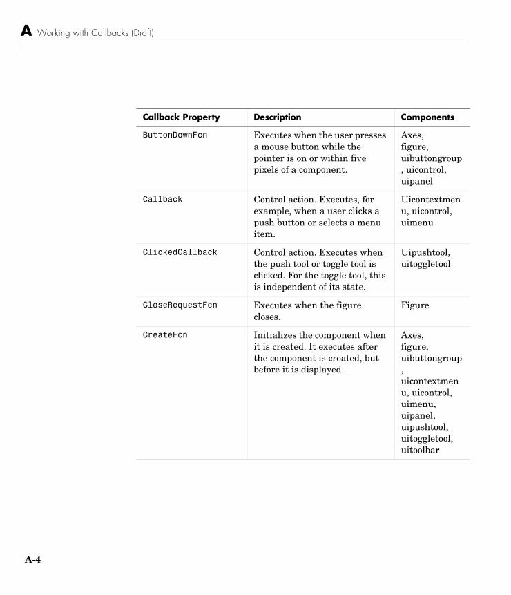
A Working with Callbacks (Draft)
A-4
Callback Property Description Components
ButtonDownFcn Executes when the user presses a mouse button while the pointer is on or within five pixels of a component.
Axes, figure, uibuttongroup, uicontrol, uipanel
Callback Control action. Executes, for example, when a user clicks a push button or selects a menu item.
Uicontextmenu, uicontrol, uimenu
ClickedCallback Control action. Executes when the push tool or toggle tool is clicked. For the toggle tool, this is independent of its state.
Uipushtool, uitoggletool
CloseRequestFcn Executes when the figure closes.
Figure
CreateFcn Initializes the component when it is created. It executes after the component is created, but before it is displayed.
Axes, figure, uibuttongroup, uicontextmenu, uicontrol, uimenu, uipanel, uipushtool, uitoggletool, uitoolbar
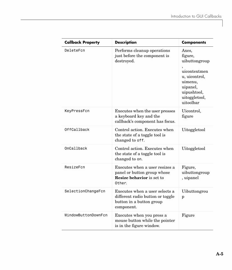
Introduction to GUI Callbacks
A-5
DeleteFcn Performs cleanup operations just before the component is destroyed.
Axes, figure, uibuttongroup, uicontextmenu, uicontrol, uimenu, uipanel, uipushtool, uitoggletool, uitoolbar
KeyPressFcn Executes when the user presses a keyboard key and the callback’s component has focus.
Uicontrol, figure
OffCallback Control action. Executes when the state of a toggle tool is changed to off.
Uitoggletool
OnCallback Control action. Executes when the state of a toggle tool is changed to on.
Uitoggletool
ResizeFcn Executes when a user resizes a panel or button group whose Resize behavior is set to Other.
Figure, uibuttongroup, uipanel
SelectionChangeFcn Executes when a user selects a different radio button or toggle button in a button group component.
Uibuttongroup
WindowButtonDownFcn Executes when you press a mouse button while the pointer is in the figure window.
Figure
Callback Property Description Components
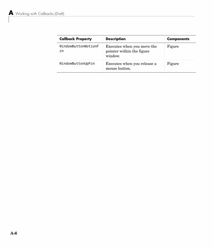
A Working with Callbacks (Draft)
A-6
WindowButtonMotionFcn
Executes when you move the pointer within the figure window.
Figure
WindowButtonUpFcn Executes when you release a mouse button.
Figure
Callback Property Description Components
GUI Files
A-7
GUI FilesIf you create your GUI using GUIDE, it automatically generates appropriate GUI files that contain the GUI layout and callbacks. If you create your GUI programmatically, it is up to you to create the files you need. These topics describe each case:
• “GUIDE M-Files and FIG-Files” on page A-7
• “Files for Programmatically Created GUIs” on page A-10
GUIDE M-Files and FIG-FilesGUIDE automatically generates two files for each GUI:
• A FIG-file that contains the layout of the GUI. This is a binary file and you cannot modify it except by changing the layout in GUIDE.
• An M-file that contains initialization code and templates for some callbacks that are needed to control GUI behavior.
Note that if your GUI includes ActiveX components, GUIDE also generates a file for each ActiveX component. See “ActiveX Controls” on page 4-17 for more information.
This topic discusses the following:
• “GUI File Creation” on page A-7
• “GUI M-File Structure” on page A-8
• “Adding Callbacks to an Existing GUI M-File” on page A-9
• “Changing Callback Names Assigned by GUIDE” on page A-19
• “Changing the Name of Your GUI” on page A-9
• “Converting a GUI to a Single M-File” on page A-9
GUI File CreationGUIDE creates the FIG-file and M-file the first time you save or run the GUI. You can save a GUI by selecting Save or Save as from the File menu, or by clicking the Save icon on the toolbar. You can run the GUI by selecting Run from the Tools menu or by clicking the Run icon on the toolbar. If you run the GUI without having saved it, GUIDE prompts you to save it.
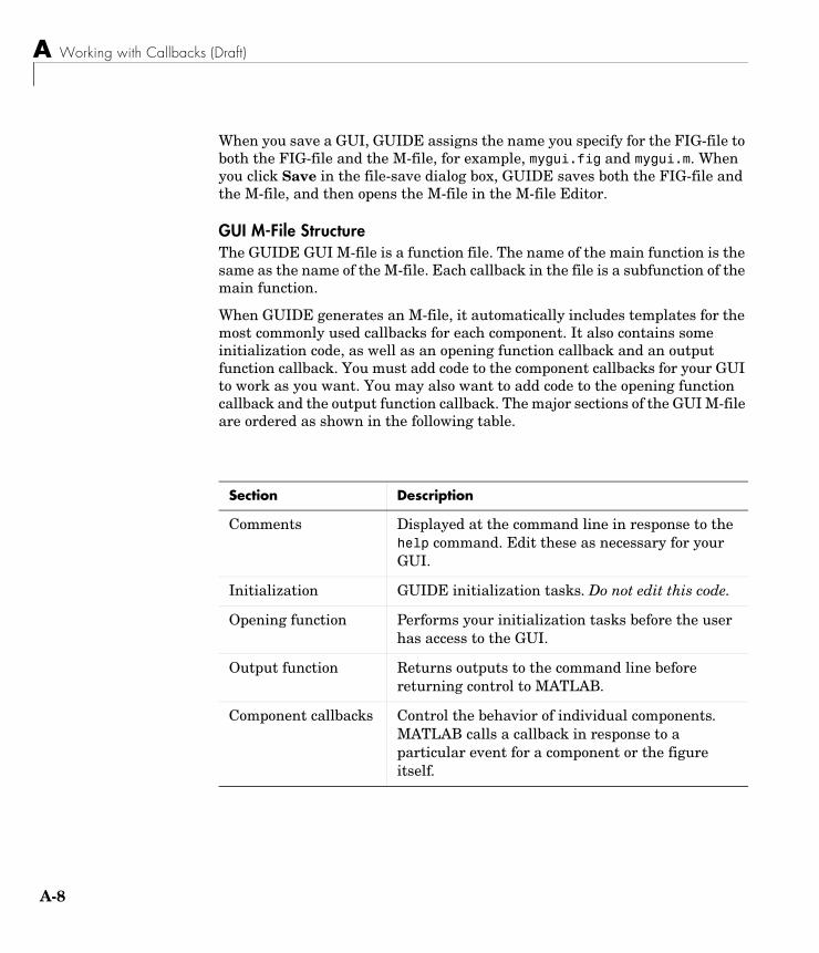
A Working with Callbacks (Draft)
A-8
When you save a GUI, GUIDE assigns the name you specify for the FIG-file to both the FIG-file and the M-file, for example, mygui.fig and mygui.m. When you click Save in the file-save dialog box, GUIDE saves both the FIG-file and the M-file, and then opens the M-file in the M-file Editor.
GUI M-File StructureThe GUIDE GUI M-file is a function file. The name of the main function is the same as the name of the M-file. Each callback in the file is a subfunction of the main function.
When GUIDE generates an M-file, it automatically includes templates for the most commonly used callbacks for each component. It also contains some initialization code, as well as an opening function callback and an output function callback. You must add code to the component callbacks for your GUI to work as you want. You may also want to add code to the opening function callback and the output function callback. The major sections of the GUI M-file are ordered as shown in the following table.
Section Description
Comments Displayed at the command line in response to the help command. Edit these as necessary for your GUI.
Initialization GUIDE initialization tasks. Do not edit this code.
Opening function Performs your initialization tasks before the user has access to the GUI.
Output function Returns outputs to the command line before returning control to MATLAB.
Component callbacks Control the behavior of individual components. MATLAB calls a callback in response to a particular event for a component or the figure itself.
GUI Files
A-9
Adding Callbacks to an Existing GUI M-FileWithin GUIDE, you can add a callback subfunction to the GUI M-file in one of two ways:
• Click the right mouse button while the component is selected to display the Layout Editor context menu. Select the desired callback from the View callbacks submenu. GUIDE adds the callback template to the GUI M-file and opens the M-file for editing at the callback it just added.
• With the component selected, select View callbacks from the View menu. GUIDE adds the callback template to the GUI M-file and opens the M-file for editing at the callback you just added.
Note In either case, if you select a callback that already exists in the GUI M-file, GUIDE opens the M-file for editing at the callback you select.
Changing the Name of Your GUIThe name of your GUI is the same as the name of its FIG-file and M-file. To change the name of your GUI, you must change both these file names.
In the GUIDE Layout Editor File menu, use Save As to rename the GUI FIG-file. In response, GUIDE renames both the FIG-file and the M-file. GUIDE also updates the callback properties with the new file name, as well as all instances of the file name in the body of the M-file.
Converting a GUI to a Single M-FileYou can convert a GUI that was created as a FIG-file and an M-file using GUIDE to a single M-file that does not require a FIG-file. This enables you to
• View the layout code for the GUI
• Run the GUI in MATLAB 6.1
Note If the GUI includes a container component such as a panel or button group, you will not be able to run it in MATLAB versions earlier than 7.0.
A Working with Callbacks (Draft)
A-10
You can perform this conversion by exporting your GUI using the following steps:
1 Save the GUI in GUIDE, if you have not already done so.
2 Select Export from the File menu.
If you changed the GUI since you last saved it, this opens a dialog informing you that exporting will save changes to your figure and M-file, and asking if you want to continue.
3 Save the exported M-file in the Save As dialog. By default, GUIDE gives the exported M-file the name of the GUI M-file with _export appended.
Note If you save a large data set in the GUI figure or in a uicontrol, GUIDE might also export a MAT-file containing the data. For example, you might have saved the data in a figure or uicontrol UserData property, or in a figure Colormap property. The name of the MAT-file is the same as the exported M-file except for the extension .mat.
Files for Programmatically Created GUIsWhen you create a GUI programmatically, these are two approaches you can use to structure your GUI files:
• “Single M-File Using GUIDE as a Model” on page A-10
• “Single M-File Using Nested Functions” on page A-12
Single M-File Using GUIDE as a ModelIn this approach, the file is ordered in the following sections:
1 Comments that are displayed in response to the MATLAB help command.
2 Command to make the figure invisible so the user can’t see it being constructed.
3 Construction of components and menus. Don’t set the callback properties yet.
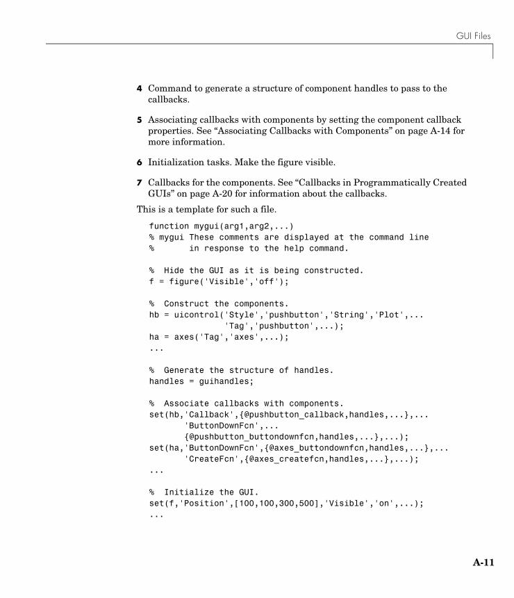
GUI Files
A-11
4 Command to generate a structure of component handles to pass to the callbacks.
5 Associating callbacks with components by setting the component callback properties. See “Associating Callbacks with Components” on page A-14 for more information.
6 Initialization tasks. Make the figure visible.
7 Callbacks for the components. See “Callbacks in Programmatically Created GUIs” on page A-20 for information about the callbacks.
This is a template for such a file.
function mygui(arg1,arg2,...)% mygui These comments are displayed at the command line % in response to the help command.
% Hide the GUI as it is being constructed.f = figure('Visible','off');
% Construct the components.hb = uicontrol('Style','pushbutton','String','Plot',... 'Tag','pushbutton',...);ha = axes('Tag','axes',...);...
% Generate the structure of handles.handles = guihandles;
% Associate callbacks with components.set(hb,'Callback',{@pushbutton_callback,handles,...},... 'ButtonDownFcn',... {@pushbutton_buttondownfcn,handles,...},...);set(ha,'ButtonDownFcn',{@axes_buttondownfcn,handles,...},... 'CreateFcn',{@axes_createfcn,handles,...},...);...
% Initialize the GUI.set(f,'Position',[100,100,300,500],'Visible','on',...);...
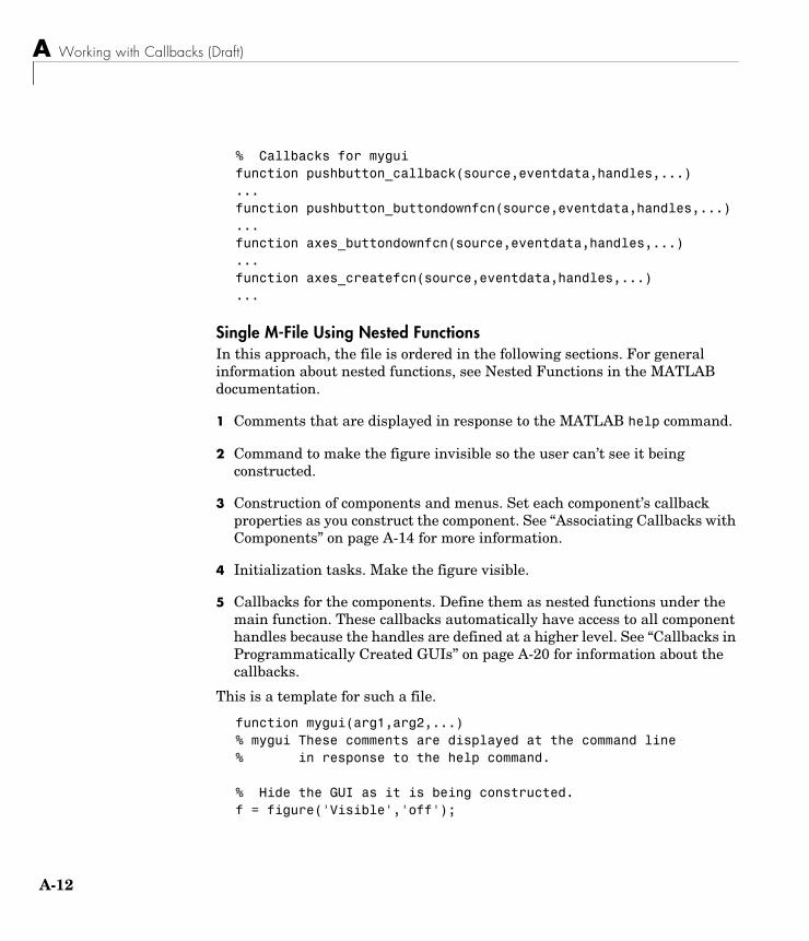
A Working with Callbacks (Draft)
A-12
% Callbacks for myguifunction pushbutton_callback(source,eventdata,handles,...)...function pushbutton_buttondownfcn(source,eventdata,handles,...)...function axes_buttondownfcn(source,eventdata,handles,...)...function axes_createfcn(source,eventdata,handles,...)...
Single M-File Using Nested FunctionsIn this approach, the file is ordered in the following sections. For general information about nested functions, see Nested Functions in the MATLAB documentation.
1 Comments that are displayed in response to the MATLAB help command.
2 Command to make the figure invisible so the user can’t see it being constructed.
3 Construction of components and menus. Set each component’s callback properties as you construct the component. See “Associating Callbacks with Components” on page A-14 for more information.
4 Initialization tasks. Make the figure visible.
5 Callbacks for the components. Define them as nested functions under the main function. These callbacks automatically have access to all component handles because the handles are defined at a higher level. See “Callbacks in Programmatically Created GUIs” on page A-20 for information about the callbacks.
This is a template for such a file.
function mygui(arg1,arg2,...)% mygui These comments are displayed at the command line % in response to the help command.
% Hide the GUI as it is being constructed.f = figure('Visible','off');
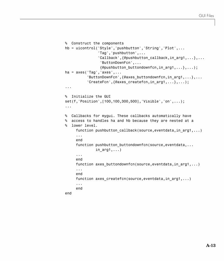
GUI Files
A-13
% Construct the componentshb = uicontrol('Style','pushbutton','String','Plot',... 'Tag','pushbutton',... 'Callback',{@pushbutton_callback,in_arg1,...},... 'ButtonDownFcn',... {@pushbutton_buttondownfcn,in_arg1,...},...);ha = axes('Tag','axes',... 'ButtonDownFcn',{@axes_buttondownfcn,in_arg1,...},... 'CreateFcn',{@axes_createfcn,in_arg1,...},...);...
% Initialize the GUIset(f,'Position',[100,100,300,500],'Visible','on',...);...
% Callbacks for mygui. These callbacks automatically have % access to handles ha and hb because they are nested at a % lower level. function pushbutton_callback(source,eventdata,in_arg1,...) ... end function pushbutton_buttondownfcn(source,eventdata,... in_arg1,...) ... end function axes_buttondownfcn(source,eventdata,in_arg1,...) ... end function axes_createfcn(source,eventdata,in_arg1,...) ... endend
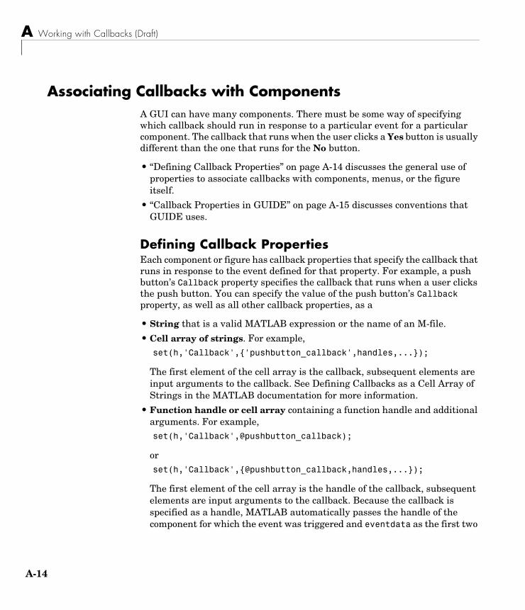
A Working with Callbacks (Draft)
A-14
Associating Callbacks with ComponentsA GUI can have many components. There must be some way of specifying which callback should run in response to a particular event for a particular component. The callback that runs when the user clicks a Yes button is usually different than the one that runs for the No button.
• “Defining Callback Properties” on page A-14 discusses the general use of properties to associate callbacks with components, menus, or the figure itself.
• “Callback Properties in GUIDE” on page A-15 discusses conventions that GUIDE uses.
Defining Callback PropertiesEach component or figure has callback properties that specify the callback that runs in response to the event defined for that property. For example, a push button’s Callback property specifies the callback that runs when a user clicks the push button. You can specify the value of the push button’s Callback property, as well as all other callback properties, as a
• String that is a valid MATLAB expression or the name of an M-file.
• Cell array of strings. For example, set(h,'Callback',{'pushbutton_callback',handles,...});
The first element of the cell array is the callback, subsequent elements are input arguments to the callback. See Defining Callbacks as a Cell Array of Strings in the MATLAB documentation for more information.
• Function handle or cell array containing a function handle and additional arguments. For example, set(h,'Callback',@pushbutton_callback);
orset(h,'Callback',{@pushbutton_callback,handles,...});
The first element of the cell array is the handle of the callback, subsequent elements are input arguments to the callback. Because the callback is specified as a handle, MATLAB automatically passes the handle of the component for which the event was triggered and eventdata as the first two
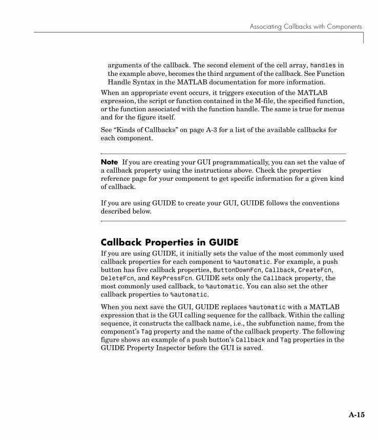
Associating Callbacks with Components
A-15
arguments of the callback. The second element of the cell array, handles in the example above, becomes the third argument of the callback. See Function Handle Syntax in the MATLAB documentation for more information.
When an appropriate event occurs, it triggers execution of the MATLAB expression, the script or function contained in the M-file, the specified function, or the function associated with the function handle. The same is true for menus and for the figure itself.
See “Kinds of Callbacks” on page A-3 for a list of the available callbacks for each component.
Note If you are creating your GUI programmatically, you can set the value of a callback property using the instructions above. Check the properties reference page for your component to get specific information for a given kind of callback.
If you are using GUIDE to create your GUI, GUIDE follows the conventions described below.
Callback Properties in GUIDEIf you are using GUIDE, it initially sets the value of the most commonly used callback properties for each component to %automatic. For example, a push button has five callback properties, ButtonDownFcn, Callback, CreateFcn, DeleteFcn, and KeyPressFcn. GUIDE sets only the Callback property, the most commonly used callback, to %automatic. You can also set the other callback properties to %automatic.
When you next save the GUI, GUIDE replaces %automatic with a MATLAB expression that is the GUI calling sequence for the callback. Within the calling sequence, it constructs the callback name, i.e., the subfunction name, from the component’s Tag property and the name of the callback property. The following figure shows an example of a push button’s Callback and Tag properties in the GUIDE Property Inspector before the GUI is saved.
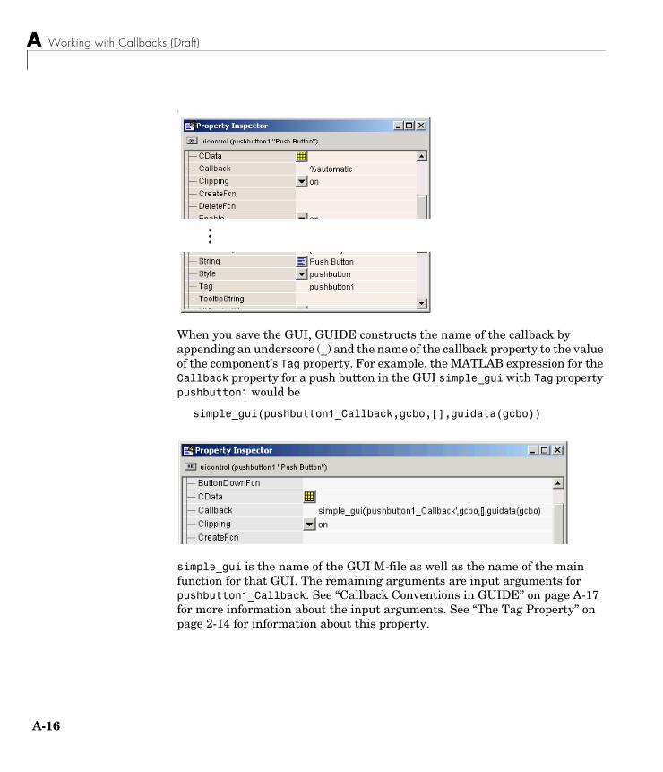
A Working with Callbacks (Draft)
A-16
-
When you save the GUI, GUIDE constructs the name of the callback by appending an underscore (_) and the name of the callback property to the value of the component’s Tag property. For example, the MATLAB expression for the Callback property for a push button in the GUI simple_gui with Tag property pushbutton1 would be
simple_gui(pushbutton1_Callback,gcbo,[],guidata(gcbo))
simple_gui is the name of the GUI M-file as well as the name of the main function for that GUI. The remaining arguments are input arguments for pushbutton1_Callback. See “Callback Conventions in GUIDE” on page A-17 for more information about the input arguments. See “The Tag Property” on page 2-14 for information about this property.
...
Component and Figure Callbacks
A-17
Component and Figure CallbacksThis section provides general information about callbacks that are associated with components within a GUI, as well as with figure objects. It first explains the conventions that GUIDE uses, then continues by discussing concerns you must consider if you are creating a GUI programmatically.
• “Callback Conventions in GUIDE” on page A-17
• “Callbacks in Programmatically Created GUIs” on page A-20
See “Examples of Callbacks for GUI Components” on page A-40 for information about callbacks for some specific components.
Callback Conventions in GUIDEGUIDE defines conventions for callback syntax and arguments. These conventions enable GUIDE to provide commonly used information to each callback automatically.
• “Syntax and Arguments” on page A-17
• “Changing Callback Names Assigned by GUIDE” on page A-19
Syntax and ArgumentsThe GUIDE template for a component callback is similar to this one for a uicontrol of style pushbutton.
% --- Executes on button press in pushbutton1.function pushbutton1_Callback(hObject, eventdata, handles) %#ok% hObject handle to pushbutton1 (see GCBO)% eventdata reserved - to be defined in a future version of MATLAB% handles structure with handles and user data (see GUIDATA)
...
The first comment line describes the event that triggers execution of the callback. Other comments describe the input arguments.
A Working with Callbacks (Draft)
A-18
Note You can avoid automatic generation of the callback comment lines for new callbacks. In the Preferences dialog box, select GUIDE and uncheck the Add comments for newly generated callback functions preference.
The template also includes the function definition. Insert your code after the last comment.
Function Definition. GUIDE creates the callback name by appending an underscore (_) and the name of the callback property to the component’s Tag property. In the example above, pushbutton1 is the Tag property for the push button, and Callback is one of the push button’s callback properties. See “Associating Callbacks with Components” on page A-14 for more information.
Input Arguments. All callbacks in the GUI M-file have the following input arguments:
• hObject — Handle of the object for which the callback was triggered.
• eventdata — Reserved for later use.
• handles — Structure that contains the handles of all the objects in the figure. It may also contain application-defined data.
The Handles Structure. For a GUI that contains an edit text, a uipanel, a pop-up menu, and a push button, the handles structure that GUIDE creates originally looks similar to this. GUIDE uses a component’s Tag property to name the structure element for its handle.
handles = figure1: 160.0011 edit1: 9.0020 uipanel1: 8.0017 popupmenu1: 7.0018 pushbutton1: 161.0011 output: 160.0011
GUIDE stores and maintains the handles structure. If you change any of these variables, or make explicit changes to the handles structure, you must save the handles structure before exiting the callback. To do this, you must use the command
Component and Figure Callbacks
A-19
guidata(hObject,handles);
See “Managing GUI Data with the Handles Structure” on page 4-27 and the guidata reference page for general information about the handles structure.
See “Managing Application-Defined Data” on page A-27 for information about using the handles structure.
Note The guidata function can manage only one variable. For GUIs created with GUIDE, this is the handles structure. If your GUI M-file was created by GUIDE, do not call guidata with any data other than handles. If you do, you will overwrite handles and your GUI will not work. If you need to store other data with your GUI, you can add it to the handles structure. See “Adding Fields to a Data Structure” on page A-30 for information about adding fields to this structure.
Changing Callback Names Assigned by GUIDEYou can change callback names assigned by GUIDE in either of the following ways:
• “Changing the Tag Property” on page A-19
• “Changing the Callback Property” on page A-20
In either case, see “Setting Component Properties — The Property Inspector” on page 3-44 for information about using the Property Inspector to change property values.
Changing the Tag Property. You can change a Tag property to give a component’s callbacks a more meaningful name, e.g., you might change the Tag property from pushbutton1 to closebutton. If possible, change the Tag property before saving the GUI, then GUIDE automatically uses the new value when it names the callbacks. However, if you change the Tag property after saving the GUI, GUIDE updates the following items according to the new Tag, provided that all components have distinct tags:
• The component’s callback functions in the M-file
• The value of the component’s callback properties, which you can view in the Property Inspector
A Working with Callbacks (Draft)
A-20
• References in the M-file to the field of the handles structure that contains the component’s handle. See “Input Arguments” on page A-18 for more information about the handles structure.
Changing the Callback Property. To rename a particular callback subfunction without changing the Tag property,
• Replace the name string in the callback property with the new name. For example, if the value of the callback property for a push button in an untitled GUI is mygui('pushbutton1_Callback',gcbo,[],guidata(gcbo))
the string pushbutton1_Callback is the name of the callback function. Change the name to the desired name, for example, closebutton_Callback.
• Update all instances of the callback function name in the M-file.
• Update references in the M-file to the field of the handles structure that contains the component's handle. See “Input Arguments” on page A-18 for more information about the handles structure.
Callbacks in Programmatically Created GUIsAlthough you may eventually want to define your own syntactical conventions, the following provides a good place to start.
Function DefinitionYour function definition could look something like this:
% Description of event that triggers callback execution.function pushbutton1_Callback(source, eventdata, handles,...) ...
The comment line describes the event that triggers execution of the callback.
To help you remember the component and callback property with which this callback is associated, construct the callback name by appending an underscore (_) and the name of the callback property to the component’s Tag property. In the example above, pushbutton1 is the Tag property for the push button, and Callback is one of the push button’s callback properties. See “Associating Callbacks with Components” on page A-14 for more information.
Component and Figure Callbacks
A-21
Input ArgumentsIf you use a handle to specify the callback in the component callback property, i.e., @pushbutton_callback as shown here
set(h,'Callback',{@pushbutton_callback,handles,...})
MATLAB automatically passes the handle of the component for which the event was triggered and eventdata as the first two arguments of the callback. The function definition line for your callback must account for these two arguments. The second element of the cell array, handles in the example above, becomes the third argument of the callback. For example,
function pushbutton1_callback(source,eventdata,handles,...)
The input arguments are defined as:
• source — Handle of the object for which the callback was triggered.
• eventdata — Reserved for later use.
Note Three eventdata fields are defined for use with button groups. These fields enable you to determine the previous and current radio or toggle button selections maintained by the button group. See SelectionChangeFcn in the Uibuttongroup Properties for more information.
• handles — Structure you create with the guihandles function, prior to setting the component callback properties, that contains the handles of all the objects in the figure. It may also contain application-defined data.
Note If you are using nested functions, you do not need this argument to access the component handles. See “Files for Programmatically Created GUIs” on page A-10 for more information.
For a GUI that contains an edit text, a uipanel, a popup menu, and a push button, the handles structure you create with guihandles looks similar to this. guihandles uses the component Tag properties to name the elements of the structure.handles =
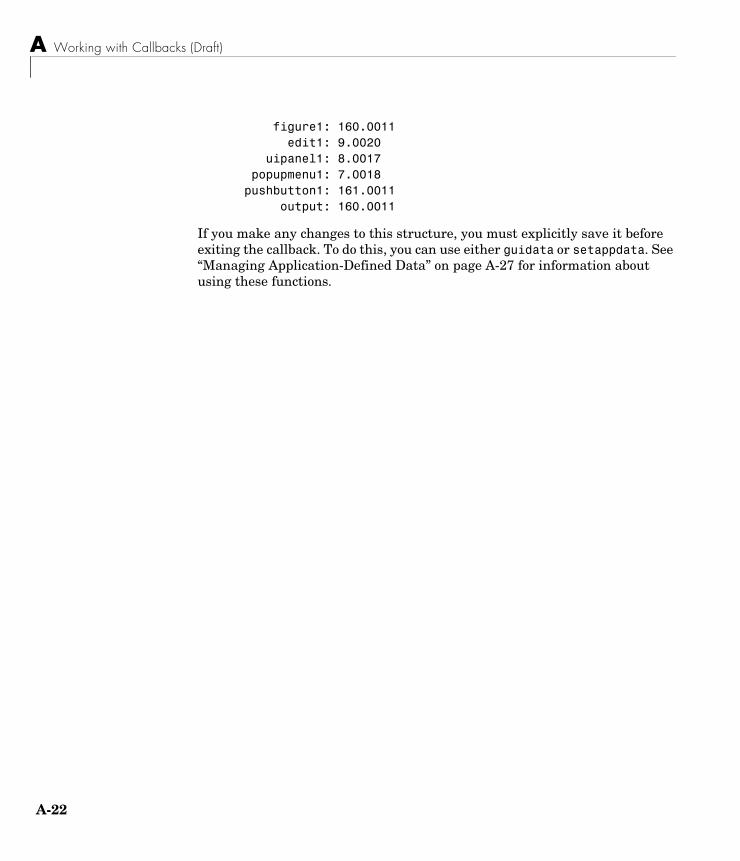
A Working with Callbacks (Draft)
A-22
figure1: 160.0011 edit1: 9.0020 uipanel1: 8.0017 popupmenu1: 7.0018 pushbutton1: 161.0011 output: 160.0011
If you make any changes to this structure, you must explicitly save it before exiting the callback. To do this, you can use either guidata or setappdata. See “Managing Application-Defined Data” on page A-27 for information about using these functions.
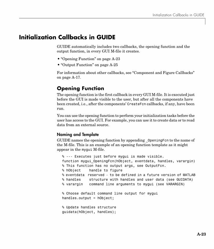
Initialization Callbacks in GUIDE
A-23
Initialization Callbacks in GUIDEGUIDE automatically includes two callbacks, the opening function and the output function, in every GUI M-file it creates.
• “Opening Function” on page A-23
• “Output Function” on page A-25
For information about other callbacks, see “Component and Figure Callbacks” on page A-17.
Opening FunctionThe opening function is the first callback in every GUI M-file. It is executed just before the GUI is made visible to the user, but after all the components have been created, i.e., after the components’ CreateFcn callbacks, if any, have been run.
You can use the opening function to perform your initialization tasks before the user has access to the GUI. For example, you can use it to create data or to read data from an external source.
Naming and TemplateGUIDE names the opening function by appending _OpeningFcn to the name of the M-file. This is an example of an opening function template as it might appear in the mygui M-file.
% --- Executes just before mygui is made visible.function mygui_OpeningFcn(hObject, eventdata, handles, varargin)% This function has no output args, see OutputFcn.% hObject handle to figure% eventdata reserved - to be defined in a future version of MATLAB% handles structure with handles and user data (see GUIDATA)% varargin command line arguments to mygui (see VARARGIN) % Choose default command line output for myguihandles.output = hObject; % Update handles structureguidata(hObject, handles);
A Working with Callbacks (Draft)
A-24
% UIWAIT makes mygui wait for user response (see UIRESUME)% uiwait(handles.mygui);
In this template:
• handles.output = hObject saves the handle of the figure, i.e., the handle of the GUI, for later access by the output function. For more information about the output function, see “Output Function” on page A-25.
• guidata(hObject,handles) saves the handles structure. You must use guidata to save any changes that you make to the handles structure. It is not sufficient just to set the value of a handles field. See “Managing GUI Data with the Handles Structure” on page 4-27 and “The Handles Structure” on page A-18 for more information.
• uiwait(handles.mygui), initially commented out, blocks GUI execution until uiresume is called or the GUI is deleted. Note that uiwait allows the user access to other MATLAB windows to obtain information. Remove the comment symbol for this statement if you do want the GUI to be blocking when it opens. See “Controlling Figure Window Behavior” on page 4-40 and “Example: Using the Modal Dialog to Confirm an Operation” on page 4-42 for more information.
Input ArgumentsThe opening function has four input arguments hObject, eventdata, handles, and varargin. The first three are the same as described in “Component and Figure Callbacks” on page A-17. varargin enables you to pass arguments to the opening function from the command line. For more information about varargin, see the varargin reference page and Passing Variable Numbers of Arguments in the MATLAB documentation.
All command line arguments are passed to the opening function via varargin. If you open the GUI with a property name/property value pair as arguments, the GUI opens with the property set to the specified value. For example, my_gui('Position', [71.8 44.9 74.8 19.7]) opens the GUI at the specified position, since Position is a valid figure property.
If the input argument is not a valid figure property, you must add code to the opening function to make use of the argument. For an example, look at the opening function for the modal question dialog template. The added code enables you to open the modal dialog with the syntax
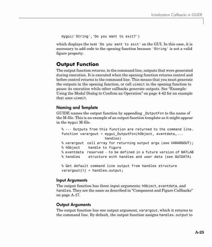
Initialization Callbacks in GUIDE
A-25
mygui('String','Do you want to exit?')
which displays the text 'Do you want to exit' on the GUI. In this case, it is necessary to add code to the opening function because 'String' is not a valid figure property.
Output FunctionThe output function returns, to the command line, outputs that were generated during execution. It is executed when the opening function returns control and before control returns to the command line. This means that you must generate the outputs in the opening function, or call uiwait in the opening function to pause its execution while other callbacks generate outputs. See “Example: Using the Modal Dialog to Confirm an Operation” on page 4-42 for an example that uses uiwait.
Naming and TemplateGUIDE names the output function by appending _OutputFcn to the name of the M-file. This is an example of an output function template as it might appear in the mygui M-file.
% --- Outputs from this function are returned to the command line.function varargout = mygui_OutputFcn(hObject, eventdata,... handles)% varargout cell array for returning output args (see VARARGOUT);% hObject handle to figure% eventdata reserved - to be defined in a future version of MATLAB% handles structure with handles and user data (see GUIDATA) % Get default command line output from handles structurevarargout{1} = handles.output;
Input ArgumentsThe output function has three input arguments: hObject, eventdata, and handles. They are the same as described in “Component and Figure Callbacks” on page A-17.
Output ArgumentsThe output function has one output argument, varargout, which it returns to the command line. By default, the output function assigns handles.output to
A Working with Callbacks (Draft)
A-26
varargout. So the default output is the handle to the GUI, which was assigned to handles.output in the opening function.
You can change the output by:
• Changing the value of handles.output. It can be any valid MATLAB value including a structure or cell array.
• Adding output arguments to varargout.
varargout is a cell array. It can contain any number of output arguments. By default, GUIDE creates just one output argument, handles.output. To create an additional output argument, create a new field in the handles structure and add it to varargout using a command similar tovarargout{2} = handles.second_output;
Managing Application-Defined Data
A-27
Managing Application-Defined DataMost GUIs generate or use data that is specific to the application. This topic describes the mechanisms for managing application-defined data, and discusses how you use each of these mechanisms for sharing data among a GUI’s callbacks.
Note See “Callback Conventions in GUIDE” on page A-17 for important information about using application data in GUIDE.
The following topics explain these mechanisms and describe their use:
• “Mechanisms for Managing Data” on page A-27
• “Adding Fields to a Data Structure” on page A-30
• “Sharing Data Among a GUI’s Callbacks” on page A-31
Mechanisms for Managing DataThis section explains the three mechanisms that are provided for managing data in the GUI environment. They provide a way for applications to save and retrieve data stored with the GUI.
• “GUI Data” on page A-27
• “Application Data” on page A-29
• “UserData Property” on page A-30
The GUI data and application data mechanisms are similar but GUI data can be simpler to use. You can use either or both in your GUI, whether you create it using GUIDE or create it programmatically. The UserData property can also hold application-defined data.
GUI DataThe guidata function can store a variable as GUI data, or retrieve the value of GUI data. GUI data is always associated with the GUI figure. It is available to all callbacks of all components of the GUI. If you specify a component handle when you save or retrieve GUI data, MATLAB automatically associates the data with the component’s parent figure.
A Working with Callbacks (Draft)
A-28
GUI data can contain only one variable at any time. Writing GUI data overwrites the existing GUI data. For this reason, GUI data is usually defined to be a structure to which you can add fields as you need them.
GUI data provides application developers with a convenient interface to a figure’s application data:
• You do not need to create and maintain a hard-coded name for the data throughout your source code.
• You can access the data from within a callback routine using the component's handle, without needing to find the figure handle. If you are creating the GUI programmatically, you can get the handle of the object whose callback is currently executing by calling gcbo. For GUIDE users, the object handle is automatically passed to each callback as hObject.
guidata is particularly useful in conjunction with guihandles, which creates a structure containing the handles of all the components in a GUI.
Note GUIDE uses guidata to store and maintain the handles structure, which contains the handles of all components in the GUI. The GUIDE templates also use the handles structure to store application-defined data.
In a GUIDE-generated M-file, do not use guidata to store any data other than handles. If you do, you may overwrite the handles structure and your GUI will not work. If you need to store other data with your GUI, you can add it to the handles structure. For more information, see “Managing GUI Data with the Handles Structure” on page 4-27 and “Adding Fields to a Data Structure” on page A-30.
To change GUI data in an M-file not generated by GUIDE:
1 Get a copy of the data with the command mydata = guidata(object_handle). Although GUI data is associated with the figure, object_handle can be the handle of the figure or any component in the figure.
2 Make the desired changes to mydata.
Managing Application-Defined Data
A-29
3 Save the changed version of data with the command guidata(object_handle,mydata).
To change GUI data in an M-file generated by GUIDE:
1 Make the desired changes to the handles structure that is automatically passed as an argument to every callback.
2 Save the changed version of handles with the command guidata(hObject,handles). The input argument hObject is the handle of the object for which the callback is executing.
Application DataApplication data provides a way for applications to save and retrieve data associated with an object. For a GUI, this is usually the GUI figure object but can also be any component. The data is stored as name/value pairs. Application data enables you to create what are essentially user-defined properties for an object.
The following table summarizes the functions that provide access to application data. For more detailed information, see the individual function reference pages.
Functions for Managing Application Data
Function Purpose
setappdata Specify named application data for an object. The object does not have to be a figure. You can specify more than one named application data for an object. However, each name must be unique for that object and can be associated with only one value, usually a structure.
getappdata Retrieve named application data. To retrieve named application data, you must know the name associated with the application data and the handle of the object with which it is associated.
isappdata True if the named application data exists.
rmappdata Remove the named application data.

A Working with Callbacks (Draft)
A-30
Note that if you are creating your GUI programmatically, you can store the structure of handles returned by guihandles as application data. You do not have to store it as GUI data. If you are using GUIDE you should always save the handles structure as GUI data.
UserData PropertyAll GUI components, menus, and the figure have a UserData property. You can assign any valid MATLAB value to the UserData property. To retrieve the data, a callback must know the handle of the component with which the data is associated.
Adding Fields to a Data StructureGUI data and application data are usually defined as structures to enable you to add fields as necessary. To add a field to a GUI data or application data structure:
1 Use guidata or getappdata, as appropriate, to retrieve the data structure. If it was saved with guidata, it has no name and you must use guidata to retrieve it. If it was saved with setappdata, you must know its name and the object with which it is associated, and you must use getappdata to retrieve it.
If you are using GUIDE, GUI data in the form of the handles structure is passed as an argument to every callback. You do not have to retrieve the handles structure before changing it.
2 Assign a value to the new field. This adds the field to the structure. For example
handles.number_errors = 0;
adds the field number_errors to the structure handles and sets it to 0.
3 Use guidata or setappdata, as appropriate, to save the data. This example saves the handles structure using guidata.
guidata(hObject,handles)
In a GUIDE-generated M-file, hObject is the handle of the object for which the callback was triggered. It is passed automatically to every callback.
Managing Application-Defined Data
A-31
Sharing Data Among a GUI’s CallbacksYou can use GUI data, application data, and the UserData property to share data among a GUI’s callbacks. See “Mechanisms for Managing Data” on page A-27 for information about these data forms.
GUI DataGUI data is accessible to all callbacks of the GUI. A callback for one component can set a value in GUI data which can then be read by a callback for another component. If GUI data is a structure, then both callbacks must know the name of the field that is being used to store the data.
For GUIDE users, arguments that are passed from the command line to the opening function can be made available to the callbacks if the opening function adds them to the handles structure.
Application DataApplication data can be associated with any object. In a GUI, if you associate it with the figure, all the GUI’s callbacks can easily retrieve it by name, using the figure handle. You can also associate application data with individual components or menus.
To access application data, a callback must know the name of the data and the handle of the component with which it is associated.
Use the functions setappdata, getappdata, isappdata, and rmappdata to manage application data.
UserData PropertyUse the get function to retrieve application-defined data from a component’s UserData property. You must know the handle of the component to retrieve the data. If you are using GUIDE, you can retrieve the component handle from the handles structure. If you have created your GUI programmatically, you can use the guihandles function to generate a structure of handles for your GUI.
Example: Using GUI Data in a GUIDE-Generated GUIThis example uses GUI data to pass data between a slider and an editable text box in a GUI created using GUIDE. The GUI behavior is as follows:
• When a user moves the slider, the text box displays the slider’s current value.
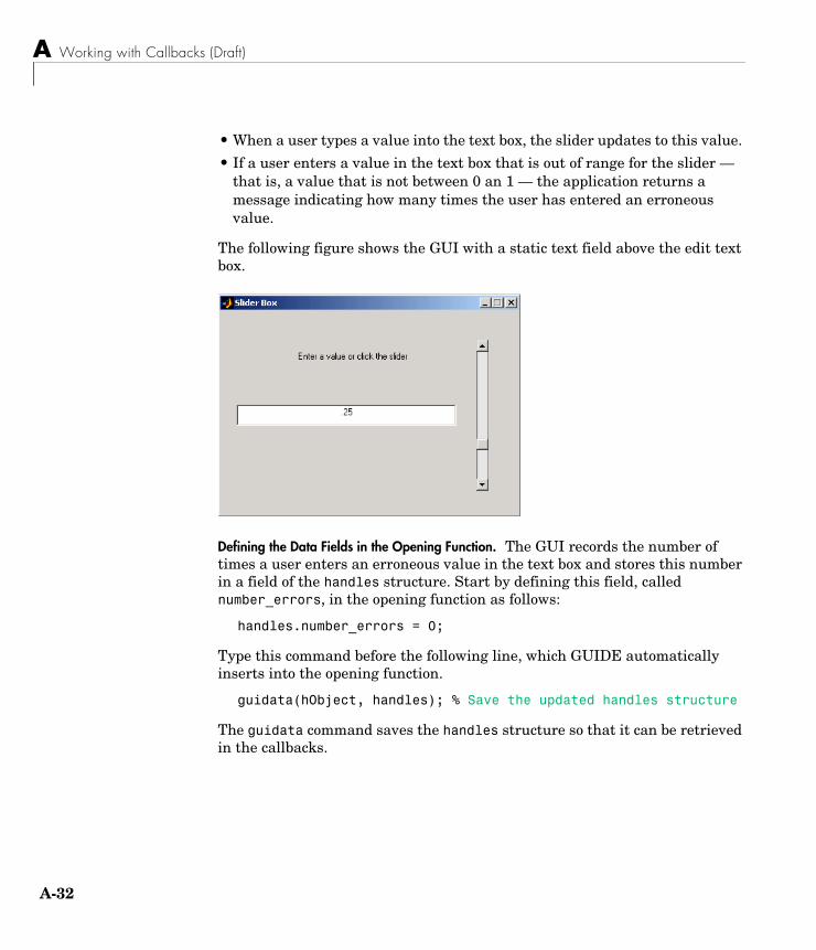
A Working with Callbacks (Draft)
A-32
• When a user types a value into the text box, the slider updates to this value.
• If a user enters a value in the text box that is out of range for the slider — that is, a value that is not between 0 an 1 — the application returns a message indicating how many times the user has entered an erroneous value.
The following figure shows the GUI with a static text field above the edit text box.
Defining the Data Fields in the Opening Function. The GUI records the number of times a user enters an erroneous value in the text box and stores this number in a field of the handles structure. Start by defining this field, called number_errors, in the opening function as follows:
handles.number_errors = 0;
Type this command before the following line, which GUIDE automatically inserts into the opening function.
guidata(hObject, handles); % Save the updated handles structure
The guidata command saves the handles structure so that it can be retrieved in the callbacks.
Managing Application-Defined Data
A-33
Note To save any changes that you make to the handles structure, you must use the command guidata(hObject,handles) following the code that implements the changes.
Setting the Edit Text Value from the Slider Callback. The following command in the slider callback updates the value displayed in the edit text when a user moves the slider and releases the mouse button.
set(handles.edit1,'String',...num2str(get(handles.slider1,'Value')));
The code combines three commands:
• The get command obtains the current value of the slider.
• The num2str command converts the value to a string.
• The set command sets the String property of the edit text to the updated value.
Setting the Slider Value from the Edit Text Callback. The edit text callback sets the slider’s value to the number the user types in, after checking to see if it is a single numeric value between 0 and 1. If the value is out of range, then the error count is incremented and the edit text displays a message telling the user how many times they have entered an invalid number.
val = str2double(get(handles.edit1,'String'));% Determine whether val is a number between 0 and 1if isnumeric(val) & length(val)==1 & ...
val >= get(handles.slider1,'Min') & ...val <= get(handles.slider1,'Max')set(handles.slider1,'Value',val);
else% Increment the error count, and display it
handles.number_errors = handles.number_errors+1;guidata(hObject,handles); % store the changesset(handles.edit1,'String',...['You have entered an invalid entry ',...
num2str(handles.number_errors),' times.']);end
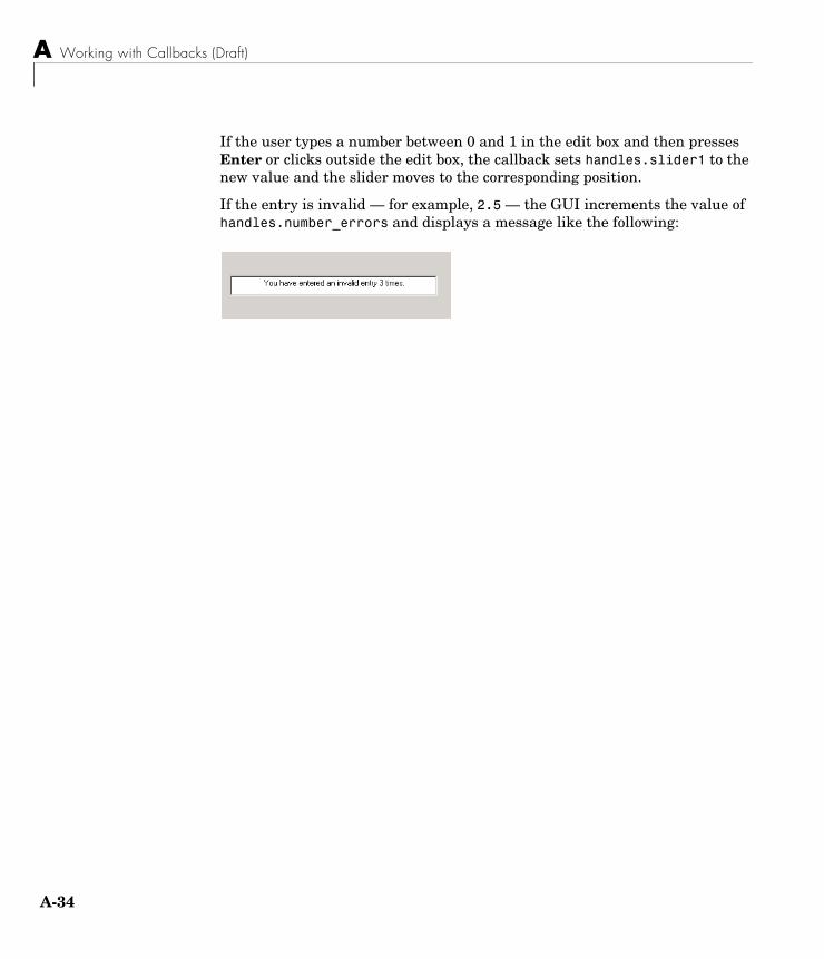
A Working with Callbacks (Draft)
A-34
If the user types a number between 0 and 1 in the edit box and then presses Enter or clicks outside the edit box, the callback sets handles.slider1 to the new value and the slider moves to the corresponding position.
If the entry is invalid — for example, 2.5 — the GUI increments the value of handles.number_errors and displays a message like the following:
Properties That Control Component Behavior
A-35
Properties That Control Component BehaviorVarious properties enable GUI callbacks to control component behavior. This section discusses those that are common to most components. Reference pages for the components discuss those that are particular to specific components.
In GUIDE, you can set these properties initially with the Property Inspector. You can set them programmatically when you create the component, or in your callbacks using the set and get functions.
If you create your GUI programmatically, you can set them when you create the component. In either case, you can modify them in your callbacks using the set and get functions.
For information about other properties including those that control the look and feel of the components, see the reference pages for each component.
The following topics describe the properties that control behavior:
• “General Information About the Component” on page A-35
• “Information About Component State” on page A-36
• “Properties that Affect Callback Execution” on page A-37
• “Properties that Affect Component Access” on page A-39
General Information About the ComponentThese are properties you need to navigate the GUI hierarchy and to identify or locate components.
ChildrenA vector of handles that describes the children of the component. You can use this property to reorder the children – effectively changing the tabbing and stacking order.
ParentThe handle of the parent component or figure. You can change a component’s parent by setting this property to the handle of the new parent.
A Working with Callbacks (Draft)
A-36
TagA string used to identify a component. In general, within a GUI, each component’s Tag is unique. GUIDE uses the Tag, in combination with the GUI name, to create callback names and some file names.
With the findobj function, you can locate an object with a given Tag. This saves you from defining object handles as global variables. For example, this function call returns the handles of all children (of the specified figures) that have the Tag value 'FormatTb'.
h = findobj(figurehandles,'Tag','FormatTb')
Information About Component StateAt any given time, a callback may need to assess or set its own state or that of another component in the GUI. The Enable, Visible, Selected, SelectedObject, and Value properties define the most commonly used states.
See the component reference pages for information about other properties that may be specific to a component.
EnableThe Enable property controls how components respond to left and right mouse button clicks. It also affects which callback routines execute. It applies to all uicontrols, menus, push tools, and toggle tools.
• on – The component is operational (the default). If a user clicks on a uicontrol for which Enable is set to on, ButtonDownFcn and WindowButtonDownFcn callbacks do not execute.
• inactive – The component is not operational, but looks the same as when Enable is on. This is not an option for some components.
If a user clicks on a uicontrol for which Enable is set to inactive, MATLAB first executes the WindownButtonDownFcn of the figure (if defined) and then the ButtonDownFcn of the uicontrol targeted by the mouse click.
• off – The component is not operational and its String or image (set by the CData property) is grayed out.
Actions differ somewhat for different components. See the specific component reference pages for more information.
Properties That Control Component Behavior
A-37
VisibleBy default, all components are visible. If you set the value of the Visible property to off, the component is not visible, but still exists and you can query and set its properties. If you make a container not visible, its children are also not visible, although their Visible properties are unchanged.
Setting Visible to off for components that are not displayed initially in the GUI, can result in faster startup time for the GUI.
SelectedYou can query this property to determine if a component is selected. When the Selected property is on, MATLAB displays selection handles if the SelectionHighlight property is also on.
You can, for example, define the ButtonDownFcn to set this property, allowing users to select the object with the mouse.
SelectedObjectUse this property to determine the currently selected radio button or toggle button in a button group. You can also use it to initialize selection of one of the radio buttons or toggle buttons. By default, SelectedObject is set to the first radio button or toggle button that is added to the button group. Set it to [] if you want no selection. Note that the SelectionChangeFcn callback does not execute when this property is set using the set command.
ValueA property of uicontrol components, this property represents the value of a specific component. For a slider, it is the number indicated on the slider bar. For a list box it is the index of the selected entry. See the Uicontrol Properties reference page for specific information for each style of uicontrol.
Properties that Affect Callback ExecutionBecause callbacks execute asynchronously in response to outside events, it is impossible to predict when a callback will run or what callback may already be running. Generally speaking, MATLAB queues the callbacks that are waiting to run until the one that is running can be interrupted or finishes execution. These two properties, BusyAction and Interruptible, let you influence this process. Except as noted, the value you assign each property applies to all callbacks of the given component.
A Working with Callbacks (Draft)
A-38
See “Interrupting Executing Callbacks” on page 4-37 for more information.
BusyActionThis property determines if a component’s callbacks should attempt to interrupt a previously executing callback.
• If the value is cancel, the event is discarded and the callback does not execute.
• If the value is queue, and the Interruptible property of the previously executing callback is on, the second callback is added to the event queue and executes in its turn after the first callback finishes execution or encounters a drawnow, figure, getframe, pause, or waitfor command.
Note If the interrupting callback is a DeleteFcn or CreateFcn callback, a figure’s CloseRequest callback, or a figure, panel, or button group’s ResizeFcn callback, it interrupts an executing callback regardless of the value of that component’s Interruptible property.
InterruptibleThis property determines whether a component’s callbacks can be interrupted. If a callback is executing and the user triggers an event (such as a mouse click) on an object for which a callback is defined, that callback attempts to interrupt the first callback. MATLAB processes the callbacks according to these factors:
• The Interruptible property of the object whose callback is executing
• Whether the executing callback contains drawnow, figure, getframe, pause, or waitfor statements
• The BusyAction property of the object whose callback is waiting to execute
If the Interruptible property of the object whose callback is executing is on (the default), the callback can be interrupted. Whenever the callback calls one of the drawnow, figure, getframe, pause, or waitfor functions, the function processes any events in the event queue, including the waiting callback, before performing its defined task.
If the Interruptible property of the object whose callback is executing is off, the callback cannot be interrupted (except by certain callbacks; see the note
Properties That Control Component Behavior
A-39
below). The BusyAction property of the object whose callback is waiting to execute determines what happens to its interrupting callback.
Note If the interrupting callback is a DeleteFcn or CreateFcn callback, a figure’s CloseRequest callback, or a figure, panel, or button group’s ResizeFcn callback, it interrupts an executing callback regardless of the value of that component’s Interruptible property.
Properties that Affect Component Access
HandleVisibilityThe HandleVisibility property controls access to a component’s handle. This property determines when a component’s handle is accessible in its parent’s list of children. When a handle is not accessible in a parent’s list of children, it is not returned by functions that obtain handles by searching the object hierarchy or querying handle properties with functions such as get, findobj, gca, gcf, gco, newplot, cla, clf, and close. Neither is the handle accessible in the parent figure’s CurrentObject property.
Handles that are hidden are still valid. If you know a component’s handle, you can set and get its properties, and pass it to any function that operates on handles.
• Handles are always accessible when HandleVisibility is on.
• Setting HandleVisibility to callback causes handles to be accessible from within callback routines or functions invoked by callback routines, but not from within functions invoked from the command line. This provides a means to protect GUIs from command-line users, while allowing callback routines to have complete access to the handles.
• Setting HandleVisibility to off makes handles inaccessible at all times. This may be necessary when a callback routine invokes a function that might potentially damage the GUI (such as evaluating a user-typed string), and so temporarily hides its own handles during the execution of that function.
You can set the root ShowHiddenHandles property to on to make all handles accessible, regardless of their HandleVisibility settings. This does not affect the values of the HandleVisibility properties.
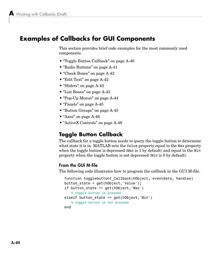
A Working with Callbacks (Draft)
A-40
Examples of Callbacks for GUI ComponentsThis section provides brief code examples for the most commonly used components.
• “Toggle Button Callback” on page A-40
• “Radio Buttons” on page A-41
• “Check Boxes” on page A-42
• “Edit Text” on page A-42
• “Sliders” on page A-43
• “List Boxes” on page A-43
• “Pop-Up Menus” on page A-44
• “Panels” on page A-45
• “Button Groups” on page A-45
• “Axes” on page A-46
• “ActiveX Controls” on page A-49
Toggle Button CallbackThe callback for a toggle button needs to query the toggle button to determine what state it is in. MATLAB sets the Value property equal to the Max property when the toggle button is depressed (Max is 1 by default) and equal to the Min property when the toggle button is not depressed (Min is 0 by default).
From the GUI M-fileThe following code illustrates how to program the callback in the GUI M-file.
function togglebutton1_Callback(hObject, eventdata, handles)button_state = get(hObject,'Value');if button_state == get(hObject,'Max')
% toggle button is pressed
elseif button_state == get(hObject,'Min')% toggle button is not pressed
end
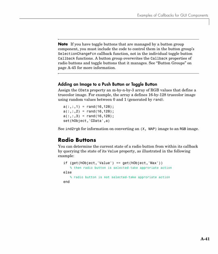
Examples of Callbacks for GUI Components
A-41
Note If you have toggle buttons that are managed by a button group component, you must include the code to control them in the button group’s SelectionChangeFcn callback function, not in the individual toggle button Callback functions. A button group overwrites the Callback properties of radio buttons and toggle buttons that it manages. See “Button Groups” on page A-45 for more information.
Adding an Image to a Push Button or Toggle ButtonAssign the CData property an m-by-n-by-3 array of RGB values that define a truecolor image. For example, the array a defines 16-by-128 truecolor image using random values between 0 and 1 (generated by rand).
a(:,:,1) = rand(16,128);a(:,:,2) = rand(16,128);a(:,:,3) = rand(16,128);set(hObject,'CData',a)
See ind2rgb for information on converting an (X, MAP) image to an RGB image.
Radio ButtonsYou can determine the current state of a radio button from within its callback by querying the state of its Value property, as illustrated in the following example:
if (get(hObject,'Value') == get(hObject,'Max'))% then radio button is selected-take approriate action
else% radio button is not selected-take approriate action
end
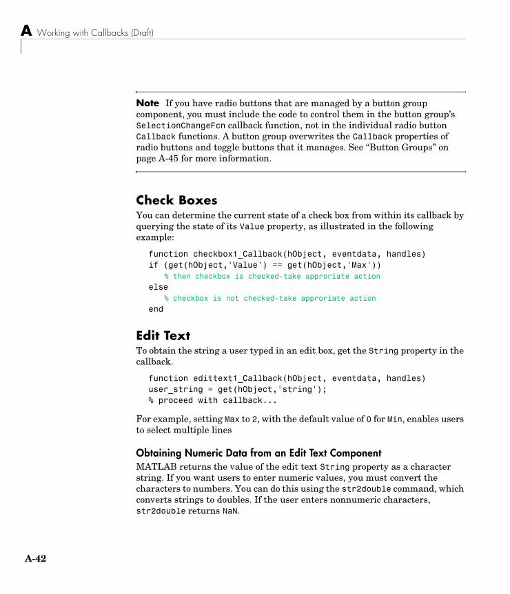
A Working with Callbacks (Draft)
A-42
Note If you have radio buttons that are managed by a button group component, you must include the code to control them in the button group’s SelectionChangeFcn callback function, not in the individual radio button Callback functions. A button group overwrites the Callback properties of radio buttons and toggle buttons that it manages. See “Button Groups” on page A-45 for more information.
Check Boxes You can determine the current state of a check box from within its callback by querying the state of its Value property, as illustrated in the following example:
function checkbox1_Callback(hObject, eventdata, handles)if (get(hObject,'Value') == get(hObject,'Max'))
% then checkbox is checked-take approriate action
else% checkbox is not checked-take approriate action
end
Edit Text To obtain the string a user typed in an edit box, get the String property in the callback.
function edittext1_Callback(hObject, eventdata, handles)user_string = get(hObject,'string');% proceed with callback...
For example, setting Max to 2, with the default value of 0 for Min, enables users to select multiple lines
Obtaining Numeric Data from an Edit Text ComponentMATLAB returns the value of the edit text String property as a character string. If you want users to enter numeric values, you must convert the characters to numbers. You can do this using the str2double command, which converts strings to doubles. If the user enters nonnumeric characters, str2double returns NaN.
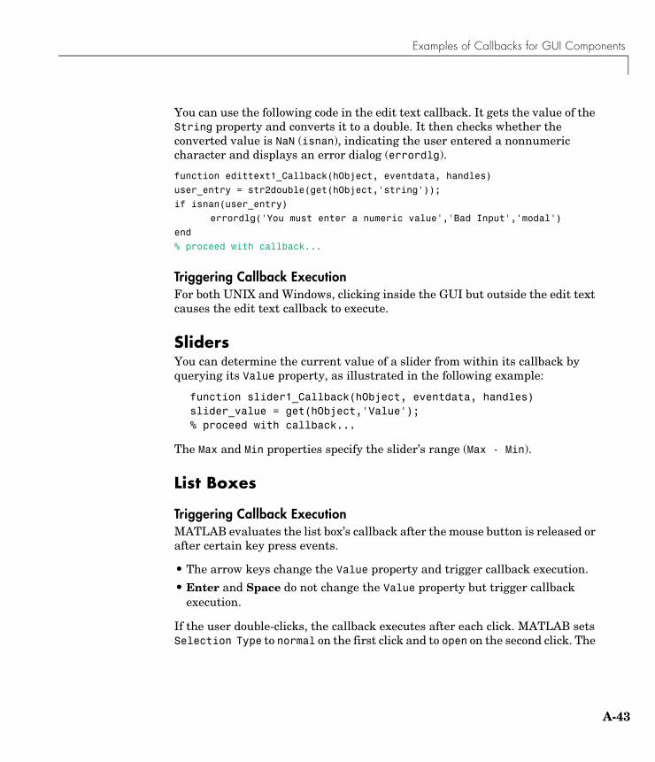
Examples of Callbacks for GUI Components
A-43
You can use the following code in the edit text callback. It gets the value of the String property and converts it to a double. It then checks whether the converted value is NaN (isnan), indicating the user entered a nonnumeric character and displays an error dialog (errordlg).
function edittext1_Callback(hObject, eventdata, handles)
user_entry = str2double(get(hObject,'string'));
if isnan(user_entry)
errordlg('You must enter a numeric value','Bad Input','modal')
end
% proceed with callback...
Triggering Callback ExecutionFor both UNIX and Windows, clicking inside the GUI but outside the edit text causes the edit text callback to execute.
SlidersYou can determine the current value of a slider from within its callback by querying its Value property, as illustrated in the following example:
function slider1_Callback(hObject, eventdata, handles)slider_value = get(hObject,'Value');% proceed with callback...
The Max and Min properties specify the slider’s range (Max - Min).
List Boxes
Triggering Callback ExecutionMATLAB evaluates the list box’s callback after the mouse button is released or after certain key press events.
• The arrow keys change the Value property and trigger callback execution.
• Enter and Space do not change the Value property but trigger callback execution.
If the user double-clicks, the callback executes after each click. MATLAB sets Selection Type to normal on the first click and to open on the second click. The
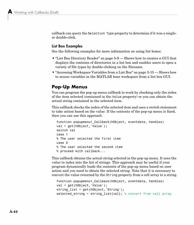
A Working with Callbacks (Draft)
A-44
callback can query the Selection Type property to determine if it was a single- or double-click.
List Box ExamplesSee the following examples for more information on using list boxes:
• “List Box Directory Reader” on page 5-9 — Shows how to creates a GUI that displays the contents of directories in a list box and enables users to open a variety of file types by double-clicking on the filename.
• “Accessing Workspace Variables from a List Box” on page 5-15 — Shows how to access variables in the MATLAB base workspace from a list box GUI.
Pop-Up Menus You can program the pop-up menu callback to work by checking only the index of the item selected (contained in the Value property) or you can obtain the actual string contained in the selected item.
This callback checks the index of the selected item and uses a switch statement to take action based on the value. If the contents of the pop-up menu is fixed, then you can use this approach.
function popupmenu1_Callback(hObject, eventdata, handles)val = get(hObject,'Value');switch valcase 1% The user selected the first itemcase 2% The user selected the second item% proceed with callback...
This callback obtains the actual string selected in the pop-up menu. It uses the value to index into the list of strings. This approach may be useful if your program dynamically loads the contents of the pop-up menu based on user action and you need to obtain the selected string. Note that it is necessary to convert the value returned by the String property from a cell array to a string.
function popupmenu1_Callback(hObject, eventdata, handles)val = get(hObject,'Value');string_list = get(hObject,'String');selected_string = string_list{val}; % convert from cell array
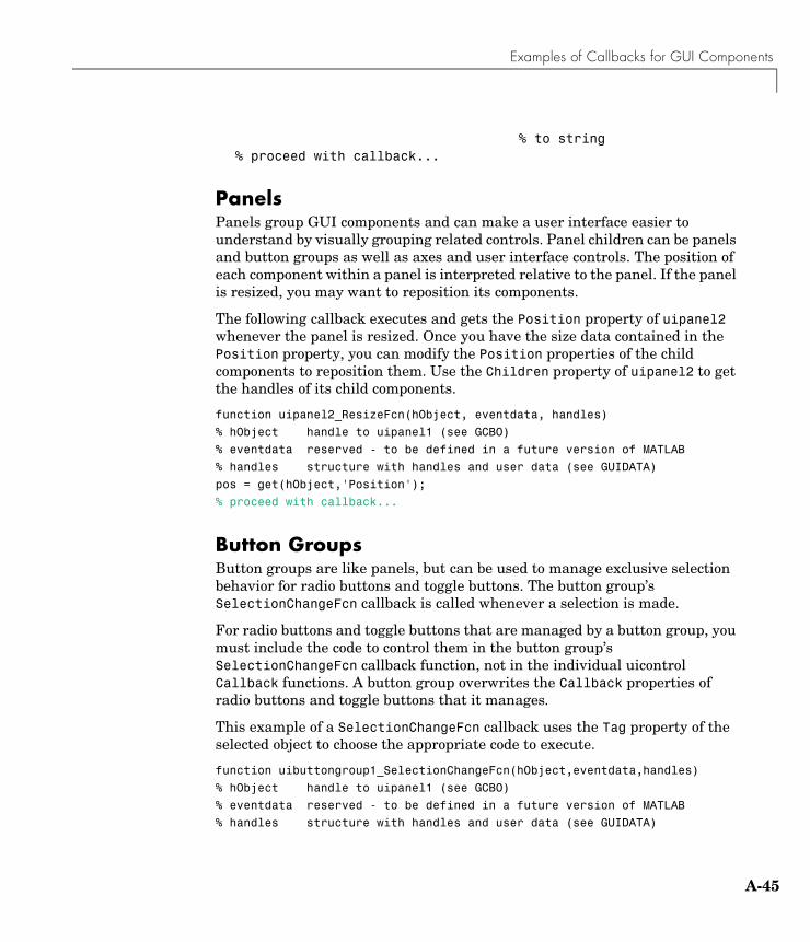
Examples of Callbacks for GUI Components
A-45
% to string% proceed with callback...
PanelsPanels group GUI components and can make a user interface easier to understand by visually grouping related controls. Panel children can be panels and button groups as well as axes and user interface controls. The position of each component within a panel is interpreted relative to the panel. If the panel is resized, you may want to reposition its components.
The following callback executes and gets the Position property of uipanel2 whenever the panel is resized. Once you have the size data contained in the Position property, you can modify the Position properties of the child components to reposition them. Use the Children property of uipanel2 to get the handles of its child components.
function uipanel2_ResizeFcn(hObject, eventdata, handles)
% hObject handle to uipanel1 (see GCBO)
% eventdata reserved - to be defined in a future version of MATLAB
% handles structure with handles and user data (see GUIDATA)
pos = get(hObject,'Position');
% proceed with callback...
Button GroupsButton groups are like panels, but can be used to manage exclusive selection behavior for radio buttons and toggle buttons. The button group’s SelectionChangeFcn callback is called whenever a selection is made.
For radio buttons and toggle buttons that are managed by a button group, you must include the code to control them in the button group’s SelectionChangeFcn callback function, not in the individual uicontrol Callback functions. A button group overwrites the Callback properties of radio buttons and toggle buttons that it manages.
This example of a SelectionChangeFcn callback uses the Tag property of the selected object to choose the appropriate code to execute.
function uibuttongroup1_SelectionChangeFcn(hObject,eventdata,handles)
% hObject handle to uipanel1 (see GCBO)
% eventdata reserved - to be defined in a future version of MATLAB
% handles structure with handles and user data (see GUIDATA)
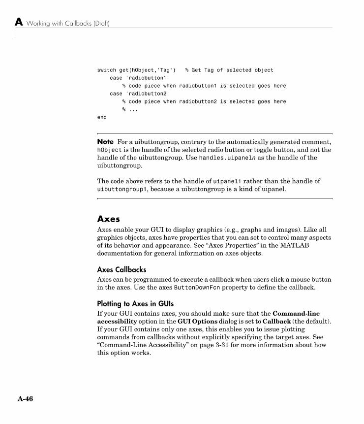
A Working with Callbacks (Draft)
A-46
switch get(hObject,'Tag') % Get Tag of selected object
case 'radiobutton1'
% code piece when radiobutton1 is selected goes here
case 'radiobutton2'
% code piece when radiobutton2 is selected goes here
% ...
end
Note For a uibuttongroup, contrary to the automatically generated comment, hObject is the handle of the selected radio button or toggle button, and not the handle of the uibuttongroup. Use handles.uipaneln as the handle of the uibuttongroup.
The code above refers to the handle of uipanel1 rather than the handle of uibuttongroup1, because a uibuttongroup is a kind of uipanel.
AxesAxes enable your GUI to display graphics (e.g., graphs and images). Like all graphics objects, axes have properties that you can set to control many aspects of its behavior and appearance. See “Axes Properties” in the MATLAB documentation for general information on axes objects.
Axes CallbacksAxes can be programmed to execute a callback when users click a mouse button in the axes. Use the axes ButtonDownFcn property to define the callback.
Plotting to Axes in GUIsIf your GUI contains axes, you should make sure that the Command-line accessibility option in the GUI Options dialog is set to Callback (the default). If your GUI contains only one axes, this enables you to issue plotting commands from callbacks without explicitly specifying the target axes. See “Command-Line Accessibility” on page 3-31 for more information about how this option works.
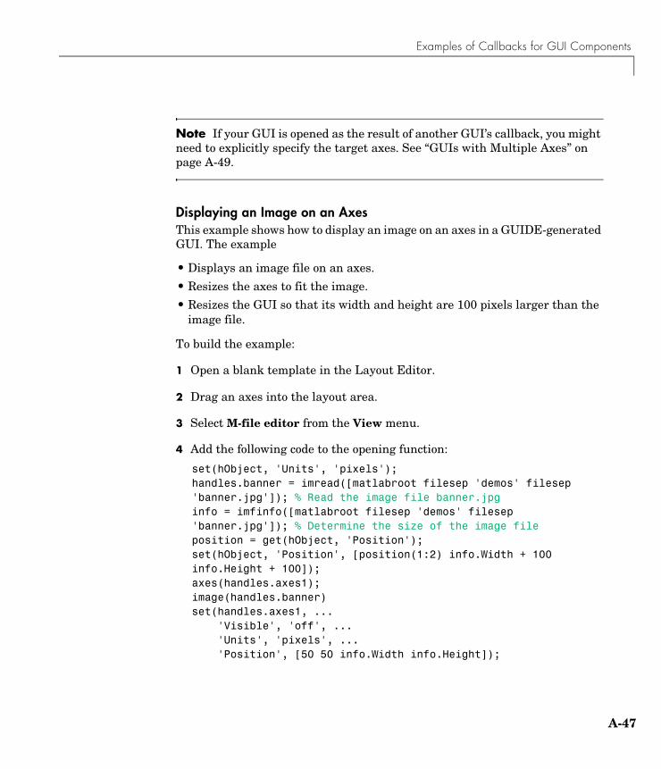
Examples of Callbacks for GUI Components
A-47
Note If your GUI is opened as the result of another GUI’s callback, you might need to explicitly specify the target axes. See “GUIs with Multiple Axes” on page A-49.
Displaying an Image on an AxesThis example shows how to display an image on an axes in a GUIDE-generated GUI. The example
• Displays an image file on an axes.
• Resizes the axes to fit the image.
• Resizes the GUI so that its width and height are 100 pixels larger than the image file.
To build the example:
1 Open a blank template in the Layout Editor.
2 Drag an axes into the layout area.
3 Select M-file editor from the View menu.
4 Add the following code to the opening function:
set(hObject, 'Units', 'pixels');handles.banner = imread([matlabroot filesep 'demos' filesep 'banner.jpg']); % Read the image file banner.jpginfo = imfinfo([matlabroot filesep 'demos' filesep 'banner.jpg']); % Determine the size of the image fileposition = get(hObject, 'Position');set(hObject, 'Position', [position(1:2) info.Width + 100 info.Height + 100]);axes(handles.axes1);image(handles.banner)set(handles.axes1, ... 'Visible', 'off', ... 'Units', 'pixels', ... 'Position', [50 50 info.Width info.Height]);
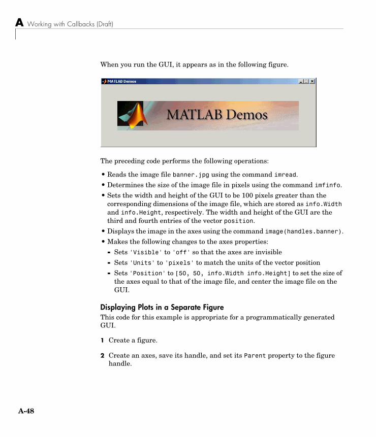
A Working with Callbacks (Draft)
A-48
When you run the GUI, it appears as in the following figure.
The preceding code performs the following operations:
• Reads the image file banner.jpg using the command imread.
• Determines the size of the image file in pixels using the command imfinfo.
• Sets the width and height of the GUI to be 100 pixels greater than the corresponding dimensions of the image file, which are stored as info.Width and info.Height, respectively. The width and height of the GUI are the third and fourth entries of the vector position.
• Displays the image in the axes using the command image(handles.banner).
• Makes the following changes to the axes properties:
- Sets 'Visible' to 'off' so that the axes are invisible
- Sets 'Units' to 'pixels' to match the units of the vector position
- Sets 'Position' to [50, 50, info.Width info.Height] to set the size of the axes equal to that of the image file, and center the image file on the GUI.
Displaying Plots in a Separate FigureThis code for this example is appropriate for a programmatically generated GUI.
1 Create a figure.
2 Create an axes, save its handle, and set its Parent property to the figure handle.
Examples of Callbacks for GUI Components
A-49
3 Create the plot, save its handles, and set the plot Parent property to the handle of the axes.
Note To prevent a figure from becoming the target of plotting commands issued at the command line or by other GUIs, you can set the HandleVisibility and IntegerHandle properties to off. However, this means the figure is also hidden from plotting commands issued by your GUI. To issue plotting commands from your GUI,
The following code illustrates these steps:
fHandle = figure('HandleVisibility','off','IntegerHandle','off',... 'Visible','off');aHandle = axes('Parent',fHandle);pHandles = plot(PlotData,'Parent',aHandle);set(fHandle,'Visible','on')
Note that not all plotting commands accept property name/property value specifications as arguments. Consult the reference page for the specific command to see what arguments you can specify.
GUIs with Multiple AxesIf a GUI has multiple axes, you should explicitly specify which axes you want to target when you issue plotting commands. You can do this using the axes command and the handles structure. For example,
axes(handles.axes1)
makes the axes whose Tag property is axes1 the current axes, and therefore the target for plotting commands. You can switch the current axes whenever you want to target a different axes. See “GUI with Multiple Axes” on page 5-2 for an example that uses two axes.
ActiveX ControlsYou can insert an ActiveX control into your GUI if you are running MATLAB on Microsoft Windows. When you drag an ActiveX component from the component palette into the layout area, GUIDE displays a dialog in which you
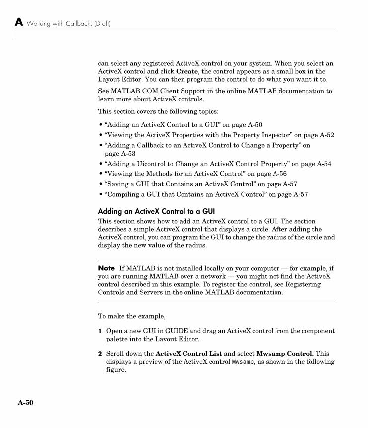
A Working with Callbacks (Draft)
A-50
can select any registered ActiveX control on your system. When you select an ActiveX control and click Create, the control appears as a small box in the Layout Editor. You can then program the control to do what you want it to.
See MATLAB COM Client Support in the online MATLAB documentation to learn more about ActiveX controls.
This section covers the following topics:
• “Adding an ActiveX Control to a GUI” on page A-50
• “Viewing the ActiveX Properties with the Property Inspector” on page A-52
• “Adding a Callback to an ActiveX Control to Change a Property” on page A-53
• “Adding a Uicontrol to Change an ActiveX Control Property” on page A-54
• “Viewing the Methods for an ActiveX Control” on page A-56
• “Saving a GUI that Contains an ActiveX Control” on page A-57
• “Compiling a GUI that Contains an ActiveX Control” on page A-57
Adding an ActiveX Control to a GUIThis section shows how to add an ActiveX control to a GUI. The section describes a simple ActiveX control that displays a circle. After adding the ActiveX control, you can program the GUI to change the radius of the circle and display the new value of the radius.
Note If MATLAB is not installed locally on your computer — for example, if you are running MATLAB over a network — you might not find the ActiveX control described in this example. To register the control, see Registering Controls and Servers in the online MATLAB documentation.
To make the example,
1 Open a new GUI in GUIDE and drag an ActiveX control from the component palette into the Layout Editor.
2 Scroll down the ActiveX Control List and select Mwsamp Control. This displays a preview of the ActiveX control Mwsamp, as shown in the following figure.
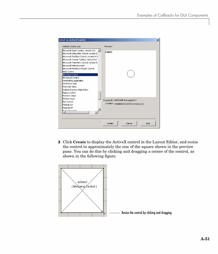
Examples of Callbacks for GUI Components
A-51
3 Click Create to display the ActiveX control in the Layout Editor, and resize the control to approximately the size of the square shown in the preview pane. You can do this by clicking and dragging a corner of the control, as shown in the following figure.
Resize the control by clicking and dragging
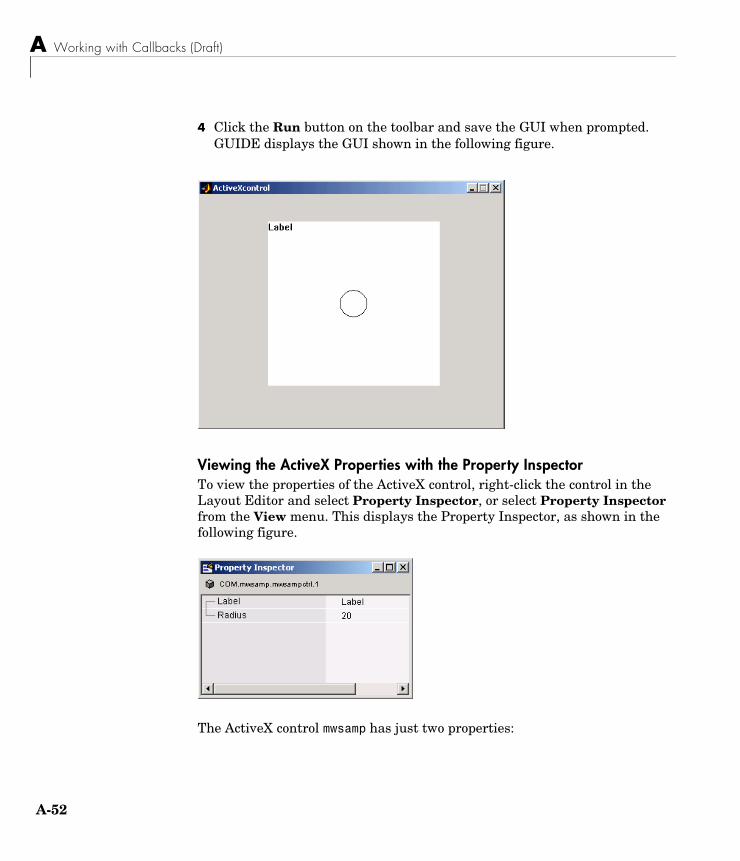
A Working with Callbacks (Draft)
A-52
4 Click the Run button on the toolbar and save the GUI when prompted. GUIDE displays the GUI shown in the following figure.
Viewing the ActiveX Properties with the Property InspectorTo view the properties of the ActiveX control, right-click the control in the Layout Editor and select Property Inspector, or select Property Inspector from the View menu. This displays the Property Inspector, as shown in the following figure.
The ActiveX control mwsamp has just two properties:
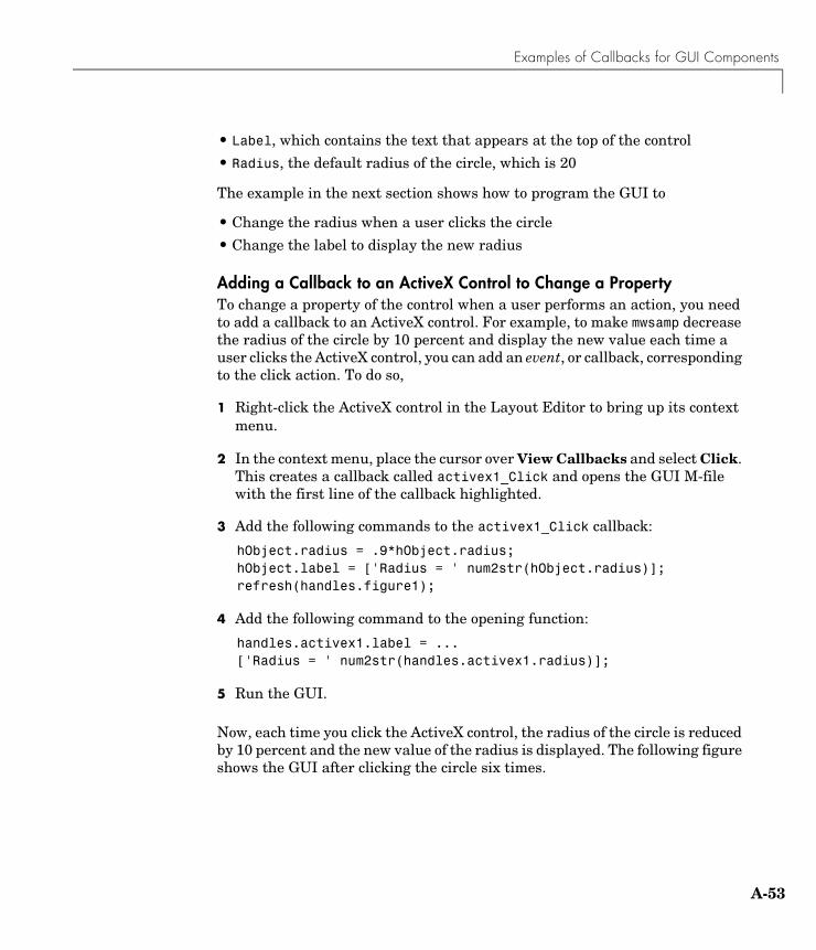
Examples of Callbacks for GUI Components
A-53
• Label, which contains the text that appears at the top of the control
• Radius, the default radius of the circle, which is 20
The example in the next section shows how to program the GUI to
• Change the radius when a user clicks the circle
• Change the label to display the new radius
Adding a Callback to an ActiveX Control to Change a Property To change a property of the control when a user performs an action, you need to add a callback to an ActiveX control. For example, to make mwsamp decrease the radius of the circle by 10 percent and display the new value each time a user clicks the ActiveX control, you can add an event, or callback, corresponding to the click action. To do so,
1 Right-click the ActiveX control in the Layout Editor to bring up its context menu.
2 In the context menu, place the cursor over View Callbacks and select Click. This creates a callback called activex1_Click and opens the GUI M-file with the first line of the callback highlighted.
3 Add the following commands to the activex1_Click callback:
hObject.radius = .9*hObject.radius;hObject.label = ['Radius = ' num2str(hObject.radius)];refresh(handles.figure1);
4 Add the following command to the opening function:
handles.activex1.label = ...['Radius = ' num2str(handles.activex1.radius)];
5 Run the GUI.
Now, each time you click the ActiveX control, the radius of the circle is reduced by 10 percent and the new value of the radius is displayed. The following figure shows the GUI after clicking the circle six times.
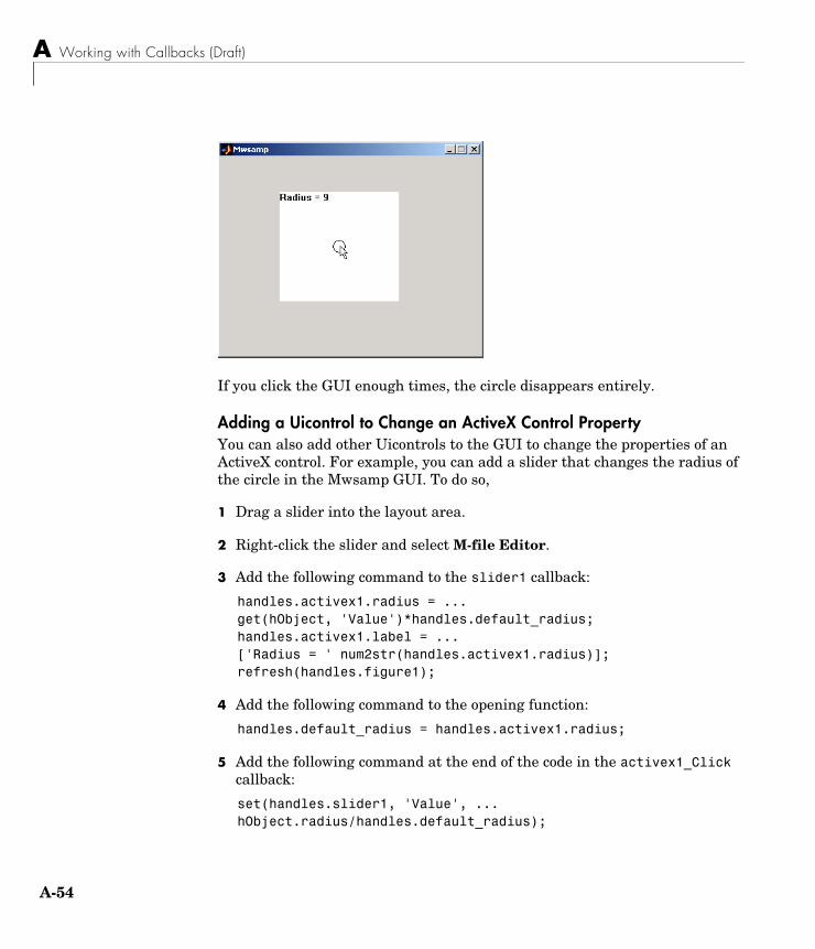
A Working with Callbacks (Draft)
A-54
If you click the GUI enough times, the circle disappears entirely.
Adding a Uicontrol to Change an ActiveX Control PropertyYou can also add other Uicontrols to the GUI to change the properties of an ActiveX control. For example, you can add a slider that changes the radius of the circle in the Mwsamp GUI. To do so,
1 Drag a slider into the layout area.
2 Right-click the slider and select M-file Editor.
3 Add the following command to the slider1 callback:
handles.activex1.radius = ...get(hObject, 'Value')*handles.default_radius;handles.activex1.label = ...['Radius = ' num2str(handles.activex1.radius)];refresh(handles.figure1);
4 Add the following command to the opening function:
handles.default_radius = handles.activex1.radius;
5 Add the following command at the end of the code in the activex1_Click callback:
set(handles.slider1, 'Value', ... hObject.radius/handles.default_radius);
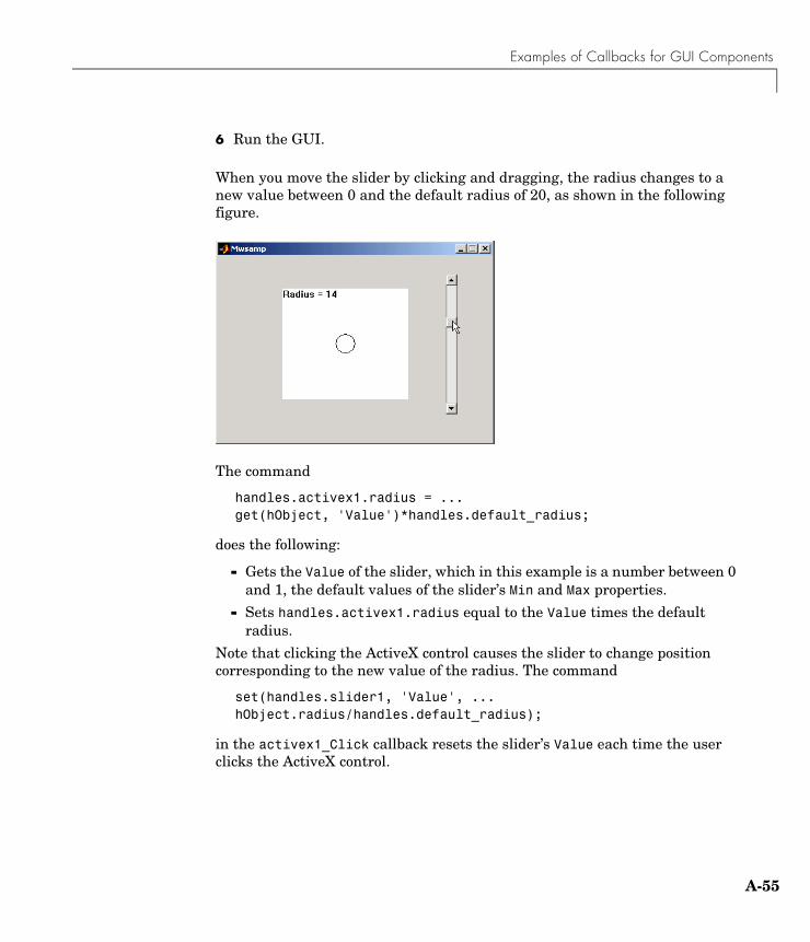
Examples of Callbacks for GUI Components
A-55
6 Run the GUI.
When you move the slider by clicking and dragging, the radius changes to a new value between 0 and the default radius of 20, as shown in the following figure.
The command
handles.activex1.radius = ...get(hObject, 'Value')*handles.default_radius;
does the following:
- Gets the Value of the slider, which in this example is a number between 0 and 1, the default values of the slider’s Min and Max properties.
- Sets handles.activex1.radius equal to the Value times the default radius.
Note that clicking the ActiveX control causes the slider to change position corresponding to the new value of the radius. The command
set(handles.slider1, 'Value', ... hObject.radius/handles.default_radius);
in the activex1_Click callback resets the slider’s Value each time the user clicks the ActiveX control.
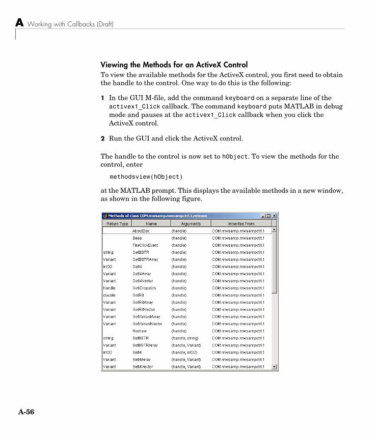
A Working with Callbacks (Draft)
A-56
Viewing the Methods for an ActiveX ControlTo view the available methods for the ActiveX control, you first need to obtain the handle to the control. One way to do this is the following:
1 In the GUI M-file, add the command keyboard on a separate line of the activex1_Click callback. The command keyboard puts MATLAB in debug mode and pauses at the activex1_Click callback when you click the ActiveX control.
2 Run the GUI and click the ActiveX control.
The handle to the control is now set to hObject. To view the methods for the control, enter
methodsview(hObject)
at the MATLAB prompt. This displays the available methods in a new window, as shown in the following figure.
Examples of Callbacks for GUI Components
A-57
Alternatively, you can enter
methods(hObject)
which displays the available methods in the Command Window.
For more information about methods for ActiveX controls, see Invoking Methods in the online MATLAB documentation. See the reference pages for methodsview and methods for more information about these functions.
Saving a GUI that Contains an ActiveX Control When you save a GUI that contains ActiveX controls, GUIDE creates a file in the current directory for each such control. The filename consists of the name of the GUI followed by an underscore (_) and activexn, where n is a sequence number. For example, if the GUI is named mygui then the filename would be mygui_activex1. The filename does not have an extension.
Compiling a GUI that Contains an ActiveX ControlIf you use the MATLAB Compiler mcc command to compile a GUI that contains an ActiveX control, you must use the -a flag to add the ActiveX file, which GUIDE saves in the current directory, to the CTF archive. Your command should be similar to this
mcc -m mygui -a mygui_activex1
where mygui_activex1 is the name of the ActiveX file. See the MATLAB Compiler documentation for more information. If you have more than one such file, use a separate -a flag for each file. You must have installed the MATLAB Compiler to compile a GUI.

A Working with Callbacks (Draft)
A-58
Index-1
Index
Aactivate figure 3-19ActiveX controls 4-17, A-49aligning GUI components 3-38Alignment Tool, for GUIs 3-38application data 4-31application M-file 4-2application options 3-29axes
multiple in GUI 5-2axes, plotting when hidden 5-27
Bbutton groups 3-13
adding components 3-14
Ccallback
arguments 3-35callback syntax 3-34callbacks
adding to GUI M-file in GUIDE 3-56interrupting 4-37types 4-35
check boxes 4-10, A-42color of GUI background 3-36command-line accessibility of GUIs 3-31context menus
associating with an object 3-72creating with GUIDE 3-69menu items 3-70parent menu 3-69
Ddisplaying an image 4-15, A-47
Eedit text 3-48, 4-10, A-42editable text 4-10, A-42event queue 4-37
GGUI
help button 5-29resize function 5-43resizing 3-30with multiple axes 5-2
GUI componentscopying 3-18cutting and clearing 3-18moving 3-17pasting and duplicating 3-18selecting 3-17
GUI layoutcopying components 3-18cutting and clearing components 3-18moving components 3-17pasting and duplicating components 3-18selecting components 3-17
GUI M-filesadding callbacks in GUIDE 3-56
GUI programming 4-1GUIDE
application examples 5-1application M-file 4-2application options 3-29command-line accessibility of GUIs 3-31
Index
Index-2
GUIDE (continued)creating menus 3-61demonstration 2-3editing version 5 GUIs 1-12generated M-file 3-33grids and rulers 3-40GUI background color 3-36handles structure and global data 4-27introduction 1-2layout tools 3-1programming the GUI 4-1Property Inspector 3-44resizing GUIs 3-30setting properties 3-44
Hhandles structure 4-27help button for GUIs 5-29hidden figure, accessing 5-27
LLayout Editor 3-9
controls 1-4Layout Tools, GUI 3-1list box
example 5-9list boxes 3-49, 4-11, A-43
MMenu Editor 3-61menus
callbacks 3-67context menus 3-69creating with GUIDE 3-61
drop-down menus 3-62menu bar menus 3-62menu items 3-63, 3-70parent of context menu 3-69pop-up 4-12, A-44shortcut menus 3-69specifying properties 3-62
M-filegenerated by GUIDE 3-33
modal GUIs 4-40
OObject Browser 3-60opening .fig files 5-14
Ppanels 3-12
adding components 3-14GUI layout example 2-2
pop-up menus 3-51, 4-12, A-44Property Inspector 3-44
Rradio buttons 3-48, 4-9, A-41resize function for GUI 5-43resizing GUIs 3-30
Ssharing data in GUIs 4-27single instance 3-36slider 3-49sliders 3-12
Index
Index-3
Ttoggle buttons 4-8, A-40toolbar menus
creating with GUIDE 3-62

Index
Index-4