mathematical simulation and optimization of methanol dehydration and cyclohexane dehydrogenation in...
TRANSCRIPT
i n t e rn a t i o n a l j o u r n a l o f h y d r o g e n en e r g y 3 6 ( 2 0 1 1 ) 1 4 4 1 6e1 4 4 2 7
Avai lab le at www.sc iencedi rect .com
journa l homepage : www.e lsev ie r . com/ loca te /he
Mathematical simulation and optimization of methanoldehydration and cyclohexane dehydrogenation in a thermallycoupled dual-membrane reactor
M. Farsi, A. Jahanmiri*
Department of Chemical Engineering, School of Chemical and Petroleum Engineering, Shiraz University, Shiraz, Iran
a r t i c l e i n f o
Article history:
Received 7 March 2011
Received in revised form
3 August 2011
Accepted 7 August 2011
Available online 15 September 2011
Keywords:
DME
Benzene
Thermally coupled reactor
Dual-membrane reactor
Differential evolution
* Corresponding author. Tel.: þ98 711 230307E-mail address: [email protected] (A
0360-3199/$ e see front matter Copyright ªdoi:10.1016/j.ijhydene.2011.08.019
a b s t r a c t
Thermally coupling of endothermic and exothermic reactions in a membrane reactor
improves thermal efficiency and production rate in the processes, reduces the size of
reactors and decreases purification cost. This paper focuses on modeling and optimization
of a thermally coupled dual-membrane reactor for simultaneous production of hydrogen,
dimethyl ether (DME) and benzene. A steady state heterogeneous mathematical model is
developed to predict the performance of this novel configuration. The catalytic methanol
dehydration reaction takes place in the exothermic side that supplies the necessary heat
for the catalytic dehydrogenation of cyclohexane to benzene in the endothermic side.
Selective permeation of hydrogen and water vapor through the Pd/Ag and composite
membranes are achieved by co-current flow of sweep gas through the membrane wall. The
differential evolution method is applied to optimize the thermally coupled dual-membrane
reactor considering the summation of DME and benzene mole fractions from reaction sides
and hydrogen mole fraction in the permeation side as the main objectives. The optimi-
zation results are compared with corresponding predictions for an industrial methanol
dehydration adiabatic reactor operated at the same feed conditions. Methanol conversion
enhances about 5.5% in the optimized thermally coupled dual-membrane reactor relative
to the conventional DME reactor. The results suggest that coupling of these reactions in the
proposed configuration could be feasible and beneficial.
Copyright ª 2011, Hydrogen Energy Publications, LLC. Published by Elsevier Ltd. All rights
reserved.
1. Introduction hydrogen, and the high energy density storage of liquid fuel. It
Significant commercial and regulatory developments world-
wide are driving large increases in dimethyl ether (DME)
production capacity, and demonstrating its remarkable
potential as an ultra clean, renewable, low-carbon fuel. It can
be stored in liquid phase at moderate pressure, and delivered
as a gas phase fuel in a pumpless operation. Therefore, DME
has the advantages of easy fuel delivery of pressurized
1; fax: þ98 711 6287294.. Jahanmiri).2011, Hydrogen Energy P
is a clean fuel with high cetane number, excellent combustion
characteristics and extremely low toxicity that does not
produce any particulate matter at burning. It can be produced
from various raw materials such as petroleum residues, coal
bed methane, and biomass as well as natural gas and coal [1].
DME is useful for a variety of applications such as power
generation, diesel engines, fuel cell and domestic household
[2]. Due to these properties, it is an attractive topic in academic
ublications, LLC. Published by Elsevier Ltd. All rights reserved.
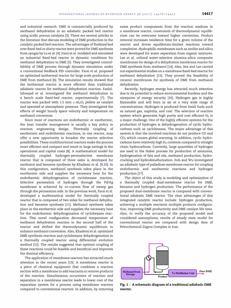
Pure DME
Product
Methanol fromStorage To Distillation Unit
Fig. 1 e A schematic diagram of a traditional adiabatic DME
reactor.
i n t e r n a t i o n a l j o u r n a l o f h y d r o g e n en e r g y 3 6 ( 2 0 1 1 ) 1 4 4 1 6e1 4 4 2 7 14417
and industrial research. DME is commercially produced by
methanol dehydration in an adiabatic packed bed reactor
using acidic porous catalysts [3]. There are several articles in
the literature that discuss modeling of DME production in the
catalytic packed bed reactors. The advantages of fluidized bed
over fixed-bed or slurry reactorwere proved for DME synthesis
from syngas by Lu et al. [4]. Farsi et al. modeled and simulated
an industrial fixed-bed reactor in dynamic conditions for
methanol dehydration to DME [5]. They investigated control-
lability of DME process through dynamic simulation under
a conventional feedback PID controller. Farsi et al. proposed
an optimized isothermal reactor for large scale production of
DME from methanol [6]. The simulation results showed that
the isothermal reactor is more efficient than traditional
adiabatic reactor for methanol dehydration reaction. Fazlol-
lahnejad et al. investigated the methanol dehydration in
a bench scale fixed-bed reactor, experimentally [7]. The
reactor was packed with 1.5 mm g-Al2O3 pellets as catalyst
and operated at atmospheric pressure. They investigated the
effects of weight hourly space velocity and temperature on
methanol conversion.
Since most of reactions are endothermic or exothermic,
the heat transfer management is usually a key policy in
reaction engineering design. Thermally coupling of
exothermic and endothermic reactions, in one reactor, may
offer a new opportunity to broaden the reactor selection
possibilities. Thesemultifunctional reactorsmake the process
more efficient and compact and result in large savings in the
operational and capital costs [8]. A mathematical model for
thermally coupled hydrogen-permselective membrane
reactor that is composed of three sides is developed for
methanol and benzene synthesis by Khademi et al. [9,10]. In
this configuration, methanol synthesis takes place in the
exothermic side and supplies the necessary heat for the
endothermic dehydrogenation of cyclohexane reaction.
Selective permeation of hydrogen through the Pd/Ag
membrane is achieved by co-current flow of sweep gas
through the permeation side. In the previous work, Farsi et al.
developed a mathematical model for thermally coupled
reactor that is composed of two sides for methanol dehydra-
tion and benzene synthesis [11]. Methanol synthesis takes
place in the exothermic side and supplies the necessary heat
for the endothermic dehydrogenation of cyclohexane reac-
tion. This novel configuration decreased temperature of
methanol dehydration reaction in the second half of the
reactor and shifted the thermodynamic equilibrium to
enhancemethanol conversion. Also, Khademi et al. optimized
DME synthesis reaction and cyclohexane dehydrogenation in
a thermally coupled reactor using differential evolution
method [12]. The results suggested that optimal coupling of
these reactions could be feasible and beneficial and improves
the thermal efficiency.
The application of membrane reactors has attracted much
attention in the recent years [13]. A membrane reactor is
a piece of chemical equipment that combines a reaction
sectionwith amembrane to add reactants or remove products
of the reaction. Simultaneous occurrence of reaction and
separation in a membrane reactor leads to lower cost of the
separation system for a process using membrane reactors
compared to conventional reactors. In addition, by removing
some product components from the reaction medium in
a membrane reactor, constraints of thermodynamic equilib-
rium can be overcome toward higher conversion. Product
removal increases residence time for a given volume of the
reactor and drives equilibrium-limited reactions toward
completion. Hydrophilic membranes such as zeolite and silica
were developed for water separation from organic mixtures.
Lee et al. utilized water-selective alumina-silica composite
membranes for design of a dehydrationmembrane reactor for
DME synthesis from methanol [14]. Also, Sea and Lee carried
out experimental studies on amembrane fixed-bed reactor for
methanol dehydration [15]. They proved the feasibility of
ceramic membranes for synthesis of DME from methanol
dehydration.
Recently, hydrogen energy has attracted much attention
due to its potential to reduce environmental burdens and the
viewpoint of energy security [16]. Hydrogen gas is highly
flammable and will burn in air at a very wide range of
concentrations. Hydrogen is produced from fossil fuels such
as natural gas, naphtha, and coal. The selection of reaction
system which generates high purity and cost efficient H2 is
a major challenge. One of the highly efficient systems for the
production of hydrogen is dehydrogenation of cyclic hydro-
carbons such as cyclohexane. The major advantage of this
system is that the involved reactions do not produce CO and
CO2 which causes global warming. In addition, cyclic hydro-
carbons have relatively high H2 contents compared to straight
chain hydrocarbons. Currently, large quantities of hydrogen
are used in the Haber process for production of ammonia,
hydrogenation of fats and oils, methanol production, hydro-
cracking and hydrodesulfurization. Itoh and Wu investigated
an adiabatic type of palladiummembrane reactor for coupling
endothermic and exothermic reactions and hydrogen
production [17].
The object of this study is modeling and optimization of
a thermally coupled dual-membrane reactor for DME,
benzene and hydrogen production. The performance of the
proposed dual-membrane reactor is compared with conven-
tional adiabatic DME reactor. The clear advantages of this
integrated catalytic reactor include: hydrogen production,
achieving a multiple reactants multiple products configura-
tion, improving DME productivity and DME catalyst life time.
Also, to verify the accuracy of the proposed model and
considered assumptions, results of steady state model for
conventional reactor are compared with design data of
Petrochemical Zagros Complex in Iran.
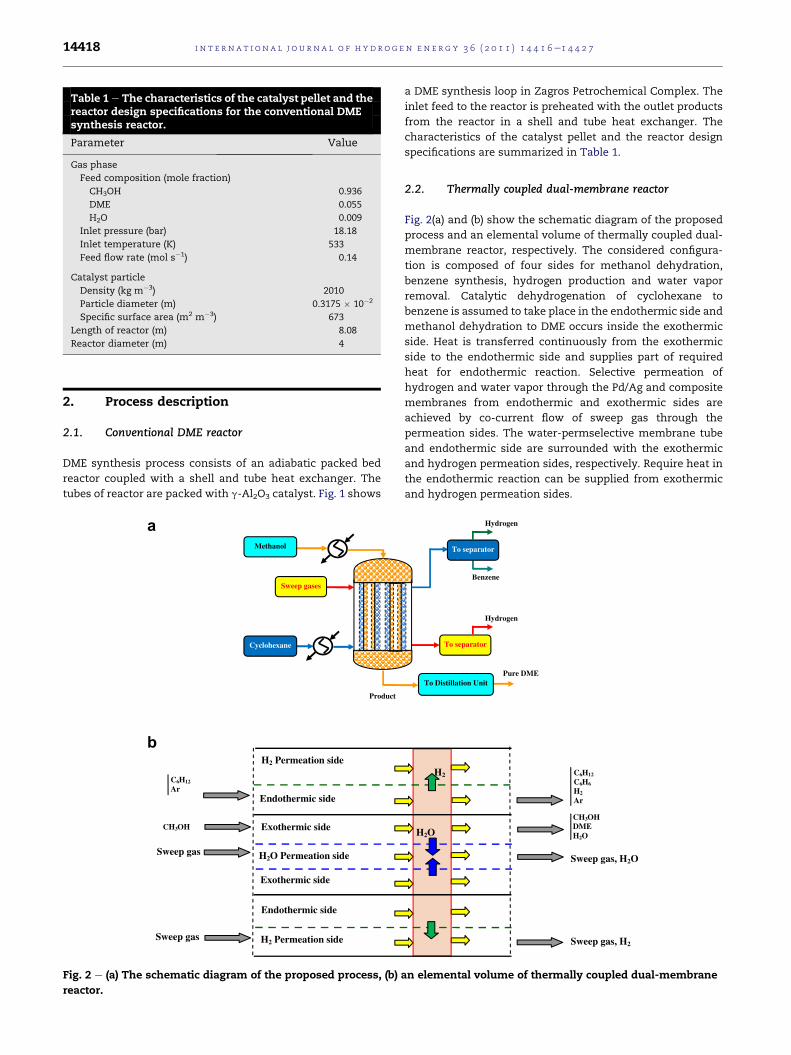
Table 1 e The characteristics of the catalyst pellet and thereactor design specifications for the conventional DMEsynthesis reactor.
Parameter Value
Gas phase
Feed composition (mole fraction)
CH3OH 0.936
DME 0.055
H2O 0.009
Inlet pressure (bar) 18.18
Inlet temperature (K) 533
Feed flow rate (mol s�1) 0.14
Catalyst particle
Density (kg m�3) 2010
Particle diameter (m) 0.3175 � 10�2
Specific surface area (m2 m�3) 673
Length of reactor (m) 8.08
Reactor diameter (m) 4
i n t e rn a t i o n a l j o u r n a l o f h y d r o g e n en e r g y 3 6 ( 2 0 1 1 ) 1 4 4 1 6e1 4 4 2 714418
2. Process description
2.1. Conventional DME reactor
DME synthesis process consists of an adiabatic packed bed
reactor coupled with a shell and tube heat exchanger. The
tubes of reactor are packed with g-Al2O3 catalyst. Fig. 1 shows
Product
Methanol
Cyclohexane
Sweep gases
Sweep gas
CH3OH
C6H12
Ar
Sweep gas H2O Permeation side
H2 Permeation side
H2 Permeation side
Endothermic side
Endothermic side
Exothermic side
Exothermic side
a
b
Fig. 2 e (a) The schematic diagram of the proposed process, (b)
reactor.
a DME synthesis loop in Zagros Petrochemical Complex. The
inlet feed to the reactor is preheated with the outlet products
from the reactor in a shell and tube heat exchanger. The
characteristics of the catalyst pellet and the reactor design
specifications are summarized in Table 1.
2.2. Thermally coupled dual-membrane reactor
Fig. 2(a) and (b) show the schematic diagram of the proposed
process and an elemental volume of thermally coupled dual-
membrane reactor, respectively. The considered configura-
tion is composed of four sides for methanol dehydration,
benzene synthesis, hydrogen production and water vapor
removal. Catalytic dehydrogenation of cyclohexane to
benzene is assumed to take place in the endothermic side and
methanol dehydration to DME occurs inside the exothermic
side. Heat is transferred continuously from the exothermic
side to the endothermic side and supplies part of required
heat for endothermic reaction. Selective permeation of
hydrogen and water vapor through the Pd/Ag and composite
membranes from endothermic and exothermic sides are
achieved by co-current flow of sweep gas through the
permeation sides. The water-permselective membrane tube
and endothermic side are surrounded with the exothermic
and hydrogen permeation sides, respectively. Require heat in
the endothermic reaction can be supplied from exothermic
and hydrogen permeation sides.
Pure DME
Benzene
Hydrogen
Hydrogen
To Distillation Unit
To separator
To separator
Sweep gas, H2
CH3OHDMEH2O
C6H12
C6H6
H2
Ar
Sweep gas, H2O
H2
H2O
an elemental volume of thermally coupled dual-membrane
i n t e r n a t i o n a l j o u r n a l o f h y d r o g e n en e r g y 3 6 ( 2 0 1 1 ) 1 4 4 1 6e1 4 4 2 7 14419
3. Reactions schemes and kinetics
3.1. DME synthesis reaction
The reaction of DME synthesis is mainly dehydration of
methanol that is an exothermic and equilibrium reaction.
Many researches are focused on DME synthesis reaction
[18e20]. The reaction rate equation for methanol dehydration
and rate parameters are used from Bercic and Levec [21].
Commercially, g-Al2O3 catalyst is used in the methanol
dehydration reaction.
2CH3OH4CH3OCH3 þH2O DH298 ¼ �23:4 kJ=mol (1)
3.2. Benzene synthesis reaction
The selected endothermic reaction is cyclohexane dehydroge-
nation to benzene. Cyclohexane dehydrogenation is an
attractive alternative for hydrogen production because it has
essentially without CO and CO2 emission. Jeong et al. studied
the catalytic dehydrogenation of cyclohexane experimentally
and observed that no by-product except benzene and hydrogen
is produced in this system [22]. The reaction scheme for the
dehydrogenation of cyclohexane to benzene is as follows:
C6H124C6H6 þ 3H2 DH298 ¼ þ206:2 kJ=mol (2)
The temperature of this reaction is in the range of 423e523 K
and the total pressure in the reactor is maintained at 101.3 kPa.
The reaction rate equation for cyclohexane dehydrogenation
and rate parameters are selected from Itoh [23]. The rate of
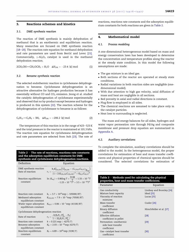
Table 2 e The rate of reactions, reactions rate constantsand the adsorption equilibrium constants for DMEsynthesis and cyclohexane dehydrogenation reactions.
Definition Equation
DME synthesis reaction
Rate of reaction r1 ¼k1K2
CH3OH
�C2CH3OH � ðCC2H6OCH2OÞ=Keq
�
ð1þ 2ðKCH3OHCCH3OHÞ:5 þ KH2OCH2OÞ4
Reaction equilibrium
constant
ln ðKeqÞ ¼ 0:86log Tþ 3138T
þ 1:33� 10�3T
�1:23� 10�5T2 þ 3:5� 10�10T3
Reaction rate constant k1 ¼ 3:7� 1010exp ð�105000=RTÞMethanol adsorption
equilibrium constant
KCH3OH ¼ 7:9� 10�4exp ð70500=RTÞ
Water vapor adsorption
equilibrium constant
KH2O ¼ 0:84� 10�1exp ð41100=RTÞ
Cyclohexane dehydrogenation reaction
Rate of reaction r2 ¼ �kðKPPC=P3H2� PBÞ
1þ ðKBKPPC=P3H2Þ
Reaction rate constant k ¼ 0:221 exp ð�4270=TÞBenzene adsorption
equilibrium constant
KB ¼ 2:03� 10�10exp ð6270=TÞ
Reaction equilibrium
constant
KP ¼ 4:89� 1035exp ð3190=TÞ
reactions, reactions rate constants and the adsorption equilib-
rium constants for both reactions are given in Table 2.
4. Mathematical model
4.1. Process modeling
A one-dimensional heterogeneous model based on mass and
energy conservation laws has been developed to determine
the concentration and temperature profiles along the reactor
at the steady state condition. In this model the following
assumptions are made:
� The gas mixture is an ideal gas.
� Both sections of the reactor are operated at steady state
conditions.
� Radial variations in both reaction sides are negligible (one-
dimensional model).
� With due attention to high gas velocity, axial diffusion of
mass and heat are negligible in all sections.
� Bed porosity in axial and radial directions is constant.
� Plug flow is employed in all sides.
� The chemical reactions are assumed to take place only in
the catalyst particles.
� Heat loss to surrounding is neglected.
The mass and energy balances for all sides, hydrogen and
water vapor permeation rate through Pd/Ag and composite
membrane and pressure drop equation are summarized in
Appendix A.
4.2. Auxiliary correlations
To complete the simulation, auxiliary correlations should be
added to the model. In the heterogeneous model, the proper
correlations for estimation of heat and mass transfer coeffi-
cients and physical properties of chemical species should be
considered. The selected correlations for estimation of
Table 3 e Methods used for calculating the physicalproperties, heat and mass transfer coefficients.
Parameter Equation
Gas conductivity Lindsay and Bromley [24]
Mixture heat capacity Ideal [25]
Viscosity of reaction
mixtures
Lucas [25]
Mass transfer
coefficient
Cusler [26]
Binary diffusion
coefficient
Hirschfelder et al. [27]
Effective diffusion
coefficient in pellet
[28]
Permeationeexothermic
side heat transfer
coefficient
[29]
Gasecatalyst heat transfer
coefficient
[30]
i n t e rn a t i o n a l j o u r n a l o f h y d r o g e n en e r g y 3 6 ( 2 0 1 1 ) 1 4 4 1 6e1 4 4 2 714420
physical properties, mass and heat transfer coefficients are
summarized in Table 3.
5. Optimization problem
5.1. Differential evolution
Differential Evolution (DE) is a stochastic direct search and
global Optimization algorithm, and is an instance of an evolu-
tionary algorithm from the field of evolutionary computation.
DE algorithm minimizes an objective function that can model
the problem’s objectives while incorporating constraints. The
algorithmmainly has three advantages; finding the true global
minimum regardless of the initial parameter values, fast
convergence, and using a few control parameters. The conver-
gence speed is one of the main issues indicating the perfor-
mance of a DE algorithm. The strategies can vary based on the
vector to be perturbed, number of difference vectors considered
for perturbation, and finally the type of crossover used.
Choosing population size, scaling factor and crossover constant
depends on the specific problemapplied, and are often difficult.
But some general guidelines are available. More details of
differential evolution, its strategies, and choosing of operating
parameters are reported by Storn and Price [31].
5.2. Objective function and constraints
In this study, the summation of the outlet DME and benzene
mole fractions from reaction sides and outlet hydrogen mole
fraction from the permeation side is considered as the objec-
tive function. The objective function is as follows:
J ¼ yDME þ yC6H6þ yH2
(3)
The inlet temperature of water permeation side T01, inlet
temperature of exothermic side T02, inlet temperature of endo-
thermic sideT03, inlet temperature of hydrogenpermeation side
T04, initial molar flow rate of exothermic side F02, initial molar
flow rate of endothermic side F03 are considered as the decision
variables in the optimization stage. For tubular and exothermic
reactors, temperature has a severe and direct effect on thermo-
dynamic equilibrium and catalyst activity. In order to thermally
couple the exothermic and endothermic reactions, the heat
productionand consumption in theselected reactions shouldbe
approximately same. The heat transferred from the exothermic
side to endothermic side is dependent on the ratio of the
exothermic-to-endothermic side flow rates and it can compen-
sate difference between heat production and consumption, if
there is a considerabledifferencebetween them.Thus, feedflow
rates are selected as decision variables. Jeong et al. reported that
the cyclohexane dehydrogenation reaction occurs in 101.3 kPa
[32]. The selected ranges for decision variables are:
298 < T01 < 650 K (4)
495 < T02 < 650 K (5)
423 < T03 < 523 K (6)
298 < T04 < 650 K (7)
0:01 < F02 < 0:3 mol=s (8)
0:01 < F03 < 0:3 mol=s (9)
The lower bound of inlet temperature in the exothermic
side is set at 495 K, to ensure that the temperature of inlet feed
stream to the reactor is not too low for the DME synthesis
reaction to occur. At high temperatures catalyst starts deac-
tivation, hence 550 K is chosen as an upper bound of inlet
temperature in the exothermic side [33]. While the activity of
the Pt/Al2O3 catalyst in the temperature range of 423e523 K
was evaluated in a conventional packed bed, the bounds for
the inlet temperature of endothermic side, T03 is chosen [23].
The lower and upper bounds for the initial molar flow rate of
exothermic and endothermic sides have been selected with
no prior intention. The environment temperature (298 K) is
selected as the lower bound for inlet temperature of perme-
ation sides, and their upper bound are the same as upper
bound for inlet temperature of exothermic side. Two
constraints are also considered in the optimization problem:
495 < T2 < 650 K (10)
423 < T3 < 523 K (11)
The optimization problem considered above is reformu-
lated and penalty function method employed for handling
constraints. A penalty method replaces a constrained opti-
mization problem by a series of unconstrained problems
whose solutions ideally converge to the solution of the orig-
inal constrained problem. The unconstrained problems are
formed by adding a term to the objective function that
consists of a penalty parameter and a measure of violation of
the constraints. Themeasure of violation is nonzero when the
constraints are violated and is zero in the region where
constraints are not violated. The objective function reformu-
lated as:
Minimize f ¼ �Jþ sX5
i¼1
G2i (12)
where
G1 ¼ maxf0; ð495� T2Þg (13)
G2 ¼ maxf0; ðT2 � 650Þg (14)
G3 ¼ maxf0; ð423� T3Þg (15)
G4 ¼ maxf0; ðT3 � 523Þg (16)
6. Numerical solution
The formulated model composed of 20 ordinary differential
equations and the associated boundary conditions lends itself
to an initial value problem. The algebraic equations in the
model incorporate the initial conditions, the reaction rates,
the ideal gas assumption, hydrogen permeation rate, as well

Table 5 e Operating conditions for methanol dehydrationto DME (exothermic side), dehydrogenation ofcyclohexane to benzene (endothermic side) andpermeation sides.
Parameter Value
i n t e r n a t i o n a l j o u r n a l o f h y d r o g e n en e r g y 3 6 ( 2 0 1 1 ) 1 4 4 1 6e1 4 4 2 7 14421
as proper correlations for the heat and mass transfer coeffi-
cients and the physical properties of fluids. The governing
equations of the model are solved numerically. The model
equations cannot be solved analytically. The set of ODE is
solved by using Runge-Kutta (4,5) formula, the Dormand-
Prince pair [34].
Exothermic sideFeed composition (mole fraction)
CH3OH 0.936
DME 0.055
H2O 0.009
Inlet pressure (bar) 18.18
Catalyst particle
Particle diameter (m) 0.3175 � 10�2
Specific surface area (m2 m�3) 673
Length of reactor (m) 8.08
Density of catalyst bed (kg m�3) 1005
Tube inner diameter (m) 4.5 � 10�2
Tube outer diameter (m) 5.1 � 10�2
Endothermic side
Feed composition (mole fraction)
C6H12 0.1
C6H6 0.0
H2 0.0
Ar 0.9
Inlet pressure (Pa) 1.013 � 105
Particle diameter (m) 3.55 � 10�3
Bed void fraction 0.39
Specific surface area (m2 m�3) 825
Tube inner diameter (m) 6.6 � 10�2
Hydrogen permeation side
Total molar flow rate (mol s�1) 0.13
Inlet pressure (Pa) 1 � 105
Hydrogen permeation
tube inner diameter (m)
8.4 � 10�2
Pre-exponential factor for hydrogen
permeability (mol m�2 s�1 Pa�1/2)
6.33 � 10�8
Activation energy for
hydrogen permeability (kJ mol�1)
15.7
Water permeation side
Total molar flow rate (mol s�1) 0.13
Inlet pressure (Pa) 18 � 105
Water permeation tube
inner diameter (m)
2.54 � 10�2
Water permeation rate
constant (mol m�2 s�1 Pa�1)
1.14 � 10�7
7. Results and discussions
7.1. Model validation
The model of methanol dehydration side is validated against
conventional adiabatic DME reactor under the design data
listed in Table 1. It is observed that the simulation results have
a good agreement with observed plant data from Zagros
Petrochemical Complex in Iran. The comparison between
steady state simulation results and plant data for the
conventional adiabatic reactor is shown in Table 4. As it is
seen, the maximum absolute error is about 1.95% which is
acceptable and proves accuracy of the considered correlations
and considered mathematical model.
7.2. Considered base case
Optimization is carried out for a “base case” and the operating
conditions used for all sides of the reactor are given in Table 5.
Operating conditions for the methanol dehydration side are
similar to those used by Farsi et al. [6]. The inlet composition
of the methanol dehydration and cyclohexane dehydrogena-
tion reaction is typical of industrial dehydrationmethanol and
cyclohexane dehydrogenation processes. The considered base
allows investigating the process performance when the
cyclohexane dehydrogenation and methanol dehydration
occur simultaneously in a membrane reactor. Also, the
comparison of the methanol dehydration process in the
thermally coupled dual-membrane reactor with conventional
adiabatic reactor is attainable. The simulation results of the
proposed reactor in the endothermic side are not compared
with any reference case.
7.3. Simulation results
In this section, the simulation results of the proposed ther-
mally coupled dual-membrane reactor are analyzed and the
predicted mole fractions and temperature profiles are
Table 4 e Comparison between steady state simulationresults and plant data for the conventional adiabaticmethanol dehydration reactor.
Simulation Plantdata
Absoluteerror
Outlet DME molar
flow rate (kmol/hr)
2457 2506 1.95%
Outlet MeOH molar
flow rate (kmol/hr)
940.6 937.7 0.31%
Outlet Temperature (K) 652.2 644 1.27%
presented. The simulation of thermally coupled dual-
membrane reactor is carried out using the data presented in
Table 5. The performance of the dual-membrane thermally
coupled reactor is analyzed for methanol and cyclohexane
conversion and hydrogen recovery yield as follows:
Methanol conversion ¼ FCH3OH;in � FCH3OH;out
FCH3OH;in(17)
Cyclohexane conversion ¼ FC6H12 ;in � FC6H12 ;out
FC6H12 ;in(18)
Hydrogen recovery yield ¼ FH2
FC6H12 ;in(19)
0 0.2 0.4 0.6 0.8 10
0.65
1.3
1.95
2.6
H2 r
ecov
ery
yiel
d
0
0.25
0.5
0.75
1
Con
vers
ion
Dimensionless length
Conventional reactorExothermic sideEndothermic side
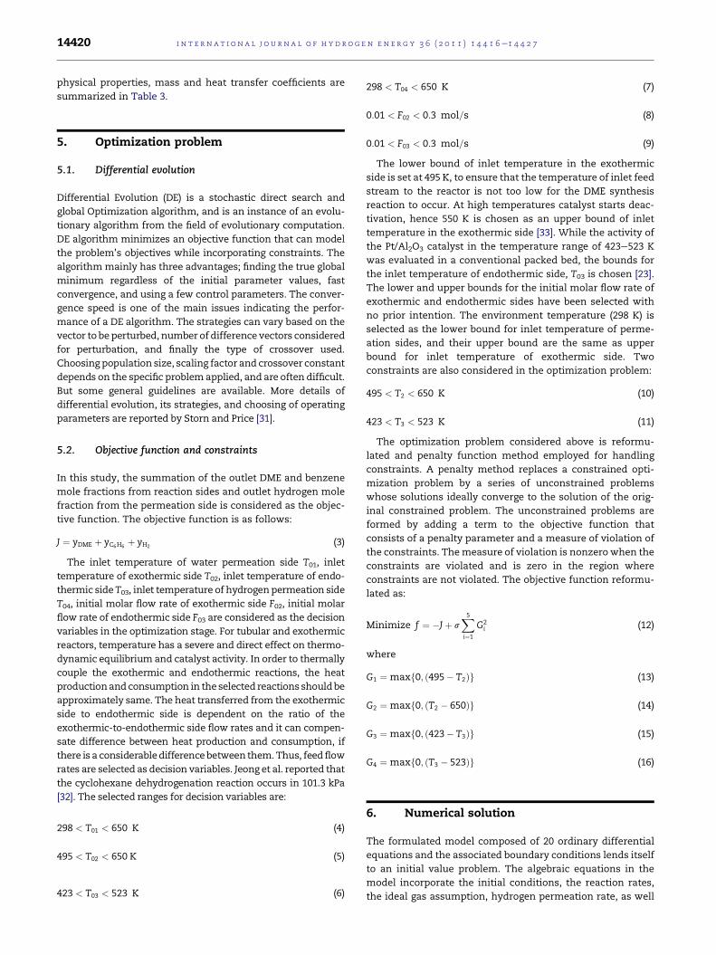
Fig. 3 e Comparison of methanol conversion in exothermic
side of OTCDMR and CADR and also, cyclohexane
conversion in endothermic side and hydrogen recovery
along the OTCDMR.
0.4
0.48
0.56
0.64
ctio
n
i n t e rn a t i o n a l j o u r n a l o f h y d r o g e n en e r g y 3 6 ( 2 0 1 1 ) 1 4 4 1 6e1 4 4 2 714422
An obvious measure to investigate the reactor performance
is how much heat has to be supplied through the exothermic
reaction to maintain the endothermic reaction. The relative
heat supply is defined by the fuel ratio j:
J ¼ available heat of exothermic reactionmaximum required heat of endothermic reaction
(20)
As efficiency of the reactor is defined by:
x ¼ heat actually consumed for endothermic reactionheat actually released for exothermic reaction
(21)
With attention to subjects of Section 5, the feed temperature
of all sides and feed flow rate of exothermic and endothermic
sides are considered as decision variables to maximize DME,
benzene and hydrogen mole fractions using differential
evolution method. The results of the optimization are
summarized in Table 6.
In Fig. 3, the comparison of methanol conversion in the
exothermic side of optimized thermally coupled dual-
membrane rector (OTCDMR) and conventional adiabatic
DME reactor (CADR), cyclohexane conversion in the endo-
thermic side along the OTCDMR are shown. Cyclohexane
conversion is 99.2% in the endothermic side. Also, methanol
conversion reaches 86.5% and 82% in the exothermic side of
OTCDMR and CADR, respectively. The comparison of meth-
anol conversion in OTCDMR and CADR shows that the
methanol conversion in output of OTCDMR increased about
5.5%. The important point in this figure is that the exothermic
reaction is under kinetic control at the reactor entrance and in
the other section, the rate of DME synthesis reaction has
decreased to its equilibrium value and reaction is under
equilibrium control. The reaction scheme for cyclohexane
dehydrogenation indicates that the hydrogen recovery
approaches the value of three if all cyclohexane is converted
to benzene. The right-hand side of Fig. 3 illustrates the
hydrogen recovery profile along the reactor axis for endo-
thermic side of OTCDMR. This reactor configuration leads to
hydrogen recovery yield 2.4. Overall, the optimized operating
parameters for this configuration lead to efficient coupling of
these two reactions for hydrogen production.
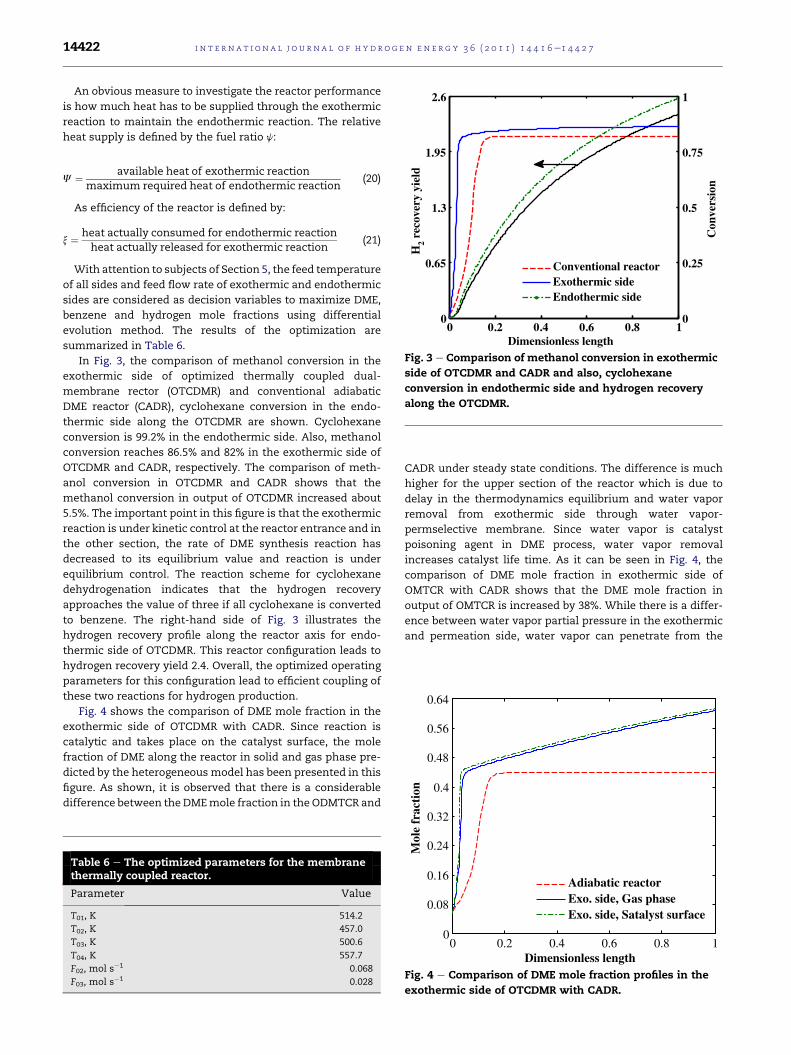
Fig. 4 shows the comparison of DME mole fraction in the
exothermic side of OTCDMR with CADR. Since reaction is
catalytic and takes place on the catalyst surface, the mole
fraction of DME along the reactor in solid and gas phase pre-
dicted by the heterogeneous model has been presented in this
figure. As shown, it is observed that there is a considerable
difference between the DMEmole fraction in the ODMTCR and
Table 6 e The optimized parameters for the membranethermally coupled reactor.
Parameter Value
T01, K 514.2
T02, K 457.0
T03, K 500.6
T04, K 557.7
F02, mol s�1 0.068
F03, mol s�1 0.028
CADR under steady state conditions. The difference is much
higher for the upper section of the reactor which is due to
delay in the thermodynamics equilibrium and water vapor
removal from exothermic side through water vapor-
permselective membrane. Since water vapor is catalyst
poisoning agent in DME process, water vapor removal
increases catalyst life time. As it can be seen in Fig. 4, the
comparison of DME mole fraction in exothermic side of
OMTCR with CADR shows that the DME mole fraction in
output of OMTCR is increased by 38%. While there is a differ-
ence between water vapor partial pressure in the exothermic
and permeation side, water vapor can penetrate from the
0 0.2 0.4 0.6 0.8 10
0.08
0.16
0.24
0.32
Mol
e fr
a
Dimensionless length
Adiabatic reactor Exo. side, Gas phaseExo. side, Satalyst surface
Fig. 4 e Comparison of DME mole fraction profiles in the
exothermic side of OTCDMR with CADR.

0 0.2 0.4 0.6 0.8 10
0.02
0.04
0.06
0.08
0.1
0.12M
ole
frac
tion
Dimensionless length
C6H12
H2
C6H6
Fig. 5 e Mole fraction profile of cyclohexane, benzene and
hydrogen along the reactor axis.
0 0.05 0.1 0.15 0.20
20
40
60
80
100
120
140
Dimensionless length
Rat
e of
rea
ctio
n fo
r D
ME
syn
thes
is, m
ol m
-3 s
-1
0
0.3
0.6
0.9
1.2
1.5
1.8
2.1
Rea
ctio
n ra
te f
or C
6H12
, mol
m-3
s-1
Fig. 7 e Variation of reaction rate in exothermic and
endothermic sides.
i n t e r n a t i o n a l j o u r n a l o f h y d r o g e n en e r g y 3 6 ( 2 0 1 1 ) 1 4 4 1 6e1 4 4 2 7 14423
reaction zone into the permeation side through composite
membrane layer.
Fig. 5 illustrates the mole fraction profile of cyclohexane,
benzene and hydrogen along the reactor axis, at steady state
for endothermic side of OTCDMR. Hydrogen permeation
from endothermic side to separation side results shifting
the dehydrogenation reaction to right and increases
hydrogen and benzene mole fractions. While there is
a difference between hydrogen partial pressure in the
endothermic and permeation side, hydrogen can continu-
ously pass from the endothermic side into the permeation
0 0.1 0.2 0.3 0.4 0.5430
470
510
550
590
630
660
Tem
pera
ture
, K
Dimensionless length
Adiabatic reactor
Exothermic side
H 2 O perm. side
Endothermic side
Hydrogen perm. side
Fig. 6 e Comparison of axial temperature profiles in the
exothermic side of OTCDMR with CADR and also,
temperature profiles of endothermic and permeation sides.
side. Thus, decreasing hydrogen partial pressure in the
permeation side causes higher decreasing hydrogen level in
the endothermic side.
Fig. 6 shows the temperature profiles in the exothermic
side, endothermic and permeation sides in OTCDMR
(dimensionless 0e0.5). In the CADR, the temperature profile
increases up to equilibrium temperature and after a certain
position along the reactor the temperature remains constant.
Thus, DME is not produced after equilibrium point in the
CADR and dehydration reaction rate approaches to zero. The
highest temperature in the OTCDMR is observed at the
exothermic side due to heat generation. The temperature of
0 0.05 0.1 0.15 0.2-5
0
5
10
15
20
25
30
Dimensionless length
Hea
t flu
x, W
Gene. heat in exothermic sideCons. heat in endothermic sideTran. heat from solid wallTran. heat from H2 membrane
Tran. heat from H2O membrane
Fig. 8 e Generated and consumed heat flux in exothermic
and endothermic side and transferred heat from solid
walls.
0 0.2 0.4 0.6 0.8 10
0.02
0.04
0.06
0.08
0.1
0.12
H2 m
ole
frac
tion
in m
embr
ane
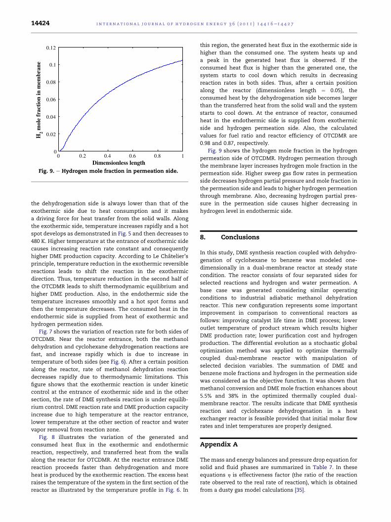
Dimensionless lengthFig. 9. e Hydrogen mole fraction in permeation side.
i n t e rn a t i o n a l j o u r n a l o f h y d r o g e n en e r g y 3 6 ( 2 0 1 1 ) 1 4 4 1 6e1 4 4 2 714424
the dehydrogenation side is always lower than that of the
exothermic side due to heat consumption and it makes
a driving force for heat transfer from the solid walls. Along
the exothermic side, temperature increases rapidly and a hot
spot develops as demonstrated in Fig. 5 and then decreases to
480 K. Higher temperature at the entrance of exothermic side
causes increasing reaction rate constant and consequently
higher DME production capacity. According to Le Chatelier’s
principle, temperature reduction in the exothermic reversible
reactions leads to shift the reaction in the exothermic
direction. Thus, temperature reduction in the second half of
the OTCDMR leads to shift thermodynamic equilibrium and
higher DME production. Also, in the endothermic side the
temperature increases smoothly and a hot spot forms and
then the temperature decreases. The consumed heat in the
endothermic side is supplied from heat of exothermic and
hydrogen permeation sides.
Fig. 7 shows the variation of reaction rate for both sides of
OTCDMR. Near the reactor entrance, both the methanol
dehydration and cyclohexane dehydrogenation reactions are
fast, and increase rapidly which is due to increase in
temperature of both sides (see Fig. 6). After a certain position
along the reactor, rate of methanol dehydration reaction
decreases rapidly due to thermodynamic limitations. This
figure shows that the exothermic reaction is under kinetic
control at the entrance of exothermic side and in the other
section, the rate of DME synthesis reaction is under equilib-
rium control. DME reaction rate and DME production capacity
increase due to high temperature at the reactor entrance,
lower temperature at the other section of reactor and water
vapor removal from reaction zone.
Fig. 8 illustrates the variation of the generated and
consumed heat flux in the exothermic and endothermic
reaction, respectively, and transferred heat from the walls
along the reactor for OTCDMR. At the reactor entrance DME
reaction proceeds faster than dehydrogenation and more
heat is produced by the exothermic reaction. The excess heat
raises the temperature of the system in the first section of the
reactor as illustrated by the temperature profile in Fig. 6. In
this region, the generated heat flux in the exothermic side is
higher than the consumed one. The system heats up and
a peak in the generated heat flux is observed. If the
consumed heat flux is higher than the generated one, the
system starts to cool down which results in decreasing
reaction rates in both sides. Thus, after a certain position
along the reactor (dimensionless length ¼ 0.05), the
consumed heat by the dehydrogenation side becomes larger
than the transferred heat from the solid wall and the system
starts to cool down. At the entrance of reactor, consumed
heat in the endothermic side is supplied from exothermic
side and hydrogen permeation side. Also, the calculated
values for fuel ratio and reactor efficiency of OTCDMR are
0.98 and 0.87, respectively.
Fig. 9 shows the hydrogen mole fraction in the hydrogen
permeation side of OTCDMR. Hydrogen permeation through
the membrane layer increases hydrogen mole fraction in the
permeation side. Higher sweep gas flow rates in permeation
side decreases hydrogen partial pressure and mole fraction in
the permeation side and leads to higher hydrogen permeation
through membrane. Also, decreasing hydrogen partial pres-
sure in the permeation side causes higher decreasing in
hydrogen level in endothermic side.
8. Conclusions
In this study, DME synthesis reaction coupled with dehydro-
genation of cyclohexane to benzene was modeled one-
dimensionally in a dual-membrane reactor at steady state
condition. The reactor consists of four separated sides for
selected reactions and hydrogen and water permeation. A
base case was generated considering similar operating
conditions to industrial adiabatic methanol dehydration
reactor. This new configuration represents some important
improvement in comparison to conventional reactors as
follows: improving catalyst life time in DME process; lower
outlet temperature of product stream which results higher
DME production rate; lower purification cost and hydrogen
production. The differential evolution as a stochastic global
optimization method was applied to optimize thermally
coupled dual-membrane reactor with manipulation of
selected decision variables. The summation of DME and
benzene mole fractions and hydrogen in the permeation side
was considered as the objective function. It was shown that
methanol conversion and DME mole fraction enhances about
5.5% and 38% in the optimized thermally coupled dual-
membrane reactor. The results indicate that DME synthesis
reaction and cyclohexane dehydrogenation in a heat
exchanger reactor is feasible provided that initial molar flow
rates and inlet temperatures are properly designed.
Appendix A
Themass and energy balances and pressure drop equation for
solid and fluid phases are summarized in Table 7. In these
equations h is effectiveness factor (the ratio of the reaction
rate observed to the real rate of reaction), which is obtained
from a dusty gas model calculations [35].
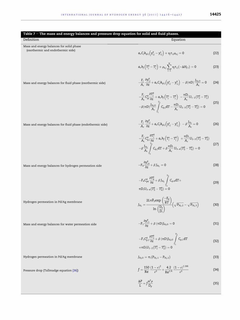
Table 7 e The mass and energy balances and pressure drop equation for solid and fluid phases.
Definition Equation
Mass and energy balances for solid phase
(exothermic and endothermic side)avCjkgi;j
�ygi;j � ys
i;j
�þ hjri;jrb;j ¼ 0 (22)
avhf
�Tgj � Ts
j
�þ rb;j
XNi�1
hjri;j��DHf ;i
� ¼ 0 (23)
Mass and energy balances for fluid phase (exothermic side) �Fj
Ac
vygi;j
vzþ avCjkgi;j
�ysi;j � yg
i;j
�� bðpDÞ JH2O
Ac¼ 0 (24)
�Fj
AcCgpj
vTgj
vzþ avhf
�Tsj � Tg
j
�� pDi
AcU1�2
�Tg2 � Tg
1
�
�bðpDÞ JH2O
Ac
ZT2
T1
Cp;jdT� pDi
AcU2�3
�Tg2 � Tg
3
� ¼ 0(25)
Mass and energy balances for fluid phase (endothermic side) �Fj
Ac
vygi;j
vzþ avCjkgi;j
�ysi;j � yg
i;j
�� b
JH2
Ac¼ 0 (26)
�Fj
AcCgp;j
vTgj
vzþ avhf
�Tsj � Tg
j
�þ pDi
AcU2�3
�Tg2 � Tg
3
�
�bJH2
Ac
ZT4
T3
Cp;jdTþ bpDi
AcU3�4
�Tg3 � Tg
4
� ¼ 0(27)
Mass and energy balances for hydrogen permeation side �F4
vygi;4
vzþ b JH2
¼ 0 (28)
�F4Cgp4
vTg4
vzþ b JH2
ZT4
T3
Cp;4dTþ
pDiU3�4
�Tg3 � Tg
4
� ¼ 0
(29)
Hydrogen permeation in Pd/Ag membraneJH2
¼2LpP0exp
��Ep
RT
�
ln
�Do
Di
� � ffiffiffiffiffiffiffiffiffiffiPH2 ;2
p � ffiffiffiffiffiffiffiffiffiffiPH2 ;3
p �(30)
Mass and energy balances for water permeation side �F1
vygi;1
vzþ b ðpDÞJH2O ¼ 0 (31)
�F1Cgp;1
vTg1
vzþ b ðpDÞJH2O
ZT2
T1
Cp;1dT
þpDiU1�2
�Tg1 � Tg
2
� ¼ 0
(32)
Hydrogen permeation in Pd/Ag membrane JH2O ¼ pi
�PH2 ;1 � PH2 ;2
�(33)
Pressure drop (Tallmadge equation [36]) f ¼ 150Re
ð1� εÞ2ε3
þ 4:2
Re1=6
ð1� εÞ1:166ε3
(34)
DPL
¼ fu2r
Dp(35)
i n t e r n a t i o n a l j o u r n a l o f h y d r o g e n en e r g y 3 6 ( 2 0 1 1 ) 1 4 4 1 6e1 4 4 2 7 14425
i n t e rn a t i o n a l j o u r n a l o f h y d r o g e n en e r g y 3 6 ( 2 0 1 1 ) 1 4 4 1 6e1 4 4 2 714426
Nomenclature
av Specific surface area of catalyst pellet, m2 m�3
Ac Cross section area of each tube, m2
C Total concentration, mol m�3
Ci Molar concentration of component i, mol m�3
Cp Specific heat of the gas at constant pressure,
J K�1 mol�1
dp Particle diameter, m
Di Tube inside diameter, m
Dij Binary diffusion coefficient of component i in j, m2 s�1
Dim Diffusion coefficient of component i in the mixture,
m2 s�1
Do Tube outside diameter, m
Ep Activation energy of permeability, J mol�1
F Total molar flow rate, mol s�1
hf Gas-solid heat transfer coefficient, W m�2 K�1
DHf,i Enthalpy of formation of component i, J mol�1
J Objective function
JH2 Hydrogen permeation rate in Pd/Ag membrane,
mol m�1 s�1
JH2O Water vapor permeation rate in composite
membrane, mol m�2 s�1
k Rate constant of dehydrogenation reaction,
mol m�3 Pa�1 s�1
k1 Rate constant for the rate of methanol dehydration
reaction, mol kg�1 s�1
kg Mass transfer coefficient for component i, m s�1
K Conductivity of fluid phase, W m�1 K�1
KB Adsorption equilibrium constant for benzene, Pa�1
Keq Reaction equilibrium constant for methanol
dehydration reaction, �Ki Adsorption equilibrium constant for component i
(CH3OH and H2O) in methanol dehydration reaction,
m3 mol�1
Kp Equilibrium constant for dehydrogenation reaction,
Pa3
Kw Thermal conductivity of reactor wall, W m�1 K�1
L Reactor length, m
N Number of components
P Permeability of hydrogen through Pd/Ag membrane,
mol m�2 s�1 Pa�1/2
P0 Pre-exponential factor of hydrogen permeability,
mol m�2 s�1 Pa�1/2
P Total pressure (for exothermic side: bar; for
endothermic side: Pa)
Pi Partial pressure of component i, Pa
r1 Rate of reaction for DME synthesis, mol kg�1 s�1
r2 Rate of reaction for dehydrogenation of cyclohexane,
mol m�3 s�1
R Universal gas constant, J mol�1 K�1
Re Reynolds number
Sci Schmidt number of component i
T Temperature, K
u Superficial velocity of fluid phase, m s�1
ug Linear velocity of fluid phase, m s�1
U Overall heat transfer coefficient between exothermic
and endothermic sides, W m�2 K�1
yi Mole fraction of component i, mol mol�1
z Axial reactor coordinate, m
Greek letters
aH Hydrogen permeation rate constant,
mol m�1 s�1 Pa�1/2
pi water permeation rate constant, mol m�2 s�1 Pa�1
m Viscosity of fluid phase, kg m�1 s�1
h Effectiveness factor
b Switch for component permeation from membrane
layer (0 and 1)
rb Density of catalytic bed, kg m�3
Superscripts
g In bulk gas phase
s At surface catalyst
0 Inlet conditions
i Chemical species
j Side of the coupled reactor (1: water-permselective
side, 2: exothermic side, 3: endothermic side, 4:
hydrogen-permselective side)
r e f e r e n c e s
[1] Troy AS, Rodney LB, Howard LG. Dimethyl ether (DME) as analternative fuel. J Power Sources 2006;156(2):497e511.
[2] Ng KL, Chadwick D, Toseland BA. Kinetics and modeling ofdimethyl ether synthesis from synthesis gas. Chem Eng Sci1999;54:3587e92.
[3] Lu WZ, Teng LH, Xiao WD. Simulation and experiment studyof dimethyl ether synthesis from syngas in a fluidized-bedreactor. Chem Eng Sci 2004;59:5455e64.
[4] Lu WZ, Teng LH, Xiao WD. Theoretical analysis of fluidizedbed reactor for dimethyl ether synthesis from syngas. Int JChem Reactor Eng 2003;1. Article S2.
[5] Farsi M, Eslamloueyan R, Jahanmiri A. Modeling, simulationand control of dimethyl ether synthesis in an industrialfixed-bed reactor. Chem Eng Process 2010;50(1):85e94.
[6] Farsi M, Jahanmiri A, Eslamlueyan R. Modeling andoptimization of MeOH to DME in isothermal fixed-bedreactor. Int J Chem Reactor Eng 2010;8. Article A79.
[7] Fazlollahnejad M, Taghizadeh M, Eliassi A, Bakeri G.Experimental study and modeling of an adiabatic fixed-bedreactor for methanol dehydration to dimethyl ether. Chin JChem Eng 2009;17(4):630e4.
[8] Agar DW. Multifunctional reactors: old preconceptions andnew dimensions. Chem Eng Sci 1999;54(10):1299e305.
[9] Khademi MH, Jahanmiri A, Rahimpour MR. A novelconfiguration for hydrogen production from coupling ofmethanol and benzene synthesis in a hydrogen permselectivemembrane reactor. Int J Hydrogen Energy 2009;34:5091e107.
[10] Khademi MH, Rahimpour MR, Jahanmiri A. Differentialevolution (DE) strategy for optimization of hydrogenproduction, cyclohexane dehydrogenation and methanolsynthesis in a hydrogen-permselective membrane thermallycoupled reactor. Int J Hydrogen Energy 2010;35:1936e50.
[11] Farsi M, Khademi MH, Jahanmiri A, Rahimpour MR. A novelrecuperative configuration for coupling of methanoldehydration to dimethyl ether with cyclohexanedehydrogenation to benzene. Ind Eng Chem Res 2010;49(10):4633e43.
[12] Khademi MH, Farsi M, Rahimpour MR, Jahanmiri A. DMEsynthesis and cyclohexane dehydrogenation reaction in an
i n t e r n a t i o n a l j o u r n a l o f h y d r o g e n en e r g y 3 6 ( 2 0 1 1 ) 1 4 4 1 6e1 4 4 2 7 14427
optimized thermally coupled reactor. Chem Eng Process2011;50(1):113e23.
[13] Lina YM, Leeb GL, Rei MH. An integrated purification andproduction of hydrogen with a palladiummembraneecatalytic reactor. Catal Today 1988;44:343e9.
[14] Lee KH, Youn MY, Sea B. Preparation of hydrophilic ceramicmembranes for a dehydration membrane reactor.Desalination 2006;191:296e302.
[15] Sea B, Lee KH. Synthesis of dimethyl ether from methanolusing aluminaesilica membrane reactor. Desalination 2006;200:689e91.
[16] Shirasaki Y, Tsuneki T, Ota Y, Yasuda I, Tachibana S,Nakajima H. Development of membrane reformer system forhighly efficient hydrogen production from natural gas. IntJ Hydrogen Energy 2009;34(10):4482. e7.
[17] Itoh N, Wu TH. An adiabatic type of palladium membranereactor for coupling endothermic and exothermic reactions.J Membr Sci 1997;124(2):213e22.
[18] Xu M, Goodman DW, Bhattacharyya A. Catalytic dehydrationof methanol to dimethyl ether (DME) over Pd/Cab-O-Silcatalysts. Appl Catal A: Gen 1997;149(2):303e9.
[19] Jun KW, Lee HS, Roh HS, Park AE. Catalyst dehydration ofmethanol to dimethyl ether (DME) over solid-acid catalysts.Bull Korean Chem Soc 2006;23(6):803e6.
[20] Bondiera J, Naccache C. Kinetics of methanol dehydration indealuminated H-Mordenite: model with acid and basic activecenters. Appl Catal 1991;69:139e48.
[21] Ber�ci�c G, Levec J. Intrinsic and global reaction rate ofmethanol dehydration over Al2O3 pellets. Ind Eng Chem Res1992;31:1035e40.
[22] Jeong BH, Sotowa KI, Kusakabe K. Catalytic dehydrogenationof cyclohexane
[23] Itoh N. A membrane reactor using palladium. AIChE J 1987;33:1576e8. in an FAU-type zeolite membrane reactor.J Membr Sci 2003; 224: 151e158.
[24] Lindsay AL, Bromley LA. Thermal conductivity of gasmixture. Ind Eng Chem 1950;42:1508e10.
[25] Poling BE, Prausnitz JM, O’Connell JP. The properties of gases& liquids. New York: McGraw-Hill; 2001.
[26] Cussler EL. Diffusion, mass transfer in fluid systems.Cambridge: University Press; 1984.
[27] Hirschfelder JO, Curtis CF, Bird RB. Molecular theory of gasesand liquids. New York: John Wiley and Sons; 1952.
[28] Wilke CR. Diffusional properties of multi-component gases.Chem Eng Prog 1950;46(2):95e104.
[29] Dittus FW, Boelter LMK. Publications in engineering.University of California; 1930.
[30] Dwivedi PN, Upadhyay SN. Particle-fluid mass transfer infixed and fluidized beds. Ind Eng Chem. Process Des Dev1977;16(2):157e65.
[31] Storn R, Price K. Differential evolution, a simple and efficientheuristic for global optimization over continuous spaces.J Glob Optimization 1997;11:341e59.
[32] Jeong BH, Sotowa KI, Kusakabe K. Modeling of an FAU-type zeolite membrane reactor for the catalyticdehydrogenation of cyclohexane. Chem Eng J 2004;103:69e75.
[33] Yaripour F, Baghaei F, Schmidt I, Perregaard J. Catalyticdehydration of methanol to dimethyl ether (DME) over solid-acid catalysts. Catal Commun 2005;6:147e52.
[34] Dormand JR, Prince PJ. A family of embeddedRungeeKutta formulae. J Computational Appl Math 1980;6:19e26.
[35] Khademi MH, Setoodeh P, Rahimpour MR, Jahanmiri A.Optimization of methanol synthesis and cyclohexanedehydrogenation in a thermally coupled reactor usingdifferential evolution (DE) method. Int J Hydrogen Energy2009;34:6930e44.
[36] Tallmadge JA. Packed bed pressure drop, an extension tohigher Reynolds numbers. AIChE J 1970;16(6):1092e3.