master - university of hawaii · geysers. a source of recharge ... this stress is usually....
TRANSCRIPT

~ !..{ "'LA"-UR.-7·3 "-1· 61'9. .,5:..4 '.
,I .
ARTIFICIAL GEOTHERMAL RESERVOIRS IN HOT VOLCANIC ROCK*
by
R. Lee Aamodt
Geothermal Energy GroupUniversity of California
Los Alamos Scientific LaboratoryLos Alamos, New Mexico 87544
(A talk to be presented at the U.S.-Japan Cooperative ScienceSeminar on "The Utilization of Volcano Energy" in Hilo, Hawaii,on February 4-8, 1974. Sponsored by the Japan Society for thePromotion of Science and the United States National ScienceFoundation.)
r------NOTI CE- ---,This report was prepared as an account of worksponso~ed by the United States Government. Neitherthe UR1t~d States nor the United States Atomic EnergyC0--:nmisslon, nor any of their employees, nor any ofthell contractors, subcontractors, or their employeesmakes anr. warranty t express or implied, or assumes an;legal liabIlity or responsibility for the accuracy. com.pleteness or usefulness of any information apparatusproduct or process disclosed, or represents'that its us~would not Infringe privately owned rights.
*This work is being done under the auspices of the U. S.AtomicEnergy Commission.
MASTER~1~RI8UTION OF THiS DOCUMENT IS UNLI~

...
u ARTIFICIAL GEOTHERMAL RESERVOIRS IN HOT VOLCANIC ROCK
by
R.· Lee Aamodt
I. INTRODUCTION
If there exists a sustained, reliable 'heat source in or neara volcano, it must be ,at some depth since lava pools in volcaniccraters are only intermittently full. Lava lakes may be a partialexception to this rule, but their life appears to be limited to afew tens of years. There may exist more permanent pools of lavaat depths of a few kilometers. Even these must have transientfluctuations as pressure builds up and recedes. However, ifchanges in the properties of the lava, such as viscosity, are nottoo great, and if rock movement does not destroy the energy ex.traction system too frequently, these pools may be attractiveenergy sources. Additionally, the rock surrounding such pools.of lava may store heat over long times, and be relatively freeof short term temperature fluctuations. This will only be trueif the transport of heat out of the rock by steady or ,intermittentflow of water is sufficiently slow.
If such masses of rock at elevated temperature exist aroundunderground lava pools, it may be possible and even advantageousto extract the heat from the rock instead of the lava. The meansfordoing this will be quite different from those designed toextract energy directly from molten magma.. In general, the temper-'ature of the rock will be lower, a much larger area of controlbetween the heat exchange fluid and the rock will be necessary,and problems of solution, precipitation, and corrosion may'beexpected to decrease as the temperature is reduced.
"

u The Los Alamos Scientific Laboratory is conducting an experiment about 4 kilometers west and south of the ring fault of theenormous Jemez Caldera in the northcentral part of the state ofNew Mexico. The experiment is designed to demonstrate that geothermal energy may be extracted from hot rock which does not contain circulating hot. water or steam, and which is relativelyimpermeable. If successful, the experiment will help free thegeothermal energy program from dependence on fortuitous geologiccircumstances and show that man can engineer systems which providethe necessary circumstances for extraction of geothermal energywhere nature has failed to do so. The purpose of this paper isto describe some recent results from the Los Alamos Program and
discuss the circumstances under ~hichartificial geothermal reser-. voirs might be created in the basaltic rock of Hawaii.
II. NATURAL GEOTHERMAL RESERVOIRS
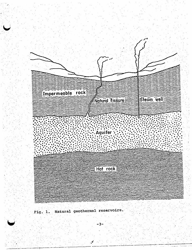
When the requisite geological features fortuitously occurtogether, a natural geothermal reservoir is formed. These featuresare shown in Fig. 1. A source ~f heat, such as a recent magmaticinstrusion, lies below a permeable zone containing water which has
been heated by circulation over the heat source. Overlying thepermeable zone is a layer of impermeable cap rock•.The majormechanism for heat loss from the reservoir is conduction throughthe cap rock, although some heat may be lost through' springs orgeysers. A source of recharge water, usually an inflow of groundwater from the sides, must exist. If the recharge rate is sufficiently slow, there may be a vapor phase overlying a liquid phaseand a well drilled through the cap rock may deliver dr~ steam.More commonly, the well delivers hot "later ,which may boil in .thewellbore as it nears the surface. At the surface, the un~oiled
. water may be allowed to flash to steam at or slightly above thedesign pressure of the turbines. If the water is saline, thewell bore may clog rapidly with salts which are precipitated when
-2-
..
"
00••
0••••• 0 • 0
.OO(l •••• (l6(1~0 0.0° .. - 0 • 0 •• 0 ••°.0 ··00·· •••• 0. • • " •• "II 0"0 •• °0 •••• ° ••• ° •••••• 0. 0 •• ··0···· ....... " O"••• ~.~.'.',),)
00
.°. "•• ". o. (I•• "0••:. :. D • (I •• 00 " (I • 0 ° •••• ° • 0 0 • • , O· • 0 ° 0 ° • 00
C • e c° • ° .0" ° ° ° 0 .00 ••••00.0 0 o.: o. • o••• :::'.:'. ° 00 •• • 0" o· ° 0. : : • • : ••·0:'.' 0 • 0 0. 0" ': .. "':' : 0". •_.*::o".:tt.C:.:.:.o .•OOO.:::.Oo ':,.":.0 •• : •• 0 :0
• ,,·0 .,,·••• ... ·0·:.· ·:0 •• ~·0.0 : •• 00
•• '; ·,,·0,",• • 0". • 0 •• ° " eO 0.'· • ·00. 0•• ° 0 0." ° 0 cOo" 0·0 ,. ". "' ~.,.
o '. ° " •• 0°.·, 0.· ° 0" 0 0 0 •• • • 0 0 • 0 ". (I ° • • 0 o. • ° .. c·,,· ".0
• • .. o. -'" ~ 0 0 0 ' • 0 0 • 0 ." ... 0 0 0 , 0 • •• • 0 • • .' ~ 0 0 0 0 0 •• .·0 ..0. • .... ;' ••C " ~ .. ° •
•• 0- • • • •• • 0 0 0 •• AqUIfer )-. ... · CII .. D .l 0 0 • 0 .•• ~ ., "J. •
....... ". ..0 •• • • 0 0 ••• 0 0 (I. o. o. 0 • c • ..." ,) • .. ° • (I .. : • D • • ... ..... ~ .. " • .0 •.0. ._ 0 ••• _0 o •• 0.. - _ . 0 0.' 0. 0 {Jet 0 -0 0" "• : • (I 0 •• 0 0.0... 0 D • 0 • • ••• ~ ••• • 0 ".0 0" ". 0" (I 0 .c,. .. 0. • 0".0.. .. D." .. " 0.. " ~ ..
"0. 0 • 0 .. ,). • • •• 0 • • •• •• • 0 0 .. " 0 o· ° ° 0 0. 0 • • 0 0" 0.. 0· .. ' o' .. "" "." "'0":°
0°••• 0:. ~.o,.oo ••"'.·o· •• 6 0 /00"0'. (I : ....°0 ••°.::.:." : ..o:ooooo.",."~.,".. (1""
.•• 0.0
000
.'0°"0" 0 0 .0 0 ••• 0,) '.6 ·0 •• 00.·" 0·"011 ,,' o·
.. 0" ••0. 0 .""." 0 0 0 (I (I 0 .0 •: o' .. 0 0 •• • :0 C; 0 0 (I~. • l' .' 0 •• ,). o. 6°.. ° ' " •• • " .' .. " ...... ,,0 • o. " .. 0 co • 0 .. o. ° 0". (I " o. 0 .,. ~.. .. ~ °0 • 0·. 0 '" 0 0 • " 0 • •• 0·· ... " "0 ...... ° •'" •• 0 •• 0 • 0 0" .00.°0. '0' .0000to 0 " ···.0 00
00° o· • ° 11 .•. "0
0.,"
.. ° 0" • ". " 0 0: ~ 11" 0:. • 0." o. 0 it. D. 0 ...... ° 0:: II ~ , • • •• "" •.• : 0- .. " •. :."ooo"~ - ,- •.• ,.,,~<-
Fig. 1. Natural geothermal reservoirs.
-3-
.._-----~.;. ~_...__.__.~ ..-----,-_..,._~--------:=-----. -.-.:-..----:--""" ---------_._--~.-
..
U part of the water is vaporized. In such case, a downhole pump
may be required to pressurize the upper part of the we1lbore and
prevent boiling. Another alternative is to pass the water througha heat exchanger. The heat is transferred to a working fluid,which may be pure water or an organic vapor. This working fluid
drives the turbine. In such a system, the geothermal water isnever allowed to flash to steam, and may be reinjected back intothe reservoir along with any noncondensib1e gases such as H2Swhich are dissolved in it with obvious environmental advantages.
III. ARTIFICIAL GEOTHERMAL RESERVOIRS
A. Area of Contact Between Fluid and Hot Rock
A natural reservoir may be viewed as a hot-rock heat exchanger.Most of the energy in such a reservoir, as much as 85 to 90 percent of it, ·isin the rock (White 1973). Rock is a poor heat
conductor; if the temperature at a rock face is lowered it maytake a year for the resulting cooling wave to penetrate 6 to 10
meters into the rock. Thus, a hot-rock heat exchanger for geothermal use must provide a few square kilometers of contact area
between the rock and the circulating fluid if it is to delivertens of megawatts of geothermal heat energy (Smith et aI, 1973).If a mass of rock contains pre-existing fractures, a large contactarea is available naturally. If the rock is relatively impermeable, large cracks may be created by the process of hydraulic
fracturing, which is described below.
B. Hydraulic Fracturing
To create a hydraUlic fracture, a fluid is pumped at high
pressure into an isolated section of a wellbore, where it is"allowed to contact the surrounding rock. If the well is cased,the pipe in this pressurized region is perforated by methodsfamiliar in the petroleum industry, so that.the pressure may beapplied to the rock. As the pressure increases, the rock goes
-4-
..

.'
,.
~ into tension and eventually cracks. The crack may be enlargedto form a large, pancake shaped fracture by pumping more fluidinto it. If the crack is deeper than a few hundred meters, it
will usually be oriented so that it opens against the·leastprincipal earth stress. This stress is usually. horizontal, andthe crack is vertical· (Hubbert, 1957).
C. Circulation System
A second well is drilled a few hundred feet away from thefirst, and deviated by standard techniques to intersect thefracture near the top as shown in Fig. 2. Cold water is injectedthrough the first pipe, circulates through the crack, and hotwater returns to the surface through the second pipe. The watermay be allowed to flash to vapor in the reservoir, but this en
tails several disadvantages •. The first is that dissolved materials may b~ deposited on the walls and close off the circulationsystem. The second is that the viscosity of steam increases withtemperature, so that it will preferentially choose the colder oftwo otherwise similar paths, while the opposite is true for water.The third disadvantage of steam is that in a given wellbore, witha given temperature and driving pressure, a steam well deliversmuch less·energy to the surface than a hot water well (S~ith etaI, .1973). The favored operating mode for the circulation systemis one in which the heat conducting fluid is kept under sufficientpressure so that it never vaporizes. The fluid passes through aheat exchanger at the surface and is then reinjected into thecrack. A second working fluid, which may be water, is heated inthe heat exchanger to drive a turbine or to provide process heat,etc. Problems of precipitation and scale formation are thus concentrated at the heat exchanger.
D. Earth Stress Balance
The internal pressure in the crack varies with depth, as doesthe external earth stress. If the difference between·· earth stress
-5-
..

u
TOP'VIEWo•I•I••:I :
I !. JI ..i I
FRONT VIEW SIDE VIEW·
'SYSTEM FOR CIRCULATING LIQUIDCOOLANT THROUGH CRACK
V Fig. 2. Artificial geothermal reservoir.
-6-.

and internal pressure were constant, the pressure differencerequired to extend the crack is given by the equation (Sack, 1946).
p-s = {1T<X E/[2R(1 "_ ,,2)]}~
P - p~essure of fluid in crack.S - least principal earth stress, normal to crack.<X - energy required to form unit area of crack surface.
R - radius of crack.•
E Young's modulus of rock.
" - Poisson's ratio of rock.
(1)
If the difference between internal pressure and the least principal earth stress is greater than this, the crack will. grow. Itis very desirable' to hold the crack open by pressure, in order toreduce resistance to flow. In order to do this, the differencebetween internal pressure and earth stress near the top of thecrack should match the corresponding difference at the bottom ofthe crack as nearly as possible. The pressure must be greater .~han the earth stress to open the crack, yet the difference anywhere inside the crack cannot exceed (1) or.the crack will notbe stable. The difference between P and S at the top and bottomof the crack maybe reduced by controlling the density of thecirculating fluid. This density may be controlled by choosingfluids other than water, if lower density than that of water isneeded, or by dissolving substances in water to increase itsdensity. In some cases, it may be desirable to increase thedensity with suspended solids. In order to determine the required
. density, the earth stress should be measured-vs depth in a-numberof small fractures before the very large fracture is created.'
-7-
...
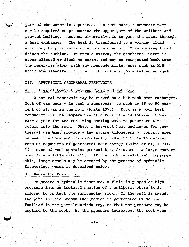
·'E. Measurement 'o'f" Earth'Stre'ss
Figure 3 shows data from which the earth stress in a Los
Alamos exploratory hole was determined. The pressure data were
taken after a hydraulic fracture was made in granite at'a meandepth of 760 meters and the well was shut in. ,Approximately.4000 liters of water 'were injected, at a pressure about 240 barsabove the estimated overburden weight.
The first plateau in Fig. 3 is interpreted as sho~ing thata horizontal -fracture had been created as well as a verticalfracture (numerous small vertical fractures had previously beencreated at lower pressures in the same wellbore). For approxi
mately3 hours, the pressure was maintained near the estimated
overburden pressure, while water was passing into the verticalfracture, which continued to grow, and out of the wellbore
through a leaking packer. When the horizontal fracture emptied,the pres~ure dropped to a value above the least principal stress
, ,
S. Just as the vertical crack closed, the pressure was S = 137
bars, in reasonable agreement with a value of 147 bars obtained
by a different method.
F. Limit on Size of Stable Crack
As Rincreases,Eq. (1) shows that the value of P-S at whicha crack' extends is reduced. At the same time, deviation of theleast principal stress, S, from values that may pe compensated
by adjusting the density of the circulating liquid becomes moreprobable. It is thus likely that a maximum stable crack radiusexists. If this radius does not provide sufficient· heat transfer·surface, a meth~d of producing multiple parallel fractures exists,as.shownin Fig. 4 (this method was independently suggested by
Barry Raleigh of the U.S.G.S.).
G. Thermal Stress Cracking
Another possible way out of the limit on the size of a single
crack arises from thermal stress cracking. As energy is with
drawn from the rock, the rock is cooled and contracts. This
-8-
,'.

.' .
(' (:
400300200Time (min)
808 Oe 00 8 eo 0 e/Horizontal fracture emptiese' .
~. ..8
'''0••-e~J)"" G .0 e
. " f) 0,Vertical fracture· empties/' e
oo
~
.(f)
C 200. .0'
"-""
•
Fig. 3. Pressure vs time in well 'after hydraulic fracturing •
. .. ;

..,.
Fig. 4. Multiple hydraulic fractures in single we11bore •
-10-
ALTERNATIVE WELL II. FOR CIRCULATION II
LOOP IIIIIIIIII
IJ '-If ..-/;~
?~~ .
-==='== -=-=-=--=-= ==:='::= ==:::::~
HYDRAULIC "FRACTURES "IN
51 N GLEWELL- BORE
LEASTPRINCIPALSTRESS
>
DIRECTION OF LEAST.PRINCIPAL STRESSDETERMINED HEREBEFORE DIRECTIONALDRILLING IS BEGUN.
..~.
" .

..
contraction eventually causes new cracks in the face of the
original one. Computer calculations (Harlow and Pracht, 1972)show that the reservoir grows fasted where the coldest waterencounters the hottest rock, i.e., downward and outward from the·face of the crack.· Experiments are needed to determine theactual rate of growth of artificial reservoirs "by this mechanism... .
H. Other Options for Creating Artificial Reservoirs
If the variation of earth stress with depth is erratic, asmight well be the case near a volcano, a mode of operation knownas the "Huff-Puff" method may be used, as was suggested by
. Robert Rex (Private communication, 1971). In this system, wateris pumped into a crack for some time, and then allowed to returnthrough the same pipe which should be insulated from the surrounding rock. If the upcoming water is cooled in a heat exchangerand flows into a second large fracture, continuous power generationcan be achieved with a small additional storage volume on the
surface.
If reservoirs are leaky and cannot sustain the overpressurenecessary to keep the surface water in liquid form, a downhole .pump may be used in the hot line.
Finally, ,if the reservoir of hot rock is truly porous, oneor more injection wells near the withdrawal well may be used.Such a system obviously grades over into. a conventional hot waterwell with reinjection.
-11-
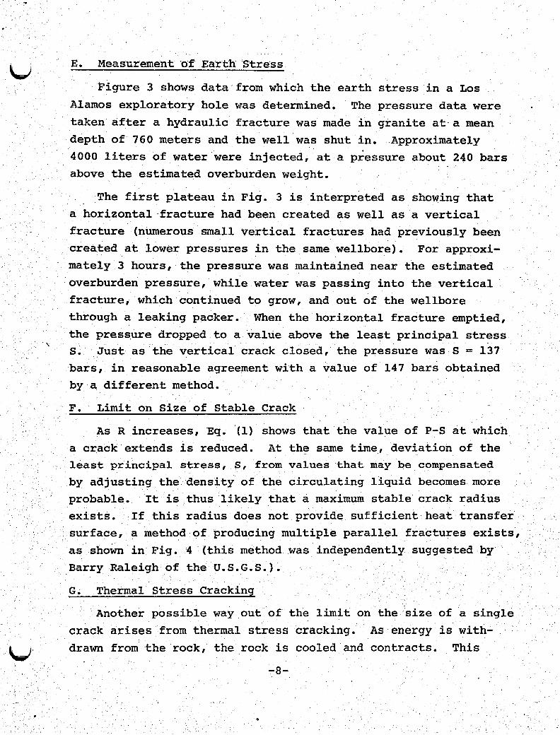
U REFERENCES
R. A. Sack, "Extension of Griffith's Theory of Rupture to ThreeDimensions," Proc. Phys. Soc. of London 58, 729 (1946).
M. King Hubbert and David G. Willis,· "Mechanics of HydraulicFracturing," Pet. Trans. AIME 210, 153-166 .(1957) ..
M. C. Smith, R. M. Potter, D. W. Brown, and R. L.Aamodt,IIInduction and Growth of Fractures in Hot Rock," GeothermalEnergy, Paul Kruger and Carel Otte, Eds. (Stanford UniversityPress, 1973), p 25l-26~.
Donald E•. White, "Characteristics of Geothermal Resources,"Geothermal Energy, Paul Kruger and Carel Otte, Eds. (Stanforduniversity Press, 1973), p 85.
,-,..
-:-12-
..