master of the digital method - elektron.se · here’s how: combine fm sound generation with a...
TRANSCRIPT
DigitoneMaster of the digital method
Quick Guide


3
THANK YOUThank you for purchasing Digitone. Digitone represents our vision of how FM synthesis can be revitalized and modernized. Here’s how: combine FM sound generation with a classic subtractive synthesis signal flow. You go from jagged chaos to mellow soundscapes in less than a second. Digitone is one unique box.
Choose from multiple FM algorithms featuring carefully selected parameters. Shape the tones with powerful filters. Arrange them with the intuitive Elektron sequencer, and then round it all off with the stellar effects. Now enjoy the most spectacular sounds, seemingly emanating from some parallel universe.
Become the master of the digital method!
- The Elektron Team
Digitone
4
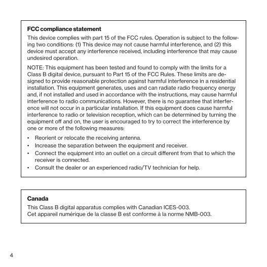
FCC compliance statementThis device complies with part 15 of the FCC rules. Operation is subject to the follow-ing two conditions: (1) This device may not cause harmful interference, and (2) this device must accept any interference received, including interference that may cause undesired operation.
NOTE: This equipment has been tested and found to comply with the limits for a Class B digital device, pursuant to Part 15 of the FCC Rules. These limits are de-signed to provide reasonable protection against harmful interference in a residential installation. This equipment generates, uses and can radiate radio frequency energy and, if not installed and used in accordance with the instructions, may cause harmful interference to radio communications. However, there is no guarantee that interfer-ence will not occur in a particular installation. If this equipment does cause harmful interference to radio or television reception, which can be determined by turning the equipment off and on, the user is encouraged to try to correct the interference by one or more of the following measures:
• Reorient or relocate the receiving antenna.• Increase the separation between the equipment and receiver.• Connect the equipment into an outlet on a circuit different from that to which the
receiver is connected.• Consult the dealer or an experienced radio/TV technician for help.
CanadaThis Class B digital apparatus complies with Canadian ICES-003. Cet appareil numerique de la classe B est conforme a la norme NMB-003.
5
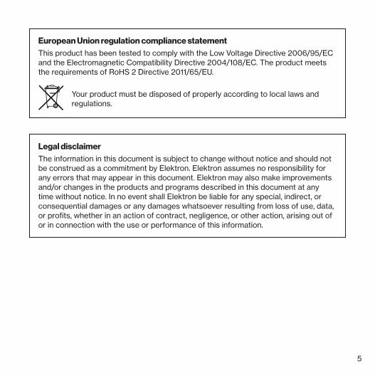
Legal disclaimerThe information in this document is subject to change without notice and should not be construed as a commitment by Elektron. Elektron assumes no responsibility for any errors that may appear in this document. Elektron may also make improvements and/or changes in the products and programs described in this document at any time without notice. In no event shall Elektron be liable for any special, indirect, or consequential damages or any damages whatsoever resulting from loss of use, data, or profits, whether in an action of contract, negligence, or other action, arising out of or in connection with the use or performance of this information.
European Union regulation compliance statementThis product has been tested to comply with the Low Voltage Directive 2006/95/EC and the Electromagnetic Compatibility Directive 2004/108/EC. The product meets the requirements of RoHS 2 Directive 2011/65/EU.
Your product must be disposed of properly according to local laws and regulations.

6
IMPORTANT SAFETY INSTRUCTIONS
1. Do not use the unit near water.2. Never use aggressive cleaners on the casing or on the screen. Remove dust, dirt
and fingerprints with a soft, dry and non-abrasive cloth. More persistent dirt can be removed with a slightly damp cloth using only water. Disconnect all cables before doing this. Only reconnect them when the product is safely dry.
3. Install in accordance with the manufacturer’s instructions. Make sure you place the unit on a stable surface before use.
4. Connect the unit to an easily accessible electrical outlet close to the unit.5. When transporting the unit, preferably use accessories recommended by the manufac-
turer or the box and padding the unit was originally shipped in.6. Do not install near any heat sources such as radiators, heat registers, stoves, or any
other appliance (including amplifiers) emitting heat.7. Do not put the PL-2S Protective Cover (Elektron accessory) on the unit while the unit is
powered on.8. This product, in combination with an amplifier and speakers or headphones, is capable
of producing sound levels that can cause permanent hearing loss. Do not operate for a long period of time at a high volume level or at a level that is uncomfortable.
9. Protect the power cord from being walked on or pinched particularly at plugs, convenience receptacles, and the point where they exit from the unit.
10. Only use attachments/accessories specified by the manufacturer.11. Unplug this unit during lightning storms or when it is not used for an extended time.12. Refer all servicing to qualified service technicians. Servicing is required when the unit
has been damaged in any way, liquid has been spilled or objects have fallen into the unit, the unit has been exposed to rain or moisture, does not operate normally, or has been dropped.
7
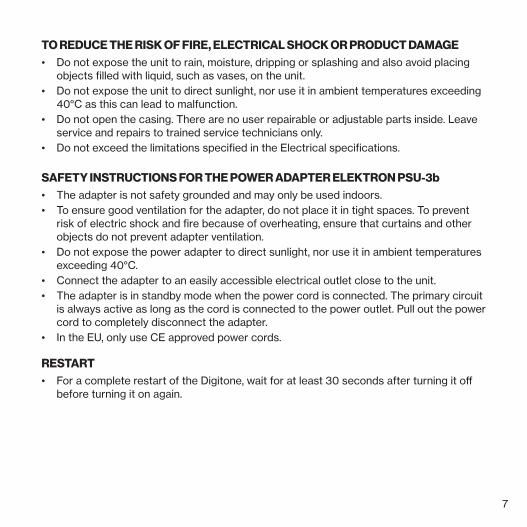
TO REDUCE THE RISK OF FIRE, ELECTRICAL SHOCK OR PRODUCT DAMAGE• Do not expose the unit to rain, moisture, dripping or splashing and also avoid placing
objects filled with liquid, such as vases, on the unit.• Do not expose the unit to direct sunlight, nor use it in ambient temperatures exceeding
40°C as this can lead to malfunction.• Do not open the casing. There are no user repairable or adjustable parts inside. Leave
service and repairs to trained service technicians only.• Do not exceed the limitations specified in the Electrical specifications.
SAFETY INSTRUCTIONS FOR THE POWER ADAPTER ELEKTRON PSU-3b• The adapter is not safety grounded and may only be used indoors.• To ensure good ventilation for the adapter, do not place it in tight spaces. To prevent
risk of electric shock and fire because of overheating, ensure that curtains and other objects do not prevent adapter ventilation.
• Do not expose the power adapter to direct sunlight, nor use it in ambient temperatures exceeding 40°C.
• Connect the adapter to an easily accessible electrical outlet close to the unit.• The adapter is in standby mode when the power cord is connected. The primary circuit
is always active as long as the cord is connected to the power outlet. Pull out the power cord to completely disconnect the adapter.
• In the EU, only use CE approved power cords.
RESTART• For a complete restart of the Digitone, wait for at least 30 seconds after turning it off
before turning it on again.
8
TABLE OF CONTENTS
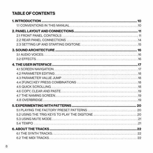
1. INTRODUCTION ..................................................................................................................... 101.1 CONVENTIONS IN THIS MANUAL . . . . . . . . . . . . . . . . . . . . . . . . . . . . . . . . . . . . . . . . . . . . . .10
2. PANEL LAYOUT AND CONNECTIONS .............................................................................. 112.1 FRONT PANEL CONTROLS . . . . . . . . . . . . . . . . . . . . . . . . . . . . . . . . . . . . . . . . . . . . . . . . . . . 112.2 REAR PANEL CONNECTIONS . . . . . . . . . . . . . . . . . . . . . . . . . . . . . . . . . . . . . . . . . . . . . . . .142.3 SETTING UP AND STARTING DIGITONE . . . . . . . . . . . . . . . . . . . . . . . . . . . . . . . . . . . . . . . 15
3. SOUND ARCHITECTURE .................................................................................................... 163.1 AUDIO VOICES . . . . . . . . . . . . . . . . . . . . . . . . . . . . . . . . . . . . . . . . . . . . . . . . . . . . . . . . . . . . . . . .163.2 EFFECTS. . . . . . . . . . . . . . . . . . . . . . . . . . . . . . . . . . . . . . . . . . . . . . . . . . . . . . . . . . . . . . . . . . . . .16
4. THE USER INTERFACE .........................................................................................................174.1 SCREEN NAVIGATION . . . . . . . . . . . . . . . . . . . . . . . . . . . . . . . . . . . . . . . . . . . . . . . . . . . . . . . . . 174.2 PARAMETER EDITING . . . . . . . . . . . . . . . . . . . . . . . . . . . . . . . . . . . . . . . . . . . . . . . . . . . . . . . .184.3 PARAMETER VALUE JUMP . . . . . . . . . . . . . . . . . . . . . . . . . . . . . . . . . . . . . . . . . . . . . . . . . . .184.4 [FUNC] KEY PRESS COMBINATIONS . . . . . . . . . . . . . . . . . . . . . . . . . . . . . . . . . . . . . . . . .184.5 QUICK SCROLLING. . . . . . . . . . . . . . . . . . . . . . . . . . . . . . . . . . . . . . . . . . . . . . . . . . . . . . . . . . .184.6 COPY, CLEAR AND PASTE . . . . . . . . . . . . . . . . . . . . . . . . . . . . . . . . . . . . . . . . . . . . . . . . . . . .194.7 THE NAMING SCREEN . . . . . . . . . . . . . . . . . . . . . . . . . . . . . . . . . . . . . . . . . . . . . . . . . . . . . . . .194.8 OVERBRIDGE . . . . . . . . . . . . . . . . . . . . . . . . . . . . . . . . . . . . . . . . . . . . . . . . . . . . . . . . . . . . . . . .19
5. EXPERIMENTING WITH PATTERNS ............................................................................... 205.1 PLAYING THE FACTORY PRESET PATTERNS . . . . . . . . . . . . . . . . . . . . . . . . . . . . . . . . . 205.2 USING THE TRIG KEYS TO PLAY THE DIGITONE . . . . . . . . . . . . . . . . . . . . . . . . . . . . . 205.3 USING MUTE MODE . . . . . . . . . . . . . . . . . . . . . . . . . . . . . . . . . . . . . . . . . . . . . . . . . . . . . . . . . .215.4 TEMPO . . . . . . . . . . . . . . . . . . . . . . . . . . . . . . . . . . . . . . . . . . . . . . . . . . . . . . . . . . . . . . . . . . . . . .21
6. ABOUT THE TRACKS ...........................................................................................................226.1 THE SYNTH TRACKS . . . . . . . . . . . . . . . . . . . . . . . . . . . . . . . . . . . . . . . . . . . . . . . . . . . . . . . . . 226.2 THE MIDI TRACKS . . . . . . . . . . . . . . . . . . . . . . . . . . . . . . . . . . . . . . . . . . . . . . . . . . . . . . . . . . . 22
9
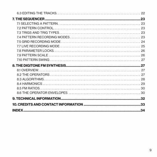
6.3 EDITING THE TRACKS . . . . . . . . . . . . . . . . . . . . . . . . . . . . . . . . . . . . . . . . . . . . . . . . . . . . . . . 22
7. THE SEQUENCER ..................................................................................................................237.1 SELECTING A PATTERN . . . . . . . . . . . . . . . . . . . . . . . . . . . . . . . . . . . . . . . . . . . . . . . . . . . . . . 237.2 PATTERN CONTROL . . . . . . . . . . . . . . . . . . . . . . . . . . . . . . . . . . . . . . . . . . . . . . . . . . . . . . . . . 237.3 TRIGS AND TRIG TYPES . . . . . . . . . . . . . . . . . . . . . . . . . . . . . . . . . . . . . . . . . . . . . . . . . . . . . 237.4 PATTERN RECORDING MODES . . . . . . . . . . . . . . . . . . . . . . . . . . . . . . . . . . . . . . . . . . . . . . 237.5 GRID RECORDING MODE . . . . . . . . . . . . . . . . . . . . . . . . . . . . . . . . . . . . . . . . . . . . . . . . . . . . 247.7 LIVE RECORDING MODE . . . . . . . . . . . . . . . . . . . . . . . . . . . . . . . . . . . . . . . . . . . . . . . . . . . . . 257.8 PARAMETER LOCKS . . . . . . . . . . . . . . . . . . . . . . . . . . . . . . . . . . . . . . . . . . . . . . . . . . . . . . . . . 267.9 PATTERN SCALE . . . . . . . . . . . . . . . . . . . . . . . . . . . . . . . . . . . . . . . . . . . . . . . . . . . . . . . . . . . . 267.10 PATTERN SWING . . . . . . . . . . . . . . . . . . . . . . . . . . . . . . . . . . . . . . . . . . . . . . . . . . . . . . . . . . . 27
8. THE DIGITONE FM SYNTHESIS......................................................................................... 278.1 OVERVIEW. . . . . . . . . . . . . . . . . . . . . . . . . . . . . . . . . . . . . . . . . . . . . . . . . . . . . . . . . . . . . . . . . . . 278.2 THE OPERATORS . . . . . . . . . . . . . . . . . . . . . . . . . . . . . . . . . . . . . . . . . . . . . . . . . . . . . . . . . . . 278.3 ALGORITHMS . . . . . . . . . . . . . . . . . . . . . . . . . . . . . . . . . . . . . . . . . . . . . . . . . . . . . . . . . . . . . . . 288.4 HARMONICS . . . . . . . . . . . . . . . . . . . . . . . . . . . . . . . . . . . . . . . . . . . . . . . . . . . . . . . . . . . . . . . . 298.5 FM RATIOS . . . . . . . . . . . . . . . . . . . . . . . . . . . . . . . . . . . . . . . . . . . . . . . . . . . . . . . . . . . . . . . . . . 308.6 THE OPERATOR ENVELOPES . . . . . . . . . . . . . . . . . . . . . . . . . . . . . . . . . . . . . . . . . . . . . . . 30
9. TECHNICAL INFORMATION ...............................................................................................32
10. CREDITS AND CONTACT INFORMATION ....................................................................33
INDEX ............................................................................................................................................34
10
1. INTRODUCTION
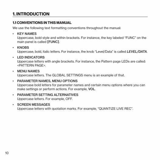
1.1 CONVENTIONS IN THIS MANUALWe use the following text formatting conventions throughout the manual:
• KEY NAMES Uppercase, bold style and within brackets. For instance, the key labeled “FUNC” on the main panel is called [FUNC].
• KNOBS Uppercase, bold, italic letters. For instance, the knob “Level/Data” is called LEVEL/DATA.
• LED INDICATORS Uppercase letters with angle brackets. For instance, the Pattern page LEDs are called: <PATTERN PAGE>.
• MENU NAMES Uppercase letters. The GLOBAL SETTINGS menu is an example of that.
• PARAMETER NAMES, MENU OPTIONS Uppercase bold letters for parameter names and certain menu options where you can make settings or perform actions. For example, VOL.
• PARAMETER SETTING ALTERNATIVES Uppercase letters. For example, OFF.
• SCREEN MESSAGES Uppercase letters with quotation marks. For example, “QUANTIZE LIVE REC”.
11
2. PANEL LAYOUT AND CONNECTIONS
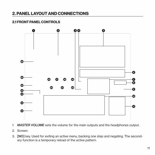
2.1 FRONT PANEL CONTROLS
Polyphonic Digital Synthesizer
Digitone
12
13
23
24
14
15
6
521
25
20 21 22
19181716 7
9
8
11
10
3 4
1. MASTER VOLUME sets the volume for the main outputs and the headphones output.
2. Screen.
3. [NO] key. Used for exiting an active menu, backing one step and negating. The second-ary function is a temporary reload of the active pattern.
12
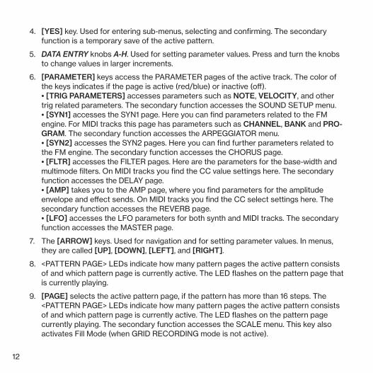
4. [YES] key. Used for entering sub-menus, selecting and confirming. The secondary function is a temporary save of the active pattern.
5. DATA ENTRY knobs A-H. Used for setting parameter values. Press and turn the knobs to change values in larger increments.
6. [PARAMETER] keys access the PARAMETER pages of the active track. The color of the keys indicates if the page is active (red/blue) or inactive (off). • [TRIG PARAMETERS] accesses parameters such as NOTE, VELOCITY, and other trig related parameters. The secondary function accesses the SOUND SETUP menu. • [SYN1] accesses the SYN1 page. Here you can find parameters related to the FM engine. For MIDI tracks this page has parameters such as CHANNEL, BANK and PRO-GRAM. The secondary function accesses the ARPEGGIATOR menu. • [SYN2] accesses the SYN2 pages. Here you can find further parameters related to the FM engine. The secondary function accesses the CHORUS page. • [FLTR] accesses the FILTER pages. Here are the parameters for the base-width and multimode filters. On MIDI tracks you find the CC value settings here. The secondary function accesses the DELAY page. • [AMP] takes you to the AMP page, where you find parameters for the amplitude envelope and effect sends. On MIDI tracks you find the CC select settings here. The secondary function accesses the REVERB page. • [LFO] accesses the LFO parameters for both synth and MIDI tracks. The secondary function accesses the MASTER page.
7. The [ARROW] keys. Used for navigation and for setting parameter values. In menus, they are called [UP], [DOWN], [LEFT], and [RIGHT].
8. <PATTERN PAGE> LEDs indicate how many pattern pages the active pattern consists of and which pattern page is currently active. The LED flashes on the pattern page that is currently playing.
9. [PAGE] selects the active pattern page, if the pattern has more than 16 steps. The <PATTERN PAGE> LEDs indicate how many pattern pages the active pattern consists of and which pattern page is currently active. The LED flashes on the pattern page currently playing. The secondary function accesses the SCALE menu. This key also activates Fill Mode (when GRID RECORDING mode is not active).
13
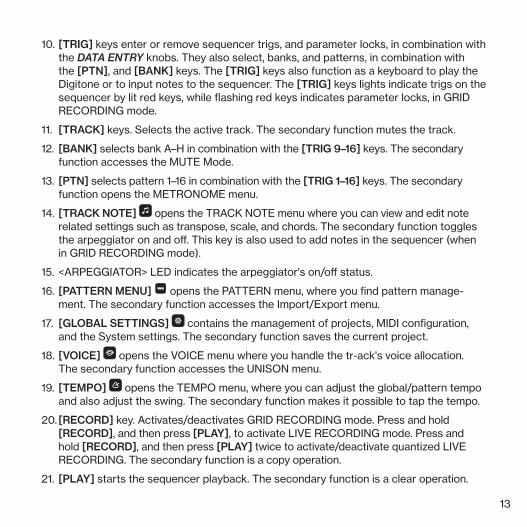
10. [TRIG] keys enter or remove sequencer trigs, and parameter locks, in combination with the DATA ENTRY knobs. They also select, banks, and patterns, in combination with the [PTN], and [BANK] keys. The [TRIG] keys also function as a keyboard to play the Digitone or to input notes to the sequencer. The [TRIG] keys lights indicate trigs on the sequencer by lit red keys, while flashing red keys indicates parameter locks, in GRID RECORDING mode.
11. [TRACK] keys. Selects the active track. The secondary function mutes the track.
12. [BANK] selects bank A–H in combination with the [TRIG 9–16] keys. The secondary function accesses the MUTE Mode.
13. [PTN] selects pattern 1–16 in combination with the [TRIG 1–16] keys. The secondary function opens the METRONOME menu.
14. [TRACK NOTE] opens the TRACK NOTE menu where you can view and edit note related settings such as transpose, scale, and chords. The secondary function toggles the arpeggiator on and off. This key is also used to add notes in the sequencer (when in GRID RECORDING mode).
15. <ARPEGGIATOR> LED indicates the arpeggiator's on/off status.
16. [PATTERN MENU] opens the PATTERN menu, where you find pattern manage-ment. The secondary function accesses the Import/Export menu.
17. [GLOBAL SETTINGS] contains the management of projects, MIDI configuration, and the System settings. The secondary function saves the current project.
18. [VOICE] opens the VOICE menu where you handle the tr-ack's voice allocation. The secondary function accesses the UNISON menu.
19. [TEMPO] opens the TEMPO menu, where you can adjust the global/pattern tempo and also adjust the swing. The secondary function makes it possible to tap the tempo.
20. [RECORD] key. Activates/deactivates GRID RECORDING mode. Press and hold [RECORD], and then press [PLAY], to activate LIVE RECORDING mode. Press and hold [RECORD], and then press [PLAY] twice to activate/deactivate quantized LIVE RECORDING. The secondary function is a copy operation.
21. [PLAY] starts the sequencer playback. The secondary function is a clear operation.

14
22. [STOP] stops playback. The secondary function is a paste operation.
23. [MIDI] activates the MIDI editing mode where you can edit the MIDI tracks. A lit [MIDI] key indicates the MIDI editing mode is active. The secondary function opens the MIDI CONFIG menu.
24. [FUNC] key. Press and hold [FUNC], and then press another key to access the sec-ondary function of that key. The blue-green text on the Digitone front panel shows the keys secondary functions.
25. LEVEL/DATA sets the overall volume level of the active track. You can also set param-eters and scroll through lists. The secondary function opens the SOUND BROWSER.
2.2 REAR PANEL CONNECTIONS
1 2 3 4 5 6 87 9
1. POWER Switch for turning the unit on and off.
2. DC In, Input for power supply. Use the included PSU-3b power adapter, connected to a power outlet.
3. USB For connecting the unit to a computer. For MIDI-control or Overbridge use. Use the included A to B USB 2.0 connector cable to connect to a computer host.
4. MIDI THRU/SYNC B Forwards data from MIDI IN. Can also be configured to send DIN sync to legacy instruments. Use a standard MIDI cable to connect another MIDI device in the chain.
15
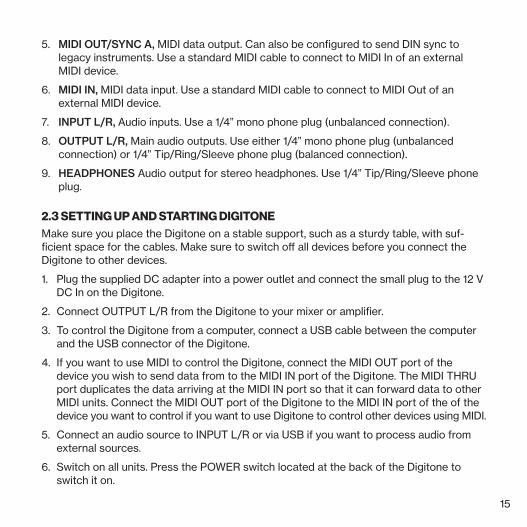
5. MIDI OUT/SYNC A, MIDI data output. Can also be configured to send DIN sync to legacy instruments. Use a standard MIDI cable to connect to MIDI In of an external MIDI device.
6. MIDI IN, MIDI data input. Use a standard MIDI cable to connect to MIDI Out of an external MIDI device.
7. INPUT L/R, Audio inputs. Use a 1/4” mono phone plug (unbalanced connection).
8. OUTPUT L/R, Main audio outputs. Use either 1/4” mono phone plug (unbalanced connection) or 1/4” Tip/Ring/Sleeve phone plug (balanced connection).
9. HEADPHONES Audio output for stereo headphones. Use 1/4” Tip/Ring/Sleeve phone plug.
2.3 SETTING UP AND STARTING DIGITONEMake sure you place the Digitone on a stable support, such as a sturdy table, with suf-ficient space for the cables. Make sure to switch off all devices before you connect the Digitone to other devices.
1. Plug the supplied DC adapter into a power outlet and connect the small plug to the 12 V DC In on the Digitone.
2. Connect OUTPUT L/R from the Digitone to your mixer or amplifier.
3. To control the Digitone from a computer, connect a USB cable between the computer and the USB connector of the Digitone.
4. If you want to use MIDI to control the Digitone, connect the MIDI OUT port of the device you wish to send data from to the MIDI IN port of the Digitone. The MIDI THRU port duplicates the data arriving at the MIDI IN port so that it can forward data to other MIDI units. Connect the MIDI OUT port of the Digitone to the MIDI IN port of the of the device you want to control if you want to use Digitone to control other devices using MIDI.
5. Connect an audio source to INPUT L/R or via USB if you want to process audio from external sources.
6. Switch on all units. Press the POWER switch located at the back of the Digitone to switch it on.
16
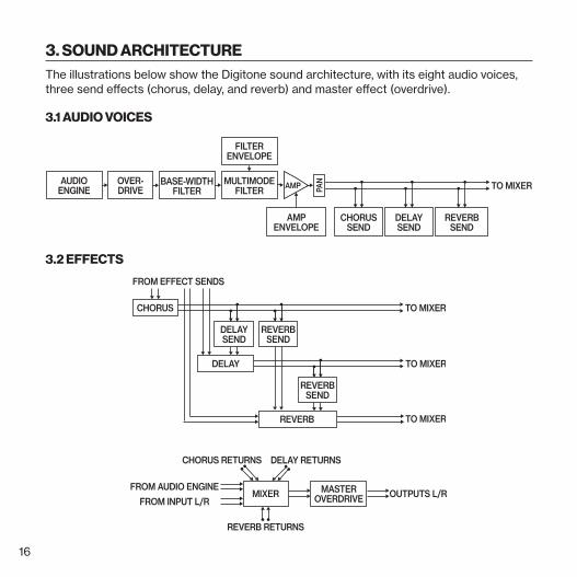
3. SOUND ARCHITECTUREThe illustrations below show the Digitone sound architecture, with its eight audio voices, three send effects (chorus, delay, and reverb) and master effect (overdrive).
3.1 AUDIO VOICES
AUDIOENGINE
OVER-DRIVE
MULTIMODEFILTER AMPBASE-WIDTH
FILTER
FILTERENVELOPE
AMPENVELOPE
MIXER
DELAY RETURNS
FROM AUDIO ENGINEOUTPUTS L/R
FADEENVELOPE
LFO DESTINATION
PAN
DELAYSEND
REVERBSEND
TO MIXER
DELAYSEND
CHORUS
DELAY
FROM EFFECT SENDS
TO MIXER
TO MIXER
REVERB RETURNS
CHORUSSEND
FROM INPUT L/RMASTER
OVERDRIVE
CHORUS RETURNS
REVERBSEND
REVERBSEND
REVERB TO MIXER
3.2 EFFECTS
AUDIOENGINE
OVER-DRIVE
MULTIMODEFILTER AMPBASE-WIDTH
FILTER
FILTERENVELOPE
AMPENVELOPE
MIXER
DELAY RETURNS
FROM AUDIO ENGINEOUTPUTS L/R
FADEENVELOPE
LFO DESTINATION
PAN
DELAYSEND
REVERBSEND
TO MIXER
DELAYSEND
CHORUS
DELAY
FROM EFFECT SENDS
TO MIXER
TO MIXER
REVERB RETURNS
CHORUSSEND
FROM INPUT L/RMASTER
OVERDRIVE
CHORUS RETURNS
REVERBSEND
REVERBSEND
REVERB TO MIXER
AUDIOENGINE
OVER-DRIVE
MULTIMODEFILTER AMPBASE-WIDTH
FILTER
FILTERENVELOPE
AMPENVELOPE
MIXER
DELAY RETURNS
FROM AUDIO ENGINEOUTPUTS L/R
FADEENVELOPE
LFO DESTINATIONPA
N
DELAYSEND
REVERBSEND
TO MIXER
DELAYSEND
CHORUS
DELAY
FROM EFFECT SENDS
TO MIXER
TO MIXER
REVERB RETURNS
CHORUSSEND
FROM INPUT L/RMASTER
OVERDRIVE
CHORUS RETURNS
REVERBSEND
REVERBSEND
REVERB TO MIXER
17
4. THE USER INTERFACE
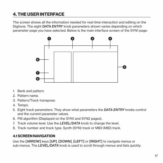
The screen shows all the information needed for real-time interaction and editing on the Digitone. The eight DATA ENTRY knob parameters shown varies depending on which parameter page you have selected. Below is the main interface screen of the SYN1 page.
1 2 4
5
7
6
8
3
1. Bank and pattern.2. Pattern name.3. Pattern/Track transpose.4. Tempo.5. Eight track parameters. They show what parameters the DATA ENTRY knobs control
and the current parameter values. 6. FM algorithm (Displayed on the SYN1 and SYN2 pages).7. Track volume level. Use the LEVEL/DATA knob to change the level.8. Track number and track type. Synth (SYN) track or MIDI (MID) track.
4.1 SCREEN NAVIGATIONUse the [ARROW] keys [UP], [DOWN], [LEFT] or [RIGHT] to navigate menus or sub-menus. The LEVEL/DATA knob is used to scroll through menus and lists quickly.
18
[YES] is used to affirm, select, enter sub-menus and tick/untick boxes.
[NO] is used to negate, deselect or go back one or more steps.
4.2 PARAMETER EDITINGThe DATA ENTRY knobs are used to change the values of the track parameters. The po-sitions of the parameters on the screen correspond to the physical locations of the knobs on the front panel.
• The parameters are adjusted in larger increments if you press down the DATA ENTRY knob while turning it. This function makes it quicker to sweep through the whole param-eter range.
• Press DATA ENTRY knob + [NO] to reset the parameter to the default value.
• Press [PARAMETER] + [FUNC] + [PLAY] to reset all the parameters on the selected parameter page to default values.
• Press and hold a [PARAMETER] key to see the exact values of the parameters.
4.3 PARAMETER VALUE JUMPPressing [FUNC] while editing certain parameters makes the parameter values jump to appropriate positions. The time of the Delay, for example, doubles and halves the value.
4.4 [FUNC] KEY PRESS COMBINATIONSThe standard way to use the [FUNC] key in combination with other keys, is to press and hold [FUNC] and then press the second key in the combination. For some key combina-tions, it is also possible to access a sub-menu by pressing and holding [FUNC] + second key for a second.
4.5 QUICK SCROLLINGScroll through menus using the LEVEL/DATA knob. Quick scrolling is possible on many menus. Press [FUNC] + the [UP] or [DOWN] keys to move the cursor one menu page.
19
4.6 COPY, CLEAR AND PASTECopy, clear and paste commands are available in many contexts. Pressing [FUNC] + [REC] to copy. Press [FUNC] + [STOP] to paste. Press [FUNC] + [PLAY] to clear. Repeat the key press combination to undo the paste and clear operations. See the different sections in the Digitone User Manual for more information on when these commands are available.
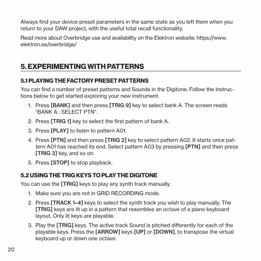
4.7 THE NAMING SCREENThe naming method is identical for the various naming situations that appear when you save sounds, projects et cetera.
The [LEFT] and [RIGHT] arrow keys are used to navigate between the characters. Turning the LEVEL/DATA knob or pressing the [UP] or [DOWN] arrow keys selects the characters. [FUNC] + [NO] erases letters. Press and hold [FUNC] to access the pop-up naming menu.
4.8 OVERBRIDGEThe Overbridge software suite enables a tight integration between the Digitone and a computer DAW software.
When using Overbridge, the user interface for the Digitone presents itself as a plug-in window in your DAW. Access, edit and automate parameters for sound shaping on screen.
20
Always find your device preset parameters in the same state as you left them when you return to your DAW project, with the useful total recall functionality.
Read more about Overbridge use and availability on the Elektron website: https://www.elektron.se/overbridge/
5. EXPERIMENTING WITH PATTERNS
5.1 PLAYING THE FACTORY PRESET PATTERNSYou can find a number of preset patterns and Sounds in the Digitone. Follow the instruc-tions below to get started exploring your new instrument.
1. Press [BANK] and then press [TRIG 9] key to select bank A. The screen reads “BANK A : SELECT PTN”.
2. Press [TRIG 1] key to select the first pattern of bank A.
3. Press [PLAY] to listen to pattern A01.
4. Press [PTN] and then press [TRIG 2] key to select pattern A02. It starts once pat-tern A01 has reached its end. Select pattern A03 by pressing [PTN] and then press [TRIG 3] key, and so on.
5. Press [STOP] to stop playback.
5.2 USING THE TRIG KEYS TO PLAY THE DIGITONEYou can use the [TRIG] keys to play any synth track manually.
1. Make sure you are not in GRID RECORDING mode.
2. Press [TRACK 1–4] keys to select the synth track you wish to play manually. The [TRIG] keys are lit up in a pattern that resembles an octave of a piano keyboard layout. Only lit keys are playable.
3. Play the [TRIG] keys. The active track Sound is pitched differently for each of the playable keys. Press the [ARROW] keys [UP] or [DOWN], to transpose the virtual keyboard up or down one octave.
21
5.3 USING MUTE MODEYou can mute/unmute any of the sequencer tracks in this mode. You can mute/unmute all tracks simultaneously.
1. Make sure a pattern is playing.
2. Press [FUNC] + [BANK] to enter MUTE mode.
3. Press any of the [TRACK] keys to mute the corresponding track. Press again to unmute. The color of the [TRACK] keys indicates the mute status. Unlit keys are muted tracks. Green keys are active tracks.
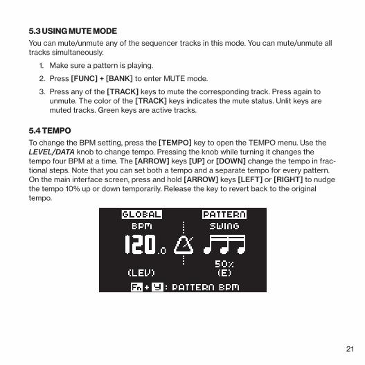
5.4 TEMPOTo change the BPM setting, press the [TEMPO] key to open the TEMPO menu. Use the LEVEL/DATA knob to change tempo. Pressing the knob while turning it changes the tempo four BPM at a time. The [ARROW] keys [UP] or [DOWN] change the tempo in frac-tional steps. Note that you can set both a tempo and a separate tempo for every pattern. On the main interface screen, press and hold [ARROW] keys [LEFT] or [RIGHT] to nudge the tempo 10% up or down temporarily. Release the key to revert back to the original tempo.

22
6. ABOUT THE TRACKS
6.1 THE SYNTH TRACKSThe Digitone has four synth tracks. Each synth track holds one Sound. The Sound con-tains the settings in the PARAMETER pages (SYN1, SYN2, FLTR, AMP, and LFO) together with the settings in the SOUND SETTINGS menu and the ARPEGGIATOR menu.
To select a synth track to edit, press one of the [TRACK 1–4] keys.
6.2 THE MIDI TRACKSThe Digitone also has four dedicated MIDI tracks. The MIDI tracks are used to control external MIDI-equipped gear. Each MIDI track can trigger a chord of up to 8 notes with adjustable parameters such as velocity and length, control pitch bend and aftertouch as well as 8 freely assignable MIDI control change parameters (MIDI CCs). The MIDI tracks function almost the same way as the synth tracks, with features such as parameter locks, LFO modulation, micro timing, trig conditions, individual track length and time signature settings.
To select a MIDI track to edit, press and hold [MIDI] key and then press one of the [TRACK 1–4] keys.
6.3 EDITING THE TRACKSThe six [PARAMETER] keys open parameter pages that you use to edit the tracks and Sounds. The TRIG, SYN2, FLTR, AMP, and LFO parameter groups has two pages To access page one, press the [PARAMETER] key once. To access page two, press the [PARAMETER] key twice. The TRIG pages contains different parameters such as NOTE, VELOCITY, and other trig related parameters. The parameters on the SYN1 and SYN2 pages controls various aspects of the FM synthesis. For MIDI tracks the SYN1 page has parameters such as CHANNEL, PROGRAM, and AFTERTOUCH. On the FLTR page, you find parameters for the multimode and base-width filters and the filter envelope for the synth tracks. For MIDI tracks you find the CC value settings here. The AMP page for synth tracks hosts parameters for the amplitude envelope and effect sends. For MIDI tracks you find the CC select settings here. Finally, the LFO page hosts the LFO parameters for the active track. Use the DATA ENTRY knobs A-H to edit the corresponding parameters.

23
7. THE SEQUENCERThe Digitone's sequencer stores its information in patterns. A pattern controls the play-back of the synth tracks and the MIDI tracks by the trigs entered on the sequencer.
7.1 SELECTING A PATTERN1. Press [BANK] + [TRIG 9–16] key to select bank A–H.
2. Press [TRIG 1–16] key to select pattern 1–16. (Press [PTN] + [TRIG 1–16] if you want to change pattern without changing bank.)
White [TRIG] keys indicate pattern positions that contain data. A red [TRIG] key indicates the current active pattern. Empty patterns [TRIG] keys are unlit.
7.2 PATTERN CONTROLPress [PLAY] to start the pattern playback. Press [PLAY] again to pause. Press [STOP] to stop the playback. The audio is cut off, but effects like the delay continues until the delay repeats fades out. Quickly press [STOP] twice to stop playback of all tracks and the fade out of the send effects.
If you change patterns during playback, the patterns changes after the current playing pattern reaches its end.
7.3 TRIGS AND TRIG TYPESA trig is a sequencer event that you can place where you want the sequencer to perform an action on the Digitone. There are two types of trigs available in both recording modes: Note trigs and Lock trigs.
• Note trigs trigger notes on synth tracks and MIDI tracks.
• Lock trigs trigger parameter locks, but without triggering notes.
7.4 PATTERN RECORDING MODESThe Digitone offers two main modes of inputting trigs when you create a pattern: GRID RECORDING mode and LIVE RECORDING mode. To create a new pattern first select an empty pattern slot in one of the banks.
24
7.5 GRID RECORDING MODEGRID RECORDING is a method of composing where you use the [TRIG] keys to add trigs in the pattern grid.
1. Press [TRACK 1–4] to select the track to which you want to add trigs. A green [TRACK] key light indicates the active track.
2. Press [RECORD] to enter GRID RECORDING mode. The [RECORD] key lights up red to indicate that GRID RECORDING mode is active.
3. Use the [TRIG] keys to place note trigs on the sequencer. The trigs note value is the value specified by the NOTE parameter in the TRIG PARAMETERS page. To add a lock trig, press [FUNCTION] and [TRIG]. You can enter lock trigs on any sequencer step, including ones that contain note trigs. Press the [TRIG] key of any of the pre-viously entered trigs if you wish to remove the trig. Press a [TRIG] key of a trig and hold it slightly longer to prepare the trig for editing, rather than removing it.
4. Select another track, and add note trigs and lock trigs. Repeat the procedure for all the tracks you want to use.
5. Press [PLAY] to listen to the sequence.
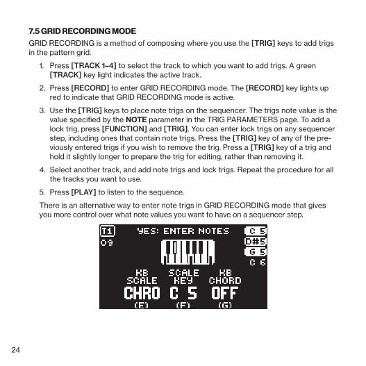
There is an alternative way to enter note trigs in GRID RECORDING mode that gives you more control over what note values you want to have on a sequencer step.
25
1. Press [TRACK 1–4] to select the track to which you want to add note trigs and addi-tional notes. A green [TRACK] key light indicates the active track.
2. Press [RECORD] to enter GRID RECORDING mode. The [RECORD] key lights up red to indicate that GRID RECORDING mode is active.
3. Press the [TRIG] key to where you want to add or remove notes + [TRACK NOTE] . A graphic keyboard appears on the screen where you can see all the notes on
the chosen sequencer step. A highlighted key on the screen keyboard indicates the notes added to the trig.
4. Press the [TRIG] keys to add notes with the corresponding note value. Press the [TRIG] key of a previously entered note if you wish to remove that note.
5. Press [YES] to enter the changes and then exit. Press [NO] if you wish to exit with-out making any changes.
Press [RECORD] to exit GRID RECORDING mode.
7.7 LIVE RECORDING MODELIVE RECORDING mode is the second method of adding trigs to the tracks. In this record-ing mode, all the [TRIG] keys are played in real time to input trigs to the tracks. You can also turn the DATA ENTRY knobs to enter lock trigs with parameter locks in real time.
1. Press and hold [RECORD], then press [PLAY] to enter LIVE RECORDING mode. If you quickly press [PLAY] twice while keeping the [RECORD] key pressed, you activate/deactivate the quantization of LIVE RECORDING. The sequencer starts to play, and the [RECORD] key starts to flash red.
2. Press the [TRIG] keys and turn the DATA ENTRY knobs to enter trigs in real time. The [TRIG] key pressed determines the pitch value of the note trig.
3. Press [PLAY] to exit LIVE RECORDING mode while keeping the sequencer playing. GRID RECORDING mode is activated if you press [RECORD] while LIVE RECORD-ING mode is active.
4. Press [STOP] to stop both recording and playback of the sequencer.

26
7.8 PARAMETER LOCKSParameter locks enable all trigs to have their unique parameter values. The note trigs of a synth track can, for example, have different pitch, velocity or length settings. It is possible to parameter lock all parameters found on the PARAMETER pages, and you can apply parameter locks on both synth and MIDI tracks.
In GRID RECORDING mode, press [FUNC] + [TRIG] to add a lock trig. On a lock trig, you can add parameter changes without trigging a note. A yellow [TRIG] key indicates that it has a lock trig. Then press and hold the [TRIG] key of a trig and use the DATA ENTRY knobs adjust the parameters to which you want to add parameter locks. The graphics on the screen becomes inverted for the locked parameter and shows the locked parameter value. The [TRIG] key of the locked trig begins to flash, to indicate that the trig now con-tains a parameter lock.
Press and hold [TRIG] and then press the DATA ENTRY knob of the locked parameter to remove a single parameter lock. All parameter locks are erased from the trig if you remove a note trig and then enter it again.
In LIVE RECORDING mode, turn the DATA ENTRY knobs, or play the [TRIG] keys to add parameter locks to the active track. Note trigs are placed, and parameter locked accord-ingly, and it also places lock trigs that contain the parameter locks on the sequencer steps that do not already have any trigs.
7.9 PATTERN SCALEYou can change the length and timing of the pattern.
1. Press [FUNC] + [PAGE] to access the scale menu.
2. Use the DATA ENTRY knobs to change the settings.
The left figure under LENGTH shows the number of steps in the pattern. The total length, shown on the right, determines the maximum number of steps. The figure under SCALE displays the time signature of the pattern. If you use 17 steps or more in a pattern, the [PAGE] key can toggle between the different pattern pages when in GRID RECORDING mode.

27
7.10 PATTERN SWINGAdjust the swing setting of the pattern, to employ a propulsive, rhythmic groove.
1. Press [TEMPO] to access the tempo/swing menu.
2. Turn DATA ENTRY knob E to set the SWING ratio from 50% to 80%. The default setting is equal spacing, 50%.
8. THE DIGITONE FM SYNTHESIS
8.1 OVERVIEWAt its core, the Digitone is a standard four operator FM synth in the style of the classic 80s implementations. However, unlike the early FM synths, the Digitone use its FM engine more like a complex tone generator than a complete synthesizer voice (although it does have this capability too). The Digitone signal path is much more similar to a typical sub-tractive synth rather than a classic FM voice.
FM Overdrive MultimodeFilter
Base-widthFilter
Amp
The idea of this design is to harness the raw, and sometimes complex, soundscapes of FM synthesis and use a more well-known and approachable subtractive method for the overall sound shaping.
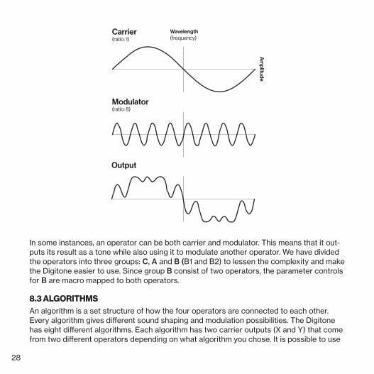
8.2 THE OPERATORSIn FM synthesis an operator basically functions as an oscillator. The difference is that an operator contains an envelope and specific input and outputs, making it a sort of mac-ro oscillator. FM combines two or more operators to generate a more harmonically rich output. An operator that is used to modulate another operator is called a modulator. The operator that generates the resulting tone is called a carrier.
28
Am
plitude
Wavelength(frequency)
Output
Modulator(ratio: 8)
Carrier(ratio: 1)
In some instances, an operator can be both carrier and modulator. This means that it out-puts its result as a tone while also using it to modulate another operator. We have divided the operators into three groups: C, A and B (B1 and B2) to lessen the complexity and make the Digitone easier to use. Since group B consist of two operators, the parameter controls for B are macro mapped to both operators.
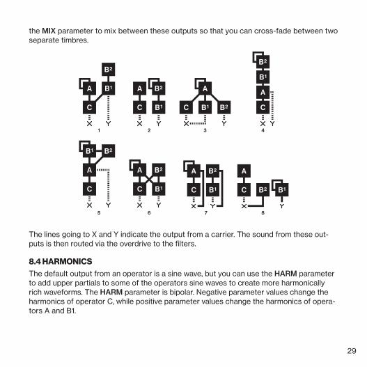
8.3 ALGORITHMSAn algorithm is a set structure of how the four operators are connected to each other. Every algorithm gives different sound shaping and modulation possibilities. The Digitone has eight different algorithms. Each algorithm has two carrier outputs (X and Y) that come from two different operators depending on what algorithm you chose. It is possible to use
29
the MIX parameter to mix between these outputs so that you can cross-fade between two separate timbres.
1 2 3 4
5 6 7 8
The lines going to X and Y indicate the output from a carrier. The sound from these out-puts is then routed via the overdrive to the filters.
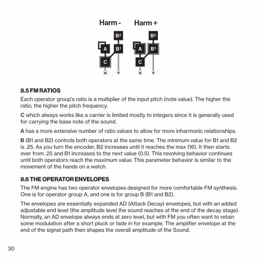
8.4 HARMONICSThe default output from an operator is a sine wave, but you can use the HARM parameter to add upper partials to some of the operators sine waves to create more harmonically rich waveforms. The HARM parameter is bipolar. Negative parameter values change the harmonics of operator C, while positive parameter values change the harmonics of opera-tors A and B1.
30
Harm - Harm +
8.5 FM RATIOSEach operator group's ratio is a multiplier of the input pitch (note value). The higher the ratio, the higher the pitch frequency.
C which always works like a carrier is limited mostly to integers since it is generally used for carrying the base note of the sound.
A has a more extensive number of ratio values to allow for more inharmonic relationships.
B (B1 and B2) controls both operators at the same time. The minimum value for B1 and B2 is .25. As you turn the encoder, B2 increases until it reaches the max (16). It then starts over from .25 and B1 increases to the next value (0.5). This revolving behavior continues until both operators reach the maximum value. This parameter behavior is similar to the movement of the hands on a watch.
8.6 THE OPERATOR ENVELOPESThe FM engine has two operator envelopes designed for more comfortable FM synthesis. One is for operator group A, and one is for group B (B1 and B2).
The envelopes are essentially expanded AD (Attack Decay) envelopes, but with an added adjustable end level (the amplitude level the sound reaches at the end of the decay stage). Normally, an AD envelope always ends at zero level, but with FM you often want to retain some modulation after a short pluck or fade in for example. The amplifier envelope at the end of the signal path then shapes the overall amplitude of the Sound.
31
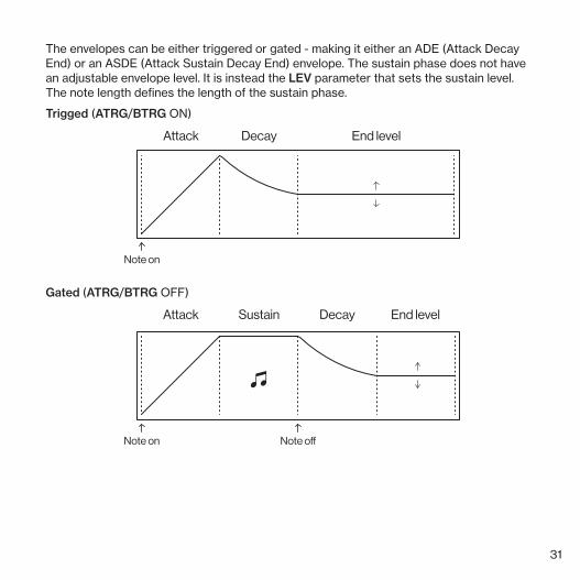
The envelopes can be either triggered or gated - making it either an ADE (Attack Decay End) or an ASDE (Attack Sustain Decay End) envelope. The sustain phase does not have an adjustable envelope level. It is instead the LEV parameter that sets the sustain level. The note length defines the length of the sustain phase.
Trigged (ATRG/BTRG ON)
Attack End levelDecay
Note on
Gated (ATRG/BTRG OFF)
Attack Decay End levelSustain
Note on Note o�

32
9. TECHNICAL INFORMATION
ELECTRICAL SPECIFICATIONSImpedance balanced audio outputs Main outputs level: +22 dBu Output impedance: 440 Ω unbalanced Digital-to-analog S/N ratio: 108 dB (20–20,000 Hz)
Headphones output Headphones out level: +22 dBu Output impedance: 55 Ω
Audio inputs Input level: +19 dBu Audio input impedance: 11 kΩ Analog-to-digital S/N ratio: 112 dB (20–20,000 Hz)
Unit power consumption: 7 W typical Compatible Elektron power supply: PSU-3b
HARDWARE128 × 64 pixel OLED screen MIDI In/Out/Thru with DIN Sync out 2 × 1/4” impedance balanced audio out jacks 2 × 1/4” audio in jacks 1 × 1/4” stereo headphone jack 48 kHz, 24-bit D/A and A/D converters Electrically isolated Hi-Speed USB 2.0 port Power inlet: Center positive 5.5 × 2.5 mm barrel jack, 12 V DC, 1 A
PHYSICAL SPECIFICATIONSSturdy steel casing Dimensions: W 215 × D176 × H 63 mm (8.5” × 6.9” × 2.5”) (including knobs and feet) Weight: approximately 1.49 kg (3.3 lbs) 100 × 100 mm VESA mounting holes. Use M4 screws with a max length of 7 mm. Maximum recommended ambient operating temperature: +40˚C (+104˚F)
33
10. CREDITS AND CONTACT INFORMATION
CREDITSPRODUCT DESIGN AND DEVELOPMENTOscar Albinsson Johannes Algelind Ali Alper Çakır Magnus Forsell Anders Gärder Andreas Henriksson Simon Mattisson Jimmy Myhrman Jon Mårtensson Viktor Nilsson Olle Petersson David Revelj Mattias Rickardsson Martin Sigby
ADDITIONAL DESIGNUfuk Demir Thomas Ekelund
DOCUMENTATION Erik Ångman
PRESET SOUND DESIGN Johannes Algelind Blush Response (Joey Gonzalez) Palle Dahlstedt Dataline (Cenk Sayınlı) Divkid (Ben Wilson)
Mark Fell Hizmi Toru Koda Simon Mattisson Jimmy Myhrman Zabutom (Niklas Sjösvärd) Erik Ångman
CONTACT INFORMATIONELEKTRON WEBSITEhttp://www.elektron.se
OFFICE ADDRESSElektron Music Machines MAV AB Sockerbruket 9 SE-414 51 Gothenburg Sweden
TELEPHONE+46 (0)31 743 744 0
34
INDEX
CCOPY, CLEAR AND PASTE 19
FFM SYNTHESIS 27
Algorithms 28Carrier 27FM ratios 30Harmonics 29Modulator 27Operator envelops 30Operators 27
FUNC KEY PRESS COMBINATIONS 18
NNAMING SCREEN 19
OOVERBRIDGE 19
PPANEL LAYOUT AND CONNECTIONS 11
Front panel controls 11Rear panel connections 14
PARAMETEREditing 18Parameter locks 26Value jump 18
PATTERNSExperimenting with patterns 20Mute mode 21Pattern scale 26
Pattern swing 27
RRECORDING MODES 23
Grid recording mode 24Live recording mode 25
SSAMPLING 27SCREEN NAVIGATION 17SEQUENCER 23
Grid recording mode 24Live recording mode 25Parameter locks 26Pattern control 23Pattern recording modes 23Pattern scale 26Pattern swing 27Selecting a pattern 23Trig types 23
SOUND ARCHITECTURE 16
TTECHNICAL INFORMATION 32TEMPO 21TRACKS 22
Audio tracks 22Editing 22MIDI tracks 22
TRIGSTrig types 23

2115
EN
G-A