masonry bunds ciria/environment for oil storage …bundlining.co.uk/downloads/ciria-ea guidelines...
TRANSCRIPT
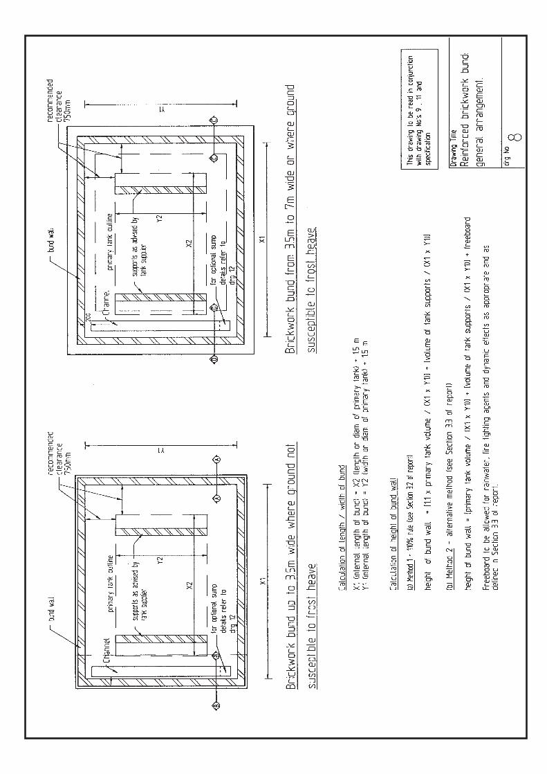
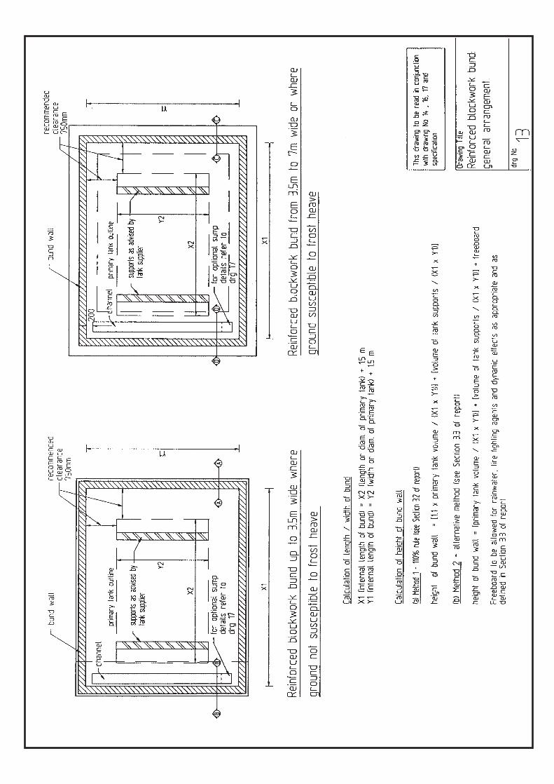
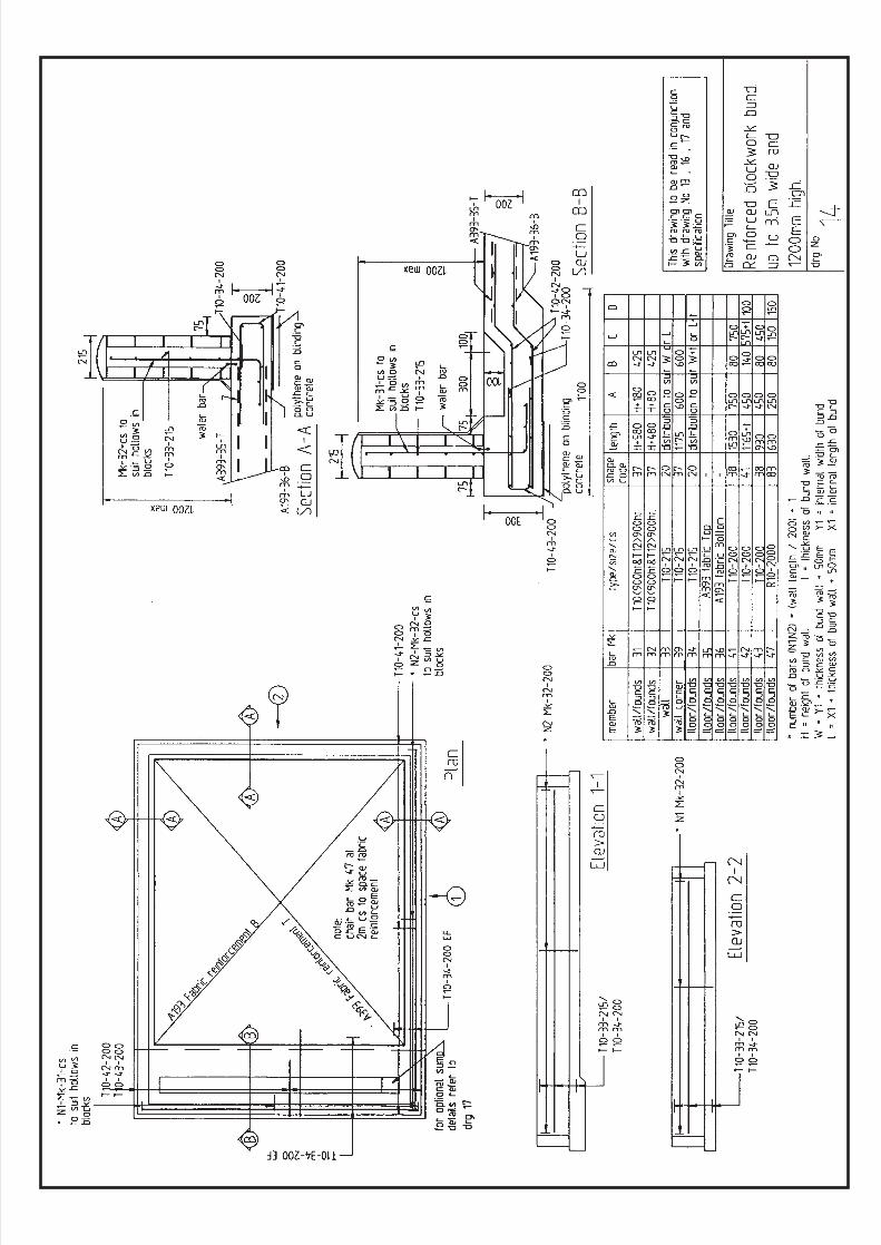
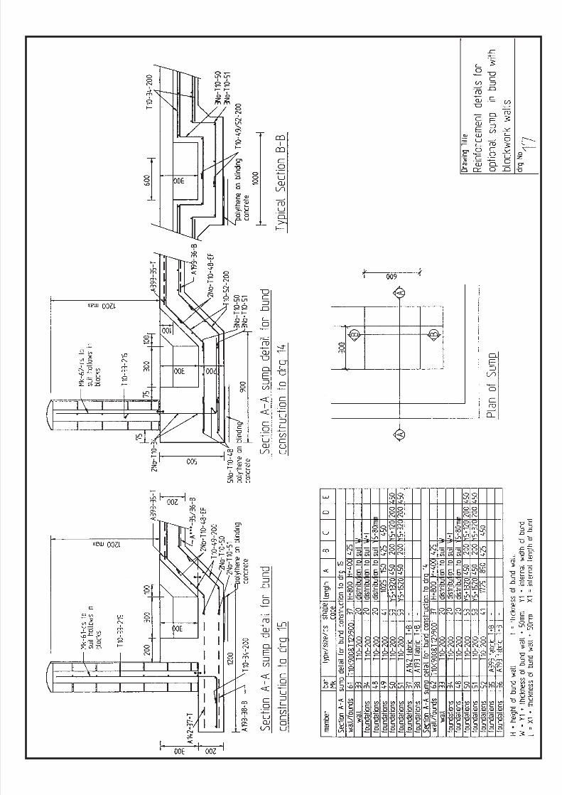
This document provides guidance for the construction of simple, reinforced masonry bunds for oil storagetanks up to 3.5 metres wide and 1200mm high. It is based upon CIRIA Report 163 “Construction of bunds
for oil storage tanks” and is jointly produced by the Environment Agency for England and Wales, the ScottishEnvironment Protection Agency and the Environment and Heritage Service for Northern Ireland, referred to asthe agencies. Where circumstances dictate a larger or more complex construction reference should be made
to the original report. A similar specification for concrete bunds is also available, free of charge, from theenvironment agencies. Contact details will be found at the end of this document.
Notes:To be read in conjunction with the enclosed construction drawings. The British Standards referred to in
these guidelines are listed in Appendix 1.
1. SITING AND SITE PREPARATION
a. Si te invest igat ionAvoid sites with:-variations in substrata which may give rise to differential settlementunstable slopes that may cause slip or other movementgeological faults, below ground voids or fissuresdeleterious matter present, which may have an adverse effect on constructionmaterialsa site history which may cause structural problems, e.g. previous mining, made-upground, underground services, etc.low ground bearing pressure (the model designs are based on a permissibleground bearing pressure of not less than 200kN/m2).
Note: the siting of a bund is dictated by the location of the primary tank, whichmay in turn be dictated by the general layout of the facility of which it is part. Itmay not be possible, therefore, to avoid sites with the characteristics listed above,in which case suitable precautions must be taken. The model drawings assumethat the proposed site does not have any of the undesirable features listed above.Where sites with any of the above undesirable features cannot be avoided,specialist advice should be sought.
b. Si te preparat ioni. Remove all vegetation and organic top soil from the site to expose the subsoil.
Suitable subsoils or substrata include:firm or stiff clayfirm or stiff sandy clayboulder clayshale clay (non sulphurous)compact sand or sandy gravelchalkrock.
ii. Excavate and trim the surface of the excavations to the level surfaces necessary forthe formation of wall foundations and the base slab.
CIRIA/ENVIRONMENTAGENCIES JOINTGUIDELINES
MASONRY BUNDSFOR OIL STORAGE
TANKS
If a larger or more complex construction is required, please refer to CIRIA Report 163 (see backpage for details)
iii. Soft ground should be excavated and removed, and the formation levelled downto firm ground with a permissible ground bearing pressure of not less than200kN/m2.
iv. Compact the excavated surfaces using a vibrating roller or vibrating platecompactor.
v. Protect the prepared formation from the elements prior to construction of base.
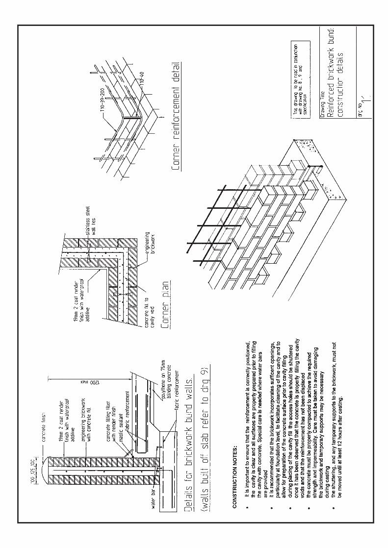
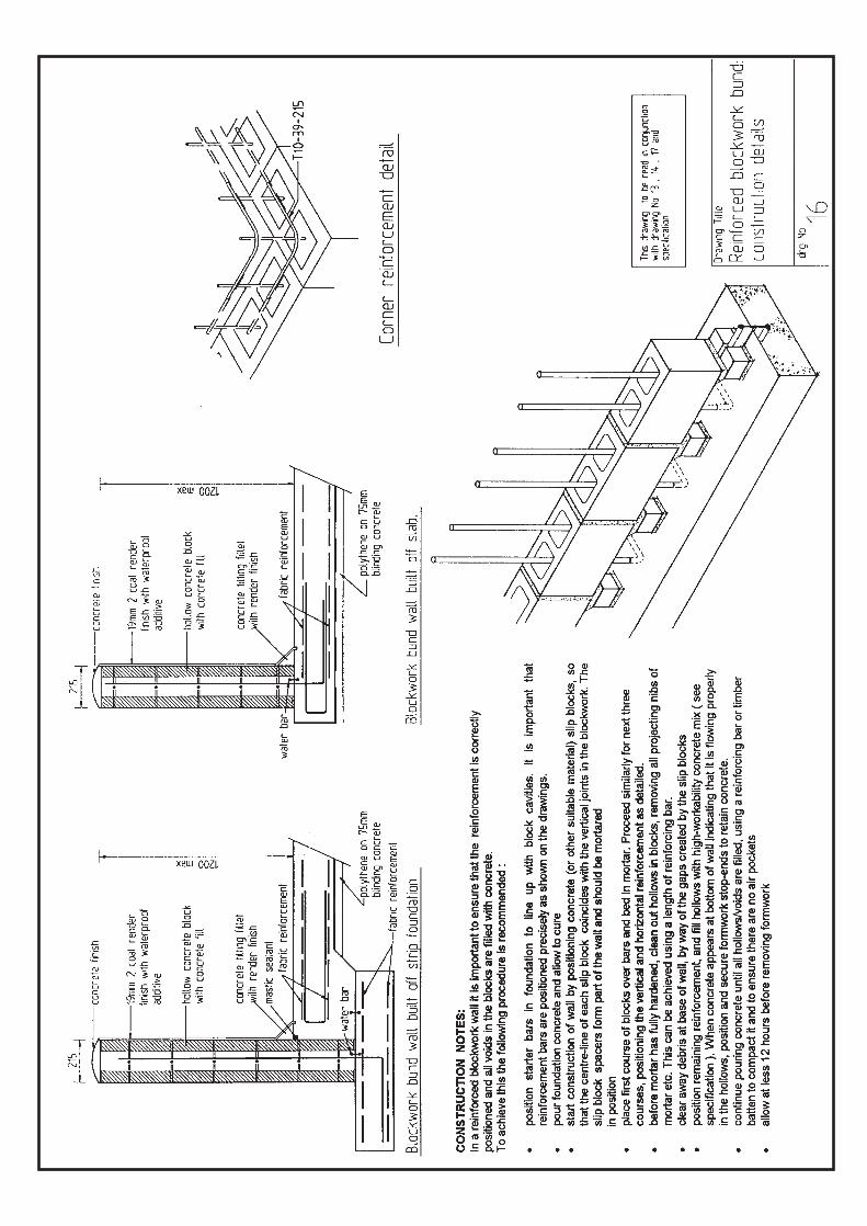
2. HARDCORE AND BLINDING CONCRETENote: Blinding concrete. The British Standard for water retaining structures, BS8007, requires that at least 75mm of C20 blinding concrete be placed directlyover the prepared formation. The structural concrete is then poured onto apolythene slip membrane placed on top of the blinding concrete.
In accordance with BS 8007, this specification requires ground level reinforcedconcrete slabs and wall foundations to be built on blinding concrete rather thanhardcore. Blinding concrete is also required for making up discrepancies in levelbetween the formation and the underside of the structure.
Hardcore should only be used for make up beneath the blinding concrete wherethe method of placing and compaction gives the hardcore sufficient strength tosupport the structure without any long-term adverse effect.
a. Where hardcore is to be used for making up levels, it should conform withGranular Sub Base Type 2, Table 8/3 of the Department of Transport Specification.The following gradation should be used:
BS sieve size Percentage by mass passing75mm 10037.5mm 85 -10010mm 45 - 1005mm 25 - 85600µm 8 - 4575µm 0 - 10
Suitable materials include natural sands, gravels, crushed rock and concrete. Thesoluble sulphate content should be within the DoT specified limits.
b. The hardcore should be placed in uniform horizontal layers not exceeding 150mmin depth. Each layer must be compacted prior to the placing of the next.
c. The compaction method should be sufficient to achieve the required permissiblebearing pressure of not less than 200kN/m2.
d. Suitable compaction plant includes vibrating rollers having a mass per metreequivalent to 1,300kg with a total weight of 1,000kg, and vibrating platecompactors having an equivalent mass of 1,000kg.
e. Granular fill in combination with geotextiles may be used to stabilise soft ground.Construction and design techniques are site-specific and expert advice should beobtained before using geotextiles.
3. REINFORCED MASONRY WALLS
a. Reinforced Blockwork to BS 5628i. Reinforced blockwork walls may be built off independent reinforced concrete strip
foundations or constructed integrally with the reinforced concrete bund floor.
If a larger or more complex construction is required, please refer to CIRIA Report 163 (see backpage for details)
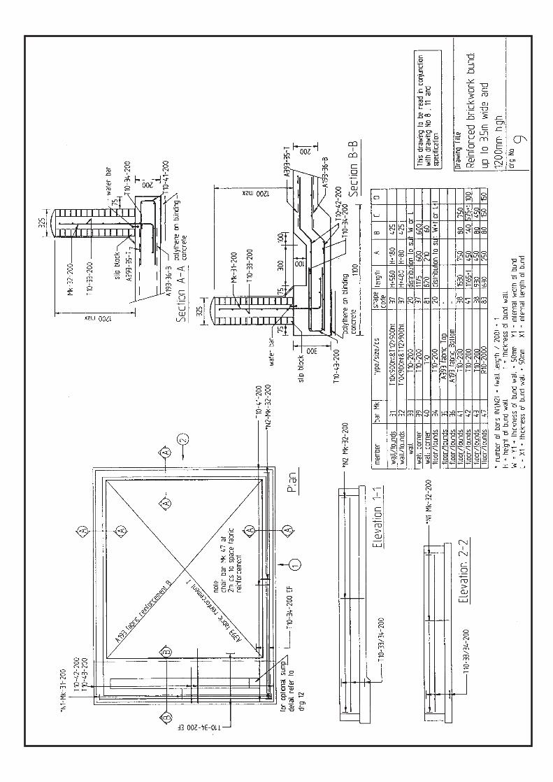
ii. In either case the ‘L’-shaped reinforcement bars, which give the blockwork itstensile strength, must be set in the correct positions before the foundation or slabis cast. Longitudinal lacer reinforcement bars are required to maintain thealignment of the ‘L’-shaped bars during concrete casting and, where appropriate,to tie the bottom leg of the bar to the mesh reinforcement of the foundations orslab.
iii. Hollow concrete blocks must comply with BS 6073. Block thickness must be notless than 215mm and net block strength should be not less than 10N/mm2.
iv. The mortar mix for bedding and jointing the blocks shall conform to BS 5628 class(i) and comprise the following proportions by volume:1 part of ordinary Portland cement, 1/4 part of hydrated lime, 3 parts sand.
v. The concrete for infilling the block cores shall be GEN 2 or a mix comprising thefollowing proportions measured by weight :1 part OPC, 3 parts sand to BS 882, 2 parts coarse aggregate to BS 882.The maximum size of the coarse aggregate shall be 10mm. The mix should havea high workability with a concrete slump of 150mm to 200mm. A superplasticisermay be used to help provide the necessary workability.
vi. The blocks must be laid and bonded so that the cores align vertically and that thecompleted work is in horizontal and vertical alignment and to the requireddimensions. ‘U’-shaped flat metal ties (one per core) may be used to bond theblock cavities at straight bonded pier positions.
vii. In order to facilitate proper placing of the infill concrete, the cores of the blocksand the reinforcement must be kept clean of any extraneous or adhered mortar.This can be achieved by placing the joints of the first row of blocks on smallconcrete block or brick spacers (see drawing no. 16).
viii. The vertical reinforcement should be fixed prior to laying the blocks.ix. Horizontal reinforcement must be placed as the work proceeds.x. On completion of the blockwork, the hollow cores should be cleaned out and,
when the mortar has hardened sufficiently, filled with concrete. When concretebegins to flow out of the bottom of the wall, the voids between the spacer blocksshould be shuttered. The infill concrete should be poured and tampedcontinuously until all core voids are filled. The cores should be slightly overfilledand the surplus concrete should be trowelled over to form a rounded copingalong the top of the wall.
xi. External surfaces and joints should be finished or prepared as necessary to becompatible with any subsequent surface coatings.
xii. The wall should not be fully loaded until it has achieved the specified 28-daydesign strength.
xiii. Wall Joints. It is extremely difficult to make watertight movement andconstruction joints in blockwork walls. Joints should therefore be avoidedwherever possible, although vertical movement joints are essential to helpminimise shrinkage cracking in long walls. Joint component and joint sealantmanufacturers should be consulted about suitable products and techniques forforming joints. Hydrostatic pressure limitations on wall joints may dictate themaximum wall height and therefore the bund capacity.Where a masonry wall would be so long (e.g. in multi-tank installations) that a verticalcontraction joint would be needed, it is recommended that either more than one bundis constructed (thus negating the need for joints), or that the bund is constructed fromreinforced concrete.
b. Reinforced Br ickwork to BS 5628
i. Reinforced brickwork, either concrete filled cavity or concrete pocket construction,may be founded on individual reinforced concrete strip footings or constructeddirectly off the reinforced concrete bund floor slab.
ii. In either case the specified wall reinforcement bars must be set into the concretefoundations and located at the correct positions to provide the reinforcement for
If a larger or more complex construction is required, please refer to CIRIA Report 163 (see backpage for details)
the walls. Lacer bars are necessary to maintain the position of the reinforcementbars during concrete casting (see 3aii). All wall reinforcement (includinghorizontal distribution bars in cavity fill construction) must be fixed prior toconstruction of the wall.
iii. Clay, solid class B engineering bricks to BS 3921 Table 1 and Table 6, (Class B) shallbe used for reinforced brickwork.
iv. Cavity brickwork should be of bonded stretchers, with the two skins tied togetherwith stainless steel wall ties.
v. 110mm thick walls and single skin blockwork shall be in stretcher bond: otherwalls shall be in English bond.
vi. The mortar mix must conform to BS 5628 class (i) and comprise the followingproportions by volume:1 part of OPC, 1/4 part of hydrated lime, 3 parts sand.
vii. The concrete for infilling cavity brickwork should be high workability grade RC30. viii. The mix for infilling blockwork cores shall be GEN2 or a mix comprising the
following proportions measured by weight:1 part OPC, 3 parts sand to BS 882, 2 parts coarse aggregate to BS 882.The maximum size of the coarse aggregate shall be 10mm. The mix should havea high workability with a concrete slump of 150mm to 200mm. A superplasticisermay be used to help achieve the necessary workability.
ix. Beds shall be level with joints of uniform thickness and perpends plumb. All bedsand joints should be flush and plumb. All bricks should be well wetted prior tolaying.
x. Brickwork should be true, square, and properly bonded and each course levelledround in a uniform manner.
xi. Reinforcement must be fixed in the correct position and all cavities and pocketskept free from all deleterious matter and extraneous mortar prior to concreteinfilling.
xii. Concrete infill should be uniformly placed and properly compacted in acontinuous operation taking care not to displace or damage the brickwork duringthis operation.
xiii. Internal surfaces of the walls should be prepared ready to receive any subsequentsurface coatings.
4. COATINGS AND SURFACE TREATMENTS
Masonry is inherently more permeable than in situ concrete. It is thereforerecommended that all internal masonry surfaces are rendered with at least 19 mmof sharp sand/OPC 3:1 mix applied in two coats. Surfaces should be properlyprepared and wetted prior to application. Special attention should be given to thejunction of the wall and floor slab. A mastic sealant is recommended at thejunction. Grooves should be cut in the concrete ready to receive the finishedcoatings. The second render coat should be applied so that joints in work areasdo not coincide with joints in the first coat.
Appendix 1 List of British Standards referred to in this specificationBS 8007:1987 Design of concrete structures for retaining aqueous liquidsBS 882: 1992 Specification for aggregates from natural sources for concreteBS 5628:Part 3: 1985 Use of masonryBS 6073:1981 Precast concrete masonry unitsBS 3921:1985 Clay bricks
If a larger or more complex construction is required, please refer to CIRIA Report 163 (see backpage for details)

For 40 years CIRIA - the Construction Industry Research and InformationAssociation - has managed collaborative research and produced informationaimed at providing best practice solutions to industry problems. CIRIA stimulatesthe exchange of experience across the industry and its clients, and has anestablished reputation for practical, high quality information. Through networkingand the dissemination of publications and newsletters, CIRIA seeks to improve theperformance of all concerned with construction and the environment.
For further information please contact CIRIA by:Post: 6, Storey’s Gate, Westminster, London SW1P 3AUTel: 020 7222 8891 (General Enquiries) 020 7799 3243 (Publications)Fax: 020 7222 1708e-mail: [email protected]
Further details are available on CIRIA’s Web site: www.ciria.org.uk
CIRIA Report 163 “Construction of bunds for oil storage tanks”ISBN 0 86017 468 9 Available from CIRIA, price £18
E M E R G E N C Y H O T L I N E
0800 80 70 60
The 24-hour emergency hotline number for reporting allenvironmental incidents relating to air, land and water inEngland, Wales, Scotland and Northern Ireland.
SCOTTISHENVIRONMENTPROTECTION AGENCY
REGIONAL OFFICES
ANGLIANKingfisher HouseGoldhay WayOrton GoldhayPeterborough PE2 5ZRTel: 01733 371 811Fax: 01733 231 840
MIDLANDSSapphire East550 Streetsbrook RoadSolihull B91 1QTTel: 0121 711 2324Fax: 0121 711 5824
NORTH EASTRivers House21 Park Square SouthLeeds LS1 2QGTel: 0113 244 0191Fax: 0113 246 1889
NORTH WESTRichard Fairclough HouseKnutsford RoadWarrington WA4 1HGTel: 01925 653 999Fax: 01925 415 961
HEAD OFFICEErskine CourtThe Castle Business ParkStirling FK9 4TRTel: 01786 457 700Fax: 01786 446 885World Wide Web: http: //www.sepa.org.uk
NORTH REGION HQGraesser HouseFodderty WayDingwall Business ParkDingwall IV15 9XBTel: 01349 862 021Fax: 01349 863 987
WEST REGION HQSEPA West5 Redwood CrescentPeel ParkEast Kilbride G74 5PPTel: 01355 574 200Fax: 01355 574 688
EAST REGION HQClearwater HouseHeriot-Watt Research ParkAvenue NorthRiccartonEdinburgh EH14 4APTel: 0131 449 7296Fax: 0131 449 7277
ENVIRONMENT AGENCY
REGIONAL OFFICES
HEAD OFFICERio House, Waterside Drive, Aztec WestAlmondsbury, Bristol BS32 4UD.Tel: 01454 624 400 Fax: 01454 624 409World Wide Web: http: //www.environment-agency.gov.uk
SOUTHERNGuildbourne HouseChatsworth RoadWorthingWest Sussex BN11 1LDTel: 01903 832 000Fax: 01903 821 832
SOUTH WESTManley HouseKestrel WayExeter EX2 7LQTel: 01392 444 000Fax: 01392 444 238
THAMESKings Meadow HouseKings Meadow RoadReading RG1 8DQTel: 0118 953 5000Fax: 0118 950 0388
WELSHRivers HouseSt Mellons Business ParkSt MellonsCardiff CF3 0EYTel: 029 2077 0088Fax: 029 2079 8555
All the Agencies’ pollution prevention guidance notes are available on the web sites listed below.
Printed on Cyclus TCF Recycled Paper. HO-3/00-10K-C-AYCJ
ENVIRONMENT &HERITAGE SERVICE
Calvert House,23 Castle Place,BelfastBT1 1FYTel: 028 9025 4868Fax: 028 9025 4777