mark iiia/iv/vlba tape formats, recording modes and ... · pdf file1 mark iiia/iv/vlba tape...
TRANSCRIPT

1
Mark IIIA/IV/VLBA Tape Formats, Recording Modes and Compatibility Revision 1.21
Alan R. Whitney MIT Haystack Observatory
10 June 2005 CONTENTS
1. INTRODUCTION 3 2. MARK IV TAPE FORMAT AND RECORDING MODES 3
2.1 Longitudinal Data Format 3 2.1.1 Time Code & CRC 3 2.1.2 Auxiliary Data Field 4 2.1.3 Sync Word 6 2.1.4 Data Field 6
2.2 Transverse Data Format 7 2.2.1 Data-Multiplexing 7 2.2.2 Data-Multiplex Track-Assignment and Barrel-Roll Conventions 8
2.3 Recorder Characteristics 8 2.3.1 Transport 9 2.3.2 Headstack 9 2.3.3 Headstack Positioner 10
2.4 Physical Recording-Format Conventions 10 2.4.1 Longitudinal 10 2.4.2 Transverse 10
3. VLBA TAPE FORMAT AND RECORDING MODES 10 3.1 Longitudinal Data Format 10
3.1.1 Time Code & CRC 11 3.1.2 Auxiliary Data 11 3.1.3 Sync Word 12 3.1.4 Data Field 12
3.2 Transverse Data Format 12 3.2.1 Barrel Roll Conventions 12 3.2.2 Cross Track Parity 14 3.2.3 Data-Multiplex (Fan-In/Fan-Out) Format 14
3.3 Recorder Characteristics 16 3.3.1 Transport 16 3.3.2 Headstack 16 3.3.3 Headstack Positioner 16
3.4 Physical Recording-Format Conventions 16 3.4.1 Longitudinal 16 3.4.2 Transverse 16
4. MARK IIIA TAPE FORMAT AND RECORDING MODES 16 4.1 Longitudinal Data Format 16
4.1.1 Time Code & CRC 17 4.1.2 Auxiliary Data 17 4.1.3 Sync Word 17 4.1.4 Data Field 17
4.2 Transverse Data Format 17 4.3 Recording Modes and Track Assignments 17 4.4 Recorder Characteristics 18
4.4.1 Tape Transport 18 4.4.2 Headstack 19 4.4.3 Headstack Positioner 19
2
4.5 Physical Recording-Format Conventions 19 4.5.1 Longitudinal 19 4.5.2 Transverse 19
5. STANDARD RECORDING MODES AND INTER-COMPATIBILITY 19 APPENDICES
Appendix A: Track numbering and aux-data track ID’s in Mark IIIA, Mark IV, VLBA 22 Appendix B: Tabular summary of primary Mark IIIA, Mark IV, VLBA characteristics 24 Appendix C: Document revision history 25 LIST OF TABLES
Table 1: Mark IV time-code definition 4 Table 2: Mark IV implied time code 4 Table 3: Mark IV sample-encoding definition 6 Table 4: Capabilities of Mark IV formatter 8 Table 5: Metrum model 96 transport characteristics 9 Table 6: Mark IIIA/Mark IV/VLBA headstack characteristics 9 Table 7: ‘Inchworm’ headstack-positioner characteristics 10 Table 8: Standard VLBA 16-track barrel-roll sequence 14 Table 9: Standard VLBA 16-track barrel-roll sequence for even tracks 14 Table 10: Track assignment for 1:4 fanout with 2-bit sampling 14 Table 11: Track assignment for 1:4 fanout with 1-bit sampling 14 Table 12: Track assignment for 1:2 fanout with 2-bit sampling 15 Table 13: Track assignment for 1:2 fanout with 1-bit sampling 15 Table 14: Track assignment for 1:1 fanout with 2-bit sampling 15 Table 15: Mark IIIA data-recording modes and Track assignments 18 Table 16: Standard Mark IV continuum modes and compatibility with VLBA and Mark IIIA 20 Table 17: Standard Mark IV spectroscopic modes and compatibility with VLBA and Mark IIIA 21 Table 18: Correspondence of Track numbers and aux-data Track-ID field in various systems 23 Table 19: Comparison of Mark IIIA, Mark IV and VLBA major characteristics 24
LIST OF FIGURES
Figure 1: Mark IV tape frame format 26 Figure 2: VLBA tape frame format 27 Figure 3: VLBA formatter and recorder signal paths 28 Figure 4: VLBA track layout on tape for 14-pass operation 29 Figure 5: Mark IIIA Mode A standard layout on tape 30 Figure 6: Mark IIIA Mode B,C standard layout on tape 31

3
1. Introduction
The Mark IIIA, VLBA and Mark IV VLBI data-acquisition systems are all based on the Metrum (formerly Honeywell) Model 96 transport using 1” wide reel-to-reel tape. Although the data-format on tape is very similar among these systems, there are significant differences in details that must be noted in order to successfully process data from these systems. The purpose of this memo is describe the tape and data formats of each of these systems in significant detail.
2. Mark IV Tape Format and Recording Modes
The Mark IV VLBI Data-Acquisition System is an upgrade to the original Mark IIIA system that was designed primarily for two purposes, 1) expansion of maximum data rate from 224 Mbits/sec to 1024 Mbits/sec and 2) full compatibility with all VLBA channel-bandwidth and data-multiplex modes. For this purpose, an entirely new formatter was designed for the Mark IV system, and modifications were made to BBC’s and the tape transport.
The Mark IV system can record up to 64 simultaneous tracks (expandable to 128 tracks) at a maximum date rate of 16 Mbits/sec/track (18 Mbits/sec/track with parity) for maximum total data rate of 1024 Mbits/sec (expandable to 2048 Mbits/sec). The data along each track is physically continuous, but are divided into logical frames, each frame being a self-contained unit containing synchronization, timing and auxiliary information as well as sampled data. In the Mark IV system, as in the VLBA system (but unlike the Mark IIIA system), data from a single video-converter (baseband-converter) channel may be distributed to multiple tracks; conversely, data from several channels may also be multiplexed onto a single track. Therefore, in order to completely understand the Mark IV tape format, we must understand both the format along a single track (longitudinal track format) and the format laterally across the simultaneously-written tracks (transverse track format). These are described in Sections 2.1 and 2.2, respectively.
2.1 Longitudinal Data Format
The continuous stream of bits along each single track is logically divided into Tape Frames. Each Tape Frame consists of 22,500 bits divided into 4 fields (see Figure 1):
Field 1. Auxiliary-data Field (64 bits + 8 odd-parity bits)
Field 2. Sync Word (32 bits + 4 even-parity bits)
Field 3. Time Code & CRC (64 bits + 8 odd-parity bits)
Field 4. Data Field (19840 data samples + 2480 odd-parity bits)
Fields 1,2, and 3 are collectively known as the Header and replace 160 data bits that otherwise would have been written in that position. The first replaced data bit has a time tag corresponding precisely to the time code in the header; the actual first present data bit has a sample time 160 sample times later than the header time.
2.1.1 Time Code & CRC
The Mark IV time code (identical to the Mark IIIA time code) is a 48-bit BCD time code followed by a 12-bit CRC check code and is identical to the Mark IIIA time code and CRC check code. The time code consists of the following 12 BCD digits, in order of writing on tape:
Digit Definition 1 Unit year 2 Day-of-year - 100's digit 3 Day-of-year - 10's digit 4 Day-of-year - 1's digit 5 UT hour - 10's digit 6 UT hour - 1's digit 7 UT minute - 10's digit 8 UT minute - 1's digit 9 UT second - 10's digit 10 UT second - 1's digit 11 UT second - 0.1 digit 12 UT second - 0.01 digit

13 UT second - 0.001 digit
Table 1: Mark IV Time-Code Definition
Each time-code BCD digit is written to tape in order msb-to-lsb.
The 12-bit CRC-12 cyclic redundancy code is computed over the data bits (not including parity) of Auxiliary-Data Field, Sync Word, plus the 52 bits of the Time Code (148 bits total) using the generating polynomial x x x x x12 11 3 2 1+ + + + + (initialized to zero). This 12-bit CRC code is placed in the last 12 bits of Field 3. [Example: Aux-data - 0000 002D 0330 0000; Sync-word - FFFF FFFF, Time-code - 4053 2143 3805 5; CRC - 284 (all hex)]
The phasing of Tapes Frames with respect to formatter time is always such that a frame boundary occurs on a minute mark. Frame-lengths (in formatter time) range from 1.25 msec (written at 18 Mbits/sec/track) to 160 msec (written at 125 kbits/sec/track) in octave steps. Since the time code has a resolution of only 1 msec, the actual time-tag must be inferred for frame periods of 1.25 msec and 2.50 msec, according to the following table:
Time-code msec
Implied Time msec
0 0 1 1.25 2 2.5 3 3.75 4 illegal 5 5.0 6 6.25 7 7.50 8 8.75 9 illegal
Table 2: Mark IV Implied Time Code
The Implied Time indicated at the beginning of a Frame indicates the formatter-time of the first sample replaced by the first bit of Field 1 (Aux Data)1. Therefore, the first bit of the Data Field is a sample taken 160 sample periods after the Implied Time.
2.1.2 Auxiliary Data Field
Each Tape Frame begins with a 64-bit Auxiliary Data Field. We can write the aux-data field as 16 hex characters in the form (and in the order written to tape):
aaaabbbbrrssttuu where
aaaa: bits 15 -0 nominal headstack 1 position in microns; 4 BCD digits; 0000-3999 positive micron positions (bcd encoded) 4000-7999 negative micron positions (bcd encoded); (4000, 7999 indicate positions of 0, -3999 respectively) bbbb: bits 15-0 nominal headstack 2 position in microns; 4 BCD digits; (encoded same as 'aaaa') rr: bits 7-6 (track specific); headstack number (0-3 corresponds to headstacks 1-4) bits 5-0 (track specific); Track number/ID (2-33 BCD, corresponding to VLBA track numbers); see Appendix.
1This is strictly true only for non-multiplexed data. For multiplexed data where a single sample stream is distributed to 2 or 4 tracks, the actual UT sample time of the data bits may be offset by 0,1,2 or 3 sample times. See discussion on Transverse Tape Format.
4

5
ss: bits 7-0 Identifies source of data in frame (track-specific; frame-specific if barrel-roll active);
Data ID2 (0-255 binary)
Bits 7-6: Fan-out sub-channel number 00 First data bit in frame was taken at the frame-header-time 01 First data bit in frame was taken at the frame-header-time plus one sample interval 10 First data bit in frame was taken at the frame-header-time plus two sample intervals 11 First data bit in frame was taken at the frame-header-time plus three sample intervals Note: Bits 7-6 are 00 in all fan-in modes. In all modes (including all fan-out and fan-in modes), bits 5-0 of the Data-ID subfield specify the source of first data bit in the frame.
Bit 5: 0 'Sign' bit 1 'Magnitude' bit
Bit 4 0 Upper-sideband (USB) output of BBC 1 Lower-sideband (LSB) output of BBC
Bits 3-0 Video-converter-number minus 1 (Mark IV BBC’s are numbered 1-16)
tt: Formatter status and error flags ("1" if TRUE)
bit 7 time sync error bit 6 internal clock error bit 5 processor time-out error bit 4 communication error bit 3 spare bit 2 spare bit 1 track-roll (barrel-roll) enabled bit 0 sequence suspended for command processing
uu: bits 7-0 system ID (must contain at least one '0'); msb-to-lsb3
All aux-data BCD digits and binary subfields are written to tape in order msb-to-lsb.
The Data Identifier sub-field (bits 23-16) identifies the data in the following Data Field (unlike the VLBA, which defines the Auxiliary Data Field to be at the end of a tape frame, and so identifies the data in the prior Data Field). When barrel-rolling is enabled (see below), the Data Identifier field (bits 23-16) is also rolled so that it always properly identifies the data in the following Data Field.
2The connections from BBC's to the 32 samplers are hard-wired, so that the identification of the sampler unambiguously defines the source of the data. Furthermore, the data from a single sampler must be designated as the 'sign' data stream or the 'magnitude' data stream , which may fan-out to as many as 4 tracks each. Therefore, 8 bits are sufficient to uniquely identify the data source in the frame. When multiple data-streams are fanned-in to a single frame, the Data Identifier subfield indicates the source of the data corresponding to the first data bit in the frame. 3 In order for better compatibility with the VLBA correlator, Jon Romney has requested that all tapes processed at the VLBA correlator should have at least two zeros in the ‘system ID’ field. The Mark IV formatter has been modified to allow an override of the standard ‘system ID’ code in order to accommodate this request.

2.1.3 Sync Word
The Sync Word is an invariant pattern of four identical bytes, each consisting of eight '1's' followed by a '0'. These 4 bytes are the only instance of even parity in the frame. Explicitly, the Sync Word is (in the bit order written to tape):
111111110111111110111111110111111110
The detection of a sync word should unconditionally synchronize the decoder. The sync word has been designed in three ways to have a very low probability of being falsely detected during the 'data' portion of the frame as a result of poor recordings or tape flaws. First, the sync word alone violates the odd parity of the rest of the frame. The fact that the sync word is made up of four repeated bytes of even parity insures that odd parity is violated by any 9-bit segment of the sync word. Secondly, the sync word contains as many "1's" as possible within the even-parity constraint so that the chance that a tape flaw will 'create' a sync word is minimized. And lastly, the sync word is specified to be flanked on either side by a byte with at least one '0'; this averts the possibility that an otherwise-legitimate all-1's byte will be recognized as a sync byte as the result of a single parity error, causing the sync word to be detected with a ±1 byte offset. The fact that the sync word is easily destroyed by a tape flaw is not important because the sync word need not be detected in each frame in order for the decoder to remain synchronized. Loss of format synchronization (bit-slip) is unambiguously detected (and synchronization simultaneously re-established) when the decoder finds a sync word at the 'wrong' intra-frame bit count. The format is such that bit-slip can be detected and corrected by monitoring parity in more than one position, but bit-slip is sufficiently rare that complicating the decoder to speed up recovery is not warranted.
2.1.4 Data Field
The primary content of each Frame is the Data Field, which carries 19,840 sampled VLBI data bits. Data is encoded in NRZM format ('1' = flux change; '0' = no flux change).
Each sample is encoded according to the following table:
Tape (aka ‘MSB) (aka ‘LSB’)
MkIV corr chip inputs
MkIV formatter rear-panel outputs
Voltage (mv)4
‘Sign’ ‘Mag’ ‘Sign’ ‘Mag’ ‘Sign’ ‘Mag’ >200 1 1 0 1 1 1
0→200 1 0 0 0 1 0 0→-200 0 1 1 0 0 0 <-200 0 0 1 1 0 1
Table 3: Mark IV Sample-Encoding Definition
When 1-bit sampling is used, only the 'sign' bit is relevant. The Mark IIIA, Mark IV and VLBA systems all use the same data-encoding algorithm on tape.
The precise sampling epoch is determined for each data bit by counting from the first bit of Field 1 (auxiliary data), whose epoch is in turn determined by the time-code as described above. The time interval between adjacent data bits with a frame depends on factors not directly relevant to the frame format, such as sampling rate and fan-in/fan-out factor.
Every data bit in the Data Field may, optionally, be modulated by a fixed pseudo-random sequence (compatible with VLBA5). This modulation pattern is generated by a 16-bit feedback shift-register algorithm, reset at the first bit of each Data Field, implemented by the following C function:
4With reference to 0 dBm total power into 50Ω for optimum SNR, which is provided by AGC within the Mark IV video converters (BBC's) 5 The VLBA formatter has the flexibility to program the actual pseudo-random code; the Mark IV formatter is designed to support only the pseudo-random code specified in the document “VLBA Longitudinal Track Format” by Jon Romney, 1990 November 16.
6

7
Unsigned mod_func() static unsigned ff[16] = 1,1,1,1,1,1,1,1,1,1,1,1,1,1,1,1; unsigned output, n; : output = ff[10] ^ ff[12] ^ff[13]^ff[15]; for ( n = 15; n > 0; n-- ) ff[n] = ff[n-1]; ff[0] = output; return (output); The generator advances by one step for every bit within a Data Field, including parity bits. A '1' output bit from the generator causes inversion of the data bit in the Data Field, but is ignored for parity bits6. One odd-parity bit is inserted after every 8 data bits. The use of odd parity bytes, together with the NRZM code, insures that at least one flux change is written per 9-bit byte and guarantees that transitionless runs can be no longer than 16 bit-cells.
2.2 Transverse Data Format
2.2.1 Data-Multiplexing
The Mark IV system can multiplex the data samples from one channel to several tracks ( so-called 'fan-out'), and can also multiplex the data samples from multiple channels onto a single track (so-called 'fan-in'). The use of fan-in/fan-out allows the use of sample rates higher than can be support on a single tape track, and also allow the data-recording modes to be adjusted for improved correlator efficiency.
2.2.1.1 Definitions
Before discussing the details of fan-in and fan-out, we need to discuss the concept of a bit stream. When doing 1-bit sampling of a signal, only a single bit stream (sign bits) is created; when doing 2-bit sampling, the sign and magnitude bit streams are considered as two independent bit streams as far as the recording system is concerned.
A single bit stream may be 'fanned-out' to k tracks, where k may be 1, 2, or 4. When operating in this mode, bits 0,k,2k,3k,... are written to one track, bits 1,k+1,2k+1,3k+1,.... are written to the second track, etc., so that the bit-rate/track is reduced by a factor of k from the original bit-stream rate. Since the maximum data-rate/track of Mark IV is 16 Mbits/sec, data collected at 32 Msamples/sec must be multiplexed in this fashion. Note that tracks in this discussion refer to non-barrel-rolled tracks; any barrel-rolling is applied on top of the data-multiplex format.
Multiple bit streams may be 'fanned-in' to a single track. In the Mark IV and VLBA systems, 2 or 4 bit streams may be fanned-in to a single track. In such a case, every second or fourth bit within the Data Field of a tape frame are from the same bit stream.
The so-called 'fan-out ratio' is defined as the bitstreams/track. For both the Mark IV and VLBA systems, the fan-out ratio can have the values of 0.25 (1 bit-stream to 4 tracks), 0.5, 1, 2, 4 (4 bit-streams to 1 track). For the Mark IIIA system, the fan-out ratio is constrained always to be 1.
2.2.1.2 Capabilities of Mark IV Formatter
The Mark IV formatter has been designed as a plug-in replacement for the Mark IIIA formatter which is compatible in all essential respects with the VLBA formatter. The major difference is that the Mark IV formatter can only write the Mark IIIA tape-frame format (except for aux-data).
2.2.1.2.1 Signal Switching and Multiplexing Modes
The Mark IV formatter can accommodate up to 32 video-signal inputs, an USB and LSB channel from each of 16 Mark IV video-converters. The 14 original video-converters are numbered VC1 through VC14. Mark IV systems which have been upgraded with additional video-converters will have video-converters VC15 and VC16 in addition. The following table summarizes the multiplex capabilities of a fully-configured (capable of writing to 128 tracks) Mark IV formatter:
6 Just to insure against any ambiguity, the pseudo-random generator output for the first 45 bits of the Data Field can be written as ‘00000000P00110110P00001111P01111011P10110110P......’, where ‘0’ indicates no bit-inversion, ‘1’ indicates bit-inversion, and P represents parity bit.

Fan-Out/In Mode
(bitstrms:tk)
Bits per
sample
Accessible VC’s
Output track
mapping
#heads req’d at
full capacity
Max data-rate at full capacity
(Mbits/sec)
Comments
1:4 2 1-8 Arbitrary 128 1024 512 Mbits/sec max with 2 headstacks (64 tracks). 1:4 1 All Arbitrary 128 1024 512 Mbits/sec max with 2 headstacks (64 tracks). 1:2 2 All Arbitrary 128 2048 1024 Mbits/sec max with 2 headstacks (64 tracks). 1:2 1 All Arbitrary 64 1024 1:1 2 All Arbitrary 64 1024 1:1 1 All Arbitrary 32 512 2:1 2 All Arbitrary 32 512 Single track contains data from single U or L chan.
Data Field bit order is sign,mag from single VC. 2:1 1 All Arbitrary 16 256 Single track contains U/L chans from single VC.
Data-Field order is sign-L, sign-U. 4:1 2 All Arbitrary 16 256 Single track contains data from U/L of single VC.
Data Field order is sign-L,mag-L,sign-U,mag-U. 4:1 1 Adjacent VC
pairs Arbitrary 8 128 Data from adjacent odd(N) and even (N+1) VC pair
on one track. Data Field order is odd-sign-L,odd-sign-U, even-sign-L,even-sign-U.
Table 4: Capabilities of Mark IV Formatter
2.2.1.2.2 Raw Sample-Data Outputs
Raw sample data at 32 Msamples/sec (only) from the USB and LSB signals of two selected BBC’s is available on a rear-panel connector of the Mark IV formatter. One set of USB/LSB samples may be selected from among BBC’s 1,2,3,4,9,10,11,12 and the other from among BBC’s 5,6,7,8,13,14,15,16. Also available on the same connector is the sample clock, a 1 PPS marker, and a frame boundary marker. These raw-sample data streams may be used by external systems for such purposes as real-time data-analysis or piggyback connections to other recording systems. Please note that these samples are encoded in true sign and magnitude coding, as indicated in Table 3.
2.2.1.2.3 Barrel-Rolling
The Mark IV uses two headstacks of 32 tracks each, for a maximum of 64 simultaneously-written tracks on a tape. Data is written to these 64 tracks through a 64x64 cross-point switch which can be arbitrarily reconfigured according to 16 independent user-definable maps. Starting at a minute mark, Map 0 is used to configure the cross-point switch. After every n frames, the map number is incremented, coming back to Map 0 after incrementing through m maps; where m (≤ 16) is user-definable. By declared convention, n is required to divide evenly into the #frames/minute so that the pattern is repeated exactly every minute. This process is used to implement what is called barrel-rolling. The purpose of barrel-rolling is to spread a single data stream over many tracks to minimize the damage due to the prolonged loss of a single track.
The Mark IV supports all VLBA barrel-rolling modes. In normal operation, it is expected that Mark IV recordings will primarily use VLBA-compatible barrel-roll sequences (see Section 3.2.1).
2.2.2 Data-Multiplex Track-Assignment and Barrel-Roll Conventions
Mark IV will support all the standard fan-out track-assignment conventions used by the VLBA (detailed in Section 3.2.3.1) with obvious extensions to 16 video-converters and 64 or 128 tracks.
Barrel-Roll: Mark IV will support the standard VLBA barrel-roll conventions (detailed in Section 3.2.1).
2.3 Recorder Characteristics
The Mark IV system utilizes the Metrum Model 96 transport which has been heavily customized with headstacks, headstack-positioning capabilities and data electronics. This section outlines the major physical characteristics of the Mark IV system and the physical format of data on tape.
8

9
2.3.1 Transport
The Mark IV system is based on the Metrum (formerly Honeywell) Model 96 tape transport. Although the basic tape-moving part of the transport remains nearly original, significant modifications have been made in the tape-path mechanical components in order to meet the requirements of the Mark IV system. Table 5 lists the basic characteristics of the Metrum 96 transport as configured for the Mark IV system. The English company Penny and Giles also manufacturers tape transport which is designed to be fully compatible with the Mark IV and VLBA data-acquisition systems.
Comments Tape width 1 inch
(25400 um) Transport can be easily adapted to narrower tapes
Tape length arbitrary Typically 9000 ft of 25um thickness tape on 14” diam reel or 18000 ft of 16um thickness tape on 14” diam reel.
Tape speed limit +/-360 ips Recording/playback speed +/-0 to 330 ips Typically, recording speed is adjusted with data rate to
maintain a constant bit density along each track. Playback speed may be selected independent of recording speed.
Tape-guiding type Edge Guided along single edge of tape Tape-tracking repeatability (properly aligned Metrum Model 96)
<5 um May be systematic forward/reverse (tape motion) tracking offset of up to ~30 um, but headstack-position is calibrated to compensate.
Table 5: Metrum Model 96 Transport Characteristics
2.3.2 Headstack
Each Mark IV system is outfitted with two identical headstacks, each independently mounted and movable in a direction transverse to the direction of tape motion. Both headstacks may be used for recording while one headstack may also be used for playback. Table 6 lists the basic characteristics of the standard Mark IV headstack manufactured by Metrum (detailed specification is given in Mark IV memo 144):specification are given in Mark IV memo 144). Note that the same headstack is used for Mark IIIA, Mark IV and VLBA. The English company ICT also manufactures (for Penny and Giles) headstacks which are designed to be fully compatible with the Metrum headstacks.
Comments #heads 36 Mark IV uses only inner 32 heads.
Mark IIIA uses only inner 28 heads. VLBA can use all 36 heads.
Head numbering 0-35 Head 0 is furthest from Metrum transport deck plate. Head 35 is nearest Metrum transport deck plate.
Head width (gap width) 38 um Width of single written track Gap length .35+/-.035 um Capable of writing in excess of ~75000 flux
transitions per inch on suitable tape with suitable drive current.
Head pitch (spacing) 698.5 um (27.5 mils)
36 heads span 24485.5 um (between outer edges of heads 0 and 35), theoretically allowing a range of headstack motion of +/-457.25 um around a centered headstack position while keeping all 36 heads on tape.
Headstack life >5000 hrs typical
Requires relative humidity at headstack of <40%. Headstack life significantly degraded at higher values of relative humidity.
Table 6: Mark IIIA/Mark IV/VLBA Headstack Characteristics

10
2.3.3 Headstack Positioner
Each headstack is mounted on an independent headstack-positioning device. Table 7 lists the basic characteristics of the ‘inchworm’ positioner used on the Metrum 96 transport. A positioning device used on the Penny and Giles transport, operating on a ‘squash-plate’ principle, is designed to be compatible.
Comments Positioner range (Inchworm mechanism)
+/-1397 um minimum
Corresponds to +/-2 head pitches around center position. Can position to any value within this range.
Positioner precision/repeatability
+/-2 um typical
Accuracy over full span is poorer, depending on calibration, but generally not important since repeatability is high.
Table 7: ‘Inchworm’ Headstack-Positioner Characteristics
2.4 Physical Recording-Format Conventions
2.4.1 Longitudinal
The only selectable longitudinal recording parameter is the bit density along each track, which is entirely controlled by the selection of the per-track-data-rate and the recording tape speed. The magnetic encoding on each track is so-called ‘NRZ’ in which a flux transition corresponds to a ‘1’ and the lack of a transition corresponds to a ‘0’, therefore the bit density corresponds to the flux-transition density of all-’1’s data. The Mark IV system is designed for a longitudinal density of 56,250 bits/inch/track; this density is required at a data rate of 18 Mbits/sec/track in order to limit tape speed to 320 ips, the upper limit of recording speed on the Mark IV system; lower per-track-data-rates use correspondingly lower tape speeds. Lower longitudinal densities may be used at lower per-track-data-rates; in particular, the Mark IIIA system typically uses 33,333 bpi/track. Some older tapes will not support the 56,250 bpi longitudinal density; in such case, density is normally reduced to 33,333 bpi/track (however, the 18 Mbits/sec/track data rate is not supported at this density).
2.4.2 Transverse
The transverse format of the tape (placement of the tracks) is completely controlled by the position of the headstack and the subset of available heads which are enabled for writing on each pass of the tape over the headstacks. The Mark IV plans to adopt a 16-pass recording mode similar to the 14-pass mode adopted by the VLBA (see Section 3.4.2), although the details of the headstack-position conventions are not yet fully decided.
3. VLBA Tape Format and Recording Modes
3.1 Longitudinal Data Format
The VLBA standard tape format is illustrated in Figure C-1. The primary differences compared to the Mark IV tape format are:
1. The VLBA uses non-data-replacement tape frame; that is, the time, sync and auxiliary data are spliced into the data stream instead of replacing a small amount of data as in Mark IIIA and Mark IV. This increases the frame length by 160 bits + 20 parity bits compared to the Mark IIIA/IV frame.
2. The auxiliary-data field is considered to be at the end of the tape frame, so that frame-specific parameters within the aux-data must be referred to the data field immediately prior to the aux-data field.
3. The encoding of the time and aux-data are somewhat different and are detailed below.
The following details of the VLBA longitudinal tape format are taken from VLBA document A56000N003 (VLBA Longitudinal Track Format, J. D. Romney, 1990 November 16) with some clarification (G. Peck, private communication). For additional information on sampling and recording modes supported by the Very Long Baseline Array, see the documents Basic VLBA Recording Modes, R. C. Walker, 1993 January 20 and Standard VLBA Observing Modes, J. D. Romney, 1993 January 27 (both available at ftp.aoc.nrao.edu).Longitudinal Format

3.1.1 Time Code & CRC
The VLBA Time code spans eight bytes (48 bits), organized as 12 BCD digits, designated T1-T12, plus a two-byte (16 bit) CRC error-detection pattern. All BCD digits in the time-code field are written to tape in the order msb-to-lsb. There are three sub-fields in the time-code field:
MJD - Modified Julian Date
The three least-significant digits of the Modified Julian Date, as defined in Section B of the "Astronomical Almanac":
J (T1) MJD (100's digit) J (T2) MJD (10's digit) J (T3) MJD (1's digit)
Seconds
The time interval elapsed since the beginning of the given MJD, expressed in seconds to a precision of 0.1 milliseconds. An implicit decimal point follows the unit seconds digit at T8:
S (T4) Seconds (10000's digit) S (T5) Seconds (1000's digit) S (T6) Seconds (100's digit) S (T7) Seconds (10's digit) S (T8) Seconds (1's digit) s (T9) Seconds (0.1's digit) s (T10) Seconds (0.01's digit) s (T11) Seconds (0.001's digit) s (T12) Seconds (0.0001's digit)
CRC
A "CRC-16" cyclic redundancy code is computed on the data bits (not including parity bits) of the first six time code bytes, using the generating polynomial x x x16 15 2 1+ + + (initialized to zero). The 16-bit output is written to the final two bytes of the 64-bit Time Code field.
3.1.2 Auxiliary Data
The VLBA auxiliary data comprises eight bytes (64 bits) organized as 16 BCD digits. All BCD digits in the aux-data field, unless stated to be bit-reversed, are written to tape in the order msb-to-lsb. Bit-reversed digits are written in order of lsb-to-msb. The ranges shown are appropriate to current plans for the VLBA recording system. The auxiliary data field can be written as 16 BCD digits of 4-bits each:
SSRHPPPPTGBSCD00
These 16 digits are also referenced as A1 through A16, in order from left to right, and written onto tape in the same order, except that each of the digits 'TGBSCD' are bit-reversed (i.e. written lsb→msb; indicated by underscore). The auxiliary parameters can be grouped into four logical sub-fields7:
Station Identification - A unique identification code assigned to each station
S (A1) Station Code (10's digit) S (A2) Station Code (1's digit)
Recorder Parameters - Recorder and Headstack which wrote this track (though current VLBA implementation uses only single headstack), and sign and magnitude of the absolute headstack position commanded for that headstack
R (A3) Recorder# 0 - 1 H (A4) Headstack# 0 P (A5) Position Sign 0:+ 8:-
7 According to information received 10 June 2005 from George Peck of NRAO, the auxiliary data field written by VLBA systems controlled by NRAO-developed software, only bytes A5-A13 (‘PPPPTGBSC’) and A15-A16 are reliably implemented; other bytes may or may not correspond to the description given in this memo.
11
12
P (A6) Position (100's digit) P (A7) Position (10's digit) P (A8) Position (1's digit)
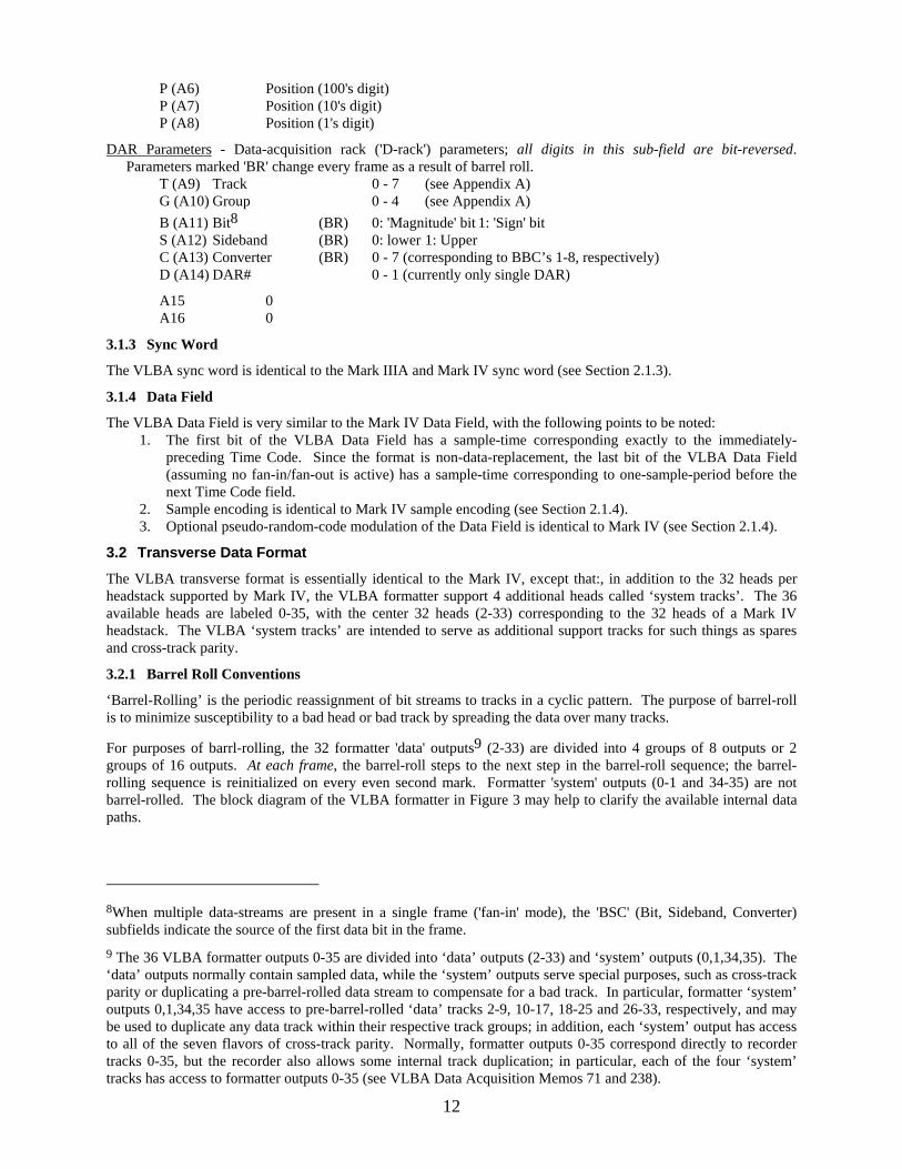
DAR Parameters - Data-acquisition rack ('D-rack') parameters; all digits in this sub-field are bit-reversed. Parameters marked 'BR' change every frame as a result of barrel roll.
T (A9) Track 0 - 7 (see Appendix A) G (A10) Group 0 - 4 (see Appendix A) B (A11) Bit8 (BR) 0: 'Magnitude' bit 1: 'Sign' bit S (A12) Sideband (BR) 0: lower 1: Upper C (A13) Converter (BR) 0 - 7 (corresponding to BBC’s 1-8, respectively) D (A14) DAR# 0 - 1 (currently only single DAR)
A15 0 A16 0
3.1.3 Sync Word
The VLBA sync word is identical to the Mark IIIA and Mark IV sync word (see Section 2.1.3).
3.1.4 Data Field
The VLBA Data Field is very similar to the Mark IV Data Field, with the following points to be noted: 1. The first bit of the VLBA Data Field has a sample-time corresponding exactly to the immediately-
preceding Time Code. Since the format is non-data-replacement, the last bit of the VLBA Data Field (assuming no fan-in/fan-out is active) has a sample-time corresponding to one-sample-period before the next Time Code field.
2. Sample encoding is identical to Mark IV sample encoding (see Section 2.1.4). 3. Optional pseudo-random-code modulation of the Data Field is identical to Mark IV (see Section 2.1.4).
3.2 Transverse Data Format
The VLBA transverse format is essentially identical to the Mark IV, except that:, in addition to the 32 heads per headstack supported by Mark IV, the VLBA formatter support 4 additional heads called ‘system tracks’. The 36 available heads are labeled 0-35, with the center 32 heads (2-33) corresponding to the 32 heads of a Mark IV headstack. The VLBA ‘system tracks’ are intended to serve as additional support tracks for such things as spares and cross-track parity.
3.2.1 Barrel Roll Conventions
‘Barrel-Rolling’ is the periodic reassignment of bit streams to tracks in a cyclic pattern. The purpose of barrel-roll is to minimize susceptibility to a bad head or bad track by spreading the data over many tracks.
For purposes of barrl-rolling, the 32 formatter 'data' outputs9 (2-33) are divided into 4 groups of 8 outputs or 2 groups of 16 outputs. At each frame, the barrel-roll steps to the next step in the barrel-roll sequence; the barrel-rolling sequence is reinitialized on every even second mark. Formatter 'system' outputs (0-1 and 34-35) are not barrel-rolled. The block diagram of the VLBA formatter in Figure 3 may help to clarify the available internal data paths.
8When multiple data-streams are present in a single frame ('fan-in' mode), the 'BSC' (Bit, Sideband, Converter) subfields indicate the source of the first data bit in the frame. 9 The 36 VLBA formatter outputs 0-35 are divided into ‘data’ outputs (2-33) and ‘system’ outputs (0,1,34,35). The ‘data’ outputs normally contain sampled data, while the ‘system’ outputs serve special purposes, such as cross-track parity or duplicating a pre-barrel-rolled data stream to compensate for a bad track. In particular, formatter ‘system’ outputs 0,1,34,35 have access to pre-barrel-rolled ‘data’ tracks 2-9, 10-17, 18-25 and 26-33, respectively, and may be used to duplicate any data track within their respective track groups; in addition, each ‘system’ output has access to all of the seven flavors of cross-track parity. Normally, formatter outputs 0-35 correspond directly to recorder tracks 0-35, but the recorder also allows some internal track duplication; in particular, each of the four ‘system’ tracks has access to formatter outputs 0-35 (see VLBA Data Acquisition Memos 71 and 238).

Though the barrel-rolling capability of the VLBA formatter is very flexible, only a simplified subset of possible barrel-rolling modes is normally used. The following guidelines (George Peck, personal communication) have been adopted by the VLBA in assigning barrel roll modes: 1. Barrel roll is disabled if the total number of tracks is not divisible by 8. 2. The 8-track barrel-roll is an 8-step sequence that is enabled when -
• the total number of tracks is divisible by 8 but not by 16, OR • the tape-writing rate is ≤ 2 Mbits/sec/track and the total number of tracks is divisible by 16.
The details of the standard VLBA 8-track barrel-roll sequence for even tracks is given in Table 8, where ‘home’ (or Roll Step 0) is the track to which a particular bit stream is written on each frame starting on an even second tick; subsequent ‘roll steps’ indicate the tracks to which that same bit stream is directed in succeeding frames; the sequence repeats until it is reset on the next even second tick. For the odd-track roll sequence, add one to all track numbers in Table 8.
Output Track Home track
Roll Step
0
RollStep
1
RollStep
2
RollStep
3
RollStep
4
RollStep
5
RollStep
6
RollStep
7 2 2 16 14 12 10 8 6 4 4 4 2 16 14 12 10 8 6 6 6 4 2 16 14 12 10 8 8 8 6 4 2 16 14 12 10
10 10 8 6 4 2 16 14 12 12 12 10 8 6 4 2 16 14 14 14 12 10 8 6 4 2 16 16 16 14 12 10 8 6 4 2 18 18 32 30 28 26 24 22 20 20 20 18 32 30 28 26 24 22 22 22 20 18 32 30 28 26 24 24 24 22 20 18 32 30 28 26 26 26 24 22 20 18 32 30 28 28 28 26 24 22 20 18 32 30 30 30 28 26 24 22 20 18 32 32 32 30 28 26 24 22 20 18
Notes: 1. The ‘Home track’ is the track that would be written if no b-r. 2. For odd-track sequence, add 1 to every track number in table.
Table 8 Standard VLBA 8-track barrel-roll sequence for even tracks
3. The ‘16-track’ barrel-roll is a 16-step sequence that is enabled when • the total number of tracks is divisible by 16 • tape writing speed is ≥ 4 Mbits/sec/track.
The details of the standard VLBA 16-track barrel-roll sequence for even tracks is given in Table 9, where ‘home’ (or Roll Step 0) is the track to which a particular bit stream is written on each frame starting on an even second tick; subsequent ‘roll steps’ indicate the tracks to which that same bit stream is directed in succeeding frames; the sequence repeats until it is reset on the next even second tick. For the odd-track roll sequence, add one to all track numbers in Table 9. Output Track
Home track
Roll Step
0
Roll Step
1
Roll Step
2
Roll Step
3
Roll Step
4
RollStep
5
RollStep
6
RollStep
7
RollStep
8
RollStep
9
RollStep 10
RollStep 11
Roll Step 12
Roll Step 13
RollStep 14
RollStep 15
2 2 16 14 12 10 8 6 4 18 32 30 28 26 24 22 20 4 4 2 16 14 12 10 8 6 20 18 32 30 28 26 24 22 6 6 4 2 16 14 12 10 8 22 20 18 32 30 28 26 24 8 8 6 4 2 16 14 12 10 24 22 20 18 32 30 28 26 10 10 8 6 4 2 16 14 12 26 24 22 20 18 32 30 28 12 12 10 8 6 4 2 16 14 28 26 24 22 20 18 32 30 14 14 12 10 8 6 4 2 16 30 28 26 24 22 20 18 32 16 16 14 12 10 8 6 4 2 32 30 28 26 24 22 20 18 18 18 32 30 28 26 24 22 20 2 16 14 12 10 8 6 4 20 20 18 32 30 28 26 24 22 4 2 16 14 12 10 8 6 22 22 20 18 32 30 28 26 24 6 4 2 16 14 12 10 8 24 24 22 20 18 32 30 28 26 8 6 4 2 16 14 12 10 26 26 24 22 20 18 32 30 28 10 8 6 4 2 16 14 12 28 28 26 24 22 20 18 32 30 12 10 8 6 4 2 16 14 30 30 28 26 24 22 20 18 32 14 12 10 8 6 4 2 16
13

14
32 32 30 28 26 24 22 20 18 16 14 12 10 8 6 4 2 Notes: 1. The ‘Home track’ is the track that would be written if barrel-roll is disabled. 2. For odd-track barrel-roll sequence, add 1 to every track number in table.
Table 9: Standard VLBA 16-track barrel-roll sequence for even tracks
3.2.2 Cross Track Parity
The VLBA formatter can form cross-track parity on groups of 8 or 16 formatter ‘data’ outputs and direct these (post barrel-roll) cross-track-parity data streams to the formatter ‘system’ outputs. In particular, cross-track parity from ‘8-track’ groups 2-9, 10-17, 18-25 and 26-33 may be written to any of the formatter ‘system’ outputs 0,1,34 or 35. Additionally, cross-track parity from ‘16-track’ groups 2-17, 10-25 and 18-33 may be written to any of the formatter ‘system’ outputs. The purpose of the cross-track parity data streams is to compensate for the loss of a single track of data within the group of tracks protected by the cross-track parity. This use of this feature has been designed into the VLBA correlator, but the author is unaware of its use to date.
3.2.3 Data-Multiplex (Fan-In/Fan-Out) Format
Although the VLBA formatter has extreme flexibility in the selection of fan-out track assignment, simple conventions have been adopted for standard recording modes, as outlined below. The user may arbitrarily assign any BBC-sideband to any CHANNEL. Special fan-out track assignments for special modes are not necessarily precluded.
3.2.3.1 Data-Multiplex Track-Assignment Conventions
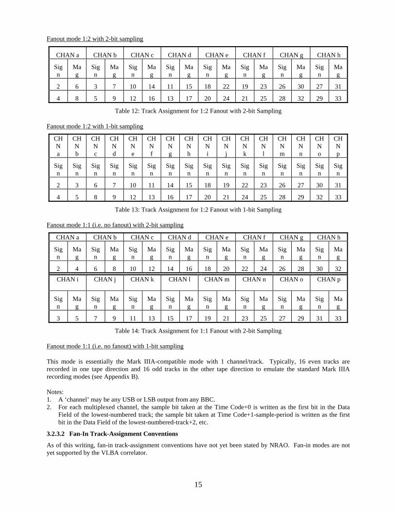
The fanout conventions adopted by the VLBA are given in the tables below. For fan-out modes, the bit ordering for a single data stream is from the top to the bottom of an individual column in a table.
Fan-out mode 1:4 with 2-bit sampling
CHAN a CHAN b CHAN c CHAN d
Sign Mag Sign Mag Sign Mag Sign Mag
2 10 3 11 18 26 19 27
4 12 5 13 20 28 21 29
6 14 7 15 22 30 23 31
8 16 9 17 24 32 25 33
Table 10: Track Assignment for 1:4 Fanout with 2-bit Sampling
Fan-out mode 1:4 with 1-bit sampling
CHAN a
CHAN b
CHAN c
CHAN d
CHAN e
CHAN f
CHAN g
CHAN h
Sign Sign Sign Sign Sign Sign Sign Sign
2 3 10 11 18 19 26 27
4 5 12 13 20 21 28 29
6 7 14 15 22 23 30 31
8 9 16 17 24 25 32 33
Table 11: Track Assignment for 1:4 Fanout with 1-bit Sampling
15
Fanout mode 1:2 with 2-bit sampling
CHAN a CHAN b CHAN c CHAN d CHAN e CHAN f CHAN g CHAN h
Sign
Mag
Sign
Mag
Sign
Mag
Sign
Mag
Sign
Mag
Sign
Mag
Sign
Mag
Sign
Mag
2 6 3 7 10 14 11 15 18 22 19 23 26 30 27 31
4 8 5 9 12 16 13 17 20 24 21 25 28 32 29 33
Table 12: Track Assignment for 1:2 Fanout with 2-bit Sampling
Fanout mode 1:2 with 1-bit sampling
CHN a
CHN b
CHN c
CHN d
CHN e
CHN f
CHN g
CHN h
CHN i
CHN j
CHN k
CHN l
CHN m
CHN n
CHN o
CHN p
Sign
Sign
Sign
Sign
Sign
Sign
Sign
Sign
Sign
Sign
Sign
Sign
Sign
Sign
Sign
Sign
2 3 6 7 10 11 14 15 18 19 22 23 26 27 30 31
4 5 8 9 12 13 16 17 20 21 24 25 28 29 32 33
Table 13: Track Assignment for 1:2 Fanout with 1-bit Sampling
Fanout mode 1:1 (i.e. no fanout) with 2-bit sampling
CHAN a CHAN b CHAN c CHAN d CHAN e CHAN f CHAN g CHAN h
Sign
Mag
Sign
Mag
Sign
Mag
Sign
Mag
Sign
Mag
Sign
Mag
Sign
Mag
Sign
Mag
2 4 6 8 10 12 14 16 18 20 22 24 26 28 30 32 CHAN i
CHAN j
CHAN k
CHAN l
CHAN m
CHAN n
CHAN o
CHAN p
Sign
Mag
Sign
Mag
Sign
Mag
Sign
Mag
Sign
Mag
Sign
Mag
Sign
Mag
Sign
Mag
3 5 7 9 11 13 15 17 19 21 23 25 27 29 31 33
Table 14: Track Assignment for 1:1 Fanout with 2-bit Sampling
Fanout mode 1:1 (i.e. no fanout) with 1-bit sampling
This mode is essentially the Mark IIIA-compatible mode with 1 channel/track. Typically, 16 even tracks are recorded in one tape direction and 16 odd tracks in the other tape direction to emulate the standard Mark IIIA recording modes (see Appendix B).
Notes: 1. A ‘channel’ may be any USB or LSB output from any BBC. 2. For each multiplexed channel, the sample bit taken at the Time Code+0 is written as the first bit in the Data
Field of the lowest-numbered track; the sample bit taken at Time Code+1-sample-period is written as the first bit in the Data Field of the lowest-numbered-track+2, etc.
3.2.3.2 Fan-In Track-Assignment Conventions
As of this writing, fan-in track-assignment conventions have not yet been stated by NRAO. Fan-in modes are not yet supported by the VLBA correlator.

16
3.3 Recorder Characteristics
3.3.1 Transport
The VLBA transport is mechanically identical to the Mark IV transport, although the control electronics has been significantly modified. Control of the VLBA system is with the MCB (Monitor and Control Bus).
3.3.2 Headstack
The VLBA uses a single headstack which is identical to the Mark IV headstack (see Section 2.3.2), except that all 36 heads are supported. The headstack can be electronically switched between read and write capability.
3.3.3 Headstack Positioner
The VLBA headstack positioner is identical to the Mark IV headstack positioner (see Section 2.3.3).
3.4 Physical Recording-Format Conventions
3.4.1 Longitudinal
Like the Mark IV, the longitudinal bit density along a track is determined entirely by the writing data rate and the tape speed. Although the design density of the VLBA system is ~56,250 bpi/track, operations are currently being done at ~33,000 bpi/track. Since the maximum per-track-data-rate of the VLBA system is ~9 Mbits/sec, all recording modes can be supported at ~33,000 bpi. Note that the recording speed must be slightly different for the ‘data-replacement’ and ‘non-data-replacement’ formats in order to keep the longitudinal density constant. Plans currently exist to increase the density to ~56,000 sometime in 1996.
3.4.2 Transverse
The design specification for the VLBA is 16 passes of the tape writing all 36 tracks. Currently, the VLBA is operating in a 14-pass mode (i.e. 14 passes with all 36 head writing on each pass), with the possibility to upgrade to a 16-pass mode in the future.
Figure 4 illustrates the layout of recorded tracks across the tape for the ‘14-pass’ operating mode. This mode requires that the headstack be positioned to 14 different positions in such a way that there is non-interference between adjacent tracks. Seven of the positions are recorded in the forward direction, spaced at 48 um; with a 38 um track width; this provides a 10 um guard band between these tracks. The forward-tape-motion headstack positions have been chosen to be -319, -271, -223, -175, -127, -79 and -31um (by convention, negative headstack positions are away from the transport deckplate; headstack position ‘0’ is calibrated to center the headstack on the tape). This can be visualized as a group of seven adjacent parallel stripes on the tape all written by the same head. This group of seven stripes is widely separated from the group written in the same-tape-motion-direction by adjacent heads; the space in between, as explained in the next paragraph, is for a group of seven tracks written in the reverse-motion direction.
The reverse-tape-motion headstack positions are also chosen with a spacing of 48um; in particular, the headstack positions are 31, 79 127, 175 223 271 and 319 um. This groups the reverse-direction tracks written by head n into seven parallel stripes straddled on the positive-headstack-position side by the forward-written tracks laid down by the head n and on the negative-headstack-position side by the group of seven parallel tracks written in the forward direction by head n-1. Note that the forward-motion group of tracks is separated from the reverse-direction group of tracks by 24 um (track edge to track edge), providing a larger guard band 14 um larger between the forward/reverse track groups than between tracks within the same group. The recognizes the fact that the forward-direction/reverse-direction tracking signature of the transport is generally poorer than repeatability in the same tape-motion direction.
Note that multiple passes may be written at the each headstack position (in the same tape-motion direction) so long as exclusive sets of heads are recorded on each pass.
4. Mark IIIA Tape Format and Recording Modes
4.1 Longitudinal Data Format
The Mark IIIA tape-frame format is identical to the Mark IV format except for the auxiliary-data information. The auxiliary-data field in each case contains 64 bits (16 hex numbers). Both are protected by the 12-bit CRC code in the header block (as is the time code). Of course, the Mark IIIA system is limited to 1 bit/sample and 1 chan/track, so there is no capability to support fan-in or fan-out as on the Mark IV and VLBA systems.

17
4.1.1 Time Code & CRC
The Mark IIIA time code and CRC fields are identical to the Mark IV time code and CRC fields (see Section 2.1.1).
4.1.2 Auxiliary Data
The Mark IIIA auxiliary data field is common across all tracks and can be written as 16 hex digits (in the order written to tape):
vvwxwxyzyzFFaabb
where
vv: hex 'FF' for forward calibration (odd passes) hex 'FE' for reverse calibration (even passes) hex 'FD' for uncalibrated position Note: In the VLBA emulation of Mark IIIA, 'vv' is binary-encoded to be the VLBA track number (4-31, corresponding to Mark IIIA tracks 1-28); see Appendix A.
wxyz: 0000-3999 positive micron positions (bcd encoded) 4000-7999 negative micron positions (bcd encoded); (4000, 7999 indicate positions of 0, -3999 respectively)
FF: hex characters FF
aa: Formatter status and error flags
bit 7 time sync error bit 6 primary power fail bit 5 framing error bit 4 timing error bits 3-2 input source bits 1-0 formatter mode
bb: bits 7-0 hardware ID
The first 48 bits of the aux-data (ttwxwxyzyzFF) are software-controllable; the last 16 bits (aabb) are fixed by the Mark IIIA formatter. The apparently-peculiar encoding of head position is an attempt to remove DC bias from the aux-data field, which sometime causes decoding problems on older playback drives at the correlators. Mark IIIA systems using control software other than that provided by NASA Goddard Space Flight Center may not write the first 48 bits of the aux-data field in the manner described.
4.1.3 Sync Word
The Mark IIIA sync word is identical to the Mark IV sync word.
4.1.4 Data Field
The Mark IIIA Data Field is identical to the Mark IV Data Field, but with the following restrictions: 1. Only 1-bit sampling is supported. 2. No fan-in or fan-out modes are supported (i.e. 1 channel maps to 1 track at all times) 3. No data-modulation is supported.
4.2 Transverse Data Format
The Mark IIIA formatter writes to the center 28 heads 36 heads available on the headstack; the headstack is identical to the Mark IV and VLBA headstack. Each head is assigned to a single BBC USB/LSB channel according to the recording mode; no multiplexing or barrel-rolling is supported.
4.3 Recording Modes and Track Assignments
The Mark IIIA formatter supports four fixed mappings of video-converter channels to tracks, designated modes A-D, according to the following table:

18
VLBA Track#
Mark 3A Track#
Mark 3A Group#
Mode A
Mode B
Mode C
Mode D
Mode E
4 1 U1 U1 U2 U1 U1 6 3 U3 U3 U4 U1 U3 8 5 U5 U5 U6 U1 U5
10 7 1 U7 U7 U8 U1 U7 12 9 U9 U9 U10 U1 U9 14 11 U11 U11 U12 U1 U11 16 13 U13 U13 U14 U1 U13 18 15 L1 L1 U1 U1 U1 20 17 L3 L3 U3 U1 U3 22 19 L5 L5 U5 U1 U5 24 21 3 L7 L7 U7 U1 U7 26 23 L9 L9 U9 U1 U9 28 25 L11 L11 U11 U1 U11 30 27 L13 L13 U13 U1 U13 5 2 U2 U1 U2 U1 U1 7 4 U4 U3 U4 U1 U3 9 6 U6 U5 U6 U1 U5
11 8 2 U8 U7 U8 U1 U7 13 10 U10 U9 U10 U1 U9 15 12 U12 U11 U12 U1 U11 17 14 U14 U13 U14 U1 U13 19 16 L2 L1 U1 U1 U1 21 18 L4 L3 U3 U1 U3 23 20 L6 L5 U5 U1 U5 25 22 4 L8 L7 U7 U1 U7 27 24 L10 L9 U9 U1 U9 29 26 L12 L11 U11 U1 U11 31 28 L14 L13 U13 U1 U13
Table 15: Mark IIIA Data-Recording Modes and Track Assignments
Notes: 1. U - Upper sideband output from video-converter 2. L - Lower-sideband output from video-converter 3. Mode A - 28 track recorded in one pass for wideband continuum 4. Mode B - 14 track recorded in each pass for continuum 5. Mode C - 14 track per pass using all the upper-sideband outputs from all 14 video-converters 6. Mode D - 1 track recorded per pass for spectroscopy
Mode E is a ‘software mode’ which is realized by alternating between hardware modes B and C and enabling a single group of tracks on each pass.
4.4 Recorder Characteristics
4.4.1 Tape Transport
The Mark IIIA tape transport is essentially identical to the Mark IV transport (see Section 2.3.1). Note, however, that the mechanical upgrade needed to support ‘thin’ (<=16 um thickness) tape, which is mandatory on Mark IV systems, may not be implemented on all Mark IIIA systems. Such unupdated systems may cause damage to ‘thin’ tape and should not be used with thin tape.

19
4.4.2 Headstack
The Mark IIIA uses two headstacks, each mounted on an independent positioner. One headstack is dedicated to writing and the other to playback. Both headstacks are identical to the Mark IV headstacks (see Section 2.3.2), except that only the central 28 heads (numbered 4-31) are used.
4.4.3 Headstack Positioner
The Mark IIIA headstack positioners are identical to the Mark IV headstack positioners (see Section 2.3.3).
4.5 Physical Recording-Format Conventions
4.5.1 Longitudinal
The Mark IIIA system is generally operated at 33,333 bpi/track, which results in tape recording speeds of 270 ips and sub-octaves (135 ips, 67.5 ips, etc.). Only Mark IIIA systems which use ‘thin’ (<=16 um thickness) tape, which has better magnetic performance, may use the higher bit densities supported by the Mark IV and VLBA systems; such systems must have installed the mechanical upgrade to properly support ‘thin’ tape.
4.5.2 Transverse
The Mark IIIA has traditionally written tapes with two different sets of headstack positions, depending on the number of tracks recorded. Mode A (28-tracks) is recorded in a 12-pass format as detailed in Figure 5. Modes B and C (14-track modes) are written in a 24-pass format as detailed in Figure 6.
5. Standard Recording Modes and Inter-Compatibility
Table 16 and Table 17 give parameters for the set of ‘standard’ Mark IV and VLBA recording modes10. Each mode is given a designation of the form:
<total data rate> - <#channels> - <#bits/sample>
For example, mode 128-4-2 indicates a recording rate of 128 Mbits/sec, covering 4 channels sampled at 2 bits. For purposes of this designation, a channel is a single USB or LSB output from a video converter (BBC). Table 16 covers the most-common continuum observing modes and Table 17 covers the most-common spectroscopic modes. Note that all ‘standard’ VLBA observing modes are included in these tables. Also included are several ‘Mark III compatibility’ modes which should be considered when operating Mark IV and Mark IIIA simultaneously.
Note that the three-number mode designator can be ambiguous with respect to the details of fan-out, tape-speed and data-rate/track. For example, the 64-4-2 mode can be recorded on 8 tracks at 8 Mbits/sec/track or on 16 tracks at 4 Mbits/sec/track. In these cases, care must be taken to specify the actual recording mode by specifying fan-out or tape-speed or data-rate/track.
Compatibility with the following other VLBI data-acquisition systems (DAS) is indicated for each mode: 1. VLBA-8: standard VLBA system with 8 BBC’s and either one or two tape drives 2. VLBA-14: ‘geodetic’ VLBA system augmented to 14 BBC’s for full compatibility with the Mark IIIA
system. 3. Mark 3A: standard Mark IIIA with 14 BBC’s
Known or expected compatibility with correlators either existing or under-development is also indicated, along with the expected processing speed-up factors for each mode.
Many variations on the modes listed in Table 16 and Table 17 are supported by Mark IV and VLBA hardware, but their use should be limited to special circumstances to avoid non-standard configurations.
10The VLBA ‘standard’ modes are defined in ‘Standard VLBA Observing Modes’, J.D. Romney, 27 Jan 1993, and are a subset of the VLBA ‘basic’ modes which are defined in ‘Basic VLBA Recording Modes’, R.C. Walker, 20 Jan 1993.

Mode Total #chans Bits/samp Total BW Smp Rate Tk Rate #tracks Fan-Out VLBA-8 VLBA-14 Mark 4 Mark 3A VLBA Mark 4 EVN Mark 3ADesignation (Mbits/sec) (MHz) (Msamp/s) (Mbits/sec) (per pass) (bitstream/ DAS DAS DAS DAS Corr Corr Corr Corr
track) (S=stndrd) (see Notes) (speedup) (speedup) (speedup) (speedup)512-16-1 512 16 1 256 32 8 64 0.25 S(2 drvs) Y(2 drvs) Y - 1 - 1 -256-8-1 256 8 1 128 32 8 32 0.25 S Y Y - 1 - 1 -
128-16-1 128 16 1 64 8 4 32 0.5 Special Y Y N 2 4 4 1128-16-1 128 16 1 64 8 8 16 1 Special Y Y Y 1 2 2 0.5128-8-1 128 8 1 64 16 4 32 0.25 S Y Y - 2 4 4 -64-16-1 64 16 1 32 4 2 32 0.5 Special Y Y N 4 8 8 264-16-1 64 16 1 32 4 4 16 1 Special Y Y Y 2 4 4 164-4-1 64 4 1 32 16 4 16 0.25 S Y Y - 2 4 4 -32-2-1 32 2 1 16 16 4 8 0.25 S Y Y - 2 4 4 -16-2-1 16 2 1 8 8 2 8 0.25 S Y Y Y 4 8 8 -8-2-1 8 2 1 4 4 2 4 0.5 S Y Y Y 4 8 8 -
2048-32-2 2048 32 2 512 32 16 128 0.5 - - 4 hdstks - - 1 1 -1024-16-2 1024 16 2 256 32 16 64 0.5 - - Y - - 1 1 -512-8-2 512 8 2 128 32 8 64 0.25 S(2 drvs) Y(2 drvs) Y - 1 - 1 -
512-16-2 512 16 2 128 16 8 64 0.5 Special Y Y - 1 2 2 -256-8-2 256 8 2 64 16 8 32 0.5 S Y Y - 1 2 2 -
'Primary' VLBA mode 128-4-2 128 4 2 32 16 4 32 0.25 S Y Y - 2 4 4 -VSOP mode 128-2-2 128 2 2 32 32 8 16 0.25 Special Y Y - 1 2 2 -
64-2-2 64 2 2 16 16 4 16 0.25 S Y Y - 2 4 4 -32-2-2 32 2 2 8 8 2 16 0.25 S Y Y 1-bit only 4 8 8 -16-2-2 16 2 2 4 4 2 8 0.5 S Y Y 1-bit only 4 8 8 -8-2-2 8 2 2 2 2 2 4 1 S Y Y 1-bit only 4 8 8 -
Notes:1. VLBA-8 is 'standard' VLBA system with 8 BBC's (may have one or two tape drives).2. VLBA-8 modes labelled as 'S' are 'standard' VLBA recording modes as described in "Standard VLBA Observing Modes" by J.D. Romney, 27 Jan 93.3. VLBA modes labelled as 'Special' are accessible to VLBA system, but not among 'standard' modes defined by VLBA.4. Mode 128-16-1 has highest bit-rate compatibility between Mark IIIA and VLBA, although in practice Mark 3A would probably record in mode 112-14-1 for tape-usage efficiency. 5. Mode 64-16-1 has 64 Mbit/sec compatibility between Mark IIIA and VLBA, although in practice Mark 3A would probably record in mode 56-14-1 for tape-usage efficiency.6. Mode 512-16-2 is the only VLBA 512 Mbit/sec mode compatible with Mark IV correlator.7. Mark 4 correlator cannot support modes which reproduce at >32 Msamples/sec at fixed 16 Mbit/sec/track playback rate.8. Mark 4 DAS and VLBA-14 can be configured to be compatible with all Mark 3A modes.9. Recording modes with more than 8 channels may require 2 passes through the VLBA correlator.10. Mark IV systems require external filters to support BBC channel bandwidths of 0.25 and 1.0 MHz.
Table 16 Standard Mark 4 Continuum Modes and Compatibility with VLBA and Mark 3A
20

BW/line #lines Total #chans Bits/samp Total BW Smp Rate Tk Rate #tracks Fan-Out VLBA-8 VLBA-14 Mark 4 Mark 3A VLBA Mark 4 EVN Mark 3A(MHz) Mode (Mbits/sec) (MHz) (Msamp/s) (Mbits/sec) (per pass) (bitstreams/ DAS DAS DAS DAS Corr Corr Corr Corr
Designation track) (S=stndrd) (speedup) (speedup) (speedup) (speedup)52 1 256-4-2 256 4 2 64 32 8 32 0.25 S Y Y - 1 - 2 -28 1 128-2-2 128 2 2 32 32 8 16 0.25 S Y Y - 1 - 2 -16 1 64-1-2 64 1 2 16 32 8 8 0.25 S Y Y - 1 - 2 -8 1 32-1-2 32 1 2 8 16 4 8 0.25 S Y Y - 2 4 4 -4 1 16-1-2 16 1 2 4 8 2 8 0.25 S Y Y 1-bit only 4 8 8 -2 1 8-1-2 8 1 2 2 4 2 4 0.5 S Y Y 1-bit only 4 8 8 -1 1 4-1-2 4 1 2 1 2 2 2 1 S Y Y 1-bit only 4 8 8 -
0.5 1 2-1-2 2 1 2 0.5 1 2 1 2 S Y Y 1-bit only 4 8 8 -
52 2 512-8-2 512 8 2 128 32 8 64 0.25 S(2 drvs) Y Y - 1 - 2 -28 2 256-4-2 256 4 2 64 32 8 32 0.25 S Y Y - 1 - 2 -16 2 128-2-2 128 2 2 32 32 8 16 0.25 S Y Y - 1 - 2 -8 2 64-2-2 64 2 2 16 16 4 16 0.25 S Y Y - 2 4 4 -4 2 32-2-2 32 2 2 8 8 2 16 0.25 S Y Y 1-bit only 4 8 8 -2 2 16-2-2 16 2 2 4 4 2 8 0.5 S Y Y 1-bit only 4 8 8 -1 2 8-2-2 8 2 2 2 2 2 4 1 S Y Y 1-bit only 4 8 8 -
0.5 2 4-2-2 4 2 2 1 1 2 2 2 S Y Y 1-bit only 4 8 8 -0.25 2 2-2-2 2 2 2 0.5 0.5 2 1 4 S Y Y 1-bit only 4 8 8 -
28 4 512-8-2 512 8 2 128 32 8 64 0.25 S(2 drvs) Y Y - 1 - 2 -16 4 256-4-2 256 4 2 64 32 8 32 0.25 S Y Y - 1 - 2 -8 4 128-4-2 128 4 2 32 16 4 32 0.25 S Y Y - 2 4 4 -4 4 64-4-2 64 4 2 16 8 2 32 0.25 S Y Y 1-bit only 4 8 8 -2 4 32-4-2 32 4 2 8 4 2 16 0.5 S Y Y 1-bit only 4 8 8 -1 4 16-4-2 16 4 2 4 2 2 8 1 S Y Y 1-bit only 4 8 8 -
0.5 4 8-4-2 8 4 2 2 1 2 4 2 S Y Y 1-bit only 4 8 8 -0.25 4 4-4-2 4 4 2 1 0.5 2 2 4 S Y Y 1-bit only 4 8 8 -
16 8 512-8-2 512 8 2 128 32 8 64 0.25 S(2 drvs) Y Y - 1 - 2 -8 8 256-8-2 256 8 2 64 16 8 32 0.5 S Y Y - 1 2 2 -4 8 128-8-2 128 8 2 32 8 4 32 0.5 S Y Y 1-bit only 2 4 4 -2 8 64-8-2 64 8 2 16 4 2 32 0.5 S Y Y 1-bit only 4 8 8 -1 8 32-8-2 32 8 2 8 2 2 16 1 S Y Y 1-bit only 4 8 8 -
0.5 8 16-8-2 16 8 2 4 1 2 8 2 S Y Y 1-bit only 4 8 8 -0.25 8 8-8-2 8 8 2 2 0.5 2 4 4 S Y Y 1-bit only 4 8 8 -
Table 17 Standard Mark 4 Spectroscopic Modes and Compatibility with VLBA and Mark 3A
21

22
6. Appendix A: Track Numbering and Aux-Data Track ID’s in Mark IIIA, Mark IV, VLBA
There has arisen some confusion as to track numbering and track-identifying information in the Mark IIIA, Mark IV, and VLBA data-acquisition systems. The intent of this appendix is to help clarify this situation.
Track-Numbers vs. Head-Numbers
For purposes of convenience, and in deference to common usage, we will use the word 'track-number' when we really should be using the word 'head-number'. Because all three of these systems use movable headstacks and multiple passes, the true track-number quickly becomes ambiguous, but the 'head-number' within the headstack always remains unambiguously defined. We should note additionally that, due to the movable headstacks, a given track on the tape is potentially also readable by a neighboring head; so when we speak of 'head-number', at least in this note, we always mean the writing head-number.
Mark IIIA11
The Mark IIIA system uses 28 heads ('tracks'), numbered 1-28. On the Honeywell/Metrum transport, track 1 is closest to the front of the drive (closest to the user) and track 28 is closest to the deck plate; this is reversed on the Penny & Giles transport since the tape reels are mounted 'backwards'. The 28 tracks are divided into four groups, numbered 1-4. Group 1 contains the odd-numbered tracks in the range 1-13; Group 2 contains the even numbered tracks in the range 2-14; Group 3 contains the odd-numbered tracks in the range 15-27; Group 4 contains the even-numbered tracks in the range 16-28
The original Mark IIIA systems do not have the capability of writing track-specific data in the auxiliary-data field of each data-frame header, therefore no track-identification information is contained on tapes written on original Mark IIIA systems.
The VLBA system has the capability of emulating the Mark IIIA system, but includes the capability of writing track-specific identification information in the aux-data area of each data frame. When operating in this mode, the Mark IIIA aux-data field defined as 'vv' in Section 4.1.2 is written as a binary-encoded VLBA track number equal to the Mark IIIA track number plus 3 (see Table 15).
VLBA
The VLBA system uses 36 heads ('tracks'), numbered 0-35. Numbering order across the tape is similar to Mark IIIA. The 36 tracks are divided into four groups, numbered 0-3, within the VLBA tape recorder. Group 0 contains the even-numbered tracks in the range 0-16; Group 1 contains the odd-numbered tracks in the range 1-17; Group 2 contains the even-numbered tracks in the range 18-34; Group 3 contains the odd-numbered tracks in the range 19-35. The 'group' and 'track' hex digits A10 and A9 encoded into the VLBA auxiliary-data field are shown in Table 18; these ‘group’ and ‘track’ numbers are generated by the VLBA formatter and are somewhat different than the group numbers defined within the recorder.
Mark IV
The Mark IV system uses 32 heads ('tracks') in each of 2 headstacks for a total of 64 tracks, and is expandable to 4 headstacks. The tracks on each headstack are numbered 2-33, which correspond directly to VLBA tracks 2-33. The Mark IV track number is encoded into the aux-data field as a 6-bit BCD field. The headstack number is encoded into a 2-bit field in the aux-data.
Table 18 shows the track-numbering correspondence and aux-data track-ID fields in VLBA, Mark IV, Mark IIIA and VLBA emulation of Mark IIIA.
11 The older Mark III system is a subset of the Mark IIIA system. Both systems write 28 tracks, numbered in the same way, but the Mark III system has a fixed headstack and can write only a single pass on the tape.

23
VLBA Mark IV Mark IIIA
Head #
Track#
Aux-data'Group' (Digit A10)
(hex)12
Aux-data
‘Track’ (Digit A9)
(hex)13
Track#
Aux-data
Track-ID
(hex)
Track#
Aux-data
Track-ID
(hex)14
0 0 4 2 - - - - 1 1 4 0 - - - - 2 2 2 0 2 02 - - 3 3 0 0 3 03 - - 4 4 2 1 4 04 1 04 5 5 0 1 5 05 2 05 6 6 2 2 6 06 3 06 7 7 0 2 7 07 4 07 8 8 2 3 8 08 5 08 9 9 0 3 9 09 6 09 10 10 2 4 10 10 7 0A 11 11 0 4 11 11 8 0B 12 12 2 5 12 12 9 0C 13 13 0 5 13 13 10 0D 14 14 2 6 14 14 11 0E 15 15 0 6 15 15 12 0F 16 16 2 7 16 16 13 10 17 17 0 7 17 17 14 11 18 18 3 0 18 18 15 12 19 19 1 0 19 19 16 13 20 20 3 1 20 20 17 14 21 21 1 1 21 21 18 15 22 22 3 2 22 22 19 16 23 23 1 2 23 23 20 17 24 24 3 3 24 24 21 18 25 25 1 3 25 25 22 19 26 26 3 4 26 26 23 1A 27 27 1 4 27 27 24 1B 28 28 3 5 28 28 25 1C 29 29 1 5 29 29 26 1D 30 30 3 6 30 30 27 1E 31 31 1 6 31 31 28 1F 32 32 3 7 32 32 - - 33 33 1 7 33 33 - - 34 34 4 3 - - - - 35 35 4 1 - - - -
Table 18: Correspondence of track numbers and aux-data track-ID field in various systems
12Bit-reversed when written to tape (i.e. written lsb-to-msb) 13Bit-reversed when written to tape (i.e. written lsb-to-msb) 14Present on VLBA emulation of Mark IIIA system only

24
7. Appendix B: Tabular Summary of Primary Mark IIIA, Mark IV, VLBA Characteristics
The following table summarizes the salient characteristics of the Mark IIIA, Mark IV, and VLBA parameters relating to data and tape formats:
Mark IIIA Mark IV VLBA
#BBC's 14 1415 816
Max sample rate (Msamples/sec) 8 32 32
#bits/sample 1 1 or 2 1 or 2
#tracks (#supported heads) 28 6417 3618
Head spacing within headstack 698.5 um 698.5 um 698.5 um
#passes (all heads enabled) 12 16 16
Max data-rate/track (Mbits/sec)19 8 16 8
Bit density (bpi/track) ~33,000 ~56,000 ~56,00020
Multiplex fan-out (bitstreams:trk) 1:1 only 1:1, 1:2, 1:421 1:1, 1:2, 1:421
Multiplex fan-in (bitstreams:trk) None 2:1, 4:1 2:1, 4:1
Barrel-rolling N Y Y
Data-modulation N Y Y
Support of non-data-replacement N N Y22 Longitudinal track-frame length (Aux+Sync+Time+CRC +Data+Parity) [in bits]
64A +32S +52T +12C +19840D (+2500P)
64A +32S +52T +12C +19840D (+2500P)
32S +48T +16C +20000D +64A23 (+2520P)
Table 19: Comparison of Mark IIIA, Mark IV and VLBA Major Characteristics
15Expandable to 16 BBC's 16A few VLBA systems have been augmented to 14 BBC's for better compatibility with Mark IIIA. 17Expandable to 128 tracks (4 headstacks total), for a maximum total data rate of 2048 Mbits/sec 1832 data tracks plus 4 'system' tracks. 19Actual Mark III/IV bit-rate/track is 9/8 times data-rate/track due to addition of byte-parity bits. Actual VLBA bit-rate/track is slightly greater than 9/8 times data-rate/track due to non-data-replacement format. 20As of mid-1995, VLBA was still in transition from 33,000 to 56,000 bpi/track. 21A single sample bit-stream (sign or magnitude) can be fanned out to a maximum of 4 tracks. Therefore, data from 2-bit channels can actually be fanned-out to a total of 8 tracks. Mark IV and VLBA are the same in this respect. 22Can also write Mark IIIA/Mark IV-compatible data-replacement format 23Aux-data field is defined to be at end of frame in VLBA tape-frame format.

25
8. Appendix C: Revision History
Revision 1.0, 27 December 95: Original issue, largely based on Mark IV memo 205.6
Revision 1.1, 4 January 96: Fix several minor typos
Revision 1.11, 8 May 98: Fix several minor typos; add additional modes to Table 15
Revision 1.12 28 August 98: Expand Table 3 to include encoding for MkIV corr chip and MkIV formatter rear-panel outputs.
Revision 1.2 28 September 2000: Amend barrel-roll tables to be consistent with actual VLBA sequences. Revision 1.21 10 June 2005: Add footnote regarding reliability of VLBA-tape-frame auxiliary data field.

Y D D D H H M M S S s s s. CRC-12HDSTK POS
Aux Data(8 bytes+parity)
Sync Word(4 bytes+parity)
4 x 111111110
BCD Time Code & CRCC(8 bytes+parity)
ID/STATUS
HEADER DATA
20 bytes+parity 2480 bytes+parity
DataByte
P P P PPRecording Sequence
Notes: 1. Parity always ODD except Sync Word. 2. Byte to either side of Sync Word must contain at least one '0' (two '0's requested by VLBA correlator). . 3. Mark III tape frame format is identical except for contents of Aux Data field.
Data Field
DataByte
DataByte
DataByte
Even parity
~97% omitted
DATA
ARW8 Dec 95
CRCC computed over these 148 bits (not including parity)
(Header replaces20 data bytes)
a a a a b b b b r r s s t t u u
Figure 1: Mark IV Tape Frame Format
26

J J J S S S S S s s s s CRC-16
Sync Word(4 bytes+parity)
4 x 111111110
BCD Time Code & CRCC(8 bytes+parity)
HEADER DATA
12 bytes+parity 2500 bytes+parity
DataByte
P P P PPRecording Sequence
Notes: 1. Parity always ODD except Sync Word. 2. BCD digits in Time-Code and Aux-data, excep those labelled reversed, are written to tape in order msb-to-lsb. 3. Byte to either side of Sync Word must contain at least one '0'.
Data Field
DataByte
DataByte
DataByte
Even parity
~97% omitted
DATA
ARW26 May 1994
CRCC computed over these 48 bits (not including parity)
Aux Data(8 bytes+parity)
AUX-DATA
8 bytes+parity
RecorderParameters
DAR Parameters(bit-reversed digits)
SpareDigits
StationIDMJD Seconds
S R HS P P P P T G B S C D 0 0
Figure 2: VLBA Tape Frame Format
27

2-9
10-17
18-25
26-33
Select1 of 8
Select1 of 8
Sam
pler
s
Mul
tiple
x
Bar
rel-R
oll
Select1 of 36
Select1 of 36
2-9
10-17
18-25
26-33
1
0
34
35
0
1
2-9
10-17
18-25
26-33
34
35
PhysicalTracks
Formatter'Tracks'
Vid
eo In
from
BBC
's
VLBA Formatter VLBA RecorderARW
6 Nov 95
Cro
ss-tr
k pa
rity
2-9
10-1
7
18-2
5
26-3
3
2-17
10-2
5
18-3
3
2-9
10-1
7
18-2
5
26-3
3
2-17
10-2
5
18-3
3
Cro
ss-tr
k pa
rity
Select1 of 8
Select1 of 8
Select1 of 8
Select1 of 8
Select1 of 8
Select1 of 8
Select1 of 36
Select1 of 36
*All 36 inputs are actually available to each selector
*
*
*
*
Figure 3: VLBA Formatter and Recorder Signal Paths
28

Headstackposition (um)
Head n reverse passes Head n+1 forward passes Head n+1 reverse passes
Across tape
-319 -271 -223 -175 -127 -79 -31 31 79 127 175 223 271 319
38um
trac
k w
idth
10um
gua
rd b
and
24um
for/r
ev g
uard
ban
d
Head n forward passes
Towards VLBA deckplate
698.5 um head pitch (head spacing)
Tape Motion (as viewed looking down onto magnetic surface)
ARW26 Dec 1995
-319 -271 -223 -175 -127 -79 -31 31 79 127 175 223 271 319 319
Head 35Reverse
'Back'Tape Edge
112 um
-319
Head 0Forward
'Front'Tape Edge
112 um
Figure 4: VLBA Track Layout on Tape for 14-pass Operation
(track #’s are VLBA convention)
29

Headstackposition (um)
Head n reverse passes Head n+1 fwd passes Head n+1 rev passes
Across tape
-350 -295 -240 -185 -130 -75 0 55 110 165 220 275
38um
trac
k w
idth
17um
gua
rd b
and
37um
for/r
ev g
uard
ban
d
Head n forward passes
Towards VLBA deckplate
698.5 um head pitch (head spacing)
Tape Motion (as viewed looking down onto magnetic surface)
ARW26 Dec 1995
275
Head 31Reverse
'Back'Tape Edge
2956 um
-350
Head 4Forward
'Front'Tape Edge
2881 um
-350 -295 -240 -185 -130 -75 0 55 110 165 220 275
Trk 18 precisely centered ontape at headstack position -350um
Note: All head #'s adhere to VLBA convention
Figure 5: Mark IIIA Mode A Standard Layout on Tape
(12 28-track passes)
30

Headstackposition (um)
Odd head n+1 reverse passes
Across tape
-330 -275 -220 -165 -110 -55 0 55 110 165 220 275
38um
trac
k w
idth
17um
gua
rd b
and
55.5
um
for/r
ev g
uard
ban
d
Even head n forward passes
Towards VLBA deckplate
698.5 um head pitch (head spacing)
Tape Motion (as viewed looking down onto magnetic surface)
ARW26 Dec 1995
275
Head 31Reverse
'Back'Tape Edge
2627 um
-330
Head 4Forward
'Front'Tape Edge
3270 um
-330 -275 -220 -165 -110 -55 0 55 110 165 220 275
Note: All head #'s adhere to VLBA convention
Figure 6: Mark IIIA Mode B,C Standard Layout on Tape
(24 14-track passes)
31