mark handley usc/isi mjh@isi - cs.odu.educs778/handley/mci.pdf · [email protected]. overview ip...
TRANSCRIPT
OverviewIP MulticastReal-Time Traffic on the InternetSecuritySession AnnouncementsSession InvitationH.323Multicast Address AllocationStream ControlBetter ServiceCodecs and Media PacketizationCongestion Control for Multimedia
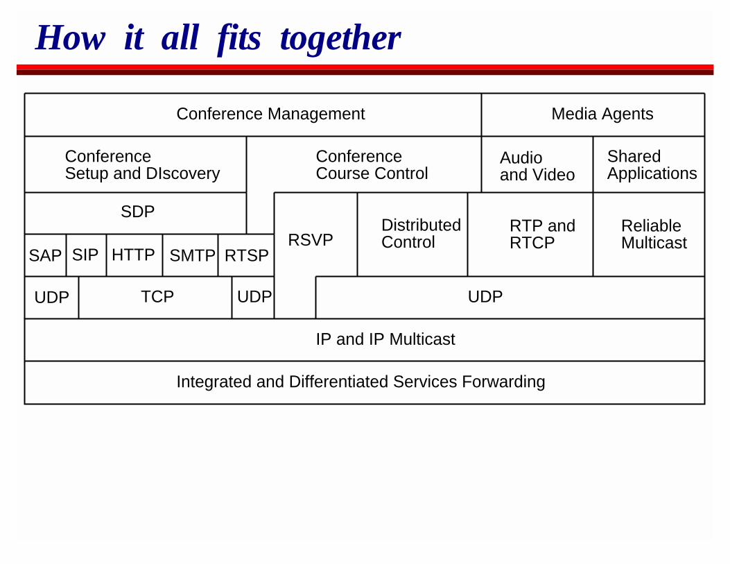
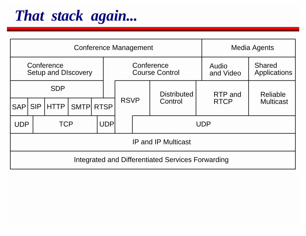
How it all fits together
IP and IP Multicast
Integrated and Differentiated Services Forwarding
UDP TCP
SAP SIP HTTP SMTP
SDP
ConferenceSetup and DIscovery
ConferenceCourse Control
RSVPDistributedControl
RTP andRTCP
ReliableMulticast
Audioand Video
SharedApplications
Conference Management Media Agents
UDPUDP
RTSP
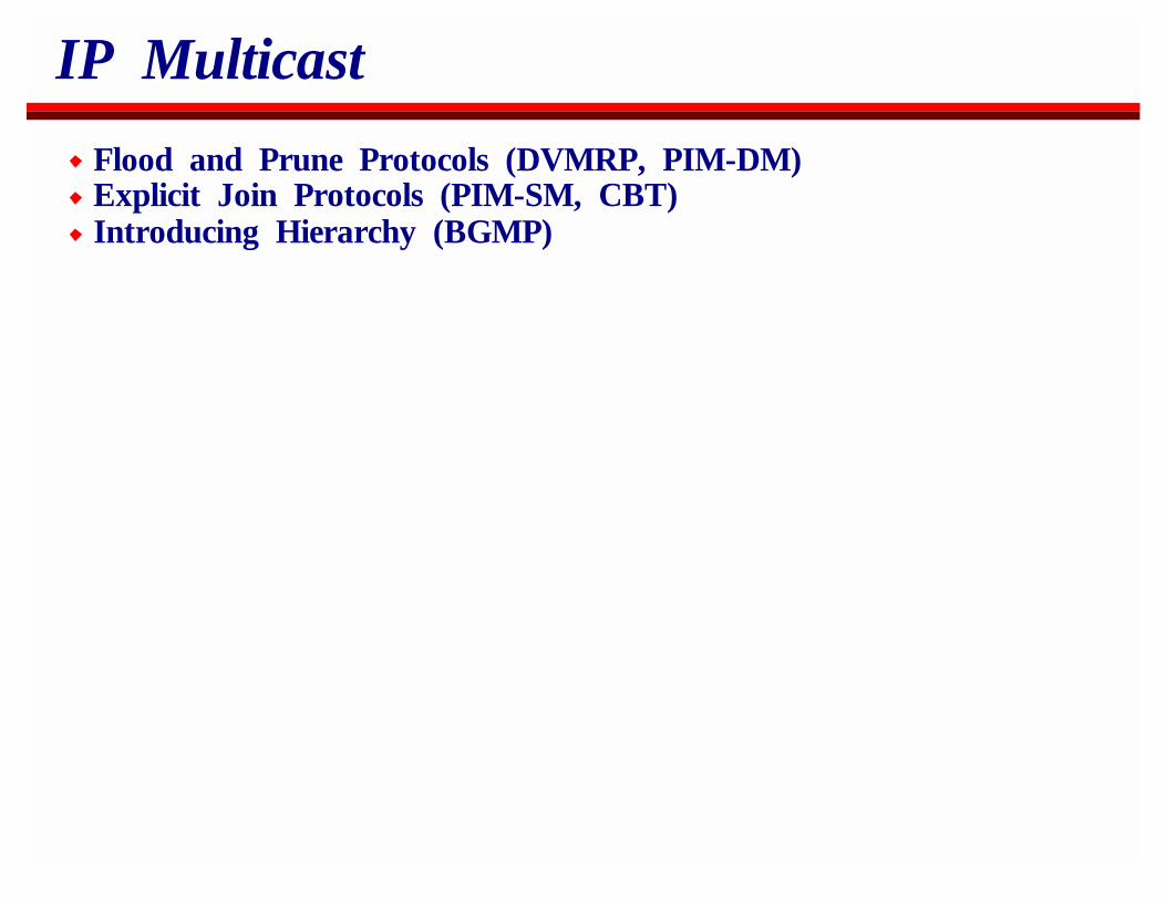
IP Multicast
Flood and Prune Protocols (DVMRP, PIM-DM)Explicit Join Protocols (PIM-SM, CBT)Introducing Hierarchy (BGMP)
Conferencing Requirements
Support many to many conferencingScale to large groups
Data should only traverse each line onceRobustness to link failures
No fate sharingEnd-systems don’t know the topology
IP Multicast
Dynamically constructs efficient, shortest path distribution treesfrom senders to receiversService Model:
Receivers announce their interestSenders just sendRouters conspire to deliver data from senders to receivers
Class D addresses
Traditionally, IP Addresses were divided into classes:Class A for networks with millions of hostsClass B for networks with thousands of hostsClass C for networks with tens to hundreds of hosts
Class D is multicast group addressesA multicast sender just sends to a class D multicast addressMulticast receivers express an interest in a class D multicastaddressIf they choose the same address, the network delivers trafficfrom the senders to the receivers.Class D addresses are in the range 224.0.0.0 to239.255.255.255.
IP Multicast Routing ProtocolsDVMRP
Distance Vector Multicast RoutingForms the basis is much of the Mbone
PIMProtocol Independent MulticastOffered in Cisco routersTwo modes: dense and sparse mode
MOSPFMulticast OSPF
CBTCore-Based TreesBetter scaling properties at the expense of non-shortest pathtrees.
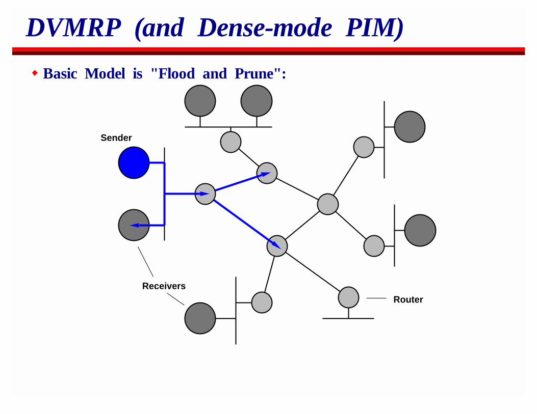
DVMRP (and Dense-mode PIM)
Basic Model is "Flood and Prune":
Sender
ReceiversRouter
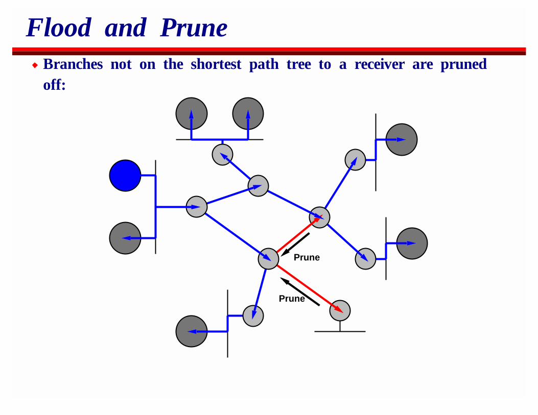
Flood and PruneBranches not on the shortest path tree to a receiver are prunedoff:
Prune
Prune
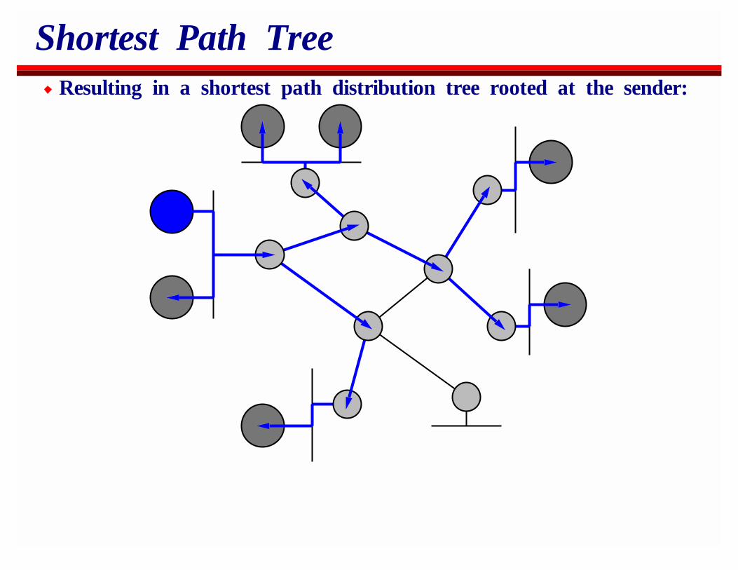
Shortest Path TreeResulting in a shortest path distribution tree rooted at the sender:
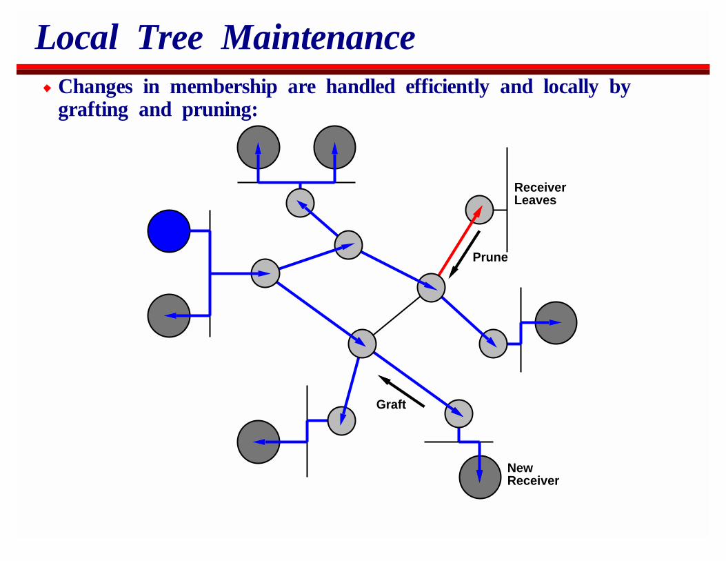
Local Tree MaintenanceChanges in membership are handled efficiently and locally bygrafting and pruning:
ReceiverLeaves
Prune
Graft
NewReceiver
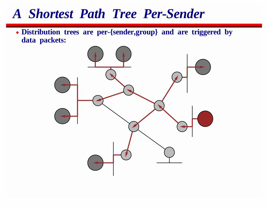
A Shortest Path Tree Per-SenderDistribution trees are per-{sender,group} and are triggered bydata packets:
Sparse-mode PIM
Instead of flooding and pruning to directly build a shortest pathtree, Sparse-mode PIM initially builds a shared tree.
The shared tree is built by sending join messages towards aRendezvous Point (RP).
Once data is flowing, the shared tree can be converted to ashortest path tree if required.
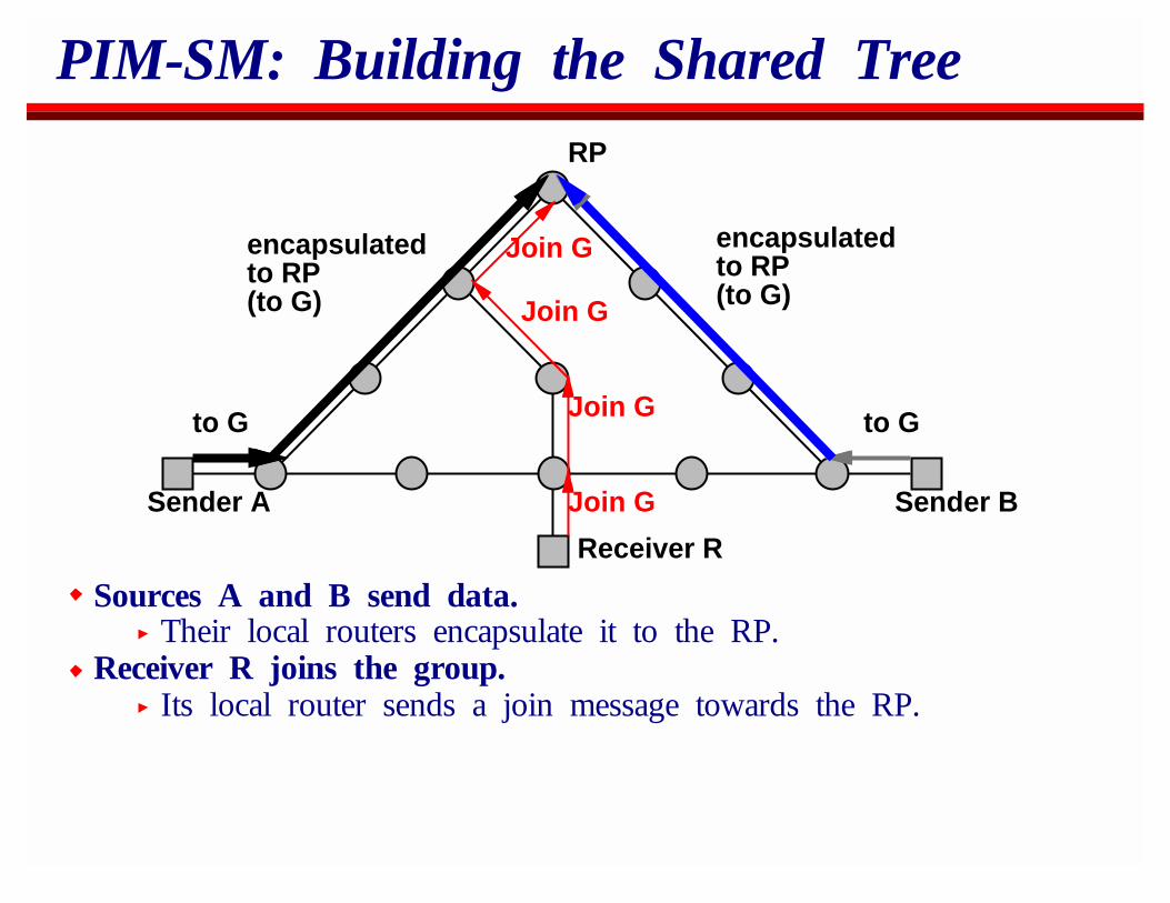
PIM-SM: Building the Shared Tree
Sender A
Receiver R
Sender B
RP
encapsulatedto RP(to G)
encapsulatedto RP(to G)
to G to G
Join G
Join G
Join G
Join G
Sources A and B send data.Their local routers encapsulate it to the RP.
Receiver R joins the group.Its local router sends a join message towards the RP.
PIM-SM: Building the Shared Tree
Sender A
Receiver R
Sender B
RP
to G to G
to G
to G
to G
to Gencapsulatedto RP(to G)
encapsulatedto RP(to G)
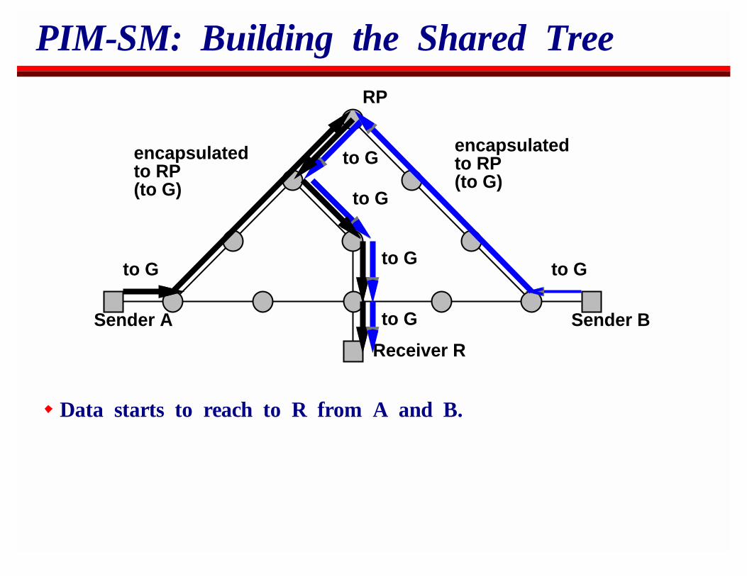
Data starts to reach to R from A and B.
PIM-SM: Building the Shared Tree
Sender A
Receiver R
Sender B
RP
encapsulatedto RP(to G)
encapsulatedto RP(to G)
to G to G
Join G for src B
Join G for src B
Join G for src B
Join G for src A
Join G for src A
Join G for src A
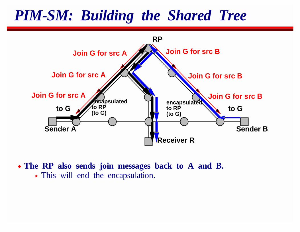
The RP also sends join messages back to A and B.This will end the encapsulation.
PIM-SM: Building the Shared Tree
Sender AReceiver R
Sender B
RP
to G to Gto G
to G
to G
to Gto G
to Gto G
to G
to G
to G
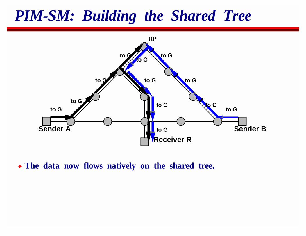
The data now flows natively on the shared tree.
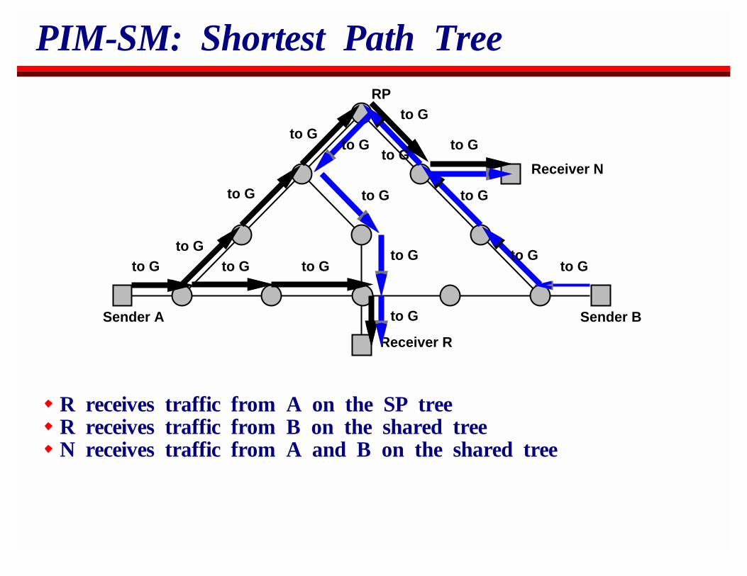
PIM-SM: Shortest Path Tree
Sender A
Receiver R
Sender B
RP
to G to Gto G
to G
to G
to Gto G
to Gto G
to G
to G
to GReceiver N
Join GJoin G
Join G for src A
Join G for src A
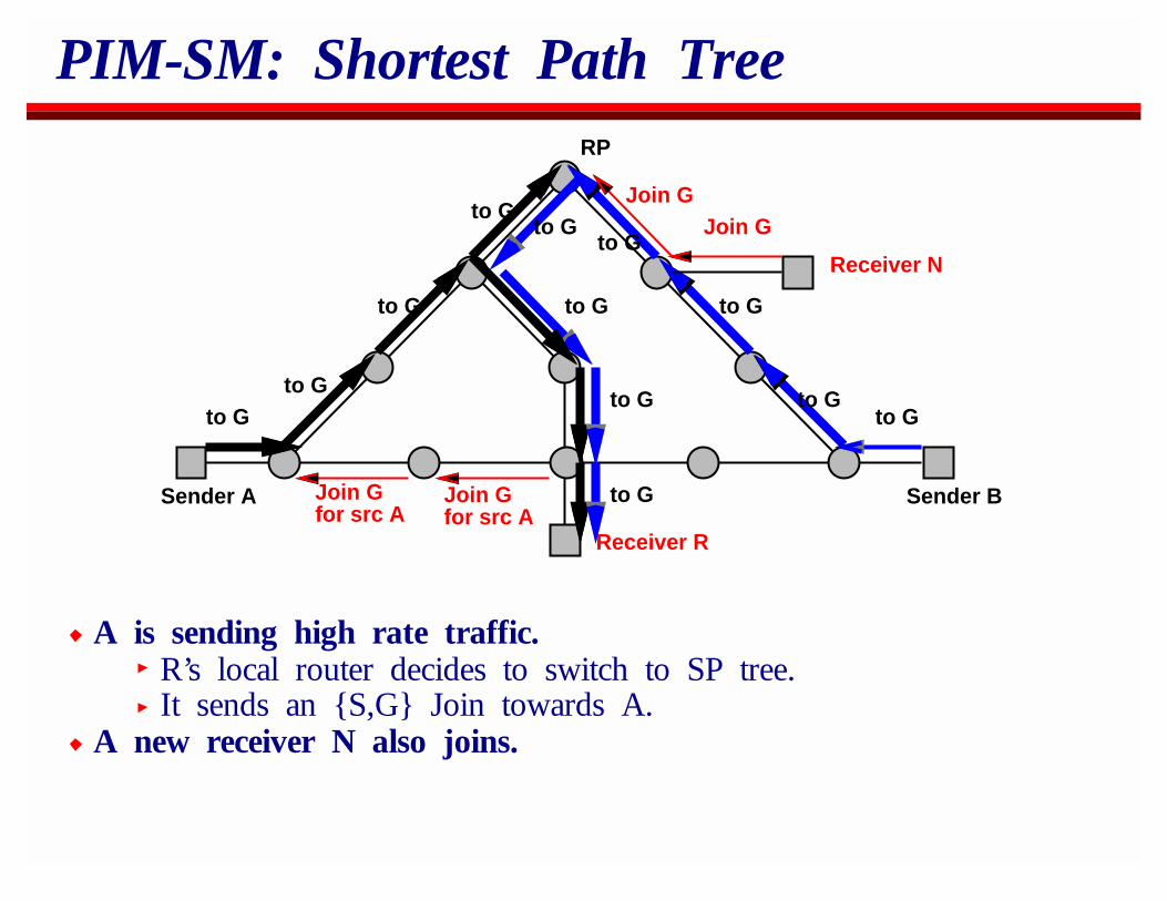
A is sending high rate traffic.R’s local router decides to switch to SP tree.It sends an {S,G} Join towards A.
A new receiver N also joins.
PIM-SM: Shortest Path Tree
Sender A
Receiver R
Sender B
RP
to G to Gto G
to G
to G
to Gto G
to Gto G
to G
to G
to GReceiver N
to G
to G
Prune Afrom G
Prune Afrom G
to G to G
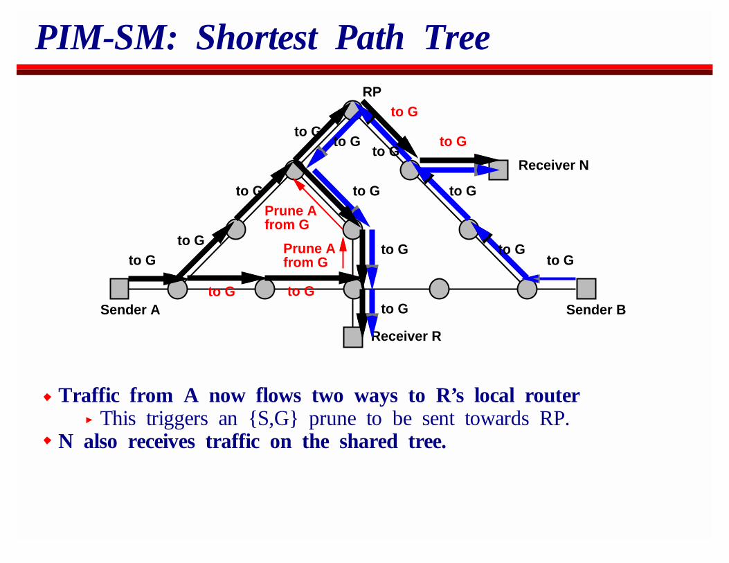
Traffic from A now flows two ways to R’s local routerThis triggers an {S,G} prune to be sent towards RP.
N also receives traffic on the shared tree.
PIM-SM: Shortest Path Tree
Sender A
Receiver R
Sender B
RP
to G to Gto G
to G
to G
to Gto G
to Gto G
to G
to G
to GReceiver N
to G
to G
to G to G
R receives traffic from A on the SP treeR receives traffic from B on the shared treeN receives traffic from A and B on the shared tree
PIM-SM: Finding the RP
The problem with PIM and CBT is how the local routersdiscover the address of the RP.
PIM-SM v1 did this through configuration.PIM-SM v2 does this by hashing the group address into adynamically generated list of candidate RPs.
Neither mechanism scales well, restricting PIM to use as anintra-domain multicast routing protocol.
Recently there’s been discussion about whether we should changethe service model to move away from rendezvous in the network.
Our alternative is BGMP/MASC.
BGMP - Interdomain Multicast
BGMP stands for Border Gateway Multicast ProtocolIt’s roughly analogous to BGP for unicast routing
Introduces hierarchy to multicast routingProvides interoperability between other multicast routingprotocolsAllows DVMRP, PIM, etc to be deployed on scales wherethey work well
Due to a tie-in with address allocation it provides a scalablesolution to the rendezvous problem.Also it should help us reduce multicast forwarding state bydynamic aggregation.
This is all still in the design and early implementation stages
BGMP - Interdomain Multicast
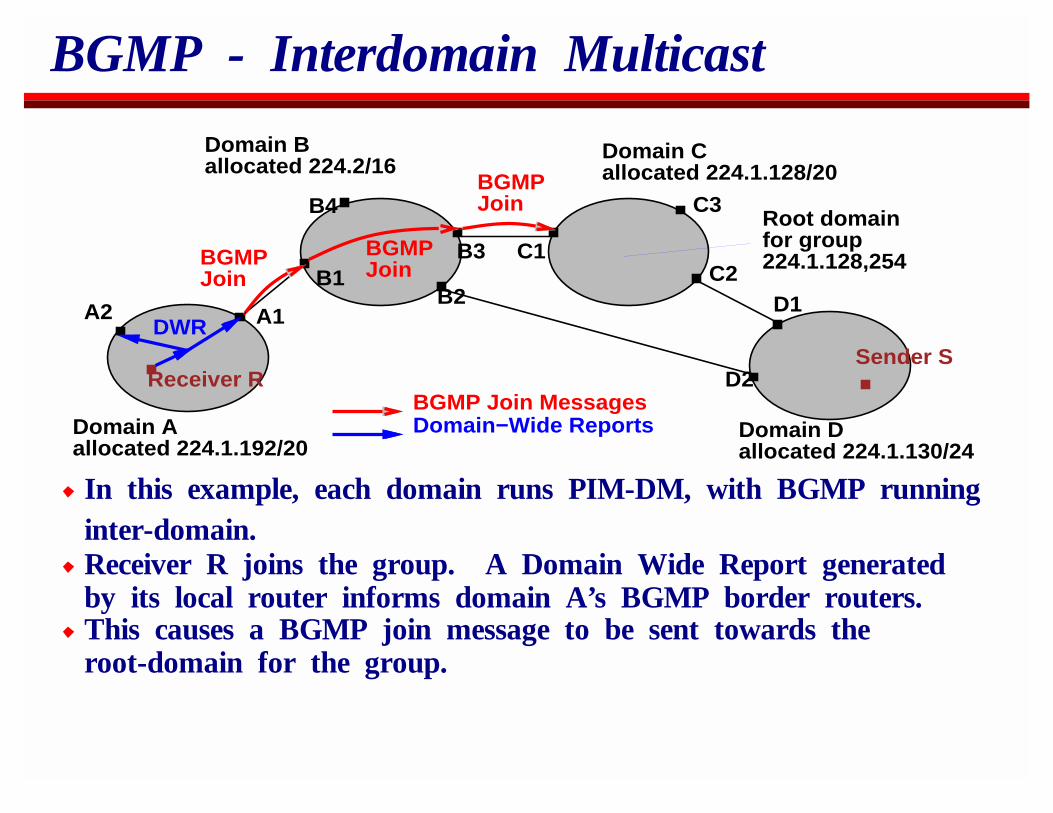
Domain Aallocated 224.1.192/20
Domain Ballocated 224.2/16
Domain Callocated 224.1.128/20
Domain Dallocated 224.1.130/24
Receiver RSender S
DWR
BGMPJoin
BGMPJoin
BGMPJoin
Root domainfor group224.1.128,254
A1A2
B1B2
B3
B4
C1C2
C3
D1
D2BGMP Join MessagesDomain−Wide Reports
In this example, each domain runs PIM-DM, with BGMP runninginter-domain.Receiver R joins the group. A Domain Wide Report generatedby its local router informs domain A’s BGMP border routers.This causes a BGMP join message to be sent towards theroot-domain for the group.
BGMP - Shared Tree of Domains
Domain A
Domain B
RS
A1A2
B1
B2
B3
B4
C1C2
C3
D1
D2
Domain D
BGMP shared treeData packets
DM−PIM prune messagesEncapsulated Data packets
Domain C(Root domain)
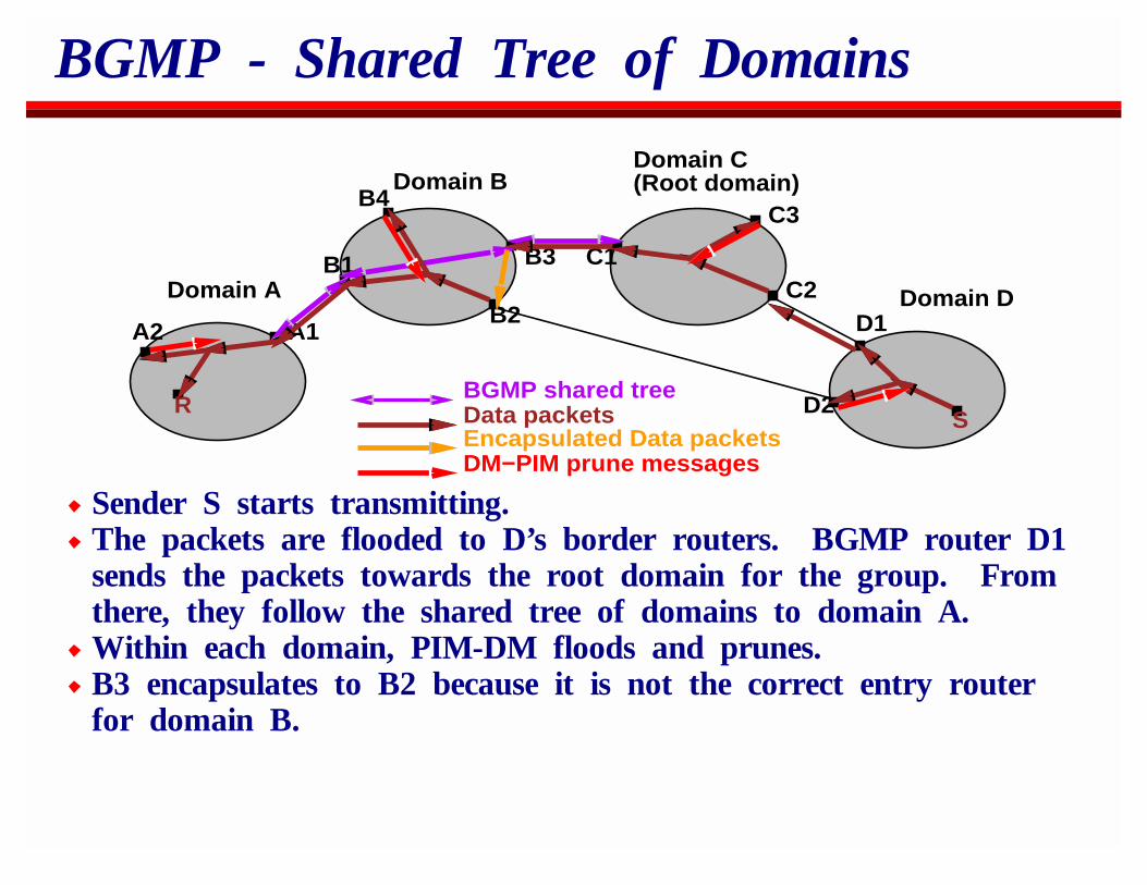
Sender S starts transmitting.The packets are flooded to D’s border routers. BGMP router D1sends the packets towards the root domain for the group. Fromthere, they follow the shared tree of domains to domain A.Within each domain, PIM-DM floods and prunes.B3 encapsulates to B2 because it is not the correct entry routerfor domain B.
BGMP - Shortest Path Branch
A1A2
B1
B2
B3
B4
C1C2
C3
D1
D2
Domain A
Domain B Domain C
RS
Domain D
Graft(S,G) BGMPJoin Message
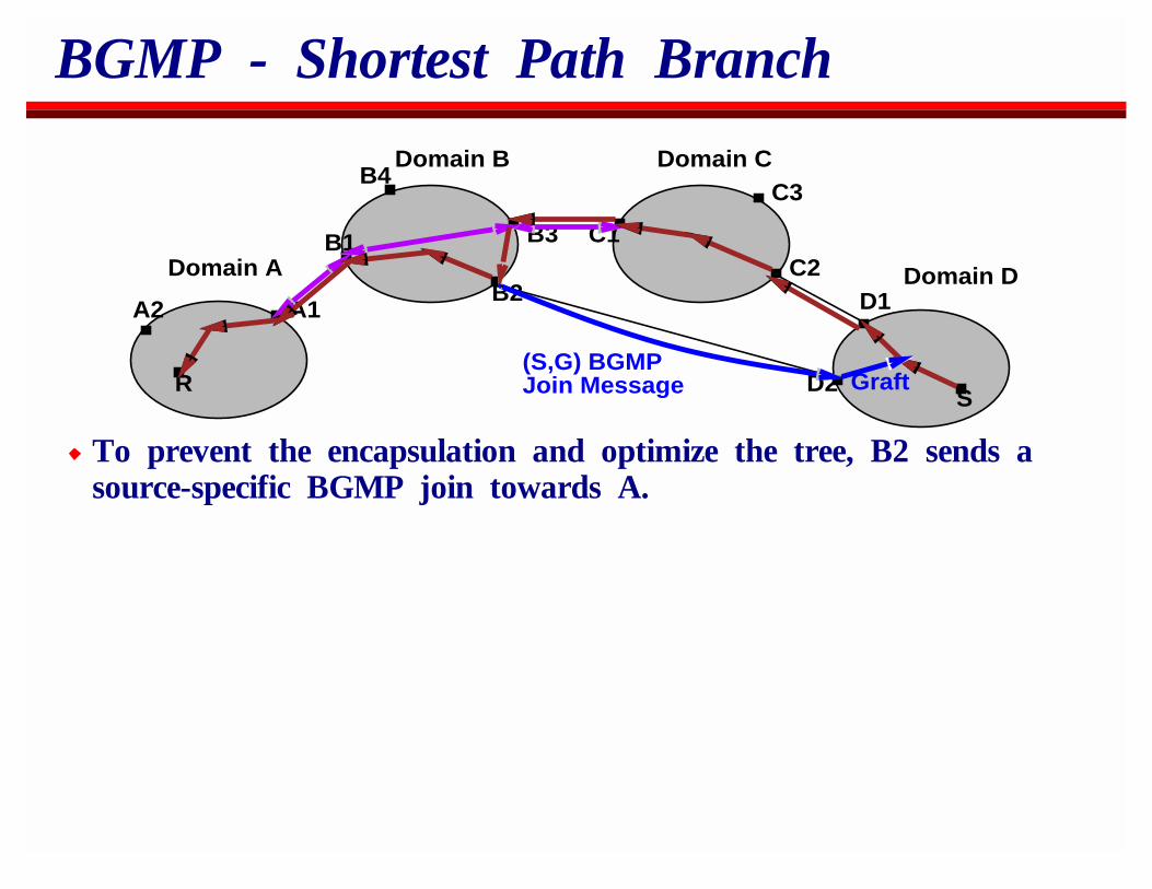
To prevent the encapsulation and optimize the tree, B2 sends asource-specific BGMP join towards A.
BGMP - Shortest Path Branch
Domain A
Domain B Domain C
RS
A1A2
B1
B2
B3B4
C1
C2
C3
D1
D2
Domain D
BGMP shared treeData packetsPIM messages
BGMPPrune
Prune
BGMP messages
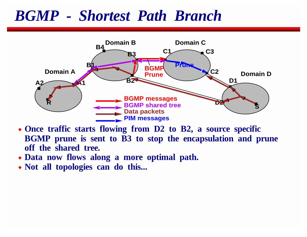
Once traffic starts flowing from D2 to B2, a source specificBGMP prune is sent to B3 to stop the encapsulation and pruneoff the shared tree.Data now flows along a more optimal path.Not all topologies can do this...
BGMP Root Domain Location
BGMP uses a hierarchical division of the multicast address spaceto know where the root domain for each address prefix islocated.This information could be statically configured, but we expect toit be generated dynamically using MASC address allocation, anddistributed to BGMP border routers using M-BGP.
For more information:BGMP and MASC Internet Drafts give protocol detailsThere’s an architecture overview paper in Sigcomm 98.
OverviewIP MulticastReal-Time Traffic on the InternetSecuritySession AnnouncementsSession InvitationH.323Multicast Address AllocationStream ControlBetter ServiceCodecs and Media PacketizationCongestion Control for Multimedia

That stack again...
IP and IP Multicast
Integrated and Differentiated Services Forwarding
UDP TCP
SAP SIP HTTP SMTP
SDP
ConferenceSetup and DIscovery
ConferenceCourse Control
RSVPDistributedControl
RTP andRTCP
ReliableMulticast
Audioand Video
SharedApplications
Conference Management Media Agents
UDPUDP
RTSP

Real-Time Traffic on the Internet
Jitter and adaptive playout bufferingRTP: IntroductionRTP: Inter-stream SynchronizationRTCP membership reportsRTCP reception feedbackIP/UDP/RTP header compression
Jitter
A−>D
Microphone
Speaker
D−>A
Depacketiser +Timing recovery +Decompression
Compression +Packetiser 1.5MBps link
20ms AudioTimeslices
Shared Link
Router
Router
Packets
Other traffic
20ms AudioTimeslices
1.5MBps link
Jitter
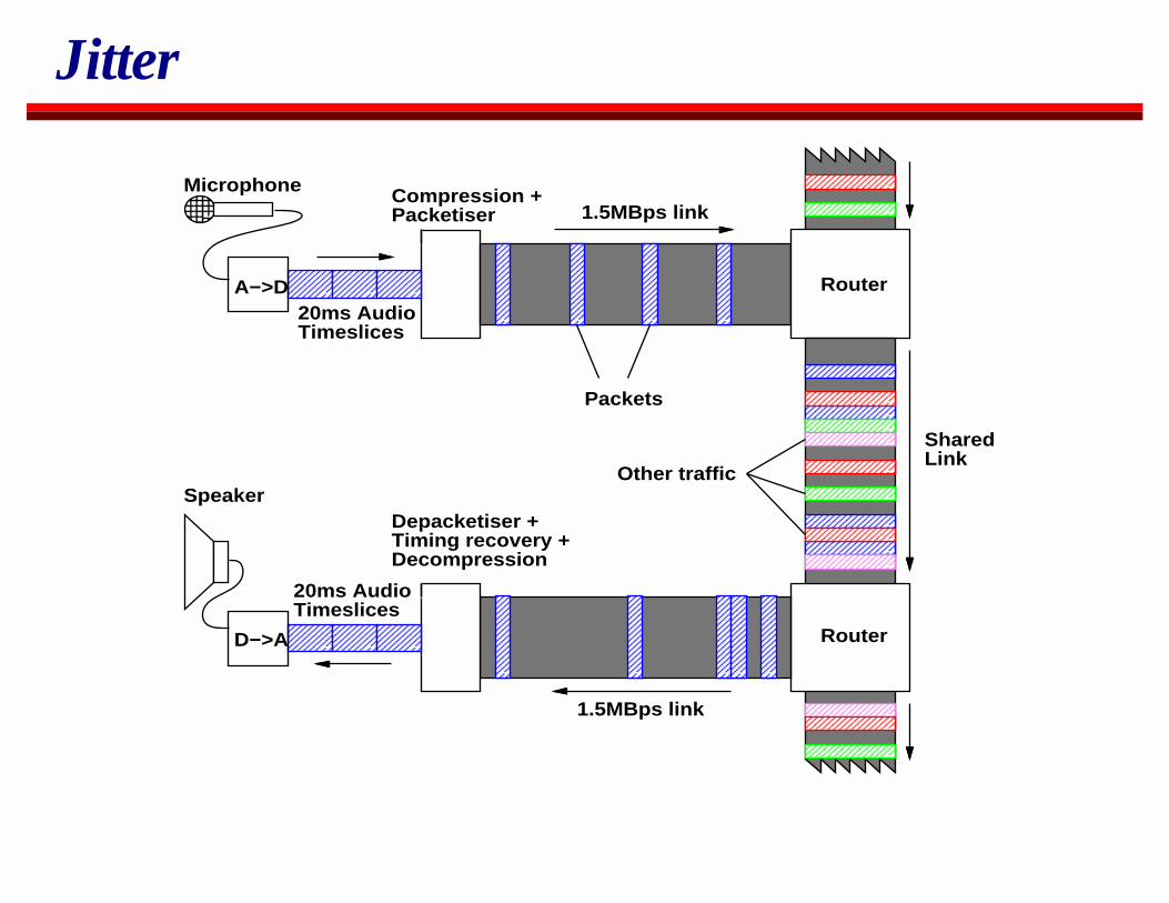
When data is sent across a shared IP network, some packets aredelayed more than others.
This occurs even when we use a reserved service - only theeffect is much reduced.
To play out the data stream at the receiver, the original timingrelationship within the media stream must be recovered.
Playout Buffering
Note: the average arrival rate at the receiver must equal thedeparture rate at the sender (otherwise the network doesn’t haveenough capacity for the data stream)As the mean rate is the same at the sender and receiver, thereceiver only has to adapt to the variance of the arrival rate.If each packet carries a sender timestamp, the receiver canreconstruct the original variance by buffering before playout.But IP doesn’t bound delay, so doesn’t this require unboundedbuffering?
Playout Buffering
Delay is bounded by queues, and so required buffering is bounded.Queue size fluctuation and thus jitter is bounded and relativelysmall.
RED queuing will help this further.Queue sizes along the path also vary and so tend to cancel eachother.
Playout Buffering
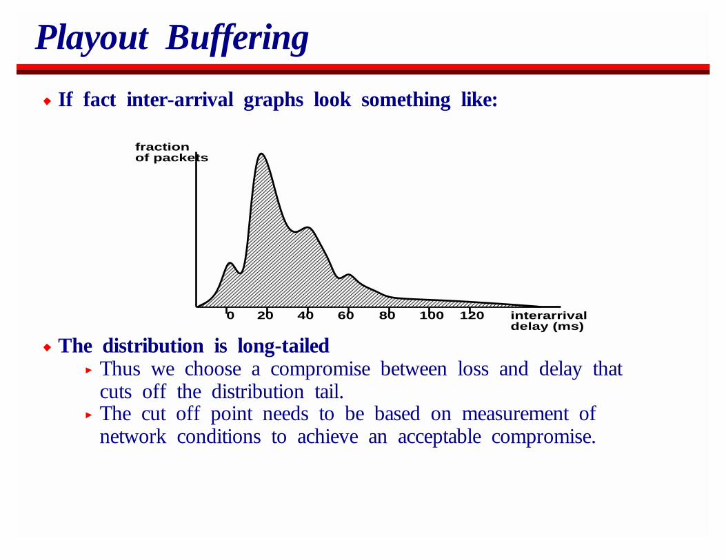
If fact inter-arrival graphs look something like:
fractionof packets
interarrival delay (ms)
0 20 40 60 80 100 120
The distribution is long-tailedThus we choose a compromise between loss and delay thatcuts off the distribution tail.The cut off point needs to be based on measurement ofnetwork conditions to achieve an acceptable compromise.
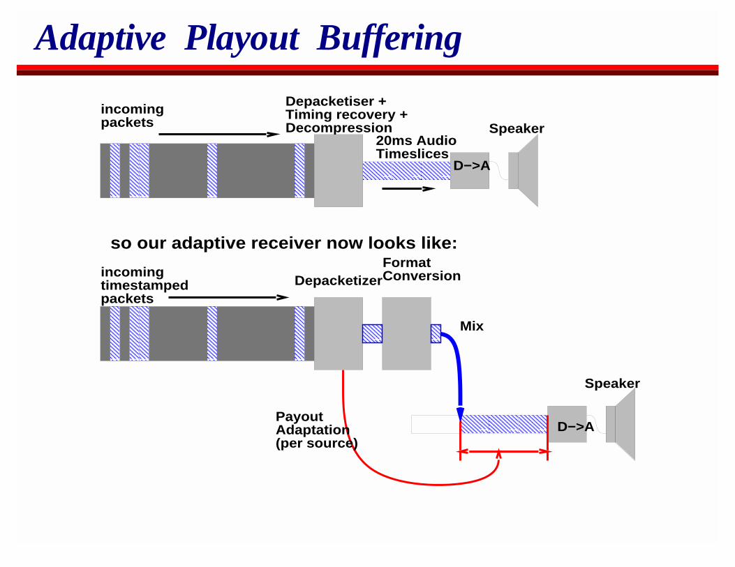
Adaptive Playout Buffering
Speaker
Depacketiser +Timing recovery +Decompression
20ms AudioTimeslices
D−>A
Speaker
D−>A
DepacketizerFormatConversion
Mix
PayoutAdaptation(per source)
incomingpackets
incomingtimestampedpackets
so our adaptive receiver now looks like:
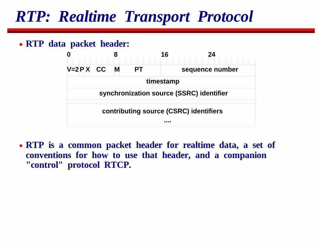
RTP: Realtime Transport Protocol
RTP data packet header:0 8 16 24
V=2P X CC M PT sequence number
timestamp
synchronization source (SSRC) identifier
contributing source (CSRC) identifiers....
RTP is a common packet header for realtime data, a set ofconventions for how to use that header, and a companion"control" protocol RTCP.
RTP: DetailsSSRC identifies a unique RTP sender.
The packet source does not identify the sender, which meansusers can move, and transcoders can be employed.If streams are mixed, CSRC identifies the source that weremixed together.
RTP: DetailsThe RTP timestamp is in units which are meaningful for themedia stream itself.
E.g., 8KHz sampled u-law audio would use an 8KHzsample-driven clock for timestamps.MPEG video would use the MPEG 90KHz clock.
This avoids having to deal with rounding when reconstructing theoriginal timing within an audio stream.However, it means the clocks for audio and video streams fromthe same source use different timebases.
RTCP relates these different clocks to realtime so A/Vsynchronization can be performed.
RTP: DetailsThe payload type field identifies the codec being used and theform of packetization.
Originally RTP allocated static payload types for codecs, butthe space is only a 7-bit space and there are too many codecs!Now, the field is mostly used with dynamic payload types.The field identifies the different codecs in a session, and anout-of-band mechanism (typically SDP) relates the PT fieldvalues to the actual codecs.
We’re also moving towards using the MIME-types registry as away to register new codec names and their RTP packetizationformats.
RTCP: Realtime Transport ControlProtocol
Each RTP session is accompanied by an RTCP control session.RTCP SDES messages are sent by all session members.
The indicate who is in the session.RTCP SR messages are sent be all data senders
They provide the relationship between media timestamps and realtime.RTCP RR messages are sent by all receivers.
They provide feedback to the senders on reception quality.These messages can be combined into compound packets.Their rate depends on the membership
The more members, the less often each reports so that thecontrol traffic is kept to a small fraction of the data bandwidth.
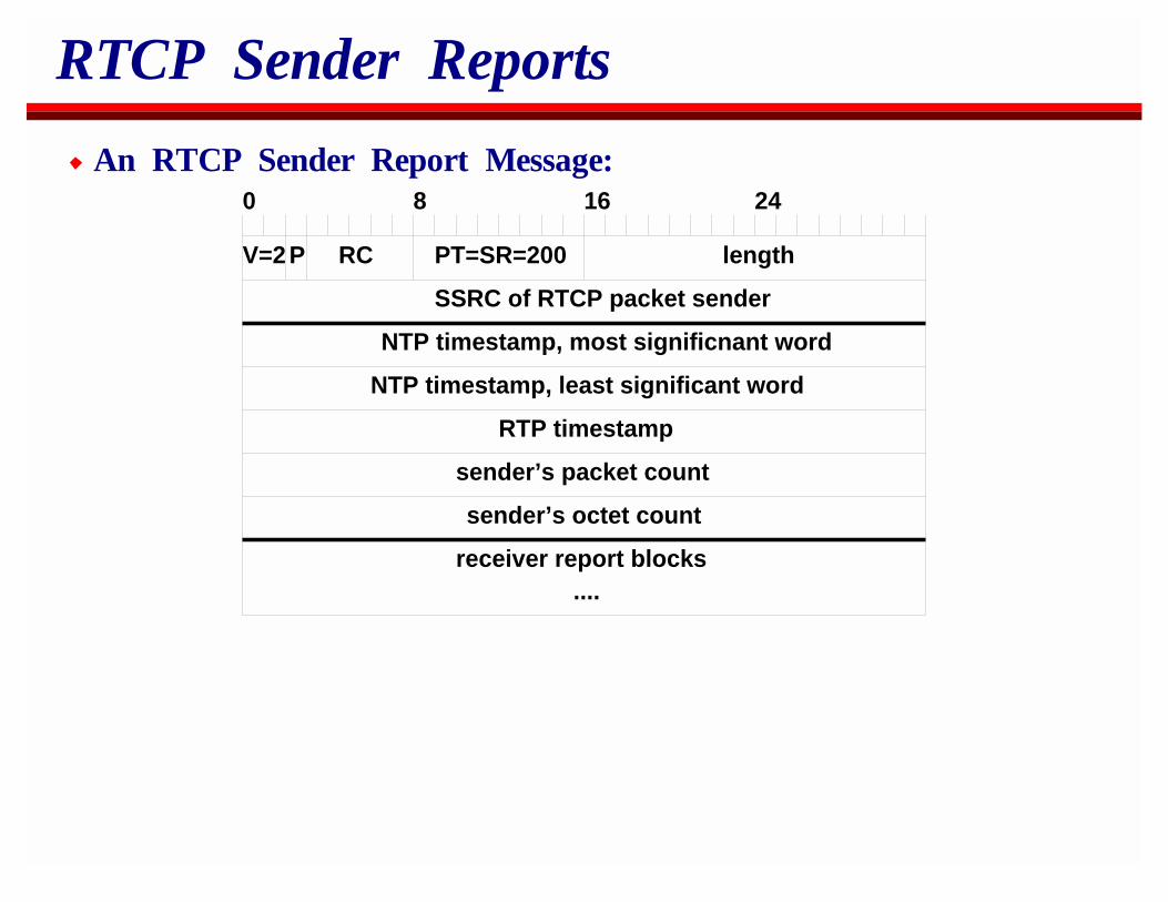
RTCP Sender Reports
An RTCP Sender Report Message:0 8 16 24
V=2P RC length
SSRC of RTCP packet sender
NTP timestamp, most significnant word
NTP timestamp, least significant word
RTP timestamp
sender’s packet count
sender’s octet count
receiver report blocks....
PT=SR=200
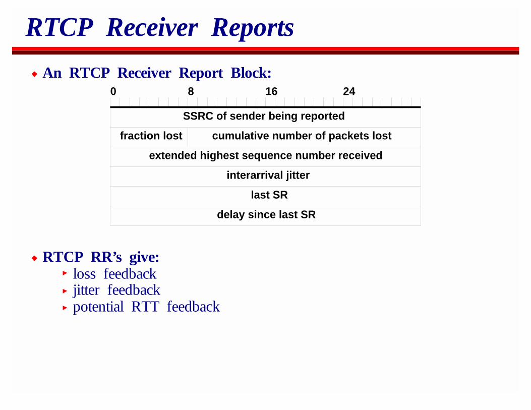
RTCP Receiver Reports
An RTCP Receiver Report Block:0 8 16 24
SSRC of sender being reported
fraction lost cumulative number of packets lost
extended highest sequence number received
interarrival jitter
delay since last SR
last SR
RTCP RR’s give:loss feedbackjitter feedbackpotential RTT feedback
RTCP Receiver Reports
Receiver reports in RTCP are a little controversialIn small sessions they definitely provide useful feedback thathelps problem diagnosis.In large sessions they provide a statistical sampling of thenetwork conditions. I believe this is very useful, but noteveryone agrees.They can be problematic when satellites with poor reverse pathproperties are used for multicast.
In addition, it’s been proposed the information be used forcongestion control.
I don’t believe RR’s are too useful for this.
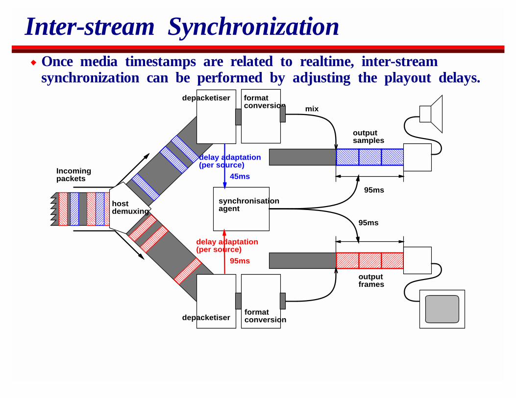
Inter-stream SynchronizationOnce media timestamps are related to realtime, inter-streamsynchronization can be performed by adjusting the playout delays.
depacketiser formatconversion mix
outputsamples
outputframes
synchronisationagent
delay adaptation(per source)
95ms
95ms
95ms
45ms
hostdemuxing
Incomingpackets
formatconversiondepacketiser
delay adaptation(per source)
RTP Overhead
The IP, UDP and RTP headers between them comprise 40 bytes.
GSM audio at 14Kbps packetized in 80ms packets occupies 140bytes per packet. Thus the headers add an extra ~30%.
There are lower bandwidth codecs than GSM for which this iseven worse.Also for better interactivity, perhaps 40ms packets would bedesirable with some codecs?
On low bandwidth links, perhaps RTP is too expensive?
IP/UDP/RTP Header Compression
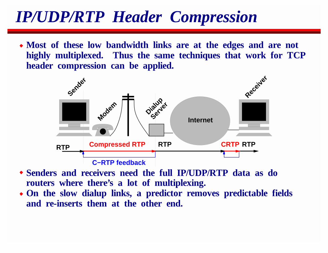
Most of these low bandwidth links are at the edges and are nothighly multiplexed. Thus the same techniques that work for TCPheader compression can be applied.
Internet
Sender
Modem Dialup
Serve
r
Receiv
er
RTP Compressed RTP
C−RTP feedback
RTP RTPCRTP
Senders and receivers need the full IP/UDP/RTP data as dorouters where there’s a lot of multiplexing.On the slow dialup links, a predictor removes predictable fieldsand re-inserts them at the other end.
IP/UDP/RTP Header Compression
RTP header compression compresses the IP, UDP and RTPheaders down to a few bytes.
This possible because most of the headers either do notchange between one packet and the next or change in apredictable manner.The link-sender removes the predictable state, and thelink-receiver holds per-flow state and adds it back.
A gateway cannot tell whether UDP is carrying RTPThe scheme is designed to compress IP and UDP if RTP isnot being used, and compress the RTP header too if it turnsout to be predictable.
OverviewIP MulticastReal-Time Traffic on the InternetSecuritySession AnnouncementsSession InvitationH.323Multicast Address AllocationStream ControlBetter ServiceCodecs and Media PacketizationCongestion Control for Multimedia
SecurityEncryption of StreamsMulticast ScopingKey ManagementFirewallsOpen Issues
Encryption of Streams
Encryption is the primary means of ensuring confidentiality inmulticast (or unicast) sessions.
You can never be certain that your packets won’t be observedby someone.This is especially so with multicast.
For many purposes, private key encryption of the data streams issufficient.
RTP specifies how to do this.Session set-up mechanisms such as SIP can convey the sessionkeys.
Multicast Scoping
Multicast scope zones can be configured.The border routers to a region can be configured to not passa range of multicast addresses into or out of the region.Applications using these addresses within the region areprotected from bad guys outside.They have some measure of assurance where their traffic willgo.
This is only as good as the configuration of the boundary, and isvulnerable to defeat by bad guys inside the zone who could relaytraffic to/from another group.
Not a substitute for encryption, but a useful additionalmechanism.
Problems
So which problems are not solved yet?Key ManagementFirewallsChanging MembershipAssured data sources
Key Management
This is the number one security problem.When (if?) a public key infrastructure exists, Internet multimediaapplications will be able to make good use of it.
SIP can use public keys for secure invitations which carryprivate session keysSAP can use public keys by pre-distributing SAP public orprivate keys to intended members of private groups usingS/MIME mail.Both SIP and SAP can use public keys for authentication ofmessage originators.
But right now, there’s no widely used infrastructure we canleverage.
PGP is most widely used, and is specified in the SIP andSAP specs as a recommended mechanism.
Firewalls
In corporate networks, firewalls pose a significant deploymentproblem.
Firewalls are often intended only for TCP and DNS.Multicast is simply blocked.UDP is simply blocked.
There needs to be a way to open authorized holes in the firewallfor unicast and multicast UDP.
SIP is pretty good at this as it was designed with this in mind.H.323 is not great, but the Gatekeeper can control the firewallif the request itself is allowed inside.SAP is not good in this context. Passing SAP is safe, butthere needs to be a way to request the firewall opens a holefor the session itself.
Perhaps firewall aware clients can use SIP for this?
Changing Membership
If a group of people are having a multicast conference, and wishto admit a new member, the session key must be changed.
He may have recorded the session prior to joining.Similarly for excluding an existing member.
If the session is small, an existing member can communicate thenew key pairwise to the other members.
Currently there’s no recommended way to do this, althoughSIP would work well.
If the session is large, changing keys like this doesn’t scale well.This is similar to per-per-view with cable TV but without thecontrol of the distribution infrastructure.Probably it’s best solved by receiver requests to replicatedRTSP servers.
Are there any sessions in the middle ground?
Assured Data Sources
CNN decides to use the Internet for distribution.How do they prevent someone else sending to their viewerspretending to be CNN?Private key encryption doesn’t work because anyone who canreceive can send.Signing every data packet (MD5 hash + public keyencryption) would work, only it’s probably too slow.
If we can tolerate a little delay, encrypt each one second block ofpackets with a different private key. Say 5 seconds later, send asigned packet containing the private key and how long agoreceivers must have received the packets using this key. Sendthis signature multiple times to ensure it’s received.
There’s no standard for doing this yet, but it should work.Man-in-the-middle attacks are possible without clock-sync.
OverviewIP MulticastReal-Time Traffic on the InternetSecuritySession AnnouncementsSession InvitationH.323Multicast Address AllocationStream ControlBetter ServiceCodecs and Media PacketizationCongestion Control for Multimedia
That stack again...
IP and IP Multicast
Integrated and Differentiated Services Forwarding
UDP TCP
SAP SIP HTTP SMTP
SDP
ConferenceSetup and DIscovery
ConferenceCourse Control
RSVPDistributedControl
RTP andRTCP
ReliableMulticast
Audioand Video
SharedApplications
Conference Management Media Agents
UDPUDP
RTSP
Session AnnouncementsSession Description ProtocolSession Announcement ProtocolThe Future of SAP
Session Description Protocol (SDP)
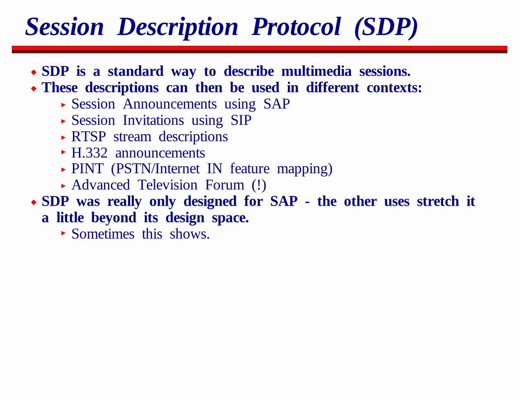
SDP is a standard way to describe multimedia sessions.These descriptions can then be used in different contexts:
Session Announcements using SAPSession Invitations using SIPRTSP stream descriptionsH.332 announcementsPINT (PSTN/Internet IN feature mapping)Advanced Television Forum (!)
SDP was really only designed for SAP - the other uses stretch ita little beyond its design space.
Sometimes this shows.
SDP
SDP is a text-based description format.It is extensible through attributes (which don’t have to beregistered) and by several other name-spaces that are registeredwith IANA.
It was not intended for content negotiation.SIP can use it for this purpose, but it’s not as elegant as ifSDP had been designed for this.
SDP
It was intended for announcing the existence of sessions. Itconveys:
Information to allow you to choose whether to join the session.Session timing informationInformation to inform you of the resources required toparticipate.Sufficient information to allow you to join the session
protocols and codec formatsmulticast addresses and portsencryption keys
Information that RTP needs passed out-of-band.
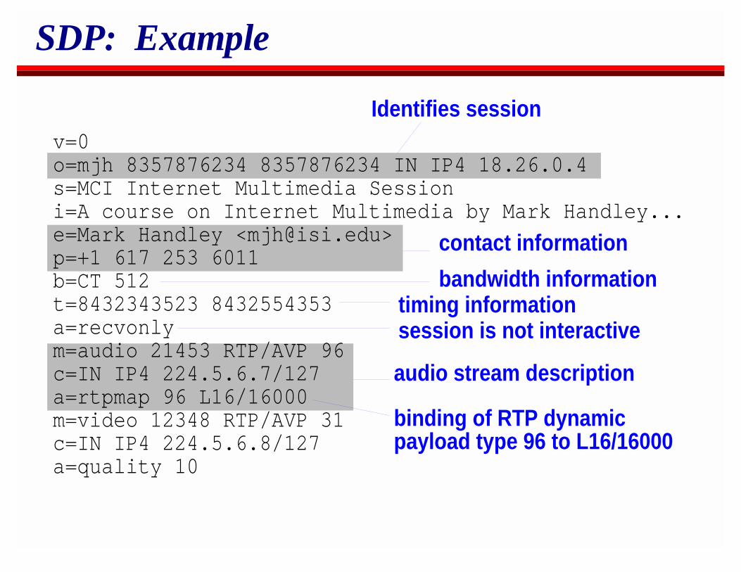
SDP: Example
Identifies session
timing information
v=0o=mjh 8357876234 8357876234 IN IP4 18.26.0.4s=MCI Internet Multimedia Sessioni=A course on Internet Multimedia by Mark Handley...e=Mark Handley <[email protected]>p=+1 617 253 6011b=CT 512t=8432343523 8432554353a=recvonlym=audio 21453 RTP/AVP 96c=IN IP4 224.5.6.7/127a=rtpmap 96 L16/16000m=video 12348 RTP/AVP 31c=IN IP4 224.5.6.8/127a=quality 10
audio stream description
contact information
bandwidth information
session is not interactive
binding of RTP dynamicpayload type 96 to L16/16000
Session Announcement Protocol (SAP)
SAP is a very simple announcement protocol for conveyinginformation about sessions to potential listeners.
Receivers simply listen to a well known multicast group.Senders periodically send announcements to that group.
The rate of transmission depends on the number of announcementsTypically each announcement will be repeated every fewminutes.The intention was always to have local caches so a sessiondirectory tool starting up doesn’t have to wait for manyminutes.
SAP Scaling
SAP effectively provides a TV-Guide style session directory.Its scaling is independent of the number of receivers, butlinear with number of announcements.
If it is only used session announcements of general interest, thismight be OK for a little while.
Currently many announced sessions are small private ones.This cannot continue for long.
Two problems:Discovering the sessions you’re interested in.Interval between announcements becoming too long.
SAP: Discovering Sessions
If several thousand sessions are being announced, it becomesimpossible to discover interesting sessions.SDP has attributes to help this:
Category attributeKeywords attributeSession Type attribute
No-one sets category or keywords. We’re just starting to filter ontype which is set by sdr and IP/TV.
SAP: Announcement Interval
With SAP bandwidth fixed, the more sessions, the longer betweenthe announcements.
Without sufficient announcements per session, SAP becomesunreliable, even with local caching.
We knew this from the outset, but flat-SAP is such a useful Mbonebootstrap mechanism we’re ignoring it until it becomes an issue.
Several possibilities exists to solve the problem:Increase the bandwidthMultiple announcement directories organized by categoryReplace SAP with something topologically hierarchical
SAP: Multiple Announcement Directories
The "root" SAP group only carries SDP announcements for otherSAP "directories".
Each of these directories can carry announcements for sessions,or for further directories.The result is either a tree or a graph of links, similar to aweb of announcement sessions rather than HTML pages.Each directory carries session announcements for one subject.Each directory has its own SAP bandwidth allocation. Thebackbone carries all directories but the leaves only carry theones requested.
The existing SAP spec allows this.
SAP: Multiple Announcement Directories
Problem: Interaction with caching.We still can’t send often enough to give fast response whensomeone joins a directory.Caches then draw unneeded announcement groups in casesomeone needs them.
Next-generation SAP?
Some Reliable Multicast work looks promising here.Multiple announcement groups really needs a protocol wherethe receivers can be active.Work on scalable SRM session messages suggests hierarchicallysubdividing the receivers by location, having arearepresentatives.
On joining a directory, a receiver does a form of expanding ringsearch to find someone who already is up-to-date.New announcements are sent to the whole group, but not sentperiodically.Summarization messages give sufficient information to discoverymissing announcements rapidly and a similar expanding ringmechanism is used to elicit retransmission.
OverviewIP MulticastReal-Time Traffic on the InternetSecuritySession AnnouncementsSession InvitationH.323Multicast Address AllocationStream ControlBetter ServiceCodecs and Media PacketizationCongestion Control for Multimedia

Session InvitationThe User Mobility ProblemSIP MechanismsSIP Security
SIP: History
Early session initiation protocols:ivsd (Turletti, INRIA)mmcc (Schooler, ISI)
These led eventually to SIPv1 (Handley and Schooler) which wasintended to initiate loosely coupled sessions.
SIP stopped when the session startedUDP based
Henning Schulzrinne designed SCIP using RTSP as a basisaround the same time.
TCP basedContinued during the call
Eventually we merged SIPv1 and SCIP into SIPv2best features of both, UDP and TCP
H.323 was also being drafted at the same time
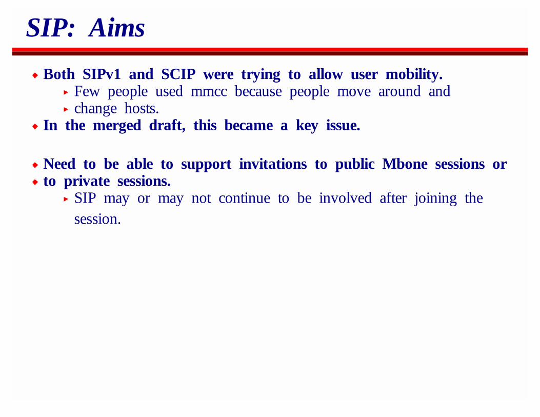
SIP: Aims
Both SIPv1 and SCIP were trying to allow user mobility.Few people used mmcc because people move around andchange hosts.
In the merged draft, this became a key issue.
Need to be able to support invitations to public Mbone sessions orto private sessions.
SIP may or may not continue to be involved after joining thesession.
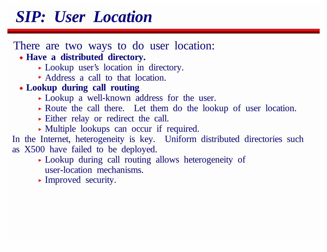
SIP: User Location
There are two ways to do user location:Have a distributed directory.
Lookup user’s location in directory.Address a call to that location.
Lookup during call routingLookup a well-known address for the user.Route the call there. Let them do the lookup of user location.Either relay or redirect the call.Multiple lookups can occur if required.
In the Internet, heterogeneity is key. Uniform distributed directories suchas X500 have failed to be deployed.
Lookup during call routing allows heterogeneity ofuser-location mechanisms.Improved security.
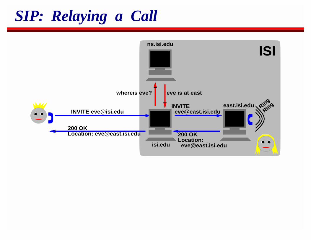
SIP: Relaying a Call
east.isi.edu Ring
Ring
isi.edu
ns.isi.edu
INVITE [email protected]
whereis eve? eve is at east
ISI
200 OKLocation: [email protected]
200 OKLocation: [email protected]
INVITE [email protected]
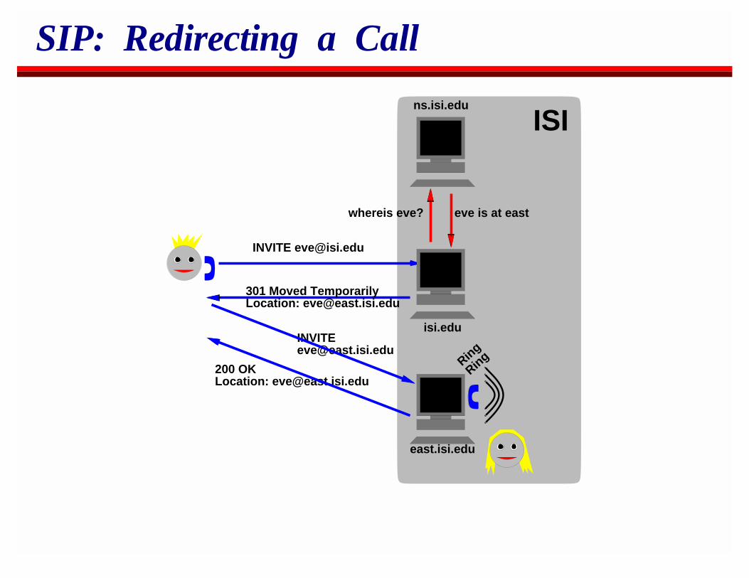
SIP: Redirecting a Call
Ring
Ring
isi.edu
ns.isi.edu
INVITE [email protected]
whereis eve? eve is at east
200 OKLocation: [email protected]
INVITE [email protected]
east.isi.edu
ISI
301 Moved TemporarilyLocation: [email protected]
SIP Proxies
SIP proxies can use any reasonable search algorithmSend requests in parallelSend requests sequentially
Normally only a proxy close to the callee can decide on anappropriate search strategy.SIP specifies only the rules that proxies must use to combineresponses when multiple requests are made in parallel.
A standard way to specify proxy call processing rules is desirable,but SIP itself doesn’t care how the processing is performed.
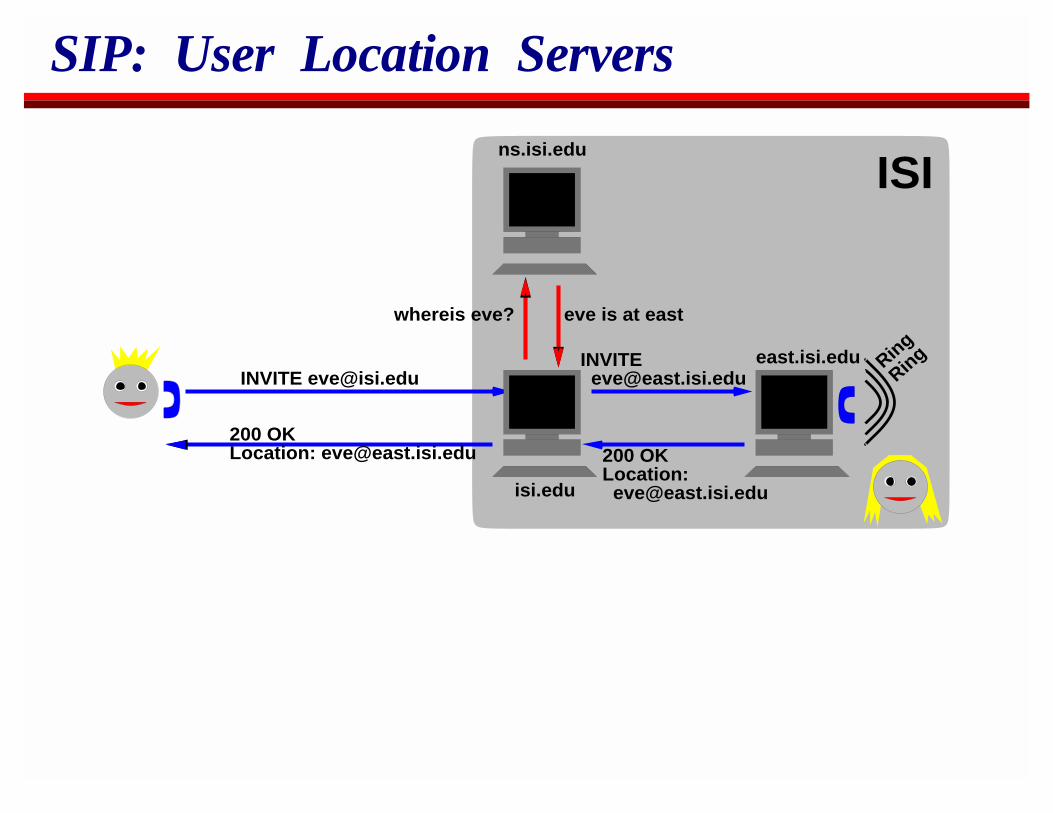
SIP: User Location Servers
east.isi.edu Ring
Ring
isi.edu
ns.isi.edu
INVITE [email protected]
whereis eve? eve is at east
ISI
200 OKLocation: [email protected]
200 OKLocation: [email protected]
INVITE [email protected]
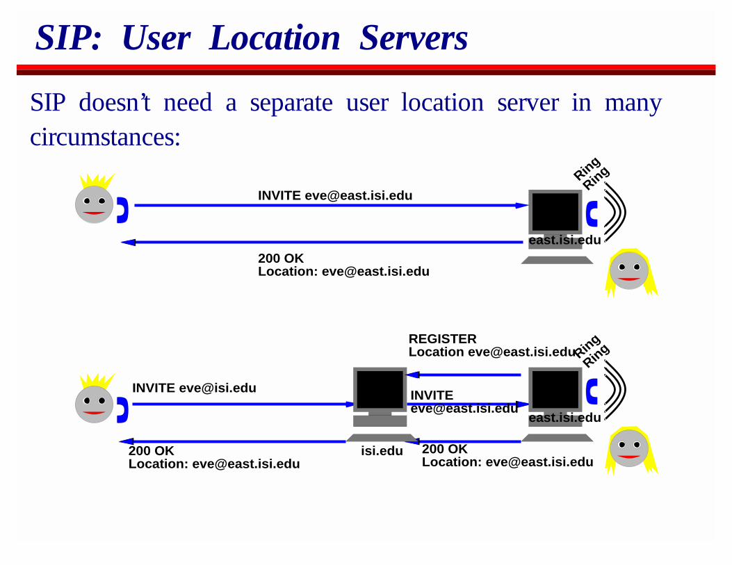
SIP: User Location Servers
SIP doesn’t need a separate user location server in manycircumstances:
Ring
Ring
200 OKLocation: [email protected]
east.isi.edu
INVITE [email protected]
Ring
Ring
isi.edu
INVITE [email protected]
200 OKLocation: [email protected]
INVITE [email protected]
east.isi.edu
200 OKLocation: [email protected]
REGISTERLocation [email protected]
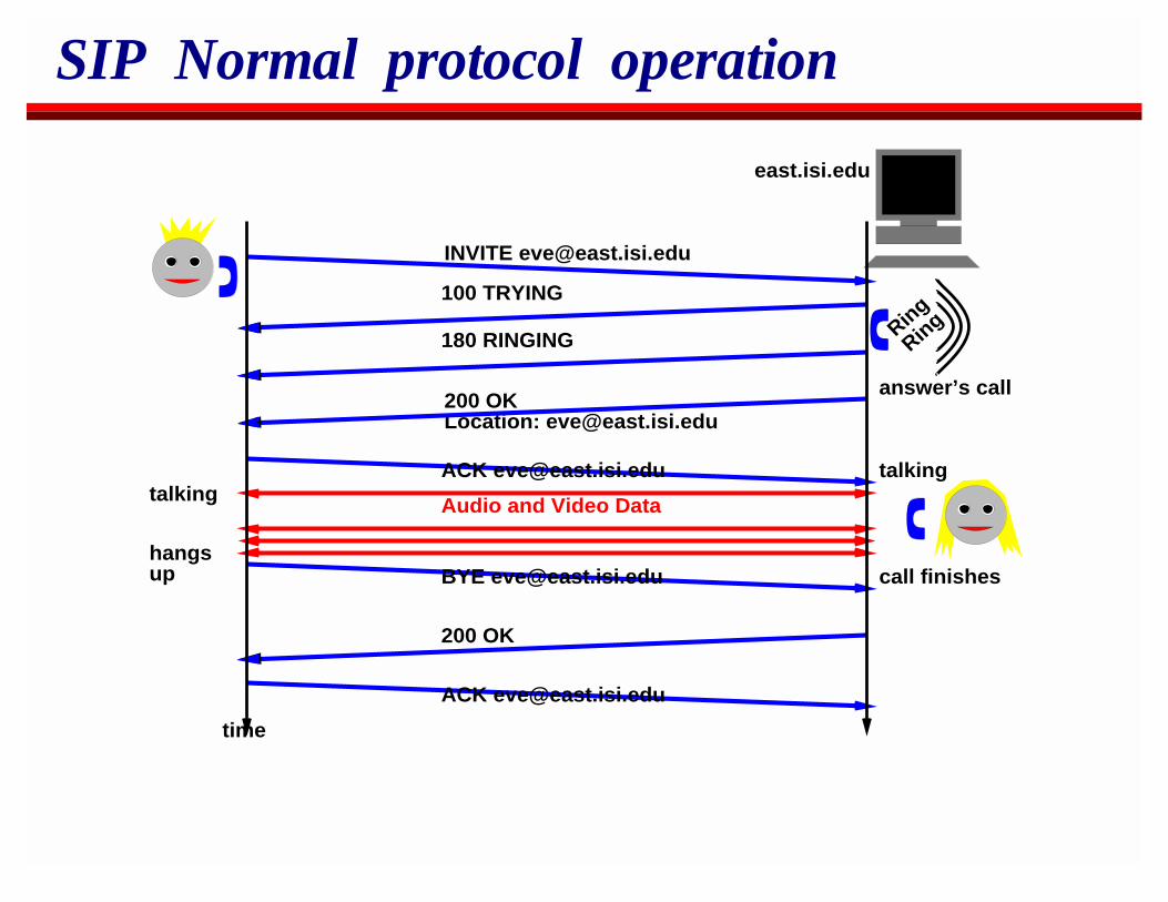
SIP Normal protocol operation
Ring
Ring
200 OKLocation: [email protected]
east.isi.edu
180 RINGING
100 TRYING
INVITE [email protected]
Audio and Video Data
200 OK
time
talkingtalking
hangsup call finishes
answer’s call
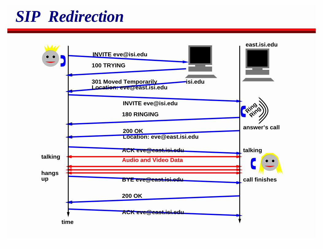
SIP Redirection
Ring
Ring
200 OKLocation: [email protected]
east.isi.edu
180 RINGING
100 TRYING
Audio and Video Data
200 OK
time
talkingtalking
hangsup call finishes
answer’s call
INVITE [email protected]
INVITE [email protected]
isi.edu301 Moved TemporarilyLocation: [email protected]
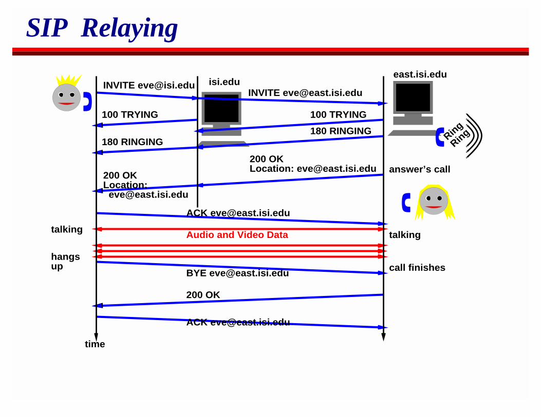
SIP Relaying
Ring
Ring
east.isi.edu
180 RINGING
100 TRYING
Audio and Video Data
200 OK
time
talkingtalking
hangsup call finishes
answer’s call
INVITE [email protected] isi.edu
200 OKLocation: [email protected]
INVITE [email protected]
100 TRYING
180 RINGING
200 OKLocation: [email protected]
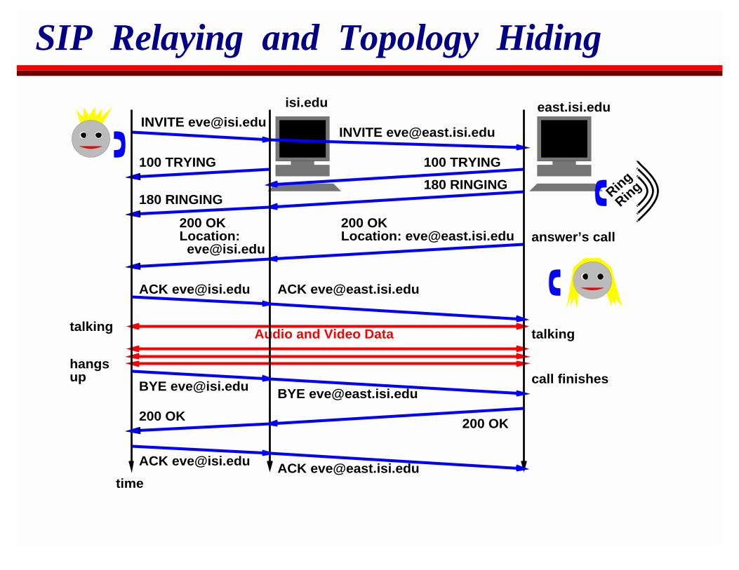
SIP Relaying and Topology Hiding
Ring
Ring
east.isi.edu
180 RINGING
100 TRYING
Audio and Video Data
200 OK
talkingtalking
hangsup call finishes
answer’s call
INVITE [email protected]
isi.edu
200 OKLocation: [email protected]
INVITE [email protected]
100 TRYING
180 RINGING
200 OKLocation: [email protected]
200 OK
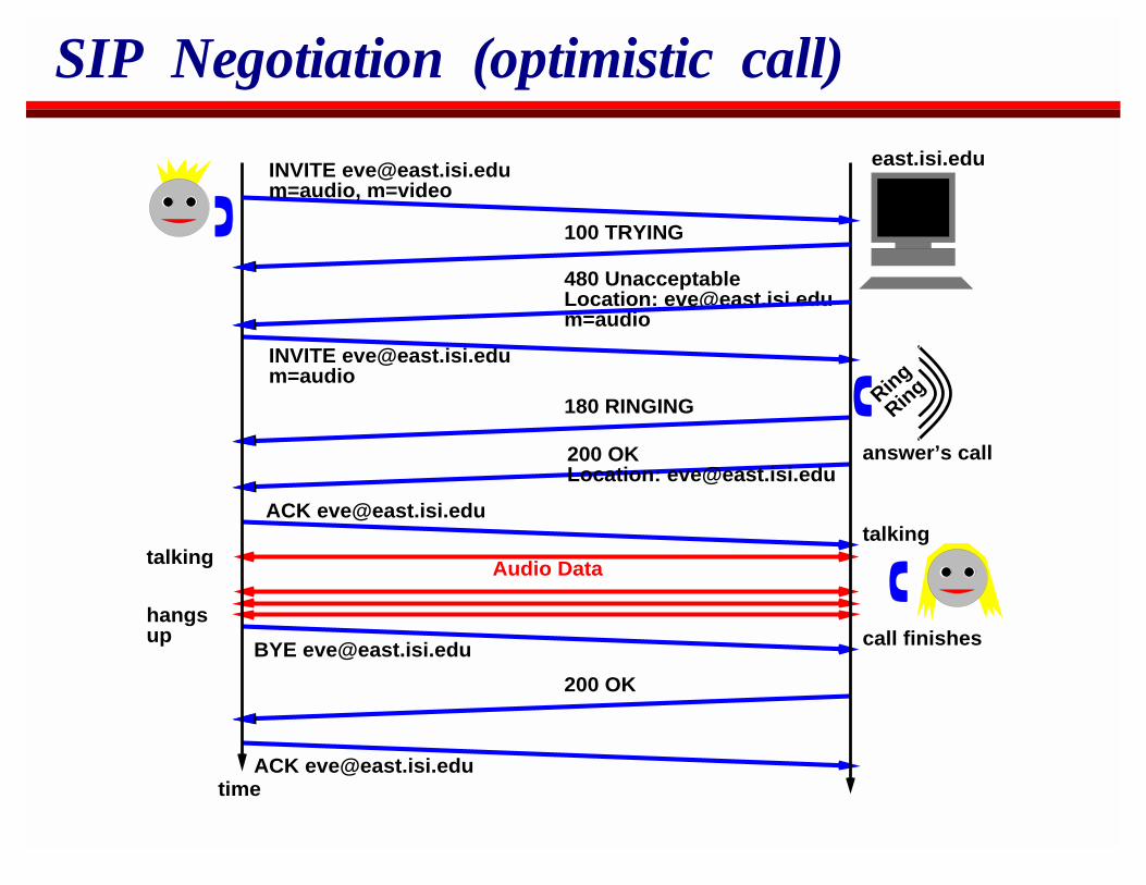
SIP Negotiation (optimistic call)
Ring
Ring
east.isi.edu
100 TRYING
200 OK
talkingtalking
hangsup call finishes
answer’s call
480 UnacceptableLocation: [email protected]=audio
INVITE [email protected]=audio
180 RINGING
INVITE [email protected]=audio, m=video
Audio Data
200 OKLocation: [email protected]
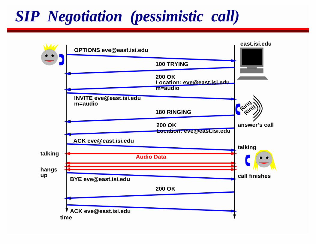
SIP Negotiation (pessimistic call)
Ring
Ring
east.isi.edu
100 TRYING
200 OK
talkingtalking
hangsup call finishes
answer’s call
INVITE [email protected]=audio
180 RINGING
Audio Data
OPTIONS [email protected]
200 OKLocation: [email protected]=audio
200 OKLocation: [email protected]
SIP Syntax
SIP is a text based protocol, similar in syntax to HTTP andRTSP.Messages can be conveyed over UDP or TCP.
SIP provides its own reliability over UDP.UDP is preferred - it gives more control over message timing,and requires less state in proxies.TCP is allowed for legacy firewall traversal but in time wehope firewalls themselves will support SIP.
Typically SIP carries an SDP session description as a payload todescribe the session being initiated.
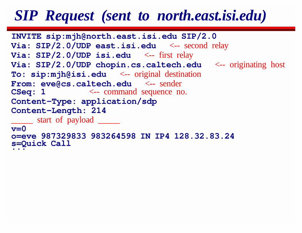
SIP Request (sent to north.east.isi.edu)INVITE sip:[email protected] SIP/2.0Via: SIP/2.0/UDP east.isi.edu <-- second relayVia: SIP/2.0/UDP isi.edu <-- first relayVia: SIP/2.0/UDP chopin.cs.caltech.edu <-- originating hostTo: sip:[email protected] <-- original destinationFrom: [email protected] <-- senderCSeq: 1 <-- command sequence no.Content-Type: application/sdpContent-Length: 214_____ start of payload _____v=0o=eve 987329833 983264598 IN IP4 128.32.83.24s=Quick Call...
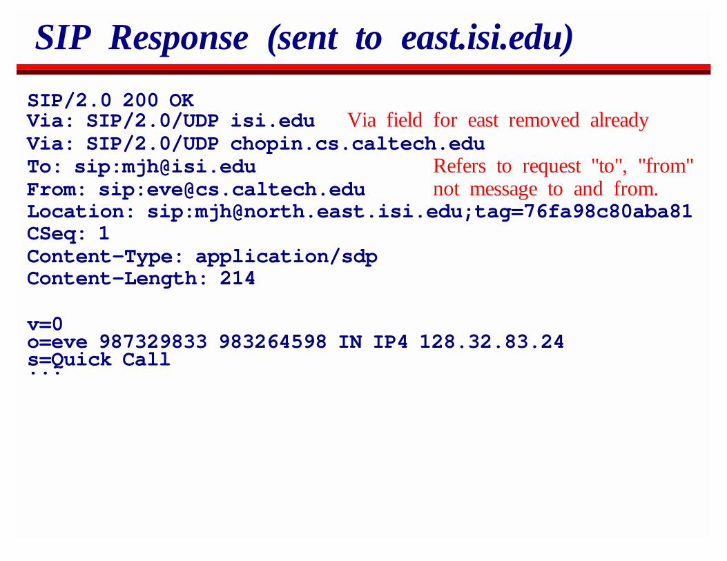
SIP Response (sent to east.isi.edu)
SIP/2.0 200 OKVia: SIP/2.0/UDP isi.edu Via field for east removed alreadyVia: SIP/2.0/UDP chopin.cs.caltech.eduTo: sip:[email protected] Refers to request "to", "from"From: sip:[email protected] not message to and from.Location: sip:[email protected];tag=76fa98c80aba81CSeq: 1Content-Type: application/sdpContent-Length: 214
v=0o=eve 987329833 983264598 IN IP4 128.32.83.24s=Quick Call...
SIP Searching
A SIP client or proxy can route a request to many servers inparallel.
All the "telephones" will ring simultaneously.Typically the first to answer will be the one that is connected.
SIP is intended for personal mobility - normally you’re only inone place at once.If you want your secretary to answer, don’t arrange for aparallel search!
Other responses ("Not known", "Not currently here"), etc willalso be generated.
SIP search rules mean that definitive responses ("OK","Decline", "Doesnt exist anywhere") suppress non-definitive ones.
After a definitive response, other branches of the search tree andcanceled using the CANCEL method.
SIP Security
SIP was designed from the outset with security in mind.SIP requests can be encrypted and/or authenticated end-to-endusing public-key encryption.
To, From, Via headers still in the clear.SIP requests can be encrypted hop-by-hop to protect againstpacket sniffing.
Also anonymized From and To headers can be used in theexternal header with the correct headers encrypted end-to-end.
Via fields record the route of the request.They’re removed on the return path so a caller can’t obtaintopology information.They can be hidden on the forward path so the caller’stopology information can also be withheld.
OverviewIP MulticastReal-Time Traffic on the InternetSecuritySession AnnouncementsSession InvitationH.323Multicast Address AllocationStream ControlBetter ServiceCodecs and Media PacketizationCongestion Control for Multimedia
H.323
In 1988 the ITU defined H.320 for ISDN videotelephony overbasic-rate ISDN.H.320 was always meant to be part of a compatible family ofprotocols:
H.324 for videotelephony over POTSH.321 for videotelephony over ATMH.323 for videotelephony over Ethernet ("non QOS packetnetworks")
H.320 was designed by telephony people with telephones in mind.It can even interoperate with 56/64Kbps PCM without thePCM telephone realizing!H.323 was heavily influenced by H.320 design decisions.
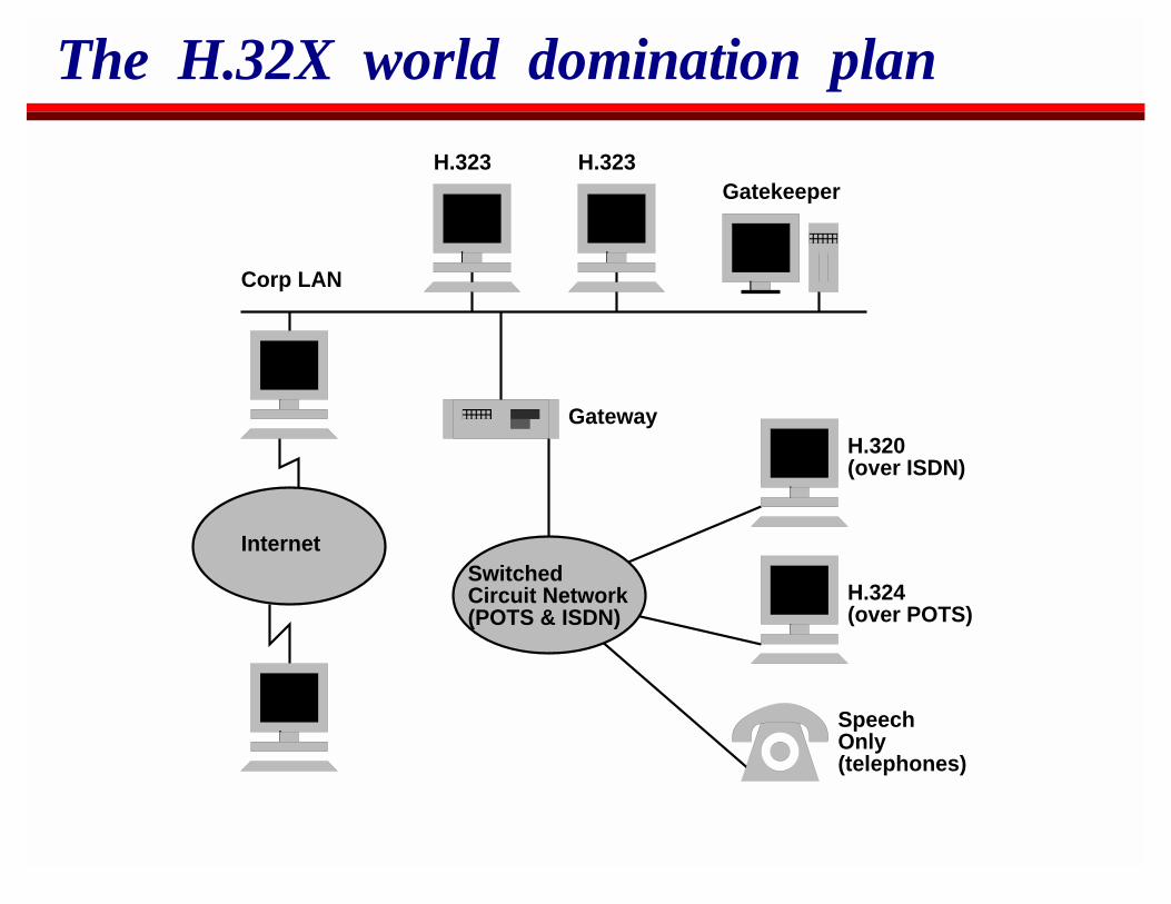
The H.32X world domination plan
Internet
Corp LAN
H.323 H.323Gatekeeper
H.320(over ISDN)
H.324 (over POTS)
SpeechOnly(telephones)
SwitchedCircuit Network(POTS & ISDN)
Gateway
H.323 on the Internet
H.323 was designed for corporate LANs.The gatekeeper has control over who does what.
After H.323 was finalized, a subset of it was defined for pureInternet use.
Gatekeeper no longer required.
H.323 Protocol Components
Core componentsQ.931 over TCP for initial call setupH.245 for capabilities negotiationH.225.0 for logical connection establishmentRTP for media transport
Additional ComponentsH.332 for large conferencesH.450.1, H.450.2, H.450.3 for supplementary servicesH.235 for securityH.246 for interoperability with circuit switched networks
H.323 version 1 call setup
In the original H.323 call setup consisted of:Q.931 call signaling (1st TCP connection)H.245 capability exchange (2nd TCP connection)H.225.0 establish logical channels (3rd TCP connection)Now send RTP...
Each TCP connection requires a SYN exchange before data canbe sent, plus the usual TCP timeouts on packet loss.
Connection setup was excessively slow.
H.323 evolution
H.323 has evolved so that many of the original defects have beenreduced.
Unfortunately you still need to implement the old mechanismstoo to be compliant.
Two new methods of setup:H.245 tunneling over the H.225.0 connection.H.323v2 FastStart
H.323 FastStart
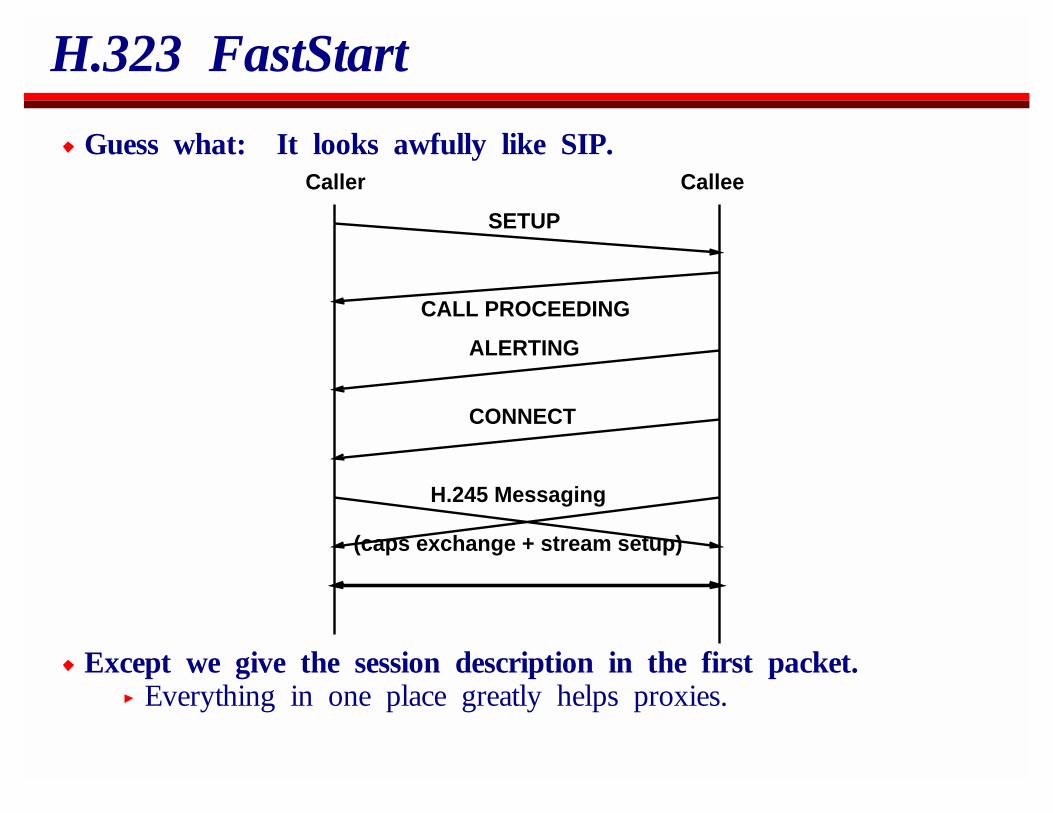
Guess what: It looks awfully like SIP.
SETUP
CALL PROCEEDING
ALERTING
CONNECT
H.245 Messaging
(caps exchange + stream setup)
Caller Callee
Except we give the session description in the first packet.Everything in one place greatly helps proxies.
SIP vs H.323
H.323 uses TCP for setupUDP gives better timing controlUDP is critical for very large proxies that wish to be stateless.
H.323 uses ASN.1 Packed Encoding RulesFor a long time only one company sold an ASN.1 compilerthat could compile H.323’s ASN.1
SIP uses an HTTP-like syntax.Much easier to write and to debug.Much experience with HTTP
The H.323 base specs run to approximately 750 pages.
SIP vs H.323
H.323 provides floor control within a session.SIP can signal that a conference control protocol is to beused, but doesn’t provide the functionality itself.There’s a proposal for a Simple Conference Control Protocol(SCCP) that might do this.It’s not terrible clear how often this functionality is reallyneeded - Mbone conferences work fine without it.
H.323 provides a multipoint controllerNot needed for SIP multicast conferencesSimple MC control could trivially be specified in SIP ifrequired, but currently this is not specified.
SIP vs H.323
SIP is more extensible.Any codecs can be registered for use over RTP.H.323 can only use registered codecs that have code pointsassigned.SIP Requires header code allows extension negotiation.H.323 can only be extended in certain places. No extensionnegotiation.Unknown SIP response codes can be handled correctly basedpurely on the response code category
SIP vs H.323SIP was designed with proxies in mind.
User Location takes advantage of heterogeneity.Topology and information hiding.
SIP was designed with security in mind.H.323 attempts to bolt this on because it was designed forcorporate LANs.
SIPBut then I’m not exactly impartial :-)
OverviewIP MulticastReal-Time Traffic on the InternetSecuritySession AnnouncementsSession InvitationH.323Multicast Address AllocationStream ControlBetter ServiceCodecs and Media PacketizationCongestion Control for Multimedia
Multicast Address AllocationArchitecture OverviewMDHCPAAPMASC (and its relation to BGMP)
Multicast Address Allocation
Note:This is work-in-progress. There’s no guarantee this will be deployedas described here, but currently it’s the only proposal for theexisting service model.
Goal of this work
To produce an architecture for multicast address allocation forthe global Internet.Requirements:
Allocate addresses on demand with very high serviceavailability.Minimise probability of address allocation clashes.Maximise usage of the limited address space.Allocate addresses in a manner that aids scalable multicastrouting.
Why not guarantee uniqueness?
We do not believe we can guarantee uniqueness and satisfy theother requirements.
Architectures that guarantee uniqueness fail to deliver on eitherservice availability or address space packing or both.
We do not believe it is necessary to guarantee unique allocation.We cannot stop people just using addresses without using theallocation architecture.IGMPv3 source specific pruning combined with simple hostchanges may be able to relieve address clashes on the rareoccasions they do occur.
Architecture Overview
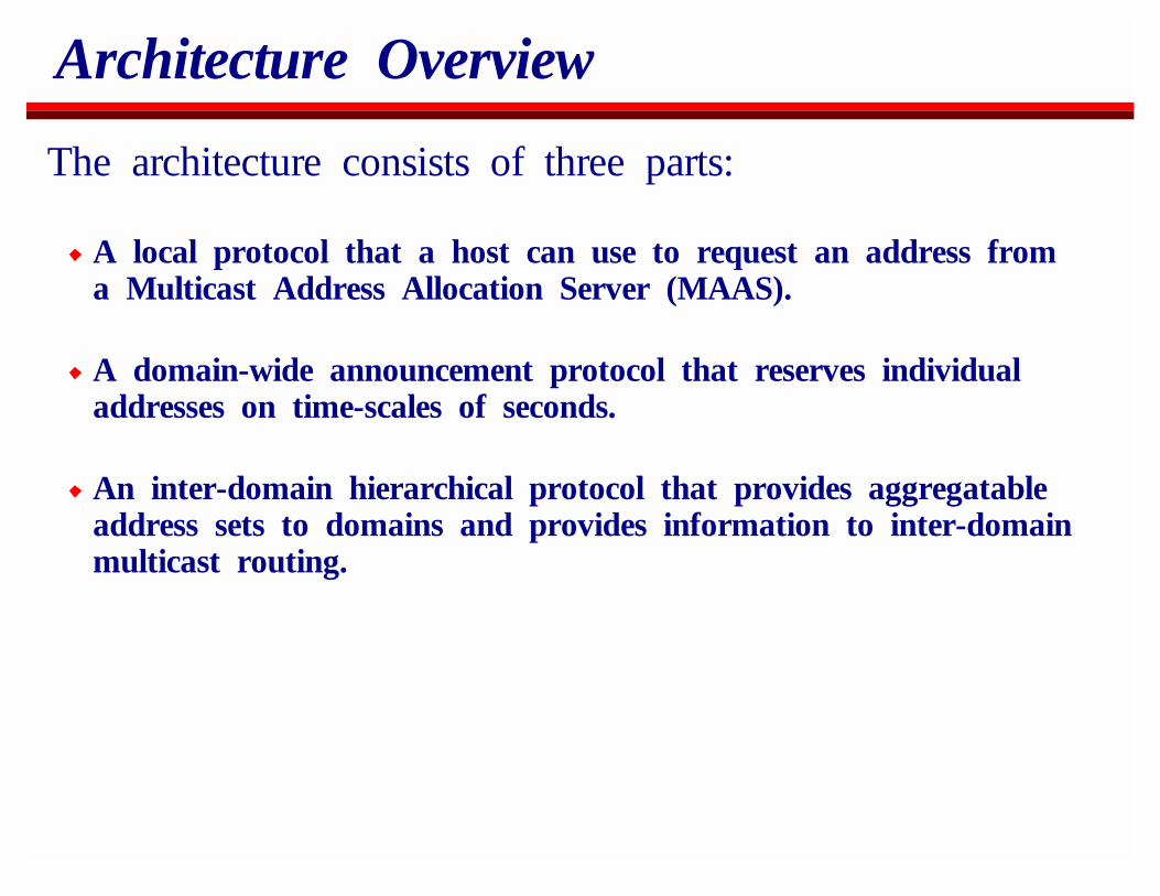
The architecture consists of three parts:
A local protocol that a host can use to request an address froma Multicast Address Allocation Server (MAAS).
A domain-wide announcement protocol that reserves individualaddresses on time-scales of seconds.
An inter-domain hierarchical protocol that provides aggregatableaddress sets to domains and provides information to inter-domainmulticast routing.
Requesting an Address from a MAAS
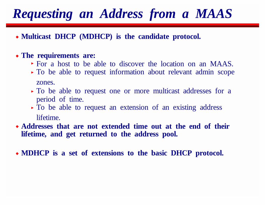
Multicast DHCP (MDHCP) is the candidate protocol.
The requirements are:For a host to be able to discover the location on an MAAS.To be able to request information about relevant admin scopezones.To be able to request one or more multicast addresses for aperiod of time.To be able to request an extension of an existing addresslifetime.
Addresses that are not extended time out at the end of theirlifetime, and get returned to the address pool.
MDHCP is a set of extensions to the basic DHCP protocol.
Domain Wide Address Allocation
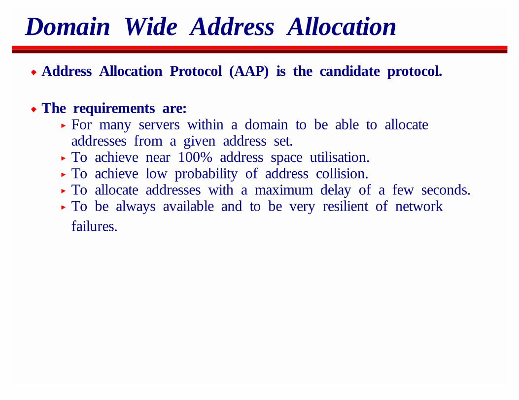
Address Allocation Protocol (AAP) is the candidate protocol.
The requirements are:For many servers within a domain to be able to allocateaddresses from a given address set.To achieve near 100% address space utilisation.To achieve low probability of address collision.To allocate addresses with a maximum delay of a few seconds.To be always available and to be very resilient of networkfailures.
Inter-domain Address Set Allocation
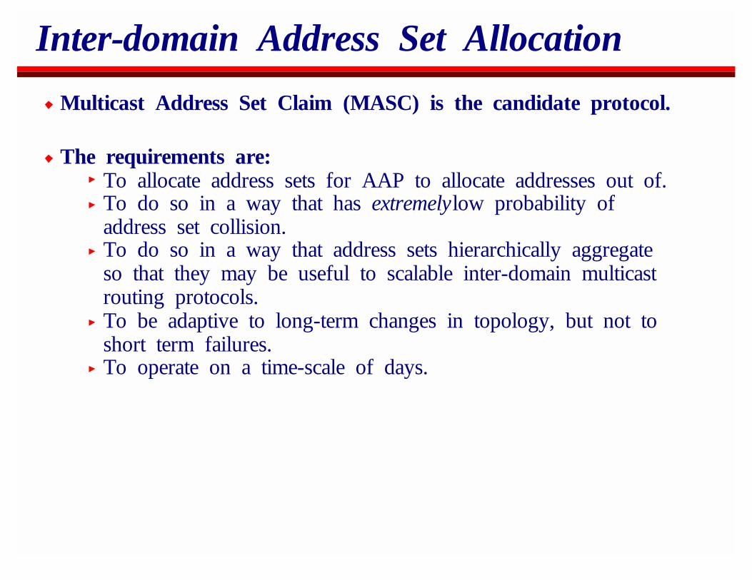
Multicast Address Set Claim (MASC) is the candidate protocol.
The requirements are:To allocate address sets for AAP to allocate addresses out of.To do so in a way that has extremelylow probability ofaddress set collision.To do so in a way that address sets hierarchically aggregateso that they may be useful to scalable inter-domain multicastrouting protocols.To be adaptive to long-term changes in topology, but not toshort term failures.To operate on a time-scale of days.
Note on MASC and multicast routing
It’s easy to get confused about the relationship between MASC,BGP and BGMP
They run in the same routers but are conceptually separate.MASC uses information from unicast routing to allocateaddress sets.BGP4+ (MBGP) will then distribute these address sets in aG-RIB.BGMP uses the G-RIB to do multicast routing.
MASC is not tied to BGP or BGMP, but we expect it to be usedthis way in practice.
Allocation Domains
An allocation domain will typically be an AS.AAP allocates addresses within each domain.MASC allocates address sets to each domain.
If a unicast AS is too large, it can be split into multiple multicastAS’s and BGMP run at the internal border.
If a single AS is allocating too few addresses and is singlyconnected, it should not be its own domain, but should be partof its parent domain instead.
This can be configured to happen adaptively.
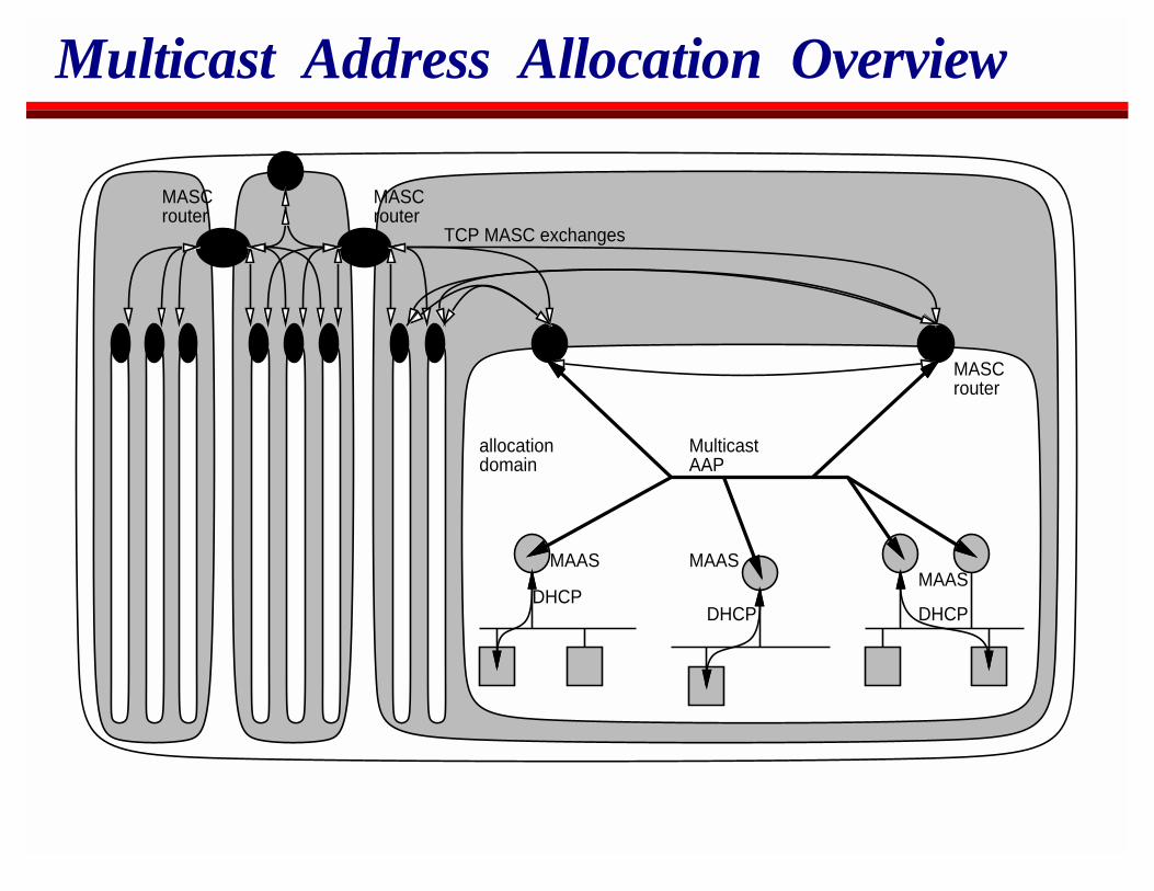
Multicast Address Allocation Overview
allocationdomain
MulticastAAP
DHCPDHCPDHCP
MAAS MAASMAAS
MASCrouter
TCP MASC exchanges
MASCrouter
MASCrouter

Multicast Address Allocation Example
Client
MDHCP scoperequest
MDHCP scope response
MDHCP addressrequest
MDHCP addressallocation
local MAASserver
remote MAASserver
MASCnode for domain
AAP AddressSet Advertisement
AAP address claim
AAP address collide (a rare event)
AAP address claimafter AAP timeout(eg 3 seconds)
AAP address set usage report
Periodic AAPaddress claim
after MASC claiminterval (eg 2 days)
AAP address setadvertisement
AAPMDHCP
OverviewIP MulticastReal-Time Traffic on the InternetSecuritySession AnnouncementsSession InvitationH.323Multicast Address AllocationStream Control: RTSPBetter ServiceCodecs and Media PacketizationCongestion Control for Multimedia
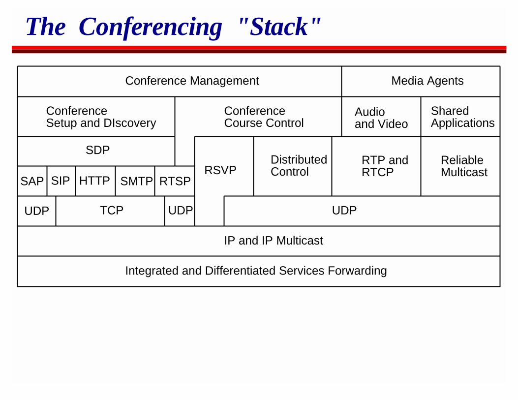
The Conferencing "Stack"
IP and IP Multicast
Integrated and Differentiated Services Forwarding
UDP TCP
SAP SIP HTTP SMTP
SDP
ConferenceSetup and DIscovery
ConferenceCourse Control
RSVPDistributedControl
RTP andRTCP
ReliableMulticast
Audioand Video
SharedApplications
Conference Management Media Agents
UDPUDP
RTSP
Real-Time Stream (Control) Protocol(RTSP)
RTSP provides a way to set up and control multimedia streamsfrom a media server.
Essentially RTSP is the remote control for a network-VCR.
RTSP is in the same "protocol family" as SIP and HTTP:text basedMIME-format messagesHTTP-like syntaxshared response codes.
RTSP functionality
Setup a connection and exchange stream transport informationDescribe the sessionPlay the session
from specified start timesforwards, backwardsat different speeds and data rates
Record a sessionPause playback or recording
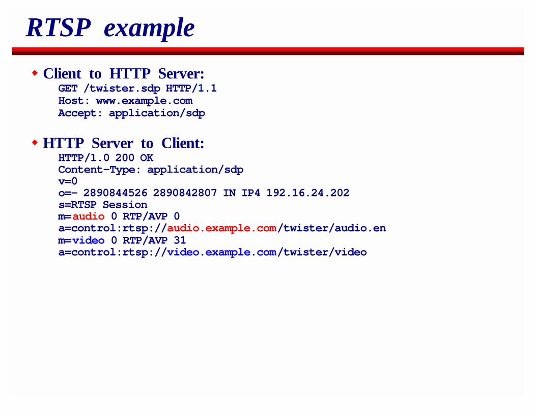
RTSP example
Client to HTTP Server:GET /twister.sdp HTTP/1.1Host: www.example.comAccept: application/sdp
HTTP Server to Client:HTTP/1.0 200 OKContent-Type: application/sdpv=0o=- 2890844526 2890842807 IN IP4 192.16.24.202s=RTSP Sessionm=audio 0 RTP/AVP 0a=control:rtsp://audio.example.com/twister/audio.enm=video 0 RTP/AVP 31a=control:rtsp://video.example.com/twister/video
RTSP example
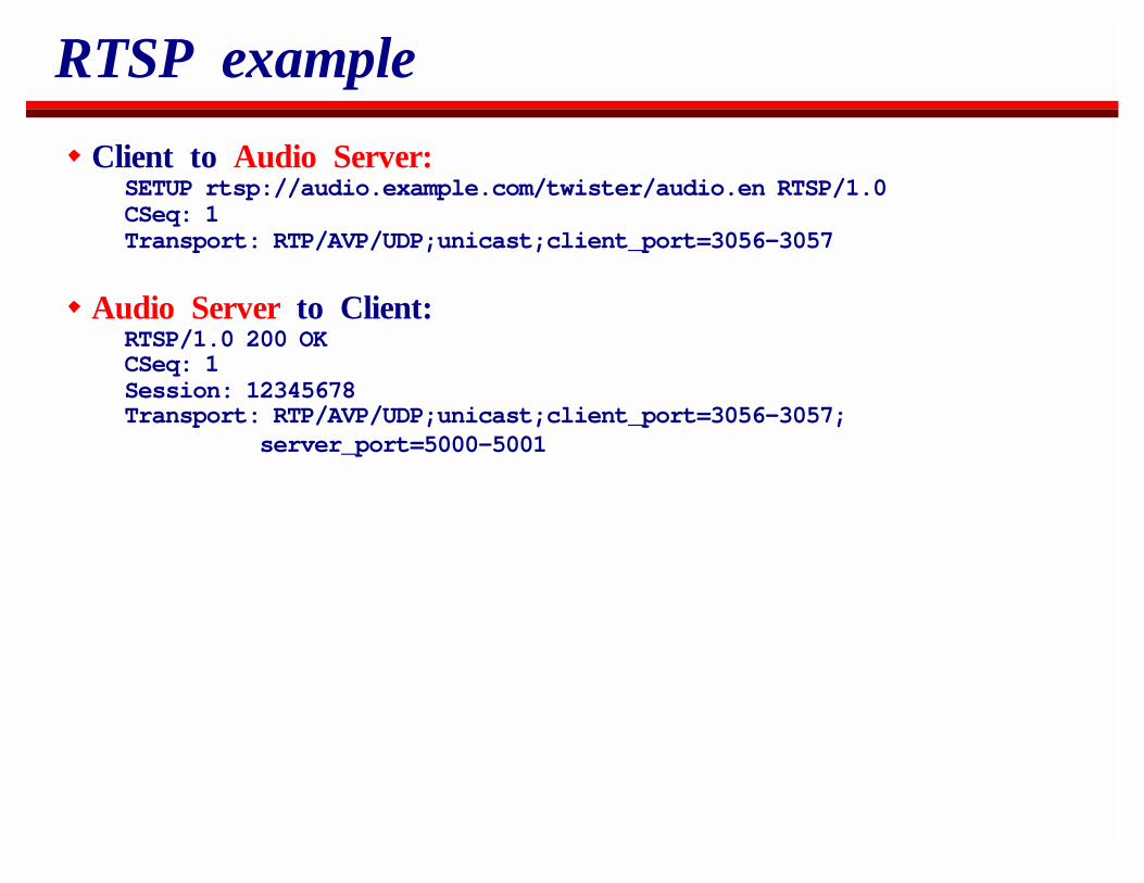
Client to Audio Server:SETUP rtsp://audio.example.com/twister/audio.en RTSP/1.0CSeq: 1Transport: RTP/AVP/UDP;unicast;client_port=3056-3057
Audio Server to Client:RTSP/1.0 200 OKCSeq: 1Session: 12345678Transport: RTP/AVP/UDP;unicast;client_port=3056-3057;
server_port=5000-5001
RTSP example
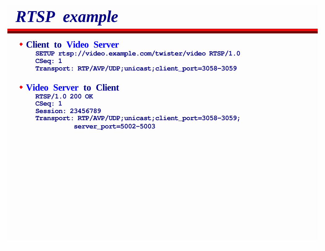
Client to Video ServerSETUP rtsp://video.example.com/twister/video RTSP/1.0CSeq: 1Transport: RTP/AVP/UDP;unicast;client_port=3058-3059
Video Server to ClientRTSP/1.0 200 OKCSeq: 1Session: 23456789Transport: RTP/AVP/UDP;unicast;client_port=3058-3059;
server_port=5002-5003
RTSP example
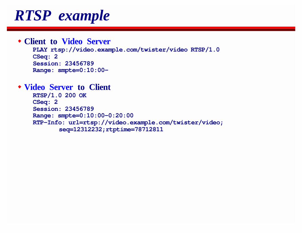
Client to Video ServerPLAY rtsp://video.example.com/twister/video RTSP/1.0CSeq: 2Session: 23456789Range: smpte=0:10:00-
Video Server to ClientRTSP/1.0 200 OKCSeq: 2Session: 23456789Range: smpte=0:10:00-0:20:00RTP-Info: url=rtsp://video.example.com/twister/video;
seq=12312232;rtptime=78712811
RTSP example
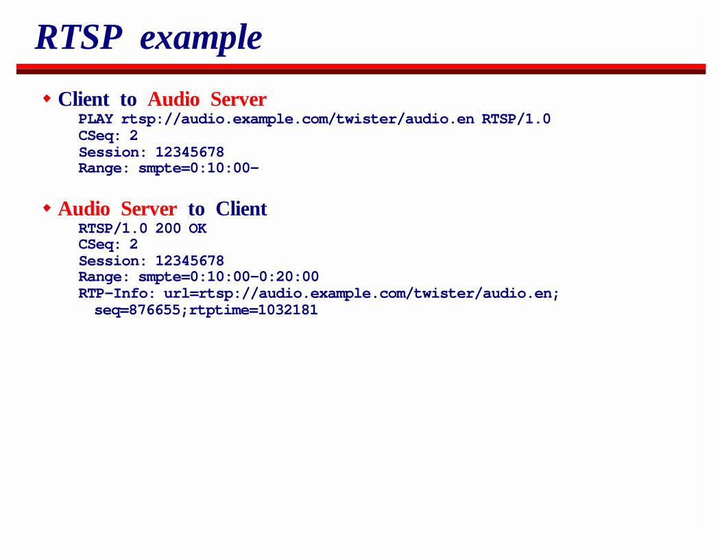
Client to Audio ServerPLAY rtsp://audio.example.com/twister/audio.en RTSP/1.0CSeq: 2Session: 12345678Range: smpte=0:10:00-
Audio Server to ClientRTSP/1.0 200 OKCSeq: 2Session: 12345678Range: smpte=0:10:00-0:20:00RTP-Info: url=rtsp://audio.example.com/twister/audio.en;seq=876655;rtptime=1032181
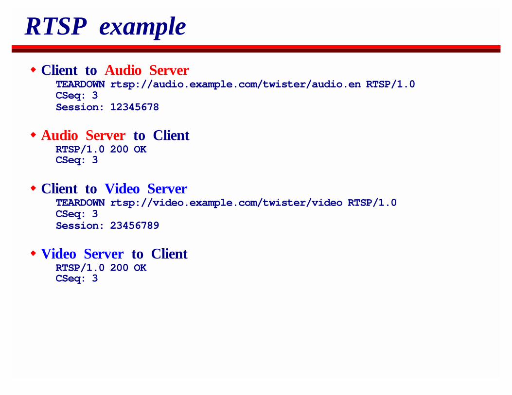
RTSP example
Client to Audio ServerTEARDOWN rtsp://audio.example.com/twister/audio.en RTSP/1.0CSeq: 3Session: 12345678
Audio Server to ClientRTSP/1.0 200 OKCSeq: 3
Client to Video ServerTEARDOWN rtsp://video.example.com/twister/video RTSP/1.0CSeq: 3Session: 23456789
Video Server to ClientRTSP/1.0 200 OKCSeq: 3
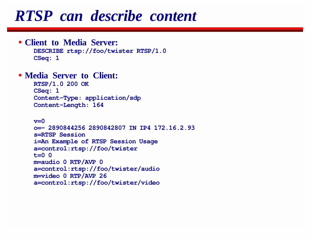
RTSP can describe content
Client to Media Server:DESCRIBE rtsp://foo/twister RTSP/1.0CSeq: 1
Media Server to Client:RTSP/1.0 200 OKCSeq: 1Content-Type: application/sdpContent-Length: 164
v=0o=- 2890844256 2890842807 IN IP4 172.16.2.93s=RTSP Sessioni=An Example of RTSP Session Usagea=control:rtsp://foo/twistert=0 0m=audio 0 RTP/AVP 0a=control:rtsp://foo/twister/audiom=video 0 RTP/AVP 26a=control:rtsp://foo/twister/video
Live Media Presentation
RTSP can use multicast to distribute live media.
In this case the server specifies the multicast address and portin the SDP returned by the DESCRIBE response.
SETUP and PLAY are a little superfluous except for the firstreceiver to join the group, but the client must issue themanyway.
Streaming into Conferences
RTSP can stream media into a pre-existing multicast conference.
The server possesses the description of the recording includingthe protocol and formats available.
The client knows the destination addresses and ports and theprotocol and formats allowed in the conference.
So long as the media protocols and formats are compatible,the client can specify the destination addresses and ports forthe server to stream to.
Recording Multicast Conferences
Not all RTSP servers support recording, but the protocol allows it.
First the client needs to inform the server of all the details of theconference.
It does this by sending an ANNOUNCE request containing thecomplete SDP description of the session to be recorded.
SETUP is still required, although this repeats information in thesession description.
The client then issues a RECORD request, which can specify timeranges to be recorded.
RTSP: Summary
RTSP can:Playback unicast streams from one or many servers
Forward, Backward, Skip, Pause, Fast, Slow, etcInitiate live multicast streamsPlayback recorded multimedia into a multicast conferenceRecord unicast or multicast conferences
It’s also sufficiently similar to HTTP and SIP that a single server caneasily handle all three if desired.
OverviewIP MulticastReal-Time Traffic on the InternetSecuritySession AnnouncementsSession InvitationH.323Multicast Address AllocationStream ControlBetter ServiceCodecs and Media PacketizationCongestion Control for Multimedia
Better ServiceRSVP/IntservDiffservwhere’s it going???
Isn’t Best Effort Service Sufficient?
In theory, yes.If there’s sufficient capacity to accommodate all the real-timeflows (as there is in the phone network) then best effort issufficient.
Queues do not buildNo packet loss occurs
If there’s not sufficient capacity to accommodate them, calls willeither block if we have reservations or give degraded service if wedon’t.
Neither of these is acceptable.Thus there must be sufficient capacity.
Isn’t Best Effort Service Sufficient?
In practice, probably not.When demand grows exponentially, ISPs trail the demand curveat least some of the time.
TCP traffic expands to fill available bandwidth and producesloss in doing so.Simple prioritization of real-time traffic leads to falselydescribed traffic.Getting from here to there is difficult - someone has to payfor the infrastructure.
The Goal
The trick is to deploy mechanisms that are:not required to obtain service, but which can be used toobtain better service if best-effort isn’t working,require minimal network state so we can build fast routers,can be charged for to improve the network for everyone,require billing arrangements that are feasible.
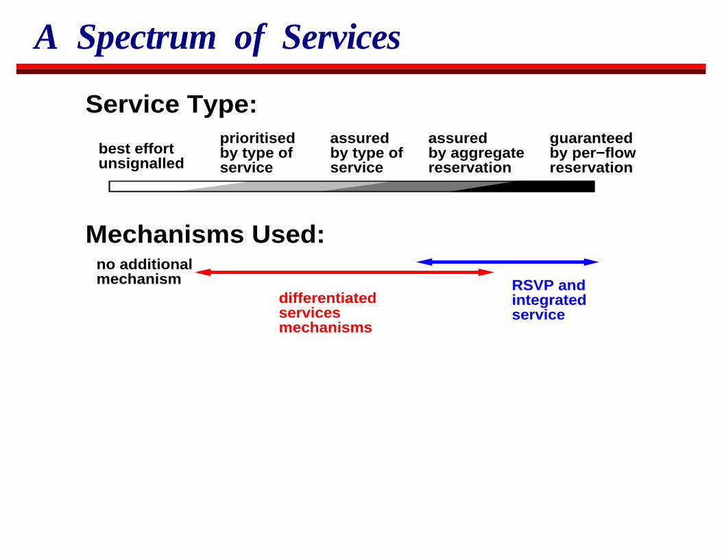
A Spectrum of Services
best effortunsignalled
guaranteedby per−flowreservation
assuredby aggregatereservation
assured by type ofservice
prioritisedby type ofservice
RSVP andintegrated service
differentiatedservicesmechanisms
Service Type:
Mechanisms Used:no additionalmechanism
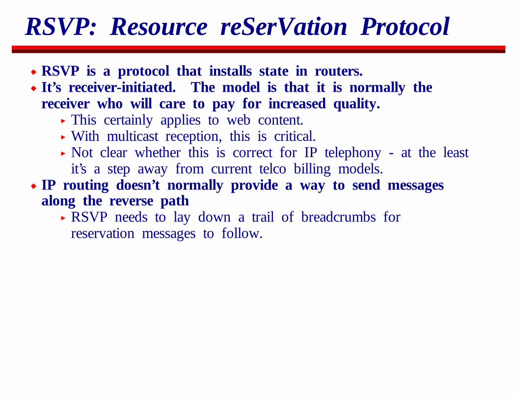
RSVP: Resource reSerVation Protocol
RSVP is a protocol that installs state in routers.It’s receiver-initiated. The model is that it is normally thereceiver who will care to pay for increased quality.
This certainly applies to web content.With multicast reception, this is critical.Not clear whether this is correct for IP telephony - at the leastit’s a step away from current telco billing models.
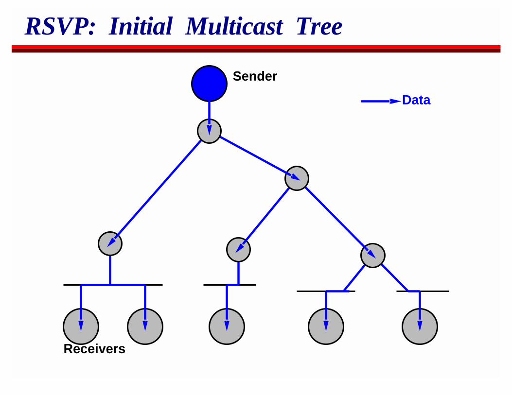
IP routing doesn’t normally provide a way to send messagesalong the reverse path
RSVP needs to lay down a trail of breadcrumbs forreservation messages to follow.
RSVP: Initial Multicast Tree
Sender
Receivers
Data
RSVP: Path Messages
Sender
Receivers
Data
RSVPpathMessages
PathState
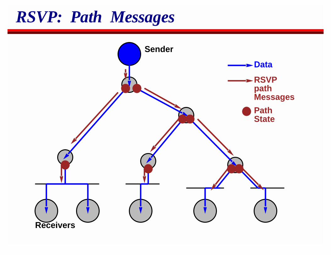
RSVP: Reservation Request
Sender
Receivers
Data
RSVPpathMessages
RSVP reservationrequest
IntservForwardingState
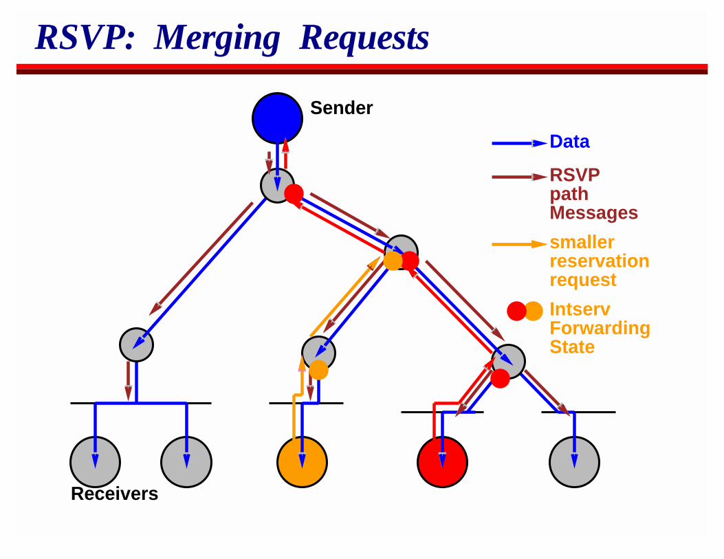
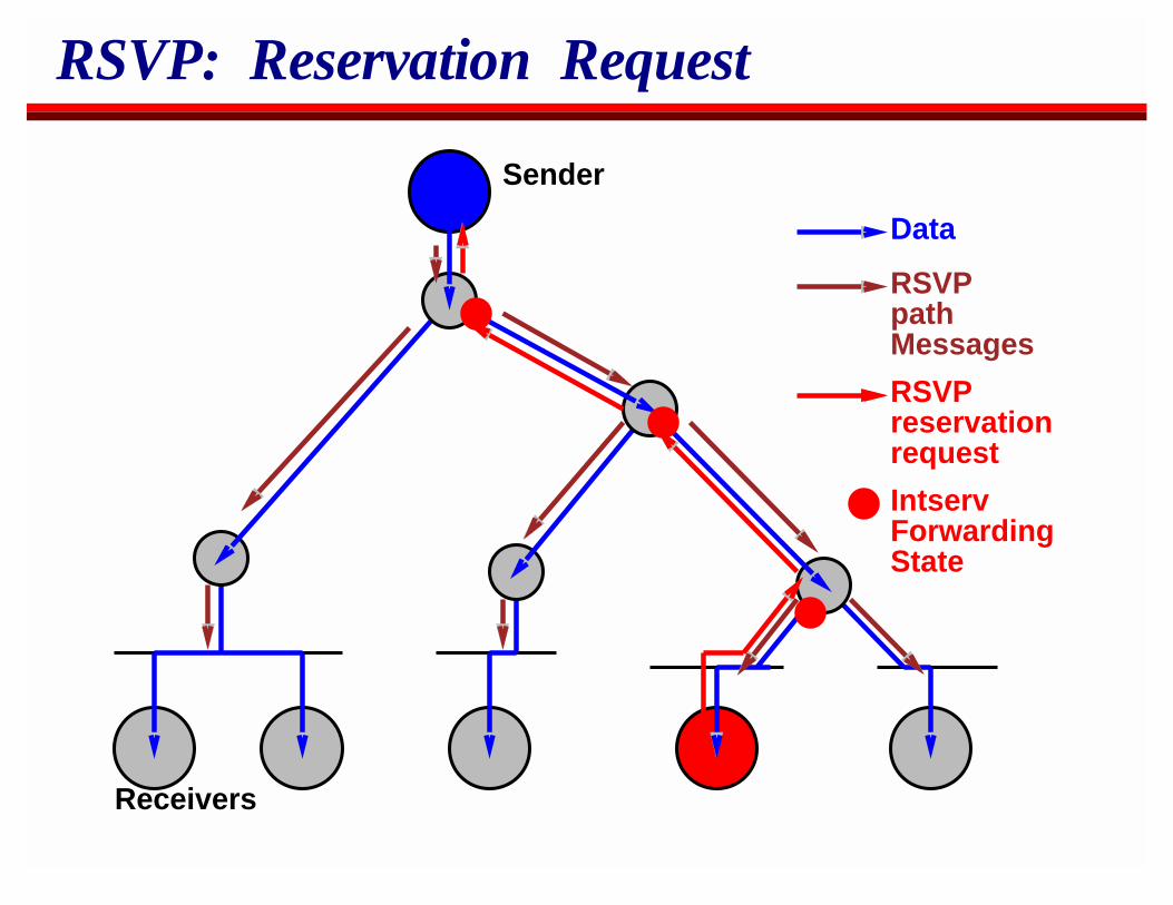
RSVP: Merging Requests
Sender
Receivers
Data
RSVPpathMessages
IntservForwardingState
smaller reservationrequest
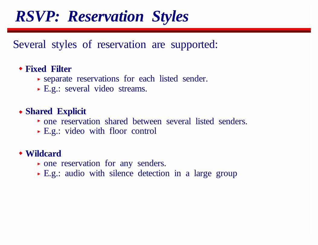
RSVP: Reservation Styles
Several styles of reservation are supported:
Fixed Filterseparate reservations for each listed sender.E.g.: several video streams.
Shared Explicitone reservation shared between several listed senders.E.g.: video with floor control
Wildcardone reservation for any senders.E.g.: audio with silence detection in a large group
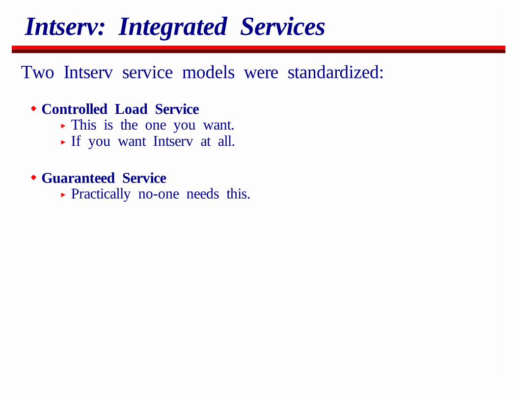
Intserv: Integrated Services
Two Intserv service models were standardized:
Controlled Load ServiceThis is the one you want.If you want Intserv at all.
Guaranteed ServicePractically no-one needs this.
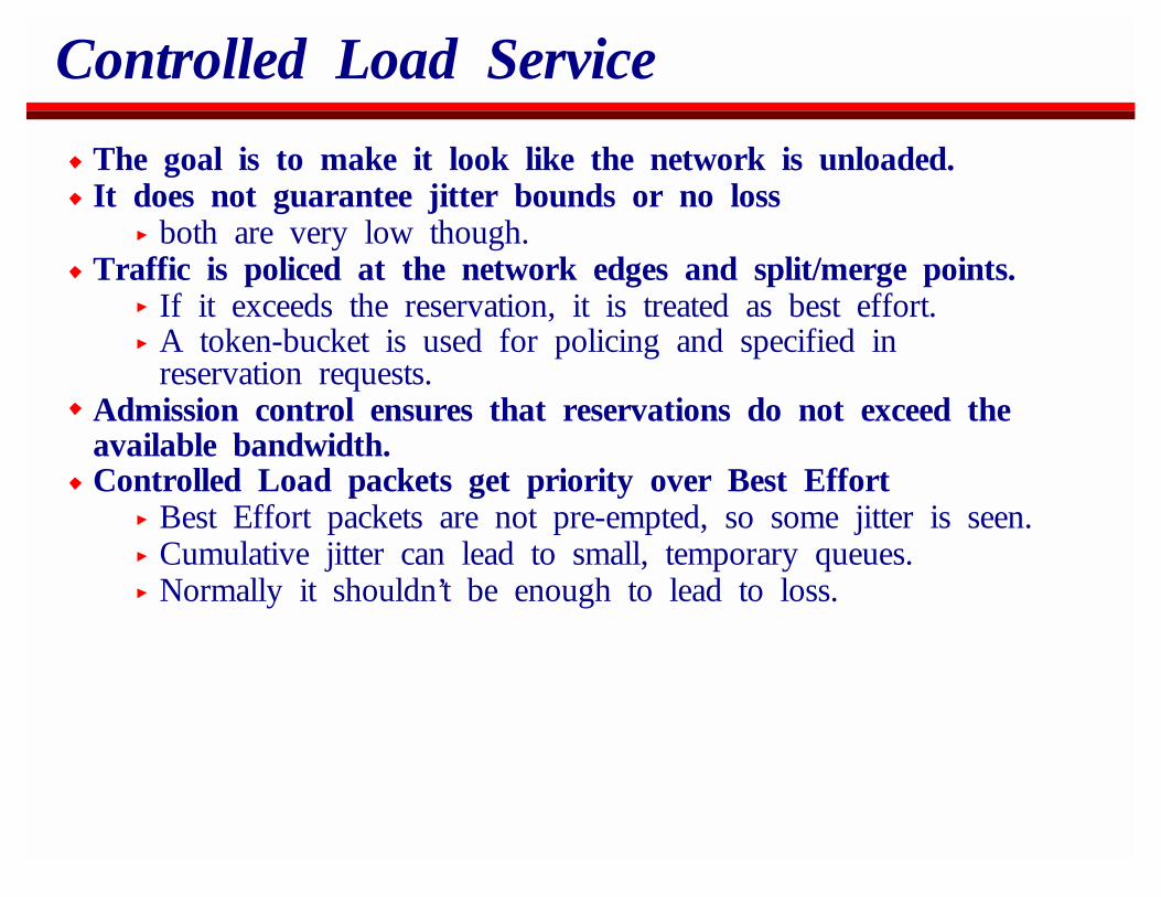
Controlled Load Service
The goal is to make it look like the network is unloaded.It does not guarantee jitter bounds or no loss
both are very low though.Traffic is policed at the network edges and split/merge points.
If it exceeds the reservation, it is treated as best effort.A token-bucket is used for policing and specified inreservation requests.
Admission control ensures that reservations do not exceed theavailable bandwidth.Controlled Load packets get priority over Best Effort
Best Effort packets are not pre-empted, so some jitter is seen.Cumulative jitter can lead to small, temporary queues.Normally it shouldn’t be enough to lead to loss.
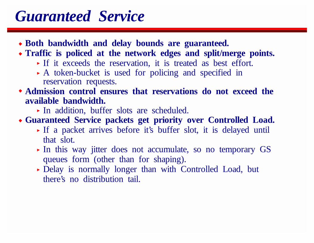
Guaranteed Service
Both bandwidth and delay bounds are guaranteed.Traffic is policed at the network edges and split/merge points.
If it exceeds the reservation, it is treated as best effort.A token-bucket is used for policing and specified inreservation requests.
Admission control ensures that reservations do not exceed theavailable bandwidth.
In addition, buffer slots are scheduled.Guaranteed Service packets get priority over Controlled Load.
If a packet arrives before it’s buffer slot, it is delayed untilthat slot.In this way jitter does not accumulate, so no temporary GSqueues form (other than for shaping).Delay is normally longer than with Controlled Load, butthere’s no distribution tail.
Why isn’t everyone doing it?
The protocols and mechanisms work fine.It solves the problem people thought they wanted solved.Two Problems:
Charging/authenticationRouter State
RSVP/Intserv Charging
A reservation goes hop-by-hop across many ISPs.Why should I reserve bandwidth for some receiver I’ve neverheard of?
Need negative feedback to discourage reservations oreverything gets reserved.Essentially this means charging.
Vanilla RSVP needs n^2 billing arrangements between n ISPs.
Router State
Backbone routers currently handle O(100,000) simultaneousconnections.We don’t want a significant proportion of these to havereservation state.
Router memory is (still) expensive.CPU Cycles to check the flow spec are in very short supply.
Bandwidth is growing faster than Moore’s LawIn the future we’ll have less cycles per packet than we havenow.
Router State: Solutions?
Aggregate ReservationsThis is an active research area.
Only police/install state at the edges.Do something different (or nothing at all) in the backbone.
Differentiated Services
There are two ways to get different service for your packets:
Install filter state in routers.Use the filter to recognize compliant packets.Give them different service.
Set bits in the packets.Use the bits to recognize compliant packets.Give them different service.
Intserv does the former, Diffserv does the latter.
Services vs Hop-by-hop behaviours.
There are not many bits in an packet we can use.8 TOS bits, but 2 provisionally allocated to ECN
If this is to go fast, the bits must specify the behaviour that therouter should apply to the packet.
Thus there are not many behaviours we can specify.Actually there aren’t that many we want to specify either.
Services vs Hop-by-hop behaviours.
An end-to-end service is comprised of three parts:Admission controlPolicers that set or clear TOS bits.Routers that use these TOS bits to give different service.
A small number of TOS bits/per-hop behaviours can provide alarge number of end-to-end services depending on the admissioncontrol and policing.
The hard part will be ensuring that these services can co-exist.If this is to be determinable, the per-hop behaviours need tobe rigorously defined.
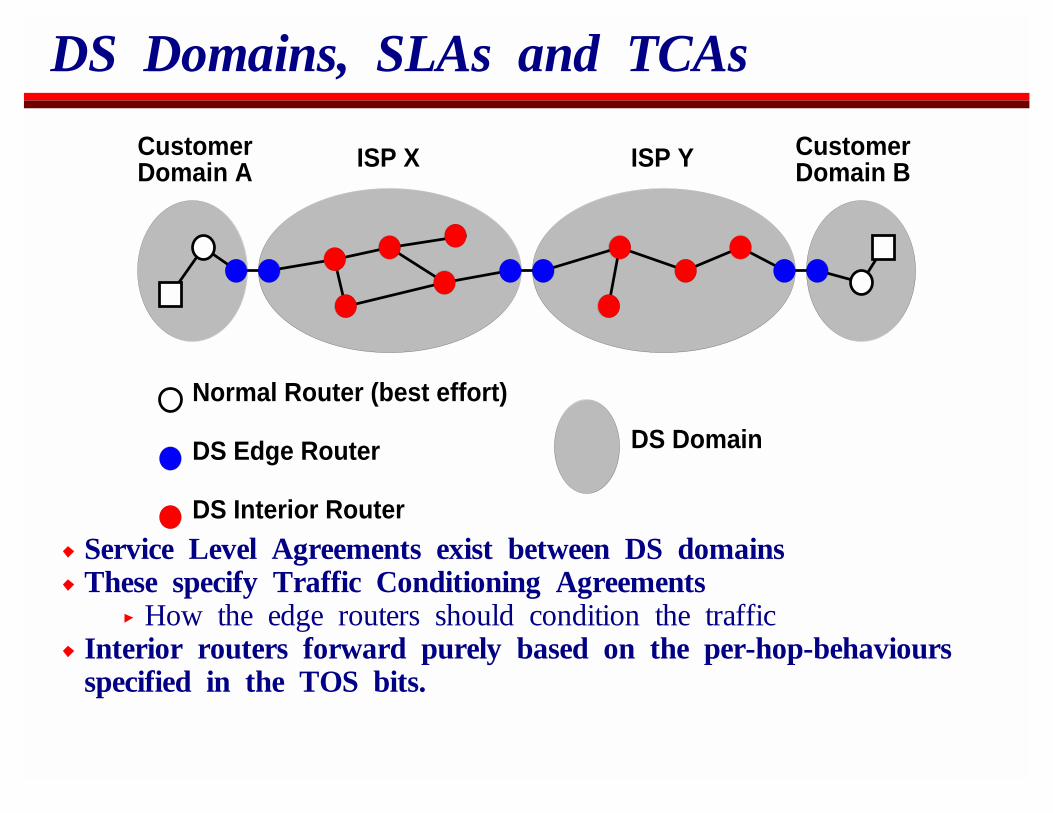
DS Domains, SLAs and TCAs
CustomerDomain A ISP X ISP Y Customer
Domain B
DS Interior Router
DS Edge Router
Normal Router (best effort)
DS Domain
Service Level Agreements exist between DS domainsThese specify Traffic Conditioning Agreements
How the edge routers should condition the trafficInterior routers forward purely based on the per-hop-behavioursspecified in the TOS bits.
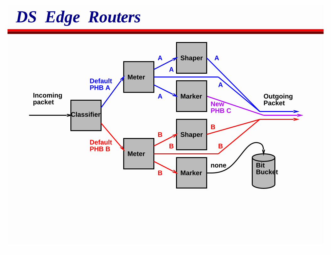
DS Edge Routers
Incomingpacket
Classifier
DefaultPHB A
DefaultPHB B
Meter
Shaper
Marker
Shaper
Marker
Meter
BitBucket
A
A
A
B
B
B
A
A
NewPHB C
B
B
none
OutgoingPacket
Diffserv Services
As far as I can tell, no two people have the same idea aboutwhat Diffserv End to End services will be.Possible services:
Dave Clark’s RIOVan Jacobson’s Virtual Links
This is OK because ISPs can compete with differing businessmodels so long as the router per-hop-behaviours and SLAsbetween providers allow it.
RIO: RED with In and Out
A customer buys a connection from an ISP and also buys aenhanced service profile.
Some of their traffic is sent best-effort.Some is marked for enhanced service.
Enhanced service is independent of destination.Providers attempt to avoid over-selling enhanced service andprovision their network so it has sufficient capacity for theenhanced service traffic patterns they measure.Between providers there are bi-party arrangements for aggregatesof enhanced service traffic.
Providers buy sufficient enhanced service from their upstreamprovider to satisfy their measured normal requirements.Higher spot prices might be charged.Policing is only done on the aggregate at provider boundaries.
Virtual Links
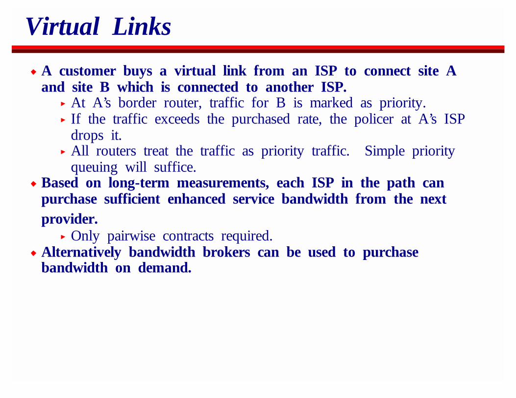
A customer buys a virtual link from an ISP to connect site Aand site B which is connected to another ISP.
At A’s border router, traffic for B is marked as priority.If the traffic exceeds the purchased rate, the policer at A’s ISPdrops it.All routers treat the traffic as priority traffic. Simple priorityqueuing will suffice.
Based on long-term measurements, each ISP in the path canpurchase sufficient enhanced service bandwidth from the nextprovider.
Only pairwise contracts required.Alternatively bandwidth brokers can be used to purchasebandwidth on demand.
Diffserv status
Diffserv emerged from Van Jacobson and Dave Clark’s proposals.Others are now driving the show.Per hop behaviours are currently being standardized.Admission control, policers, bandwidth brokers and actual servicedefinitions are still being worked out.
There’s still a need for a mechanism by which an application canrequest enhanced service from its local Diffserv gateway
RSVP looks like being used in this role.
My opinion
Diffserv will see widespread deployment in the backbone.Intserv never will.Intserv will be deployed in speciality situations, and possibly inlow bandwidth edge situations.RSVP will be used to signal enhanced service.
Either it will trigger Diffserv mechanisms the whole way, or itwill trigger Intserv mechanisms at the edge and Diffservmechanisms in the network core.Diffserv-all-the-way is more likely because it’s simpler.
Best effort will still be widely used, even for multimedia dataCheaper.Still need enough bandwidth for all the customers - often itwill work well.
OverviewIP MulticastReal-Time Traffic on the InternetSecuritySession AnnouncementsSession InvitationH.323Multicast Address AllocationStream ControlBetter ServiceCodecs and Media PacketizationCongestion Control for Multimedia
Codecs and Media PacketizationCoding for LossReceiver RepairPacket-level FEC
Coding for Packet Loss
Traditional coding theory states that you should compress yourdata as much as possible independent on the channel, and thenadd sufficient redundancy to ensure all your data gets through.
Traditional coding theory never had to deal with realtime dataon the Internet.Bit errors aren’t the problem - packet loss is.Packet-level FEC works well only when delay can be added.
Generic Compression Scheme
Difference QuantizeHuffmanCode
HuffmanDecode Dequantize Add
PredictorPrediction Predictor
Prediction
OriginalSignal
TransmitCompressedSignal
DecompressedSignal
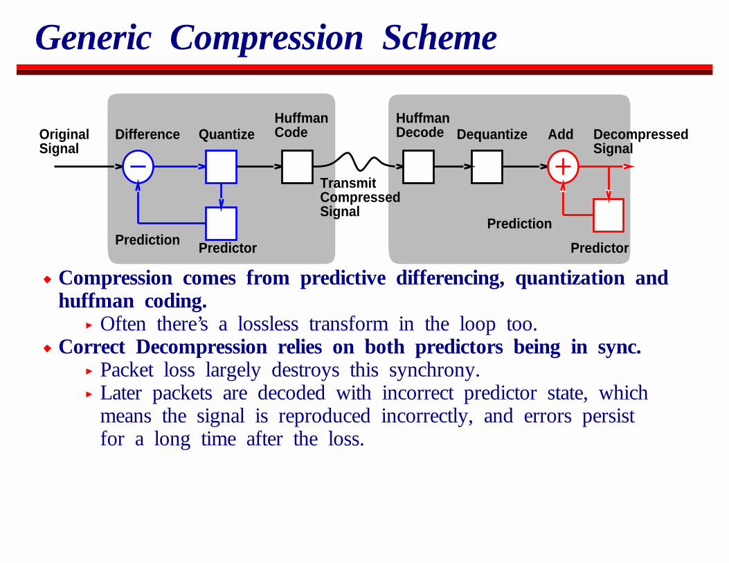
Compression comes from predictive differencing, quantization andhuffman coding.
Often there’s a lossless transform in the loop too.Correct Decompression relies on both predictors being in sync.
Packet loss largely destroys this synchrony.Later packets are decoded with incorrect predictor state, whichmeans the signal is reproduced incorrectly, and errors persistfor a long time after the loss.
Coding for Packet Loss
Simple solution:Include the predictor state in each packet.Works fine for DVI (ADM) where the state is 1 byte.Works less well for LPC based schemes where the state islarger than the data.Works terribly for video where the state is the previous image.
General Guideline:Some decoder state is more critical than other state. Somestate can be sent with course quantization.Figure out a rough bandwidth budget and decide which stateis most important to fit in that budget.
Coding for Packet Loss
Include feedback:RTCP provides loss feedback.Use this feedback to tradeoff the bits between decoder stateand compression quality.As the loss increases, increase the compression and use thespare bits to carry more predictor state.
In general received quality is dependent on the level ofcompression and on the predictor error.
The more loss, the more important predictor error become.
Coding for Packet Loss
Change encoding modes if necessary.For example, H.261 video can comprise:
Intra-coded blocks.Inter-coded blocks.Inter-coded blocks with motion vectors.
With even small loss rates, the predictor error with motionvectors becomes terrible, and the errors move around and so donot get repaired by later intra-coded blocks.
Switch off motion vectors.With loss of (say) 5%, inter-coding introduces a lot of predictorerror.
Increase the rate of sending intra-blocks.With loss of (say) 20% inter-coding should be disabled.
Receiver Repair
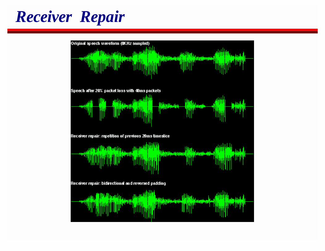
Many packet audio systems insert silence when a packet is lost.This is about the worst thing you can do.Silence demarks phonemes so is significant to the human ear.Even inserting noise is better!
Phonemes are 20-120ms long.With 40ms packets, often only part of a phoneme is lost.The surrounding packets contain information similar to thatmissing.A decent speech model can figure out when the surroundingspeech is likely to be significantly similar and use it as thebasis for speech repair.
Receiver Repair
OverviewIP MulticastReal-Time Traffic on the InternetSecuritySession AnnouncementsSession InvitationH.323Multicast Address AllocationStream ControlBetter ServiceCodecs and Media PacketizationCongestion Control for Multimedia
Congestion Control for MultimediaPlayback from ServersLive StreamsMulticast Congestion Control

Congestion Control is Hard
It’s still an active research topic after 15 years.Co-existence with TCP is important unless we’re using Diffservor Intserv.
Congestion control between streams might be important even then.
Co-existence with TCP
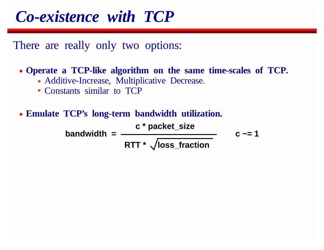
There are really only two options:
Operate a TCP-like algorithm on the same time-scales of TCP.Additive-Increase, Multiplicative Decrease.Constants similar to TCP
Emulate TCP’s long-term bandwidth utilization.
bandwidth = c * packet_size
RTT * loss_fractionc ~= 1
TCP-like algorithms
Either window or rate-based versions are possible, with or withoutretransmission.The problem is that the bandwidth signal obtained varies toogreatly for most encoders.
This is not a problem for playback where receiver bufferingcan be used to smooth the bandwidth signal from thecongestion control scheme.Live media has problems though, because there’s insufficientdelay budget to do sufficient smoothing.Multicast is hard because TCP-like algorithms require aconstant ACK stream and we can’t do this with large groups.
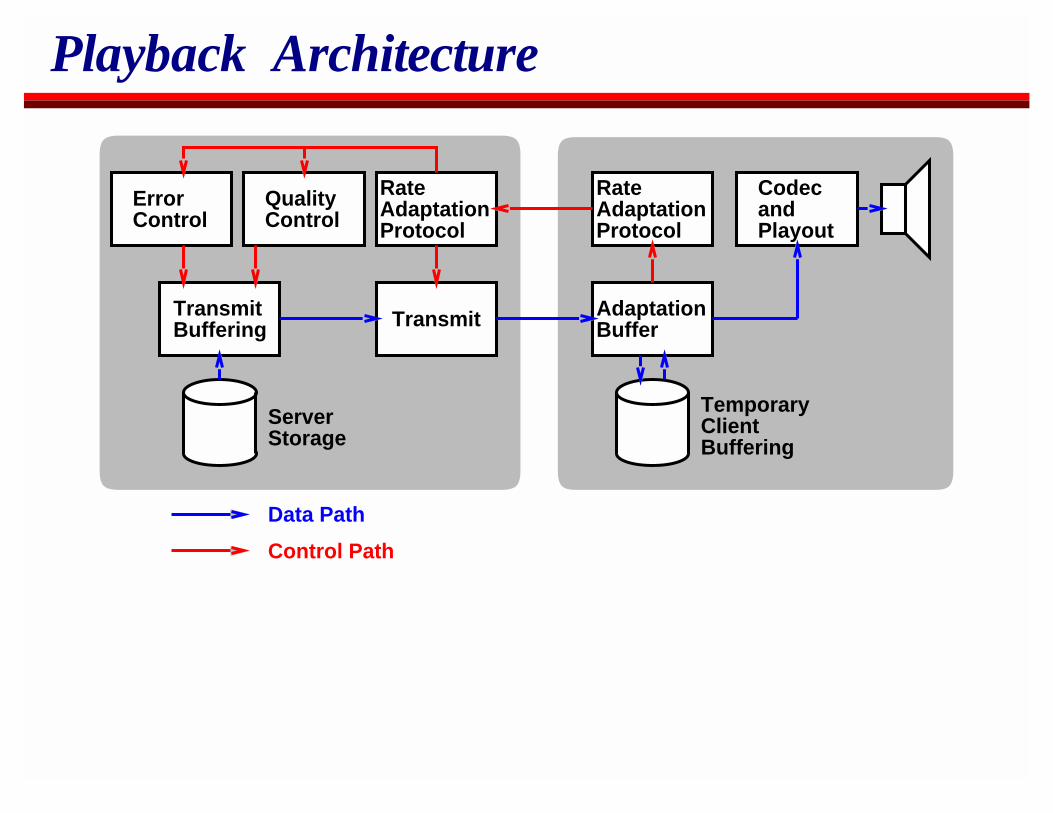
Playback Architecture
ErrorControl
QualityControl
RateAdaptationProtocol
Transmit AdaptationBuffer
TransmitBuffering
RateAdaptationProtocol
CodecandPlayout
Data Path
Control Path
ServerStorage
TemporaryClientBuffering
Playback Architecture
The Rate Adaptation Protocol determines the bandwidth.This is never exceeded.Any retransmissions also come from this bandwidth budget.The signal is very noisy.
When more bandwidth is available, higher quality data can besent.
But FIRST, we send faster than the consumption rate to buildup some buffering at the receiver so that we can cope withunexpected future variations in measured bandwidth.Only when we believe there’s sufficient receiver buffering tocope with likely future backoffs do we increase the bandwidth.
Quality Adjustment
There are three options for changing quality:Server recodes the stream on the fly (transcoding)
Typically this is too expensive on a busy server.Server switches between multiple copies stored with differentqualities.
Need "crossover points" where predictor state will be the same.Server stores data as a layered encoding and adds or dropslayers to change bandwidth.
Seems promising, but the codecs aren’t widely used currently.We’re actively researching this approach.