mark ahu · 4. 1.2 type indication. type dimensions (mm) ahu 15-15 975x975 ahu 15-20 975x1280 ahu...
TRANSCRIPT
Technical manual ENM
AR
K A
HU
06 6
1 00
0_R
05

2
EN
3
Read this document before installing the appliance
WarningIncorrect installation, adjustment, alteration, repair or maintenance activity may lead to material damage or injury. All work must be carried out by approved, qualified professionals. If the appliance is not positioned in accordance with the instructions, the warranty shall be rendered void.
If the manual refers to an image or table, a number will be shown between square brackets, for example [3]. The number refers to images and tables at the back of the manual with the stated number.
1.0 General
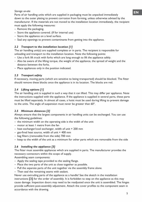
1.1 ApplicationThe Mark AHU air handling unit can be used for a variety of air handling purposes. It is able to supply various types of buildings and rooms with ventilation air, either hot or cool as required. The size of the Mark AHU depends on the number of ventilation cycles required, and the heating and/or cooling capacity. The Mark AHU is available in various dimensions and air quantities from 5000m3/h to 69500m3/h. The air handling unit can be supplied in a number of assemblies on request. From a simple ventilation unit suitable for air intake and exhaust to a mixing box, filtering, heating, cooling, humidifying, heat recovery and sound attenuation unit. If heating areas in which there are corrosive vapours (chlorinated hydrocarbons in particular) which are either produced directly in the area, or may be drawn in from the outside by the air handling unit via a connection or an open connector, indirect gas heaters cannot be used because of the risk of corrosion. Consult the manufacturer for use in, or close to, swimming pools.The unit is suitable for the operating parameters indicated on the type plate.– Median temperature (air, water, coolant and air humidity)– The unit must not be used in explosive area unless otherwise indicated.– The maximum current consumption must not be exceeded.You may deviate from the agreements above only with the manufacturer’s agreement in writing.
Subject to changeThe manufacturer is committed to constantly improving its products and reserves the right to make changes in the specifications without prior notice. The technical details are considered correct but do not form the basis for a contract or warranty. All orders are accepted according to the standard terms of our general sales and delivery conditions (available upon request).
4
1.2 Type indication
Type Dimensions (mm)AHU 15-15 975x975AHU 15-20 975x1280AHU 20-20 1280x1280AHU 25-20 1530x1280AHU 30-20 1890x1280AHU 35-25 2195x1530AHU 35-35 2195x1530AHU 40-35 2508x2195 1.3 General warningsIncorrect installation, adjustment, alteration, maintenance activity or repair may lead to material or environmental damage and/or injuries. The appliance should therefore be installed, adapted or converted by a skilled and qualified installer, taking into account national and international regulations. Faulty installation, adjustment, alteration, maintenance activity or repair shall render the warranty void.
1.4 SafetyThe air treatment unit must be fitted with a lockable isolator switch (not supplied as standard). Always disconnect the appliance from the mains when carrying out maintenance or repairs. The motor and fan take some time to stop after the voltage has been switched off. Wait for at least two minutes before opening the fan doors. Always comply with national and/or regional regulations.
2.0 Positioning the appliance
On receipt, check immediately that the supply had been delivered in full. Check also for any damage caused during transportation. If what is delivered does not comply with the goods indicated on the packing list, and/or damage during transportation is recorded, the recipient must state this on the delivery note indicating the date of receipt. If the recipient fails to comply with the requirements above, he shall have no right to claim.
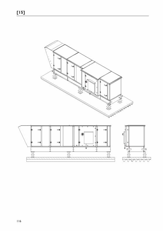
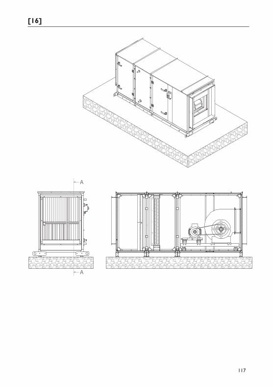
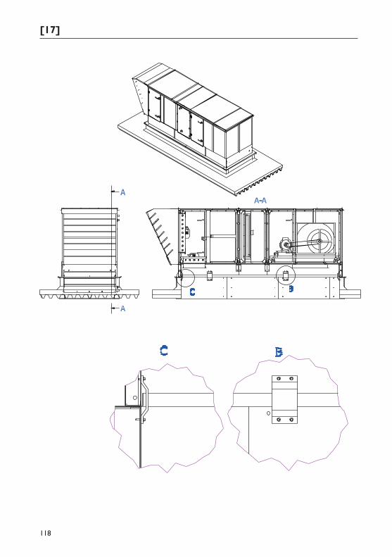
2.1 Assembly [15] [16] [17]To avoid contact noise, we recommend that the air handling unit be placed on a level, vibration-free floor or roof structure. The roof structure must be sufficiently stable, and must have enough load-bearing points to prevent the air handling unit from bending. The air handling unit must be attached to the roof structure. The unit must be placed on a level surface to ensure that any condensation is properly drained off. Air handling units incorrectly installed can cause the inspection doors in the unit to jam and possibly result in the unit leaking. With units with a condensation extractor, the height of the installation structure must be at least the same, or higher, than the required siphon height. Note: if the air treatment unit replaces the roof in the location where it is installed, the manufacturer must be aware of this in advance so that appropriate measures may be applied.
EN
5
Storage on-siteParts of air handling units which are supplied in packaging must be unpacked immediately down to the outer plating to prevent corrosion from forming, unless otherwise advised by the manufacturer. If the materials are not moved to the installation location immediately, the recipient must apply the following measures:– Remove the packaging.– Store the appliance covered. (If for internal use)– Store the appliance on a level surface.– Seal any openings to prevent contaminants from getting into the appliance.
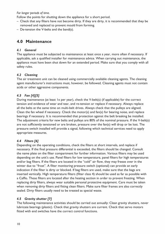
2.2 Transport to the installation location [1]The air handling unit(s) are supplied complete or in parts. The recipient is responsible for unloading and transport to the installation location. Note the following points: – Use a fork lift truck with forks which are long enough to lift the appliance safely. – Also be aware of the lifting torque, the weight of the appliance, the spread of weight and the
distance between the forks. – Place appliances only in the position indicated.
2.3 Transport safetyIf necessary, moving parts (which are sensitive to being transported) should be blocked. The fitter should remove these blocks once the appliance is in its location. The blocks are red.
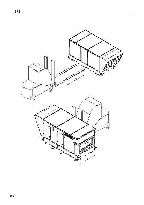
2.4 Lifting options [1]The air handling unit is supplied in such a way that it can lifted. This may differ per appliance. Note the instructions supplied with the appliance. If the appliance is supplied in several parts, these parts must be lifted separately. In almost all cases, a hoist must be used during lifting to prevent damage to the units. The angle of suspension must never be greater than 60º.
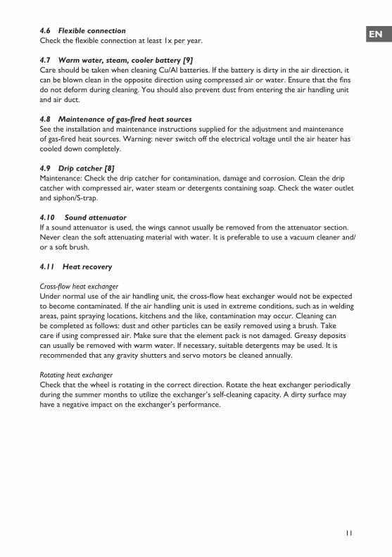
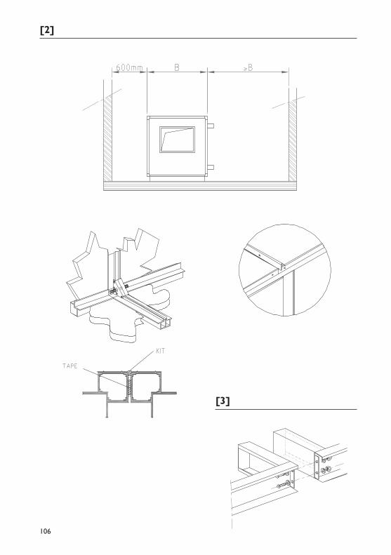
2.5 Minimum distances [2]Always ensure that the largest components in air handling units can be exchanged. You can use the following guidelines:– the minimum width on the operating side is the width of the unit:– motor at least 1 metre from the fan – heat exchanger/cool exchanger, width of unit + 200 mm– gas-fired heat source, width of unit + 400 mm– bag filters (removable from the side) 700 mm– keep to the width of the unit as a minimum for other parts which are removable from the side
2.6 Installing the appliance [3]The fitter must assemble appliances which are supplied in parts. The manufacturer provides the necessary connectors within the scope of supply. Assembling seam components: – Apply the sealing tape provided to the sealing flange. – Place the two parts of the unit as close together as possible. – Pull the separate parts of the unit together via the assembly frame alone. – Then seal the remaining seams with sealant.Never use extruding parts of the appliance as a handle! See the sketch in the installation instructions [3] for the order of assembly. It is forbidden to step on the appliance as this may cause damage. Inspection doors may need to be readjusted once the unit is assembled. The hinges provide sufficient post-assembly adjustment. Attach the cover profiles to the component seam in accordance with the drawing.
6
2.7 Electrical connectionElectrical connections must be carried out in compliance with current general regional and local regulations. Cables should not run, or be installed, in the vicinity of inspections doors, panel connections and fastener profiles. To avoid damage, the electrical connection diagram in the branching box must be followed. Earth connections already installed in the air handling unit must be removed. The air ducts from the air handling unit to the appliance must be properly earthed.
2.8 Gas connectionThe air handling units can be equipped with a gas-fired heat source The gas connection between the gas-fired heat source and the gas network must be carried out in accordance with regional and local regulations. For further details, please see the installation and operating instructions supplied for the relevant gas-fired heat source. When installing the gas connection, make sure that inspection doors, panel connections and fastener profiles are not blocked. The pipes must never be installed in the air flow of the Mark AHU.
3.0 Start-up/shutdown
3.1 GeneralAppliances must be installed and started up by skilled personnel. It is important to be familiar beforehand with the installation, operating and maintenance instructions supplied as well as the maintenance instructions for air handling units and any peripherals. Disregarding these instructions could result in danger to the personnel carrying out the work, and damage the appliance. Do not forget to instruct the user on the correct use and operation of the appliance and peripherals. The appliance is suitable for the purpose for which it was designed and safe to operate only when fully installed (building, water, air, electrics, condensation etc.).
3.2 Control activitiesCheck that all screw fittings have been sufficiently tightened.Make sure that the air handling unit cannot be loaded in excess of the design parameters. Note in particular;– The fan’s maximum speed.– The fan motor’s maximum current consumption.– The maximum temperature inside the appliance < 60 ºC.
Checks prior to starting up the appliance for the first time.– Has the appliance been cleaned internally?– Have all tools been removed from the appliance?– Has all the transport protection been removed?– Can the shock absorbers under the fan frame move freely?– Are the V-pulleys correctly aligned?– Do the V-belts have the correct tension?– Have any siphons been filled with water?– Are the siphons protected from freezing?– Have the heat exchanger(s)/gas feed pipes been bled?– Have all the air ducts been installed?– Are all the components in the duct system for the correct system pressure measurement?– Are the motors connected according to the electrical diagram, and at the correct tension?– Are the motor(s)/fan(s) rotating in the right direction?
EN
7
– Are any servo motors rotating in the right direction?– Have the end switches been adjusted to stand open at 90%?– Have parts installed by third parties been tested to check that they are operational?– Have all access doors been closed during testing of the installation? – In the case of gas-fired units, never switch off the electrical voltage until the units have cooled
down completely.
3.3 Starting up components
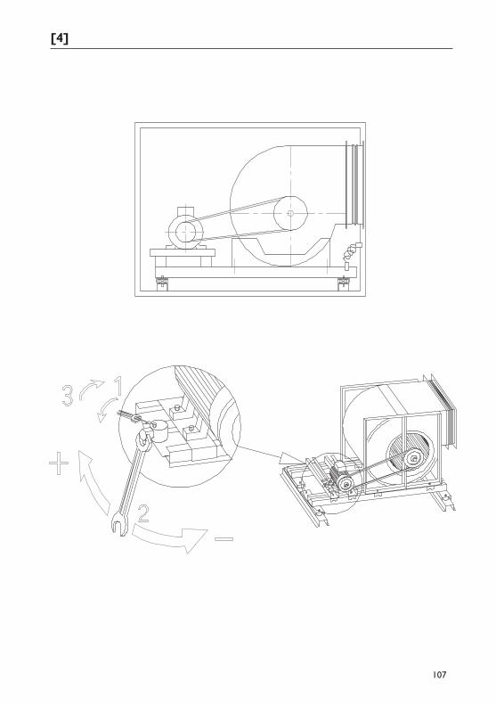
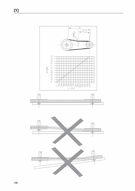
3.4 5.6 Fan [4][5]Make sure that the appliance is disconnected from the mains when working on it. Remove any (red) transport blocks. The axis of the fan(s) must always be horizontal. A load may be applied to the shock absorbers only under pressure. Check the fan motor’s direction of rotation. Remove the V-belt(s). Always check the direction of rotation when the motor is not under load. If the motor is not rotating in the required direction, the electrical wiring in the motor(s)’ branching box must be removed. Once the correct direction of rotation has been established, reinstall the V-belt(s). Check whether the pulleys are in a single line. Check that the V-belt(s) have the correct tension. The motor(s) is (are) on slide rails, which provide sufficient scope to (post-) tension the V-belt(s). Tension the slide rails as follows: – Unscrew screw 1 – Use screw 2 to set the v-belt to the correct tension. – Retighten locking screw 1.[4] Once the unit has been fully operational for 0.5 and 4 hours, the V-belt(s) must be checked to ensure they are at the right tension. Once these tasks are complete, attach any protective grills (optional). When the inspection doors are closed, the fan motor(s)’ current consumption can be measured. Current consumptions can be measured correctly only if all the installation work has been completed. The motor(s) and the fan(s) are selected on the basis of specifications provided by the customer.
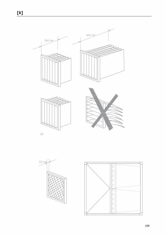
3.5 Filters [6]– Check the filter safety setting and compare it with the values on the type plate. – Check that the filters are correctly positioned (vertical).– Check that the filters are sealed from damage.
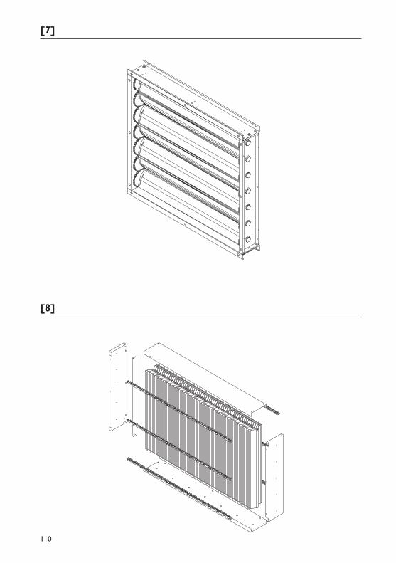
3.6 Gravity shutter [7]When installing the servo motors, make sure that no screws can hinder rotation of the fins in the valve. The servo motors fitted are permitted a maximum torque of 20 Nm.
3.7 Flexible connectionTo prevent vibrations to the (duct) system, the use of flexible connections is recommended. Make sure that the flexible connections are able to move optimally. Where flexible connections could come into contact with the external air, they must be properly thermally insulated to prevent condensation.
In the Netherlands, flexible connections may not be used in a boiler room because of the risk of fire. Any fire protection requirement may vary according to location. It is advisable to consult the local regulations.
8
3.8 Warm water, steam, cooler battery [9]The batteries installed in the air handling unit are easy to dismantle. Connections and/or flanges should be used. Make sure that the connection pipes do not restrict any other parts of the air treatment unit. When tightening the connections or flanges, the battery pipe must be held back with suitable equipment. No mechanical load may be placed on the connecting pipes. The battery must be able to expand freely. Connect the battery in accordance with the flow direction indicated. The fitter is responsible for bleeding and drawing off the pipes. The battery must be protected against the risk of freezing. Check this protection during the winter period.
3.9 Gas and oil-fired heat source: Föhn module [10]The Föhn module is a gas or oil-fired air heater. The air heater is available from a capacity of 115kW to 415kW and in 5 sizes. The Föhn module can be used as a condensing or non-condensing air heater as required. Check the Föhn’s maximum heating does not exceed 50K. See the type plate on the heating element for details. Condensing air heaters must be connected by a siphon to a sewage pipe. Make sure that there is an open connection between the siphon outlet and the sewage pipe. Make sure the siphon is not in danger of freezing. Fill the siphon with water before starting up the appliance.
3.10 Gas-fired heat source: G+ module [11]The G+ module is a gas-fired high-performance air heater. The air heater is available from a capacity of 40kW to 150kW and in 5 sizes. The G+ module is a modulating, condensing air heater. The integrated premix burner is able to modulate from 100% to 20%. To guarantee cooling of the combustion boiler and the heat exchanger, the system fan is compressed. Check that the G+’s maximum heating does not exceed 30K. See the type plate on the heating element for details. Condensing air heaters must be connected by a siphon to a sewage pipe. Make sure that there is an open connection between the siphon outlet and the sewage pipe. Make sure that the siphon is not in danger of freezing. Fill the siphon with water before starting up the appliance.
3.11 Gas-fired heat source: GRE module [12]The GRE module is a gas-fired air heater. The air heater is available from a capacity of 20kW to 95kW and in 7 sizes. The GRE module can be fitted with an on/off, high/low burner or a modulating/pulsating control. The GRE module is suitable where appliances of the same size are installed in a series. This allows the maximum heating capacity to be increased to 2 x 95kW. Check that the GRE’s maximum heating does not exceed 40K for a single appliance, and 60K maximum for several appliances. See the type plate on the heating element for details.
3.12 Air bypass ductThe air bypass duct is used on gas-fired units such as the G+, GRE and the Föhn module with greater air quantities. This keeps the air resistance across the units low, and restricts the motor power required. If necessary, the air bypass duct can be fitted with a servo motor-controlled valve.
3.13 Gas-fired heat source: Calflo make-up air system The Calflo make-up air system is a heating system in which the combustion gases are fully mixed with the air to be heated. CO2 produced from the combustion of (natural) gas is diluted by adding a large quantity of heating air. A maximum delta T of 55K is permitted for heating rooms. The permitted concentration of CO2 in the heated air blown out is maximum 2000 PPM. The Calflo make-up air heater is suitable only for heating outdoor air. Air from the heated area must not be recirculated under any circumstances.
EN
9
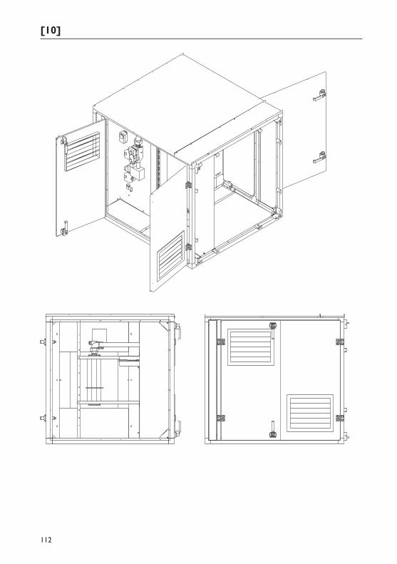
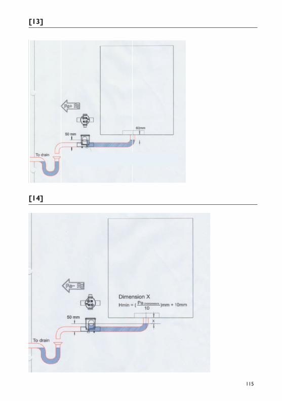
3.14 Siphon [13] [14]An air treatment unit usually contains components where condensation occurs. In such cases, appropriate measures must be applied to remove the condensation responsibly.A siphon must be connected to each condensation outlet or overflow connection. It is not permitted to connect several outlet pipes to a single, shared siphon.
– In case of overpressure the ball seat should be mounted 60mm under the lowest point of the drip tray. Remove the plug out of the bleed hole. [13]
– In case of underpressure the ball seat should be mounted below the lowest point of the drip tray according to the formula below. [14]
PaunderpressureH(mm) = ————————————— 10
The siphon pipe must not be connected directly to the sewage, but must be able to flow freely into the sewage. Always ensure that parts carrying the (condensed) water cannot freeze.
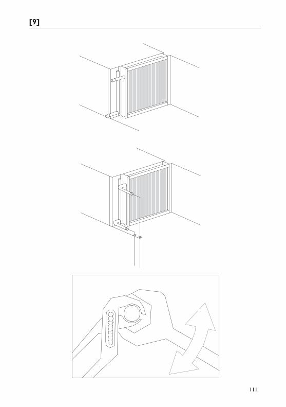
3.15 Drip catcher [8]If a drip catcher is fitted, it can be dismantled, and replaced after cleaning.
3.16 Shutting downAppliances must be shut down by skilled personnel. It is important to be familiar with the installation, operating and maintenance instructions as well as the maintenance instructions for air handling units and any peripherals in advance. Disregarding these instructions could result in danger to the personnel carrying out the work, and damage to the appliance.The air handling unit forms part of an air handling system.
For short periods of time.– Terminate the demand for heat/cooling.– Open the return air valve and close the outside air valve– Shut off all valves– Shut off the central heating pump– Shut off water and hand valves– Drain off any parts susceptible to freezing – Blow dry the heat exchanger and connections fully with air– Ventilate the unit fully until everything is dry.– Remove the water from the siphons– Switch off the mains switch and turn the unit off
10
For longer periods of time.Follow the points for shutting down the appliance for a short period.– Check that any filters have not become dirty. If they are dirty, it is recommended that they be
removed and replaced to prevent mould from forming.– De-tension the V-belts and the band(s).
4.0 Maintenance
4.1 GeneralThe appliance must be subjected to maintenance at least once a year, more often if necessary. If applicable, ask a qualified installer for maintenance advice. When carrying out maintenance, the appliance must have been shut down for an extended period. Make sure that you comply with all safety rules.
4.2 CleaningThe air treatment unit can be cleaned using commercially available cleaning agents. The cleaning agent manufacturer’s instructions must, however, be followed. Cleaning agents must not contain acids or other aggressive components.
4.3 Fan [4][5]During maintenance (at least 1x per year), check the V-belt(s) (if applicable) for the correct tension and evidence of wear and tear, and re-tension or replace if necessary. Always replace all the belts at the same time on multi-belt drives. Always check that the pulleys are aligned. Clean the fan wheel if necessary. Check the motor(s) and fan(s) for bearing noise, and replace bearings if necessary. It is recommended that protection against the belt breaking be installed. The adjustment criteria for new belts and pulleys are 80% of the nominal pressure. If the V-belt(s) are not sufficiently tensioned or are broken, pressure over the fan(s) will drop or be lost. The pressure switch installed will provide a signal, following which technical services need to apply appropriate measures.
4.4 Filters [6]Depending on the operating conditions, check the filters at short intervals, and replace if necessary. If the final pressure differential is exceeded, the filters should be changed. Consult the name plate on the filter compartment for further information. Various filters may be used depending on the unit’s use. Panel filters for low temperature, panel filters for high temperatures and/or bag filters. If the filters are located in the “cold” air flow, they may freeze over in the winter due to “frost”. A filter monitoring pressure switch (optional) can provide an early indication if the filter is dirty or blocked. If bag filters are used, make sure that the bags are inserted vertically. High temperature filters (filter class 4) should be used as far as possible with a Calflo. These filters are located after the heating section in order to prevent freezing. When replacing dirty filters, always wear suitable personal protective equipment. Care must be taken when removing dirty filters and fitting clean filters. Make sure filter frames are also correctly sealed. Dirty filters usually need to be treated as special waste.
4.5 Gravity shutter [7]The following maintenance activities should be carried out annually: Clean gravity shutters, never lubricate bearings (plastic). Check that gravity shutters are current. Check that servo motors fitted with end switches have the correct control functions.
EN
11
4.6 Flexible connectionCheck the flexible connection at least 1x per year.
4.7 Warm water, steam, cooler battery [9]Care should be taken when cleaning Cu/Al batteries. If the battery is dirty in the air direction, it can be blown clean in the opposite direction using compressed air or water. Ensure that the fins do not deform during cleaning. You should also prevent dust from entering the air handling unit and air duct.
4.8 Maintenance of gas-fired heat sourcesSee the installation and maintenance instructions supplied for the adjustment and maintenance of gas-fired heat sources. Warning: never switch off the electrical voltage until the air heater has cooled down completely.
4.9 Drip catcher [8]Maintenance: Check the drip catcher for contamination, damage and corrosion. Clean the drip catcher with compressed air, water steam or detergents containing soap. Check the water outlet and siphon/S-trap.
4.10 Sound attenuator If a sound attenuator is used, the wings cannot usually be removed from the attenuator section. Never clean the soft attenuating material with water. It is preferable to use a vacuum cleaner and/or a soft brush.
4.11 Heat recovery
Cross-flow heat exchangerUnder normal use of the air handling unit, the cross-flow heat exchanger would not be expected to become contaminated. If the air handling unit is used in extreme conditions, such as in welding areas, paint spraying locations, kitchens and the like, contamination may occur. Cleaning can be completed as follows: dust and other particles can be easily removed using a brush. Take care if using compressed air. Make sure that the element pack is not damaged. Greasy deposits can usually be removed with warm water. If necessary, suitable detergents may be used. It is recommended that any gravity shutters and servo motors be cleaned annually.
Rotating heat exchangerCheck that the wheel is rotating in the correct direction. Rotate the heat exchanger periodically during the summer months to utilize the exchanger’s self-cleaning capacity. A dirty surface may have a negative impact on the exchanger’s performance.

12
104
[1]
B
>B
105
>B
MAX. 60º
MAX. 60º
B
[2]
[3]
106
[4]
107
[5]
108
[6]
109
[7]
[8]
110
[9]
111
[10]
112
[11]
113
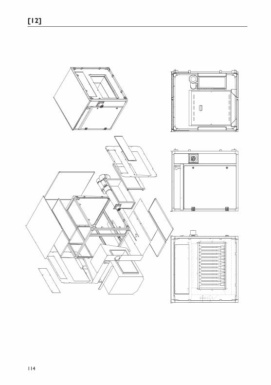
[12]
114
[13]
[14]
115
[15]
116
[16]
117
[17]
118
MARK BVBENEDEN VERLAAT 87-89VEENDAM (NEDERLAND)POSTBUS 13, 9640 AA VEENDAMTELEFOON +31(0)598 656600FAX +31 (0)598 [email protected]
MARK EIRE BVCOOLEA, MACROOMCO. CORK P12 W660 (IRELAND)PHONE +353 (0)26 45334FAX +353 (0)26 [email protected]
MARK BELGIUM b.v.b.a.ENERGIELAAN 122950 KAPELLEN (BELGIË/BELGIQUE)TELEFOON +32 (0)3 6669254FAX +32 (0)3 [email protected]
MARK DEUTSCHLAND GmbHMAX-PLANCK-STRASSE 1646446 EMMERICH AM RHEIN (DEUTSCHLAND)TELEFON +49 (0)2822 97728-0 TELEFAX +49 (0)2822 [email protected]
MARK POLSKA Sp. z o.oUL. JASNOGÓRSKA 2742-202 CZĘSTOCHOWA (POLSKA) PHONE +48 34 3683443 FAX +48 34 3683553 [email protected]
S.C. MARK ROMANIA S.R.L.STR. KOS KAROLY NR. 1 A540297 TARGU MURES (ROMANIA)TEL/FAX +40 (0)[email protected]
CERTIFICATION N°: 17.07.011 AIRSTREAM
CERTIFICATION N°: 17.07.011 AIRSTREAM
CERTIFICATION N°: 17.07.011 AIRSTREAM
CERTIFICATION N°: 17.07.011 AIRSTREAM