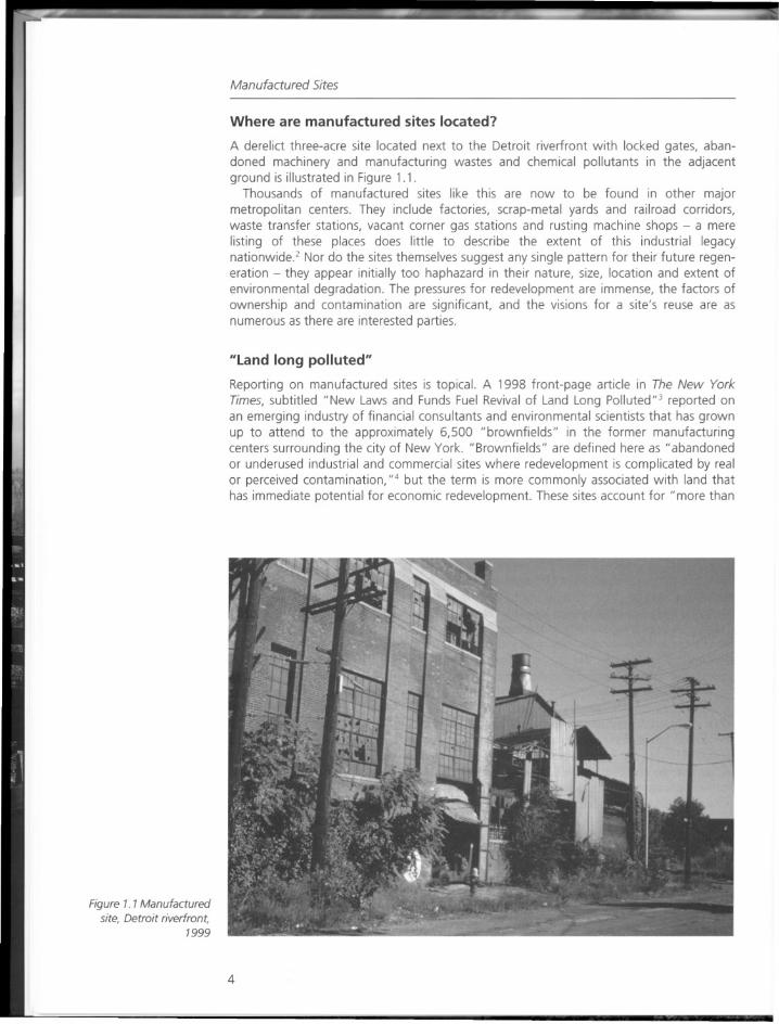
manufactured sites
DESCRIPTION
kjTRANSCRIPT


Par II
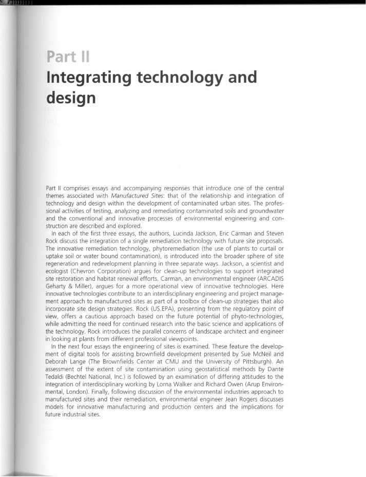
Integrating technology anddesign
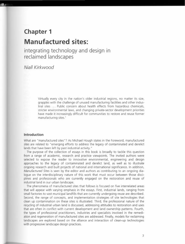
Part II comprises essays and accompanying responses that introduce one of the centralthemes associated with Manufactured Sites: that of the relationship and integration oftechnology and design within the development of contaminated urban sites. The professional activities of testing, analyzing and remediating contaminated soils and groundwaterand the conventional and innovative processes of environmental engineering and construction are described and explored.
In each of the first three essays, the authors, Lucinda Jackson, Eric Carman and StevenRock discuss the integration of a single remediation technology with future site proposals.The innovative remediation technology, phytoremediation (the use of plants to curtail oruptake soil or water bound contamination), is introduced into the broader sphere of siteregeneration and redevelopment planning in three separate ways. Jackson, a scientist andecologist (Chevron Corporation) argues for clean-up technologies to support integratedsite restoration and habitat renewal efforts. Carman, an environmental engineer (ARCADISGeharty & Miller), argues for a more operational view of innovative technologies. Hereinnovative technologies contribute to an interdisciplinary engineering and project management approach to manufactured sites as part of a toolbox of clean-up strategies that alsoincorporate site design strategies. Rock (US.EPA), presenting from the regulatory point ofview, offers a cautious approach based on the future potential of phyto-technologies,while admitting the need for continued research into the basic science and applications ofthe technology. Rock introduces the parallel concerns of landscape architect and engineerin looking at plants from different professional viewpoints.
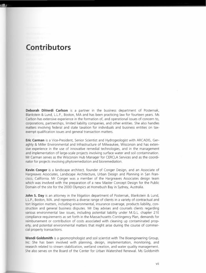
In the next four essays the engineering of sites is examined. These feature the development of digital tools for assisting brownfield development presented by Sue McNeil andDeborah Lange (The Brownfields Center at CMU and the University of Pittsburgh). Anassessment of the extent of site contamination using geostatistical methods by DanteTedaldi (Bechtel National, Inc.) is followed by an examination of differing attitudes to theintegration of interdisciplinary working by Lorna Walker and Richard Owen (Arup Environmental, London). Finally, following discussion of the environmental industries approach tomanufactured sites and their remediation, environmental engineer Jean Rogers discussesmodels for innovative manufacturing and production centers and the implications forfuture industrial sites.
Chapter 3
Beyond clean-up ofmanufactured sites:remediation, restoration and renewal ofhabitat
Lucinda Jackson
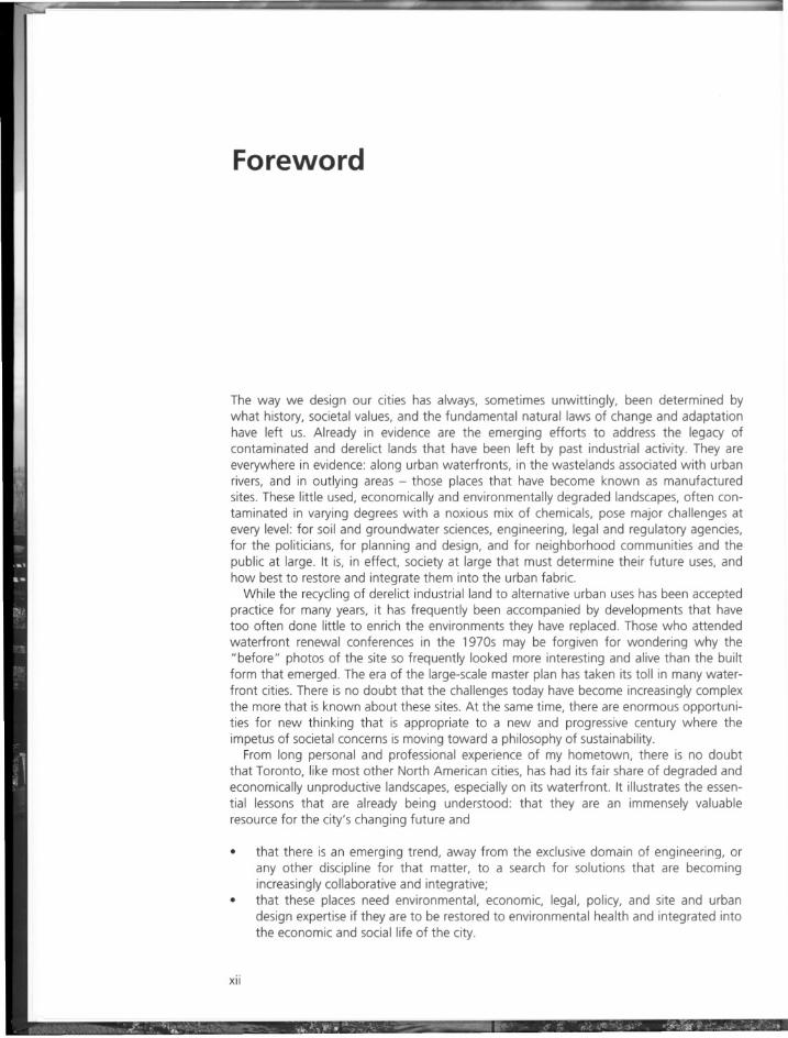
Introduction
Traditional ways of dealing with the clean-up of industrial sites have been to dig up existing contamination and haul it to a hazardous waste dump or entomb it in place with anasphalt or concrete cap. Now we recognize that we can go beyond traditional methods ofsite clean-up with the use of introduced plants to remediate contamination in place andsimultaneously restore and renew habitat. This use of vegetation opens up opportunitiesfor landscape architects, engineers, and biologists to work together to create new environments in former industrial settings.
There are diverse situations within the oil, gas, and chemical industries where site remediation may be desired: along pipelines, at refineries or chemical plants, at former service stations, or at abandoned production sites. These industries are located in various geographicaland environmental conditions around the world, from international to domestic, in tropicalto arid climates, centralized urban to rural sites, and in industrial to developing countries. Inthe environmental field, we look for ways to solve remediation issues while concentrating ona policy of pollution prevention, product stewardship, and resource conservation. It makesgood business sense to look for solutions that, while leading to clean-up and closure of asite, are cost-effective, environmentally sound, and aesthetically pleasing.
Two case studies are presented to illustrate technologies for remediation, restoration,and wildlife habitat renewal at industrial sites that could incorporate landscape design.Both sites formerly housed industrial businesses: the first case study site was a gasolinetransfer terminal; the second an oil refinery.
Case study 1: gasoline transfer terminal
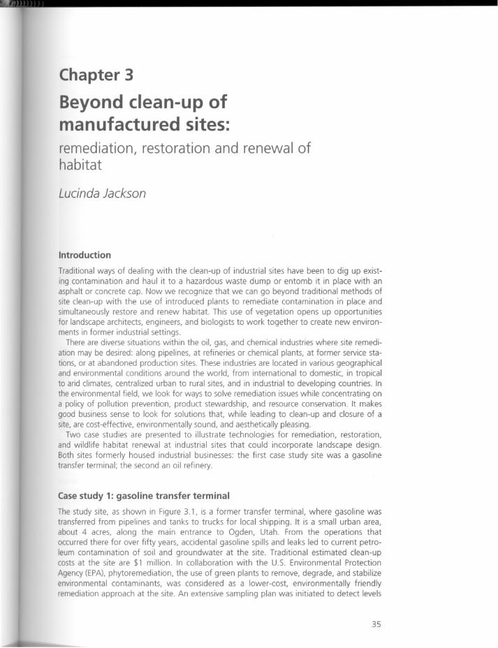
The study site, as shown in Figure 3.1, is a former transfer terminal, where gasoline wastransferred from pipelines and tanks to trucks for local shipping. It is a small urban area,about 4 acres, along the main entrance to Ogden, Utah. From the operations thatoccurred there for over fifty years, accidental gasoline spills and leaks led to current petroleum contamination of soil and groundwater at the site. Traditional estimated clean-upcosts at the site are $1 million. In collaboration with the U.S. Environmental Protection
Agency (EPA), phytoremediation, the use of green plants to remove, degrade, and stabilizeenvironmental contaminants, was considered as a lower-cost, environmentally friendlyremediation approach at the site. An extensive sampling plan was initiated to detect levels
35
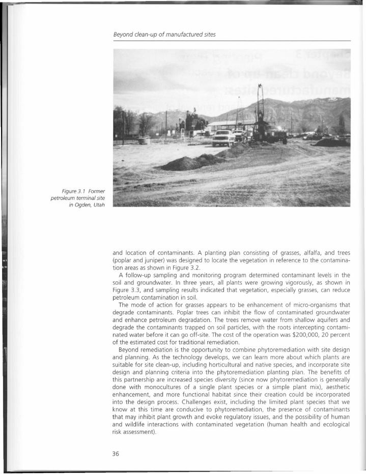
Figure 3. 1 Formerpetroleum terminal site
in Ogden, Utah
Beyond clean-up of manufactured sites
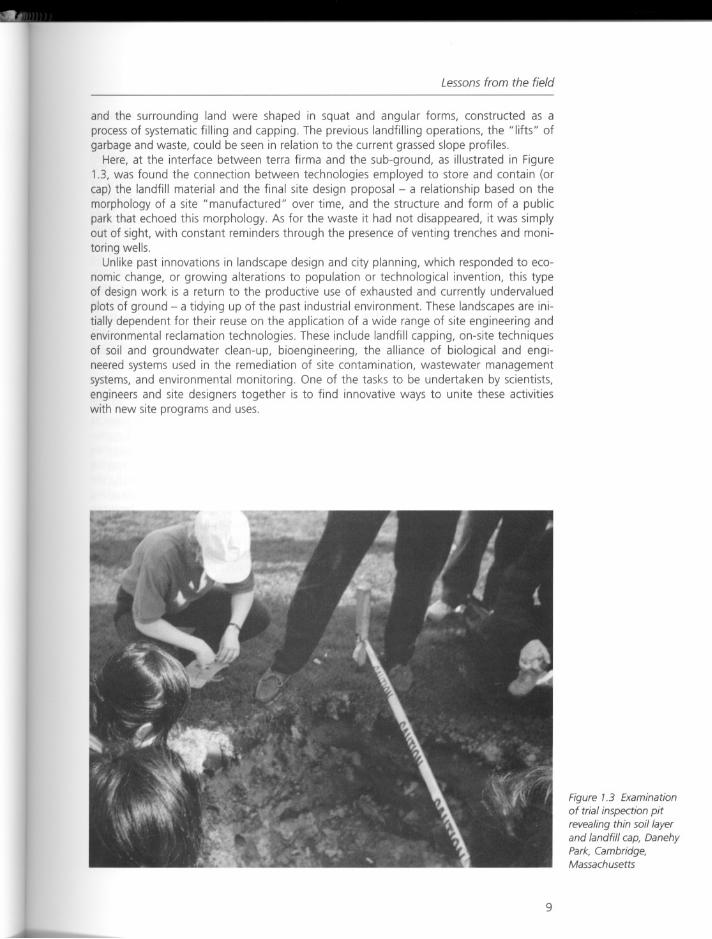
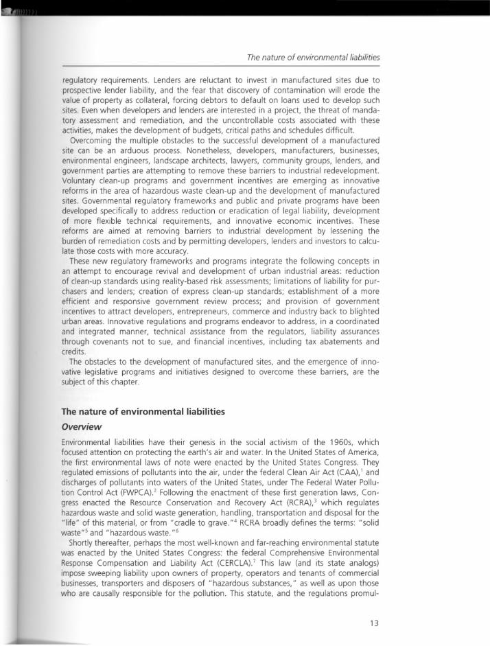
and location of contaminants. A planting plan consisting of grasses, alfalfa, and trees(poplar and juniper) was designed to locate the vegetation in reference to the contamination areas as shown in Figure 3.2.
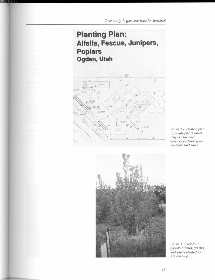
A follow-up sampling and monitoring program determined contaminant levels in thesoil and groundwater. In three years, all plants were growing vigorously, as shown inFigure 3.3, and sampling results indicated that vegetation, especially grasses, can reducepetroleum contamination in soil.
The mode of action for grasses appears to be enhancement of micro-organisms thatdegrade contaminants. Poplar trees can inhibit the flow of contaminated groundwaterand enhance petroleum degradation. The trees remove water from shallow aquifers anddegrade the contaminants trapped on soil particles, with the roots intercepting contaminated water before it can go off-site. The cost of the operation was $200,000, 20 percentof the estimated cost for traditional remediation.
Beyond remediation is the opportunity to combine phytoremediation with site designand planning. As the technology develops, we can learn more about which plants aresuitable for site clean-up, including horticultural and native species, and incorporate sitedesign and planning criteria into the phytoremediation planting plan. The benefits ofthis partnership are increased species diversity (since now phytoremediation is generallydone with monocultures of a single plant species or a simple plant mix), aestheticenhancement, and more functional habitat since their creation could be incorporatedinto the design process. Challenges exist, including the limited plant species that weknow at this time are conducive to phytoremediation, the presence of contaminantsthat may inhibit plant growth and evoke regulatory issues, and the possibility of humanand wildlife interactions with contaminated vegetation (human health and ecologicalrisk assessment).
36
Casestudy 7: gasoline transfer terminal
Planting Plan:Alfalfa, Fescue, Junipers,PoplarsOgden, Utah
-- -rr'
'"••
..
0..,.. . .• . .. -. .~--~ .•
~
..
37
Figure 3.2 Planting planto situate plants wherethey can be mosteffective in cleaning upcontaminated areas
Figure 3.3 Vigorousgrowth of trees, grasses,and alfalfa planted forsite clean-up
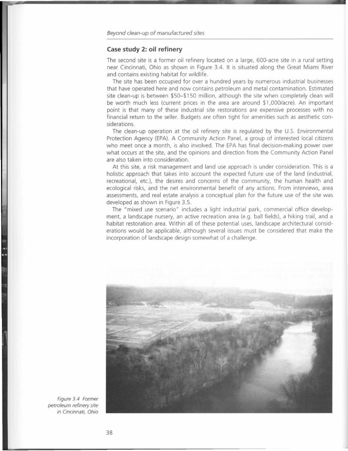
Figure 3.4 Former
petroleum refinery sitein Cincinnati, Ohio
Beyond clean-up of manufactured sites
Case study 2: oil refinery
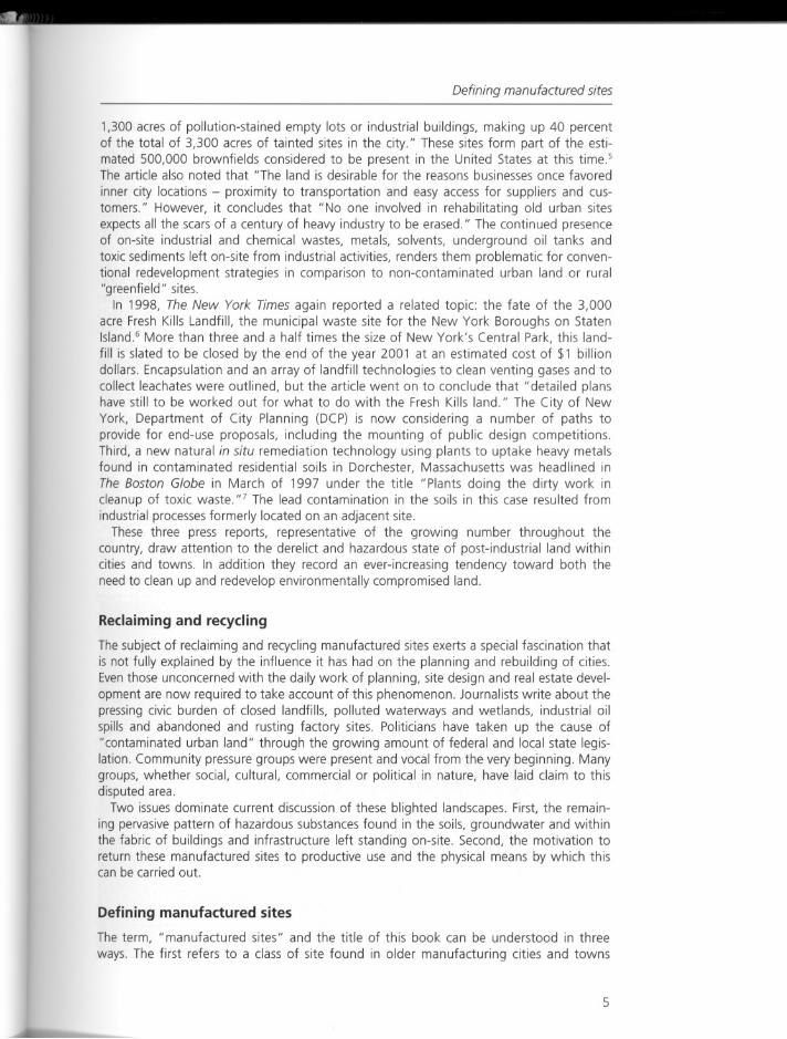
The second site is a former oil refinery located on a large, 600-acre site in a rural settingnear Cincinnati, Ohio as shown in Figure 3.4. It is situated along the Great Miami Riverand contains existing habitat for wildlife.
The site has been occupied for over a hundred years by numerous industrial businessesthat have operated here and now contains petroleum and metal contamination. Estimatedsite clean-up is between $50-$150 million, although the site when completely clean willbe worth much less (current prices in the area are around $1,000/acre). An importantpoint is that many of these industrial site restorations are expensive processes with nofinancial return to the seller. Budgets are often tight for amenities such as aesthetic considerations.
The clean-up operation at the oil refinery site is regulated by the u.s. EnvironmentalProtection Agency (EPA). A Community Action Panel, a group of interested local citizenswho meet once a month, is also involved. The EPA has final decision-making power overwhat occurs at the site, and the opinions and direction from the Community Action Panelare also taken into consideration.
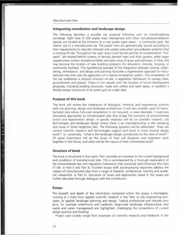
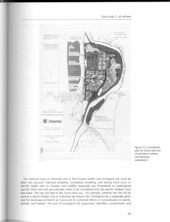
At this site, a risk management and land use approach is under consideration. This is aholistic approach that takes into account the expected future use of the land (industrial,recreational, etc.), the desires and concerns of the community, the human health andecological risks, and the net environmental benefit of any actions. From interviews, areaassessments, and real estate analysis a conceptual plan for the future use of the site wasdeveloped as shown in Figure 3.5.
The "mixed use scenario" includes a light industrial park, commercial office development, a landscape nursery, an active recreation area (e.g. ball fields), a hiking trail, and ahabitat restoration area. Within all of these potential uses, landscape architectural considerations would be applicable, although several issues must be considered that make theincorporation of landscape design somewhat of a challenge.
38
Casestudy 2: oil refinery
r
\t. t'rt l t· (l'n.tno
( UlI1l'plu,.1 \1,1 "'r 1'1,10
•••• Chevron
The common issue at industrial sites is that human health and ecological risk must betaken into account. Intensive sampling, conceptual modeling, and testing must occur toidentify health risks to humans and wildlife (especially any threatened or endangeredspecies).Both soils and groundwater need to be considered and site-specific analysis musttake place. The risks are tied to the future land use - for example, whether the site will beused as a school (higher risk) or industrial site (lower risk), Ecological risk is especially pertinent for landscape architects as it accounts for potential effects of contaminants on plants,animals, and habitat. The tool of ecological risk assessment identifies contaminants and
39
Figure 3.5 Conceptualplan for future land useof petroleum refinerysite followingremediation
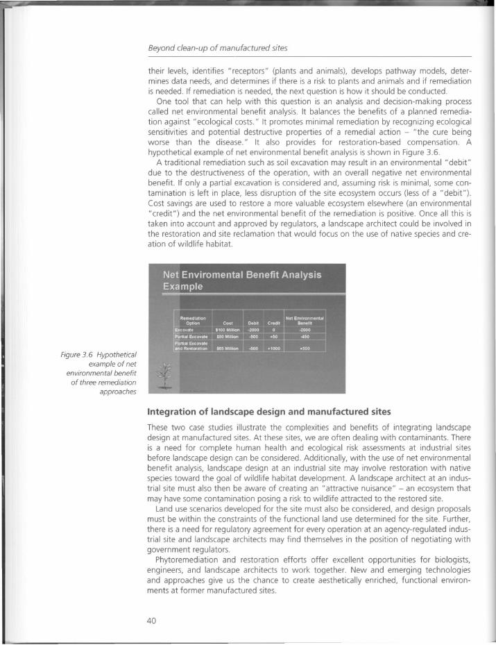
Figure 3.6 Hypotheticalexample of net
environmental benefitof three remediation
approaches
Beyond clean-up of manufactured sites
their levels, identifies "receptors" (plants and animals), develops pathway models, determines data needs, and determines if there is a risk to plants and animals and if remediationis needed. If remediation is needed, the next question is how it should be conducted.
One tool that can help with this question is an analysis and decision-making processcalled net environmental benefit analysis. It balances the benefits of a planned remediation against" ecological costs." It promotes minimal remediation by recognizing ecologicalsensitivities and potential destructive properties of a remedial action - "the cure beingworse than the disease." It also provides for restoration-based compensation. Ahypothetical example of net environmental benefit analysis is shown in Figure 3.6.
A traditional remediation such as soil excavation may result in an environmental "debit"due to the destructiveness of the operation, with an overall negative net environmentalbenefit. If only a partial excavation is considered and, assuming risk is minimal, some contamination is left in place, less disruption of the site ecosystem occurs (less of a "debit").Cost savings are used to restore a more valuable ecosystem elsewhere (an environmental"credit") and the net environmental benefit of the remediation is positive. Once all this istaken into account and approved by regulators, a landscape architect could be involved inthe restoration and site reclamation that would focus on the use of native species and creation of wildlife habitat.
Integration of landscape design and manufactured sites
These two case studies illustrate the complexities and benefits of integrating landscapedesign at manufactured sites. At these sites, we are often dealing with contaminants. Thereis a need for complete human health and ecological risk assessments at industrial sitesbefore landscape design can be considered. Additionally, with the use of net environmentalbenefit analysis, landscape design at an industrial site may involve restoration with nativespecies toward the goal of wildlife habitat development. A landscape architect at an industrial site must also then be aware of creating an "attractive nuisance" - an ecosystem thatmay have some contamination posing a risk to wildlife attracted to the restored site.
Land use scenarios developed for the site must also be considered, and design proposalsmust be within the constraints of the functional land use determined for the site. Further,
there is a need for regulatory agreement for every operation at an agency-regulated industria/ site and landscape architects may find themselves in the position of negotiating withgovernment regulators.
Phytoremediation and restoration efforts offer excellent opportunities for biologists,engineers, and landscape architects to work together. New and emerging technologiesand approaches give us the chance to create aesthetically enriched, functional environments at former manufactured sites.
40
Habitat
Response
Remediation, design, and environmental benefit
Industry: regulations and innovations
The Chevron Corporation (in the two case studies discussed) is exploring nontraditionalmethods of site remediation. This may reveal a paradigm shift occurring in big business - ashift from mechanically cleaning a site to biologically based solutions. However, as Jacksonnotes, remediation is undertaken when regulations mandate it, and innovative technologies may be primarily employed when found to be less expensive than traditionalmethods. Regulations and incentives alone will not create healthy ecosystems - they haveto be a priority of a culture's value system.
Phytoremediation
The essay highlights the fact that collecting pertinent site data is critical to a successfulremediation. In the urban case study site, a sampling plan was initiated to detect levelsand location of contaminants. Follow-up questions to this include: What are the criteriaone uses to sample a site? For example, does a consistent grid need to be placed over thesite where samples are then taken and mapped) Does one research the history of the siteto determine previous land use, vegetation, and groundwater flows? In both of the casestudies discussed, Chevron worked with the EPA. Did the EPA set the criteria for samplinga site, the level it must be remediated to, and establish the monitoring program?
Once the contaminants on the site are understood, if phytoremediation is to beemployed, one must determine which plants are best for remediating the particular site'ssoil and/or water. And, more precisely, which plants work best for specific types of contaminants and why. The essay states that grasses, alfalfa, and trees were utilized, but it wasnot clear if this clean-up effort was designed to be experimental, or simply used availableresearch. The project has been monitored to determine its effectiveness at cleansing soiland groundwater, but one may ask how its effectiveness was measured. Were the plantsharvested and toxins extracted and weighed? Was the soil sampled at successive intervals?
The second case study, which is a master plan for a mixed use development, highlightsthe importance of data collection on contaminants. Planning future land uses is tied tounderstanding the contaminants present, the clean-up options, and determining necessarylevels of remediation for the expected land use. This underscores the need to map andrecord contaminants and clean-up; as land uses typically change over time, additionalremediation could be required for a future land use.
Habitat
What is the relationship between plants for remediating contamination and the creationof habitat? Does one employ phytoremediation for cleansing a site, then when it is cleanseek to replace habitat? Once plants are planted and growing, there will be microbialaction, insects, and on up the food chain, creating habitat whether intended as such ornot. The question of birds and mammals eating contaminated plants was raised in theessay:what is the effect of this in the ecosystem? And what are the potential dangers tohuman health? It seems clear that more research needs to be done in this area.
The creation of habitat on a site must be seen as part of larger systems of climate, landform, vegetation, and water. It is essential to understand what type of habitat you aretrying to restore. Understanding the landscape at a much larger scale than the actual site
41
Beyond clean-up of manufactured sites
is critical. For example, some types of bird habitat, and that of large mammals, must takeinto account many hundreds of acres. The location of nearby wildlife preserves, stateforests, lakes, etc. all have a relationship to the fragmented habitat that you may beseeking to renew. These are critical issues far beyond the notion of simply planting nativeplants.
Remediation, values, and master planning
The second case study site was described as being a hundred years old, and whileindustry may have been present on the site for a hundred years, the site is of coursevastly older than that. It may be simply a choice of words, or it may reveal how differently land is looked at depending on one's point of view. The essay states that remediating this site will cost more than the land will be worth when it is clean. Thishighlights how a financially oriented value system views land as a commodity, whilean ecological value system values the healthy functioning of the ecosystem.
The essay introduces the concept of a "net environmental benefit analysis" which isdesigned to balance the planned remediation against ecological costs, stating that sometimes minimal remediation is less disruptive to the ecosystem than complete remediation.This minimal remediation saves money that can be invested in restoring a "more valuableecosystem." What is a "more valuable ecosystem"? More valuable to whom and why?And who makes these decisions?
A master plan for the second case study site has been developed by the EPA, Chevron,and a community action panel of interested local citizens. This approach was described asholistic, yet it is unclear which design professionals, if any, were involved in this plan forthe site as a mixed use development. Jackson states, "Within all these potential uses, landscape architectural considerations would be applicable, although several issues must beconsidered that make the incorporation of landscape design somewhat of a challenge."Rather than being called in at the end of a project to "landscape" the site, landscapearchitects are the ideal professionals to evaluate the site from a variety of perspectives andeffectively design the mixed use scenario (if appropriate) that she describes, and to coordinate with government, business, and citizen groups.
Jackson notes that there are additional implications for designers as more becomesknown about phytoremediation and its cleansing properties and aesthetic qualities. Phytoremediation species are typically planted in monocultures, but as more becomes knownabout which plants clean what contaminants, the designer will be able to choose between(and mix) several plant species, enlarging the range of design solutions. Diversity of plantspecies also enhances habitat creation. Some plants used for phytoremediation, such aspoplar trees, may remain long term on the site, thereby providing not just cleansing benefits but ongoing visual impact.
It is clear that industry, as demonstrated by the Chevron Corporation, is interested inexpanding its range of remediation options. Industry and universities, or other researchinstitutions, may benefit by collaborating on experimental sites to determine larger plantpalettes for remediation, and to monitor the effectiveness of selected plants - especially asa huge range of sites worldwide may need attention. Including designers in the processfrom the beginning would provide valuable expertise to the remediation team.
42
Chapter 4
From laboratory to landscape:a case history and possible future directionfor phyto-enhanced soil bioremediation
Eric Carman
Introduction
There is an emerging trend in the environmental industry toward identification of theimportant role of natural processes in mitigating environmental contamination and implementing more passive remedial technologies. As this trend evolves, natural processes willbe integrated with more conventional remedial technologies that are commonly used inthe industry. This essay presents a broad overview of bioremediation and phytoremediation, two innovative technologies that harness natural processes and can easily be integrated with more conventional remedial technologies. A case history of a phytoremediationproject and possible future directions for phytoremediation are also discussed.
Bioremediation is a relatively established remedial technology. It consists of the stimulation of micro-organisms to break down organic contaminants into simpler, often morebenign compounds. Generally, micro-organisms that are naturally present in soil andgroundwater systems (indigenous micro-organisms) are used in bioremediation applications. Bioremediation has the advantage that it can be used either ex situ (above ground)or in situ (in place).
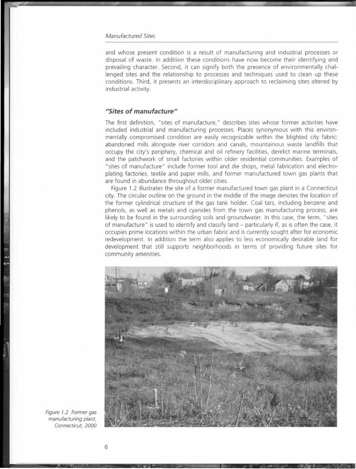
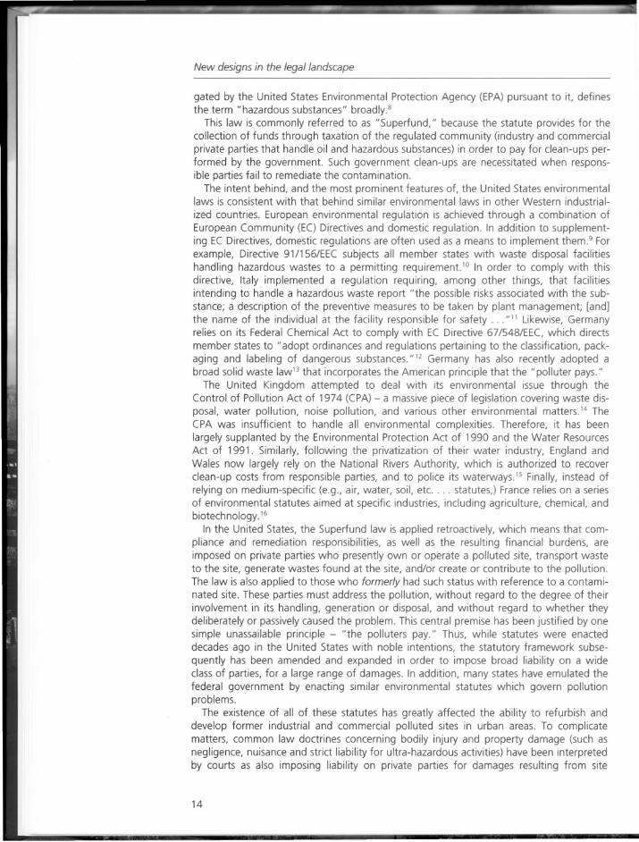
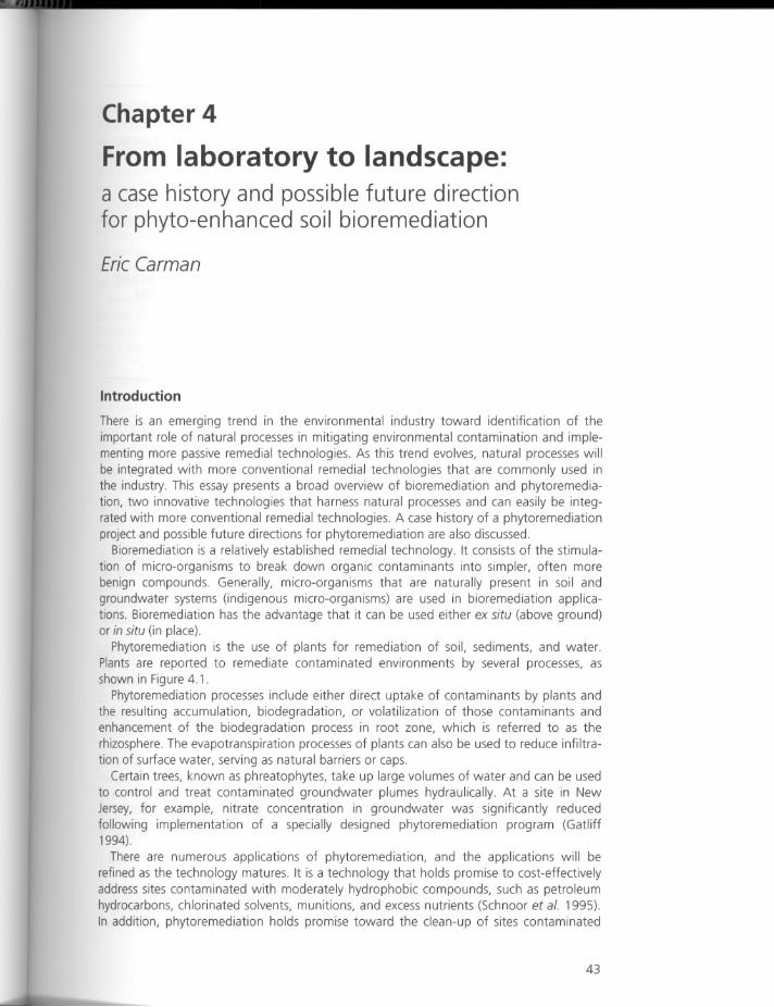
Phytoremediation is the use of plants for remediation of soil, sediments, and water.Plants are reported to remediate contaminated environments by several processes, asshown in Figure 4.1.
Phytoremediation processes include either direct uptake of contaminants by plants andthe resulting accumulation, biodegradation, or volatilization of those contaminants andenhancement of the biodegradation process in root zone, which is referred to as therhizosphere. The evapotranspiration processes of plants can also be used to reduce infiltration of surface water, serving as natural barriers or caps.
Certain trees, known as phreatophytes, take up large volumes of water and can be usedto control and treat contaminated groundwater plumes hydraulically. At a site in NewJersey, for example, nitrate concentration in groundwater was significantly reducedfollowing implementation of a specially designed phytoremediation program (Gatliff1994).
There are numerous applications of phytoremediation, and the applications will berefined as the technology matures. It is a technology that holds promise to cost-effectivelyaddress sites contaminated with moderately hydrophobic compounds, such as petroleumhydrocarbons, chlorinated solvents, munitions, and excess nutrients (Schnoor et al. 1995).In addition, phytoremediation holds promise toward the clean-up of sites contaminated
43
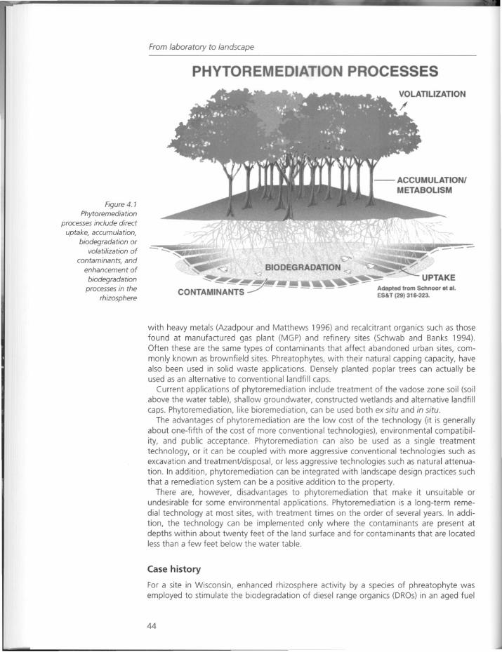
Figure 4. 1
Phytoremediationprocesses include direct
uptake, accumulation,biodegradation or
volatilization of
contaminants, andenhancement of
biodegradationprocesses in the
rhizosphere
From laboratory to landscape
PHYTOREMEDIATION PROCESSES
---/r"'G BIODEGRADATION' ~
""0 - UPTAKE-...;:::- ~~A ~-CONTAMINANTS-7- - - - - - ~ =- Adapted from Schnooretal.ES&T (29) 318-323.
with heavy metals (Azadpour and Matthews 1996) and recalcitrant organics such as thosefound at manufactured gas plant (MGP) and refinery sites (Schwab and Banks 1994).Often these are the same types of contaminants that affect abandoned urban sites, commonly known as brownfield sites. Phreatophytes, with their natural capping capacity, havealso been used in solid waste applications. Densely planted poplar trees can actually beused as an alternative to conventional landfill caps.
Current applications of phytoremediation include treatment of the vadose zone soil (soilabove the water table), shallow groundwater, constructed wetlands and alternative landfillcaps. Phytoremediation, like bioremediation, can be used both ex situ and in situ.
The advantages of phytoremediation are the low cost of the technology (it is generallyabout one-fifth of the cost of more conventional technologies), environmental compatibility, and public acceptance. Phytoremediation can also be used as a single treatmenttechnology, or it can be coupled with more aggressive conventional technologies such asexcavation and treatment/disposal, or less aggressive technologies such as natural attenuation. In addition, phytoremediation can be integrated with landscape design practices suchthat a remediation system can be a positive addition to the property.
There are, however, disadvantages to phytoremediation that make it unsuitable orundesirable for some environmental applications. Phytoremediation is a long-term remedial technology at most sites, with treatment times on the order of several years. In addition, the technology can be implemented only where the contaminants are present atdepths within about twenty feet of the land surface and for contaminants that are locatedless than a few feet below the water table.
Case history
For a site in Wisconsin, enhanced rhizosphere activity by a species of phreatophyte wasemployed to stimulate the biodegradation of diesel range organics (DROs) in an aged fuel
44
Case history
oil spill. The objective of the project is to remediate soil and fill materials contaminatedwith DROs within four identified soil hot spots at the facility to below 1,000 mg/kg DROs,as required by the Wisconsin Department of Natural Resources (WDNR). Excavation andtreatment of the soil materials was not a preferred option, based on the potential costsassociated with segregating construction debris from soil and the risks inherent in excavating at a facility with a long operational history.
Operations began at this site in the early 1900s. A heterogeneous mixture of fill materialwas used to extend the property boundary west to an adjacent river. During the late1970s, a section of below-ground piping transferring NO.2 fuel oil failed, resulting in asubsurface release. Approximately 15,000 gallons (56,800 liters) of fuel oil were recoveredfrom shallow trenches installed at the site, and concentrations of hydrocarbon constituents in groundwater are currently below regulatory standards.
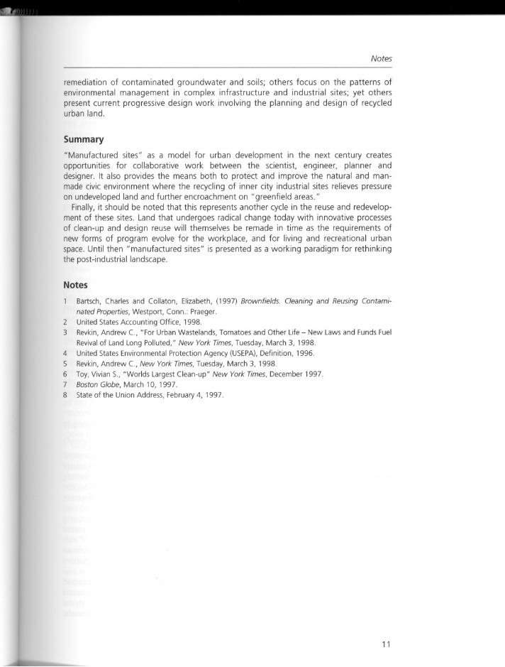
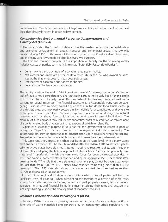
Investigations at the site have determined that highly contaminated soil (concentrationsgreater than 1,000 ppm DROs) remain in four hot spots at the site as shown in Figure 4.2.Three of the hot spots (Hot Spots 1, 2 and 4) are below a hard-packed gravel equipment storage area, and a fourth (Hot Spot 3) is located below a vegetated area along theriver.
Figure 4.2 Siteschematic and locations
of the four soil hot spots
DROs = Diesel Range OrganicsMW-1.
HOTSPOT~ ~
GMTP3 ~
o MW·6 ~
LEGEND
MW. Monitoring Well
GMTP4- Test Pit Completed byGeraghty & MillerD Concentration ofDROs >1000 mg/kg
a 150 300
SCALE IN FEET
MW-3 •
HOT SPOT 3
MW-5
~~~
HOTSPOT4~MW-2 •
45
From laboratory to landscape
Materials and methods
Soil samples were collected and analyzed from 1994 to 1996 to determine initial concentrations of DROs in soil, microbial population densities and respiration rates, and for performing accelerated bioventing tests. Accelerated bioventing tests were performed on twosoil samples (Soil Samples GMTP3/4-5 and GMTP4/4-5) for a 24-week period with sacrificing of sample aliquots for DROs or respirometry testing at Weeks 0, 2, 4, 6, 13 and 24.Soil samples were also collected from Hot Spot 2 and Hot Spot 3 to determine phyto-toxiceffects on tree root development, concentrations of agronomic constituents of interest,and to select optimal tree species.
Results
Concentrations of the DROs exhibit a wide degree of variability, and the highest concentrations were present in the zone above the shallow water table. Concentrations of DROs rangedfrom 40 mglkg to 5,000 mglkg. The results from the microbial enumerations indicated that aviable population of microbes capable of degrading fuel oil was indigenous to soil at the facility. Populations of heterotrophs ranged from 1.1 x 10⁵ dulg to 4.1 x 10⁶ dulg and populations of diesel fuel-degrading microbes ranged from 5.7 x 10³ du/g to 9.5 x 10⁵ dulg.
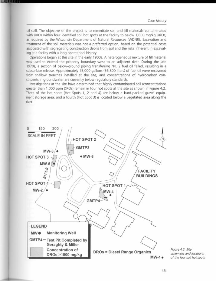
The results of DROs analyses performed on aliquots of Soil Samples GMTP3/4-5 andGMTP4/4-5 are presented in Figure 4.3.
After an initial apparent increase in DRO concentrations between Weeks 2 and 4, an overall40 to 90 percent decrease in DROs was observed over the course of the 24-week bioventingstudy. The variability in the concentration of the DROs initially observed over the first severalweeks of the study is primarily attributed to sampling variability resulting from the extremelyheterogeneous distribution of the petroleum hydrocarbons observed in soil at the site.
Based on the results of this study, in situ bioventing and phytoremediation wereselected as appropriate treatment alternatives for full-scale site remediation. Phytoremediation was then selected as the alternative, based on its lower costs for implementing andmonitoring. Both hybrid poplars and willows exhibited good aerial growth during the rootdevelopment portion of the agronomic assessment. Willows, however, demonstrated amore pronounced tendency to establish rooting within the DROs-contaminated soil andwere selected for planting in the hot spots.
(a)
L•••••
o DupUUl. $•••••• AtI~c •••••• ofltM,.oSamptn
• S"Il.S •••• (•••.•••••• rtOl.".",.ed)
2510 15 20Time (Weeks After SlDrt)
(b)
5
o
oo
e3000Do
.e 2500•c:.ll 2000!~ 1500l!8 1000
~ 500
2S5 10 15 20TIME (Weeks Afler SlDrt)
e 16! 14
~ _12
.g ~10
i ~8
~ ~ 60_o 4
~ 2
oo
Figure 4.3 OROconcentration over time
in biovented soil for (a)
Soil Sample GMTP3/4-5and for (b) Soil Sample
GMTP4/4-5
46
Tree planting
Tree planting
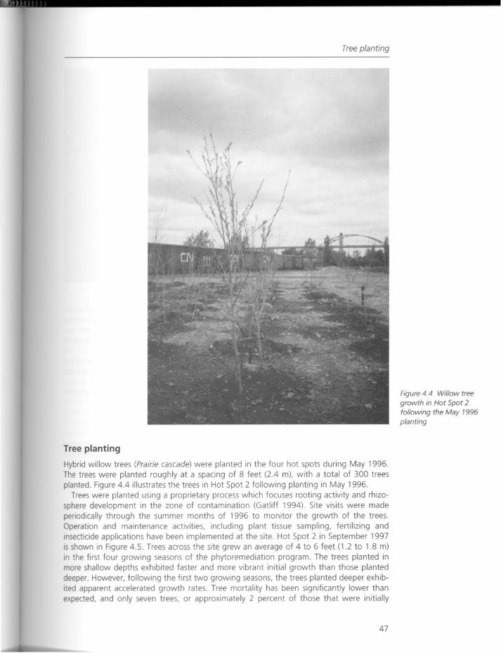
Hybrid willow trees (Prairie cascade) were planted in the four hot spots during May 1996.The trees were planted roughly at a spacing of 8 feet (2.4 m), with a total of 300 treesplanted. Figure 4.4 illustrates the trees in Hot Spot 2 following planting in May 1996.
Trees were planted using a proprietary process which focuses rooting activity and rhizosphere development in the zone of contamination (Gatliff 1994). Site visits were madeperiodically through the summer months of 1996 to monitor the growth of the trees.Operation and maintenance activities, including plant tissue sampling, fertilizing andinsecticide applications have been implemented at the site. Hot Spot 2 in September 1997is shown in Figure 4.5. Trees across the site grew an average of 4 to 6 feet (1.2 to 1.8 m)in the first four growing seasons of the phytoremediation program. The trees planted inmore shallow depths exhibited faster and more vibrant initial growth than those planteddeeper. However, following the first two growing seasons, the trees planted deeper exhibited apparent accelerated growth rates. Tree mortality has been significantly lower thanexpected, and only seven trees, or approximately 2 percent of those that were initially
47
Figure 4.4 Willow treegrowth in Hot Spot 2following the May 1996planting
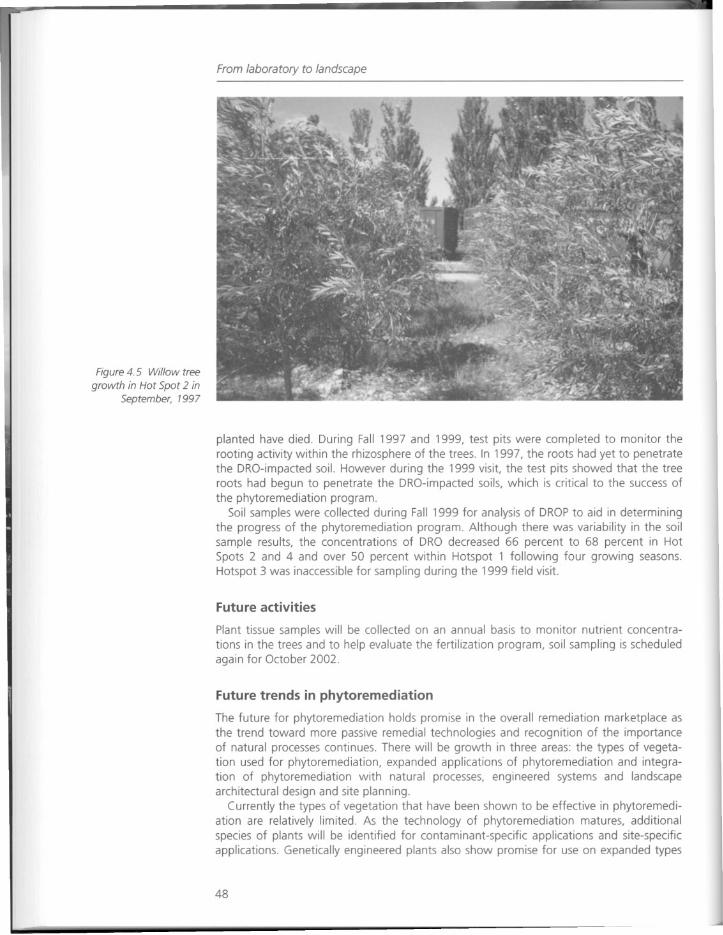
Figure 4.5 Willow treegrowth in Hot Spot 2 in
September, 1997
From laboratory to landscape
planted have died. During Fall 1997 and 1999, test pits were completed to monitor therooting activity within the rhizosphere of the trees. In 1997, the roots had yet to penetratethe DRO-impaded soil. However during the 1999 visit, the test pits showed that the treeroots had begun to penetrate the DRO-impacted soils, which is critical to the success ofthe phytoremediation program.
Soil samples were collected during Fall 1999 for analysis of DROP to aid in determiningthe progress of the phytoremediation program. Although there was variability in the soilsample results, the concentrations of DRO decreased 66 percent to 68 percent in HotSpots 2 and 4 and over 50 percent within Hotspot 1 following four growing seasons.Hotspot 3 was inaccessible for sampling during the 1999 field visit.
Future activities
Plant tissue samples will be collected on an annual basis to monitor nutrient concentrations in the trees and to help evaluate the fertilization program, soil sampling is scheduledagain for October 2002.
Future trends in phytoremediation
The future for phytoremediation holds promise in the overall remediation marketplace asthe trend toward more passive remedial technologies and recognition of the importanceof natural processes continues. There will be growth in three areas: the types of vegetation used for phytoremediation, expanded applications of phytoremediation and integration of phytoremediation with natural processes, engineered systems and landscapearchitectural design and site planning.
Currently the types of vegetation that have been shown to be effective in phytoremediation are relatively limited. As the technology of phytoremediation matures, additionalspecies of plants will be identified for contaminant-specific applications and site-specificapplications. Genetically engineered plants also show promise for use on expanded types
48
References
of contaminants. Engineered phyto-treatment units (EPTUs, similar to biopiles), constructed wetlands and vegetative caps will be used on a wider range of sites. Phytoremediation will be used increasingly as a remedial alternative for brownfields redevelopment,based on its aesthetic appeal and low cost.
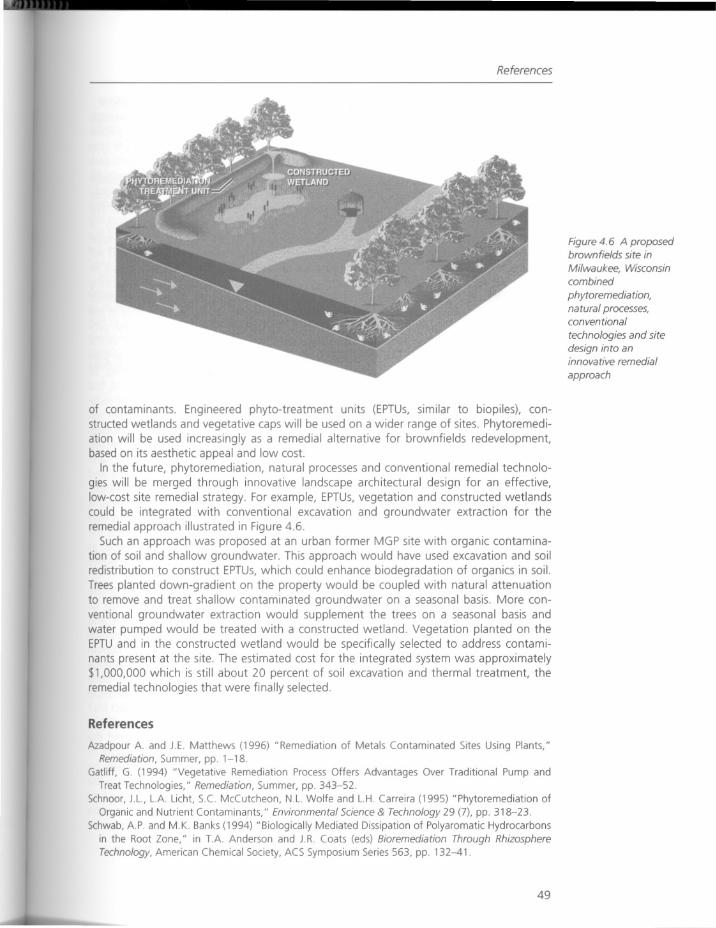
In the future, phytoremediation, natural processes and conventional remedial technologies will be merged through innovative landscape architectural design for an effective,low-cost site remedial strategy. For example, EPTUs,vegetation and constructed wetlandscould be integrated with conventional excavation and groundwater extraction for theremedial approach illustrated in Figure 4.6.
Such an approach was proposed at an urban former MGP site with organic contamination of soil and shallow groundwater. This approach would have used excavation and soilredistribution to construct EPTUs,which could enhance biodegradation of organics in soil.Trees planted down-gradient on the property would be coupled with natural attenuationto remove and treat shallow contaminated groundwater on a seasonal basis. More conventional groundwater extraction would supplement the trees on a seasonal basis andwater pumped would be treated with a constructed wetland. Vegetation planted on theEPTUand in the constructed wetland would be specifically selected to address contaminants present at the site. The estimated cost for the integrated system was approximately$1,000,000 which is still about 20 percent of soil excavation and thermal treatment, theremedial technologies that were finally selected.
References
Azadpour A. and J.E. Matthews (1996) "Remediation of Metals Contaminated Sites Using Plants,"Remediation, Summer, pp. 1-18.
Gatliff, G. (1994) "Vegetative Remediation Process Offers Advantages Over Traditional Pump andTreat Technologies," Remediation, Summer, pp. 343-52.
Schnoor, J.L., LA Licht, S.c. McCutcheon, N.L. Wolfe and L.H. Carreira (1995) "Phytoremediation ofOrganic and Nutrient Contaminants," Environmental Science & Technology 29 (7), pp. 318-23.
Schwab, A.P. and M.K. Banks (1994) "Biologically Mediated Dissipation of Polyaromatic Hydrocarbons
in the Root Zone," in T.A. Anderson and J.R. Coats (eds) Bioremediation Through RhizosphereTechnology. American Chemical Society, ACS Symposium Series 563, pp. 132-41.
49
Figure 4.6 A proposedbrown fields site in
Milwaukee, Wisconsincombined
phytoremediation,natural processes,conventional
technologies and sitedesign into aninnovative remedial
approach
From laboratory to landscape
Response
Remediation as engineering?
Arising from a relatively new area of research science, phyto-enhanced soil bioremediationprojects may be entering a new phase. In this evolution, the landscape architect and otherspecialists can playa greater role in developing project goals and design criteria. Theresults of this collaborative design process may lead to a fresh reinterpretation ofneglected contaminated sites for a wide range of users. As an integrated team modelevolves and design teams become more diverse, the technology of phyto-enhanced soilbioremediation will have a dialogue with the art of landscape design. Vegetation will beused to cleanse the soil and at the same time to form spatial relationships, mark activityareas and circulation routes, create aesthetic compositions and forms, and provide habitatfor wildlife. These technical and design considerations will be strong determinants at theoutset when project goals are initially determined. And we may foresee remediation projects that bear a closer resemblance to the landscapes of Capability Brown than to theplantation grid, as so many do today. The design approach for future remediation sitesmay, in time, go well beyond references to traditional park design, incorporating, asCarman points out, a natural systems approach that not only addresses toxin removal, butcreates sustainable new habitats. In combination as well with new water treatment tech
nologies (see Wendi Goldsmith, Chapter 12, this volume), phytoremediation strategies willsurely offer more complex and ecologically diverse solutions. The use of natural processeswill call for a longer view in the analysis of costs, effectiveness, and benefits, especiallywhen compared to more conventional technologies such as artificial capping, andpumping and drainage collection treatments. In addition to the ecological benefits andlong-term lower costs, Carman points to a greater public acceptance of phytoremediation.Presumably "green" technology on a site is viewed as an aesthetically pleasing solution. Anote of caution must be raised. If phyto-enhanced soil bioremediation technology is perceived as an aesthetically and psychologically acceptable solution, might we also run therisk of developing a public complacency toward future contamination? In other words, aswe treat toxic sites with new" green" technologies do we run the risk of losing the publicvigilance against future contamination?
While this essay raises a number of compelling reasons for the diversification of thecurrent technologies and practices through an interdisciplinary approach, a number ofquestions, both technical and design-related, need further clarification if current andfuture designers are to embrace, contribute to, and expand upon the obvious potentialinherent in this area of practice. As we consider park-like uses and the inclusion of humanactivity into these sites a number of questions remain as to the degree of environmentaland human safety of phytoremediation. As the tree roots absorb toxins in the soil, thesetoxins would apparently be harbored in the tree. Do dangerous exposures remain possiblefor children or wildlife in the dead wood and leaf litter? What about pollen and insect life?The migration of these toxins and their persistence in the food web will need to be determined. Are there sites with levels and concentrations of contaminants that exceed the
capacity of phytoremediation? In addition, will these projects result in a monoculture oftree species, a culture with minimal diversity, or can a mixed-species approach bedeveloped that offers a rich and diverse ecology? Design considerations would look for thewidest possible palette of plant materials, including shrubs and perennials from which todraw and apply effectively in remediation projects. These questions will clearly requirefurther research and the answers will be critical if the uses of these projects are to beexpanded.
50
Response
While cost-effectiveness and efficiency will remain driving determinants in addressingdisturbed sites, the potential for multiple and long-term benefits including parkland,wildlife sanctuaries and greenbelts will win strong advocacy. In the early stages these projects should become design laboratories, where process and results are evaluated withdata created for further refinement and integration in subsequent projects. Environmentaldesigners will find the greatest potential in the combination of various models of constructed wetlands, phytoremediation and conventional remediation technologies, integrated in a multi-modeled approach to site remediation. From the evidence suggested inthis essay, it seems clear that future efforts in the area of phyto-enhanced soil remediationwill follow the model of integrated design teams, teams that will include scientists, designers, ecologists and other specialists. How these projects, in process and product, will differfrom the traditional engineered projects is not clear.
While the scientists, as evidenced during this conference, are eager to engage thedesigners, designers will need to become more knowledgeable of the latest technologies,so they can bring informed proposals to the table. Clearly this dialogue will need to takepart at many levels, and as the disciplines gather around the table, scientists must educatedesigners and designers must engage scientists about the creative process. As the complexion of the teams changes, so too will the working process as programming andaesthetic and spatial considerations are integrated into the planning.
51
Chapter 5
Phytoremediation:integrating art and engineering throughplanting
Steven Rock
Introduction
Landscape Architecture and Remediation Engineering are related fields, united bycommon areas of endeavor, yet they have strikingly different languages, techniques, andhabits of thought. A professional from each discipline may stand at the same place, viewthe same site, and describe the site with different words that express a vastly differentexperience and professional perspective. While the landscape architect may interpretparticular qualities of the land shaping the site through its contours and artifacts, theremediation engineer is concerned with groundwater flows and soil contaminant concentrations, human health and the environment.
What unites the fields is the fact that they often work on the same site, with thecommon goal of making what may be a derelict and hazardous landscape once againfunctionally and aesthetically integrated. Both professions use some of the same tools, forexample GIS mapping to evaluate a location, or earthmovers to control run-off and shapethe site. What separates the professions is time. Typically, remediation is complete beforethe landscape architect is brought onto the project. Projects may benefit from a closerintegration of these often disparate fields, and not all sites need to be completely remediated before reuse, especially if part of the reuse helps clean the site.
Introducing phytoremediation
Phytoremediation is the use of living planted material to clean environmental hazards.Work is underway to develop and evaluate planted systems that remove or detoxify contaminants from soil, sediments, and groundwater as shown in Figure 5.1.
On some sites it is possible to place planting in such a way as to allow partial reuse ofthe site for public access or ongoing development while the clean-up is in process. Herephytoremediation and creative site design are united by the use of planted systems thatboth remediate and at the same time establish spatial and functional patterns of use.
When a plant encounters a contaminant, in soil, water or air, it has several possibleinteractions: it may find the contaminant toxic and die, it may ignore it completely, it maytransform the contaminant into products that are useful to the plant, or it may take theelement into the root or shoot of the plant and store it. Phytoremediation is a set of technologies that harness those natural processes in order to clean up a site that has pollutantsthat are hazardous to humans and the rest of the environment.
52
Accumulation
In order effectively to use plants as engineering tools, those natural plant processes ormechanisms must be scrutinized and understood, a mindset that I call" learning to thinklike a tree." Trees, animals, bacteria all have some chemicals that, while potentiallyharmful, are safe or are even needed by them for other organisms. In order to learn tothink like a tree, or bacteria, it is useful to imagine that the room in which you are sittingis suddenly and completely filled with jelly beans, and the only way for you to survive andescape is to eat your way out to the nearest door. You could do it if four basic conditionswere met: (1) you had sufficient air; (2) you had sufficient water; (3) you had an additionalfood supply (man, nor bacteria, cannot live on jelly beans alone); and (4) you could avoidpoisoning yourself on your own wastes. It may take a while, but given these conditions itwould be possible to consume vast quantities of jelly beans, something that normally aperson will eat in limited quantities, if at all.
So it is with plants. Most plants prefer clean air, water and soil, but out of the 200,000plant species many have evolved opportunistic adaptations that allow individual species tothrive in sub-optimal conditions. Some plants accumulate metals, some degrade toxiccompounds and use the resultant nitrogen or carbon, and some enable bacteria to thrivein the root zone creating synergies known as the rhizosphere effect.
Phyto mechanisms
The mechanisms of phytoremediation can be grouped into three broad categories. Thesecategories are based on the fate of the target contaminant, and include accumulation,degradation, and hydraulic control. The following sections describe each of those mechanisms and illustrate each with either a field application or a case study.
Accumulation
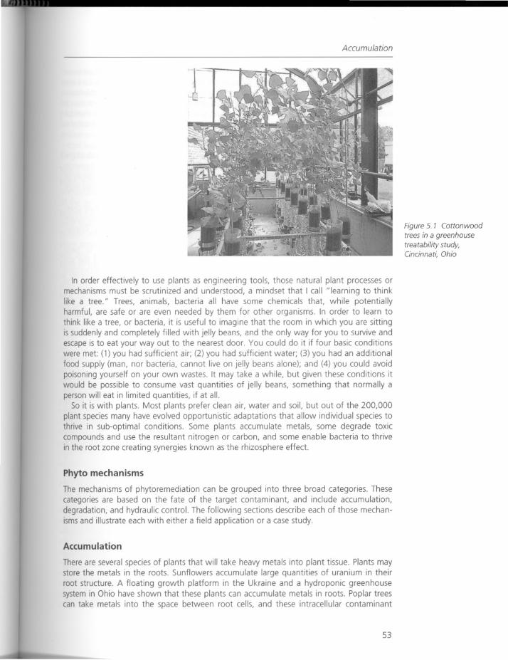
There are several species of plants that will take heavy metals into plant tissue. Plants maystore the metals in the roots. Sunflowers accumulate large quantities of uranium in theirroot structure. A floating growth platform in the Ukraine and a hydroponic greenhousesystem in Ohio have shown that these plants can accumulate metals in roots. Poplar treescan take metals into the space between root cells, and these intracellular contaminant
53
Figure 5. 7 Cottonwoodtrees in a greenhousetreatability study,Cincinnati, Ohio
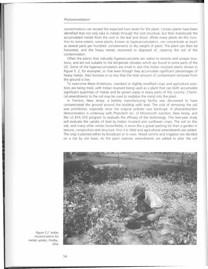
Figure 5.2 Indian
mustard plants formetals uptake, Findlay,
Ohio
Phytoremediation
concentrations can exceed the expected toxic levels for the plant. Certain plants have beenidentified that not only take in metals through the root structure, but then translocate theaccumulated metals from the root to the leaf and shoot. While many plants do this function to some extent, some plants, known as hyperaccumulators, can concentrate as muchas several parts per hundred, contaminants to dry weight of plant. The plant can then beharvested, and the heavy metals recovered or disposed of, cleaning the soil of thecontamination.
Often the plants that naturally hyperaccumulate are native to remote and unique locations, and are not suitable to the temperate climates which are found in some parts of theUS. Some of the hyperaccumulators are small in size (the Indian mustard plants shown inFigure 5. 2, for example), so that even though they accumulate significant percentages ofheavy metals, their biomass in so low that the total amount of contaminant removed fromthe ground is low.
To overcome these limitations, standard or slightly modified crops and agriculture practices are being tried, with Indian mustard being used as a plant that can both accumulatesignificant quantities of metals and be grown easily in many parts of this country. Chemical amendments to the soil may be used to mobilize the metal into the plant.
In Trenton, New Jersey, a battery manufacturing facility was discovered to havecontaminated the ground around the building with lead. The cost of removing the soilwas prohibitive, especially since the original polluter was bankrupt. A phytoextractiondemonstration is underway with Phytotech Inc. of Monmouth Junction, New Jersey, andthe US EPA SITEprogram to evaluate the efficacy of the technology. This two-year studywill evaluate the uptake of lead by Indian mustard and sunflower crops. The soil on thissite, and many other similar brownfields, is more like a gravel parking lot than a garden intexture, composition and structure. First it is tilled and agricultural amendments are added.The crop is planted either by broadcast or in rows. Weed control and irrigation are decidedon a site by site basis. As the plant matures amendments are added to alter the soil
54
Accumulation
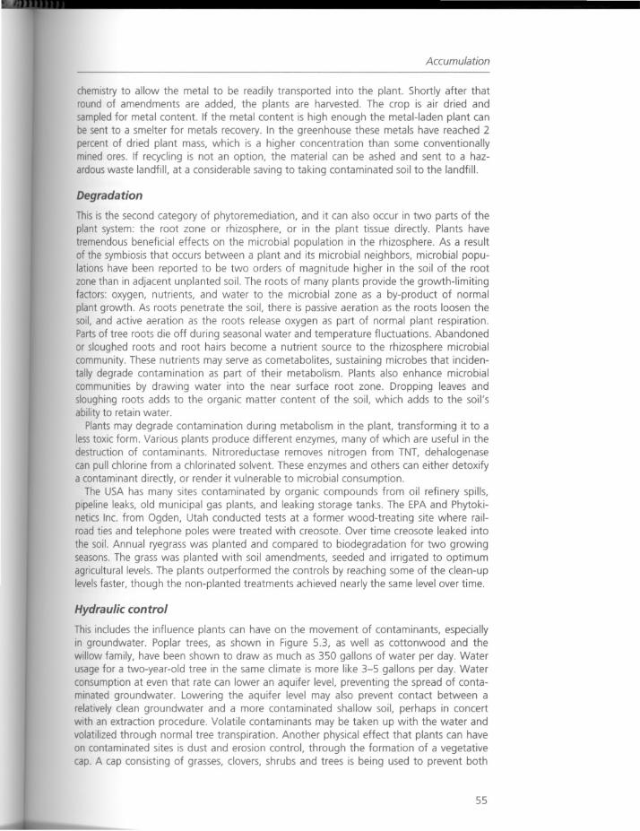
chemistry to allow the metal to be readily transported into the plant. Shortly after thatround of amendments are added, the plants are harvested. The crop is air dried andsampled for metal content. If the metal content is high enough the metal-laden plant canbe sent to a smelter for metals recovery. In the greenhouse these metals have reached 2percent of dried plant mass, which is a higher concentration than some conventionallymined ores. If recycling is not an option, the material can be ashed and sent to a hazardous waste landfill, at a considerable saving to taking contaminated soil to the landfill.
Degradation
This is the second category of phytoremediation, and it can also occur in two parts of theplant system: the root zone or rhizosphere, or in the plant tissue directly. Plants havetremendous beneficial effects on the microbial population in the rhizosphere. As a resultof the symbiosis that occurs between a plant and its microbial neighbors, microbial populations have been reported to be two orders of magnitude higher in the soil of the rootzone than in adjacent unplanted soil. The roots of many plants provide the growth-limitingfactors: oxygen, nutrients, and water to the microbial zone as a by-product of normalplant growth. As roots penetrate the soil, there is passive aeration as the roots loosen thesoil, and active aeration as the roots release oxygen as part of normal plant respiration.Partsof tree roots die off during seasonal water and temperature fluctuations. Abandonedor sloughed roots and root hairs become a nutrient source to the rhizosphere microbialcommunity. These nutrients may serve as cometabolites, sustaining microbes that incidentally degrade contamination as part of their metabolism. Plants also enhance microbialcommunities by drawing water into the near surface root zone. Dropping leaves andsloughing roots adds to the organic matter content of the soil, which adds to the soil'sability to retain water.
Plants may degrade contamination during metabolism in the plant, transforming it to alesstoxic form. Various plants produce different enzymes, many of which are useful in thedestruction of contaminants. Nitroreductase removes nitrogen from TNT, dehalogenasecan pull chlorine from a chlorinated solvent. These enzymes and others can either detoxifya contaminant directly, or render it vulnerable to microbial consumption.
The USA has many sites contaminated by organic compounds from oil refinery spills,pipeline leaks, old municipal gas plants, and leaking storage tanks. The EPA and Phytokinetics Inc. from Ogden, Utah conducted tests at a former wood-treating site where railroad ties and telephone poles were treated with creosote. Over time creosote leaked intothe soil. Annual ryegrass was planted and compared to biodegradation for two growingseasons.The grass was planted with soil amendments, seeded and irrigated to optimumagricultural levels. The plants outperformed the controls by reaching some of the clean-uplevelsfaster, though the non-planted treatments achieved nearly the same level over time.
Hydraulic control
This includes the influence plants can have on the movement of contaminants, especiallyin groundwater. Poplar trees, as shown in Figure 5.3, as well as cottonwood and thewillow family, have been shown to draw as much as 350 gallons of water per day. Waterusage for a two-year-old tree in the same climate is more like 3-5 gallons per day. Waterconsumption at even that rate can lower an aquifer level, preventing the spread of contaminated groundwater. Lowering the aquifer level may also prevent contact between arelatively clean groundwater and a more contaminated shallow soil, perhaps in concertwith an extraction procedure. Volatile contaminants may be taken up with the water andvolatilized through normal tree transpiration. Another physical effect that plants can haveon contaminated sites is dust and erosion control, through the formation of a vegetativecap. A cap consisting of grasses, clovers, shrubs and trees is being used to prevent both
55
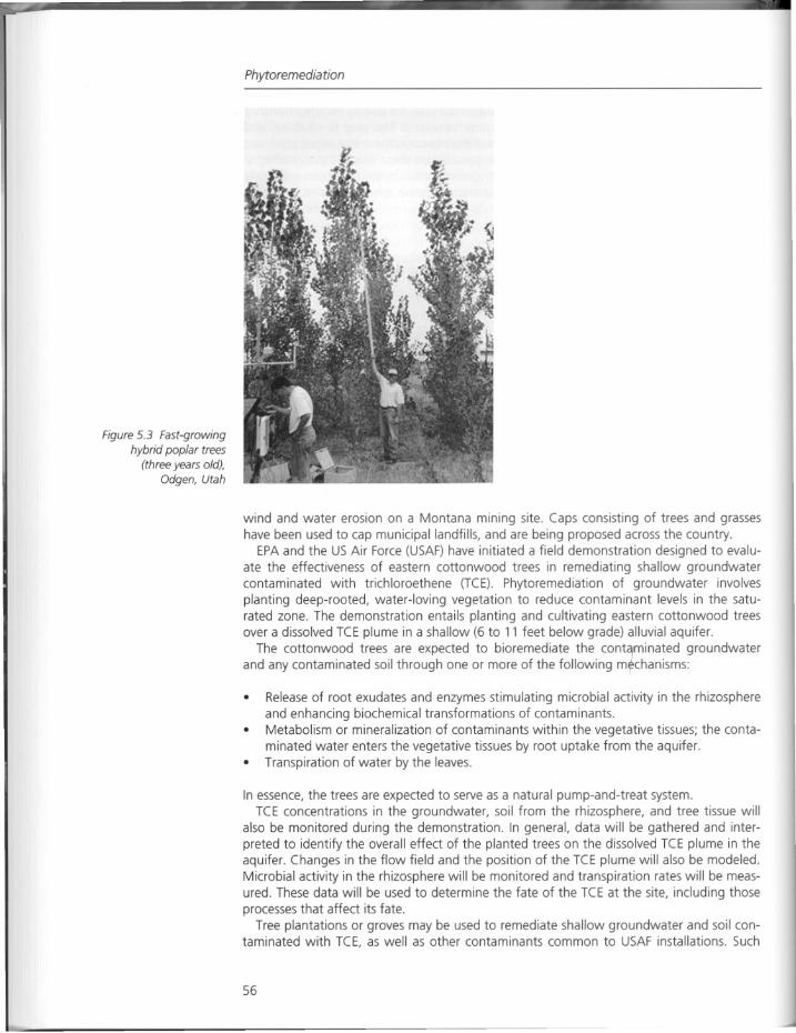
Figure 5.3 Fast-growinghybrid poplar trees
(three years old),Odgen, Utah
Phytoremediation
wind and water erosion on a Montana mining site. Caps consisting of trees and grasseshave been used to cap municipal landfills, and are being proposed across the country.
EPA and the US Air Force (USAF) have initiated a field demonstration designed to evaluate the effectiveness of eastern cottonwood trees in remediating shallow groundwatercontaminated with trichloroethene (TCE). Phytoremediation of groundwater involvesplanting deep-rooted, water-loving vegetation to reduce contaminant levels in the saturated zone. The demonstration entails planting and cultivating eastern cottonwood treesover a dissolved TCE plume in a shallow (6 to 11 feet below grade) alluvial aquifer.
The cottonwood trees are expected to bioremediate the conta,minated groundwaterand any contaminated soil through one or more of the following m~chanisms:
• Release of root exudates and enzymes stimulating microbial activity in the rhizosphereand enhancing biochemical transformations of contaminants.
• Metabolism or mineralization of contaminants within the vegetative tissues; the contaminated water enters the vegetative tissues by root uptake from the aquifer.
• Transpiration of water by the leaves.
In essence, the trees are expected to serve as a natural pump-and-treat system.TCE concentrations in the groundwater, soil from the rhizosphere, and tree tissue will
also be monitored during the demonstration. In general, data will be gathered and interpreted to identify the overall effect of the planted trees on the dissolved TCE plume in theaquifer. Changes in the flow field and the position of the TCE plume will also be modeled.Microbial activity in the rhizosphere will be monitored and transpiration rates will be measured. These data will be used to determine the fate of the TeE at the site, including thoseprocesses that affect its fate.
Tree plantations or groves may be used to remediate shallow groundwater and soil contaminated with TCE, as well as other contaminants common to USAF installations. Such
56
Accumulation
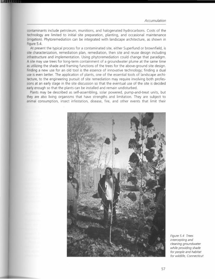
contaminants include petroleum, munitions, and halogenated hydrocarbons. Costs of thetechnology are limited to initial site preparation, planting, and occasional maintenance(irrigation). Phytoremediation can be integrated with landscape architecture, as shown inFigure 5.4.
At present the typical process for a contaminated site, either Superfund or brownfield, issite characterization, remediation plan, remediation, then site and reuse design includinginfrastructure and implementation. Using phytoremediation could change that paradigm.A site may use trees for long-term containment of a groundwater plume at the same timeas utilizing the shade and framing functions of the trees for the above-ground site design.Finding a new use for an old tool is the essence of innovative technology; finding a dualuse is even better. The application of plants, one of the essential tools of landscape architecture, to the engineering pursuit of site remediation may require involving both professions at an early stage in the site discussion so that the eventual use of the site is decidedearly enough so that the plants can be installed and remain undisturbed.
Plants may be described as self-assembling, solar powered, pump-and-treat units, butthey are also living organisms that have strengths and limitation. They are subject toanimal consumption, insect infestation, disease, fire, and other events that limit their
57
Figure 5.4 Trees
intercepting andcleaning groundwaterwhile providing shadefor people and habitatfor wildlife, Connecticut
Phytoremediation
effectiveness. They also change their work during non-daylight hours, and shut downentirely during certain times of the year. On the positive side they are sometimes selfrepairing, and seem to encourage less human vandalism than mechanical systems. A greatdeal of research remains before the mechanisms of phytoremediation are sufficientlyunderstood for widespread application of the various technologies.
For a remediation engineer plants may seem less reliable and predictable than physical,mechanical, or chemical systems. For the landscape architect, trying to incorporate remediation goals in a planting plan may be frustrating through limits to planting palette and theplacement of vegetation. For the public, as long as the health risk is equally averted by allremediation options, phytoremediation enjoys a certain intuitive support. Green growingsites feel environmentally benign. For the ecosystem, planting a site can be a first step tohabitat creation, soil enhancement, erosion control, and other benefits, alongsidecontaminant reduction and progressive design.
58
Response
Response
Recovery with plants
The healing properties of plants have been understood over the ages. From the ancientmedicinal use of herbs and roots to the current use of urban canopy street trees to filterdust and absorb air pollutants, plants have been selectively used as tools to promoteenvironmental and human health.
"Finding a new use for an old tool is the essence of innovative technology; finding adual use is even better." Rock's statement in his introduction to the science, technologyand application of phytoremediation illustrates his experience of integrating technologyand site design through the application of plants, or more correctly introduced plantingsystemson manufactured sites.
Some of the broader issues currently facing manufactured sites include treating thesocial malaise that accompanies these sites to create livable neighborhoods, the development of environmental education about urban reclamation and manufactured sites, andassistance in advancing trends in technology, particularly regarding innovations in siteassessmentand remediation.
The use of phytoremediation as an innovative method of clean-up, as outlined by Rock,directly addresses a number of these issues - from the ability to connect planting systemsused for clean-up, to larger site open space and vegetation strategies, to the use of phytotechnologies within community greening programs for inner-city environments.
There are two issues related to the use of phyto-technologies with site design and planning strategies that are significant for future interdisciplinary work between engineers anddesigners. These are: (1) the differing concerns of time between remediation and development practices; (2) what may be termed the difference in mindsets between phytoengineers and site designers regarding the forms of planted systems and their ongoingperformance, operation and predictability. In short, the expectations for the duration andsite application of phytoremediation
Time
A phytoremediation system can be thought of as part of the delivery of a usable site andconstruction program in one of two ways. First, over the long term (say thirty years),where phytoremediation is "embedded" in evolving interim and temporary land-use andsite programs, or second, where anticipated development is in an accelerated time-frameof nine months to three years. Here phytoremediation systems are implemented as part ofthe delivery of a usable site and construction program.
Application
Phytoremediation plants perform in different ways and are viewed in a quite different lightfrom the standard conventions of horticultural and landscape design. In reviewing theliterature of phytoremediation, one is struck by the insistence in the scientific and industryresearch papers on viewing the planted systems as derived from an agricultural scale ofapplication (the use of terms such as "crop," "fields," "harvest" and "hedgerows").
There are a number of issues that still have to be addressed before remediation and site
design can be truly integrated. Receiving attention from industry researchers and regulatory agencies, such as the US.EPA National Risk Management Laboratory in Cincinnattiwhere Rock is based, are such topics as plant selection and matching to contaminant type,
59

Phytoremediation
the use of native plants and habitat restoration in phytoremediation, the evaluation ofclaims, and the continued exploration of plant and contaminant mechanisms.
Phytoremediation is at a point in its evolution where the nature, scale, complexity andlocation of manufactured sites can start to shape the application possibilities for smallerurban sites. Among these are the existing urban site conditions of ground and water, theplant growth concerns on these sites from microclimate and poor soils, and the concernsof adjacent communities and stakeholders.
60
Chapter 6
Engineering urban brownfielddevelopment:examples from Pittsburgh
Sue McNeil and Deborah Lange
Brownfields are abandoned, idled or underused industrial or commercial facili
ties where expansion or redevelopment is complicated by real or perceivedenvironmental contamination.
(Brownfields definition, US.EPA 1996)
Introduction
Engineering urban brownfield development has a broader meaning, as the revitalization ofthese sites must address a diverse set of issues. These include community attitudes,environmental issues, the provision of new or the renewal of existing infrastructure, urbanand land use planning, socio-economic issues, historical legacies, financial issues, legal andregulatory environment and political forces. This essay looks at each of these issues andexplores some of the contributions research has made to facilitating this process. Two casestudy sites from Pittsburgh are used to illustrate the concepts presented in this chapter.
Diverse perspectives on brownfield development
The diverse perspectives on brownfield development add complexity to the problem asstakeholders struggle to determine alternatives that are feasible, and ideally, optimal. Thestakeholders include owners; developers, communities, economic development agencies,city, regional, county, and state governments, and regulators.
Community attitude
Communities are critical stakeholders who significantly influence the set of acceptablealternatives or options. Community support can" make or break" a project, but rarely dothe affected parties interact at the early stages of development. The most successfulbrownfield developments have involved a bottom-up effort that involved the communityin seeking alternative site uses and maintaining the momentum in the rather lengthydevelopment process. For example, positive community involvement was instrumental infinding an alternative use for a former munitions factory in Hays, a Pittsburgh community(Barton 1996).
61
Engineering urban brownfield development
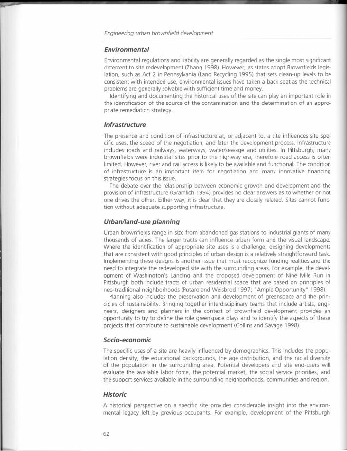
Environmental
Environmental regulations and liability are generally regarded as the single most significantdeterrent to site redevelopment (Zhang 1998). However, as states adopt Brownfields legislation, such as Act 2 in Pennsylvania (Land Recycling 1995) that sets clean-up levels to beconsistent with intended use, environmental issues have taken a back seat as the technical
problems are generally solvable with sufficient time and money.Identifying and documenting the historical uses of the site can play an important role in
the identification of the source of the contamination and the determination of an appropriate remediation strategy.
Infrastructure
The presence and condition of infrastructure at, or adjacent to, a site influences site specific uses, the speed of the negotiation, and later the development process. Infrastructureincludes roads and railways, waterways, water/sewage and utilities. In Pittsburgh, manybrownfields were industrial sites prior to the highway era, therefore road access is oftenlimited. However, river and rail access is likely to be available and functional. The conditionof infrastructure is an important item for negotiation and many innovative financingstrategies focus on this issue.
The debate over the relationship between economic growth and development and theprovision of infrastructure (Gramlich 1994) provides no clear answers as to whether or notone drives the other. Either way, it is clear that they are closely related. Sites cannot function without adequate supporting infrastructure.
Urban/land-use planning
Urban brownfields range in size from abandoned gas stations to industrial giants of manythousands of acres. The larger tracts can influence urban form and the visual landscape.Where the identification of appropriate site uses is a challenge, designing developmentsthat are consistent with good principles of urban design is a relatively straightforward task.Implementing these designs is another issue that must recognize funding realities and theneed to integrate the redeveloped site with the surrounding areas. For example, the development of Washington's Landing and the proposed development of Nine Mile Run inPittsburgh both include tracts of urban residential space that are based on principles ofneo-traditional neighborhoods (Putaro and Weisbrod 1997; "Ample Opportunity" 1998).
Planning also includes the preservation and development of greenspace and the principles of sustainability. Bringing together interdisciplinary teams that include artists, engineers, designers and planners in the context of brownfield development provides anopportunity to try to define the role greenspace plays and to identify the aspects of theseprojects that contribute to sustainable development (Collins and Savage 1998).
Socio-economic
The specific uses of a site are heavily influenced by demographics. This includes the population density, the educational backgrounds, the age distribution, and the racial diversityof the population in the surrounding area. Potential developers and site end-users willevaluate the available labor force, the potential market, the social service priorities, andthe support services available in the surrounding neighborhoods, communities and region.
Historic
A historical perspective on a specific site provides considerable insight into the environmental legacy left by previous occupants. For example, development of the Pittsburgh
62
An interdisciplinary approach to brownfield issues
Technology Center was halted for several years as engineers and scientists were confounded by the presence of ferrous cyanide. Review of the Sanborn maps determined thata manufactured gas plant had occupied the site prior to the steel mill. The cyanide, generated from the purification of manufactured gas, was found to be localized and stable, andthen building was able to proceed (Messenger and Santoro 1996).
History also provides significant insight into the social evolution of a site, its proximity totransportation and neighboring residential areas, and the concept of site criticality as specific sites serve as the focus for a community or a common thread that holds the community together. Although the majority of an industry's employees may not be drawn from theadjacent community, the industrial focus was often the thread that united the community.When the industry leaves, the community loses its hope and vitality.
Financial
The financing of brownfield developments is one of the more complex issues facing thestakeholders. A wide range of sources of money is available. Often particular sources areearmarked for particular activities. For example, clean-up monies can come from a varietyof different sources, infrastructure improvements can be paid for with tax incrementfinancing or make use of state infrastructure banks. Clearly, the most successful developments have been public/private partnerships where many stakeholders have a vested interest in the success of the development.
Legal/regulatory
The legal and regulatory environment (at the state and federal levels) has had a significantimpact on the phenomenon of brownfields. State and federal legislation has allowed forclean-up consistent with intended use, and limited liability of lenders. Questions still existin terms of responsibilities for pre-existing conditions, future discoveries and future regulations. Pennsylvania Acts 1 and 2 provided protection from some of the liability issues andpaved the way for responsible clean-up consistent with the intended use of the site (LandRecycling1995).
Other legal and regulatory issues include compliance with zoning, stormwater drainage,driveway accessand transportation impacts.
Political
Brownfields can represent a significant asset to the communities in which they sit; therefore, political issues can be difficult. The existence of political support for these issuesrelates to the overall economy, the power of urban versus suburban voters and the natureof the area.
An interdisciplinary approach to brownfield issues
The Brownfields Center (TBC), a joint venture of the Carnegie Mellon University and theUniversity of Pittsburgh, focuses on research, education and outreach, and as such itservesas a link between academia and the communities.
Faculty, staff and students participating in this interdisciplinary center come from variedbackgrounds including art, architecture, economics, decision sciences, civil and environmental engineering, history, urban planning, economic development and public policy.TBC has also developed links to the STUDIO for Creative Inquiry, and the Center for Economic Development at Carnegie Mellon. TBC also has extensive interactions with federal,state and local government agencies such as Pennsylvania Department of Transportation
63
Engineering urban brownfield development
(PennDOT), Southwestern Pennsylvania Regional Planning Commission (SPRPC), UrbanRedevelopment Authority (URA), City Planning, Pennsylvania Department of EnvironmentalProtection (PaDEP), Environmental Protection Agency (EPA), Housing and Urban Development (HUD), Department of Energy (DOE) and private sector firms such as consultants,banks and developers.
TBC's activities include maintenance of an extensive website with case studies, other
brownfield links and reports (http://www.ce.cmu.edu/Brownfieldsl), participation in conferences as program chairs, session organizers, presenters and exhibitors, and presentationof brownfield issues to diverse audiences. TBC is also actively involved in the training ofthe workforce through the education of both graduate and undergraduate students whoparticipate in the projects and activities.
The interest in abandoned industrial site redevelopment, and the close ties betweenurban revitalization and infrastructure renewal, motivated the formation of TBC. These
concepts form the foundation for a National Science Foundation (NSF) funded projecttitled "Brownfield Development: The Implications for Urban Infrastructure." This projectbuilds on research and development related to civil infrastructure systems. It also leveragesCarnegie Mellon's location in a city with abundant brownfields and in a state with legislation to encourage brownfield development.
The objective of the NSF project is to develop a rational, consistent and systematicapproach to decision-making related to infrastructure renewal through:
• development and transfer of computer-based decision-making tools;• exploration of the role of computer-based collaborative environments;• collection of, access to, and management of relevant data;• analysis of qualitative and quantitative information, site and infrastructure assessments
and development of rational decision-making strategies;• recognition of the historical process and context of industrial site development and
redevelopment;• exploration of financing opportunities.
The project has involved information gathering, exploration of existing tools, tool andmodel development, system integration and documentation, and technology transfer.Specific components of the project include:
• understanding the brownfield development process through case studies;• exploration of impact assessment tools;• enhancement of traffic and transportation models;• integration of condition assessment and decision-making methodology;• exploration of life cycle cost analysis.
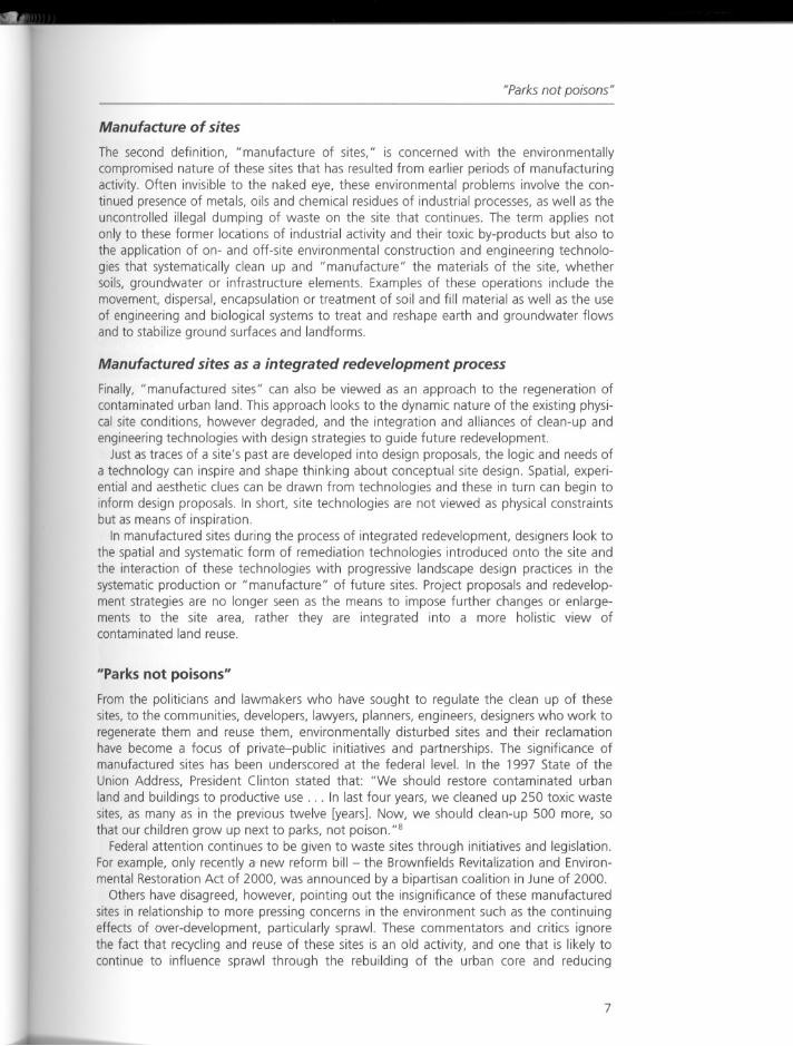
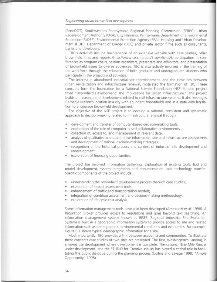
Some information management tools have also been developed (Amekudzi et at. 1998). ARegulation Broker provides access to regulations and goes beyond text searching. Aninformation management system known as RISES (Regional Industrial Site EvaluationSystem) is built in a geographic information system to provide access to site and relatedinformation such as demographics, environmental conditions and economics. For example,Figure 6.1 shows typical demographic information for a site.
Most importantly, TBC provides a link between academia and communities. To illustratethese concepts case studies of two sites are presented. The first, Washington's Landing, isa mixed use development where development is complete. The second, Nine Mile Run, isunder development, and the STUDIO for Creative Inquiry has played a critical role in facilitating the public dialogue during the planning process (Collins and Savage 1998; "AmpleOpportunity" 1998).
64
Within a,clfi r.dius::
ToLiI pettOn! In (his Irea is lIW480.TOhl Households is 128]32.
The Average Median HH Income S 21811(this is 18.4" ofth. Allegheny County average).M.I. unemployment ~te is 11 "-Female umempfoyment late is 82 "
The to~1 working population or the area is 202502 of which
21 •. hIVe • bamelal'S degree or higher level of eduution .
./
Travel Time to Work •1990
Nine Mile Run
Figure 6.1Demographic module inRISES:typicalinformation
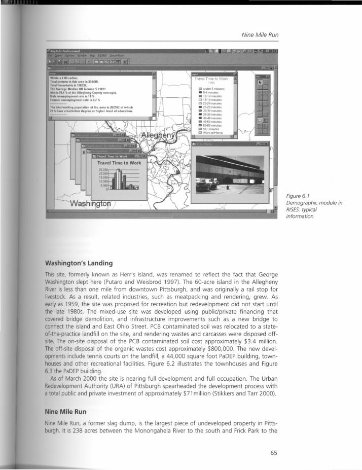
Washington's landing
This site, formerly known as Herr's Island, was renamed to reflect the fact that GeorgeWashington slept here (Putaro and Weisbrod 1997). The 60-acre island in the AlleghenyRiver is less than one mile from downtown Pittsburgh, and was originally a rail stop forlivestock. As a result, related industries, such as meatpacking and rendering, grew. Asearly as 1959, the site was proposed for recreation but redevelopment did not start untilthe late 1980s. The mixed-use site was developed using public/private financing thatcovered bridge demolition, and infrastructure improvements such as a new bridge toconnect the island and East Ohio Street. PCB contaminated soil was relocated to a state
of-the-practice landfill on the site, and rendering wastes and carcasses were disposed offsite. The on-site disposal of the PCB contaminated soil cost approximately $3.4 million.The off-site disposal of the organic wastes cost approximately $800,000. The new developments include tennis courts on the landfill, a 44,000 square foot PaDEPbuilding, townhouses and other recreational facilities. Figure 6.2 illustrates the townhouses and Figure6.3 the PaDEPbuilding.
As of March 2000 the site is nearing full development and full occupation. The UrbanRedevelopment Authority (URA) of Pittsburgh spearheaded the development process witha total public and private investment of approximately $71 million (Stikkers and Tarr 2000).
Nine Mile Run
Nine Mile Run, a former slag dump, is the largest piece of undeveloped property in Pittsburgh. It is 238 acres between the Monongahela River to the south and Frick Park to the
65
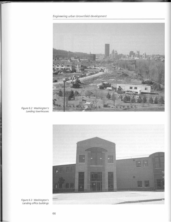
Figure 6.2 Washington's
Landing townhouses
Figure 6.3 Washington'sLanding office buildings
Engineering urban brownfield development
66
Acknowledgements
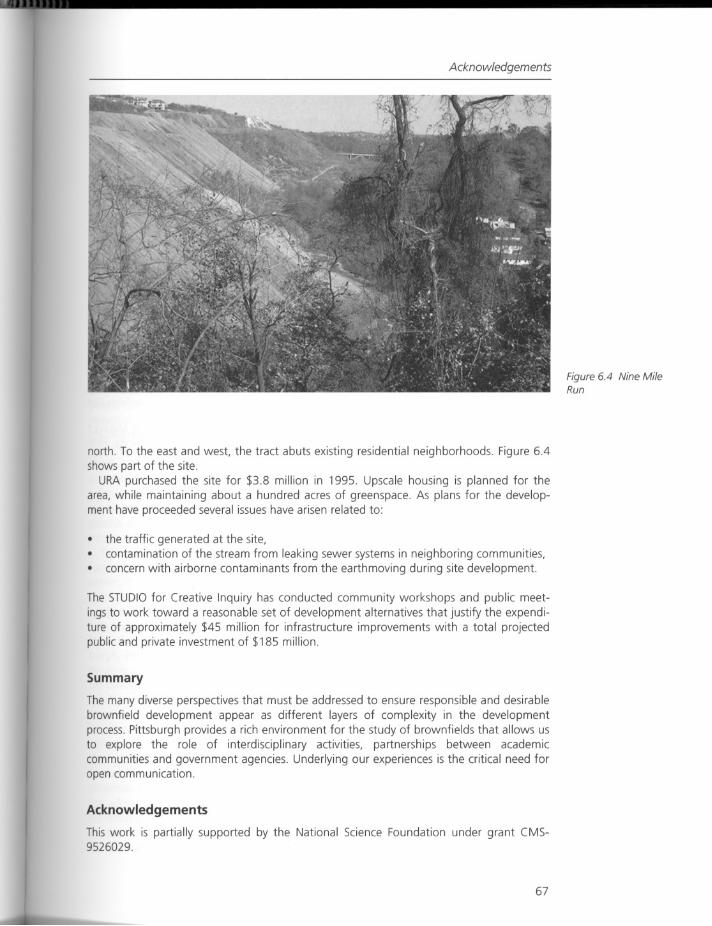
north. To the east and west, the tract abuts existing residential neighborhoods. Figure 6.4shows part of the site.
URA purchased the site for $3.8 million in 1995. Upscale housing is planned for thearea, while maintaining about a hundred acres of greenspace. As plans for the development have proceeded several issues have arisen related to:
• the traffic generated at the site,contamination of the stream from leaking sewer systems in neighboring communities,concern with airborne contaminants from the earthmoving during site development.
The STUDIO for Creative Inquiry has conducted community workshops and public meetings to work toward a reasonable set of development alternatives that justify the expenditure of approximately $45 million for infrastructure improvements with a total projectedpublic and private investment of $185 million.
Summary
The many diverse perspectives that must be addressed to ensure responsible and desirablebrownfield development appear as different layers of complexity in the developmentprocess. Pittsburgh provides a rich environment for the study of brownfields that allows usto explore the role of interdisciplinary activities, partnerships between academiccommunities and government agencies. Underlying our experiences is the critical need foropen communication.
Acknowledgements
This work is partially supported by the National Science Foundation under grant CMS9526029.
67
Figure 6.4 Nine MileRun
Engineering urban brownfield development
References
Amekudzi, Adjo, Paul Fischbeck, James Garrett, Jr, Haris Koutsopoulos, Sue McNeil and Mitchell Small(1998) "Computer Tools to Facilitate Brownfield Development," Public Works Management andPolicy 2 (3) (January).
"Ample Opportunity: A Community Dialogue" (1998) Final Report, Nine Mile Run Greenway Project,Studio for Creative Inquiry, Carnegie Mellon University, Pittsburgh, Pa. (February).
Barton, J.P. (1996) "Hays" Project Report, Department of Civil and Environmental Engineering,Carnegie Mellon University, Pittsburgh, Pa. (http://www.ce.cmu.edu/BrownfieldsiNSF/sitesihaysl)
Collins, Tim and Kirk Savage (1998) "Brownfields as Places," Public Works Management and Policy 2(3) (January).
Gramlich, Edward (1994) "Infrastructure Investment: A Review Essay," Journal of Economic Literature,vol. XXXII (September).
Land Recycling and Environmental Remediation Act 2, The General Assembly of Pennsylvania, SenateBill NO.1 Session of 1995 (http://www./ibertynet.org:80/-pahousellaws95/95act002.html)
Messenger, Adrienne and Carla Santoro (1996) "Pittsburgh Technology Center," Project Report,Department of Civil and Environmental Engineering, Carnegie Mellon University, Pittsburgh, Pa.(http://www .ce.cm u.edu/B rownfieldsiN SF/siteslptcl)
Putaro, Sarah and Kathryn Weisbrod (1997) "Washington's Landing," Project Report, TheBrownfields Center, Carnegie Mellon University, Pittsburgh, Pa.(http://www.ce.cmu.edulBrownfieldsiNSF/siteslWashlandlindex.htm)
Stikkers, David E. and Joel A. Tarr (2000) "Pittsburgh's Brownfields: Case Studies in Redevelopment,"Working Paper, The Brownfields Center, Carnegie Mellon University, Pittsburgh, Pa. (March).
United States Environmental Protection Agency, Region 5 Office of Public Affairs, Brownfields FactSheet, 1996.
Zhang, Jianyu (1998) "Concerns and Priorities of Stakeholders in Brownfields Decision Making,"Working Paper, Department of Engineering and Public Policy, Carnegie Mellon University, Pittsburgh, Pa.
68
Response
Response
Living laboratories: studies in infrastructure andindustrial land
Since most American industrial facilities of the eighteenth and nineteenth centuries werelocated in urban centers, the primary sources for what are now known as "manufacturedsites" or brownfields are located in or near our metropolitan centers. The location anddiversity of interests woven into these sites and the complex treatments required for cleanup necessitate that strong links be developed between urban design, science, economics,legal, community and public process to develop strategies for successful remediation. Bothof the case studies - Washington's Landing and Nine Mile Run - offer tangible examplesof how several of these and other issues have been addressed through practice.
As a model for data gathering, information dissemination, and project documentationThe Brownfields Center (TBC) at Carnegie Mellon University offers a unique framework tolink the interdisciplinary work of academic teams to the concerns of local communities,federal, state and local agencies, private consultants and industry. This alliance suggests agreater function for academics through their traditional role as data collectors, coordinators, researchers and policy advocates, and their institutions can serve as data resourcebanks, disseminating timely research results and post-construction evaluations of recentremediation projects.
Universities are experienced in working across disciplines and academics can bring theirexpertise in mediation and community facilitation to the process of brownfield development. TBC offers a practical model integrating the new technologies (the web) with traditional research (case studies) to inform and link diverse participants together and providesa forum in which brownfield issues are discussed and the latest innovations in technologyare presented. In addition, web-based accessibility offers a public forum through whichdebate and discussion take place and both experts and novices can decimate and acquireinformation.
This model also suggests a framework in which to develop future academic curricula
focusin~ on brownfields, and other forms of environmental remediation. As a visionarycenter, it offers a practical real world model of interdisciplinary collaboration among students in design, science, law, government and public policy. How might this model beapplied at other institutions?
In the model developed by TBC over the past three years the focus has been on urbanbrownfield remediation. It is not clear if this interest is the result of their location in Pitts
burgh, Pennsylvania, a city with abundant brownfield sites, or if it is tied to the vigoroushousing and commercial climate in which alternative urban sites are now being consideredfor development. It may also be because of public policy revisions to change the scope ofliability carried by developers and establishing more realistic standards and time-frames forclean-up. Concurrently, and not being directly addressed by the TBC, there is a growingtrend to remediate sites outside of urban boundaries. These include abandoned strip or pitmines, landfills, riparian corridors and hazardous storage or manufacturing facilities. Whilethe location of these sites may be rural, the diverse range of issues, including varied stakeholders, socio-economic implications, financial and regulatory complexities, are notdissimilar from those found in the urban context. TBCs model may offer some strategiesfor addressing similar issues at rural sites. While the political structure and nature ofcommunity concerns may differ, many of the technical issues and similar team/partnershipmodels may be applied when addressing rural site problems, including water quality, soilcontamination, riparian restoration, landfill closures and innovative "green" stormwater
69
Engineering urban brownfield development
treatment systems. As the type of sites requiring remediation continue to expand, itbecomes clear that a model similar to that developed by McNeil and Lange may be equallyvaluable for these projects.
As McNeil and Lange have pointed out, it is critical to understand the history of the sitein order to evaluate the patterns and degree of contamination, since the past historic usesand patterns of contamination have a direct correlation to the design solution. The distribution and selection of uses are in direct response to the levels of contamination and thedegree to which the various areas within the site can be cleaned. As is pointed out inChapter 7 by Dr Dante Tedaldi in the "Tacoma Asarco Smelter Site," the distribution ofland uses as shown in the master plan was based on developing uses compatible with thelevel of clean-up that could be reasonably achieved. In areas that could be substantiallycleaned, housing, commercial and office uses were planned. For those where substantialclean-up could not be achieved, a large park was designed with a containment systeminstalled below and a capping system above.
What would be equally interesting, and maybe achievable through the case studiesbeing compiled by TBC, is to see if there are discrepancies between the chosen uses andthe level of clean-up achieved per differing communities. In other words are somecommunities held hostage by past land uses, are differing standards being applied, and ispolitical leverage influencing allowable types of uses and the integrity of the design resolutions?
Since brownfields are defined by their current condition, the sites often vary dramatically in scale. Are some sites too small for development and better suited as laboratoriesfor exploration of alternative remediation methods, as was suggested in Chapter 4 by EricCarman in "From Laboratory to Landscape"? An example was presented where it was noteconomically feasible to develop most decommissioned gas stations. In Chapter 3, theessay "Beyond Clean-up of Manufactured Sites: Remediation, Restoration and Renewal ofHabitat" by Dr Lucinda Jackson, a value was found in which the sites were considered laboratories for experimentation and data collection. On the larger scale many of these largeparcels or linked parcels offer an opportunity for urban renewal and are candidates forintegrated open spaces that can be linked to existing open space systems and seen asanchors for economic revitalization. Another strategy to address is smaller peripheral sitesthat might link prime development sites in the downtown core with contaminated sites inoutlying residential areas. Through various incentives and public support a developer couldredevelop a downtown site for maximum profit if they agree to take on an outlying sitefor conversion into housing or residential uses. Remediation should not be a limitation togood urban design.
McNeil and Lange also raise the issue of sustainability. We must be careful in a zest toremediate these sites not to trade in one problem for another. Despite what may beincreased costs are we recreating productive landscapes, or are we treating contaminantson-site so that we don't create additional hot spots off-site? Are we using design to createcommunity amenities that re-establish community in a sustainable manner? The challengewe're facing as we move into the twenty-first century is not only to remediate contamination, but to create thoughtfully designed healthy communities that overcome the environmental ravages of our history.
While the diverse perspectives common to these projects, including those of thecommunity, the developer, the politician and banker suggest a complex process, they alsooffer tremendous opportunities. The inclusionary process proposed in this chapter requiresconsiderable time investment over a long period; however, when successful, it offers adiverse set of potential solutions and innovative strategies, ideas that may not surface in amore constrictive process. Given the great diversity of the stakeholders and varying levelsof expertise among the participants, what other models can be borrowed or created todevelop clear design criteria, evaluate options, and to maximize economic, environmental
70

Response
and social opportunities? How does a manufactured site model such as that used by PeterLatz (Chapter 2), with a strong focus on community participation and stewardship,compare with models currently being used in the United States? How does the culture anddiffering political systems found in other countries influence the process? Given theimportance of a bottom-up effort with the community why are there still so many projectsthat lack a front-end outreach component? Clearly the skill level of each communityorganization will vary depending on their political status, experience with outreachprocessesand internal cohesiveness. Understanding the abilities of each unique community early in the process will be critical in any bottom-up, inclusive planning. What are someof the best methods to inform the community and solicit their participation without alarming them and beginning the process with suspicion and distrust? What tools can be usedto understand the dynamics of the community if in fact it is not organized or clearly identifiable? Who will speak for the community? Should there be multiple voices or is it feasibleto develop consensus despite the fact that expectations among the community may varywidely? As the number of case studies compiled increases and methodologies of practiceemerge, perhaps some of these questions will be addressed.
The authors also raise several questions, two of which have significant application forfuture researchers. Are there other successful interdisciplinary models, linking the publicwith governmental agencies, academic institutes or departments, and private developmentcorporations, that may offer alternate approaches applicable to brownfield remediation?The second question is how can a balance be struck between an open exchange ofinformation, a timely decision-making process, economic feasibility and inclusionaryprocessesso they can operate as complementary components?
71
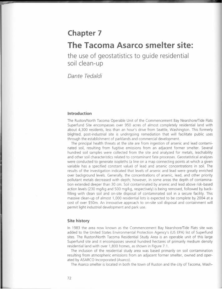
Chapter 7
The Tacoma Asarco smelter site:
the use of geostatistics to guide residentialsoil clean-up
Dante Tedaldi
Introduction
The Ruston/North Tacoma Operable Unit of the Commencement Bay NearshorelTide FlatsSuperfund Site encompasses over 950 acres of almost completely residential land withabout 4,300 residents, less than an hour's drive from Seattle, Washington. This formerlyblighted, post-industrial site is und~rgoing remediation that will facilitate public usesthrough the establishment of parklands and commercial development.
The principal health threats at the site are from ingestion of arsenic and lead contaminated soil, resulting from fugitive emissions from an adjacent former smelter. Severalhundred soil samples were collected from the site and analyzed for metals, leachabilityand other soil characteristics related to contaminant fate processes. Geostatistical analyseswere conducted to generate isopleths (a line on a map connecting points at which a givenvariable has a specified constant value) of lead and arsenic concentrations in soil. Theresults of the investigation indicated that levels of arsenic and lead were greatly enrichedover background levels. Generally, the concentrations of arsenic, lead, and other prioritypollutant metals decreased with depth; however, in some areas the depth of contamination extended deeper than 30 em. Soil contaminated by arsenic and lead above risk-basedaction levels (230 mg/kg and 500 mg/kg, respectively) is being removed, followed by backfilling with clean soil and on-site disposal of contaminated soil in a secure facility. Thismassive clean-up of almost 1,000 residential lots is expected to be complete by 2004 at acost of over $50m. An innovative approach to on-site soil disposal and containment willpermit light industrial development and park use.
Site history
In 1983 the area now known as the Commencement Bay NearshorelTide Flats site wasadded to the United States Environmental Protection Agency's (US EPA) list of Superfundsites. The Ruston/North Tacoma Residential Study Area is an operable unit of this largeSuperfund site and it encompasses several hundred hectares of primarily medium densityresidential land with over 1,800 homes, as shown in Figure 7.1.
The inclusion of the residential study area was based primarily on soil contaminationresulting from atmospheric emissions from an adjacent former smelter, owned and operated by ASARCO Incorporated (Asarco).
The Asarco smelter is located in both the town of Ruston and the city of Tacoma, Wash-
72
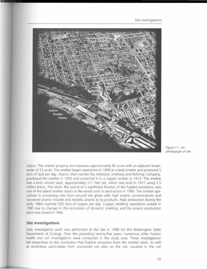
Site investigations
ington. The smelter property encompasses approximately 80 acres with an adjacent breakwater of 23 acres. The smelter began operations in 1890 as a lead smelter and produced 5tons of lead per day. Asarco, then named the American Smelting and Refining Company,purchased the smelter in 1905 and converted it to a copper smelter in 1912. The smelterhad a brick smoke stack, approximately 571 feet tall, which was built in 1917 using 2.5million bricks. This stack, the source of a significant fraction of the fugitive emissions, wasone of the tallest smelter stacks in the world until its destruction in 1993. The smelter specialized in processing ores from around the globe with high arsenic concentrations andrecovered arsenic trioxide and metallic arsenic as by-products. Peak production during theearly 1980s reached 500 tons of copper per day. Copper smelting operations ceased in1985 due to changes in the economics of domestic smelting, and the arsenic productionplant was closed in 1986.
Site investigations
Early investigatory work was performed at the site in 1988 for the Washington StateDepartment of Ecology. Over the preceding twenty-five years, numerous other humanhealth and soil investigations were conducted in the study area. These investigationsled researchers to the conclusion that fugitive emissions from the smelter stack, as wellas wind-blow particulates from uncovered are piles on the site, resulted in the soil
73
Figure 7. 7 Air
photograph of site
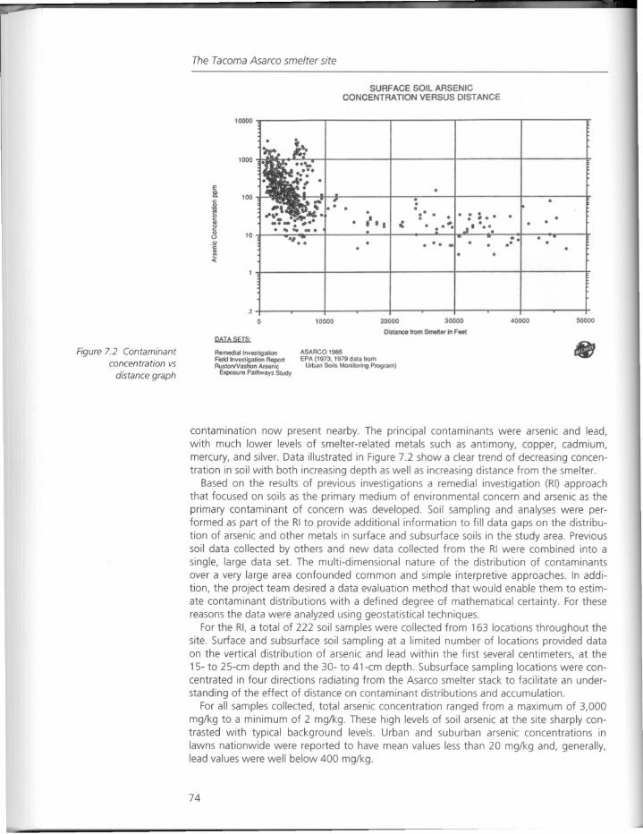
The Tacoma Asarco smelter site
SURFACE SOil ARSENICCONCENTRATION VERSUS DISTANCE
10000
1000
E
8: 100~ ~~a 100 0j<
.• " I •
···:-. . ...•..
.... - ...
.1
o 10000 20000 30000
Distance from Smelter in Feot
40000 50000
Figure 7.2 Contaminantconcentration vs
distance graph
Remedial InvestigationFoeldInvesHgation ReponRustorVVashon Arsenic
Exposu,e Pa,hways S'udy
ASARCO 1985EPA (1973.1979 data f,om
Urban Soils Moniloring Program)
contamination now present nearby. The principal contaminants were arsenic and lead,with much lower levels of smelter-related metals such as antimony, copper, cadmium,mercury, and silver. Data illustrated in Figure 7.2 show a clear trend of decreasing concentration in soil with both increasing depth as well as increasing distance from the smelter.
Based on the results of previous investigations a remedial investigation (RI) approachthat focused on soils as the primary medium of environmental concern and arsenic as theprimary contaminant of concern was developed. Soil sampling and analyses were performed as part of the RI to provide additional information to fill data gaps on the distribution of arsenic and other metals in surface and subsurface soils in the study area. Previoussoil data collected by others and new data collected from the RI were combined into asingle, large data set. The multi-dimensional nature of the distribution of contaminantsover a very large area confounded common and simple interpretive approaches. In addition, the project team desired a data evaluation method that would enable them to estimate contaminant distributions with a defined degree of mathematical certainty. For thesereasons the data were analyzed using geostatistical techniques.
For the RI, a total of 222 soil samples were collected from 163 locations throughout thesite. Surface and subsurface soil sampling at a limited number of locations provided dataon the vertical distribution of arsenic and lead within the first several centimeters, at the
15- to 25-cm depth and the 30- to 41-cm depth. Subsurface sampling locations were concentrated in four directions radiating from the Asarco smelter stack to facilitate an understanding of the effect of distance on contaminant distributions and accumulation.
For all samples collected, total arsenic concentration ranged from a maximum of 3,000mg/kg to a minimum of 2 mg/kg. These high levels of soil arsenic at the site sharply contrasted with typical background levels. Urban and suburban arsenic concentrations inlawns nationwide were reported to have mean values less than 20 mg/kg and, generally,lead values were well below 400 mg/kg.
74
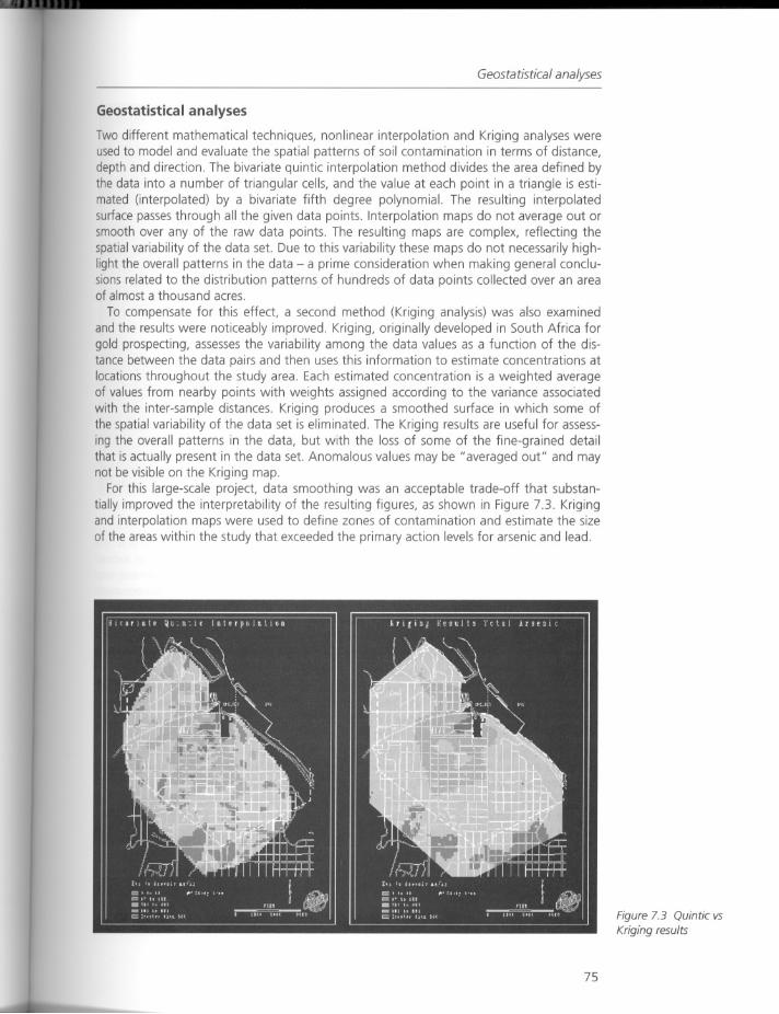
Geostatistical analyses
Geostatistical analyses
Two different mathematical techniques, nonlinear interpolation and Kriging analyses wereusedto model and evaluate the spatial patterns of soil contamination in terms of distance,depth and direction. The bivariate quintic interpolation method divides the area defined bythe data into a number of triangular cells, and the value at each point in a triangle is estimated (interpolated) by a bivariate fifth degree polynomial. The resulting interpolatedsurface passes through all the given data points. Interpolation maps do not average out orsmooth over any of the raw data points. The resulting maps are complex, reflecting thespatial variability of the data set. Due to this variability these maps do not necessarily highlight the overall patterns in the data - a prime consideration when making general conclusions related to the distribution patterns of hundreds of data points collected over an areaof almost a thousand acres.
To compensate for this effect, a second method (Kriging analysis) was also examinedand the results were noticeably improved. Kriging, originally developed in South Africa forgold prospecting, assesses the variability among the data values as a function of the distance between the data pairs and then uses this information to estimate concentrations atlocations throughout the study area. Each estimated concentration is a weighted averageof values from nearby points with weights assigned according to the variance associatedwith the inter-sample distances. Kriging produces a smoothed surface in which some ofthe spatial variability of the data set is eliminated. The Kriging results are useful for assessing the overall patterns in the data, but with the loss of some of the fine-grained detailthat is actually present in the data set. Anomalous values may be "averaged out" and maynot be visible on the Kriging map.
For this large-scale project, data smoothing was an acceptable trade-off that substantially improved the interpretability of the resulting figures, as shown in Figure 7.3. Krigingand interpolation maps were used to define zones of contamination and estimate the sizeof the areas within the study that exceeded the primary action levels for arsenic and lead.
75
Figure 7.3 Quintic vsKriging results
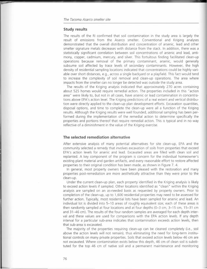
The Tacoma Asarco smelter site
Study results
The results of the RI confirmed that soil contamination in the study area is largely theresult of emissions from the Asarco smelter. Conventional and Kriging analysesdemonstrated that the overall distribution and concentration of arsenic, lead and other
smelter signature metals decreases with distance from the stack. In addition, there was astatistically significant correlation between soil concentrations of arsenic and lead, antimony, copper, cadmium, mercury, and silver. This fortuitous finding facilitated clean-upoperations because removal of the primary contaminant, arsenic, would generallysubsume soil affected by trace levels of secondary contaminants. However, the highdensity of residential sampling locations indicated that concentrations could be highly variable over short distances, e.g., across a single backyard or a playfield. This fact would tendto increase the complexity of soil removal and clean-up operations. The area whereimpacts from the smelter can no longer be detected was outside the study area.
The results of the Kriging analysis indicated that approximately 270 acres containingabout 525 homes would require remedial action. The properties included in this" actionarea" were likely to, but not in all cases, have arsenic or lead contamination in concentrations above EPA's action level. The Kriging predictions of a real extent and vertical distribution were directly applied to the clean-up plan development efforts. Excavation quantities,disposal options, and time to complete the clean-up were all a function of the Krigingresults. Although the Kriging results were well founded, additional sampling has been performed during the implementation of the remedial action to determine specifically theproperties and portions thereof that require remedial action. This is typical and in no wayreflective of a diminishment in the value of the Kriging exercise.
The selected remediation alternative
After extensive analysis of many potential alternatives for site clean-up, EPA and thecommunity selected a remedy that involves excavation of soils from properties that exceedEPA's action levels for arsenic and lead. Excavated areas are filled with clean soil and
replanted. A key component of the program is concern for the individual homeowner'sexisting plant material and garden artifacts, and every reasonable effort to restore affectedproperties to their original condition has been made, as shown in Figure 7. 4.
In general, most property owners have been pleased with the restoration and manyproperties post-remediation are more aesthetically attractive than they were prior to theclean-up.
Under the current clean-up plan, each property identified in the Kriging analysis is likelyto exceed action levels if sampled. Other locations identified as "clean" within the Kriginganalysis are sampled on an as-needed basis as requested by property owners. Prior tocompletion of the clean-up, up to 1,600 residential properties may need to be assessed forfurther action. Typically, most residential lots have been sampled for arsenic and lead. Anindividual lot is divided into 5-10 areas of roughly equivalent size; each of these areas isthen randomly sampled at four locations and at four depths (0-3 cm, 3-15 cm, 15-31 cmand 31--46 cm). The results of the four random samples are averaged for each depth interval and these values are used for comparisons with the EPA action levels. If any depthinterval for a particular sub-area indicates that contamination exceeds action levels, thenthat sub-area is excavated.
The majority of the properties requiring clean-up can be cleaned completely (i.e., soilabove the action levels will not remain), thus eliminating the need for long-term institutional controls on many private properties. Soils that exceed action levels below 46 cm arenot excavated. Where contamination exists below this depth, 46 cm of clean soil is substituted for the top 46 cm of native soil and a permanent maintenance and monitoring
76
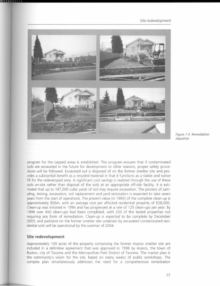
Site redevelopment
program for the capped areas is established. This program ensures that if contaminatedsoils are excavated in the future for development or other reasons, proper safety procedures will be followed. Excavated soil is disposed of on the former smelter site and provides a substantial benefit as a recycled material in that it functions as a stable and nativefill for the redeveloped area. A significant cost savings is realized through the use of thesesoils on-site rather than disposal of the soils at an appropriate off-site facility. It is estimated that up to 187,000 cubic yards of soil may require excavation. The process of sampling, testing, excavation, soil replacement and yard restoration is expected to take sevenyears from the start of operations. The present value (in 1993) of the complete clean-up isapproximately $56m, with an average cost per affected residential property of $58,000.Clean-up was initiated in 1994 and has progressed at a rate of 125 clean-ups per year. By1998 over 450 clean-ups had been completed, with 250 of the tested properties notrequiring any form of remediation. Clean-up is expected to be complete by December2003, and parkland on the former smelter site underlain by excavated contaminated residential soils will be operational by the summer of 2004.
Site redevelopment
Approximately 100 acres of the property comprising the former Asarco smelter site areincluded in a definitive agreement that was approved in 1996 by Asarco, the town ofRuston, city of Tacoma and the Metropolitan Park District of Tacoma. The master plan isthe community's vision for the site, based on many weeks of public workshops. Thecomplex plan simultaneously addresses the need for a comprehensive remediation
77
Figure 7.4 Remediationsequence
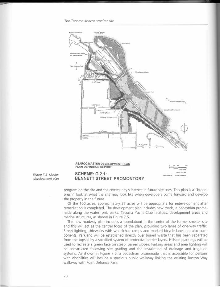
The Tacoma Asarco smelter site
Figure 7.5 Masterdevelopment plan
ASARCO MASTER DEVELOPMENT PLANPLAN DEFINITION REPORT
SCHEME: G 2.1:BENNETT STREET PROMONTORY
.......r---.- i
S•• 1thlMl
program on the site and the community's interest in future site uses. This plan is a "broadbrush" look at what the site may look like when developers come forward and developthe property in the future.
Of the 100 acres, approximately 37 acres will be appropriate for redevelopment afterremediation is completed. The development plan includes new roads, a pedestrian promenade along the waterfront, parks, Tacoma Yacht Club facilities, development areas andmarine structures, as shown in Figure 7.5.
The new roadway plan includes a roundabout in the center of the former smelter siteand this will act as the central focus of the plan, providing two lanes of one-way traffic.Street lighting, sidewalks with wheelchair ramps and marked bicycle lanes are also components. Parkland will be established directly over buried waste that has been separatedfrom the topsoil by a specified system of protective barrier layers. Hillside plantings will beused to recreate a green face on steep, barren slopes. Parking areas and area lighting willbe constructed following site grading and the installation of drainage and irrigationsystems. As shown in Figure 7.6, a pedestrian promenade that is accessible for personswith disabilities will include a spacious public walkway linking the existing Ruston Waywalkway with Point Defiance Park.
78
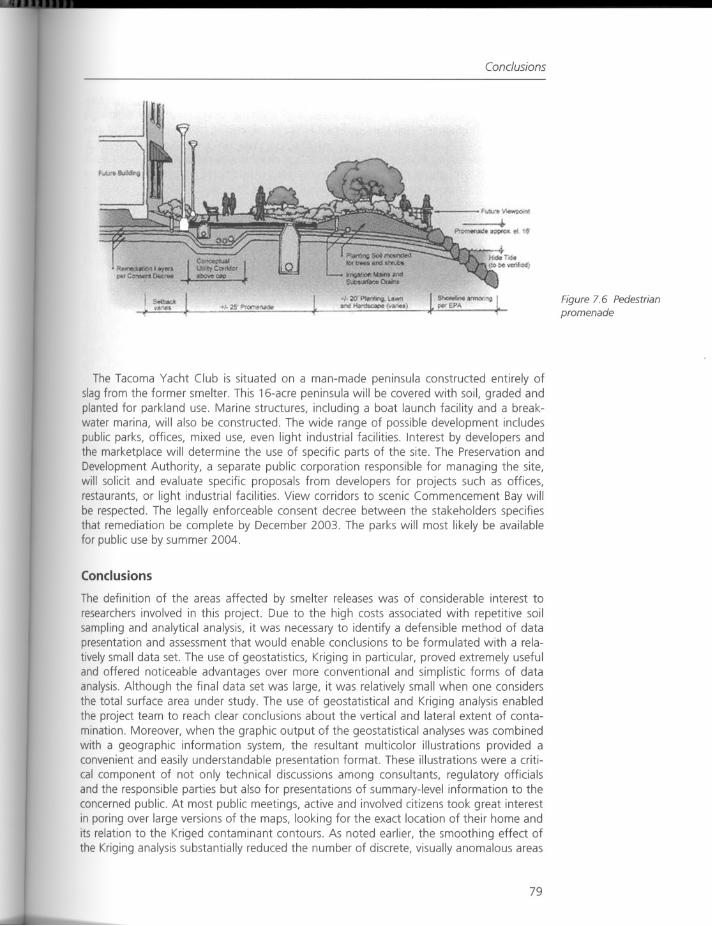
Conclusions
The Tacoma Yacht Club is situated on a man-made peninsula constructed entirely ofslag from the former smelter. This 16-acre peninsula will be covered with soil, graded andplanted for parkland use. Marine structures, including a boat launch facility and a breakwater marina, will also be constructed. The wide range of possible development includespublic parks, offices, mixed use, even light industrial facilities. Interest by developers andthe marketplace will determine the use of specific parts of the site. The Preservation andDevelopment Authority, a separate public corporation responsible for managing the site,will solicit and evaluate specific proposals from developers for projects such as offices,restaurants, or light industrial facilities. View corridors to scenic Commencement Bay willbe respected. The legally enforceable consent decree between the stakeholders specifiesthat remediation be complete by December 2003. The parks will most likely be availablefor public use by summer 2004.
Conclusions
The definition of the areas affected by smelter releases was of considerable interest toresearchers involved in this project. Due to the high costs associated with repetitive soilsampling and analytical analysis, it was necessary to identify a defensible method of datapresentation and assessment that would enable conclusions to be formulated with a relatively small data set. The use of geostatistics, Kriging in particular, proved extremely usefuland offered noticeable advantages over more conventional and simplistic forms of dataanalysis. Although the final data set was large, it was relatively small when one considersthe total surface area under study. The use of geostatistical and Kriging analysis enabledthe project team to reach clear conclusions about the vertical and lateral extent of contamination. Moreover, when the graphic output of the geostatistical analyses was combinedwith a geographic information system, the resultant multicolor illustrations provided aconvenient and easily understandable presentation format. These illustrations were a critical component of not only technical discussions among consultants, regulatory officialsand the responsible parties but also for presentations of summary-level information to theconcerned public. At most public meetings, active and involved citizens took great interestin poring over large versions of the maps, looking for the exact location of their home andits relation to the Kriged contaminant contours. As noted earlier, the smoothing effect ofthe Kriging analysis substantially reduced the number of discrete, visually anomalous areas
79
Figure 7.6 Pedestrianpromenade
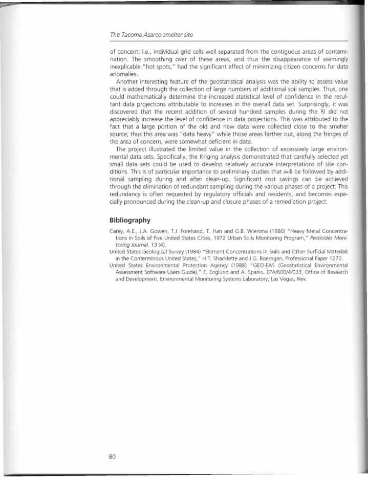
The Tacoma Asarco smelter site
of concern; i.e., individual grid cells well separated from the contiguous areas of contamination. The smoothing over of these areas, and thus the disappearance of seeminglyinexplicable "hot spots," had the significant effect of minimizing citizen concerns for dataanomalies.
Another interesting feature of the geostatistical analysis was the ability to assess valuethat is added through the collection of large numbers of additional soil samples. Thus, onecould mathematically determine the increased statistical level of confidence in the resultant data projections attributable to increases in the overall data set. Surprisingly, it wasdiscovered that the recent addition of several hundred samples during the RI did notappreciably increase the level of confidence in data projections. This was attributed to thefact that a large portion of the old and new data were collected close to the smeltersource; thus this area was "data heavy" while those areas farther out, along the fringes ofthe area of concern, were somewhat deficient in data.
The project illustrated the limited value in the collection of excessively large environmental data sets. Specifically, the Kriging analysis demonstrated that carefully selected yetsmall data sets could be used to develop relatively accurate interpretations of site conditions. This is of particular importance to preliminary studies that will be followed byadditional sampling during and after clean-up. Significant cost savings can be achievedthrough the elimination of redundant sampling during the various phases of a project. Thisredundancy is often requested by regulatory officials and residents, and becomes especially pronounced during the clean-up and closure phases of a remediation project.
Bibliography
Carey, A.E., JA Gowen, T.J. Forehand, T. Han and G.B. Wiersma (1980) "Heavy Metal Concentra
tions in Soils of Five United States Cities, 1972 Urban Soils Monitoring Program," Pesticides Monitoring Journal, 13 (4).
United States Geological Survey (1984) "Element Concentrations in Soils and Other Surficial Materialsin the Conterminous United States," H.T. Shacklette and J.G. Boerngen, Professional Paper 1270.
United States Environmental Protection Agency (1988) "GEO-EAS (Geostatistical EnvironmentalAssessment Software Users Guide)," E. Englund and A. Sparks. EPA/600/4/033, Office of Researchand Development, Environmental Monitoring Systems Laboratory, Las Vegas, Nev.
80
Response
Response
Manufacturing site information
As Steven Rock pointed out in Chapter 5, it is possible to take an environmental engineerand a designer who both have a professional interest in the same section of contaminatedland and for them to perceive the opportunities and constraints in completely differentways. This not only includes the demarcation and scope of the work itself, but the type ofknowledge that each seeks and demands as part of the record of site conditions andinformation.
In Tedaldi's essay the use of geostatistics is explained as a method of developing, as hestates, a "defensible method of data presentation and assessment that would enable conclusions to be formulated with a relatively small data set." This essay should be of extremeinterest to planners and designers in explaining an engineering method of using environmental site information as a working tool. This is true both in terms of its use in publicforums and as a means of assessing existing information and the ability of new information to render additional value or confidence to the conclusions. For those designers usedto the normal conventions of topographical surveys, photographic records of vegetation,soil maps and site sketches, this form of data manipulation may appear bewildering at first- how does a map become "smoothed," where do the contamination "hot-spots" go?
The design professions continue to address complex sites in other fields of endeavor.Surveying radically altering terrain through contour models and spot elevations, or thesubtle three-dimensional changes in vegetation patterns in hedgerows or woodlands,requires the adaptation or development of working tools in digital media and diagrammatic models. What makes Tedaldi's descriptions of special interest is the method of translating site knowledge concerning the extent of contaminated soil in three dimensions intousable and readable flat maps and plans.
81
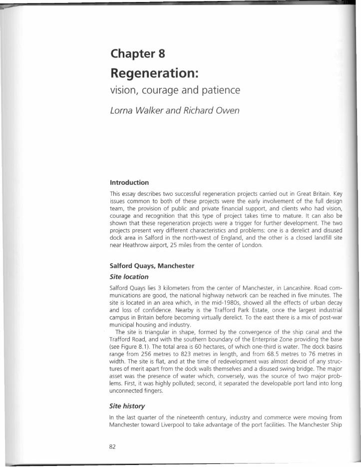
Chapter 8
Regeneration:vision, courage and patience
Lorna Walker and Richard Owen
Introduction
This essay describes two successful regeneration projects carried out in Great Britain. Keyissues common to both of these projects were the early involvement of the full designteam, the provision of public and private financial support, and clients who had vision,courage and recognition that this type of project takes time to mature. It can also beshown that these regeneration projects were a trigger for further development. The twoprojects present very different characteristics and problems: one is a derelict and disuseddock area in Salford in the north-west of England, and the other is a closed landfill sitenear Heathrow airport, 25 miles from the center of London.
Salford Quays, Manchester
Site location
Salford Quays lies 3 kilometers from the center of Manchester, in Lancashire. Road communications are good, the national highway network can be reached in five minutes. Thesite is located in an area which, in the mid-1980s, showed all the effects of urban decayand loss of confidence. Nearby is the Trafford Park Estate, once the largest industrialcampus in Britain before becoming virtually derelict. To the east there is a mix of post-warmunicipal housing and industry.
The site is triangular in shape, formed by the convergence of the ship canal and theTrafford Road, and with the southern boundary of the Enterprise Zone providing the base(see Figure 8.1). The total area is 60 hectares, of which one-third is water. The dock basinsrange from 256 metres to 823 metres in length, and from 68.5 metres to 76 metres inwidth. The site is flat, and at the time of redevelopment was almost devoid of any structures of merit apart from the dock walls themselves and a disused swing bridge. The majorasset was the presence of water which, conversely, was the source of two major problems. First, it was highly polluted; second, it separated the developable port land into longunconnected fingers.
Site history
In the last quarter of the nineteenth century, industry and commerce were moving fromManchester toward Liverpool to take advantage of the port facilities. The Manchester Ship
82
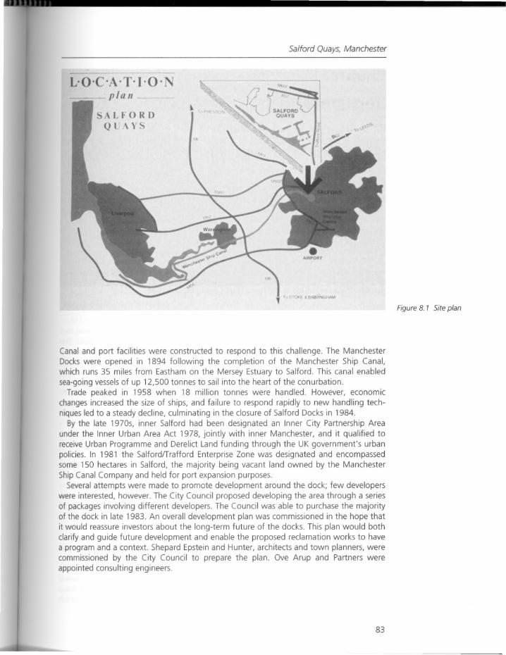
Salford Quays, Manchester
L'O' ·T·I·Q·plllll
Canal and port facilities were constructed to respond to this challenge. The ManchesterDocks were opened in 1894 following the completion of the Manchester Ship Canal,which runs 35 miles from Eastham on the Mersey Estuary to Salford. This canal enabledsea-going vessels of up 12,500 tonnes to sail into the heart of the conurbation.
Trade peaked in 1958 when 18 million tonnes were handled. However, economicchanges increased the size of ships, and failure to respond rapidly to new handling techniques led to a steady decline, culminating in the closure of Salford Docks in 1984.
By the late 1970s, inner Salford had been designated an Inner City Partnership Areaunder the Inner Urban Area Act 1978, jointly with inner Manchester, and it qualified toreceive Urban Programme and Derelict Land funding through the UK government's urbanpolicies. In 1981 the Salfordffrafford Enterprise Zone was designated and encompassedsome 150 hectares in Salford, the majority being vacant land owned by the ManchesterShip Canal Company and held for port expansion purposes.
Several attempts were made to promote development around the dock; few developerswere interested, however. The City Council proposed developing the area through a seriesof packages involving different developers. The Council was able to purchase the majorityof the dock in late 1983. An overall development plan was commissioned in the hope thatit would reassure investors about the long-term future of the docks. This plan would bothclarify and guide future development and enable the proposed reclamation works to havea program and a context. Shepard Epstein and Hunter, architects and town planners, werecommissioned by the City Council to prepare the plan. Ove Arup and Partners wereappointed consulting engineers.
83
Figure 8. 1 Site plan
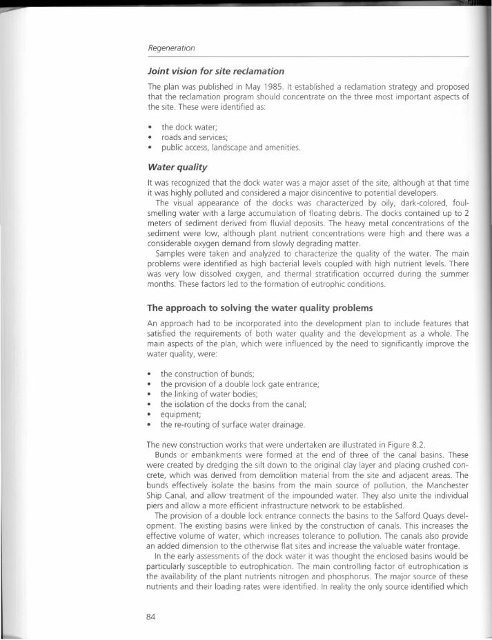
Regeneration
Joint vision for site reclamation
The plan was published in May 1985. It established a reclamation strategy and proposedthat the reclamation program should concentrate on the three most important aspects ofthe site. These were identified as:
• the dock water;• roads and services;
• public access, landscape and amenities.
Water quality
It was recognized that the dock water was a major asset of the site, although at that timeit was highly po/luted and considered a major disincentive to potential developers.
The visual appearance of the docks was characterized by oily, dark-colored, fou/smelling water with a large accumulation of floating debris. The docks contained up to 2meters of sediment derived from fluvial deposits. The heavy metal concentrations of thesediment were low, although plant nutrient concentrations were high and there was aconsiderable oxygen demand from slowly degrading matter.
Samples were taken and analyzed to characterize the quality of the water. The mainproblems were identified as high bacterial levels coupled with high nutrient levels. Therewas very low dissolved oxygen, and thermal stratification occurred during the summermonths. These factors led to the formation of eutrophic conditions.
The approach to solving the water quality problems
An approach had to be incorporated into the development plan to include features thatsatisfied the requirements of both water quality and the development as a whole. Themain aspects of the plan, which were influenced by the need to significantly improve thewater quality, were:
• the construction of bunds;
• the provision of a double lock gate entrance;• the linking of water bodies;• the isolation of the docks from the canal;• equipment;• the re-routing of surface water drainage.
The new construction works that were undertaken are illustrated in Figure 8.2.Bunds or embankments were formed at the end of three of the canal basins. These
were created by dredging the silt down to the original clay layer and placing crushed concrete, which was derived from demolition material from the site and adjacent areas. Thebunds effectively isolate the basins from the main source of pollution, the ManchesterShip Canal, and allow treatment of the impounded water. They also unite the individualpiers and allow a more efficient infrastructure network to be established.
The provision of a double lock entrance connects the basins to the Salford Quays development. The existing basins were linked by the construction of canals. This increases theeffective volume of water, which increases tolerance to pollution. The canals also providean added dimension to the otherwise flat sites and increase the valuable water frontage.
In the early assessments of the dock water it was thought the enclosed basins would beparticularly susceptible to eutrophication. The main controlling factor of eutrophication isthe availability of the plant nutrients nitrogen and phosphorus. The major source of thesenutrients and their loading rates were identified. In reality the only source identified which
84
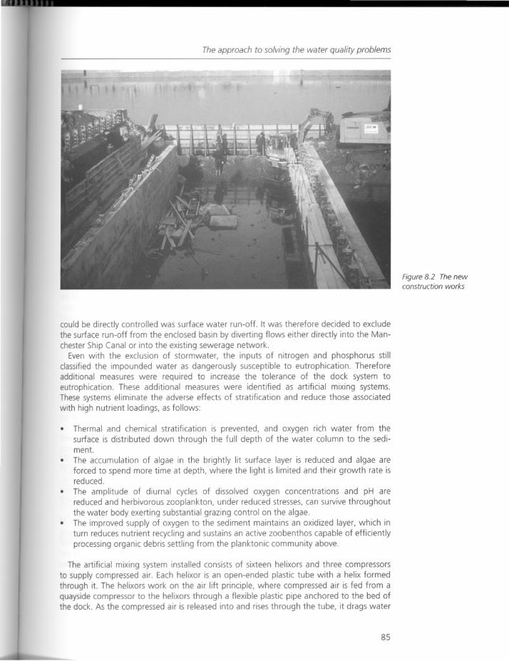
The approach to solving the water quality problems
could be directly controlled was surface water run-off. It was therefore decided to excludethe surface run-off from the enclosed basin by diverting flows either directly into the Manchester Ship Canal or into the existing sewerage network.
Even with the exclusion of stormwater, the inputs of nitrogen and phosphorus stillclassified the impounded water as dangerously susceptible to eutrophication. Thereforeadditional measures were required to increase the tolerance of the dock system toeutrophication. These additional measures were identified as artificial mixing systems.These systems eliminate the adverse effects of stratification and reduce those associatedwith high nutrient loadings, as follows:
Thermal and chemical stratification is prevented, and oxygen rich water from thesurface is distributed down through the full depth of the water column to the sediment.
• The accumulation of algae in the brightly lit surface layer is reduced and algae areforced to spend more time at depth, where the light is limited and their growth rate isreduced.
• The amplitude of diurnal cycles of dissolved oxygen concentrations and pH arereduced and herbivorous zooplankton, under reduced stresses, can survive throughoutthe water body exerting substantial grazing control on the algae.
• The improved supply of oxygen to the sediment maintains an oxidized layer, which inturn reduces nutrient recycling and sustains an active zoobenthos capable of efficientlyprocessing organic debris settling from the planktonic community above.
The artificial mixing system installed consists of sixteen helixors and three compressorsto supply compressed air. Each helixor is an open-ended plastic tube with a helix formedthrough it. The helixors work on the air lift principle, where compressed air is fed from aquayside compressor to the helixors through a flexible plastic pipe anchored to the bed ofthe dock. As the compressed air is released into and rises through the tube, it drags water
85
Figure 8.2 The newconstruction works
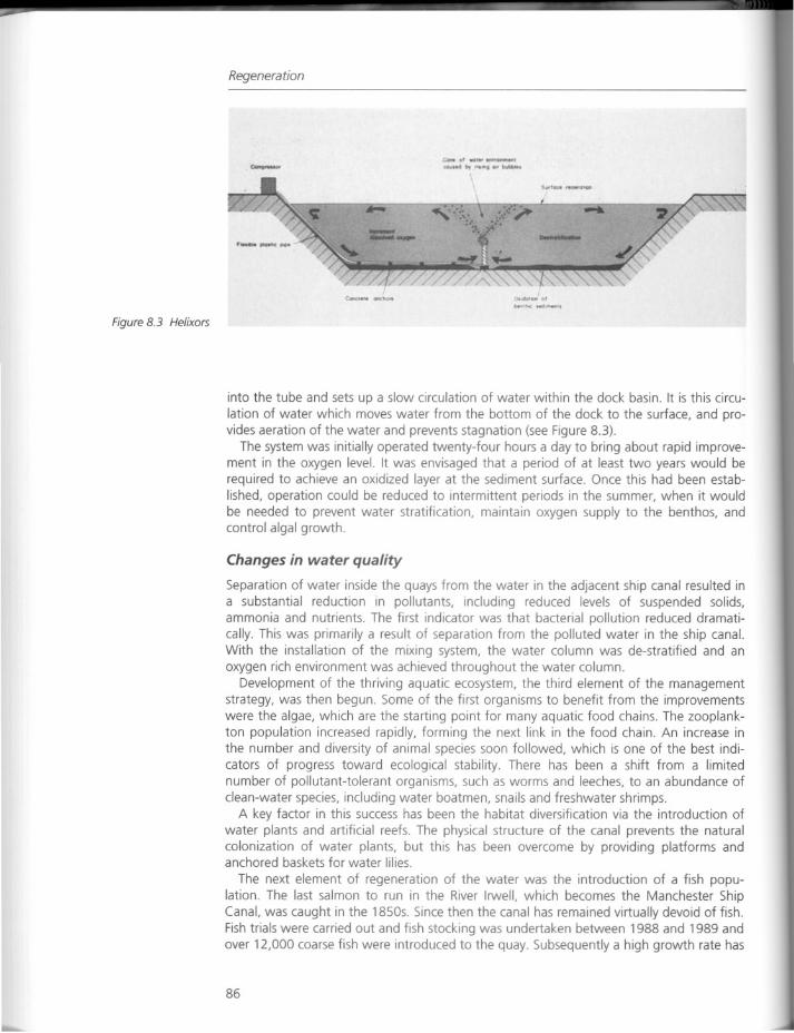
Regeneration
Figure 8.3 Helixors
----
into the tube and sets up a slow circulation of water within the dock basin. It is this circulation of water which moves water from the bottom of the dock to the surface, and provides aeration of the water and prevents stagnation (see Figure 8.3).
The system was initially operated twenty-four hours a day to bring about rapid improvement in the oxygen level. It was envisaged that a period of at least two years would berequired to achieve an oxidized layer at the sediment surface. Once this had been established, operation could be reduced to intermittent periods in the summer, when it wouldbe needed to prevent water stratification, maintain oxygen supply to the benthos, andcontrol algal growth.
Changes in water quality
Separation of water inside the quays from the water in the adjacent ship canal resulted ina substantial reduction in pollutants, including reduced levels of suspended solids,ammonia and nutrients. The first indicator was that bacterial pollution reduced dramatically. This was primarily a result of separation from the polluted water in the ship canal.With the installation of the mixing system, the water column was de-stratified and anoxygen rich environment was achieved throughout the water column.
Development of the thriving aquatic ecosystem, the third element of the managementstrategy, was then begun. Some of the first organisms to benefit from the improvementswere the algae, which are the starting point for many aquatic food chains. The zooplankton population increased rapidly, forming the next link in the food chain. An increase inthe number and diversity of animal species soon followed, which is one of the best indicators of progress toward ecological stability. There has been a shift from a limitednumber of pollutant-tolerant organisms, such as worms and leeches, to an abundance ofclean-water species, including water boatmen, snails and freshwater shrimps.
A key factor in this success has been the habitat diversification via the introduction ofwater plants and artificial reefs. The physical structure of the canal prevents the naturalcolonization of water plants, but this has been overcome by providing platforms andanchored baskets for water lilies.
The next element of regeneration of the water was the introduction of a fish population. The last salmon to run in the River Irwell, which becomes the Manchester ShipCanal, was caught in the 1850s. Since then the canal has remained virtually devoid of fish.Fish trials were carried out and fish stocking was undertaken between 1988 and 1989 andover 12,000 coarse fish were introduced to the quay. Subsequently a high growth rate has
86
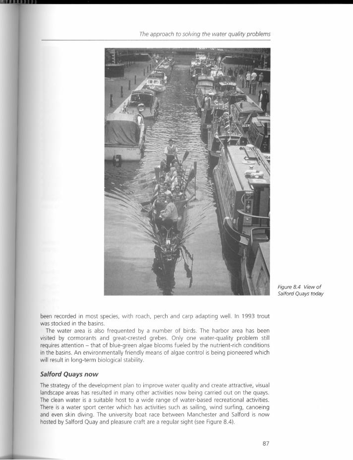
The approach to solving the water quality problems
been recorded in most species, with roach, perch and carp adapting well. In 1993 troutwas stocked in the basins.
The water area is also frequented by a number of birds. The harbor area has beenvisited by cormorants and great-crested grebes. Only one water-quality problem stillrequires attention - that of blue-green algae blooms fueled by the nutrient-rich conditionsin the basins. An environmentally friendly means of algae control is being pioneered whichwill result in long-term biological stability.
Salford Quays now
The strategy of the development plan to improve water quality and create attractive, visuallandscape areas has resulted in many other activities now being carried out on the quays.The clean water is a suitable host to a wide range of water-based recreational activities.There is a water sport center which has activities such as sailing, wind surfing, canoeingand even skin diving. The university boat race between Manchester and Salford is nowhosted by Salford Quay and pleasure craft are a regular sight (see Figure 8.4).
87
Figure 8.4 View ofSalford Quays today
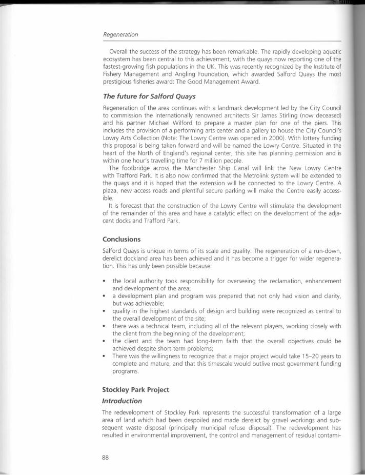
Regeneration
Overall the success of the strategy has been remarkable. The rapidly developing aquaticecosystem has been central to this achievement, with the quays now reporting one of thefastest-growing fish populations in the UK. This was recently recognized by the Institute ofFishery Management and Angling Foundation, which awarded Salford Quays the mostprestigious fisheries award: The Good Management Award.
The future for Salford Quays
Regeneration of the area continues with a landmark development led by the City Councilto commission the internationally renowned architects Sir James Stirling (now deceased)and his partner Michael Wilford to prepare a master plan for one of the piers. Thisincludes the provision of a performing arts center and a gallery to house the City Council'sLowry Arts Collection (Note: The Lowry Centre was opened in 2000). With lottery fundingthis proposal is being taken forward and will be named the Lowry Centre. Situated in theheart of the North of England's regional center, this site has planning permission and iswithin one hour's travelling time for 7 million people.
The footbridge across the Manchester Ship Canal will link the New Lowry Centrewith Trafford Park. It is also now confirmed that the Metrolink system will be extended tothe quays and it is hoped that the extension will be connected to the Lowry Centre Aplaza, new access roads and plentiful secure parking will make the Centre easily accessible.
It is forecast that the construction of the Lowry Centre will stimulate the developmentof the remainder of this area and have a catalytic effect on the development of the adjacent docks and Trafford Park.
Conclusions
Salford Quays is unique in terms of its scale and quality. The regeneration of a run-down,derelict dockland area has been achieved and it has become a trigger for wider regeneration. This has only been possible because:
• the local authority took responsibility for overseeing the reclamation, enhancementand development of the area;
• a development plan and program was prepared that not only had vision and clarity,but was achievable;
• quality in the highest standards of design and building were recognized as central tothe overall development of the site;
• there was a technical team, including all of the relevant players, working closely withthe client from the beginning of the development;
• the client and the team had long-term faith that the overall objectives could beachieved despite short-term problems;
• There was the willingness to recognize that a major project would take 15-20 years tocomplete and mature, and that this timescale would outlive most government fundingprograms.
Stockley Park Project
Introduction
The redevelopment of Stockley Park represents the successful transformation of a largearea of land which had been despoiled and made derelict by gravel workings and subsequent waste disposal (principally municipal refuse disposal). The redevelopment hasresulted in environmental improvement, the control and management of residual contami-
88
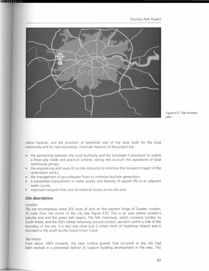
Stockley Park Project
nation hazards, and the provision of beneficial uses of the land, both for the localcommunity and for new businesses. Particular features of the project are:
the partnership between the Local Authority and the Developer Consortium to realizea financially viable and practical scheme, taking into account the aspirations of localcommunity groups;
• the engineering and reuse of on-site resources to minimize the transport impact of thereclamation works;
• the management of groundwater flows to minimize leachate generation;• a substantial improvement in water quality and diversity of aquatic life in an adjacent
water course;
• improved transport links and recreational access across the area.
Site description
Location
The site encompasses some 350 acres of land on the western fringe of Greater London,25 miles from the center of the city (see Figure 8.5). This is an area where London'ssuburbs end and the green belt begins. The M4 motorway, which connects London toSouth Wales, and the M25 orbital motorway around London, are both within a mile of theboundary of the site. It is also very close Gust 2 miles) north of Heathrow Airport and isbounded to the south by the Grand Union Canal.
Site historyFrom about 1850 onwards, the near surface gravels that occurred at the site hadbeen worked in a piecemeal fashion to support building development in the area. This
89
Figure 8.5 Site locationplan
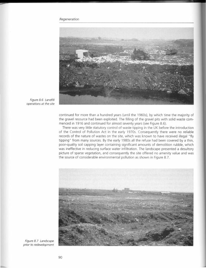
Figure 8.6 Landfilloperations at the site
Figure 8.7 Landscapeprior to redevelopment
Regeneration
continued for more than a hundred years (until the 1960s), by which time the majority ofthe gravel resource had been exploited. The filling of the gravel pits with solid waste commenced in 1916 and continued for almost seventy years (see Figure 8.6).
There was very little statutory control of waste tipping in the UK before the introductionof the Control of Pollution Act in the early 1970s. Consequently there were no reliablerecords of the nature of wastes on the site, which was known to have received illegal "flytipping" from many sources. By the early 1980s all the refuse had been covered by a thin,poor-quality soil capping layer containing significant amounts of demolition rubble, whichwas ineffective in reducing surface water infiltration. The landscape presented a desultorypicture of sparse vegetation, and consequently the site offered no amenity value and wasthe source of considerable environmental pollution as shown in Figure 8.7.
90
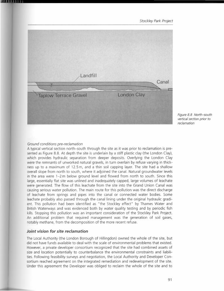
Stockley Park Project
Landfill
Canal
Taplow Terrace Gravel London Clay
Figure 8.8 North-southvertical section prior toreclamation
Ground conditions pre-reclamationA typical vertical section north-south through the site as it was prior to reclamation is presented as Figure 8.8. At depth the site is underlain by a stiff plastic clay (the London Clay),which provides hydraulic separation from deeper deposits. Overlying the London Claywere the remnants of unworked natural gravels, in turn overlain by refuse varying in thickness up to a maximum of 12.5 m, and a thin soil capping layer. The site had a shallowoverall slope from north to south, where it adjoined the canal. Natural groundwater levelsin the area were 1-2 m below ground level and flowed from north to south. Since thislarge, essentially flat site was unlined and inadequately capped, large volumes of leachatewere generated. The flow of this leachate from the site into the Grand Union Canal wascausing serious water pollution. The main route for this pollution was the direct dischargeof leachate from springs and pipes into the canal or connected water bodies. Someleachate probably also passed through the canal lining under the original hydraulic gradient. This pollution had been identified as "the Stockley effect" by Thames Water andBritish Waterways and was evidenced both by water quality testing and by periodic fishkills. Stopping this pollution was an important consideration of the Stockley Park Project.An additional problem that required management was the generation of soil gases,notably methane, from the decomposition of the more recent refuse.
Joint vision for site reclamation
The Local Authority (the London Borough of Hillingdon) owned the whole of the site, butdid not have funds available to deal with the scale of environmental problems that existed.However, a private developer consortium recognized that the site had combined assets ofsize and location potentially to counterbalance the environmental constraints and liabilities. Following feasibility surveys and negotiation, the Local Authority and Developer Consortium reached agreement on the integrated remediation and redevelopment of the site.Under this agreement the Developer was obliged to reclaim the whole of the site and to
91
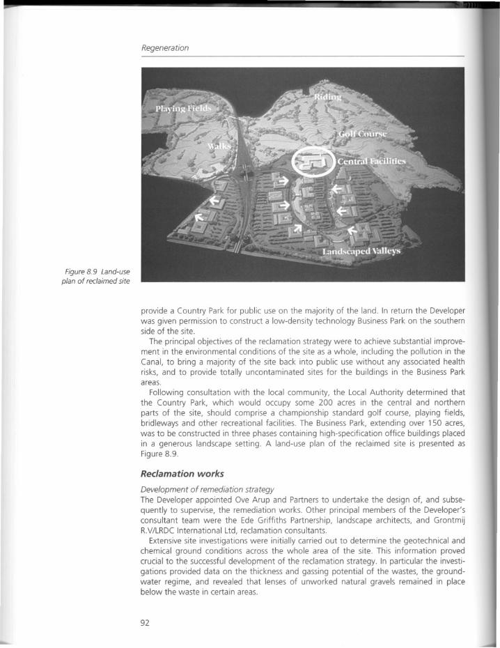
Figure 8.9 Land-useplan of reclaimed site
Regeneration
provide a Country Park for public use on the majority of the land. In return the Developerwas given permission to construct a low-density technology Business Park on the southernside of the site.
The principal objectives of the reclamation strategy were to achieve substantial improvement in the environmental conditions of the site as a whole, including the pollution in theCanal, to bring a majority of the site back into public use without any associated healthrisks, and to provide totally uncontaminated sites for the buildings in the Business Parkareas.
Following consultation with the local community, the Local Authority determined thatthe Country Park, which would occupy some 200 acres in the central and northernparts of the site, should comprise a championship standard golf course, playing fields,bridleways and other recreational facilities. The Business Park, extending over 150 acres,was to be constructed in three phases containing high-specification office buildings placedin a generous landscape setting. A land-use plan of the reclaimed site is presented asFigure 8.9.
Reclamation works
Development of remediation strategyThe Developer appointed Ove Arup and Partners to undertake the design of, and subsequently to supervise, the remediation works. Other principal members of the Developer'sconsultant team were the Ede Griffiths Partnership, landscape architects, and GrontmijRV/LRDC International Ltd, reclamation consultants.
Extensive site investigations were initially carried out to determine the geotechnical andchemical ground conditions across the whole area of the site. This information provedcrucial to the successful development of the reclamation strategy. In particular the investigations provided data on the thickness and gassing potential of the wastes, the groundwater regime, and revealed that lenses of unworked natural gravels remained in placebelow the waste in certain areas.
92
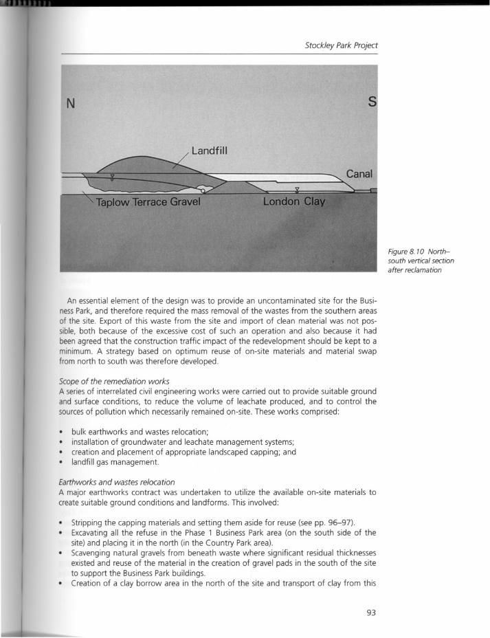
N
Landfill
Stockley Park Project
s
Figure 8. 10 Northsouth vertical sectionafter reclamation
An essential element of the design was to provide an uncontaminated site for the BusinessPark, and therefore required the mass removal of the wastes from the southern areasof the site. Export of this waste from the site and import of clean material was not possible, both because of the excessive cost of such an operation and also because it hadbeen agreed that the construction traffic impact of the redevelopment should be kept to aminimum. A strategy based on optimum reuse of on-site materials and material swapfrom north to south was therefore developed.
Scope of the remediation worksA series of interrelated civil engineering works were carried out to provide suitable groundand surface conditions, to reduce the volume of leachate produced, and to control thesources of pollution which necessarily remained on-site. These works comprised:
bulk earthworks and wastes relocation;installation of groundwater and leachate management systems;
• creation and placement of appropriate landscaped capping; and• landfill gas management.
Earthworks and wastes relocation
A major earthworks contract was undertaken to utilize the available on-site materials tocreate suitable ground conditions and landforms. This involved:
• Stripping the capping materials and setting them aside for reuse (see pp. 96-97).Excavating all the refuse in the Phase 1 Business Park area (on the south side of thesite) and placing it in the north (in the Country Park area).
• Scavenging natural gravels from beneath waste where significant residual thicknessesexisted and reuse of the material in the creation of gravel pads in the south of the siteto support the Business Park buildings.
• Creation of a clay borrow area in the north of the site and transport of clay from this
93
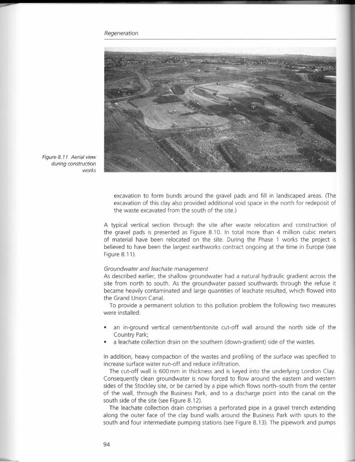
Figure 8. 11 Aerial viewduring construction
works
Regeneration
excavation to form bunds around the gravel pads and fill in landscaped areas. (Theexcavation of this clay also provided additional void space in the north for redeposit ofthe waste excavated from the south of the site.)
A typical vertical section through the site after waste relocation and construction ofthe gravel pads is presented as Figure 8.10. In total more than 4 million cubic metersof material have been relocated on the site. During the Phase 1 works the project isbelieved to have been the largest earthworks contract ongoing at the time in Europe (seeFigure 8.11).
Groundwater and leachate managementAs described earlier, the shallow groundwater had a natural hydraulic gradient across thesite from north to south. As the groundwater passed southwards through the refuse itbecame heavily contaminated and large quantities of leachate resulted, which flowed intothe Grand Union Canal.
To provide a permanent solution to this pollution problem the following two measureswere installed:
• an in-ground vertical cement/bentonite cut-off wall around the north side of theCountry Park;
• a leachate collection drain on the southern (down-gradient) side of the wastes.
In addition, heavy compaction of the wastes and profiling of the surface was specified toincrease surface water run-off and reduce infiltration.
The cut-off wall is 600 mm in thickness and is keyed into the underlying London Clay.Consequently clean groundwater is now forced to flow around the eastern and westernsides of the Stockley site, or be carried by a pipe which flows north-south from the centerof the wall, through the Business Park, and to a discharge point into the canal on thesouth side of the site (see Figure 8.12).
The leachate collection drain comprises a perforated pipe in a gravel trench extendingalong the outer face of the clay bund walls around the Business Park with spurs to thesouth and four intermediate pumping stations (see Figure 8.13). The pipework and pumps
94
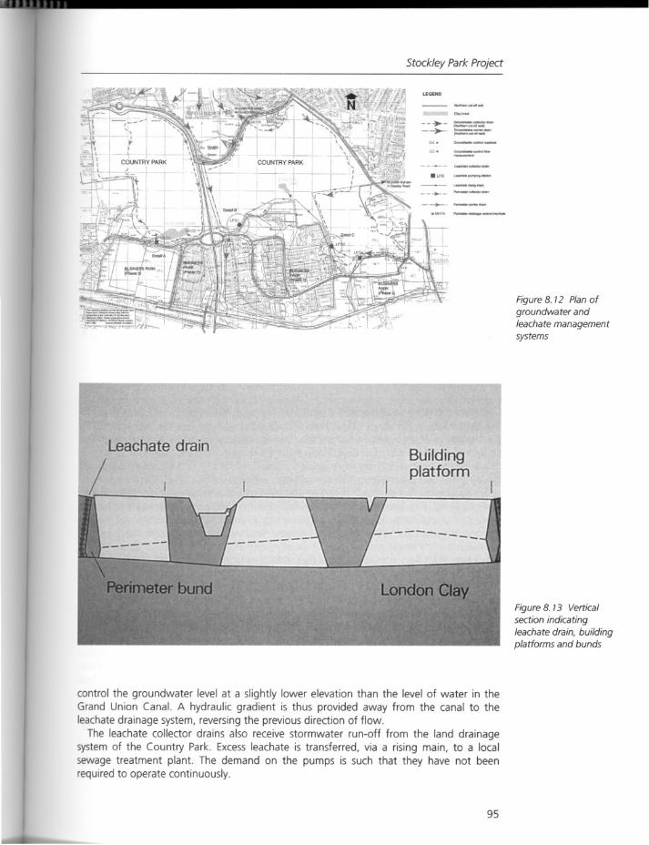
Stockley Park Project
LEGEND
--.-_._>- ..
-'"
-- ..•..-
---===-
~ ...•---
Figure 8. 12 Plan ofgroundwater andleachate managementsystems
Leachate drainBuildingplatform
Figure 8. 13 Vertical
section indicatingleachate drain, buildingplatforms and bunds
control the groundwater level at a slightly lower elevation than the level of water in theGrand Union Canal. A hydraulic gradient is thus provided away from the canal to theleachate drainage system, reversing the previous direction of flow.
The leachate collector drains also receive stormwater run-off from the land drainagesystem of the Country Park. Excess leachate is transferred, via a rising main, to a localsewage treatment plant. The demand on the pumps is such that they have not beenrequired to operate continuously.
95

Regeneration
The diversion of groundwater through-flow, together with the accumulation and compaction of the waste into a smaller plan area, the provision of a thicker and more profiledand vegetated cap in the Country Park area, and an increased density of the waste, hasvery significantly reduced the volumes of leachate generated by the site. Also the threat tothe quality of the water in the Grand Union Canal has been eliminated by the hydraulicgradient reversal, removal of excess leachate to a treatment works, and the physicalbarrier of the bunded and uncontaminated Business Park between the canal and thewaste.
Landscape development in the Country Park
ObjectivesThe long-term objectives for the Stockley Country Park were to create:
• a public open space and landscape that contains semi-natural habitats where naturalregeneration is encouraged;
• a range of recreational facilities within a country-like environment for the pleasure andrelaxation of the community.
The major elements of the landscape design within the context of site reclamation were:
• landform and topsoil construction;• planting and seeding.
Landform and topsoil constructionThe new landform for the Country Park, including the golf course, has been created bythe transfer of refuse from the Business Park area. A topographically interesting landformwas constructed on what was previously a flat area.
The successful development of vegetation in the Country Park required management oflandfill gases and the design of an appropriate medium in which trees, shrubs and grasscould be grown. The nutrient, moisture and physical support demands of trees, shrubsand grass vary, but construction considerations dictated that different topsoil constructionprofiles for different vegetation types were impracticable. Therefore a uniform"maximum" topsoil construction depth capable of supporting trees, shrubs and grass wasadopted over the whole area.
For the bulk filling operations the newer refuse was placed below the older refuse, inorder to reduce the risk of damage to vegetation due to methane generation.
The subsoil and topsoil capping layer for the Country Park was manufactured using, asfar as possible, materials already on-site. This avoided the necessity of importing large andexpensive quantities of topsoil.
The available on-site materials were essentially the refuse and the capping which hadbeen scraped off the refuse areas. In addition, sludge cake with low levels of heavy metalswas available from two local sewage treatment works.
In essence, the growing medium consists of two layers. The lowest layer, 750 mm thick,is composed of Type B former capping material mixed with aged refuse. Above this, TypeA former capping material, mixed with sludge cake, was placed to a thickness of 550 mm.The basic difference between Types A and B is that the former contains no more than 40percent gravel and stones, as a result of stone picking, undertaken during construction, toimprove the quality of the final product.
The water retention capacity of the soil profile has been estimated at 250 mm which,together with the average rainfall of 250 mm during the growing season, provides adequate water for plants during dry periods when the groundwater level is low.
96
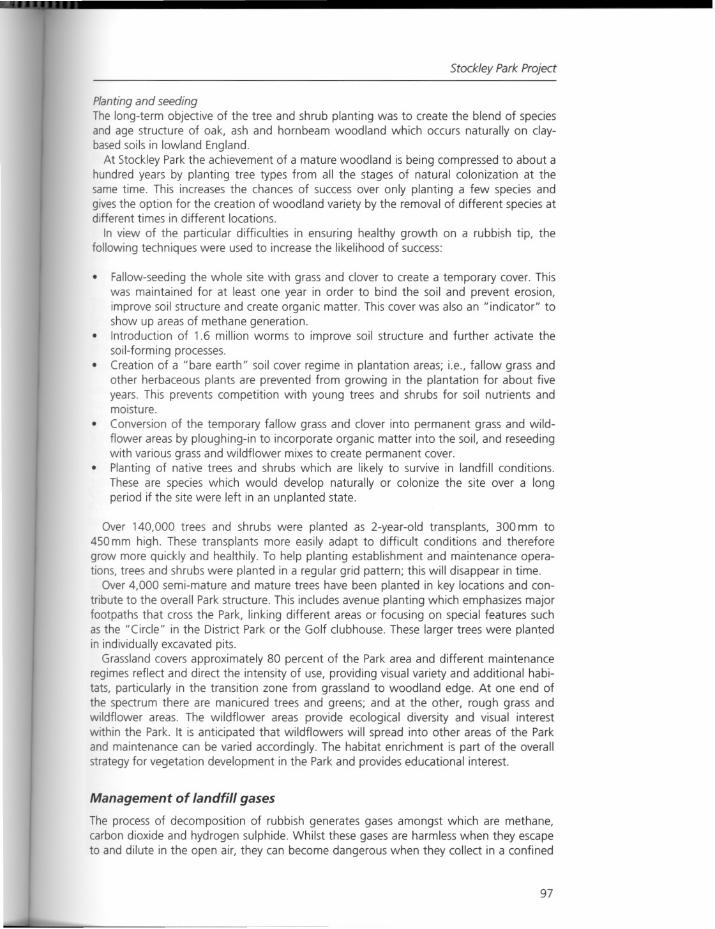
Stockley Park Project
Planting and seedingThe long-term objective of the tree and shrub planting was to create the blend of speciesand age structure of oak, ash and hornbeam woodland which occurs naturally on c1aybased soils in lowland England.
At Stockley Park the achievement of a mature woodland is being compressed to about ahundred years by planting tree types from all the stages of natural colonization at thesame time. This increases the chances of success over only planting a few species andgives the option for the creation of woodland variety by the removal of different species atdifferent times in different locations.
In view of the particular difficulties in ensuring healthy growth on a rubbish tip, thefollowing techniques were used to increase the likelihood of success:
• Fallow-seeding the whole site with grass and clover to create a temporary cover. Thiswas maintained for at least one year in order to bind the soil and prevent erosion,improve soil structure and create organic matter. This cover was also an "indicator" toshow up areas of methane generation.Introduction of 1.6 million worms to improve soil structure and further activate thesoil-forming processes.
• Creation of a "bare earth" soil cover regime in plantation areas; i.e., fallow grass andother herbaceous plants are prevented from growing in the plantation for about fiveyears. This prevents competition with young trees and shrubs for soil nutrients andmoisture.
• Conversion of the temporary fallow grass and clover into permanent grass and wildflower areas by ploughing-in to incorporate organic matter into the soil, and reseedingwith various grass and wildflower mixes to create permanent cover.
• Planting of native trees and shrubs which are likely to survive in landfill conditions.These are species which would develop naturally or colonize the site over a longperiod if the site were left in an unplanted state.
Over 140,000 trees and shrubs were planted as 2-year-old transplants, 300 mm to450 mm high. These transplants more easily adapt to difficult conditions and thereforegrow more quickly and healthily. To help planting establishment and maintenance operations, trees and shrubs were planted in a regular grid pattern; this will disappear in time.
Over 4,000 semi-mature and mature trees have been planted in key locations and contribute to the overall Park structure. This includes avenue planting which emphasizes majorfootpaths that cross the Park, linking different areas or focusing on special features suchas the "Circle" in the District Park or the Golf clubhouse. These larger trees were plantedin individually excavated pits.
Grassland covers approximately 80 percent of the Park area and different maintenanceregimes reflect and direct the intensity of use, providing visual variety and additional habitats, particularly in the transition zone from grassland to woodland edge. At one end ofthe spectrum there are manicured trees and greens; and at the other, rough grass andwildflower areas. The wildflower areas provide ecological diversity and visual interestwithin the Park. It is anticipated that wildflowers will spread into other areas of the Parkand maintenance can be varied accordingly. The habitat enrichment is part of the overallstrategy for vegetation development in the Park and provides educational interest.
Management of landfill gases
The process of decomposition of rubbish generates gases amongst which are methane,carbon dioxide and hydrogen sulphide. Whilst these gases are harmless when they escapeto and dilute in the open air, they can become dangerous when they collect in a confined
97
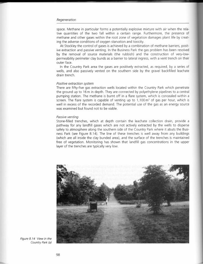
Figure 8. 14 View in the
Country Park (a)
Regeneration
space. Methane in particular forms a potentially explosive mixture with air when the relative quantities of the two fall within a certain range. Furthermore, the presence ofmethane and other gases within the root zone of vegetation damages plant life by creating the adverse conditions of oxygen starvation and toxicity.
At Stockley the control of gases is achieved by a combination of methane barriers, positive extraction and passive venting. In the Business Park the gas problem has been resolvedby the removal of source materials (the rubbish) and the construction of very-Iowpermeability perimeter clay bunds as a barrier to lateral ingress, with a vent trench on theirouter face.
In the Country Park area the gases are positively extracted, as required, by a series ofwells, and also passively vented on the southern side by the gravel backfilled leachatedrain trench.
Positive extraction system
There are fifty-five gas extraction wells located within the Country Park which penetratethe ground up to 16 m in depth. They are connected by polyethylene pipelines to a centralpumping station. The methane is burnt off in a flare system, which is concealed within ascreen. The flare system is capable of venting up to 1,100 m3 of gas per hour, which iswell in excess of the recorded demand The potential use of the gas as an energy sourcewas examined but found not to be viable.
Passive venting
Stone-filled trenches, which at depth contain the leachate collection drain, provide apathway for any landfill gases which are not actively extracted by the wells to dispersesafely to atmosphere along the southern side of the Country Park where it abuts the Business Park (see Figure 8.14). The line of these trenches is well away from any buildings(which are all inside the clay bunded area), and the surface of the trenches is maintainedfree of vegetation. Monitoring has shown that landfill gas concentrations in the upperlayer of the trenches are typically very low.
98
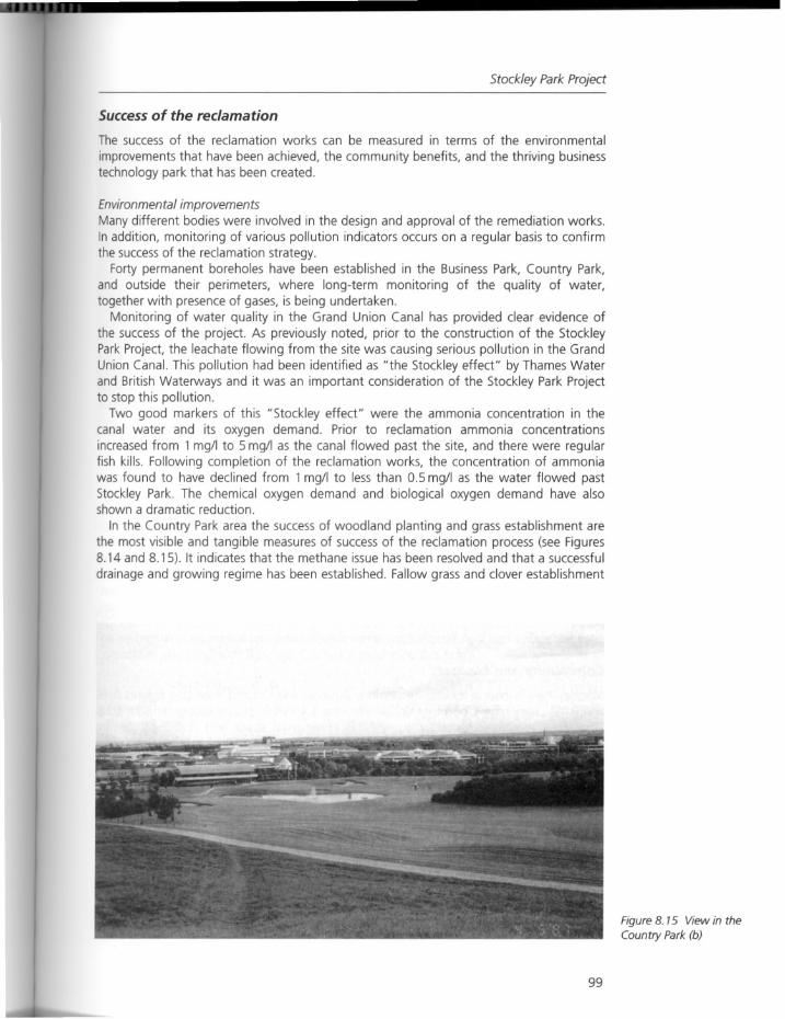
Stockley Park Project
Successof the reclamation
The success of the reclamation works can be measured in terms of the environmental
improvements that have been achieved, the community benefits, and the thriving businesstechnology park that has been created.
Environmental improvementsMany different bodies were involved in the design and approval of the remediation works.In addition, monitoring of various pollution indicators occurs on a regular basis to confirmthe successof the reclamation strategy.
Forty permanent boreholes have been established in the Business Park, Country Park,and outside their perimeters, where long-term monitoring of the quality of water,together with presence of gases, is being undertaken.
Monitoring of water quality in the Grand Union Canal has provided clear evidence ofthe success of the project. As previously noted, prior to the construction of the StockleyPark Project, the leachate flowing from the site was causing serious pollution in the GrandUnion Canal. This pollution had been identified as "the Stockley effect" by Thames Waterand British Waterways and it was an important consideration of the Stockley Park Projectto stop this pollution.
Two good markers of this "Stockley effect" were the ammonia concentration in thecanal water and its oxygen demand. Prior to reclamation ammonia concentrationsincreased from 1 mg/l to 5 mg/l as the canal flowed past the site, and there were regularfish kills. Following completion of the reclamation works, the concentration of ammoniawas found to have declined from 1 mg/l to less than 0.5 mg/I as the water flowed pastStockley Park. The chemical oxygen demand and biological oxygen demand have alsoshown a dramatic reduction.
In the Country Park area the success of woodland planting and grass establishment arethe most visible and tangible measures of success of the reclamation process (see Figures8.14 and 8.15). It indicates that the methane issue has been resolved and that a successful
drainage and growing regime has been established. Fallow grass and clover establishment
99
Figure 8. 15 View in the
Country Park (b)
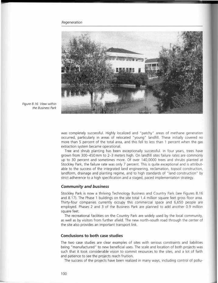
Figure 8. 76 View withinthe Business Park
Regeneration
was completely successful. Highly localized and "patchy" areas of methane generationoccurred, particularly in areas of relocated "young" landfill. These initially covered nomore than 5 percent of the total area, and this fell to less than 1 percent when the gasextraction system became operational.
Tree and shrub planting has been exceptionally successful. In four years, trees havegrown from 300-450 mm to 2-3 meters high. On landfill sites failure rates are commonlyup to 30 percent and sometimes more. Of over 140,0000 trees and shrubs planted atStockley Park, the failure rate was only 7 percent. This is quite exceptional and is attributable to the success of the integrated land engineering, reclamation, topsoil construction,landform, drainage and planting regime, and to high standards of "land construction" bystrict adherence to a high specification and a staged, paced implementation strategy.
Community and business
Stockley Park is now a thriving Technology Business and Country Park (see Figures 8.16and 8.17). The Phase 1 buildings on the site total 1.4 million square feet gross floor area.Thirty-four companies currently occupy this commercial space and 6,650 people areemployed. Phases 2 and 3 of the Business Park are planned to add another 0.9 millionsquare feet.
The recreational facilities on the Country Park are widely used by the local community,as well as by visitors from further afield. The new north-south road through the center ofthe site also provides an important transport link.
Conclusions to both case studies
The two case studies are clear examples of sites with serious constraints and liabilitiesbeing "manufactured" to new beneficial uses. The scale and location of both projects wassuch that it took considerable vision to commit resources to the sites, and a lot of faith
and patience to see the projects reach fruition.The success of the projects have been realized in many ways, including control of pollu-
100
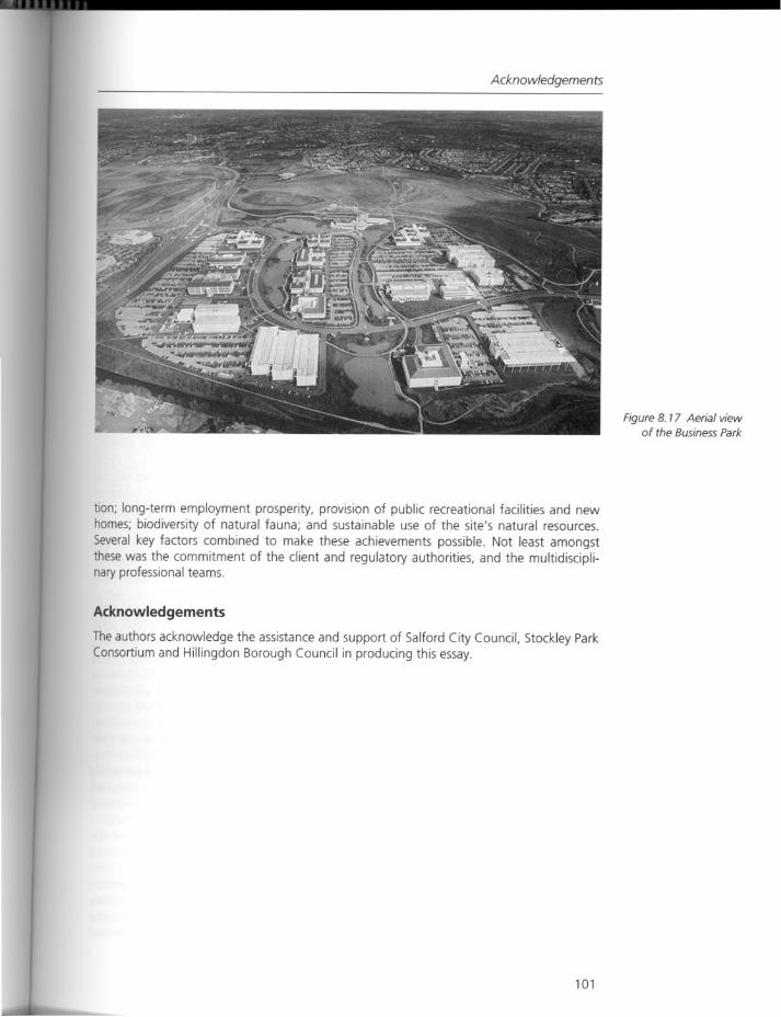
Acknowledgements
tion; long-term employment prosperity, provision of public recreational facilities and newhomes; biodiversity of natural fauna; and sustainable use of the site's natural resources.
Several key factors combined to make these achievements possible. Not least amongstthese was the commitment of the client and regulatory authorities, and the multidisciplinary professional teams.
Acknowledgements
The authors acknowledge the assistance and support of Salford City Council, Stockley ParkConsortium and Hillingdon Borough Council in producing this essay.
101
Figure 8. 17 Aerial viewof the Business Park
Regeneration
Response
Integration through an interdisciplinary approach?
The two case studies, Salford Quays and Stockley Park, presented by Lorna Walker andRichard Owen, respectively, offer compelling examples of how the multidisciplinaryapproaches used in both projects were critical to the regeneration of these large-scale,severely degraded sites. It was determined in both projects that a mixed-use solution withrecreational amenities would provide economic viability. A water sports center and an artscenter were proposed in Salford Quays, and an extensive recreational park and businesspark were embraced by the community and implemented at Stockley Park. The scale ofthe projects, the severity of the contamination and the complexity of the mixed-use programs at both sites required a diverse team of designers, planners, economists and scientists to bring their shared expertise to the table and integrate the remediation of the landand water with the economic and civic goals of the projects.
The two sites are contextually very different. Salford Quays is dominated by waterrequiring extensive hydrological and aquatic remediation. Stockley Park, a former inlandgravel pit, later developed as a solid waste dump, necessitated extensive subsurfacegroundwater and leachate mediation, regrading and soil treatment, and gas control andextraction. They both raise some common site specific issues: notably their site remediation and programmatic developments are closely tied to market rate economics. A moreexpanded look at the economics is found in an overview of urban development relatedissues in the essay in Chapter 6, "Engineering Urban Brownfield Development: Examplesfrom Pittsburgh," by McNeil and Lange. In the latter study the funding partnershipbetween the public and private sectors, and the reliance upon interdisciplinary designteams, is elaborated upon. In Salford Quays, improved water quality was fundamental toany future revitalization efforts, and several innovative technologies were created toenhance the water quality and assure that all economic and building development couldfollow.
As is common in most remediation projects the pivotal question to resolve is how multiple problems can be re-seen and addressed to become complementary assets. Themethods used in both Salford Quays and Stockley Park reflect this multiple solutionapproach required to meet a complexity of issues. Instead of using a single technology,the design team in the Salford Quay project incorporated multiple methods to begin toimprove the water quality using technologies to simulate natural features. Strategiesinclude artificial reefs, structures to support aquatic plants and the introduction of oxygenand aeration; these efforts grounded in both environmental engineering and the scienceof ecology. By introducing the aquatic life and utilizing the natural food chain to increasethe clean-water species, the team designed a long-term management plan aimed at continued improvements in water quality. Innovative solutions were developed by a close collaboration between designers, engineers and scientists. Recreation added a key andcomplementary component. The remediation of Salford Quays with costly water qualityimprovements was economically acceptable in part because recreational opportunitieswere created. In Stockley Park, multiple benefits were also critical to acceptance of theproject by the local community. These include a golf course, pedestrian and bicycle trails,ballfields and small playground facilities
A full and accurate understanding of the site contamination early in the design processwas important in both projects. The multiple methods that were used in Stockley Parkresponded not only to the flow patterns of water migrating through and off the site, butalso to the differing soil densities and specific locations of contamination. An effective and
102
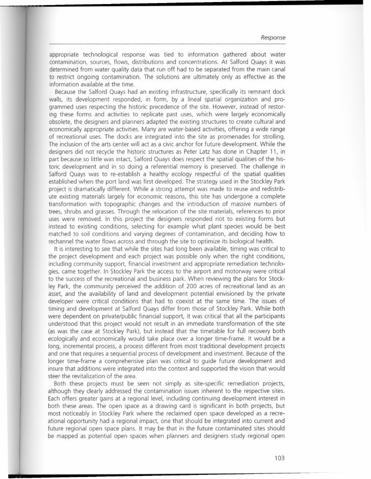
Response
appropriate technological response was tied to information gathered about watercontamination, sources, flows, distributions and concentrations. At Salford Quays it wasdetermined from water quality data that run off had to be separated from the main canalto restrict ongoing contamination. The solutions are ultimately only as effective as theinformation available at the time.
Because the Salford Quays had an existing infrastructure, specifically its remnant dockwalls, its development responded, in form, by a lineal spatial organization and programmed uses respecting the historic precedence of the site. However, instead of restoring these forms and activities to replicate past uses, which were largely economicallyobsolete, the designers and planners adapted the existing structures to create cultural andeconomically appropriate activities. Many are water-based activities, offering a wide rangeof recreational uses. The docks are integrated into the site as promenades for strolling.The inclusion of the arts center will act as a civic anchor for future development. While thedesigners did not recycle the historic structures as Peter Latz has done in Chapter 11, inpart because so little was intact, Salford Quays does respect the spatial qualities of the historic development and in so doing a referential memory is preserved. The challenge inSalford Quays was to re-establish a healthy ecology respectful of the spatial qualitiesestablished when the port land was first developed. The strategy used in the Stockley Parkproject is dramatically different. While a strong attempt was made to reuse and redistribute existing materials largely for economic reasons, this site has undergone a completetransformation with topographic changes and the introduction of massive numbers oftrees, shrubs and grasses. Through the relocation of the site materials, references to prioruses were removed. In this project the designers responded not to existing forms butinstead to existing conditions, selecting for example what plant species would be bestmatched to soil conditions and varying degrees of contamination, and deciding how torechannel the water flows across and through the site to optimize its biological health.
It is interesting to see that while the sites had long been available, timing was critical tothe project development and each project was possible only when the right conditions,including community support, financial investment and appropriate remediation technologies, came together. In Stockley Park the access to the airport and motorvvay were criticalto the success of the recreational and business park. When reviewing the plans for Stockley Park, the community perceived the addition of 200 acres of recreational land as anasset, and the availability of land and development potential envisioned by the privatedeveloper were critical conditions that had to coexist at the same time. The issues oftiming and development at Salford Quays differ from those of Stockley Park. While bothwere dependent on private/public financial support, it was critical that all the participantsunderstood that this project would not result in an immediate transformation of the site(as was the case at Stockley Park), but instead that the timetable for full recovery bothecologically and economically would take place over a longer time-frame. It would be along, incremental process, a process different from most traditional development projectsand one that requires a sequential process of development and investment. Because of thelonger time-frame a comprehensive plan was critical to guide future development andinsure that additions were integrated into the context and supported the vision that wouldsteer the revitalization of the area.
Both these projects must be seen not simply as site-specific remediation projects,although they clearly addressed the contamination issues inherent to the respective sites.Each offers greater gains at a regional level, including continuing development interest inboth these areas. The open space as a drawing card is significant in both projects, butmost noticeably in Stockley Park where the reclaimed open space developed as a recreational opportunity had a regional impact, one that should be integrated into current andfuture regional open space plans. It may be that in the future contaminated sites shouldbe mapped as potential open spaces when planners and designers study regional open
103

Regeneration
space master plans in these types of regions. This is not unlike the thought process usedby the team engineers as they mapped the flows off-site and had to determine theimpacts of the contaminants well beyond the site boundaries and the impact to bothsurface and underground water bodies well beyond the site. Thus in these projects thescale of the design must also include regional planning as an important component.
104
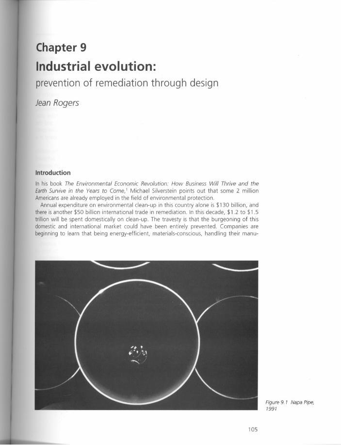
Chapter 9
Industrial evolution:
prevention of remediation through design
Jean Rogers
Introduction
In his book The Environmental Economic Revolution: How Business Will Thrive and the
Earth Survive in the Years to Come, 1 Michael Silverstein points out that some 2 millionAmericans are already employed in the field of environmental protection.
Annual expenditure on environmental clean-up in this country alone is $130 billion, andthere is another $50 billion international trade in remediation. In this decade, $1.2 to $1.5
trillion will be spent domestically on clean-up. The travesty is that the burgeoning of thisdomestic and international market could have been entirely prevented. Companies arebeginning to learn that being energy-efficient, materials-conscious, handling their manu-
105
Figure 9. 1 Napa Pipe,1991
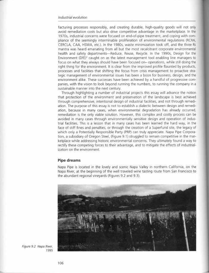
Figure 9.2 Napa River,1995
Industrial evolution
facturing processes responsibly, and creating durable, high-quality goods will not onlyavoid remediation costs but also drive competitive advantage in the marketplace. In the1970s, industrial concerns were focused on end-of-pipe treatment, and coping with compliance of the seemingly interminable proliferation of environmental regulations (RCRA,CERCLA, CM, HSWA, etc.). In the 1980s, waste minimization took off, and the three Rsmantra was heard emanating from all but the most recalcitrant corporate environmentalhealth and safety departments-Reduce, Reuse, Recycle. In the 1990s, Design for theEnvironment (DfE)2 caught on as the latest management tool enabling line managers tofocus on what they always should have been focused on- operations, while still doing theright thing for the environment. It is clear from the improved profile flaunted by products,processes and facilities that shifting the focus from crisis management to proactive strategic management of environmental issues has been a boon for business, design, and theenvironment alike. These successes have been achieved by a handful of progressive companies, with the vision to look beyond running the numbers, to running the company in asustainable manner into the next century.
Through highlighting a number of industrial projects this essay will advance the notionthat protection of the environment and preservation of the landscape is best achievedthrough comprehensive, intentional design of industrial facilities, and not through remediation. The purpose of this essay is not to establish a dialectic between design and remediation, because in many cases, when environmental degradation has already occurred,remediation is the only viable solution. However, this complex and costly process can beavoided in many cases through environmentally sensitive design and operation of industrial facilities. This is a lesson that in many cases has been learned the hard way, in theface of stiff fines and penalties, or through the creation of a Superfund site, the legacy ofwhich only a Potentially Responsible Party (PRP)can truly appreciate. Napa Pipe Corporation, a subsidiary of Oregon Steel, (Figure 9.1) struggled to remain competitive in the marketplace while addressing historic environmental concerns. They ultimately found a way torectify these competing forces to their advantage, and to mitigate the effects of industrialization on the environment.
Pipe dreams
Napa Pipe is located in the lovely and scenic Napa Valley in northern California, on theNapa River, at the beginning of the well traveled wine tasting route from San Francisco tothe abundant regional vineyards (Figures 9.2 and 9.3).
106
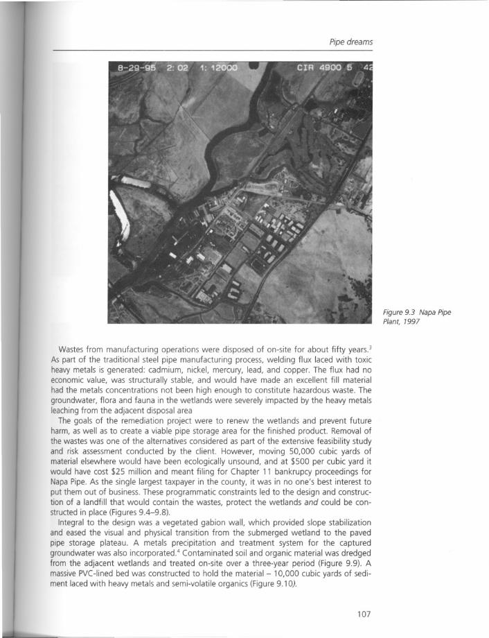
Pipe dreams
Figure 9.3 Napa PipePlant, 1997
Wastes from manufacturing operations were disposed of on-site for about fifty years.3
As part of the traditional steel pipe manufacturing process, welding flux laced with toxicheavy metals is generated: cadmium, nickel, mercury, lead, and copper. The flux had noeconomic value, was structurally stable, and would have made an excellent fill materialhad the metals concentrations not been high enough to constitute hazardous waste. Thegroundwater, flora and fauna in the wetlands were severely impacted by the heavy metalsleaching from the adjacent disposal area
The goals of the remediation project were to renew the wetlands and prevent futureharm, as well as to create a viable pipe storage area for the finished product. Removal ofthe wastes was one of the alternatives considered as part of the extensive feasibility studyand risk assessment conducted by the client. However, moving 50,000 cubic yards ofmaterial elsewhere would have been ecologically unsound, and at $500 per cubic yard itwould have cost $25 million and meant filing for Chapter 11 bankrupcy proceedings forNapa Pipe. As the single largest taxpayer in the county, it was in no one's best interest toput them out of business. These programmatic constraints led to the design and construction of a landfill that would contain the wastes, protect the wetlands and could be constructed in place (Figures 9.4-9.8).
Integral to the design was a vegetated gab ion wall, which provided slope stabilizationand eased the visual and physical transition from the submerged wetland to the pavedpipe storage plateau. A metals precipitation and treatment system for the capturedgroundwater was also incorporated.4 Contaminated soil and organic material was dredgedfrom the adjacent wetlands and treated on-site over a three-year period (Figure 9.9). Amassive PVC-lined bed was constructed to hold the material - 10,000 cubic yards of sediment laced with heavy metals and semi-volatile organics (Figure 9.10).
107
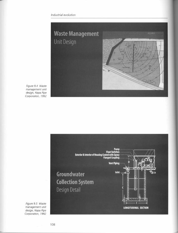
Figure 9.4 Wastemanagement unitdesign, Napa PipeCorporation, 1992
Figure 9.5 Waste
management unitdesign, Napa PipeCorporation, 1992
Industrial evolution
108
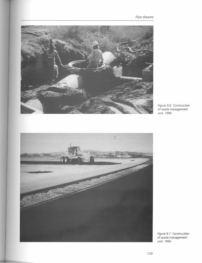
Pipe dreams
109
Figure 9.6 Construction
of waste managementunit, 1996
Figure 9.7 Construction
of waste managementunit, 1996
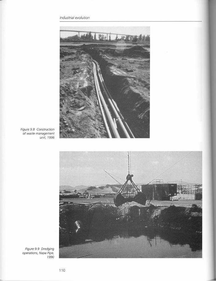
Figure 9.8 Construction
of waste managementunit, 1996
Figure 9.9 Dredgingoperations, Napa Pipe,
1990
Industrial evolution
110
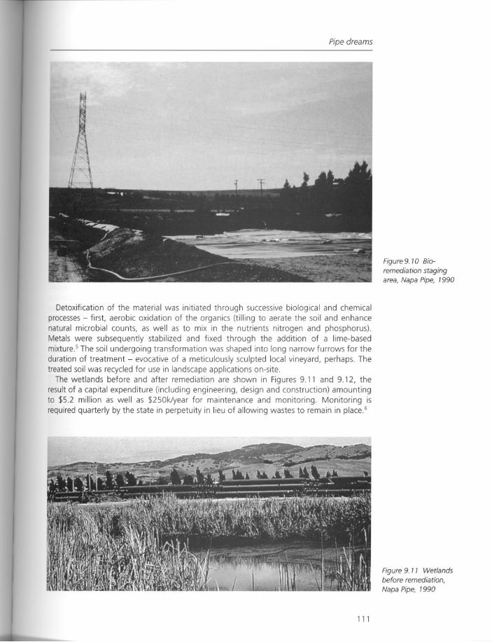
Pipe dreams
Detoxification of the material was initiated through successive biological and chemicalprocesses- first, aerobic oxidation of the organics (tilling to aerate the soil and enhancenatural microbial counts, as well as to mix in the nutrients nitrogen and phosphorus).Metals were subsequently stabilized and fixed through the addition of a lime-basedmixtureS The soil undergoing transformation was shaped into long narrow furrows for theduration of treatment - evocative of a meticulously sculpted local vineyard, perhaps. Thetreated soil was recycled for use in landscape applications on-site.
The wetlands before and after remediation are shown in Figures 9.11 and 9.12, theresult of a capital expenditure (including engineering, design and construction) amountingto $5.2 million as well as $250klyear for maintenance and monitoring. Monitoring isrequired quarterly by the state in perpetuity in lieu of allowing wastes to remain in place6
111
Figure 9. 10 Bioremediation stagingarea, Napa Pipe, 1990
Figure 9. 11 Wetlandsbefore remediation,
Napa Pipe, 1990
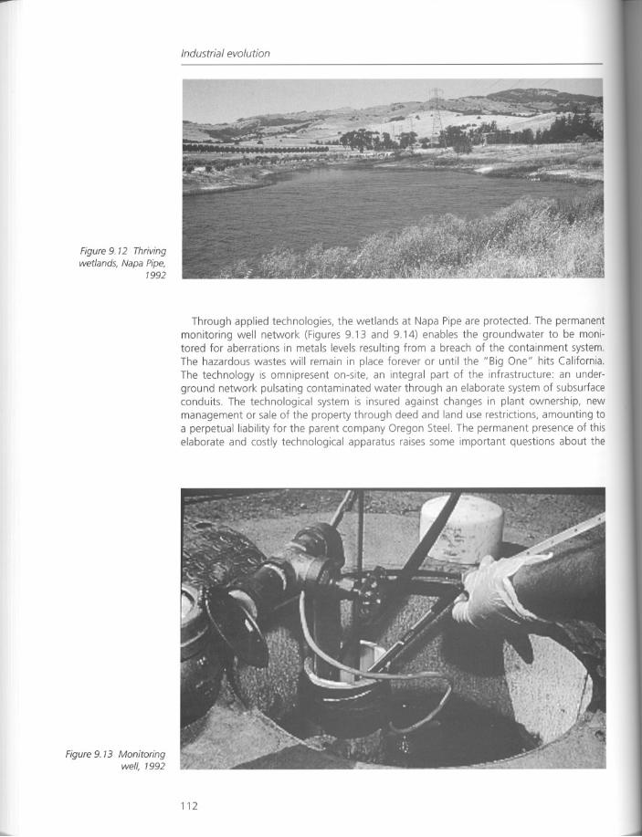
Figure 9. 12 Thrivingwetlands, Napa Pipe,
1992
Figure 9. 13 Monitoringwell, 1992
Industrial evolution
Through applied technologies, the wetlands at Napa Pipe are protected. The permanentmonitoring well network (Figures 9.13 and 9.14) enables the groundwater to be monitored for aberrations in metals levels resulting from a breach of the containment system.The hazardous wastes will remain in place forever or until the "Big One" hits CaliforniaThe technology is omnipresent on-site, an integral part of the infrastructure: an underground network pulsating contaminated water through an elaborate system of subsurfaceconduits. The technological system is insured against changes in plant ownership, newmanagement or sale of the property through deed and land use restrictions, amounting toa perpetual liability for the parent company Oregon Steel. The permanent presence of thiselaborate and costly technological apparatus raises some important questions about the
112
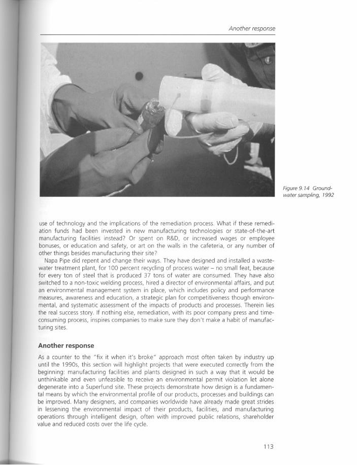
Another response
use of technology and the implications of the remediation process. What if these remediation funds had been invested in new manufacturing technologies or state-of-the-artmanufacturing facilities instead? Or spent on R&D, or increased wages or employeebonuses, or education and safety, or art on the walls in the cafeteria, or any number ofother things besides manufacturing their site?
Napa Pipe did repent and change their ways. They have designed and installed a wastewater treatment plant, for 100 percent recycling of process water - no small feat, becausefor every ton of steel that is produced 37 tons of water are consumed. They have alsoswitched to a non-toxic welding process, hired a director of environmental affairs, and putan environmental management system in place, which includes policy and performancemeasures, awareness and education, a strategic plan for competitiveness though environmental, and systematic assessment of the impacts of products and processes. Therein liesthe real success story. If nothing else, remediation, with its poor company press and timeconsuming process, inspires companies to make sure they don't make a habit of manufacturing sites.
Another response
As a counter to the "fix it when it's broke" approach most often taken by industry upuntil the 1990s, this section will highlight projects that were executed correctly from thebeginning: manufacturing facilities and plants designed in such a way that it would beunthinkable and even unfeasible to receive an environmental permit violation let alonedegenerate into a Superfund site. These projects demonstrate how design is a fundamental means by which the environmental profile of our products, processes and buildings canbe improved. Many designers, and companies worldwide have already made great stridesin lessening the environmental impact of their products, facilities, and manufacturingoperations through intelligent design, often with improved public relations, shareholdervalue and reduced costs over the life cycle.
113
Figure 9. 14 Groundwater sampling, 1992
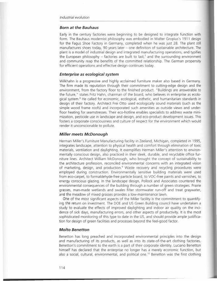
Industrial evolution
Born at the Bauhaus
Early in the century factories were beginning to be designed to integrate function withform. The Bauhaus modernist philosophy was embodied in Walter Gropius's 1911 designfor the Fagus Shoe Factory in Germany, completed when he was just 28. The plant stillmanufactures shoes today, 90 years later - one definition of sustainable architecture. Theplant is a model of industrial design and integrated manufacturing operations, and typifiesthe European philosophy - factories are built to lase and the surrounding environmentand community reap the benefits of the committed relationship. The German propensityfor efficient operations and effective design continues today.
Enterprise as ecological system
Wilkhahn is a progressive and highly acclaimed furniture maker also based in Germany.The firm made its reputation through their commitment to cutting-edge design and theenvironment, from the factory floor to the finished product. "Buildings are answerable tothe future," states Fritz Hahn, chairman of the board, who believes in enterprise as ecological system8 He called for economic, ecological, esthetic, and humanitarian standards indesign of their factory. Architect Frei Otto used ecologically sound materials (such as thesimple wood frame roofs) and incorporated such amenities as outside views and underfloor heating for seamstresses. Their eco-hotline enables specialists to address waste minimization, pesticide use in landscape and design, and eco-product development issues. Thisfosters a corporate consciousness and culture of respect for the environment which wouldrender it unconscionable to pollute.
Miller meets McDonough
Herman Miller's Furniture Manufacturing facility in Zeeland, Michigan, completed in 1995,integrates landscape, attention to physical health and comfort through elimination of toxicmaterials, ventilation and daylighting. It exemplifies Herman Miller's attention to environmentally conscious design, also practiced in their sleek, durable, and recyclable office furniture lines. Architect William McDonough, who brought the concept of sustainability tothe architecture profession, reconciled environmental concerns with an integrated visionof marketing, design, and production9 Waste recovery and recycling procedures wereemployed during construction. Environmentally sensitive building materials were usedfrom eco-carpet, to formaldehyde-free particle board, to VOC-free paints and varnishes, toenergy conscious glazing. In the landscape design, Pollock and Associates countered theenvironmental consequences of the building through a number of green strategies. Prairiegrasses, man-made wetlands and swales filter stormwater run-off and treat graywater,an~ the meadow of mixed grasses provides a low-maintenance lawn.
Ofje df the most significant aspects of the Miller facility is the commitment to quantifying tM€! return on investment. The DOE and US Green Building council have undertaken astudy to evaluate the effects of improved daylighting and indoor air quality on the incidence of sick days, manufacturing errors, and other aspects of productivity. It is the mostsophisticated monitoring of this type to date in the US, and should provide ample justification for design of green facilities and processes beyond the feel-good factor.
Molto Benetton
Benetton has long preached and incorporated environmental principles into the designand manufacturing of its products, as well as into its state-of-the-art clothing factories.Benetton's commitment to the earth is a part of their corporate identity. Luciano Benettonhimself has declared that the enterprise no longer has a merely economic function, butalso a social, cultural, environmental, and political one.IO Benetton was the first clothing
114
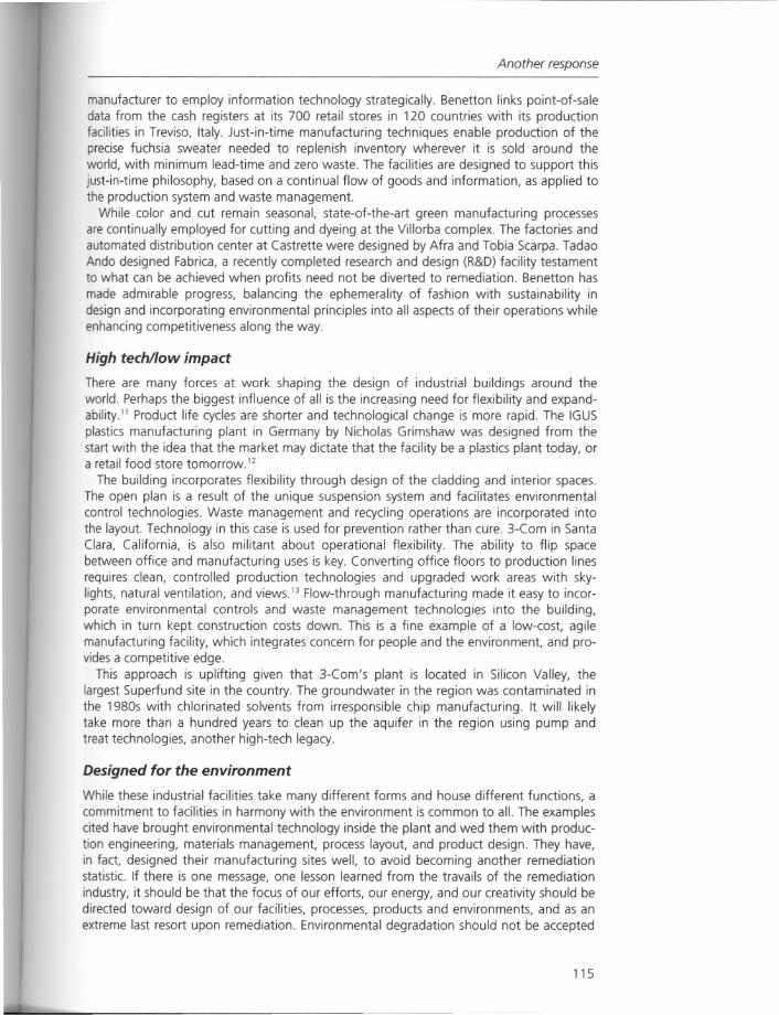
Another response
manufacturer to employ information technology strategically. Benetton links point-of-saledata from the cash registers at its 700 retail stores in 120 countries with its productionfacilities in Treviso, Italy. Just-in-time manufacturing techniques enable production of theprecise fuchsia sweater needed to replenish inventory wherever it is sold around theworld, with minimum lead-time and zero waste. The facilities are designed to support thisjust-in-time philosophy, based on a continual flow of goods and information, as applied tothe production system and waste management.
While color and cut remain seasonal, state-of-the-art green manufacturing processesare continually employed for cutting and dyeing at the Villorba complex. The factories andautomated distribution center at Castrette were designed by Afra and Tobia Scarpa. TadaoAndo designed Fabrica, a recently completed research and design (R&D) facility testamentto what can be achieved when profits need not be diverted to remediation. Benetton hasmade admirable progress, balancing the ephemerality of fashion with sustainability indesign and incorporating environmental principles into all aspects of their operations whileenhancing competitiveness along the way.
High tech/low impact
There are many forces at work shaping the design of industrial buildings around theworld. Perhaps the biggest influence of all is the increasing need for flexibility and expandability.'1 Product life cycles are shorter and technological change is more rapid. The IGUSplastics manufacturing plant in Germany by Nicholas Grimshaw was designed from thestart with the idea that the market may dictate that the facility be a plastics plant today, ora retail food store tomorrow. 12
The building incorporates flexibility through design of the cladding and interior spaces.The open plan is a result of the unique suspension system and facilitates environmentalcontrol technologies. Waste management and recycling operations are incorporated intothe layout. Technology in this case is used for prevention rather than cure. 3-Com in SantaClara, California, is also militant about operational flexibility. The ability to flip spacebetween office and manufacturing uses is key. Converting office floors to production linesrequires clean, controlled production technologies and upgraded work areas with skylights, natural ventilation, and views.13 Flow-through manufacturing made it easy to incorporate environmental controls and waste management technologies into the building,which in turn kept construction costs down. This is a fine example of a low-cost, agilemanufacturing facility, which integrates concern for people and the environment, and provides a competitive edge.
This approach is uplifting given that 3-Com's plant is located in Silicon Valley, thelargest Superfund site in the country. The groundwater in the region was contaminated inthe 1980s with chlorinated solvents from irresponsible chip manufacturing. It will likelytake more than a hundred years to clean up the aquifer in the region using pump andtreat technologies, another high-tech legacy.
Designed for the environment
While these industrial facilities take many different forms and house different functions, acommitment to facilities in harmony with the environment is common to all. The examplescited have brought environmental technology inside the plant and wed them with production engineering, materials management, process layout, and product design. They have,in fact, designed their manufacturing sites well, to avoid becoming another remediationstatistic. If there is one message, one lesson learned from the travails of the remediationindustry, it should be that the focus of our efforts, our energy, and our creativity should bedirected toward design of our facilities, processes, products and environments, and as anextreme last resort upon remediation. Environmental degradation should not be accepted
115
Figure 9. 15 Drill rig,1995
Figure 9. 16 Trees, 1995
Industrial evolution
as a given. The uncontrolled release of toxic materials from our factories and landfills isnot a new and exciting challenge to be incorporated into the design of the landscape. It isa far greater challenge to eliminate revealed and concealed impacts on the environmententirely. Designers are in the unique position of being able to eliminate environmentalimpacts from the start. This means considering the environmental implications at everystage of design, just as program, site, context, function, form, technology and material areconsidered. Involved are the hard decisions that designers face every day, such as facilitysiting and reuse options, building envelope design, energy considerations, materials selection, integration with operations, and, most importantly, communicating the design visionto management (Figures 9.15 and 9.16).
As we celebrate sites which have been manufactured in this compendium of essays, letit not be forgotten that we should be intelligently designing our manufacturing sites tobegin with:
• Factories which are integrated with the location and site, and do not put at risk eitherthe workers, community or the environment.
116
Notes
• Factories which conserve energy and resources, where water is appreciated as a precious resource not to be wasted in processes or landscape design.
• Facilities which account for the hazardous nature of materials handled and the toxicityof products produced, and expose piping above grade for ease of maintenance andprevention of unnoticed leaks into soil or groundwater.
• Plants which provide natural light and views and breed a sense of pride in the workplace.
• Facilities which understand human fallibility, and provide reassurance and insurance intheir process design.
• Facilities in which technology is directed toward prevention rather than to the controlof environmental impacts.
The examples cited all include one similar component from inception - respect for theenvironment. They were conceived as total ecological manufacturing sites - a symbol ofan elusive industrial ideal in which work and well being, technology and conservation ofthe environment are finally linked. It is in this spirit that our sites are best manufactured. Itwill take nothing short of an industrial evolution.
Notes
Silverstein, Michael, The Environmental Economic Revolution: How Business will Thrive and the
Earth Survive in the Years to Come (London: St. Martin's Press, 1993).
2 Rogers, Jean, "Design for Environment: Design Management Practices and Opportunities from
Diagnostic to Design" (San Francisco, Calif.: Deloitte and Touche, 1997). This methodology
assesses the environmental impacts of facilities and products during the planning and design
phases. The framework is intended as a guide for design managers to incorporate environmental
principles into design without sacrificing esthetics, function, or cost.
3 Montgomery Watson, Site Investigation/Feasibility Study for Napa Pipe Corporation (Walnut
Creek, Calif.: Montgomery Watson, 1990).
4 Montgomery Watson, Waste Management Unit Design - Napa Pipe Corporation (Walnut Creek,
Calif.: Montgomery Watson, 1992).
5 Montgomery Watson, Treatability Study for Bioremediation - Napa Pipe Corporation (Walnut
Creek, Calif.: Montgomery Watson, 1991).
6 Montgomery Watson, Quarterly Monitoring Report for Napa Pipe Corporation (Walnut Creek,
Calif.: Montgomery Watson, 1993).
7 Gordon, Barclay F., "The Fagus Factory: Contemporary Design Seventy Years Later." Architectural
Record 169 (9) (New York: McGraw-Hili, 1981), pp 114-17.
8 Brozen, Kenneth, "Wilkhahn's Direction as a Design Leader," Interiors 148 (6) (New York: Bill
board Publications, 1989), pp. 120-3.
9 "Herman Miller," Architectural Record Vol. 12 (New York: McGraw-Hili, 1996), pp. 28-33.
10 Zardina, Mirko, "Benetton," Lotus International no. 85 (Milan, Italy: Elemond, S.pA, 1995),
pp.101-21.
11 "Industrious Architecture," World Architecture no. 54 (London: Cheerman, Ltd, 1997),
pp. 119-25.
12 Mark Bryden, "Factory with Flexibility Built In - The IGUS Plant," The Architects' Journal 197 (12)
(London: emap Business Publishing, 1997), pp. 33-44.
13 "Manufacturing Collaboration - 3-Com," Architectural Record 12 (New York: McGraw-Hili,
1996), pp 23-39
117

Industrial evolution
Further reading
Barnett, Dianna and Browning, William (1995) A Primer on Sustainable Building, Snowmass, Colorado:Rocky Mountain Institute.
Crosbie, Michael J. (1995) Green Architecture, Rockport, Mass.: Rockport Publishers.Mackenzie, Dorothy (1997) Green Design, London: Laurence King Publishing.
Pilatowicz, Grazyna (1995) Eco-Interiors, a Guide to Environmentally Conscious Interior Design. NewYork: John Wiley & Sons.
US Green Building Council (1996) Sustainable Building Technical Manual, Denver: Public Technology,Inc.
Zeiher, Laura (1996) The Ecology of Architecture, New York: Whitney Library of Design, BPI Communications.
118
Response
Response
Re-manufactured sites?
Through several case studies, Dr Rogers offers a relatively simple but important observation. With the focus during the last several decades on the remediation of past contamination caused by industrial operations, Dr Rogers redirects our attention toward the future.Shesuggests that by considering the design of industrial and manufacturing facilities to beself-contained systems we may be able to prevent a repetition of this industrial legacy ofenvironmental degradation. Dr Rogers suggests that this redesign includes the eliminationof toxic materials during construction and on-site mechanical or biological treatment ofcontaminated by-products to eliminate their migration off-site.
This focus toward the design of future facilities is important, and Dr Rogers' rationalethat environmentally sound practices are a "boon for business, design and the environment alike" has strong merits. Dr Rogers also demonstrates through the case studies thatan evolving environmental ethic is transforming the design of many workplace environments. To offer a fair overview when discussing the operational and philosophical shiftbrought about during the 1980s and 1990s, one must also consider that many industrieshave chosen to relocate their operations to countries offering low wages and little in theway of environmental restrictions. Examples abound in Mexico, India and the Far East ofindustries dumping lethal toxins into the surrounding soil and waterways. From a globalperspective, a discussion of industrial reform cannot just focus on the innovative, environmentally conscious European and American industries. They offer a valid representation ofan economically viable restructuring from dirty to clean operations. But if the growth ofindustrial pollution is not to be spread along with production to other parts of the world,this model of clean design will need wider acceptance to compete. If proved economicallyviable, such a model would negate the perceived tension between economic growth andenvironmental protection in Third World countries. Critical to the validation of this modelis economic analysis and further documentation. Until that time firms that implement environmentally sound design and operations need acknowledgement and support, andstrict regulations will continue to play a powerful role in maintaining environmentalperformance levels for designers and operators. If other countries had equally strongstandards the option of relocating and continuing damaging practices would be eliminated as an option, and we might well see more innovative designs to meet uniformstandards for industrial development
In her paper, Dr Rogers makes a compelling argument that the price of remediation represents a direct increase to the cost of doing business, reducing the competitive edge formany industries. This argument would be strengthened if several examples with substantiated data were offered. Historically, wastes have been dumped with little regard for thelong-term environmental impact, usually because it was the least expensive option. Thearea of cost comparisons is critical since proven economic analysis would offer strongincentives for a transformation in the design of industrial facilities and their operations.
There are several design implications to this integrative approach as suggested by DrRogers, including the planning of integrated cleansing and responsible material handlingsystems early in the programming stages of site development. What may be mostprovocative for designers, and not dissimilar to the design philosophy offered by Peter Latzin Chapter 11, is Dr Rogers' view that "technology is omnipresent on-site, an integral partof the infrastructure ... " While different in some respects from the approach of PeterLatz, who preserves and readapts the industrial structures of the past, she does offer asimilar vision through the integration of technology and natural systems. The resulting
119
Industrial evolution
design implication will be the integration of artificial technologies with natural systems totreat the contaminated by-products. This dialectic offers provocative relationships anddesign challenges in which the esthetics of nature and industry may coexist.
Dr Rogers offers several case studies as examples of "green" buildings, worker-friendlyenvironments, and a reduced use of toxic materials in the building design. However, inmost industrial production, such as chemical manufacturing facilities, energy conversionplants or materials fabrication shops, the processes will still produce toxins as by-products.How in the future will designers and planners respond to these new site issues? Oneanswer is that they already are responding. As environmental standards have becomestricter, several changes such as on-site detention and retention of stormwater and liquidwaste products must now be incorporated into the site planning. Subsurface collectionsystems, containment barriers and gas release systems are now found in both new sitesand in older industrial sites being redeveloped. Maybe more interesting and certainly morespeculative is how some of the technologies discussed in several of the papers offer newsystems that will have design implications when planning for potentially hazardous conditions. For example, there are situations where designers might integrate phytomediation systems into the facility design for the treatment of spoils, see Chapter 4 forEric Carman's" From Laboratory to Landscape." Will there be opportunities to create successionary forests, forests that are implemented sequentially as the spoils are amassed onsite? (See Chapter 13) Can bio-filtration be used to cleanse the wastewater on-site toreclaim the water for reuse in the operation? (See Chapter 12) It becomes clear, as it hasin many of the papers, that an integrated planning team must be initiated early in thedesign process so that treatment options are considered to address on-site problemsbefore remediation is required.
As was pointed out by McNeil and Lange in the essay in Chapter 6, "Engineering UrbanBrownfield Development," historically industry has been tied to the urban sectors of thiscountry. Today, with increasing "clean industries," including computer chip processingplants and high tech manufacturing, and the switch from railroad to air and trucking forproduct distribution, this historic tie to the city may be broken. Today many industries arerelocating to rural and suburban locations. With this relocation, industries have greaterquantities of surrounding land, land that can be designed for and used as on-site cleaningsystems to detoxify waste products. The increased space offers the possibility to createlarge-scale wetlands and containment systems for storage of contaminated materials. Thecounterpoint is that so many of our lands have already been degraded, and the move torural areas where land is relatively pristine to create new industries is a net loss of environmental quality. Would it not make better sense to clean up the old sites and recycle themfor" clean industry"? Are there ways that industry can be rebuilt within our urban centers,utilizing whole systems design, or are the land parcels too small to integrate biologicalcleansing systems? As Dr Rogers points out, building recycling for readaptive uses,accountability of waste generation and recycling during building construction, plus sustainable landscape measures, are all important considerations when developing a newfacility. The real legacy with which we are struggling today is the result of the inadequatedisposal of toxic waste products, water and soil contamination from discharges and leakages, and airborne contamination from plant emissions. The greater question may behow, as we anticipate these occurrences, we can mediate them with systems that treat inplace or contain toxins on-site for long-term treatment in a safe and sustainable manner.In addition to on-site measures Dr Rogers offers examples of both low-tech and high-techsolutions for responsible production. In the example of the Benetton corporation, usingcomputer monitoring to link product need to availability reduced production, and thelong-term storage on-site of potentially toxic materials became unnecessary. This relativelysimple example indicates how efficiency of production design may reduce over-producedproduct disposal, with the energy consumption used for unnecessary production thus
120

Note
being eliminated. As one surveys the diverse range of technical and designed solutions forremediation presented in this book, it seems logical that through a forvvard thinkingmodel these systems could be integrated during the development of industrial facilitiesand designed into the master planning, creating closed regenerative operations in which"enterprise [is an] ecological system." 1
Note
Brazen, Kenneth, "Wilkhahn's Direction as a Design Leader," Interiors 148 (6) (New York: BillboardPublications, 1989, pp. 120-3).
Part III
Reclaimed landscapes
Part III comprises seven essays, six of which have supporting responses, that focus ondesign approaches to the reclamation of manufactured sites, including the research andapplication of advanced landscape technologies such as bioengineering, waste encapsulation methods and innovative ground-surface finishes.
The transformation of these sites involves decisions of what is to remain and what is to
be removed - the importation, recycling or removal of site material, structures and utilities.Projects of national and international significance demonstrate the design influences onreclaimed landscapes, alongside descriptions of the conceptual design processes and theireventual development through to built work.
A broad introductory essay by landscape architect Rebecca Krinke places this work inboth a historical and contemporary framework. The essay features case study projects of anumber of contributors to this book presented in a recent exhibition at the HarvardGraduate School of Design. Krinke describes and analyzes these projects as celebratingand revealing past land uses through the clean-up strategies that were undertaken in theirregeneration. Differing scales of manufactured sites and time periods over which workwas carried out, and stormwater management and clean-up, are demonstrated in thelarge-scale reclamation of the nO-hectare Tyssen Steel works in Duisburg, Germany bylandscape architect Peter Latz (Latz + Partner). By contrast, the Federal Medical Centerproject and the Robert Harbor Tidal Marsh, at 0.25 of an acre in size, presented by bioengineer Wendi Goldsmith (The Bioengineering Group, Inc.), demonstrates an innovativenew approach to the management of stormwater and site design proposals that integrateresource restoration with site planning.
William Young, a landscape architect formerly employed by the Department of Sanitation in New York, explains research, field testing and site design strategies developed onthe Fresh Kills landfill restoration in Staten Island. This involves the integration of cappingtechnologies, revegetation strategies, and habitat creation allied to landfill reclamation.Questions relating to what constitutes the correct restoration strategies for the landfill areraised. Kirt Rieder, a landscape architect, continues on this topic for the landscape reclamation project at Crissy Field, San Francisco, by raising and questioning "the issue of balancing current use with a proposed reuse of the site driven by historic precedent."
Finally, two essays explore differing aspects of the "Green Games" - the Olympic 2000infrastructure and open space structure for Sydney, Australia. Michael Horne discussesexamples of the integration of innovative construction technologies and design strategiesand the initial research and development that was undertaken. Finally a detailed discussion

Reclaimed landscapes
on the open space structure focuses on the Northern Water Feature. Kevin Conger's essayexplores the use of new technologies to innovate and express natural processes in conjunction with creative engineering and infrastructure. Together they demonstrate the viability of large-scale civic design projects to integrate and demonstrate science, engineeringand design innovation from regional strategies down to the detailed site scale.
124
Chapter 10
Overview:design practice and manufactured sites
Rebecca Krinke
Introduction
The projects in the "Manufactured Sites" exhibition highlight the role that technologies,employed to address a legacy of environmental degradation, have contributed to the builtform of a newly designed landscape. Designers are increasingly asked to work on landwith decades of environmental damage, oftentimes with multiple sources of contamination. Many potential development sites are within cities, where even though the land mayhave environmental problems, its location may make it too valuable to ignore. Environmental policies may dictate that remediation take place, and funding may be available toaddress the site's reuse. New paradigms of landscape types with their own environmentalissues,such as landfills or military bases, may suggest new design solutions.
The case studies that are discussed in this chapter are located in the United States,Germany or Australia. The West is on the leading edge of remediating landscapes,although it is becoming a worldwide phenomenon. Western nations industrialized earlierand more relentlessly than other parts of the world, and differing forms of legislation haverecently been enacted to address this environmental degradation.
The environmental legacy of the Industrial Revolution
The development of a more efficient steam engine in 1769, and the need to mine coal toprovide fuel for it, were pivotal in launching the Industrial Revolution. Extracting and combusting coal poses severe environmental problems. Deep mines may acidify streams, andsurface mines are difficult to be reclaimed for anything other than pastures (Hayes 2000:29). Burning coal releases toxins into the atmosphere and produces acid rains that destroyimmense areas of forests worldwide. The destruction of forests adversely affects airquality; plants cleanse the air of carbon dioxide and produce the earth's oxygen.
Oil and natural gas are the other carbon-based fuels that power industry. Oil spillage isa huge problem - not just the dramatic spills from ocean-going oil tankers, but the day-today spills and leaks from service stations and individual cars that account for millions ofadditional tons of oil polluting the water and soil. Natural gas burns cleaner than both coaland oil, but does release carbon dioxide into the air (Hayes 2000: 31). The nuclear powerindustry produces radioactive wastes that will not degrade to harmless levels for thousands of years.
Mining degrades the landscape in multiple ways. Extracting a desired metal from rock
125
Overview
leaves behind vast piles of tailings (the excess material that did not contain the minerals),and the extraction process itself has its own environmental issues. For example, the goldmining industry has developed a technique that uses cyanide to extract gold from the ore.
Industrialization, including that of agricultural practices, has led to water and soil contaminated with chemicals. Contaminated soil and water introduce toxins into the web of
plant and animal life. Pesticides in the groundwater means that sources of human drinkingwater are affected. Agriculture and other human development of the land have drainedmillions of acres of American wetlands. Wetlands are key to flood storage, erosion control,and the natural filtration of pollutants.
The earth's human inhabitants generate vast amounts of garbage, and disposing of thiswaste has become increasingly problematic. Western nations produce most of the world'sgarbage, and have most of the environmental restrictions on its disposal. In the recentpast, garbage was often shipped to developing nations, promising environmental problems for the future of these countries. In the United States, most garbage ends up in landfills, although some of the nation's waste is recycled. If improperly constructed ordamaged, contaminants can leach from landfills into adjacent soil and water.
The Industrial Revolution changed the human relationship with the earth. As the worldmoved from agriculture to industry, a mechanistic view of the universe began to supplantthe idea of an organic nature. A desire for" progress" and faith in technology implied thatthe earth was a place to extract resources and its "complementary" idea: that the earthcould absorb anything humankind asked of it. Land was typically viewed as a commodity,and in general this idea has prevailed until quite recently. It was in the 1960s when theenvironmental movement questioned the idea that the industrialized nations could continue with their same habits of production and consumption. The earth, water and skieswere becoming visibly polluted. The first American environmental laws, such as the CleanAir Act of 1963, were passed. In 1970, the first Earth Day was held, and millions of citizens demonstrated their concern for the health of the planet.
The legacy of the Industrial Revolution - its disruption of the natural systems of air,water, soil, and habitat - is being addressed in the twenty-first century. Mandated byregulations, but also reflecting a change in society's values, despoiled sites are beingreclaimed, and the "Manufactured Sites" case studies reveal this paradigm shift.
Design goals, theory and practice
Recovering a despoiled site involves the variables of the particular site (its problems andthe program for its reuse), legal requirements that may have to be met, as well as thevision of the designer. The final design and form of the recovered landscape may be thevisual and ecological integration of the project site into the landscape that surrounds it.This occurs primarily when the site has been damaged and the recovery restores thehealthy functioning of the ecosystem.
Another approach is to recover the landscape with the intention of clearly revealing thehand of the designer, underscoring human intervention on the site. The site's history maybe disclosed clearly or subtly alluded to, but restoring the landscape to a (perhapsunknown) "natural" appearance is not a goal of many of today's designers. Artist RobertSmithson's "earthworks" and their engagement of natural (including human) processes,and architect Peter Eisenman's idea of the site as a "palimpsest," have informed many ofthe" Manufactured Sites" projects.
It should be noted that the selection of Smithson and Eisenman does not mean to implythat these two individuals are the only operative influences on the case studies. Both ofthese theorists/artists were influenced by the written and built work of others. Smithsonwas part of the New York art world in the 1960s and 1970s and interacted with manygroundbreaking artists and collectors. He was a voracious reader, with interests ranging
126
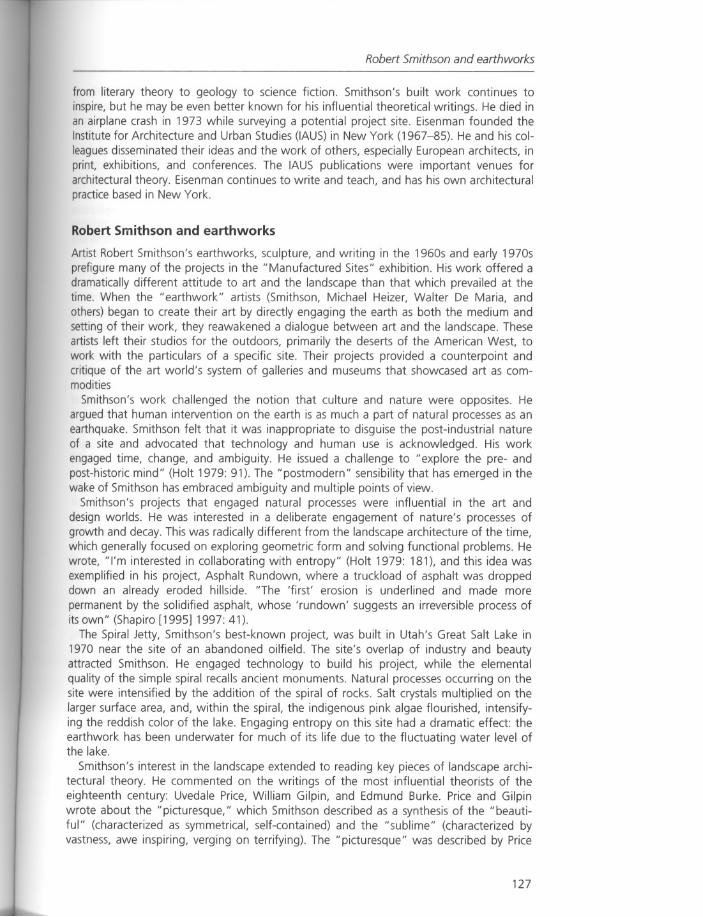
Robert Smithson and earthworks
from literary theory to geology to science fiction. Smithson's built work continues toinspire, but he may be even better known for his influential theoretical writings. He died inan airplane crash in 1973 while surveying a potential project site. Eisenman founded theInstitute for Architecture and Urban Studies (IAUS) in New York (1967-85). He and his colleagues disseminated their ideas and the work of others, especially European architects, inprint, exhibitions, and conferences. The IAUS publications were important venues forarchitectural theory. Eisenman continues to write and teach, and has his own architecturalpractice based in New York.
Robert Smithson and earthworks
Artist Robert Smithson's earthworks, sculpture, and writing in the 1960s and early 1970sprefigure many of the projects in the "Manufactured Sites" exhibition. His work offered adramatically different attitude to art and the landscape than that which prevailed at thetime. When the "earthwork" artists (Smithson, Michael Heizer, Walter De Maria, andothers) began to create their art by directly engaging the earth as both the medium andsetting of their work, they reawakened a dialogue between art and the landscape. Theseartists left their studios for the outdoors, primarily the deserts of the American West, towork with the particulars of a specific site. Their projects provided a counterpoint andcritique of the art world's system of galleries and museums that showcased art as commodities
Smithson's work challenged the notion that culture and nature were opposites. Heargued that human intervention on the earth is as much a part of natural processes as anearthquake. Smithson felt that it was inappropriate to disguise the post-industrial natureof a site and advocated that technology and human use is acknowledged. His workengaged time, change, and ambiguity. He issued a challenge to "explore the pre- andpost-historic mind" (Holt 1979: 91). The "postmodern" sensibility that has emerged in thewake of Smithson has embraced ambiguity and multiple points of view.
Smithson's projects that engaged natural processes were influential in the art anddesign worlds. He was interested in a deliberate engagement of nature's processes ofgrowth and decay. This was radically different from the landscape architecture of the time,which generally focused on exploring geometric form and solving functional problems. Hewrote, "I'm interested in collaborating with entropy" (Holt 1979: 181), and this idea wasexemplified in his project, Asphalt Rundown, where a truckload of asphalt was droppeddown an already eroded hillside. "The 'first' erosion is underlined and made morepermanent by the solidified asphalt, whose 'rundown' suggests an irreversible process ofits own" (Shapiro [1995] 1997: 41).
The Spiral Jetty, Smithson's best-known project was built in Utah's Great Salt Lake in1970 near the site of an abandoned oilfield. The site's overlap of industry and beautyattracted Smithson. He engaged technology to build his project, while the elementalquality of the simple spiral recalls ancient monuments. Natural processes occurring on thesite were intensified by the addition of the spiral of rocks. Salt crystals multiplied on thelarger surface area, and, within the spiral, the indigenous pink algae flourished, intensifying the reddish color of the lake. Engaging entropy on this site had a dramatic effect: theearthwork has been underwater for much of its life due to the fluctuating water level ofthe lake.
Smithson's interest in the landscape extended to reading key pieces of landscape architectural theory. He commented on the writings of the most influential theorists of theeighteenth century: Uvedale Price, William Gilpin, and Edmund Burke. Price and Gilpinwrote about the "picturesque," which Smithson described as a synthesis of the "beautiful" (characterized as symmetrical, self-contained) and the "sublime" (characterized byvastness, awe inspiring, verging on terrifying). The "picturesque" was described by Price
127
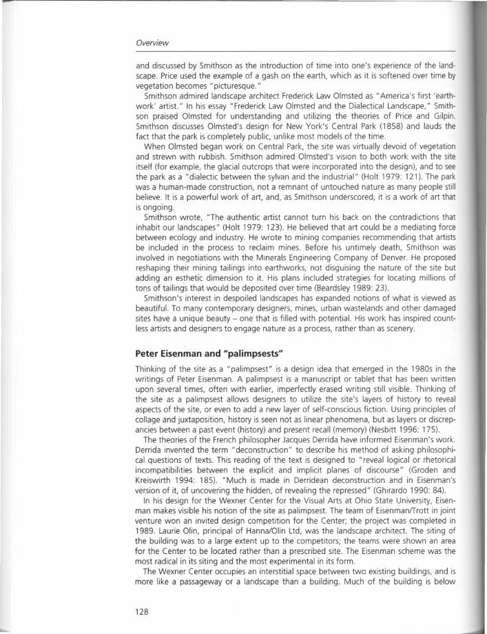
Overview
and discussed by Smithson as the introduction of time into one's experience of the landscape. Price used the example of a gash on the earth, which as it is softened over time byvegetation becomes "picturesque."
Smithson admired landscape architect Frederick Law Olmsted as "America's first 'earthwork' artist." In his essay "Frederick Law Olmsted and the Dialectical Landscape," Smithson praised Olmsted for understanding and utilizing the theories of Price and Gilpin.Smithson discusses Olmsted's design for New York's Central Park (1858) and lauds thefact that the park is completely public, unlike most models of the time.
When Olmsted began work on Central Park, the site was virtually devoid of vegetationand strewn with rubbish. Smithson admired Olmsted's vision to both work with the site
itself (for example, the glacial outcrops that were incorporated into the design), and to seethe park as a "dialectic between the sylvan and the industrial" (Holt 1979: 121). The parkwas a human-made construction, not a remnant of untouched nature as many people stillbelieve. It is a powerful work of art, and, as Smithson underscored, it is a work of art thatis ongoing.
Smithson wrote, "The authentic artist cannot turn his back on the contradictions thatinhabit our landscapes" (Holt 1979: 123). He believed that art could be a mediating forcebetween ecology and industry. He wrote to mining companies recommending that artistsbe included in the process to reclaim mines. Before his untimely death, Smithson wasinvolved in negotiations with the Minerals Engineering Company of Denver. He proposedreshaping their mining tailings into earthworks, not disguising the nature of the site butadding an esthetic dimension to it. His plans included strategies for locating millions oftons of tailing's that would be deposited over time (Beardsley 1989: 23).
Smithson's interest in despoiled landscapes has expanded notions of what is viewed asbeautiful. To many contemporary designers, mines, urban wastelands and other damagedsites have a unique beauty - one that is filled with potential. His work has inspired countless artists and designers to engage nature as a process, rather than as scenery.
Peter Eisenman and "palimpsests"
Thinking of the site as a "palimpsest" is a design idea that emerged in the 1980s in thewritings of Peter Eisenman. A palimpsest is a manuscript or tablet that has been writtenupon several times, often with earlier, imperfectly erased writing still visible. Thinking ofthe site as a palimpsest allows designers to utilize the site's layers of history to revealaspects of the site, or even to add a new layer of self-conscious fiction. Using principles ofcollage and juxtaposition, history is seen not as linear phenomena, but as layers or discrepancies between a past event (history) and present recall (memory) (Nesbitt 1996: 175).
The theories of the French philosopher Jacques Derrida have informed Eisenman's work.Derrida invented the term" deconstruction" to describe his method of asking philosophical questions of texts. This reading of the text is designed to "reveal logical or rhetoricalincompatibilities between the explicit and implicit planes of discourse" (Groden andKreiswirth 1994: 185). "Much is made in Derridean deconstruction and in Eisenman'sversion of it, of uncovering the hidden, of revealing the repressed" (Ghirardo 1990: 84).
In his design for the Wexner Center for the Visual Arts at Ohio State University, Eisenman makes visible his notion of the site as palimpsest. The team of EisenmanlTrott in jointventure won an invited design competition for the Center; the project was completed in1989. Laurie Olin, principal of Hanna/Olin Ltd, was the landscape architect. The siting ofthe building was to a large extent up to the competitors; the teams were shown an areafor the Center to be located rather than a prescribed site. The Eisenman scheme was themost radical in its siting and the most experimental in its form.
The Wexner Center occupies an interstitial space between two existing buildings, and ismore like a passageway or a landscape than a building. Much of the building is below
128
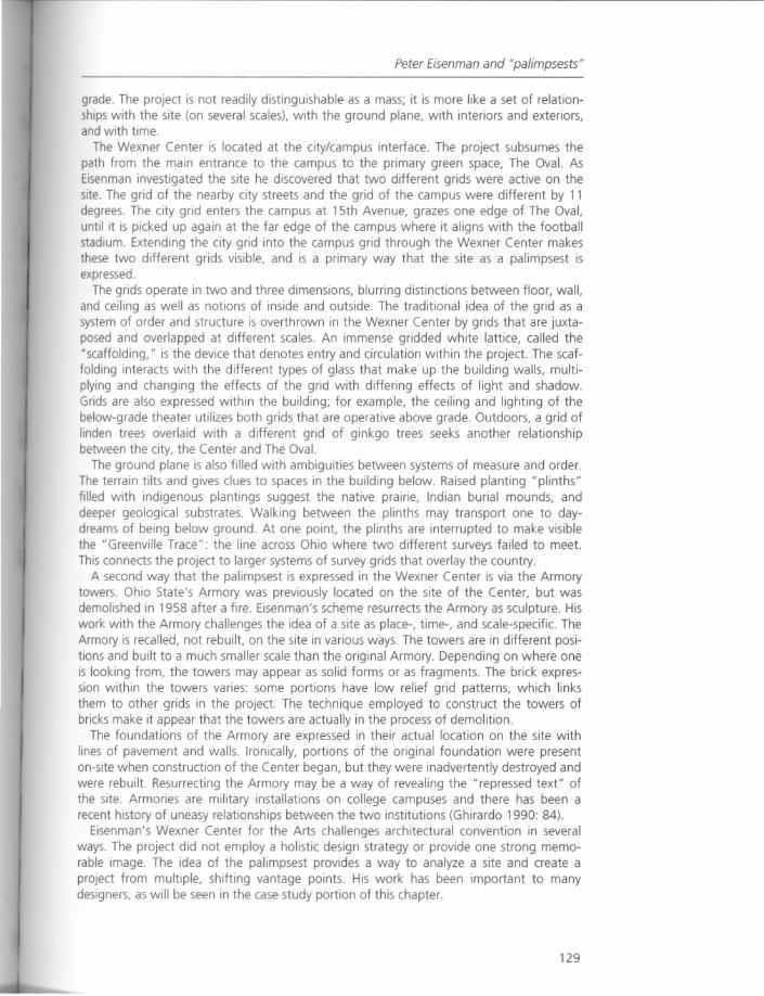
Peter Eisenman and "palimpsests"
grade. The project is not readily distinguishable as a mass; it is more like a set of relationships with the site (on several scales), with the ground plane, with interiors and exteriors,and with time.
The Wexner Center is located at the city/campus interface. The project subsumes thepath from the main entrance to the campus to the primary green space, The Oval. AsEisenman investigated the site he discovered that two different grids were active on thesite. The grid of the nearby city streets and the grid of the campus were different by 11degrees. The city grid enters the campus at 15th Avenue, grazes one edge of The Oval,until it is picked up again at the far edge of the campus where it aligns with the footballstadium. Extending the city grid into the campus grid through the Wexner Center makesthese two different grids visible, and is a primary way that the site as a palimpsest isexpressed.
The grids operate in two and three dimensions, blurring distinctions between floor, wall,and ceiling as well as notions of inside and outside. The traditional idea of the grid as asystem of order and structure is overthrown in the Wexner Center by grids that are juxtaposed and overlapped at different scales. An immense gridded white lattice, called the"scaffolding," is the device that denotes entry and circulation within the project. The scaffolding interacts with the different types of glass that make up the building walls, multiplying and changing the effects of the grid with differing effects of light and shadow.Grids are also expressed within the building; for example, the ceiling and lighting of thebelow-grade theater utilizes both grids that are operative above grade. Outdoors, a grid oflinden trees overlaid with a different grid of ginkgo trees seeks another relationshipbetween the city, the Center and The Oval.
The ground plane is also filled with ambiguities between systems of measure and order.The terrain tilts and gives clues to spaces in the building below. Raised planting "plinths"filled with indigenous plantings suggest the native prairie, Indian burial mounds, anddeeper geological substrates. Walking between the plinths may transport one to daydreams of being below ground. At one point, the plinths are interrupted to make visiblethe "Greenville Trace": the line across Ohio where two different surveys failed to meet.This connects the project to larger systems of survey grids that overlay the country.
A second way that the palimpsest is expressed in the Wexner Center is via the Armorytowers. Ohio State's Armory was previously located on the site of the Center, but wasdemolished in 1958 after a fire. Eisenman's scheme resurrects the Armory as sculpture. Hiswork with the Armory challenges the idea of a site as place-, time-, and scale-specific. TheArmory is recalled, not rebuilt, on the site in various ways. The towers are in different positions and built to a much smaller scale than the original Armory. Depending on where oneis looking from, the towers may appear as solid forms or as fragments. The brick expression within the towers varies: some portions have low relief grid patterns, which linksthem to other grids in the project. The technique employed to construct the towers ofbricks make it appear that the towers are actually in the process of demolition.
The foundations of the Armory are expressed in their actual location on the site withlines of pavement and walls. Ironically, portions of the original foundation were presenton-site when construction of the Center began, but they were inadvertently destroyed andwere rebuilt. Resurrecting the Armory may be a way of revealing the "repressed text" ofthe site. Armories are military installations on college campuses and there has been arecent history of uneasy relationships between the two institutions (Ghirardo 1990: 84).
Eisenman's Wexner Center for the Arts challenges architectural convention in severalways. The project did not employ a holistic design strategy or provide one strong memorable image. The idea of the palimpsest provides a way to analyze a site and create aproject from multiple, shifting vantage points. His work has been important to manydesigners, as will be seen in the case study portion of this chapter.
129
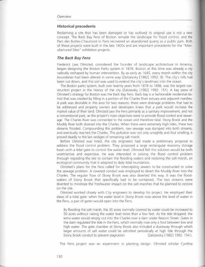
Overview
Historical precedents
Reclaiming a site that has been damaged or has outlived its original use is not a newconcept. The Back Bay Fens of Boston remade the landscape for flood control, and theParc des Buttes-Chaumont in Paris recovered an abandoned quarry as a public park. Bothof these projects were built in the late 1800s and are important precedents for the" Manufactured Sites" exhibition projects.
The Back Bay Fens
Frederick Law Olmsted, considered the founder of landscape architecture in America,began designing the Boston Parks system in 1878. Boston at this time was already a cityradically reshaped by human intervention. By as early as 1645, every marsh within the cityboundaries had been altered in some way (Zaitzevsky [1982] 1992: 9). The city's hills hadbeen cut down, and this soil was used to extend the city's landmass into the ocean.
The Boston parks system, built over twenty years from 1878 to 1898, was the largest construction project in the history of the city (Zaitzevsky [1982] 1992: 151). A key piece ofOlmsted's strategy for Boston was the Back Bay Fens. Back Bay is a fashionable residential district that was created by filling in a portion of the Charles River estuary and adjacent marshes.A park was desirable in this area for two reasons: there were drainage problems that had tobe addressed and property owners and developers knew that a park would increase themarket value of their land. Olmsted saw the Fens primarily as a sanitary improvement, and nota conventional park, as the project's main objectives were to provide flood control and sewerage. The Charles River was connected to the ocean and therefore tidal. Stony Brook and theMuddy River both drained into the Charles. When there were extremely high tides, these twostreams flooded. Compounding this problem, raw sewage was dumped into both streams,and eventually reached the Charles. This pollution was not only unsightly and foul smelling, itproved deadly to the last vestiges of remaining salt marsh.
Before Olmsted was hired, the city engineers had made a preliminary proposal toaddress the flood control problem. They proposed a large rectangular masonry storagebasin with a tidal gate to control the water level. Olmsted felt this solution would be bothunattractive and expensive. He was interested in solving the flood control problemthrough regrading the site to contain the flooding waters and restoring the salt marsh, anecological community that is adapted to daily tidal inundation.
Olmsted's plans for the Fens called for intercepting sewers to be constructed to solvethe sewage problem. A covered conduit was employed to divert the Muddy River into theCharles. The regular flow of Stony Brook was also diverted this way. It was the floodwaters of Stony Brook that specifically had to be contained. The two streams werediverted to minimize the freshwater impact on the salt marshes that he planned to restoreon the site.
Olmsted worked closely with City engineers to develop his project. He employed theirideas of a tidal gate: when the water level in Stony Brook rose above the level of water inthe Fens, a pair of gates would open into the Fens.
By flooding the salt marsh, the 30 acres normally covered by water could be increased to50 acres without raising the water level more than a few feet. As the tide dropped, theextra water would empty out into the Charles over a dam under Beacon Street. Gates inthe dam regulated the tide in the Fens,which normally rose only a foot between low andhigh water. The gate chamber at Stony Brook also included a sluiceway through whichlarger amounts of salt water could be admitted periodically at high tide through theStony Brook conduit to prevent stagnation (Zaitzevsky [1982] 1992: 154).
The Fens project was an experiment in planting design. Olmsted scholar Cynthia
130
Historical precedents
Zaitzevsky notes, "This choice [restoring salt marshes on the Fens site] committed him to aplanting program so innovative that it literally had no precedent" (Zaitzevsky [1982] 1992:186). Olmsted's restoration differed from a naturally occurring salt marsh in several ways.A salt marsh found in nature would have mud banks exposed during periods of low tide.The water level in the marsh that Olmsted designed would fluctuate by only one foot,thereby decreasing the appearance of bare slopes. Naturally occurring salt marshescontain plant communities that are associated with specific water levels and their associated salt content. In Olmsted's salt marsh design, with its smaller vertical change in tidalfluctuation, his planting palette could be both more condensed and more extensive thanwould occur in nature (Zaitzevsky [1982] 1992: 186).
As Olmsted wrote:
A mere imitation of nature, however successful, is not art, and the purpose to imitatenature, or to produce an effect which shall seem to be natural and interesting, is notsufficient for the duty before us. A scene in nature is made up of various parts; eachpart has its individual character and its possible ideal. It is unlikely that accidentshould bring together the best possible ideals of each separate part ... and it is stillmore unlikely that accident should group a number of these possible ideals in such away that not only one or two but that all should be harmoniously related one to theother. It is evident, however, that an attempt to accomplish this artificially is notimpossible ... The result would be a work of art ...
(Sutton [1971]1997: 15)
The transitional areas of groundcovers and shrubs were selected for their salt tolerance.Only where the Fens met the city edge was there an edge of turf with street trees.Olmsted wanted visitors to the Fens to think that the city had simply grown up around themarsh. He wrote that the effect of this would be "novel," but also that the salt marsh
would possibly be found more poetic for "town-weary minds than an elaborate andelegant garden-like work" (Zaitzevsky [1982] 1992: 57).
Today, the salt marshes are gone from the Fens. With the Charles River Dam's construction in 1910, the Charles is no longer tidal. Olmsted's office made a proposal to redesignthe Fens to function without salt water, but nothing was done, and in fact, as a freshwater corridor, the Fens became heavily polluted with trash.
Olmsted titled his design for the Fens a "Sanitary Improvement or the Back Bay DrainageBasins," rather than a park. He emphasized that the design solution was to provide floodcontrol and sewerage, which in turn increased public health benefits. This concept links hiswork to one of the reasons that "manufactured sites" need to be reclaimed today: they areplaces of public health concern. As in many contemporary projects, Olmsted completelyremade the site: the Back Bay Fenswas created by extensive filling and dredging. The earthwork that he designed to contain floodwaters was a marriage of esthetics and function thatprefigures much of the design work discussed in this chapter.
Pare des Buttes-Chaumont
In Parc des Buttes-Chaumont, completed in Paris in 1867, quarries that became dumpswere recovered as a highly artificial public park. As Paris grew, this industrial waste siteoriginally on the outskirts of the city was too important to be neglected. In the nineteenthcentury, parks had become public. They were seen as important contributors to the physical and social development of citizens, and as a way to showcase cultural achievements.The opening of Parc des Buttes-Chaumont was planned to coincide with the 1867 WorldExposition, Napoleon Ill's celebration of French innovation in industry and the arts (Meyer1991: 19).
131
Overview
Parc des Buttes-Chaumont was designed by J.c. Adolphe Alphand; trained as a civilengineer he designed many parks, squares and boulevards in Paris in the late 1800s.Echoing the philosophy of Olmsted, Alphand believed that the garden was a work of artand should not attempt to copy nature. He too was interested in a conversation betweenthe human-made and the organic. In Parc des Buttes-Chaumont, Alphand embraced thechallenges of an oddly shaped parcel of degraded land crossed by a railway line. His parkis a masterful work that unites art and engineering.
The park's infrastructure and other functional requirements were viewed by Alphand asopportunities. He wrote:
Through the artifice of embankments and landscaping, one may even gain advantagefrom a big road or railway running alongside or through a park. If the work is welldone, the trains, carriages and pedestrians which seem to circulate within it, give adegree of animation, and the talent of the designer transforms what seems to be anirredeemable fault into positive ornament ... One can also turn the view of a station,and industrial building or any construction to advantage, providing that it is fittinglyframed in the landscape.
(Vernes 1984: 60, fn.)
The site's unusual, almost violent topography was exploited in Alphand's design. Hemade the central spire of rock larger and capped it with a temple, where a stairwaydescends to the water or to a dizzying suspension bridge. Quarry walls were reshaped,and the remaining topography was regraded for a smooth and grassy contrast to therocky focal points. The site's topography and the park's paths were united by a synthesisof esthetics and function. Alphand's objective was to link focal points, such as parkentrances and buildings, via a consistent curve (never with straight or serpentine lines).This strategy provides a fluid, changing view for the pedestrian and the best fit to theevenly shaped contours.
The park provides a fascinating contrast between highlighting actual geology and themanufacture of an artificial geology. Sophisticated engineering technologies wereemployed to create an artificial lake and waterfalls. An innovative application of concrete,was employed to produce artificial rocks. The fabricated geology extended to creatingconcrete stalactites and stalagmites in the underground cavern. Throughout the park, thefantasy continues with concrete steps and rails made in the form of logs.
The artificiality of the park makes it a theatrical space of exploration and promenade.Louis Aragon, a key member of the Surrealist movement in art, wrote about a nighttimevisit to Parc des Buttes-Chaumont in his 1926 book Paris Peasant:
The Buttes-Chaumont stirred a mirage in us, one with all the tangibility of these phenomena, a shared mirage over which we all felt we had the same hold ... At last wewere going to destroy boredom, a miraculous hunt opened up before us, a field ofexperiment where it was unthinkable that we should not receive countless surprisesand who knows? a great revelation that might transform life and destiny.
(Aragon [1926] 1994: 133)
The Parc des Buttes-Chaumont was created from a site scarred by industrial processes.Alphand exploited the quarrying of the site in his design; the history of the site was nothidden. Geology both real and artificial was celebrated. Employing the technologicalprocesses and materials of the time, he created a park with layers of real (and invented)natural and cultural history. Alphand's Parc des Buttes-Chaumont provides an examplefrom the nineteenth century of the site as a palimpsest.
132
Introduction to the case studies
Introduction to the case studies
The projects that are described below were all featured in the "Manufactured Sites" exhibition. When the projects have addressed similar issues, such as restoring a marsh, theyhave been grouped for comparative purposes.
Restoration
Saw Mill Creek Salt Marsh Restoration, New York
CrissyField, San Francisco, CaliforniaThe Saw Mill Creek Salt Marsh Restoration and the Crissy Field project both involved thecreation of salt (tidal) marshes, although for different reasons and to different effects. TheSaw Mill Creek Salt Marsh project utilized restoration and bioengineering to repair theeffects of a toxic oil spill. At Crissy Field (which is under construction at the time ofwriting) a salt marsh is being created where one once was. The designers' goal at CrissyField is not to restore the marshes to their original configuration, but rather to create amarsh that makes it very apparent that these marshes are the work of human intervention.
In the Saw Mill Creek project a disastrous oil spill devastated the existing salt marshes.The priority in this project was restore the marsh, and another goal was to assesswhetherthe reintroduction of Spartina alterniflora (salt marsh cord grass) could reduce total petroleum hydrocarbon (TPH) levels in the soil. Crissy Field, a National Park Service project,asked the designers, Hargreaves Associates, to recreate the salt marshes that once existedon the site as part of their design. A re-creation of a historic airfield was also mandated.These two requirements for the park showcase compelling issues of what historical perioda site should be restored to and how restoration goals that may compete historically canbe resolved - i.e., how would two things that existed in the same location, but at differenttimes, both be restored?
The Saw Mill Creek project was necessitated by a 1990 oil spill of over half a millionbarrels of fuel oil into the Arthur Kill, a tidal strait separating the western shore of StatenIsland from New Jersey. While tidal marshes were once viewed as swampy wastelands,they are now known to be critical for facilitating the ecological processes of habitat creation, water filtration, and erosion control. The oil spill destroyed birds, fish, and smalleranimals, as well as hundreds of acres of low marsh vegetation consisting primarily ofSpartina alterniflora. Exxon was found legally responsible for the spill and, through thedamages awarded, the City of New York created a Salt Marsh Restoration Team withintheir Natural Resources Group (Marton 1998: 84).
The effects of fuel oil on salt marshes have been documented since the 1970s, but no
attempt had been made to restore vegetation to areas impacted by oil. The efforts alongthe Arthur Kill therefore represent an experiment that has implications beyond the scopeof the January 1990 spill and subsequent restoration. The technology to restore the marshwas extremely simple, but laborious: hundreds of thousands of plugs of Spartina alterniflora have been planted by hand. Hundreds of volunteers collected more than six millionseeds, replanted them in nurseries, then transplanted the shoots to the marsh. The addition of one ounce, time-release fertilizer to each plug proved indispensable in achievingthe goals of oxygenating the cord grass root zone as well as the beneficial bacteria foundin the root zone. This bacteria uses carbon in the fuel oil for its own growth, degradingthe oil and bringing down the level of total petroleum hydrocarbons in the process. Onaverage, fertilized plants were more than twice as likely to survive (Marton 1998: 87).
This project highlights the need for restoration (in cases like the Arthur Kill oil spill) intwo key ways: areas that were not replanted have not been naturally recolonized by cordgrass, and the replanted areas now have lower concentrations of oil than areas that
133
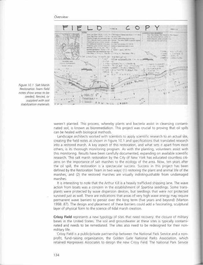
Overview
rlE
..
p yc. 0LD, LU'SIIllcrlir.';"[~
""•• '"'•.••_IML\\ I "'i. ..,••.a~_Slal," 'ft.'!. P1••••F•••••:..f'_.F,bn\I..,,~. ra..-.
'4dn H'CofIW_·•.111'.•. · • 50".. • •••••• bIrv. -.J "-_,.,du.s,..n ..••M•••.•.••)vl _.odu8ld~ •••••.•••• WIII6Imon •••• ~(tIl ••••". J -..ltaIlIp .•._ ••.••PMII1 ~"r -.I .__......•....._Pol •• 1011"" It ""'7 .• o-n ..., ~" •••••.•..•aw-...... _ ..,...-d. 11lllJ1•• "' ••••.•
s"ool,."IwlI<1llIlWlliCl'v.lllID_pta... c\(od-Tidlr •• I1••••• S MI.'"
T~I' ~I._t." -.lMd1l.hanftd ••••• I_vl •• ,,'\~lui&I '•••• (1"" ••• FIll ••• ~
~~;P'I-...l •• :1 "'-"""ilODtPUie-.tPl '''''OUobol.at1eol_ . ..b
"•• Man, •• SlJoq ft. fobor81. A" ''' ••• tt ~ ••••.• 'kt t
11)t~'~
~& 0" f 0 "'"
..-' .
Figure 10. 1 Salt MarshRestoration Team field
notes show areas to be
seeded, fenced, or
supplied with soilstabilization materials
weren't planted. This process, whereby plants and bacteria assist in cleansing contaminated soil, is known as bioremediation. This project was crucial to proving that oil spillscan be healed with biological methods.
Landscape architects worked with scientists to apply scientific research to an actual site,creating the field notes as shown in Figure 10.1 and specifications that translated researchinto a restored marsh. A key aspect of this restoration, and what sets it apart from mostothers, is its thorough monitoring program. As with the planting, volunteers assist withthis monitoring. Results have been carefully documented, expanding on available scientificresearch. This salt marsh restoration by the City of New York has educated countless citizens on the importance of salt marshes to the ecology of the area. Now, ten years afterthe oil spill, the restoration is a spectacular success. Success in this project has beendefined by the Restoration Team in two ways: (1) restoring the plant and animal life of themarshes, and (2) the restored marshes are visually indistinguishable from undamagedmarshes.
It is interesting to note that the Arthur Kill is a heavily trafficked shipping lane. The waveaction from boats was a concern in the establishment of Spartina seedlings. Some transplants were protected by wave dispersion devices, but seedlings that were not protectedsurvived just as well. There are indications that areas of very high wave energy may requirepermanent wave barriers to persist over the long term (five years and beyond) (Marton1998: 87). The design and placement of these barriers could add a fascinating, sculpturallayer of physical form to the science of tidal marsh creation.
Crissy Field represents a new typology of sites that need recovery: the closure of militarybases in the United States. The soil and groundwater at these sites is typically contaminated and needs to be remediated. The sites also need to be redesigned for their nonmilitary life.
Crissy Field is a public/private partnership between the National Park Service and a nonprofit, fund-raising organization, the Golden Gate National Parks Association, whichretained Hargreaves Associates to design the new Crissy Field. The National Park Service
134
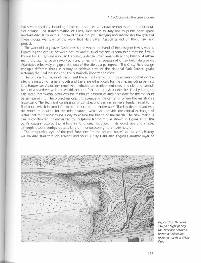
Introduction to the case studies
has several sections, including a cultural resources, a natural resources and an interpretative division The transformation of Crissy Field from military use to public open spaceinvolved discussion with all three of these groups. Clarifying and reconciling the goals ofthese groups was part of the work that Hargreaves Associates did on the Crissy Fieldproject.
The work of Hargreaves Associates is one where the hand of the designer is very visible.Expressing the overlay between natural and cultural systems is something that the firm isknown for. Crissy Field is in San Francisco, a dense urban area with a long history of settlement; the site has been reworked many times. In the redesign of Crissy Field, HargreavesAssociates effectively engaged the idea of the site as a palimpsest. The Crissy Field designengages different times in history to achieve both of the National Park Service goals:restoring the tidal marshes and the historically important airfield.
The original 180 acres of marsh and the airfield cannot both be accommodated on thesite: it is simply not large enough and there are other goals for the site, including parkinglots. Hargreaves Associates employed hydrologists, marine engineers, and planting consultants to assist them with the establishment of the salt marsh on the site. The hydrologistscalculated that twenty acres was the minimum amount of area necessary for the marsh tobe self-sustaining. The project restores this acreage in the center of where the marsh washistorically. The technical constraints of constructing the marsh were fundamental to itsfinal form, which in turn influenced the form of the entire park. The key determinant wasthe optimum location for the tidal channel, which will provide the critical exchange ofwater that must occur twice a day to ensure the health of the marsh. The new marsh isclearly constructed, characterized by sculptural landforms, as shown in Figure 10.2. Thepark's design restores the airfield in its original location, in its exact size and shape,although it too is configured as a landform, underscoring its remade nature.
The interpretive layer of the park functions "in the present tense" as the site's historywill be discussed through exhibits and tours. Crissy Field also engages another layer of
135
Figure 10.2 Detail ofsite plan highlightingthe interface betweenrestored airfield and
restored marsh at CrissyField
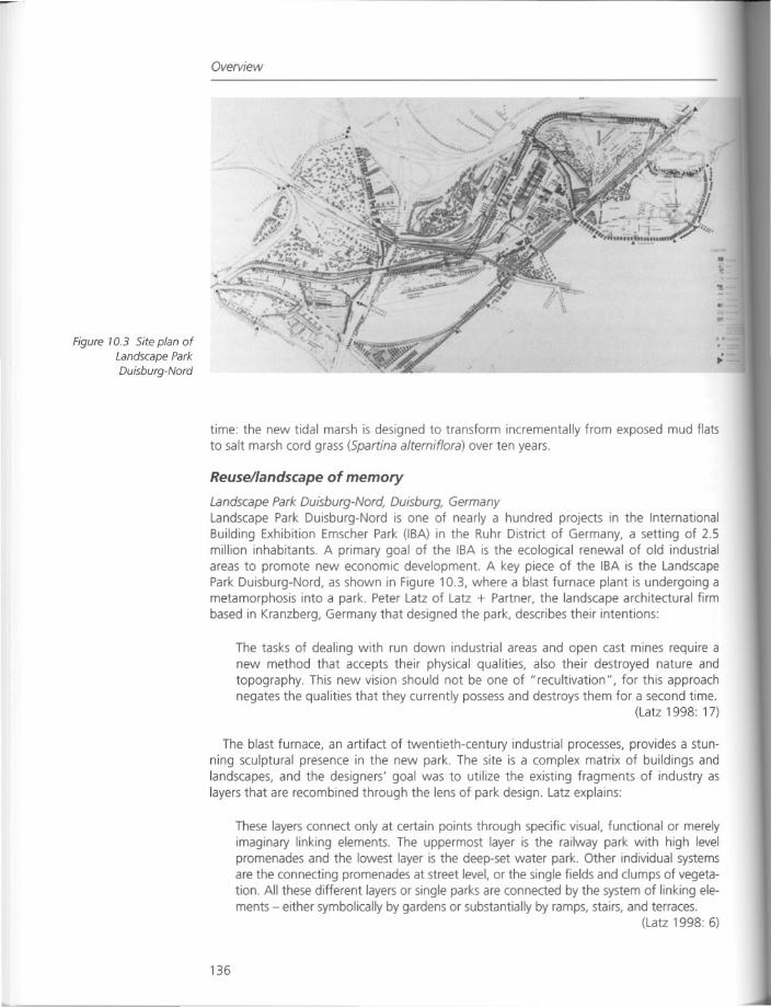
Figure 70.3 Site plan ofLandscape ParkDuisburg-Nord
Overview
•
..
time: the new tidal marsh is designed to transform incrementally from exposed mud flatsto salt marsh cord grass (Spartina alterniflora) over ten years.
Reuse/landscape of memory
Landscape Park Duisburg-Nord, Duisburg, GermanyLandscape Park Duisburg-Nord is one of nearly a hundred projects in the InternationalBuilding Exhibition Emscher Park (IBA) in the Ruhr District of Germany, a setting of 2.5million inhabitants. A primary goal of the IBA is the ecological renewal of old industrialareas to promote new economic development. A key piece of the IBA is the LandscapePark Duisburg-Nord, as shown in Figure 10.3, where a blast furnace plant is undergoing ametamorphosis into a park. Peter Latz of Latz + Partner, the landscape architectural firmbased in Kranzberg, Germany that designed the park, describes their intentions:
The tasks of dealing with run down industrial areas and open cast mines require anew method that accepts their physical qualities, also their destroyed nature andtopography. This new vision should not be one of "recultivation", for this approachnegates the qualities that they currently possess and destroys them for a second time.
(Latz 1998: 17)
The blast furnace, an artifact of twentieth-century industrial processes, provides a stunning sculptural presence in the new park. The site is a complex matrix of buildings andlandscapes, and the designers' goal was to utilize the existing fragments of industry aslayers that are recombined through the lens of park design. Latz explains:
These layers connect only at certain points through specific visual, functional or merelyimaginary linking elements. The uppermost layer is the railway park with high levelpromenades and the lowest layer is the deep-set water park. Other individual systemsare the connecting promenades at street level, or the single fields and clumps of vegetation. All these different layers or single parks are connected by the system of linking elements - either symbolically by gardens or substantially by ramps, stairs, and terraces.
(Latz 1998: 6)
136
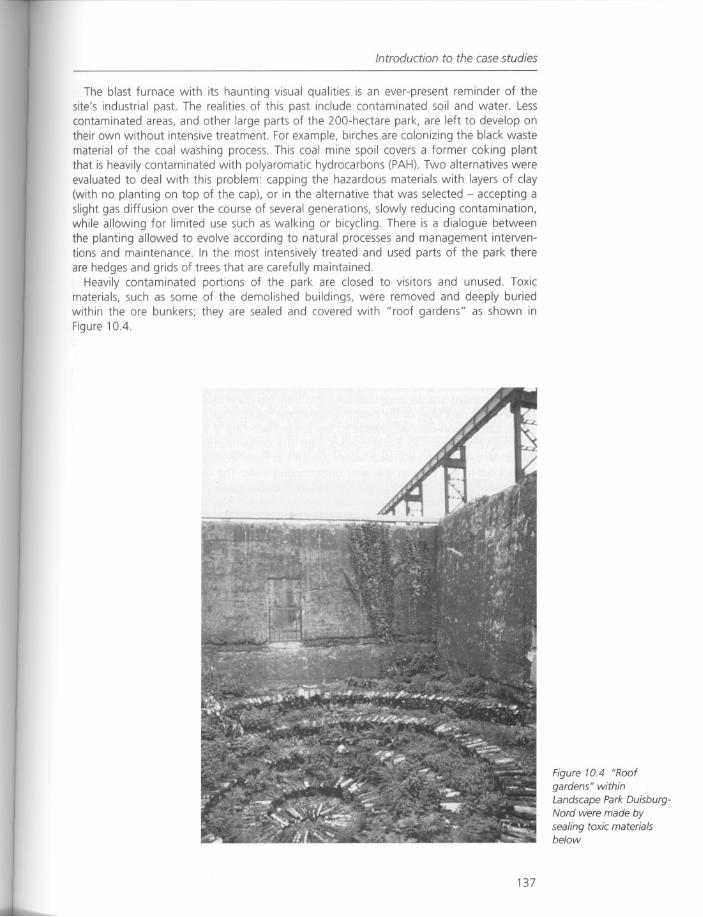
Introduction to the case studies
The blast furnace with its haunting visual qualities is an ever-present reminder of thesite's industrial past The realities of this past include contaminated soil and water. Lesscontaminated areas, and other large parts of the 200-hectare park, are left to develop ontheir own without intensive treatment For example, birches are colonizing the black wastematerial of the coal washing process. This coal mine spoil covers a former coking plantthat is heavily contaminated with polyaromatic hydrocarbons (PAH). Two alternatives wereevaluated to deal with this problem: capping the hazardous materials with layers of clay(with no planting on top of the cap), or in the alternative that was selected - accepting aslight gas diffusion over the course of several generations, slowly reducing contamination,while allowing for limited use such as walking or bicycling. There is a dialogue betweenthe planting allowed to evolve according to natural processes and management interventions and maintenance. In the most intensively treated and used parts of the park thereare hedges and grids of trees that are carefully maintained.
Heavily contaminated portions of the park are closed to visitors and unused. Toxicmaterials, such as some of the demolished buildings, were removed and deeply buriedwithin the ore bunkers; they are sealed and covered with "roof gardens" as shown inFigure 10.4.
137
Figure 10.4 "Roof
gardens" withinLandscape Park DuisburgNord were made bysealing toxic materialsbelow
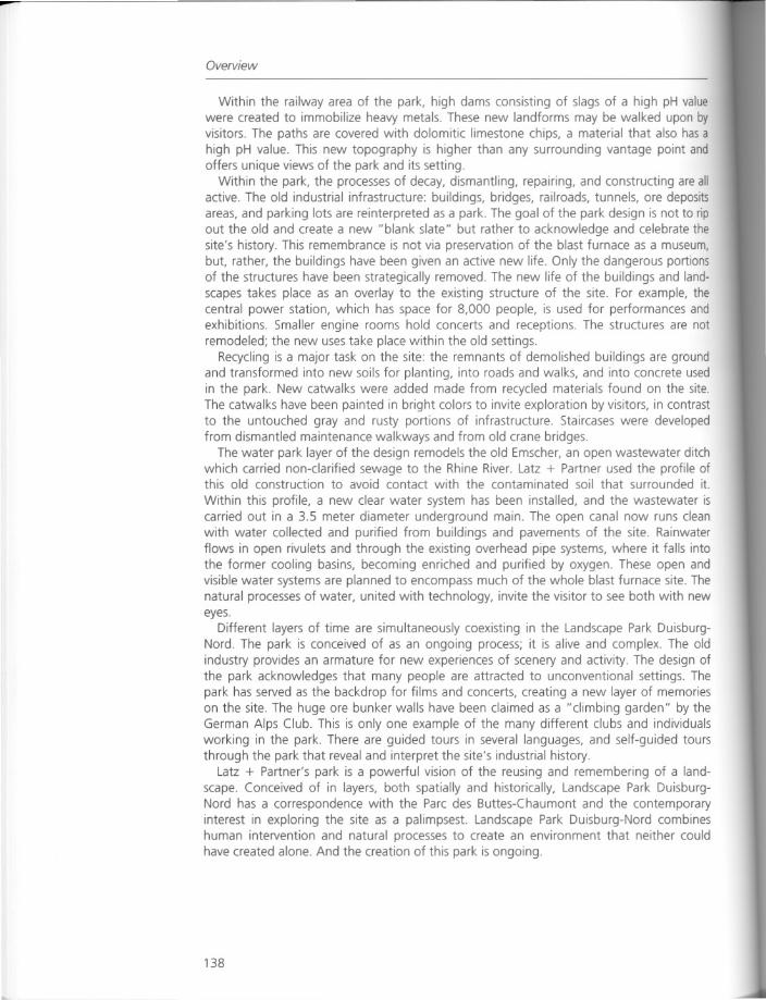
Overview
Within the railway area of the park, high dams consisting of slags of a high pH valuewere created to immobilize heavy metals. These new landforms may be walked upon by
visitors. The paths are covered with dolomitic limestone chips, a material that also has ahigh pH value. This new topography is higher than any surrounding vantage point andoffers unique views of the park and its setting.
Within the park, the processes of decay, dismantling, repairing, and constructing are allactive. The old industrial infrastructure: buildings, bridges, railroads, tunnels, ore depositsareas, and parking lots are reinterpreted as a park. The goal of the park design is not to ripout the old and create a new "blank slate" but rather to acknowledge and celebrate thesite's history. This remembrance is not via preservation of the blast furnace as a museum,but, rather, the buildings have been given an active new life. Only the dangerous portionsof the structures have been strategically removed. The new life of the buildings and landscapes takes place as an overlay to the existing structure of the site. For example, thecentral power station, which has space for 8,000 people, is used for performances andexhibitions. Smaller engine rooms hold concerts and receptions. The structures are notremodeled; the new uses take place within the old settings.
Recycling is a major task on the site: the remnants of demolished buildings are groundand transformed into new soils for planting, into roads and walks, and into concrete usedin the park. New catwalks were added made from recycled materials found on the site.The catwalks have been painted in bright colors to invite exploration by visitors, in contrastto the untouched gray and rusty portions of infrastructure. Staircases were developedfrom dismantled maintenance walkways and from old crane bridges.
The water park layer of the design remodels the old Emscher, an open wastewater ditchwhich carried non-clarified sewage to the Rhine River. Latz + Partner used the profile ofthis old construction to avoid contact with the contaminated soil that surrounded it.
Within this profile, a new clear water system has been installed, and the wastewater iscarried out in a 3.5 meter diameter underground main. The open canal now runs cleanwith water collected and purified from buildings and pavements of the site. Rainwaterflows in open rivulets and through the existing overhead pipe systems, where it falls intothe former cooling basins, becoming enriched and purified by oxygen. These open andvisible water systems are planned to encompass much of the whole blast furnace site. Thenatural processes of water, united with technology, invite the visitor to see both with neweyes.
Different layers of time are simultaneously coexisting in the Landscape Park DuisburgNord. The park is conceived of as an ongoing process; it is alive and complex. The oldindustry provides an armature for new experiences of scenery and activity. The design ofthe park acknowledges that many people are attracted to unconventional settings. Thepark has served as the backdrop for films and concerts, creating a new layer of memorieson the site. The huge ore bunker walls have been claimed as a "climbing garden" by theGerman Alps Club. This is only one example of the many different clubs and individualsworking in the park. There are guided tours in several languages, and self-guided toursthrough the park that reveal and interpret the site's industrial history.
Latz + Partner's park is a powerful vision of the reusing and remembering of a landscape. Conceived of in layers, both spatially and historically, Landscape Park DuisburgNord has a correspondence with the Parc des Buttes-Chaumont and the contemporaryinterest in exploring the site as a palimpsest. Landscape Park Duisburg-Nord combineshuman intervention and natural processes to create an environment that neither couldhave created alone. And the creation of this park is ongoing.
138
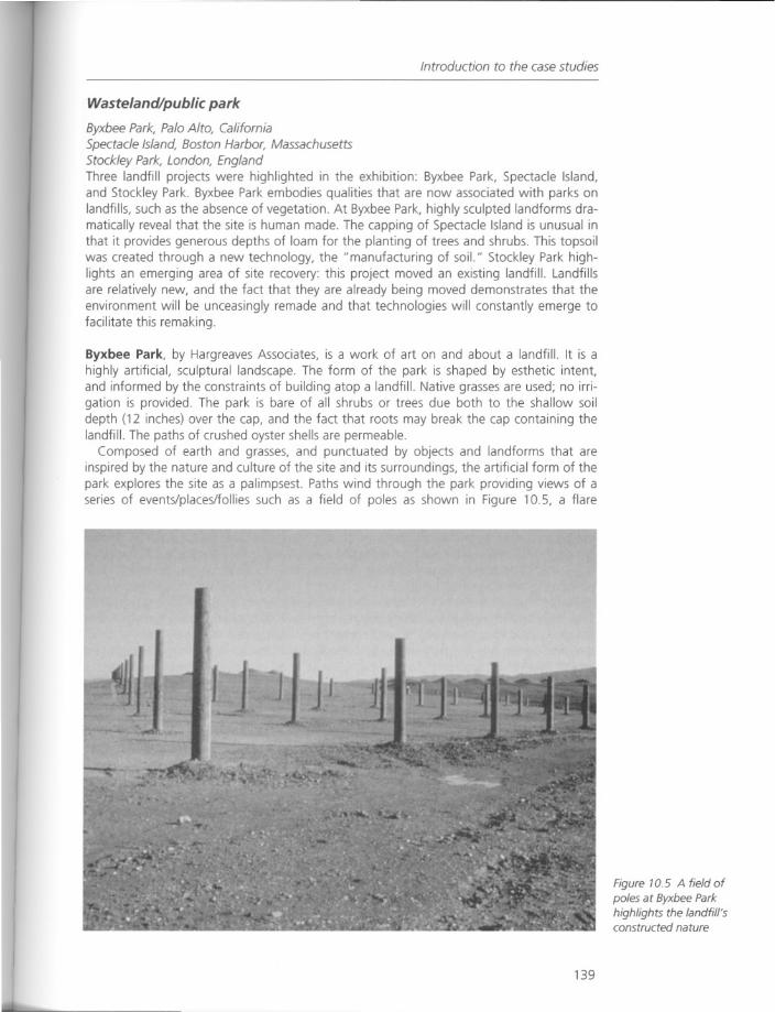
Introduction to the case studies
Wasteland/public park
Byxbee Park, Palo Alto, CaliforniaSpectacle Island, Boston Harbor, MassachusettsStockley Park, London, EnglandThree landfill projects were highlighted in the exhibition: Byxbee Park, Spectacle Island,and Stockley Park. Byxbee Park embodies qualities that are now associated with parks onlandfills, such as the absence of vegetation. At Byxbee Park, highly sculpted landforms dramatically reveal that the site is human made. The capping of Spectacle Island is unusual inthat it provides generous depths of loam for the planting of trees and shrubs. This topsoilwas created through a new technology, the "manufacturing of soil." Stockley Park highlights an emerging area of site recovery: this project moved an existing landfill. Landfillsare relatively new, and the fact that they are already being moved demonstrates that theenvironment will be unceasingly remade and that technologies will constantly emerge tofacilitate this remaking.
Byxbee Park, by Hargreaves Associates, is a work of art on and about a landfill. It is ahighly artificial, sculptural landscape. The form of the park is shaped by esthetic intent,and informed by the constraints of building atop a landfill. Native grasses are used; no irrigation is provided. The park is bare of all shrubs or trees due both to the shallow soildepth (12 inches) over the cap, and the fact that roots may break the cap containing thelandfill. The paths of crushed oyster shells are permeable.
Composed of earth and grasses, and punctuated by objects and landforms that areinspired by the nature and culture of the site and its surroundings, the artificial form of thepark explores the site as a palimpsest. Paths wind through the park providing views of aseries of events/places/follies such as a field of poles as shown in Figure 10.5, a flare
139
Figure 10.5 A field ofpoles at Byxbee Parkhighlights the landfill'sconstructed nature
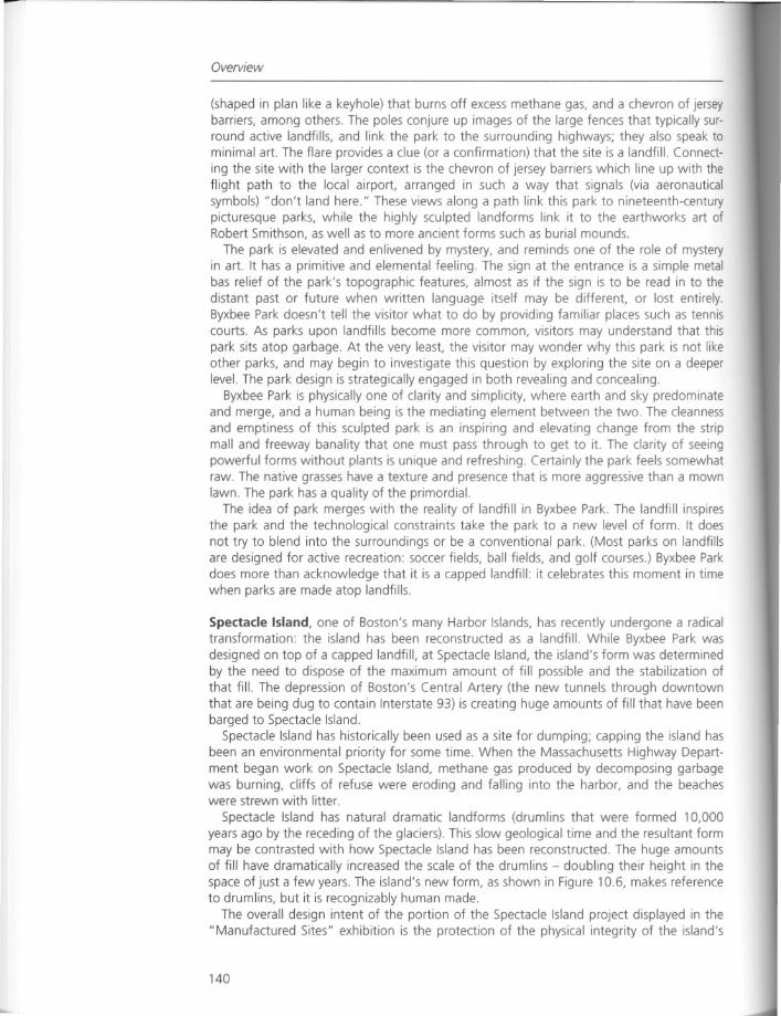
Overview
(shaped in plan like a keyhole) that burns off excess methane gas, and a chevron of jerseybarriers, among others. The poles conjure up images of the large fences that typically surround active landfills, and link the park to the surrounding highways; they also speak tominimal art. The flare provides a clue (or a confirmation) that the site is a landfill. Connecting the site with the larger context is the chevron of jersey barriers which line up with theflight path to the local airport, arranged in such a way that signals (via aeronauticalsymbols) "don't land here." These views along a path link this park to nineteenth-centurypicturesque parks, while the highly sculpted landforms link it to the earthworks art ofRobert Smithson, as well as to more ancient forms such as burial mounds.
The park is elevated and enlivened by mystery, and reminds one of the role of mysteryin art. It has a primitive and elemental feeling. The sign at the entrance is a simple metalbas relief of the park's topographic features, almost as if the sign is to be read in to thedistant past or future when written language itself may be different, or lost entirely.Byxbee Park doesn't tell the visitor what to do by providing familiar places such as tenniscourts. As parks upon landfills become more common, visitors may understand that thispark sits atop garbage. At the very least, the visitor may wonder why this park is not likeother parks, and may begin to investigate this question by exploring the site on a deeperlevel. The park design is strategically engaged in both revealing and concealing.
Byxbee Park is physically one of clarity and simplicity, where earth and sky predominateand merge, and a human being is the mediating element between the two. The cleannessand emptiness of this sculpted park is an inspiring and elevating change from the stripmall and freeway banality that one must pass through to get to it. The clarity of seeingpowerful forms without plants is unique and refreshing. Certainly the park feels somewhatraw. The native grasses have a texture and presence that is more aggressive than a mownlawn. The park has a quality of the primordial.
The idea of park merges with the reality of landfill in Byxbee Park. The landfill inspiresthe park and the technological constraints take the park to a new level of form. It doesnot try to blend into the surroundings or be a conventional park. (Most parks on landfillsare designed for active recreation: soccer fields, ball fields, and golf courses.) Byxbee Parkdoes more than acknowledge that it is a capped landfill: it celebrates this moment in timewhen parks are made atop landfills.
Spectacle Island, one of Boston's many Harbor Islands, has recently undergone a radicaltransformation: the island has been reconstructed as a landfill. While Byxbee Park wasdesigned on top of a capped landfill, at Spectacle Island, the island's form was determinedby the need to dispose of the maximum amount of fill possible and the stabilization ofthat fill. The depression of Boston's Central Artery (the new tunnels through downtownthat are being dug to contain Interstate 93) is creating huge amounts of fill that have beenbarged to Spectacle Island.
Spectacle Island has historically been used as a site for dumping; capping the island hasbeen an environmental priority for some time. When the Massachusetts Highway Department began work on Spectacle Island, methane gas produced by decomposing garbagewas burning, cliffs of refuse were eroding and falling into the harbor, and the beacheswere strewn with litter.
Spectacle Island has natural dramatic landforms (drumlins that were formed 10,000years ago by the receding of the glaciers). This slow geological time and the resultant formmay be contrasted with how Spectacle Island has been reconstructed. The huge amountsof fill have dramatically increased the scale of the drumlins - doubling their height in thespace of just a few years. The island's new form, as shown in Figure 10.6, makes referenceto drumlins, but it is recognizably human made.
The overall design intent of the portion of the Spectacle Island project displayed in the"Manufactured Sites" exhibition is the protection of the physical integrity of the island's
140
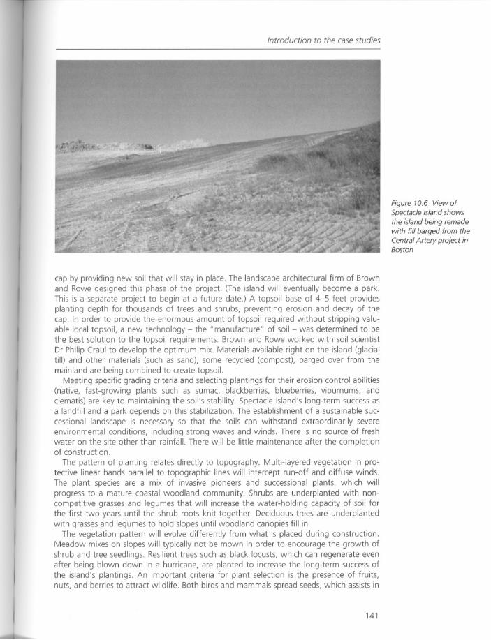
Introduction to the case studies
cap by providing new soil that will stay in place. The landscape architectural firm of Brownand Rowe designed this phase of the project. (The island will eventually become a park.This is a separate project to begin at a future date.) A topsoil base of 4-5 feet providesplanting depth for thousands of trees and shrubs, preventing erosion and decay of thecap. In order to provide the enormous amount of topsoil required without stripping valuable local topsoil, a new technology - the "manufacture" of soil - was determined to bethe best solution to the topsoil requirements. Brown and Rowe worked with soil scientistDr Philip Craul to develop the optimum mix. Materials available right on the island (glacialtill) and other materials (such as sand), some recycled (compost). barged over from themainland are being combined to create topsoil.
Meeting specific grading criteria and selecting plantings for their erosion control abilities(native, fast-growing plants such as sumac, blackberries, blueberries, viburnums, andclematis) are key to maintaining the soil's stability. Spectacle Island's long-term success asa landfill and a park depends on this stabilization. The establishment of a sustainable successional landscape is necessary so that the soils can withstand extraordinarily severeenvironmental conditions, including strong waves and winds. There is no source of freshwater on the site other than rainfall. There will be little maintenance after the completionof construction.
The pattern of planting relates directly to topography. Multi-layered vegetation in protective linear bands parallel to topographic lines will intercept run-off and diffuse winds.The plant species are a mix of invasive pioneers and successional plants, which willprogress to a mature coastal woodland community. Shrubs are underplanted with noncompetitive grasses and legumes that will increase the water-holding capacity of soil forthe first two years until the shrub roots knit together. Deciduous trees are underplantedwith grasses and legumes to hold slopes until woodland canopies fill in.
The vegetation pattern will evolve differently from what is placed during construction.Meadow mixes on slopes will typically not be mown in order to encourage the growth ofshrub and tree seedlings. Resilient trees such as black locusts, which can regenerate evenafter being blown down in a hurricane, are planted to increase the long-term success ofthe island's plantings. An important criteria for plant selection is the presence of fruits,nuts, and berries to attract wildlife. Both birds and mammals spread seeds, which assists in
141
Figure 10.6 ViewofSpectacle Island showsthe island being remadewith fill barged from theCentral Artery project inBoston
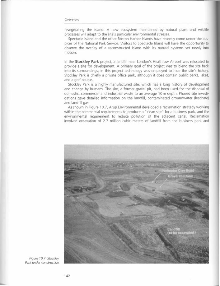
Figure 10.7 StockleyPark under construction
Overview
revegetating the island. A new ecosystem maintained by natural plant and wildlifeprocesses will adapt to the site's particular environmental stresses.
Spectacle Island and the other Boston Harbor Islands have recently come under the auspices of the National Park Service. Visitors to Spectacle Island will have the opportunity toobserve the overlay of a reconstructed island with its natural systems set newly intomotion.
In the Stockley Park project, a landfill near London's Heathrow Airport was relocated toprovide a site for development. A primary goal of the project was to blend the site backinto its surroundings; in this project technology was employed to hide the site's history.Stockley Park is chiefly a private office park, although it does contain public parks, lakes,and a golf course.
Stockley Park is a highly manufactured site, which has a long history of developmentand change by humans. The site, a former gravel pit, had been used for the disposal ofdomestic, commercial and industrial waste to an average 10m depth. Phased site investigations gave detailed information on the landfill, contaminated groundwater (leachate)and landfill gas.
As shown in Figure 10.7, Arup Environmental developed a reclamation strategy workingwithin the commercial requirements to produce a "clean site" for a business park, and theenvironmental requirement to reduce pollution of the adjacent canal. Reclamationinvolved excavation of 2.7 million cubic meters of landfill from the business park and
142
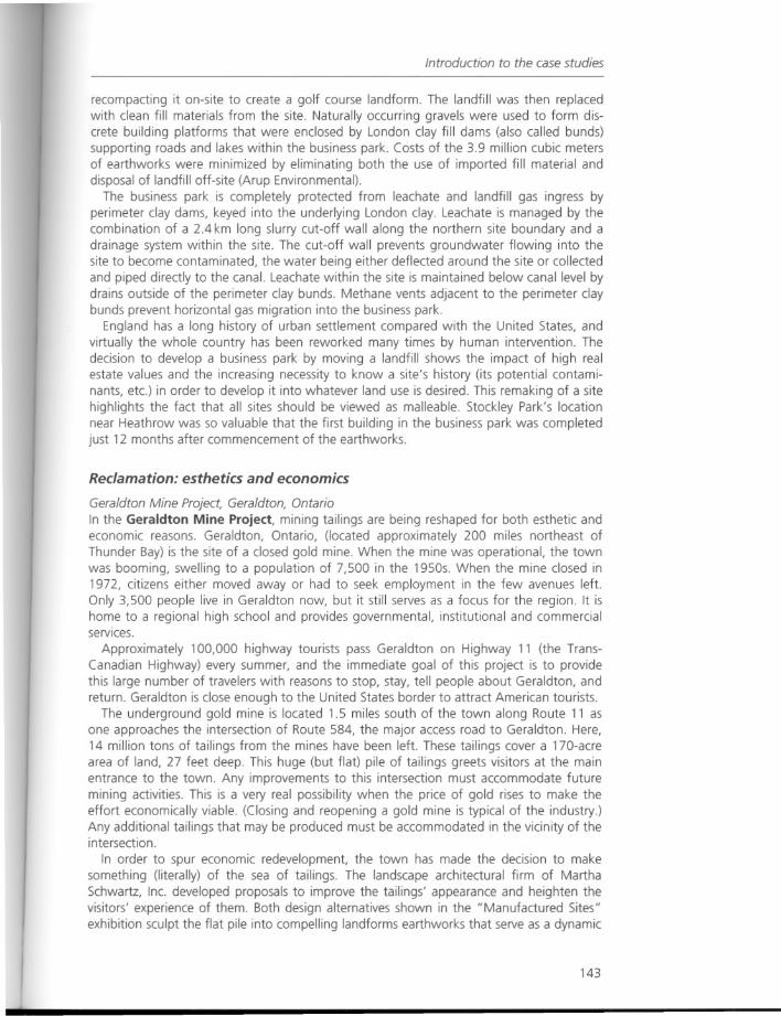
Introduction to the case studies
recompacting it on-site to create a golf course landform. The landfill was then replacedwith clean fill materials from the site. Naturally occurring gravels were used to form discrete building platforms that were enclosed by London clay fill dams (also called bunds)supporting roads and lakes within the business park. Costs of the 3.9 million cubic metersof earthworks were minimized by eliminating both the use of imported fill material anddisposal of landfill off-site (Arup Environmental).
The business park is completely protected from leachate and landfill gas ingress byperimeter clay dams, keyed into the underlying London clay. Leachate is managed by thecombination of a 2.4 km long slurry cut-off wall along the northern site boundary and adrainage system within the site. The cut-off wall prevents groundwater flowing into thesite to become contaminated, the water being either deflected around the site or collectedand piped directly to the canal. Leachate within the site is maintained below canal level bydrains outside of the perimeter clay bunds. Methane vents adjacent to the perimeter claybunds prevent horizontal gas migration into the business park.
England has a long history of urban settlement compared with the United States, andvirtually the whole country has been reworked many times by human intervention. Thedecision to develop a business park by moving a landfill shows the impact of high realestate values and the increasing necessity to know a site's history (its potential contaminants, etc.) in order to develop it into whatever land use is desired. This remaking of a sitehighlights the fact that all sites should be viewed as malleable. Stockley Park's locationnear Heathrow was so valuable that the first building in the business park was completedjust 12 months after commencement of the earthworks.
Reclamation: esthetics and economics
Geraldton Mine Project, Geraldton, OntarioIn the Geraldton Mine Project, mining tailings are being reshaped for both esthetic andeconomic reasons. Geraldton, Ontario, (located approximately 200 miles northeast ofThunder Bay) is the site of a closed gold mine. When the mine was operational, the townwas booming, swelling to a population of 7,500 in the 1950s. When the mine closed in1972, citizens either moved away or had to seek employment in the few avenues left.Only 3,500 people live in Geraldton now, but it still serves as a focus for the region. It ishome to a regional high school and provides governmental, institutional and commercialservices.
Approximately 100,000 highway tourists pass Geraldton on Highway 11 (the TransCanadian Highway) every summer, and the immediate goal of this project is to providethis large number of travelers with reasons to stop, stay, tell people about Geraldton, andreturn. Geraldton is close enough to the United States border to attract American tourists.
The underground gold mine is located 1.5 miles south of the town along Route 11 asone approaches the intersection of Route 584, the major access road to Geraldton. Here,14 million tons of tailings from the mines have been left. These tailings cover a 170-acrearea of land, 27 feet deep. This huge (but flat) pile of tailings greets visitors at the mainentrance to the town. Any improvements to this intersection must accommodate futuremining activities. This is a very real possibility when the price of gold rises to make theeffort economically viable. (Closing and reopening a gold mine is typical of the industry.)Any additional tailings that may be produced must be accommodated in the vicinity of theintersection.
In order to spur economic redevelopment, the town has made the decision to makesomething (literally) of the sea of tailings. The landscape architectural firm of MarthaSchwartz, Inc. developed proposals to improve the tailings' appearance and heighten thevisitors' experience of them. Both design alternatives shown in the "Manufactured Sites"exhibition sculpt the flat pile into compelling landforms earthworks that serve as a dynamic
143
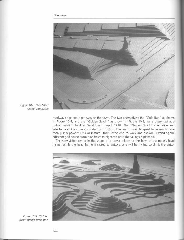
Figure 10.8 "Gold Bar"design alternative
Figure 10.9 "Golden
Scroll" design alternative
Overview
roadway edge and a gateway to the town. The two alternatives: the "Gold Bar," as shownin Figure 10.8, and the "Golden Scroll," as shown in Figure 10.9, were presented at apublic meeting held in Geraldton in April 1998. The "Golden Scroll" alternative wasselected and it is currently under construction. The landform is designed to be much morethan just a powerful visual feature. Trails invite one to walk and explore. Extending theadjacent golf course from nine holes to eighteen onto the tailings is planned.
The new visitor center in the shape of a tower relates to the form of the mine's headframe. While the head frame is closed to visitors, one will be invited to climb the visitor
144
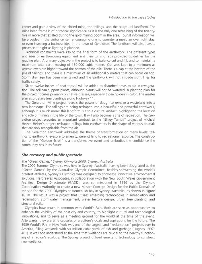
Introduction to the case studies
center and gain a view of the closed mine, the tailings, and the sculptural landform. Themine head frame is of historical significance as it is the only one remaining of the twentyfive or more that existed during the gold mining boom in the area. Tourist information willbe provided in the visitor center, encouraging one to consider a meal, an overnight stay,or even investing a business idea in the town of Geraldton. The landform will also have apresence at night as lighting is planned.
Technical constraints were key to the final form of the earthwork. The different typesand sizes of earth-moving equipment and their turning radii provided guidelines for thegrading plan. A primary objective in the project is to balance cut and fill, and to maintain amaximum total earth moving of 150,000 cubic meters. Cut was kept to a minimum asarsenic levels are higher toward the bottom of the pile. There is a cap at the bottom of thepile of tailings, and there is a maximum of an additional 5 meters that can occur on top.Storm drainage has been maintained and the earthwork will not impede sight lines fortraffic safety.
Six to twelve inches of peat topsoil will be added to disturbed areas to aid in revegetation. The soil can support plants, although plants will not be watered. A planting plan forthe project focuses primarily on native grasses, especially those golden in color. The masterplan also details tree plantings along Highway 11.
The Geraldton Mine project reveals the power of design to remake a wasteland into anew landscape. The tailings are being reshaped into a beautiful and powerful earthwork,although it is much more: this landform is also a cultural artifact, highlighting the locationand role of mining in the life of the town. It will also become a site of recreation. The Geraldton project provides an important contrast to the "Effigy Tumuli" project of MichaelHeizer. Heizer's project reshaped tailings into earthworks in the shape of various animalsthat are only recognizable from the air.
The Geraldton earthwork addresses the theme of transformation on many levels: tailings to earthwork, eyesore to amenity, derelict land to recreational resource. The construction of the "Golden Scroll" is a transformative event and embodies the confidence the
community has in its future.
Site recovery and public spectacle
The "Green Games, " Sydney Olympics 2000, Sydney, AustraliaThe 2000 Summer Olympics was held in Sydney, Australia, having been designated as the"Green Games" by the Australian Olympic Committee. Besides showcasing the world'sgreatest athletes, Sydney's Olympics was designed to showcase innovative environmentalsolutions. Hargreaves Associates, in collaboration with the New South Wales GovernmentArchitect Design Directorate (GADD), was commissioned in 1996 by the OlympicCoordination Authority to create a new Master Concept Design for the Public Domain ofthe site for the 2000 Olympics at Homebush Bay in Sydney, Australia, as shown in Figure10.10. The result was a project that utilizes emerging technologies in remediation andreclamation, stormwater management, water feature design, urban tree planting, andstructural soils.
Olympics have much in common with World's Fairs. Both are seen as opportunities toenhance the visibility of the host city and country, to highlight cultural and technologicalinnovations, and to serve as a meeting ground for the world at the time of the event.Afterwards, they are time capsules of a culture's goals and aspirations for the future. The1939 World's Fair in New York was one of the largest land "reclamation" projects ever inAmerica, filling wetlands with six million cubic yards of ash and garbage (Hughes 1997:461). It was not understood at the time that wetlands are crucial to the healthy functioning of a region's ecology. The Sydney project utilized emerging technology to constructnew wetlands.
145
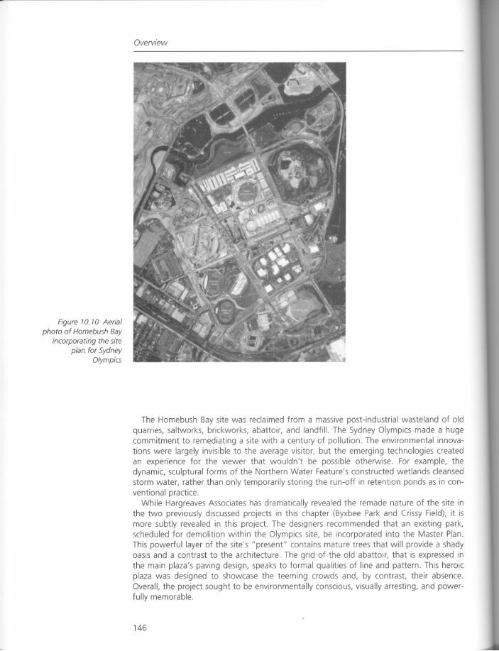
Figure 10. 10 Aerial
phata af Hamebush Bayincorparating the site
plan far SydneyOlympics
Overview
The Homebush Bay site was reclaimed from a massive post-industrial wasteland of oldquarries, saltworks, brickworks, abattoir, and landfill. The Sydney Olympics made a hugecommitment to remediating a site with a century of pollution. The environmental innovations were largely invisible to the average visitor, but the emerging technologies createdan experience for the viewer that wouldn't be possible otherwise. For example, thedynamic, sculptural forms of the Northern Water Feature's constructed wetlands cleansedstorm water, rather than only temporarily storing the run-off in retention ponds as in conventional practice.
While Hargreaves Associates has dramatically revealed the remade nature of the site inthe two previously discussed projects in this chapter (Byxbee Park and Crissy Field), it ismore subtly revealed in this project. The designers recommended that an existing park,scheduled for demolition within the Olympics site, be incorporated into the Master Plan.This powerful layer of the site's "present" contains mature trees that will provide a shadyoasis and a contrast to the architecture. The grid of the old abattoir, that is expressed inthe main plaza's paving design, speaks to formal qualities of line and pattern. This heroicplaza was designed to showcase the teeming crowds and, by contrast, their absence.Overall, the project sought to be environmentally conscious, visually arresting, and powerfully memorable.
146
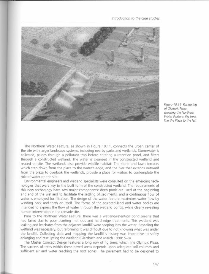
Introduction to the case studies
The Northern Water Feature, as shown in Figure 10.11, connects the urban center ofthe site with larger landscape systems, including nearby parks and wetlands. Stormwater iscollected, passes through a pollutant trap before entering a retention pond, and filtersthrough a constructed wetland. The water is cleansed in the constructed wetland andreused on-site. The wetlands also provide wildlife habitat. The stone and lawn terraceswhich step down from the plaza to the water's edge, and the pier that extends outwardfrom the plaza to overlook the wetlands, provide a place for visitors to contemplate therole of water on the site.
Environmental engineers and wetland specialists were consulted on the emerging technologies that were key to the built form of the constructed wetland. The requirements ofthis new technology have two major components: deep pools are used at the beginningand end of the wetland to facilitate the settling of sediments, and a continuous flow ofwater is employed for filtration. The design of the water feature maximizes water flow bywinding back and forth on itself. The forms of the sculpted land and water bodies areintended to express the flow of water through the wetland ponds, while clearly revealinghuman intervention in the remade site.
Prior to the Northern Water Feature, there was a wetland/retention pond on-site thathad failed due to poor planting methods and hard edge treatments. This wetland wasleaking and leachates from the adjacent landfill were seeping into the water. Resealing thewetland was necessary, but reforming it was difficult due to not knowing what was underthe landfill. Collecting data and mapping the landfill's history was imperative to safelyenlarging and resculpting the wetland (Giersbach and March 1998: 5-8).
The Master Concept Design features a long row of fig trees, which line Olympic Plaza.The success of trees within these paved areas depends upon adequate soil volumes andsufficient air and water reaching the root zones. The pavement had to be designed to
147
Figure 10. 11 Rendering
of Olympic Plazashowing the NorthernWater Feature. Fig treesline the Plaza to the left
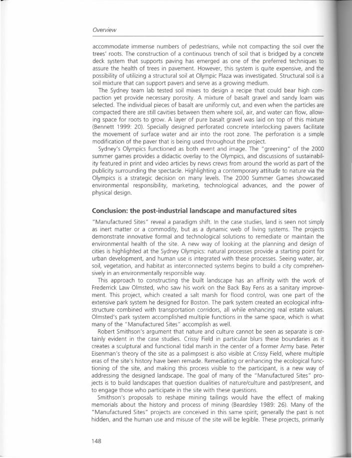
Overview
accommodate immense numbers of pedestrians, while not compacting the soil over thetrees' roots. The construction of a continuous trench of soil that is bridged by a concretedeck system that supports paving has emerged as one of the preferred techniques toassure the health of trees in pavement. However, this system is quite expensive, and thepossibility of utilizing a structural soil at Olympic Plaza was investigated. Structural soil is asoil mixture that can support pavers and serve as a growing medium.
The Sydney team lab tested soil mixes to design a recipe that could bear high compaction yet provide necessary porosity. A mixture of basalt gravel and sandy loam wasselected. The individual pieces of basalt are uniformly cut, and even when the particles arecompacted there are still cavities between them where soil, air, and water can flow, allowing space for roots to grow. A layer of pure basalt gravel was laid on top of this mixture(Bennett 1999: 20). Specially designed perforated concrete interlocking pavers facilitatethe movement of surface water and air into the root zone. The perforation is a simplemodification of the paver that is being used throughout the project.
Sydney's Olympics functioned as both event and image. The "greening" of the 2000summer games provides a didactic overlay to the Olympics, and discussions of sustainability featured in print and video articles by news crews from around the world as part of thepublicity surrounding the spectacle. Highlighting a contemporary attitude to nature via theOlympics is a strategic decision on many levels. The 2000 Summer Games showcasedenvironmental responsibility, marketing, technological advances, and the power ofphysical design.
Conclusion: the post-industrial landscape and manufactured sites
"Manufactured Sites" reveal a paradigm shift. In the case studies, land is seen not simplyas inert matter or a commodity, but as a dynamic web of living systems. The projectsdemonstrate innovative formal and technological solutions to remediate or maintain theenvironmental health of the site. A new way of looking at the planning and design ofcities is highlighted at the Sydney Olympics: natural processes provide a starting point forurban development, and human use is integrated with these processes. Seeing water, air,soil, vegetation, and habitat as interconnected systems begins to build a city comprehensively in an environmentally responsible way.
This approach to constructing the built landscape has an affinity with the work ofFrederrick Law Olmsted, who saw his work on the Back Bay Fens as a sanitary improvement. This project, which created a salt marsh for flood control, was one part of theextensive park system he designed for Boston. The park system created an ecological infrastructure combined with transportation corridors, all while enhancing real estate values.Olmsted's park system accomplished multiple functions in the same space, which is whatmany of the "Manufactured Sites" accomplish as well.
Robert Smithson's argument that nature and culture cannot be seen as separate is certainly evident in the case studies. Crissy Field in particular blurs these boundaries as itcreates a sculptural and functional tidal marsh in the center of a former Army base. PeterEisenman's theory of the site as a palimpsest is also visible at Crissy Field, where multipleeras of the site's history have been remade. Remediating or enhancing the ecological functioning of the site, and making this process visible to the participant, is a new way ofaddressing the designed landscape. The goal of many of the "Manufactured Sites" projects is to build landscapes that question dualities of nature/culture and past/present, andto engage those who participate in the site with these questions.
Smithson's proposals to reshape mining tailings would have the effect of makingmemorials about the history and process of mining (Beardsley 1989: 26). Many of the"Manufactured Sites" projects are conceived in this same spirit; generally the past is nothidden, and the human use and misuse of the site will be legible. These projects, primarily
148
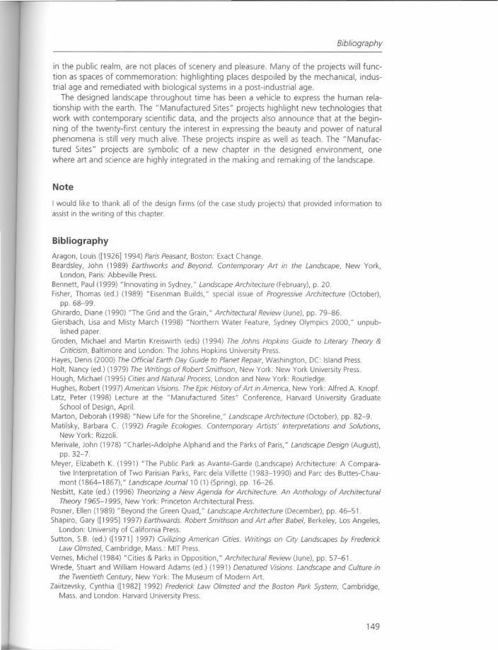
Bibliography
in the public realm, are not places of scenery and pleasure. Many of the projects will function as spaces of commemoration: highlighting places despoiled by the mechanical, industrial age and remediated with biological systems in a post-industrial age.
The designed landscape throughout time has been a vehicle to express the human relationship with the earth. The" Manufactured Sites" projects highlight new technologies thatwork with contemporary scientific data, and the projects also announce that at the beginning of the twenty-first century the interest in expressing the beauty and power of naturalphenomena is still very much alive. These projects inspire as well as teach. The "Manufactured Sites" projects are symbolic of a new chapter in the designed environment, onewhere art and science are highly integrated in the making and remaking of the landscape.
Note
I would like to thank all of the design firms (of the case study projects) that provided information to
assist in the writing of this chapter.
Bibliography
Aragon, Louis ([1926] 1994) Paris Peasant, Boston: Exact Change.Beardsley, John (1989) Earthworks and Beyond. Contemporary Art in the Landscape, New York,
London, Paris: Abbeville Press.
Bennett, Paul (1999) "Innovating in Sydney," Landscape Architecture (February), p. 20.Fisher, Thomas (ed.) (1989) "Eisenman Builds," special issue of Progressive Architecture (October),
pp.68-99.Ghirardo, Diane (1990) "The Grid and the Grain," Architectural Review (June), pp. 79-86.Giersbach, Lisa and Misty March (1998) "Northern Water Feature, Sydney Olympics 2000," unpub
lished paper.
Groden, Michael and Martin Kreiswirth (eds) (1994) The Johns Hopkins Guide to Literary Theory &Criticism, Baltimore and London: The Johns Hopkins University Press.
Hayes, Denis (2000) The Official Earth Day Guide to Planet Repair, Washington, DC: Island Press.Holt, Nancy (ed.) (1979) The Writings of Robert Smithson, New York: New York University Press.Hough, Michael (1995) Cities and Natural Process, London and New York: Routledge.Hughes, Robert (1997) American Visions. The Epic History of Art in America, New York: Alfred A. Knopf.Latz, Peter (1998) Lecture at the "Manufactured Sites" Conference, Harvard University Graduate
School of Design, April.Marton, Deborah (1998) "New Life for the Shoreline," Landscape Architecture (October), pp. 82-9.Matilsky, Barbara C. (1992) Fragile Ecologies. Contemporary Artists' Interpretations and Solutions,
New York: Rizzoli.
Merivale, John (1978) "Charles-Adolphe Alphand and the Parks of Paris," Landscape Design (August),pp.32-7.
Meyer, Elizabeth K. (1991) "The Public Park as Avante-Garde (Landscape) Architecture: A Comparative Interpretation of Two Parisian Parks, Parc dela Villette (1983-1990) and Parc des Buttes-Chau
mont (1864-1867)," Landscape Journal 10 (1) (Spring), pp. 16-26.Nesbitt, Kate (ed.) (1996) Theorizing a New Agenda for Architecture. An Anthology of Architectural
Theory 1965-1995, New York: Princeton Architectural Press.Posner, Ellen (1989) "Beyond the Green Quad," Landscape Architecture (December), pp. 46-51.
Shapiro, Gary ([1995] 1997) Earthwards. Robert Smithson and Art after Babel, Berkeley, Los Angeles,London: University of California Press.
Sutton, S.B. (ed.) ([1971] 1997) Civilizing American Cities. Writings on City Landscapes by FrederickLaw Olmsted, Cambridge, Mass.: MIT Press.
Vernes, Michel (1984) "Cities & Parks in Opposition," Architectural Review (June), pp. 57-61.Wrede, Stuart and William Howard Adams (ed.) (1991) Denatured Visions. Landscape and Culture in
the Twentieth Century, New York: The Museum of Modern Art.Zaiitzevsky, Cynthia ([1982] 1992) Frederick Law Olmsted and the Boston Park System, Cambridge,
Mass. and London: Harvard University Press.
149
Chapter 11
Landscape Park Duisburg-Nord:the metamorphosis of an industrial site
Peter Latz
Introduction
The following essay discusses the possibilities of improvement for the living conditions of arun-down old industrialized region in the northern Ruhr district of Germany, the reanimation of the devastated areas and their regeneration as a landscape for a densely populatedterritory. It deals with ideas to integrate, shape, develop and interlink the existing patternsthat were formed by its previous industrial use, and suggests a new interpretation with anew syntax. The project started in 1991 after an international competition with the masterplan for the whole site and continued with the planning and implementation of manypartial projects until 1999. Besides the realization of a 230-hectare landscape park withpromenades and footbridges on different levels, with places and gardens and rebuiltwater basins and channels, recycling and the dealing with historical contamination weremajor tasks on this site.
Landscape Park Duisburg-Nord
There, in the so-called Emscher district, the coal, iron and steel industries, shrunken byperiodical crises, have left behind a bizarre landscape: spaces torn to pieces and environmental damage, land settlement with swamps and polders, slag heaps instead of floodplain forests and soils polluted with polyaromatic hydrocarbons and heavy metals.
To make this area with 2.5 million inhabitants attractive again for new investment, thefundamental ecological base of the landscape has to be restored. This is the aim of theInternational Building Exhibition Emscher Park (IBA). The Landscape Park Duisburg-Nord isa key project of the IBA that reflects new ideas about landscape and nature. Old industrialsubstance is the basis of the park and the existing blast furnaces are its symbol. The metamorphosis of the hard industrial structure into a public park is symbolized by an artifact ofseven by seven cast iron plates amidst the blast furnace plant. The original idea for this"Piazza Metallica," as shown in Figure 11.1, was to represent in forty-nine cast iron platesthe iron manufacturing process in both its molten and hardened states. Melting and hardening was to be simulated by water flowing and settling on the surfaces. Since the proposed casting would have been very expensive, we found iron plates for the Piazza in thestill productive pig-iron casting works. They were used to cover casting molds and had towithstand molten metal at temperatures of 1,600 degrees farenheit. This process causedthe plates to take on individual forms of erosion. The plates, each weighing 7-8 tons,
150
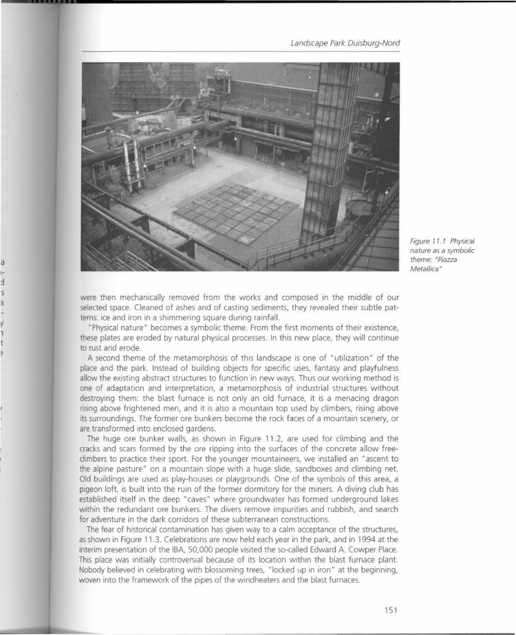
Landscape Park Duisburg-Nord
were then mechanically removed from the works and composed in the middle of ourselected space. Cleaned of ashes and of casting sediments, they revealed their subtle patterns: ice and iron in a shimmering square during rainfall.
"Physical nature" becomes a symbolic theme. From the first moments of their existence,these plates are eroded by natural physical processes. In this new place, they will continueto rust and erode.
A second theme of the metamorphosis of this landscape is one of "utilization" of theplace and the park. Instead of building objects for specific uses, fantasy and playfulnessallow the existing abstract structures to function in new ways. Thus our working method isone of adaptation and interpretation, a metamorphosis of industrial structures withoutdestroying them: the blast furnace is not only an old furnace, it is a menacing dragonrising above frightened men, and it is also a mountain top used by climbers, rising aboveits surroundings. The former ore bunkers become the rock faces of a mountain scenery, orare transformed into enclosed gardens.
The huge ore bunker walls, as shown in Figure 11.2, are used for climbing and thecracks and scars formed by the ore ripping into the surfaces of the concrete allow freeclimbers to practice their sport. For the younger mountaineers, we installed an "ascent tothe alpine pasture" on a mountain slope with a huge slide, sandboxes and climbing net.Old buildings are used as play-houses or playgrounds. One of the symbols of this area, apigeon loft, is built into the ruin of the former dormitory for the miners. A diving club hasestablished itself in the deep "caves" where groundwater has formed underground lakeswithin the redundant ore bunkers. The divers remove impurities and rubbish, and searchfor adventure in the dark corridors of these subterranean constructions.
The fear of historical contamination has given way to a calm acceptance of the structures,as shown in Figure 11.3. Celebrations are now held each year in the park, and in 1994 at theinterim presentation of the ISA, 50,000 people visited the so-called Edward A. Cowper Place.This place was initially controversial because of its location within the blast furnace plant.Nobody believed in celebrating with blossoming trees, "locked up in iron" at the beginning,woven into the framework of the pipes of the wind heaters and the blast furnaces.
151
Figure 11. 1 Physicalnature as a symbolictheme: "PiazzaMetal/ica"
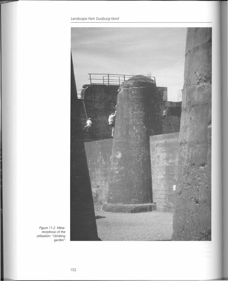
Figure 11.2 Meta
morphosis of theutilization: NC/imbing
gardenN
Landscape Park Duisburg-Nord
152
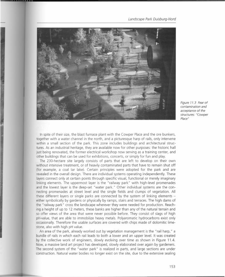
Landscape Park Duisburg-Nord
In spite of their size, the blast furnace plant with the Cowper Place and the ore bunkers,together with a water channel in the north, and a picturesque harp of rails, only intervenewithin a small section of the park. This zone includes buildings and architectural structures. As an industrial heritage, they are available now for other purposes: the historic halljust being renovated, the former electrical workshop now serving as a training center, andother buildings that can be used for exhibitions, concerts, or simply for fun and play.
The 230-hectare site largely consists of parts that are left to develop on their ownwithout intensive treatment, or of heavily contaminated parts that have to remain shut off(for example, a coal tar lake). Certain principles were adopted for the park and arerevealed in the overall design. There are individual systems operating independently. Theselayers connect only at certain points through specific visual, functional or merely imaginarylinking elements. The uppermost layer is the "railway park" with high-level promenadesand the lowest layer is the deep-set "water park." Other individual systems are the connecting promenades at street level and the single fields and clumps of vegetation. Allthese different layers or single parks are connected by the system of linking elements either symbolically by gardens or physically by ramps, stairs and terraces. The high dams ofthe "railway park" cross the landscape wherever they were needed for production. Reaching a height of up to 12 meters, these banks are higher than any of the natural terrain andso offer views of the area that were never possible before. They consist of slags of highpH-value, that are able to immobilize heavy metals. Polyaromatic hydrocarbons exist onlyoccasionally. Therefore the usable surfaces are covered with chips made of dolomitic limestone, also with high pH value.
An area of the park, already worked out by vegetation management is the "rail harp," abundle of rails in which each rail leads to both a lower and an upper level. It was createdby the collective work of engineers, slowly evolving over time as shown in Figure 11.4.Now, a massive land art project has developed, slowly elaborated over again by gardeners.The second system of the "water park" is realized in parts, and large sections are underconstruction. Natural water bodies no longer exist on the site, due to the extensive sealing
153
Figure 11.3 Fear ofcontamination and
acceptance of thestructures: ·CowperPlace"
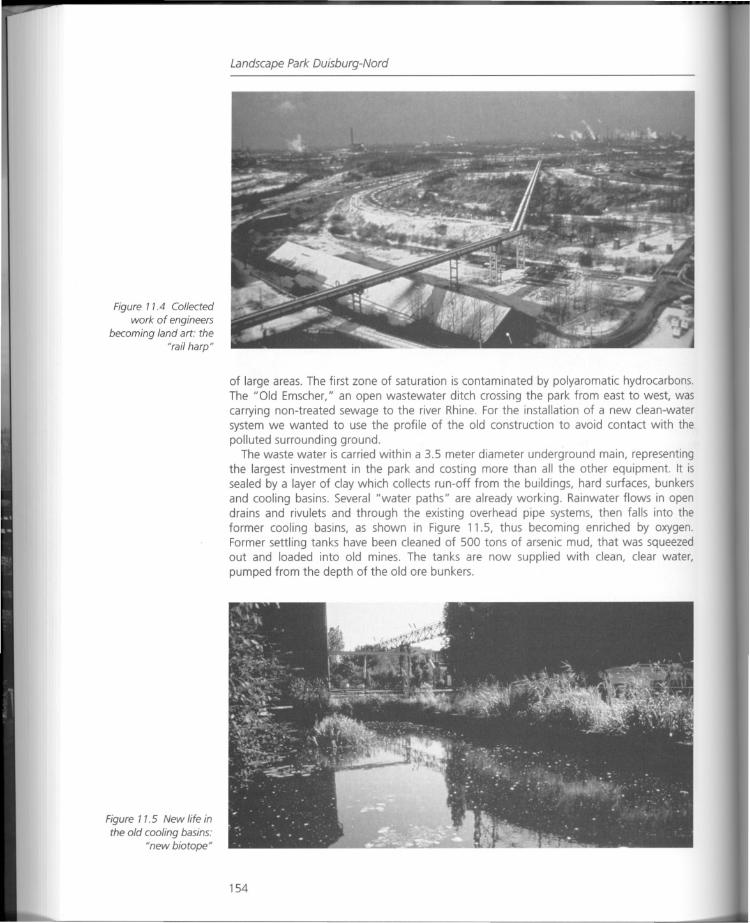
Figure 11.4 Collectedwork of engineers
becoming land art: the"rail harp"
Figure 11.5 New life inthe old cooling basins:
"new biotope"
Landscape Park Duisburg-Nord
of large areas. The first zone of saturation is contaminated by polyaromatic hydrocarbons.The "Old Emscher," an open wastewater ditch crossing the park from east to west, wascarrying non-treated sewage to the river Rhine. For the installation of a new clean-watersystem we wanted to use the profile of the old construction to avoid contact with thepolluted surrounding ground.
The waste water is carried within a 3.5 meter diameter underground main, representingthe largest investment in the park and costing more than all the other equipment. It issealed by a layer of clay which collects run-off from the buildings, hard surfaces, bunkersand cooling basins. Several "water paths" are already working. Rainwater flows in opendrains and rivulets and through the existing overhead pipe systems, then falls into theformer cooling basins, as shown in Figure 11.5, thus becoming enriched by oxygen.Former settling tanks have been cleaned of 500 tons of arsenic mud, that was squeezedout and loaded into old mines. The tanks are now supplied with clean, clear water,pumped from the depth of the old are bunkers.
154
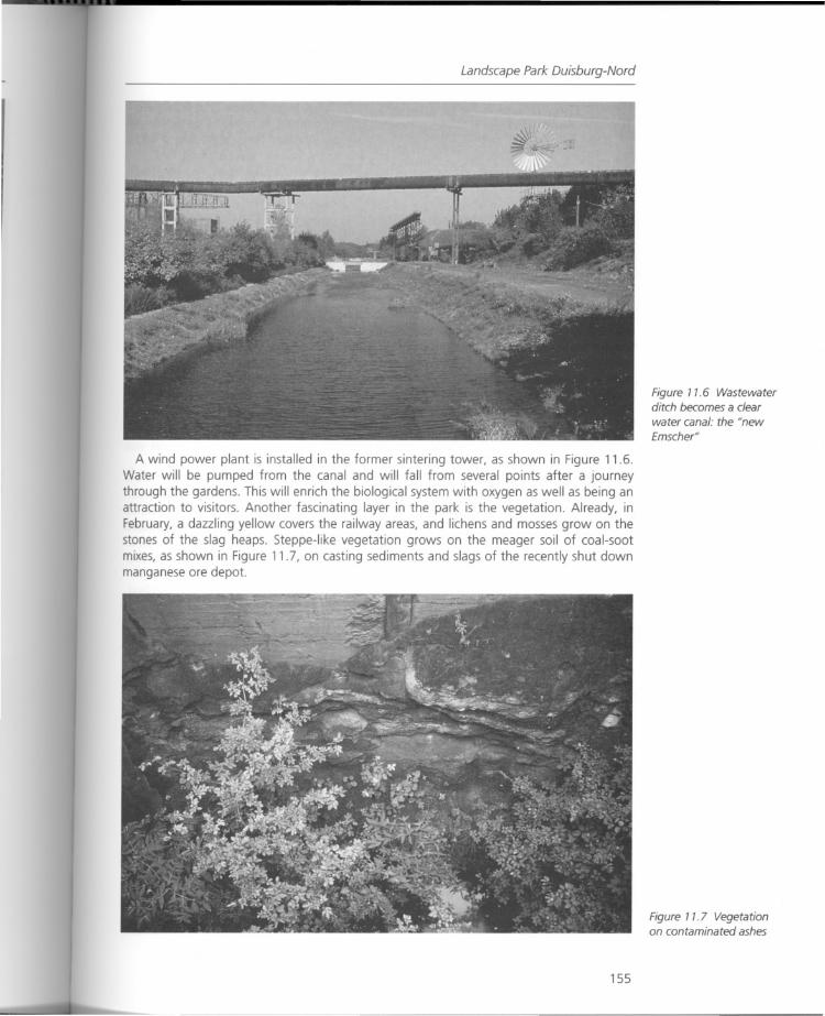
Landscape Park Ouisburg-Nord
A wind power plant is installed in the former sintering tower, as shown in Figure 11.6.Water will be pumped from the canal and will fall from several points after a journeythrough the gardens. This will enrich the biological system with oxygen as well as being anattraction to visitors. Another fascinating layer in the park is the vegetation. Already, inFebruary, a dazzling yellow covers the railway areas, and lichens and mosses grow on thestones of the slag heaps. Steppe-like vegetation grows on the meager soil of coal-sootmixes, as shown in Figure 11.7, on casting sediments and slags of the recently shut downmanganese are depot.
155
Figure 11.6 Wastewaterditch becomes a clearwater canal: the "newEmscher"
Figure 11.7 Vegetationon contaminated ashes
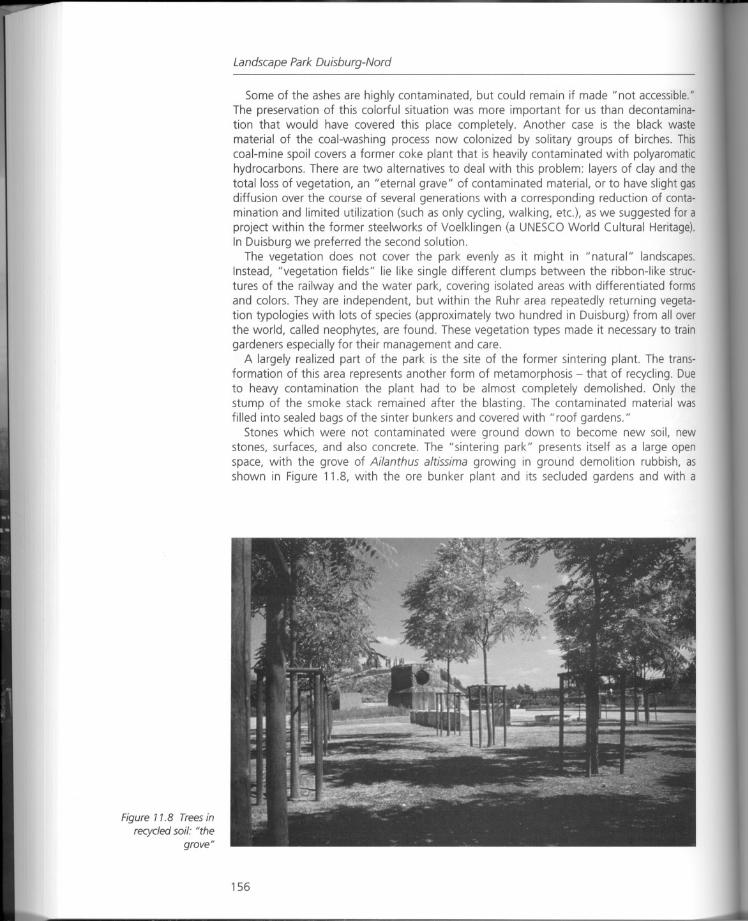
Figure 11.8 Trees inrecycled soil: "the
grove"
Landscape Park Duisburg-Nord
Some of the ashes are highly contaminated, but could remain if made "not accessible."The preservation of this colorful situation was more important for us than decontamination that would have covered this place completely. Another case is the black wastematerial of the coal-washing process now colonized by solitary groups of birches. Thiscoal-mine spoil covers a former coke plant that is heavily contaminated with polyaromatichydrocarbons. There are two alternatives to deal with this problem: layers of clay and thetotal loss of vegetation, an "eternal grave" of contaminated material, or to have slight gasdiffusion over the course of several generations with a corresponding reduction of contamination and limited utilization (such as only cycling, walking, etc.), as we suggested for aproject within the former steelworks of Voelklingen (a UNESCO World Cultural Heritage).In Duisburg we preferred the second solution.
The vegetation does not cover the park evenly as it might in "natural" landscapes,Instead, "vegetation fields" lie like single different clumps between the ribbon-like structures of the railway and the water park, covering isolated areas with differentiated formsand colors, They are independent, but within the Ruhr area repeatedly returning vegetation typologies with lots of species (approximately two hundred in Duisburg) from alloverthe world, called neophytes, are found. These vegetation types made it necessary to traingardeners especially for their management and care.
A largely realized part of the park is the site of the former sintering plant. The transformation of this area represents another form of metamorphosis - that of recycling. Dueto heavy contamination the plant had to be almost completely demolished. Only thestump of the smoke stack remained after the blasting. The contaminated material wasfilled into sealed bags of the sinter bunkers and covered with "roof gardens."
Stones which were not contaminated were ground down to become new soil, newstones, surfaces, and also concrete. The "sintering park" presents itself as a large openspace, with the grove of Ailanthus altissima growing in ground demolition rubbish, asshown in Figure 11.8, with the ore bunker plant and its secluded gardens and with a
156
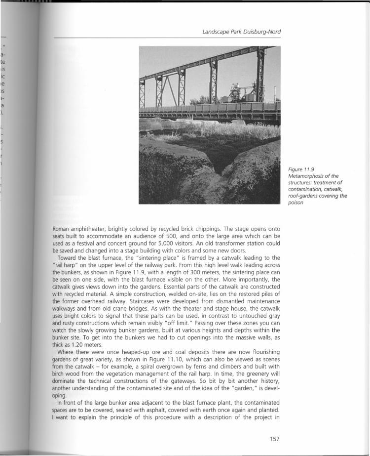
Landscape Park Duisburg-Nord
Roman amphitheater, brightly colored by recycled brick chippings. The stage opens ontoseats built to accommodate an audience of 500, and onto the large area which can beused as a festival and concert ground for 5,000 visitors. An old transformer station couldbe saved and changed into a stage building with colors and some new doors.
Toward the blast furnace, the "sintering place" is framed by a catwalk leading to the"rail harp" on the upper level of the railway park. From this high level walk leading acrossthe bunkers, as shown in Figure 11.9, with a length of 300 meters, the sintering place canbe seen on one side, with the blast furnace visible on the other. More importantly, thecatwalk gives views down into the gardens. Essential parts of the catwalk are constructedwith recycled material. A simple construction, welded on-site, lies on the restored piles ofthe former overhead railway. Staircases were developed from dismantled maintenancewalkways and from old crane bridges. As with the theater and stage house, the catwalkuses bright colors to signal that these parts can be used, in contrast to untouched grayand rusty constructions which remain visibly" off limit." Passing over these zones you canwatch the slowly growing bunker gardens, built at various heights and depths within thebunker site. To get into the bunkers we had to cut openings into the massive walls, asthick as 1.20 meters.
Where there were once heaped-up ore and coal deposits there are now flourishinggardens of great variety, as shown in Figure 11.10, which can also be viewed as scenesfrom the catwalk - for example, a spiral overgrown by ferns and climbers and built withbirch wood from the vegetation management of the rail harp. In time, the greenery willdominate the technical constructions of the gateways. So bit by bit another history,another understanding of the contaminated site and of the idea of the" garden," is developing.
In front of the large bunker area adjacent to the blast furnace plant, the contaminatedspacesare to be covered, sealed with asphalt, covered with earth once again and planted.I want to explain the principle of this procedure with a description of the project in
157
Figure 11.9Metamorphosis of thestructures: treatment of
contamination, catwalk,
roof-gardens covering thepoison
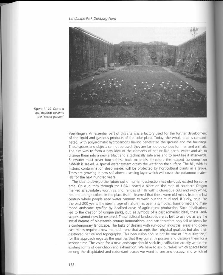
Figure 7 7. 7a Ore andcoal deposits become
the "secret garden"
Landscape Park Duisburg-Nord
Voelklingen. An essential part of this site was a factory used for the further developmentof the liquid and gaseous products of the coke plant. Today, the whole area is contaminated, with polyaromatic hydrocarbons having penetrated the ground and the buildings.These spaces and objects cannot be used, they are far too poisonous for men and animals.The aim was to form a new idea of the elements of nature like earth, water and air, to
change them into a new artifact and a technically safe area and to re-utilize it afterwards.Rainwater must never touch these toxic materials, therefore the heaped up demolitionrubbish is sealed. A special water system drains the water on the surface. The hill, with itshistoric contamination deep inside, will be protected by horticultural plants in a grove.Trees are growing in new soil above a sealing layer which will cover the poisonous materials for the next hundred years.
The idea to develop the future out of human destruction has obviously existed for sometime. On a journey through the USA I noted a place on the map of southern Oregonmarked as absolutely worth visiting: ranges of hills with picturesque cuts and with white,red and orange colors. In the place itself, I learned that these were old mines from the lastcentury where people used water cannons to wash out the mud and, if lucky, gold. Forthe past 200 years, the ideal image of nature has been a symbolic, transformed and manmade landscape, typified by idealized areas of agricultural production. Such idealizationsled to the creation of unique parks, but, as symbols of a past romantic ideal, these landscapes cannot now be restored. These cultural landscapes are as lost to us now as are thesocial dreams of nineteenth-century Romanticism, and can therefore only fail as ideals fora contemporary landscape. The tasks of dealing with run-down industrial areas and opencast mines require a new method - one that accepts their physical qualities but also theirdestroyed nature and topography. This new vision should not be one of "re-cultivation,"for this approach negates the qualities that they currently possess and destroys them for asecond time. The vision for a new landscape should seek its justification exactly within theexisting forms of demolition and exhaustion. We have to ask ourselves which spaces fromamong the dilapidated and redundant places we want to use and occupy, and which of
158
Project information and data
those have to be changed by the mark of a cultural intervention or the remediation ofhistorical contamination.
Would it not be better to attach to the ideal image of our occidental culture, to "paradise," an oasis in the desert, a place where man has to make his way against the rigors ofphysical nature? This imagination of an oasis as a garden in desolate spaces is my idealtype of discourse with the nature of old industrial sites, which in their parts can be left tothemselvesto develop the fantastic images of the future from already existing formations- creating values between art and nature in a way which could never be made by theartist nor mere nature alone.
Summary
One question seems to be unresolved: the relation between the function of the park as amunicipal open space and its importance for tourism. There are issues arising from it concerning the distribution of funds, the aims and objectives of the new operating company,and of meaning. This becomes apparent with the secondary questions that are discussedvehemently: for example, is there to be fencing and entrance fees to visit the blast furnaceplant; what is the level of security for every little part; what is the significance of the children's playgrounds? In reality, each of the individual parts of the park are clearly assignedto defined aims and functions and work out quite well.
Visitors get used especially to the central part where all the events and festivals are happening. Other parts of the park recede into the background. There might also be blameattached to the site of the water park, still under construction, that divides the parklengthways. We shall see how the uses will change once again after its completion in1999.
We tried to get an answer concerning the behavioral patterns of visitors. A group ofstudents were comparing answers and comments given in the landscape park with thoseexpressed in conventional commercial parks. This attempt at sociological analysis did notresult in significant statements - apart from three conclusions:
• The preserved blast furnaces play an important role as a major attraction.• Visits to the park for individual and personal interest and pursuits are uppermost.• The primary motive for a visit to the park is the unique atmosphere.
Project information and data
Project
Landscape Park Duisburg-Nord, a project of the International Building Exhibition EmscherPark(IBA).
Location
In the north of Duisburg between the urban districts of Hamborn and Meiderich.
Total area
230 hectares.
Competition
International cooperative competition 1990.Main planning and realization phase: 1991-9 (end of the IBA), planning and implementation of some minor projects continuing.
159
Landscape Park Duisburg-Nord
Client
Landesentwickl ungsgesellschaft Nord rhe in-Westfa len.
LEG NRW als Treuhander der Stadt Duisburg.
(Development Company of Nordrhein-Westfalen in trusteeship for the town of Duisburg),
Gartenamt und Planungsamt der Stadt Duisburg (Authority for Urban Planning and
Authority for Public Green).
Project team
Latz + Partner, Kranzberg/Duisburg.
Latz-Riehl, Kassel, G. Lipkowsky, Oberhausen.
Vegetation concept: J. Dettmar.
Realization by help of numerous citizen groups and associations (IG Nordpark = Commun
ity of Interests Nordpark), the Society for Industrial Culture, employment programs for
people out of work, workshops with students, pupils and trainees.
Total costs (without buildings and, clean-up of pollution andunderground mains)
Thirty million DM, financed by different promotion programs: Oekologieprogramme
Emscher-Lippe, Stadtebaufbrderungsprogramm, Handlungsrahmen Kohlegebiete (Ecolo
gical programs Emscher-Lippe, Urban Promotion Program, Skeleton of Action for Coal
Mining Areas).
Further Reading
Beard, P. (1996) "Peter Latz, the Poet of Pollution," Blue Print, vol. 7/8 (London).
Broto, C. (1997) "Landscape Pare Duisburg Nord," in Urbanism - Architectural Design, Barcelona:Links International.
Cervet, FA (1998) "Duisburg-Nord Park," World of Environmental Design 11 (recent works by arcoeditorial, Barcelona).
Diedrich, L. (1999) "A Renewal Concept for a Region, Callwey/Munchen", No politics, no park: theDuisburg-Nord model, Topos/European Landscape Magazine, vol. 26 (IBA, March).
Engler, Mira (2000) "The Garden in the Machine, The Duisburg-Nord Landscape Park," Land Forum The International Review of Landscape Architecture, Garden Art, Environmental Planning andUrban Design, no. 5 (Berkeley, Calif.: Palace Press International).
Fabris, L.M.F. (1999) "Emscher Park," Abitare 386 (July-August) (Milano: Editrice Abitare Segesta).lcortesi, I (2000) "Plateau de Kirchberg/Luxembourg, Latz + Partner," Area 48 (rivista di architettura e
arti del progetto gennaiolfebbraio) (Milano: Editore Federico Motta).Holden, Robert (1996) "Hafeninsel, Saarbrucken" und "Landschaftspark Duisburg-Nord," in Inter
national Landscape Design, London: Calmann + King Ltd.Holden, Robert (1996) "Making Parks for the Future from the Industrial Past," Architects' Journal no.
11 (London).
Lancaster, M (1994) "Hafeninsel, Saarbrucken," in The New European Landscape, London: Butterworth.
Latz, Anneliese and Peter Latz (1997) "New Images - the Metamorphosis of Industrial Areas,"
Scroope 9 (Cambridge Architecture Journal).Latz, Peter (1993) "'Design' by handling the existing," in V. Uitgeverij Thoth (ed.) Modern Park
Design, NL-Bussum.Latz, Peter (1996) "Emscher Park Duisburg," in Landscape Transformed, London: Academy Editions Ltd.
Latz, Peter (1999) "Water - a Symbol for the Ecological Rehabilitation," in UIA Work Programme:Architecture of the Future, ed. The Japan Institute of Architects, May, Tokyo.
Moore, R. (ed.) (1999) Vertigo: The Strange New World of the Contemporary City, London: LawrenceKing Publishing.
160

Further reading
Morris, S. (1999) "An Industrial Legacy and a New Beginning," Byggekunst (The Norwegian Reviewof Architecture) 81 (8) (Oslo: fagpressen).
Parker, A. (1996) "The Beast Breathes Again," Landscape Design, no. 254 (October).Raver, Anne (2000) "Splendor in Rust Belt Ruins," The New York Times, February 1o.Sheard, P. (1996) "The Road to Recovery," Horticulture Week, vol. 19 (London: Blueprint Media Ltd.).Wachten, K. (ed.) (1996) Change without Growth? Sustainable Urban Development for the 21st
Century (VI. Architecture Biennale Venice), Braunschweig!VViesbaden: Vieweg & Sohn Verlagsgesellschaft mbH.
Weilacher, U. (1996) "Die Syntax der Landschaft, Peter Latz," in Between Landscape Architecture andLand Art, BasellBerlin/Boston: Birkhauser.
161
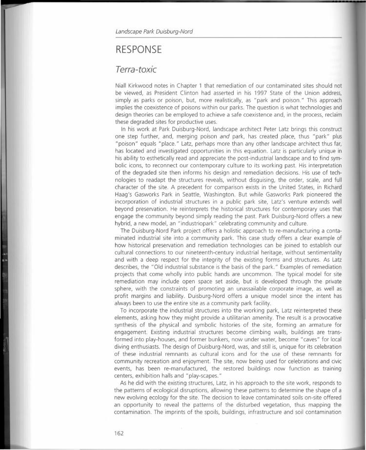
Landscape Park Ouisburg-Nord
RESPONSE
Terra-toxic
Niall Kirkwood notes in Chapter 1 that remediation of our contaminated sites should notbe viewed, as President Clinton had asserted in his 1997 State of the Union address,
simply as parks or poison, but, more realistically, as "park and poison." This approachimplies the coexistence of poisons within our parks. The question is what technologies anddesign theories can be employed to achieve a safe coexistence and, in the process, reclaimthese degraded sites for productive uses.
In his work at Park Duisburg-Nord, landscape architect Peter Latz brings this constructone step further, and, merging poison and park, has created place, thus "park" plus"poison" equals "place." Latz, perhaps more than any other landscape architect thus far,has located and investigated opportunities in this equation. Latz is particularly unique inhis ability to esthetically read and appreciate the post-industrial landscape and to find symbolic icons, to reconnect our contemporary culture to its working past. His interpretationof the degraded site then informs his design and remediation decisions. His use of technologies to readapt the structures reveals, without disguising, the order, scale, and fullcharacter of the site. A precedent for comparison exists in the United States, in RichardHaag's Gasworks Park in Seattle, Washington. But while Gasworks Park pioneered theincorporation of industrial structures in a public park site, Latz's venture extends wellbeyond preservation. He reinterprets the historical structures for contemporary uses thatengage the community beyond simply reading the past. Park Duisburg-Nord offers a newhybrid, a new model, an "industriopark" celebrating community and culture.
The Duisburg-Nord Park project offers a holistic approach to re-manufacturing a contaminated industrial site into a community park. This case study offers a clear example ofhow historical preservation and remediation technologies can be joined to establish ourcultural connections to our nineteenth-century industrial heritage, without sentimentalityand with a deep respect for the integrity of the existing forms and structures. As Latzdescribes, the "Old industrial substance is the basis of the park." Examples of remediationprojects that come wholly into public hands are uncommon. The typical model for siteremediation may include open space set aside, but is developed through the privatesphere, with the constraints of promoting an unassailable corporate image, as well asprofit margins and liability. Duisburg-Nord offers a unique model since the intent hasalways been to use the entire site as a community park facility.
To incorporate the industrial structures into the working park, Latz reinterpreted theseelements, asking how they might provide a utilitarian amenity. The result is a provocativesynthesis of the physical and symbolic histories of the site, forming an armature forengagement. Existing industrial structures become climbing walls, buildings are transformed into play-houses, and former bunkers, now under water, become "caves" for localdiving enthusiasts. The design of Duisburg-Nord, was, and still is, unique for its celebrationof these industrial remnants as cultural icons and for the use of these remnants for
community recreation and enjoyment. The site, now being used for celebrations and civicevents, has been re-manufactured, the restored buildings now function as trainingcenters, exhibition halls and "play-scapes."
As he did with the existing structures, Latz, in his approach to the site work, responds tothe patterns of ecological disruptions, allowing these patterns to determine the shape of anew evolving ecology for the site. The decision to leave contaminated soils on-site offeredan opportunity to reveal the patterns of the disturbed vegetation, thus mapping thecontamination. The imprints of the spoils, buildings, infrastructure and soil contamination
162
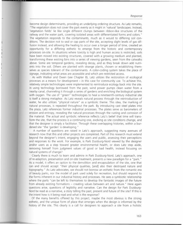
t
Response
become design determinants, providing an underlying ordering structure. As Latz remarks,"The vegetation does not cover the park evenly as it might in 'natural' landscapes. Instead,'vegetation fields' lie like single different clumps between ribbon-like structures of therailway and the water park, covering isolated areas with differentiated forms and colors."The vegetation responds to the contaminants, much as it would to differing soil conditions. The decision not to seal or cap parts of the site, accepting slight levels of gas diffusion instead, and allowing the healing to occur over a longer period of time, created anopportunity for a differing esthetic to emerge from the historic and contemporaryprocesses on-site. In situations where toxicity is high and human access is restricted, soilshave been moved into existing structures, covered with a growing medium and planted,transforming these existing bins into a series of viewing gardens, seen from the catwalksabove. Some are temporal gardens, revealing decay, and as they break down add nutrients into the soil. Others are planted with strange plants, chosen or establishing themselves as species tolerant of the contaminants. A color-coding system takes the place ofsignage, indicating what areas are accessible and which are restricted access.
As with Walker and Owen (see Chapter 8), Latz utilizes the restoration of ecologicalprocesses as a means for development - in this case for community use. To achieve this,relatively simple technologies were implemented to reintroduce ecology back into the site.In using technology borrowed from the past, wind power pumps clean water from anearby canal, channeling it through a series of gardens and enriching the biological systemwith oxygen. The use of "green" technologies to heal a nineteenth-century industrial siteis itself a strong metaphor. As Latz reveals natural process through the reintroduction ofwater, he also utilizes "physical nature" as a symbolic theme. This idea, the marking ofnatural processes, is repeated throughout the park. By introducing cast steel plates intothe plaza, Latz references former industrial processes. The plates serve as barometers oferosion and entropy, revealing the natural processes through the rusting and corrosion ofthe material. The actual and symbolic reference reflects Latz's belief that time will transform the site, that the process is a continuing one, evolving as site conditions change, andthat the designer is simply a facilitator. Through these overlapping histories, within a burdened site "the 'garden' is developing."
A number of questions are raised in Latz's approach, suggesting many avenues ofresearch now that this and other projects are completed. Part of this research must extendbeyond the designer's intent, engaging the users and public, assessing their perceptionsand responses to the work. For example, is Park Duisburg-Nord viewed by the designerand/or users as a step toward greater environmental health, or does Latz step aside,removing himself from judgment values of good or bad health, instead focusing onnatural systems of change?
Clearly there is much to learn and admire in Park Duisburg-Nord. Latz's approach, oneof re-adaption, preservation and on-site treatment, presents a new paradigm for a "park."As a model, it offers an option to the demolition and encapsulation of the site, one thatcan and should accept "their physical qualities, [and] also their destroyed nature andtopography." As Latz advocates, we should not borrow an esthetic from the romantic eraof beauty parks, nor the model of park used solely for recreation, but should respond tothe forms inherent in our industrial history and processes. He sees a symbiotic relationshipwhere the parts "can be left to themselves to develop the fantastic images of the futurefrom already existing formations - creating values between art and nature." Here againquestions arise, questions of legibility and narrative. Can the design for Park DuisburgNord be read as a narrative, a story telling the past, present and future of the site? If this isthe intent how is it being read and what is the response?
Of the many benefits offered by this project, maybe the most obvious is the strongesthetic, and the unique form of place that emerges when the design is informed by thehistory of the site. This clearly is a call for designers to approach a site from a holistic
163
Landscape Park Ouisburg-Nord
vantage point, one that sees the layering of benefits as a part of site remediation. Itis clearly an approach that challenges the skills of designers and their ability to establisha meaningful design, provide a community benefit, and redress the toxic nature of thesite.
As a model of reuse, it has the added benefit of less traffic and hauling from the site,resulting in reduced negative impacts on the surrounding communities. By minimizingdemolition, the potential for dust-borne toxins is reduced, and demolition costs saved. Inusing existing structures such as the containment bins, excavation costs have been saved.Is this a model that can be used at other sites? There were several unique opportunitiesexisting in this site that may not be found in other situations; however, many of the strategies offered in this project may be incorporated, in part, at other sites.
To accomplish Duisburg-Nord, an engaged community providing strong support wascritical to the success of the project. A population density within close proximity to the siteis necessary to justify recreational programmatic elements. Access to and maintenance ofthe site and organized activity planning are also critical components to ensure year-rounduse. The same level of support from the municipality, state and counties is critical in boththe developmental and the post-construction stages.
Is this model possible in the United States? As McNeil and Lange points out in Chapter6, "Environmental regulations and liability are generally regarded as the single mostsignificant deterrent to site development." And in a project such as Duisburg-Nord, thelong time-frame, the on-site gas diffusion a,ld the focus of people engaged with the landall raise legal and liability issues that, while not insurmountable, would have to be negotiated through local codes. However, with more recent legislation geared toward settingclean-up criteria to be consistent with intended use, some latitude may exist to allow thesealternate uses to be incorporated in future remediation projects in this country.
In reviewing Park Duisburg-Nord, questions of cultural differences arise. Latz states thatin the end the "fear of historical contamination has given way to a calm acceptance of thestructures." What was the nature of public trust in the authorities to ensure that a healthyhabitat for recreating was in fact possible? How did Latz and/or the authorities gain thispublic trust and is the site periodically monitored to alleviate any current or future publicfears? Can design itself really overcome public paranoia or is outreach and public education an essential component of this type of remediation? Are there differences betweenthe German and the American public in their reliance and trust in the public authorities?Many Americans have prevailing negative associations with clean-up sites from Love Canalin the 1960s to the Hanford nuclear site which continues. After gathering new data thatindicates the environmental health risks at Gasworks Park have not been properly resolvedthe site is being re-evaluated. One of the most pervasive issues stemming from thisprocess are the difficulties in finding public consensus on how to address the problem,and, for the public, which of the varying scientific authorities to align with. The re-examination of the safety issues, particularly soil contamination and safe play, has spawnedmany contentious public meetings, indicating that a cloud of continuing reassurancehangs over the concept of site remediaition for public parks.
A project such as Duisburg-Nord may not be possible in a privately funded projectwhere the return on investment is calculated in currency, and housing, office space andretail are critical to the economics of a project. However, this model may present someoptions where adaptive reuse of the structures, revealing of the natural and technologicalprocesses, and the utilization of the site for recreational use may provide a greater returnat less cost.
Finally, does this project offer some technologies that should or can be adopted in otherprojects?
Park Duisburg-Nord provides a bridge, one that borrows from earlier attempts at preservation, utilizes remediation technologies, and offers an inclusive process that brings
164

Response
community members, public sector administrators and a diversity of professionals to thesame table, where each is heard and their values and ideas incorporated into the project.This project, from a design and community development point of view, offers a challenging model for further exploration and research in the re-manufacturing of damaged sites.
165
Chapter 12
Science, engineering, and the artof restoration:two case studies in wetland construction
Wendi Goldsmith
Introduction
Landscape architects are faced with many opportunities to integrate esthetic design withhuman use, enjoyment, and education as well as stewardship of the natural environment.Virtually every site under development must also address issues related to stormwatermanagement, whether by legal mandate or simply for practical reasons. Management ofwater on-site can be handled with conventional, ugly, and single-minded treatmentsexemplified by the traditional rock-lined detention basin with a chain-link fence around it,or through attractive landscape water features which invite contemplation while promoting wildlife habitat and water quality.
Past and current land-use activities typically contribute to degradation of the qualities ofa natural resource by displacing native plants and site-adapted soils, upsetting the hydrologic balance of the watershed, fragmenting and disconnecting remaining adjacenthabitat features, and generally introducing contamination in forms ranging from excessnutrients to the dumping of industrial waste. A responsible land ethic requires stewardshipthat includes restoration of past damage while avoiding continuing degradation. The legalcosts of addressing wetland, stream and stormwater issues already form a considerableburden to public and private interests. By working in collaboration with natural scientists,resource managers, and engineers, today's landscape architects can design projects thatrestore natural ecological functions in degraded riparian areas.
In this essay, two case studies are presented and discussed as examples of landscapedesign that integrates resource restoration with site planning. The first, located at theFederal Medical Center in Devens, Massachusetts, shows the potential for biologicalenhancement of a utilitarian stormwater system. The second, a wetland restoration inVinalhaven, Maine, describes the potential for re-creating severely altered tidal marshland.This second project represents an innovative collaboration between The BioengineeringGroup of Salem, Massachusetts and Aviva Rahmani, an environmental artist.
1 Federal Medical Center, Devens, Massachusetts
A bioengineered pond and wetland system, located on the site of a decommissioned armybase at the Bureau of Prisons Medical Center in Devens, successfully combines stormwaterquality and discharge control with ecological enhancement. The project created threeinterconnected, heavily vegetated basins along an existing stream course to improve water
166
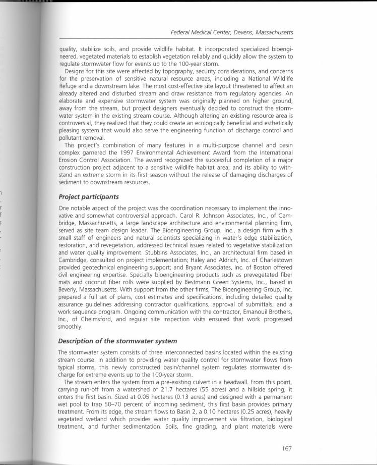
Federal Medical Center, Devens, Massachusetts
quality, stabilize soils, and provide wildlife habitat. It incorporated specialized bioengineered, vegetated materials to establish vegetation reliably and quickly allow the system toregulate stormwater flow for events up to the 1OO-yearstorm.
Designs for this site were affected by topography, security considerations, and concernsfor the preservation of sensitive natural resource areas, including a National WildlifeRefuge and a downstream lake. The most cost-effective site layout threatened to affect analready altered and disturbed stream and draw resistance from regulatory agencies. Anelaborate and expensive stormwater system was originally planned on higher ground,away from the stream, but project designers eventually decided to construct the stormwater system in the existing stream course. Although altering an existing resource area iscontroversial, they realized that they could create an ecologically beneficial and estheticallypleasing system that would also serve the engineering function of discharge control andpollutant removal.
This project's combination of many features in a multi-purpose channel and basincomplex garnered the 1997 Environmental Achievement Award from the InternationalErosion Control Association. The award recognized the successful completion of a majorconstruction project adjacent to a sensitive wildlife habitat area, and its ability to withstand an extreme storm in its first season without the release of damaging discharges ofsediment to downstream resources.
Project participants
One notable aspect of the project was the coordination necessary to implement the innovative and somewhat controversial approach. Carol R. Johnson Associates, Inc., of Cambridge, Massachusetts, a large landscape architecture and environmental planning firm,served as site team design leader. The Bioengineering Group, Inc., a design firm with asmall staff of engineers and natural scientists specializing in water's edge stabilization,restoration, and revegetation, addressed technical issues related to vegetative stabilizationand water quality improvement. Stubbins Associates, Inc., an architectural firm based inCambridge, consulted on project implementation; Haley and Aldrich, Inc. of Charlestownprovided geotechnical engineering support; and Bryant Associates, Inc. of Boston offeredcivil engineering expertise. Specialty bioengineering products such as prevegetated fibermats and coconut fiber rolls were supplied by Bestmann Green Systems, Inc., based inBeverly, Massachusetts. With support from the other firms, The Bioengineering Group, Inc.prepared a full set of plans, cost estimates and specifications, including detailed qualityassurance guidelines addressing contractor qualifications, approval of submittals, and awork sequence program. Ongoing communication with the contractor, Emanouil Brothers,Inc., of Chelmsford, and regular site inspection visits ensured that work progressedsmoothly.
Description of the storm water system
The stormwater system consists of three interconnected basins located within the existingstream course. In addition to providing water quality control for stormwater flows fromtypical storms, this newly constructed basin/channel system regulates stormwater discharge for extreme events up to the 1OO-yearstorm.
The stream enters the system from a pre-existing culvert in a headwall. From this point,carrying run-off from a watershed of 21.7 hectares (55 acres) and a hillside spring, itenters the first basin. Sized at 0.05 hectares (0.13 acres) and designed with a permanentwet pool to trap 50-70 percent of incoming sediment, this first basin provides primarytreatment. From its edge, the stream flows to Basin 2, a 0.10 hectares (0.25 acres), heavilyvegetated wetland which provides water quality improvement via filtration, biologicaltreatment, and further sedimentation. Soils, fine grading, and plant materials were
167
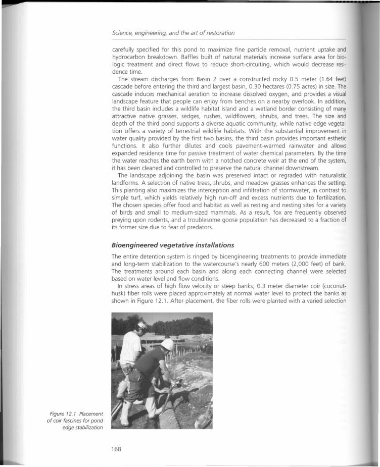
Figure 12. 1 Placement
of coir fascines for pondedge stabilization
Science, engineering, and the art of restoration
carefully specified for this pond to maximize fine particle removal, nutrient uptake andhydrocarbon breakdown. Baffles built of natural materials increase surface area for biologic treatment and direct flows to reduce short-circuiting, which would decrease residence time.
The stream discharges from Basin 2 over a constructed rocky 0.5 meter (1.64 feet)cascade before entering the third and largest basin, 0.30 hectares (0.75 acres) in size. Thecascade induces mechanical aeration to increase dissolved oxygen, and provides a visuallandscape feature that people can enjoy from benches on a nearby overlook. In addition,the third basin includes a wildlife habitat island and a wetland border consisting of manyattractive native grasses, sedges, rushes, wildflowers, shrubs, and trees. The size anddepth of the third pond supports a diverse aquatic community, while native edge vegetation offers a variety of terrestrial wildlife habitats. With the substantial improvement inwater quality provided by the first two basins, the third basin provides important estheticfunctions. It also further dilutes and cools pavement-warmed rainwater and allowsexpanded residence time for passive treatment of water chemical parameters. By the timethe water reaches the earth berm with a notched concrete weir at the end of the system,it has been cleaned and controlled to preserve the natural channel downstream.
The landscape adjoining the basin was preserved intact or regraded with naturalisticlandforms. A selection of native trees, shrubs, and meadow grasses enhances the setting.This planting also maximizes the interception and infiltration of stormwater, in contrast tosimple turf, which yields relatively high run-off and excess nutrients due to fertilization.The chosen species offer food and habitat as well as resting and nesting sites for a varietyof birds and small to medium-sized mammals. As a result, fox are frequently observedpreying upon rodents, and a troublesome goose population has decreased to a fraction ofits former size due to fear of predators.
Bioengineered vegetative installations
The entire detention system is ringed by bioengineering treatments to provide immediateand long-term stabilization to the watercourse's nearly 600 meters (2,000 feet) of bank.The treatments around each basin and along each connecting channel were selectedbased on water level and flow conditions.
In stress areas of high flow velocity or steep banks, 0.3 meter diameter coir (coconuthusk) fiber rolls were placed approximately at normal water level to protect the banks asshown in Figure 12.1. After placement, the fiber rolls were planted with a varied selection
168
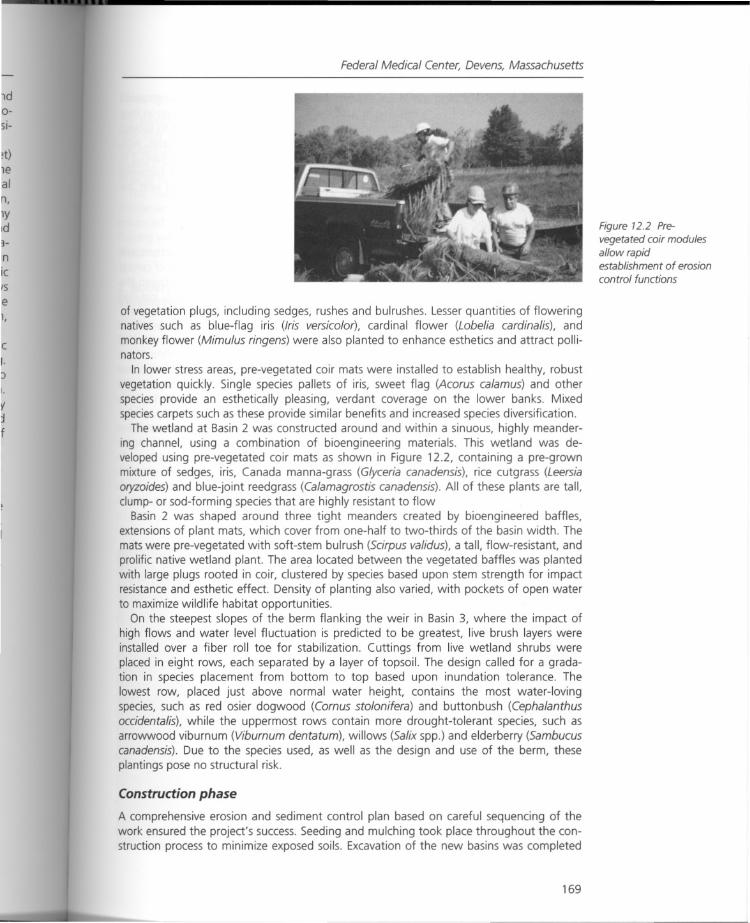
Federal Medical Center, Devens, Massachusetts
of vegetation plugs, including sedges, rushes and bulrushes. Lesser quantities of floweringnatives such as blue-flag iris (Iris versicolor), cardinal flower (Lobelia cardinalis), andmonkey flower (Mimulus ringens) were also planted to enhance esthetics and attract pollinators.
In lower stress areas, pre-vegetated coir mats were installed to establish healthy, robustvegetation quickly. Single species pallets of iris, sweet flag (Acarus calamus) and otherspecies provide an esthetically pleasing, verdant coverage on the lower banks. Mixedspeciescarpets such as these provide similar benefits and increased species diversification.
The wetland at Basin 2 was constructed around and within a sinuous, highly meandering channel, using a combination of bioengineering materials. This wetland was developed using pre-vegetated coir mats as shown in Figure 12.2, containing a pre-grownmixture of sedges, iris, Canada manna-grass (Glyceria canadensis), rice cutgrass (Leersiaoryzoides) and blue-joint reedgrass (Calamagrostis canadensis). All of these plants are tall,c1ump-or sod-forming species that are highly resistant to flow
Basin 2 was shaped around three tight meanders created by bioengineered baffles,extensions of plant mats, which cover from one-half to two-thirds of the basin width. Themats were pre-vegetated with soft-stem bulrush (Scirpus validus), a tall, flow-resistant, andprolific native wetland plant. The area located between the vegetated baffles was plantedwith large plugs rooted in coir, clustered by species based upon stem strength for impactresistance and esthetic effect. Density of planting also varied, with pockets of open waterto maximize wildlife habitat opportunities.
On the steepest slopes of the berm flanking the weir in Basin 3, where the impact ofhigh flows and water level fluctuation is predicted to be greatest, live brush layers wereinstalled over a fiber roll toe for stabilization. Cuttings from live wetland shrubs wereplaced in eight rows, each separated by a layer of topsoil. The design called for a gradation in species placement from bottom to top based upon inundation tolerance. Thelowest row, placed just above normal water height, contains the most water-lovingspecies, such as red osier dogwood (Comus stolonifera) and button bush (Cephalanthusoccidentalis), while the uppermost rows contain more drought-tolerant species, such asarrowwood viburnum (Viburnum dentatum), willows (Salix spp.) and elderberry (Sambucuscanadensis). Due to the species used, as well as the design and use of the berm, theseplantings pose no structural risk.
Construction phase
A comprehensive erosion and sediment control plan based on careful sequencing of thework ensured the project's success. Seeding and mulching took place throughout the construction process to minimize exposed soils. Excavation of the new basins was completed
169
Figure 72.2 Pre
vegetated coir modulesallow rapidestablishment of erosioncontrol functions
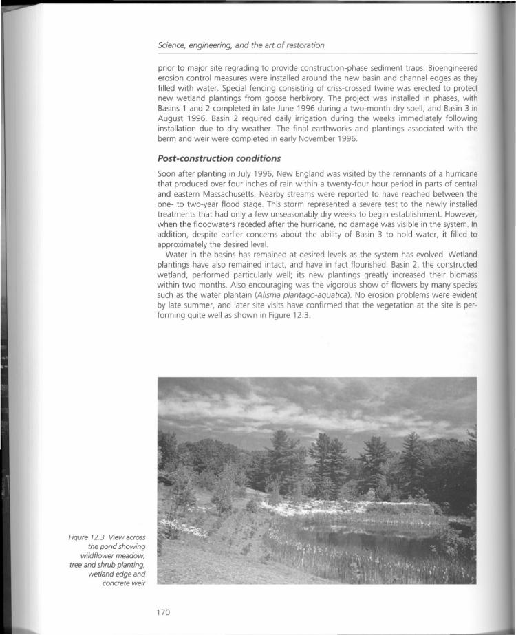
Figure 12.3 View across
the pond showingwildflower meadow,
tree and shrub planting,wetland edge and
concrete weir
Science, engineering, and the art of restoration
prior to major site regrading to provide construction-phase sediment traps. Bioengineerederosion control measures were installed around the new basin and channel edges as theyfilled with water. Special fencing consisting of criss-crossed twine was erected to protectnew wetland plantings from goose herbivory. The project was installed in phases, withBasins 1 and 2 completed in late June 1996 during a two-month dry spell, and Basin 3 inAugust 1996. Basin 2 required daily irrigation during the weeks immediately followinginstallation due to dry weather. The final earthworks and plantings associated with theberm and weir were completed in early November 1996.
Post-construction conditions
Soon after planting in July 1996, New England was visited by the remnants of a hurricanethat produced over four inches of rain within a twenty-four hour period in parts of centraland eastern Massachusetts. Nearby streams were reported to have reached between theone- to two-year flood stage. This storm represented a severe test to the newly installedtreatments that had only a few unseasonably dry weeks to begin establishment. However,when the floodwaters receded after the hurricane, no damage was visible in the system. Inaddition, despite earlier concerns about the ability of Basin 3 to hold water, it filled toapproximately the desired level.
Water in the basins has remained at desired levels as the system has evolved. Wetlandplantings have also remained intact, and have in fact flourished. Basin 2, the constructedwetland, performed particularly well; its new plantings greatly increased their biomasswithin two months. Also encouraging was the vigorous show of flowers by many speciessuch as the water plantain (Alisma plantago-aquatica). No erosion problems were evidentby late summer, and later site visits have confirmed that the vegetation at the site is performing quite well as shown in Figure 12.3.
170
Roberts Harbor tidal marsh and riparian zone restoration, Vinalhaven, Maine
Closure
The successful design and installation of this stormwater management system was possible only through the collaboration and partnership of the design team and, ultimately,the contractor. Design team members recognized the opportunity for integrating waterquality control and flow detention with esthetic and ecological benefits, and were willingto work to implement this innovative approach.
The result is a highly functional system from an engineering perspective, with lowermaintenance costs than conventional facilities and plantings. The site is also greatlyenhanced by natural beauty that changes with the seasons; the sight and sound offlowing water and wildlife, visible evidence of the protection of water quality during andafter construction, demonstrate the project's effectiveness.
2 Roberts Harbor tidal marsh and riparian zone restoration,Vinalhaven, Maine
In 1990 Aviva Rahmani, an environmental artist, purchased a parcel of a former quarry atRoberts Harbor on the island of Vinalhaven, Maine, for the purpose of reclamation. Onceburied under tons of quarried granite, the site had long since lost its cover of native vegetation and undergone dramatic changes in soil structure and hydrological conditions. MsRahmani took it upon herself to restore the drainage patterns, improve soil fertility, andplant communities that had once thrived there.
After several years of aggressive compost application and transplantation of nativeseedlings and garden plants, the barren rock-strewn uplands adjacent to the shorelinemarsh showed signs of new life. Ms Rahmani then turned her attention to the restorationof an intermittent stream channel, buried under hundreds of tons of quarry waste, whichdrains to the marsh. She drew inspiration from a pocket of native vegetation that had survived despite the extensive damage. Located between upland ecosystems and coastal tidalmarshland, this channel plays an important ecological role. It creates linkage for a Class Amigratory bird fly zone, and ensures the health of local ecosystems by controlling watertransport.
The Bioengineering Group has been an ongoing partner for this project since 1994.Responsible for project design, consulting, and engineering, it has used state-of-the-artbioengineering techniques, including placement of coir rolls and fabric, to stabilize plantings of native grasses and other vegetation to re-establish natural plant communities.
Introduction and site description
Despite its apparent isolation, Vinalhaven Island played a role in the development of NorthAmerica, and shows the scars of industrial impact. Rock from Oatmeal Quarry, lying adjacent to the marsh, was used in the construction and architectural detail of many notablebuildings and structures, including the Cathedral of Saint John the Divine in New York, theSaint Louis Post Office, and piers for the Brooklyn Bridge. During the peak years of excavation, the marsh site was buried under thousands of tons of granite blocks, small granitechips from shaping, coal and slag from "burning out" the rock, and even rails from thefreight car system used to haul quarried rock to the stone pier that still juts into theharbor. It had also been used in recent years as the town dump.
Research showed that salt marsh conditions were present at Roberts Harbor prior to disturbances caused by extensive quarrying. Numerous clumps of salt marsh vegetationexisted on the 0.1 hectare (0.25 acre) site, literally peeking out from under granite blocks,including smooth cordgrass (Spartina a/temif/ora), salt meadow grass (Spartina patens)and black grass (Juncus gerardil). The presence of these species indicated that the proposed project was a restoration of natural conditions, and that the area could support the
171
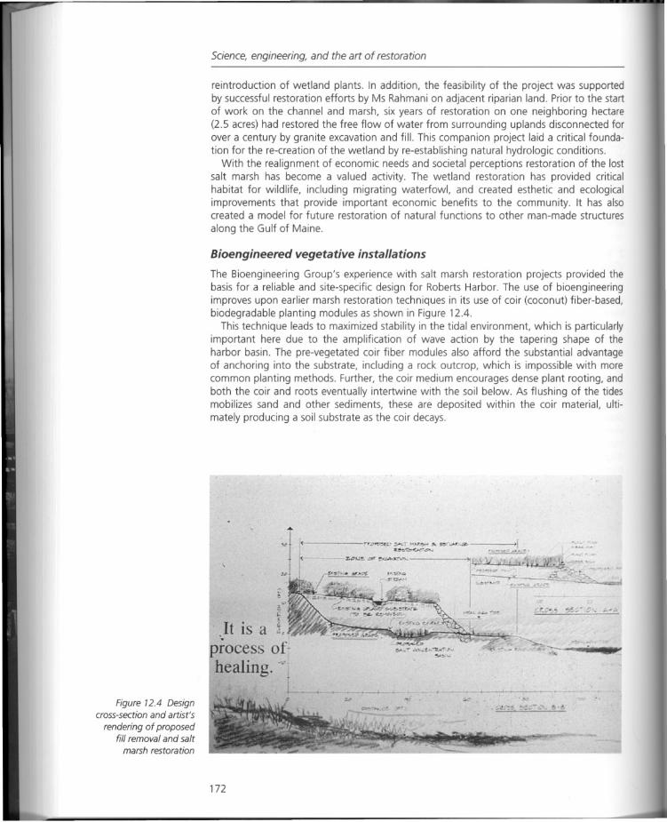
Figure 12.4 Designcross-section and artist's
rendering of proposedfill removal and salt
marsh restoration
Science, engineering, and the art of restoration
reintroduction of wetland plants. In addition, the feasibility of the project was supportedby successful restoration efforts by Ms Rahmani on adjacent riparian land. Prior to the startof work on the channel and marsh, six years of restoration on one neighboring hectare(2.5 acres) had restored the free flow of water from surrounding uplands disconnected forover a century by granite excavation and fill. This companion project laid a critical foundation for the re-creation of the wetland by re-establishing natural hydrologic conditions.
With the realignment of economic needs and societal perceptions restoration of the lostsalt marsh has become a valued activity. The wetland restoration has provided criticalhabitat for wildlife, including migrating waterfowl, and created esthetic and ecologicalimprovements that provide important economic benefits to the community. It has alsocreated a model for future restoration of natural functions to other man-made structures
along the Gulf of Maine.
Bioengineered vegetative installations
The Bioengineering Group's experience with salt marsh restoration projects provided thebasis for a reliable and site-specific design for Roberts Harbor. The use of bioengineeringimproves upon earlier marsh restoration techniques in its use of coir (coconut) fiber-based,biodegradable planting modules as shown in Figure 12.4.
This technique leads to maximized stability in the tidal environment, which is particularlyimportant here due to the amplification of wave action by the tapering shape of theharbor basin. The pre-vegetated coir fiber modules also afford the substantial advantageof anchoring into the substrate, including a rock outcrop, which is impossible with morecommon planting methods. Further, the coir medium encourages dense plant rooting, andboth the coir and roots eventually intertwine with the soil below. As flushing of the tidesmobilizes sand and other sediments, these are deposited within the coir material, ultimately producing a soil substrate as the coir decays.
<------I,.r.D~ .,..._.,..•..N~ ;,.,0.' •••••• -- _ _>L-~~~
z."U~t:;IfS~-_"'_
.It i arace s of
healing .....
172
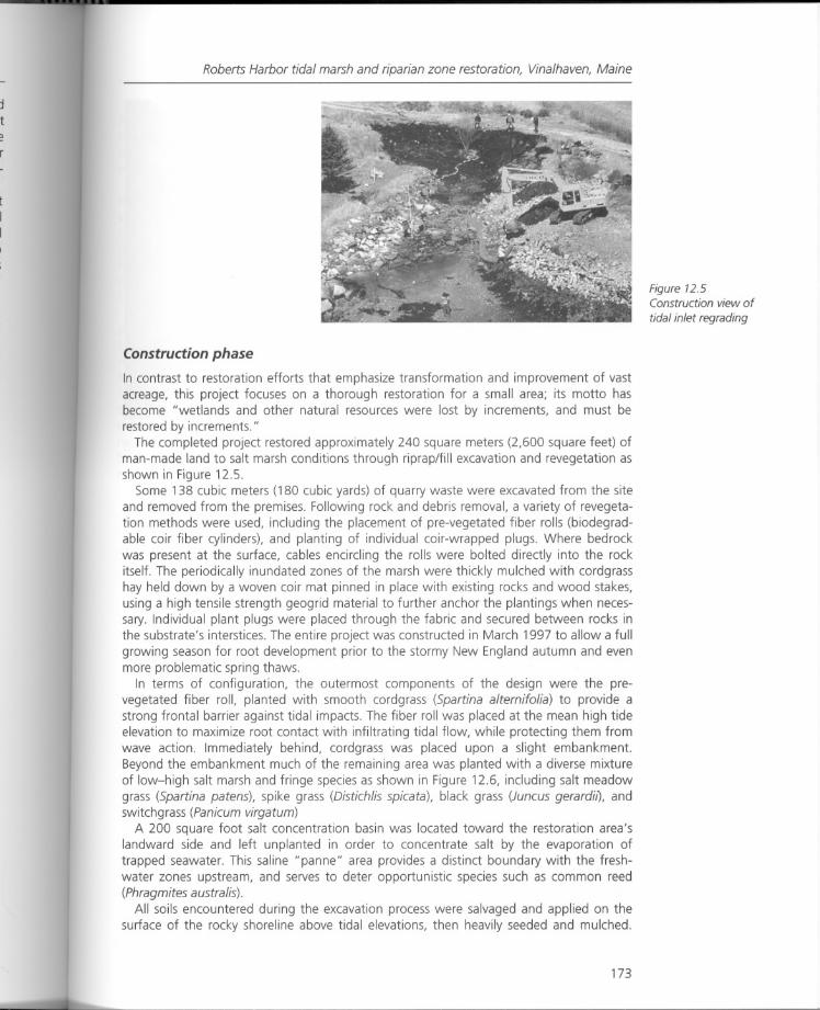
Roberts Harbor tidal marsh and riparian zone restoration, Vinalhaven, Maine
Construction phase
In contrast to restoration efforts that emphasize transformation and improvement of vastacreage, this project focuses on a thorough restoration for a small area; its motto hasbecome "wetlands and other natural resources were lost by increments, and must berestored by increments."
The completed project restored approximately 240 square meters (2,600 square feet) ofman-made land to salt marsh conditions through riprap/fill excavation and revegetation asshown in Figure 12.5.
Some 138 cubic meters (180 cubic yards) of quarry waste were excavated from the siteand removed from the premises. Following rock and debris removal, a variety of revegetation methods were used, including the placement of pre-vegetated fiber rolls (biodegradable coir fiber cylinders), and planting of individual coir-wrapped plugs. Where bedrockwas present at the surface, cables encircling the rolls were bolted directly into the rockitself. The periodically inundated zones of the marsh were thickly mulched with cordgrasshay held down by a woven coir mat pinned in place with existing rocks and wood stakes,using a high tensile strength geogrid material to further anchor the plantings when necessary. Individual plant plugs were placed through the fabric and secured between rocks inthe substrate's interstices. The entire project was constructed in March 1997 to allow a fullgrowing season for root development prior to the stormy New England autumn and evenmore problematic spring thaws.
In terms of configuration, the outermost components of the design were the prevegetated fiber roll, planted with smooth cordgrass (Spartina alternifolia) to provide astrong frontal barrier against tidal impacts. The fiber roll was placed at the mean high tideelevation to maximize root contact with infiltrating tidal flow, while protecting them fromwave action. Immediately behind, cordgrass was placed upon a slight embankment.Beyond the embankment much of the remaining area was planted with a diverse mixtureof low-high salt marsh and fringe species as shown in Figure 12.6, including salt meadowgrass (Spartina patens), spike grass (Distich lis spicata), black grass (Juncus gerardil), andswitchgrass (Panicum virgatum)
A 200 square foot salt concentration basin was located toward the restoration area'slandward side and left unplanted in order to concentrate salt by the evaporation oftrapped seawater. This saline "panne" area provides a distinct boundary with the freshwater zones upstream, and serves to deter opportunistic species such as common reed(Phragmites australis).
All soils encountered during the excavation process were salvaged and applied on thesurface of the rocky shoreline above tidal elevations, then heavily seeded and mulched.
173
Figure 12.5Construction view of
tidal inlet regrading
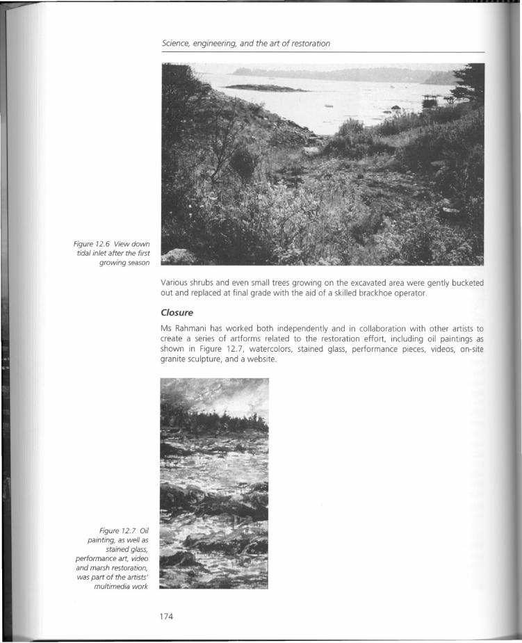
Figure 12.6 View downtidal inlet after the first
growing season
Figure 12.7 Oil
painting, as well asstained glass,
performance art, videoand marsh restoration,
was part of the artists'multimedia work
Science, engineering, and the art of restoration
Various shrubs and even small trees growing on the excavated area were gently bucketedout and replaced at final grade with the aid of a skilled brackhoe operator.
Closure
Ms Rahmani has worked both independently and in collaboration with other artists tocreate a series of artforms related to the restoration effort, including oil paintings asshown in Figure 12.7, watercolors, stained glass, performance pieces, videos, on-sitegranite sculpture, and a website.
174
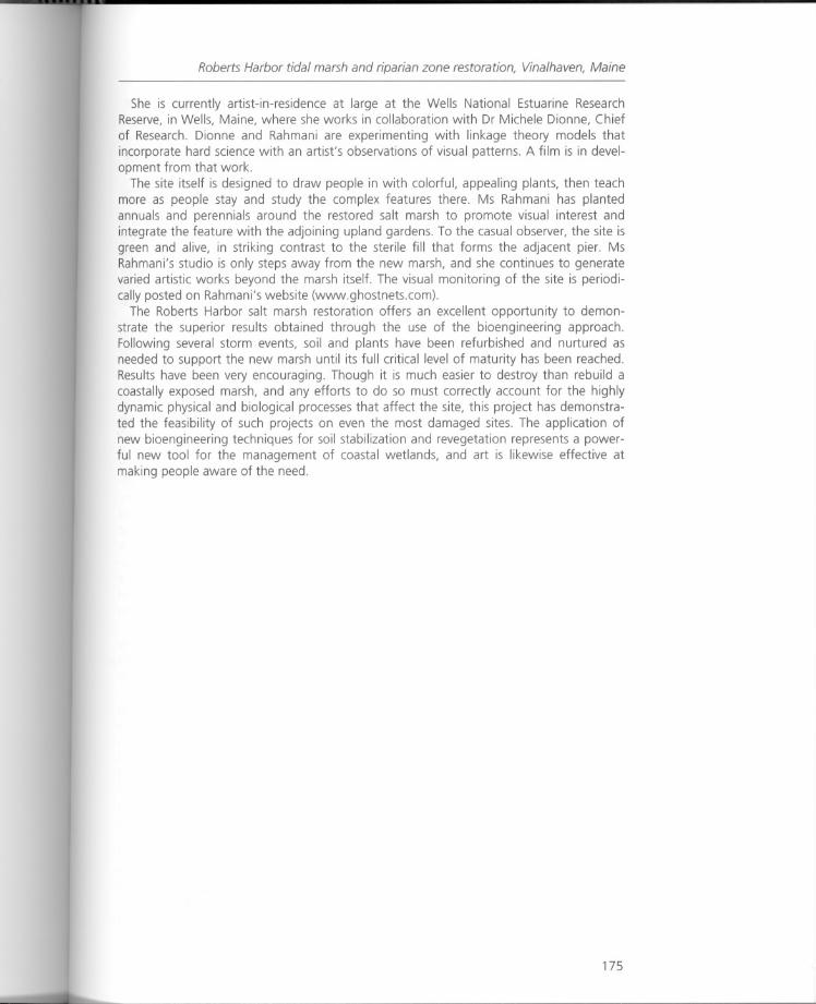
Roberts Harbor tidal marsh and riparian zone restoration, Vinalhaven, Maine
She is currently artist-in-residence at large at the Wells National Estuarine ResearchReserve, in Wells, Maine, where she works in collaboration with Dr Michele Dionne, Chiefof Research. Dionne and Rahmani are experimenting with linkage theory models thatincorporate hard science with an artist's observations of visual patterns. A film is in development from that work.
The site itself is designed to draw people in with colorful, appealing plants, then teachmore as people stay and study the complex features there. Ms Rahmani has plantedannuals and perennials around the restored salt marsh to promote visual interest andintegrate the feature with the adjoining upland gardens. To the casual observer, the site isgreen and alive, in striking contrast to the sterile fill that forms the adjacent pier. MsRahmani's studio is only steps away from the new marsh, and she continues to generatevaried artistic works beyond the marsh itself. The visual monitoring of the site is periodically posted on Rahmani's website (www.ghostnets.com).
The Roberts Harbor salt marsh restoration offers an excellent opportunity to demonstrate the superior results obtained through the use of the bioengineering approach.Following several storm events, soil and plants have been refurbished and nurtured asneeded to support the new marsh until its full critical level of maturity has been reached.Results have been very encouraging. Though it is much easier to destroy than rebuild acoastally exposed marsh, and any efforts to do so must correctly account for the highlydynamic physical and biological processes that affect the site, this project has demonstrated the feasibility of such projects on even the most damaged sites. The application ofnew bioengineering techniques for soil stabilization and revegetation represents a powerful new tool for the management of coastal wetlands, and art is likewise effective atmaking people aware of the need.
175
Science, engineering, and the art of restoration
RESPONSE
More bio than engineering?
The description that follows lays out the underpinnings of the work carried out by WendiGoldsmith and her colleagues in bioengineering and landscape restoration design.
"Bioengineering" is an approach to erosion control, bank stabilization, wetlandrestoration, water quality improvement, and habitat enhancement, which uses livingplants, and organic structural elements and materials as basic construction modules. Theterm "bioengineering" describes several methods of establishing vegetative cover byembedding a combination of live, dormant and/or decaying plant materials into banksand shorelines. Variations of the term are also in use, including "biotechnical slopeprotection, " "biogeotechnical erosion control," "soil bioengineering" and "hydrobioengineering"; these terms sometimes further differentiate sub-fields of bioengineeringor differentiate it from the unrelated fields of biomedical technology and geneticengineering.
Bioengineering systems work together with the dynamic processes of erosion and sedimentation along the bank or shoreline to provide ongoing stability, starting at the time ofinstallation. These systems generally employ mechanical components made of biodegradable material, sometimes reinforced with synthetic materials. The use of "hard" barrierssuch as rock is held to a practical minimum, with the design purpose being to establish avigorous, sustainable native or naturalized plant community as the primary erosion controlmechanism. Bioengineering provides all the benefits of vegetation more quickly and reliably than conventional planting techniques. These benefits include bank stabilization,habitat enhancement (food and cover sources and temperature control for aquatic andterrestrial animals), purification and filtration of overland run-off, contribution of organicmatter (nourishment) to land and adjacent water bodies, and esthetic improvement. Agreat strength of bioengineering is its flexibility. Bioengineering methods can be used separately or in widely varying combinations to fit the great diversity of conditions to beaddressed. Combined with sound application of principles of lake management or fluvialgeomorphology, bioengineering can serve as a valuable technology in lake and streamrestoration. 1
Of interest to those who address the issues of restoring manufactured sites is the abilityto use a broader series of engineering and design tools, with biodegradable site materialsbeing applied to both clean up contamination (phytoremediation) as well as repair orrestore damaged earthworks, slopes and water systems (soft engineering). The significance of integrating bioengineering as opposed to conventional environmental engineeringtechniques is demonstrated in the two case studies, Devens, Massachusetts and thewetland restoration in Vinalhaven, Maine. The sea-edge project carried out in conjunctionwith environmental artist Aviva Rahmani is possibly unique in terms of its geographicallocation and the impact of the restoration on the "larger physical and biologicalprocesses." However, as Goldsmith explains, the project hinged on "the restoration ofnatural conditions." Questions that arise relate to the restoration of salt marsh plantingsand stabilization techniques and the ability for small project areas such as this to serve aslarger bio-models for regenerative form. What do the issues of scale bring to these "incremental" models; can the same benefits be brought to larger sites with an economy ofcoverage? The case study also demonstrates the ability to include other participants intothe regeneration of manufactured sites. With the exception of artist Mierle Ukeles, mostclosely associated with the Fresh Kills landfill discussed in Chapter 13, and Ms Rahmani,there are few artists working on the sites under discussion in this book. It suggests that
176

Response
there are other avenues of collaboration through which manufactured sites projects canbe engaged.
Note
The BioengineeringGroup Web Site:http://www.bioengineering.com
177
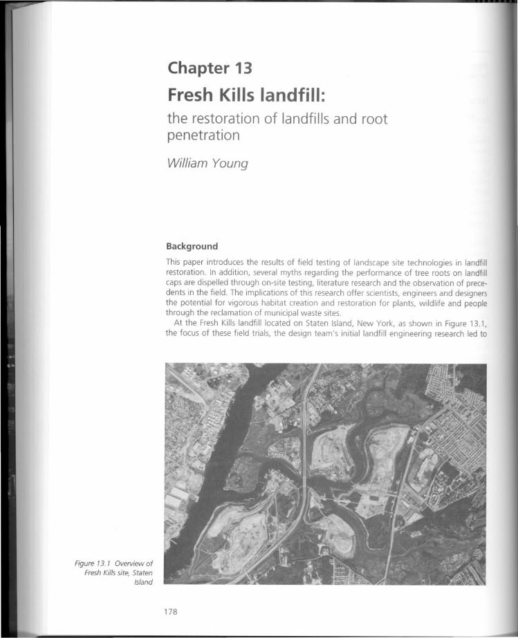
Figure 13. 1 Overview ofFresh Kills site, Staten
Island
Chapter 13
Fresh Kills landfill:the restoration of landfills and root
penetration
William Young
Background
This paper introduces the results of field testing of landscape site technologies in landfillrestoration. In addition, several myths regarding the performance of tree roots on landfillcaps are dispelled through on-site testing, literature research and the observation of precedents in the field. The implications of this research offer scientists, engineers and designersthe potential for vigorous habitat creation and restoration for plants, wildlife and peoplethrough the reclamation of municipal waste sites.
At the Fresh Kills landfill located on Staten Island, New York, as shown in Figure 13.1,the focus of these field trials, the design team's initial landfill engineering research led to
178
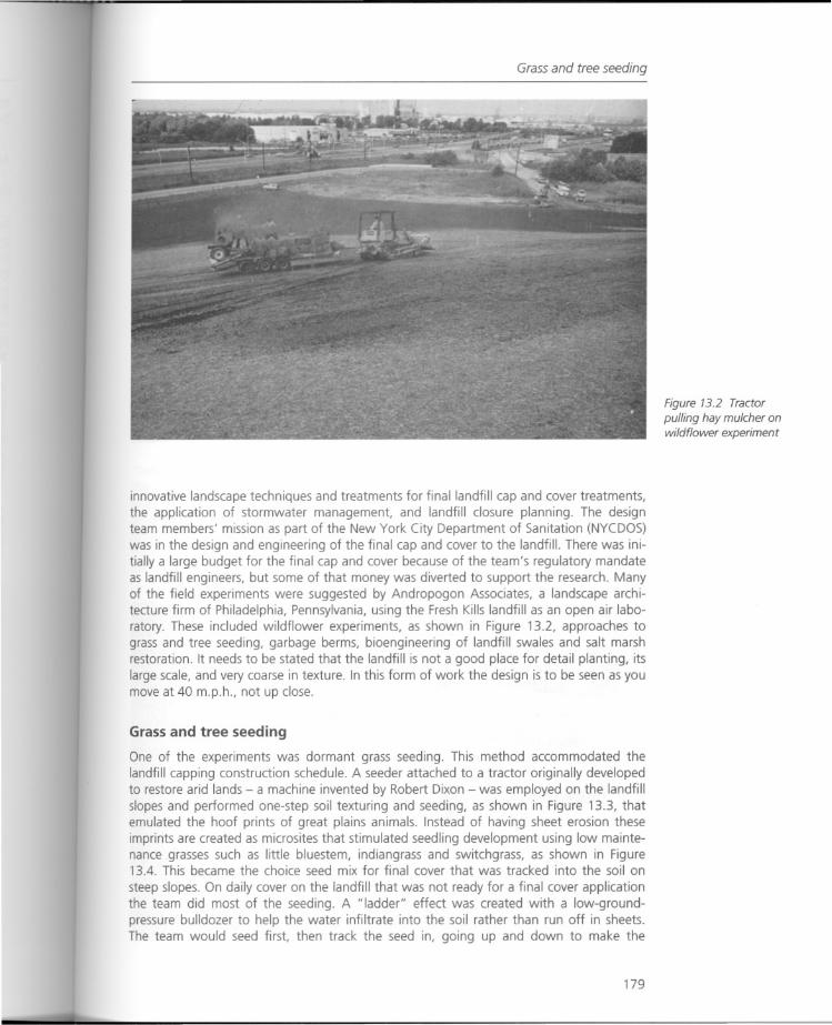
Grass and tree seeding
innovative landscape techniques and treatments for final landfill cap and cover treatments,the application of stormwater management, and landfill closure planning. The designteam members' mission as part of the New York City Department of Sanitation (NYCDOS)was in the design and engineering of the final cap and cover to the landfill. There was initiallya large budget for the final cap and cover because of the team's regulatory mandateas landfill engineers, but some of that money was diverted to support the research. Manyof the field experiments were suggested by Andropogon Associates, a landscape architecture firm of Philadelphia, Pennsylvania, using the Fresh Kills landfill as an open air laboratory. These included wildflower experiments, as shown in Figure 13.2, approaches tograss and tree seeding, garbage berms, bioengineering of landfill swales and salt marshrestoration. It needs to be stated that the landfill is not a good place for detail planting, itslarge scale, and very coarse in texture. In this form of work the design is to be seen as youmove at 40 m.p.h., not up close.
Grass and tree seeding
One of the experiments was dormant grass seeding. This method accommodated thelandfill capping construction schedule. A seeder attached to a tractor originally developedto restore arid lands - a machine invented by Robert Dixon - was employed on the landfillslopes and performed one-step soil texturing and seeding, as shown in Figure 13.3, thatemulated the hoof prints of great plains animals. Instead of having sheet erosion theseimprints are created as microsites that stimulated seedling development using low maintenance grasses such as little bluestem, indiangrass and switchgrass, as shown in Figure13.4. This became the choice seed mix for final cover that was tracked into the soil on
steep slopes. On daily cover on the landfill that was not ready for a final cover applicationthe team did most of the seeding. A "ladder" effect was created with a low-groundpressure bulldozer to help the water infiltrate into the soil rather than run off in sheets.The team would seed first, then track the seed in, going up and down to make the
179
Figure 13.2 Tractor
pulling hay mulcher onwildflower experiment
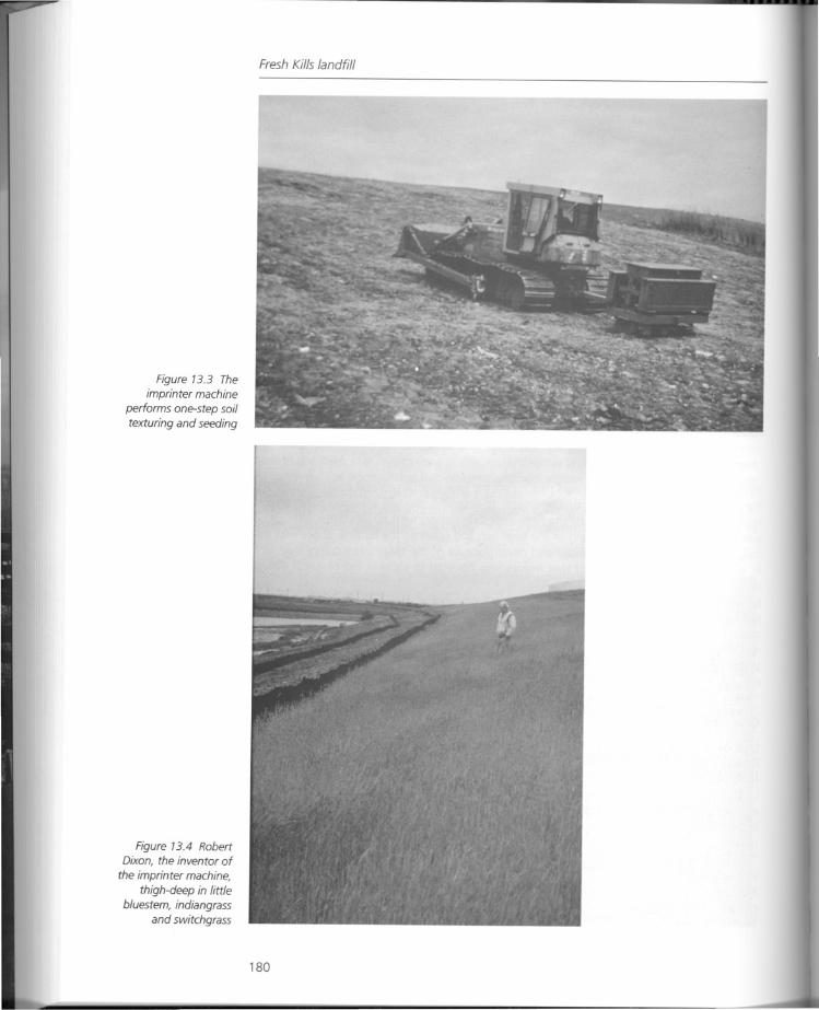
Figure 13.3 The
imprinter machineperforms one-step soiltexturing and seeding
Figure 13.4 RobertDixon, the inventor of
the imprinter machine,
thigh-deep in littlebluestem, indiangrass
and switchgrass
Fresh Kills landfill
180
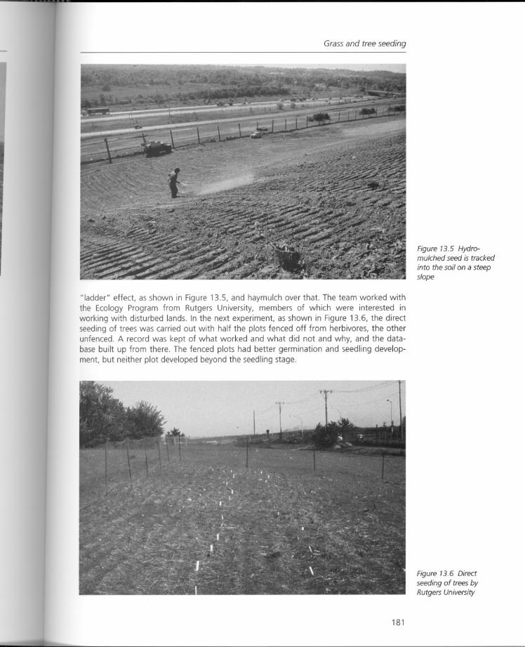
Grass and tree seeding
"ladder" effect, as shown in Figure 13.5, and haymulch over that. The team worked withthe Ecology Program from Rutgers University, members of which were interested inworking with disturbed lands. In the next experiment, as shown in Figure 13.6, the directseeding of trees was carried out with half the plots fenced off from herbivores, the otherunfenced. A record was kept of what worked and what did not and why, and the database built up from there. The fenced plots had better germination and seedling development, but neither plot developed beyond the seedling stage.
181
Figure 13.5 Hydromulched seed is tracked
into the soil on a steepslope
Figure 13.6 Direct
seeding of trees byRutgers University
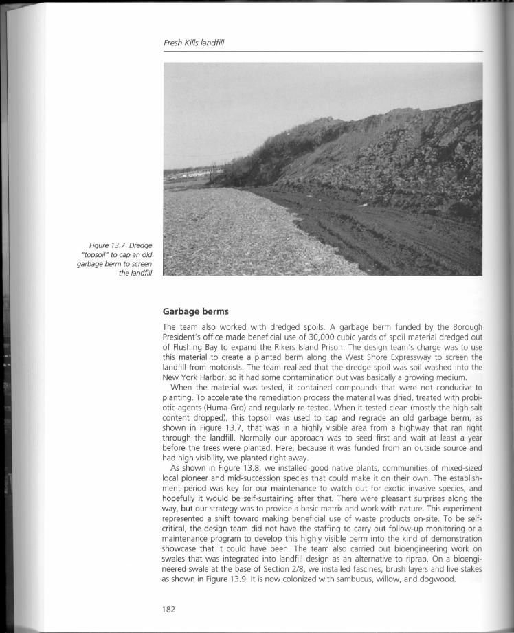
Figure 13.7 Dredge"topsoil" to cap an old
garbage berm to screenthe landfill
Fresh Kills landfill
Garbage berms
The team also worked with dredged spoils. A garbage berm funded by the BoroughPresident's office made beneficial use of 30,000 cubic yards of spoil material dredged outof Flushing Bay to expand the Rikers Island Prison. The design team's charge was to usethis material to create a planted berm along the West Shore Expressway to screen thelandfill from motorists. The team realized that the dredge spoil was soil washed into theNew York Harbor, so it had some contamination but was basically a growing medium.
When the material was tested, it contained compounds that were not conducive toplanting. To accelerate the remediation process the material was dried, treated with probiotic agents (Huma-Gro) and regularly re-tested. When it tested clean (mostly the high saltcontent dropped), this topsoil was used to cap and regrade an old garbage berm, asshown in Figure 13.7, that was in a highly visible area from a highway that ran rightthrough the landfill. Normally our approach was to seed first and wait at least a yearbefore the trees were planted. Here, because it was funded from an outside source andhad high visibility, we planted right away.
As shown in Figure 13.8, we installed good native plants, communities of mixed-sizedlocal pioneer and mid-succession species that could make it on their own. The establishment period was key for our maintenance to watch out for exotic invasive species, andhopefully it would be self-sustaining after that. There were pleasant surprises along theway, but our strategy was to provide a basic matrix and work with nature. This experimentrepresented a shift toward making beneficial use of waste products on-site. To be selfcritical, the design team did not have the staffing to carry out follow-up monitoring or amaintenance program to develop this highly visible berm into the kind of demonstrationshowcase that it could have been. The team also carried out bioengineering work onswales that was integrated into landfill design as an alternative to riprap. On a bioengineered swale at the base of Section 2/8, we installed fascines, brush layers and live stakesas shown in Figure 13.9. It is now colonized with sambucus, willow, and dogwood.
182
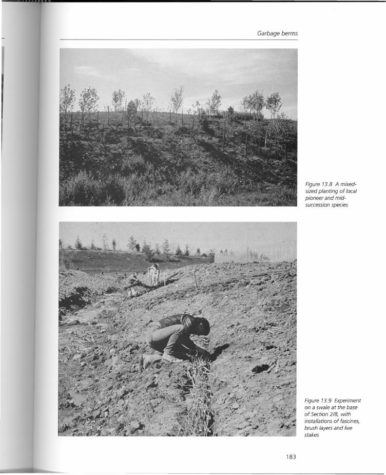
Garbage berms
183
Figure 13.8 A mixedsized planting of localpioneer and midsuccession species
Figure 13.9 Experimenton a swale at the base
of Section 2/8, withinstallations of fascines,
brush layers and livestakes
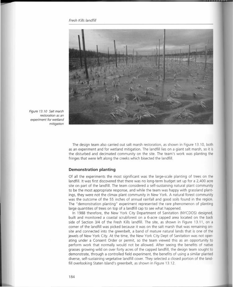
Figure 13.10 Salt marshrestoration as an
experiment for wetlandmitigation
Fresh Kills landfill
The design team also carried out salt marsh restoration, as shown in Figure 13.10, bothas an experiment and for wetland mitigation. The landfill lies on a giant salt marsh, so it isthe disturbed and decimated community on the site. The team's work was planting thefringes that were left along the creeks which bisected the landfill.
Demonstration planting
Of all the experiments the most significant was the large-scale planting of trees on thelandfill. It was first discovered that there was no long-term budget set up for a 2,400 acresite on part of the landfill. The team considered a self-sustaining natural plant communityto be the most appropriate response, and while the team was happy with grassland plantings, they were not the climax plant community in New York. A natural forest communitywas the outcome of the 55 inches of annual rainfall and good soils found in the region.The" demonstration planting" experiment represented the rare phenomenon of plantinglarge quantities of trees on top of a landfill cap to see what happened.
In 1988 therefore, the New York City Department of Sanitation (NYCDOS) designed,built and monitored a coastal scrubforest on a 6-acre capped area located on the backside of Section 3/4 of the Fresh Kills landfill. The site, as shown in Figure 13.11, on acorner of the landfill was picked because it was on the salt marsh that was remaining onsite and connected into the greenbelt, a band of mature natural lands that is one of thejewels of New York City. At the time, the New York City Dept of Sanitation was not operating under a Consent Order or permit, so the team viewed this as an opportunity toperform work that normally would not be allowed. After seeing the benefits of nativegrasses growing wild on over forty acres of the capped landfill, the design team sought todemonstrate, through a controlled field experiment, the benefits of using a similar planteddiverse, self-sustaining vegetative landfill cover. They selected a closed portion of the landfill overlooking Staten Island's greenbelt, as shown in Figure 13.12.
184
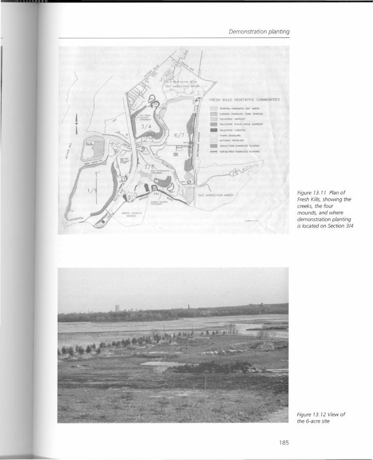
t
Demonstration planting
FRESH KILLS VEGETAl VE CO ••••••UNIIIES
SJJtAl't:D St<I":u~r. SC'W( ~"d'NA
r~:lSTJtoM( tll[~t •••
'Sell\l-' .•..• ("'{ll(,('"
_ "Ai.\lSTl!'~ '~Ul(O'IO\JHG W')OOlUlO
"",~W(IIOOV.HO
_ (JlA-S-S/'O"-OC""'IlA't '\A'''"'
- SHlIUl/l.((-~""I(O PUfoOHO
Figure 13.11 Plan ofFresh Kills, showing thecreeks, the fourmounds, and where
demonstration plantingis located on Section 3/4
185
Figure 13. 12 View ofthe 6-acre site
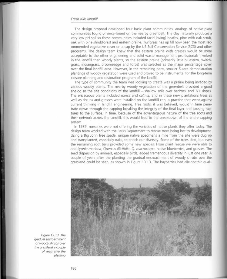
Figure 13. 13 The
gradual encroachmentof woody shrubs over
the grassland a coupleof years after the
planting
Fresh Kills landfill
The design proposal developed four basic plant communities, analogs of native plantcommunities found or once-found on the nearby greenbelt. The clay naturally produces avery low pH soil so these communities included (acid loving) heaths, pine with oak scrub,oak with pine shrubforest and eastern prairie. Turfgrass has up till now been the most recommended vegetative cover on a cap by the US Soil Conservation Service (SCS) and otherprograms. The design team knew that the eastern prairie with grasses would be moreacceptable to the other engineering and solid waste management professionals involvedin the landfill than woody plants, so the eastern prairie (primarily little bluestem, switchgrass, indiangrass, broomsedge and forbs) was selected as the major percentage coverover the final landfill area. However, in the remaining parts, smaller 6-acre demonstrationplantings of woody vegetation were used and proved to be instrumental for the long-termclosure planning and restoration program of the landfill.
The type of community the team was looking to create was a prairie being invaded byvarious woody plants. The nearby woody vegetation of the greenbelt provided a goodanalog to the site conditions of the landfill - shallow soils over bedrock and 3/1 slopes.The ericaceous plants included mirica and ca1mia, and in these new plantations trees aswell as shrubs and grasses were installed on the landfill cap, a practice that went againstcurrent thinking in landfill engineering. Tree roots, it was believed, would in time penetrate down through the capping breaking the integrity of the final layer and causing ruptures to the surface. In time, because of the advantageous nature of the tree roots andtheir network across the landfill, this would lead to the breakdown of the entire cappingsystem.
In 1989, nurseries were not offering the varieties of native plants they offer today. Thedesign team worked with the Parks Department to rescue trees being lost to development.Using a Big John tree spade, unique native specimens a mile from the site were dug upand transplanted, especially oaks, to enrich our diversity. Some of the trees died, but eventhe remaining root balls provided some new species. From plant rescue we were able toadd Lyonia mariana, Quercus illicifolia, Q. macrocarpa, native blueberries, and grasses. Theseed dispersion by animals, especially birds, added tremendous diversity in just one year. Acouple of years after the planting the gradual encroachment of woody shrubs over thegrassland could be seen, as shown in Figure 13.13. The bayberries had allelopathic quali-
186
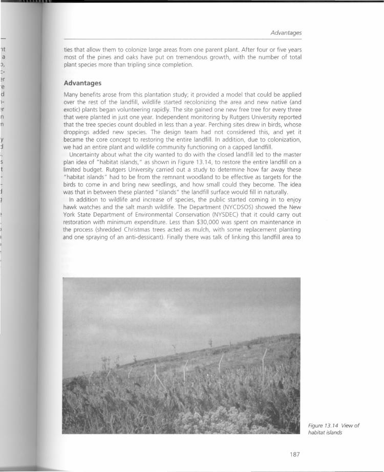
Advantages
ties that allow them to colonize large areas from one parent plant. After four or five yearsmost of the pines and oaks have put on tremendous growth, with the number of totalplant species more than tripling since completion.
Advantages
Many benefits arose from this plantation study; it provided a model that could be appliedover the rest of the landfill, wildlife started recolonizing the area and new native (andexotic) plants began volunteering rapidly. The site gained one new free tree for every threethat were planted in just one year. Independent monitoring by Rutgers University reportedthat the tree species count doubled in less than a year. Perching sites drew in birds, whosedroppings added new species. The design team had not considered this, and yet itbecame the core concept to restoring the entire landfill. In addition, due to colonization,we had an entire plant and wildlife community functioning on a capped landfill.
Uncertainty about what the city wanted to do with the closed landfill led to the masterplan idea of "habitat islands," as shown in Figure 13.14, to restore the entire landfill on alimited budget. Rutgers University carried out a study to determine how far away these"habitat islands" had to be from the remnant woodland to be effective as targets for thebirds to come in and bring new seedlings, and how small could they become. The ideawas that in between these planted "islands" the landfill surface would fill in naturally.
In addition to wildlife and increase of species, the public started coming in to enjoyhawk watches and the salt marsh wildlife. The Department (NYCDSOS) showed the NewYork State Department of Environmental Conservation (NYSDEC) that it could carry outrestoration with minimum expenditure. Less than $30,000 was spent on maintenance inthe process (shredded Christmas trees acted as mulch, with some replacement plantingand one spraying of an anti-dessicant). Finally there was talk of linking this landfill area to
187
Figure 13. 14 View ofhabitat islands
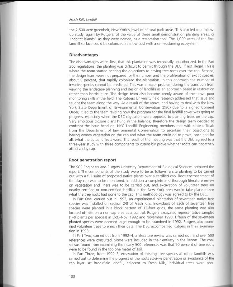
Fresh Kills landfill
the 2,500-acre greenbelt, New York's jewel of natural park areas. This also led to a followup study, again by Rutgers, of the value of these small demonstration planting areas, or"habitat islands" as they were named, as a restoration tool. The 1,000 acres of the finallandfill surface could be colonized at a low cost with a self-sustaining ecosystem.
Disadvantages
The disadvantages were, first, that this plantation was technically unauthorized. In the Part360 regulations, the planting was difficult to permit through the DEC, if not illegal. This iswhere the team started hearing the objections to having tree roots over the cap. Second,the design team were not prepared for the number and the proliferation of exotic species,about 5 percent, that rapidly colonized the plantation. In this approach the number ofinvasive species cannot be predicted. This was a major problem during the transition fromviewing the landscape planning and design of landfills as an approach based in restorationrather than horticulture. The design team also became keenly aware of their own poormonitoring skills in the field. The Rutgers University field research addressed that issue andtaught the team along the way. As a result of the above, and having to deal with the NewYork State Department of Environmental Conservation (DEC) due to a signed ConsentOrder, it led to the team revising how the program for the final landfill cover was going toprogress, especially when the DEC regulators were opposed to planting trees on the cap.Very ambitious closure plans hung in the balance, therefore the design team decided toconfront the issue head on. NYC Landfill Engineering members met with state officialsfrom the Department of Environmental Conservation to ascertain their objections tohaving woody vegetation on the cap and what the team could do to prove, once and forall, what the actual effects were. The result of the meeting was that the DEC agreed to athree-year study with three components to ostensibly prove whether roots can negativelyaffect a clay cap.
Root penetration report
The SCS Engineers and Rutgers University Department of Biological Sciences prepared thereport. The components of the study were to be as follows: a site planting to be carriedout with a full suite of proposed native plants over a certified cap. Root encroachment ofthe clay cap was to be monitored. In addition a complete and thorough literature reviewon vegetation and liners was to be carried out, and excavation of volunteer trees onnearby certified or non-certified landfills in the New York area would take place to seewhat the tree roots had done to the cap. This methodology was agreed to by the DEe.
In Part One, carried out in 1992, an experimental plantation of seventeen native treespecies was installed on section 2/8 of Fresh Kills. Individuals of each of seventeen treespecies were planted in a block pattern of 12-foot grids, the same planting was alsolocated off-site on a non-cap area as a control. Rutgers excavated representative samples(1-9 plants per species) in Oct.-Nov. 1992 and November 1993. Fifteen of the seventeenplanted species were deemed large enough to be examined in 1992. Rutgers also examined volunteer trees to enrich their data. The DEC accompanied Rutgers in their examination in 1993.
In Part Two, carried out from 1992-4, a literature review was carried out, and over 500references were consulted. Some were included in their entirety in the Report. The consensus found from examining the nearly 500 references was that 90 percent of tree rootswere to be found in the top one meter of soil.
In Part Three, from 1992-3, excavation of existing tree species at other landfills wascarried out to determine the progress of the roots vis-a-vis penetration or avoidance of thecap layer. At Brookfield landfill, adjacent to Fresh Kills, individual trees were pho-
188
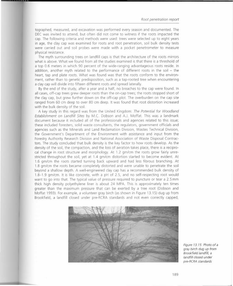
Root penetration report
tographed, measured, and excavation was performed every season and documented. TheDEC was invited to attend, but often did not come to witness if the roots impacted thecap. The following criteria and methods were used: trees were selected up to eight yearsin age, the clay cap was examined for roots and root penetration, soil bulk density testswere carried out and soil probes were made with a pocket penetrometer to measurephysical resistance.
The myth surrounding trees on landfill caps is that the architecture of the roots mirrorswhat is above. What we found from all the studies examined is that there is a threshold of
a top 0.6 meters in which 90 percent of the wide-ranging advantageous roots reside. Inaddition, another myth related to the performance of different roots in the soil - theheart, tap and plate roots. What was found was that the roots conform to the environment, rather than to genetic predisposition, such as a tap-rooted tree when encounteringa clay cap will divide into fifteen different roots and spread laterally.
By the end of the study, after a year and a half, no breaches to the cap were found. Inall cases, off-cap trees grew deeper roots than the on-cap trees; the roots stopped short ofthe clay cap, but grew further down on the off-cap plot. The overburden on the cap siteranged from 60 cm deep to over 80 cm deep. It was found that root distortion increasedwith the bulk density of the soil.
A key study in this regard was from the United Kingdom: The Potential for WoodlandEstablishment on Landfill Sites by M.C. Dobson and A.J. Moffat. This was a landmarkdocument because it included all of the professionals and agencies related to this issue;these included foresters, solid waste consultants, the regulators, government officials andagencies such as the Minerals and Land Reclamation Division, Wastes Technical Division,the Government's Department of the Environment with assistance and input from theForestry Authority Research Division and National Association of Waste Disposal Contractors. The study concluded that bulk density is the key factor to how roots develop. As thedensity of the soil, the compaction, and the loss of aeration takes place, there is a reciprocal change in root structure and morphology. At 1.2 gm/cm the roots grow fairly unrestricted throughout the soil, yet at 1.4 gm/cm distortion started to become evident. At1.6 gm/cm the roots started turning back upward and had less fibrous branching. At1.8 gm/cm the roots became completely distorted and were unable to penetrate the soilbeyond a shallow depth. A well-engineered clay cap has a recommended bulk density of1.8-1.9 gm/cm. It is like concrete, with a pH of 2.5, and no self-respecting root wouldwant to go into that. The typical value of pressure required to puncture or tear a 2.5 mmthick high density polyethylene liner is about 24 MPA. This is approximately ten timesgreater than the maximum pressure that can be exerted by a tree root (Dobson andMoffat 1993). For example, a volunteer gray birch (as shown in Figure 13.15) dug up fromBrookfield, a landfill closed under pre-RCRA standards and not even correctly capped,
189
Figure 13. 15 Photo of agray birch dug up fromBrookfield landfill, alandfill closed under
pre-RCRA standards
Fresh Kills landfill
grew roots that exhibited startling deviation from genetic traits by confining all its roots tothe thin mantle of overburden over the non-certified cap, even though the clay was poorlycompacted and the soil cover was no more than six inches deep. In short, it grew like apancake. Similar results were found in excavations on local landfills throughout the NewYork metropolitan area.
Again, the study by M.C. Dobson and A.J. Moffat that was referenced in the literaturereview of the Root Penetration Report concluded that the restrictions on tree planting oncapped landfills was unwarranted. The study stated: "since 1986, flexibility in landscapingrestored sites has been considerably reduced as a result of guidance contained in theDepartment of the Environment's Waste Management Paper No. 26, Landfilling Wastes.This recommends that trees should not be planted on containment landfill sites." As aresult of the Dobson and Moffat study that concluded that there is no empirical evidencethat roots breach caps, and that tree roots do not exert enough pressure to penetrate anengineered cap, the directive contained in the DOE's Management Paper No. 26 excludingtrees from containment landfills was rescinded. Trees are now more commonly planted oncaps in the United Kingdom, and a large number of parks and Festival Gardens withimmense tree planting programs are located on former landfill sites. To date, the DEC hasnot rendered a formal decision on the Root Penetration Report, and the restorationprogram has not been adopted by the New York City Department of Sanitation.
Landfill forests?
In the landfill restoration field, the landscape architect usually comes cap in hand at theend of the process. The design team first became involved as landfill engineers and thenmoved into their role as landscape architects. One thing is certain, there is a paucity of realrestoration on capped landfills in this country. This includes the application of tree massingover broad areas of the final cover. At so-called restored landfills small clusters of trees, if
used at all, are still confined to deeper-soil areas. If the EPA has no problem with trees onthe cap, why are there not more forests on landfills?
Bibliography
Dobson, M.C. and A.J. Moffat (1993) The Potential for Woodland Establishment on Landfill Sites,London: Department of Environment.
Robinson, George R. and Steven N. Handel (1992) Narrative Report on the Habitat Island Concept,Biology Department, Rutgers University, October.
Robinson, George R. and Steven N. Handel (1993) "Forest Restoration on a Closed Landfill: RapidAddition of New Species by Bird Dispersal," Conservation Biology 7(2) June.
190
Response
RESPONSE
Horticultural research at the interface of
remediation, waste management and site design
Perhaps more than any other case study in this compilation, this project best illustrates therelationship between research and innovative practices. While many models have beenpresented that describe a strong relationship between research and practice, the FreshKills project may come closest to the laboratory approach, in which pioneering remediation methods and systems are carefully monitored so that data can be generated tosupport future uses of these strategies for landfill capping, stormwater management andhabitat development. What's particularly interesting in this project is how the innovativethinking and applications grew out of both resource constraints and technological limitations. The garbage berms resulted from the chance availability of local dredge materials asa beneficial waste product. Another resourceful strategy was the use of salvaged localnative plants that created the opportunity to "work with nature" as the landfill was reforested. Clearly as engineers and designers explore unchartered territory, their reliance onthe skills and resources of researchers, particularly from local academic institutions,becomes all the more significant when building up a database and assessing benefits,both predicted and unanticipated. In the case of Fresh Kills, two unanticipated benefitswere the increased bird populations and the relative low costs of the restoration techniques.
In addition to the ongoing studies done during this project by researchers at RutgersUniversity, prior research was notably used to inform and validate innovative strategies.William Young and his associates established precedence to various studies from England,that resulted in the rescinding of the existing policies and enabling large-scale revegetationto be implemented over the engineered cap. Young notes, as many conference participants have done, how important the interdisciplinary nature of the research and reviewprocess was to the Department of Environment that had jurisdiction over the site, becauseit included a diverse range of professionals and government officials.
This landmark project represents a benchmark of remediation project as laboratory.Many of the techniques, including the use of seeding machines, the "Iaddering" of thesoil to increase infiltration, the planting of trees on the engineered cap, the use of planted"habitat islands" to begin the process of reforestation were methods rarely used in thiscountry for landfill reclamation. As a precedent, Fresh Kills landfill represents an achievement of synthesis between engineered and ecological systems. Several other projects inthis book present the great potential of plant material for remediation, but in this case theintent was to recreate a native forest not for soil remediation but instead for control of
stormwater run-off. The benefits at this scale are enormous because the site in its fullyreforested state represents a considerable expansion of the existing open space/greenbeltsystem. The many benefits of an enlarged native habitat ironically result from the conversion of a refuge dump into a wildlife sanctuary. As William Young states, the team wentthrough a process of transformation evolving from engineering to landscape architectureas the reforestation was implemented. This notion of transformation, and reliance oninterdisciplinary teams, echoes what others have implied, including Eric Carman who suggested that the next evolution in phytoremediation would be to add landscape design professionals to the project teams. Clearly in created wetlands, phytoremediation, brownfieldredevelopment and now in landfill reclamation, the application of environmental engineering in combination with landscape design offers greater benefits than each disciplinealone would produce, including reduction or elimination of contaminants, containment of
191

Fresh Kills landfill
contaminants, redevelopment, created habitats, increased open space, recreationalopportunities and regenerative systems often providing treatment at a lower cost thanartificially engineered solutions. If we are to reap the full benefits of engineering, scienceand design, it is, as this paper so well illustrates, imperative that those involved in theseprojects collect the critical assessment data so that others may use this information to gainthe endorsement of the governing and permitting agencies.
192
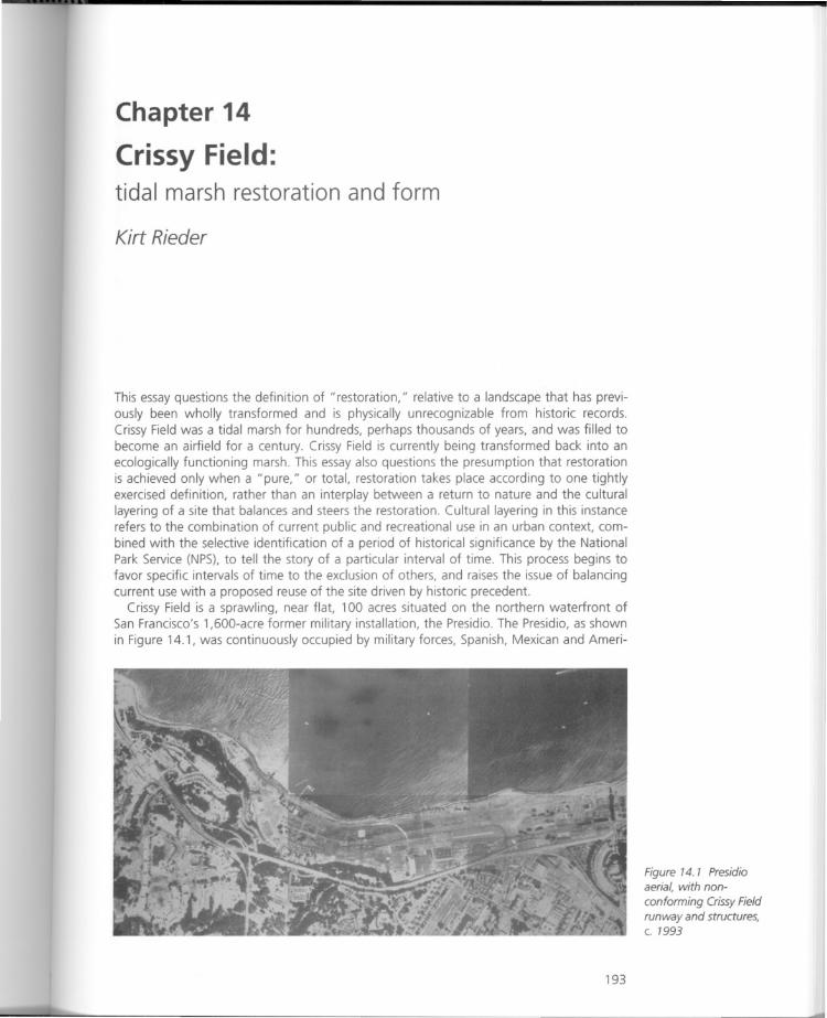
Chapter 14
Crissy Field:tidal marsh restoration and form
Kirt Rieder
This essay questions the definition of "restoration," relative to a landscape that has previously been wholly transformed and is physically unrecognizable from historic records.Crissy Field was a tidal marsh for hundreds, perhaps thousands of years, and was filled tobecome an airfield for a century. Crissy Field is currently being transformed back into anecologically functioning marsh. This essay also questions the presumption that restorationis achieved only when a "pure," or total, restoration takes place according to one tightlyexercised definition, rather than an interplay between a return to nature and the culturallayering of a site that balances and steers the restoration. Cultural layering in this instancerefers to the combination of current public and recreational use in an urban context, combined with the selective identification of a period of historical significance by the NationalPark Service (NPS), to tell the story of a particular interval of time. This process begins tofavor specific intervals of time to the exclusion of others, and raises the issue of balancingcurrent use with a proposed reuse of the site driven by historic precedent.
Crissy Field is a sprawling, near flat, 100 acres situated on the northern waterfront ofSan Francisco's 1,600-acre former military installation, the Presidio. The Presidio, as shownin Figure 14.1, was continuously occupied by military forces, Spanish, Mexican and Ameri-
193
Figure 14.1 Presidioaerial, with non
conforming Crissy Fieldrunway and structures,c. 1993
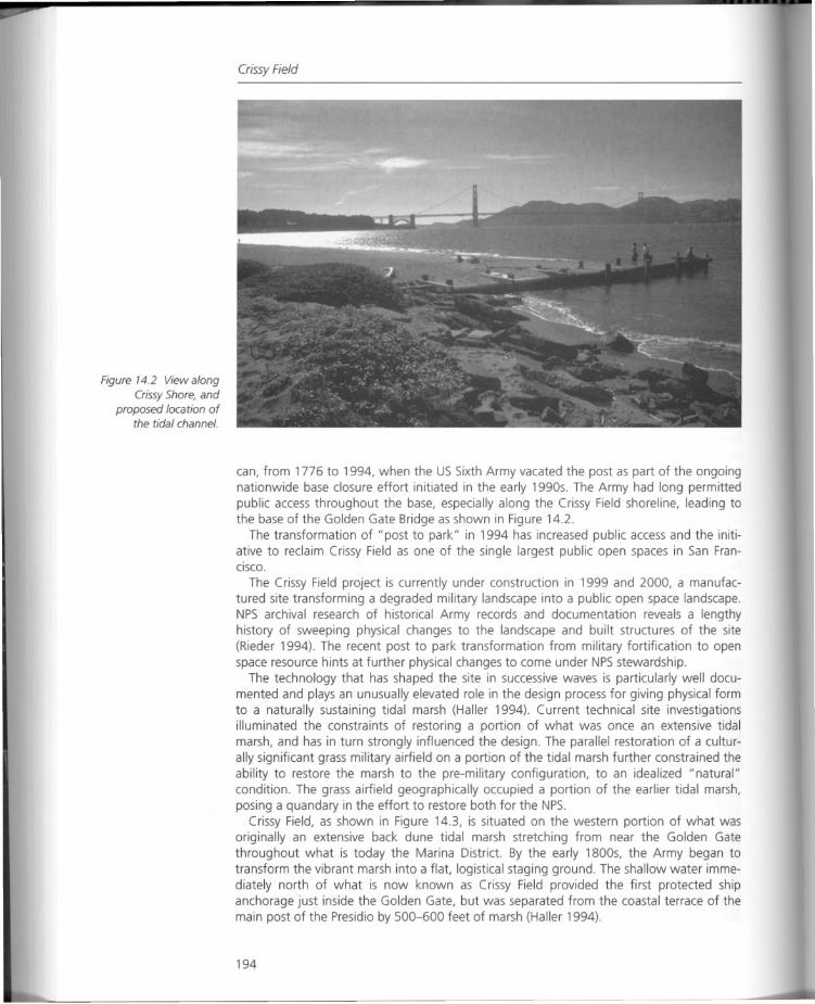
Figure 14.2 View alongCrissy Shore, and
proposed location ofthe tidal channel.
Crissy Field
can, from 1776 to 1994, when the US Sixth Army vacated the post as part of the ongoingnationwide base closure effort initiated in the early 1990s. The Army had long permittedpublic access throughout the base, especially along the Crissy Field shoreline, leading tothe base of the Golden Gate Bridge as shown in Figure 14.2.
The transformation of "post to park" in 1994 has increased public access and the initiative to reclaim Crissy Field as one of the single largest public open spaces in San FranCISCO.
The Crissy Field project is currently under construction in 1999 and 2000, a manufactured site transforming a degraded military landscape into a public open space landscape.NPS archival research of historical Army records and documentation reveals a lengthyhistory of sweeping physical changes to the landscape and built structures of the site(Rieder 1994). The recent post to park transformation from military fortification to openspace resource hints at further physical changes to come under NPSstewardship.
The technology that has shaped the site in successive waves is particularly well documented and plays an unusually elevated role in the design process for giving physical formto a naturally sustaining tidal marsh (Haller 1994). Current technical site investigationsilluminated the constraints of restoring a portion of what was once an extensive tidalmarsh, and has in turn strongly influenced the design. The parallel restoration of a culturally significant grass military airfield on a portion of the tidal marsh further constrained theability to restore the marsh to the pre-military configuration, to an idealized "natural"condition. The grass airfield geographically occupied a portion of the earlier tidal marsh,posing a quandary in the effort to restore both for the NPS.
Crissy Field, as shown in Figure 14.3, is situated on the western portion of what wasoriginally an extensive back dune tidal marsh stretching from near the Golden Gatethroughout what is today the Marina District. By the early 1800s, the Army began totransform the vibrant marsh into a flat, logistical staging ground. The shallow water immediately north of what is now known as Crissy Field provided the first protected shipanchorage just inside the Golden Gate, but was separated from the coastal terrace of themain post of the Presidio by 500-600 feet of marsh (Haller 1994).
194
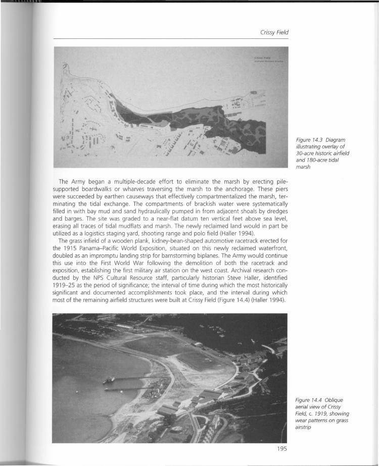
Crissy Field
The Army began a multiple-decade effort to eliminate the marsh by erecting pilesupported boardwalks or wharves traversing the marsh to the anchorage. These pierswere succeeded by earthen causeways that effectively compartmentalized the marsh, terminating the tidal exchange. The compartments of brackish water were systematicallyfilled in with bay mud and sand hydraulically pumped in from adjacent shoals by dredgesand barges. The site was graded to a near-flat datum ten vertical feet above sea level,erasing all traces of tidal mudflats and marsh. The newly reclaimed land would in part beutilized as a logistics staging yard, shooting range and polo field (Haller 1994).
The grass infield of a wooden plank, kidney-bean-shaped automotive racetrack erected forthe 1915 Panama-Pacific World Exposition, situated on this newly reclaimed waterfront,doubled as an impromptu landing strip for barnstorming biplanes. The Army would continuethis use into the First World War following the demolition of both the racetrack andexposition, establishing the first military air station on the west coast. Archival research conducted by the NPS Cultural Resource staff, particularly historian Steve Haller, identified1919-25 as the period of significance; the interval of time during which the most historicallysignificant and documented accomplishments took place, and the interval during whichmost of the remaining airfield structures were built at Crissy Field (Figure 14.4) (Haller 1994).
195
Figure 14.3 Diagramillustrating overlay of3D-acre historic airfieldand 180-acre tidalmarsh
Figure 14.4 Obliqueaerial view of CrissyField, c. 1919, showingwear patterns on grassairstrip
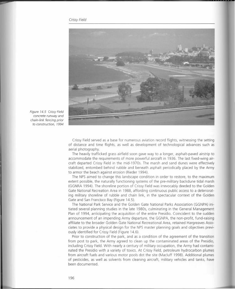
Figure 14.5 Crissy Fieldconcrete runway and
chain-link fencing priorto construction, 1994
Crissy Field
Crissy Field served as a base for numerous aviation record flights, witnessing the settingof distance and time flights, as well as development of technological advances such asaerial photography.
The heavily trafficked grass airfield soon gave way to a longer, asphalt-paved airstrip toaccommodate the requirements of more powerful aircraft in 1936. The last fixed-wing aircraft departed Crissy Field in the mid-1970s. The marsh and sand dunes were effectivelystabilized, entombed behind rubble and beneath asphalt periodically placed by the Armyto armor the beach against erosion (Rieder 1994).
The NPSaimed to change this landscape condition in order to restore, to the maximumextent possible, the naturally functioning systems of the pre-military backdune tidal marsh(GGNRA 1994). The shoreline portion of Crissy Field was irrevocably deeded to the GoldenGate National Recreation Area in 1988, affording continuous public access to a deteriorating military shoreline of rubble and chain link, in the spectacular context of the GoldenGate and San Francisco Bay (Figure 14.5).
The National Park Service and the Golden Gate National Parks Association (GGNPA) ini
tiated several planning studies in the late 1980s, culminating in the General ManagementPlan of 1994, anticipating the acquisition of the entire Presidio. Coincident to the suddenannouncement of an impending Army departure, the GGNPA, the non-profit. fund-raisingaffiliate to the broader Golden Gate National Recreational Area, retained Hargreaves Associates to provide a physical design for the NPS master planning goals and objectives previously identified for Crissy Field (Figure 14.6).
Prior to construction of the park, and as a condition of the agreement of the transitionfrom post to park, the Army agreed to clean up the contaminated areas of the Presidio,including Crissy Field. With nearly a century of military occupation, the Army had contaminated the Presidio with a variety of toxics. At Crissy Field, petroleum hydrocarbon plumesfrom aircraft fuels and various motor pools dot the site (Macluff 1998). Additional plumesof pesticides, as well as solvents from cleaning aircraft, military vehicles and tanks, havebeen documented.
196
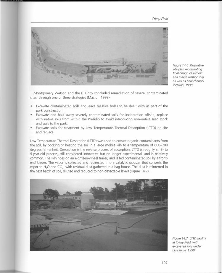
Crissy Field
Montgomery Watson and the IT Corp concluded remediation of several contaminatedsites, through one of three strategies (Macluff 1998):
• Excavate contaminated soils and leave massive holes to be dealt with as part of thepark construction.
• Excavate and haul away severely contaminated soils for incineration offsite, replacewith native soils from within the Presidio to avoid introducing non-native seed stockand soils to the park.
• Excavate soils for treatment by Low Temperature Thermal Desorption (LnD) on-siteand replace.
Low Temperature Thermal Desorption (LnD) was used to extract organic contaminants fromthe soil, by cooking or heating the soil in a large mobile kiln to a temperature of 600-700degrees fahrenheit. Desorption is the reverse process of absorption. LnD is roughly an 8- to9-year-old process, still considered innovative but no longer experimental, and is relativelycommon. The kiln rides on an eighteen-wheel trailer, and is fed contaminated soil by a frontend loader. The vapor is collected and redirected into a catalytic oxidizer that converts thevapor to H20 and COb with residual dust gathered in a bag house. The dust is reinterred inthe next batch of soil, diluted and reduced to non-detectable levels (Figure 14.7).
197
Figure 14.6 Illustrativesite plan representingfinal design of airfieldand marsh relationship,as well as final channel
location, 1998
Figure 14.7 LTTO facility
at Crissy Field, withexcavated soils under
blue tarps, 1998
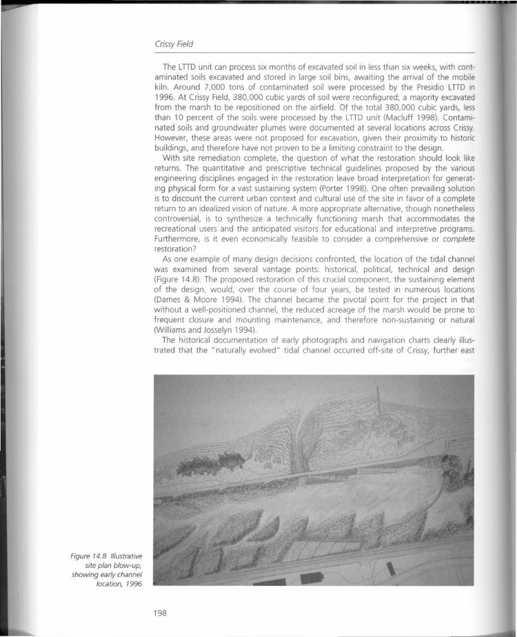
Figure 14.8 Illustrativesite plan blow-up,
showing early channellocation, 1996
Crissy Field
The LnD unit can process six months of excavated soil in less than six weeks, with contaminated soils excavated and stored in large soil bins, awaiting the arrival of the mobilekiln. Around 7,000 tons of contaminated soil were processed by the Presidio LnD in1996. At Crissy Field, 380,000 cubic yards of soil were reconfigured; a majority excavatedfrom the marsh to be repositioned on the airfield. Of the total 380,000 cubic yards, lessthan 10 percent of the soils were processed by the LnD unit (Macluff 1998). Contaminated soils and groundwater plumes were documented at several locations across Crissy.However, these areas were not proposed for excavation, given their proximity to historicbuildings, and therefore have not proven to be a limiting constraint to the design.
With site remediation complete, the question of what the restoration should look likereturns. The quantitative and prescriptive technical guidelines proposed by the variousengineering disciplines engaged in the restoration leave broad interpretation for generating physical form for a vast sustaining system (Porter 1998). One often prevailing solutionis to discount the current urban context and cultural use of the site in favor of a completereturn to an idealized vision of nature. A more appropriate alternative, though nonethelesscontroversial, is to synthesize a technically functioning marsh that accommodates therecreational users and the anticipated visitors for educational and interpretive programs.Furthermore, is it even economically feasible to consider a comprehensive or completerestoration?
As one example of many design decisions confronted, the location of the tidal channelwas examined from several vantage points: historical, political, technical and design(Figure 14.8). The proposed restoration of this crucial component, the sustaining elementof the design, would, over the course of four years, be tested in numerous locations(Dames & Moore 1994). The channel became the pivotal point for the project in thatwithout a well-positioned channel, the reduced acreage of the marsh would be prone tofrequent closure and mounting maintenance, and therefore non-sustaining or natural(Williams and Josselyn 1994).
The historical documentation of early photographs and navigation charts clearly illustrated that the "naturally evolved" tidal channel occurred off-site of Crissy, further east
198
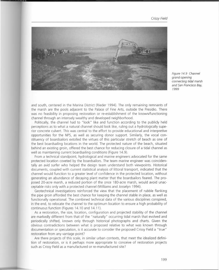
Crissy Field
and south, centered in the Marina District (Rieder 1994). The only remaining remnants ofthe marsh are the pools adjacent to the Palace of Fine Arts, outside the Presidio. Therewas no feasibility in proposing restoration or re-establishment of the known/functioningchannel through an intensely wealthy and developed neighborhood.
Politically, the channel had to "look" like and function according to the publicly heldperceptions as to what a natural channel should look like, ruling out a hydrologically superior concrete culvert. This was central to the effort to provide educational and interpretiveopportunities for the NPS, as well as securing donor support. Similarly, the vocal constituency of boardsailors extolled the virtues of this particular stretch of beach as one ofthe best boardsailing locations in the world. The protected nature of the beach, situatedbehind an existing groin, offered the best chance for reducing closure of a tidal channel aswell as maintaining current boardsailing conditions (Figure 14.9).
From a technical standpoint, hydrological and marine engineers advocated for the sameprotected location coveted by the boardsailors. The team marine engineer was coincidentally an avid surfer who helped the design team understand both viewpoints. Historicaldocuments, coupled with current statistical analysis of littoral transport, indicated that thechannel would function to a greater level of confidence in the protected location, withoutgenerating an abundance of decaying plant matter that the boardsailors feared. The proposed 20-acre marsh, a reduced portion of the once lBO-acre marsh, would avoid unacceptable risks only with a protected channel (Williams and Josselyn 1994).
Geotechnical investigations reinforced the view that the placement of rubble flankingthe pipe groin afforded the best chance for keeping the channel stable in place, as well asfunctionally operational. The combined technical data of the various disciplines conspired,in the end, to relocate the channel to the optimum location to ensure a high probability ofcontinuous function (Figures 14.10 and 14.11).
As a restoration, the size, location, configuration and projected stability of the channelare markedly different from that of the "naturally" occurring tidal marsh that evolved andperiodically shifted, known only through historical photographs and charts. Given theobvious contradictions between what is proposed relative to what was known throughdocumentation or speculation, is it accurate to consider the proposed Crissy Field a "true"restoration from any vantage point?
Are there projects of this scale, in similar urban contexts, that meet the idealized definition of restoration, or is it perhaps more appropriate to conceive of restoration projectssuch as Crissy Field as a manufactured or re-manufactured site?
199
Figure 14.9 Channelgrand openingconnecting tidal marshand San Francisco Bay,1999
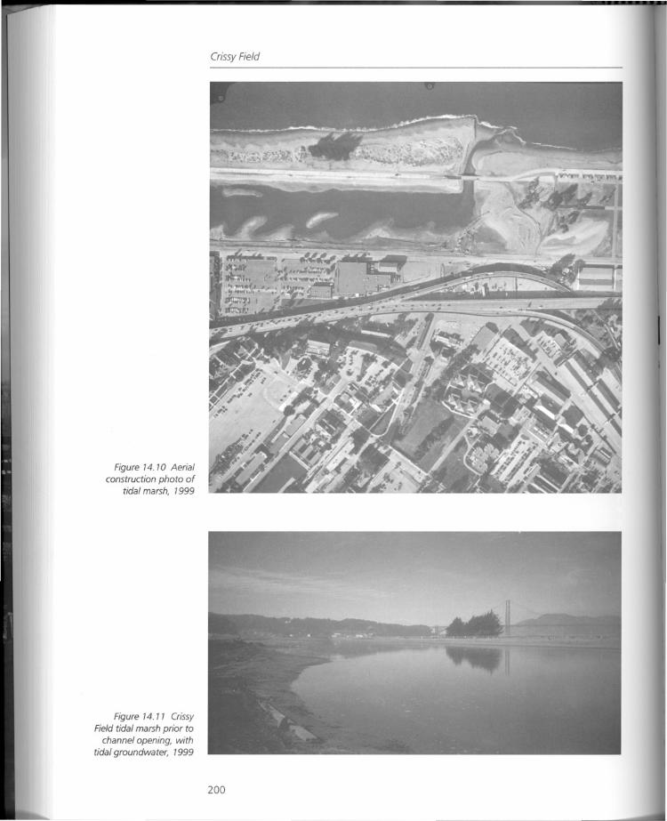
Figure 14.10 Aerialconstruction photo of
tidal marsh, 1999
Figure 14.11 CrissyField tidal marsh prior to
channel opening, withtidal groundwater, 1999
Crissy Field
200

Summary
Summary
Crissy Field is a case study in conflict and the resolution of conflict through the designprocess. Natural restoration and cultural restoration to the "era of significance" becameissues for two reasons. The definition of restoration was organizationally defined by theNational Park Service (NPS), but not necessarily embraced by the public. Similarly, the geographic positions of both the marsh and airfield during different eras, partially occupyingthe same location, defied a full restoration for both, given that they are near-polar opposites of each other. In this critique, the marsh restoration serves as an example for commenting on how the definition of a restoration was influenced.
The restoration of Crissy Field was broadly conceived of as a transformation of arecently defunct military waterfront into the centerpiece of a new national park. As thedesign developed, presentations to both the NPSstaff and during public meetings increasingly hinged on the "restoration" aspect of both the natural and cultural landscape, asillustrated in paired" before and after" figures (see Figures 14.12-14.19). The earlier NPSGeneral Management Plan specifically called for restoration at Crissy Field, and the feasibility of restoring the tidal marsh was soon after bolstered by a technical hydrologic study(GGNRA 1994). The full ramifications of executing the restoration of both cultural andnatural resource components of the landscape where less well explored.
201
Figure 14.12 *Before*photo of tidal marsh
looking northwest,1996
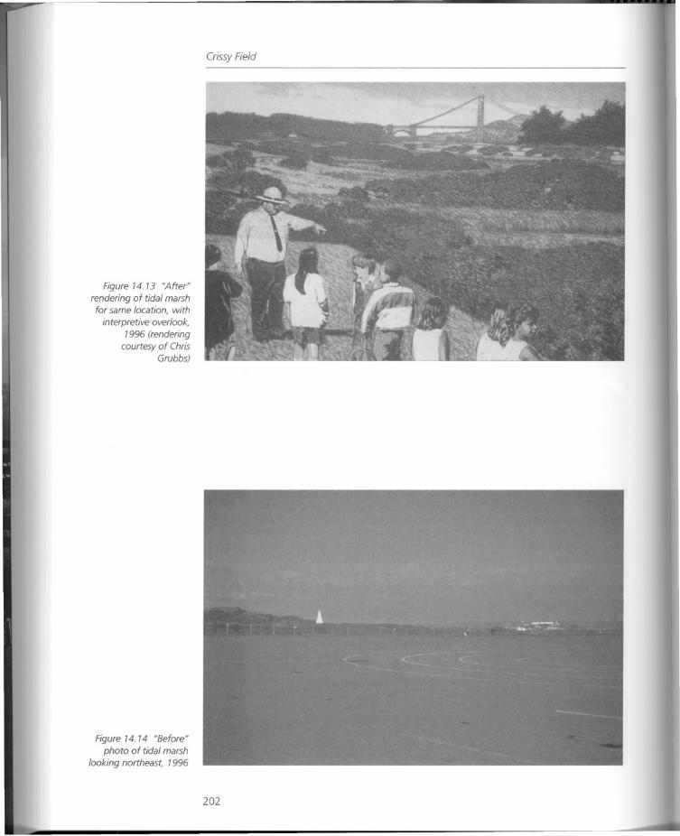
Figure 14.13 "After"rendering of tidal marshfor same location, with
interpretive overlook,1996 (rendering
courtesy of ChrisGrubbs)
Figure 14.14 "Before"photo of tidal marsh
looking northeast, 1996
Crissy Field
202
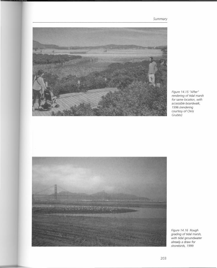
Summary
203
Figure 14.15 "After"rendering of tidal marshfor same location, withaccessible boardwalk,
1996 (renderingcourtesy of ChrisGrubbs)
Figure 14 16 Roughgrading of tidal marsh,with tidal groundwateralready a draw forshorebirds, 1999
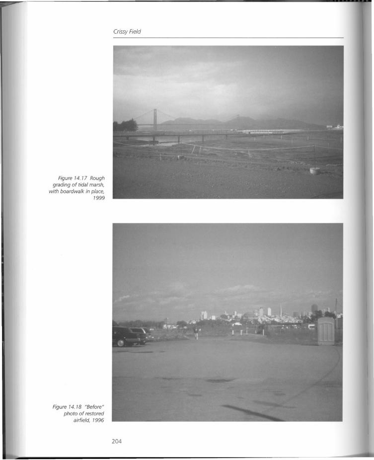
Figure 14.17 Roughgrading of tidal marsh,
with boardwalk in place,1999
Figure 14.18 HBeforeHphoto of restored
airfield, 1996
Crissy Field
204
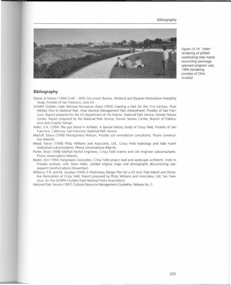
Bibliography
Bibliography
Dames & Moore (1994) Draft - 90% Document Review, Wetland and Riparian Restoration FeasibilityStudy, Presidio of San Francisco, June 24.
GGNRA (Golden Gate National Recreation Area) (1994) Creating a Park for the 21st Century, fromMilitary Post to National Park. Final General Management Plan Amendment, Presidio of San Francisco. Report prepared for the US Department of the Interior, National Park Service, Denver ServiceCenter. Report prepared by the National Park Service, Denver Service Center, Branch of Publications and Graphic Design.
Haller, SA (1994) The Last Word in Airfields. A Special History Study of Crissy Field, Presidio of SanFrancisco, California, San Francisco: National Park Service.
Macluff, Eliana (1998) Montgomery Watson, Presidio soil remediation consultants. Phone conversation (March).
Mead, Aaron (1998) Philip Williams and Associates, Ltd., Crissy Field hydrology and tidal marshrestoration subconsultants. Phone conversations (March).
Porter, Brad (1998) Moffatt Nichol Engineers, Crissy Field marine and civil engineer subconsultants.Phone conversations (March).
Rieder, Kirt (1994) Hargreaves Associates, Crissy Field project lead and landscape architects. Visits toPresidio archives, with Steve Haller, yielded original maps and photographs documenting subsequent transformations (November).
Williams, P.B. and M. Josselyn (1994) A Preliminary Design Plan for a 20 Acre Tidal Marsh and Shoreline Restoration at Crissy Field, Report prepared by Philip Williams and Associates, Ltd, San Francisco, for the GGNPA (Golden Gate National Parks Association).
National Park Service (1997) Cultural Resource Management Guideline, Release NO.5.
205
Figure 14.19 NAfterNrendering of airfieldoverlooking tidal marsh,reconciling seeminglyopposed program uses,
1996 (renderingcourtesy of ChrisGrubbs)
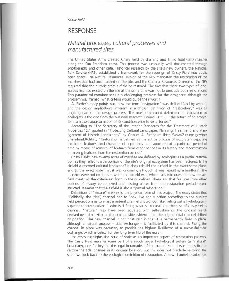
Crissy Field
RESPONSE
Natural processes, cultural processes andmanufactured sites
The United States Army created Crissy Field by draining and filling tidal (salt) marshesalong the San Francisco coast. This process was unusually well documented throughphotographs and other data. Historical research by the site's new owners, the NationalPark Service (NPS), established a framework for the redesign of Crissy Field into publicopen space. The Natural Resources Division of the NPS mandated the restoration of themarshes that had once existed on the site, and the Cultural Resources Division of the NPS
required that the historic grass airfield be restored. The fact that these two types of landscapes had not existed on the site at the same time was not to preclude both restorations.This paradoxical mandate set up a challenging problem for the designers: although theproblem was framed, what criteria would guide their work?
As Rieder's essay points out, how the term "restoration" was defined (and by whom),and the design implications inherent in a chosen definition of "restoration," was anongoing part of the design process. The most often-used definition of restoration byecologists is the one from the National Research Council (1992): "the return of an ecosystem to a close approximation of its condition prior to disturbance."
According to "The Secretary of the Interior Standards for the Treatment of HistoricProperties 12," quoted in "Protecting Cultural Landscapes: Planning, Treatment, and Management of Historic Landscapes" by Charles A. Birnbaum (http://www2.cr.nps.gov/tps/briefslbrief36.htm), "Restoration is defined as the act or process of accurately depictingthe form, features, and character of a property as it appeared at a particular period oftime by means of removal of features from other periods in its history and reconstructionof missing features from the restoration period."
Crissy Field's new twenty acres of marshes are defined by ecologists as a partial restoration as they reflect that a portion of the site's original ecosystem has been restored. Is theairfield a restored cultural landscape? It does rebuild the airfield in the exact same place,and to the exact scale that it was originally, although it was rebuilt as a landform. Themarshes were not on the site when the airfield was, which calls into question how the airfield meets all the criteria set forth in the guidelines. These ask that features from otherperiods of history be removed and missing pieces from the restoration period reconstructed. It seems that the airfield is also a "partial restoration."
Definitions of "nature" are key to the physical form of this project. The essay states that"Politically, the [tidal] channel had to 'look' like and function according to the publiclyheld perceptions as to what a natural channel should look like, ruling out a hydrologicallysuperior concrete culvert." Who is defining what is "natural"? In the case of Crissy Field'schannel, "natural" may have been equated with self-sustaining: the original marshevolved over time. Historical photos provide evidence that the original tidal channel shiftedits position. The new channel is not "natural" in that it is permanently fixed in place,although a natural process - tidal exchange - is facilitated by this channel. Fixing thechannel in place was necessary to provide the highest likelihood of a successful tidalexchange, which is critical for the long-term life of the marsh.
The essay highlights the issue of scale as an important aspect of restoration projects.The Crissy Field marshes were part of a much larger hydrological system (a "natural"boundary), one far beyond the legal boundaries of the current site. It was impossible torestore the tidal channel in its original location, but this does not preclude restoring thesite if we look back to the ecological definition of restoration. A new channel location has
206
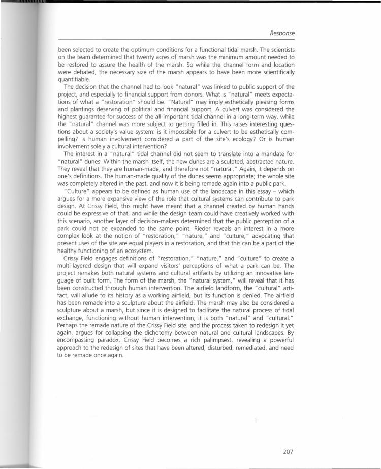
Response
been selected to create the optimum conditions for a functional tidal marsh. The scientistson the team determined that twenty acres of marsh was the minimum amount needed tobe restored to assure the health of the marsh. So while the channel form and location
were debated, the necessary size of the marsh appears to have been more scientificallyquantifiable.
The decision that the channel had to look "natural" was linked to public support of theproject, and especially to financial support from donors. What is "natural" meets expectations of what a "restoration" should be. "Natural" may imply esthetically pleasing formsand plantings deserving of political and financial support. A culvert was considered thehighest guarantee for success of the all-important tidal channel in a long-term way, whilethe "natural" channel was more subject to getting filled in. This raises interesting questions about a society's value system: is it impossible for a culvert to be esthetically compelling? Is human involvement considered a part of the site's ecology? Or is humaninvolvement solely a cultural intervention?
The interest in a "natural" tidal channel did not seem to translate into a mandate for
"natural" dunes. Within the marsh itself, the new dunes are a sculpted, abstracted nature.They reveal that they are human-made, and therefore not" natural." Again, it depends onone's definitions. The human-made quality of the dunes seems appropriate; the whole sitewas completely altered in the past, and now it is being remade again into a public park.
"Culture" appears to be defined as human use of the landscape in this essay - whichargues for a more expansive view of the role that cultural systems can contribute to parkdesign. At Crissy Field, this might have meant that a channel created by human handscould be expressive of that, and while the design team could have creatively worked withthis scenario, another layer of decision-makers determined that the public perception of apark could not be expanded to the same point. Rieder reveals an interest in a morecomplex look at the notion of "restoration," "nature," and "culture," advocating thatpresent uses of the site are equal players in a restoration, and that this can be a part of thehealthy functioning of an ecosystem.
Crissy Field engages definitions of "restoration," "nature," and "culture" to create amulti-layered design that will expand visitors' perceptions of what a park can be. Theproject remakes both natural systems and cultural artifacts by utilizing an innovative language of built form. The form of the marsh, the "natural system," will reveal that it hasbeen constructed through human intervention. The airfield landform, the "cultural" artifact, will allude to its history as a working airfield, but its function is denied. The airfieldhas been remade into a sculpture about the airfield. The marsh may also be considered asculpture about a marsh, but since it is designed to facilitate the natural process of tidalexchange, functioning without human intervention, it is both "natural" and "cultural."Perhaps the remade nature of the Crissy Field site, and the process taken to redesign it yetagain, argues for collapsing the dichotomy between natural and cultural landscapes. Byencompassing paradox, Crissy Field becomes a rich palimpsest, revealing a powerfulapproach to the redesign of sites that have been altered, disturbed, remediated, and needto be remade once again.
207
Chapter 15
The Sydney Olympics 2000:combining technology and design in theplanning of the J/ Green GamesJ/
Michael Horne
Introduction
This paper concerns the development of two urban landscape technologies that helprealize the design vision for the Sydney Olympics 2000 site at Homebush Bay. Specifically,the paper examines the development of structural soil and "eco-paving" for a major planting of Ficus hi/Ii defining the eastern edge of Olympic Plaza. The paper also describes howthese technologies connect, conceptually and functionally, with the site's overall watermanagement system, via constructed wetlands, creating a manufactured system. In doingso, the paper identifies key issues associated with the development of these technologies,emphasizing the benefits of a collaborative team response to the challenge of remadelandscapes.
Background
The Master Concept Design (MCD) was developed by Hargreaves Associates landscapearchitects and the Government Architect Design Directorate for the Olympic Co-ordinationAuthority, beginning with a two-month workshop held at Homebush Bay, in late 1996.The HAiGADD team has maintained an ongoing design coordination role, spearheadingdesign and technical issues ahead of the documentation and construction teams.
The MCD binds together an urban core of 300 hectares comprised of the major Olympicvenues, exhibition and commercial facilities rising phoenix-like from the former Metropolitan Meatworks site, as shown in Figure 15.1, abandoned in the 1960s to become a terrain
vague used indiscriminately as a dumping ground for Sydney's waste. The urban core issurrounded by the Millennium Parklands, an emerging mosaic of remnant woodlands,remade waterways and residual armaments bunkers.
Three key design "moves" are proposed within the MCD, giving form to the publicdomain. The Red Move is Olympic Plaza, the central urban space of the site, over 9hectares in size, as shown in Figure 15.2. The Green Move has five components: a centralpark called "The Overflow"; the Fig Grove defining the high point of Olympic Plaza; aseries of "green fingers" linking Millennium Parklands to the urban core; an Urban Forestof scattered eucalypts framing both the Stadium and Olympic Plaza; and a line of figsdefining the eastern edge of Olympic Plaza. The Blue Move is the use of water, at the FigGrove and at Haslams Pier, celebrating connection to the wetlands, creek and river systembeyond.
208
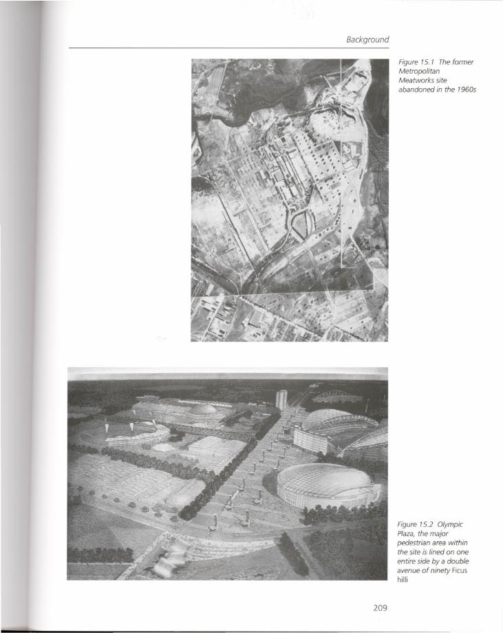
Background
209
Figure 15. 1 The formerMetropolitanMeatworks siteabandoned in the 1960s
Figure 15.2 OlympicPlaza, the major
pedestrian area withinthe site is lined on one
entire side by a doubleavenue of ninety Ficushilli
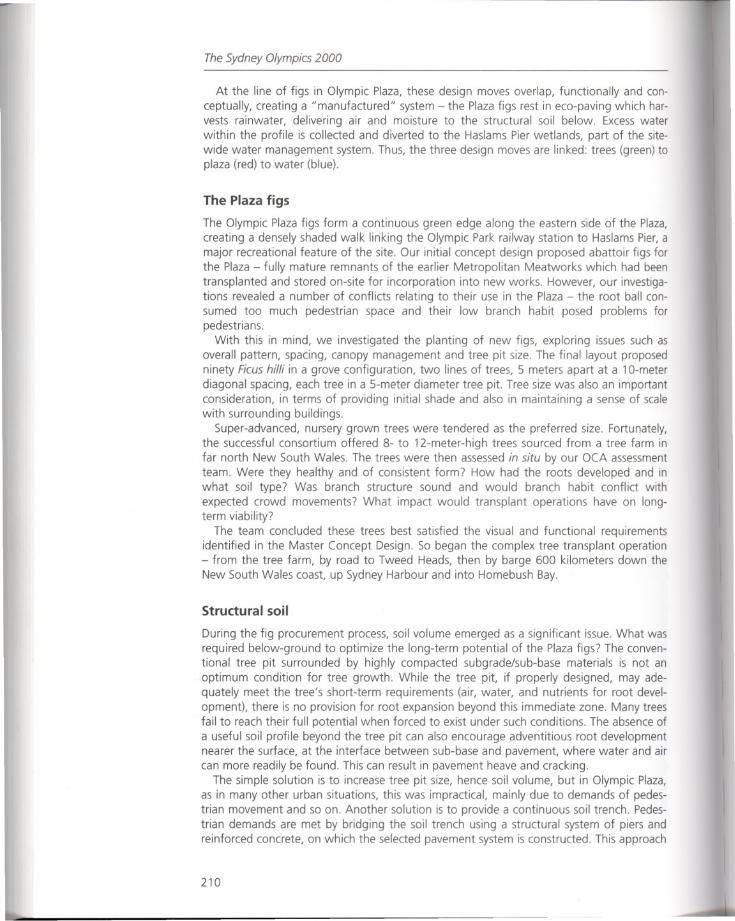
The Sydney Olympics 2000
At the line of figs in Olympic Plaza, these design moves overlap, functionally and conceptually, creating a "manufactured" system - the Plaza figs rest in eco-paving which harvests rainwater, delivering air and moisture to the structural soil below. Excess waterwithin the profile is collected and diverted to the Haslams Pier wetlands, part of the sitewide water management system. Thus, the three design moves are linked: trees (green) toplaza (red) to water (blue).
The Plaza figs
The Olympic Plaza figs form a continuous green edge along the eastern side of the Plaza,creating a densely shaded walk linking the Olympic Park railway station to Haslams Pier, amajor recreational feature of the site. Our initial concept design proposed abattoir figs forthe Plaza - fully mature remnants of the earlier Metropolitan Meatworks which had beentransplanted and stored on-site for incorporation into new works. However, our investigations revealed a number of conflicts relating to their use in the Plaza - the root ball consumed too much pedestrian space and their low branch habit posed problems forpedestrians.
With this in mind, we investigated the planting of new figs, exploring issues such asoverall pattern, spacing, canopy management and tree pit size. The final layout proposedninety Ficus hilli in a grove configuration, two lines of trees,S meters apart at a 10-meterdiagonal spacing, each tree in a 5-meter diameter tree pit. Tree size was also an importantconsideration, in terms of providing initial shade and also in maintaining a sense of scalewith surrounding buildings.
Super-advanced, nursery grown trees were tendered as the preferred size. Fortunately,the successful consortium offered 8- to 12-meter-high trees sourced from a tree farm infar north New South Wales. The trees were then assessed in situ by our OCA assessmentteam. Were they healthy and of consistent form? How had the roots developed and inwhat soil type? Was branch structure sound and would branch habit conflict withexpected crowd movements? What impact would transplant operations have on longterm viability?
The team concluded these trees best satisfied the visual and functional requirementsidentified in the Master Concept Design. So began the complex tree transplant operation- from the tree farm, by road to Tweed Heads, then by barge 600 kilometers down theNew South Wales coast, up Sydney Harbour and into Homebush Bay.
Structural soil
During the fig procurement process, soil volume emerged as a significant issue. What wasrequired below-ground to optimize the long-term potential of the Plaza figs? The conventional tree pit surrounded by highly compacted subgrade/sub-base materials is not anoptimum condition for tree growth. While the tree pit, if properly designed, may adequately meet the tree's short-term requirements (air, water, and nutrients for root development), there is no provision for root expansion beyond this immediate zone. Many treesfail to reach their full potential when forced to exist under such conditions. The absence ofa useful soil profile beyond the tree pit can also encourage adventitious root developmentnearer the surface, at the interface between sub-base and pavement, where water and aircan more readily be found. This can result in pavement heave and cracking.
The simple solution is to increase tree pit size, hence soil volume, but in Olympic Plaza,as in many other urban situations, this was impractical, mainly due to demands of pedestrian movement and so on. Another solution is to provide a continuous soil trench. Pedestrian demands are met by bridging the soil trench using a structural system of piers andreinforced concrete, on which the selected pavement system is constructed. This approach
210
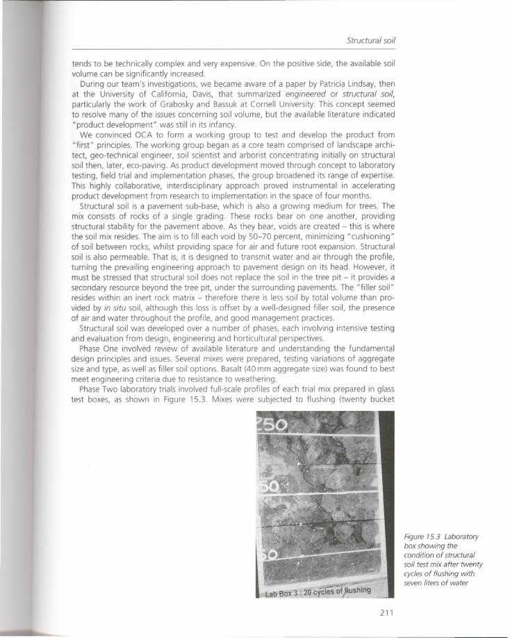
Structural soil
tends to be technically complex and very expensive. On the positive side, the available soilvolume can be significantly increased.
During our team's investigations, we became aware of a paper by Patricia Lindsay, thenat the University of California, Davis, that summarized engineered or structural soil,particularly the work of Grabosky and Bassuk at Cornell University. This concept seemedto resolve many of the issues concerning soil volume, but the available literature indicated"product development" was still in its infancy.
We convinced OCA to form a working group to test and develop the product from"first" principles. The working group began as a core team comprised of landscape architect, geo-technical engineer, soil scientist and arborist concentrating initially on structuralsoil then, later, eco-paving. As product development moved through concept to laboratorytesting, field trial and implementation phases, the group broadened its range of expertise.This highly collaborative, interdisciplinary approach proved instrumental in acceleratingproduct development from research to implementation in the space of four months.
Structural soil is a pavement sub-base, which is also a growing medium for trees. Themix consists of rocks of a single grading. These rocks bear on one another, providingstructural stability for the pavement above. As they bear, voids are created - this is wherethe soil mix resides. The aim is to fill each void by 50-70 percent, minimizing" cushioning"of soil between rocks, whilst providing space for air and future root expansion. Structuralsoil is also permeable. That is, it is designed to transmit water and air through the profile,turning the prevailing engineering approach to pavement design on its head. However, itmust be stressed that structural soil does not replace the soil in the tree pit - it provides asecondary resource beyond the tree pit, under the surrounding pavements. The "filler soil"resides within an inert rock matrix - therefore there is less soil by total volume than provided by in situ soil, although this loss is offset by a well-designed filler soil, the presenceof air and water throughout the profile, and good management practices.
Structural soil was developed over a number of phases, each involving intensive testingand evaluation from design, engineering and horticultural perspectives.
Phase One involved review of available literature and understanding the fundamentaldesign principles and issues. Several mixes were prepared, testing variations of aggregatesize and type, as well as filler soil options. Basalt (40 mm aggregate size) was found to bestmeet engineering criteria due to resistance to weathering.
Phase Two laboratory trials involved full-scale profiles of each trial mix prepared in glasstest boxes, as shown in Figure 15.3. Mixes were subjected to flushing (twenty bucket
211
Figure 15.3 Laboratory
box showing thecondition of structural
soil test mix after twentycycles of flushing withseven liters of water
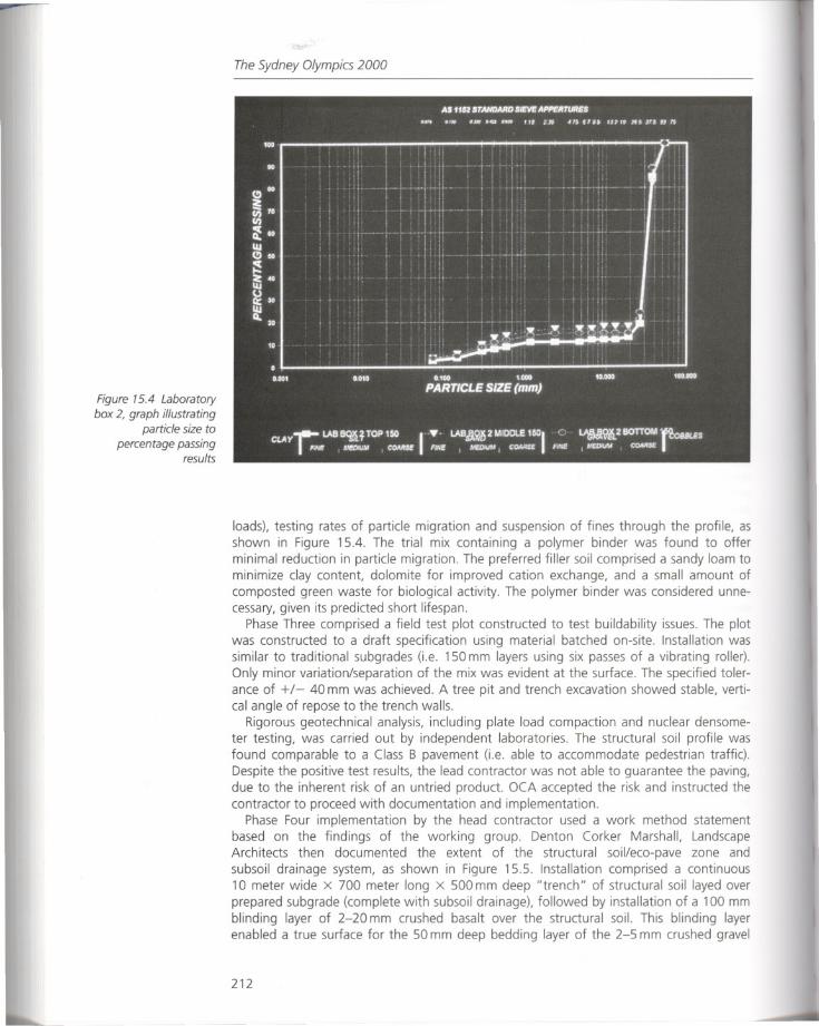
Figure 15.4 Laboratory
box 2, graph illustrating
particle size to
percentage passingresults
The Sydney Olympics 2000
loads), testing rates of particle migration and suspension of fines through the profile, asshown in Figure 15.4. The trial mix containing a polymer binder was found to offerminimal reduction in particle migration. The preferred filler soil comprised a sandy loam tominimize clay content, dolomite for improved cation exchange, and a small amount ofcom posted green waste for biological activity. The polymer binder was considered unnecessary, given its predicted short lifespan.
Phase Three comprised a field test plot constructed to test buildability issues. The plotwas constructed to a draft specification using material batched on-site. Installation wassimilar to traditional subgrades (i.e. 150 mm layers using six passes of a vibrating roller).Only minor variation/separation of the mix was evident at the surface. The specified tolerance of +/- 40 mm was achieved. A tree pit and trench excavation showed stable, vertical angle of repose to the trench walls.
Rigorous geotechnical analysis, including plate load compaction and nuclear densometer testing, was carried out by independent laboratories. The structural soil profile wasfound comparable to a Class B pavement (i.e. able to accommodate pedestrian traffic).Despite the positive test results, the lead contractor was not able to guarantee the paving,due to the inherent risk of an untried product. OCA accepted the risk and instructed thecontractor to proceed with documentation and implementation.
Phase Four implementation by the head contractor used a work method statementbased on the findings of the working group. Denton Corker Marshall, LandscapeArchitects then documented the extent of the structural soil/eco-pave zone andsubsoil drainage system, as shown in Figure 15.5. Installation comprised a continuous10 meter wide x 700 meter long x 500 mm deep "trench" of structural soil layed overprepared subgrade (complete with subsoil drainage), followed by installation of a 100 mmblinding layer of 2-20 mm crushed basalt over the structural soil. This blinding layerenabled a true surface for the 50 mm deep bedding layer of the 2-5 mm crushed gravel
212
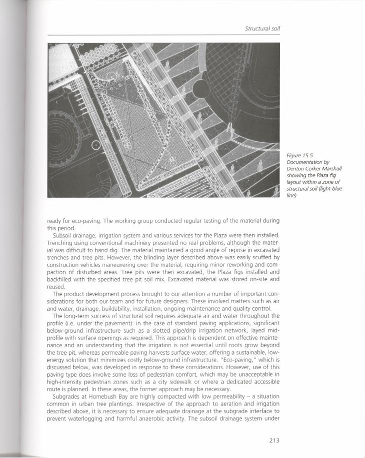
Structural soil
ready for eco-paving. The working group conducted regular testing of the material duringthis period.
Subsoil drainage, irrigation system and various services for the Plaza were then installed.Trenching using conventional machinery presented no real problems, although the material was difficult to hand dig. The material maintained a good angle of repose in excavatedtrenches and tree pits. However, the blinding layer described above was easily scuffed byconstruction vehicles maneuvering over the material, requiring minor reworking and compaction of disturbed areas. Tree pits were then excavated, the Plaza figs installed andbackfilled with the specified tree pit soil mix. Excavated material was stored on-site andreused.
The product development process brought to our attention a number of important considerations for both our team and for future designers. These involved matters such as airand water, drainage, buildability, installation, ongoing maintenance and quality control.
The long-term success of structural soil requires adequate air and water throughout theprofile (i.e. under the pavement): in the case of standard paving applications, significantbelow-ground infrastructure such as a slotted pipe/drip irrigation network, layed midprofile with surface openings as required. This approach is dependent on effective maintenance and an understanding that the irrigation is not essential until roots grow beyondthe tree pit, whereas permeable paving harvests surface water, offering a sustainable, lowenergy solution that minimizes costly below-ground infrastructure. "Eco-paving," which isdiscussed below, was developed in response to these considerations. However, use of thispaving type does involve some loss of pedestrian comfort, which may be unacceptable inhigh-intensity pedestrian zones such as a city sidewalk or where a dedicated accessibleroute is planned. In these areas, the former approach may be necessary.
Subgrades at Homebush Bay are highly compacted with low permeability - a situationcommon in urban tree plantings. Irrespective of the approach to aeration and irrigationdescribed above, it is necessary to ensure adequate drainage at the subgrade interface toprevent waterlogging and harmful anaerobic activity. The subsoil drainage system under
213
Figure 15.5Documentation byDenton Corker Marshall
showing the Plaza figlayout within a zone ofstructural soil (light-blueline)
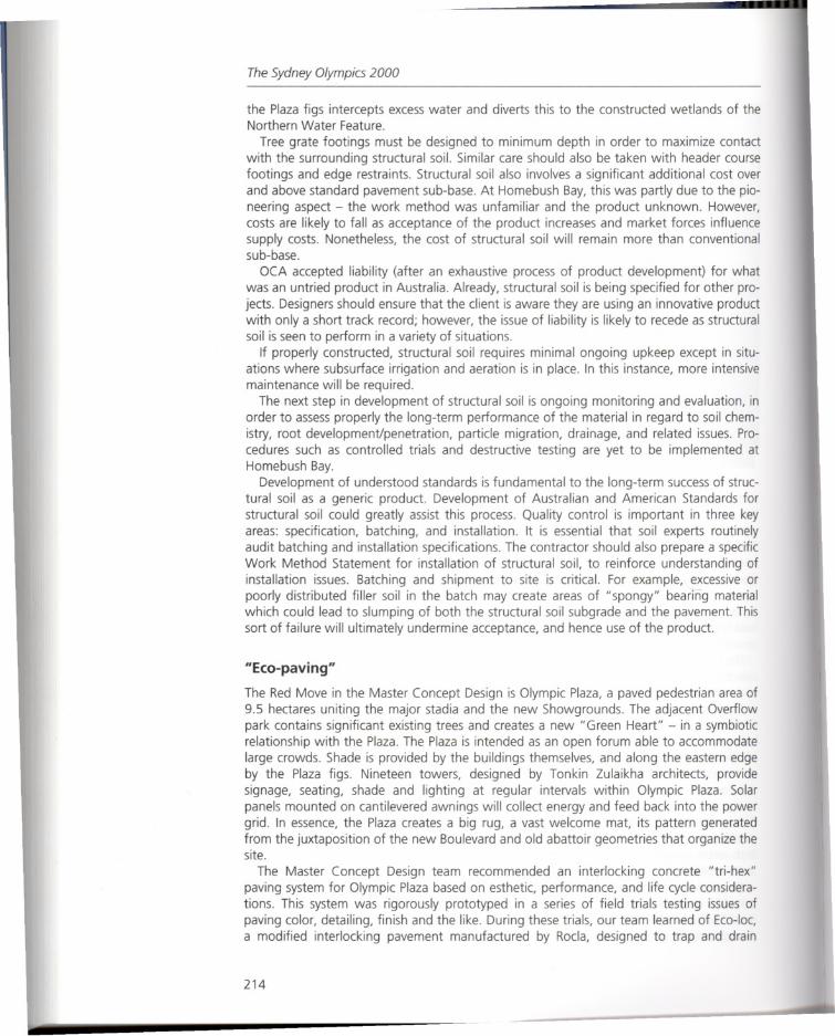
The Sydney Olympics 2000
the Plaza figs intercepts excess water and diverts this to the constructed wetlands of theNorthern Water Feature.
Tree grate footings must be designed to minimum depth in order to maximize contactwith the surrounding structural soil. Similar care should also be taken with header coursefootings and edge restraints. Structural soil also involves a significant additional cost overand above standard pavement sub-base. At Homebush Bay, this was partly due to the pioneering aspect - the work method was unfamiliar and the product unknown. However,costs are likely to fall as acceptance of the product increases and market forces influencesupply costs. Nonetheless, the cost of structural soil will remain more than conventionalsub-base.
OCA accepted liability (after an exhaustive process of product development) for whatwas an untried product in Australia. Already, structural soil is being specified for other projects. Designers should ensure that the client is aware they are using an innovative productwith only a short track record; however, the issue of liability is likely to recede as structuralsoil is seen to perform in a variety of situations.
If properly constructed, structural soil requires minimal ongoing upkeep except in situations where subsurface irrigation and aeration is in place. In this instance, more intensivemaintenance will be required.
The next step in development of structural soil is ongoing monitoring and evaluation, inorder to assess properly the long-term performance of the material in regard to soil chemistry, root development/penetration, particle migration, drainage, and related issues. Procedures such as controlled trials and destructive testing are yet to be implemented atHomebush Bay.
Development of understood standards is fundamental to the long-term success of structural soil as a generic product. Development of Australian and American Standards forstructural soil could greatly assist this process. Quality control is important in three keyareas: specification, batching, and installation. It is essential that soil experts routinelyaudit batching and installation specifications. The contractor should also prepare a specificWork Method Statement for installation of structural soil, to reinforce understanding ofinstallation issues. Batching and shipment to site is critical. For example, excessive orpoorly distributed filler soil in the batch may create areas of "spongy" bearing materialwhich could lead to slumping of both the structural soil subgrade and the pavement. Thissort of failure will ultimately undermine acceptance, and hence use of the product.
"Eco-paving"
The Red Move in the Master Concept Design is Olympic Plaza, a paved pedestrian area of9.5 hectares uniting the major stadia and the new Showgrounds. The adjacent Overflowpark contains significant existing trees and creates a new "Green Heart" - in a symbioticrelationship with the Plaza. The Plaza is intended as an open forum able to accommodatelarge crowds. Shade is provided by the buildings themselves, and along the eastern edgeby the Plaza figs. Nineteen towers, designed by Tonkin Zulaikha architects, providesignage, seating, shade and lighting at regular intervals within Olympic Plaza. Solarpanels mounted on cantilevered awnings will collect energy and feed back into the powergrid. In essence, the Plaza creates a big rug, a vast welcome mat, its pattern generatedfrom the juxtaposition of the new Boulevard and old abattoir geometries that organize thesite.
The Master Concept Design team recommended an interlocking concrete "tri-hex"paving system for Olympic Plaza based on esthetic, performance, and life cycle considerations. This system was rigorously prototyped in a series of field trials testing issues ofpaving color, detailing, finish and the like. During these trials, our team learned of Eco-Ioc,a modified interlocking pavement manufactured by Rocla, designed to trap and drain
214
"Eco-paving"
water. A sample of this product was subsequently included in the paving trials but wasfound to be unsuitable for pedestrian use.
However, the principle was sound, so we worked with Rocla to develop a new "ecopaver" shape as a modular component of our preferred tri-hex paving system. Roclaresponded by producing a small sample panel of the first eco-tri-hex prototype, hand cutfrom standard tri-hex pavers then installed in the paving field trial to test pedestriancomfort and pattern issues. This eco-tri-hex shape created a perforated field of paving,harvesting rainwater via a surface of small drainage holes, each filled with 2-5 mm gravel.Preliminary calculations indicated a water infiltration rate equal to a ten-minute storm witha recurrence interval of six months (Sydney conditions). Further eco-tri-hex were cut andlaid over the structural soil field trial to test buildability of the 2-20 mm blinding layer and2-5 mm bedding layer. The bedding layers and paving, as installed by the contractor,proved to be a relatively simple procedure. Engineering analysis indicated the eco-trihex/structural soil paving system was structurally adequate for light traffic load of 2 x10⁵ ESAover twenty years. The paving system was approved by OCA and is now installed,as shown in Figures 15.6 and 15.7.
215
Figure 15.6 Completedeco-tri-hex paving
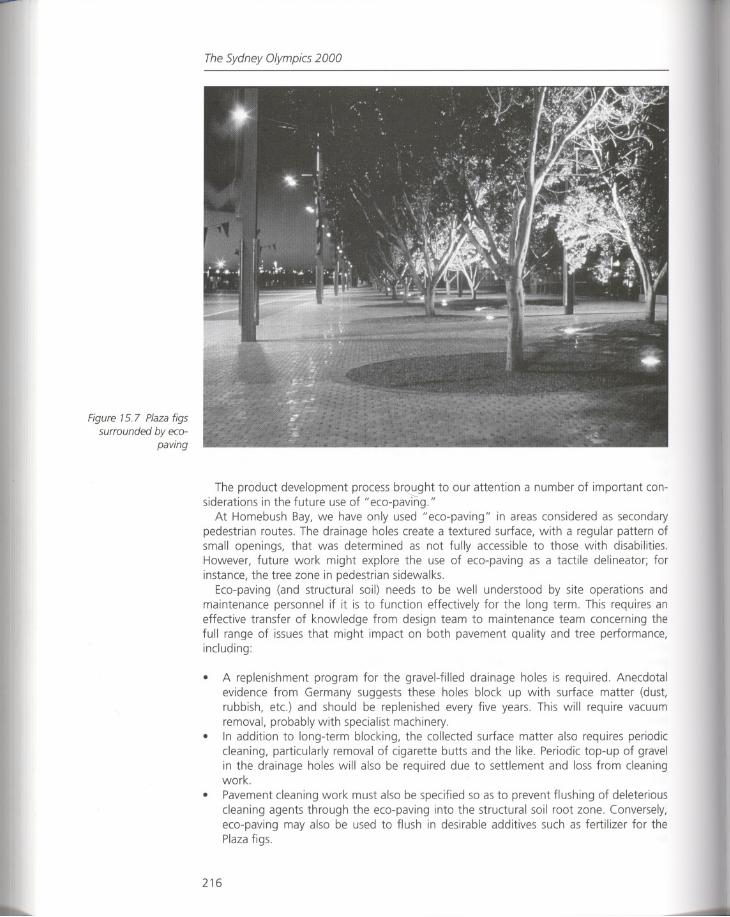
Figure 15.7 Plaza figssurrounded by eco
paving
The Sydney Olympics 2000
The product development process brought to our attention a number of important considerations in the future use of "eco-pavmg."
At Homebush Bay, we have only used "eco-paving" in areas considered as secondarypedestrian routes. The drainage holes create a textured surface, with a regular pattern ofsmall openings, that was determined as not fully accessible to those with disabilities.However, future work might explore the use of eco-paving as a tactile delineator; forinstance, the tree zone in pedestrian sidewalks.
Eco-paving (and structural soil) needs to be well understood by site operations andmaintenance personnel if it is to function effectively for the long term. This requires aneffective transfer of knowledge from design team to maintenance team concerning thefull range of issues that might impact on both pavement quality and tree performance,including:
• A replenishment program for the gravel-filled drainage holes is required. Anecdotalevidence from Germany suggests these holes block up with surface matter (dust,rubbish, etc.) and should be replenished every five years. This will require vacuumremoval, probably with specialist machinery.
• In addition to long-term blocking, the collected surface matter also requires periodiccleaning, particularly removal of cigarette butts and the like. Periodic top-up of gravelin the drainage holes will also be required due to settlement and loss from cleaningwork.
• Pavement cleaning work must also be specified so as to prevent flushing of deleteriouscleaning agents through the eco-paving into the structural soil root zone. Conversely,eco-paving may also be used to flush in desirable additives such as fertilizer for thePlaza figs.
216
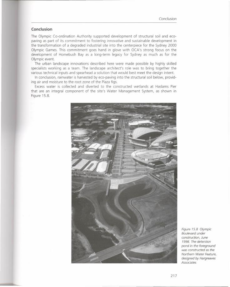
Conclusion
Conclusion
The Olympic Co-ordination Authority supported development of structural soil and ecopaving as part of its commitment to fostering innovative and sustainable development inthe transformation of a degraded industrial site into the centerpiece for the Sydney 2000Olympic Games. This commitment goes hand in glove with OCA's strong focus on thedevelopment of Homebush Bay as a long-term legacy for Sydney as much as for theOlympic event.
The urban landscape innovations described here were made possible by highly skilledspecialists working as a team. The landscape architect's role was to bring together thevarious technical inputs and spearhead a solution that would best meet the design intent.
In conclusion, rainwater is harvested by eco-paving into the structural soil below, providing air and moisture to the root zone of the Plaza figs.
Excess water is collected and diverted to the constructed wetlands at Haslams Pier
that are an integral component of the site's Water Management System, as shown inFigure 15.8.
217
Figure 15.8 OlympicBoulevard under
construction, June1998. The detention
pond in the foregroundwas constructed as the
Northern Water Feature,
designed by HargreavesAssociates

The Sydney Olympics 2000
References
Grabosky, Jason and Nina Bassuk (1995) Progress on the Development of an Urban Tree Soil Specification, Ithaca, N.Y.: Cornell University, Urban Horticulture Institute.
Lindsey, Patricia (1994) The Design of Structural Soil Mixes for Trees in Urban Areas, Growing Points,Davis: University of California.
218
Response
RESPONSE
Environmental site design as public infrastructure?
The Sydney Olympics, the "Green Games," is reclaiming a post-industrial wasteland with acomprehensive system of environmentally responsible, sustainable technologies. The useof structural soil and" eco-paving" are innovations that unite the landscape systems operating on the site. An immense plaza that facilitates the huge numbers of visitors has beendesigned to address the basic biological needs of its trees, while integrating excess waterinto cleansing wetlands. This integration of urban tree planting research with the site'swater management system is a prototype for biological systems and urban infrastructureworking together to enhance city life.
The typical condition, however, for trees in the city is that they die at an alarming rate;in the United States the average life of a street tree is seven years. It is only recently thatthe reasons for their short life span have become known. These trees die because theirbasic biology has not been well understood; consequently, tree planting technologies haverarely started from the tree's fundamental requirements. In contrast, the Sydney project isutilizing current information to start from the trees' needs for appropriate soil, water, andair.
Research into tree root systems is quite new. The notion that a tree's roots are a mirrorimage of their canopy has been dispelled: 90 percent of a tree's roots are in the top 24inches of soil, and a tree's roots spread far beyond their drip line. Recent researchdeveloped by landscape architect James Urban and others has concluded that soil volumeis the key factor in long-term survival for urban trees:
The actual amount of soil that the tree needs should be calculated by measuring thearea within the projected mature drip line of the tree. A rougn rule of thumb is toprovide one cubic foot of usable soil for every two square feet of mature canopyvolume ... Studies on the East Coast suggest that providing approximately 400 cubicfeet of soil per tree will usually provide sufficient growing room if the other soil in thearea has some capacity for root development.
(Urban 1996: 96)
This is a huge departure from the conventional design for trees in pavement which typically shows a 4 foot x 4 foot tree pit, resulting in a tree pit volume of approximately 48cubic feet. This tree pit detail can work fine for a tree planted in lawn as this tree has adjacent soil to utilize for root expansion. Trees in the city typically have no adjacent source ofhealthy soil.
The fig trees in Olympic Plaza are in pits approximately 15 feet in diameter - muchlarger than a conventional design would specify - which promises healthier trees.Although the tree pits are not interconnected, the structural soil is in a continuous trench.This strategy employs recent research that has found that trees growing in interconnectedsoil volumes grow larger than they would if planted individually. Interconnected soilscreate the conditions for a more even distribution of water and roots (Urban 1996: 96).
Developing, testing. and implementing the new technologies of structural soils and"eco-paving" at Sydney was the result of a very effective collaboration between landscapearchitects and scientists. However developing these new technologies is also expensive.The fact that these products/systems were virtually unknown in Australia highlights theimportance of the "Green Games" to bring new technologies into the mainstream. TheAustralian government underwrote the cost of research and development, and assumed
219
The Sydney Olympics 2000
the liability for these innovative technologies. It is highly unlikely that any private developeror individual city would have been willing to take on these kinds of expenses and risks.The Olympics provide an incentive for experimentation. The world observes the hostcountry's efforts to create both a setting and an image, in this case, an environmentallyresponsible one.
The Sydney Olympics utilized the latest data to construct a "manufactured system" fortrees to thrive surrounded by pavement. Trees that are used as urban street trees are typically forest climax species, and when these trees are planted in the city they require infrastructure to succeed. It may be argued that the trees themselves are infrastructure, asimportant to urban life as the utility systems and roads, especially if we consider thatplants sustain life on earth by producing oxygen and removing carbon dioxide. Treesprovide shade, cooling city streets, and the myriad esthetic qualities of trees - theirtexture, form, color, and scent contribute profoundly to the quality of urban life.
The line of figs at Olympic Plaza represents the human impulse to control nature.Although technical innovations will support the figs, there is ample reason for their presence. The trees provide much-needed shade along the eastern edge of the Plaza, linkingthe railway station with recreational centers. The figs serve as an element of human scale,working as a foil to the architecture and the Plaza. The matched specimens will be stunning, but they will probably reach the end of their life span together. Then what willhappen? Many would argue to simply replant with new trees of the same species, which isof course viable. Allees and groves of the same species are ancient forms of plantingdesign, and it would be a great loss if they disappeared from our cities due to a fear ofplanting monocultures.
A new paradigm for street tree planting is emerging in Europe which utilizes the idea ofplants as systems. In the Netherlands, street trees are increasingly being thought of interms of an urban forest. Fast-growing pioneer species are planted at the same time asslow-growing climax species. The pioneer species are pruned upward to allow the climaxspecies room to develop. The goal is to have a variety of trees and ages of trees on thesite, providing continual canopy in a more sustainable way,/while providing an opportunityfor city residents to become more aware of the natural processes of growth and succession (Hough Date 1995).
It is valid to see plants as sculptures and to see plants as systems. At the SydneyOlympics, both points of view are visible: a monoculture of mature figs in pavement aswell as cleansing wetlands where communities of plants cleanse stormwater of toxins. The"Green Games" provides a new view of urban design, where a city may be built by starting from an understanding of natural processes, then integrating human use into theseprocesses. This synthesis of technology, science, and design is of the utmost importance inthe redesign of post-industrial, or "manufactured sites," where remediation of soil andwater must be the starting point for design.
References
Hough, Michael (Date 1995) Cities and Natural Process, London and New York: Routledge.Urban, James (1996) "Room to Grow," Landscape Architecture (March), pp. 74-97.
220
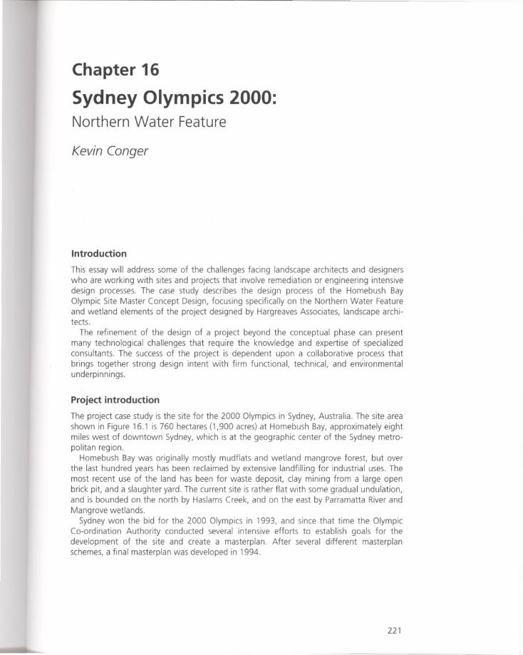
Chapter 16
Sydney Olympics 2000:Northern Water Feature
Kevin Conger
Introduction
This essay will address some of the challenges facing landscape architects and designerswho are working with sites and projects that involve remediation or engineering intensivedesign processes. The case study describes the design process of the Homebush BayOlympic Site Master Concept Design, focusing specifically on the Northern Water Featureand wetland elements of the project designed by Hargreaves Associates, landscape architects.
The refinement of the design of a project beyond the conceptual phase can presentmany technological challenges that require the knowledge and expertise of specializedconsultants. The success of the project is dependent upon a collaborative process thatbrings together strong design intent with firm functional, technical, and en1ironmentalunderpinnings.
Project introduction
The project case study is the site for the 2000 Olympics in Sydney, Australia. The site areashown in Figure 16.1 is 760 hectares (1,900 acres) at Homebush Bay, approximately eightmiles west of downtown Sydney, which is at the geographic center of the Sydney metropolitan region.
Homebush Bay was originally mostly mudflats and wetland mangrove forest, but overthe last hundred years has been reclaimed by extensive landfilling for industrial uses. Themost recent use of the land has been for waste deposit, clay mining from a large openbrick pit, and a slaughter yard. The current site is rather flat with some gradual undulation,and is bounded on the north by Haslams Creek, and on the east by Parramatta River andMangrove wetlands.
Sydney won the bid for the 2000 Olympics in 1993, and since that time the OlympicCo-ordination Authority conducted several intensive efforts to establish goals for thedevelopment of the site and create a masterplan. After several different masterplanschemes, a final masterplan was developed in 1994.
221
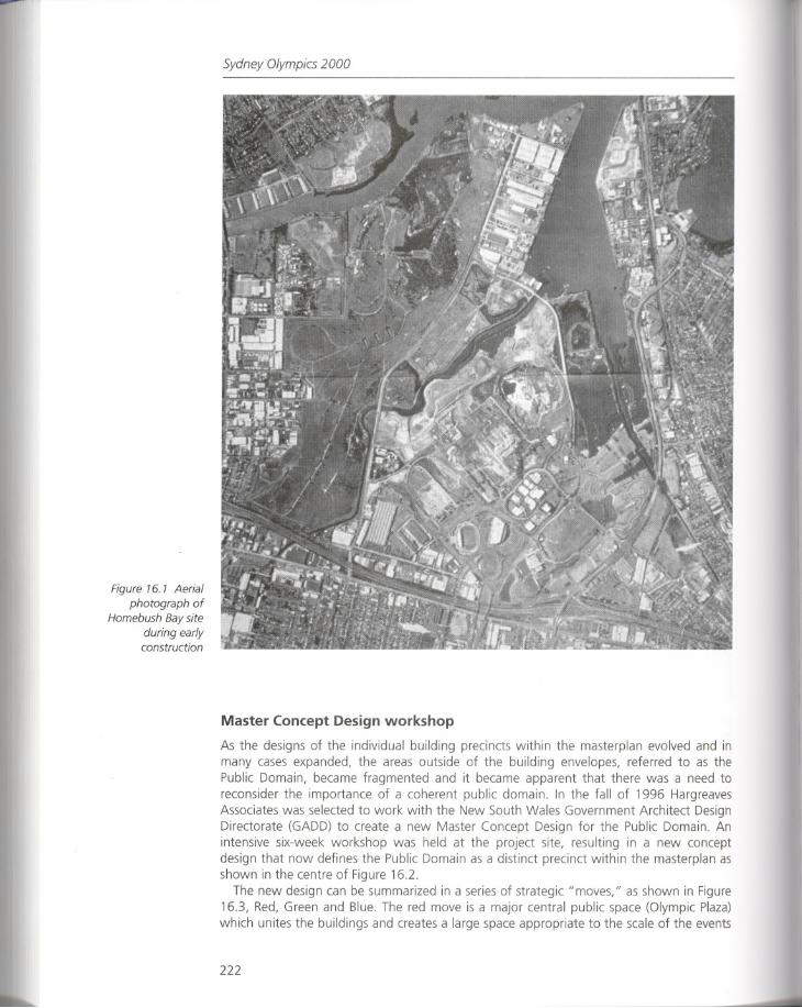
Figure 16. 1 Aerial
photograph ofHomebush Bay site
during earlyconstruction
Sydney Olympics 2000
Master Concept Design workshop
As the designs of the individual building precincts within the masterplan evolved and inmany cases expanded, the areas outside of the building envelopes, referred to as thePublic Domain, became fragmented and it became apparent that there was a need toreconsider the importance of a coherent public domain. In the fall of 1996 HargreavesAssociates was selected to work with the New South Wales Government Architect DesignDirectorate (GAD D) to create a new Master Concept Design for the Public Domain. Anintensive six-week workshop was held at the project site, resulting in a new conceptdesign that now defines the Public Domain as a distinct precinct within the masterplan asshown in the centre of Figure 16.2.
The new design can be summarized in a series of strategic" moves," as shown in Figure16.3, Red, Green and Blue. The red move is a major central public space (Olympic Plaza)which unites the buildings and creates a large space appropriate to the scale of the events
222
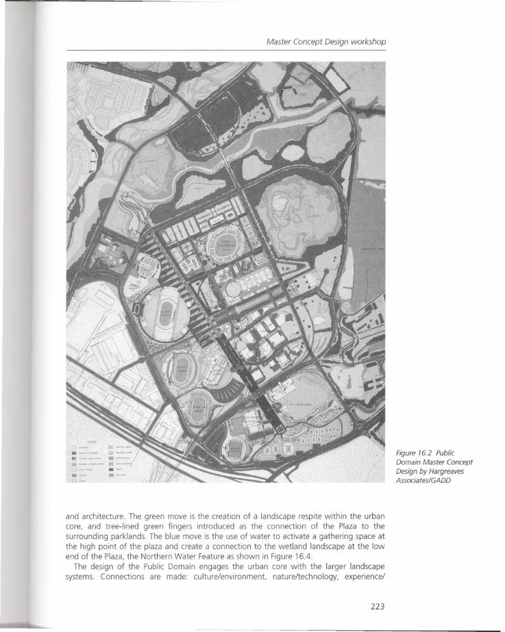
Master Concept Design workshop
and architecture. The green move is the creation of a landscape respite within the urbancore, and tree-lined green fingers introduced as the connection of the Plaza to thesurrounding parklands. The blue move is the use of water to activate a gathering space atthe high point of the plaza and create a connection to the wetland landscape at the lowend of the Plaza, the Northern Water Feature as shown in Figure 16.4.
The design of the Public Domain engages the urban core with the larger landscapesystems. Connections are made: culture/environment, nature/technology, experience/
223
Figure 16.2 PublicDomain Master ConceptDesign by HargreavesAssociates/GADD
Figure 16.3 "Red,Green, and Blue Moves"
which give identity anddefinition to the Public
Domain
Sydney Olympics 2000
224
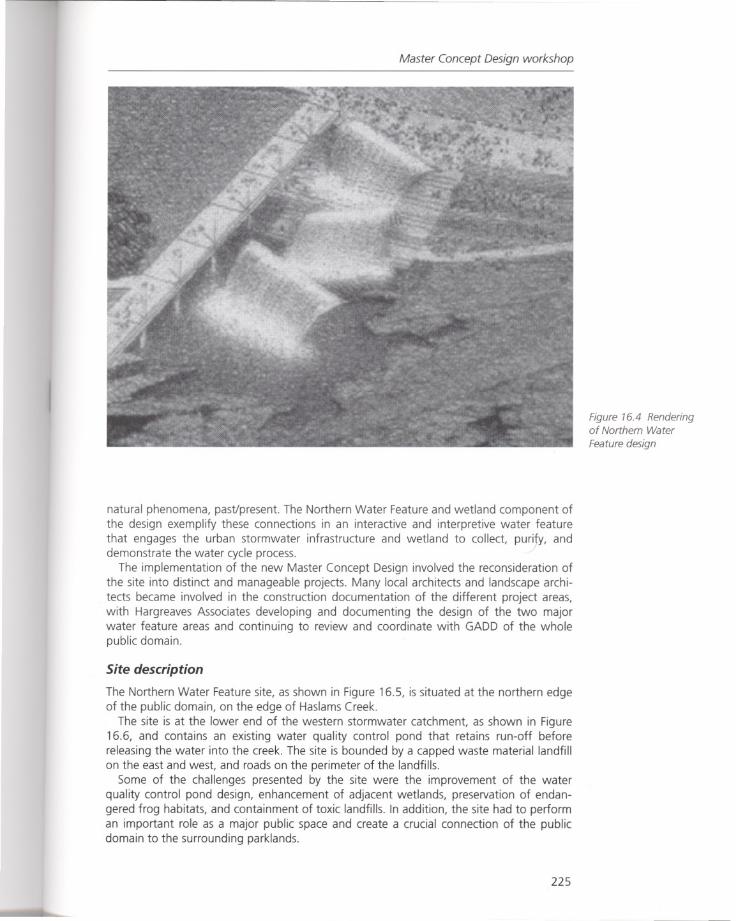
Master Concept Design workshop
natural phenomena, pasVpresent. The Northern Water Feature and wetland component ofthe design exemplify these connections in an interactive and interpretive water feature
that engages the urban stormwater infrastructure and wetland to collect, pur1Y, anddemonstrate the water cycle process.
The implementation of the new Master Concept Design involved the reconsideration ofthe site into distinct and manageable projects. Many local architects and landscape architects became involved in the construction documentation of the different project areas,with Hargreaves Associates developing and documenting the design of the two majorwater feature areas and continuing to review and coordinate with GADD of the wholepublic domain.
Site description
The Northern Water Feature site, as shown in Figure 16.5, is situated at the northern edgeof the public domain, on the edge of Haslams Creek.
The site is at the lower end of the western stormwater catchment, as shown in Figure16.6, and contains an existing water quality control pond that retains run-off beforereleasing the water into the creek. The site is bounded by a capped waste material landfillon the east and west, and roads on the perimeter of the landfills.
Some of the challenges presented by the site were the improvement of the waterquality control pond design, enhancement of adjacent wetlands, preservation of endangered frog habitats, and containment of toxic landfills. In addition, the site had to performan important role as a major public space and create a crucial connection of the publicdomain to the surrounding parklands.
225
Figure 76.4 Renderingof Northern Water
Feature design
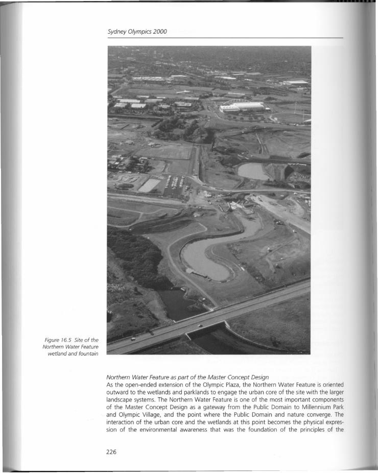
Figure 16.5 Site of theNorthern Water Feature
wetland and fountain
Sydney Olympics 2000
Northern Water Feature as part of the Master Concept DesignAs the open-ended extension of the Olympic Plaza, the Northern Water Feature is orientedoutward to the wetlands and parklands to engage the urban core of the site with the largerlandscape systems. The Northern Water Feature is one of the most important componentsof the Master Concept Design as a gateway from the Public Domain to Millennium Parkand Olympic Village, and the point where the Public Domain and nature converge. Theinteraction of the urban core and the wetlands at this point becomes the physical expression of the environmental awareness that was the foundation of the principles of the
226
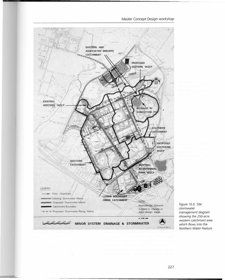
Master Concept Design workshop
MINOR SYSTEM DRAINAGE & STORMWATER
LEGEND
Flow Directions
ExIsting Stormwater Mairs_ Proposed Stormwater Mains
_ Catchment Boundary
_ Proposed Stormwater Rising Mains.
tOO 200 3bO 40' 5"
/1
NO ;
Approxitnate etwcrK.
Sub)oot to change ,ndetail desIgn stage.
,......-
227
Figure 16.6 Sitestormwater
management diagram
showing the 2SD-acrewestern catchment areawhich flows into the
Northern Water Feature
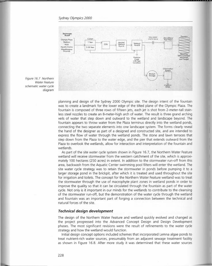
Figure 16.7 NorthernWater Feature
schematic water cyclediagram
Sydney Olympics 2000--Ofrmpc PIa",
Soac5um
MlJA
AqucmcC.,h
Mixol_G<ounds
planning and design of the Sydney 2000 Olympic site. The design intent of the fountainwas to create a landmark for the lower edge of the tilted plane of the Olympic Plaza. Thefountain is composed of three rows of fifteen jets, each jet is shot from 2-meter-tall stainless steel nozzles to create an 8-meter-high arch of water. The result is three grand archingveils of water that step down and outward to the wetland and landscape beyond. Thefountain appears to throw water from the Plaza terminus directly into the wetland ponds,connecting the two separate elements into one landscape system. The forms clearly revealthe hand of the designer as part of a designed and constructed site, and are intended toexpress the flow of water through the wetland ponds. The stone and lawn terraces thatstep down from the Plaza to the water edge, and the pier that extends outward from thePlaza to overlook the wetlands, allow for interaction and interpretation of the fountain andwetlands.
As part of the site water cycle system shown in Figure 16.7, the Northern Water Featurewetland will receive stormwater from the western catchment of the site, which is approximately 100 hectares (250 acres) in extent. In addition to the stormwater run-off from thisarea, backwash from the Aquatic Center swimming pool filters will enter the wetland. Thesite water cycle strategy was to retain the stormwater in ponds before pumping it to alarger storage pond in the brickpit, after which it is treated and used throughout the sitefor irrigation and toilets. The concept for the Northern Water Feature wetland was to treatthe stormwater through the use of macrophyte plant zones in wetland ponds in order toimprove the quality so that it can be circulated through the fountain as part of the watercycle. Not only is it important in our minds for the wetlands to contribute to the cleansingof the stormwater run-off, but the demonstration of the water cycle through the wetlandand fountain was an important part of forging a connection between the technical andnatural forces of the site.
Technical design development
The design of the Northern Water Feature and wetland quickly evolved and changed asthe project progressed into the Advanced Concept Design and Design Developmentphases. The most significant revisions were the result of refinements to the water cyclestrategy and how the wetland would function.
Initial design concept options included schemes that incorporated Lemna algae ponds totreat nutrient-rich water sources, presumably from an adjacent sewage treatment facilityas shown in Figure 16.8. After more study it was determined that these water sources
228
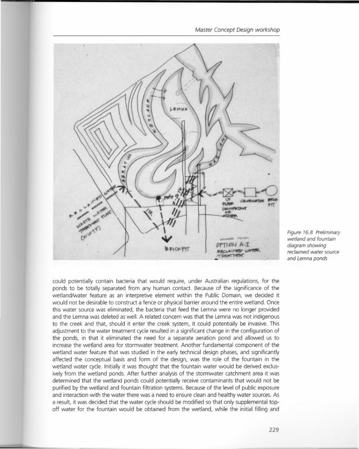
Master Concept Design workshop
OrTIOJ-.J A-I~\MelP~
.;...
could potentially contain bacteria that would require, under Australian regulations, for theponds to be totally separated from any human contact. Because of the significance of thewetlandtwater feature as an interpretive element within the Public Domain, we decided itwould not be desirable to construct a fence or physical barrier around the entire wetland. Oncethis water source was eliminated, the bacteria that feed the Lemna were no longer providedand the Lemna was deleted as well. A related concern was that the Lemna was not indigenousto the creek and that, should it enter the creek system, it could potentially be invasive. Thisadjustment to the water treatment cycle resulted in a significant change in the configuration ofthe ponds, in that it eliminated the need for a separate aeration pond and allowed us toincrease the wetland area for stormwater treatment. Another fundamental component of thewetland water feature that was studied in the early technical design phases, and significantlyaffected the conceptual basis and form of the design, was the role of the fountain in thewetland water cycle. Initially it was thought that the fountain water would be derived exclusively from the wetland ponds. After further analysis of the stormwater catchment area it wasdetermined that the wetland ponds could potentially receive contaminants that would not bepurified by the wetland and fountain filtration systems. Becauseof the level of public exposureand interaction with the water there was a need to ensure clean and healthy water sources. Asa result, it was decided that the water cycle should be modified so that only supplemental topoff water for the fountain would be obtained from the wetland, while the initial filling and
229
Figure 16.8 Preliminarywetland and fountain
diagram showingreclaimed water source
and Lemna ponds
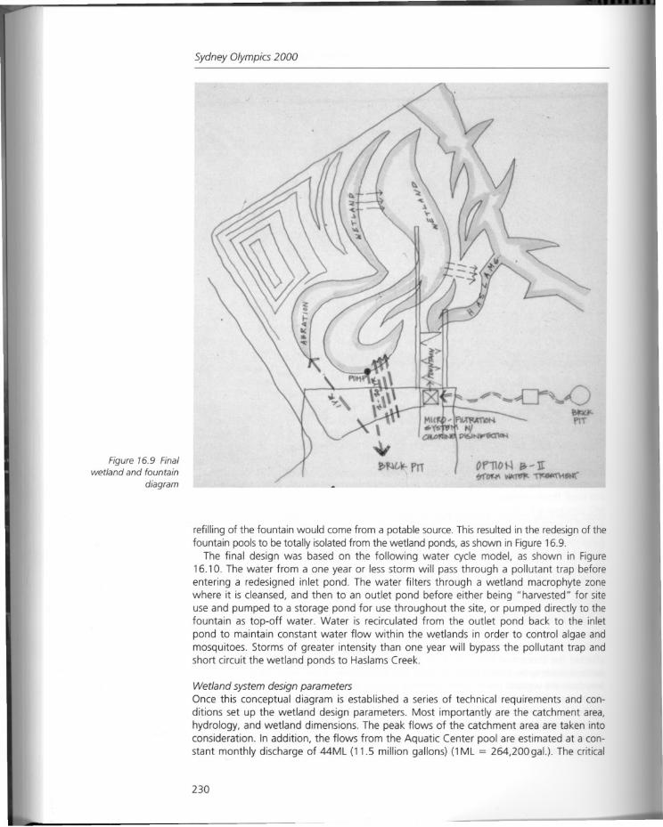
Figure 16.9 Finalwetland and fountain
diagram
Sydney Olympics 2000
refilling of the fountain would come from a potable source. This resulted in the redesign of thefountain pools to be totally isolated from the wetland ponds, as shown in Figure 16.9.
The final design was based on the following water cycle model, as shown in Figure16.10. The water from a one year or less storm will pass through a pollutant trap beforeentering a redesigned inlet pond. The water filters through a wetland macrophyte zonewhere it is cleansed, and then to an outlet pond before either being" harvested" for siteuse and pumped to a storage pond for use throughout the site, or pumped directly to thefountain as top-off water. Water is recirculated from the outlet pond back to the inletpond to maintain constant water flow within the wetlands in order to control algae andmosquitoes. Storms of greater intensity than one year will bypass the pollutant trap andshort circuit the wetland ponds to Haslams Creek.
Wetland system design parametersOnce this conceptual diagram is established a series of technical requirements and conditions set up the wetland design parameters. Most importantly are the catchment area,hydrology, and wetland dimensions. The peak flows of the catchment area are taken intoconsideration. In addition, the flows from the Aquatic Center pool are estimated at a constant monthly discharge of 44ML (11.5 million gallons) (1ML = 264,200gal.). The critical
230
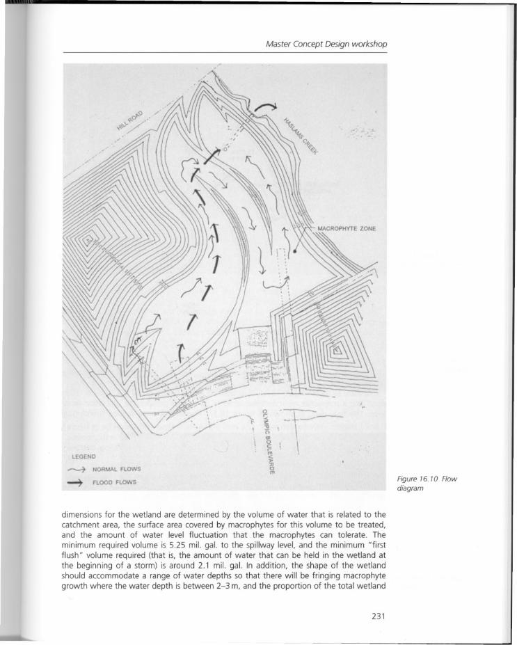
Master Concept Design workshop
,/
LEGEND
~ NORMAL FLOWS
~ FLOOD FLOWS
I'I
\
\
-----
Figure 16. 10 Flowdiagram
dimensions for the wetland are determined by the volume of water that is related to thecatchment area, the surface area covered by macrophytes for this volume to be treated,and the amount of water level fluctuation that the macrophytes can tolerate. Theminimum required volume is 5.25 mil. gal. to the spillway level, and the minimum "firstflush" volume required (that is, the amount of water that can be held in the wetland atthe beginning of a storm) is around 2.1 mil. gal. In addition, the shape of the wetlandshould accommodate a range of water depths so that there will be fringing macrophytegrowth where the water depth is between 2-3 m, and the proportion of the total wetland
231
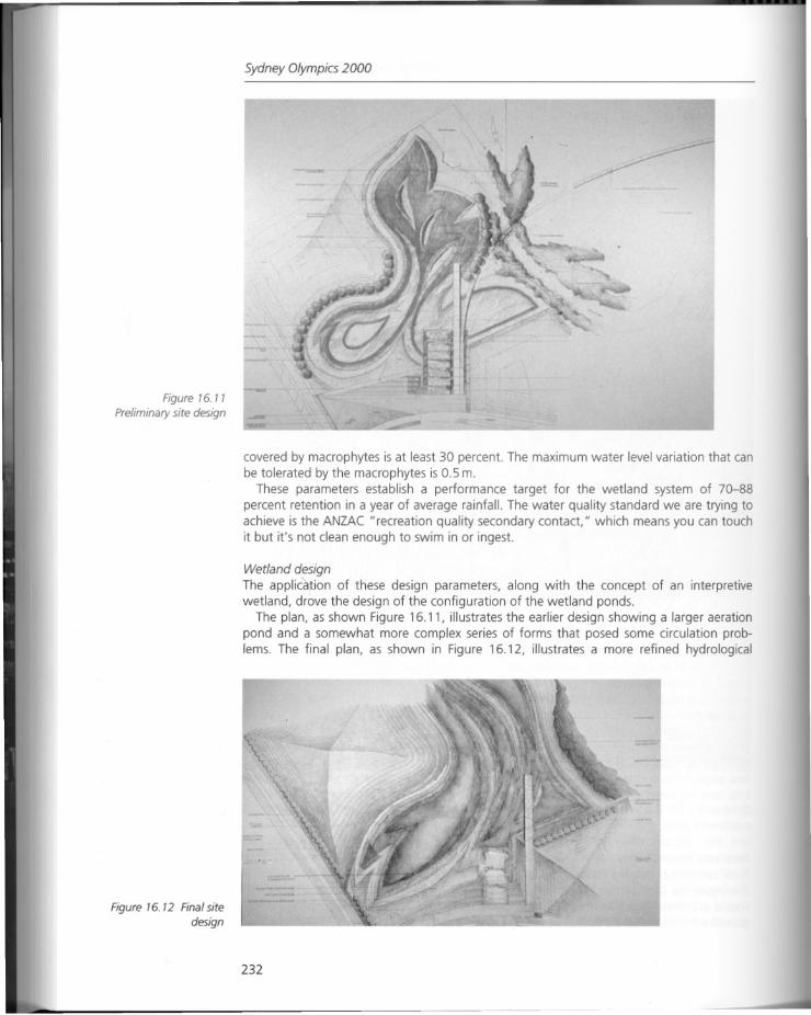
Figure 76. 7 7
Preliminary site design
Figure 76. 72 Final sitedesign
Sydney Olympics 2000
covered by macrophytes is at least 30 percent. The maximum water level variation that canbe tolerated by the macrophytes is 0.5 m.
These parameters establish a performance target for the wetland system of 70-88percent retention in a year of average rainfall. The water quality standard we are trying toachieve is the ANZAC "recreation quality secondary contact," which means you can touchit but it's not clean enough to swim in or ingest.
Wetland designThe application of these design parameters, along with the concept of an interpretivewetland, drove the design of the configuration of the wetland ponds.
The plan, as shown Figure 16.11, illustrates the earlier design showing a larger aerationpond and a somewhat more complex series of forms that posed some circulation problems. The final plan, as shown in Figure 16.12, illustrates a more refined hydrological
232
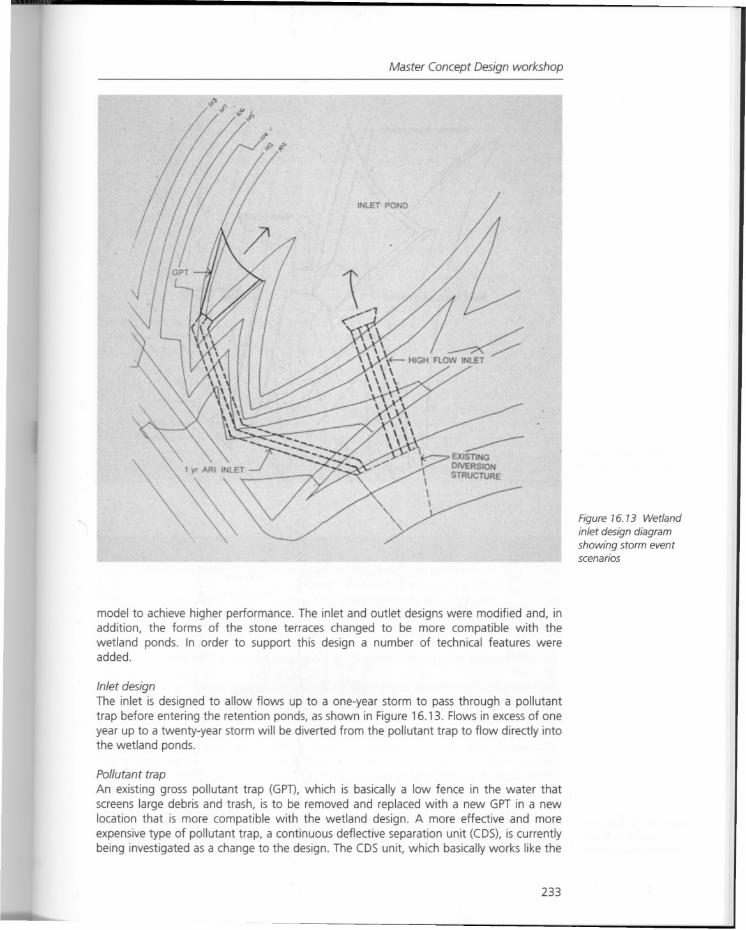
Master Concept Design workshop
model to achieve higher performance. The inlet and outlet designs were modified and, inaddition, the forms of the stone terraces changed to be more compatible with thewetland ponds. In order to support this design a number of technical features wereadded.
Inlet designThe inlet is designed to allow flows up to a one-year storm to pass through a pollutanttrap before entering the retention ponds, as shown in Figure 16.13. Flows in excess of oneyear up to a twenty-year storm will be diverted from the pollutant trap to flow directly intothe wetland ponds.
Pollutant trapAn existing gross pollutant trap (GPT), which is basically a low fence in the water thatscreens large debris and trash, is to be removed and replaced with a new GPT in a newlocation that is more compatible with the wetland design. A more effective and moreexpensive type of pollutant trap, a continuous deflective separation unit (CDS), is currentlybeing investigated as a change to the design. The CDS unit, which basically works like the
233
Figure 16. 13 Wetlandinlet design diagramshowing storm eventscenarios
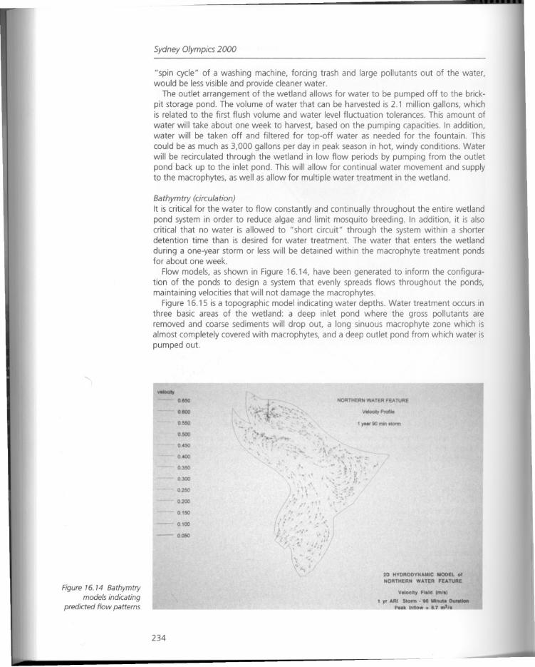
Sydney Olympics 2000
"spin cycle" of a washing machine, forcing trash and large pollutants out of the water,would be less visible and provide cleaner water.
The outlet arrangement of the wetland allows for water to be pumped off to the brickpit storage pond. The volume of water that can be harvested is 2.1 million gallons, whichis related to the first flush volume and water level fluctuation tolerances. This amount of
water will take about one week to harvest, based on the pumping capacities. In addition,water will be taken off and filtered for top-off water as needed for the fountain. Thiscould be as much as 3,000 gallons per day in peak season in hot, windy conditions. Waterwill be recirculated through the wetland in low flow periods by pumping from the outletpond back up to the inlet pond. This will allow for continual water movement and supplyto the macrophytes, as well as allow for multiple water treatment in the wetland.
Bathymtry (circulation)It is critical for the water to flow constantly and continually throughout the entire wetlandpond system in order to reduce algae and limit mosquito breeding. In addition, it is alsocritical that no water is allowed to "short circuit" through the system within a shorterdetention time than is desired for water treatment. The water that enters the wetland
during a one-year storm or less will be detained within the macrophyte treatment pondsfor about one week.
Flow models, as shown in Figure 16.14, have been generated to inform the configuration of the ponds to design a system that evenly spreads flows throughout the ponds,maintaining velocities that will not damage the macrophytes.
Figure 16.15 is a topographic model indicating water depths. Water treatment occurs inthree basic areas of the wetland: a deep inlet pond where the gross pollutants areremoved and coarse sediments will drop out, a long sinuous macrophyte zone which isalmost completely covered with macrophytes, and a deep outlet pond from which water ispumped out.
Figure 76. 74 Bathymtrymodels indicating
predicted flow patterns
o.tl5O
0.110O
o.~
0.500
o
D.~
0.:100
o.2SO
0.200
0. ISO
0. 100
-- 0.050
234
NORTHERN WATER FEATURE
VoIoatyProflJe
1 year 80 O'W'I .totm
20 HYDRODYNAMIC MODEL 01NORTHERN WATER FEATURE
Voloclty Flold (mlo)
1 yr ARI Stonn· to M'nutl O1JrattonP Inno. 1 'I. _
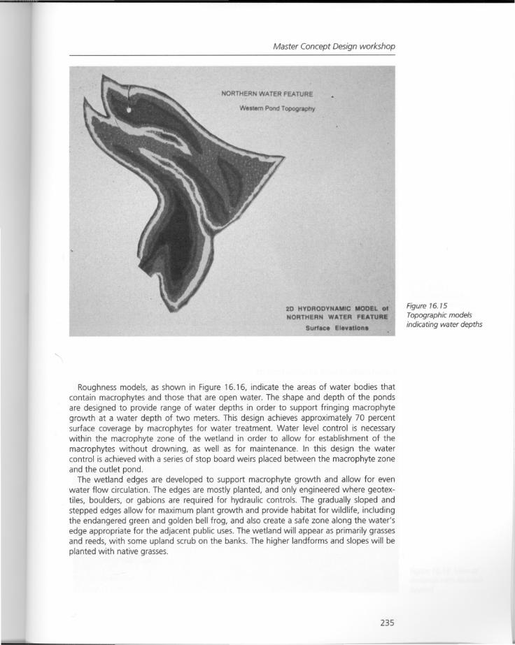
Master Concept Design workshop
NORTHERN WATER FEATURE
Westem Pond TopograpOy
20 HYDRODYNAMIC MODEL 01
NORTHERN WATER FEATURE
Sur1lee ElevlUon
Roughness models, as shown in Figure 16.16, indicate the areas of water bodies thatcontain macrophytes and those that are open water. The shape and depth of the pondsare designed to provide range of water depths in order to support fringing macrophytegrowth at a water depth of two meters. This design achieves approximately 70 percentsurface coverage by macrophytes for water treatment. Water level control is necessarywithin the macrophyte zone of the wetland in order to allow for establishment of themacrophytes without drowning, as well as for maintenance. In this design the watercontrol is achieved with a series of stop board weirs placed between the macrophyte zoneand the outlet pond.
The wetland edges are developed to support macrophyte growth and allow for evenwater flow circulation. The edges are mostly planted, and only engineered where geotextiles, boulders, or gabions are required for hydraulic controls. The gradually sloped andstepped edges allow for maximum plant growth and provide habitat for wildlife, includingthe endangered green and golden bell frog, and also create a safe zone along the water'sedge appropriate for the adjacent public uses. The wetland will appear as primarily grassesand reeds, with some upland scrub on the banks. The higher landforms and slopes will beplanted with native grasses.
235
Figure 16. 15
Topographic modelsindicating water depths
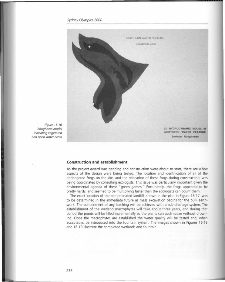
Figure 16. 16
Roughness modelindicating vegetated
and open water areas
Sydney Olympics 2000
RTH RNWAT RF ATU
z
20 HYDRODYNAMIC MOD l 01NORTHERN WATER FEATUR
Surf.C. RouQhn.
Construction and establishment
As the project award was pending and construction were about to start, there are a fewaspects of the design were being tested. The location and identification of all of theendangered frogs on the site, and the relocation of these frogs during construction, wasbeing coordinated by consulting ecologists. This issue was particularly important given theenvironmental agenda of these U green games. U Fortunately, the frogs appeared to bepretty hardy, and seemed to be multiplying faster than the ecologists can count them.
The exact location of the contaminated landfill, shown in the plan in Figure 16.17, wasto be determined in the immediate future as mass excavation begins for the bulk earthwork. The containment of any leaching will be achieved with a sub-drainage system. Theestablishment of the wetland macrophytes will take about three years, and during thatperiod the ponds will be filled incrementally so the plants can acclimatize without drowning. Once the macrophytes are established the water quality will be tested and, whenacceptable, be introduced into the fountain system. The images shown in Figures 16.18and 16.19 illustrate the completed wetlands and fountain.
236
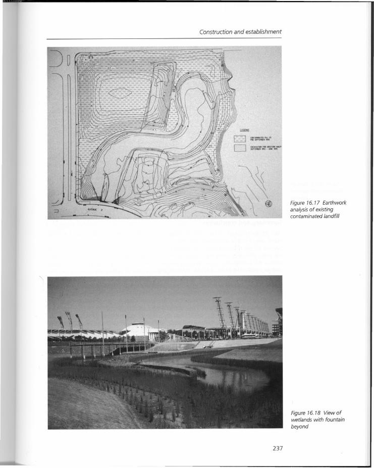
Jo
Construction and establishment
_ .....•• JIP'fMUI "'.
t nil...
Figure 16. 17 Earthworkanalysis of existingcontaminated landfill
237
Figure 16.18 View ofwetlands with fountain
beyond
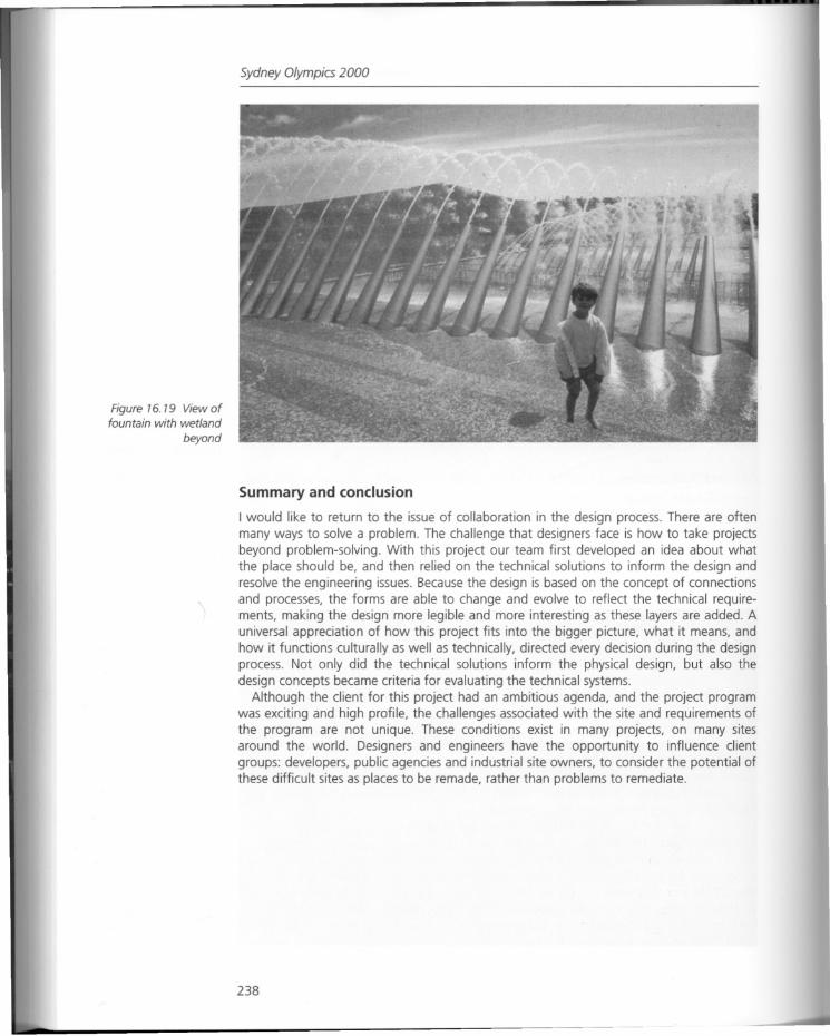
Figure 16. 19 View offountain with wetland
beyond
Sydney Olympics 2000
Summary and conclusion
I would like to return to the issue of collaboration in the design process. There are oftenmany ways to solve a problem. The challenge that designers face is how to take projectsbeyond problem-solving. With this project our team first developed an idea about whatthe place should be, and then relied on the technical solutions to inform the design andresolve the engineering issues. Because the design is based on the concept of connectionsand processes, the forms are able to change and evolve to reflect the technical requirements, making the design more legible and more interesting as these layers are added. Auniversal appreciation of how this project fits into the bigger picture, what it means, andhow it functions culturally as well as technically, directed every decision during the designprocess. Not only did the technical solutions inform the physical design, but also thedesign concepts became criteria for evaluating the technical systems.
Although the client for this project had an ambitious agenda, and the project programwas exciting and high profile, the challenges associated with the site and requirements ofthe program are not unique. These conditions exist in many projects, on many sitesaround the world. Designers and engineers have the opportunity to influence clientgroups: developers, public agencies and industrial site owners, to consider the potential ofthese difficult sites as places to be remade, rather than problems to remediate.
238
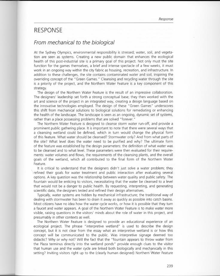
Response
RESPONSE
From mechanical to the biological
At the Sydney Olympics, environmental responsibility is stressed; water, soil, and vegetation are seen as systems. Creating a new public domain that enhances the ecologicalhealth of this post-industrial site is a primary goal of this project. Not only must the sitefunction for the games themselves, a brief and intense spectacle of a few weeks, it mustwork in an ongoing way within the city fabric as housing, recreation, and infrastructure. Inaddition to these challenges, the site contains contaminated water and soil, inspiring theoverriding concept of the "Green Games." Cleansing and recycling water through the siteis a priority of the project, and the Northern Water Feature is a key component of thisstrategy.
The design of the Northern Water Feature is the result of an impressive collaboration.The designers' leadership set forth a strong conceptual base; they then worked with theart and science of the project in an integrated way, creating a design language based onthe innovative technologies employed. The design of these "Green Games" underscoresthis shift from mechanical solutions to biological solutions for remediating or enhancingthe health of the landscape. The landscape is seen as an ongoing, dynamic set of systems,rather than a place possessing problems that are solved "forever."
The Northern Water Feature is designed to cleanse storm water run-off, and provide aprominent public gathering place. It is important to note that there were several ways thata cleansing wetland could be defined, which in turn would change the physical formof this feature. What water should be cleansed? Stormwater only? And from what parts ofthe site? What level does the water need to be purified and why? The ultimate formof the feature was established by the design parameters: the definition of what water wasto be cleansed and to what level. These parameters were then evaluated for their requirements: water volumes and flows, the requirements of the cleansing plants, and the overallgoals of the wetland, which all contributed to the final form of the Northern WaterFeature.
It is critical to understand that the designers didn't just solve a water problem; theyrefined their goals for water treatment and public interaction after evaluating severaloptions. A key question was the relationship between water quality and public safety. Thefountain would be enticing to visitors, necessitating that the water be cleansed to a levelthat would not be a danger to public health. By requesting, interpreting, and generatingscientific data, the designers tested and refined their design alternatives.
Typically, water systems are hidden by mechanical infrastructure; the traditional way ofdealing with stormwater has been to drain it away as quickly as possible into catch basins.Most citizens have no idea how the water cycle works, or how it is possible that they turna faucet and water appears. A goal of the Northern Water Feature is to make water morevisible, raising questions in the visitors' minds about the role of water in this project, andpresumably in other contexts as well.
The Northern Water Feature is designed to provide an educational experience of anecological project. The phrase "interpretive wetland" is used to describe the designconcept, but it is not clear from the essay what an interpretive wetland is or how thisconcept will be communicated to the public. Was interpretive signage deemed toodidactic? Why or why not? Will the fact that the "fountain appears to throw water fromthe Plaza terminus directly into the wetland ponds" provide enough clues to the visitorthat human use and the water cycle are linked both biologically and mechanically in thissetting? Inviting visitors right up to the (clearly human designed) Northern Water Feature
239
Sydney Olympics 2000
will provide the opportunity to experience wetlands as part of an urban, public environment, where they can then be seen not just as a piece of "nature" that one sees in the"country," but as a part of city life, and a new kind of "green infrastructure."
In ecological design, problems can be simply revealed to the public or they can beaddressed. At the Sydney Olympics, site problems are being addressed and in additionthere is interest in this remediation being revealed to the visitor. The Northern WaterFeature is designed to be seen as a landscape of remediation, while highlighting thebeauty of the natural processes of water movement and plant growth. A powerful addition to the project would be an experimental component, for example, testing one type ofplant over another for its cleansing properties. This is the next step that an ecologicaldesign project could take.
A precedent for this increased level of collaboration between art and science is theproject" Revival Field." Created in 1990, this seminal project was a collaboration betweenartist Mel Chin and scientist Rufus Chaney of the United States Department of Agriculture.Chaney's pioneering research indicated that some plants had the ability to cleanse soil byprocessing contaminants through their vascular system. Laboratory research was broughtto the field when Chin and Chaney planted a test plot on contaminated land near St Paul,Minnesota. Chin utilized the quartered circle for the form of the garden, an ancient formrecalling medieval herb gardens. "Revival Field" provides a model for collaborationbetween designers and scientists; scientists would benefit by working with more designedlandscapes, especially in urban areas, and designers could expand their own knowledgebase of remediation technologies as well as contributing to ongoing research.
As seen at Sydney, innovative remediation technologies have implications for a new language of built form in the landscape. The example of the Northern Water Feature showsus that cleansing wetlands - constructed systems that utilize plants to remove toxins fromwater - can also be urban public space. This is a new and potent type of hybrid landscape,a new type of manufactured site.
240
Part IV
Postscript
"Dialogues with the Contributors" expands on the research and project work highlightedin the essays in Parts II and III.
Three panel discussions took place on April 4, 1998 during the Manufactured Sites Conference at the Harvard Graduate School of Design. The audience comprised regulators anddesign and engineering practitioners from the public and private sectors as well as academics and students from design schools across the country. The discussions were led by amoderator and the panel's questions and comments were recorded, transcribed andappear here in an edited form.
The discussions focused on further and more detailed questions arising from the conference presentations, including clarification of new and innovative technical procedures andenvironmental construction materials, and discussion of interdisciplinary research anddesign collaboration. The three moderators were Deborah Marton, City of New York Parksand Recreation Department, a practicing landscape architect and lawyer; George Hargreaves, Chairman of the Department of Landscape Architecture, Harvard GraduateSchool of Design; and Daniel Winterbottom, Assistant Professor of Landscape Architecture
. at the University of Washington, Seattle. Participating contributors are identified at thebeginning of each panel.

Chapter 17
Dialogues with the contributorsNiall Kirkwood
Panel discussion 1
The participants are identified as follows:Deborah Marton, Landscape Architect, City of New York Natural Resources Group
(Moderator).Wendi Goldsmith, Bioengineer, The Bioengineering Group, Inc.Lucinda Jackson, Staff Environmental Scientist, Chevron Corporation.Kirt Rieder, Landscape Architect, Hargreaves Associates.Steve Rock, Environmental Engineer, US.EPA.William Young, Landscape Architect, The Dawson Corporation.
243
Figure 17. 1 Panel 1participants, from left toright, Wendi Goldsmith,Steve Rock, and LucindaJackson
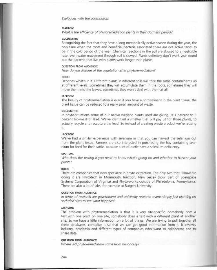
Dialogues with the contributors
MARTON:
What is the efficiency of phytoremediation plants in their dormant period?
GOLDSMITH:
Recognizing the fact that they have a long metabolically active season during the year, theonly time when the roots and beneficial bacteria associated there are not active tends tobe in the cold period of the year. Chemical reactions in the soil are slowed to a negligiblerate; even water movement through soil is slowed. Plants definitely don't work year roundbut the bacteria that live with plants work longer than plants.
QUESTION FROM AUDIENCE:
How do you dispose of the vegetation after phytoremediation?
ROCK:
Depends what's in it. Different plants in different soils will take the same contaminants upat different levels. Sometimes they will accumulate them in the roots, sometimes they willmove them into the leaves, sometimes they won't deal with them at all.
JACKSON:
The beauty of phytoremediation is even if you have a contaminant in the plant tissue, theplant tissue can be reduced to a really small amount of waste.
GOLDSMITH:
In phyto-situations some of our native wetland plants used are giving us 1 percent to 3percent bio-mass of lead. We've identified a smelter that will pay us for those plants, toactually recycle and recapture the lead. So instead of creating waste product we're reusingit.
JACKSON:
We've had a similar experience with selenium in that you can harvest the selenium outfrom the plant tissue. Farmers are also interested in purchasing the hay containing selenium for feed for their cattle, because a lot of cattle have a selenium deficiency.
MARTON:
Who does the testing if you need to know what's going on and whether to harvest yourplants?
ROCK:
There are companies that now specialize in phyto-extraction. The only two that I know aredoing it are Phytotech in Monmouth Junction, New Jersey (now part of EdenspaceSystems Corporation of Virginia) and Phyto-works outside of Philadelphia, Pennsylvania.There are also a lot of labs, for example at Rutgers University.
QUESTION FROM AUDIENCE:
In terms of research are government and university research teams simply just planting onsecluded sites to see what happens?
JACKSON:
The problem with phytoremediation is that it is very site-specific. Somebody does atest with one plant on one site, somebody does a test with a different plant at anothersite. So we have a little information on a lot of things. We are trying to pull together allthese databases, centralize it so that we can get good information from it. It involvesindustry, academia and different types of companies who want to collaborate and toshare data.
QUESTION FROM AUDIENCE:
Where did phytoremediation come from historically?
244
Panel discussion 1
ROCK:
If you search for phytoremediation, the earliest article with that word is around 1994 to1995. Older words such as bio-accumulation and geo-botany were used in the 1930s. Thefirst person to suggest using plants for remediation was Rufus Chaney at the US Department of Agriculture. He noticed that plants were taking up toxic levels of chemicals. Hethought: "we cannot use them for eating, perhaps though we can use that extractioncapacity for something else."
MARTON:
When should clean-up occur, what are the deadlines, and how do you dovetail the timingof phytoremediation with regulatory requirements?
ROCK:
By the time you get the money together to do a conventional clean-up, a phytoremediation installation will be complete, and will save you money in the process. Part of theanswer to why we are here is to discover how to integrate the remediation with landscapedesign. How to locate the appropriate plants, how to apply them to uptake the contaminants efficiently; so you use the site for a dual purpose - you're cleaning it up while you'reusing it.
JACKSON:
It takes time to convince the regulators, and sometimes you cannot and we have to do aconventional clean-up. We also can transform the site from a clean-up site to a researchsite and then they allow us to try an innovative technology.
GOLDSMITH:
When the government itself has financial responsibility for the cleaning activity it isremarkable how much more amenable they are talking about alternative, less-costly,better-integrated solutions with different time-frames.
MARTON:
Landscape architects are trained to look at the landscape as a pattern of patches and thegoal in some instances is to increase the flow of biotic elements among patches, increasing connectivity. Is the integration of geomorphology and design a way to address theconnectivity of a fragmented manufactured site?
YOUNG:
I believe that we have already over-inhabited the earth and there are far too many peopleto just think about restoration. In whatever I do, I look at whatever healing processes youcan do to complete the little patches that are left. We don't try and recreate nature, wejust put in something that will heal whatever the disturbance is.
GOLDSMITH:
I am a geomorphologist by training. Obviously some of the major issues that drive engineering design in phytoremediation projects involve things like the structure of surficialsediments, groundwater patterns and movement of groundwater. Landscape design froma stability standpoint, water movement and ultimately vegetation fit in there rather well. Avegetated slope can be stable at a much steeper angle than an unvegetated slope, forinstance. I think if we can understand geomorphology and how it can serve us as a designtool, we can for instance build vegetated slopes instead of structural slopes. These can bemore attractive, often less costly and typically far more beneficial biologically for all thereasons that you all have been reiterating.
MARTON:
One of the values that is brought to a site by landscape architects is that the future usersshould have some understanding of the site history and its former uses. That value may be
245
Dialogues with the contributors
somewhat at odds with the efficacy of remediation in the sense that it might not be in thebest interest in terms of restoration or cleansing the site to have a sign in the landscape ofthe site's prior use.
ROCK:
The unfortunately prevailing engineering attitude is that we'll get in there and make itsafe, and whatever else happens after that is somebody else's responsibility. Engineershave been long accused of focusing, which is the great strength and the great failing ofthe whole discipline. You put enough brainpower behind a problem and you are probablygoing to solve it.
RIEDER:
I took the time to talk to some of our engineering consultants for our Crissy Field projectand try and get a sense from them of the roles of the consultant over the course of thefour years of the process of the project. What did they see their role in restoration of thetidal marsh, did they feel that they were a part of it. It always came back to the word"restoration." I tried to get them to tell me what it means to restore. To a person theysaid, "we're there to solve a specific technical problem that you have put to us. Take therubble off the beach, make the channel function. "
GOLDSMITH:
I was asked to lead a panel discussion last week at the first conference of its type of theAmerican Society of Civil Engineers on the subject of how should engineers and ecologistswork together. Toward the end of the discussion it was clear that engineers and ecologistsare not the only consultants that need to be at the table. The other body that needed tobe represented is design and planning and that they probably need to lead and coordinatethe process. This came as a surprise to the people there. The engineers had not really seenthemselves as following directions.
Panel discussion 2
The participants are identified as follows:George Hargreaves, Landscape Architect (Moderator).Eric Carman, Environmental Engineer, ARCADIS Geharty & Miller.Michael Horne, Landscape Architect, GADD, Australia.Peter latz, Landscape Architect, Germany.Sue McNeil, Civil Engineer, University of Illinois, Chicago.
Dante Tedaldi, Environment~1 Engineer, Bechtel National Inc.
HARGREAVES:
I have a question for Dante [Tedaldi]. Looking at your two overlays, one with the precisemathematical model and one with the smoothing out. Tell me which works when you arepresenting this to the public?
TEDALDI:
The Potentially Responsible Party (PRP) refuted the results of the investigation, so therewas a lot of skepticism on the part of the public that the problem even existed. In thatsense, we had a little advantage in terms of smoothing out the results. What we neededto do was to sell the residents on the fact that there was a problem. Newer residents thathad moved in after the plant had closed were interested in the spots where their houseswere located. People come up to giant maps with street names and look for where exactlytheir houses were. That's tricky when they say, my house is here on the red spot and yourother map shows that that spot is clean. In the end we had to explain we were developinga feasibility study level estimate of the magnitude of the project. We costed out that 525
246
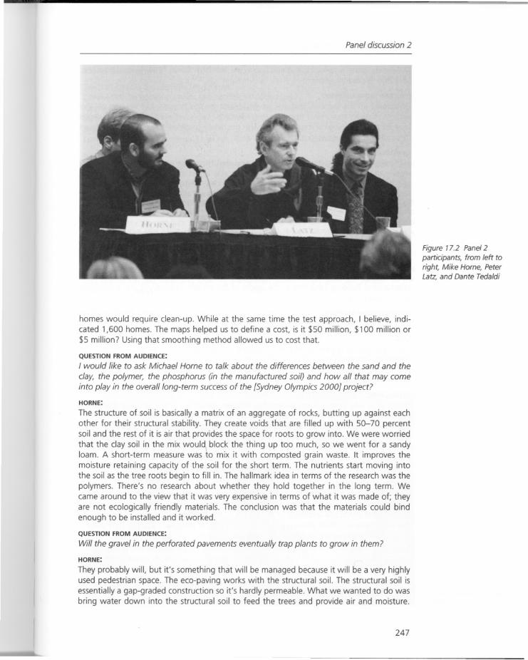
Panel discussion 2
homes would require clean-up. While at the same time the test approach, I believe, indicated 1,600 homes. The maps helped us to define a cost, is it $50 million, $100 million or$5 million? Using that smoothing method allowed us to cost that.
QUESTION FROM AUDIENCE:
I would like to ask Michael Horne to talk about the differences between the sand and the
clay, the polymer, the phosphorus (in the manufactured soil) and how all that may comeinto play in the overall long-term success of the [Sydney Olympics 2000} project?
HORNE:
The structure of soil is basically a matrix of an aggregate of rocks, butting up against eachother for their structural stability. They create voids that are filled up with 50-70 percentsoil and the rest of it is air that provides the space for roots to grow into. We were worried
that the clay soil in the mix woul~ block the thing up too much, so we went for a sandyloam. A short-term measure was to mix it with composted grain waste. It improves themoisture retaining capacity of the soil for the short term. The nutrients start moving intothe soil as the tree roots begin to fill in. The hallmark idea in terms of the research was thepolymers. There's no research about whether they hold together in the long term. Wecame around to the view that it was very expensive in terms of what it was made of; theyare not ecologically friendly materials. The conclusion was that the materials could bindenough to be installed and it worked.
QUESTION FROM AUDIENCE:
Will the gravel in the perforated pavements eventually trap plants to grow in them?
HORNE:
They probably will, but it's something that will be managed because it will be a very highlyused pedestrian space. The eco-paving works with the structural soil. The structural soil isessentially a gap-graded construction so it's hardly permeable. What we wanted to do wasbring water down into the structural soil to feed the trees and provide air and moisture.
247
Figure 17.2 Panel 2participants, from left toright, Mike Horne, PeterLatz, and Dante Tedaldi

Dialogues with the contributors
The excess water is collected and ends up in the Northern Water Feature, so it does leakback into the overall system.
QUESTION FROM AUDIENCE:
Continuing on the same subject, will we be able to see this process, can we connect thisprocess of water movement from the Great Terrace to the wetland? What I'm missing ishow do the technological issues interact with the media to define the spaces that take usthrough a series of experiences.
HARGREAVES:
In hindsight I think we should have understood that there was a way to express the harvesting of water and where it was going. I was very afraid of the system, the structuralsoil, the eco-paving, I still am. Now that I see it working, next time I will be more comfortable being expressive with it, making it part of the spatial and experiential quality of thedesign process.
QUESTION FROM AUDIENCE:
I was enormously intrigued by Mr Latz's project at Duisburg and I was wondering whatinspired him to take this very different approach? How did he decide about all the variousthings that would go on to the site - was it your client, or was it you?
LATZ:
It was very complicated - there were three agencies involved: the town, the state, and theInternational Building Exhibition as the leader of the project, but really it was a combination of science, art and tradition.
QUESTION FROM AUDIENCE:
Do you think there will be other projects that will be similar to it?
LATZ:
I am working on a new project like Duisburg but surrounded by mines. It presents aninteresting approach to what could be the beginnings of an international park just withinthe borders of three countries - France, Belgium, and Luxembourg - but I think it is reallyfar too complicated!
HARGREAVES:
The reason why Peter's [Latz] project has leftover industrial ruins is because that is theapproach that they have been doing in Europe for thousands of years, and it would costmore to remove the ruins than to leave them. In Europe there is more of a tendency totreat what society does as layer, upon layer, upon layer. Whereas here we erase things inorder to make them natural. What Peter did was to take it beyond that and introduce anew landscape, one that is above and beyond recent times. I think what Peter has takenon is a celebration of the site, it's a wholly different concept.
MEMBER OF AUDIENCE:
Peter's work is also in response to the materials that he is choosing. I think the differencemight be with your work [George Hargreaves] and some of the work that we see done bysome of the landscape architects in the United States is that the way that they look intothe new material. I think the way you find inspiration for the new work in a new place isthe material that you are looking at and using, is this true?
LATZ:
I think it was the materials. The possibility to make a metamorphosis. It was not just tomake it feel historical (concerning the industrial heritage associated with the site). It is ourheritage and we have to protect it - but that is not possible. In the first stage it is necessary to find out the new hue of these things: how can I use these objects?; then we havethe second stage: what is it possible to make in this place?
248
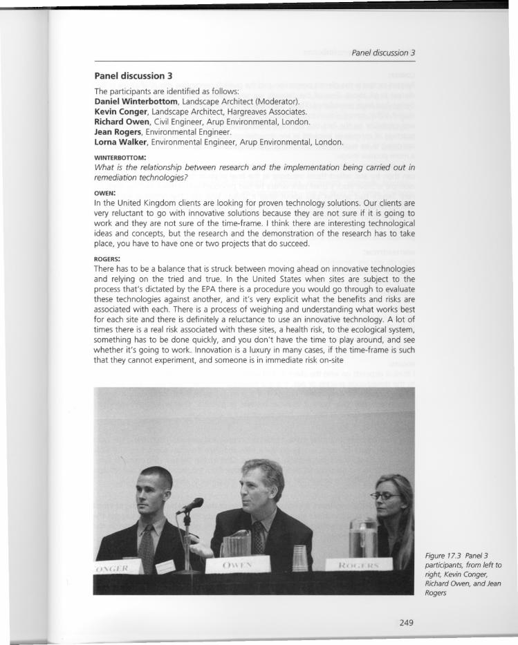
Panel discussion 3
Panel discussion 3
The participants are identified as follows:Daniel Winterbottom, Landscape Architect (Moderator).Kevin Conger, Landscape Architect, Hargreaves Associates.Richard Owen, Civil Engineer, Arup Environmental, London.Jean Rogers, Environmental Engineer.Lorna Walker, Environmental Engineer, Arup Environmental, London.
WINTERBonoM:
What is the relationship between research and the implementation being carried out inremediation technologies?
OWEN:
In the United Kingdom clients are looking for proven technology solutions. Our clients arevery reluctant to go with innovative solutions because they are not sure if it is going towork and they are not sure of the time-frame. I think there are interesting technologicalideas and concepts, but the research and the demonstration of the research has to takeplace, you have to have one or two projects that do succeed.
ROGERS:
There has to be a balance that is struck between moving ahead on innovative technologiesand relying on the tried and true. In the United States when sites are subject to theprocess that's dictated by the EPA there is a procedure you would go through to evaluatethese technologies against another, and it's very explicit what the benefits and risks areassociated with each. There is a process of weighing and understanding what works bestfor each site and there is definitely a reluctance to use an innovative technology. A lot oftimes there is a real risk associated with these sites, a health risk, to the ecological system,something has to be done quickly, and you don't have the time to play around, and seewhether it's going to work. Innovation is a luxury in many cases, if the time-frame is suchthat they cannot experiment, and someone is in immediate risk on-site
249
Figure 17.3 Panel 3participants, from left toright, Kevin Conger,Richard Owen, and Jean
Rogers
Dialogues with the contributors
CONGER:
Related to that is the client's perception and the public's perception about what site remediation is all about. Few of the projects we saw alluded to the fact that the final sitedesign had been remediated. There was no way to interpret that the site had been remediated. What comes closest to that are the sustainable companies that use it as marketingand capitalize on the fact that they are making this investment in positive environmentalpractices. If companies involved in site remediation were to take that attitude, where theyare going to be explicitly demonstrating that remediation in their final design, they will geta more positive image.
As designers we first look to the engineers to choose the functional solutions so that wecan then try and reflect those solutions in the final physical design. I think a really goodexample is Steve Rock's small park where he had proposed one scheme and the NationalPark Service had another idea about what it should look like. The potential for form making results from an interpretation of the site that reflects the engineering and remediation processes. What these forms are, designers never know, because they do not knowenough about remediation. We try to collaborate, bring people in that will show usperhaps the solution and that will make it evident in the final design.
WINTERBonoM:
How do you see remediation as establishing a new framework for land development, conservation, infrastructure, recreation, and is there going to be some form of transformationabout how people view these as opportunities? In the Salford Docks Project fish wereintroduced; could you introduce habitat?
WALKER:
We did have to do a lot just to bring food and oxygen back into the water to get the fishback. There was another quite apparently simple piece of work that was very difficult todo, which was to locate where vegetation could occur in terms of water depth. We didnot have all the research, a lot of it was initiation to see what you can do.
ROGERS:
I think it depends on who the client is, and whether they want to make it expressly relatedto the remediation process or not. If it is a municipal or government client they are morewilling to make a "monument" out of it. If it is an industrial client, particularly if it is anoperating facility, they want it to be as discrete as possible. They really don't want anymemory of the fact that they may have degraded the landscape.
CONGER:
They want to cover it up, and make it look picturesque and pastoral. That's the crime rightthere, they make so much money on these sites and then they just cover it up and walkaway. I don't think it's just enough to do that. One of the biggest constraints is time.There is I think the potential for design form to derive from the time-span of a remediationprocess or a landscape design that responds from one phase of clean-up to another./
OWEN:
In the multidisciplinary team, it's not only the timing of the project but the timing of whenyou bring on consultants into the team, for example landscape architects. So you get thebalance between something that the engineer is sure is going to work alongside thecorrect design expression.
CONGER:
The flip-side of the point is sometimes the landscape architect does not understand theprocesses and pays them lip service and makes something that looks like an engineerdesigned it, and maybe is not. The cooperation has to work the other way, because landscape architects do not have all the knowledge necessary.
250
Panel discussion 3
ROGERS:
That goes back to the education process, which is so important. I don't think it is reallybeing addressed in landscape programs, where people are understanding what kind ofsituations they may face on these contaminated sites, how they are typically remediated,what the suite of technologies is that apply, and how long it will take. They don't getinvolved early on in the remediation process when these are being discussed. Multidisciplinary teams are generally formed later, but they are not as effective as they could be. Thedesigners are not willing to get in and try to understand the science and work with thepossibilities.
WALKER:
The group that we work in, we have biologists, chemists, engineers, planners, environmental scientists and landscape architects and sociologists - we all sit in the same buildingand work together. I think that pushes the design process further because you havepeople to test things off - surely that is the way it has to be, particularly with thecomplexities of manufactured sites.
--
251

Figure credits
Cover image, Latz + Partner, image courtesy of Christa Panick; Chapter 1 figures, NiallKirkwood; Chapter 3 figures, Chevron Corporation; Chapter 4 figures, ARCADIS Geharty& Miller; Chapter 5 figures, Steve Rock; Figure 6.1, Sue McNeil; Figures 6.2, 6.3, 6.4, SueMcNeil, courtesy of Engineers Society of Western Pennsylvania; Chapter 7 figures, Bechtel;Chapter 8 figures, Arup Environmental; Figures 9.1, 9.2, 9.3, Jean Rogers; Figures 9.4,9.5, Jean Rogers, courtesy of Montgomery Watson; Figures 9.6, 9.7, 9.8, Jean Rogers,courtesy of Lance Larson; Figures 9.9, 9.10, 9.11, 9.12, 9.13, 9.14, 9.15, 9.16, JeanRogers; Figure 10.1, Deborah Marton, image courtesy of Robbin Bergors; Figure 10.2,Hargreaves Associates; Figures 10.3, 10.4, Latz + Partner; Figure 10.5, Hargreaves Associates; Figure 10.6, Brown & Rowe; Figure 10.7, Arup Environmental; Figures 10.8, 10.9,Martha Schwartz Inc.; Figures 10.10, 10.11, Mike Horne; Chapter 11 Figures 11.1, 11.2,11.5, 11.6, 11.8, 11.10, Michael Latz; Figures 11.4, 11.7, Latz + Partner; Figures 11.3,11.9, Christa Panick; Figures 12.1, 12.2, 12.3, The Bioengineering Group; Figures 12.4,12.5,12.6,12.7, Aviva Rahmani; Chapter 13 figures, William Young; Figures 14.1,14.2,14.3, Hargreaves Associates; Figure 14.4, Hargreaves Associates, courtesy of PresidioArchives; Figures 14.5,14.6,14.7,14.8,14.9, Hargreaves Associates; Figure 14.10, Hargreaves Associates, courtesy of Towill Inc.; Figures 14.11, 14.12, Hargreaves Associates;Figure 14.13, Hargreaves Associates, rendering courtesy of Chris Grubbs; Figure 14.14,Hargreaves Associates; Figure 14.15, Hargreaves Associates, rendering courtesy of ChrisGrubbs; Figures 14.16, 14.17, 14.18, Hargreaves Associates; Figure 14.19, HargeavesAssociates, rendering courtesy of Chris Grubbs; Figure 15.1, Mike Horne; Figure 15.2,Mike Horne, courtesy of Olympic Co-ordination Authority; Figures 15.3, 15.4, Mike Horne;Figure 15.5, Mike Horne, courtesy of Olympic Co-ordination Authority; Figure 15.6, MikeHorne; Figures 15.7, 15.8, Mike Horne, courtesy of Olympic Co-ordination Authority;Chapter 16 figures, Hargreaves Associates; Chapter 17 figures, Niall Kirkwood, imagescourtesy of Doug Cogger, Harvard Graduate School of Design.
252

Bibliography
A number of the essays are followed by notes, references and further reading lists relatedto the particular areas of focus. Please check at the conclusions of each of the followingchapters: 2 (Sattler), 4 (Carman), 6 (McNeil and Lange), 7 (Tedaldi), 9 (Rogers), 10 (Krinke),11 (Latz), 12 (Goldsmith), 14 (Rieder), and 15 (Horne).
Further reading
Barnett, Dianna and William Browning (1995) A Primer on Sustainable Building, Colo.: Rocky Moun-tain Institute.
Carney, T. (1998) Contaminated Land: Problems and Solutions, New York: E. & F.N. Spon.Craul, Philip (1999) Urban Soils: Applications and Practices, New York: John Wiley & Sons Inc.Crosbie, Michael J. (1995) Green Architecture, Rockport, Mass.: Rockport Publishers.
Mackenzie, Dorothy (1997) Green Design, London: Laurence King Publishing.Maughan, James (1993) Ecological Assessment of Hazardous Waste Sites, New York: Van Nostrand
Reinhold.
Pilatowicz, Grazyna (1995) Eco-Interiors, a Guide to Environmentally Conscious Interior Design, NewYork: John Wiley & Sons Inc.
Raskin, lIya and Burt D. Ensley (2000) Phytoremediation of Toxic Metals. Using Plants to Clean Up the
Environment, New York: John Wiley & Sons Inc.Saunders, William S. (ed.) (1998) School of Design. Richard Haag, Bloedel Reserve and Gas Works
Park, New York: Princeton Architectural Press.
Simons, Robert (1998) Turning Brownfields into Greenfields, Washington, DC: Urban Land Institute.US Green Building Council (1996) Sustainable Building Technical Manual, Denver: Public Technology,
Inc.
Westman, Walter (1985) Ecology, Impact Assessment and Environmental Planning, New York: JohnWiley & Sons, Inc.
Zeiher, Laura (1996) The Ecology of Architecture, New York: Whitney Library of Design, BPI Communications.
253
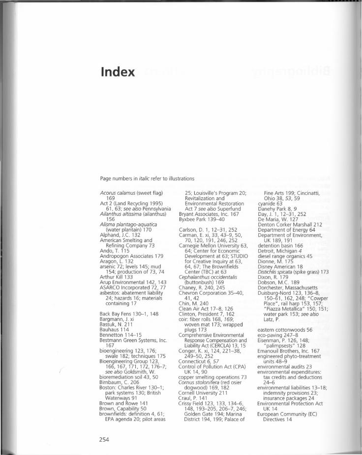
Index
Page numbers in italic refer to illustrations
Acarus calamus (sweet flag)169
Act 2 (Land Recycling 1995)61, 63; see also Pennsylvania
Ailanthus altissima (ailanthus)156
Alisma plantago-aquatica(water plantain) 170
Alphand, J.e. 132American Smelting and
Refining Company 73Ando, 1. 115Andropogon Associates 179Aragon, L. 132arsenic 72; levels 145; mud
154; production of 73, 74Arthur Kill 133Arup Environmental 142, 143ASARCO Incorporated 72, 77asbestos: abatement liability
24; hazards 16; materialscontaining 17
Back Bay Fens 130-1, 148Bargmann, 1. xiBassuk, N. 211Bauhaus 114Bennetton 114-15Bestmann Green Systems, Inc.
167bioengineering 123, 176;
swale 182; techniques 175Bioengineering Group 123,
166,167,171,172,176-7;see also Goldsmith, W.
bioremediation soil 43, 50Birnbaum, e. 206Boston: Charles River 130-1;
park systems 130; BritishWaterways 91
Brown and Rowe 141Brown, Capability 50brownfields: definition 4, 61;
EPA agenda 20; pilot areas
254
25; Louisville's Program 20;Revitalization andEnvironmental RestorationAct 7 see also Superfund
Bryant Associates, Inc. 167Byxbee Park 139--40
Carlson, D. 1, 12-31, 252Carman, E. xi, 33, 43-9, 50,
70,120,191,246,252Carnegie Mellon University 63,
64; Center for EconomicDevelopment at 63; STUDIOfor Creative Inquiry at 63,64, 67; The BrownfieldsCenter (TBC) at 63
Cephalanthus occidentalis(button bush) 169
Chaney, R. 240, 245Chevron Corporation 35--40,
41,42Chin, M. 240Clean Air Act 17-8, 126Clinton, President 7, 162coir: fiber rolls 168, 169;
woven mat 173; wrappedplugs 173
Comprehensive EnvironmentalResponse Compensation andLiability Act (CERCLA) 13, 15
Conger, K. xi, 124,221-38,249-50, 252
Connecticut 6, 57Control of Pollution Act (CPA)
UK 14, 90
copper smelting operations 73Comus stolonifera (red osierdogwood) 169, 182
Cornell University 211Craul, P. 141Crissy Field 123, 133, 134-6,
148, 193-205,206-7,246;Golden Gate 194; MarinaDistrict 194, 199; Palace of
Fine Arts 199; Cincinatti,Ohio 38, 53, 59
cyanide 63Danehy Park 8, 9Day, J. 1, 12-31, 252De Maria, W. 127Denton Corker Marshall 212Department of Energy 64Department of Environment,
UK 189,191detention basin 166Detroit, Michigan 4diesel range organics 45Dionne, M. 175
Disney American 18Distichlisspicata (spike grass) 173Dixon, R. 179Dobson, M.e. 189Dorchester, MassachusettsDuisburg-Nord 123, 136-8,
150-61,162,248; "CowperPlace", rail harp 153, 157;"Piazza Metallica" 150, 151;water park 153; see alsoLatz, P.
eastern cottonwoods 56eco-paving 247-8Eisenman, P. 126, 148;
"palimpsests" 128Emanouil Brothers, Inc. 167engineered phyto-treatment
units 48-9environmental audits 23environmental expenditures:
tax credits and deductions24-6
environmental liabilities 13-18;indemnity provisions 23;insurance packages 24
Environmental Protection ActUK14
European Community (EC)Directives 14
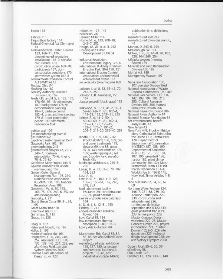
Exxon 133
Fabrica 115Fagus Shoe factory 114Federal Chemical Act (Germany)
14Federal Medical Center, Devens
123,166-71,176;bioengineered vegetativeinstallations 168-9; see alsocoir; closure 170;construction phase 169-70;participants 167; postconstruction conditions 170;stormwater system 167-8
Federal Water Pollution ControlAct (FWPCA) 13
Findlay, Ohio 54Flushing Bay 182Forestry Authority Research
Division (UK) 189Fresh Kills landfillS, 8, 123, 176,
178-90, 191-2; advantages187; background 178-9;demonstration planting184-7; garbage berms182--4; grass and tree seeding179-81; root penetrationpeport 190; salt marshrestoration 184
gabion wall 107gas manufacturing plant 6gas stations 62gasoline transfer terminal 35-7Gasworks Park 162, 164geomorphology 245geostatistical analysis 72, 75-7,
246-7; nonlinearinterpolation 75-6; Kriging75-6, 79-80
Geraldton Mine Project 143-5Glyceria canadensis (Canada
manna-grass) 169Golden Gate: General
Managment Plan 196, 210;National ParksAssociation(GGNPA) 134,196; NationalRecreation Area 196
Goldsmith, W. xi, 50, 123,166-75, 176, 243-6, 252 seealso Bioengineering
Grabosky, J. 211Grand Union Canal 89, 91,94,
95Great Miami River38greenfield sites x, 8Grimshaw, N. 115Group, Inc 123
Haag, R. 162Haley and Aldrich, Inc. 167Haller, S. 195Hanford nuclear site 164Hargreaves, G. xi, 246, 248,
252; associates 133, 134,135,139,145,221,222;seealso Crissy Field; see alsoSydney Olympics 2000
Harvard Graduate School ofDesign xi, xii, 123
Heizer, M. 127,145helixor 85, 86Herman Miller 114Horne, M. xi, 123,208-18,
246-7,252Hough, M. viii-ix, xi, 3, 252Housing and Urban
Development (HUD) 64
Industrial Revolution:environmental legacy 125-6
International Building ExhibitionEmscher Park (IBA) 150, 151
International Erosion ControlAssociation: environmentalachievement award 167
Iris versicolor (blue flag iris) 169
Jackson, L. xi, 8, 33, 35--42, 70,243-5,253
Johnson C.R. Associates, Inc.167
Juncus gerardii (black grass) 173
Kirkwood, N. 3-11, 41-2,50-1,59-60,69-71,81,102--4,119-21, 162, 243- 51, 253
Krinke, R. xi, 41-2,50-1,59-60,69-71,81,102--4,119-21, 123, 125--49,162-5,176-7,191-2,206-7,219-20,239--40,253
landfill 107, 139, 146,236;Brookfield (NY) 188, 189; capand cover treatments 179;closures 69; site 88; gases97-8, 143; tree roots on 178,189; waste tipping 90; seealso Stockley Park; see alsoFresh Kills
landscape architects x, 245-6,250
Lange, D. xi, 33, 61-8, 70,102,164,253
Latz, A xi,Latz, P.xi, 71, 103, 119, 123,
136-8,150-61,162,246,248,253
lead: abatement liabilityinsurance 24; concentrations72, 74; paint hazards 16
Leersia oryzoides (rice cutgrass)169
Li, D. xi, 1,8, 12-31,253Lindsay, P. 211Lobelia cardinalis (cardinal
flower) 169Love Canal 15, 164low temperature thermal
desorption (LnD) 197-8Lowry Arts Collection 88
Manchester Ship Canal 83, 84,86, 88; see also Salford Docks
Projectmanufactured sites: exhibition125,127,130; landscapeconference xi; locations 4;projects 133--48, postindustrial landscape 148-9;
Index
publication ix-x; definitions5-7
manufactured soils 247manufactured town gas plant 6,
44Marton,D.243-6,254McDonough,W.114McNeil, S. xi, 33, 61-8, 70,102,
120, 164, 246, 254Mimulus ringens (monkey
flower) 169Minerals and Land Reclamation
Division (UK) 189Moffat AJ. 189Montgomery Watson 197
Napa Pipe Corporation 106,107; see also Oregon Steel
National Association of WasteDisposal Contractors (UK) 189
National Park Service 133, 134,142,193,194,196,210,250; Cultural ResourceDivision 195, 206; NaturalResources Division 206
National Research Council 206National RiversAuthority 14National Science Foundation 64net environmental benefit
analysis 40,42New Jersey 43
New York 4-5; Brooklyn Bridgepiers; Cathedral of Saint Johnthe Divine 171; Central Park128; Department ofEnvironmental Conservation(NYSDEC) 187, 188, 190;Department of Sanitation(NYCDOS) 123, 179, 184,187, 190; greenbelt 188;harbor 182; plant climaxcommunity 184; Salt MarshRestoration Team 133; saltmarsh restoration 133--4;World's Fair (in 1939) 145;New York Times Articles 4-5,8
Nine Mile Run 62, 64, 65, 67,69
Northern Water Feature 124,146-7,221-38,239--40;Aquatic Center pool 228,230; construction andestablishment 236;continuous deflectiveseparation unit (CDS) 233;gross pollutant trap (GPT)233; lemna ponds 228;Master Concept Designworkshop 222-25; MasterConcept Design 226, projectintroduction 221; "PublicDomain" 222-5, 229; sitedescription 225; technicaldesign development 228; seealso Sydney Olympics 2000
Ogden, Utah 35-6, 55,56oil refinery 38Olin, Laurie 128Olmsted, F.L. 128, 130-1, 148
255
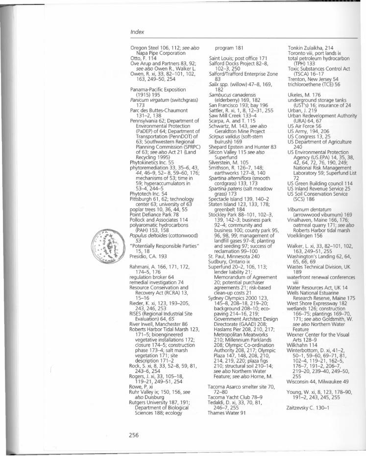
Index
Oregon Steel 106, 112; see alsoNapa Pipe Corporation
Otto, F. 114Ove Arup and Partners 83, 92;
see also Owen R., Walker L.Owen, R. xi, 33, 82-101,102,
163,249-50,254
Panama-Pacific Exposition(1915) 195
Panicum virgatum (switchgrass)173
Parc des Buttes-Chaumont131-2,138
Pennsylvania 62; Department ofEnvironmental Protection(PaDEP)of 64; Department ofTransportation (PennDOn of63; Southwestern RegionalPlanning Commission (SPRPC)of 63; see also Act 21 (LandRecycling 1995)
Phytokinetics Inc. 55phytoremediation 33, 35-6, 43,
44, 46-9, 52- 8, 59-60, 176;mechanisms of 53; time in59; hyperaccumulators in53-4, 244-5
Phytotech Inc. 54Pittsburgh 61, 62; technology
center 63; university of 63poplar trees 10, 36,44, 55Point Defiance Park 78Pollock and Associates 114
polyaromatic hydrocarbons(PAH) 153, 158Populus deltoides (cottonwood)
53
•.Potentially Responsible Parties"15,18
Presidio, CA. 193
Rahmani, A. 166, 171, 172,174-5,176
regulation broker 64remedial investigation 74Resource Conservation and
Recovery Act (RCRA) 13,15-16
Rieder, K. xi, 123, 193-205,243,246,253
RISES(Regional Industrial SiteEvaluation) 64, 65
River Irwell, Manchester 86Roberts Harbor Tidal Marsh 123,
171-5; bioengineeredvegetative installations 172;closu re 174-5; constructionphase 173-4; salt marshvegetation 171; sitedescription 171-2
Rock, S. xi, 8, 33, 52-8, 59, 81,243-6, 254
Rogers, J. xi, 33,105-18,119-21,249-51,254
Rowe, P. xiRuhr Valley ix; 150, 156, see
also DuisburgRutgers University 187, 191;
Department of BiologicalSciences 188; ecology
256
program 181
SaintLouis; post office 171Salford Docks Project 82-8,
102-3,250SalfordfTrafford Enterprise Zone
83salix spp. (willow) 47-8, 169,
182sambucus canadensis
(elderberry) 169, 182San Francisco 193; bay 196Sattler, R. xi, 1,8, 12-31,255Saw Mill Creek 133-4Scarpa, A. and 1. 115Schwartz, M. 143, see also
Geraldton Mine ProjectScirpus validus (soft -stem
bulrush) 169Shepard Epstein and Hunter 83Silicon Valley 115 see also
SuperfundSilverstein, M. 105Smithson, R. 126-7, 148;
earthworks 127-8, 140Spartina alterniflora (smooth
cordgrass) 133, 173Spartina patens (salt meadow
grass) 173Spectacle Island 139, 140-2Staten Island 123, 133, 178;
greenbelt 184Stockley Park 88-101, 102-3,
139, 142-3; business park92-4; community andbusiness 100; county park 95,96, 98, 99; management oflandfill gases 97-8; plantingand seeding 97; success ofreclamation 99-100
St. Paul, Minnesota 240Sudbury, Ontario ixSuperfund 20-2, 106, 113;
lender liability 21;Memorandum of Agreement20; potential purchaseragreements 21 ; risk-basedclean-up costs 21
Sydney Olympics 2000 123,145-8,208-18,219-20;background 208-10; ecopaving 214-16,219;Government Architect DesignDirectorate (GAAD) 208;Haslams Pier 208, 210, 217;Metropolitan Meatworks210; Millennium Parklands208; Olympic Co-ordinationAuthority 208, 217; OlympicPlaza 147, 148,208,210,214,219,220; plaza figs210; structural soil 210-14;see also Northern WaterFeature; see also Horne, M.
Tacoma Asarco smelter site 70,72-80
Tacoma Yacht Club 78-9Tedaldi, D. xi, 33, 70, 81,
246-7, 255Thames Water 91
Tonkin Zulaikha, 214Toronto viii, port lands ixtotal petroleum hydrocarbon
(TPH) 133Toxic Substances Control Act
(TSCA) 16-17Trenton, New Jersey 54trichloroethene (TCE) 56
Ukeles, M. 176underground storage tanks
(UST's) 16; insurance of 24Urban, 1. 219Urban Redevelopment Authority
(URA) 64,67US Air Force 56US Army, 194, 206US Congress 13, 25US Department of Agriculture
240US Environmental Protection
Agency (US.EPA)14, 35, 38,42,64,72,76,190,249;National Risk ManagementLaboratory 59; Superfund List72
US Green Building council 114US Inland Revenue Service25US Soil Conservation Service
(SCS) 186
Viburnum den tatum(arrowwood viburnum) 169
Vinalhaven, Maine 166, 176;oatmeal quarry 171; see alsoRoberts Harbor tidal marsh
Voelklingen 156
Walker, L. xi, 33, 82-101, 102,163,249-51,255
Washington's Landing 62, 64,65,66,69
Wastes Technical Division, UK189
waterfront renewal conferencesVIti
Water ResourcesAct, UK 14Wells National Estuarine
Research Reserve,Maine 175West Shore Expressway 182wetlands 126; construction
166-75; plantings 169-70,171; see also Goldsmith, W.see also Northern WaterFeature
Wexner Center for the VisualArts 128-9
Wilkhahn 114Winterbottom, D. xi, 41-2,
50-1,59-60,69-71,81,102-4, 119-21, 162-5,176-7, 191-2,206-7,219-20,239-40,249-50,255
Wisconsin 44, Milwaukee 49
Young, W. xi, 8, 123, 178-90,191-2,243,245,255
Zaitzevsky C. 130-1