manual t01-can - stw technic€¦ · manual t01-can temperature transmitter ... 5.5 configuration...
TRANSCRIPT
Temperature Transmitter T01-CAN
with CANopen Interface
62675
- Einwegpause -
Created: 02.08.2012 Revision date: Approved: Page 1 von 27 A. Krug 04.03.2015 Ma. Schreiber
Sensor-Technik Wiedemann GmbH, Am Baerenwald 6, 87600 Kaufbeuren, Tel.: +49(0)8341/95050, Fax: +49(0)8341/950555, www.sensor-technik.de
Manual
T01-CAN
Temperature Transmitter
with
CANopen Interface
Temperature Transmitter T01-CAN
with CANopen Interface
62675
- Einwegpause -
Created: 02.08.2012, A. Krug Revision date: 04.03.2015 Ma. Schreiber Page 2 von 27
Sensor-Technik Wiedemann GmbH, Am Baerenwald 6, 87600 Kaufbeuren, Tel.: +49(0)8341/95050, Fax: +49(0)8341/950555, www.sensor-technik.de
Table of Contents
1 History ............................................................................................................................................3 2 General ...........................................................................................................................................4 3 CAN Interface .................................................................................................................................4 4 T01-CAN Specification ...................................................................................................................4
4.1 Supply Voltage +US ...................................................................................................................4 4.2 CAN Interface ............................................................................................................................4 4.3 Environment ..............................................................................................................................5 4.4 Connector Pin Assignment (CiA DR303-1) ...............................................................................5
5 CANopen communication ...............................................................................................................5 5.1 Summary of the CANopen functions .........................................................................................5 5.2 Object Dictionary: Communication Profile .................................................................................6 5.3 Object Dictionary: Manufacturer Specific Profile .......................................................................8 5.4 Object Dictionary: Device Profile ...............................................................................................9 5.5 Configuration of the transmit PDO ..........................................................................................11 5.6 Emergency Message ...............................................................................................................13
6 Layer setting services ...................................................................................................................14 6.1 Supported services ..................................................................................................................15 6.2 LSS example ...........................................................................................................................19
7 CAN Communication without CANopen Functionality ..................................................................20 7.1 Basic Configuration .................................................................................................................20 7.2 Network Operation without CANopen Master .........................................................................20
7.2.1 SDO abort codes ..........................................................................................................22 7.3 Cyclically Sending ...................................................................................................................22 7.4 Change Node Configuration Manually.....................................................................................23 7.5 Reserved CAN Identifiers ........................................................................................................25
8 Extensions ....................................................................................................................................26 9 Appendix .......................................................................................................................................26
9.1 Definition of IEEE 32Bit (single precision) floating point numbers (IEEE-754 standard) ........26 9.2 CoEdit ......................................................................................................................................27 9.3 References ..............................................................................................................................27 9.4 Glossar ....................................................................................................................................27
Temperature Transmitter T01-CAN
with CANopen Interface
62675
- Einwegpause -
Created: 02.08.2012, A. Krug Revision date: 04.03.2015 Ma. Schreiber Page 3 von 27
Sensor-Technik Wiedemann GmbH, Am Baerenwald 6, 87600 Kaufbeuren, Tel.: +49(0)8341/95050, Fax: +49(0)8341/950555, www.sensor-technik.de
1 History
Version Date Name Change
1.00r0 02.08.12 A. Krug Document created
1.00r1 28.05.13 MB Text formatting improved
1.01r0 02.12.13 MB Object entry 0x4e00 for external serial number added
1.01r1 04.03.15 Ma. Schreiber Minor cosmetic changes for first release
Temperature Transmitter T01-CAN
with CANopen Interface
62675
- Einwegpause -
Created: 02.08.2012, A. Krug Revision date: 04.03.2015 Ma. Schreiber Page 4 von 27
Sensor-Technik Wiedemann GmbH, Am Baerenwald 6, 87600 Kaufbeuren, Tel.: +49(0)8341/95050, Fax: +49(0)8341/950555, www.sensor-technik.de
2 General
The temperature transmitter T01-CAN measures the physical quantity temperature. The range is -40…150°C for the medium. The measured value is transmitted on the CAN-Bus with the CANopen protocol. The transmitter takes about 107 samples per second, does filtering and converts the raw value into the output format.
The CAN2.0B interface is able to run up to a speed of 1 Mbit/sec.
The CAN protocol complies with the CANopen specification DS301, the temperature transmitter function is presented by the CANopen device profile DS404. Possible configurations are set by the object dictionary. Heartbeat and emergency messages guarantee high reliability.
With the “Layer setting services” (LSS, DSP305 V2.0), the desired bit rate and node-Id can be set easily.
3 CAN Interface
The device includes a Full CAN controller specified to CAN 2.0B. The physical layer of the 2-wire interface is specified according to ISO 11898. The wires are protected against short-circuit. By adjusting the rise times and fall times of the CAN signals, the noise emission is minimized to meet the EMC requirements. The bus termination resistor is not included in the device.
4 T01-CAN Specification
4.1 Supply Voltage +US
Supply voltage: 9…36 VDC, protected against reverse polarity
Current consumption at US = 24 VDC: I < 50 mA typical, IMAX < 100 mA
4.2 CAN Interface
Physical layer: 2-wire interface, 5 V level according to ISO 11898
Protected against short-circuit
max. Bit rate: 1 Mbit/sec
Signal rise time: Bit rate < 125 Kbit/sec 12 V/µsec (without bus)
Bit rate 125 Kbit/sec >24 V/µsec (without bus)
Bus termination: External
Protocol: CANopen DS301, Device Profile DS404
Temperature Transmitter T01-CAN
with CANopen Interface
62675
- Einwegpause -
Created: 02.08.2012, A. Krug Revision date: 04.03.2015 Ma. Schreiber Page 5 von 27
Sensor-Technik Wiedemann GmbH, Am Baerenwald 6, 87600 Kaufbeuren, Tel.: +49(0)8341/95050, Fax: +49(0)8341/950555, www.sensor-technik.de
4.3 Environment
EMC: Noise emission according to EN 50 081-2 noise immunity according to EN 50 082-2
Operating temperature: -40…+125°C Media temperature: -40…+150°C
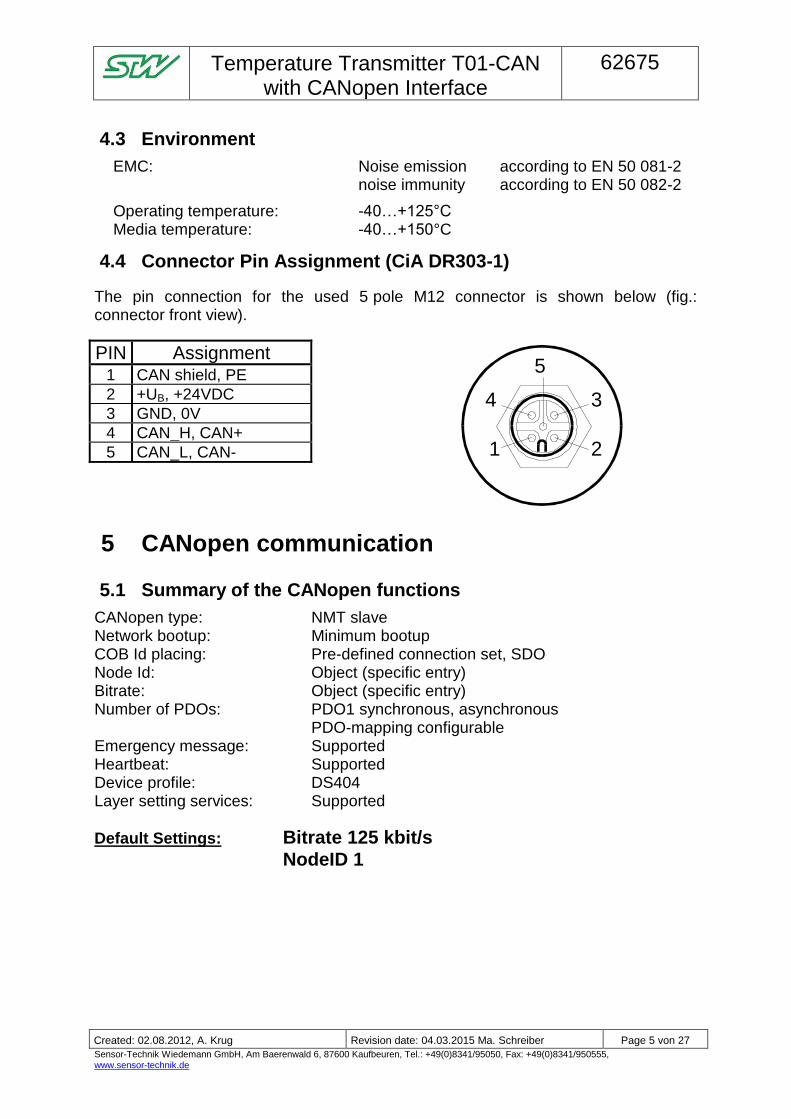
4.4 Connector Pin Assignment (CiA DR303-1)
The pin connection for the used 5 pole M12 connector is shown below (fig.: connector front view).
PIN Assignment 1 CAN shield, PE
2 +UB, +24VDC
3 GND, 0V
4 CAN_H, CAN+
5 CAN_L, CAN-
5 CANopen communication
5.1 Summary of the CANopen functions
CANopen type: NMT slave Network bootup: Minimum bootup COB Id placing: Pre-defined connection set, SDO Node Id: Object (specific entry) Bitrate: Object (specific entry) Number of PDOs: PDO1 synchronous, asynchronous PDO-mapping configurable Emergency message: Supported Heartbeat: Supported Device profile: DS404 Layer setting services: Supported
Default Settings: Bitrate 125 kbit/s
NodeID 1
1 2
34
5
Temperature Transmitter T01-CAN
with CANopen Interface
62675
- Einwegpause -
Created: 02.08.2012, A. Krug Revision date: 04.03.2015 Ma. Schreiber Page 6 von 27
Sensor-Technik Wiedemann GmbH, Am Baerenwald 6, 87600 Kaufbeuren, Tel.: +49(0)8341/95050, Fax: +49(0)8341/950555, www.sensor-technik.de
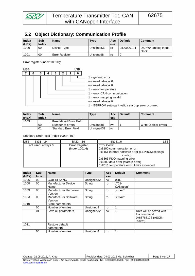
5.2 Object Dictionary: Communication Profile
Index
(HEX)
Sub
Index
Name Type Acc
ess
Default Comment
1000 00 Device Type Unsigned32 ro 0x00020194 DSP404 analog input block
1001 00 Error Register Unsigned8 ro 0
Error register (Index 1001H):
MSB LSB
7 6 5 4 3 2 1 0
1 = generic error
not used, always 0
not used, always 0
1 = error temperature
1 = error CAN communication
1 = error mapping invalid
not used, always 0
1 = EEPROM settings invalid / start up error occurred
Index
(HEX)
Sub
Index
Name Type Acc
ess
Default Comment
1003 Pre-defined Error Field
00 Number of errors Unsigned8 rw 1 Write 0: clear errors
01 Standard Error Field Unsigned32 ro
Standard Error Field (Index 1003H, 01):
MSB Bit31…24 Bit23…16 Bit15…0 LSB
not used, always 0 Error Register (Index 1001H)
Error Code: 0x8100 communication error 0x6161 internal software error (EEPROM settings
invalid) 0x6363 PDO mapping error 0x6300 data error (startup error) 0xF011 temperature error, limits exceeded
Index
(HEX)
Sub
Index
Name Type Acc
ess
Default Comment
1005 00 COB-ID SYNC Unsigned32 rw 0x80
1008 00 Manufacturer Device Name
String ro „T01-CANopen“
1009 00 Manufacturer Hardware Version
String ro „x.xxrx“
100A 00 Manufacturer Software Version
String ro „x.xxrx“
1010 Store parameters
00 Number of entries Unsigned8 ro 1
01 Save all parameters Unsigned32 rw 1 Data will be saved with the command 0x65766173 (ASCII: „save“)
1011 Restore default parameters
00 Number of entries Unsigned8 ro 1
Temperature Transmitter T01-CAN
with CANopen Interface
62675
- Einwegpause -
Created: 02.08.2012, A. Krug Revision date: 04.03.2015 Ma. Schreiber Page 7 von 27
Sensor-Technik Wiedemann GmbH, Am Baerenwald 6, 87600 Kaufbeuren, Tel.: +49(0)8341/95050, Fax: +49(0)8341/950555, www.sensor-technik.de
Index
(HEX)
Sub
Index
Name Type Acc
ess
Default Comment
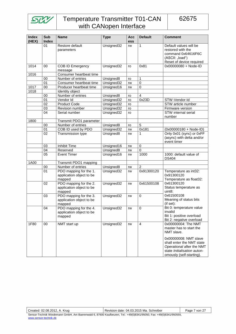
01 Restore default parameters
Unsigned32 rw 1 Default values will be restored with the command 0x64616F6C (ASCII: „load“) Reset of device required
1014 00 COB ID Emergency message
Unsigned32 ro 0x81 0x00000080 + Node-ID
1016 Consumer heartbeat time
00 Number of entries Unsigned8 ro 1
01 Consumer heartbeat time Unsigned32 rw 0
1017 00 Producer heartbeat time Unsigned16 rw 0
1018 Identity object
00 Number of entries Unsigned8 ro 4
01 Vendor Id Unsigned32 ro 0x23D STW-Vendor-Id
02 Product Code Unsigned32 ro STW article number
03 Revision number Unsigned32 ro Firmware version
04 Serial number Unsigned32 ro STW internal serial number
1800 Transmit PDO1 parameter
00 Number of entries Unsigned8 ro 5
01 COB ID used by PDO Unsigned32 rw 0x181 (0x00000180 + Node-ID)
02 Transmission type Unsigned8 rw 1 Only 0x01 (sync) or 0xFF (async) with delta and/or event timer
03 Inhibit Time Unsigned16 rw 0
04 Reserved Unsigned8 rw 0
05 Event Timer Unsigned16 rw 1000 1000: default value of DS404
1A00 Transmit PDO1 mapping
00 Number of entries Unsigned8 rw 2
01 PDO mapping for the 1. application object to be mapped
Unsigned32 rw 0x91300120 Temperature as int32: 0x91300120 Temperature as float32: 0x61300120 Status temperature as uint8: 0x61500108 Meaning of status bits (if set): Bit 0: temperature value invalid Bit 1: positive overload Bit 2: negative overload
02 PDO mapping for the 2. application object to be mapped
Unsigned32 rw 0x61500108
03 PDO mapping for the 3. application object to be mapped
Unsigned32 rw 0
04 PDO mapping for the 4. application object to be mapped
Unsigned32 rw 0
1F80 00 NMT start up Unsigned32 rw 4 0x00000004: The NMT master has to start the NMT slave.
0x00000008: NMT slave shall enter the NMT state Operational after the NMT state Initialisation auton-omously (self-starting).
Temperature Transmitter T01-CAN
with CANopen Interface
62675
- Einwegpause -
Created: 02.08.2012, A. Krug Revision date: 04.03.2015 Ma. Schreiber Page 8 von 27
Sensor-Technik Wiedemann GmbH, Am Baerenwald 6, 87600 Kaufbeuren, Tel.: +49(0)8341/95050, Fax: +49(0)8341/950555, www.sensor-technik.de
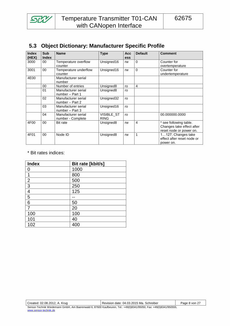
5.3 Object Dictionary: Manufacturer Specific Profile
Index
(HEX)
Sub
Index
Name Type Acc
ess
Default Comment
3000 00 Temperature overflow counter
Unsigned16 rw 0 Counter for overtemperature
3001 00 Temperature underflow counter
Unsigned16 rw 0 Counter for undertemperature
4E00 Manufacturer serial number
00 Number of entries Unsigned8 ro 4
01 Manufacturer serial number – Part 1
Unsigned8 ro
02 Manufacturer serial number – Part 2
Unsigned32 ro
03 Manufacturer serial number – Part 3
Unsigned16 ro
04 Manufacturer serial number - Complete
VISIBLE_STRING
ro 00.000000.0000
4F00 00 Bit rate Unsigned8 rw 4 * see following table. Changes take effect after reset node or power on.
4F01 00 Node ID Unsigned8 rw 1 1…127; Changes take effect after reset node or power on.
* Bit rates indices:
Index Bit rate [kbit/s]
0 1000
1 800
2 500
3 250
4 125
5 --
6 50
7 20
100 100
101 40
102 400
Temperature Transmitter T01-CAN
with CANopen Interface
62675
- Einwegpause -
Created: 02.08.2012, A. Krug Revision date: 04.03.2015 Ma. Schreiber Page 9 von 27
Sensor-Technik Wiedemann GmbH, Am Baerenwald 6, 87600 Kaufbeuren, Tel.: +49(0)8341/95050, Fax: +49(0)8341/950555, www.sensor-technik.de
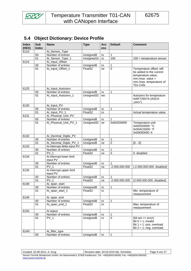
5.4 Object Dictionary: Device Profile
Index
(HEX)
Sub
Index
Name Type Acc
ess
Default Comment
6110 Ai_Sensor_Type
00 Number of entries Unsigned8 ro 1
01 Ai_Sensor_Type_1 Unsigned16 ro 100 100 = temperature sensor
6124 Ai_Input_Offset
00 Number of entries Unsigned8 ro 1
01 Ai_Input_Offset_1 Float32 rw 0 Temperature offset; will be added to the current temperature value; min./max. value = min./max. temperature of T01-CAN
6125 Ai_Input_Autozero
00 Number of entries Unsigned8 ro 1
01 Ai_Input_Autozero_1 Unsigned32 wo Autozero for temperature 0x6F72657A (ASCII: „zero“)
6130 Ai_Input_PV
00 Number of entries Unsigned8 ro 1
01 Ai_Input_PV_1 Float32 ro Actual temperature value
6131 Ai_Physical_Unit_PV
00 Number of entries Unsigned8 ro 1
01 Ai_Physical_Unit_PV_1 Unsigned32 rw 0x002D0000 Temperature unit: 0x002D0000: °C 0x00AC0000: °F 0x00050000: K
6132 Ai_Decimal_Digits_PV
00 Number of entries Unsigned8 ro 1
01 Ai_Decimal_Digits_PV_1 Unsigned8 rw 0 [0…5]
6133 Ai interrupt delta input PV
00 Number of entries Unsigned8 ro 1
01 PV_1 Float32 rw 0 0: disabled
6134 Ai interrupt lower limit input PV
00 Number of entries Unsigned8 ro 1
01 PV_1 Float32 rw -2.000.000.000 (-2.000.000.000: disabled)
6135 Ai interrupt upper limit input PV
00 Number of entries Unsigned8 ro 1
01 PV_1 Float32 rw -2.000.000.000 (2.000.000.000: disabled)
6148 Ai_span_start
00 Number of entries Unsigned8 ro 1
01 Ai_span_start_1 Float32 ro Min. temperature of measurement
6149 Ai_span_end
00 Number of entries Unsigned8 ro 1
01 Ai_span_end_1 Float32 ro Max. temperature of measurement
6150 Ai status
00 Number of entries Unsigned8 ro 1
01 PV_1 Unsigned8 ro 0 (bit set => error) Bit 0 = 1: invalid Bit 1 = 1: pos. overload Bit 2 = 1: neg. overload
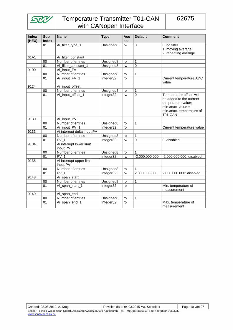
61A0 Ai_filter_type
00 Number of entries Unsigned8 ro 1
Temperature Transmitter T01-CAN
with CANopen Interface
62675
- Einwegpause -
Created: 02.08.2012, A. Krug Revision date: 04.03.2015 Ma. Schreiber Page 10 von 27
Sensor-Technik Wiedemann GmbH, Am Baerenwald 6, 87600 Kaufbeuren, Tel.: +49(0)8341/95050, Fax: +49(0)8341/950555, www.sensor-technik.de
Index
(HEX)
Sub
Index
Name Type Acc
ess
Default Comment
01 Ai_filter_type_1 Unsigned8 rw 0 0: no filter 1: moving average 2: repeating average
61A1 Ai_filter_constant
00 Number of entries Unsigned8 ro 1
01 Ai_filter_constant_1 Unsigned8 rw 0
9100 Ai_input_FV
00 Number of entries Unsigned8 ro 1
01 Ai_input_FV_1 Integer32 ro Current temperature ADC value
9124 Ai_input_offset
00 Number of entries Unsigned8 ro 1
01 Ai_input_offset_1 Integer32 rw 0 Temperature offset; will be added to the current temperature value; min./max. value = min./max. temperature of T01-CAN
9130 Ai_input_PV
00 Number of entries Unsigned8 ro 1
01 Ai_input_PV_1 Integer32 ro Current temperature value
9133 Ai interrupt delta input PV
00 Number of entries Unsigned8 ro 1
01 PV_1 Integer32 rw 0 0: disabled
9134 Ai interrupt lower limit input PV
00 Number of entries Unsigned8 ro 1
01 PV_1 Integer32 rw -2.000.000.000 -2.000.000.000: disabled
9135 Ai interrupt upper limit input PV
00 Number of entries Unsigned8 ro 1
01 PV_1 Integer32 rw 2.000.000.000 2.000.000.000: disabled
9148 Ai_span_start
00 Number of entries Unsigned8 ro 1
01 Ai_span_start_1 Integer32 ro Min. temperature of measurement
9149 Ai_span_end
00 Number of entries Unsigned8 ro 1
01 Ai_span_end_1 Integer32 ro Max. temperature of measurement
Temperature Transmitter T01-CAN
with CANopen Interface
62675
- Einwegpause -
Created: 02.08.2012, A. Krug Revision date: 04.03.2015 Ma. Schreiber Page 11 von 27
Sensor-Technik Wiedemann GmbH, Am Baerenwald 6, 87600 Kaufbeuren, Tel.: +49(0)8341/95050, Fax: +49(0)8341/950555, www.sensor-technik.de
5.5 Configuration of the transmit PDO
This chapter describes the configuration of the transmit PDO.
Dynamic mapping:
The PDO configuration is done by the OD entry TPDO1 mapping (index 0x1A00) and its sub-indices. The sub index 1 defines the first value (lower position) transmitted by the PDO. The sub index 2 defines the second value, the sub index 3 the third and the sub index 4 the fourth value transmitted by the PDO.
If not all values are used, the upper sub-indices must be set to 0.
To change the mapping, the following procedure must be applied:
1. Set the “Nr. of mapped objects” (0x1A00/0x00) to 0. => The PDO is deactivated.
2. Set the desired mapping values (0x1A00/0x01…0x04).
3. Set the “Nr. of mapped objects” (0x1A00/0x00) to the desired number of mapping objects.
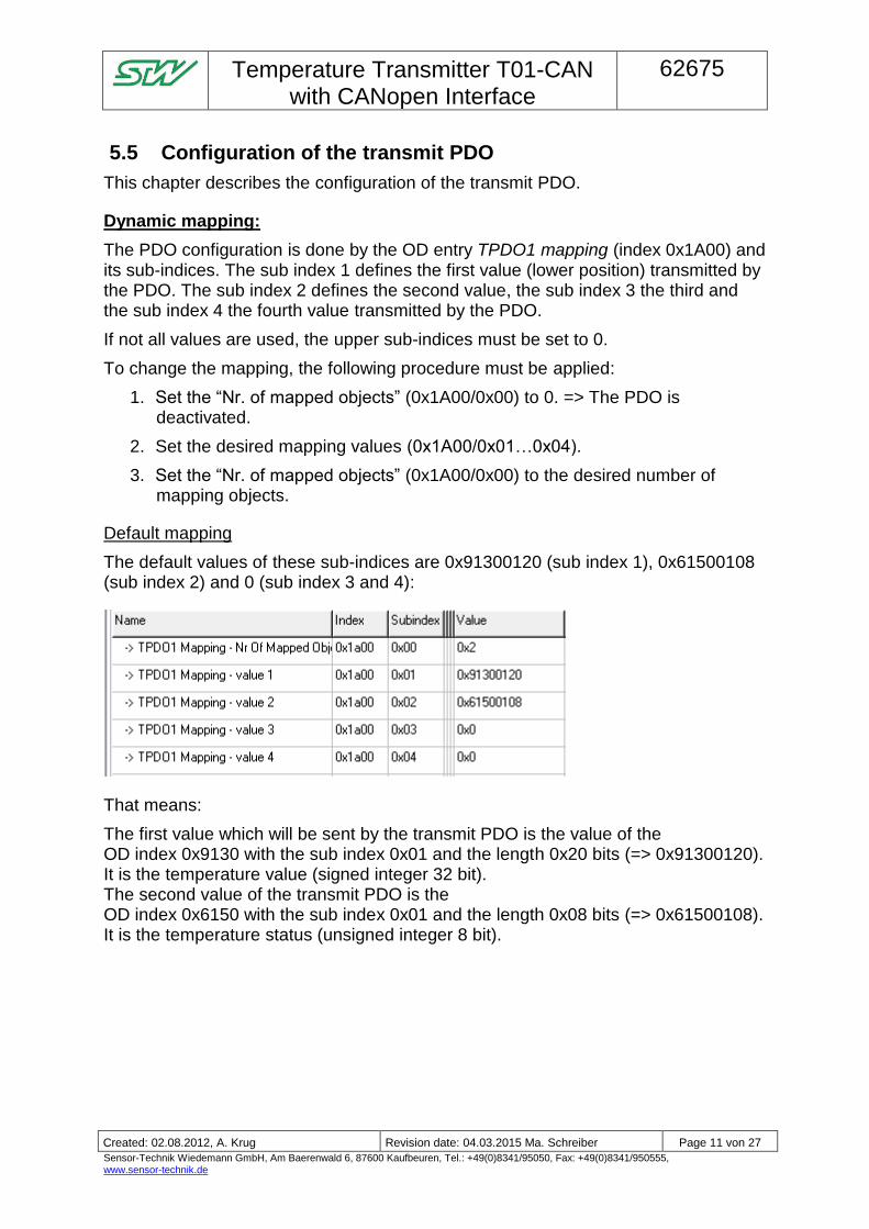
Default mapping
The default values of these sub-indices are 0x91300120 (sub index 1), 0x61500108 (sub index 2) and 0 (sub index 3 and 4):
That means:
The first value which will be sent by the transmit PDO is the value of the OD index 0x9130 with the sub index 0x01 and the length 0x20 bits (=> 0x91300120). It is the temperature value (signed integer 32 bit). The second value of the transmit PDO is the OD index 0x6150 with the sub index 0x01 and the length 0x08 bits (=> 0x61500108). It is the temperature status (unsigned integer 8 bit).
Temperature Transmitter T01-CAN
with CANopen Interface
62675
- Einwegpause -
Created: 02.08.2012, A. Krug Revision date: 04.03.2015 Ma. Schreiber Page 12 von 27
Sensor-Technik Wiedemann GmbH, Am Baerenwald 6, 87600 Kaufbeuren, Tel.: +49(0)8341/95050, Fax: +49(0)8341/950555, www.sensor-technik.de
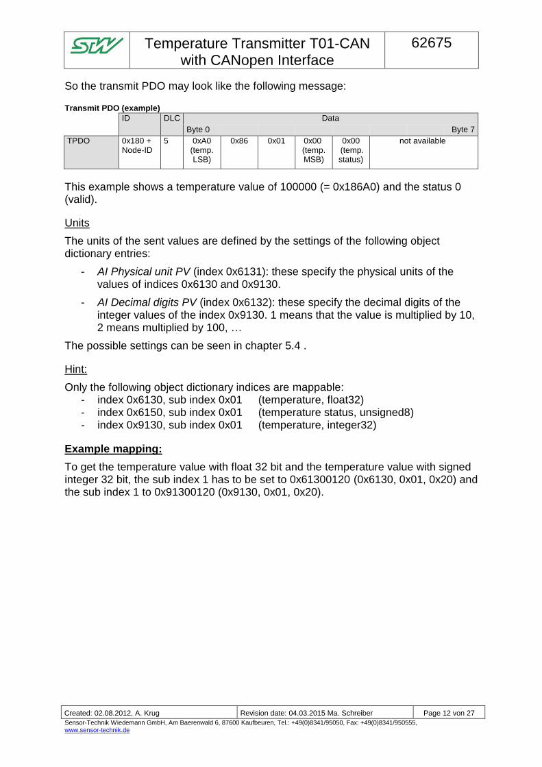
So the transmit PDO may look like the following message:
Transmit PDO (example)
ID DLC Data
Byte 0 Byte 7
TPDO 0x180 + Node-ID
5 0xA0 (temp. LSB)
0x86 0x01 0x00 (temp. MSB)
0x00 (temp. status)
not available
This example shows a temperature value of 100000 (= 0x186A0) and the status 0 (valid).
Units
The units of the sent values are defined by the settings of the following object dictionary entries:
- AI Physical unit PV (index 0x6131): these specify the physical units of the values of indices 0x6130 and 0x9130.
- AI Decimal digits PV (index 0x6132): these specify the decimal digits of the integer values of the index 0x9130. 1 means that the value is multiplied by 10, 2 means multiplied by 100, …
The possible settings can be seen in chapter 5.4 .
Hint:
Only the following object dictionary indices are mappable: - index 0x6130, sub index 0x01 (temperature, float32) - index 0x6150, sub index 0x01 (temperature status, unsigned8) - index 0x9130, sub index 0x01 (temperature, integer32)
Example mapping:
To get the temperature value with float 32 bit and the temperature value with signed integer 32 bit, the sub index 1 has to be set to 0x61300120 (0x6130, 0x01, 0x20) and the sub index 1 to 0x91300120 (0x9130, 0x01, 0x20).
Temperature Transmitter T01-CAN
with CANopen Interface
62675
- Einwegpause -
Created: 02.08.2012, A. Krug Revision date: 04.03.2015 Ma. Schreiber Page 13 von 27
Sensor-Technik Wiedemann GmbH, Am Baerenwald 6, 87600 Kaufbeuren, Tel.: +49(0)8341/95050, Fax: +49(0)8341/950555, www.sensor-technik.de
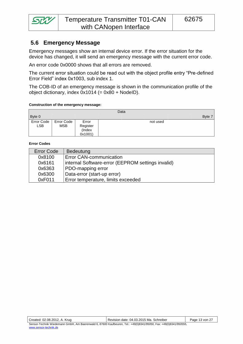
5.6 Emergency Message
Emergency messages show an internal device error. If the error situation for the device has changed, it will send an emergency message with the current error code.
An error code 0x0000 shows that all errors are removed.
The current error situation could be read out with the object profile entry “Pre-defined Error Field” index 0x1003, sub index 1.
The COB-ID of an emergency message is shown in the communication profile of the object dictionary, index 0x1014 (= 0x80 + NodeID).
Construction of the emergency message:
Data
Byte 0 Byte 7
Error Code LSB
Error Code MSB
Error Register (Index
0x1001)
not used
Error Codes
Error Code Bedeutung
0x8100 0x6161 0x6363 0x6300 0xF011
Error CAN-communication internal Software-error (EEPROM settings invalid) PDO-mapping error Data-error (start-up error) Error temperature, limits exceeded
Temperature Transmitter T01-CAN
with CANopen Interface
62675
- Einwegpause -
Created: 02.08.2012, A. Krug Revision date: 04.03.2015 Ma. Schreiber Page 14 von 27
Sensor-Technik Wiedemann GmbH, Am Baerenwald 6, 87600 Kaufbeuren, Tel.: +49(0)8341/95050, Fax: +49(0)8341/950555, www.sensor-technik.de
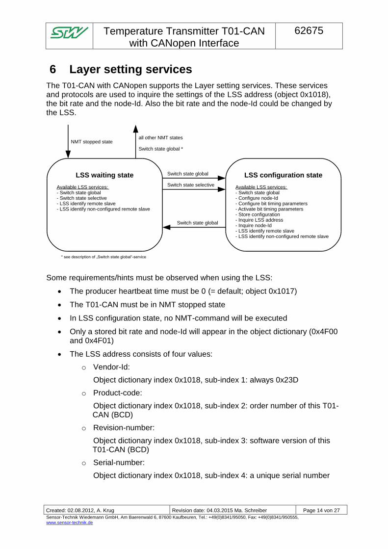
6 Layer setting services
The T01-CAN with CANopen supports the Layer setting services. These services and protocols are used to inquire the settings of the LSS address (object 0x1018), the bit rate and the node-Id. Also the bit rate and the node-Id could be changed by the LSS.
LSS waiting state
Available LSS services:- Switch state global- Switch state selective- LSS identify remote slave- LSS identify non-configured remote slave
NMT stopped stateall other NMT states
LSS configuration state
Available LSS services:- Switch state global- Configure node-Id- Configure bit timing parameters- Activate bit timing parameters- Store configuration- Inquire LSS address- Inquire node-Id- LSS identify remote slave- LSS identify non-configured remote slave
Switch state global
Switch state global
Switch state selective
Switch state global *
* see description of „Switch state global“-service
Some requirements/hints must be observed when using the LSS:
The producer heartbeat time must be 0 (= default; object 0x1017)
The T01-CAN must be in NMT stopped state
In LSS configuration state, no NMT-command will be executed
Only a stored bit rate and node-Id will appear in the object dictionary (0x4F00 and 0x4F01)
The LSS address consists of four values:
o Vendor-Id:
Object dictionary index 0x1018, sub-index 1: always 0x23D
o Product-code:
Object dictionary index 0x1018, sub-index 2: order number of this T01-CAN (BCD)
o Revision-number:
Object dictionary index 0x1018, sub-index 3: software version of this T01-CAN (BCD)
o Serial-number:
Object dictionary index 0x1018, sub-index 4: a unique serial number
Temperature Transmitter T01-CAN
with CANopen Interface
62675
- Einwegpause -
Created: 02.08.2012, A. Krug Revision date: 04.03.2015 Ma. Schreiber Page 15 von 27
Sensor-Technik Wiedemann GmbH, Am Baerenwald 6, 87600 Kaufbeuren, Tel.: +49(0)8341/95050, Fax: +49(0)8341/950555, www.sensor-technik.de
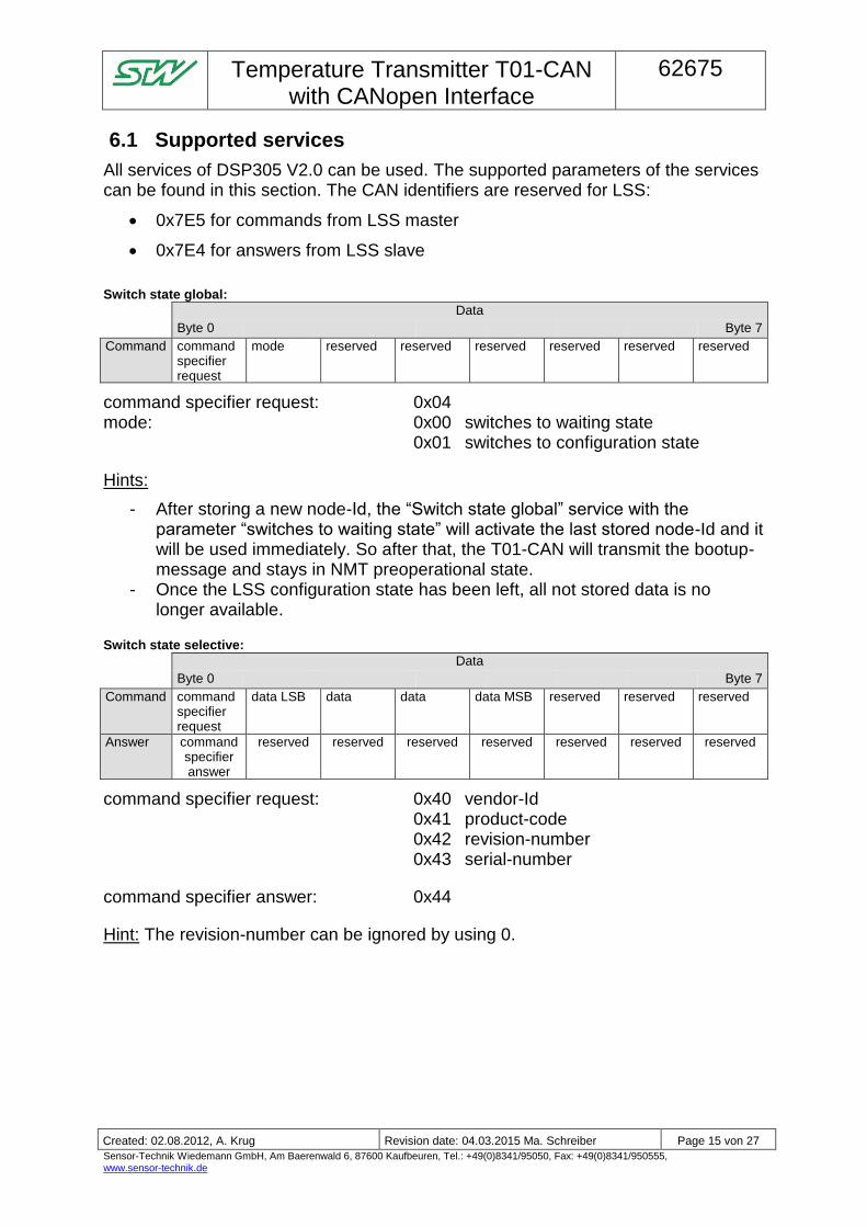
6.1 Supported services
All services of DSP305 V2.0 can be used. The supported parameters of the services can be found in this section. The CAN identifiers are reserved for LSS:
0x7E5 for commands from LSS master
0x7E4 for answers from LSS slave
Switch state global:
Data
Byte 0 Byte 7
Command command specifier request
mode reserved reserved reserved reserved reserved reserved
command specifier request: 0x04 mode: 0x00 switches to waiting state 0x01 switches to configuration state
Hints:
- After storing a new node-Id, the “Switch state global” service with the parameter “switches to waiting state” will activate the last stored node-Id and it will be used immediately. So after that, the T01-CAN will transmit the bootup-message and stays in NMT preoperational state.
- Once the LSS configuration state has been left, all not stored data is no longer available.
Switch state selective:
Data
Byte 0 Byte 7
Command command specifier request
data LSB data data data MSB reserved reserved reserved
Answer command specifier answer
reserved reserved reserved reserved reserved reserved reserved
command specifier request: 0x40 vendor-Id 0x41 product-code 0x42 revision-number 0x43 serial-number
command specifier answer: 0x44
Hint: The revision-number can be ignored by using 0.
Temperature Transmitter T01-CAN
with CANopen Interface
62675
- Einwegpause -
Created: 02.08.2012, A. Krug Revision date: 04.03.2015 Ma. Schreiber Page 16 von 27
Sensor-Technik Wiedemann GmbH, Am Baerenwald 6, 87600 Kaufbeuren, Tel.: +49(0)8341/95050, Fax: +49(0)8341/950555, www.sensor-technik.de
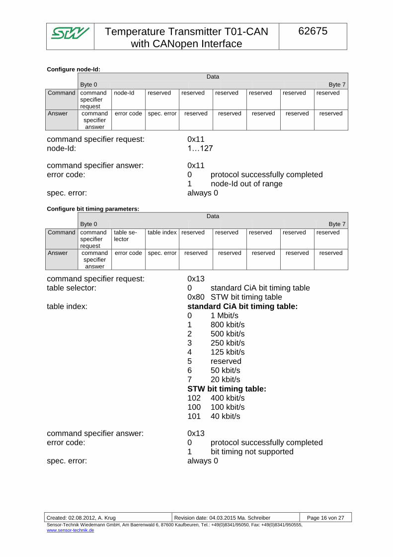
Configure node-Id:
Data
Byte 0 Byte 7
Command command specifier request
node-Id reserved reserved reserved reserved reserved reserved
Answer command specifier answer
error code spec. error reserved reserved reserved reserved reserved
command specifier request: 0x11 node-Id: 1…127
command specifier answer: 0x11 error code: 0 protocol successfully completed 1 node-Id out of range spec. error: always 0
Configure bit timing parameters:
Data
Byte 0 Byte 7
Command command specifier request
table se-lector
table index reserved reserved reserved reserved reserved
Answer command specifier answer
error code spec. error reserved reserved reserved reserved reserved
command specifier request: 0x13 table selector: 0 standard CiA bit timing table 0x80 STW bit timing table
table index: standard CiA bit timing table: 0 1 Mbit/s 1 800 kbit/s 2 500 kbit/s 3 250 kbit/s 4 125 kbit/s 5 reserved 6 50 kbit/s 7 20 kbit/s
STW bit timing table: 102 400 kbit/s
100 100 kbit/s 101 40 kbit/s
command specifier answer: 0x13 error code: 0 protocol successfully completed 1 bit timing not supported spec. error: always 0
Temperature Transmitter T01-CAN
with CANopen Interface
62675
- Einwegpause -
Created: 02.08.2012, A. Krug Revision date: 04.03.2015 Ma. Schreiber Page 17 von 27
Sensor-Technik Wiedemann GmbH, Am Baerenwald 6, 87600 Kaufbeuren, Tel.: +49(0)8341/95050, Fax: +49(0)8341/950555, www.sensor-technik.de
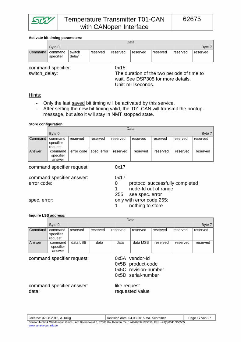
Activate bit timing parameters:
Data
Byte 0 Byte 7
Command command specifier
switch_ delay
reserved reserved reserved reserved reserved reserved
command specifier: 0x15 switch_delay: The duration of the two periods of time to
wait. See DSP305 for more details. Unit: milliseconds.
Hints:
- Only the last saved bit timing will be activated by this service. - After setting the new bit timing valid, the T01-CAN will transmit the bootup-
message, but also it will stay in NMT stopped state.
Store configuration:
Data
Byte 0 Byte 7
Command command specifier request
reserved reserved reserved reserved reserved reserved reserved
Answer command specifier answer
error code spec. error reserved reserved reserved reserved reserved
command specifier request: 0x17
command specifier answer: 0x17 error code: 0 protocol successfully completed 1 node-Id out of range
255 see spec. error spec. error: only with error code 255: 1 nothing to store
Inquire LSS address:
Data
Byte 0 Byte 7
Command command specifier request
reserved reserved reserved reserved reserved reserved reserved
Answer command specifier answer
data LSB data data data MSB reserved reserved reserved
command specifier request: 0x5A vendor-Id 0x5B product-code 0x5C revision-number 0x5D serial-number
command specifier answer: like request data: requested value
Temperature Transmitter T01-CAN
with CANopen Interface
62675
- Einwegpause -
Created: 02.08.2012, A. Krug Revision date: 04.03.2015 Ma. Schreiber Page 18 von 27
Sensor-Technik Wiedemann GmbH, Am Baerenwald 6, 87600 Kaufbeuren, Tel.: +49(0)8341/95050, Fax: +49(0)8341/950555, www.sensor-technik.de
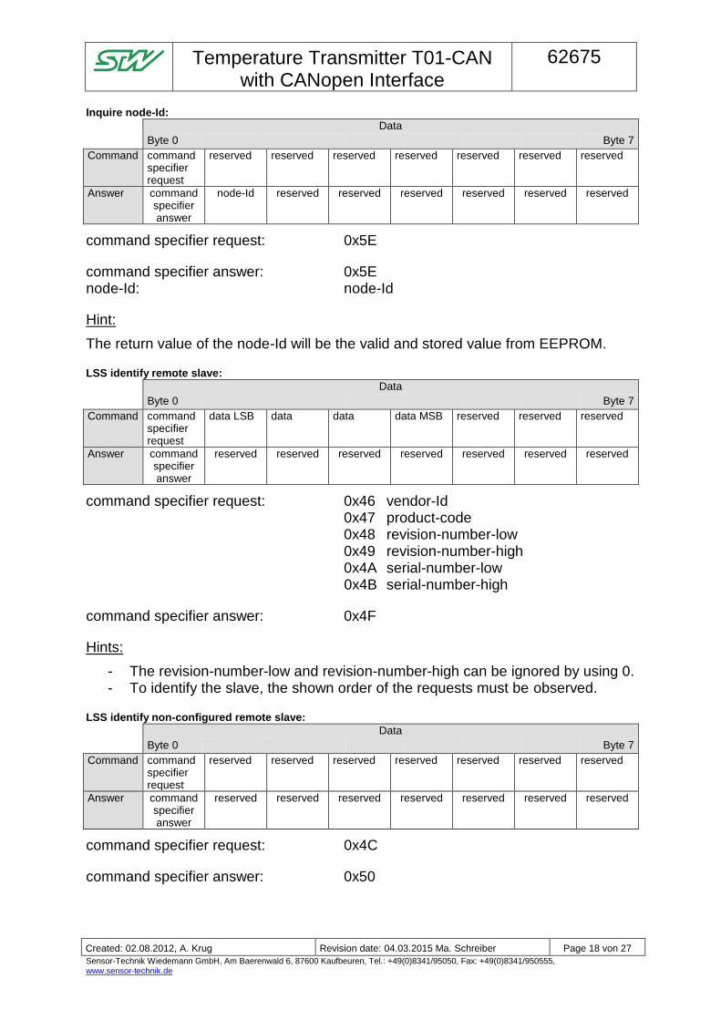
Inquire node-Id:
Data
Byte 0 Byte 7
Command command specifier request
reserved reserved reserved reserved reserved reserved reserved
Answer command specifier answer
node-Id reserved reserved reserved reserved reserved reserved
command specifier request: 0x5E
command specifier answer: 0x5E node-Id: node-Id
Hint:
The return value of the node-Id will be the valid and stored value from EEPROM.
LSS identify remote slave:
Data
Byte 0 Byte 7
Command command specifier request
data LSB data data data MSB reserved reserved reserved
Answer command specifier answer
reserved reserved reserved reserved reserved reserved reserved
command specifier request: 0x46 vendor-Id 0x47 product-code 0x48 revision-number-low 0x49 revision-number-high 0x4A serial-number-low
0x4B serial-number-high
command specifier answer: 0x4F
Hints:
- The revision-number-low and revision-number-high can be ignored by using 0. - To identify the slave, the shown order of the requests must be observed.
LSS identify non-configured remote slave:
Data
Byte 0 Byte 7
Command command specifier request
reserved reserved reserved reserved reserved reserved reserved
Answer command specifier answer
reserved reserved reserved reserved reserved reserved reserved
command specifier request: 0x4C
command specifier answer: 0x50
Temperature Transmitter T01-CAN
with CANopen Interface
62675
- Einwegpause -
Created: 02.08.2012, A. Krug Revision date: 04.03.2015 Ma. Schreiber Page 19 von 27
Sensor-Technik Wiedemann GmbH, Am Baerenwald 6, 87600 Kaufbeuren, Tel.: +49(0)8341/95050, Fax: +49(0)8341/950555, www.sensor-technik.de
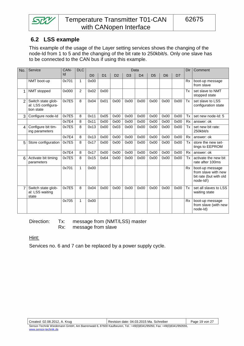
6.2 LSS example
This example of the usage of the Layer setting services shows the changing of the node-Id from 1 to 5 and the changing of the bit rate to 250kbit/s. Only one slave has to be connected to the CAN bus if using this example.
No. Service CAN-Id
DLC Data Dir Comment
D0 D1 D2 D3 D4 D5 D6 D7
NMT boot-up 0x701 1 0x00 Rx boot-up message from slave
1 NMT stopped 0x000 2 0x02 0x00 Tx set slave to NMT stopped state
2 Switch state glob-al: LSS configura-tion state
0x7E5 8 0x04 0x01 0x00 0x00 0x00 0x00 0x00 0x00 Tx set slave to LSS configuration state
3 Configure node-Id 0x7E5 8 0x11 0x05 0x00 0x00 0x00 0x00 0x00 0x00 Tx set new node-Id: 5
0x7E4 8 0x11 0x00 0x00 0x00 0x00 0x00 0x00 0x00 Rx answer: ok
4 Configure bit tim-ing parameters
0x7E5 8 0x13 0x00 0x03 0x00 0x00 0x00 0x00 0x00 Tx set new bit rate: 250kbit/s
0x7E4 8 0x13 0x00 0x00 0x00 0x00 0x00 0x00 0x00 Rx answer: ok
5 Store configuration 0x7E5 8 0x17 0x00 0x00 0x00 0x00 0x00 0x00 0x00 Tx store the new set-tings to EEPROM
0x7E4 8 0x17 0x00 0x00 0x00 0x00 0x00 0x00 0x00 Rx answer: ok
6 Activate bit timing parameters
0x7E5 8 0x15 0x64 0x00 0x00 0x00 0x00 0x00 0x00 Tx activate the new bit rate after 100ms
0x701 1 0x00 Rx boot-up message from slave with new bit rate (but with old node-Id!)
7 Switch state glob-al: LSS waiting state
0x7E5 8 0x04 0x00 0x00 0x00 0x00 0x00 0x00 0x00 Tx set all slaves to LSS waiting state
0x705 1 0x00 Rx boot-up message from slave (with new node-Id)
Direction: Tx: message from (NMT/LSS) master Rx: message from slave
Hint:
Services no. 6 and 7 can be replaced by a power supply cycle.
Temperature Transmitter T01-CAN
with CANopen Interface
62675
- Einwegpause -
Created: 02.08.2012, A. Krug Revision date: 04.03.2015 Ma. Schreiber Page 20 von 27
Sensor-Technik Wiedemann GmbH, Am Baerenwald 6, 87600 Kaufbeuren, Tel.: +49(0)8341/95050, Fax: +49(0)8341/950555, www.sensor-technik.de
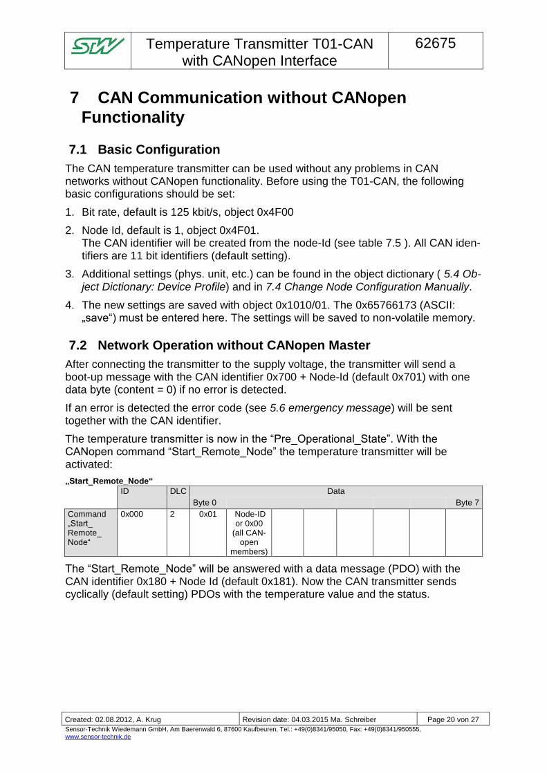
7 CAN Communication without CANopen
Functionality
7.1 Basic Configuration
The CAN temperature transmitter can be used without any problems in CAN networks without CANopen functionality. Before using the T01-CAN, the following basic configurations should be set:
1. Bit rate, default is 125 kbit/s, object 0x4F00
2. Node Id, default is 1, object 0x4F01. The CAN identifier will be created from the node-Id (see table 7.5 ). All CAN iden-tifiers are 11 bit identifiers (default setting).
3. Additional settings (phys. unit, etc.) can be found in the object dictionary ( 5.4 Ob-ject Dictionary: Device Profile) and in 7.4 Change Node Configuration Manually.
4. The new settings are saved with object 0x1010/01. The 0x65766173 (ASCII: „save“) must be entered here. The settings will be saved to non-volatile memory.
7.2 Network Operation without CANopen Master
After connecting the transmitter to the supply voltage, the transmitter will send a boot-up message with the CAN identifier 0x700 + Node-Id (default 0x701) with one data byte (content = 0) if no error is detected.
If an error is detected the error code (see 5.6 emergency message) will be sent together with the CAN identifier.
The temperature transmitter is now in the “Pre_Operational_State”. With the CANopen command “Start_Remote_Node” the temperature transmitter will be activated:
„Start_Remote_Node“
ID DLC Data
Byte 0 Byte 7
Command „Start_ Remote_ Node“
0x000 2 0x01 Node-ID or 0x00
(all CAN-open
members)
The “Start_Remote_Node” will be answered with a data message (PDO) with the CAN identifier 0x180 + Node Id (default 0x181). Now the CAN transmitter sends cyclically (default setting) PDOs with the temperature value and the status.
Temperature Transmitter T01-CAN
with CANopen Interface
62675
- Einwegpause -
Created: 02.08.2012, A. Krug Revision date: 04.03.2015 Ma. Schreiber Page 21 von 27
Sensor-Technik Wiedemann GmbH, Am Baerenwald 6, 87600 Kaufbeuren, Tel.: +49(0)8341/95050, Fax: +49(0)8341/950555, www.sensor-technik.de
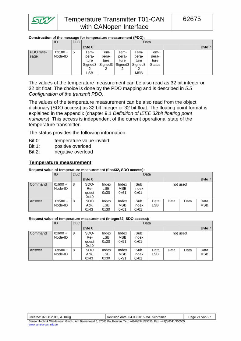
Construction of the message for temperature measurement (PDO):
ID DLC Data
Byte 0 Byte 7
PDO mes-sage
0x180 + Node-ID
5 Tem-pera-ture
Signed32
LSB
Tem-pera-ture
Signed32
Tem-pera-ture
Signed32
Tem-pera-ture
Signed32
MSB
Tem-pera-ture
Status
The values of the temperature measurement can be also read as 32 bit integer or 32 bit float. The choice is done by the PDO mapping and is described in 5.5 Configuration of the transmit PDO.
The values of the temperature measurement can be also read from the object dictionary (SDO access) as 32 bit integer or 32 bit float. The floating point format is explained in the appendix (chapter 9.1 Definition of IEEE 32bit floating point numbers). This access is independent of the current operational state of the temperature transmitter.
The status provides the following information:
Bit 0: temperature value invalid Bit 1: positive overload Bit 2: negative overload
Temperature measurement
Request value of temperature measurement (float32, SDO access):
ID DLC Data
Byte 0 Byte 7
Command 0x600 + Node-ID
8 SDO-Re-
quest 0x40
Index LSB 0x30
Index MSB 0x61
Sub Index 0x01
not used
Answer 0x580 + Node-ID
8 SDO Ack. 0x43
Index LSB 0x30
Index MSB 0x61
Sub Index 0x01
Data LSB
Data Data Data MSB
Request value of temperature measurement (integer32, SDO access):
ID DLC Data
Byte 0 Byte 7
Command 0x600 + Node-ID
8 SDO-Re-
quest 0x40
Index LSB 0x30
Index MSB 0x91
Sub Index 0x01
not used
Answer 0x580 + Node-ID
8 SDO Ack. 0x43
Index LSB 0x30
Index MSB 0x91
Sub Index 0x01
Data LSB
Data Data Data MSB

Temperature Transmitter T01-CAN
with CANopen Interface
62675
- Einwegpause -
Created: 02.08.2012, A. Krug Revision date: 04.03.2015 Ma. Schreiber Page 22 von 27
Sensor-Technik Wiedemann GmbH, Am Baerenwald 6, 87600 Kaufbeuren, Tel.: +49(0)8341/95050, Fax: +49(0)8341/950555, www.sensor-technik.de
7.2.1 SDO abort codes
If the SDO access fails, the T01-CAN will answer with a SDO abort code.
SDO abort code Meaning
0x06010001 Attempt to read a write only object.
0x06010002 Attempt to write a read only object.
0x06020000 Object does not exist in the object dictionary.
0x06040041 Object cannot be mapped to the PDO.
0x06040042 The number and length of the objects to be mapped would exceed PDO length.
0x06040043 General parameter incompatibility reason.
0x06060000 Access failed due to an hardware error.
0x06070012 Data type does not match, length of service parameter too high
0x06070013 Data type does not match, length of service parameter too low
0x06090011 Sub-index does not exist.
0x06090030 Value range of parameter exceeded (only for write access).
0x06090031 Value of parameter written too high.
0x06090032 Value of parameter written too low.
7.3 Cyclically Sending
The temperature transmitter T01-CAN is able to send the values of measurements (PDO) cyclic with a programmable time interval.
The event timer is activated by writing 0xFF to the object 0x1800 subindex 2 (transmission type).
The timer interval is written to the object 0x1800 subindex 5 (event timer). The value (unsigned16) is set in units of 1 ms. The value range is from 0 ms to 65535 ms. 0 stops the event timer.
Default settings:
Transmission type: 0xFF (event timer active)
Event timer: 1000 ms
Activate Event Timer (SDO Access):
ID DLC Data
Byte 0 Byte 7
Command 0x600 + Node-ID
8 SDO-Write 0x2F
Index LSB 0x00
Index MSB 0x18
Sub Index 0x02
Trans-mission
Type 0xFF
not used
Answer 0x580 + Node-ID
8 SDO Ack. 0x60
Index LSB 0x00
Index MSB 0x18
Sub Index 0x02
not used
Temperature Transmitter T01-CAN
with CANopen Interface
62675
- Einwegpause -
Created: 02.08.2012, A. Krug Revision date: 04.03.2015 Ma. Schreiber Page 23 von 27
Sensor-Technik Wiedemann GmbH, Am Baerenwald 6, 87600 Kaufbeuren, Tel.: +49(0)8341/95050, Fax: +49(0)8341/950555, www.sensor-technik.de
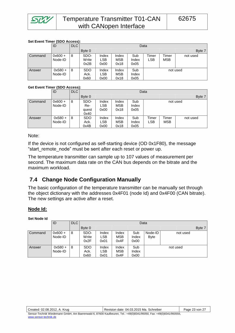
Set Event Timer (SDO Access):
ID DLC Data
Byte 0 Byte 7
Command 0x600 + Node-ID
8 SDO-Write 0x2B
Index LSB 0x00
Index MSB 0x18
Sub Index 0x05
Timer LSB
Timer MSB
not used
Answer 0x580 + Node-ID
8 SDO Ack. 0x60
Index LSB 0x00
Index MSB 0x18
Sub Index 0x05
not used
Get Event Timer (SDO Access):
ID DLC Data
Byte 0 Byte 7
Command 0x600 + Node-ID
8 SDO-Re-
quest 0x40
Index LSB 0x00
Index MSB 0x18
Sub Index 0x05
not used
Answer 0x580 + Node-ID
8 SDO Ack.
0x4B
Index LSB 0x00
Index MSB 0x18
Sub Index 0x05
Timer LSB
Timer MSB
not used
Note:
If the device is not configured as self-starting device (OD 0x1F80), the message “start_remote_node” must be sent after each reset or power up.
The temperature transmitter can sample up to 107 values of measurement per second. The maximum data rate on the CAN bus depends on the bitrate and the maximum workload.
7.4 Change Node Configuration Manually
The basic configuration of the temperature transmitter can be manually set through the object dictionary with the addresses 0x4F01 (node Id) and 0x4F00 (CAN bitrate). The new settings are active after a reset.
Node Id:
Set Node Id
ID DLC Data
Byte 0 Byte 7
Command 0x600 + Node-ID
8 SDO-Write 0x2F
Index LSB 0x01
Index MSB 0x4F
Sub Index 0x00
Node-ID Byte
not used
Answer 0x580 + Node-ID
8 SDO Ack. 0x60
Index LSB 0x01
Index MSB 0x4F
Sub Index 0x00
not used
Temperature Transmitter T01-CAN
with CANopen Interface
62675
- Einwegpause -
Created: 02.08.2012, A. Krug Revision date: 04.03.2015 Ma. Schreiber Page 24 von 27
Sensor-Technik Wiedemann GmbH, Am Baerenwald 6, 87600 Kaufbeuren, Tel.: +49(0)8341/95050, Fax: +49(0)8341/950555, www.sensor-technik.de
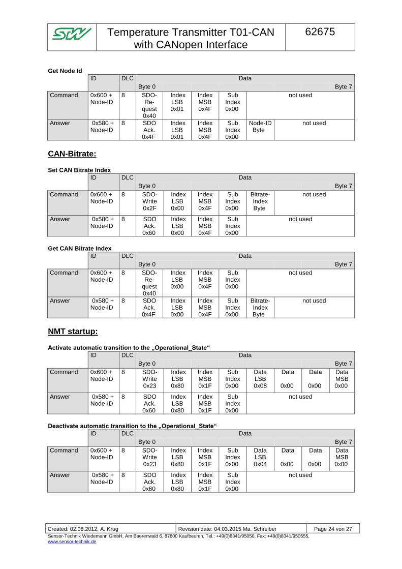
Get Node Id
ID DLC Data
Byte 0 Byte 7
Command 0x600 + Node-ID
8 SDO-Re-
quest 0x40
Index LSB 0x01
Index MSB 0x4F
Sub Index 0x00
not used
Answer 0x580 + Node-ID
8 SDO Ack. 0x4F
Index LSB 0x01
Index MSB 0x4F
Sub Index 0x00
Node-ID Byte
not used
CAN-Bitrate:
Set CAN Bitrate Index
ID DLC Data
Byte 0 Byte 7
Command 0x600 + Node-ID
8 SDO-Write 0x2F
Index LSB 0x00
Index MSB 0x4F
Sub Index 0x00
Bitrate-Index Byte
not used
Answer 0x580 + Node-ID
8 SDO Ack. 0x60
Index LSB 0x00
Index MSB 0x4F
Sub Index 0x00
not used
Get CAN Bitrate Index
ID DLC Data
Byte 0 Byte 7
Command 0x600 + Node-ID
8 SDO-Re-
quest 0x40
Index LSB 0x00
Index MSB 0x4F
Sub Index 0x00
not used
Answer 0x580 + Node-ID
8 SDO Ack. 0x4F
Index LSB 0x00
Index MSB 0x4F
Sub Index 0x00
Bitrate-Index Byte
not used
NMT startup:
Activate automatic transition to the „Operational_State“
ID DLC Data
Byte 0 Byte 7
Command 0x600 + Node-ID
8 SDO-Write 0x23
Index LSB 0x80
Index MSB 0x1F
Sub Index 0x00
Data LSB 0x08
Data
0x00
Data
0x00
Data MSB 0x00
Answer 0x580 + Node-ID
8 SDO Ack. 0x60
Index LSB 0x80
Index MSB 0x1F
Sub Index 0x00
not used
Deactivate automatic transition to the „Operational_State“
ID DLC Data
Byte 0 Byte 7
Command 0x600 + Node-ID
8 SDO-Write 0x23
Index LSB 0x80
Index MSB 0x1F
Sub Index 0x00
Data LSB 0x04
Data
0x00
Data
0x00
Data MSB 0x00
Answer 0x580 + Node-ID
8 SDO Ack. 0x60
Index LSB 0x80
Index MSB 0x1F
Sub Index 0x00
not used
Temperature Transmitter T01-CAN
with CANopen Interface
62675
- Einwegpause -
Created: 02.08.2012, A. Krug Revision date: 04.03.2015 Ma. Schreiber Page 25 von 27
Sensor-Technik Wiedemann GmbH, Am Baerenwald 6, 87600 Kaufbeuren, Tel.: +49(0)8341/95050, Fax: +49(0)8341/950555, www.sensor-technik.de
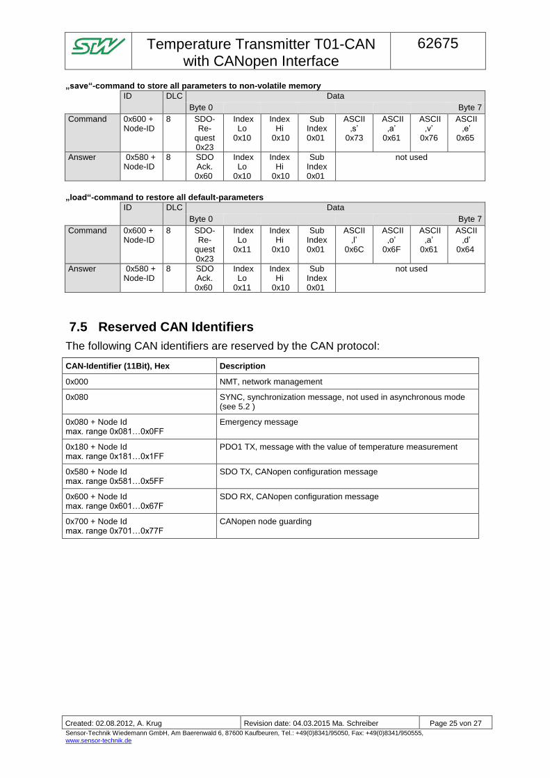
„save“-command to store all parameters to non-volatile memory
ID DLC Data
Byte 0 Byte 7
Command 0x600 + Node-ID
8 SDO-Re-
quest 0x23
Index Lo
0x10
Index Hi
0x10
Sub Index 0x01
ASCII ‚s’
0x73
ASCII ‚a’
0x61
ASCII ‚v’
0x76
ASCII ‚e’
0x65
Answer 0x580 + Node-ID
8 SDO Ack. 0x60
Index Lo
0x10
Index Hi
0x10
Sub Index 0x01
not used
„load“-command to restore all default-parameters
ID DLC Data
Byte 0 Byte 7
Command 0x600 + Node-ID
8 SDO-Re-
quest 0x23
Index Lo
0x11
Index Hi
0x10
Sub Index 0x01
ASCII ‚l’
0x6C
ASCII ‚o’
0x6F
ASCII ‚a’
0x61
ASCII ‚d’
0x64
Answer 0x580 + Node-ID
8 SDO Ack. 0x60
Index Lo
0x11
Index Hi
0x10
Sub Index 0x01
not used
7.5 Reserved CAN Identifiers
The following CAN identifiers are reserved by the CAN protocol:
CAN-Identifier (11Bit), Hex Description
0x000 NMT, network management
0x080 SYNC, synchronization message, not used in asynchronous mode (see 5.2 )
0x080 + Node Id max. range 0x081…0x0FF
Emergency message
0x180 + Node Id max. range 0x181…0x1FF
PDO1 TX, message with the value of temperature measurement
0x580 + Node Id max. range 0x581…0x5FF
SDO TX, CANopen configuration message
0x600 + Node Id max. range 0x601…0x67F
SDO RX, CANopen configuration message
0x700 + Node Id max. range 0x701…0x77F
CANopen node guarding
Temperature Transmitter T01-CAN
with CANopen Interface
62675
- Einwegpause -
Created: 02.08.2012, A. Krug Revision date: 04.03.2015 Ma. Schreiber Page 26 von 27
Sensor-Technik Wiedemann GmbH, Am Baerenwald 6, 87600 Kaufbeuren, Tel.: +49(0)8341/95050, Fax: +49(0)8341/950555, www.sensor-technik.de
8 Extensions
Device profile DS404
Heartbeat function
Different units for the temperature values available
Programmable monitoring of the measurement range
Autozero function
Offset shift
9 Appendix
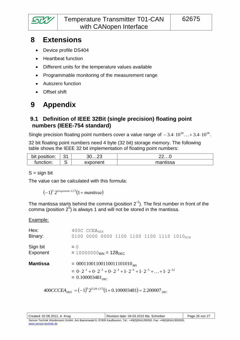
9.1 Definition of IEEE 32Bit (single precision) floating point
numbers (IEEE-754 standard)
Single precision floating point numbers cover a value range of 3838 104.3104.3 .
32 bit floating point numbers need 4 byte (32 bit) storage memory. The following table shows the IEEE 32 bit implementation of floating point numbers:
bit position: 31 30…23 22…0
function: S exponent mantissa
S = sign bit
The value can be calculated with this formula:
mantissaonentS 121 127exp
The mantissa starts behind the comma (position 2-1
). The first number in front of the comma (position 2
0) is always 1 and will not be stored in the mantissa.
Example:
Hex: 400C CCEAHEX
Binary: 0100 0000 0000 1100 1100 1100 1110 1010BIN
Sign bit = 0
Exponent = 10000000BIN = 128DEC
Mantissa = BIN01001100111010001100110
= 2254321 212121202020
= DEC100003481.0
DECHEXCCCEA 200007.2100003481.0121400 1271280
Temperature Transmitter T01-CAN
with CANopen Interface
62675
- Einwegpause -
Created: 02.08.2012, A. Krug Revision date: 04.03.2015 Ma. Schreiber Page 27 von 27
Sensor-Technik Wiedemann GmbH, Am Baerenwald 6, 87600 Kaufbeuren, Tel.: +49(0)8341/95050, Fax: +49(0)8341/950555, www.sensor-technik.de
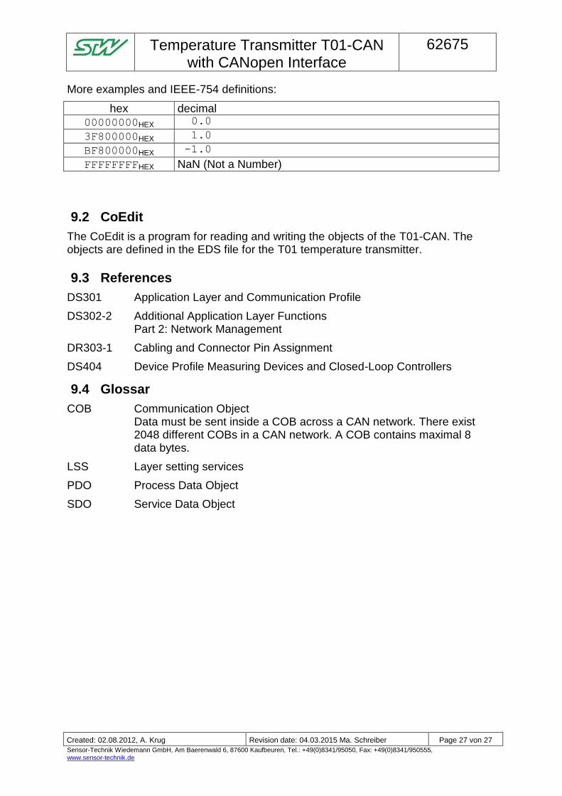
More examples and IEEE-754 definitions:
hex decimal
00000000HEX 0.0
3F800000HEX 1.0
BF800000HEX -1.0
FFFFFFFFHEX NaN (Not a Number)
9.2 CoEdit
The CoEdit is a program for reading and writing the objects of the T01-CAN. The objects are defined in the EDS file for the T01 temperature transmitter.
9.3 References
DS301 Application Layer and Communication Profile
DS302-2 Additional Application Layer Functions Part 2: Network Management
DR303-1 Cabling and Connector Pin Assignment
DS404 Device Profile Measuring Devices and Closed-Loop Controllers
9.4 Glossar
COB Communication Object Data must be sent inside a COB across a CAN network. There exist 2048 different COBs in a CAN network. A COB contains maximal 8 data bytes.
LSS Layer setting services
PDO Process Data Object
SDO Service Data Object