manual de instalaciÓn - midea.com.ar · to install properly, please read this manual at first. the...
TRANSCRIPT
MANUALDE INSTALACIÓN
Split Duct Air ConditionerDigital Scroll and DC Inverter Commercial Air-conditioner
The Digital Scroll and DC Inverter share the same indoor units. Thank you very much for purchasing our air conditioner,please read this manual carefully and keep it for future reference.
To install properly, please read this manual at first.
The air conditioner must be installed by qualified persons.
When installing the indoor unit or its tubing, please follow this
manual as strictly as possible.
When all the installation work is finished, please turn on the power
only after a thorough check.
No further announcement if there is any change of this manual
caused by product improvement.
Indoor Unit
Enough room for installation and maintenance.
The ceiling is horizontal and it can afford the weight of the indoor
unit.
The air inlet and outlet are not impeded and does not affected by
outdoor air too much.
The air flow can reach every part of the room.
The connecting pipe and drainpipe can be easily extracted out.
installation manual
NOTE
The installor should il lustrate to users how to correctly use and maintain the air-conditioner, as well as remind users to
carefully read and keep both Installation Manual and Owner's
Manual well.
●
●
●
●
●
There is no direct radiation from heat source.
Outdoor Unit
Enough room for installation and maintenance.
The air inlet and outlet are not impeded and does not affected by
outdoor air too much.
Dry and well ventilated place.
The supporter is flat and horizontal and can afford the weigh of
outdoor unit, without noise and vibration.
The noise and the outlet air will not influence your neighbor.
No combustible gas.
Place convenient for piping and wiring.
Please keep away from the following places, or malfunction may
be caused.(if unavoidable, please consult the professionals):
There is mineral oil like the oil of cutting machine.
There is much salty air. (Near the coast)
There is caustic gas such as sulfuric gas. (Near the hotspring.)
Factory where the voltage fluctuate greatly.
In the car or in the cabin.
In the kitchen or a place full of oil steam.
There is strong electromagnetic wave.
There is combustible gas or materials.
There is much evaporating acid or alkaline gas.
Other special areas.
Notes Before Installation
Select the correct carry-in path.
Move this unit as originally packaged as possible.
If the air conditioner is installed on a metal part of the building, it must be electrically insulated according to the relevant standards
to electrical appliances.
●
●
●
●
●
●
●
●
●
●
●
●
●
●
●
●
●
●
●
●
●
CONTENTS PAGE
DISPOSAL:Do not dispose this product as unsorted municipal waste. Collection of such waste separately for special treatment
is necessary.
This appliance is not intended for use by persons (including children) with reduced physical, sensory or mental capabilities, or lack of
esperience and knowledge ,unless they have been given supervision
or instruction concerning use of the appliance by a person responsible for their safety.
Children should be supervised to ensure that they do not play with
the appliance.
Disconnect the power supply before cleaning and maintenance.
NOTE
Remark per EMC Directive 89/336/EEC
For to prevent fl icker impressions during the start of the
compressor (technical process), following installation condi-tions apply.
The power connection for the air conditioner has to be done at the main power distribution.The distribution has to be of
a low impedance, normally the required impedance reaches
at a 32A fusing point.
No other equipment has to be connected with this power
line.
For detailed installat ion acceptance, please refer to your
contract with the power supplier if restrictions do apply for products l ike washing machines, a i r con di t ioners or
electrical ovens.
●
●
●
installation manual
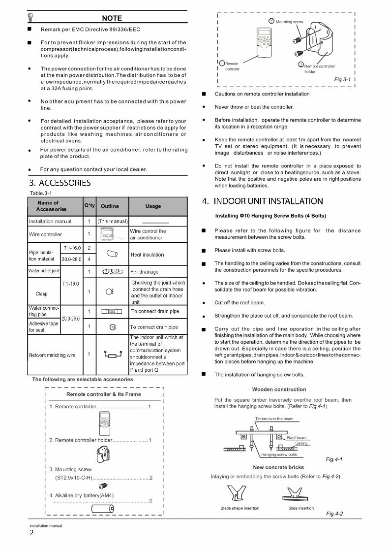
Please refer to the following figure for the distance measurement between the screw bolts.
Please install with screw bolts.
The handling to the ceiling varies from the constructions, consult
the construction personnels for the specific procedures.
The size of the ceiling to be handled.Do keep the ceiling flat. Con-
solidate the roof beam for possible vibration.
Cut off the roof beam.
Strengthen the place cut off, and consolidate the roof beam.
Carry out the pipe and line operation in the ceiling after finishing the installation of the main body. While choosing where
to start the operation, determine the direction of the pipes to be
drawn out. Especially in case there is a ceiling, position the refrigerant pipes, drain pipes, indoor & outdoor lines to the connec-
tion places before hanging up the machine.
The installation of hanging screw bolts.
●
●
●
Fig.4-1
Hanging screw bolts
Ceiling
Timber over the beam
Roof beam
Put the square timber traversely overthe roof beam, then install the hanging screw bolts. (Refer to Fig.4-1)
Wooden construction
New concrete bricks
Fig.4-2
Inlaying or embedding the screw bolts (Refer to Fig.4-2)
Blade shape insertion Slide insertion
Installing Φ10 Hanging Screw Bolts (4 Bolts)
Cautions on remote controller installation
Never throw or beat the controller.
Before installation, operate the remote controller to determine
its location in a reception range.
Keep the remote controller at least 1m apart from the nearest
TV set or stereo equipment. (It is necessary to prevent
image disturbances or noise interferences.)
Do not install the remote controller in a place exposed to
direct sunlight or close to a heatingsource, such as a stove. Note that the positive and negative poles are in right positions
when loading batteries.
●
●
●
●
1. Remote controller....................................1
2. Remote controller holder................. ........1
3. Mounting screw
(ST2.9x10-C-H)........................................2
4. Alkaline dry battery(AM4) ...... .................. ..........................................2
Remote controller & Its Frame
For power details of the air conditioner, refer to the rating
plate of the product.
For any question contact your local dealer.
●
●
Table.3-1
1
1
1
Name of Accessories
Installation manual
Wire controller
Q‘ty
4
Outline Usage
Wire control the
air-conditioner
1
1
1
The following are selectable accessories
2
Remote controller
holder
Mounting screw
Fig.3-1
Remote
controller
1
installation manual
Overhanging the indoor unit
Overhang the indoor unit onto the hanging screw bolts with
block.
Position the indoor unit in a flat level by using the level indicator,
unless it may cause leakage.
●
●
Screw nut
Overhang part washer
Hanging screw bolt
Fig.4-5
Fig.4-8
Fig.4-7
Fig.4-6
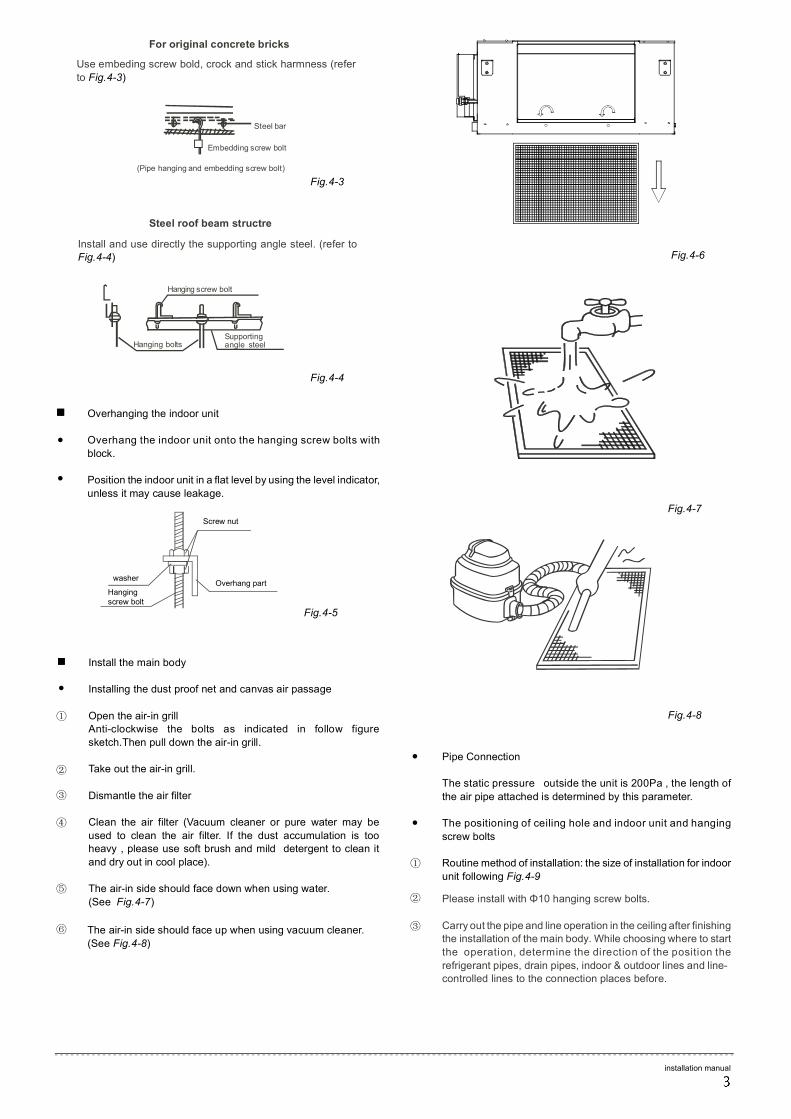
Install the main body
Installing the dust proof net and canvas air passage
Open the air-in grill Anti-clockwise the bolts as indicated in follow figure
sketch.Then pull down the air-in grill.
Take out the air-in grill.
Dismantle the air filter
Clean the air filter (Vacuum cleaner or pure water may be
used to clean the air filter. If the dust accumulation is too heavy , please use soft brush and mild detergent to clean it
and dry out in cool place).
The air-in side should face down when using water.
(See Fig.4-7)
●
①
②
③
④
⑤
⑥
Pipe Connection
The static pressure outside the unit is 200Pa , the length of
the air pipe attached is determined by this parameter.
The positioning of ceiling hole and indoor unit and hanging
screw bolts
Routine method of installation: the size of installation for indoor
unit following Fig.4-9 Please install with Φ10 hanging screw bolts.
Carry out the pipe and line operation in the ceiling after finishing the installation of the main body. While choosing where to start
the operation, determine the direction of the position the
refrigerant pipes, drain pipes, indoor & outdoor lines and line-controlled lines to the connection places before.
●
●
①
②
③
For original concrete bricks
Steel roof beam structre
Fig.4-3
Fig.4-4
Steel bar
Embedding screw bolt
(Pipe hanging and embedding screw bolt)
Use embeding screw bold, crock and stick harmness (refer
to Fig.4-3)
Hanging screw bolt
Hanging bolts Supporting
Install and use directly the supporting angle steel. (refer to Fig.4-4)
angle steel
The air-in side should face up when using vacuum cleaner.
(See Fig.4-8)
installation manual
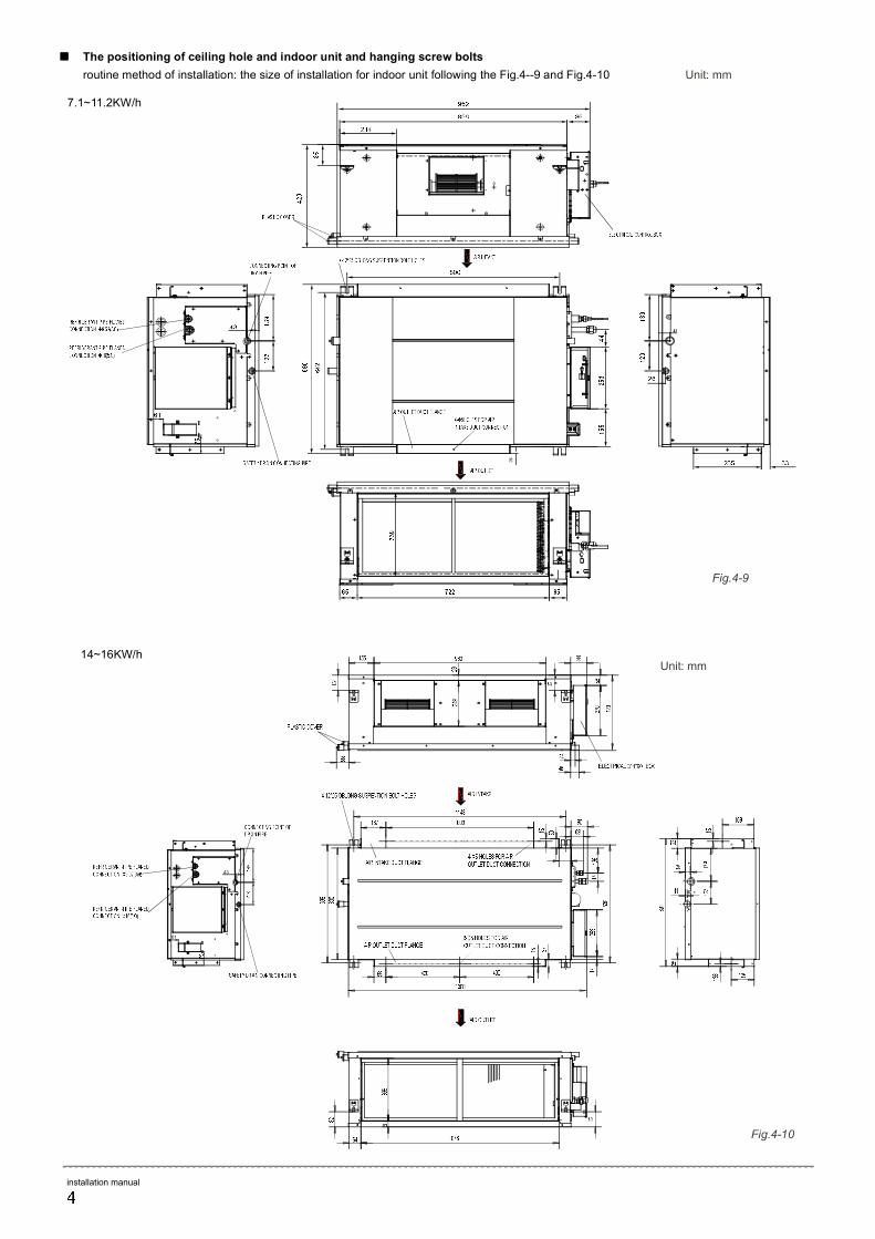
Fig.4-9
Fig.4-10
7.1~11.2KW/h
14~16KW/h Unit: mm
Unit: mm
The positioning of ceiling hole and indoor unit and hanging screw bolts
routine method of installation: the size of installation for indoor unit following the Fig.4--9 and Fig.4-10
61
43
installation manual
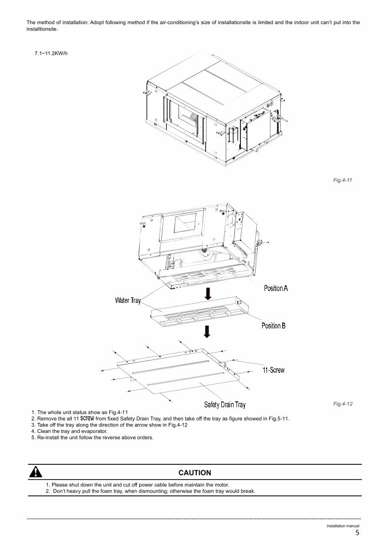
Fig.4-12
Fig.4-11
The method of installation: Adopt following method if the air-conditioning’s size of installationsite is limited and the indoor unit can’t put into the
installtionsite.
7.1~11.2KW/h
1. The whole unit status show as Fig.4-11 2. Remove the all 11 from fixed Safety Drain Tray, and then take off the tray as figure showed in Fig.5-11. 3. Take off the tray along the direction of the arrow show in Fig.4-12 4. Clean the tray and evaporator. 5. Re-install the unit follow the reverse above orders.
1. Please shut down the unit and cut off power cable before maintain the motor. 2. Don’t heavy pull the foam tray, when dismounting; otherwise the foam tray would break.
CAUTION
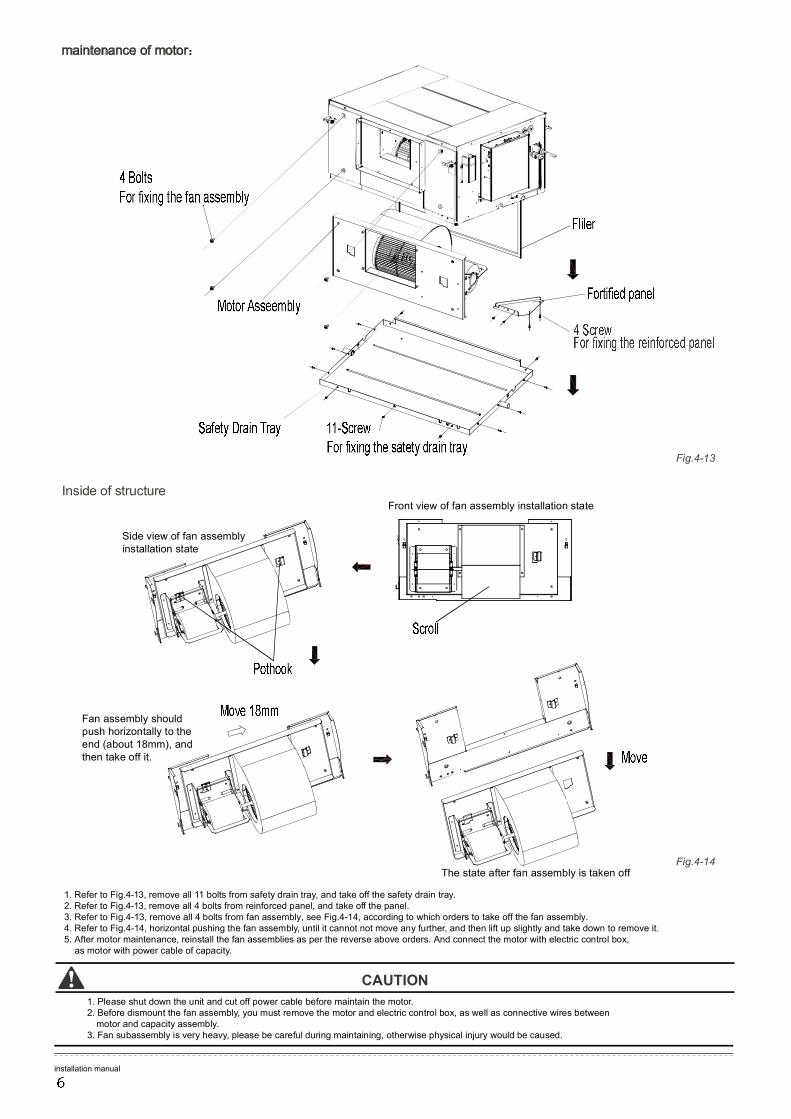
Side view of fan assembly installation state
Front view of fan assembly installation state
Fan assembly should push horizontally to the end (about 18mm), and then take o f f it.
The state after fan assembly is taken off
Fig.4-13
Fig.4-14
Inside of structure
CA U TION
1. Refer to Fig.4- 1 3, remove all 1 1 bolts from safety drain tra y , and take o f f the safety drain tra y . 2. Refer to Fig.4- 1 3, remove all 4 bolts from reinforced panel, and take o f f the panel. 3. Refer to Fig.4-13, remove all 4 bolts from fan assembly, see Fig.4-14, accor ding to which orders to take off the fan assembly. 4. Refer to Fig.4-14, horizontal pushing the fan assembl y , until it cannot not move any furthe r , and then lift up slightly and take down to remove it. 5. After motor maintenance, reinstall the fan assemblies as per the reverse above orders. And connect the motor with electric control box,
as motor with power cable of capacit y .
1. Please shut down the unit and cut o f f power cabl e before maintain the moto r . 2. Before dismount the fan assembl y , you must remove the motor and electric control box, as well a s connective wires between
motor and capacity assembl y . 3. Fan subassembly is very heav y , please be carefu l during maintaining, otherwise physical injury would be caused.
maintenance of motor:
installation manual
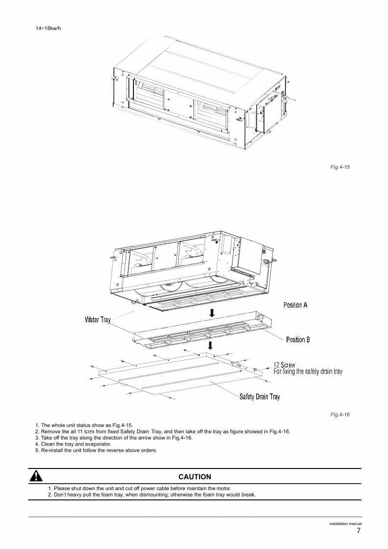
CAUTION
Fig.4-15
Fig.4-16
14~16kw/h
1. The whole unit status show as Fig.4-15. 2. Remove the all 1 1 from fixed Safety Drain T ra y , and then take o f f the tray as figure showed in Fig.4-16. 3. T ake o f f the tray along the direction of the arrow show in Fig.4-16. 4. Clean the tray and evaporato r . 5. Re-install the unit follow the reverse above orders.
1. Please shut down the unit and cut o f f power cable before maintain the moto r . 2. Don’t heavy pull the foam tra y , when dismounting; otherwise the foam tray would break.
installation manual

Side view of fan assembly installation state
Front view of fan assembly installation state
Fan assembly should push horizontally to the end (about 18mm), and then take o f f it.
The state after fan assembly is taken off Fig.4-18
Fig.4-17
maintenance of motor:
Inside of structure
CAUTION
1. Refer to Fig.4-17, remove all 1 1 from safety drain tra y , and take o f f the safety drain tra y . 3. Refer to Fig.4-17, remove all 4 bolts from fan assembly, see Fig.4-18, accor ding to which orders to take off the fan assembly. 3. Refer to Fig.4-18, horizontal pushing the fan assembl y , until it cannot not move any furthe r , and then lift up slightly and take down to remove it. 4. After motor maintenance, reinstall the fan assemblies as per the reverse a bove orders. And connect the motor with electric control box, a s
well as motor with power cable of capacity.
1. Please shut down the unit and cut o f f power cable before maintain the moto r . 2. Before dismount the fan assembl y , you must remove the motor and electric control box, as well as connective wires between motor and
capacity assembl y . 3. Fan subassembly is very heav y , please be careful during maintaining, otherwise physical injury would be caused.
installation manual
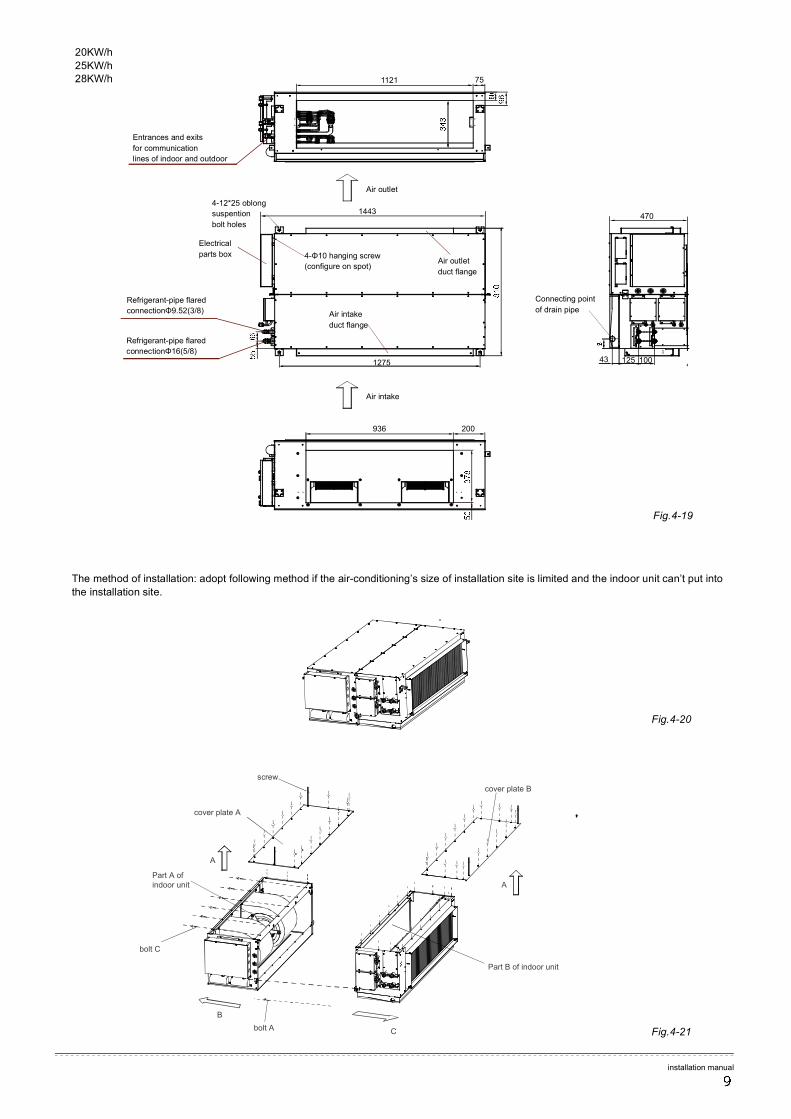
The method of installation: adopt following method if the air-conditioning’s size of installation site is limited and the indoor unit can’t put into
the installation site.
Fig.4-19
Fig.4-20
Fig.4-21
1121 75
4-Φ10 hanging screw
(configure on spot)
Connecting point
of drain pipe
Air intake
Air outlet
Refrigerant-pipe flared
connectionΦ16(5/8)
Refrigerant-pipe flared
connectionΦ9.52(3/8)
Air outlet
duct flange
4-12*25 oblong
suspention
bolt holes
Electrical
parts box
Entrances and exits
for communication
lines of indoor and outdoor
Air intake
duct flange
20KW/h
25KW/h 28KW/h
936
1275
1443
125 100 43
200
C
B
A
A
screw
cover plate A
cover plate B
Part A of indoor unit
Part B of indoor unit
bolt A
bolt C
470
installation manual
installation manual
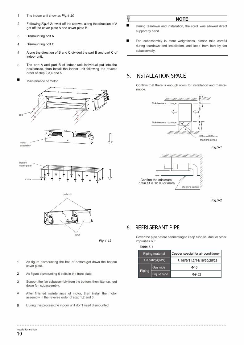
Confirm that there is enough room for installation and mainte-nance.
Fig.5-2
Fig.5-1
Maintenance roomage
Maintenance roomage
checking orifice
600mmX600mm
checking orifice
Confirm the minimum drain tilt is 1/100 or more
Cover the pipe before connecting to keep rubbish, dust or other
impurities out.
Gas side Piping
Capaticyl(KW)
Piping material Copper special for air conditioner
7.1/8/9/11.2/14/16/20/25/28
Φ16
Φ9.52 Liquid side
Table.6-1
The indoor unit show as Fig.4-20
Following Fig.4-21 twist-off the screws, along the direction of A
get off the cover plate A and cover plate B.
Dismounting bolt A
Dismounting bolt C
Along the direction of B and C divided the part B and part C of indoor unit.
The part A and part B of indoor unit individual put into the positionsite, then install the indoor unit following the reverse
order of step 2,3,4 and 5.
Maintenance of motor
1
2
3
4
5
As figure dismounting the bolt of bottom,get down the bottom cover plate. As figure dismounting 6 bolts in the front plate. Support the fan subassembly from the bottom, then litter up, get down fan subassembly. After finished maintenance of motor, then install the motor assembly in the reverse order of step 1,2 and 3. During this process,the indoor unit don’t need dismounted.
1
2
3
4
5
6
Fig.4-12
bolt
motor assembly
bottom cover plate
screw
pothook
scroll
NOTE
During teardown and installation, the scroll was allowed direct
support by hand
Fan subassembly is more weightiness, please take careful
during teardown and installation, and keep from hurt by fan
subassembly.
installation manual
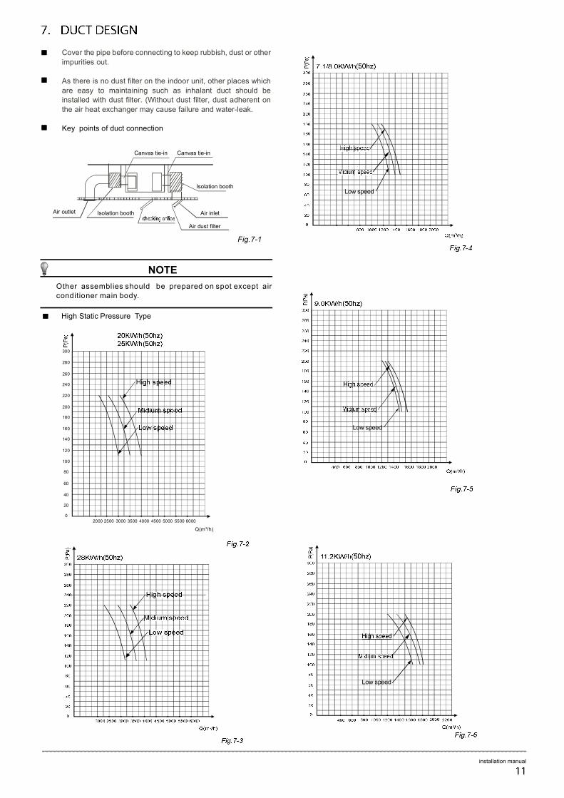
Air outlet Air inlet
Canvas tie-in Canvas tie-in
Air dust filter
Isolation booth
Isolation booth
Fig.7-1
NOTE
Other assemblies should be prepared on spot except air conditioner main body.
Cover the pipe before connecting to keep rubbish, dust or other
impurities out.
As there is no dust filter on the indoor unit, other places which
are easy to maintaining such as inhalant duct should be installed with dust filter. (Without dust filter, dust adherent on
the air heat exchanger may cause failure and water-leak.
Key points of duct connection
High Static Pressure Type
240
260
280
300
2000
Q(m3/h)
5000 5500 6000
220
200
180
160
140
120
100
80
60
40
20
0
2500 3000 3500 4000 4500
Low speed
Low speed
Low speed
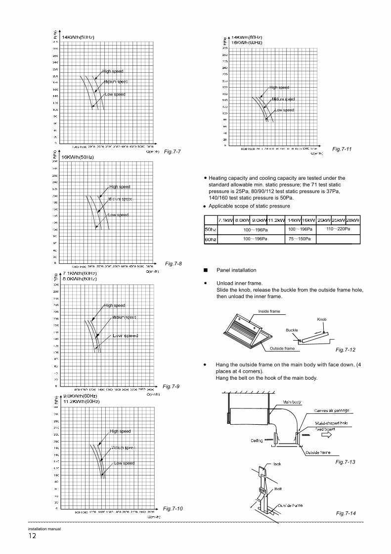
Panel installation
Unload inner frame.
Slide the knob, release the buckle from the outside frame hole, then unload the inner frame.
●
●
Knob
Outside frame
Inside frame
Buckle
Hang the outside frame on the main body with face down. (4
places at 4 corners).
Hang the belt on the hook of the main body.
Fig.7-12
Fig.7-13
Fig.7-14
installation manual
Low speed
High speed
High speed
Low speed
High speed
Heating capacity and cooling capacity are tested under the
standard allowable min. static pressure; the 71 test static
pressure is 25Pa, 80/90/112 test static pressure is 37Pa, 140/160 test static pressure is 50Pa.
Applicable scope of static pressure
●
●
100~196Pa
100~196Pa
100~196Pa
75~150Pa
110~220Pa
Low speed
High speed
Low speed
High speed
Fig.7-7
Fig.7-8
Fig.7-9
Fig.7-10
Fig.7-11
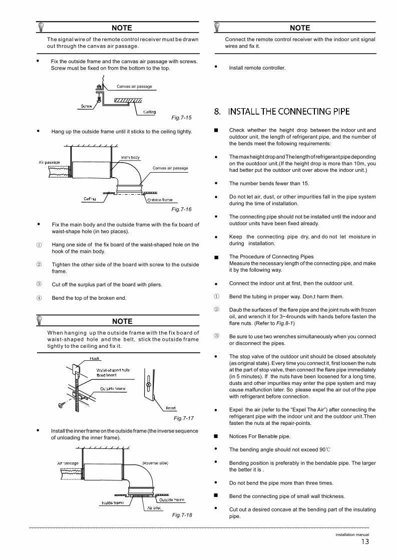
Fix the main body and the outside frame with the fix board of
waist-shape hole (in two places).
Hang one side of the fix board of the waist-shaped hole on the
hook of the main body.
Tighten the other side of the board with screw to the outside
frame.
Cut off the surplus part of the board with pliers.
Bend the top of the broken end.
●
①
②
③
④
Install the inner frame on the outside frame (the inverse sequence
of unloading the inner frame).
●
NOTE
When hanging up the outs ide f rame wi th the f ix board of waist-shaped hole and the belt, st ick the outside f rame
tightly to the ceiling and fix it.
Fig.7-17
Fig.7-18
●
●
●
●
●
●
①
②
③
●
●
●
●
●
●
Fix the outside frame and the canvas air passage with screws.
Screw must be fixed on from the bottom to the top.
●
Canvas air passage
Fig.7-15
NOTE
The signal wire of the remote control receiver must be drawn
out through the canvas air passage.
Hang up the outside frame until it sticks to the ceiling tightly.
●
Canvas air passage
Fig.7-16
Install remote controller. ●
Check whether the height drop between the indoor unit and
outdoor unit, the length of refrigerant pipe, and the number of
the bends meet the following requirements:
The max height drop and The length of refrigerant pipe deponding
on the ouotdoor unit.(If the height drop is more than 10m, you had better put the outdoor unit over above the indoor unit.)
The number bends fewer than 15.
Do not let air, dust, or other impurities fall in the pipe system
during the time of installation.
The connecting pipe should not be installed until the indoor and
outdoor units have been fixed already.
Keep the connecting pipe dry, and do not let moisture in
during installation.
The Procedure of Connecting Pipes
Measure the necessary length of the connecting pipe, and make it by the following way.
Connect the indoor unit at first, then the outdoor unit.
Bend the tubing in proper way. Don,t harm them.
Daub the surfaces of the flare pipe and the joint nuts with frozen
oil, and wrench it for 3~4rounds with hands before fasten the
flare nuts. (Refer to Fig.8-1)
Be sure to use two wrenches simultaneously when you connect
or disconnect the pipes.
The stop valve of the outdoor unit should be closed absolutely
(as original state). Every time you connect it, first loosen the nuts at the part of stop valve, then connect the flare pipe immediately
(in 5 minutes). If the nuts have been loosened for a long time,
dusts and other impurities may enter the pipe system and may cause malfunction later. So please expel the air out of the pipe
with refrigerant before connection.
Expel the air (refer to the “Expel The Air”) after connecting the
refrigerant pipe with the indoor unit and the outdoor unit.Then
fasten the nuts at the repair-points.
Notices For Benable pipe.
The bending angle should not exceed 90℃
Bending position is preferably in the bendable pipe. The larger the better it is .
Do not bend the pipe more than three times.
Bend the connecting pipe of small wall thickness.
Cut out a desired concave at the bending part of the insulating
pipe.
Connect the remote control receiver with the indoor unit signal
wires and fix it.
NOTE
installation manual
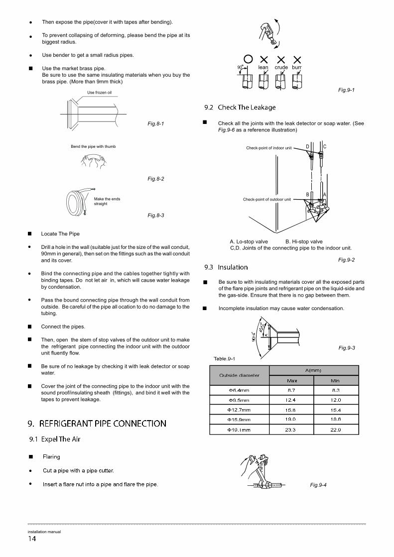
Check all the joints with the leak detector or soap water. (See Fig.9-6 as a reference illustration)
Be sure to with insulating materials cover all the exposed parts of the flare pipe joints and refrigerant pipe on the liquid-side and
the gas-side. Ensure that there is no gap between them.
Incomplete insulation may cause water condensation.
B A
D C Check-point of indoor unit
Check-point of outdoor unit
A. Lo-stop valve B. Hi-stop valve C,D. Joints of the connecting pipe to the indoor unit.
Fig.9-2
Bend the pipe with thumb
Make the ends straight
Fig.9-1
Fig.8-3
Fig.8-2
Locate The Pipe
Drill a hole in the wall (suitable just for the size of the wall conduit, 90mm in general), then set on the fittings such as the wall conduit
and its cover.
Bind the connecting pipe and the cables together tightly with
binding tapes. Do not let air in, which will cause water leakage
by condensation.
Pass the bound connecting pipe through the wall conduit from
outside. Be careful of the pipe all ocation to do no damage to the tubing.
Connect the pipes.
Then, open the stem of stop valves of the outdoor unit to make
the refrigerant pipe connecting the indoor unit with the outdoor unit fluently flow.
Be sure of no leakage by checking it with leak detector or soap water.
Cover the joint of the connecting pipe to the indoor unit with the sound proof/insulating sheath (fittings), and bind it well with the
tapes to prevent leakage.
●
●
●
●
●
90 lean crude burr
Then expose the pipe(cover it with tapes after bending).
To prevent collapsing of deforming, please bend the pipe at its
biggest radius.
Use bender to get a small radius pipes.
Use the market brass pipe. Be sure to use the same insulating materials when you buy the
brass pipe. (More than 9mm thick)
●
Use frozen oil
Fig.8-1
●
●
installation manual
Fig.9-3
Fig.9-4
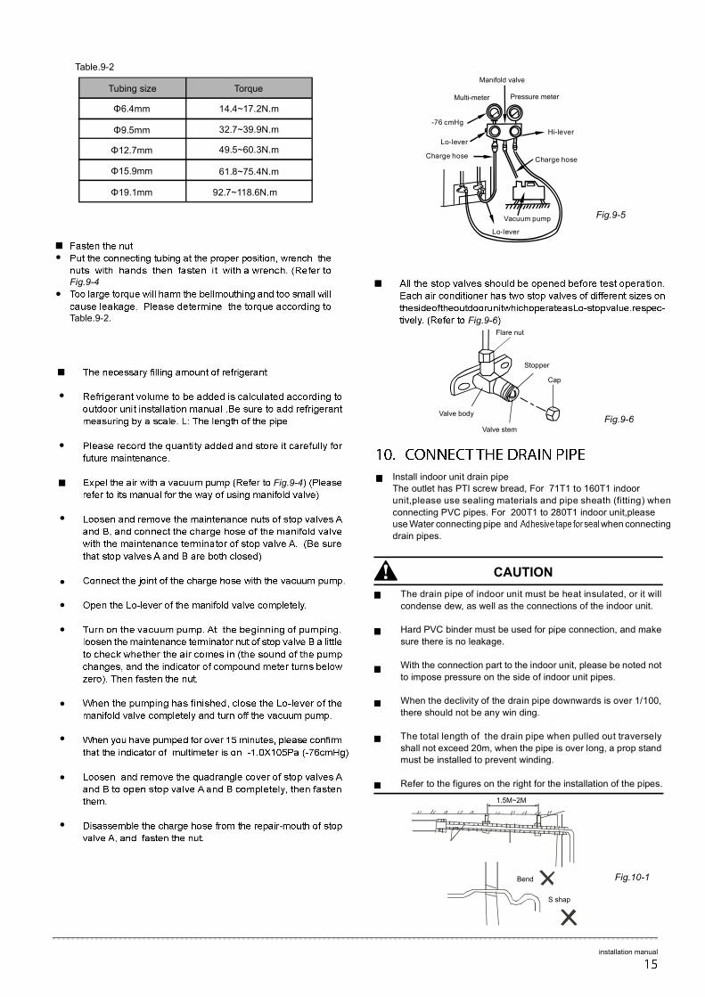
Install indoor unit drain pipe The outlet has PTI screw bread, For 71T1 to 160T1 indoor
unit,please use sealing materials and pipe sheath (fitting) when
connecting PVC pipes. For 200T1 to 280T1 indoor unit,please use Water connecting pipe when connecting
drain pipes.
installation manual
Fig.9-6Flare nut
Stopper
Cap
Valve body
Valve stem
Fig.9-6
●
●
●
●
●
●
●
●
Fig.9-5
-76 cmHg
Lo-lever
Hi-lever
Charge hose Charge hose
Vacuum pump
Lo-lever
Manifold valve
Multi-meter Pressure meter
●
●
Fig.9-4
Torque Tubing size
14.4~17.2N.m
32.7~39.9N.m
49.5~60.3N.m
61.8~75.4N.m
92.7~118.6N.m
Φ6.4mm
Φ9.5mm
Φ12.7mm
Φ15.9mm
Φ19.1mm
Table.9-2
Bend
S shap
●
●
Fig.9-4
Table.9-2.
The drain pipe of indoor unit must be heat insulated, or it will
condense dew, as well as the connections of the indoor unit.
Hard PVC binder must be used for pipe connection, and make
sure there is no leakage.
With the connection part to the indoor unit, please be noted not
to impose pressure on the side of indoor unit pipes.
When the declivity of the drain pipe downwards is over 1/100,
there should not be any win ding.
The total length of the drain pipe when pulled out traversely
shall not exceed 20m, when the pipe is over long, a prop stand must be installed to prevent winding.
Refer to the figures on the right for the installation of the pipes.
CAUTION
Fig.10-1
1.5M~2M
Attaching wiring
The air conditioner should use separate power supply with rated
voltage.
The external power supply to the air conditioner should have
ground wiring, which is linked to the ground wiring of the indoor
and outdoor unit.
The wiring work should be done by qualified persons according
to circuit drawing.
A leakage protector should be installed according to the National
Standard concerning electrical appliance.
Be sure to locate the power wiring and the signal wring well to
avoid cross-disturbance and their contact with connecting pipe or stop value body.
●
●
●
●
●
The wiring attached to this air conditioner is 10m long. Be sure
to prolong it with wiring of the same type and proper length
if necessary. Generally, do not twist two wiring together unless the joint is soldered well and covered with insulator tape.
Do not turn on the power until you have checked carefully after wiring.
●
●
Capacity(KW) 200/250/280
16/10
2.5(<20 m)-4.0(<50 m)
2.0
0.75(<1200 m)
Circuit breaker/fuse (A)
Indoor unit power wiring (mm2)
Power Phase 1-Phase
Frequency and volt
Table.11-1
A disconnection device having an air gap contact separation in
all active conductors should be incorporated in the fixed wiring
according to the National Wiring Regulation.
CAUTION
installation manual
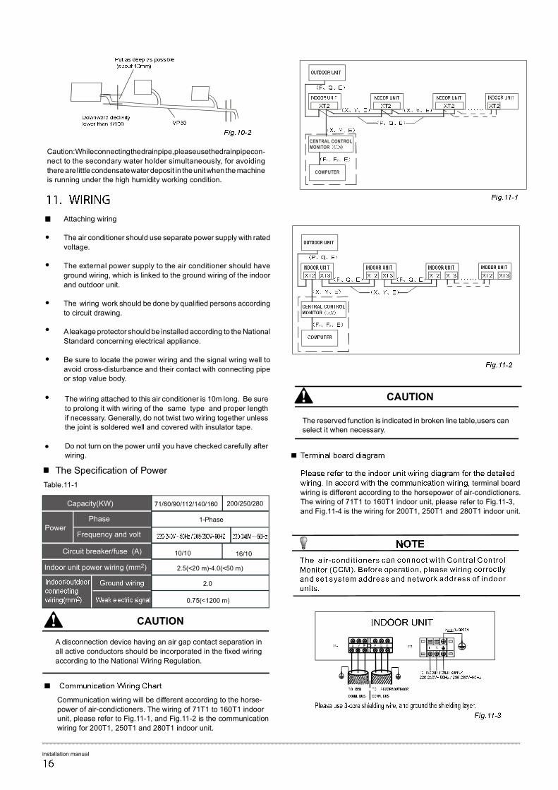
Communication wiring will be different according to the horse-
power of air-condictioners. The wiring of 71T1 to 160T1 indoor unit, please refer to Fig.11-1, and Fig.11-2 is the communication
wiring for 200T1, 250T1 and 280T1 indoor unit.
The reserved function is indicated in broken line table,users can select it when necessary.
CAUTION
terminal board
wiring is different according to the horsepower of air-condictioners. The wiring of 71T1 to 160T1 indoor unit, please refer to Fig.11-3,
and Fig.11-4 is the wiring for 200T1, 250T1 and 280T1 indoor unit.
10/10
1 2
71/80/90/112/140/160
CENTRAL CONTROL MONITOR
1 2
COMPUTER
The Specification of Power
Caution: While connecting the drain pipe, please use the drain pipe con-
nect to the secondary water holder simultaneously, for avoiding
there are little condensate water deposit in the unit when the machine is running under the high humidity working condition.
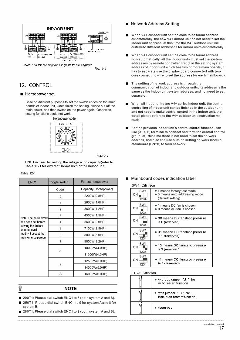
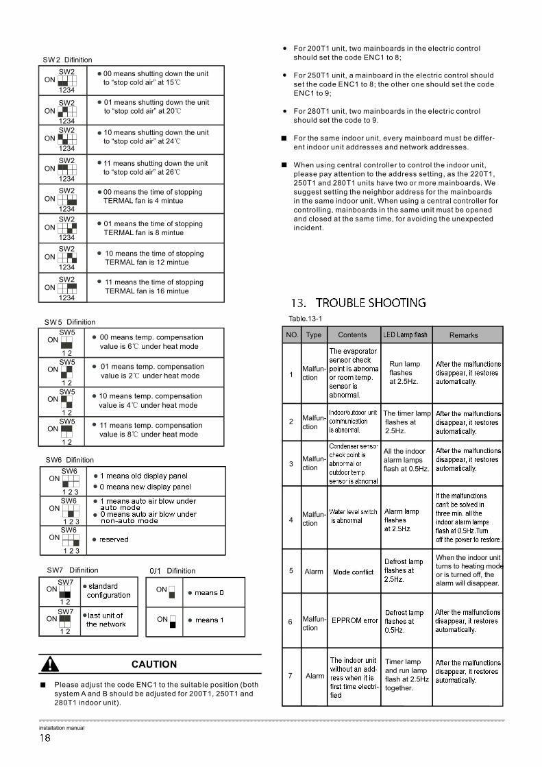
Table.12-1
ENC1
Mainboard codes indication label
When V4+ outdoor unit set the code to be found address automatically, the new V4+ indoor unit do not need to set the
indoor unit address, at this t ime the V4+ outdoor unit will
distribute different addresses for indoor units automatically.
When V4+ outdoor unit set the code to be found address
non-automatically, all the indoor units must set the system addresses by remote controller f irst (For the setting system
address of indoor unit which has two or more main boards, it
has to separate use the display board connected with ten-core connecting wire to set the address for each mainboard).
The sett ing of network address is through the communication of indoor and outdoor units, its address is the
same as the indoor unit system address, and not need to set
separate.
When all indoor units are V4+ series indoor unit, the central
controlling of indoor unit can be finished in the outdoor unit, and not need to make central control in the indoor unit, the
detail please refers to the V4+ outdoor unit instruction ma-
nual;.
For the previous indoor unit’s central control function, can
use (X, Y, E) terminal to connect and form the central control group, at this time there is not need to set the network
address, and also can use outside setting network module,
mainboard (CN20) to form network.
SW 1
SW1ON
1234
SW1ON
1234
SW1ON
1234
SW1ON
1234
SW1ON
1234
SW1ON
1234
l
l 1 means factory test mode0 means auto addressing mode (default setting)
l
l
1 means DC fan is chosen0 means AC fan is chosen
l
l
l
l
ENC1 Toggle switch
Code
7
Capacity(Horsepower)
11200W(4.0HP)
12500W(5.0HP)
14000W(5.0HP)
For set horsepower
A
5
4
3
2
1
0
8
9
2200W(0.8HP)
2800W(1.0HP)
3600W(1.2HP)
4500W(1.5HP)
5600W(2.0HP)
7100W(2.5HP)
8000W(3.0HP)
9000W(3.2HP)
10000W(4.0HP)
16000W(6.0HP)
l
l
l
Base on different purposes to set the switch codes on the mainboards of indoor unit, Once finish the setting, please cut off the main power, and then switch on the power again. Otherwise, setting functions could not work.
NOTE
200T1: Please dial switch ENC1 to 8 (both system A and B).
250T1: Please dial switch ENC1 to 9 for system A and 8 for system B. 280T1: Please dial switch ENC1 to 9 (both system A and B).
Network Address Setting
installation manual
SW2ON
1234
SW2ON
1234
SW2ON
1234
SW2ON
1234
SW2ON
1234
SW2ON
1234
SW2ON
1234
SW2ON
1234
SW 2 Difinition
l 00 means shutting down the unitto “stop cold air” at 15℃
l
l
l
l 00 means the time of stopping TERMAL fan is 4 mintue
l
l
l
●
●
●
installation manual
SW5ON
1 2SW5
ON
1 2SW5
ON
1 2SW5
ON
1 2
SW7ON
1 2
SW7ON
1 2
ON
ON
SW 5 Difinition
SW7 Difinition Difinition
SW6ON
1 2 3SW6
ON
1 2 3SW6
ON
1 2 3
l 00 means temp. compensation value is 6℃ under heat mode
l
l
l
l
l
l
l
l
l
l
l
l
For 200T1 unit, two mainboards in the electric control should set the code ENC1 to 8; For 250T1 unit, a mainboard in the electric control should set the code ENC1 to 8; the other one should set the code ENC1 to 9; For 280T1 unit, two mainboards in the electric control should set the code to 9. For the same indoor unit, every mainboard must be differ- ent indoor unit addresses and network addresses. When using central controller to control the indoor unit, please pay attention to the address setting, as the 220T1, 250T1 and 280T1 units have two or more mainboards. We suggest setting the neighbor address for the mainboards in the same indoor unit. When using a central controller for controlling, mainboards in the same unit must be opened and closed at the same time, for avoiding the unexpected incident.
Table.13-1
NO. Type Contents Remarks
Run lamp flashes at 2.5Hz.
The timer lamp flashes at 2.5Hz.
All the indoor alarm lamps flash at 0.5Hz.
When the indoor unit turns to heating mode or is turned off, the alarm will disappear.
1
2
3
4
5
Malfun- ction
Malfun- ction
Malfun- ction
Malfun- ction
Alarm
7
6
Alarm
Malfun- ction
Timer lamp and run lamp flash at 2.5Hz together.
SW6 Difinition
CAUTION
Please adjust the code ENC1 to the suitable position (both system A and B should be adjusted for 200T1, 250T1 and 280T1 indoor unit).
01 means shutting down the unitto “stop cold air” at 20℃
10 means shutting down the unitto “stop cold air” at 24℃
11 means shutting down the unitto “stop cold air” at 26℃
01 means the time of stopping TERMAL fan is 8 mintue
10 means the time of stopping TERMAL fan is 12 mintue
11 means the time of stopping TERMAL fan is 16 mintue
01 means temp. compensation value is 2℃ under heat mode
10 means temp. compensation value is 4℃ under heat mode
11 means temp. compensation value is 8℃ under heat mode
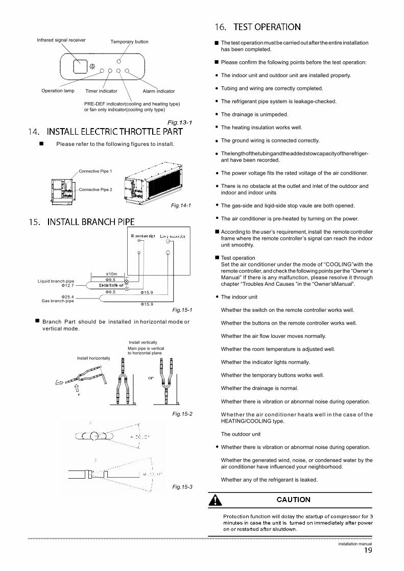
Please refer to the following figures to install.
Connective Pipe 1
Connective Pipe 2
Fig.14-1
PRE-DEF indicator(cooling and heating type) or fan only indicator(cooling only type)
Infrared signal receiver
Operation lamp Timer indicator Alarm indicator
Temporary button
installation manual
Branch Part should be installed in horizontal mode or
vertical mode.
Install horizontally
Install vertically
Main pipe is vertical to horizontal plane
Fig.15-1
Fig.15-2
Fig.15-3
●
●
●
●
●
●
●
●
●
●
●
The test operation must be carried out after the entire installation has been completed. Please confirm the following points before the test operation: The indoor unit and outdoor unit are installed properly. Tubing and wiring are correctly completed. The refrigerant pipe system is leakage-checked. The drainage is unimpeded. The heating insulation works well. The ground wiring is connected correctly. The length of the tubing and the added stow capacity of the refriger-ant have been recorded. The power voltage fits the rated voltage of the air conditioner. There is no obstacle at the outlet and inlet of the outdoor and indoor and indoor units The gas-side and liqid-side stop vaule are both opened. The air conditioner is pre-heated by turning on the power.
Liquid branch pipe Φ9.5
Φ9.5 Φ15.9
Φ15.9 Gas branch pipe
≤10m
Φ25.4
Φ12.7
According to the user’s requirement, install the remote controller frame where the remote controller’s signal can reach the indoor unit smoothly. Test operation Set the air conditioner under the mode of “COOLING”with the remote controller, and check the following points per the “Owner’s Manual” If there is any malfunction, please resolve it through chapter “Troubles And Causes ”in the “Owner’sManual”. The indoor unit Whether the switch on the remote controller works well. Whether the buttons on the remote controller works well. Whether the air flow louver moves normally. Whether the room temperature is adjusted well. Whether the indicator lights normally. Whether the temporary buttons works well. Whether the drainage is normal.
●
Whether there is vibration or abnormal noise during operation. Whether the a ir condi t ioner heats wel l in the case of the HEATING/COOLING type. The outdoor unit Whether there is vibration or abnormal noise during operation. Whether the generated wind, noise, or condensed water by the air conditioner have influenced your neighborhood. Whether any of the refrigerant is leaked.
●
Installation manual
202000171984
In all correspondence/communication state your name, address, the serial number of your air conditioning unit, date of purchase and dealer’s name (include address), location of unit and description of problem, for prompt and immediate attention
……………………………………………………………
……………………………………………………………
……………………………………………………………
……………………………………………………………
……………………………………………………………
……………………………………………………………
……………………………………………………………
……………………………………………………………
……………………………………………………………
……………………………………………………………
……………………………………………………………
……………………………………………………………
……………………………………………………………
……………………………………………………………
……………………………………………………………
……………………………………………………………
…………………… Date of purchase:………………
……………………………………………………………
Branch Address :
Telephone :
Person to be contacted :
Dealer address :
Telephone :
Person to be contacted :
Name of Customer :
Address :
Sr.No. of the Unit :
Sr.No. of the Compressor :
Invoice No :
Signature of the Dealer with Seal.