manual components assembly software calibration – v · pdf filemanual components...
TRANSCRIPT
MANUAL
Components assembly
Software CALIBRATION – v. 1,53
All Rights Reserved. Copying the text, pictures, nameplates before prior permission is forbidden.
FHT Production: FHT Export-Import, 05-300 Minsk Mazowiecki, Szczecinska 16G Street. FHT Foreign Trade Office info: +48 25 759-42-61, fax: +48 25-759-42-51. Inquiries at www.versuslpg.com, [email protected].
2
INTRODUCTION
Congratulations of a good chose!. We are glad to present our product - SGI ECU controller VERSUS. It was designed for vehicles equipped with advanced OBD2 diagnostics; however, it may also be installed in older models of vehicles.
SGI ECU VERSUS
Gas injection controller is the IV generation device fulfilling rigorous standards regarding fuel dosage and performance quality. Constructors’ team has worked out control algorithms of LPG injectors based on control signals of gasoline fuel injectors where real- time corrections are calculated for every injector separately. Thanks to it is needless to prepare the map of LPG injectors (as it was in older constructions of controllers) and to use OBD emulators.
A great advantage of the controller VERSUS is the possibility of mapping of LPG injectors’ expenses towards gasoline fuel injectors during calibration drive, which simplifies and shortens the time of device installation in a car and respectively raises the quality of control and reduces fuel consumption. It increases versatility of the controller- assembling and calibration processes are irrespective of type and brand of a car as well as of used mechanical components (reducers, injectors). It is possible for assemblers, who are accustomed to older generations of devices to calibrate controller in a traditional way by manual modifying the composition of mixture.
Advantages of ECU VERSUS:
• Supply of the LPG-AIR mixture to the cylinders in the optimal phase of the engine cycle - corresponding with the cycle used by the injection of gasoline
• Simplicity in service, configuration and diagnostics of the system • Compatibility with EOBD • The system can be adapted to fit engines with Sequential, Half-sequential and non sequential Injection system. • The system can be fitted to Turbo-charged engines • Properly calibrated system allows to get the same driving dynamic on LPG as on Gasoline • Sophisticated software. “Creating map” allows precise calibration of the engine supplying with LPG • Diagnostic/assistance tools in the software • Environment friendly - complies with exhaust emission standards EURO 2, EURO 3, EURO 4 • Full time "Technical Assistance" Service on the website • Clear, simple, user friendly interface allowing for time efficient service. • Fully automatic operation including automated switching from LPG to petrol when the LPG tank is empty • Eliminates Backfire and possible consequential damage of intake manifolds, air filters and housing or flow
meters • Availability for 3, 4,5,6,8 – cylinder Engines.
INITIAL TIPS/RECOMMENDATIONS:
• Every installation should be made by Qualified personnel. Before starting installation it is strongly recommended to read this Manual carefully and follow the instructions.
• Before switching ECU VERSUS wires it is strongly recommended to disconnect minus of battery • Switching on the wiring/harness should be performed when the ECU VERSUS controller is disconnected and
started with switching on the mass. • All connections made if not plug and play have to be properly connected, soldered and than the
connections are to be properly isolated • All signals should be picked up as close as possible to the gas computer. • Try to avoid putting Versus controller harness wire next to high voltage/ tension wires and ignition coil • Before the assembling definitely check the condition of the spark plugs, HT wires, coils, and Lambda
sensor(s). Their poor condition may cause some problems with the gas controller working. Problems with the system’s working that occurred after a period of a proper functioning (e.g. month, six months) are usually caused by the wear of elements of the ignition system (spark plugs, HT wires, coils)
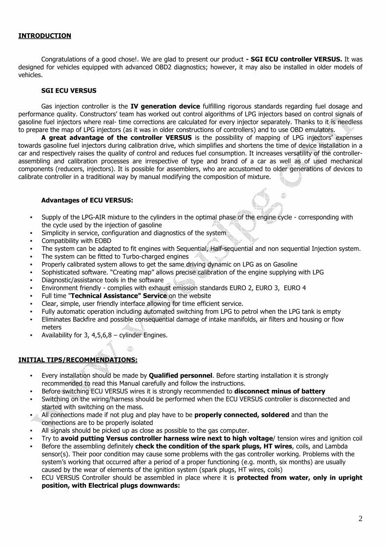
• ECU VERSUS Controller should be assembled in place where it is protected from water, only in upright position, with Electrical plugs downwards:
3
Correct position of fitting Inside drivers cabin In engine chamber (plug downwards)
Incorrect position of fitting (below)
• The controller should be assembled as far as possible
from the sources of high temperature such as cylinder head and exhaust manifold. Guaranteed temperature range of Versus controller work is from -40 to + 125 ºC. If the maximum temperature is exceeded, the controller may switch to petrol in emergency.
• One of the most important while SGI VERSUS installation is Setting up LPG Injector RAIL. General Rules are as follows:
a) The shortest rubber hoses between Injection RAIL and inlet manifold the better b) The hoses has to be the same length. c) The closest to the inlet valves/Gasoline injectors fitting of LPG inlet manifold nozzles the better.
• LPG Injectors inlet manifold nozzles are to be installed VERY carefully. After their installation (drilling) make sure Inlet Manifold is clean from any filings inside. It is strongly recommended to remove the inlet manifold and after drilling the nozzles holes to clean up the manifold inside walls.
• Recommended differential pressure applied on the reducer should be to approx. 100 kPa. While setting up algorithms of the controller the pressure of 100 kPa was taken under consideration.
• Before first switching to gas, the engine should be warmed up on petrol so that the LPG reducer’s heater shows higher temperature than 40 ºC.
• It is recommended to calibrate ECU VERSUS controller in every single car separately. After turning on the engine on petrol, software configuration should be engaged to Versus controller, which should be pre – configured (“Configuration” bookmark)
• With every change of a reducer pressure or injectors’ nozzles, Auto-calibration should be performed again • The latest version of software, diagrams, manuals are available on the website www.versuslpg.com or
www.versuslpg.eu. Technical assistance system is available at www.forum.versuslpg.com. Before starting a new topic READ THIS MANUAL and Existing TOPICS carefully!
4
ECU VERSUS Before installation it is strongly recommended to read carefully tips given above!. ECU VERSUS can be installed:
• In 3,4 cylinders engines – 4-cyl ECU VERSUS Version • In 3,4,5,6 cylinders engines – 6-cyl ECU VERSUS Version • In 3,4,5,6,8 cylinders engines – 8-cyl ECU VERSUS version
It is recommended to install ECU VERSUS with the plugs downwards, in places that protects the ECU from High temperature sources and water. REDUCER ECU VERSUS works properly with different kind of Reducers. The role of the reducer is to evaporate LPG from Liquid phase to gaseous phase by using heat from cooling system. The role of the reducer is to supply LPG Injection RAIL with LPG.
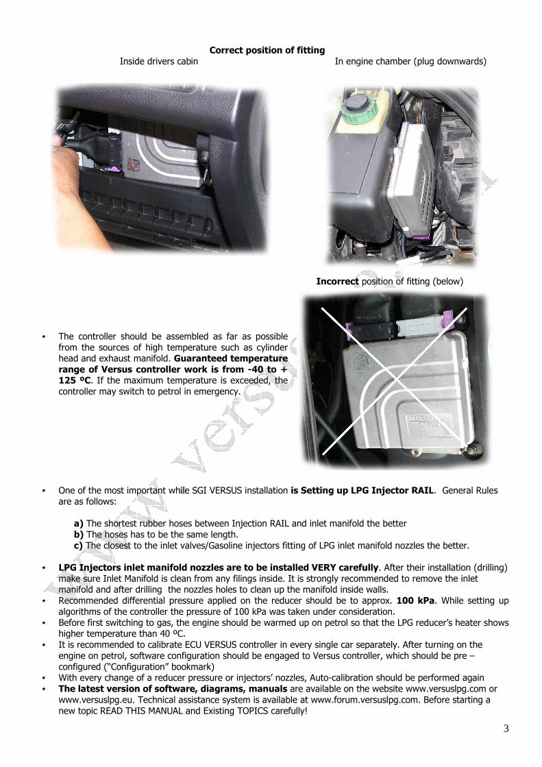
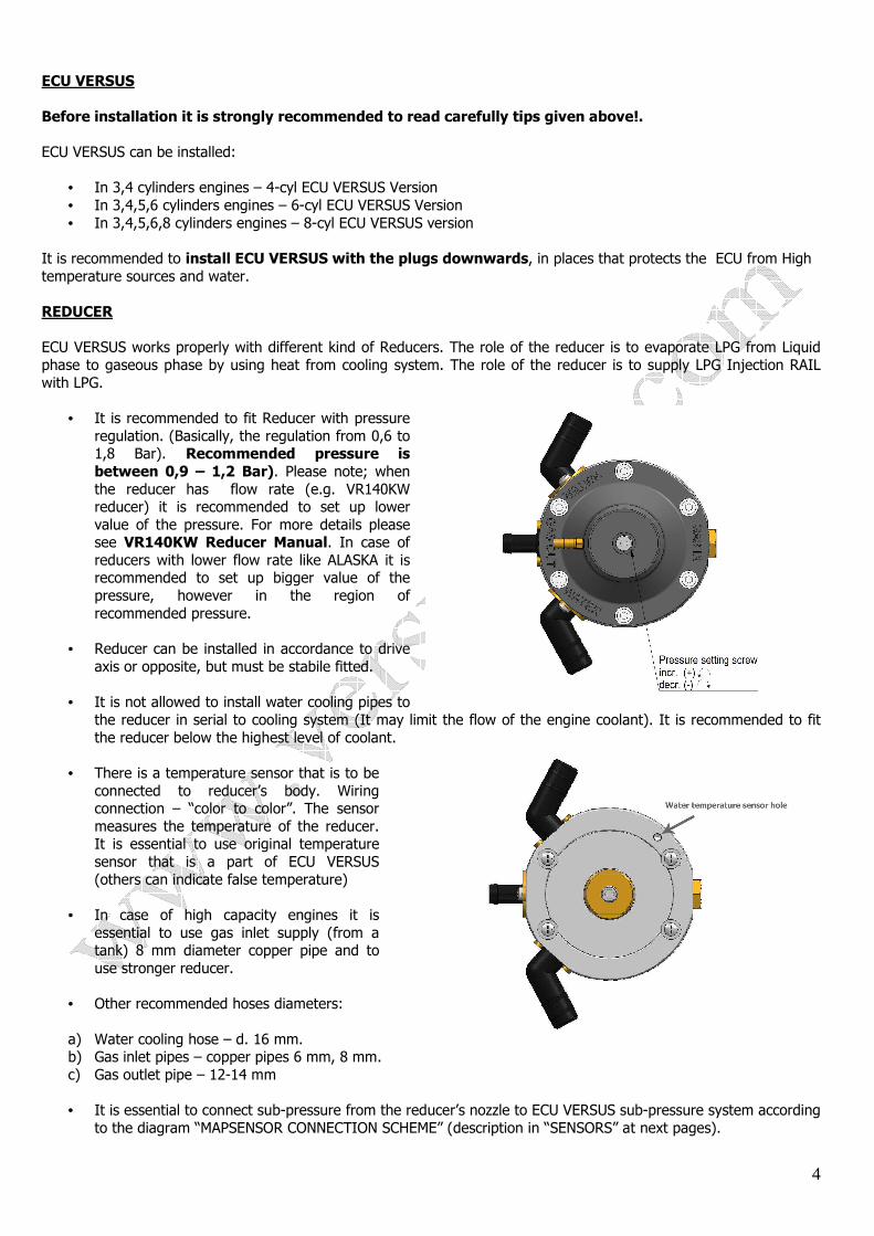
• It is recommended to fit Reducer with pressure regulation. (Basically, the regulation from 0,6 to 1,8 Bar). Recommended pressure is between 0,9 – 1,2 Bar). Please note; when the reducer has flow rate (e.g. VR140KW reducer) it is recommended to set up lower value of the pressure. For more details please see VR140KW Reducer Manual. In case of reducers with lower flow rate like ALASKA it is recommended to set up bigger value of the pressure, however in the region of recommended pressure.
• Reducer can be installed in accordance to drive
axis or opposite, but must be stabile fitted.
• It is not allowed to install water cooling pipes to the reducer in serial to cooling system (It may limit the flow of the engine coolant). It is recommended to fit the reducer below the highest level of coolant.
• There is a temperature sensor that is to be
connected to reducer’s body. Wiring connection – “color to color”. The sensor measures the temperature of the reducer. It is essential to use original temperature sensor that is a part of ECU VERSUS (others can indicate false temperature)
• In case of high capacity engines it is
essential to use gas inlet supply (from a tank) 8 mm diameter copper pipe and to use stronger reducer.
• Other recommended hoses diameters:
a) Water cooling hose – d. 16 mm. b) Gas inlet pipes – copper pipes 6 mm, 8 mm. c) Gas outlet pipe – 12-14 mm
• It is essential to connect sub-pressure from the reducer’s nozzle to ECU VERSUS sub-pressure system according
to the diagram “MAPSENSOR CONNECTION SCHEME” (description in “SENSORS” at next pages).
5
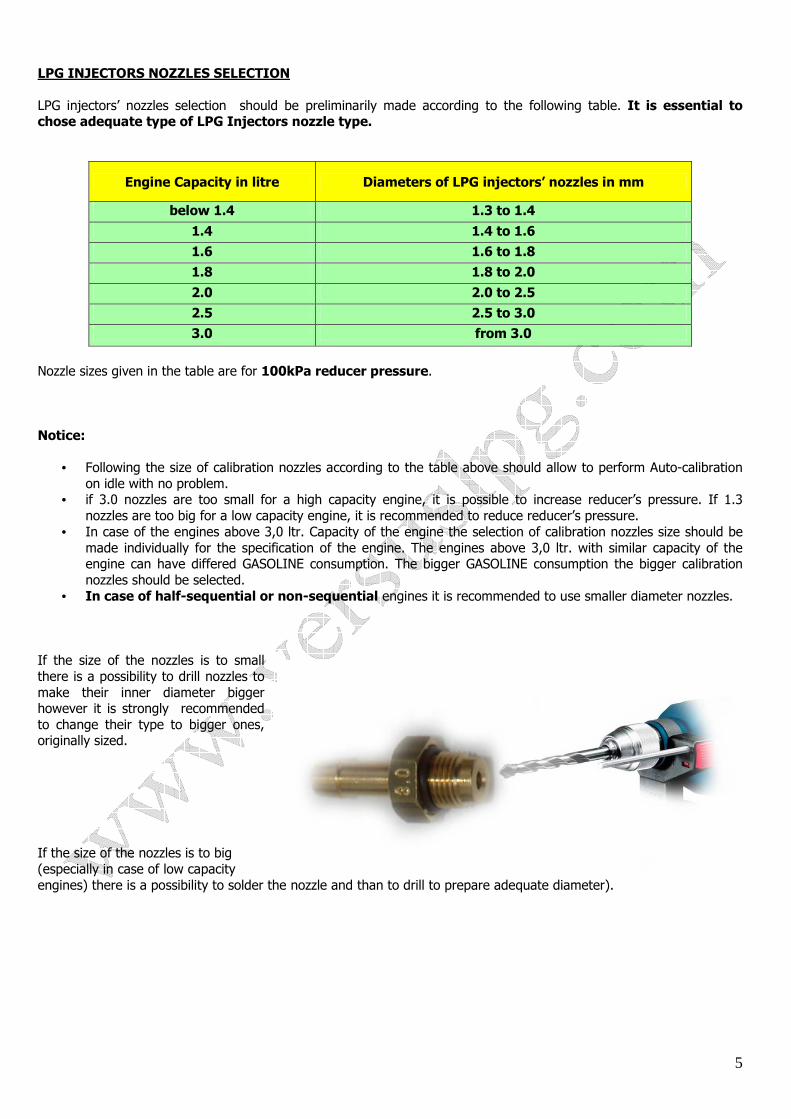
LPG INJECTORS NOZZLES SELECTION LPG injectors’ nozzles selection should be preliminarily made according to the following table. It is essential to chose adequate type of LPG Injectors nozzle type.
Engine Capacity in litre Diameters of LPG injectors’ nozzles in mm
below 1.4 1.3 to 1.4
1.4 1.4 to 1.6
1.6 1.6 to 1.8
1.8 1.8 to 2.0
2.0 2.0 to 2.5
2.5 2.5 to 3.0
3.0 from 3.0
Nozzle sizes given in the table are for 100kPa reducer pressure. Notice:
• Following the size of calibration nozzles according to the table above should allow to perform Auto-calibration on idle with no problem.
• if 3.0 nozzles are too small for a high capacity engine, it is possible to increase reducer’s pressure. If 1.3 nozzles are too big for a low capacity engine, it is recommended to reduce reducer’s pressure.
• In case of the engines above 3,0 ltr. Capacity of the engine the selection of calibration nozzles size should be made individually for the specification of the engine. The engines above 3,0 ltr. with similar capacity of the engine can have differed GASOLINE consumption. The bigger GASOLINE consumption the bigger calibration nozzles should be selected.
• In case of half-sequential or non-sequential engines it is recommended to use smaller diameter nozzles. If the size of the nozzles is to small there is a possibility to drill nozzles to make their inner diameter bigger however it is strongly recommended to change their type to bigger ones, originally sized. If the size of the nozzles is to big (especially in case of low capacity engines) there is a possibility to solder the nozzle and than to drill to prepare adequate diameter).
6
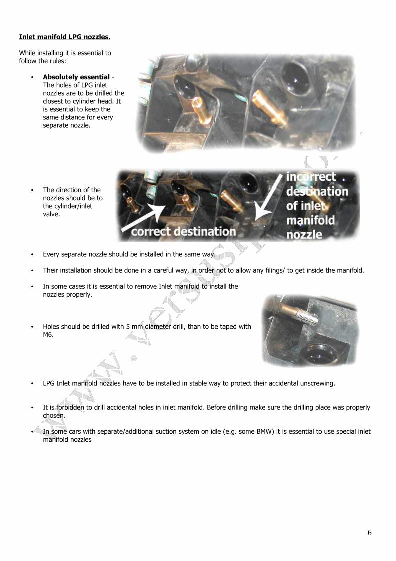
Inlet manifold LPG nozzles. While installing it is essential to follow the rules:
• Absolutely essential - The holes of LPG inlet nozzles are to be drilled the closest to cylinder head. It is essential to keep the same distance for every separate nozzle.
• The direction of the
nozzles should be to the cylinder/inlet valve.
• Every separate nozzle should be installed in the same way. • Their installation should be done in a careful way, in order not to allow any filings/ to get inside the manifold.
• In some cases it is essential to remove Inlet manifold to install the
nozzles properly.
• Holes should be drilled with 5 mm diameter drill, than to be taped with M6.
• LPG Inlet manifold nozzles have to be installed in stable way to protect their accidental unscrewing.
• It is forbidden to drill accidental holes in inlet manifold. Before drilling make sure the drilling place was properly
chosen. • In some cars with separate/additional suction system on idle (e.g. some BMW) it is essential to use special inlet
manifold nozzles
7
LPG INJECTION RAIL ECU VERSUS operates properly with several kinds of LPG Injectors (different Brands, impedance). It is essential to chose the type of installed LPG injectors in the software.
• In case of 4-cyl engine you are to use 1x4 set LPG Injection RAIL. Other possibility - 2x2 set Injection RAIL or 4x1 set LPG Injector.
• In case of 6-cyl engine - 2x3 set LPG injection RAIL. Other possibility 3x2 or 6x1. • 8-cyl engine – 2x4, 4x2, 8x1. • In case of 4-cyl set LPG injectors RAIL and 6-cyl engine only 3 first sections works.
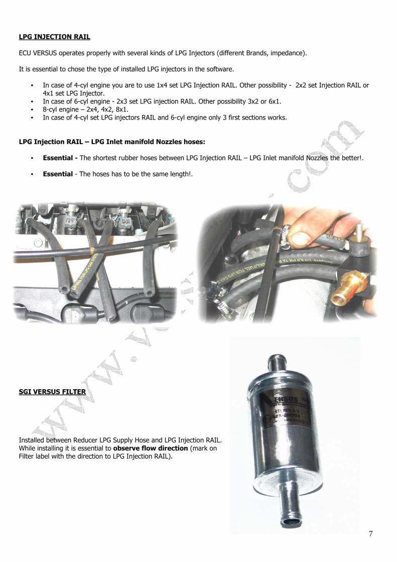
LPG Injection RAIL – LPG Inlet manifold Nozzles hoses:
• Essential - The shortest rubber hoses between LPG Injection RAIL – LPG Inlet manifold Nozzles the better!. • Essential - The hoses has to be the same length!.
SGI VERSUS FILTER Installed between Reducer LPG Supply Hose and LPG Injection RAIL. While installing it is essential to observe flow direction (mark on Filter label with the direction to LPG Injection RAIL).
8
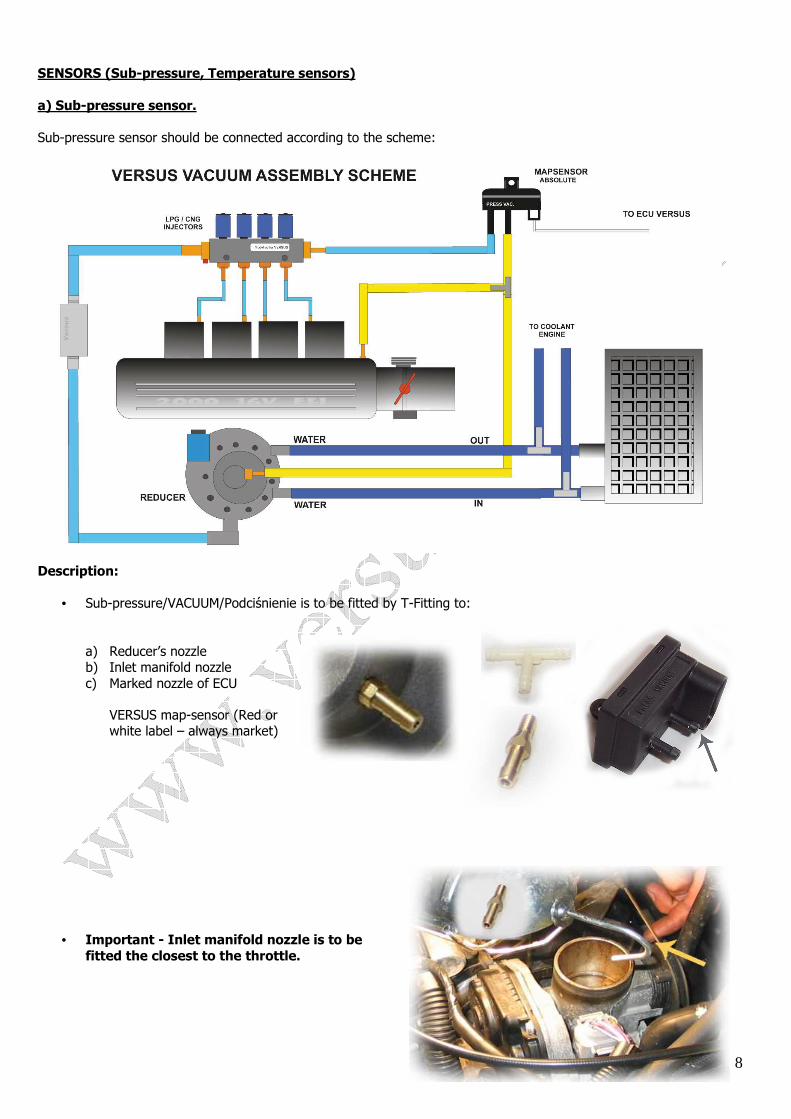
SENSORS (Sub-pressure, Temperature sensors) a) Sub-pressure sensor. Sub-pressure sensor should be connected according to the scheme:
Description:
• Sub-pressure/VACUUM/Podciśnienie is to be fitted by T-Fitting to:
a) Reducer’s nozzle b) Inlet manifold nozzle c) Marked nozzle of ECU
VERSUS map-sensor (Red or white label – always market)
• Important - Inlet manifold nozzle is to be fitted the closest to the throttle.
9
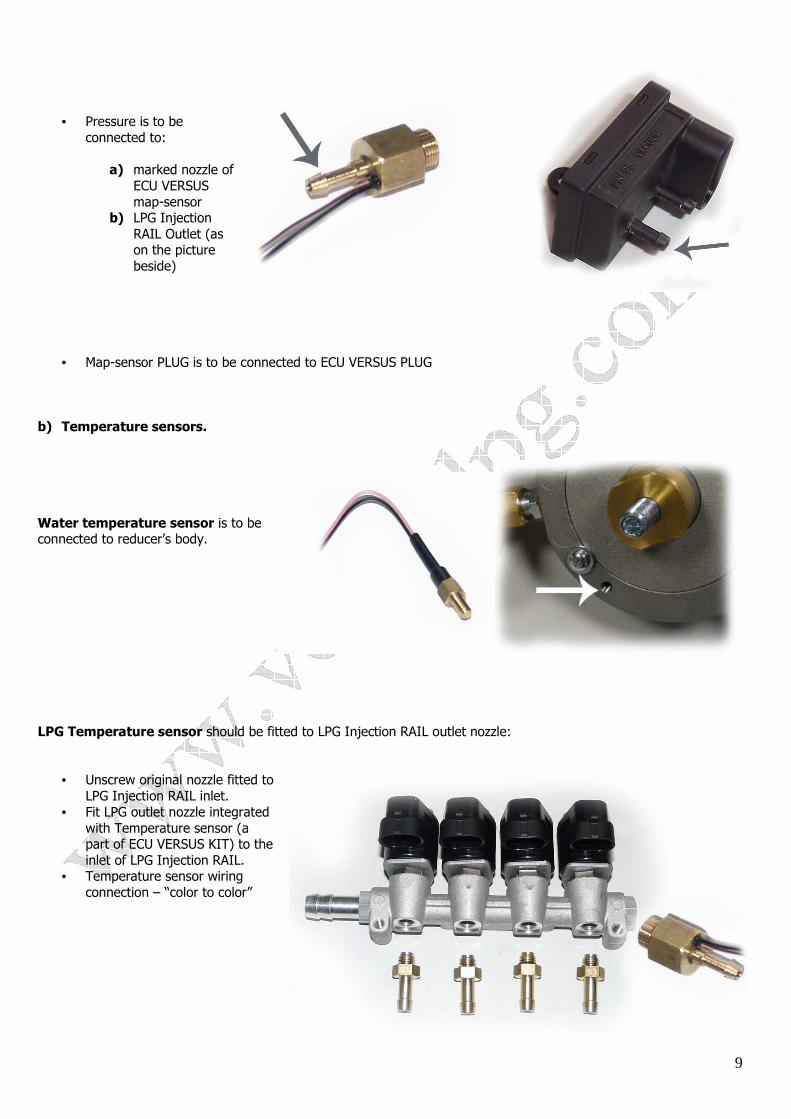
• Pressure is to be
connected to:
a) marked nozzle of ECU VERSUS map-sensor
b) LPG Injection RAIL Outlet (as on the picture beside)
• Map-sensor PLUG is to be connected to ECU VERSUS PLUG b) Temperature sensors. Water temperature sensor is to be connected to reducer’s body. LPG Temperature sensor should be fitted to LPG Injection RAIL outlet nozzle:
• Unscrew original nozzle fitted to LPG Injection RAIL inlet.
• Fit LPG outlet nozzle integrated with Temperature sensor (a part of ECU VERSUS KIT) to the inlet of LPG Injection RAIL.
• Temperature sensor wiring connection – “color to color”
10
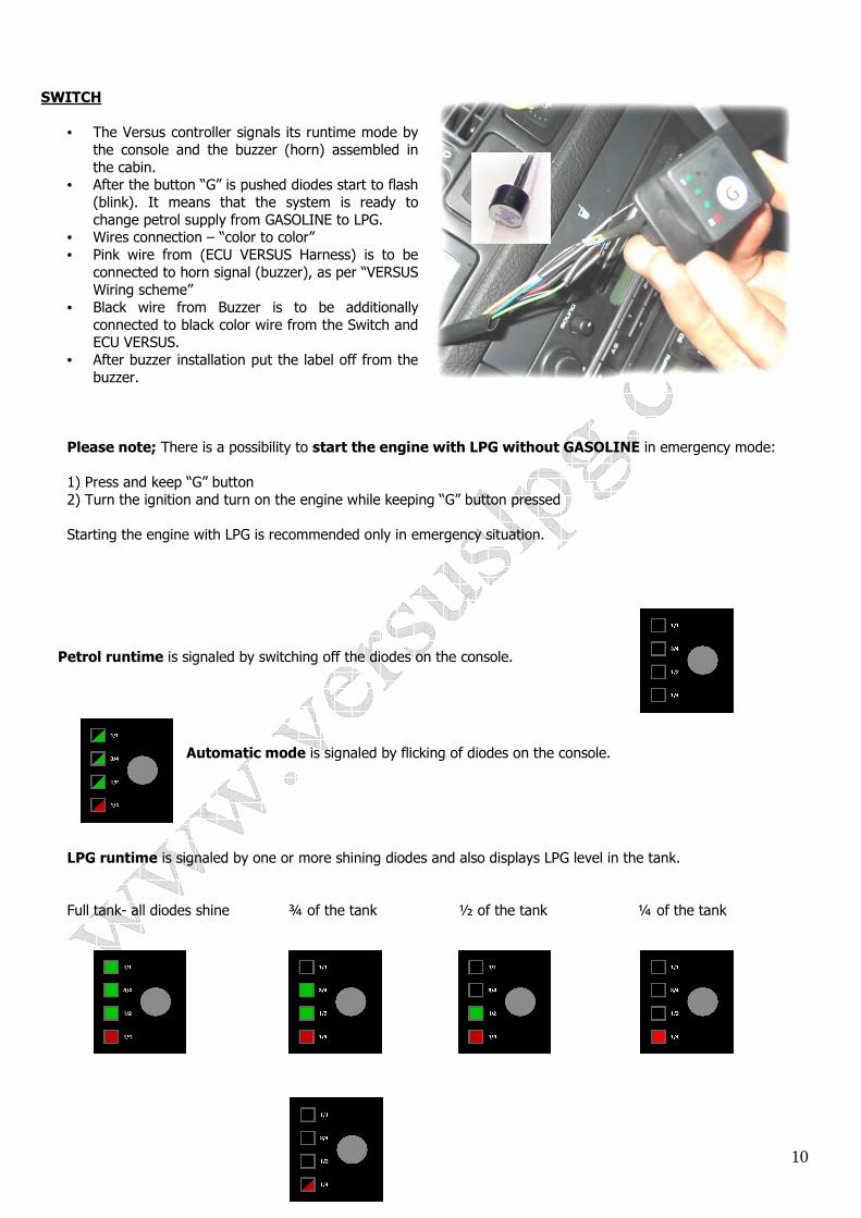
SWITCH
• The Versus controller signals its runtime mode by the console and the buzzer (horn) assembled in the cabin.
• After the button “G” is pushed diodes start to flash (blink). It means that the system is ready to change petrol supply from GASOLINE to LPG.
• Wires connection – “color to color” • Pink wire from (ECU VERSUS Harness) is to be
connected to horn signal (buzzer), as per “VERSUS Wiring scheme”
• Black wire from Buzzer is to be additionally connected to black color wire from the Switch and ECU VERSUS.
• After buzzer installation put the label off from the buzzer.
Please note; There is a possibility to start the engine with LPG without GASOLINE in emergency mode: 1) Press and keep “G” button 2) Turn the ignition and turn on the engine while keeping “G” button pressed Starting the engine with LPG is recommended only in emergency situation.
Petrol runtime is signaled by switching off the diodes on the console.
Automatic mode is signaled by flicking of diodes on the console.
LPG runtime is signaled by one or more shining diodes and also displays LPG level in the tank.
Full tank- all diodes shine ¾ of the tank ½ of the tank ¼ of the tank
11
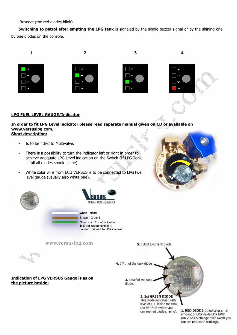
Reserve (the red diodes blink)
Switching to petrol after empting the LPG tank is signaled by the single buzzer signal or by the shining one
by one diodes on the console.
1 2 3 4
LPG FUEL LEVEL GAUGE/Indicator In order to fit LPG Level indicator please read separate manual given on CD or available on www.versuslpg.com. Short description:
• Is to be fitted to Multivalve. • There is a possibility to turn the indicator left or right in order to
achieve adequate LPG Level indication on the Switch (If LPG Tank is full all diodes should shine).
• White color wire from ECU VERSUS is to be connected to LPG Fuel
level gauge (usually also white one).
Indication of LPG VERSUS Gauge is as on the picture beside:
12
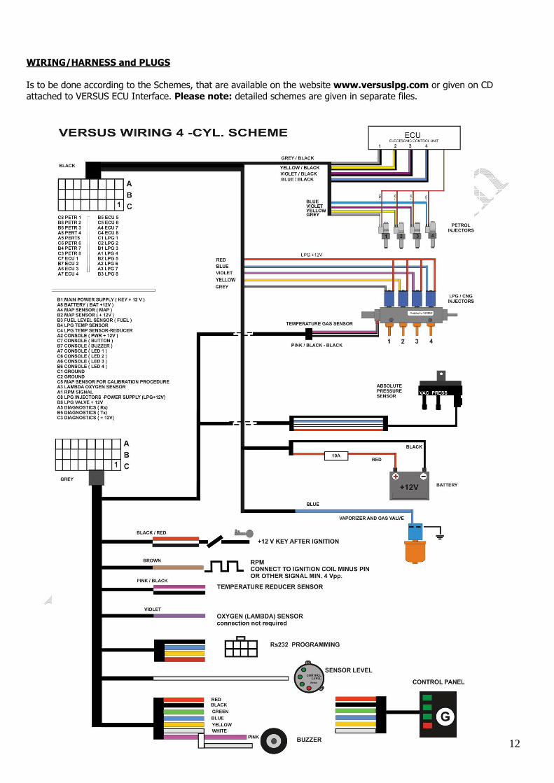
WIRING/HARNESS and PLUGS Is to be done according to the Schemes, that are available on the website www.versuslpg.com or given on CD attached to VERSUS ECU Interface. Please note: detailed schemes are given in separate files.
13
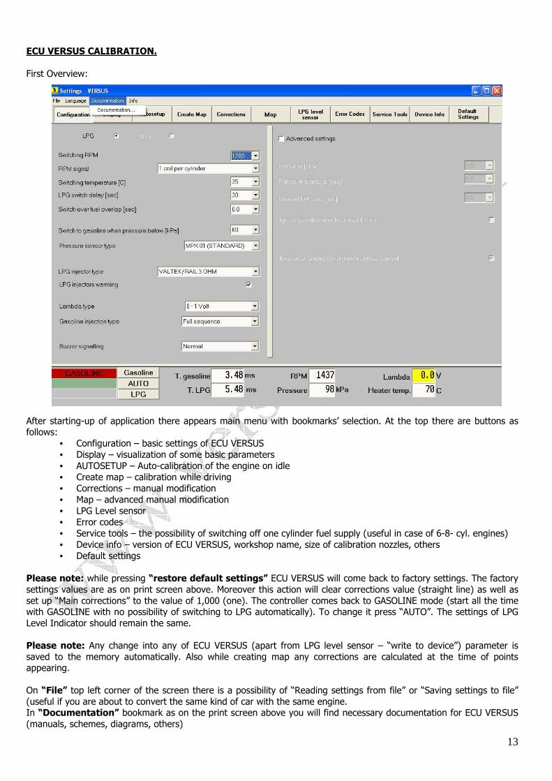
ECU VERSUS CALIBRATION. First Overview: After starting-up of application there appears main menu with bookmarks’ selection. At the top there are buttons as follows:
• Configuration – basic settings of ECU VERSUS • Display – visualization of some basic parameters • AUTOSETUP – Auto-calibration of the engine on idle • Create map – calibration while driving • Corrections – manual modification • Map – advanced manual modification • LPG Level sensor • Error codes • Service tools – the possibility of switching off one cylinder fuel supply (useful in case of 6-8- cyl. engines) • Device info – version of ECU VERSUS, workshop name, size of calibration nozzles, others • Default settings
Please note: while pressing “restore default settings” ECU VERSUS will come back to factory settings. The factory settings values are as on print screen above. Moreover this action will clear corrections value (straight line) as well as set up “Main corrections” to the value of 1,000 (one). The controller comes back to GASOLINE mode (start all the time with GASOLINE with no possibility of switching to LPG automatically). To change it press “AUTO”. The settings of LPG Level Indicator should remain the same. Please note: Any change into any of ECU VERSUS (apart from LPG level sensor – “write to device”) parameter is saved to the memory automatically. Also while creating map any corrections are calculated at the time of points appearing. On “File” top left corner of the screen there is a possibility of “Reading settings from file” or “Saving settings to file” (useful if you are about to convert the same kind of car with the same engine. In “Documentation” bookmark as on the print screen above you will find necessary documentation for ECU VERSUS (manuals, schemes, diagrams, others)
14
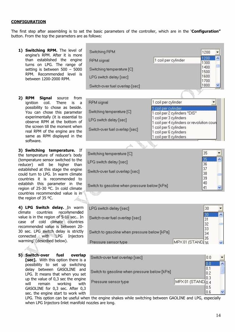
CONFIGURATION The first step after assembling is to set the basic parameters of the controller, which are in the ‘Configuration” button. From the top the parameters are as follows:
1) Switching RPM. The level of engine’s RPM. After it is more than established the engine turns on LPG. The range of setting is between 500 – 5000 RPM. Recommended level is between 1200-2000 RPM.
2) RPM Signal source from ignition coil. There is a possibility to chose as beside. You can chose this parameter experimentally (it is essential to observe RPM at the bottom of the screen till the moment when real RPM of the engine are the same as RPM displayed in the software.
3) Switching temperature. If the temperature of reducer’s body (temperature sensor switched to the reducer) will be higher than established at this stage the engine could turn to LPG. In warm climate countries it is recommended to establish this parameter in the region of 25-30 ºC. In cold climate countries recommended value is in the region of 35 ºC. 4) LPG Switch delay. In warm climate countries recommended value is in the region of 5-10 sec.. In case of cold climate countries recommended value is between 20-30 sec. LPG switch delay is strictly connected with ‘LPG Injectors warming’ (described below).
5) Switch-over fuel overlap [sec]. With this option there is a possibility to set up switching delay between GASOLINE and LPG. It means that when you set up the value of 0,3 sec the engine will remain working with GASOLINE for 0,3 sec. After 0,3 sec. the engine start to work with LPG. This option can be useful when the engine shakes while switching between GAOLINE and LPG, especially when LPG Injectors-Inlet manifold nozzles are long.
15
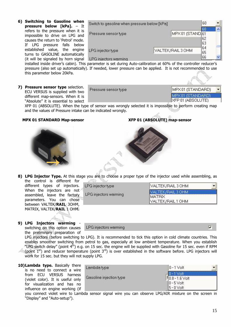
6) Switching to Gasoline when pressure below [kPa]. – It refers to the pressure when it is impossible to drive on LPG and causes the return to ‘Petrol’ mode. If LPG pressure falls below established value, the engine turns to GASOLINE automatically (it will be signaled by horn signal installed inside driver’s cabin). This parameter is set during Auto-calibration at 60% of the controller reducer’s pressure (also set up automatically). If needed, lower pressure can be applied. It is not recommended to use this parameter below 20kPa.
7) Pressure sensor type selection. ECU VERSUS is supplied with two different map-sensors. When it is “Absolute” it is essential to select XFP 01 (ABSOLUTE). When the type of sensor was wrongly selected it is impossible to perform creating map and the values of Pressure intake can be indicated wrongly.
MPX 01 STANDARD Map-sensor XFP 01 (ABSOLUTE) map-sensor
8) LPG Injector Type. At this stage you are to choose a proper type of the injector used while assembling, as
the control is different for different types of injectors. When the injectors are not assembled, leave the factory parameters. You can chose between VALTEK/RAIL 3OHM, MATRIX, VALTEK/RAIL 1 OHM.
9) LPG Injectors warming -
switching on this option causes the preliminary preparation of LPG injectors (before switching to LPG). It is recommended to tick this option in cold climate countries. This enables smoother switching from petrol to gas, especially at low ambient temperature. When you establish “LPG switch delay” (point 4th) e.g. on 15 sec. the engine will be supplied with Gasoline for 15 sec. even if RPM (point 1st) and reducer temperature (point 3rd) is over established in the software before. LPG injectors will work for 15 sec. but they will not supply LPG.
10) Lambda type. Basically there
is no need to connect a wire from ECU VERSUS harness (violet color). It is useful only for visualization and has no influence on engine working (if you connect violet wire to Lambda sensor signal wire you can observe LPG/AIR mixture on the screen in “Display” and “Auto-setup”).
16
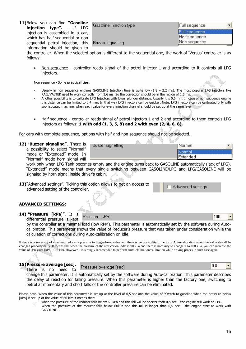
11) Below you can find “Gasoline injection type”. - if LPG injection is assembled in a car, which has half-sequential or non sequential petrol injection, this information should be given to the controller. When the selected option is different to the sequential one, the work of ‘Versus’ controller is as follows:
•••• Non sequence - controller reads signal of the petrol injector 1 and according to it controls all LPG
injectors. Non sequence - Some practical tips: - Usually in non sequence engines GASOLINE Injection time is quite low (1,8 – 2,2 ms). The most popular LPG injectors like
RAIL/VALTEK used to work correctly from 3,6 ms. So the correction should be in the region of 1,5 ms. - Another possibility is to calibrate LPG Injectors with lower plunger distance. Usually it is 0,6 mm. In case of non sequence engine
this distance can be limited to 0,4 mm. In that way LPG injectors can be quicker. Note; LPG injectors can be calibrated only with sophisticated machine, when each value for every injection channel should be set up at the same level.
•••• Half sequence - controller reads signal of petrol injectors 1 and 2 and according to them controls LPG injectors as follows: 1 with odd (1, 3, 5, 8) and 2 with even (2, 4, 6, 8).
For cars with complete sequence, options with half and non sequence should not be selected.
12) “Buzzer signaling”. There is
a possibility to select “Normal” mode or “Extended” mode. In “Normal” mode horn signal will work only when LPG Tank becomes empty and the engine turns back to GASOLINE automatically (lack of LPG). “Extended” mode means that every single switching between GASOLINE/LPG and LPG/GASOLINE will be signaled by horn signal inside driver’s cabin.
13) “Advanced settings”. Ticking this option allows to get an access to
advanced setting of the controller. ADVANCED SETTINGS: 14) “Pressure [kPa]”. It is
differential pressure is kept by the controller at a minimal load (low RPM). This parameter is automatically set by the software during Auto-calibration. This parameter shows the value of Reducer’s pressure that was taken under consideration while the calculation of corrections during Auto-calibration on idle.
If there is a necessity of changing reducer’s pressure to bigger/lover value and there is no possibility to perform Auto-calibration again the value shoudl be changed proportionally. It means that when the pressure of the reducer on iddle is 90 kPa and there is necessity to change it to 100 kPa, you can increase the value of „Pressure [kPa] + 10 kPa. Hovewer it is strongly recomended to perform Auto-claibration/calibration while driving proces in such case again.
15) Pressure average [sec].
There is no need to change this parameter. It is automatically set by the software during Auto-calibration. This parameter describes the delay of reaction for falling pressure. When this parameter is higher than the factory one, switching to petrol at momentary and short falls of the controller pressure can be eliminated.
Please note. When the value of this parameter is set up at the level of 0,5 sec and the value of “Switch to gasoline when the pressure below [kPa] is set up at the value of 60 kPa it means that:
- when the pressure of the reducer falls below 60 kPa and this fall will be shorter than 0,5 sec – the engine still work on LPG. - When the pressure of the reducer falls below 60kPa and this fall is longer than 0,5 sec – the engine start to work with
GASOLINE.
17
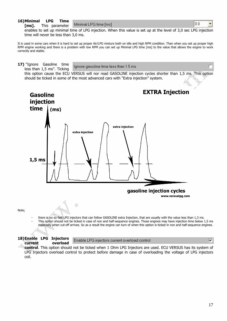
16) Minimal LPG Time [ms]. This parameter enables to set up minimal time of LPG injection. When this value is set up at the level of 3,0 sec LPG injection time will never be less than 3,0 ms.
It is used in some cars when it is hard to set up proper Air/LPG mixture both on idle and high RPM condition. Than when you set up proper high RPM engine working and there is a problem with low RPM you can set up Minimal LPG time [ms] to the value that allows the engine to work correctly and stable.
17) “Ignore Gasoline time
less than 1,5 ms”. Ticking this option cause the ECU VERSUS will nor read GASOLINE injection cycles shorter than 1,5 ms. This option should be ticked in some of the most advanced cars with “Extra injection” system.
Note;
- there is no so fast LPG injectors that can follow GASOLINE extra Injection, that are usually with the value less than 1,3 ms. - This option should not be ticked in case of non and half-sequence engines. Those engines may have injection time below 1,5 ms
especially when cut-off arrives. So as a result the engine can turn of when this option is ticked in non and half-sequence engines.
18) Enable LPG Injectors current overload control. This option should not be ticked when 1 Ohm LPG Injectors are used. ECU VERSUS has its system of LPG Injectors overload control to protect before damage in case of overloading the voltage of LPG injectors coil.
18
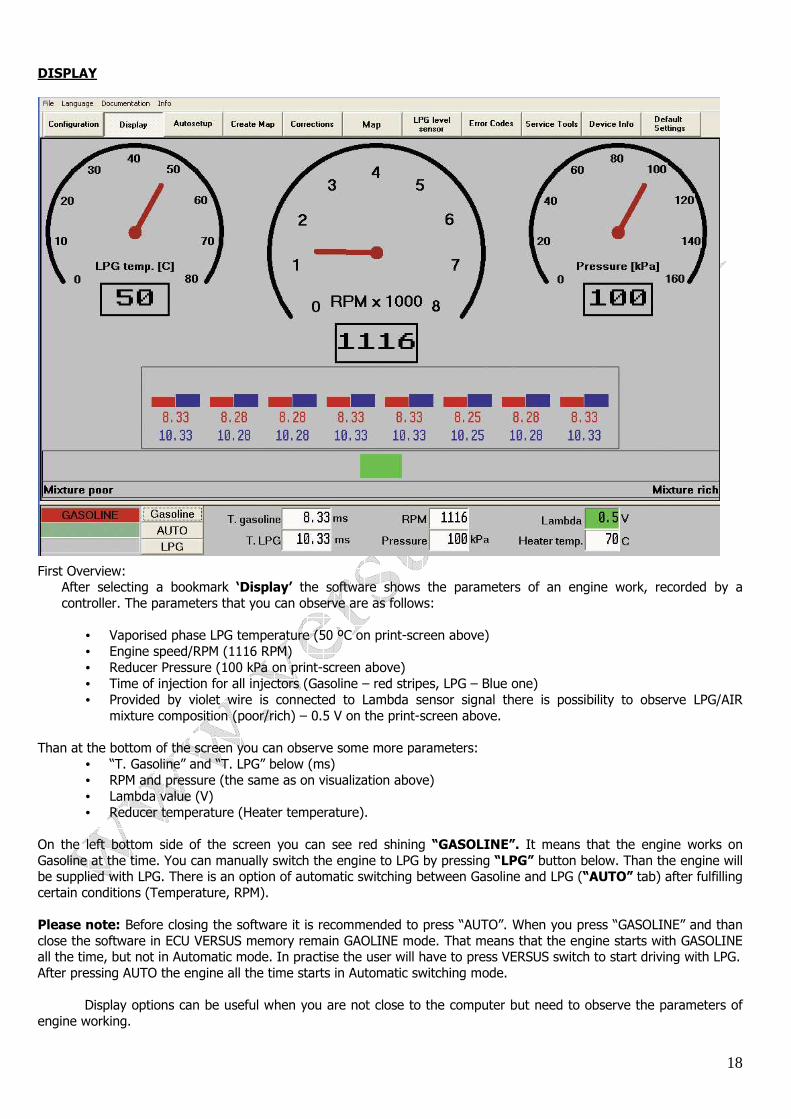
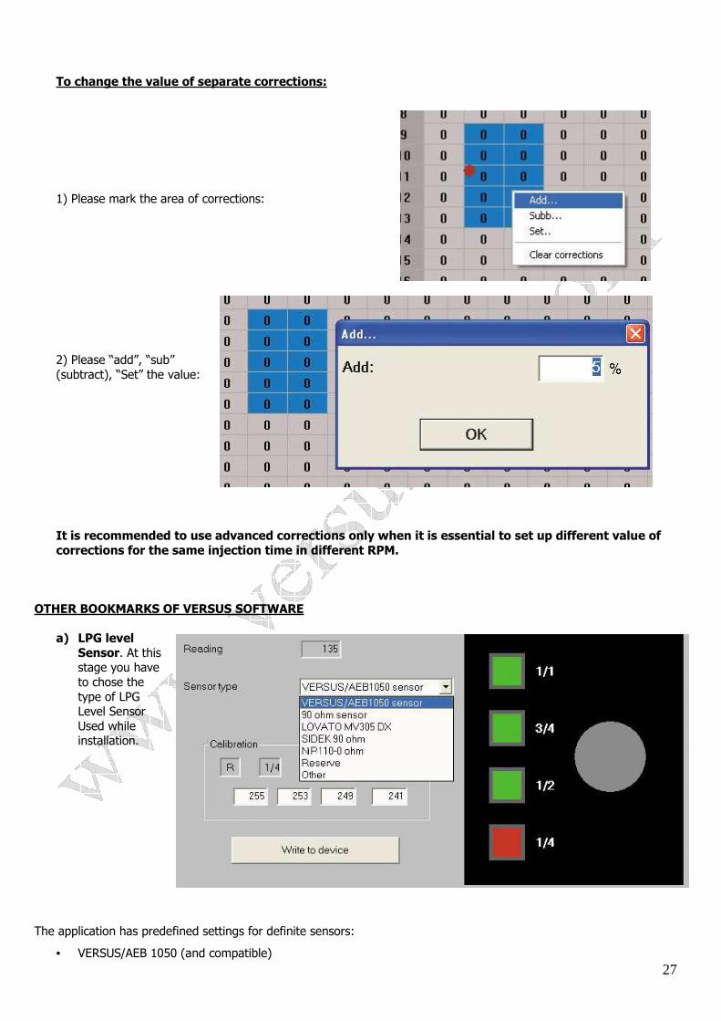
DISPLAY
First Overview: After selecting a bookmark ‘Display’ the software shows the parameters of an engine work, recorded by a controller. The parameters that you can observe are as follows:
• Vaporised phase LPG temperature (50 ºC on print-screen above) • Engine speed/RPM (1116 RPM) • Reducer Pressure (100 kPa on print-screen above) • Time of injection for all injectors (Gasoline – red stripes, LPG – Blue one) • Provided by violet wire is connected to Lambda sensor signal there is possibility to observe LPG/AIR
mixture composition (poor/rich) – 0.5 V on the print-screen above. Than at the bottom of the screen you can observe some more parameters:
• “T. Gasoline” and “T. LPG” below (ms) • RPM and pressure (the same as on visualization above) • Lambda value (V) • Reducer temperature (Heater temperature).
On the left bottom side of the screen you can see red shining “GASOLINE”. It means that the engine works on Gasoline at the time. You can manually switch the engine to LPG by pressing “LPG” button below. Than the engine will be supplied with LPG. There is an option of automatic switching between Gasoline and LPG (“AUTO” tab) after fulfilling certain conditions (Temperature, RPM). Please note: Before closing the software it is recommended to press “AUTO”. When you press “GASOLINE” and than close the software in ECU VERSUS memory remain GAOLINE mode. That means that the engine starts with GASOLINE all the time, but not in Automatic mode. In practise the user will have to press VERSUS switch to start driving with LPG. After pressing AUTO the engine all the time starts in Automatic switching mode.
Display options can be useful when you are not close to the computer but need to observe the parameters of engine working.
19
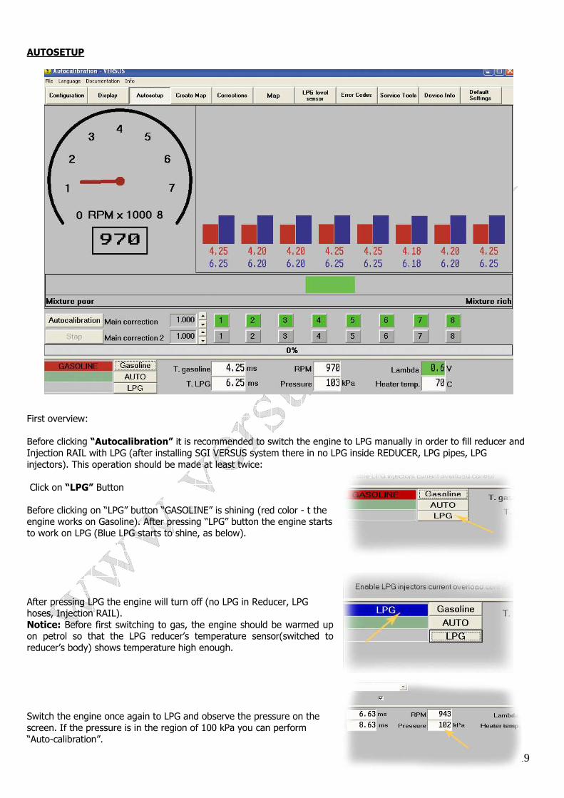
AUTOSETUP
First overview: Before clicking “Autocalibration” it is recommended to switch the engine to LPG manually in order to fill reducer and Injection RAIL with LPG (after installing SGI VERSUS system there in no LPG inside REDUCER, LPG pipes, LPG injectors). This operation should be made at least twice: Click on “LPG” Button Before clicking on “LPG” button “GASOLINE” is shining (red color - t the engine works on Gasoline). After pressing “LPG” button the engine starts to work on LPG (Blue LPG starts to shine, as below). After pressing LPG the engine will turn off (no LPG in Reducer, LPG hoses, Injection RAIL). Notice: Before first switching to gas, the engine should be warmed up on petrol so that the LPG reducer’s temperature sensor(switched to reducer’s body) shows temperature high enough. Switch the engine once again to LPG and observe the pressure on the screen. If the pressure is in the region of 100 kPa you can perform “Auto-calibration”.
20
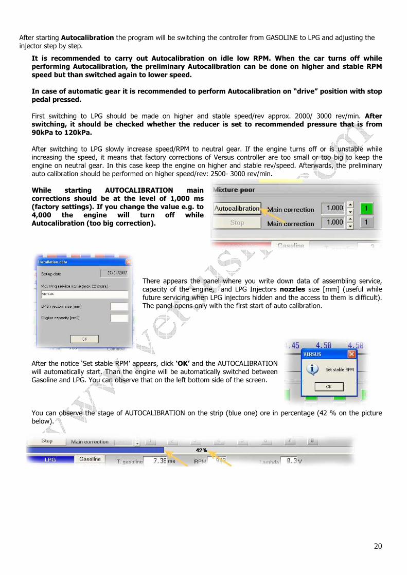
After starting Autocalibration the program will be switching the controller from GASOLINE to LPG and adjusting the injector step by step.
It is recommended to carry out Autocalibration on idle low RPM. When the car turns off while performing Autocalibration, the preliminary Autocalibration can be done on higher and stable RPM speed but than switched again to lower speed. In case of automatic gear it is recommended to perform Autocalibration on “drive” position with stop pedal pressed. First switching to LPG should be made on higher and stable speed/rev approx. 2000/ 3000 rev/min. After switching, it should be checked whether the reducer is set to recommended pressure that is from 90kPa to 120kPa.
After switching to LPG slowly increase speed/RPM to neutral gear. If the engine turns off or is unstable while increasing the speed, it means that factory corrections of Versus controller are too small or too big to keep the engine on neutral gear. In this case keep the engine on higher and stable rev/speed. Afterwards, the preliminary auto calibration should be performed on higher speed/rev: 2500- 3000 rev/min. While starting AUTOCALIBRATION main corrections should be at the level of 1,000 ms (factory settings). If you change the value e.g. to 4,000 the engine will turn off while Autocalibration (too big correction).
There appears the panel where you write down data of assembling service, capacity of the engine, and LPG Injectors nozzles size [mm] (useful while future servicing when LPG injectors hidden and the access to them is difficult). The panel opens only with the first start of auto calibration.
After the notice ‘Set stable RPM’ appears, click ‘OK’ and the AUTOCALIBRATION will automatically start. Than the engine will be automatically switched between Gasoline and LPG. You can observe that on the left bottom side of the screen.
You can observe the stage of AUTOCALIBRATION on the strip (blue one) ore in percentage (42 % on the picture below).
21
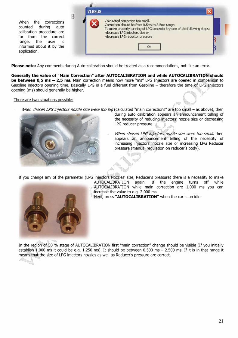
When the corrections counted during auto calibration procedure are far from the correct range, the user is informed about it by the application.
Please note: Any comments during Auto-calibration should be treated as a recommendations, not like an error. Generally the value of “Main Correction” after AUTOCALIBRATION and while AUTOCALIBRATION should be between 0,5 ms – 2,5 ms. Main correction means how more “ms” LPG Injectors are opened in comparison to Gasoline injectors opening time. Basically LPG is a fuel different from Gasoline – therefore the time of LPG Injectors opening (ms) should generally be higher. There are two situations possible:
- When chosen LPG injectors nozzle size were too big (calculated “main corrections” are too small – as above), then during auto calibration appears an announcement telling of the necessity of reducing injectors’ nozzle size or decreasing LPG reducer pressure.
- When chosen LPG injectors nozzle size were too small, then
appears an announcement telling of the necessity of increasing injectors’ nozzle size or increasing LPG Reducer pressure (manual regulation on reducer’s body).
If you change any of the parameter (LPG injectors Nozzles’ size, Reducer’s pressure) there is a necessity to make
AUTOCALIBRATION again. If the engine turns off while AUTOCALIBRATION while main correction are 1,000 ms you can increase the value to e.g. 2.000 ms. Next, press “AUTOCALIBRATION” when the car is on idle.
In the region of 50 % stage of AUTOCALIBRATION first “main correction” change should be visible (If you initially establish 1,000 ms it could be e.g. 1.250 ms). It should be between 0.500 ms – 2.500 ms. If it is in that range it means that the size of LPG injectors nozzles as well as Reducer’s pressure are correct.

22
Two different “Main corrections”.
There are two different corrections, useful especially in case of two head engines. E.g. if there is 8-cyl engine one side of the engine works better (pressure on the cylinders is better) there is a possibility to press “5”, “6”, “7”, “8” buttons and change the value of second main correction. Other words; you are to observe in the software screen the difference between Gasoline injection time and LPG Injectors time. Than if the value for the cylinders 1-4 is different than for the cylinders 5-8 you can change first or second correction to make proper correction for the second side of the engine. It is to be done manually.
If everything is correct the system does not display any Error Codes. And the engine switch from Gasoline to LPG with no shaking. The engine will switch to LPG with no shaking provided by:
• The sizes of LPG injectors’ nozzle size are correct • Reducer pressure is correct • Main correction are between 0.500 ms – 2.500 ms
Notice: AUTOCALIBRATION does not guarantee a proper running of the engine supplied with LPG in whole range of engine’s loading. It is strongly recommended to go to “Create map” and to make Calibration while driving, especially in EURO 4 norm cars.
CREATE MAP First overview:
23
Please note: In case of STANDARD map-sensor in order to “Create map” you have to switch additional Calibration map-sensor according to the scheme given in another file:
• Calibration map-sensor is to be connected only to “Subpressure” / ”Vacuum” / ”Podciśnienie”. • Plug with Blue, Red and Black wires is to be connected to Calibration Map-sensor. • Plug with White, Red and Black wires is to be connected to ECU VERSUS map-sensor. • If Calibration map-sensor is properly connected ‘Pressure Intake” is shown in the software
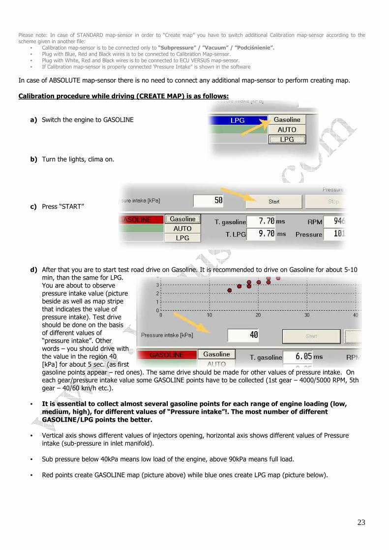
In case of ABSOLUTE map-sensor there is no need to connect any additional map-sensor to perform creating map. Calibration procedure while driving (CREATE MAP) is as follows:
a) Switch the engine to GASOLINE
b) Turn the lights, clima on.
c) Press “START”
d) After that you are to start test road drive on Gasoline. It is recommended to drive on Gasoline for about 5-10 min, than the same for LPG. You are about to observe pressure intake value (picture beside as well as map stripe that indicates the value of pressure intake). Test drive should be done on the basis of different values of “pressure intake”. Other words – you should drive with the value in the region 40 [kPa] for about 5 sec. (as first gasoline points appear – red ones). The same drive should be made for other values of pressure intake. On each gear/pressure intake value some GASOLINE points have to be collected (1st gear – 4000/5000 RPM, 5th gear – 40/60 km/h etc.).
• It is essential to collect almost several gasoline points for each range of engine loading (low, medium, high), for different values of “Pressure intake”!. The most number of different GASOLINE/LPG points the better.
• Vertical axis shows different values of injectors opening, horizontal axis shows different values of Pressure
intake (sub-pressure in inlet manifold). • Sub pressure below 40kPa means low load of the engine, above 90kPa means full load.
• Red points create GASOLINE map (picture above) while blue ones create LPG map (picture below).
24
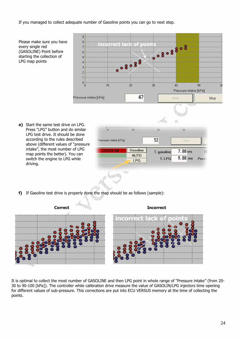
If you managed to collect adequate number of Gasoline points you can go to next step. Please make sure you have every single red (GASOLINE) Point before starting the collection of LPG map points
e) Start the same test drive on LPG.
Press “LPG” button and do similar LPG test drive. It should be done according to the rules described above (different values of “pressure intake”, the most number of LPG map points the better). You can switch the engine to LPG while driving.
f) If Gasoline test drive is properly done the map should be as follows (sample):
Correct Incorrect
It is optimal to collect the most number of GASOLINE and then LPG point in whole range of “Pressure intake” (from 20-30 to 90-100 [kPa]). The controller while calibration drive measure the value of GASOLIN/LPG injectors time opening for different values of sub-pressure. This corrections are put into ECU VERSUS memory at the time of collecting the points.
25
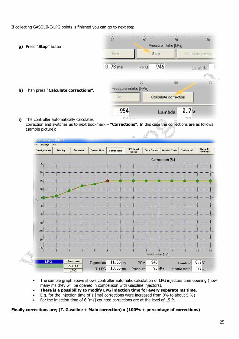
If collecting GASOLINE/LPG points is finished you can go to next step.
g) Press “Stop” button.
h) Than press “Calculate corrections”.
i) The controller automatically calculates correction and switches us to next bookmark – “Corrections”. In this case the corrections are as follows (sample picture):
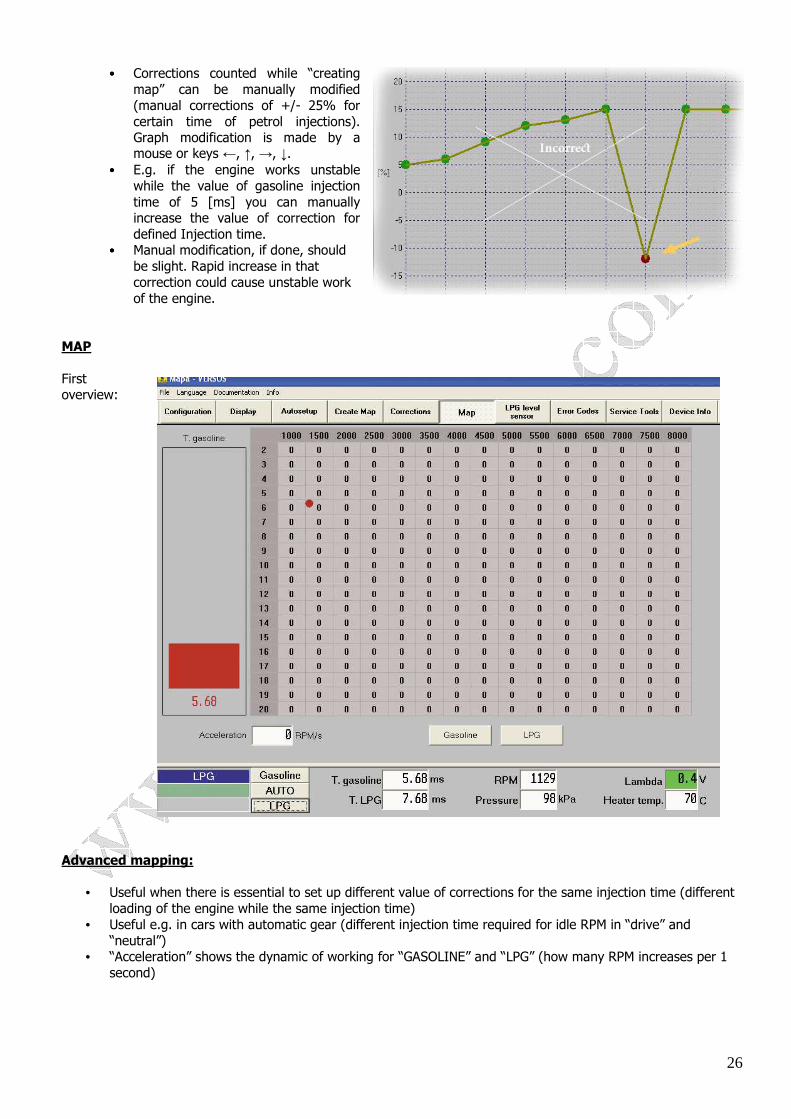
•••• The sample graph above shows controller automatic calculation of LPG injectors time opening (how many ms they will be opened in comparison with Gasoline injectors).
•••• There is a possibility to modify LPG injection time for every separate ms time. •••• E.g. for the injection time of 1 [ms] corrections were increased from 0% to about 5 %) •••• For the injection time of 6 [ms] counted corrections are at the level of 15 %.
Finally corrections are; (T. Gasoline + Main correction) x (100% + percentage of corrections)
26
•••• Corrections counted while “creating map” can be manually modified (manual corrections of +/- 25% for certain time of petrol injections). Graph modification is made by a mouse or keys ←, ↑, →, ↓.
•••• E.g. if the engine works unstable while the value of gasoline injection time of 5 [ms] you can manually increase the value of correction for defined Injection time.
•••• Manual modification, if done, should be slight. Rapid increase in that correction could cause unstable work of the engine.
MAP First overview: Advanced mapping:
• Useful when there is essential to set up different value of corrections for the same injection time (different loading of the engine while the same injection time)
• Useful e.g. in cars with automatic gear (different injection time required for idle RPM in “drive” and “neutral”)
• “Acceleration” shows the dynamic of working for “GASOLINE” and “LPG” (how many RPM increases per 1 second)
27
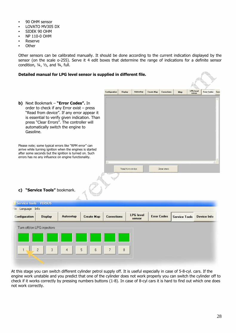
To change the value of separate corrections: 1) Please mark the area of corrections: 2) Please “add”, “sub” (subtract), “Set” the value: It is recommended to use advanced corrections only when it is essential to set up different value of corrections for the same injection time in different RPM.
OTHER BOOKMARKS OF VERSUS SOFTWARE
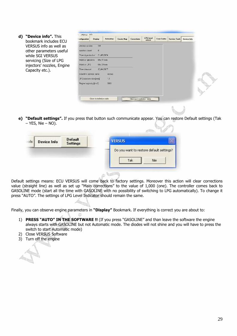
a) LPG level Sensor. At this stage you have to chose the type of LPG Level Sensor Used while installation.
The application has predefined settings for definite sensors:
• VERSUS/AEB 1050 (and compatible)
28
• 90 OHM sensor • LOVATO MV305 DX • SIDEK 90 OHM • NP 110-0 OHM • Reserve • Other
Other sensors can be calibrated manually. It should be done according to the current indication displayed by the sensor (on the scale o-255). Serve it 4 edit boxes that determine the range of indications for a definite sensor condition, ¼, ½, and ¾, full. Detailed manual for LPG level sensor is supplied in different file.
b) Next Bookmark – “Error Codes”. In
order to check if any Error exist – press “Read from device”. If any error appear it is essential to verify given indication. Than press “Clear Errors”. The controller will automatically switch the engine to Gasoline.
Please note; some typical errors like “RPM error” can arrive while turning ignition when the engines is started after some seconds but the ignition is turned on. Such errors has no any influence on engine functionality.
c) “Service Tools” bookmark.
At this stage you can switch different cylinder petrol supply off. It is useful especially in case of 5-8-cyl. cars. If the engine work unstable and you predict that one of the cylinder does not work properly you can switch the cylinder off to check if it works correctly by pressing numbers buttons (1-8). In case of 8-cyl cars it is hard to find out which one does not work correctly.
29
d) “Device info”. This bookmark includes ECU VERSUS info as well as other parameters useful while SGI VERSUS servicing (Size of LPG injectors’ nozzles, Engine Capacity etc.).
e) “Default settings”. If you press that button such communicate appear. You can restore Default settings (Tak – YES, Nie – NO).
Default settings means: ECU VERSUS will come back to factory settings. Moreover this action will clear corrections value (straight line) as well as set up “Main corrections” to the value of 1,000 (one). The controller comes back to GASOLINE mode (start all the time with GASOLINE with no possibility of switching to LPG automatically). To change it press “AUTO”. The settings of LPG Level Indicator should remain the same. Finally, you can observe engine parameters in “Display” Bookmark. If everything is correct you are about to:
1) PRESS “AUTO” IN THE SOFTWARE !! (If you press “GASOLINE” and than leave the software the engine always starts with GASOLINE but not Automatic mode. The diodes will not shine and you will have to press the switch to start Automatic mode)
2) Close VERSUS Software 3) Turn off the engine
30
TYPICAL PROBLEMS/SOLUTIONS:
• There is no possibility to switch the engine to LPG. Possible mistakes:
- wrongly connected RPM wire - RPM signal used to miss after some seconds (in that case it is essential to find another source of RPM – diagnostic
plug or Desk board indication wire) - wrongly set up value of RPM source (e.g. indication of 4000 RPM on idle) - no LPG pressure - Engine to cold or to much air inside water cooling system. - Wrongly connected Temperature sensors or no indication form temperature sensors - Not original temperature sensors used - broken coil on Multivalve or LPG solenoid - Lack of LPG inside the tank - Wrongly selected type of map-sensor (wrong indication in the software)
• The engine starts with GASOLINE and do not switch to LPG automatically.
- before closing the software please click “AUTO” (left bottom corner of the screen software) • No communication with ECU VERSUS via interface.
- no power on black/red (+12 V after ignition) wire. - Temporary lack of power on black/red wire - Wrongly installed drivers of USB Interface/broken Interface - Interface cable to close to high voltage source (High voltage wires, Ignition coils) - Broken Fuse of ECU VERSUS (+12 V from battery wire) - No power on +12 V wire from ECU VERSUS or no “minus” on black wire - Interface pin rewarded -
• Engine runs only with GASOLINE
- no +12 V on red wire - no + 12V on red/black wire or power missing - after closing VERSUS software “AUTO” button not pressed - check if there is enough coolant liquid in the engine - no condition of switching – see “no possibility to switch to LPG” above
• Pressure sensor error
- no LPG inside the system - broken Multivalve’s or LPG solenoid’s coil - LPG supply copper pipe choked - Wrongly connected nozzles of map-sensor - Broken map-sensor
• RPM signal error
- please find another source of RPM signal (crankshaft sensor, another ignition coil, RPM signal that comes from GASOLINE ECU)
31
• Engine works unstable on LPG
- Please check if the calibration nozzles have the same size - Please make sure that the length of Inlet manifold-LPG injectors rubber wire has the same length - Please make sure that the destination of inlet manifold nozzles and their position is the same - Check the condition of high tension coils and wires - Check the condition of spark plugs - Check if LPG filters are clean enough - If possible please check the condition of LPG injectors - Reducers temperature to low, switching temperature to low - Wrong calibration, calibration while driving not performed - Wrongly selected size of calibration nozzles or reducer’s pressure - In some engines please make sure that inlet manifold nozzles are correctly selected and if there is no another
vacuum system on idle
• No Gasoline time indication/wrong T. Gasoline indication on one cylinder
- make sure the wires for the cylinder were connected properly - make sure electrical wires were soldered - check the size of calibration nozzles if are the same (one different calibration nozzle can be a reason for switching
of the cylinder) -
• Reducers temperature to low
- Make sure there is enough coolant liquid inside engine - Make sure that the connection of coolant liquid for LPG reducer was made correctly - Make sure there is no to much air inside engine’s cooling system - Make sure that Reducer’s temperature sensor works correct, was correctly put together with the reducer, - Make sure reducer’s temperature sensor is VERSUS original sensor
• Engine turns off while Auto-calibration
- Not pressed “LPG” button before starting Autocalibration (no LPG inside Reducer/LPG injectors) - wrongly selected size of calibration nozzles - Wrongly selected reducer’s pressure - Corrections over factory settings (see two points above) Suggested solution:
- set up proper value of calibration nozzles and proper reducer’s pressure - perform Auto-calibration on higher RPM, than to perform Autocalibration on idle - change the value of “Main Correction” to different value manually and than perform Autocalibration.
Thanks for reading this manual till the end!