manual 3800 - ibus
TRANSCRIPT
3800User Manual
3800System Enclosure
109-40055-00 Rev. A

3800
3800 System Enclosure User Manual, 095-20057-00-00 Rev. A.Copyright ©1997 by I-Bus, a Division of Maxwell Laboratories,Inc., printed and bound in the United States. All rights reserved. Nopart of this manual may be reproduced in any form or by anyelectronic or mechanical means, including information storage andretrieval systems, without the written permission of I-Bus. All trademarks ar e the property of their respective companies.
CustomerService
Mailing Addr ess: I-Bus, Inc.a Maxwell Technologies CompanyP.O. Box 84239San Diego, CA92123
Telephone: (619) 974-8400(800) 382-4229 (in the U.S.)
FAX: (619) 268-7863
E-Mail: [email protected]
Visit our site at: http://www.ibus.com
Chapter 1 IntroductionAbout this manual . . . . . . . . . . . . . . . . . . . . . . . . . . . . . . . .1-2
Preparing the System . . . . . . . . . . . . . . . . . . . . . . . . . . . . . .1-3
Features . . . . . . . . . . . . . . . . . . . . . . . . . . . . . . . . . . . . . . . .1-6
Chapter 2 Power and Control SystemsPower Supply . . . . . . . . . . . . . . . . . . . . . . . . . . . . . . . . . . .2-1
Changing the AC Input Selection Switch . . . . . . . . . . . .2-1
Connectors . . . . . . . . . . . . . . . . . . . . . . . . . . . . . . . . . .2-1
Removing the Power Supply . . . . . . . . . . . . . . . . . . . . .2-3
Installing the Power Supply . . . . . . . . . . . . . . . . . . . . . .2-3
Removing the Backplane/Motherboard . . . . . . . . . . . . . . . .2-4
Installing the Backplane/Motherboard . . . . . . . . . . . . . . . . .2-4
Switches . . . . . . . . . . . . . . . . . . . . . . . . . . . . . . . . . . . . . . .2-5
Removing the Power Switch . . . . . . . . . . . . . . . . . . . . .2-5
Installing the Power Switch . . . . . . . . . . . . . . . . . . . . . .2-6
Removing the Reset/LED Circuit Board . . . . . . . . . . . .2-6
Installing the Reset/LED Circuit Board . . . . . . . . . . . . .2-7
Chapter 3 Peripheral InstallationRemoving an Expansion Card . . . . . . . . . . . . . . . . . . . . . . .3-1
Installing an Expansion Card . . . . . . . . . . . . . . . . . . . . . . . .3-2
Removing the 3.5 Inch Drive Bay . . . . . . . . . . . . . . . . . . . .3-2
Installing the 3.5 Inch Drive Bay . . . . . . . . . . . . . . . . . . . . .3-3
Removing the 3.5 Inch Floppy Drive . . . . . . . . . . . . . . . . . .3-3
Installing the 3.5 Inch Floppy Drive . . . . . . . . . . . . . . . . . . .3-3
Removing the Hard Drive . . . . . . . . . . . . . . . . . . . . . . . . . .3-4
Installing the Hard Drive . . . . . . . . . . . . . . . . . . . . . . . . . . .3-4
Table of Contents
i
Removing the 5.25 Inch Drive . . . . . . . . . . . . . . . . . . . . . . .3-5
Installing the 5.25 Inch Drive . . . . . . . . . . . . . . . . . . . . . . . .3-6
Chapter 4 HardwareRemoving the Chassis Access Cover . . . . . . . . . . . . . . . . . .4-1
Replacing the Chassis Access Cover . . . . . . . . . . . . . . . . . .4-1
Removing the Fan . . . . . . . . . . . . . . . . . . . . . . . . . . . . . . . .4-1
Installing the Fan . . . . . . . . . . . . . . . . . . . . . . . . . . . . . . . . .4-2
Removing the Speaker . . . . . . . . . . . . . . . . . . . . . . . . . . . . .4-3
Installing the Speaker . . . . . . . . . . . . . . . . . . . . . . . . . . . . . .4-3
Chapter 5 SpecificationsEnvironmental Specifications . . . . . . . . . . . . . . . . . . . . . . . .5-1
AC Input Specifications . . . . . . . . . . . . . . . . . . . . . . . . . . . .5-1
Voltage Regulation Tolerances . . . . . . . . . . . . . . . . . . . . . . .5-2
Output Load Capacity . . . . . . . . . . . . . . . . . . . . . . . . . . . . .5-2
Chassis Dimensions . . . . . . . . . . . . . . . . . . . . . . . . . . . . . . .5-2
Appendix 1 Technical ReferenceISA Bus Signal Termination Definitions . . . . . . . . . . . . . . . .A1-1
PCI/ISAConnector Pin Assignments . . . . . . . . . . . . . . . . . .A1-3
Appendix 2 Glossary of Terms
Appendix 3 Illustrations3800 System Enclosure . . . . . . . . . . . . . . . . . . . . . . . . . . . .A3-2
8-Slot ISAPassive Backplane . . . . . . . . . . . . . . . . . . . . . . .A3-3
I8-Slot PCI/ISAPassive Backplane . . . . . . . . . . . . . . . . . . .A3-4
3800 System Interconnect Diagram . . . . . . . . . . . . . . . . . . .A3-5
Table of Contents
ii
Index
List of FiguresFigure 1-1 3800 System Enclosure . . . . . . . . . . . . . . . . . .1-5
Figure 2-1 3800 Chassis Position for Hardware Removal and Installation . . . . . . . . . . . . . . . . . . . . . . . . . . . .2-1
Figure 2-2 Rear View of Power Switch . . . . . . . . . . . . . . .2-10
Figure 3-1 3.5 and 5.25 Inch Drive Bays . . . . . . . . . . . . . .3-2
Figure 3-2 5.25 Inch Drive Bay . . . . . . . . . . . . . . . . . . . . .3-5
List of TablesTable 2-1 Backplane/Motherboard Connectors . . . . . . . . .2-2
Table 2-2 Disk Drive Power Connector Voltages . . . . . . .2-3
Table 5-1 Environmental Specifications . . . . . . . . . . . . . .5-1
Table 5-2 AC Input Specifications . . . . . . . . . . . . . . . . . .5-1
Table 5-3 Input Frequency Range . . . . . . . . . . . . . . . . . .5-1
Table 5-4 200WP/S Voltage Regulation Tolerances . . . . .5-2
Table 5-5 200WP/S Output Load Capacity . . . . . . . . . . . .5-2
Table A1-1 ISA Bus Signal Termination Definitions . . . . . .A1-1
Table A1-2 PCI Connector Pin Assignments . . . . . . . . . . . .A1-3
Table of Contents
iii

WARNING!
060-41012-00 Rev A.
Use caution when replacing thebattery on any CPU boardwhether or not it is installed in achassis. There is a danger ofexplosion if the battery is incor-rectly replaced.
Replace the battery only with thesame or the equivalent type rec-ommended by the manufacturer.Dispose of used batteries accord-ing to the manufacturer’s instruc-tions.

WARNING!
060-41002-00 Rev A.
Any repair or maintenance thatrequires removal of the top covermust be made by a qualifiedtechnician.

LIMITED WARRANTYI-Bus warrants this product to be free of defects in material and workmanship for an initial periodof two (2) years from date of delivery to the original purchaser from I-Bus.
During this period, I-Bus will, at its option, repair or replace this product at no additional charge tothe purchaser, except as set forth in this warranty agreement.
I-Bus will, at its option, repair or replace this product at no additional charge to the purchaser, ifthe defect is related to the I-Bus manufactured product, such as power supply, backplanes, otherchassis components, or CPUs. I-Bus is not liable for any defects in material or workmanship ofany peripherals, products or parts which I-Bus does not design or manufacture. However, I-Buswill honor the original manufacturer's warranty for these products.
I-Bus will analyze the defective component and the customer will be charged in the followinginstances:
• No problem found: $75 (U.S. dollars).
• Damage: parts and labor at $75 per hour with a $100 minimum charge (U.S. dollars). Receipt ofdamaged goods voids the I-Bus warranty.
Repair parts and replacement products will be furnished on an exchange basis and will be eithernew or reconditioned. All replacement parts and products shall become the property of I-Bus, ifsuch parts or products are provided under this warranty agreement. In the event a defect is notrelated to the I-Bus manufactured product, I-Bus shall repair or replace the defective parts at pur-chaser's cost and deliver the defective parts to the purchaser.
This Limited Warranty shall not apply if the product has been misused, carelessly handled,defaced, modified or altered, or if unauthorized repairs have been attempted by others.
The above warranty is the only warranty authorized by I-Bus and is in lieu of any implied war-ranties, including implied warranty of merchantability and fitness for a particular purpose.
In no event will I-Bus be liable for any such damage as lost business, lost profits, lost savings,downtime or delay, labor, repair or material cost, injury to person or property or any similaror dissimilar consequential loss or damage incurred by purchaser, even if I-Bus has beenadvised of the possibility of such losses or damages.
In order to obtain warranty service, the product must be delivered to the I-Bus facility, or to anauthorized I-Bus service representative, with all included parts and accessories as originallyshipped, along with proof of purchase and a Returned Merchandise Authorization (RMA) number.The RMA number is obtained, in advance, from I-Bus Customer Service Department and isvalid for 30 days. The RMA number must be clearly marked on the exterior of the originalshipping container or equivalent. Purchaser will be responsible and liable for any missing ordamaged parts. Purchaser agrees to pay shipping charges one way, and to either insure theproduct or assume the liability for loss or damage during transit. Ship to:
I-Bus
ATTENTION: RMA REPAIR DEPT.
RMA ####
9174 Sky Park Court
San Diego, CA 92123
I-Bus may issue, at its own discretion, an advanced replacement (AR) on a product if it fails withinfifteen (15) days from the date of delivery from I-Bus.
Welcome to the I-Bus family of system enclosures. In this manualyou will find the information you need to set up and maintain your 3800System Enclosure.
The 3800 System Enclosure contains a fan-cooled, 8-slot ISApassive backplane, an 8-slot PCI/ISA dual bus passive backplane, or aBaby AT motherboard. It is equipped with a 200W output, switching115/230VAC power supply and is offered in a tower configuration.
This chapter is divided into three sections:
• About this manualexplains how this manual is laid out and what you can expect tofind in it.
• Preparing the Systemdefines the items included with your system and describes theprocedure for unpacking and setting up your 3800 SystemEnclosure for operation.
• Featuresprovides a brief overview of the major components of the 3800,accompanied by an illustration showing all of its features.
Chapter 1 Introduction
1-1
This manual contains five chapters that pertain specifically to your 3800System Enclosure. The three appendices contain technical referencematerial, a glossary of terms, and illustrations, followed by an index.
• Chapter 1 Introduction introduces you to this manual and to your 3800. It contains anillustration of the system and a brief description of its features.
• Chapter 2 Power and Control Systemsdiscusses the chassis acccess cover, power supply, backplane/moth-erboard, and power and reset switches, and includes instructions onremoving and installing each.
• Chapter 3 Peripheral Installationdescribes the removal and installation of expansion cards, drivebays, and drives.
• Chapter 4 Hardwaredescribes the removal and installation of the fan, fan bracket, andspeaker.
• Chapter 5 Specificationsprovides the environmental specifications and technical data of yoursystem. It also provides voltage regulation tolerances and outputload capacities of the power supplies.
• Appendix 1 Technical Referenceprovides the bus termination definitions for the backplanes andmotherboards.
• Appendix 2 Glossary of Termscontains definitions of terms used in this manual as well as termsthat refer to items discussed.
About this manual
1-2
• Appendix 3 Illustrationscontains an illustration of the 3800. It also contains illustrations ofthe 8-slot ISAbackplane, the 8-slot PCI/ISAbackplane, and the sys-tem interconnect diagram.
• Indexprovides easy access to page numbers of items discussed in thismanual.
Preparing the System
• Unpacking your 3800 System Enclosure• Unpack your system at a static-free workstation while observing
proper Electrostatic Discharge (ESD) practices. I-Bus reservesthe right to refuse warranty service on units not properly pack-aged to protect against ESD damage.
• Be sure the power supply is set at the appropriate voltage.
CAUTION!
Components in this chassis are sensitive to damage fromElectrostatic Discharge (ESD). Handling of the componentsshould ONLY be done by a properly trained technician in anapproved ESD work area!
Packaged with your 3800 are:
• a 3800 System Enclosure User Manual
• a power cord
If any of the items have been damaged in shipping, notify the transitcompany and initiate an insurance claim. If any items are missing, con-tact I-Bus. Refer to the Limited Warranty in the back of this manual forfurther instructions.
Chapter 1 Introduction
1-3
• Setting up your 3800 System Enclosure• Ensure that the power supply is set to the correct input voltage
PRIOR to plugging the power cord into a grounded outlet.
• Do not block the air vents or place the unit too close to a wall.
Setting up your 3800 System Enclosure
1-4
Chapter 1 Introduction
1-5
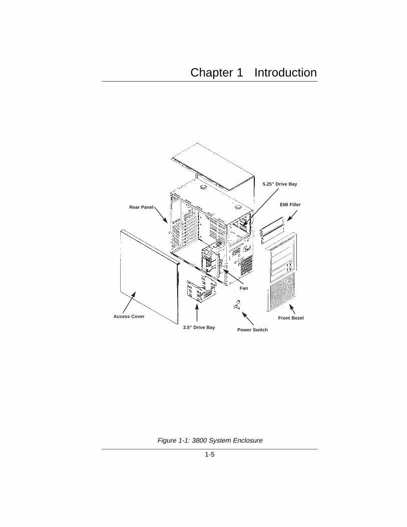
Figure 1-1: 3800 System Enclosure
Rear Panel
Access Cover
Power Switch3.5” Drive Bay
5.25” Drive Bay
Front Bezel
EMI Filler
Fan
Features
• PowerThe 3800 is equipped with a 200Wswitching 115/230VAC powersupply.
• CoolingFans in the chassis and power supply distribute cooling air through-out the enclosure.
• DrivesThe drive bay, with front panel acces, can accommodate up to threehalf-height (5⁄” or 3fi”) drives. An additional drive bay can holdthree half height 3fi” drives, one of which is externally available.
• Backplane/MotherboardThe 3800 is equipped with an ISA8-slot passive backplane, aPCI/ISAdual-bus passive backplane, or a motherboard. ThePCI/ISAbackplane contains four ISAslots, two PCI slots, oneshared ISAand PCI slot (only one of which can be used at a time),and one slot for the CPU board.
• Front Controls and IndicatorsThe reset switch, power switch, power on LED, and hard drive LEDare mounted on the front of the chassis.
Features
1-6

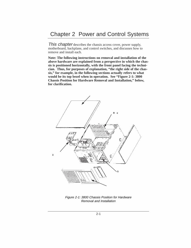
This chapter describes the chassis access cover, power supply,motherboard, backplane, and control switches, and discusses how toremove and install each.
Note: The following instructions on removal and installation of theabove hardware are explained from a perspective in which the chas-sis is positioned horizontally, with the front panel facing the techni-cian. Thus, for purposes of explanation, “the right side of the chas-sis,” for example, in the following sections actually refers to whatwould be its top bezel when in operation. See “Figure 2-1: 3800Chassis Position for Hardware Removal and Installation,” below,for clarification.
Chapter 2 Power and Control Systems
2-1
Figure 2-1: 3800 Chassis Position for Hardware Removal and Installation
5
3
R e
Power SupplyThe PS/2 style power supply measures 6.0"H x 3.4"Wx 5.5"D. Thepower supply constantly monitors the 115/230VAC input and asserts anactive power good signal.
• Changing the AC Input Selection SwitchThe input voltage may be set at 115VAC or 230VAC. To changethe input voltage:
• turn the system OFF,
• toggle the switch on the rear of the power supply to 115V or 230V and apply the corresponding voltage.
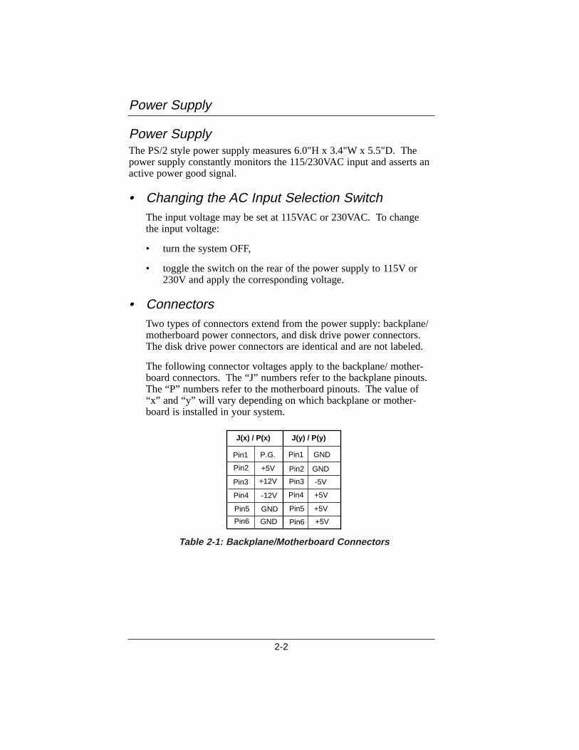
• ConnectorsTwo types of connectors extend from the power supply: backplane/motherboard power connectors, and disk drive power connectors.The disk drive power connectors are identical and are not labeled.
The following connector voltages apply to the backplane/ mother-board connectors. The “J” numbers refer to the backplane pinouts.The “P” numbers refer to the motherboard pinouts. The value of“x” and “y” will vary depending on which backplane or mother-board is installed in your system.
Power Supply
2-2
Pin2
Pin3
Pin4
Pin5
Pin6
P.G.
+5V
+12V
-12V
GND
GND
Pin2
Pin3
Pin4
Pin5
Pin6
GND
GND
-5V
+5V
+5V
+5V
Pin1Pin1
J(x) / P(x) J(y) / P(y)
Table 2-1: Backplane/Motherboard Connectors
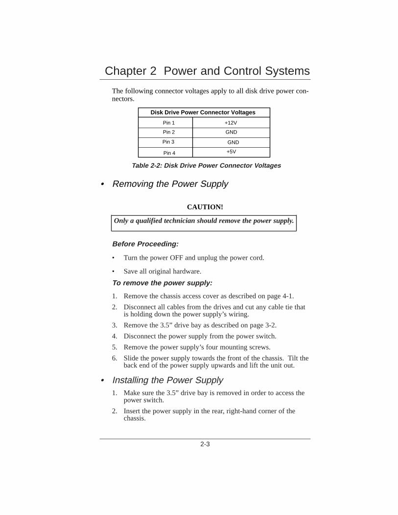
The following connector voltages apply to all disk drive power con-nectors.
• Removing the Power Supply
CAUTION!
Only a qualified technician should remove the power supply.
Before Proceeding:
• Turn the power OFF and unplug the power cord.
• Save all original hardware.
To remove the power supply:
1. Remove the chassis access cover as described on page 4-1.
2. Disconnect all cables from the drives and cut any cable tie thatis holding down the power supply’s wiring.
3. Remove the 3.5” drive bay as described on page 3-2.
4. Disconnect the power supply from the power switch.
5. Remove the power supply’s four mounting screws.
6. Slide the power supply towards the front of the chassis. Tilt theback end of the power supply upwards and lift the unit out.
• Installing the Power Supply1. Make sure the 3.5” drive bay is removed in order to access the
power switch.
2. Insert the power supply in the rear, right-hand corner of thechassis.
Chapter 2 Power and Control Systems
2-3
Disk Drive Power Connector Voltages
Pin 1
Pin 2
Pin 3
Pin 4
+12V
GND
GND
+5V
Table 2-2: Disk Drive Power Connector V oltages
3. Slide the back of the power supply under the tabs on the bottomof the chassis.
4. Slide the power supply toward the back of the chassis. Wheninserted properly, the power supply's INPUTconnector will beexposed through the rear chassis wall.
5. Attach the power switch to the wiring harness.
6. Insert the power supply’s four mounting screws.
• Removing the Backplane/Motherboard
CAUTION!
Only a qualified technician should remove the backplane ormotherboard.
CAUTION!
Components on the backplane and motherboard are sensitive todamage from Electrostatic Discharge (ESD). Handling of thisboard should ONLY be done by a properly trained technician inan approved ESD work area!
1. Remove the chassis access cover as described on page 4-1.
2. Disconnect any cables attached to the backplane/motherboard.
3. Remove the expansion cards from the backplane/motherboardas described on page 3-1.
4. Remove the backplane’s/motherboard’s mounting screws. Liftthe backplane/motherboard out of the chassis.
• Installing the Backplane/Motherboard1. Place the backplane/motherboard in the chassis, positioning it
so that its power connectors are on the side closest to the powersupply. Align the mounting holes on the backplane/mother-board with those on the chassis.
2. Insert the mounting screws and tighten them.
3. Reconnect the power connectors.
Installing the Power Supply
2-4
4. Install the expansion card(s) firmly into the backplane/mother-board as described on page 3-2.
5. Attach all cables and connectors to the expansion cards.
CAUTION!
Over-tightening the screws may damage the backplane or motherboard
SwitchesThe 3800 has one power switch and one reset switch, both located onthe front control panel in the center of the chassis.
• Removing the Power SwitchBefore proceeding:
• Turn the power OFF and unplug the power cord.
• Save all original hardware.To remove the power switch:
1. Remove the chassis access cover as explained on page 4-1.
2. Remove the 3.5” drive bay as explained on page 3-2.
3. Remove the power supply connectors from the power switch.
4. Remove the power switch’s mounting screw from the chassis.
5. Lift the power switch out of the chassis.
Chapter 2 Power and Control Systems
2-5
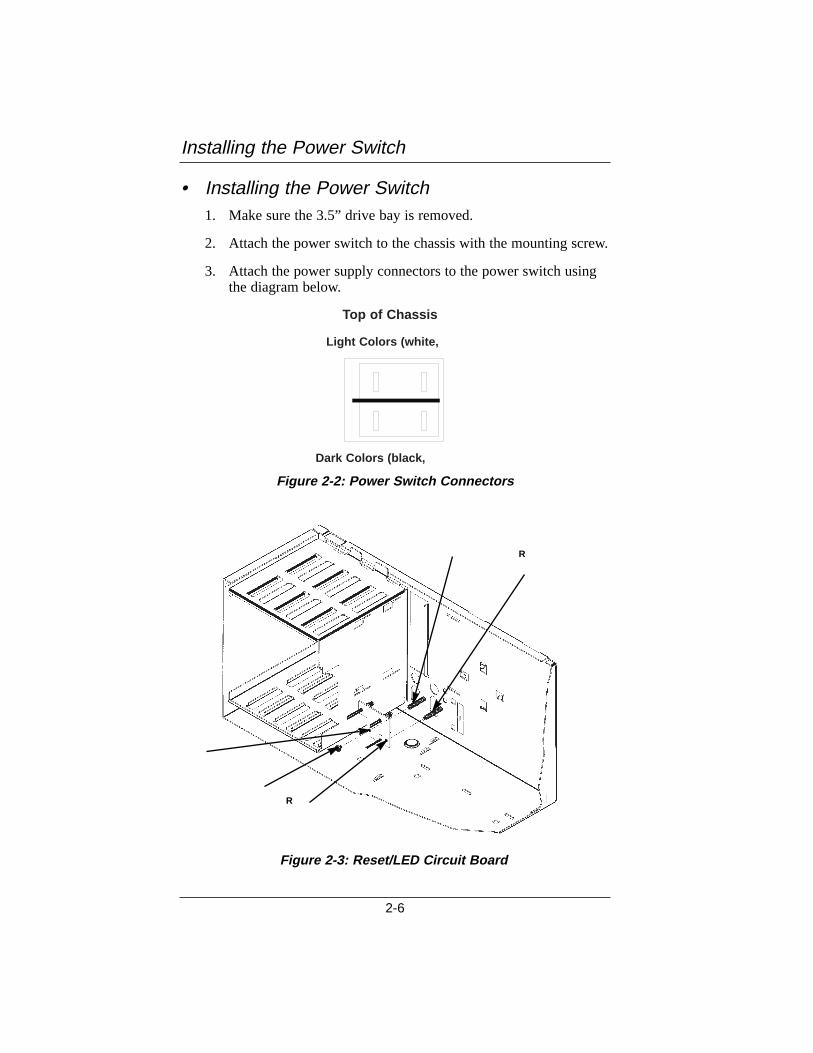
• Installing the Power Switch1. Make sure the 3.5” drive bay is removed.
2. Attach the power switch to the chassis with the mounting screw.
3. Attach the power supply connectors to the power switch using the diagram below.
Installing the Power Switch
2-6
Top of Chassis
Light Colors (white,
Dark Colors (black,
Figure 2-3: Reset/LED Circuit Board
Figure 2-2: Power Switch Connectors
R
R
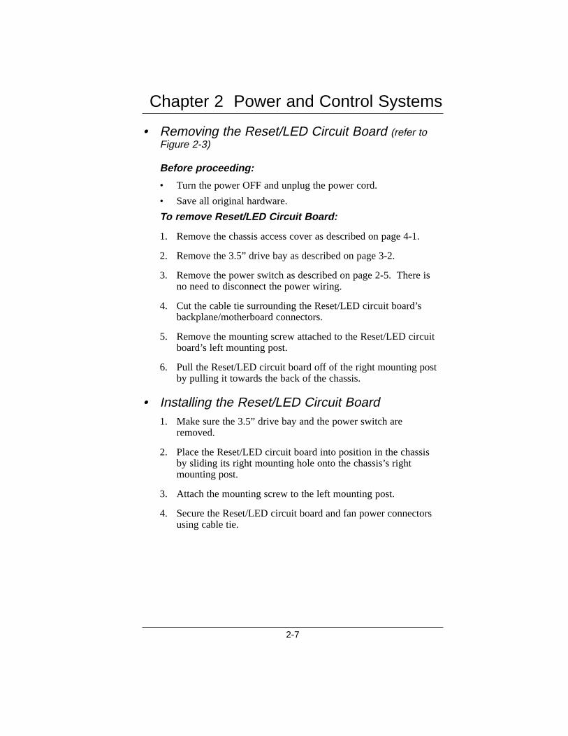
• Removing the Reset/LED Circuit Board (refer to Figure 2-3)
Before proceeding:
• Turn the power OFF and unplug the power cord.
• Save all original hardware.
To remove Reset/LED Circuit Board:
1. Remove the chassis access cover as described on page 4-1.
2. Remove the 3.5” drive bay as described on page 3-2.
3. Remove the power switch as described on page 2-5. There is no need to disconnect the power wiring.
4. Cut the cable tie surrounding the Reset/LED circuit board’s backplane/motherboard connectors.
5. Remove the mounting screw attached to the Reset/LED circuit board’s left mounting post.
6. Pull the Reset/LED circuit board off of the right mounting post by pulling it towards the back of the chassis.
• Installing the Reset/LED Circuit Board1. Make sure the 3.5” drive bay and the power switch are
removed.
2. Place the Reset/LED circuit board into position in the chassis by sliding its right mounting hole onto the chassis’s right mounting post.
3. Attach the mounting screw to the left mounting post.
4. Secure the Reset/LED circuit board and fan power connectors using cable tie.
Chapter 2 Power and Control Systems
2-7

This chapter describes the installation and removal of the expan-sion cards, drive bays, and drives in your 3800 system enclosure.
Note: The following instructions on removal and installation of theabove peripherals are explained from a perspective in which thechassis is positioned horizontally, with the front panel facing thetechnician. Thus, for purposes of explanation, “the right side of thechassis,” for example, in the following sections actually refers towhat would be its top bezel when in operation. See “Figure 2-1:3800 Chassis Position for Hardware Removal and Installation,” p. 2-1, for clarification.
CAUTION!
Electrostatic Discharge (ESD) may damage memory chips,programmed devices and other electrical components. ESDcan be prevented by wearing a wrist strap attached to aground post on a static mat.
• Removing an Expansion CardBefore Proceeding:
• Turn the power OFF and unplug the power cord.
• Save all original hardware.
To remove an expansion card
1. Remove the chassis access cover as described on page 4-1.
2. Disconnect any cables and connectors from the expansion card.
3. Take out the mounting screw.
4. Pull up on the expansion card and lift it out of the back-plane/motherboard.
Chapter 3 Peripheral Installation
3-1
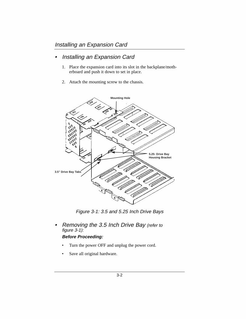
• Installing an Expansion Card
1. Place the expansion card into its slot in the backplane/moth-erboard and push it down to set in place.
2. Attach the mounting screw to the chassis.
• Removing the 3.5 Inch Drive Bay (refer to figure 3-1):
Before Proceeding:
• Turn the power OFF and unplug the power cord.
• Save all original hardware.
Installing an Expansion Card
3-2
Figure 3-1: 3.5 and 5.25 Inch Drive Bays
Mounting Hole
5.25: Drive BayHousing Bracket
3.5” Drive Bay T abs

To remove the 3.5 inch drive bay
1. Remove the chassis access cover as described on p. 4-1.
2. Disconnect all cables from all drives in the drive bay.
3. Remove the drive bay’s two mounting screws (one on the 5.25” drive bay, one on the mounting bracket).
4. Slide the drive bay toward the back of the chassis and lift it out.
• Installing the 3.5 Inch Drive Bay (refer to figure 3-1):
1. Slide the drive bay into place inside the chassis, making sure to fit its two tabs into place inside the slots on the housing bracket of the 5.25” drive bay.
2. Attach the two mounting screws.
• Removing the 3.5 Inch Floppy DriveBefore Proceeding:
1. Turn the power OFF and unplug the power cord.
2. Save all original hardware.
To remove the 3.5 inch floppy drive:
1. Remove the 3.5” drive bay as described on page 3-2.
2. Remove the four mounting screws attaching the floppy drive tothe drive bay.
3. Slide the floppy drive out of the drive bay.
• Installing the 3.5 Inch Floppy Drive1. Slide the floppy drive into the front of the drive bay.
2. Mount the floppy drive so that it is flush with the front bezel. Some adjustment may be required depending on the particular floppy drive used.
3. Attach the floppy drive’s four mounting screws to the drive bay.
Chapter 3 Peripheral Installation
3-3
• Removing the Hard Drive1. Remove the 3.5” drive bay as described on page 3-2.
2. Remove the four mounting screws attaching the hard drive to the drive bay.
3. Slide the hard drive out of the drive bay.
• Installing the Hard Drive1. Slide the hard drive into the drive bay.
2. Attach the hard drive’s four mounting screws.
Removing the Hard Drive
3-4
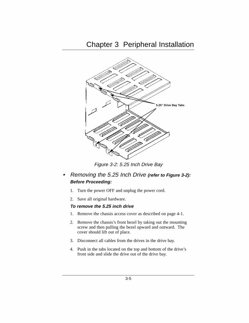
• Removing the 5.25 Inch Drive (refer to Figure 3-2):Before Proceeding:
1. Turn the power OFF and unplug the power cord.
2. Save all original hardware.
To remove the 5.25 inch drive
1. Remove the chassis access cover as described on page 4-1.
2. Remove the chassis’s front bezel by taking out the mounting screw and then pulling the bezel upward and outward. The cover should lift out of place.
3. Disconnect all cables from the drives in the drive bay.
4. Push in the tabs located on the top and bottom of the drive’s front side and slide the drive out of the drive bay.
Chapter 3 Peripheral Installation
3-5
5.25” Drive Bay T abs
Figure 3-2: 5.25 Inch Drive Bay
• Installing the 5.25 Inch Drive (refer to Figure 3-2):
1. Mount the drive slides on the drive. The “B” slide goes on the top of the drive and the “A” slide goes on the bottom. The let-ter should be right-side-up when read while facing the drive from its front.
2. Slide the drive into the bay as far as it will go. When it is impeded by the tabs located on the top and bottom of the drive’s front side, press down on the tabs and slide the drive further into the bay.
3. Verify that the drive is locked into place.
Installing the 5.25 Inch Drive
3-6
This chapter discusses the removal and installation of the chassisaccess cover, fan, and fan bracket.
Note: The following instructions on removal and installation of theabove hardware are explained from a perspective in which the chas-sis is positioned horizontally, with the front panel facing the techni-cian. Thus, for purposes of explanation, “the right side of the chas-sis,” for example, in the following sections actually refers to whatwould be its top bezel when in operation. See “Figure 2-1: 3800Chassis Position for Hardware Removal and Installation,” p. 2-1,for clarification.
• Removing the Chassis Access CoverBefore Proceeding:
• Turn the power OFF and unplug the power cord.
• Save all original hardware.
To remove the chassis access cover:
1. Remove the chassis access cover’s two mounting screws.
2. Slide the cover toward the rear of the chassis approximately oneinch and lift the cover up.
• Replacing the Chassis Access Cover1. Position the access cover on the chassis and slide it into place.
2. Attach the two mounting screws.
FanThe fan provides forced air to cool the expansion cards.
Chapter 4 Hardware
4-1
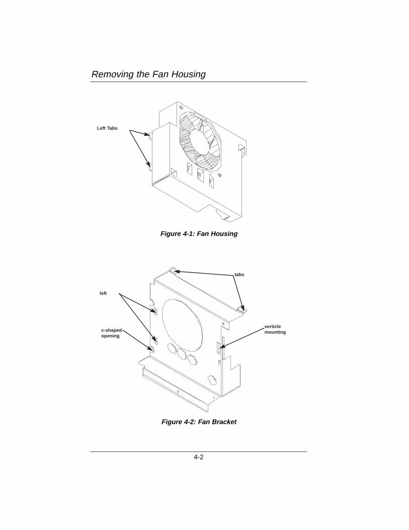
Removing the Fan Housing
4-2
Figure 4-1: Fan Housing
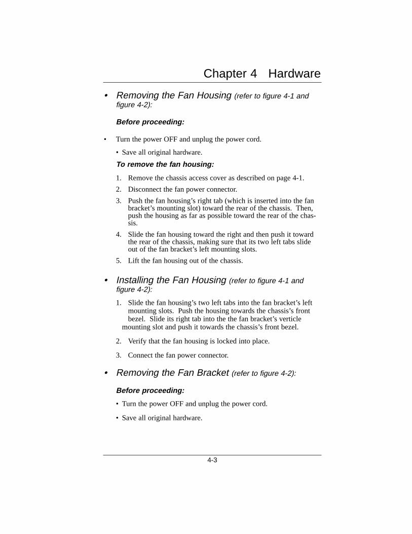
Figure 4-2: Fan Bracket
Left Tabs
left
verticlemountingc-shaped
opening
tabs
• Removing the Fan Housing (refer to figure 4-1 and figure 4-2):
Before proceeding:
• Turn the power OFF and unplug the power cord.
• Save all original hardware.
To remove the fan housing:
1. Remove the chassis access cover as described on page 4-1.
2. Disconnect the fan power connector.
3. Push the fan housing’s right tab (which is inserted into the fanbracket’s mounting slot) toward the rear of the chassis. Then,push the housing as far as possible toward the rear of the chas-sis.
4. Slide the fan housing toward the right and then push it towardthe rear of the chassis, making sure that its two left tabs slideout of the fan bracket’s left mounting slots.
5. Lift the fan housing out of the chassis.
• Installing the Fan Housing (refer to figure 4-1 and figure 4-2):
1. Slide the fan housing’s two left tabs into the fan bracket’s left mounting slots. Push the housing towards the chassis’s front bezel. Slide its right tab into the the fan bracket’s verticle
mounting slot and push it towards the chassis’s front bezel.
2. Verify that the fan housing is locked into place.
3. Connect the fan power connector.
• Removing the Fan Bracket (refer to figure 4-2):
Before proceeding:
• Turn the power OFF and unplug the power cord.
• Save all original hardware.
Chapter 4 Hardware
4-3
To remove the fan bracket:
1. Remove the fan housing as described on p. 4-3.
2. Remove the fan bracket’s mounting screw.
3. Tilt the top of the fan bracket toward the back of the chassis and unhook its tabs from the slots in the bottom of the chassis.
4. Lift the fan bracket out of the chassis.
• Installing the Fan Bracket (refer to figure 4-2):
1. Tilt the top of the fan bracket toward the rear of the chassis. Slide the fan bracket’s tabs into the slots in the bottom of the chassis.
2. Route the speaker cables through the fan bracket’s bottom left c-shaped opening.
2. Attach the fan bracket’s mounting screw.
• Removing the Speaker
Before proceeding:
• Turn the power OFF and unplug the power cord.
• Save all original hardware.
To remove the speaker
1. Remove the chassis access cover as described on p. 4-1.
2. Remove the fan housing and the fan bracket as described on p. 4-3.
3. Disconnect the speaker connector from the backplane/moth-erboard.
4. Pull the speaker toward the rear of the chassis and out from under its mounting tabs. Some force may be necessary.
4-4
Removing the Speaker
• Installing the Speaker1. Make sure the fan and the fan bracket are removed.
2. Place the speaker over the straight mounting tab.
2. Slide the speaker under the three remaining (i.e.,bent) mountingtabs.
3. Attach the speaker connector to the backplane/motherboard.
4-5
Chapter 4 Hardware

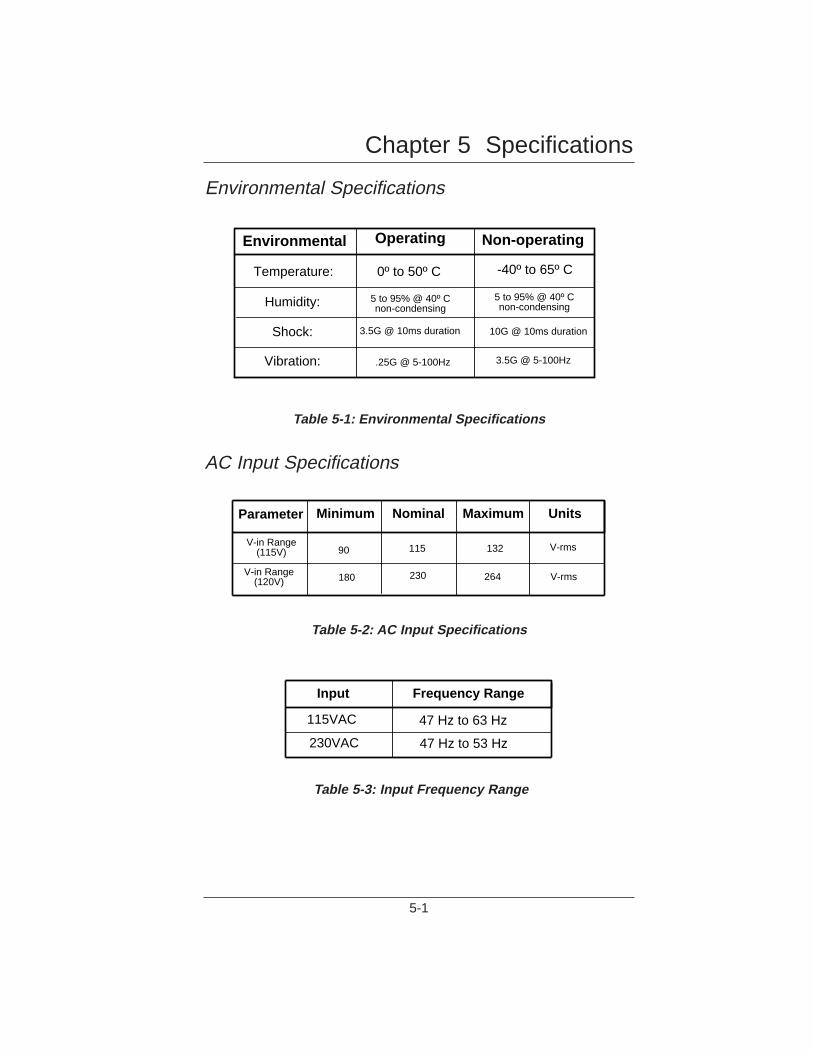
Environmental Specifications
Table 5-1: Environmental Specifications
AC Input Specifications
Table 5-2: AC Input Specifications
Table 5-3: Input Frequency Range
Chapter 5 Specifications
5-1
Environmental Operating Non-operating
Temperature:
Humidity:
Shock:
Vibration:
0º to 50º C -40º to 65º C
5 to 95% @ 40º Cnon-condensing
5 to 95% @ 40º Cnon-condensing
3.5G @ 10ms duration 10G @ 10ms duration
.25G @ 5-100Hz 3.5G @ 5-100Hz
Parameter Minimum Nominal Maximum Units
V-in Range(115V) 90 115 132 V-rms
V-in Range(120V) 180 230 264 V-rms
Input Frequency Range
115VAC
230VAC
47 Hz to 63 Hz
47 Hz to 53 Hz
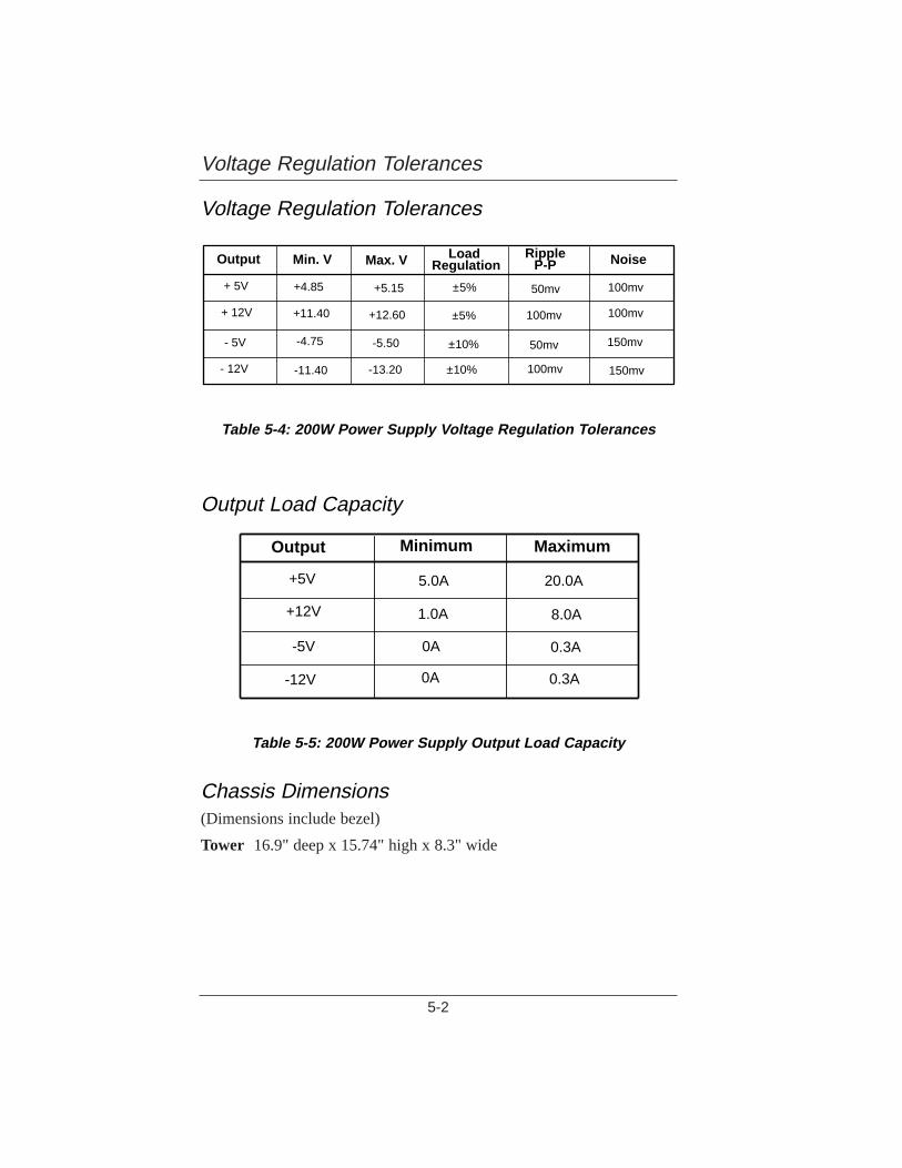
Voltage Regulation Tolerances
Table 5-4: 200W Power Supply V oltage Regulation T olerances
Output Load Capacity
Table 5-5: 200W Power Supply Output Load Capacity
Chassis Dimensions(Dimensions include bezel)
Tower 16.9" deep x 15.74" high x 8.3" wide
Voltage Regulation Tolerances
5-2
Output Min. V Max. V Load Regulation
RippleP-P Noise
+ 5V
+ 12V
- 5V
- 12V
+4.85
+11.40
-4.75
-11.40
+5.15
+12.60
-5.50
-13.20
±5%
±5%
±10%
±10%
50mv
100mv
50mv
100mv
100mv
100mv
150mv
150mv
Output Minimum Maximum
+5V
+12V
-5V
-12V
5.0A
1.0A
0A
0A
20.0A
8.0A
0.3A
0.3A

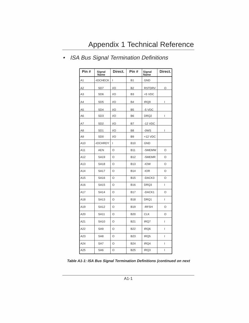
• ISA Bus Signal Termination Definitions
Table A1-1: ISA Bus Signal Termination Definitions (continued on next
Pin # Signal Direct. Pin # Signal Direct.Name Name
A1 -IOCHECK I B1 GND
A2 SD7 I/O B2 RSTDRV O
A3 SD6 I/O B3 +5 VDC
A4 SD5 I/O B4 IRQ9 I
A5 SD4 I/O B5 -5 VDC
A6 SD3 I/O B6 DRQ2 I
A7 SD2 I/O B7 -12 VDC
A8 SD1 I/O B8 -0WS I
A9 SD0 I/O B9 +12 VDC
A10 -IOCHRDY I B10 GND
A11 AEN O B11 -SMEMW O
A12 SA19 O B12 -SMEMR O
A13 SA18 O B13 -IOW O
A14 SA17 O B14 -IOR O
A15 SA16 O B15 -DACK3 O
A16 SA15 O B16 DRQ3 I
A17 SA14 O B17 -DACK1 O
A18 SA13 O B18 DRQ1 I
A19 SA12 O B19 -RFSH O
A20 SA11 O B20 CLK O
A21 SA10 O B21 IRQ7 I
A22 SA9 O B22 IRQ6 I
A23 SA8 O B23 IRQ5 I
A24 SA7 O B24 IRQ4 I
A25 SA6 O B25 IRQ3 I
Appendix 1 Technical Reference
A1-1
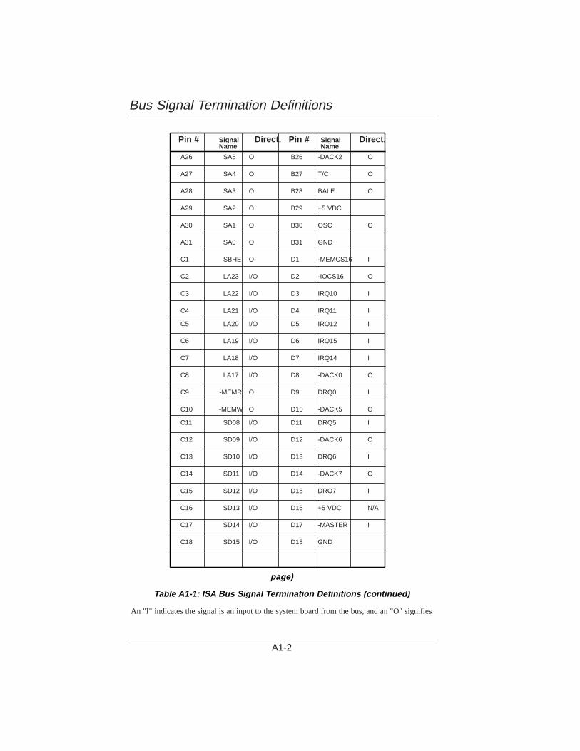
page)
Table A1-1: ISA Bus Signal T ermination Definitions (continued)
An "I" indicates the signal is an input to the system board from the bus, and an "O" signifies
Bus Signal Termination Definitions
A1-2
Pin # Signal Direct. Pin # Signal Direct.Name Name
A26 SA5 O B26 -DACK2 O
A27 SA4 O B27 T/C O
A28 SA3 O B28 BALE O
A29 SA2 O B29 +5 VDC
A30 SA1 O B30 OSC O
A31 SA0 O B31 GND
C1 SBHE O D1 -MEMCS16 I
C2 LA23 I/O D2 -IOCS16 O
C3 LA22 I/O D3 IRQ10 I
C4 LA21 I/O D4 IRQ11 I
C5 LA20 I/O D5 IRQ12 I
C6 LA19 I/O D6 IRQ15 I
C7 LA18 I/O D7 IRQ14 I
C8 LA17 I/O D8 -DACK0 O
C9 -MEMR O D9 DRQ0 I
C10 -MEMW O D10 -DACK5 O
C11 SD08 I/O D11 DRQ5 I
C12 SD09 I/O D12 -DACK6 O
C13 SD10 I/O D13 DRQ6 I
C14 SD11 I/O D14 -DACK7 O
C15 SD12 I/O D15 DRQ7 I
C16 SD13 I/O D16 +5 VDC N/A
C17 SD14 I/O D17 -MASTER I
C18 SD15 I/O D18 GND
an output from the system board to the bus.
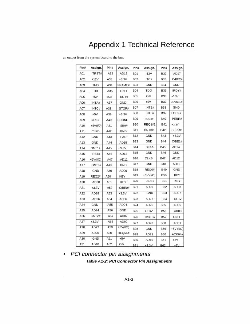
• PCI connector pin assignmentsTable A1-2: PCI Connector Pin Assignments
Appendix 1 Technical Reference
A1-3
Pin# Assign. Pin# Assign.
A01 TRST# A32 AD16
A02 +12V A33 +3.3V
A03 TMS A34 FRAME#
A04 TDI A35 GND
A05 +5V A36 TRDY#
A06 INTA# A37 GND
A07 INTC# A38 STOP#
A08 +5V A39 +3.3V
A09 CLKC A40 SDONE
A10 +5V(I/0) A41 SB0#
A11 CLKD A42 GND
A12 GND A43 PAR
A13 GND A44 AD15
A14 GNT1# A45 +3.3V
A15 RST# A46 AD13
A16 +5V(I/O) A47 AD11
A17 GNT0# A48 GND
A18 GND A49 AD09
A19 REQ2# A50 KEY
A20 AD30 A51 KEY
A21 +3.3V A52 C/BE0#
A22 AD28 A53 +3.3V
A23 AD26 A54 AD06
A24 GND A55 AD04
A25 AD24 A56 GND
A26 GNT2# A57 AD02
A27 +3.3V A58 AD00
A28 AD22 A59 +5V(I/O)
A29 AD20 A60 REQ64#
A30 GND A61 +5V
A31 AD18 A62 +5V
Pin# Assign. Pin# Assign.
B01 -12V B32 AD17
B02 TCK B33 C/BE2#
B03 GND B34 GND
B04 TDO B35 IRDY#
B05 +5V B36 +3.3V
B06 +5V B37 DEVSEL#
B07 INTB# B38 GND
B08 INTD# B39 LOCK#
B09 REQ3# B40 PERR#
B10 REQ1#1 B41 +3.3V
B11 GNT3# B42 SERR#
B12 GND B43 +3.3V
B13 GND B44 C/BE1#
B14 CLKA B45 AD14
B15 GND B46 GND
B16 CLKB B47 AD12
B17 GND B48 AD10
B18 REQ0# B49 GND
B19 +5V (I/O) B50 KEY
B20 AD31 B51 KEY
B21 AD29 B52 AD08
B22 GND B53 AD07
B23 AD27 B54 +3.3V
B24 AD25 B55 AD05
B25 +3.3V B56 AD03
B26 C/BE3# B57 GND
B27 AD23 B58 AD01
B28 GND B59 +5V (I/O)
B29 AD21 B60 ACK64#
B30 AD19 B61 +5V
B31 +3.3V B62 +5V

Bbackplane: A device containing slots, or sockets, for plugging in
boards or cables.
bidirectional parallel port: An eight-bit port that can be used for aninput as well as an output device.
bus: One or more electrical conductors that transmit power or binarydata to the various sections of a computer or any common pathwaybetween hardware devices. A computer bus connects the CPU to itsmain memory and the memory banks that reside on the control unitsof the peripheral devices. It is made up of two parts. Addresses aresent over the address bus to signal a memory location, and the datais transferred over the data bus to that location.
Ccard cage: A cabinet or metal frame that holds printed circuit cards.
CMOS (Complementary Metal Oxide Semiconductor):A techniqueof arranging transistors which uses very low power.
Ddisk access LED: The LED located on the front control panel that indi-
cates when the hard disk drive is active.
EElectrostatic Discharge (ESD): Stationary electrical charges in which
no current flows. Many components on your SBC and in the enclo-sure are sensitive to damage caused by ESD. ESD can be preventedby wearing a wrist strap attached to a ground post on a static mat.
EMI (ElectroMagnetic Interference): Noise generated by the switch-ing action of the power supply and other system components.Conducted EMI is radiation reflected back into the power line,
Appendix 2 Glossary of Terms
A2-1
which is normally controlled with a line filter. Radiated EMI is thatportion that would radiate into free space, but is suppressed byenclosing a power supply's circuitry in a metal case. The FCC gov-erns conducted and radiated emission levels in the U.S.
expansion card: A printed circuit board that plugs into an expansionslot.
Ffr ont control panel: The small panel on the front of the computer that
contains the power switch, reset switch, Power ON LED, the diskaccess LED, and the keyboard connector.
Hhold-down bar: Located directly beneath the top cover, the hold-down
bar is mounted over the expansion slots on the backplane. Its pur-pose is to hold the expansion cards securely in their slots.
IIDE (Integrated Drive Electronics): A standard of signalling and
communicating with a device.
Kkeyboard connector: The five-pin connector located on the front con-
trol panel.
Kilobyte (KB): 1,024 bytes.
Pparallel port: I/O connector used to hook up a printer or other parallel
interface device. The parallel port is usually a 25-pin female DB25connector.
Appendix 2 Glossary of Terms
A2-2
port: Ports are used to connect peripheral devices such as external dri-ves and printers to your computer.
power good: Signal used to prevent the computer from starting untilthe power has stabilized. The power good line switches from 0 to+5 volts within one tenth to one half second after the power supplyreaches normal voltage levels. Whenever low input voltage causesthe output voltage to fall below operating levels, the power goodsignal goes back to zero.
Power ON LED: The LED located on the front control panel that indi-cates that power is present in the computer.
power switch: Located on the front control panel, the power switchturns power ON to the computer.
power supply: Electrical system that converts AC current from thewall outlet into the DC currents required by the computer circuitry.In a personal computer, +5, -5, +12 and -12 voltages are generated.The 5 volts are used for the electronic circuitry, and the 12 volts arerequired for the drives.
RReal-time clock (RTC): A periodic interrupt used to derive local time.
reset switch: Computer button or key that reboots the computer. Allcurrent activities are stopped cold and any data in memory is lost.
retaining bracket: The bracket on the back of the chassis that holdsconnectors from the board, usually a DB9 for serial port, a DB25for parallel port, and mini-DIN connectors for keyboard and mouse.
Sserial port: A two-channel port, one channel used for "In" transmis-
sions and one for "Out" transmissions.
Appendix 2 Glossary of Terms
A2-3

SCSI (Small ComputerSystem Interface): A high speed, general pur-pose interface to storage devices.
Appendix 2 Glossary of Terms
A2-4
This appendix provides illustrations of the 3800 system enclosureconfiguratios, the 8-slot ISA backplane, the 8-slot PCI/ISAbackplane,and the system interconnect diagram.
ConfigurationsThe 3800 system enclosure is available in a tower configuration.
8-Slot ISA Passive BackplaneA fold-out illustration of the 8-slot backplane shows all the connectors.J1 through J8 are the expansion card slots. J11 through J14 are thebackplane power connectors.
8-slot PCI/ISA Dual-Bus Passive BackplaneA fold-out illustration of the 8-slot dual-bus passive backplane shows allthe connectors. J1, J2, J3, and J5 are ISA connectors. J4/J10 is for theCPU board. J8 and J9 are PCI expansion slots. And J6/J7 is a sharedISA and PCI slot, only one of which can be used at a time.
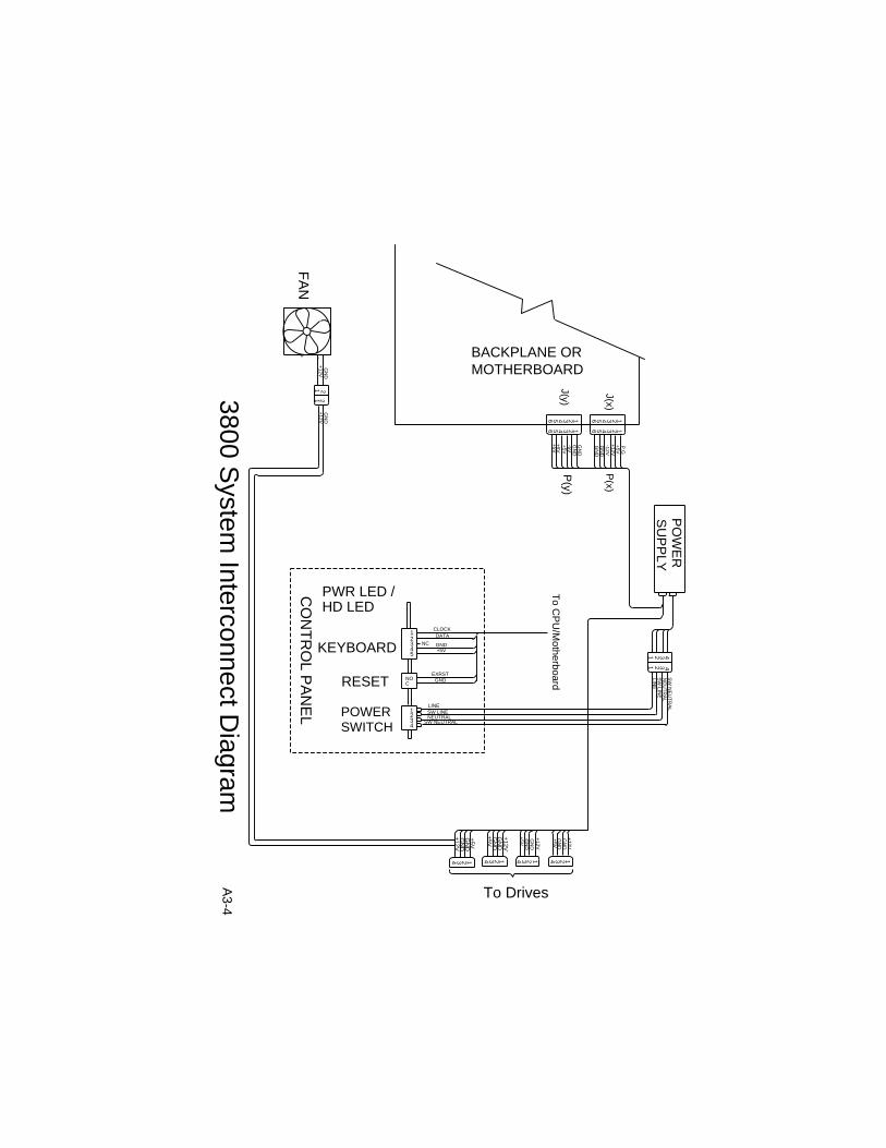
3800 System Enclosure Interconnect DiagramA fold-out illustration shows the interconnection of the components ofthe 3800 system enclosure, including pin-out descriptions of the connec-tors.
Appendix 3 Illustrations
A3-1
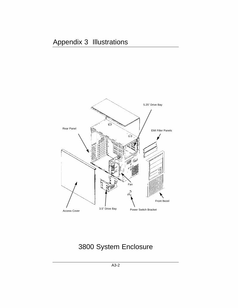
3800 System Enclosure
Appendix 3 Illustrations
A3-2
Access Cover3.5” Drive Bay Power Switch Bracket
Rear PanelEMI Filler Panels
5.25” Drive Bay
Fan
Front Bezel
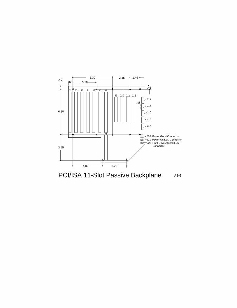
.65.40
.45
3.10
5.30
6.10
3.45
4.00 3.20
2.35 1.45
J1 J2 J3 J4 J5 J7
J9 J10 J11 J12
J6
J8
J13
J14
J15
J16
J17
J22 Hard Drive Access LED Connector
J21 Power On LED ConnectorJ20 Power Good Connector
J18
PCI/ISA 11-Slot Passive Backplane A3-6
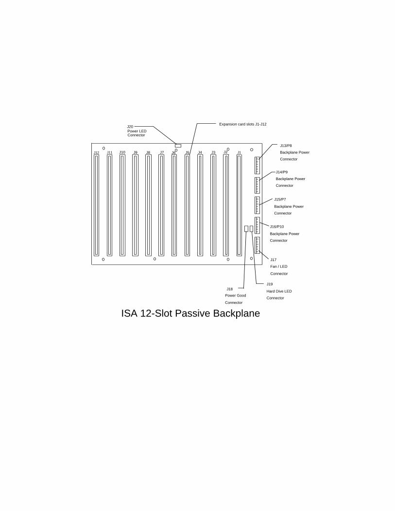
J13/P8
Backplane Power
Connector
J14/P9
Backplane Power
Connector
J15/P7
Backplane Power
Connector
J16/P10
Backplane Power
Connector
J17
Fan / LED
Connector
J19
Hard Dive LED
Connector
J18
Power Good
Connector
J20Power LEDConnector
J1J12
Expansion card slots J1-J12
ISA 12-Slot Passive Backplane
J11 J10 J9 J8 J7 J6 J5 J4 J3 J2
443
32
21
1
SW
NE
UT
RA
L
LINE
SW
LINE
NE
UT
RA
L
BACKPLANE ORMOTHERBOARD
11
22
334
4
66
55
P(y)
+5V
+5V
+5V
GN
DG
ND
-5VJ(y)
GN
DG
ND
-12V
P.G
+5V
+12V
J(x)
PO
WE
R
SU
PP
LY
+12V
GN
D
+5V
GN
D
4 3 2 1 1234
GN
D+
12V
GN
D+
5V
+5VG
ND
+12V
GN
D
4 3 2 1
+5V
GN
D
+12V
GN
D
4 3 2 1
To Drives
56 4 3 2 1
A3-4
12346 5
P(x)
GNDEXRST
CLOCK
NC
RESET
KEYBOARD
CNO
12345
CO
NT
RO
L PA
NE
L
DATA
GND+5V
4321POWER
SWITCH
PWR LED /HD LED
LINESW LINENEUTRAL
SW NEUTRAL
FA
N
-+
GN
D+
12V1
12
2+
12VG
ND
To C
PU
/Motherboard
3800 System
Interconnect Diagram
This chassis has been tested and iscompliant with Low VoltageDirective 73123/EEC. If equipmentother than I-Bus manufacture isinstalled in the chassis, retestingmay be required to assure compli-ance.
060-41003-00 Rev A.
This device complies with Part 15 of the FCC Rules. Operationis subject to the following two conditions: (1) this device maynot cause harmful interference, and (2) this device must acceptany interference received including interference that may causeundesired operation.*
WARNING: This equipment has been tested and found to com-ply with the limits for a Class “A” digital device, pursuant to part15 of the FCC Rules. These limits are designed to provide rea-sonable protection against harmful interference when the equip-ment is operated in a commercial environment. This equipmentgenerates, uses and can radiate radio frequency energy and, if notinstalled and used in accordance with the instruction manual,may cause interference to radio communications. Operation ofthis equipment in a residential area is likely to cause harmfulinterference in which case uses will be required to correct theinterference at their own expense.
Changes or modifications not expressly approved by the partyresponsible for compliance could void the user’s authority tooperate the equipment.
NOTE: This product was FCC verified under test conditionsthat included the use of shielded I/O cables and connectorsbetween system components. To be in compliance with FCCregulations, the user must use shielded cables and connectorsand install them properly.
*FCC compliance applies only if the following conditions aremet: (1) the CPU board enclosed in this package or accompany-ing this manual is installed in an I-Bus chassis, or (2) the chassisenclosed in this package or accompanying this manual containsan I-Bus enclosure.