manipulation of objects with tethers and millirobots
TRANSCRIPT

Manipulation of Objects with Tethers and Millirobots
Tiffany Cappellari
Electrical Engineering and Computer SciencesUniversity of California, Berkeley
Technical Report No. UCB/EECS-2021-53
http://www2.eecs.berkeley.edu/Pubs/TechRpts/2021/EECS-2021-53.html
May 12, 2021

Copyright © 2021, by the author(s).All rights reserved.
Permission to make digital or hard copies of all or part of this work forpersonal or classroom use is granted without fee provided that copies arenot made or distributed for profit or commercial advantage and that copiesbear this notice and the full citation on the first page. To copy otherwise, torepublish, to post on servers or to redistribute to lists, requires prior specificpermission.
Acknowledgement
I would like to thank Professor Ronald Fearing for all his guidance andsupport in my research for the last few years as well as the members of theBiomimetic Millisystems Lab and Jay Monga for his assistance in runningexperiments and with control related issues. I would also like to thankProfessor Hannah Stuart for agreeing to be the second reader for thisthesis and for her input in the editing process. I am also incredibly grateful to my parents for their unconditional supportthroughout the entirety of my undergraduate and graduate career thus farand would like to thank them for all the sacrifices they have made so that Icould pursue my passions.
Manipulation of Objects with Tethers and Millirobots
by Tiffany Cappellari
Research Project
Submitted to the Department of Electrical Engineering and Computer Sciences, University of California at Berkeley, in partial satisfaction of the requirements for the degree of Master of Science, Plan II. Approval for the Report and Comprehensive Examination:
Committee:
Professor Ronald S. Fearing Research Advisor
(Date)
* * * * * * *
Professor Hannah Stuart Second Reader
(Date)
May 12, 2021

1
Abstract
Manipulation of an Object with Tethers and Millirobots
by
Tiffany Cappellari
Master of Science in Electrical Engineering and Computer Science
University of California, Berkeley
Professor Ronald Fearing, Chair
Robots possess great potential to help people within their homes with a variety of householdchores such as organization and picking things up; however, tasks such as these require a highlevel of dexterity usually found in large, expensive armed robots that would be inconvenient,unaffordable, and intrusive in a typical home. Millirobots, on the other hand, could be a muchmore viable option as they are more cost effective for the average person and would be smaller,safer, and less obtrusive in the home. Millirobots with the capability to manipulate objectscan be used in a number of ways; for example, in the home of a disabled and/or elderly personliving alone, these robots can help with everyday tasks that may be difficult for this person toaccomplish on their own such as removing tripping hazards, up righting fallen furniture, andfetching hard-to-reach objects. This project explores millirobots’ ability to perform graspingand manipulation tasks on larger objects comparable to typical armed robots through the useof tethers and winches. The code can be found at https://github.com/tiffanyec/tether botsand videos of the experiments can be found at https://youtu.be/8aOS7uYwEYE.

i
Dedicated to the memories of my uncle, who always encouraged me to pursue my passions.

ii
Contents
Contents ii
List of Figures iii
List of Tables v
1 Introduction 1
2 Related Work 32.1 Tendon-Driven Hands . . . . . . . . . . . . . . . . . . . . . . . . . . . . . . . 32.2 Grasping . . . . . . . . . . . . . . . . . . . . . . . . . . . . . . . . . . . . . . 42.3 Robot Cooperation . . . . . . . . . . . . . . . . . . . . . . . . . . . . . . . . 4
3 Problem Formulation 63.1 Geometric Model . . . . . . . . . . . . . . . . . . . . . . . . . . . . . . . . . 63.2 Control Model . . . . . . . . . . . . . . . . . . . . . . . . . . . . . . . . . . . 12
4 Experiments and Setup 154.1 Simulation . . . . . . . . . . . . . . . . . . . . . . . . . . . . . . . . . . . . . 154.2 Experiments . . . . . . . . . . . . . . . . . . . . . . . . . . . . . . . . . . . . 18
5 Results 205.1 Velocity vs Torque Controller Comparison . . . . . . . . . . . . . . . . . . . 20
6 Discussion and Conclusion 30
Bibliography 32

iii
List of Figures
1.1 A set of millirobots helping a person around their home by removing potentialtripping hazards and using tethers to upright a fallen chair. These robots havemulti-surface capabilities and can rapidly get out of the person’s way. Credit:Hannah Stuart . . . . . . . . . . . . . . . . . . . . . . . . . . . . . . . . . . . . 2
2.1 Examples of tendon driven mechanisms: (a) and (c) are tendon-driven mecha-nisms, but (b) is not [12]. . . . . . . . . . . . . . . . . . . . . . . . . . . . . . . 3
2.2 Quadroters using tethers to lift objects. Left: [13]; Right: CALM [16]. . . . . . . 52.3 Two robots reorienting a couch [15]. . . . . . . . . . . . . . . . . . . . . . . . . 5
3.1 A 2D rectangular object of mass M and length 2r suspended in the air by twotethers with tensions t1 and t2. . . . . . . . . . . . . . . . . . . . . . . . . . . . 7
3.2 A 2D rectangular object of mass M and length 2r being pulled on the ground bya tether with tension t1. . . . . . . . . . . . . . . . . . . . . . . . . . . . . . . . 8
3.3 A 2D rectangular object of mass M , length 2r, and height 2d being rotated bytwo tethers with tensions t1 and t2. . . . . . . . . . . . . . . . . . . . . . . . . 9
3.4 Our simulated robots attached a block object through tether. More detailedfigures can be found below at Figure 4.1 and 4.2. . . . . . . . . . . . . . . . . . 12
3.5 An illustration of the trajectory used to calculate the necessary linear acceleration.A similar method is used to find the angular acceleration. . . . . . . . . . . . . . 13
3.6 The overall control block diagram where the input to the system is the desiredposition and orientation of the block. Only the x position of the block is specifiedas the goal is to drag it across the ground with the attached tethers acting as thefingers of the grasp and will not lift it, thereby not changing its y-axis position. 14
4.1 A screenshot of the first simulation environment set up. A series of spherical jointsand shapes are chained together to create simulated tethers that are attached toa rectangular block object and two wheeled robots. Force sensors measure thetensions of the two tethers. . . . . . . . . . . . . . . . . . . . . . . . . . . . . . . 16
4.2 A screenshot of the second simulation environment set up. The tethers made ofspherical joints are now also attached to stiff springs. . . . . . . . . . . . . . . . 16
4.3 Plots comparing the performance of Bullet 2.83 and ODE. . . . . . . . . . . . . 17

iv
5.1 Images of the V-REP simulation before, during, and after rotating the object by-0.5 radians and translating it by 0.3 meters using the velocity controller. . . . . 21
5.2 Plots of the results of telling the system to rotate the object by -0.5 radians usingthe velocity controller. The first two plots show the calculated desired tensionsfor the two tether t1 and t2 needed to generate the necessary forces required tomove the block from its current position and orientation to its desired one as wellas the system’s actual measured tensions at each time step. The bottom two plotsshow the block’s change in position and orientation over time as it converges toapproximately the desired values. . . . . . . . . . . . . . . . . . . . . . . . . . . 22
5.3 Plots of the results of telling the system to move the block object to position0.2 along the x-axis using the velocity controller. Simply pure translation is notpossible with this simulation as the force of friction between the ground and theentire base of the block is too high for the robots to overcome so a small rotationof -0.08 rad is also applied to the object. This very small rotation results inoscillatory behavior once reaching the desired position. . . . . . . . . . . . . . . 23
5.4 Plots of the results of telling the system to move the block object to position 0.3along the x-axis and rotate it by -0.5 radians using the velocity controller. . . . 24
5.5 Plots of the results of telling the system to move the block object to position 0.3along the x-axis and rotate it by -0.6 radians using the velocity controller. . . . 25
5.6 Plots of the results of telling the system to move the block object to position 0.3along the x-axis and rotate it by -0.4 radians using the velocity controller. . . . 26
5.7 Plots of the results of pure translation of the object by 0.4 m using the torquecontroller. We can observe that the torque controller exhibits far more oscillatorybehavior than the velocity controller. This is most likely due to a combination ofa stick-slip friction phenomena, causing the robots to repeatedly need to overcomethe force of friction between the block and the ground, as well as the torque con-troller over-correcting each time it misses its goal. The controller over-correctingcould most likely be remedied with further tuning. . . . . . . . . . . . . . . . . 27
5.8 A plot of the velocity of the robots and block while translating the block 0.4 musing the torque controller. . . . . . . . . . . . . . . . . . . . . . . . . . . . . . 28
5.9 Close up snippets of the block angle, the block and robots’ positions, and theirvelocities as the torque controller translates the block 0.4 m. Although onlytranslation is requested, the angle of the block oscillates heavily as the blockcontinuously tips back and forth due to the robots over-correcting in each direction. 29

v
List of Tables
4.1 Conditions and wrenches needed in order to transform the object by a pure trans-lation, a pure rotation, and by both a rotation and a translation in the set-updepicted in Figure 4.1. . . . . . . . . . . . . . . . . . . . . . . . . . . . . . . . . 19

vi
Acknowledgments
I would like to thank Professor Ronald Fearing for all his guidance and support in myresearch for the last few years as well as the members of the Biomimetic Millisystems Laband Jay Monga for his assistance in running experiments and with control related issues. Iwould also like to thank Professor Hannah Stuart for agreeing to be the second reader forthis thesis and for her input in the editing process.
I am also incredibly grateful to my parents for their unconditional support throughoutthe entirety of my undergraduate and graduate career thus far and would like to thank themfor all the sacrifices they have made so that I could pursue my passions.
1
Chapter 1
Introduction
Robots have a large amount of potential to help people within their homes with a varietyof tasks such as household chores, medical assistance, and education [8], [14]. For example,there are many organization tasks within a home that are high on many people’s priority listssuch as clearing items around the house as well as picking things up and putting them away[1]. Tasks such as these require a high degree of dexterity that can be easily accomplishedwith large, industrial robots such as Baxter and Sawyer robots; however, these robots are toolarge, expensive, and potentially dangerous to become commonplace in a home. Millirobots,however, can possibly be a much more cost effective for the average person and would besmaller, safer, and less intrusive in the home. The main question we want to answer is: Cana team of small, affordable millirobots accomplish the same manipulation tasks as one large,expensive industrial robot?
Millirobots with this capability can be used in a number of ways; for example, in thehome of a disabled and/or elderly person living alone, these robots can help with everydaytasks that may be difficult for this person to accomplish on their own such as removing trip-ping hazards, up righting fallen furniture, and fetching hard-to-reach objects. While beingable to use robots to organize furniture in a room is not a new problem [15], millirobotswould be much smaller and cheaper than previous robots, making it a much more viableoption for the average person to consider as several of these robots could share larger loadsin order to generate the necessary forces to move them [2]. These robots could also becomescarce when unneeded, unlike larger robots, helping to conserve space and remain unobtru-sive. This could be useful with the care and treatment of older adults so that they can stillretain independence using these robotic assistants.
This project explores millirobots’ capability to perform grasping and manipulation taskson larger objects through the use of tethers and winches. While the original goal wasto validate simulated results through actual robotic experiments, due to the COVID-19pandemic and the closure of campus and labs, all experiments were performed throughsimulations instead.

CHAPTER 1. INTRODUCTION 2
Figure 1.1: A set of millirobots helping a person around their home by removing potentialtripping hazards and using tethers to upright a fallen chair. These robots have multi-surfacecapabilities and can rapidly get out of the person’s way. Credit: Hannah Stuart

3
Chapter 2
Related Work
2.1 Tendon-Driven Hands
Many works explore aspects of the control and manipulation of multifingered robot handsdriven by tendons [11], [5], [6], [12], [7]. These hands are designed as underactuated mecha-nisms using tendons and have a variety of applications such as prostheses and manipulatingsmall objects [12]. A core part of designing and manipulating these robotic hands is con-trolling the tensions of the tendons in order to apply the necessary forces when using thesehands to grasp an object [7]. While these hands also use tension to generate forces for themanipulation of object, these hands are largely used in industrial and otherwise professionalenvironments, not the average person’s home, and are more useful for manipulating objectssmaller than it rather than larger.
Figure 2.1: Examples of tendon driven mechanisms: (a) and (c) are tendon-driven mecha-nisms, but (b) is not [12].
CHAPTER 2. RELATED WORK 4
2.2 Grasping
Grasping is an important component behavior in how robots can interact with and manip-ulate objects in order to accomplish desired tasks. The grasp planning problem is to find aset of contact points for the object and the robotic gripper’s fingers to both resist externalforces and to dextrously manipulate the object [10]. Determining which grasps are betterthan others is a crucial part of grasp planning as it allows the robot to be able to select thegrasp that is most likely to succeed in performing its manipulation task and there are manydifferent grasp quality metrics that can be used to compare different grasps [4]. Studyinghow human grasping behavior and how humans subconsciously determine grasp forces canalso be used to help robots learn how to effectively grasp new objects [9]. Such informationcan also help us understand and observe how robots can best manipulate objects of any sizeand shape around them.
2.3 Robot Cooperation
Cooperation among robots can be a great advantage when trying to have smaller robotsmanipulate larger objects. Several papers explore the concept of using a team of aerialquadroter robots with tethers to lift and transport objects a single robot would be unableto move [18], [16], [13], [3]. While aerial robotics such as these can have many militaryand transportation applications [16], they would be inconvenient and unsafe to have indoorsand would therefore not be viable for use inside a home. Other papers look to nature forinspiration; for example, ants can work together to transport large amounts of food from onelocation to another even in environments with unknown and difficult terrain and obstacles[17]. While robots based on ant-like behavior would work together and communicate toaccomplish tasks, our project has each robot work independently on its own individual pieceof the whole task, making communication between the robots directly unnecessary.

CHAPTER 2. RELATED WORK 5
Figure 2.2: Quadroters using tethers to lift objects. Left: [13]; Right: CALM [16].
Figure 2.3: Two robots reorienting a couch [15].

6
Chapter 3
Problem Formulation
3.1 Geometric Model
2D Case
For a planar, two dimensional grasp, our wrenches are in SE(2). Wrenches in SE(2) arecomprised of a linear component, f ∈ R2 and an angular component τ ∈ R corresponding tothe forces in the plane and to the torque about the normal of the plane, respectively. Thesewrenches are transformed by [
fOτO
]=
[RCi
0[−py px
]RCi
1
] [fCi
τCi
](3.1)
where RCiis the rotation of contact point Ci in SO(2) and pCi
= (px, py) is the location ofCi in R relative to the object’s reference frame.
A grasp is said to be in force closure if it can resist any external applied wrenches [10].In other words, given any external wrench F ∈ Rp, there exist contact forces f ∈ FC suchthat
− F = Gf (3.2)
Here, f will be a vector of tension forces. The grasp map G is represented by
G =[GC1 GC2 · · · GCn
]where each GCi
is
GCi= AdT
g−1OCi
BCi(3.3)
AdTg−1OCi
is the adjoint transpose of the transformation from contact point Ci to the origin
of the object O and BCiis the wrench basis of that contact point. From equation 3.1 we

CHAPTER 3. PROBLEM FORMULATION 7
define
AdTg−1OCi
=
[RCi
0[−py px
]RCi
1
]
Example 1: Suspended with Two Tethers
Figure 3.1: A 2D rectangular object of mass M and length 2r suspended in the air by twotethers with tensions t1 and t2.
For a frictionless point contact model, the wrench basis B =
0−10
has a negative y
component because the tension forces are pulling out of the object along the y-axis insteadof into the object as with a traditional grasp.
For the grasp depicted in figure 3.1 we can model both C1 and C2 as frictionless pointcontacts
BC1 = BC2 =
0−10
Now we can find the rotation matrices and translation vectors for each tether contact
point:
RC1 =
[cos θ1 − sin θ1sin θ1 cos θ1
]pC1 =
[−r0
]RC2 =
[cos θ2 − sin θ2sin θ2 cos θ2
]pC2 =
[r0
]Using equation 3.3 we find the grasp matrix for each Ci and combine them to get the

CHAPTER 3. PROBLEM FORMULATION 8
overall grasp matrix for the system:
G1 =
cos θ1 − sin θ1 0sin θ1 cos θ1 0−r sin θ1 −r cos θ1 1
0−10
=
sin θ1− cos θ1r cos θ1
G2 =
cos θ2 − sin θ2 0sin θ2 cos θ2 0r sin θ2 r cos θ2 1
0−10
=
sin θ2− cos θ2−r cos θ2
G =[G1 G2
]=
sin θ1 sin θ2− cos θ1 − cos θ2r cos θ1 −r cos θ2
Plugging into equation 3.2 we get 0
Mg0
=
sin θ1 sin θ2− cos θ1 − cos θ2r cos θ1 −r cos θ2
[t1t2
]
where t1 and t2 are the tensions of each tether. We want −F =
0Mg0
since our goal with
this grasp is to suspend the object and so the only outside force we want to resist is gravityin along the y-axis.
Example 2: Pulled by One Tether on Ground
Figure 3.2: A 2D rectangular object of mass M and length 2r being pulled on the groundby a tether with tension t1.
Letting the friction constant of the object on the ground be µ, for the tether to be ableto move the object, it only needs to overcome the resistive frictional force Mgµ where g is

CHAPTER 3. PROBLEM FORMULATION 9
the acceleration of gravity. Therefore, for the block to move we need t1 > Mgµ. Using theprevious section, we get our grasp map here to simply be
G =
0 −1 01 0 0r 0 1
0−10
=
100
The only force we want it to be able to resist is the force of friction therefore our system ofequations becomes Mgµ
00
=
100
t1This again gives us the conclusion that we need t1 > Mgµ in order for the block to overcomefriction and move.
Example 3: Held by Two Tethers with Fixed Point on Groundwith Friction
Figure 3.3: A 2D rectangular object of mass M , length 2r, and height 2d being rotated bytwo tethers with tensions t1 and t2.
Here, the wrench bases for C1 and C2 are the same as in the previous section, however, weare now modelling the object’s contact point on the ground as a point contact with friction
so the wrench basis will be B3 =
1 00 10 0
.

CHAPTER 3. PROBLEM FORMULATION 10
The rotation matrices and translation vectors for each contact point of the grasp are:
RC1 =
[cos θ1 − sin θ1sin θ1 cos θ1
]pC1 =
[−rd
]RC2 =
[cos θ2 − sin θ2sin θ2 cos θ2
]pC2 =
[r−d
]RC3 =
[cos θ3 − sin θ3sin θ3 cos θ3
]pC3 =
[−r−d
]Using equation 3.3 we find the grasp matrix for each tether and combine them to get the
overall grasp matrix for this system:
G1 =
cos θ1 − sin θ1 0sin θ1 cos θ1 0
−d cos θ1 − r sin θ1 d sin θ1 − r cos θ1 1
0−10
=
sin θ1− cos θ1
−d sin θ1 + r cos θ1
G2 =
cos θ2 − sin θ2 0sin θ2 cos θ2 0
d cos θ2 + r sin θ2 −d sin θ2 + r cos θ2 1
0−10
=
sin θ2− cos θ2
d sin θ2 − r cos θ2
G3 =
cos θ3 − sin θ3 0sin θ3 cos θ3 0
d cos θ3 − r sin θ3 −d sin θ3 − r cos θ3 1
1 00 10 0
=
cos θ3 − sin θ3sin θ3 cos θ3
−r sin θ3 + d cos θ3 −r cos θ3 − d sin θ3
G =
sin θ1 sin θ2 cos θ3 − sin θ3− cos θ1 − cos θ2 sin θ3 cos θ3
−d sin θ1 + r cos θ1 d sin θ2 − r cos θ2 −r sin θ3 + d cos θ3 −r cos θ3 − d sin θ3
Since C3 is modelled with friction, we can write the friction cone constraint as
fC3 ∈ FCC3
FCC3 = {f ∈ R : |f1| ≤ µf2, f2 ≥ 0}(3.4)
Since the third contact point is the ground pushing into the object, we can set f2 of C3 tobe Mg sin θ3. In order suspend the block in its current position, the only force we want ourgrasp to resist is the torque caused by gravity: τg = Mgd cos θ3. Plugging into equation 3.2we get 0
0τg
=
sin θ1 sin θ2 cos θ3 − sin θ3− cos θ1 − cos θ2 sin θ3 cos θ3
−d sin θ1 + r cos θ1 d sin θ2 − r cos θ2 −r sin θ3 + d cos θ3 −r cos θ3 − d sin θ3
t1t2f1f2
This grasp is in force closure since G(FC) = R3, however, since we are using quasi-staticanalysis for this project, this system of equations is statically indeterminate as it is underconstrained.

CHAPTER 3. PROBLEM FORMULATION 11
Example 4: Held by Two Tethers with Fixed Point on Groundwithout Friction
In order to further simplify the previous case so in order to get a solvable system of equations,we can model C3 as a frictionless point contact. As the system is quasi-static, we can ignorefriction at the point contact between the object and the ground. In this case, G1 and G2
will remain the same as before but G3 will now be
G3 =
cos θ3 − sin θ3 0sin θ3 cos θ3 0
d cos θ3 − r sin θ3 −d sin θ3 − r cos θ3 1
010
=
− sin θ3cos θ3
−d sin θ3 − r cos θ3
making our new grasp map and equation 0
0τg
=
sin θ1 sin θ2 − sin θ3− cos θ1 − cos θ2 cos θ3
−d sin θ1 + r cos θ1 d sin θ2 − r cos θ2 −d sin θ3 − r cos θ3
t1t2f1
where f1 is now the force the ground is applying into the object at point C3. We can observethat this simplified grasp is still in force closure. For the following controls and experimentsin this paper, we will use this grasp map and model to do all calculations.
Moving the Block
In order to move the block to a desired position and orientation, we now need our grasp toalso apply a translational force and a torque that will overcome the force of gravity insteadof just resisting it. These necessary forces will become our new desired wrench:
−F =
Fx
Fy
τ
where Fx is the force along the x-axis, Fy is the force along the y-axis, and τ is the torqueapplied to the object. Using Example 4’s model, we get our new system of equations to be
Fx
Fy
τ
=
sin θ1 sin θ2 − sin θ3− cos θ1 − cos θ2 cos θ3
−d sin θ1 + r cos θ1 d sin θ2 − r cos θ2 −d sin θ3 − r cos θ3
t1t2f1
(3.5)
Since we are only interested in dragging the object across the ground with the tethers,we can set Fy = 0. Solving for t1 and t2 we can find the necessary tether tensions needed toapply the desired wrench to the object.

CHAPTER 3. PROBLEM FORMULATION 12
Figure 3.4: Our simulated robots attached a block object through tether. More detailedfigures can be found below at Figure 4.1 and 4.2.
We now need a way to actually apply the calculated necessary tensions to the tethers inorder to manipulate the object. Ideally in the future we would want to use winches to applythe tensions and robots to connect the object to the winches with tethers. For this project,however, we will be using wheeled robots in order to create the necessary forces to graspthe object; the following section will go into more detail on how to control these robots. Animage of our set-up can be viewed in Figure 3.4.
3.2 Control Model
The previous section showed that tensions can be used to grasp and manipulate objects.This section will describe our controller design to use robots to apply the necessary tensionsto transform the object in a planar space. Like before, we define the desired wrench of theforces and torque we want to apply to the object as
− F =
Fx
Fy
τ
(3.6)
and we can find our desired fingertip forces using
−F = Gf
again where G is the grasp map and f ∈ R3 are the forces of the fingertips. As previouslymentioned, because we are only interested in using the tethers to drag the object across theground rather than lift it, we can disregard Fy by setting it to 0.
In order to find the desired wrench F given a desired x position and orientation of theobject, we need to calculate the necessary linear (F ) and angular (τ) forces to move the

CHAPTER 3. PROBLEM FORMULATION 13
Figure 3.5: An illustration of the trajectory used to calculate the necessary linear accelera-tion. A similar method is used to find the angular acceleration.
object towards the desired transformation. Since the system is quasi-static, we can use apiecewise-polynomial trajectory to calculate the necessary linear and angular accelerationsusing instantaneous acceleration. A depiction of this can be seen in Figure 3.5. The followingequations were used to find the accelerations, force, and torque needed from the robots
τ = Iα F = Ma
α =4(∆θ)
T 2a =
4(∆x)
T 2
where I is the moment of inertia of the object, α is its angular acceleration, a is its linearacceleration, M is the object’s mass, ∆T is the amount of time over which we want to com-plete the action, and ∆θ and ∆x are the differences in the current and desired angle andposition, respectively.
Now with a desired wrench F and our known grasp map, we can use the inverse of G tofind our desired tensions in f as G ∈ R3x3 and is invertible
f = −G−1F (3.7)
Using the desired tensions t1,d and t2,d for the two tethers, we can then control the robotsto move until they achieve the desired tensions for their respective tethers. Once the tensionsare achieved, the position and orientation of the object is checked for accuracy and the next
CHAPTER 3. PROBLEM FORMULATION 14
wrench is computed to further move the object if necessary.
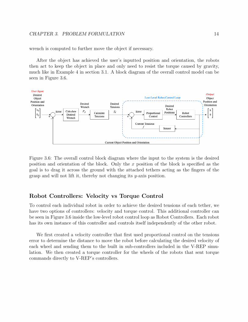
After the object has achieved the user’s inputted position and orientation, the robotsthen act to keep the object in place and only need to resist the torque caused by gravity,much like in Example 4 in section 3.1. A block diagram of the overall control model can beseen in Figure 3.6.
Figure 3.6: The overall control block diagram where the input to the system is the desiredposition and orientation of the block. Only the x position of the block is specified as thegoal is to drag it across the ground with the attached tethers acting as the fingers of thegrasp and will not lift it, thereby not changing its y-axis position.
Robot Controllers: Velocity vs Torque Control
To control each individual robot in order to achieve the desired tensions of each tether, wehave two options of controllers: velocity and torque control. This additional controller canbe seen in Figure 3.6 inside the low-level robot control loop as Robot Controllers. Each robothas its own instance of this controller and controls itself independently of the other robot.
We first created a velocity controller that first used proportional control on the tensionserror to determine the distance to move the robot before calculating the desired velocity ofeach wheel and sending them to the built in sub-controllers included in the V-REP simu-lation. We then created a torque controller for the wheels of the robots that sent torquecommands directly to V-REP’s controllers.

15
Chapter 4
Experiments and Setup
4.1 Simulation
All of the experiments performed and described in this paper were done in the simulationengine V-REP. As there are no simulated tethers or ropes included in V-REP, we createdour own by chaining together spherical joints together with force sensors attached at eachend to measure the tension of the tether. This allowed us to model the flexibility of a tetherand in a later set-up we also added stiff springs to model the small amount of spring force areal tether would exhibit. For the robots, we used V-REP’s included Robotnik Summit XLcar model to act in place of winches that would apply the necessary forces to transform theobject. An image of this simulation can be seen in Figure 4.1.
Bullet vs ODE Physics Engine
To simulate the physics of our system, we had two options: Bullet 2.83 and Open DynamicsEngine (ODE). Both Bullet and ODE are open-source physics engines that can be used tosimulate the physics and dynamics of our V-REP experiments.
Using the setup depicted in Figure 4.1, we tested both physics engines and measured thetensions of the tethers over time. We let the robots drive forward using a default controllerprovided by V-REP until the object was rotated 180 deg and lay on the ground on its side.The results of these measurements can be observed in Figure 4.3.
We observed that Bullet’s results were overall smoother and more consistent than ODE’sresults. Based on these tests, we made the decision to use Bullet 2.83 for our followingexperiments.

CHAPTER 4. EXPERIMENTS AND SETUP 16
Figure 4.1: A screenshot of the first simulation environment set up. A series of sphericaljoints and shapes are chained together to create simulated tethers that are attached to arectangular block object and two wheeled robots. Force sensors measure the tensions of thetwo tethers.
Figure 4.2: A screenshot of the second simulation environment set up. The tethers made ofspherical joints are now also attached to stiff springs.
Robotic Operating System (ROS)
Robotic Operating System (ROS) is an open-source set of software libraries used to buildrobot applications. ROS creates a subscriber-publisher relationship between nodes throughtopics. The publisher will send information to a topic and the subscriber will continuouslyread the topic and run a callback function whenever information is received.

CHAPTER 4. EXPERIMENTS AND SETUP 17
(a) A plot of the tensions vs time using Bullet 2.83.
(b) A plot of the tensions vs time using ODE.
Figure 4.3: Plots comparing the performance of Bullet 2.83 and ODE.
For this project, we used ROS mainly because of its asynchronicity and organization.While V-REP sent all position, tension, and orientation information to the Python backend,

CHAPTER 4. EXPERIMENTS AND SETUP 18
the Python script performed all necessary calculations and sent back the necessary robotvelocities and torques. As we have more than one robot needing to work in parallel, ROS’sasynchonous aspect was useful in controlling all of the robots at once.
4.2 Experiments
To test our control scheme, we tested how well the robots could translate and rotate theobject to a desired position and orientation within a specified tolerance. For the trivialcases, we had the robots move the block by 0.3 meters with no rotation and rotate theobject by -0.5 radians with no translation. For the nontrivial cases, the robots attempted totransform the object to three user-specified positions and orientations. In total, the followingtransformations were applied to the object with both the velocity and torque controllers forthe robots:
• -0.5 radians
• 0.3 meters
• -0.5 radians and 0.3 meters
• -0.6 radians and 0.3 meters
• -0.4 radians and 0.3 meters
A table of necessary conditions and wrenches needed to achieve these different types oftransformations can be found in Table 4.1.

CHAPTER 4. EXPERIMENTS AND SETUP 19
Desired Object Movement Desired Wrench Necessary Conditions
Pure Translation F =
Fx
00
The tension of robot2 must overcome the forceof friction between the object and the groundin order to slide the object to the target posi-tion.
Pure Rotation F =
00τ
The net force applied to the block from thetwo robots along the x-axis must be less thanthe force of friction between the object and theground in order to avoid slipping. The torquecaused by the the robots pulling on the teth-ers also need to be larger than the opposingtorque caused by gravity in order to overcomethe force of gravity and rotate the object.
Rotation and Translation F =
Fx
0τ
The net force on the block along the x-axismust be greater than the resisting force of fric-tion and the torque applied to object must alsobe greater than the torque caused by the forceof gravity in order for the block to both trans-late and rotate.
Table 4.1: Conditions and wrenches needed in order to transform the object by a puretranslation, a pure rotation, and by both a rotation and a translation in the set-up depictedin Figure 4.1.

20
Chapter 5
Results
5.1 Velocity vs Torque Controller Comparison
As discussed in the previous section, we tested our control scheme on three different cases:pure rotation, pure translation, and both rotation and translation with three different setsof target values for the final case. Plots of the object’s position and orientation, the robots’positions, and the desired and actual tensions can be observed below. For the robot con-troller, we tested both a velocity controller and a torque controller. Results for the velocitycontroller experiments can be found in Figures 5.2, 5.3, 5.4, 5.5, and 5.6. Results for thetorque controller experiments can be found in Figures 5.7, 5.8 and 5.9. Videos of some ofthe experiments can be found at https://youtu.be/8aOS7uYwEYE.
While the velocity controller was able to move the object to the desired positions andorientations specified, it struggled with suddenly changing directions when the tension of therobot’s tether was too high or too low and the robot had to reverse directions to remedy thedifference. This problem often presented itself when the robots needed to balance the objectat the goal transformation. The torque controller, on the other hand, exhibited far moreoscillations as it tried to move the object but was able to converge to the goal state muchfaster. In order to help mediate the oscillation problem, we added a derivative component tothe torque controller making it a PD controller compared to the velocity controller’s purelyproportional control. We also observed that the addition of the springs in the tethers wereincreasing the oscillation of the system, making it more difficult for the robots to balancethe object at the goal and so we used the original simulation set-up depicted in Figure 4.1rather than the one in 4.2. We suspect this is most likely due to some unstable dynamicswithin the simulation environment.
Overall, the torque controller can converge to the given goal faster but is less stable, hasmore oscillations, and is more sensitive to errors compared to the velocity controller. Thegreater instability is most likely largely due to torque control being at a lower level than

CHAPTER 5. RESULTS 21
velocity control causing a slower response to disturbances. This increased sensitivity to errorcaused the torque controller to continually over-correct when missing its target, causing itto oscillate about its goal.
Figure 5.1: Images of the V-REP simulation before, during, and after rotating the object by-0.5 radians and translating it by 0.3 meters using the velocity controller.

CHAPTER 5. RESULTS 22
Figure 5.2: Plots of the results of telling the system to rotate the object by -0.5 radians usingthe velocity controller. The first two plots show the calculated desired tensions for the twotether t1 and t2 needed to generate the necessary forces required to move the block from itscurrent position and orientation to its desired one as well as the system’s actual measuredtensions at each time step. The bottom two plots show the block’s change in position andorientation over time as it converges to approximately the desired values.

CHAPTER 5. RESULTS 23
Figure 5.3: Plots of the results of telling the system to move the block object to position0.2 along the x-axis using the velocity controller. Simply pure translation is not possiblewith this simulation as the force of friction between the ground and the entire base of theblock is too high for the robots to overcome so a small rotation of -0.08 rad is also applied tothe object. This very small rotation results in oscillatory behavior once reaching the desiredposition.

CHAPTER 5. RESULTS 24
Figure 5.4: Plots of the results of telling the system to move the block object to position 0.3along the x-axis and rotate it by -0.5 radians using the velocity controller.

CHAPTER 5. RESULTS 25
Figure 5.5: Plots of the results of telling the system to move the block object to position 0.3along the x-axis and rotate it by -0.6 radians using the velocity controller.

CHAPTER 5. RESULTS 26
Figure 5.6: Plots of the results of telling the system to move the block object to position 0.3along the x-axis and rotate it by -0.4 radians using the velocity controller.

CHAPTER 5. RESULTS 27
Figure 5.7: Plots of the results of pure translation of the object by 0.4 m using the torquecontroller. We can observe that the torque controller exhibits far more oscillatory behaviorthan the velocity controller. This is most likely due to a combination of a stick-slip frictionphenomena, causing the robots to repeatedly need to overcome the force of friction betweenthe block and the ground, as well as the torque controller over-correcting each time it missesits goal. The controller over-correcting could most likely be remedied with further tuning.

CHAPTER 5. RESULTS 28
Figure 5.8: A plot of the velocity of the robots and block while translating the block 0.4 musing the torque controller.

CHAPTER 5. RESULTS 29
Figure 5.9: Close up snippets of the block angle, the block and robots’ positions, and theirvelocities as the torque controller translates the block 0.4 m. Although only translation isrequested, the angle of the block oscillates heavily as the block continuously tips back andforth due to the robots over-correcting in each direction.
30
Chapter 6
Discussion and Conclusion
Overall, the results of our experiments were favorable towards our overall goal of performingmanipulation tasks on larger objects using millirobots rather than a large, bilateral armmobile robot that would traditionally be used for such tasks. In most of the tests, the robotswere able to successfully move the object and converge to the desired position and orientation.
While the velocity controller seemed to struggle slightly with reversing the direction ofthe robot when needing less tension on the object or when needing to translate it the oppo-site direction, the torque controller encountered similar problems much less frequently andhad an easier time with such situations.
A limitation of our project, however, is that the object has a limited degree of freedomdue to only having two robots and tethers attached to the block at fixed points. With morerobots, the block could potentially be capable of a wider range of motions. Our model andexperiments also only take two dimensions into account and do not account for three dimen-sional movement. Future work could work to remedy these shortcomings.
Another interesting addition for future work would also be to develop mechanisms forthe robots to be able to attach the tethers to the object themselves at appropriate locationsas well as being able to manipulate objects of various shapes and sizes. Since the massesof our object and each robot were 0.1 kg and 0.16 kg, respectively, the robots were able toproduce enough force to successfully move the object. In order to move objects of greatermass, this set up can be scaled by using more robots to produce more forces or by havingthe robots attach the tethers to winches capable of producing enough tension on the tethersto perform the desired grasp and manipulation.
In conclusion, we have shown that the manipulation of objects that would normallybe performed by large, expensive arm robots can also be executed by small, affordablemillirobots working together or with winches and using tethers to exert the necessary forceson the object to grasp it. Our results have shown that our control scheme and environment set

CHAPTER 6. DISCUSSION AND CONCLUSION 31
up is able to successfully manipulate the object and converge to the target transformation.Further research into this subject could help produce small, affordable robots capable ofmanipulating objects and furniture much larger than them allowing them to assist people intheir homes with household chores and organizational tasks. Such technology could greatlyhelp many people, particularly adults who could then retain their independence when theymight otherwise need constant in-home care.

32
Bibliography
[1] Maya Cakmak and Leila Takayama. “Towards a comprehensive chore list for domesticrobots”. In: 2013 8th ACM/IEEE International Conference on Human-Robot Interac-tion (HRI). 2013, pp. 93–94. doi: 10.1109/HRI.2013.6483517.
[2] David L. Christensen et al. “Let’s All Pull Together: Principles for Sharing LargeLoads in Microrobot Teams”. In: IEEE Robotics and Automation Letters 1.2 (2016),pp. 1089–1096. doi: 10.1109/LRA.2016.2530314.
[3] Matthew A. Estrada et al. “Forceful Manipulation with Micro Air Vehicles”. In: Sci-ence Robotics 3.23 (2018). doi: 10 . 1126 / scirobotics . aau6903. eprint: https :
//robotics.sciencemag.org/content/3/23/eaau6903.full.pdf. url: https://robotics.sciencemag.org/content/3/23/eaau6903.
[4] C. Ferrari and J. Canny. “Planning optimal grasps”. In: Proceedings 1992 IEEE In-ternational Conference on Robotics and Automation. 1992, 2290–2295 vol.3. doi: 10.1109/ROBOT.1992.219918.
[5] Jiaxin L. Fu and Nancy S. Pollard. “On the Importance of Asymmetries in GraspQuality Metrics for Tendon Driven Hands”. In: 2006 IEEE/RSJ International Con-ference on Intelligent Robots and Systems. 2006, pp. 1068–1075. doi: 10.1109/IROS.2006.281812.
[6] Joshua M. Inouye, Jason J. Kutch, and Francisco J. Valero-Cuevas. “A Novel Synthe-sis of Computational Approaches Enables Optimization of Grasp Quality of Tendon-Driven Hands”. In: IEEE Transactions on Robotics 28.4 (2012), pp. 958–966. doi:10.1109/TRO.2012.2196189.
[7] Joshua M. Inouye, Jason J. Kutch, and Francisco J. Valero-Cuevas. “A Novel Synthe-sis of Computational Approaches Enables Optimization of Grasp Quality of Tendon-Driven Hands”. In: IEEE Transactions on Robotics 28.4 (2012), pp. 958–966. doi:10.1109/TRO.2012.2196189.
[8] Cory D. Kidd and Cynthia Breazeal. “Robots at home: Understanding long-termhuman-robot interaction”. In: 2008 IEEE/RSJ International Conference on Intelli-gent Robots and Systems. 2008, pp. 3230–3235. doi: 10.1109/IROS.2008.4651113.

BIBLIOGRAPHY 33
[9] I. Kim and H. Inooka. “Determination of Grasp Forces for Robot Hands Based on Hu-man Capabilities”. In: IFAC Proceedings Volumes 26.2, Part 4 (1993). 12th TriennalWorld Congress of the International Federation of Automatic control. Volume 4 Ap-plications II, Sydney, Australia, 18-23 July, pp. 979–984. issn: 1474-6670. doi: https://doi.org/10.1016/S1474-6670(17)48617-4. url: https://www.sciencedirect.com/science/article/pii/S1474667017486174.
[10] Richard M. Murray, Zexiang Li, and S. Shankar Sastry. A Mathematical Introductionto Robotic Manipulation. 1994.
[11] Taylor Niehues et al. “Cartesian-Space Control and Dextrous Manipulation for Multi-Fingered Tendon-Driven Hand”. In: 2014 IEEE International Conference on Roboticsand Automation (ICRA). 2014, pp. 6777–6783. doi: 10.1109/ICRA.2014.6907860.
[12] Ryuta Ozawa, Kazunori Hashirii, and Hiroaki Kobayashi. “Design and control of un-deractuated tendon-driven mechanisms”. In: 2009 IEEE International Conference onRobotics and Automation. 2009, pp. 1522–1527. doi: 10.1109/ROBOT.2009.5152222.
[13] Hossein Rastgoftar and Ella M. Atkins. “Cooperative aerial lift and manipulation(CALM)”. In: Aerospace Science and Technology 82-83 (2018), pp. 105–118. issn:1270-9638. doi: https://doi.org/10.1016/j.ast.2018.09.005. url: https://www.sciencedirect.com/science/article/pii/S127096381830912X.
[14] Hayley Robinson, Bruce MacDonald, and Elizabeth Broadbent. “The Role of Health-care Robots for Older People at Home: A Review”. In: International Journal of SocialRobotics 6.4 (2014). doi: 10.1007/s12369-014-0242-2. url: https://doi.org/10.1007/s12369-014-0242-2.
[15] D. Rus, B. Donald, and J. Jennings. “Moving furniture with teams of autonomousrobots”. In: Proceedings 1995 IEEE/RSJ International Conference on Intelligent Robotsand Systems. Human Robot Interaction and Cooperative Robots. Vol. 1. 1995, 235–242vol.1. doi: 10.1109/IROS.1995.525802.
[16] Koushil Sreenath and Vijay Kumar. “Dynamics, Control and Planning for CooperativeManipulation of Payloads Suspended by Cables from Multiple Quadrotor Robots”. In:June 2013. doi: 10.15607/RSS.2013.IX.011.
[17] Sean Wilson et al. “Multi-robot Replication of Ant Collective Towing Behaviours”.In: Royal Society Open Science 5.10 (2018). doi: 10.1098/rsos.180409. eprint:https : / / www . ncbi . nlm . nih . gov / pmc / articles / PMC6227946/. url: https :
//www.ncbi.nlm.nih.gov/pmc/articles/PMC6227946/.
[18] Jun Zeng et al. “Differential Flatness Based Path Planning With Direct Collocation onHybrid Modes for a Quadrotor With a Cable-Suspended Payload”. In: IEEE Roboticsand Automation Letters 5.2 (2020), pp. 3074–3081. doi: 10.1109/LRA.2020.2972845.