manhole ordering guide
DESCRIPTION
HDPE Manholes guideTRANSCRIPT
Weh
oM
anh
ole
Ord
erin
g G
uid
e
WehoManholes
WehoManhole Ordering Guide
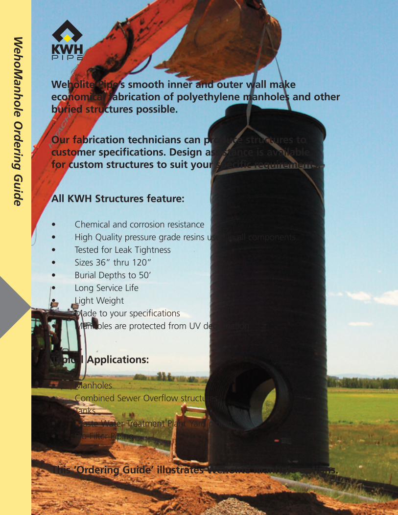
Weholite Pipe’s smooth inner and outer wall make economical fabrication of polyethylene manholes and other buried structures possible.
Our fabrication technicians can produce structures to customer specifications. Design assistance is available for custom structures to suit your specific requirements.
All KWH Structures feature:
• Chemical and corrosion resistance• High Quality pressure grade resins used in all components• Tested for Leak Tightness• Sizes 36” thru 120”• Burial Depths to 50’• Long Service Life• Light Weight• Made to your specifications• Manholes are protected from UV degradation
Typical Applications:
• Manholes• Combined Sewer Overflow structures• Tanks• Waste Water Treatment Plant Yard piping• Bio-Filter Piping
This ‘Ordering Guide’ illustrates Weholite Manhole options.
1
Weh
oM
anh
ole O
rderin
g G
uid
e
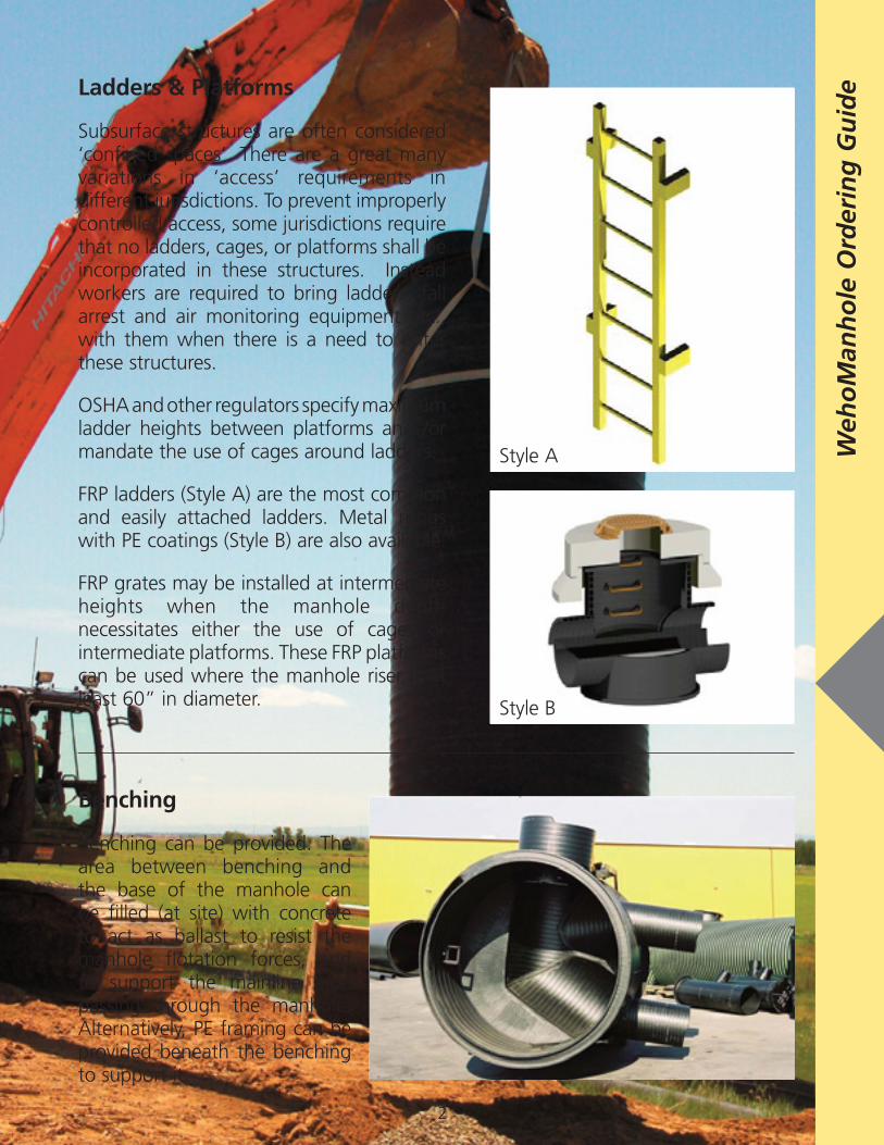
Benching
Benching can be provided. The area between benching and the base of the manhole can be filled (at site) with concrete to act as ballast to resist the manhole flotation forces, and to support the mainline pipe passing through the manhole. Alternatively, PE framing can be provided beneath the benching to support it.
Ladders & Platforms
Subsurface structures are often considered ‘confined spaces’. There are a great many variations in ‘access’ requirements in different jurisdictions. To prevent improperly controlled access, some jurisdictions require that no ladders, cages, or platforms shall be incorporated in these structures. Instead workers are required to bring ladders, fall arrest and air monitoring equipment etc., with them when there is a need to enter these structures.
OSHA and other regulators specify maximum ladder heights between platforms and /or mandate the use of cages around ladders.
FRP ladders (Style A) are the most common and easily attached ladders. Metal rungs with PE coatings (Style B) are also available.
FRP grates may be installed at intermediate heights when the manhole depth necessitates either the use of cages or intermediate platforms. These FRP platforms can be used where the manhole riser is at least 60” in diameter.
Style A
Style B
2
Weh
oM
anh
ole
Ord
erin
g G
uid
e
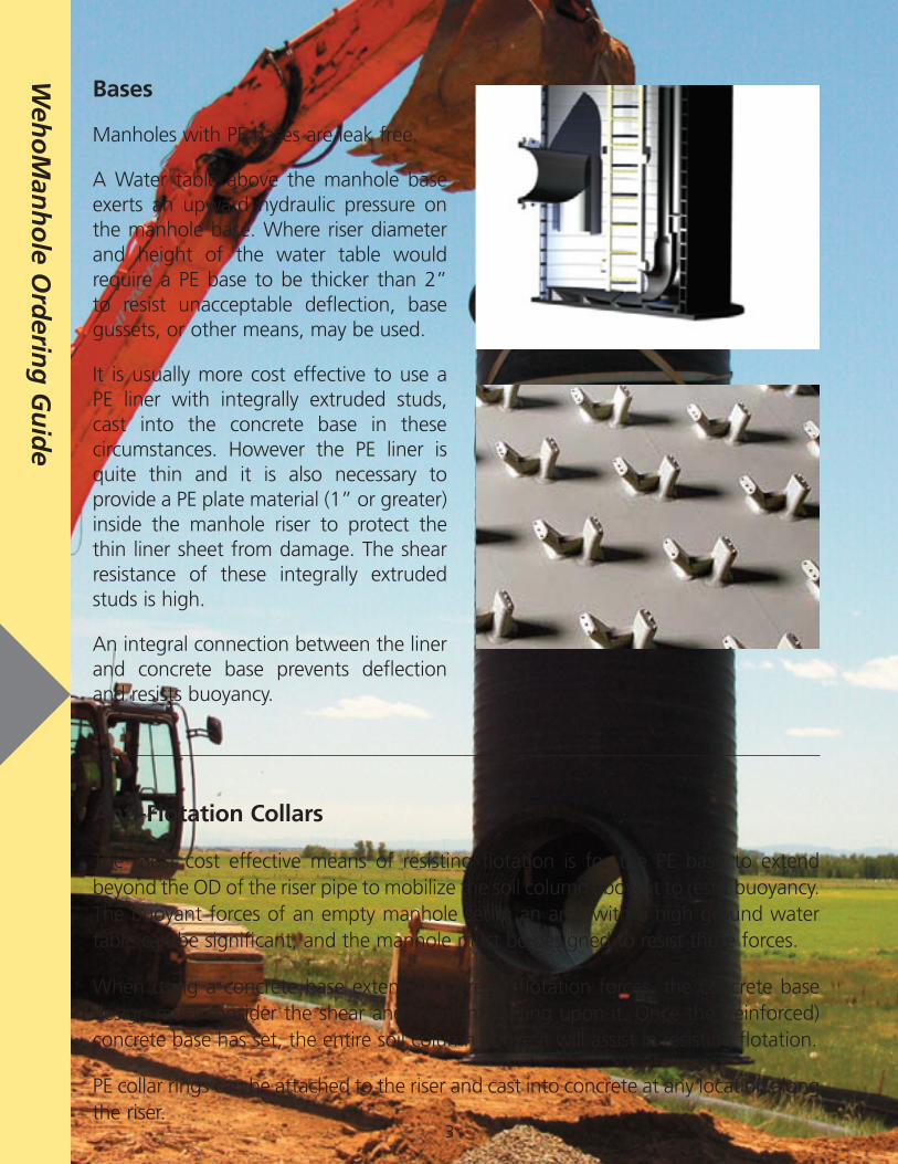
Bases
Manholes with PE bases are leak free.
A Water table above the manhole base exerts an upward hydraulic pressure on the manhole base. Where riser diameter and height of the water table would require a PE base to be thicker than 2” to resist unacceptable deflection, base gussets, or other means, may be used.
It is usually more cost effective to use a PE liner with integrally extruded studs, cast into the concrete base in these circumstances. However the PE liner is quite thin and it is also necessary to provide a PE plate material (1” or greater) inside the manhole riser to protect the thin liner sheet from damage. The shear resistance of these integrally extruded studs is high.
An integral connection between the liner and concrete base prevents deflection and resists buoyancy.
Anti-Flotation Collars
The most cost effective means of resisting flotation is for the PE base to extend beyond the OD of the riser pipe to mobilize the soil column above it to resist buoyancy. The buoyant forces of an empty manhole set in an area with a high ground water table can be significant, and the manhole must be designed to resist these forces.
When using a concrete base extension to resist flotation forces, the concrete base design must consider the shear and moments acting upon it. Once the (reinforced) concrete base has set, the entire soil column above it will assist in resisting flotation.
PE collar rings can be attached to the riser and cast into concrete at any location along the riser.
3
Weh
oM
anh
ole O
rderin
g G
uid
e
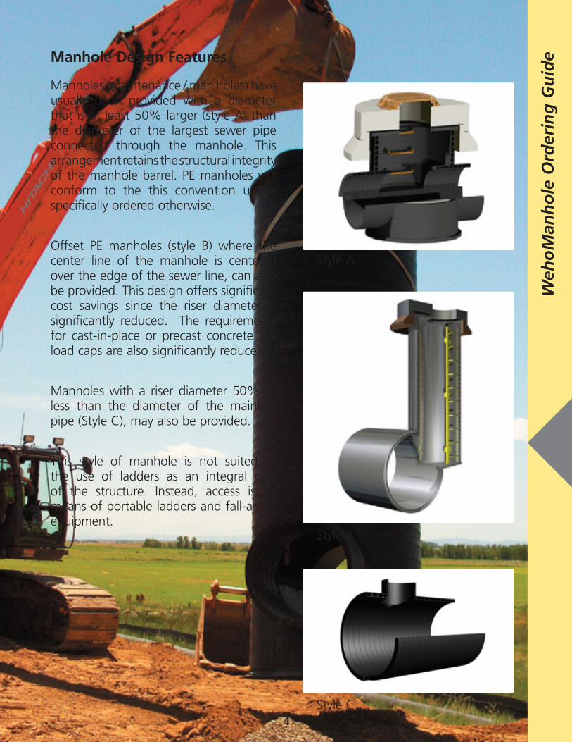
Manhole Design Features
Manholes (maintenance / man holes) have usually been provided with a diameter that is at least 50% larger (style A) than the diameter of the largest sewer pipe connected through the manhole. This arrangement retains the structural integrity of the manhole barrel. PE manholes will conform to the this convention unless specifically ordered otherwise.
Offset PE manholes (style B) where the center line of the manhole is centered over the edge of the sewer line, can also be provided. This design offers significant cost savings since the riser diameter is significantly reduced. The requirements for cast-in-place or precast concrete live load caps are also significantly reduced.
Manholes with a riser diameter 50% or less than the diameter of the mainline pipe (Style C), may also be provided.
This style of manhole is not suited to the use of ladders as an integral part of the structure. Instead, access is by means of portable ladders and fall-arrest equipment.
Style A
Style B
Style C4
Weh
oM
anh
ole
Ord
erin
g G
uid
e
5
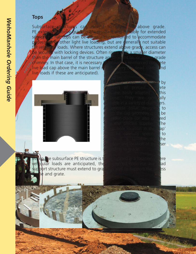
Tops
Subsurface structures can extend to grade or above grade. PE extending above grade is UV resistant and suitable for extended service. PE flat tops can be structurally reinforced to accommodate pedestrian or other light live loading, but are generally not suitable for vehicular loads. Where structures extend above grade, access can be secured with locking devices. Often risers with a smaller diameter than the main barrel of the structure are brought to, or above grade chimney. In that case, it is necessary to provide a reinforced concrete live load cap above the main barrel riser to carry the dead loads (and live loads if these are anticipated).
Live load caps designed by suppliers of precast concrete caps are easily adapted to this purpose. They are generally available in a variety of diameters. A concrete collar designed to match the cap geometry must be poured-in-place (or also ordered from the precast supplier). The access hole location in the ‘cap’ must be carefully specified to ensure it is suitable for the diameter and location of the riser extending to grade.
When the subsurface PE structure is to be located in a location where vehicular loads are anticipated, the reinforced concrete live load support structure must extend to grade as well to support the access frame and grate.
Weh
oM
anh
ole O
rderin
g G
uid
e

Model or GuideSpecification for HDPE Manhole Fabrication
NOTE: Sections 1 thru 8 are general ‘material specifications’. PE manholes should reflect the size and geometry requirements of the project and be designed in accordance with the procedure described in ASTM F1759, in order to satisfy the minimum structural requirements of the manhole. However design of the manhole is beyond the scope of this material supply section. The project specific design of a manhole is dependent on site conditions and on the project specific installation requirements. Sections 9 is a guide or model specifications for the ‘installation’ of the manhole.
SECTION 1 – GENERAL
1.1 SCOPE:
This specification covers the material specifications and fabrication requirements of High Density Polyethylene Manholes in nominal riser sizes of 48” – 120”. The design of PE manholes in accordance with ASTM F1759 - Standard Practice for Design of High Density Polyethylene Manholes in Subsurface Applications is beyond the scope of this specification.
1.2 DEFINITIONS:
1.2.1 Fabricator: The firm responsible for creation of shop drawings, and the accumulation of all components and the execution of the works to create the manhole produced in accordance with this specification and the shop drawings.
1.2.2 Inspector: The authorized representative of the purchaser entrusted with the duty of inspecting the manhole or components used in the fabrication of the manhole, and witnessing tests performed under this specification.
1.2.3 Inspection: Inspection of the components or the complete fabrication, by the inspector.
1.2.4 Manufacturer: The firm producing the riser pipe and stubout pipes.
1.2.5 Purchaser: The person, firm, corporation or government agency engaging in a contract or agreement to purchase a PE fabrication according to this specification.
1.2.6 Riser: The vertical body of the manhole.
1.2.7 Stubout: Short sections of PE pipe that are part of the manhole fabrication that are to be attached to the sewer connections to the manhole in the field.
2.0 REFERENCE SPECIFICATIONS:
ASTM D3350 Standard Specification for Polyethylene Plastic Pipes and Fittings Materials.
ASTM D3261 Standard Specification for Butt Heat Fusion of Polyethylene (PE) Plastic Fittings for Polyethylene (PE) Plastic Pipe and Tubing.
ASTM F714 Standard Specification for Polyethylene (PE) Plastic Pipe (SDR-PR) Based on Outside Diameter.
ASTM F894 Standard Specification for Polyethylene (PE) Large Diameter Profile Wall Sewer and Drain Pipe.
ASTM F1759 Standard Practice for Design of High Density Polyethylene Manholes in Subsurface Applications.
SECTION 3.0 - MATERIALS:
3.1 Base Materials: The riser shaft, top (if applicable), base and stubout pipes shall be made of PE plastic compound meeting the requirement of cell classification PE 334433C or E or higher as defined in ASTM D3350 (latest edition). The riser shaft shall be made of closed profile pipe meeting the requirement of ASTM F894. Stubouts shall meet the requirements of closed profile wall pipe meeting the requirements of ASTM F894 or solid wall pipe meeting the requirements of ASTM F714, as applicable. The Manufacturer shall certify that the materials used to manufacture manholes meet these requirements. PE plate, PE weld extrusion resins (rod or pellets) shall be produced from resin meeting the same cell PE 334433C or E classification as that used to make the pipe components.
3.1 Rework Materials: Clean rework material of the type described in section 3.1 and generated from the manufacturer’s own production, may be used provided that the material is of the same cell classification as the base PE materials and that it allows the manufacturing of manhole risers and stubouts that meet all the requirements of this specification.
3.2 Other Materials: Materials other than those specified under base materials may be used as part of the manhole appurtenances (ladders, grates, etc.). Appurtenance materials shall be as agreed between the Manufacturer and Purchaser.
SECTION 4 – REQUIREMENTS
4.1 Joints & Connections: All joints and connections between PE components shall be made by means of extrusion welding or fusion (butt, or socket) welding. Where fusion is used, it shall meet the requirements of ASTM D3261- Standard Specification for Butt Heat Fusion of Polyethylene (PE) Plastic Fittings for Polyethylene (PE) Plastic Pipe and Tubing. Where extrusion welding is used, it shall be undertaken by joining technicians under the direction of DVS certified extrusion welding trainers.

SECTION 5.0 - MANUFACTURER’S QUALITY CONTROL & INSPECTION REQUIREMENTS
5.1 The manhole fabricator shall be the manufacturer of the pipe used to make the manhole components. The Manufacturer and Fabricator shall have an established quality control program meeting the requirements of ISO 9001:2009. The Fabricator shall have an established quality control program for inspecting incoming of all accessories and all components other than pipe, used in the manhole fabrication.
5.2 The manhole fabrication shall be factory leak tested with air or water to assess the integrity of all joints / connections. The factory test shall be completed in accordance with a documented testing procedure unless otherwise agreed to by the Manufacturer and the Purchaser.
5.3 When the Purchaser so specifies on the purchase order, the testing may be witnessed by the Purchaser’s Inspector. The inspector shall have free access to the inspection area of the manufacturer’s plant.
5.4 The fabricator shall furnish a certificate of compliance to these specifications upon request to do so in the purchase order.
SECTION 6 – SHOP DRAWINGS
6.1 The Manufacturer / Fabricator of the manhole shall prepare shop drawings of the manhole in accordance with the purchaser’s requirements.
6.2.1 Upon request, complete shop drawings of the manholes shall be submitted to the Purchaser or his agent for review and approval.
SECTION 7 – WORKMANSHIP
7.1 The riser and stubout pipes shall be homogenous throughout and free from visible cracks, holes, foreign inclusions or other injurious defects. All dimensions shall comply with the tolerances identified on the approved shop drawings.
SECTION 8 – DELIVERY
8.1 Manholes shall be prepared for standard commercial shipments unless otherwise specified.
Model or Guide
Specification for HDPE Manhole Installation
SECTION 9 – INSTALLATION
9.1 Unloading: Manholes can be unloaded from the truck by using a boom and sling arrangement that places lifting loads on the riser and not on the stubouts.
9.2 Base Installation: Achieve stable and permanent support under and around the manhole. Place and compact base materials. Install the manhole in a dry trench or excavation. Check grades and stubout alignments prior to backfilling or prior to placing concrete as a base or as an anti-flotation ring. When the manhole base design includes HDPE concrete liner plate (Agru Sure-Grip ® or equal), place and level the concrete and lower and work the manhole into the wet concrete before it sets.
9.2 Stubout Connections: Stubouts connections to the sewer pipes may be joined with elastomeric gasketed joints, or joints made with extrusion or butt fusion. Complete all stubout connections prior to backfilling.
9.3 Backfill and Compaction: Place and compact backfill materials as specified on the project drawings. Place and compact materials in lifts, completing each lift around the manhole before proceeding to the next lift. Backfill materials shall be shovel sliced into the haunch area under the stubouts to ensure they are properly placed and compacted.
9.4 Live Load Caps: When the project drawings require life load caps designed to support vehicular or other loads, the cap foundation ring must be placed on the well compacted embedment materials surrounding the manhole riser. The cap itself must be physically separated by several inches, as specified on the project drawings, from the PE manhole riser.

Manhole Definition Select Style (circle one) A B C see Manhole Features Page 2-5 for Illustrations. Elevation Information
Inle
t &
Out
let
Conn
ecti
ons
Nom. Size RSC, DR, or class
Depth to Invert or invert elevation
Orientation (°)Weho, Solid Wall PE, PVC,
etc.Slope
1 0°
2
3
4
Chim
ney
Size RSC, DR, or class
Top of Grate Elev.
Centered or O/S to one
side.
Indicate Mat’l if not Weholite ..eg Solid Wall
PE
<----- Trim here
Notes 1. Indicate units for elevation information (eg. feet / meters) 2. Provide Sketch as needed to clarify orientation etc. 3. The ‘class’ of the riser pipe may be left blank and KWH Pipe will recommend the class as part of a submittal package. 4. Unless fall arrest equipment is used, AASHTO and other regulatory bodies require that ladders exceeding 20’ (6.1m) shall be ‘caged’ or that landing platforms are provided at 20’ (6.1m) and that ladders exceeding 30’ (9.2m) shall have a landing platforms at 30’ regardless of whether or not they are ‘caged’. 5. MH will be assessed for strucutural adequacy per ASTM F1759 based on soil stiffness of 1500psi and embedment backfill compaction placed at minimum uniformity. Design Calculations will be included as part of the drawing submittal package for review and approval by the owner.
Rise
r Size RSC Top of Riser Desired Inv. Elevation Info
Rise
rCo
ver Thickness
Y/N
Benching
FRP Ladder
Ladder Cage (if over 20’ / 6.1m)
Ladder Landing Platform (if over 30’ / 9.2 m)
Anti-Flotation Collar(s)
Lockable Lid (when PE is brought to grade)
Base Design Recommenation by KWH Pipe
Depth of water table below finished grade
Customer comments or notes
Thickness
Base
Deti
als

The accuracy or applicability of all information contained herein is intended as a guide and is not guaranteed. Hence, KWH Pipe assumes no obligation or liability for this information. All tables and statements may be considered as recommendations but not as warranty. Users of our products should perform their own tests to determine the suitability of each such product for their particular purposes. KWH Pipe’s liability for defective products is limited to the replacement, without charge, of any product found to be defective. Under no circumstances shall it be responsible for any damages beyond the price of the products, and in no event shall it be liable for consequential damages.
KWH Pipe6507 Mississauga Road, Mississauga, Ontario, Canada L5N 1A6 Tel.: 905-858-0206 • Fax: 905-858-0208Toll Free: 1-866-KWH-PIPE (594-7473)[email protected] • www.kwhpipe.ca www.weholite.com Printed in Canada.
01/11 L/C
WeholiteVersatile lightweight pipe system for gravity and low-pressure applications