managing network services
TRANSCRIPT
OL-3061-01
C H A P T E R 5
Managing Network ServicesThe Cisco Broadband Access Center (BAC) software enables you to organize and manage network services. Network services are predefined resources that include:
• Authentication, authorization, and accounting (AAA) servers
• Dynamic Host Configuration Protocol (DHCP) servers
• Cisco IE2100 Configuration Engine servers
• Cisco CNS Notification Engine servers
• Terminal servers
• Quality of service (QoS) features, including access lists, class maps, and policy maps.
• Service classes
• Tunnels
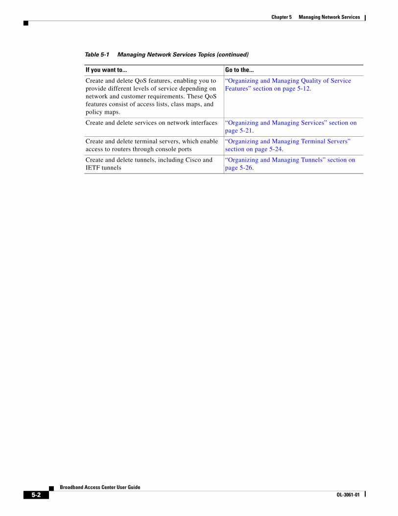
Table 5-1 lists the topics discussed in this chapter and their associated sections.
Table 5-1 Managing Network Services Topics
If you want to... Go to the...
Learn what the network services are “Overview of Network Services” section on page 5-3.
Create and delete AAA servers, including proxy servers
“Organizing and Managing AAA Servers” section on page 5-4.
Create and delete access lists, which enable the filtering of network traffic, including standard and extended access lists
“Organizing and Managing Notification Engine Servers” section on page 5-7.
Create and delete Cisco CNS Notification Engine servers, which enable fault management
“Organizing and Managing Notification Engine Servers” section on page 5-7.
Create and delete Cisco IE2100 Configuration Engine servers, which store and deliver router configurations
“Organizing and Managing Configuration Engine Servers” section on page 5-9.
Create and delete Cisco CNS Network Registrar servers, which enable IP address management through DHCP
“Organizing and Managing DHCP Servers” section on page 5-10.
5-1Broadband Access Center User Guide
Chapter 5 Managing Network Services
Create and delete QoS features, enabling you to provide different levels of service depending on network and customer requirements. These QoS features consist of access lists, class maps, and policy maps.
“Organizing and Managing Quality of Service Features” section on page 5-12.
Create and delete services on network interfaces “Organizing and Managing Services” section on page 5-21.
Create and delete terminal servers, which enable access to routers through console ports
“Organizing and Managing Terminal Servers” section on page 5-24.
Create and delete tunnels, including Cisco and IETF tunnels
“Organizing and Managing Tunnels” section on page 5-26.
Table 5-1 Managing Network Services Topics (continued)
If you want to... Go to the...
5-2Broadband Access Center User Guide
OL-3061-01
Chapter 5 Managing Network ServicesOverview of Network Services
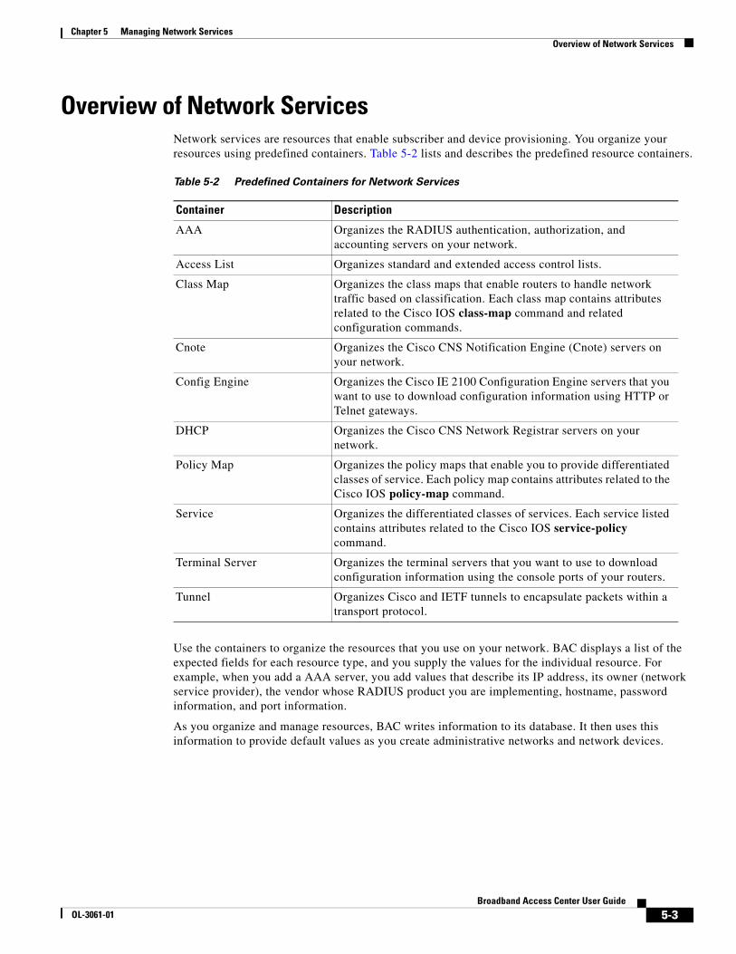
Overview of Network ServicesNetwork services are resources that enable subscriber and device provisioning. You organize your resources using predefined containers. Table 5-2 lists and describes the predefined resource containers.
Use the containers to organize the resources that you use on your network. BAC displays a list of the expected fields for each resource type, and you supply the values for the individual resource. For example, when you add a AAA server, you add values that describe its IP address, its owner (network service provider), the vendor whose RADIUS product you are implementing, hostname, password information, and port information.
As you organize and manage resources, BAC writes information to its database. It then uses this information to provide default values as you create administrative networks and network devices.
Table 5-2 Predefined Containers for Network Services
Container Description
AAA Organizes the RADIUS authentication, authorization, and accounting servers on your network.
Access List Organizes standard and extended access control lists.
Class Map Organizes the class maps that enable routers to handle network traffic based on classification. Each class map contains attributes related to the Cisco IOS class-map command and related configuration commands.
Cnote Organizes the Cisco CNS Notification Engine (Cnote) servers on your network.
Config Engine Organizes the Cisco IE 2100 Configuration Engine servers that you want to use to download configuration information using HTTP or Telnet gateways.
DHCP Organizes the Cisco CNS Network Registrar servers on your network.
Policy Map Organizes the policy maps that enable you to provide differentiated classes of service. Each policy map contains attributes related to the Cisco IOS policy-map command.
Service Organizes the differentiated classes of services. Each service listed contains attributes related to the Cisco IOS service-policy command.
Terminal Server Organizes the terminal servers that you want to use to download configuration information using the console ports of your routers.
Tunnel Organizes Cisco and IETF tunnels to encapsulate packets within a transport protocol.
5-3Broadband Access Center User Guide
OL-3061-01

Chapter 5 Managing Network ServicesOrganizing and Managing AAA Servers
Organizing and Managing AAA ServersAAA servers provide authentication, authorization, and accounting only in LAC, PTA, and LNS broadband aggregation scenarios. AAA (or RADIUS) servers receive subscriber connection requests through a router, which acts as a network access server (NAS). AAA servers authenticate users and return to the NAS the configuration information needed to deliver service to the subscriber.
BAC directly supports either the Cisco CNS Access Registrar server or the Interlink Merit AAA server. You can configure these servers as either remote or proxy servers. You link a proxy server to a remote server. You can add other AAA servers as proxy servers, if you then associate them with an Access Registrar or a Merit server.
About AAA Servers When you create a AAA server, you define the fields listed in Table 5-3.
To Create a AAA ServerCreate a AAA server to support RADIUS proxy configuration. This enables an administrator to configure a AAA server to act as a proxy client to other RADIUS servers or other kinds of authentication servers.
Table 5-3 AAA Server Fields
Field Description
Parent System-supplied value, which is similar to a path statement, that locates the device in the network hierarchy.
IP Address The IP address of an interface on the AAA server. This field is required.
Host Name The UNIX hostname of the server. This field is required.
Host Root Password The password for the user root. This field is required.
AAA Vendor The name of the AAA server vendor: either CAR (CNS Access Registrar), Merit, or Other. This field is required.
Path The installation path for the RADIUS software. This field is required.
Server Login Id The login ID of the Access Registrar server administrator.
Server Login Password The login password of the Access Registrar server administrator.
Authentication Port System-supplied value that specifies the authentication port on the server.
Accounting Port System-supplied valued that specifies the accounting port on the server.
Update AAA A check box that enables the Subscriber Access Manager component of BAC to update the RADIUS server and your database.
Proxy A check box that enables the server to act as a proxy server, passing authentication requests to remote servers. You can define an associated remote server only when the AAA server is created as a proxy.
Description An optional text block for descriptive information about the server.
5-4Broadband Access Center User Guide
OL-3061-01

Chapter 5 Managing Network ServicesOrganizing and Managing AAA Servers
Before you add a AAA server to BAC, determine whether it is a remote server or a proxy server. It does not matter in what order you create the proxy server and the remote server. You link the two servers after you create them. When you are ready, log in to BAC.
To create a AAA server, follow these steps:
Step 1 Click the Network Services tab. The system displays the Network Services Inventory page in the content area of the main window.
Step 2 In the Object Selector, click AAA.
Step 3 In the main window, click Create. The system displays the Select Owners page.
The Select Owners page contains a dual column selection box, which you use to add and remove owners.
Step 4 In the Available Owners list box, choose the owner of the access list and click Add. BAC moves the owner to the Selected Owners list box.
Step 5 Click Next. The system displays the Create AAA page in the main window.
Step 6 Enter the AAA resource information, as defined in Table 5-3.
Note To enable BAC to update the AAA server automatically, check Update AAA. If you disable updates, you must process any updates manually.
To enable the AAA server to act as a proxy, check Proxy.
Step 7 When you are done, click Finish. The system redisplays the Network Services Inventory page in the main window.
Note To view the new AAA server, expand the AAA folder.
Step 8 If you are creating a remote server and a proxy server, repeat Steps 2 through 7 to add another server. Then, go to the “Associating a Proxy Server With a Remote Server” section on page 5-5.
Associating a Proxy Server With a Remote ServerYou can configure a AAA server to act as a proxy server. The proxy server passes authentication requests to a remote server, which might be a AAA server or another type of authentication server; for example, an RSA server. You first use BAC to add both servers, then you create the link between them.
BAC supports two network topologies. In the first topology, the proxy server is located at wholesale network access provider where the BAC server can access it. The remote server is located at the retail service provider and is inaccessible to the BAC server due to a firewall. In this topology, BAC cannot configure the remote server, so the retail service provider must ensure it is configured to support a proxy server.
In the second topology, the proxy server and the remote server are located at the wholesale network access provider. In this topology, BAC configures both servers.
5-5Broadband Access Center User Guide
OL-3061-01

Chapter 5 Managing Network ServicesOrganizing and Managing AAA Servers
About Associating a Proxy ServerWhen you associate a proxy server with a remote server, you define the fields listed in Table 5-4.
To Associate a Proxy Server to a Remote ServerBefore you associate a proxy server with a remote server, be aware of the following considerations:
• Be familiar with the characteristics of Access Registrar and Merit AAA servers; for example, Access Registrar allows one realm across multiple remote servers where Merit only allows one realm to one remote server.
• BAC supports only one level of linking proxy servers to remote servers; that is, you can link a proxy server only to a remote server, even if the proxy server can point to another proxy server.
• A server can function as either a proxy server or as a remote server, but it cannot function in both capacities.
To associate a proxy and a remote server, follow these steps:
Step 1 Click the Network Services tab. The system displays the Network Services Inventory page in the content area of the main window.
Step 2 In the Object Selector, expand the AAA folder and choose the proxy server that you want to associate with a remote server.
Step 3 In the main window, click Associate Proxy. The system displays the AAA Proxy Link Inventory page.
Step 4 Click Add. The system displays the Associate AAA Proxy With a Remote AAA Resource dialog box.
Step 5 Enter the information about the proxy association, as defined in Table 5-4.
Step 6 Click OK. The system redisplays the AAA Proxy Link Inventory page.
Step 7 Click Done.
To Delete a AAA ServerBefore you delete a AAA server, be aware of the following considerations:
• If any subscribers are provisioned using this AAA server, BAC cannot remove the RADIUS service feature from any network devices associated with this AAA server, and you cannot delete the AAA resources.
Table 5-4 Proxy Association Fields
Field Description
Realm The namespace that the proxy server manages. This field is required.
Key The shared secret key that the proxy and remote servers use to authenticate one another. This field is required.
Remote AAA A drop-down list of remote servers.
5-6Broadband Access Center User Guide
OL-3061-01
Chapter 5 Managing Network ServicesOrganizing and Managing Notification Engine Servers
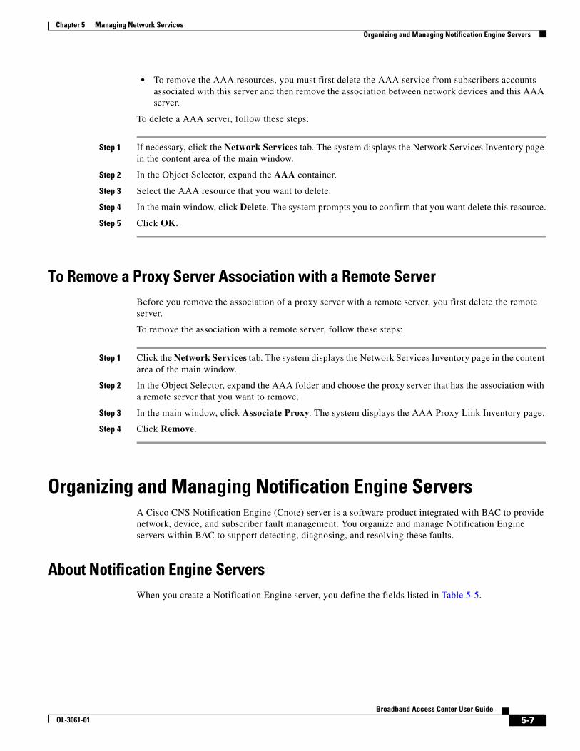
• To remove the AAA resources, you must first delete the AAA service from subscribers accounts associated with this server and then remove the association between network devices and this AAA server.
To delete a AAA server, follow these steps:
Step 1 If necessary, click the Network Services tab. The system displays the Network Services Inventory page in the content area of the main window.
Step 2 In the Object Selector, expand the AAA container.
Step 3 Select the AAA resource that you want to delete.
Step 4 In the main window, click Delete. The system prompts you to confirm that you want delete this resource.
Step 5 Click OK.
To Remove a Proxy Server Association with a Remote ServerBefore you remove the association of a proxy server with a remote server, you first delete the remote server.
To remove the association with a remote server, follow these steps:
Step 1 Click the Network Services tab. The system displays the Network Services Inventory page in the content area of the main window.
Step 2 In the Object Selector, expand the AAA folder and choose the proxy server that has the association with a remote server that you want to remove.
Step 3 In the main window, click Associate Proxy. The system displays the AAA Proxy Link Inventory page.
Step 4 Click Remove.
Organizing and Managing Notification Engine ServersA Cisco CNS Notification Engine (Cnote) server is a software product integrated with BAC to provide network, device, and subscriber fault management. You organize and manage Notification Engine servers within BAC to support detecting, diagnosing, and resolving these faults.
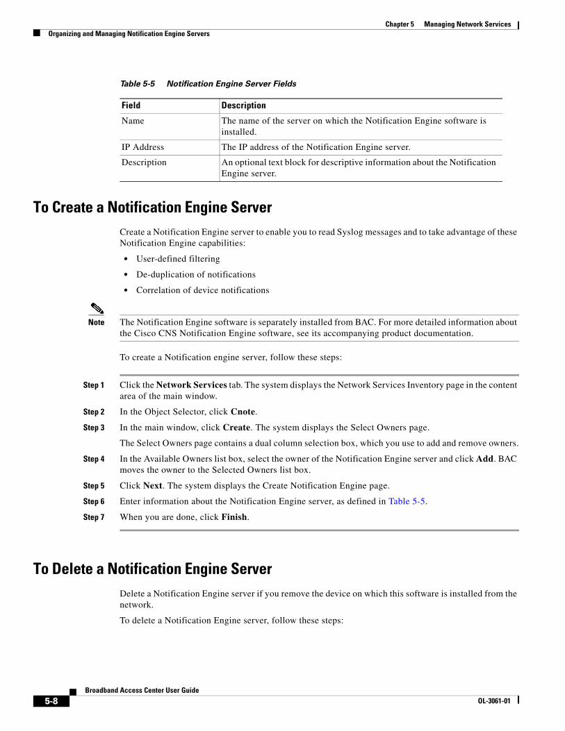
About Notification Engine Servers When you create a Notification Engine server, you define the fields listed in Table 5-5.
5-7Broadband Access Center User Guide
OL-3061-01
Chapter 5 Managing Network ServicesOrganizing and Managing Notification Engine Servers
To Create a Notification Engine ServerCreate a Notification Engine server to enable you to read Syslog messages and to take advantage of these Notification Engine capabilities:
• User-defined filtering
• De-duplication of notifications
• Correlation of device notifications
Note The Notification Engine software is separately installed from BAC. For more detailed information about the Cisco CNS Notification Engine software, see its accompanying product documentation.
To create a Notification engine server, follow these steps:
Step 1 Click the Network Services tab. The system displays the Network Services Inventory page in the content area of the main window.
Step 2 In the Object Selector, click Cnote.
Step 3 In the main window, click Create. The system displays the Select Owners page.
The Select Owners page contains a dual column selection box, which you use to add and remove owners.
Step 4 In the Available Owners list box, select the owner of the Notification Engine server and click Add. BAC moves the owner to the Selected Owners list box.
Step 5 Click Next. The system displays the Create Notification Engine page.
Step 6 Enter information about the Notification Engine server, as defined in Table 5-5.
Step 7 When you are done, click Finish.
To Delete a Notification Engine ServerDelete a Notification Engine server if you remove the device on which this software is installed from the network.
To delete a Notification Engine server, follow these steps:
Table 5-5 Notification Engine Server Fields
Field Description
Name The name of the server on which the Notification Engine software is installed.
IP Address The IP address of the Notification Engine server.
Description An optional text block for descriptive information about the Notification Engine server.
5-8Broadband Access Center User Guide
OL-3061-01

Chapter 5 Managing Network ServicesOrganizing and Managing Configuration Engine Servers
Step 1 If necessary, click the Network Services tab. The system displays the Network Services Inventory page in the content area of the main window.
Step 2 In the Object Selector, expand the Cnote container.
Step 3 Select the Notification Engine server that you want to delete.
Step 4 In the main window, click Delete. The system prompts you to confirm that you want delete this resource.
Step 5 Click OK.
Organizing and Managing Configuration Engine ServersYou organize and manage Configuration Engine servers to handle groups of Cisco IOS devices and the services they deliver. These servers store router configurations and deliver them to devices as needed.
About Configuration Engine ServersWhen you create Configuration Engine servers, you define the fields listed in Table 5-6.
Table 5-6 Configuration Engine Server Fields
Field Description
Parent A system-supplied value, which is similar to a path statement, that locates the server in the network hierarchy.
Name The name of the Configuration Engine server.
Type The method that you want to use to download configuration files. The values are:
• Telnet/Console—Choose this option to download using Telnet or the console port. Telnet establishes a session with a router. Console establishes a Telnet session with a terminal server to download over the console port of the router.
• HTTP—Choose this option to download using the hypertext transfer protocol (HTTP). BAC uses the CNS Agent to download files using HTTP.
CDM Index Indicates the server used in downloading configuration files. The value that you enter has the following form:
IE2100_numericvalue
For example, IE2100_0 might be used for a Telnet/Console server.
The values in this field are set in the cdm.properties file, which is located in $BAC_HOME/cdm/properties/. You add and remove Telnet/Console and HTTP servers using this file. For information about modifying this file, see the Broadband Access Center Installation and Configuration Guide.
5-9Broadband Access Center User Guide
OL-3061-01

Chapter 5 Managing Network ServicesOrganizing and Managing DHCP Servers
To Create a Configuration Engine ServerCreate a Configuration Engine server if you want to download the configuration files using Telnet or HTTP.
To create a Configuration Engine server, follow these steps:
Step 1 Click the Network Services tab. The system displays the Network Services Inventory page in the content area of the main window.
Step 2 In the Object Selector, click Config Engine.
Step 3 In the main window, click Create. The system displays the Configuration Engine page.
Step 4 Enter information about the Configuration Engine server, as defined in Table 5-6.
Step 5 When you are done, click OK.
To Delete a Configuration Engine ServerDelete a Configuration Engine server if you remove the device on which this software is installed from the network.
To delete a Configuration Engine server, follow these steps:
Step 1 If necessary, click the Network Services tab. The system displays the Network Services Inventory page in the content area of the main window.
Step 2 In the Object Selector, expand the Configuration Engine container.
Step 3 Select the Configuration Engine server that you want to delete.
Step 4 In the main window, click Delete. The system prompts you to confirm that you want delete this resource.
Step 5 Click OK.
Organizing and Managing DHCP ServersYou organize and manage Cisco CNS Network Registrar servers to provide IP address management and DNS domain update functions.
IP Address The IP address of the server.
Description An optional text block for descriptive information about the server.
Table 5-6 Configuration Engine Server Fields (continued)
Field Description
5-10Broadband Access Center User Guide
OL-3061-01

Chapter 5 Managing Network ServicesOrganizing and Managing DHCP Servers
About DHCP ServersWhen you create a DHCP server, you define the fields listed in Table 5-7.
To Create a DHCP ServerCreate DHCP servers to manage scopes of IP addresses in PTA and LNS broadband aggregation scenarios.
To create a DHCP server, follow these steps:
Step 1 Click the Network Services tab. The system displays the Network Service Inventory page in the content area of the main window.
Step 2 In the Object Selector, click DHCP.
Step 3 In the main window, click Create. The system displays the DHCP page in the main window.
Step 4 Enter the DHCP resource information, as defined in Table 5-7.
Step 5 When you are done, click Finish.
To Delete a DHCP ServerDelete a DHCP server if you remove the device on which this software is installed from the network. To delete a DHCP server, follow these steps:
Step 1 If necessary, click the Network Services tab. The system displays the Network Services Inventory page in contents area of the main window.
Step 2 In the Object Selector, expand the DHCP container.
Step 3 Select the DHCP server that you want to delete.
Step 4 In the main window, click Delete. The system prompts you to confirm that you want delete this resource.
Step 5 Click OK.
Table 5-7 DHCP Server Fields
Field Description
Parent A system-supplied value, which is similar to a path statement, that locates the device in the network hierarchy.
Name A name associated with the DHCP server, not necessarily its hostname.
IP/Hostname The IP address or hostname of the server.
Description An optional text box for descriptive information about the server.
5-11Broadband Access Center User Guide
OL-3061-01

Chapter 5 Managing Network ServicesOrganizing and Managing Quality of Service Features
Organizing and Managing Quality of Service FeaturesYou organize and manage QoS features in BAC so that you can provided differentiated services based on subscriber and network requirements. You control QoS within BAC through:
• Standard access lists
• Extended access lists
• Class maps
• Policy maps
Creating and Managing Standard Access ListsStandard access lists filter IP traffic at a router interface. They permit or deny network access to packets based on conditions you specify in each list.
Tip Create access lists before you create class maps and policy maps.
About Standard Access Lists
When you create a standard access list, you define the fields listed in Table 5-8.
Table 5-8 Standard Access List Fields
Field Description
Access List Name The name or number of the access list. To create an access list that filters IP traffic on an interface, use either a number or a name. To create an access list that filters the traffic of non-IP protocols (for example IPX), use a number. This field is required on the Access List Resource page.
IP Based Indicates whether this is an IP-based filter or not. Values are true or false. This field is required on the Access List Resource page.
Mode Indicates whether this is a standard or extended access list. This field is required on the Access List Resource page.
Description An optional text block for descriptive information about the access list.
5-12Broadband Access Center User Guide
OL-3061-01

Chapter 5 Managing Network ServicesOrganizing and Managing Quality of Service Features
To Create Standard Access Lists
Create standard access lists to filter network traffic based on the source of packets. Before you add a standard access list, be aware of the following considerations:
• You can name or number a standard IP access list. If you number the access list, the number must be in the 1 to 99 range or the 1300 to 1999 range.
• You can only number non-IP standard access lists. The number cannot fall in the 1 to 99 and 1300 to 1999 ranges, or the 100 to 199 and 2000 to 2699 ranges, which are reserved for IP extended access lists.
• A standard IP access list supports multiple permit and deny operations.
• Non-IP standard access lists support only a single permit or deny operation.
To create a standard access list, follow these steps:
Step 1 Click the Network Services tab. The system displays the Network Services Inventory page in the content area of the main window.
Step 2 In the Object Selector, expand the QoS container and click AccessList.
Step 3 In the main window, click Create. The system displays the Select Owners page in the main window.
The Select Owners page contains a dual column selection box, which you use to add and remove owners.
Step 4 In the Available Owners list box, choose the owner of the access list and click Add. BAC moves the owner to the Selected Owners list box.
Step 5 Click Next. The system displays the Select Configuration Profile page.
Step 6 In the Access List folder, select the Access List icon and click Next. The system displays the Access List Resource page.
Operation Specifies whether the filter permits or denies traffic and appears on the Create Access List Resource dialog box.
Values are permit or deny. Select permit to enable a router to handle packets from a host or select deny to prohibit a router from handling packets from a host.
IP Wildcard Bits Identifies one or more addresses for the permit/deny operation and appears on the Create Access List Resource dialog box. Enter one of the following values:
• a valid wildcard mask; for example, 0.0.15.255
• either the keyword any or the keyword host (adding either the hostname or its IP address)
Note Since this is a text field, there is no restriction on the values that you might enter. For example, to configure “access-list 12 deny ip any any log,” enter this string:
any any log
Table 5-8 Standard Access List Fields (continued)
Field Description
5-13Broadband Access Center User Guide
OL-3061-01

Chapter 5 Managing Network ServicesOrganizing and Managing Quality of Service Features
Step 7 Create the access list by entering information in the Access List Name, IP Based, and Mode fields, as defined in Table 5-8.
Step 8 Click Add. The system displays the Create AccessList Resource dialog box.
Step 9 Configure the access list by entering information in the Operation and IP Wildcard Bits fields, as defined in Table 5-8.
Step 10 Click OK. The system redisplays the AccessList Resource page.
Step 11 Click Finish.
To Delete Standard Access Lists
Delete standard access lists access lists if changes to network topology make them obsolete. Before you delete a standard access list, be aware of the following considerateness:
• If any class map or network device references this access list, BAC cannot remove the list.
• To remove the access list:
– Delete the class maps that reference it. You also must delete any policy maps that reference the class maps and any services that reference the policy map.
– Remove references to the access list on network devices.
To delete a standard access list, follow these steps:
Step 1 If necessary, click the Network Services tab. The system displays the Network Services Inventory page in the content area of the main window.
Step 2 In the Object Selector, expand the QoS and Access List containers.
Step 3 Select the access list that you want to delete.
Step 4 In the main window, click Delete. The system prompts you to confirm that you want delete this resource.
Step 5 Click OK.
Creating and Managing Extended Access ListsExtended access lists enable you to filter network traffic based on interfaces, protocols, and source and destination addresses.
About Extended Access Lists
When you create an extended access list, you define the fields listed in Table 5-9.
5-14Broadband Access Center User Guide
OL-3061-01

Chapter 5 Managing Network ServicesOrganizing and Managing Quality of Service Features
To Create Extended Access Lists
Create extended access lists if you want to achieve a greater degree of control over traffic filtering than standard access lists enable. Before you add an extended access list, be aware of the following considerations:
• You can name or number an extended IP access list. If you number the access list, the number must be in the 100 to 199 range or the 2000 to 2699 range.
Table 5-9 Extended Access List Fields
Field Description
Access List Name The name or number of the access list. To create an access list that filters IP traffic on an interface, use either a number or a name. To create an access list that filters the traffic of non-IP protocols (for example IPX), use a number. This field is required on the Access List Resource page.
IP Based Indicates whether this is an IP-based filter or not. Values are true or false. This field is required on the Access List Resource page.
Mode Indicates whether this is a standard or extended access list. This field is required on the Access List Resource page.
Description An optional text block for descriptive information about the access list.
Operation Specifies whether the filter permits or denies traffic nd appears on the Create Access List Resource dialog box. Values are permit or deny.
Protocol Specifies what routed or routing protocol to include in the filter and appears on the Create Access List Resource dialog box.
Source IP Wildcards Identifies one or more source addresses for the permit/deny operation and appears on the Create Access List Resource dialog box.
Enter one of the following values:
• a valid wildcard mask; for example, 0.0.15.255
• either the keyword any or the keyword host (adding either the hostname or its IP address)
Note Since this is a text field, there is no restriction on the values that you might enter. For example, to configure “access-list 12 deny ip any any log,” enter this string:
any any log
Destination IP Wildcards Identifies one or more destination addresses for the permit/deny operation and appears on the Create Access List Resource dialog box.
Enter one of the following values:
• a valid wildcard mask; for example, 0.0.15.255
• either the keyword any or the keyword host (adding either the hostname or its IP address)
Note Since this is a text field, there is no restriction on the values that you might enter. For example, to configure “access-list 12 deny ip any any log,” enter this string:
any any log
5-15Broadband Access Center User Guide
OL-3061-01
Chapter 5 Managing Network ServicesOrganizing and Managing Quality of Service Features
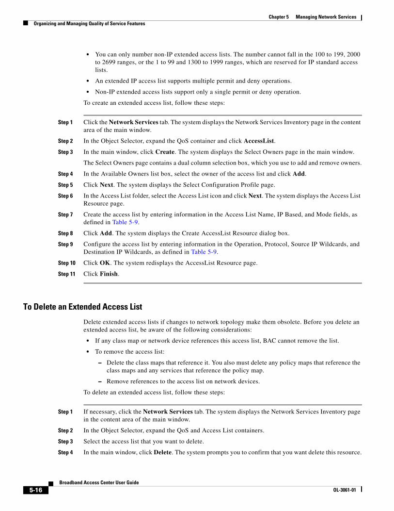
• You can only number non-IP extended access lists. The number cannot fall in the 100 to 199, 2000 to 2699 ranges, or the 1 to 99 and 1300 to 1999 ranges, which are reserved for IP standard access lists.
• An extended IP access list supports multiple permit and deny operations.
• Non-IP extended access lists support only a single permit or deny operation.
To create an extended access list, follow these steps:
Step 1 Click the Network Services tab. The system displays the Network Services Inventory page in the content area of the main window.
Step 2 In the Object Selector, expand the QoS container and click AccessList.
Step 3 In the main window, click Create. The system displays the Select Owners page in the main window.
The Select Owners page contains a dual column selection box, which you use to add and remove owners.
Step 4 In the Available Owners list box, select the owner of the access list and click Add.
Step 5 Click Next. The system displays the Select Configuration Profile page.
Step 6 In the Access List folder, select the Access List icon and click Next. The system displays the Access List Resource page.
Step 7 Create the access list by entering information in the Access List Name, IP Based, and Mode fields, as defined in Table 5-9.
Step 8 Click Add. The system displays the Create AccessList Resource dialog box.
Step 9 Configure the access list by entering information in the Operation, Protocol, Source IP Wildcards, and Destination IP Wildcards, as defined in Table 5-9.
Step 10 Click OK. The system redisplays the AccessList Resource page.
Step 11 Click Finish.
To Delete an Extended Access List
Delete extended access lists if changes to network topology make them obsolete. Before you delete an extended access list, be aware of the following considerations:
• If any class map or network device references this access list, BAC cannot remove the list.
• To remove the access list:
– Delete the class maps that reference it. You also must delete any policy maps that reference the class maps and any services that reference the policy map.
– Remove references to the access list on network devices.
To delete an extended access list, follow these steps:
Step 1 If necessary, click the Network Services tab. The system displays the Network Services Inventory page in the content area of the main window.
Step 2 In the Object Selector, expand the QoS and Access List containers.
Step 3 Select the access list that you want to delete.
Step 4 In the main window, click Delete. The system prompts you to confirm that you want delete this resource.
5-16Broadband Access Center User Guide
OL-3061-01

Chapter 5 Managing Network ServicesOrganizing and Managing Quality of Service Features
Step 5 Click OK.
Creating and Managing Class MapsClass maps define the criteria that enable routers to differentiate network traffic. A class map classifies traffic on an inbound or an outbound interface. You organize and manage class maps to differentiate network traffic based on a series of match criteria.
Tip Create class maps before you create policy maps.
About Class Maps
When you create a class map, you define the fields listed in Table 5-10.
To Create a Class Map
Create class maps to mark IP packets so that routers on your network can evaluate the packets against the match criteria you specify.
Table 5-10 Class Map Fields
Field Description
Class Map Name The name of the class map that defines a traffic class.
Match Type Specifies how to evaluate IP packets. The evaluation criteria is match-any or match-all.
Description An optional text block for descriptive information about the class map.
IP Precedence Two fields that determine whether IP precedence is one of the match criteria. The first field acts as a switch to turn IP precedence on or off. The second field sets the precedence level.
IP DSCP Two fields that determine whether an IP differentiated services code point (DSCP) is one of the match criteria. The first field acts as a switch to turn IP DSCP on or off. The second field defines the code point.
Access Group One of two fields that determine whether an access list is one of the match criteria. Access Group acts as a switch to turn Access Group List on or off.
Access Group List One of two fields that determine whether an access list is one of the match criteria. Access Group List field is a drop-down list box that displays the numbers or names of the standard and extended access lists that you have created. For more information about access lists, see “Creating and Managing Standard Access Lists” section on page 5-12 and “Creating and Managing Extended Access Lists” section on page 5-14.
5-17Broadband Access Center User Guide
OL-3061-01
Chapter 5 Managing Network ServicesOrganizing and Managing Quality of Service Features
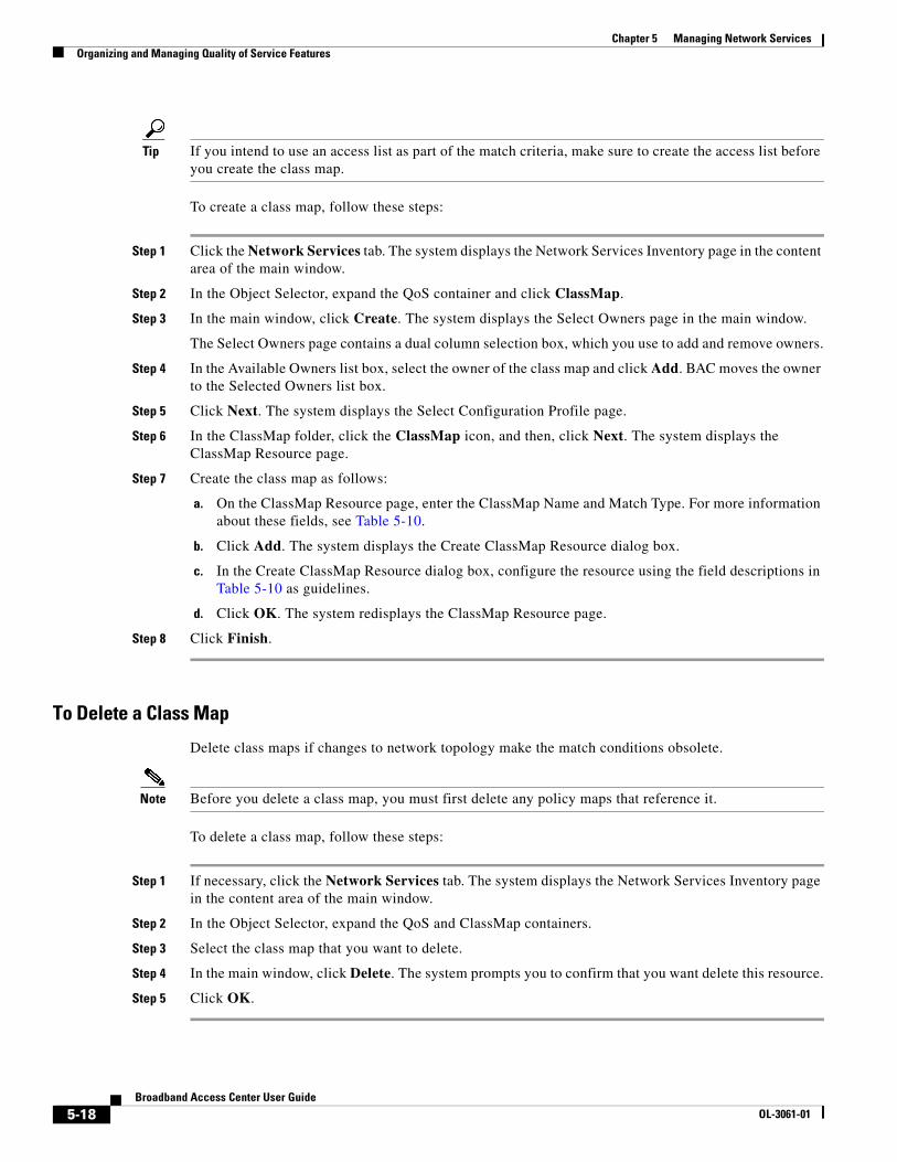
Tip If you intend to use an access list as part of the match criteria, make sure to create the access list before you create the class map.
To create a class map, follow these steps:
Step 1 Click the Network Services tab. The system displays the Network Services Inventory page in the content area of the main window.
Step 2 In the Object Selector, expand the QoS container and click ClassMap.
Step 3 In the main window, click Create. The system displays the Select Owners page in the main window.
The Select Owners page contains a dual column selection box, which you use to add and remove owners.
Step 4 In the Available Owners list box, select the owner of the class map and click Add. BAC moves the owner to the Selected Owners list box.
Step 5 Click Next. The system displays the Select Configuration Profile page.
Step 6 In the ClassMap folder, click the ClassMap icon, and then, click Next. The system displays the ClassMap Resource page.
Step 7 Create the class map as follows:
a. On the ClassMap Resource page, enter the ClassMap Name and Match Type. For more information about these fields, see Table 5-10.
b. Click Add. The system displays the Create ClassMap Resource dialog box.
c. In the Create ClassMap Resource dialog box, configure the resource using the field descriptions in Table 5-10 as guidelines.
d. Click OK. The system redisplays the ClassMap Resource page.
Step 8 Click Finish.
To Delete a Class Map
Delete class maps if changes to network topology make the match conditions obsolete.
Note Before you delete a class map, you must first delete any policy maps that reference it.
To delete a class map, follow these steps:
Step 1 If necessary, click the Network Services tab. The system displays the Network Services Inventory page in the content area of the main window.
Step 2 In the Object Selector, expand the QoS and ClassMap containers.
Step 3 Select the class map that you want to delete.
Step 4 In the main window, click Delete. The system prompts you to confirm that you want delete this resource.
Step 5 Click OK.
5-18Broadband Access Center User Guide
OL-3061-01

Chapter 5 Managing Network ServicesOrganizing and Managing Quality of Service Features
Creating and Managing Policy MapsPolicy maps define QoS actions and rules and associate these to a class maps. You organize and manage policy maps in BAC to set up such things as class-based weighted fair queuing, traffic policing, and traffic shaping.
Tip Create a policy map before you create a service.
About Policy Maps
When you create a policy map, you define the fields Listed in Table 5-7.
Table 5-11 Policy Map Fields
Field Description
Class Map Name The name of the class map to include in the policy map.
Bandwidth Determines whether to enable class-based weighted fair queuing (CBWFQ). This queuing method allows you to define traffic classes and apply bandwidth limits to these classes. The bandwidth you assign to a class is used to calculate the weight of that class. The weight of each packet that matches the class criteria is also calculated from this.
The value is true or false. If you enable bandwidth, you do not need to enable Police.
Bandwidth Type The field that specifies how to limit bandwidth. You can choose to limit based on kilobytes per second (KBPS), a percent of available bandwidth, or the percent of bandwidth remaining.
Bandwidth Value The amount or percent of bandwidth based upon the value you chose for Bandwidth Type.
Police The field that determines whether traffic policing controls the rate of traffic sent or received on an interface. Traffic policing is often configured on interfaces at the edge of a network to limit traffic into or out of the network.
The value is true or false. If you enable Police, you do not need to enable Bandwidth.
Average bps The average bits per second.
Conform Burst The conform burst size (bc) used for policing network traffic. Specify the conform burst size value in bytes as a number from 1,000 to 512,000,000.
Excess Burst The excess burst size (be) for policing network traffic.
Conform Action The action to take on packets that conform to the committed information rate (CIR) and peak information rate (PIR). The default action is to transmit the packet.
Exceed Action The action to take on packets that conform to the PIR but not the CIR. The default action is to drop the packet.
5-19Broadband Access Center User Guide
OL-3061-01
Chapter 5 Managing Network ServicesOrganizing and Managing Quality of Service Features
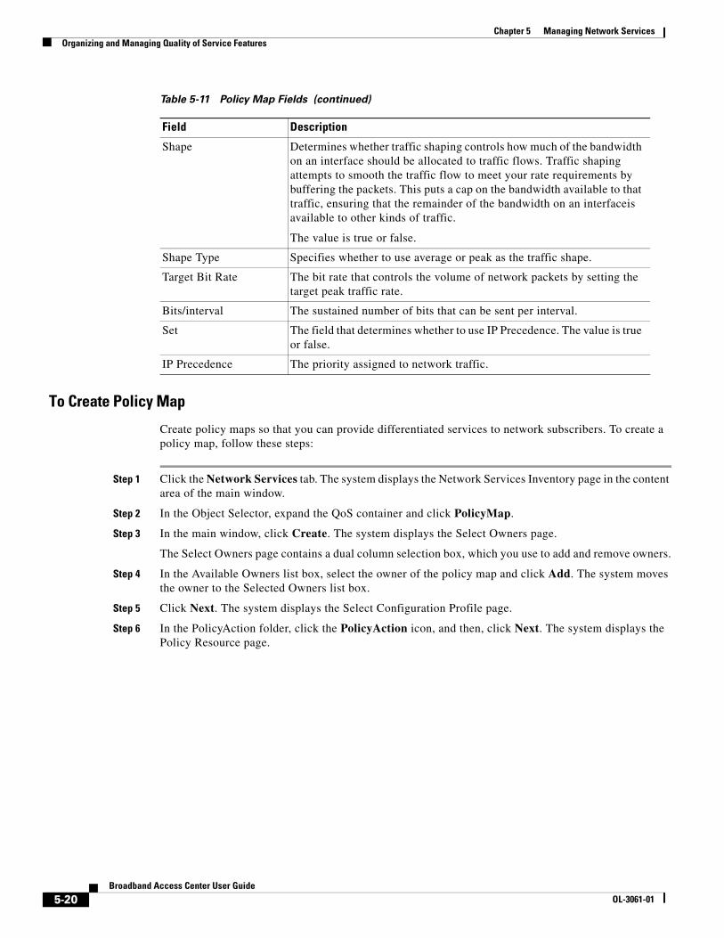
To Create Policy Map
Create policy maps so that you can provide differentiated services to network subscribers. To create a policy map, follow these steps:
Step 1 Click the Network Services tab. The system displays the Network Services Inventory page in the content area of the main window.
Step 2 In the Object Selector, expand the QoS container and click PolicyMap.
Step 3 In the main window, click Create. The system displays the Select Owners page.
The Select Owners page contains a dual column selection box, which you use to add and remove owners.
Step 4 In the Available Owners list box, select the owner of the policy map and click Add. The system moves the owner to the Selected Owners list box.
Step 5 Click Next. The system displays the Select Configuration Profile page.
Step 6 In the PolicyAction folder, click the PolicyAction icon, and then, click Next. The system displays the Policy Resource page.
Shape Determines whether traffic shaping controls how much of the bandwidth on an interface should be allocated to traffic flows. Traffic shaping attempts to smooth the traffic flow to meet your rate requirements by buffering the packets. This puts a cap on the bandwidth available to that traffic, ensuring that the remainder of the bandwidth on an interfaceis available to other kinds of traffic.
The value is true or false.
Shape Type Specifies whether to use average or peak as the traffic shape.
Target Bit Rate The bit rate that controls the volume of network packets by setting the target peak traffic rate.
Bits/interval The sustained number of bits that can be sent per interval.
Set The field that determines whether to use IP Precedence. The value is true or false.
IP Precedence The priority assigned to network traffic.
Table 5-11 Policy Map Fields (continued)
Field Description
5-20Broadband Access Center User Guide
OL-3061-01

Chapter 5 Managing Network ServicesOrganizing and Managing Services
Step 7 Create the policy map as follows:
a. On the Policy Resource page, enter the following information:
– In the PolicyMap Name text box, enter the name of the policy map.
– In the Description text box, enter additional descriptive information about the policy map as desired.
b. Click Add. The system displays the Policy Resource dialog box.
c. In the Create Policy Resource dialog box, enter the policy map resource information, as defined in Table 5-11.
d. When you are done, Click OK. The system redisplays the Policy Resource page.
Step 8 Click Finish.
To Delete Policy Maps
Delete policy maps if network changes make them obsolete.
Note Before you delete a policy map, you must first delete any service or device that references it.
To delete a policy map, follow these steps:
Step 1 If necessary, click the Network Services tab. The system displays the Network Services Inventory page in the content area of the main window.
Step 2 In the Object Selector, expand the Qos and PolicyMap containers.
Step 3 Select the policy map that you want to delete.
Step 4 In the main window, click Delete. The system prompts you to confirm that you want delete this resource.
Step 5 Click OK.
Organizing and Managing ServicesA service attaches a policy map to an interface and specifies the direction (inbound or outbound) to which it applies. You organize and manage services within BAC so that you can provide differentiated services to subscribers depending on their application requirements.
About ServicesWhen you create a service, you define the fields listed in Table 5-12.
5-21Broadband Access Center User Guide
OL-3061-01
Chapter 5 Managing Network ServicesOrganizing and Managing Services
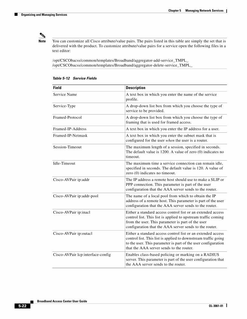
Note You can customize all Cisco attribute/value pairs. The pairs listed in this table are simply the set that is delivered with the product. To customize attribute/value pairs for a service open the following files in a text editor:
/opt/CSCObacss/common/templates/Broadband/aggregator-add-service_TMPL_ /opt/CSCObacss/common/templates/Broadband/aggregator-delete-service_TMPL_
Table 5-12 Service Fields
Field Description
Service Name A text box in which you enter the name of the service profile.
Service-Type A drop-down list box from which you choose the type of service to be provided.
Framed-Protocol A drop-down list box from which you choose the type of framing that is used for framed access.
Framed-IP-Address A text box in which you enter the IP address for a user.
Framed-IP-Netmask A text box in which you enter the subnet mask that is configured for the user when the user is a router.
Session-Timeout The maximum length of a session, specified in seconds. The default value is 1200. A value of zero (0) indicates no timeout.
Idle-Timeout The maximum time a service connection can remain idle, specified in seconds. The default value is 120. A value of zero (0) indicates no timeout.
Cisco-AVPair ip:addr The IP address a remote host should use to make a SLIP or PPP connection. This parameter is part of the user configuration that the AAA server sends to the router.
Cisco-AVPair ip:addr-pool The name of a local pool from which to obtain the IP address of a remote host. This parameter is part of the user configuration that the AAA server sends to the router.
Cisco-AVPair ip:inacl Either a standard access control list or an extended access control list. This list is applied to upstream traffic coming from the user. This parameter is part of the user configuration that the AAA server sends to the router.
Cisco-AVPair ip:outacl Either a standard access control list or an extended access control list. This list is applied to downstream traffic going to the user. This parameter is part of the user configuration that the AAA server sends to the router.
Cisco-AVPair lcp:interface-config Enables class-based policing or marking on a RADIUS server. This parameter is part of the user configuration that the AAA server sends to the router.
5-22Broadband Access Center User Guide
OL-3061-01
Chapter 5 Managing Network ServicesOrganizing and Managing Services
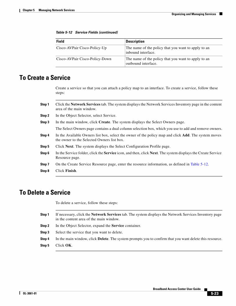
To Create a ServiceCreate a service so that you can attach a policy map to an interface. To create a service, follow these steps:
Step 1 Click the Network Services tab. The system displays the Network Services Inventory page in the content area of the main window.
Step 2 In the Object Selector, select Service.
Step 3 In the main window, click Create. The system displays the Select Owners page.
The Select Owners page contains a dual column selection box, which you use to add and remove owners.
Step 4 In the Available Owners list box, select the owner of the policy map and click Add. The system moves the owner to the Selected Owners list box.
Step 5 Click Next. The system displays the Select Configuration Profile page.
Step 6 In the Service folder, click the Service icon, and then, click Next. The system displays the Create Service Resource page.
Step 7 On the Create Service Resource page, enter the resource information, as defined in Table 5-12.
Step 8 Click Finish.
To Delete a ServiceTo delete a service, follow these steps:
Step 1 If necessary, click the Network Services tab. The system displays the Network Services Inventory page in the content area of the main window.
Step 2 In the Object Selector, expand the Service container.
Step 3 Select the service that you want to delete.
Step 4 In the main window, click Delete. The system prompts you to confirm that you want delete this resource.
Step 5 Click OK.
Cisco-AVPair Cisco-Policy-Up The name of the policy that you want to apply to an inbound interface.
Cisco-AVPair Cisco-Policy-Down The name of the policy that you want to apply to an outbound interface.
Table 5-12 Service Fields (continued)
Field Description
5-23Broadband Access Center User Guide
OL-3061-01

Chapter 5 Managing Network ServicesOrganizing and Managing Terminal Servers
Organizing and Managing Terminal ServersTerminal servers enable you to use a single point to access the console ports of many devices. You organize and manage terminal servers within BAC if you want to download configuration information using console ports.
About Terminal ServersWhen you create terminal servers, you define the fields listed in Table 5-13.
Table 5-13 Terminal Server Fields
Field Description
Parent A system-supplied value, which is similar to a path statement, that locates the device in the network hierarchy.
Name The name of the terminal server.
Server IP Address The IP address of the terminal server.
User Id The login identifier of a user authorized to access the terminal server.
User Passwd The password for the user authorized to access the terminal server.
Secret User Passwd The secret password stored on the terminal server used to authenticate a user or remote device.
Port User Passwd The password that enables access to the console port.
Description An optional text box for descriptive information about the server.
5-24Broadband Access Center User Guide
OL-3061-01
Chapter 5 Managing Network ServicesOrganizing and Managing Terminal Servers
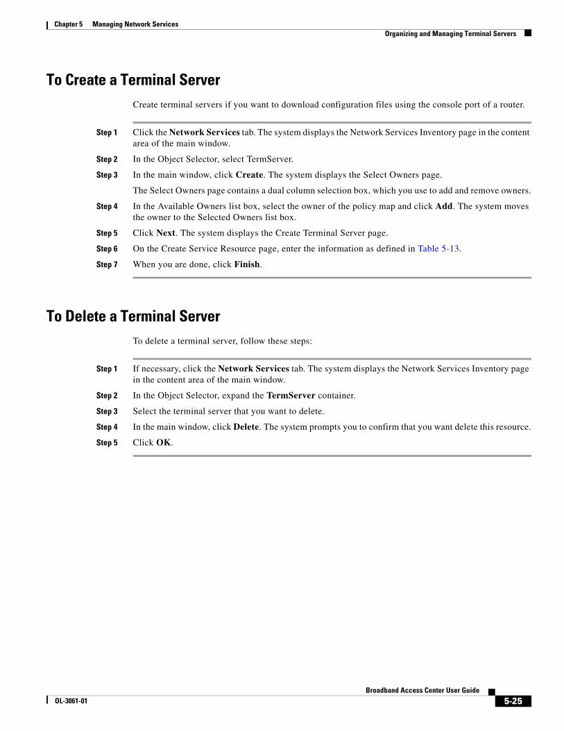
To Create a Terminal ServerCreate terminal servers if you want to download configuration files using the console port of a router.
Step 1 Click the Network Services tab. The system displays the Network Services Inventory page in the content area of the main window.
Step 2 In the Object Selector, select TermServer.
Step 3 In the main window, click Create. The system displays the Select Owners page.
The Select Owners page contains a dual column selection box, which you use to add and remove owners.
Step 4 In the Available Owners list box, select the owner of the policy map and click Add. The system moves the owner to the Selected Owners list box.
Step 5 Click Next. The system displays the Create Terminal Server page.
Step 6 On the Create Service Resource page, enter the information as defined in Table 5-13.
Step 7 When you are done, click Finish.
To Delete a Terminal ServerTo delete a terminal server, follow these steps:
Step 1 If necessary, click the Network Services tab. The system displays the Network Services Inventory page in the content area of the main window.
Step 2 In the Object Selector, expand the TermServer container.
Step 3 Select the terminal server that you want to delete.
Step 4 In the main window, click Delete. The system prompts you to confirm that you want delete this resource.
Step 5 Click OK.
5-25Broadband Access Center User Guide
OL-3061-01

Chapter 5 Managing Network ServicesOrganizing and Managing Tunnels
Organizing and Managing TunnelsYou organize and manage tunnels to encapsulate packets inside a transport protocol. Tunnels provide the ability to implement standard point-to-point encapsulation schemes.
BAC supports two tunneling profiles:
• Cisco tunnel
• IETF tunnel
Note You can customize tunnel Cisco and IETF tunnel characteristics. To customize tunnel open the following files in a text editor:
/opt/CSCObacss/common/templates/Broadband/aggregator-add-cisco-tunnel_TMPL_ /opt/CSCObacss/common/templates/Broadband/aggregator-delete-cisco-tunnel_TMPL_ /opt/CSCObacss/common/templates/Broadband/aggregator-add-ietf-tunnel_TMPL_ /opt/CSCObacss/common/templates/Broadband/aggregator-delete-ietf-tunnel_TMPL_
About Cisco TunnelsWhen you configure a tunnel with Cisco encapsulation, you set the fields listed in Table 5-14.
To Configure Cisco TunnelsTo configure a Cisco tunnel, follow these steps:
Step 1 Click the Network Services tab. The system displays the Network Service Inventory page in the content area of the main window.
Step 2 In the Object Selector, select Tunnel.
Table 5-14 Cisco Tunnel Fields
Field Description
Tunnel Name The name of the L2TP tunnel. A tunnel name is required.
Realm The name of the realm that the AAA server uses to authenticate a user; for example, example.com. A realm is required.
AAA The IP address of the AAA server.
Service Type The type of service: either outbound or inbound.
IP Addresses Destination IP addresses of this tunnel.
Source IP The IP address of the interface from which the encapsulated packets are sent, or specifies the router's IP address.
Tunnel ID The tunnel identifier.
Tunnel Type The tunneling protocol used on this tunnel. Examples include L2TP and the PPP tunneling protocol.
Tunnel Password A password to be used for authentication with a remote server.
5-26Broadband Access Center User Guide
OL-3061-01
Chapter 5 Managing Network ServicesOrganizing and Managing Tunnels
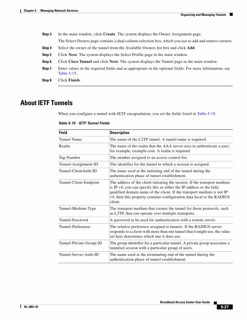
Step 3 In the main window, click Create. The system displays the Owner Assignment page.
The Select Owners page contains a dual column selection box, which you use to add and remove owners.
Step 4 Select the owner of the tunnel from the Available Owners list box and click Add.
Step 5 Click Next. The system displays the Select Profile page in the main window.
Step 6 Click Cisco Tunnel and click Next. The system displays the Tunnel page in the main window.
Step 7 Enter values in the required fields and as appropriate in the optional fields. For more information, see Table 5-15.
Step 8 Click Finish.
About IETF Tunnels When you configure a tunnel with IETF encapsulation, you set the fields listed in Table 5-15.
Table 5-15 IETF Tunnel Fields
Field Description
Tunnel Name The name of the L2TP tunnel. A tunnel name is required.
Realm The name of the realm that the AAA server uses to authenticate a user; for example, example.com. A realm is required.
Tag-Number The number assigned to an access control list.
Tunnel-Assignment-ID The identifier for the tunnel to which a session is assigned.
Tunnel-ClientAuth-ID The name used at the initiating end of the tunnel during the authentication phase of tunnel establishment.
Tunnel-Client-Endpoint The address of the client initiating the session. If the transport medium is IP v4, you can specify this as either the IP address or the fully qualified domain name of the client. If the transport medium is not IP v4, then this property contains configuration data local to the RADIUS client.
Tunnel-Medium-Type The transport medium that creates the tunnel for those protocols, such as L2TP, that can operate over multiple transports.
Tunnel-Password A password to be used for authentication with a remote server.
Tunnel-Preference The relative preference assigned to tunnels. If the RADIUS server responds to a client with more than one tunnel that it might use, the value set here determines which one it does use.
Tunnel-Private-Group-ID The group identifier for a particular tunnel. A private group associates a tunneled session with a particular group of users.
Tunnel-Server-Auth-ID The name used at the terminating end of the tunnel during the authentication phase of tunnel establishment.
5-27Broadband Access Center User Guide
OL-3061-01

Chapter 5 Managing Network ServicesOrganizing and Managing Tunnels
To Configure an IETF TunnelTo configure an IETF tunnel, follow these steps:
Step 1 Click the Network Services tab. The system displays the Network Service Inventory page in the content area of the main window.
Step 2 In the Object Selector, select Tunnel.
Step 3 In the main window, click Create. The system displays the Owner Assignment page.
The Select Owners page contains a dual column selection box, which you use to add and remove owners.
Step 4 Select the owner of the tunnel from the Available Owners list box and click Add.
Step 5 Click Next. The system displays the Select Profile page in the main window.
Step 6 Click IETF Tunnel and click Next. The system displays the Tunnel page in the main window.
Step 7 Enter values in the required fields and as appropriate in the optional fields. For more information, see Table 5-15.
Step 8 Click Finish.
To Delete a TunnelTo delete a tunnel, follow these steps:
Step 1 If necessary, click the Network Services tab. The system displays the Network Services Inventory page in the main window.
Step 2 In the Object Selector, expand the Tunnel container.
Step 3 Select the tunnel that you want to delete.
Step 4 In the main window, click Delete. The system prompts you to confirm that you want delete this resource.
Step 5 Click OK.
Tunnel-Server-Endpoint The address of the server end of the tunnel. If the transport medium is IP v4, you can specify this as either the IP address or the FQDN of the client. If the transport medium is not IP v4, then this property contains local configuration data.
Tunnel-Type The tunneling protocol used on this tunnel. Examples include L2TP and the PPP tunneling protocol.
Table 5-15 IETF Tunnel Fields
Field Description
5-28Broadband Access Center User Guide
OL-3061-01