maintenance of the m249 machinegun -...
TRANSCRIPT

SUBCOURSE EDITIONOD1505 7
MAINTENANCE OF THE M249 MACHINEGUN

US ARMY TANK TURRET REPAIRERCORRESPONDENCE COURSE
MOS/SKILL LEVEL: 45K30
MAINTENANCE OF THE M249 MACHINEGUN
SUBCOURSE NO. OD1505
US Army CorrespondenceCourse Program
6 Credit Hours
GENERAL
The purpose of this subcourse is to increase knowledge of the operation of the M249 machinegun and the maintenance and inspection procedures needed to maintain the machinegun at the operator, unit, and intermediate direct support (IDS) maintenance levels.
Six credit hours are awarded for successful completion of this subcourse. It consists of one lesson of two tasks as follows:
Lesson 1: OPERATION, MAINTENANCE, AND INSPECTION OF THE M249 MACHINEGUN
TASK 1: Describe the operation of the M249 machinegun.
TASK 2: Describe operator, unit, and intermediate direct support (IDS) maintenance, and inspection procedures for the M249 machinegun.
i
M249 MG MAINTENANCE - OD1505
TABLE OF CONTENTS
Section Page
TITLE......................................................... i
TABLE OF CONTENTS ............................................ ii
Lesson 1: OPERATION, MAINTENANCE, ANDINSPECTION OF THE M249 MACHINEGUN................... 1
Task 1: Describe the operation of theM249 machinegun.......................................... 1
Task 2: Describe operator, unit, andintermediate direct support (IDS)maintenance, and inspection procedures forthe M249 machinegun...................................... 16
Practical Exercise 1..................................... 56
Answers to Practical Exercise 1.......................... 58
REFERENCES.................................................... 59
*** IMPORTANT NOTICE ***
THE PASSING SCORE FOR ALL ACCP MATERIAL IS NOW 70%.
PLEASE DISREGARD ALL REFERENCES TO THE 75% REQUIREMENT.
ii

M249 MG MAINTENANCE - OD1505
THIS PAGE INTENTIONALLY LEFT BLANK
iii

M249 MG MAINTENANCE - OD1505
STUDENT NOTES
iv
M249 MG MAINTENANCE - OD1505 - LESSON 1/TASK 1
LESSON 1
OPERATION, MAINTENANCE, AND INSPECTIONOF THE M249 MACHINEGUN
TASK 1. Describe the operation of the M249 machinegun.
CONDITIONS
Within a self-study environment and given the subcourse text, without assistance.
STANDARDS
Within two hours
REFERENCES
No supplementary references are needed for this task.
1. Introduction
The M249 machinegun is designed as a fire team automatic weapon to be used for rear area security and special missions. The machinegun is gas operated, air-cooled, and fires from the open bolt position. It has a regulator for selecting normal or maximum (max) rate of fire. Use of the max rate is authorized only in the event that the weapon's firing rate slows down, otherwise stated: the weapon becomes sluggish. It also has an alternative 30 round magazine feeding provision. The use of the 30 round magazine is authorized only in an emergency situation since the use of the magazine reduces the performance of the machinegun.
This task will describe the major components and equipment data of the M249 machinegun and the operation of the M249 machinegun under usual and unusual conditions.
2. Major Components and Equipment Data of the M249 Machinegun
1
M249 MG MAINTENANCE - OD1505 - LESSON 1/TASK 1
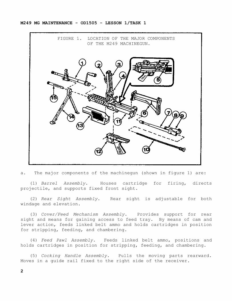
FIGURE 1. LOCATION OF THE MAJOR COMPONENTSOF THE M249 MACHINEGUN.
a. The major components of the machinegun (shown in figure 1) are:
(1) Barrel Assembly. Houses cartridge for firing, directs projectile, and supports fixed front sight.
(2) Rear Sight Assembly. Rear sight is adjustable for both windage and elevation.
(3) Cover/Feed Mechanism Assembly. Provides support for rear sight and means for gaining access to feed tray. By means of cam and lever action, feeds linked belt ammo and holds cartridges in position for stripping, feeding, and chambering.
(4) Feed Pawl Assembly. Feeds linked belt ammo, positions and holds cartridges in position for stripping, feeding, and chambering.
(5) Cocking Handle Assembly. Pulls the moving parts rearward. Moves in a guide rail fixed to the right side of the receiver.
2

M249 MG MAINTENANCE - OD1505 - LESSON 1/TASK 1
(6) Butt Stock and Shoulder Assembly. Serves as a shoulder support for aiming and firing the machinegun. Contains a folding shoulder rest.
(7) Piston Assembly. Transfers power from propelling gases to bolt and slide assemblies as well as to move the recoiling parts rearward.
(8) Bolt Assembly. Provides feeding, stripping, chambering, firing, and extraction, using the propellant gases and recoil spring for power.
(9) Slide Assembly. Houses firing pin and roller assembly.
(10) Rod Buffer and Spring Assembly. Absorbs recoil from bolt and operating rod assembly at the end of recoil movement.
(11) Receiver Assembly. Serves as a support for all major components. Houses action of weapon and, through a series of cam ways, controls functioning of weapon.
(12) Trigger Mechanism Assembly. Controls the firing of the machinegun.
(13) Guard Assembly. Provides thermal insulation to protect the operator's hands from heat, and houses cleaning equipment.
(14) Bipod Machinegun. Supports machinegun in prone and sitting position. The telescopic legs can be individually adjusted to three different lengths.
(15) Gas Cylinder Assembly. Locks bipod in place on receiver and provides passage-way for operating gases.
b. Equipment Data. The equipment data is listed in Table 1 on the following page.
3
M249 MG MAINTENANCE - OD1505 - LESSON 1/TASK 1
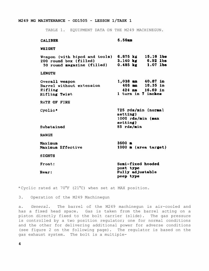
TABLE 1. EQUIPMENT DATA ON THE M249 MACHINEGUN.
*Cyclic rated at 70°F (21°C) when set at MAX position.
3. Operation of the M249 Machinegun
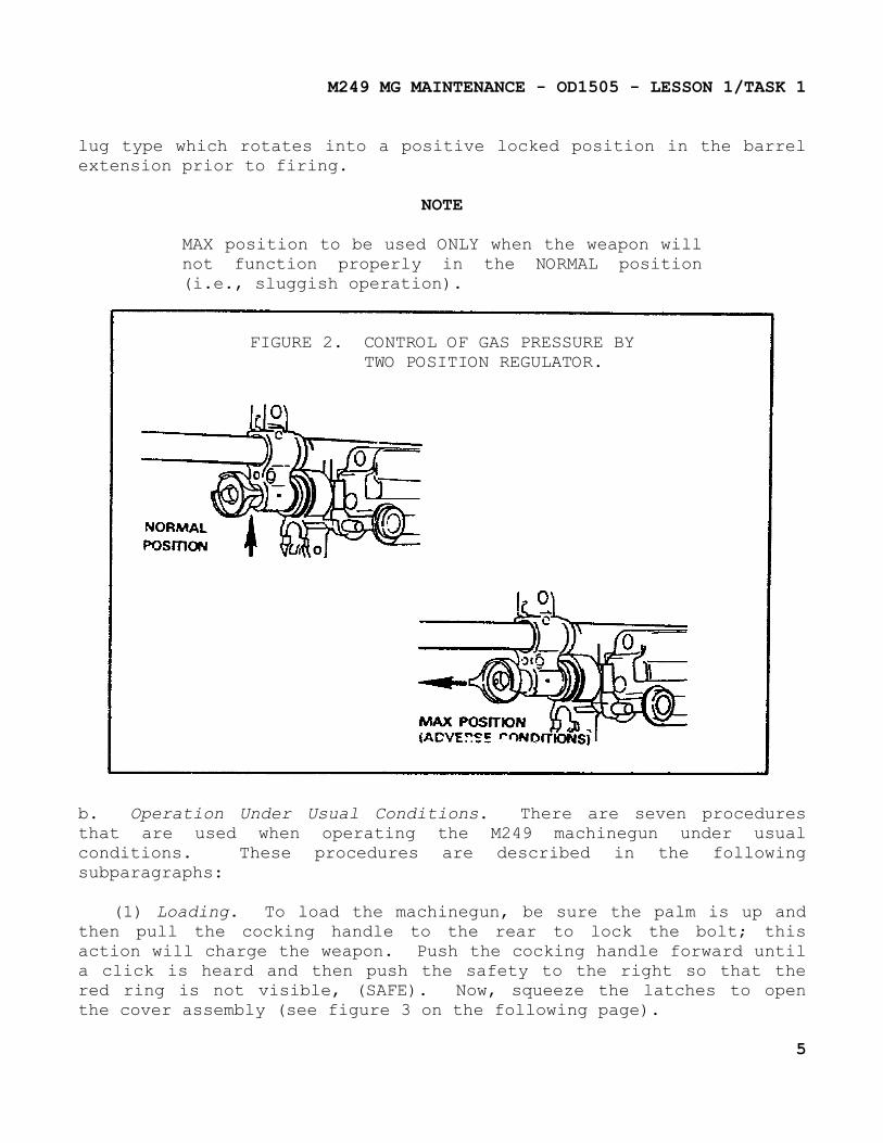
a. General. The barrel of the M249 machinegun is air-cooled and has a fixed head space. Gas is taken from the barrel acting on a piston directly fixed to the bolt carrier (slide). The gas pressure is controlled by a two position regulator; one for normal conditions and the other for delivering additional power for adverse conditions (see figure 2 on the following page). The regulator is based on the gas exhaust system. The bolt is a multiple-
4
M249 MG MAINTENANCE - OD1505 - LESSON 1/TASK 1
lug type which rotates into a positive locked position in the barrel extension prior to firing.
NOTE
MAX position to be used ONLY when the weapon will not function properly in the NORMAL position (i.e., sluggish operation).
FIGURE 2. CONTROL OF GAS PRESSURE BYTWO POSITION REGULATOR.
b. Operation Under Usual Conditions. There are seven procedures that are used when operating the M249 machinegun under usual conditions. These procedures are described in the following subparagraphs:
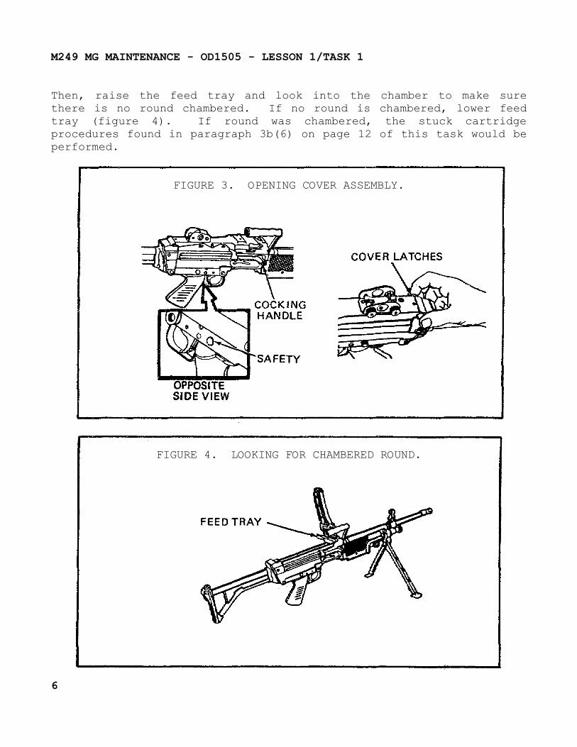
(1) Loading. To load the machinegun, be sure the palm is up and then pull the cocking handle to the rear to lock the bolt; this action will charge the weapon. Push the cocking handle forward until a click is heard and then push the safety to the right so that the red ring is not visible, (SAFE). Now, squeeze the latches to open the cover assembly (see figure 3 on the following page).
5
M249 MG MAINTENANCE - OD1505 - LESSON 1/TASK 1
Then, raise the feed tray and look into the chamber to make sure there is no round chambered. If no round is chambered, lower feed tray (figure 4). If round was chambered, the stuck cartridge procedures found in paragraph 3b(6) on page 12 of this task would be performed.
FIGURE 3. OPENING COVER ASSEMBLY.
FIGURE 4. LOOKING FOR CHAMBERED ROUND.
6
M249 MG MAINTENANCE - OD1505 - LESSON 1/TASK 1
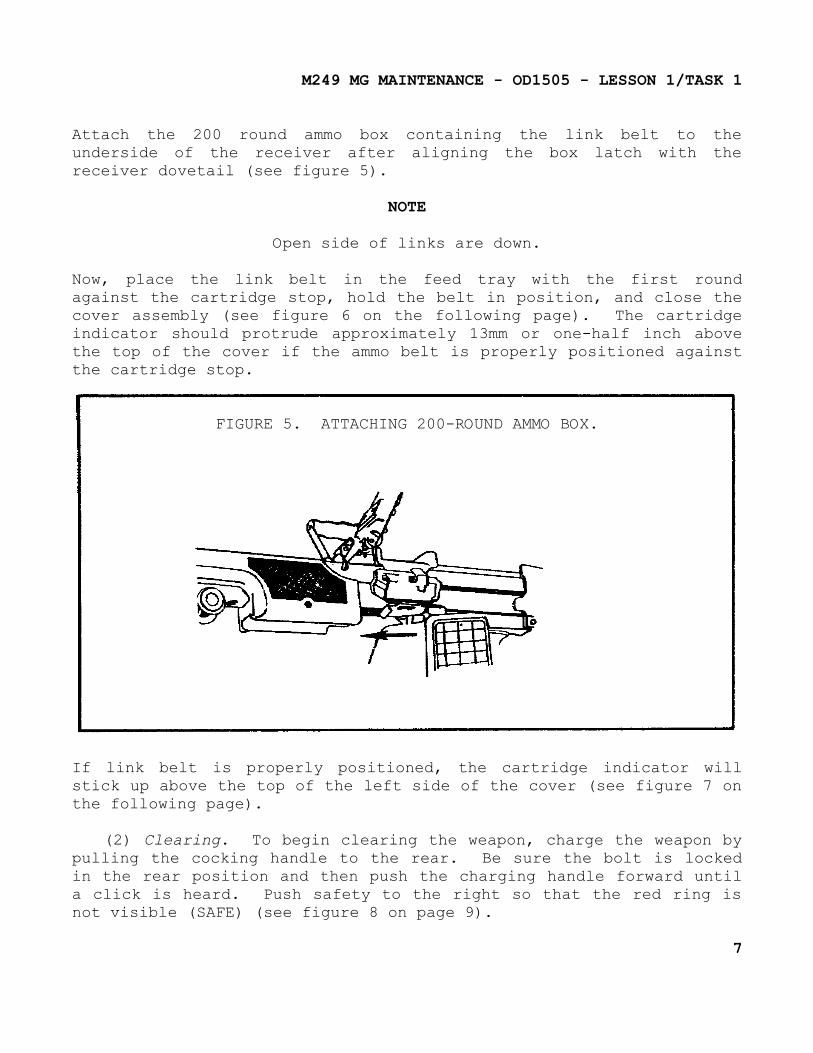
Attach the 200 round ammo box containing the link belt to the underside of the receiver after aligning the box latch with the receiver dovetail (see figure 5).
NOTE
Open side of links are down.
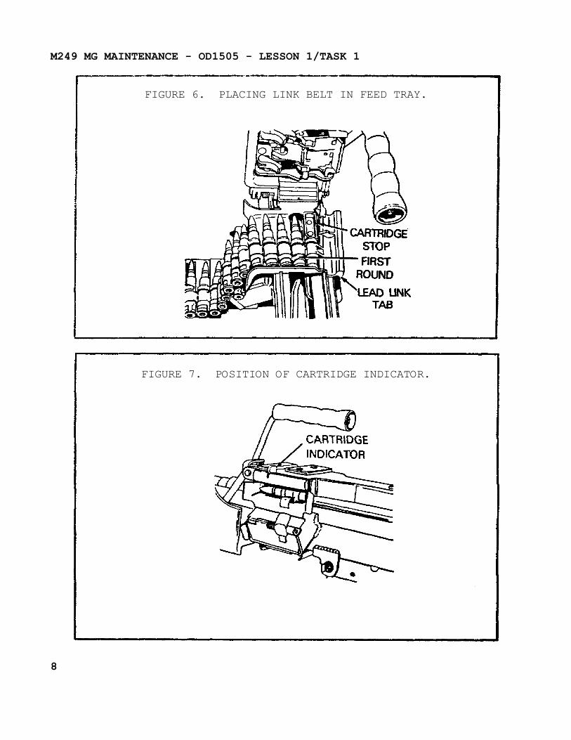
Now, place the link belt in the feed tray with the first round against the cartridge stop, hold the belt in position, and close the cover assembly (see figure 6 on the following page). The cartridge indicator should protrude approximately 13mm or one-half inch above the top of the cover if the ammo belt is properly positioned against the cartridge stop.
FIGURE 5. ATTACHING 200-ROUND AMMO BOX.
If link belt is properly positioned, the cartridge indicator will stick up above the top of the left side of the cover (see figure 7 on the following page).
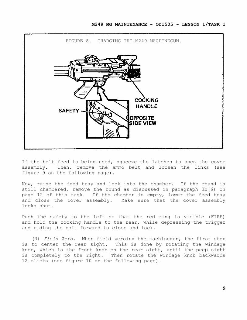
(2) Clearing. To begin clearing the weapon, charge the weapon by pulling the cocking handle to the rear. Be sure the bolt is locked in the rear position and then push the charging handle forward until a click is heard. Push safety to the right so that the red ring is not visible (SAFE) (see figure 8 on page 9).
7
M249 MG MAINTENANCE - OD1505 - LESSON 1/TASK 1
FIGURE 6. PLACING LINK BELT IN FEED TRAY.
FIGURE 7. POSITION OF CARTRIDGE INDICATOR.
8
M249 MG MAINTENANCE - OD1505 - LESSON 1/TASK 1
FIGURE 8. CHARGING THE M249 MACHINEGUN.
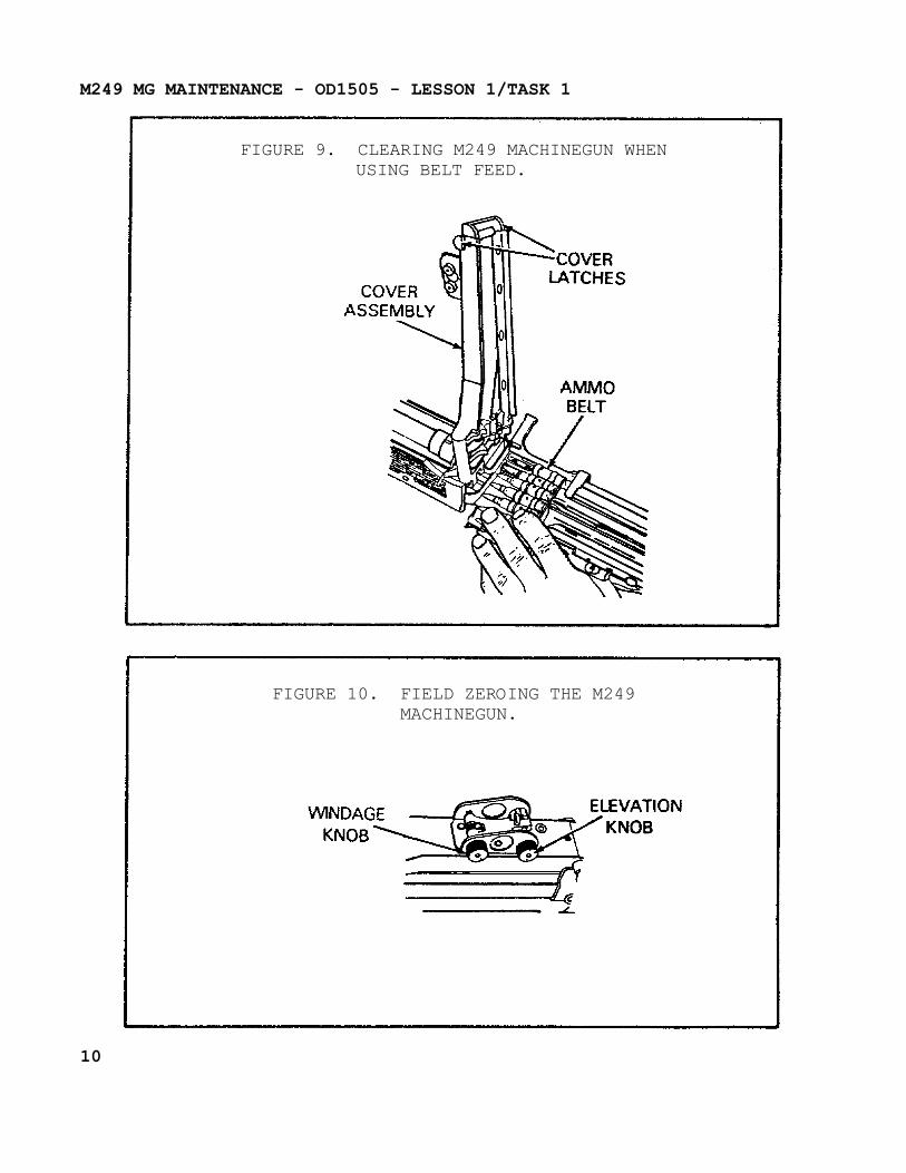
If the belt feed is being used, squeeze the latches to open the cover assembly. Then, remove the ammo belt and loosen the links (see figure 9 on the following page).
Now, raise the feed tray and look into the chamber. If the round is still chambered, remove the round as discussed in paragraph 3b(6) on page 12 of this task. If the chamber is empty, lower the feed tray and close the cover assembly. Make sure that the cover assembly locks shut.
Push the safety to the left so that the red ring is visible (FIRE) and hold the cocking handle to the rear, while depressing the trigger and riding the bolt forward to close and lock.
(3) Field Zero. When field zeroing the machinegun, the first step is to center the rear sight. This is done by rotating the windage knob, which is the front knob on the rear sight, until the peep sight is completely to the right. Then rotate the windage knob backwards 12 clicks (see figure 10 on the following page).
9
M249 MG MAINTENANCE - OD1505 - LESSON 1/TASK 1
FIGURE 9. CLEARING M249 MACHINEGUN WHENUSING BELT FEED.
FIGURE 10. FIELD ZEROING THE M249MACHINEGUN.
10
M249 MG MAINTENANCE - OD1505 - LESSON 1/TASK 1
Each sight may vary as to how many clicks are needed to center the sight. To check the sight, start with the sight all the way to the right, rotate the windage knob backwards until it stops on the left side - count the clicks - divide this number by two - example: 24 clicks = 12 to center; example: 23 clicks = 12 to center (11 + 12 = 23, use larger figure).
Now, rotate the elevation knob to the desired range and fire a 3 to 5 round burst on the center of the target. At this time, fine windage adjustments may be needed. When making the fine windage changes, rotating the windage knob forward will move the impact to the right, and rotating the windage knob backward will move impact to the left.
Each click of the windage knob equals a 1/2 mil which moves the impact a 1/2 meter at a 1000 meters. To change the elevation of the impact, rotate the elevation knob clockwise to lower the impact or rotate the elevation knob counterclockwise to raise the impact.
Each click of the elevation knob equals a 1/2 mil change in elevation. To make the elevation knob easier to grasp, rotate the elevation knob to the 1000 meter (m) mark. After making the fine adjustment, move the elevation knob back to the start position.
(4) Immediate Action. If the weapon stops firing with the trigger depressed, immediate action must be taken. Charge the weapon and push the cocking handle forward until a click is heard. If the round is ejected - FIRE AGAIN!
WARNING
If nothing is ejected and the barrel is hot (200 rounds fired within a 2 minute period), do not open the cover. Push safety to the right so that the red ring is not visible (SAFE). Keep the machinegun pointed downrange, and remain clear for 15 minutes. After 15 minutes, clear the machinegun as described in paragraph 3b(2) on page 7 of this task.
11

M249 MG MAINTENANCE - OD1505 - LESSON 1/TASK 1
If nothing is ejected, and belted ammo is being used, look to see if the cartridge indicator is in the lower (down) position. If it is, and no rounds remain on the feed tray, you have run out of belted ammo. If the cartridge indicator is in the up position and the barrel is not hot, clear the weapon. If nothing is ejected and the alternate magazine feed is being used, and barrel is not hot, clear the weapon.
(5) If Immediate Action Doesn't Work. Be sure the weapon is cleared and then check for dirt, proper lubrication, and obstructions under the feed tray. Reload and fire again.
(6) Stuck Cartridge Case or Live Round.
WARNING
Stay clear of muzzle. Do not allow round to hit any hard surface or it may fire. Dispose of live round in accordance with local regulations.
If round fired but did not extract, the cartridge case is stuck. If round did not fire and did not extract, a live round is stuck. To begin removal of either the cartridge case or live-round, charge the weapon and push the safety to left so that the red ring is visible, (FIRE).
Now, pull the trigger. If the round still doesn't fire, wait until the barrel is cool, which is approximately 15 minutes. Charge the weapon, place the safety on safe and remove the barrel. Removal procedures for the barrel are found in paragraph 20 of task 2 on page 20 of this subcourse.
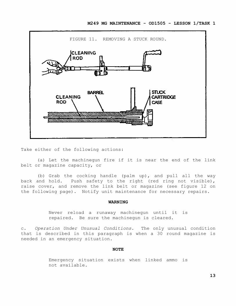
Assemble the cleaning rod without the swab holder and insert the rod through the muzzle end of the barrel. Then gently tap out the case or round (see figure 11 on the following page).
(7) Runaway Machinegun. A runaway machinegun can be described as a machinegun that won't stop firing. If runaway occurs, take action to correct it quickly.
WARNING
Always keep machinegun pointed downrange.
12
M249 MG MAINTENANCE - OD1505 - LESSON 1/TASK 1
FIGURE 11. REMOVING A STUCK ROUND.
Take either of the following actions:
(a) Let the machinegun fire if it is near the end of the link belt or magazine capacity, or
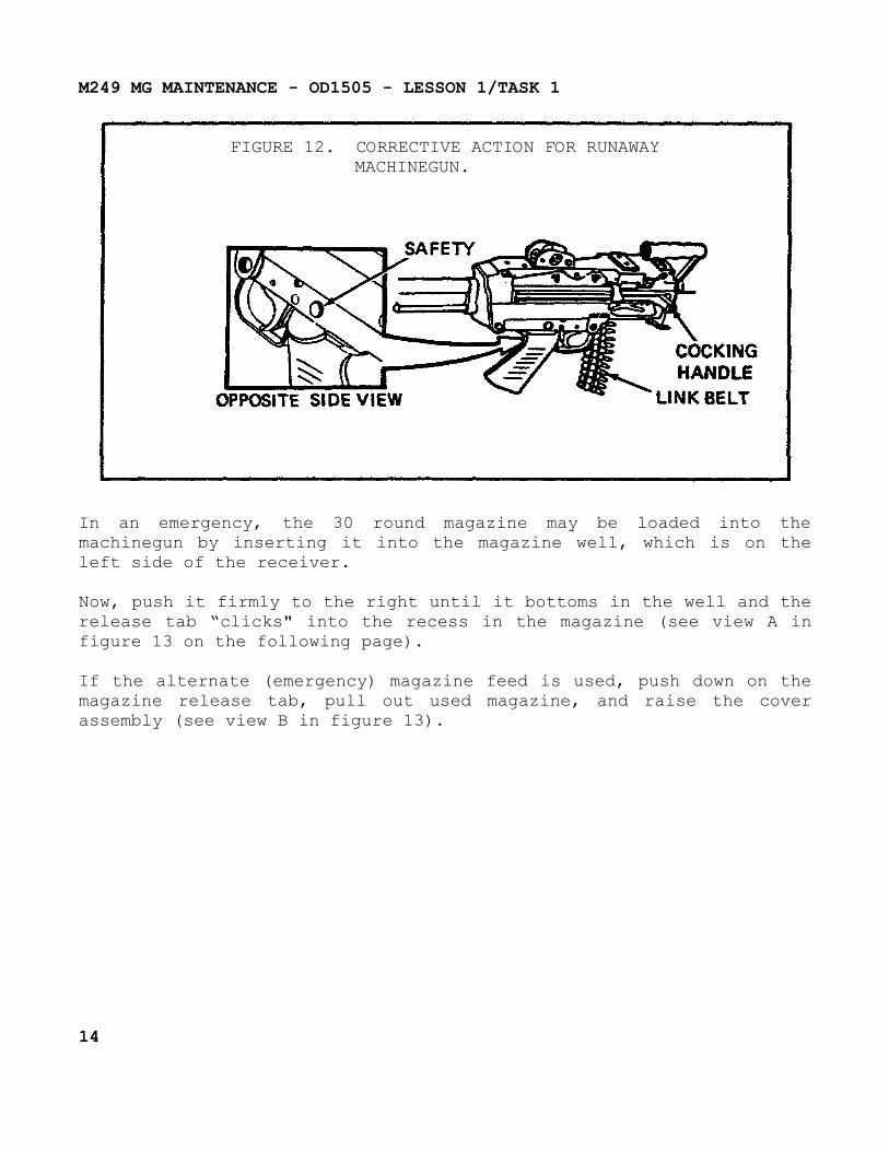
(b) Grab the cocking handle (palm up), and pull all the way back and hold. Push safety to the right (red ring not visible), raise cover, and remove the link belt or magazine (see figure 12 on the following page). Notify unit maintenance for necessary repairs.
WARNING
Never reload a runaway machinegun until it is repaired. Be sure the machinegun is cleared.
c. Operation Under Unusual Conditions. The only unusual condition that is described in this paragraph is when a 30 round magazine is needed in an emergency situation.
NOTE
Emergency situation exists when linked ammo is not available.
13
M249 MG MAINTENANCE - OD1505 - LESSON 1/TASK 1
FIGURE 12. CORRECTIVE ACTION FOR RUNAWAYMACHINEGUN.
In an emergency, the 30 round magazine may be loaded into the machinegun by inserting it into the magazine well, which is on the left side of the receiver.
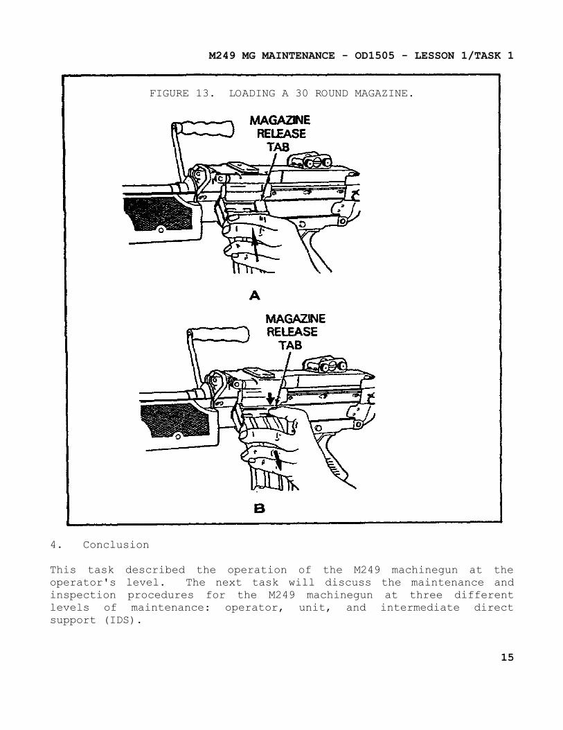
Now, push it firmly to the right until it bottoms in the well and the release tab “clicks" into the recess in the magazine (see view A in figure 13 on the following page).
If the alternate (emergency) magazine feed is used, push down on the magazine release tab, pull out used magazine, and raise the cover assembly (see view B in figure 13).
14
M249 MG MAINTENANCE - OD1505 - LESSON 1/TASK 1
FIGURE 13. LOADING A 30 ROUND MAGAZINE.
4. Conclusion
This task described the operation of the M249 machinegun at the operator's level. The next task will discuss the maintenance and inspection procedures for the M249 machinegun at three different levels of maintenance: operator, unit, and intermediate direct support (IDS).
15
M249 MG MAINTENANCE - OD1505 - LESSON 1/TASK 2
LESSON 1
OPERATION, MAINTENANCE, AND INSPECTIONOF THE M249 MACHINEGUN
TASK 2. Describe operator, unit, and intermediate direct support (IDS) maintenance, and inspection procedures for the M249 machinegun.
CONDITIONS
Within a self-study environment and given the subcourse text, without assistance.
STANDARDS
Within three hours
REFERENCES
No supplementary references are needed for this task.
1. Introduction
The M249 machinegun must operate properly when used for rear area security or when used for special missions. This task will provide examples of maintenance and inspection procedures needed to keep the machinegun operational. These procedures are intended for the operator, unit maintenance, and intermediate direct support (IDS) maintenance.
2. Field Stripping the M249 Machinegun
a. General. To perform maintenance on the M249 machinegun, it must be field stripped to make every component accessible. The following paragraphs will supply the field stripping procedures.
NOTE
Before executing these procedures, the machinegun must be cleared.
16
M249 MG MAINTENANCE - OD1505 - LESSON 1/TASK 2
b. Operating Rod Assembly Removal.
WARNING
Be sure the bolt is in the forward position before removing return spring.
If the moving parts are situated at the rear, put safety on fire and hold the cocking handle with one hand. Press the trigger and let the moving parts come slowly forward.
Raise the cover assembly and pull the upper retaining pin at the rear of receiver to the left.
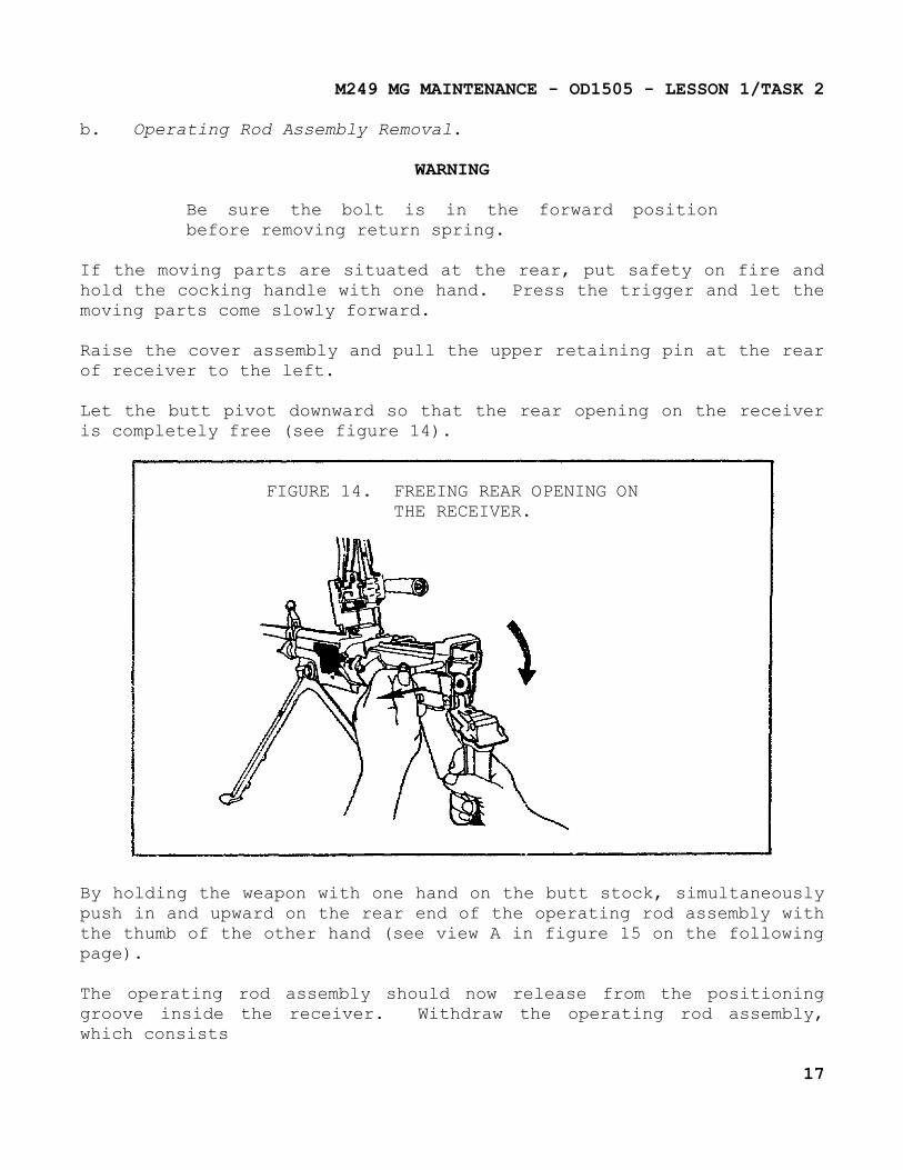
Let the butt pivot downward so that the rear opening on the receiver is completely free (see figure 14).
FIGURE 14. FREEING REAR OPENING ONTHE RECEIVER.
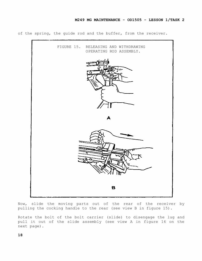
By holding the weapon with one hand on the butt stock, simultaneously push in and upward on the rear end of the operating rod assembly with the thumb of the other hand (see view A in figure 15 on the following page).
The operating rod assembly should now release from the positioning groove inside the receiver. Withdraw the operating rod assembly, which consists
17
M249 MG MAINTENANCE - OD1505 - LESSON 1/TASK 2
of the spring, the guide rod and the buffer, from the receiver.
FIGURE 15. RELEASING AND WITHDRAWINGOPERATING ROD ASSEMBLY.
Now, slide the moving parts out of the rear of the receiver by pulling the cocking handle to the rear (see view B in figure 15).
Rotate the bolt of the bolt carrier (slide) to disengage the lug and pull it out of the slide assembly (see view A in figure 16 on the next page).
18
M249 MG MAINTENANCE - OD1505 - LESSON 1/TASK 2
CAUTION
When the bolt is removed, the firing pin spring is free. Be careful not to lose it.
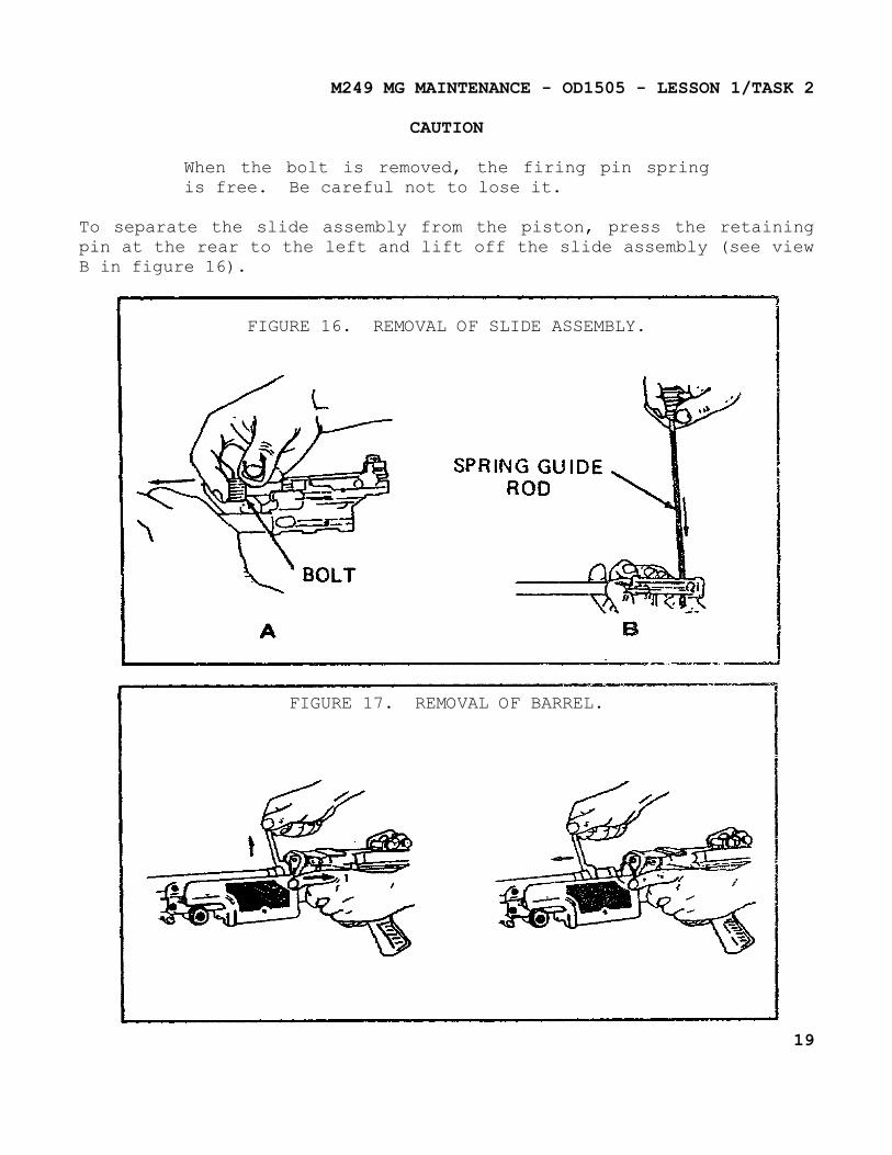
To separate the slide assembly from the piston, press the retaining pin at the rear to the left and lift off the slide assembly (see view B in figure 16).
FIGURE 16. REMOVAL OF SLIDE ASSEMBLY.
FIGURE 17. REMOVAL OF BARREL.
19
M249 MG MAINTENANCE - OD1505 - LESSON 1/TASK 2
c. Barrel Removal. Close the cover and depress the locking lever of the barrel with the left hand. Hold the carrying handle with the right hand, lift it up and push the barrel forward (see figure 17 on the previous page).
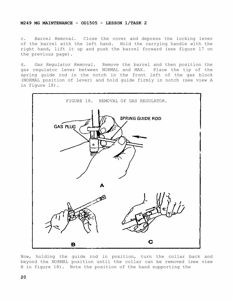
d. Gas Regulator Removal. Remove the barrel and then position the gas regulator lever between NORMAL and MAX. Place the tip of the spring guide rod in the notch in the front left of the gas block (NORMAL position of lever) and hold guide firmly in notch (see view A in figure 18).
FIGURE 18. REMOVAL OF GAS REGULATOR.
Now, holding the guide rod in position, turn the collar back and beyond the NORMAL position until the collar can be removed (see view B in figure 18). Note the position of the hand supporting the
20
M249 MG MAINTENANCE - OD1505 - LESSON 1/TASK 2
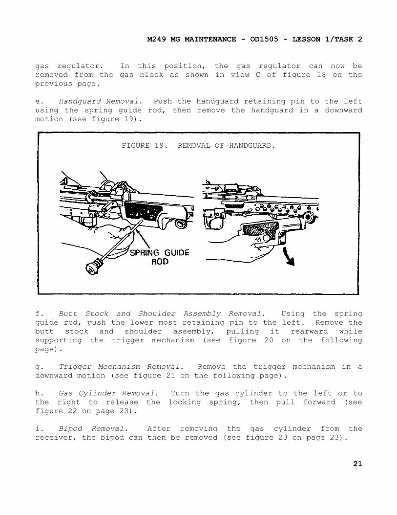
gas regulator. In this position, the gas regulator can now be removed from the gas block as shown in view C of figure 18 on the previous page.
e. Handguard Removal. Push the handguard retaining pin to the left using the spring guide rod, then remove the handguard in a downward motion (see figure 19).
FIGURE 19. REMOVAL OF HANDGUARD.
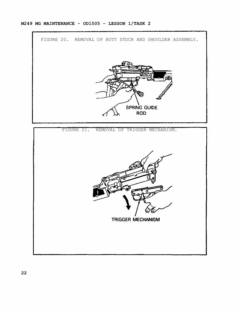
f. Butt Stock and Shoulder Assembly Removal. Using the spring guide rod, push the lower most retaining pin to the left. Remove the butt stock and shoulder assembly, pulling it rearward while supporting the trigger mechanism (see figure 20 on the following page).
g. Trigger Mechanism Removal. Remove the trigger mechanism in a downward motion (see figure 21 on the following page).
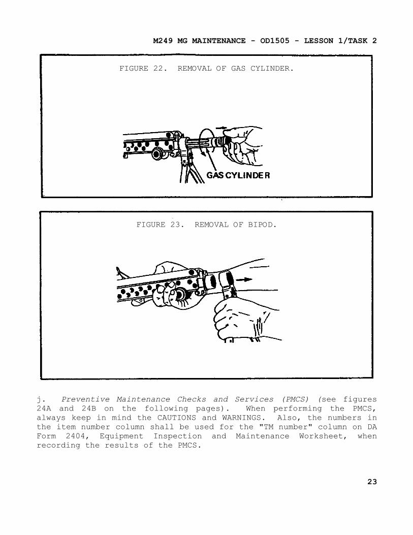
h. Gas Cylinder Removal. Turn the gas cylinder to the left or to the right to release the locking spring, then pull forward (see figure 22 on page 23).
i. Bipod Removal. After removing the gas cylinder from the receiver, the bipod can then be removed (see figure 23 on page 23).
21
M249 MG MAINTENANCE - OD1505 - LESSON 1/TASK 2
FIGURE 20. REMOVAL OF BUTT STOCK AND SHOULDER ASSEMBLY.
FIGURE 21. REMOVAL OF TRIGGER MECHANISM.
22
M249 MG MAINTENANCE - OD1505 - LESSON 1/TASK 2
FIGURE 22. REMOVAL OF GAS CYLINDER.
FIGURE 23. REMOVAL OF BIPOD.
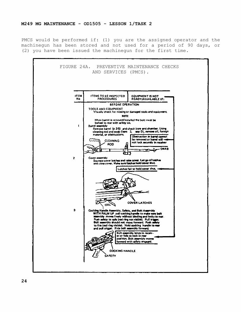
j. Preventive Maintenance Checks and Services (PMCS) (see figures 24A and 24B on the following pages). When performing the PMCS, always keep in mind the CAUTIONS and WARNINGS. Also, the numbers in the item number column shall be used for the "TM number" column on DA Form 2404, Equipment Inspection and Maintenance Worksheet, when recording the results of the PMCS.
23
M249 MG MAINTENANCE - OD1505 - LESSON 1/TASK 2
PMCS would be performed if: (1) you are the assigned operator and the machinegun has been stored and not used for a period of 90 days, or (2) you have been issued the machinegun for the first time.
FIGURE 24A. PREVENTIVE MAINTENANCE CHECKS AND SERVICES (PMCS).
24
M249 MG MAINTENANCE - OD1505 - LESSON 1/TASK 2
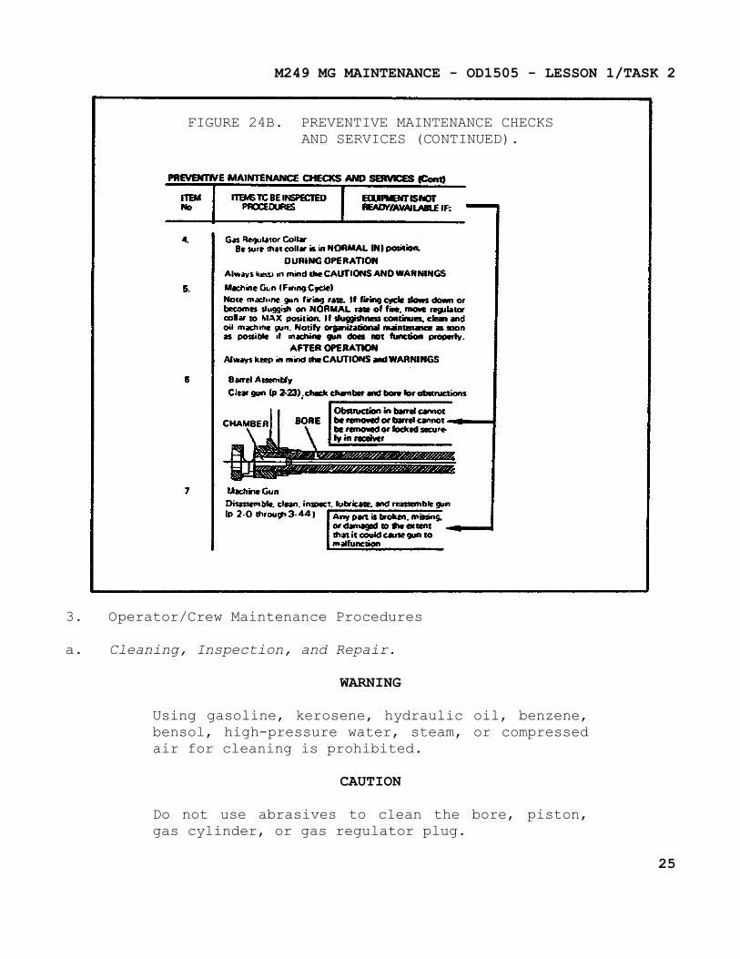
FIGURE 24B. PREVENTIVE MAINTENANCE CHECKSAND SERVICES (CONTINUED).
3. Operator/Crew Maintenance Procedures
a. Cleaning, Inspection, and Repair.
WARNING
Using gasoline, kerosene, hydraulic oil, benzene, bensol, high-pressure water, steam, or compressed air for cleaning is prohibited.
CAUTION
Do not use abrasives to clean the bore, piston, gas cylinder, or gas regulator plug.
25
M249 MG MAINTENANCE - OD1505 - LESSON 1/TASK 2
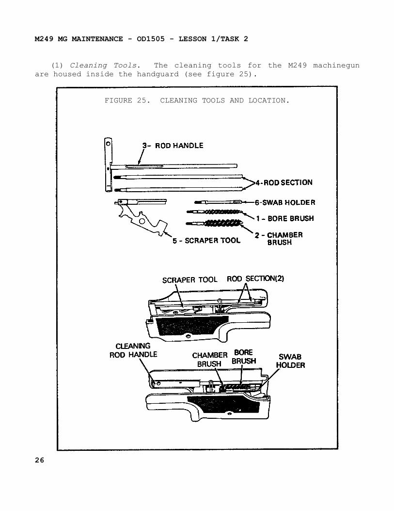
(1) Cleaning Tools. The cleaning tools for the M249 machinegun are housed inside the handguard (see figure 25).
FIGURE 25. CLEANING TOOLS AND LOCATION.
26
M249 MG MAINTENANCE - OD1505 - LESSON 1/TASK 2
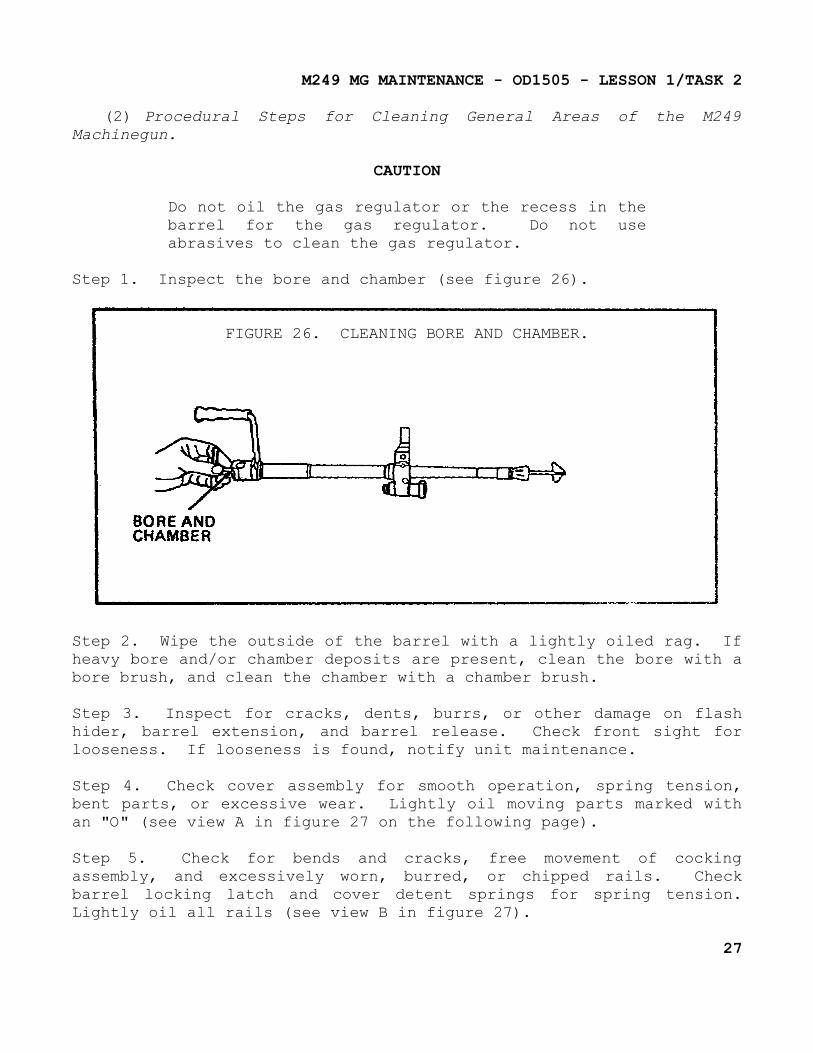
(2) Procedural Steps for Cleaning General Areas of the M249 Machinegun.
CAUTION
Do not oil the gas regulator or the recess in the barrel for the gas regulator. Do not use abrasives to clean the gas regulator.
Step 1. Inspect the bore and chamber (see figure 26).
FIGURE 26. CLEANING BORE AND CHAMBER.
Step 2. Wipe the outside of the barrel with a lightly oiled rag. If heavy bore and/or chamber deposits are present, clean the bore with a bore brush, and clean the chamber with a chamber brush.
Step 3. Inspect for cracks, dents, burrs, or other damage on flash hider, barrel extension, and barrel release. Check front sight for looseness. If looseness is found, notify unit maintenance.
Step 4. Check cover assembly for smooth operation, spring tension, bent parts, or excessive wear. Lightly oil moving parts marked with an "O" (see view A in figure 27 on the following page).
Step 5. Check for bends and cracks, free movement of cocking assembly, and excessively worn, burred, or chipped rails. Check barrel locking latch and cover detent springs for spring tension. Lightly oil all rails (see view B in figure 27).
27
M249 MG MAINTENANCE - OD1505 - LESSON 1/TASK 2
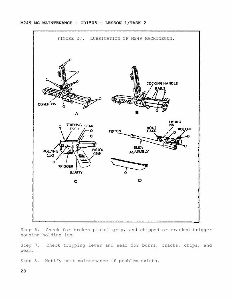
FIGURE 27. LUBRICATION OF M249 MACHINEGUN.
Step 6. Check for broken pistol grip, and chipped or cracked trigger housing holding lug.
Step 7. Check tripping lever and sear for burrs, cracks, chips, and wear.
Step 8. Notify unit maintenance if problem exists.
28
M249 MG MAINTENANCE - OD1505 - LESSON 1/TASK 2
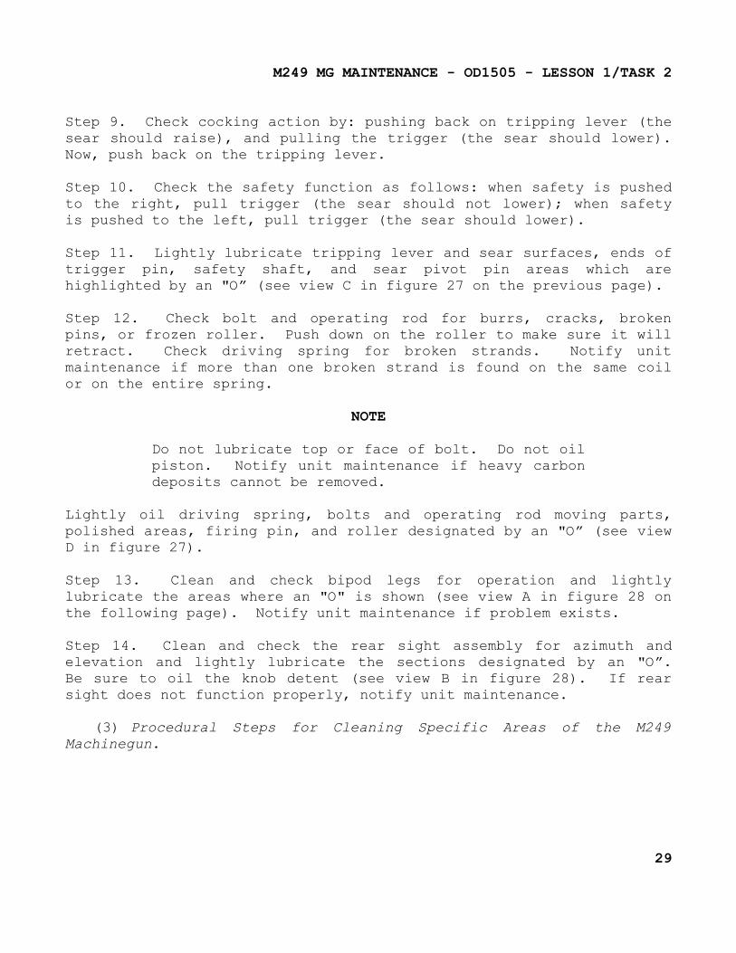
Step 9. Check cocking action by: pushing back on tripping lever (the sear should raise), and pulling the trigger (the sear should lower). Now, push back on the tripping lever.
Step 10. Check the safety function as follows: when safety is pushed to the right, pull trigger (the sear should not lower); when safety is pushed to the left, pull trigger (the sear should lower).
Step 11. Lightly lubricate tripping lever and sear surfaces, ends of trigger pin, safety shaft, and sear pivot pin areas which are highlighted by an "O” (see view C in figure 27 on the previous page).
Step 12. Check bolt and operating rod for burrs, cracks, broken pins, or frozen roller. Push down on the roller to make sure it will retract. Check driving spring for broken strands. Notify unit maintenance if more than one broken strand is found on the same coil or on the entire spring.
NOTE
Do not lubricate top or face of bolt. Do not oil piston. Notify unit maintenance if heavy carbon deposits cannot be removed.
Lightly oil driving spring, bolts and operating rod moving parts, polished areas, firing pin, and roller designated by an "O” (see view D in figure 27).
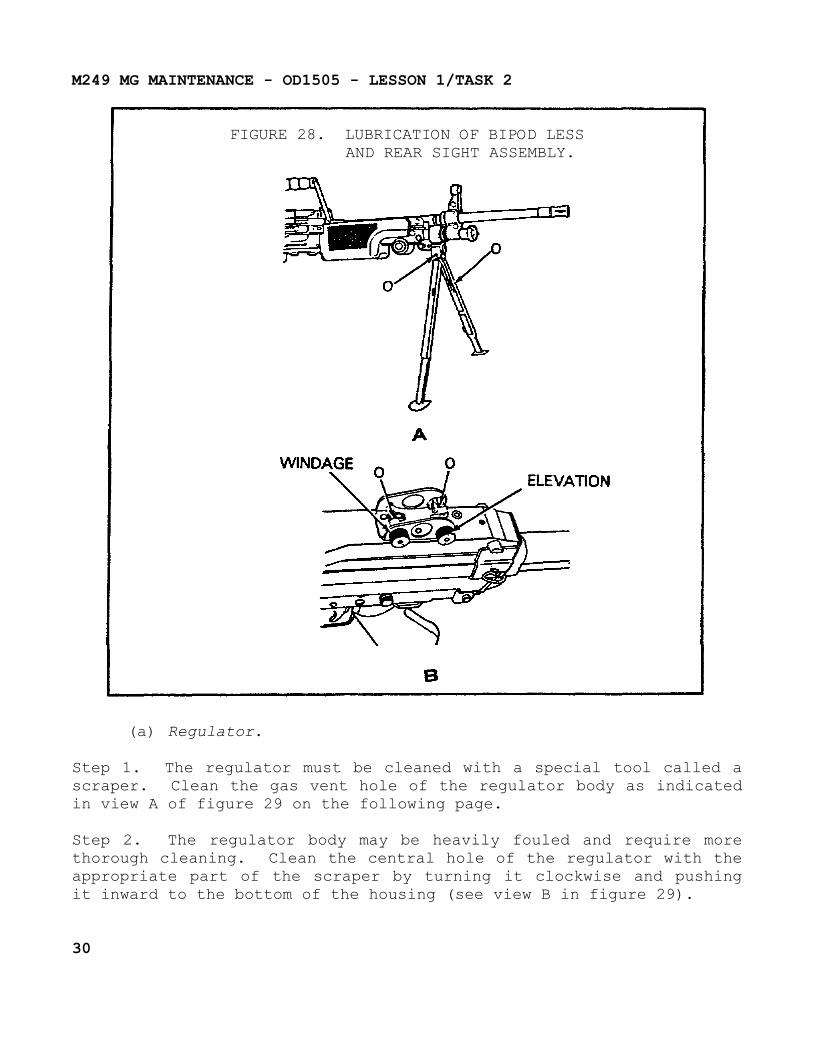
Step 13. Clean and check bipod legs for operation and lightly lubricate the areas where an "O" is shown (see view A in figure 28 on the following page). Notify unit maintenance if problem exists.
Step 14. Clean and check the rear sight assembly for azimuth and elevation and lightly lubricate the sections designated by an "O”. Be sure to oil the knob detent (see view B in figure 28). If rear sight does not function properly, notify unit maintenance.
(3) Procedural Steps for Cleaning Specific Areas of the M249 Machinegun.
29
M249 MG MAINTENANCE - OD1505 - LESSON 1/TASK 2
FIGURE 28. LUBRICATION OF BIPOD LESSAND REAR SIGHT ASSEMBLY.
(a) Regulator.
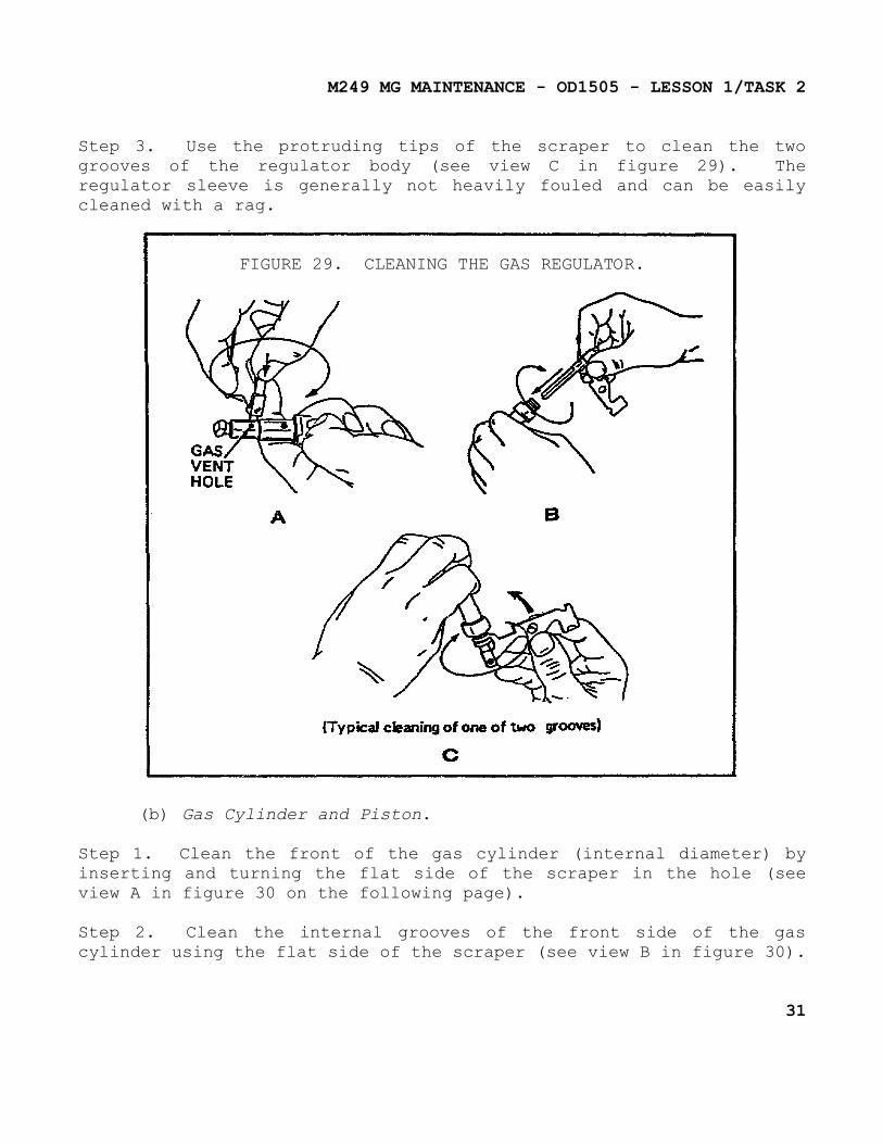
Step 1. The regulator must be cleaned with a special tool called a scraper. Clean the gas vent hole of the regulator body as indicated in view A of figure 29 on the following page.
Step 2. The regulator body may be heavily fouled and require more thorough cleaning. Clean the central hole of the regulator with the appropriate part of the scraper by turning it clockwise and pushing it inward to the bottom of the housing (see view B in figure 29).
30
M249 MG MAINTENANCE - OD1505 - LESSON 1/TASK 2
Step 3. Use the protruding tips of the scraper to clean the two grooves of the regulator body (see view C in figure 29). The regulator sleeve is generally not heavily fouled and can be easily cleaned with a rag.
FIGURE 29. CLEANING THE GAS REGULATOR.
(b) Gas Cylinder and Piston.
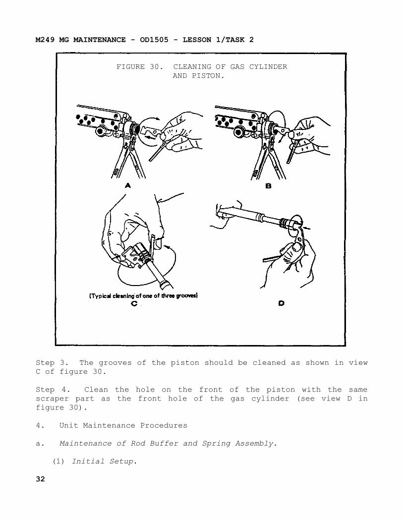
Step 1. Clean the front of the gas cylinder (internal diameter) by inserting and turning the flat side of the scraper in the hole (see view A in figure 30 on the following page).
Step 2. Clean the internal grooves of the front side of the gas cylinder using the flat side of the scraper (see view B in figure 30).
31
M249 MG MAINTENANCE - OD1505 - LESSON 1/TASK 2
FIGURE 30. CLEANING OF GAS CYLINDERAND PISTON.
Step 3. The grooves of the piston should be cleaned as shown in view C of figure 30.
Step 4. Clean the hole on the front of the piston with the same scraper part as the front hole of the gas cylinder (see view D in figure 30).
4. Unit Maintenance Procedures
a. Maintenance of Rod Buffer and Spring Assembly.
(1) Initial Setup.
32
M249 MG MAINTENANCE - OD1505 - LESSON 1/TASK 2
(a) Materials/Parts. Cleaner lubricant preservative (CLP); small arms repairman tool kit.
(b) Personnel Required. Supply clerk/unit armor.
(c) Equipment Condition. Rod buffer and spring assembly removed.
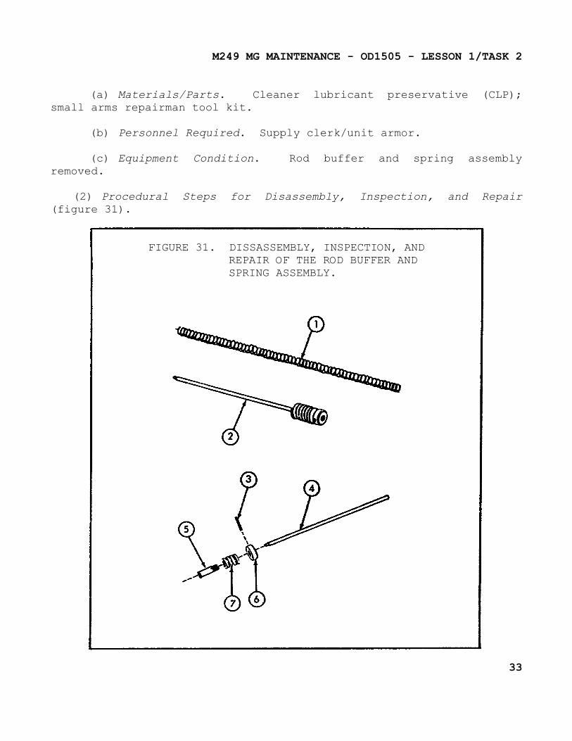
(2) Procedural Steps for Disassembly, Inspection, and Repair (figure 31).
FIGURE 31. DISSASSEMBLY, INSPECTION, ANDREPAIR OF THE ROD BUFFER ANDSPRING ASSEMBLY.
33
M249 MG MAINTENANCE - OD1505 - LESSON 1/TASK 2
Step 1. Replace driving spring (1) if more than one broken strand is found or overall spring length is less than 18 and 9/16 inches long.
Step 2. Place the rod buffer assembly (2) in vise with protective jaws in a vertical position.
Step 3. Use punch and hammer to drive out pin (3), and remove rod (4).
Step 4. Unscrew and separate spring pin (5), ring spacer (6), and buffer spring (7).
Step 5. Visually inspect rod (4). If bent, or tip of rod (4) is missing, replace.
Step 6. Check spring (7) for cracks. If spring is cracked, replace.
Step 7. Check spacer (6) for burrs. Remove any burrs that are found.
Step 8. Check spring pin (5) for missing threads or cracks. Replace spring if damaged.
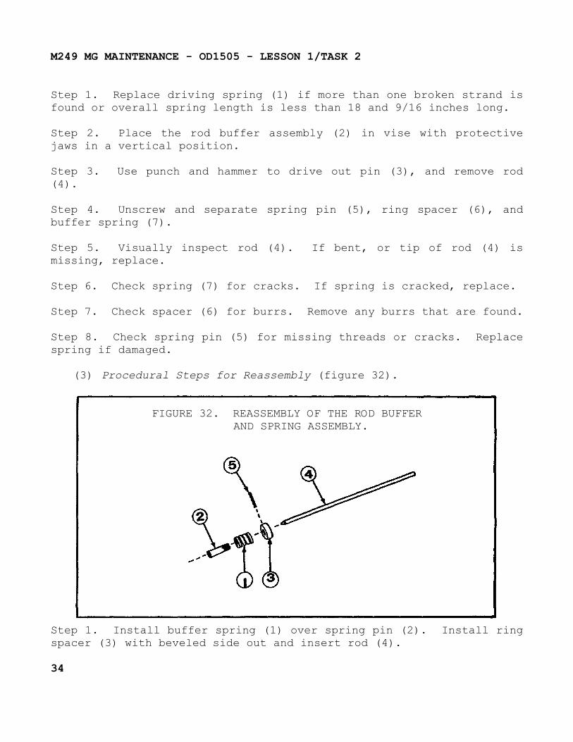
(3) Procedural Steps for Reassembly (figure 32).
FIGURE 32. REASSEMBLY OF THE ROD BUFFERAND SPRING ASSEMBLY.
Step 1. Install buffer spring (1) over spring pin (2). Install ring spacer (3) with beveled side out and insert rod (4).
34
M249 MG MAINTENANCE - OD1505 - LESSON 1/TASK 2
Step 2. Screw spring pin (2) until it is flush with or just below the pin hole in spacer (3).
Step 3. Align the slot in spring pin (2) with holes in spacer (3).
Step 4. Use a hammer to drive pin (5) until equal lengths are exposed on each side of the ring spacer.
b. Maintenance of Trigger Mechanism Assembly.
(1) Initial Setup.
(a) Tools and Special Tools. Small arms repairman tool kit; box spanner.
(b) Materials/Parts. Cleaner lubricant preservative (CLP).
(c) Personnel Required. Supply clerk/unit armorer.
(d) Equipment Condition. Trigger mechanism removed.
(2) Procedural Steps for Disassembly, Cleaning, Inspection, and Repair.
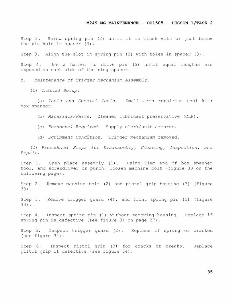
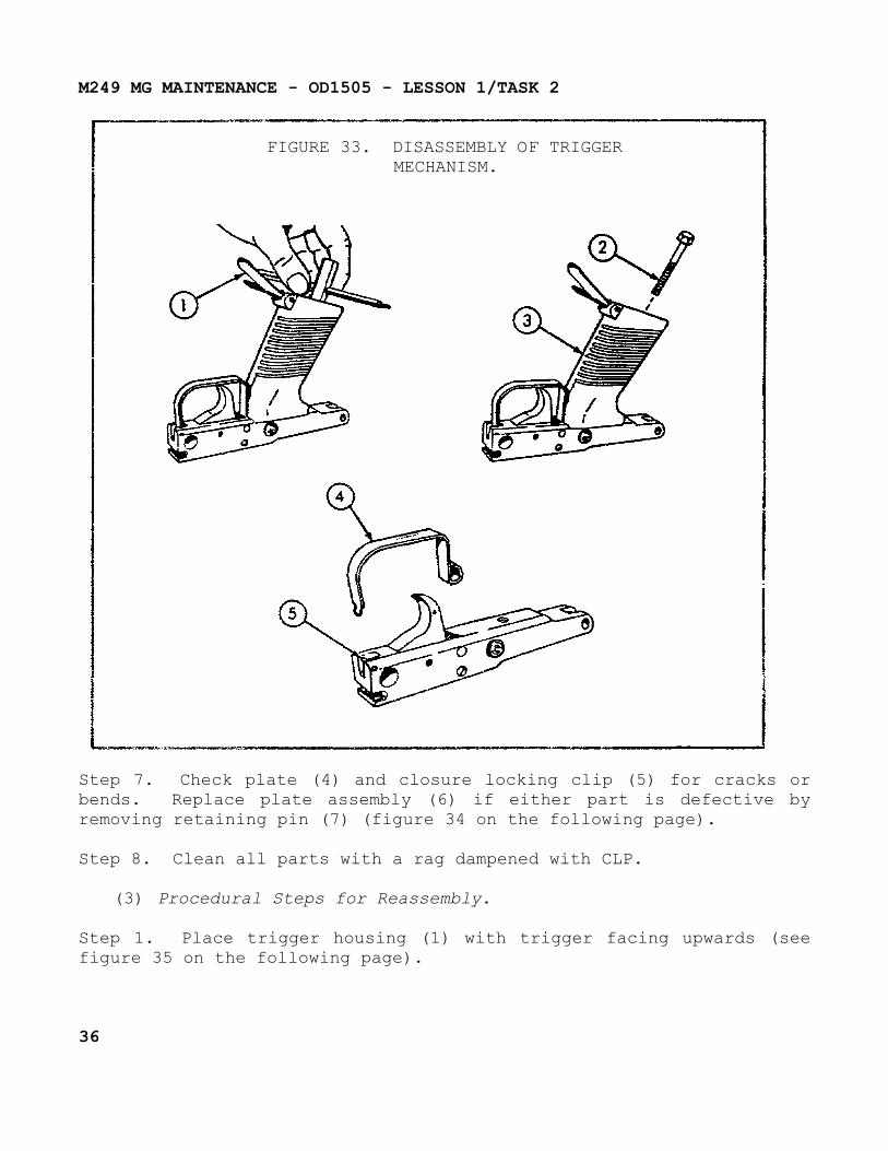
Step 1. Open plate assembly (1). Using 11mm end of box spanner tool, and screwdriver or punch, loosen machine bolt (figure 33 on the following page).
Step 2. Remove machine bolt (2) and pistol grip housing (3) (figure 33).
Step 3. Remove trigger guard (4), and front spring pin (5) (figure 33).
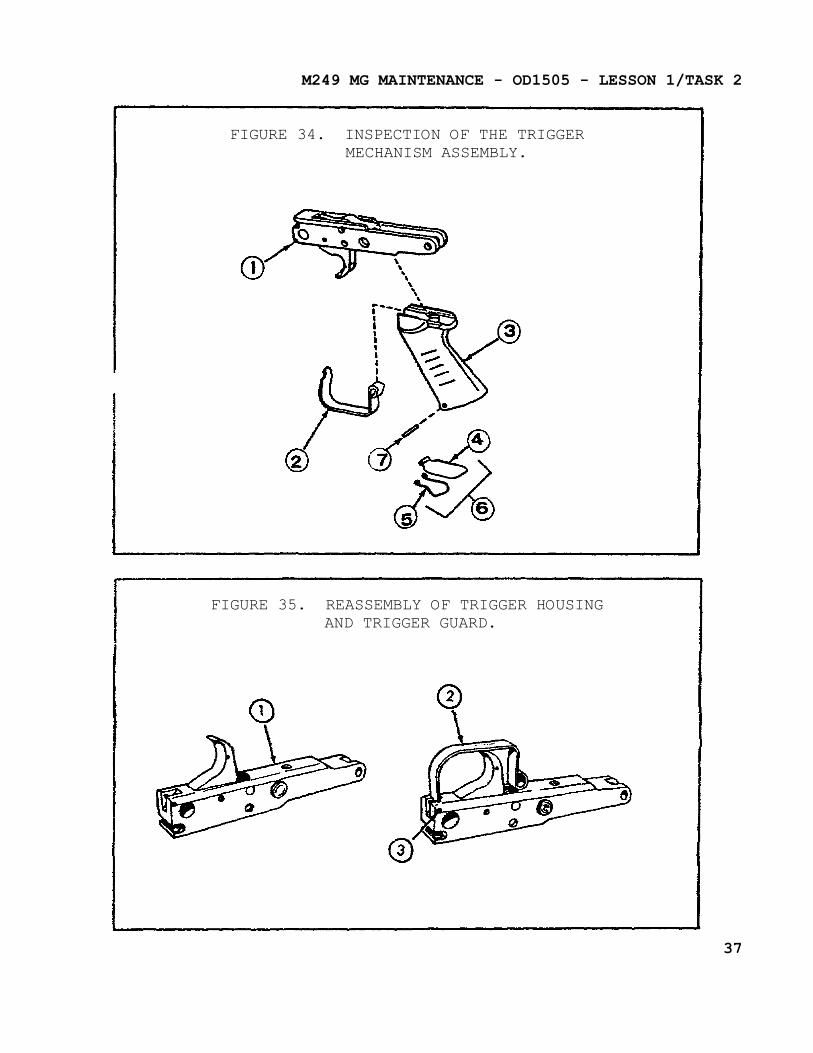
Step 4. Inspect spring pin (1) without removing housing. Replace if spring pin is defective (see figure 34 on page 37).
Step 5. Inspect trigger guard (2). Replace if sprung or cracked (see figure 34).
Step 6. Inspect pistol grip (3) for cracks or breaks. Replace pistol grip if defective (see figure 34).
35
M249 MG MAINTENANCE - OD1505 - LESSON 1/TASK 2
FIGURE 33. DISASSEMBLY OF TRIGGERMECHANISM.
Step 7. Check plate (4) and closure locking clip (5) for cracks or bends. Replace plate assembly (6) if either part is defective by removing retaining pin (7) (figure 34 on the following page).
Step 8. Clean all parts with a rag dampened with CLP.
(3) Procedural Steps for Reassembly.
Step 1. Place trigger housing (1) with trigger facing upwards (see figure 35 on the following page).
36
M249 MG MAINTENANCE - OD1505 - LESSON 1/TASK 2
FIGURE 34. INSPECTION OF THE TRIGGERMECHANISM ASSEMBLY.
FIGURE 35. REASSEMBLY OF TRIGGER HOUSINGAND TRIGGER GUARD.
37
M249 MG MAINTENANCE - OD1505 - LESSON 1/TASK 2
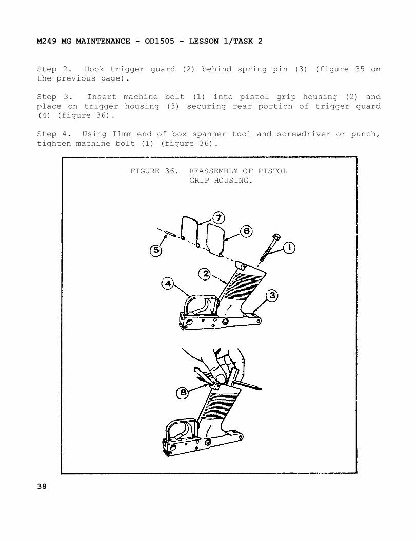
Step 2. Hook trigger guard (2) behind spring pin (3) (figure 35 on the previous page).
Step 3. Insert machine bolt (1) into pistol grip housing (2) and place on trigger housing (3) securing rear portion of trigger guard (4) (figure 36).
Step 4. Using I1mm end of box spanner tool and screwdriver or punch, tighten machine bolt (1) (figure 36).
FIGURE 36. REASSEMBLY OF PISTOLGRIP HOUSING.
38
M249 MG MAINTENANCE - OD1505 - LESSON 1/TASK 2
Step 5. Install retaining pin (5) securing plate (6) and locking clip (7) in pistol grip housing (2) (figure 36 on the previous page).
Step 6. Close plate assembly (8) (figure 36).
c. Maintenance of Receiver Assembly.
(1) Initial Setup.
(a) Tools and Special Tools. Small arms repairman tool kit.
(b) Personnel Required. Supply clerk/unit armor.
(c) Equipment Condition. Field stripped.
(2) Procedural Steps for Disassembly, Inspection, and Repair.
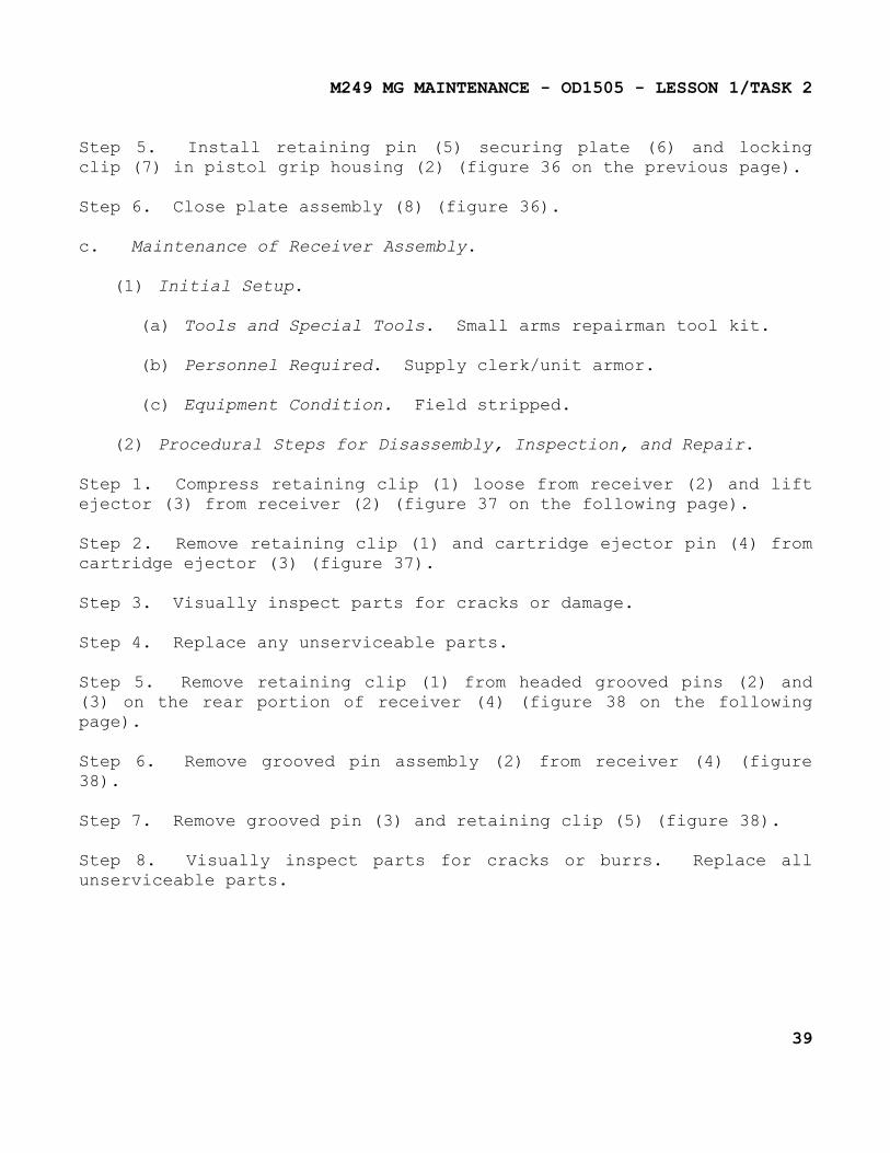
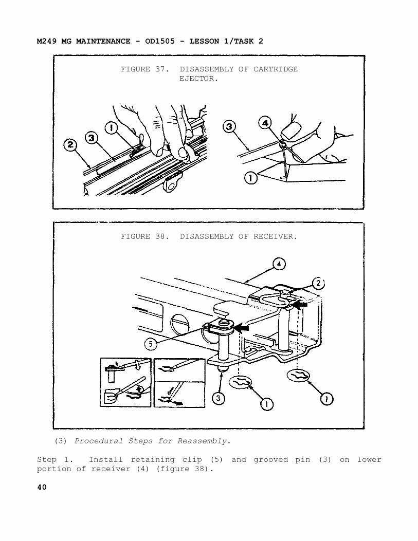
Step 1. Compress retaining clip (1) loose from receiver (2) and lift ejector (3) from receiver (2) (figure 37 on the following page).
Step 2. Remove retaining clip (1) and cartridge ejector pin (4) from cartridge ejector (3) (figure 37).
Step 3. Visually inspect parts for cracks or damage.
Step 4. Replace any unserviceable parts.
Step 5. Remove retaining clip (1) from headed grooved pins (2) and (3) on the rear portion of receiver (4) (figure 38 on the following page).
Step 6. Remove grooved pin assembly (2) from receiver (4) (figure 38).
Step 7. Remove grooved pin (3) and retaining clip (5) (figure 38).
Step 8. Visually inspect parts for cracks or burrs. Replace all unserviceable parts.
39
M249 MG MAINTENANCE - OD1505 - LESSON 1/TASK 2
FIGURE 37. DISASSEMBLY OF CARTRIDGEEJECTOR.
FIGURE 38. DISASSEMBLY OF RECEIVER.
(3) Procedural Steps for Reassembly.
Step 1. Install retaining clip (5) and grooved pin (3) on lower portion of receiver (4) (figure 38).
40
M249 MG MAINTENANCE - OD1505 - LESSON 1/TASK 2
Step 2. Install retaining clip (1) between outerside of flange on lower left hand receiver (4) and retaining clip (5) into groove on headed pin (3) (figure 38 on the previous page).
Step 3. Install grooved pin assembly (2) into receiver (4) and insert retaining clip (1) (figure 38).
Step 4. Install ejector (3) on pin (4) and snap retaining clip (1) over groove of ejector pin with curved end overlapping front part of ejector. Install ejector pin, ejector and retaining clip onto receiver (refer back to figure 37 on the previous page).
Step 5. Compress retaining clip (1) and install ejector assembly (3) into recess of receiver (2) (figure 37). Check for spring tension.
5. Intermediate Direct Support (IDS) Maintenance Procedures
a. Maintenance of Barrel Assembly.
(1) Initial Setup.
(a) Tools and Special Tools. Front sight base adjusting tool; small arms repairman tool kit; spanner wrench front sight post.
(b) Materials/Parts. As required.
(c) Personnel Required. Small arms repairer.
(d) Equipment Condition. Barrel removed.
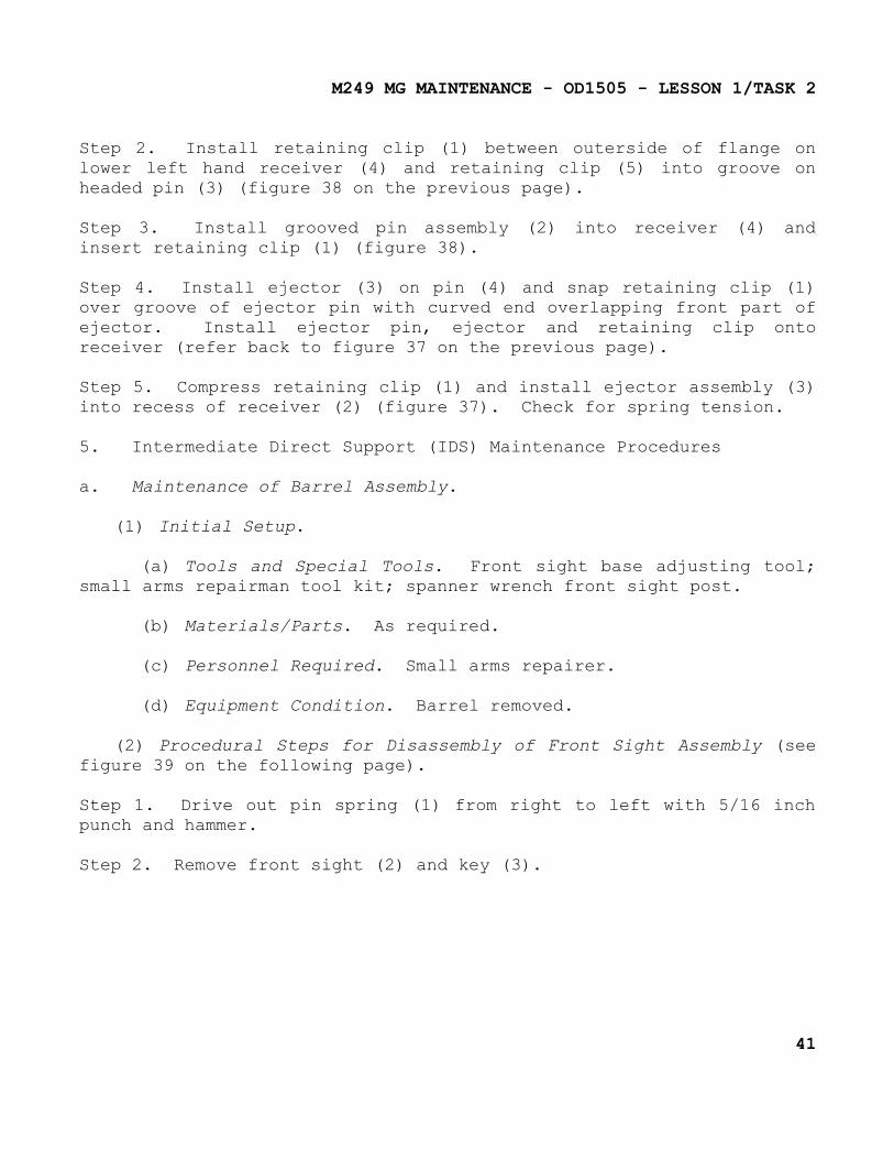
(2) Procedural Steps for Disassembly of Front Sight Assembly (see figure 39 on the following page).
Step 1. Drive out pin spring (1) from right to left with 5/16 inch punch and hammer.
Step 2. Remove front sight (2) and key (3).
41
M249 MG MAINTENANCE - OD1505 - LESSON 1/TASK 2
FIGURE 39. DISASSEMBLY OF FRONT SIGHTASSEMBLY.
NOTE
If replacement parts are required (i.e., new barrel (4) or, new sight (2)), the spring pin (1) must be replaced. The key (3) maintains a rigid position of the front sight on the gas block (5) of the barrel (4).
(3) Procedural Steps for Reassembly of Front Sight Assembly.
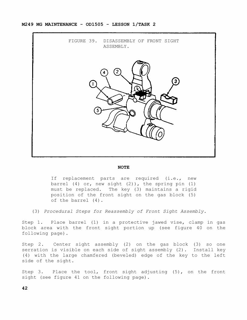
Step 1. Place barrel (1) in a protective jawed vise, clamp in gas block area with the front sight portion up (see figure 40 on the following page).
Step 2. Center sight assembly (2) on the gas block (3) so one serration is visible on each side of sight assembly (2). Install key (4) with the large chamfered (beveled) edge of the key to the left side of the sight.
Step 3. Place the tool, front sight adjusting (5), on the front sight (see figure 41 on the following page).
42
M249 MG MAINTENANCE - OD1505 - LESSON 1/TASK 2
FIGURE 40. REASSEMBLY OF FRONTSIGHT ASSEMBLY.
FIGURE 41. REASSEMBLY OF FRONT SIGHTASSEMBLY (CONTINUED).
Step 4. Push alignment pin (6) in through the sight base and key until it is flush with the inner curvature of the slot in the tool. Tighten two screws (7) snugly to hold tool (5) in place.
Step 5. When the desired adjustment is obtained, place spring pin (8) into the slot of tool (5) and
43
M249 MG MAINTENANCE - OD1505 - LESSON 1/TASK 2
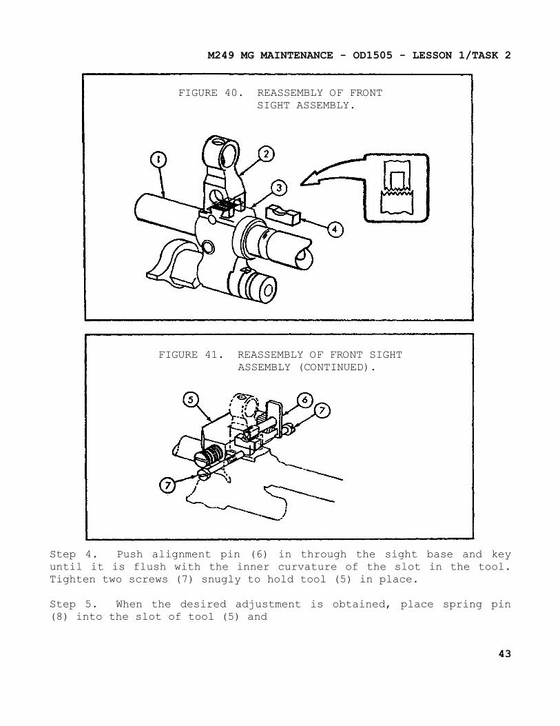
press spring pin (8) into place by turning screw (9) with screwdriver (see figure 42).
Step 6. Loosen the screws, remove the front sight adjusting tool, and then restake the spring pin.
FIGURE 42. REASSEMBLY OF FRONT SIGHTASSEMBLY (CONTINUED).
b. Maintenance of Cover and Feed Mechanism Assembly.
(1) Initial Setup.
(a) Tools and Special Tools. Small arms repairman tool kit; small arms shop set.
(b) Materials/Parts. Inspection penetrant; CLP.
(c) Personnel Required. Small arms repairer.
(d) Equipment Condition. Weapon field stripped (cover removed).
(2) Procedural Steps for Disassembly.
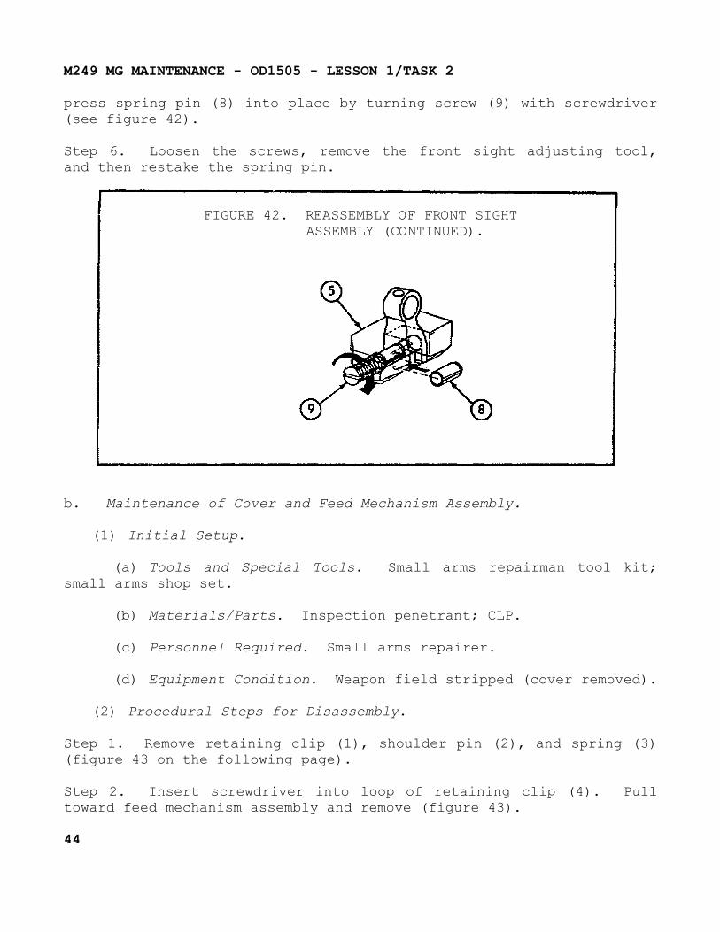
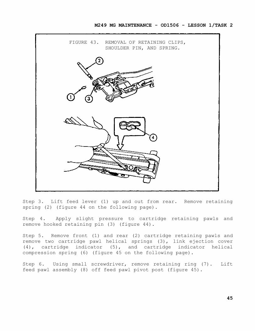
Step 1. Remove retaining clip (1), shoulder pin (2), and spring (3) (figure 43 on the following page).
Step 2. Insert screwdriver into loop of retaining clip (4). Pull toward feed mechanism assembly and remove (figure 43).
44
M249 MG MAINTENANCE - OD1506 - LESSON 1/TASK 2
FIGURE 43. REMOVAL OF RETAINING CLIPS,SHOULDER PIN, AND SPRING.
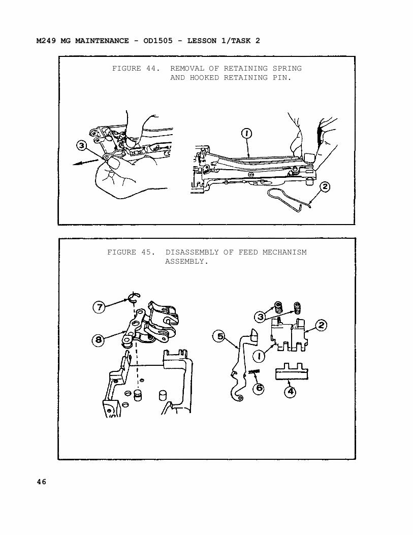
Step 3. Lift feed lever (1) up and out from rear. Remove retaining spring (2) (figure 44 on the following page).
Step 4. Apply slight pressure to cartridge retaining pawls and remove hooked retaining pin (3) (figure 44).
Step 5. Remove front (1) and rear (2) cartridge retaining pawls and remove two cartridge pawl helical springs (3), link ejection cover (4), cartridge indicator (5), and cartridge indicator helical compression spring (6) (figure 45 on the following page).
Step 6. Using small screwdriver, remove retaining ring (7). Lift feed pawl assembly (8) off feed pawl pivot post (figure 45).
45
M249 MG MAINTENANCE - OD1505 - LESSON 1/TASK 2
FIGURE 44. REMOVAL OF RETAINING SPRINGAND HOOKED RETAINING PIN.
FIGURE 45. DISASSEMBLY OF FEED MECHANISMASSEMBLY.
46
M249 MG MAINTENANCE - OD1505 - LESSON 1/TASK 2
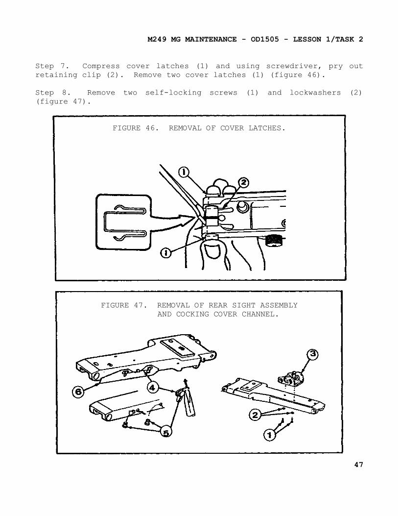
Step 7. Compress cover latches (1) and using screwdriver, pry out retaining clip (2). Remove two cover latches (1) (figure 46).
Step 8. Remove two self-locking screws (1) and lockwashers (2) (figure 47).
FIGURE 46. REMOVAL OF COVER LATCHES.
FIGURE 47. REMOVAL OF REAR SIGHT ASSEMBLYAND COCKING COVER CHANNEL.
47
M249 MG MAINTENANCE - OD1505 - LESSON 1/TASK 2
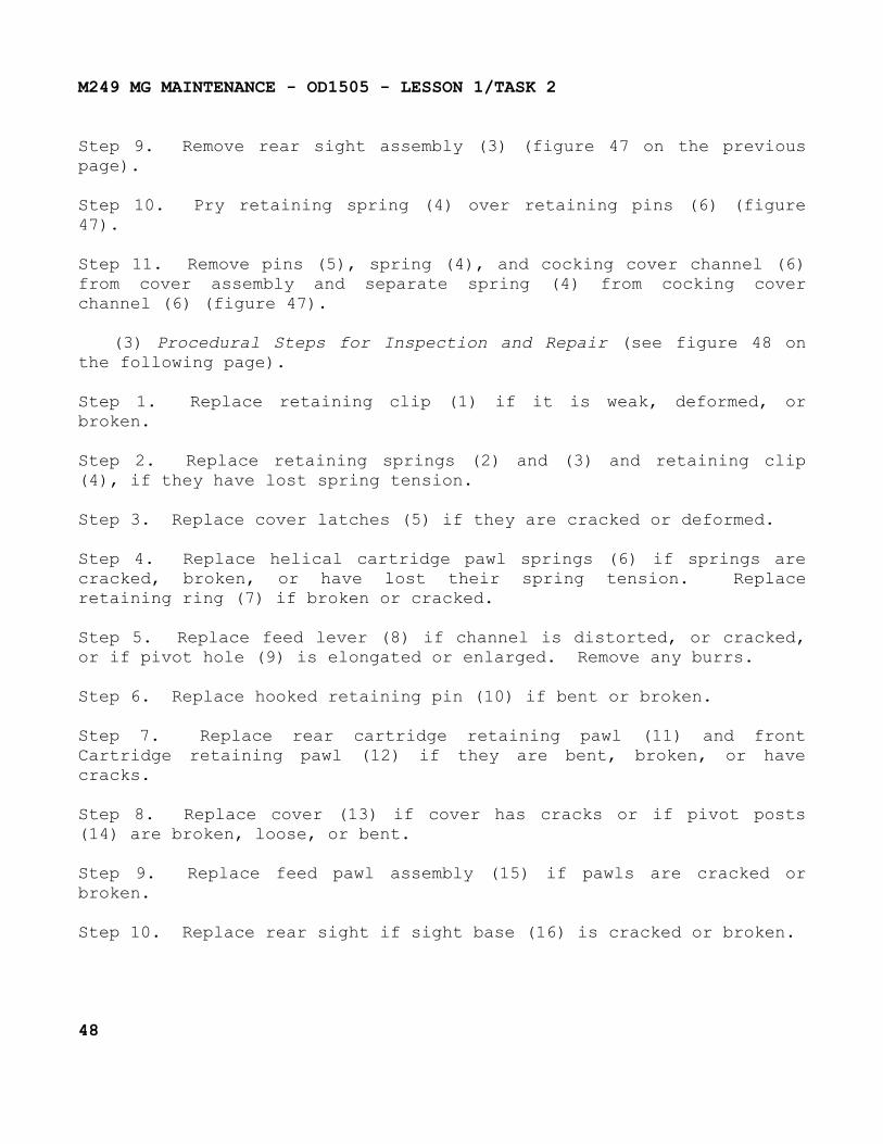
Step 9. Remove rear sight assembly (3) (figure 47 on the previous page).
Step 10. Pry retaining spring (4) over retaining pins (6) (figure 47).
Step 11. Remove pins (5), spring (4), and cocking cover channel (6) from cover assembly and separate spring (4) from cocking cover channel (6) (figure 47).
(3) Procedural Steps for Inspection and Repair (see figure 48 on the following page).
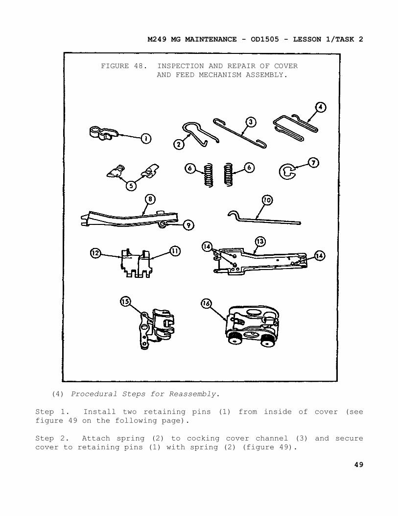
Step 1. Replace retaining clip (1) if it is weak, deformed, or broken.
Step 2. Replace retaining springs (2) and (3) and retaining clip (4), if they have lost spring tension.
Step 3. Replace cover latches (5) if they are cracked or deformed.
Step 4. Replace helical cartridge pawl springs (6) if springs are cracked, broken, or have lost their spring tension. Replace retaining ring (7) if broken or cracked.
Step 5. Replace feed lever (8) if channel is distorted, or cracked, or if pivot hole (9) is elongated or enlarged. Remove any burrs.
Step 6. Replace hooked retaining pin (10) if bent or broken.
Step 7. Replace rear cartridge retaining pawl (11) and front Cartridge retaining pawl (12) if they are bent, broken, or have cracks.
Step 8. Replace cover (13) if cover has cracks or if pivot posts (14) are broken, loose, or bent.
Step 9. Replace feed pawl assembly (15) if pawls are cracked or broken.
Step 10. Replace rear sight if sight base (16) is cracked or broken.
48
M249 MG MAINTENANCE - OD1505 - LESSON 1/TASK 2
FIGURE 48. INSPECTION AND REPAIR OF COVERAND FEED MECHANISM ASSEMBLY.
(4) Procedural Steps for Reassembly.
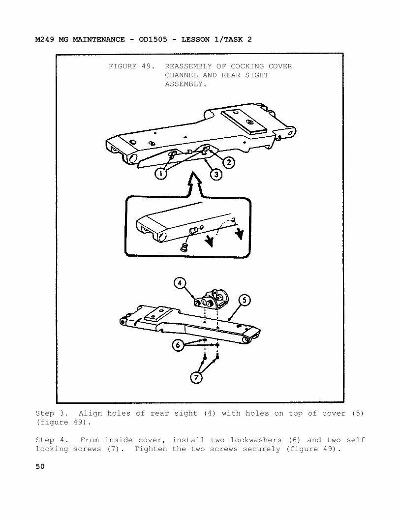
Step 1. Install two retaining pins (1) from inside of cover (see figure 49 on the following page).
Step 2. Attach spring (2) to cocking cover channel (3) and secure cover to retaining pins (1) with spring (2) (figure 49).
49
M249 MG MAINTENANCE - OD1505 - LESSON 1/TASK 2
FIGURE 49. REASSEMBLY OF COCKING COVERCHANNEL AND REAR SIGHTASSEMBLY.
Step 3. Align holes of rear sight (4) with holes on top of cover (5) (figure 49).
Step 4. From inside cover, install two lockwashers (6) and two self locking screws (7). Tighten the two screws securely (figure 49).
50
M249 MG MAINTENANCE - OD1505 - LESSON 1/TASK 2
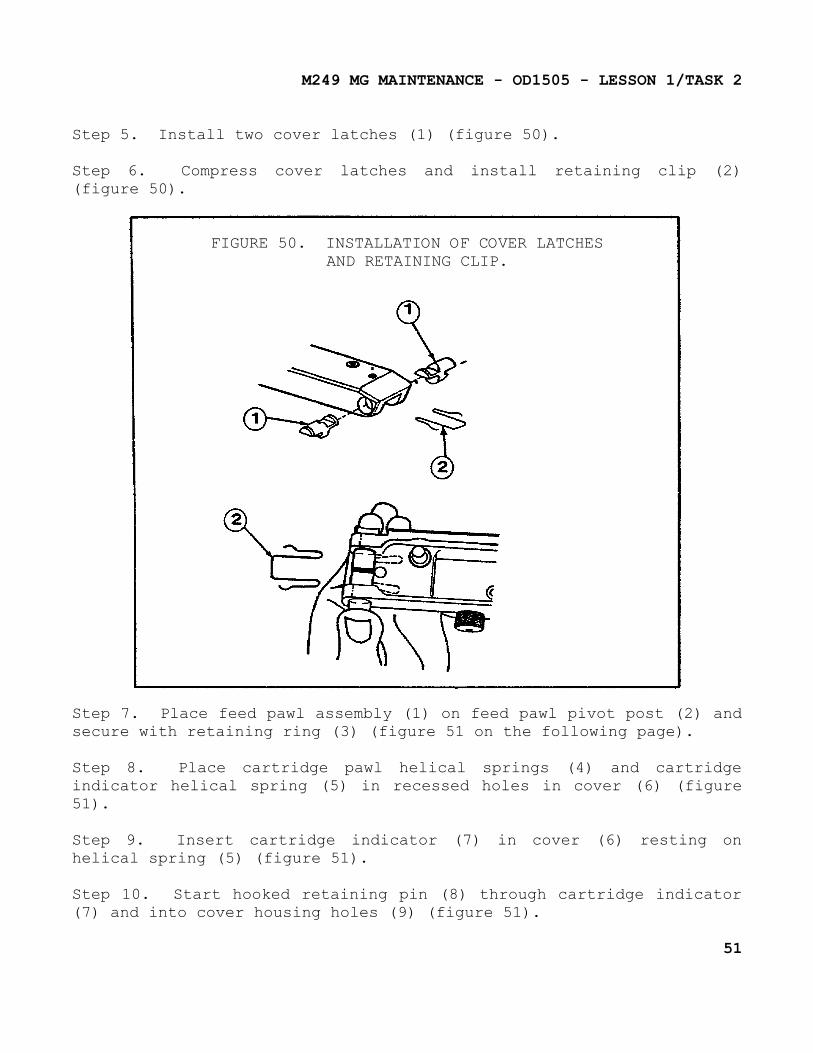
Step 5. Install two cover latches (1) (figure 50).
Step 6. Compress cover latches and install retaining clip (2) (figure 50).
FIGURE 50. INSTALLATION OF COVER LATCHESAND RETAINING CLIP.
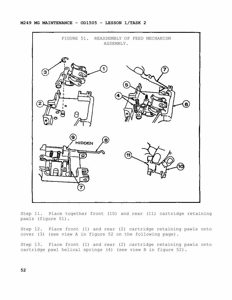
Step 7. Place feed pawl assembly (1) on feed pawl pivot post (2) and secure with retaining ring (3) (figure 51 on the following page).
Step 8. Place cartridge pawl helical springs (4) and cartridge indicator helical spring (5) in recessed holes in cover (6) (figure 51).
Step 9. Insert cartridge indicator (7) in cover (6) resting on helical spring (5) (figure 51).
Step 10. Start hooked retaining pin (8) through cartridge indicator (7) and into cover housing holes (9) (figure 51).
51
M249 MG MAINTENANCE - OD1505 - LESSON 1/TASK 2
FIGURE 51. REASSEMBLY OF FEED MECHANISMASSEMBLY.
Step 11. Place together front (10) and rear (11) cartridge retaining pawls (figure 51).
Step 12. Place front (1) and rear (2) cartridge retaining pawls onto cover (3) (see view A in figure 52 on the following page).
Step 13. Place front (1) and rear (2) cartridge retaining pawls onto cartridge pawl helical springs (4) (see view B in figure 52).
52
M249 MG MAINTENANCE - OD1505 - LESSON 1/TASK 2
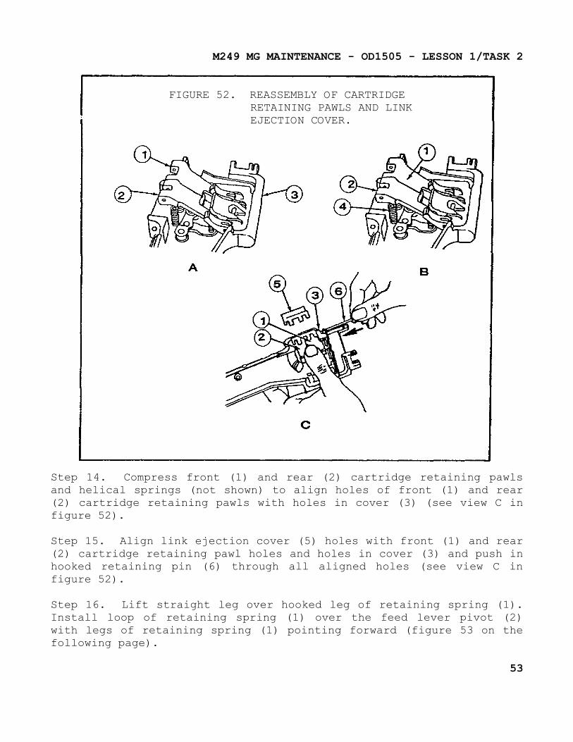
FIGURE 52. REASSEMBLY OF CARTRIDGERETAINING PAWLS AND LINKEJECTION COVER.
Step 14. Compress front (1) and rear (2) cartridge retaining pawls and helical springs (not shown) to align holes of front (1) and rear (2) cartridge retaining pawls with holes in cover (3) (see view C in figure 52).
Step 15. Align link ejection cover (5) holes with front (1) and rear (2) cartridge retaining pawl holes and holes in cover (3) and push in hooked retaining pin (6) through all aligned holes (see view C in figure 52).
Step 16. Lift straight leg over hooked leg of retaining spring (1). Install loop of retaining spring (1) over the feed lever pivot (2) with legs of retaining spring (1) pointing forward (figure 53 on the following page).
53
M249 MG MAINTENANCE - OD1505 - LESSON 1/TASK 2
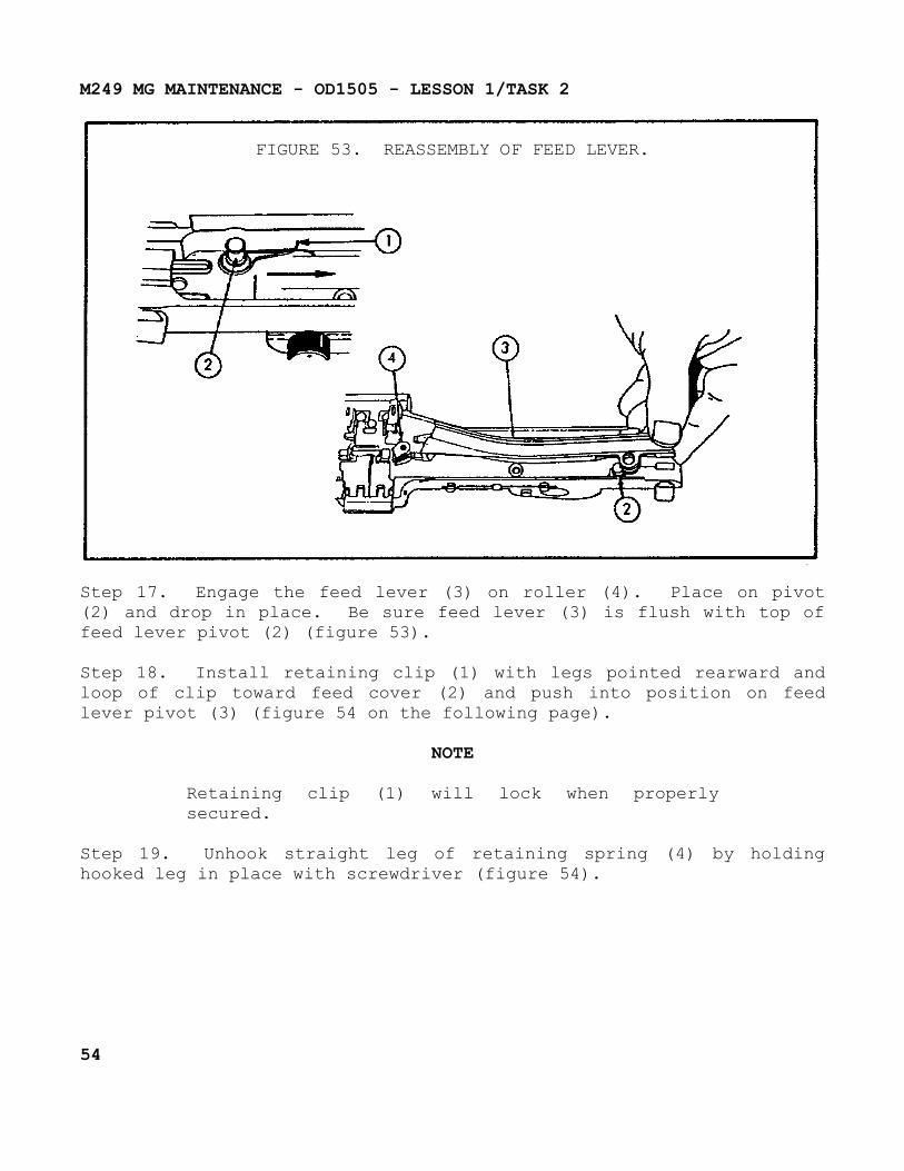
FIGURE 53. REASSEMBLY OF FEED LEVER.
Step 17. Engage the feed lever (3) on roller (4). Place on pivot (2) and drop in place. Be sure feed lever (3) is flush with top of feed lever pivot (2) (figure 53).
Step 18. Install retaining clip (1) with legs pointed rearward and loop of clip toward feed cover (2) and push into position on feed lever pivot (3) (figure 54 on the following page).
NOTE
Retaining clip (1) will lock when properly secured.
Step 19. Unhook straight leg of retaining spring (4) by holding hooked leg in place with screwdriver (figure 54).
54
M249 MG MAINTENANCE - OD1505 - LESSON 1/TASK 2
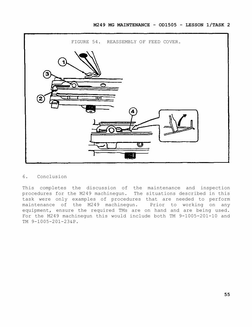
FIGURE 54. REASSEMBLY OF FEED COVER.
6. Conclusion
This completes the discussion of the maintenance and inspection procedures for the M249 machinegun. The situations described in this task were only examples of procedures that are needed to perform maintenance of the M249 machinegun. Prior to working on any equipment, ensure the required TMs are on hand and are being used. For the M249 machinegun this would include both TM 9-1005-201-10 and TM 9-1005-201-23&P.
55
M249 MG MAINTENANCE - OD1505 - LESSON 1/PE 1
PRACTICAL EXERCISE 1
1. Instructions
Read the scenario and respond to the requirements that follow the scenario.
2. Scenario
SSG Thatcher is an instructor in the Artillery Branch of the Weapons Department. After 2 years of instructing in this branch, he has been informed that as of Monday he will be teaching the M249 machinegun, which is in the Small Arms Branch of the same department. Being unfamiliar with small arms after so many years of teaching artillery, he decides to give himself a sample test to see how much he really knows about the M249 machinegun.
3. Requirement
Below is a list of questions he feels will give him a general knowledge of the operation and maintenance of the M249 machinegun.
a. What is the purpose of the butt stock and shoulder assembly?
b. What is the rate of fire of the M249 machinegun when it is set on MAX?
c. What is the first step that should be performed when loading the machinegun?
d. What condition exists when a live round is stuck in the weapon?
e. How would a runaway machinegun be described?
f. What three components make up the operating rod assembly?
g. What part of the machinegun must be removed before removing the bipod?
h. What is used to clean the bore of the barrel when heavy deposits are present?
56

M249 MG MAINTENANCE - OD1505 - LESSON 1/PE 1
i. When checking the driving spring for broken strands, unit maintenance would be notified if how many strands on the same coil of the spring were broken?
j. What tool is used to tighten the machine bolt of the trigger mechanism during reassembly?
k. When inspecting the cover and feed mechanism assembly, the retaining clip would be replaced if it was _________________________.
57
M249 MG MAINTENANCE - OD1505 - LESSON 1/PE 1
LESSON 1. PRACTICAL EXERCISE - ANSWERS
1. Requirement
a. The butt stock and shoulder assembly serves as a shoulder support for aiming and firing the machinegun. It also contains a folding shoulder rest.
b. The max rate of fire is 1000 rds/min.
c. The first step is to charge the weapon.
d. A live round is stuck when the round did not fire and did not extract.
e. A runaway machinegun can be described as a machinegun that won't stop firing.
f. The three components that make up the operating rod assembly are a spring, a guide rod, and a buffer.
g. The gas cylinder must be removed.
h. The bore of the barrel is cleaned with a bore brush.
i. Unit maintenance would be notified if more than one strand was broken.
j. The 11mm end of a box spanner tool, and a screwdriver or punch, are used to tighten the machine bolt.
k. weak, deformed, or broken.
58

M249 MG MAINTENANCE - OD1505 - REFERENCES
REFERENCES
59

M249 MG MAINTENANCE - OD1505 - REFERENCES
REFERENCES
The following documents were used as resource materials in developing this subcourse:
TM 9-1005-201-10TM 9-1005-201-23&P
60