maintenance manual - varco st-80 roughneck (2)
TRANSCRIPT
ST-80ST-80
SM00995
RoughneckService Manual

3
4
General Information
Specifications
Maintenance
Troubleshooting
1
2

3
4
General Information
Specifications
Maintenance
Troubleshooting
1
2

1
General Information
1-1
3
4
General Information
1
2
Preface................................................................ 1-3
Manual conventions ...................................................... 1-3
Note ................................................................................... 1-3Caution .............................................................................. 1-3Warning ............................................................................. 1-3
Product bulletins ............................................................ 1-3
Overall equipment safety requirements ......................... 1-3
Personnel training.............................................................. 1-4Systems safety practices ................................................... 1-4
Hydraulic systems and components ............................ 1-4General safety ................................................................... 1-5
Equipment motion hazards 1-5Proper use of equipment .............................................. 1-6
Tool orientation .................................................. 1-7
ST-80 general information .................................. 1-8
ST-80 carriage assembly .............................................. 1-9
Pedestal assembly ........................................................ 1-10
ST-80 wrench assembly ................................................ 1-11
Control System .............................................................. 1-12
Operating the ST-80............................................ 1-14
Making and breaking connections ................................. 1-14
Adjusting the makeup torque ......................................... 1-16
Adjusting the stabbing guide ......................................... 1-17
Adjusting torque gauge responsiveness........................ 1-18
Storing the ST-80 ................................................ 1-19

1
General Information
1-2
3
4
5
General Information
1
2
1
General Information
1-3
Preface
Manual conventions
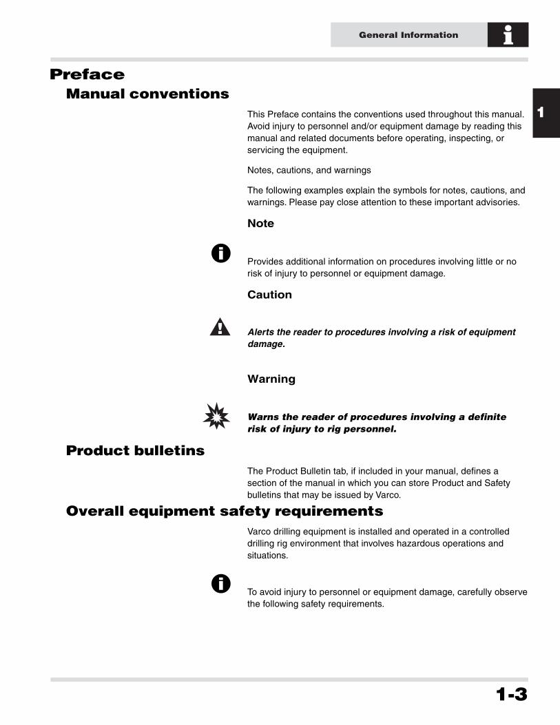
This Preface contains the conventions used throughout this manual.Avoid injury to personnel and/or equipment damage by reading thismanual and related documents before operating, inspecting, orservicing the equipment.
Notes, cautions, and warnings
The following examples explain the symbols for notes, cautions, andwarnings. Please pay close attention to these important advisories.
Note
i Provides additional information on procedures involving little or norisk of injury to personnel or equipment damage.
Caution
! Alerts the reader to procedures involving a risk of equipmentdamage.
Warning
Warns the reader of procedures involving a definite
risk of injury to rig personnel.
Product bulletins
The Product Bulletin tab, if included in your manual, defines asection of the manual in which you can store Product and Safetybulletins that may be issued by Varco.
Overall equipment safety requirements
Varco drilling equipment is installed and operated in a controlleddrilling rig environment that involves hazardous operations andsituations.
i To avoid injury to personnel or equipment damage, carefully observethe following safety requirements.
1
General Information
1-4
Personnel training
All personnel installing, operating, repairing, or maintainingequipment, or those in the vicinity of this equipment, should betrained in rig safety, tool operation, and maintenance as applicable.This measure helps ensure the safety of everyone exposed to theequipment for whatever purpose.
i During installation, operation, maintenance, or repair of thisequipment, personnel should wear protective equipment.
Contact the Varco Service Department to arrange for training forequipment operation and maintenance.
Systems safety practices
The equipment covered by this manual may require or contain oneor more utilities such as electrical, hydraulic, and cooling water.
i Before installing or performing maintenance or repairs on theequipment, read the following instructions to avoid endangeringexposed persons or damaging equipment.
❏ Isolate all energy sources before beginning work.
❏ Avoid performing maintenance and repairs while theequipment is in operation.
❏ Wear proper protective equipment during the installation,maintenance, or repair of this equipment.
Hydraulic systems and components
Hydraulic systems and components are designed for specific use inthe drilling industry. The hydraulic pressure for this equipment canbe as high as 3,000 psi.
❏ Before beginning work on any portion of the hydraulic system,familiarize yourself with the hydraulic and electricalschematics.
❏ Isolate, lock out, and tag the hydraulic and electrical powerand controls.
❏ Take precautions when bleeding down residual systempressure, using bleed valves or equivalent techniques.
1
General Information
1-5
Hydraulic fluids can be extremely hot and under high
pressure.
❏ Properly discharge all system accumulators.
❏ Collect all residual hydraulic fluid in a container to prevent rig orenvironmental contamination.
❏ Take precautions to prevent hydraulic oil from leaking into otheropen electrical or mechanical components, such as junctionboxes.
Pneumatic systems and components
Pneumatic systems and components are designed for specific usein the drilling industry. The pneumatic pressure for this equipmentcan be as high as 150 psi.
❏ Prior to beginning work on any portion of the pneumatic system,familiarize yourself with the pneumatic and electricalschematics.
❏ Isolate, lock out, and tag the pneumatic and electrical power andcontrols.
❏ Take precautions when bleeding down residual system pressureusing bleed valves or equivalent techniques.
❏ Properly discharge all system accumulators.
General safety
Equipment motion hazards
Some of the Varco equipment travels either horizontally, vertically onrails, or both.
i Avoid placing objects in or near the path of motion for thisequipment. Such interference could cause personnel to be trappedor crushed by equipment.
i Keep the working envelope/zone of the equipment free frompersonnel.
1
General Information
1-6
When replacing components
❏ During disassembly and reassembly of any equipment, verifyall components such as cables, hoses, etc. are tagged andlabeled to ensure reinstalling the components correctly.
❏ Replace failed or damaged components with Varco certifiedparts. Failure to do so could result in a hazard, equipmentdamage, or personal injury.
During routine maintenance
Equipment must be maintained on a regular basis. See the body ofthe service manual for maintenance recommendations.
i Failure to conduct regular maintenance can result in a hazard,equipment damage, or injury to personnel.
Visibility of equipment operation
Clear, unobstructed visibility of all equipment functions is critical tosafe operation. Do not block or impair the equipment operator’sfield of view. In cases where this is not possible, the customer mustinstall video cameras to ensure adequate visibility.
Proper use of equipment
Varco equipment is designed for specific functions and applicationsand should be used only for the intended purpose.
i Do not hoist personnel using this equipment.
Contact the Varco service center for questions regarding equipmentoperation, maintenance, hazards, and designed function.

1
General Information
1-7
Tool orientation
FrontLeft
Rear Right
1
General Information
1-8
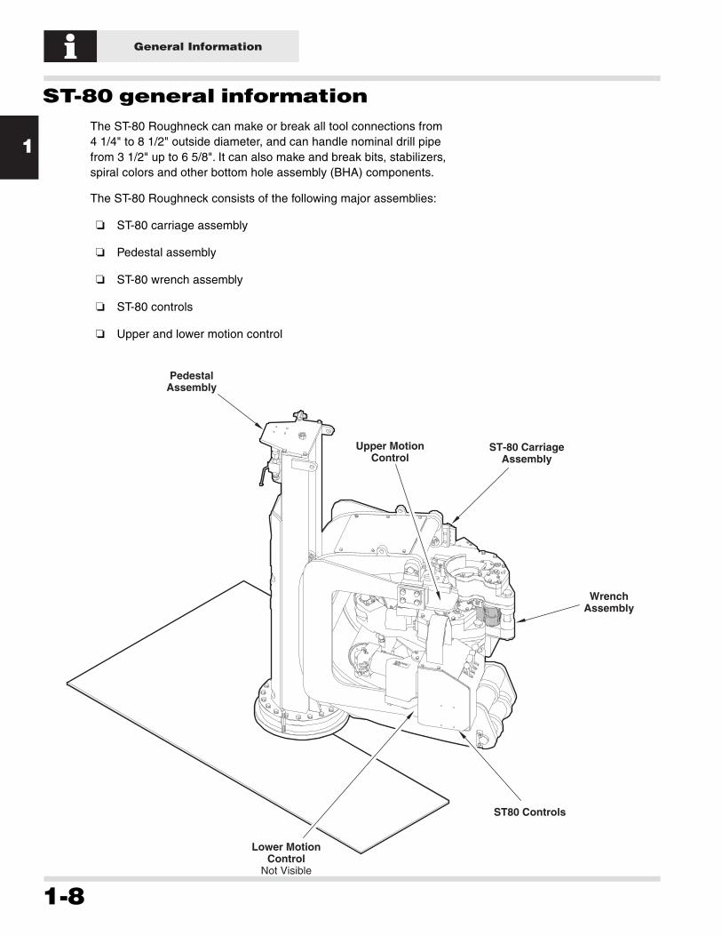
ST-80 general information
The ST-80 Roughneck can make or break all tool connections from4 1/4" to 8 1/2" outside diameter, and can handle nominal drill pipefrom 3 1/2" up to 6 5/8". It can also make and break bits, stabilizers,spiral colors and other bottom hole assembly (BHA) components.
The ST-80 Roughneck consists of the following major assemblies:
❏ ST-80 carriage assembly
❏ Pedestal assembly
❏ ST-80 wrench assembly
❏ ST-80 controls
❏ Upper and lower motion control
ST-80 CarriageAssembly
Upper MotionControl
Lower MotionControl
Not Visible
WrenchAssembly
ST80 Controls
PedestalAssembly

1
General Information
1-9
ST-80 general information
ST-80 carriage assembly
The carriage assembly can move vertically to position the ST-80properly at the tool joint.
HydraulicManifoldStabbing
Guide
WrenchAssembly
Carriage
Controls
1
General Information
1-10
ST-80 general information
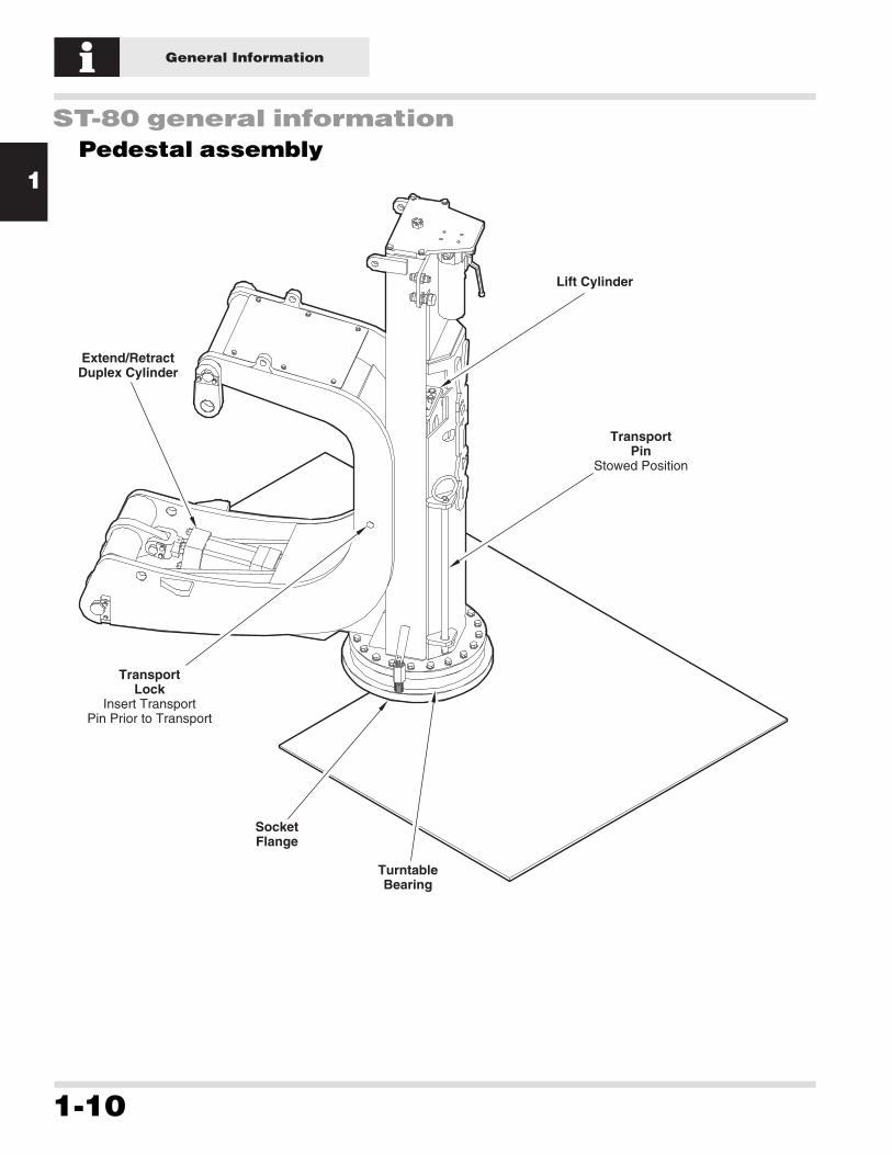
Pedestal assembly
Lift Cylinder
TransportPin
Stowed Position
TransportLock
Insert TransportPin Prior to Transport
Extend/RetractDuplex Cylinder
SocketFlange
TurntableBearing

1
General Information
1-11
ST-80 general information
ST-80 wrench assembly
The ST-80 uses a combination spinning and torque wrench. Thedies of the upper jaws are located in between the spinner rollers.The spinner rollers grip the pipe and spin in connections with atorque of 1,750 ft lb.
After spinning, the torque wrench can torque the connection with amaximum torque of 60,000 ft lb. The wrench can break outconnections with a maximum torque of 80,000 ft lb.
Upper JawDies
1 each side
Lower Dieand Die Holder
1 each side
Spin Rollers2 each side

1
General Information
1-12
ST-80 general information
Control System
The ST-80 controls are mounted on the carriage. They include thefollowing:
❏ JAWS: UN-CLAMP, CLAMP. Clamps or unclamps the wrenchon a tubular.
❏ MODE: SPIN, TORQUE. Determines whether the wrenchspins or torques connections. The operator must hold thiscontrol in the desired postion while performing theseoperations.
❏ TORQUE: MAKE, BREAK. Determines whether the wrenchmakes or breaks connections.
❏ SPIN: IN, OUT. Determines whether the wrench spins in orout.
❏ ST-80: UP, DOWN. Adusts the vertical height of the ST-80.
❏ ADJUST: EXTEND, RETRACT. Adjusts the travel distance ofthe ST-80 when extending or retracting the tool.
❏ ST-80: EXTEND, RETRACT. Selects whether the tool extendsor retracts.

1
General Information
1-13
ST-80 general information
JawsClamp, Unclamp
ModeSpin, Torque
TorqueMake, Break
SpinIn, Out
TorqueGage
ST-80Up, Down
AdjustExtend, Retract
ST-80Extend, Retract

1
General Information
1-14
Operating the ST-80
Making and breaking connections
!Before operating the ST-80 for the first time, be sure to remove the transport pin.
1. Completely extend the tool using the ST-80 EXTEND/ RETRACT control.
2. Adjust the vertical position of the wrench on the connection using ST-80 UP/DOWN control.
3. Use the ADJUST control to precisely position the ST-80 horizontally. The correct position is when the lower guide plate contacts the tubular. This is typically adjusted only once per trip.
ST-80Up, Down
AdjustExtend, Retract
ST-80Extend, Retract
TubularPin
TubularBox
Rollers4 places
Vertical Adjustment

1
General Information
1-15
Operating the ST-80
Making and breaking connections
iIf the wrench does not reach the desired value in one stroke, recycle the torque wrench and repeat steps 4 and 5.
UN-CLAMP
JAWS
CLAMP
SPIN
MODE
TORQUE
MAKE
TORQUE
BREAK
IN
SPIN
OUT
UN-CLAMP
JAWS
CLAMP
SPIN
MODE
TORQUE
MAKE
TORQUE
BREAK
IN
SPIN
OUT
1 Clamp the jaws on the tubular.
Making Connections
2 Hold the MODE control in the SPIN position.
3 SPIN the connection IN.
4 Hold the MODE control in the TORQUE position.
5 Hold the TORQUE control in the MAKE position until the desired torque is achieved.
6 UN-CLAMP the jaws and recycle the torque wrench to prepare for the next connection.
6 UN-CLAMP the jaws and recycle the torque wrench to prepare for the next break.
1
26
1
6
35
Hold
4
Hold
4
Hold
1 Clamp the jaws on the tubular.
Breaking Connections
2 Hold the MODE control in the TORQUE position.
3 Hold the TORQUE control in the BREAK position until the connection is broken.
4 Hold the MODE control in the SPIN position.
5 SPIN the connection OUT.2 3 5
Hold

1
General Information
1-16
Operating the ST-80
Adjusting the makeup torque
i
!
PRV Adjustment Knob
Torque Gauge
Reference Indicator
Use the following procedure to adjust the ST-80 make up torque:1. Back the adjustment knob on the pressure reducing valve (PRV) all of the way out.
Turning the PRV adjustment knob counter clockwise decreases torque. Turning the PRV adjustment knob clockwise increases the torque.
2. Clamp onto a tubular.3. Spin the connection in.4. Torque the connection. 5. While holding the torque, turn the PRV adjustment knob clockwise while watching the torque gauge until the desired torque is achieved.
Do not adjust the torque if one of the torque cylinders is at its end of stroke.
6. Position the reference indicator (red needle) on the torque gauge at the desired torque value.

1
General Information
1-17
Operating the ST-80
Adjusting the stabbing guide
Use the following procedure to adjust the stabbing guide:
1. Use the horizontal travel and vertical travel controls to positionthe torque wrench on the tool joint box.
2. Clamp onto the tubular.
3. Stab the next stand.
4. Loosen two adjusting nuts and align the inside edge of thestabbing guide with the outer circumference of the pipe. Tightenthe nuts.
i When coming out of the hole or when handling drill collars, unscrewthe front nuts and push the guide back, out of the way.
Stabbing Guide
Adjusting Nuts
1
General Information
1-18
Operating the ST-80
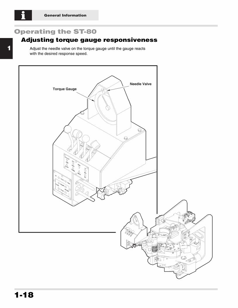
Adjusting torque gauge responsiveness
Adjust the needle valve on the torque gauge until the gauge reactswith the desired response speed.
Torque GaugeNeedle Valve

1
General Information
1-19
Storing the ST-80
Palletize the ST-80 for indoor storage. A cargo container isappropriate for indoor or outdoor storage.
Avoid wide temperature and humidity variations. The idealenvironment for storing the ST-80 is clean and dry with an ambienttemperature of 60°F (16°C). If high humidity is unavoidable, Varcorecommends storing the ST-80 at 70°F (21°C).
All exposed, unpainted metal surfaces are coated with rustpreventive at the factory prior to shipment. Coat all unpainted metalsurfaces with rust preventive prior to storage or transport.
Cover all openings to prevent water or dust from entering. Varcodoes not recommend using silica or dehydrating agents.
When the ST-80 is not being used for more than 3 months, performthe following:
1. Clean the ST-80.
2. Grease the ST-80 as described in the Maintenance section ofthis manual.
3. Clean and cap all hydraulic quick disconnects (QDs).
i Varco recommends Kendall Grade 5 (GE-D6C6A1) rust preventive,or an equivalent.
! Replace the shipping pin prior to storage and/or moving theST-80.

1
General Information
1-20
2
Specifications
2-1
3
4
Specifications
1
2
General specifications ....................................... 2-3
Hydraulic requirements ................................................. 2-4
Wrench assembly .......................................................... 2-4
Shipping data (approx., allowing for crate/palette) ........ 2-4

2
Specifications
2-2
3
4
1
Specifications
2
2
Specifications
2-3
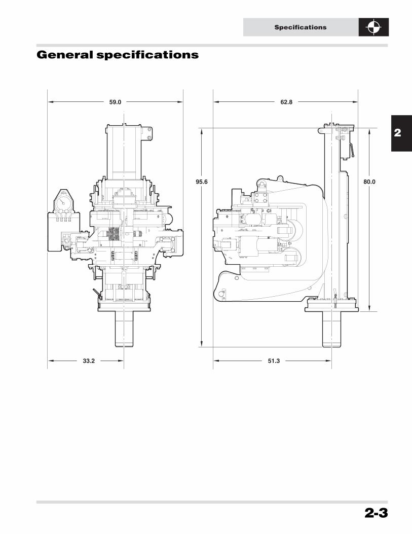
General specifications
62.8
51.333.2
95.6 80.0
59.0

2
Specifications
2-4
General specifications
Hydraulic requirements
Hydraulic operating pressure (max.) 2,600 psi
Hydraulic operating pressure (min.) 2,000 psi
Hydraulic flow rate required (min.) 28 gpm @ 1000 psi
Hydraulic flow rate required (max.) 40 gpm (150 l/min)
Supply connections (min.) 1" JIC
Return connections 1 1/4" JIC
Wrench assembly
Motor spinning roller ratio 2:1
Spin speed (rollers) 190 rpm
Spin speed (8 1/2" pipe) 90 rpm
Make up torque 60,000 ft lb max.
Break out torque 80,000 ft lb max.
Shipping data (approx., allowing for crate/palette)
Height 88"
Width 60"
Depth 65"
Weight 6,800 lb

3
Maintenance
3-1
3
4
Maintenance
1
2
Lubricant specifications..................................... 3-3
Selecting a lubricant ...................................................... 3-3
Recommended general lubricants..................................... 3-3Recommended hydraulic fluids ......................................... 3-3
Inspection and lubrication ................................. 3-4
Inspecting hardware and fittings .................................... 3-4
Lubricating the ST-80 .................................................... 3-4
Disassembly and assembly ................................ 3-6
Precautions ................................................................... 3-6
Changing dies ............................................................... 3-7

3
Maintenance
3-2
3
4
Maintenance
1
2

3
Maintenance
3-3
Lubricant specifications
Selecting a lubricant
Use the following two tables to select the appropriate lubricant foryour specific application.
Recommended general lubricants
Above -20˚ C(Above -4˚ F)
Below -20˚ C(Below -4˚ F)
MP Grease
Avi-Motive
Lidok EP2
Gulf Crown EP32
Mobilux EP2
Alvania EP2
Uniway EP2N
Multifak EP2
Multis EP2
Unoba EP2
2
N/R
Avi-Motive W
Lidok EP1
Gulf Crown EP31
Mobilux EP1
Alvania EP1
Uniway EP1N
Multifak EP1
Multis EP1
Unoba EP1
1
Ambient Temperature Range
Manufacturer
Viscosity Index
Castrol
Chevron
Exxon
Gulf
Mobil
Shell
Statoil
Texaco
Total
Union
NGLI
Recommended hydraulic fluids
Hyspin AWS-46
AW Hyd oil 46
Nuto H46
Harmony 46AW
DTE 25
Tellus 46
Hydraway HMA 46
Rando oil HD46
Azolla ZS 46
Unax AW46
46
Hyspin AWS-32
AW Hyd oil 32
Nuto H32
Harmony 32AW
DTE 24
Tellus 32
Hydraway HMA 32
Rando oil HD32
Azolla ZS 32
Unax AW32
32
-10˚ to 85˚ C(14˚ to 185˚ F)
-15˚ to 75˚ C(5˚ to 167˚ F)
Oil Temperature Range
Manufacturer
Viscosity Index
Castrol
Chevron
Exxon
Gulf
Mobil
Shell
Statoil
Texaco
Total
Union
ISO Viscosity Grade

3
Maintenance
3-4
Inspection and lubrication
Inspecting hardware and fittings
Visually inspect the ST-80 for loose or missing hardware andfittings daily. Make sure all safety wire is undamaged.
Check the inline pressure filter daily. Replace as necessary if theindicator is red.
Lubricating the ST-80
The lubrication intervals described in this manual are based onlubricant supplier recommendations. Severe conditions such asextreme loads or temperature, corrosive atmosphere, etc., mayrequire more frequent lubrication.
Worn bushings, binding parts, rust accumulations, and otherabnormal conditions indicate more frequent lubrication isnecessary. Be careful not to over lubricate parts. For example, toomuch grease forced into a fitting can pop out a bearing seal. Overlubrication can also affect safety since over lubricated parts candrip, creating a potential slipping hazard for personnel.
Apply grease daily to all grease fittings as shown on the followingpage.

3
Maintenance
3-5
Inspection and lubrication
Daily
Daily
GreaseFitting
1 each side
Daily
Inline PressureFilter
Replace if indictor is red
Daily
GreaseFitting
1 each side
Daily
Motion ControlBrush mating surfaces
with grease
Daily
GreaseFitting
2 each side
GreaseFitting
1 each side
Daily
GreaseFitting
Daily
GreaseFitting
1 each side

3
Maintenance
3-6
Disassembly and assembly
Precautions
! Only authorized Varco repair technicians should perform thefollowing major disassembly and assembly procedures.
! Transport hydraulic components to a clean, dust-free servicearea before disassembling for service.
i Disassembly pr ocedur es ar e usually per for med when r eplacingdamaged components that ar e causing a tool function to fail.Whenever per for ming a disassembly , practice pr eventivemaintenance by:
❏ Cleaning and inspecting all disassembled parts.
❏ Replacing all worn and damaged parts before they can causeanother failure.
❏ Installing thread protectors on exposed threads.
! Torque all fasteners to the limits given in DS 00008 (DesignSpecification Design T orque Standar d) unless an alter native tor quevalue is given in the pr ocedur e.
Release all hydraulic oil pressure before
disconnecting hydraulic lines. Hydraulic oil under
pressure can penetrate skin and cause serious injury.
Before opening the hydraulic system, thoroughly clean
the work area, and maintain system cleanliness by
promptly capping all disconnected lines. Dirt is
extremely harmful to hydraulic system components
and can cause equipment failure and subsequent
injury to personnel.

3
Maintenance
3-7
Disassembly and assembly
Changing dies
!
CarriageAssembly
Die Holder1 each side
Set Screw2 each side
Screw2 each side
LowerDie
1 each side
Screw2 each side
UpperDie
1 each side
Use the following procedure to replace upper and lower dies:
Replacing upper dies1. Remove the 2 screws holding each die.
Replacing lower dies1. Remove the 2 screws on each die holder.2. Screw in the set screws forcing the die holder out.3. The die will now slid from the die holder.
Caution the die can slip out of the die holder once its free of the housing.

3
Maintenance
3-8
4
Troubleshooting
4-1
3
4
Troubleshooting
1
2
Troubleshooting the ST-80 ................................. 4-3
Theory of operation ....................................................... 4-4

4
Troubleshooting
4-2
3
4
Troubleshooting
1
2

4
Troubleshooting
4-3
Troubleshooting the ST-80
i When testing the ST -80 without pipe , reduce the o verall pressuresetting to 250 psi.
Make sure all hydraulic lines are isolated and the ball
valve is closed before ANY work is carried out on the
ST-80.
When troubleshooting the ST-80, make sure the hydrualic pressureis between 2,000 and 2,600 psi at the inlet of the manifold. Checkthe back pressure of the tank line (make sure the pressure does notexceed 30 psi).
Make sure that all hoses and QDs are properly connected.
Check to see if oil leakage is visible at the manifold, QDs or hoses.
Make sure the tool is lubricated per the Maintenance section of thismanual.
Refer to the theory of operation and schematic whentroubleshooting specific ST-80 components or functions.

4
Troubleshooting
4-4
Troubleshooting the ST-80
Theory of operation
(((TBD Engineering will supply when Hydraulic Schematic isreleased)))

4
Troubleshooting
4-5
Troubleshooting the ST-80
(((TBD Hydraulic Schematic in revision)))

4
Troubleshooting
4-6