magnetic properties of ising thin films with decorated ferrimagnetic surfaces
TRANSCRIPT
Physica B 245 (1998) 233—245
Magnetic properties of Ising thin films with decoratedferrimagnetic surfaces
T. KaneyoshiDepartment of Natural Science Informatics, School of Informatics and Sciences, Nagoya University,
464-01, Nagoya, Japan
Received 18 December 1996; received in revised form 6 May 1997; accepted 13 October 1997
Abstract
The effect of spin-S (S'12) atoms decorated at the surfaces on the magnetic properties of a spin-1
2Ising ferromagnetic
thin film is studied within the framework of effective-field theory with correlations. In particular, the case that decoratedatoms at the surfaces are ordered ferrimagnetically is examined. We find many characteristic phenomena, such as thepossibility of two compensation points, induced by the increase of the layer thickness. ( 1998 Elsevier Science B.V. Allrights reserved.
Keywords: Ising thin film; Ferrimagnetism
1. Introduction
Decorated Ising models, which were originallyintroduced in the literature by Syozi [1], have beenstudied many years ago as the models exhibitingferrimagnetism. The arrangement of atoms was likethat in the normal spinel. Very recently, the decor-ated ferrimagnetic Ising systems with a finite (espe-cially negative) crystal-field interaction constantD [2,3] have received renewed interest on the basisof Ising spin identities and differential operatortechnique. In these works, the exact expression forevaluating the compensation temperature ¹
COMPhas been obtained for spin-1
2systems with decor-
ated spin-S (S'12) atoms. It has been clarified that
there exists a possibility of finding two compensa-tion points in the decorated ferrimagnetic systems,
depending on the values of S and D. In particular,the possibility has been found for a negative valueof D in contrast with that of Ref. [4] for the case ofD"R. Futhermore, the surface magnetic proper-ties of a semi-infinite spin-1
2Ising ferromagnet with
a decorated ferrimagnetic surface have been dis-cussed and many characteristic phenomena are ob-tained in Ref. [5].
On the other hand, great attention has been paidto the magnetic properties of thin films. Becauseof the recent advances of modern vacuum science,such as expitaxial growth techniques, it is nowpossible to grow very thin magnetic films witharbitrary thickness and this has stimulated renewedinterest in both experimental and theoretical filmmagnetism. From the theoretical point of view, theIsing model has been frequently and successfully
0921-4526/98/$19.00 ( 1998 Elsevier Science B.V. All rights reservedPII S 0 9 2 1 - 4 5 2 6 ( 9 7 ) 0 0 8 7 9 - X
adopted for the description and understanding ofmany characteristic features of thin magnetic films.These theoretical works deal mainly with ferro-magnetic thin films [6—11]. Furthermore, ferrima-gnetically ordered thin films have been producedexperimentally for technological applications suchas medium for magnetooptic memories [12]. Theexistence of a compensation point in such a thinfilm is important for recording memories. Onlya few theoretical works have made contact with thestudy of ferrimagnetic thin film [13]. As far as weknow, however, the Ising thin films with decoratedmagnetic atoms at the surfaces have not been inves-tigated, although thin ferromagnetic films withalloying-type ferrimagnetic surfaces have beenstudied and the possibility of many compensationpoints are pointed out in Ref. [14]. In fact, thesurfaces of magnetic thin films are usually not cleanexperimentally and hence it may be worthwhile tostudy such a thin film with decorated ferrimagneticsurfaces.
The aim of this work is to investigate the mag-netic properties of Ising thin films composed ofspin-1
2atoms in bulk ferromagnetic layers and two
surfaces decorated by spin-S (S'12) atoms with
crystal-field interaction constant D within theframework of effective-field theory (EFT) used inrecent works for the decorated Ising systems [3,5]as well as mixed-spin Ising chains [15]. In particu-lar, attention is paid to the surfaces in which thedecorated atoms are ordered ferrimagnetically. Theeffects of the surfaces on the magnetic propertiesare clarified.
The outline of this work is as follows. In Sec-tion 2, we present the general formulation for Isingthin films with decorated ferrimagnetic surfaces.The effective-field theory (EFT) superior to thestandard mean-field theory is applied to the calcu-lation of layer magnetizations. Generally, the mag-netic properties of the thin film with thickness ¸ arestrongly affected by those of the surfaces. In Sec-tion 3, two ultrathin films are at first discussedwithin EFT and the magnetic properties are exam-ined in detail. We find a lot of interesting phe-nomena in them, such as the possibility of twocompensation points. In Section 4, Ising thin filmswith decorated ferrimagnetic surfaces are examinednumerically by changing the values of S, D and ¸.
2. Model and formulation
We consider a spin-12
Ising ferromagnetic thinfilm with decorated spin-S (S'1
2) atoms ordered
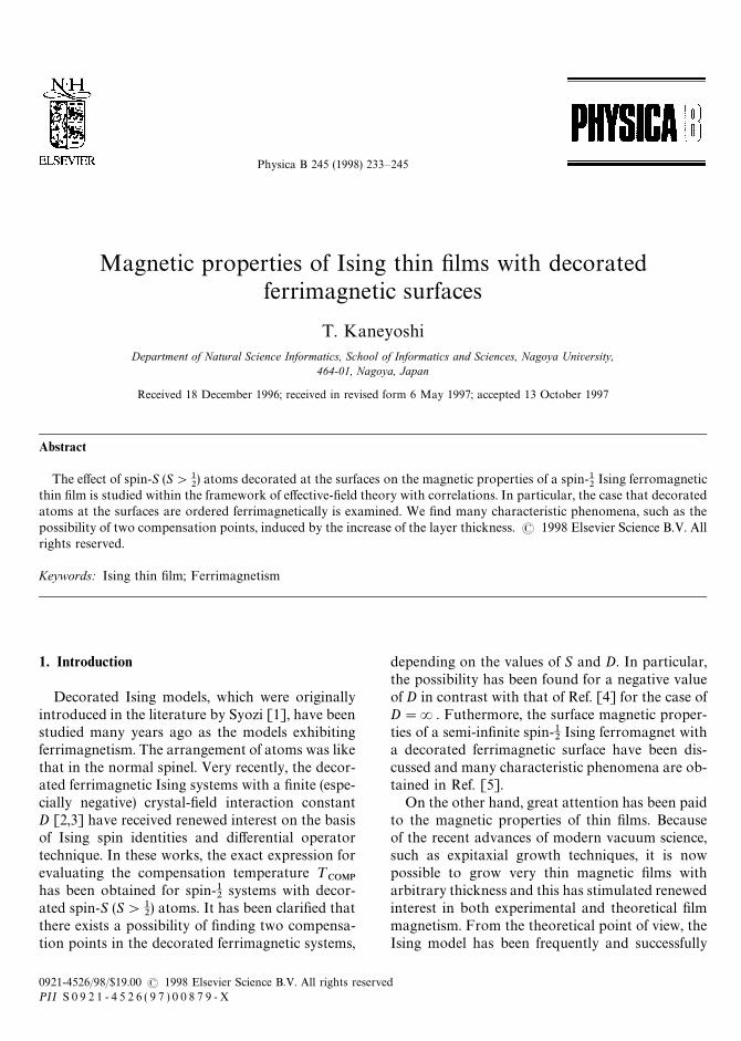
ferrimagnetically on the surfaces. The structure hassimple cubic symmetry composed of ¸ atomiclayers in the z-direction. The two-dimensionalcross-section is schematically depicted in Fig. 1. Inparticular, systems A and B in the figure are alsodiscussed in this work as special cases of systemsC and D, in order to clarify the effects of thedecorated ferrimagnetic surfaces on the magneticproperties. The system, namely system B, C or D, isdescribed by the Hamiltonian
H"!Js+(ij)
kzis
kzjs#J@
s+(im)
kzisSzms!D+
m
(Szms
)2
!J +(ll)
+(ij)
kzil kz
jl , (1)
where l denotes each layer (l"1, 2,2,L) andl"s for the two (0 0 1) surfaces (l"1 and ¸).kzil takes kz
il"$12
on the spin-12
atom (white circle)in each layer and Sz
ml (l"s) is the spin operator ofthe decorated spin-S atom (black circle) on the twosurfaces. D is the crystal-field interaction constantof spin-S atom on the surfaces. The J
S, J
S’ and J are
the nearest-neighbor exchange interaction con-stants between the corresponding spin pairs andthey are assumed to be positive. In particular, theHamiltonian for system A can be represented byputting J"0 into Eq. (1).
The total magnetization M of the system com-posed of ¸ layers is
M
N"2M
s#
L~1+l/2
pl (2)
with
Ms"p
s#2m
s, (3)
where N is the number of spin-12
atoms on eachlayer and the total magnetization on the (0 0 1)surfaces is given by NM
s. The magnetizations
pl(l"s, 2,2, ¸!1) and msare then defined by
pl"SkzilT and m
s"SSz
msT, (4)
where S2T represents the thermal average.
234 T. Kaneyoshi / Physica B 245 (1998) 233—245
Fig. 1. Parts of two-dimensional cross-sections simple cubic thin films with decorated surfaces, namely systems C and D, where thewhite and black circles represent respectively spin-1
2atoms and spin-S (S'1
2) atoms. Systems A and B are special cases of systems C and
D. System A is composed of one layer (square lattice) with the two kinds of magnetic atoms. System B consists of the two decoratedlayers deposited on a nonmagnetic substrate.
The main aim of this work is to clarify the roleof the decorated ferrimagnetic surfaces on the totalmagnetization M in thin films with thickness ¸. Letus at first study the surface magnetization M
S. By
the use of Ising spin identities and the differentialoperator technique [16], the magnetization m
Scan
be expressed exactly in the form [2,3,5]
ms"SSz
msT"Sexp(akz
is) exp(akz
js)TF
s(x)D
x/0
"!2psF
s(J@
s), (5)
where a"J@s+, +"/x is the differential oper-
ator, and the sites i and j are the nearest-neighborsof the site m on the (0 0 1) surface. The functionFs(x) depends on the values of S and D, which is
given in Appendix A. Accordingly, the Mson the
surface is exactly given by
Ms"p
s[1!4F
s(J@
s)]. (6)
Thus, the problem is how to calculate the magneti-zation pl(l"s, 2,2, ¸!1) on each layer.
Now, the magnetization pl is defined by
pl"SkzilT"
TrMkzil exp(!bH)N
TrMexp(!bH)N(7)
with b"1/kB¹. In order to calculate Eq. (7), we
introduce the effective interaction Js%&&
on the sur-face as follows [1—5,15];
+ exp [!bJ@s(kz
is#kz
js) Sz
ms#bD (Sz
ms)2]
"Asexp(b Js
%&&kzis
kzjs), (8)
where Asand Js
%&&depend on the values of S and D,
and they are given in Appendix B. As discussed inRefs. [3,15], using the differential operator tech-nique and the fact that the Hamiltonian in Eq. (7)can be then replaced by the effective HamiltonianH
%&&, namely
H%&&"!(J
S#Js
%&&) +(ij)
kziS
kzjS!J+
(ll)+(ij)
kzil kz
jl,
(9)
T. Kaneyoshi / Physica B 245 (1998) 233—245 235
the magnetization pl in the thin film with thickness¸ can be given, within the framework of EFT, in theforms
ps"[cosh(b
s/2)#2p
ssinh(b
s/2)]4
[cosh(b/2)#2p2
sinh(b/2)] f (x)Dx/0
for the two surfaces (10)
pl"[cosh(b/2)#2pl sinh(b/2)]4[cosh(b/2)
#2pl`1sinh(b/2)][cosh(b/2)
#2pl~1sinh(b/2)] f (x)D
x/0
for 2)l)¸!1, (11)
with p1"p
L"p
s,
ps"[cosh(b
s/2)#2p
ssinh(b
s/2)]4 f (x)D
x/0, (12)
for system A in Fig. 1,
ps"[cosh(b
s/2)#2p
ssinh(b
s/2)]4
][cosh(b/2)#2pssinh(b/2)] f (x)D
x/0, (13)
for system B in Fig. 1, where bs"
(Js#Js
%&&)+, b"J+ and the function f (x) is given
by
f (x)"1
2tanh A
bx
2 B . (14)
3. Ultrathin films
Before discussing the magnetic properties ofa thin film with thickness ¸, let us, in this section,study the magnetic properties of the special systemsA and B (or ultrathin films) in Fig. 1, since they willplay important roles for the investigation of a thinfilm with thickness ¸. The magnetizations of thesesystems are respectively given by Eqs. (6) and (12)for system A and Eqs. (6) and (13) for system B,where the spins kz
isand Sz
msin the two systems are
ordered ferrimagnetically. In particular, Eq. (6) in-dicates an important fact: There may exist a com-pensation point at which the magnetization M
sre-
duces to zero even when the temperature is belowthe transition temperature¹
#of a system. If it exists
in the temperature dependence of Ms, the compen-
sation temperature ¹sCOMP
can be exactly deter-
mined from [2]
1"4Fs(J@
s) for ¹s
COMP(¹
#. (15)
Within EFT, the transition temperatures of thetwo systems can be determined from the standardmethod (the linearization of p
s) and they are ob-
tained from the following relations:
1"8 sinh(bs/2) cosh3(b
s/2) f (x)D
x/0(16)
for system A in Fig. 1 and
1"8 sinh(bs/2) cosh3(b
s/2) cosh(b/2) f (x)D
x/0
#2 sinh(b/2)cosh4(b/2) f (x)Dx/0
(17)
for system B in Fig. 1.Eqs. (16) and (17) as well as Eqs. (10)—(13) can be
easily calculated by the use of the mathematicalrelation exp (a+)/(x)"/(x#a).
At this place, let us introduce the parameters a,c and d defined by
a"Js/J, c"J@
s/J and d"D/J (18)
for the numerical calculations. In Fig. 2, the vari-ations of Eq. (15) with d are given by selecting thetwo values of S, namely S"1 and S"3
2, and
changing the value of c. The solid lines representthe results of Eq. (15). Some differences can be seenfrom them, depending on whether S is an integer(S"1) or a half-integer (S"3
2).
In Fig. 2A, the solid lines reduce to zero at a criti-cal negative value d
#(d
#"!c). It comes from the
fact that spin Szms
on the decorated atoms maychange from the Sz
ms"$1 state to Sz
ms"0 state at
¹"0 K, when the value of d is d#"!c. In par-
ticular, each solid curve exhibits the possibility oftwo solutions in the region of d below the criticalvalue d
#(or the reentrant-type phenomenon), such
as !1.12(d(!0.6 for the curve labeledc"0.6. If the two solutions of Eq. (15) in the reen-trant region of d are lower than the corresponding¹
#, it implies that two compensation points may be
observed in the ultrathin ferrimagnetic film. On theother hand, the solutions of Eq. (15) for S"3
2are
plotted in Fig. 2B, changing the value of c. In con-trast to Fig. 2A, the particular value of d does notexist in Fig. 2B at which the solution of Eq. (15)reduces to zero. The reason is as follows. At the
236 T. Kaneyoshi / Physica B 245 (1998) 233—245
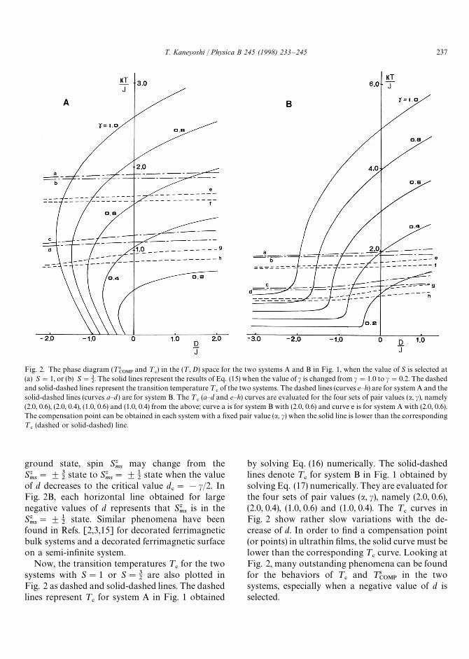
Fig. 2. The phase diagram (¹sCOMP
and ¹#) in the (¹, D) space for the two systems A and B in Fig. 1, when the value of S is selected at
(a) S"1, or (b) S"32. The solid lines represent the results of Eq. (15) when the value of c is changed from c"1.0 to c"0.2. The dashed
and solid-dashed lines represent the transition temperature ¹#of the two systems. The dashed lines (curves e—h) are for system A and the
solid-dashed lines (curves a—d) are for system B. The ¹#(a—d and e—h) curves are evaluated for the four sets of pair values (a, c), namely
(2.0, 0.6), (2.0, 0.4), (1.0, 0.6) and (1.0, 0.4) from the above; curve a is for system B with (2.0, 0.6) and curve e is for system A with (2.0, 0.6).The compensation point can be obtained in each system with a fixed pair value (a, c) when the solid line is lower than the corresponding¹
#(dashed or solid-dashed) line.
ground state, spin Szms
may change from theSzms"$3
2state to Sz
ms"$1
2state when the value
of d decreases to the critical value d#"!c/2. In
Fig. 2B, each horizontal line obtained for largenegative values of d represents that Sz
msis in the
Szms"$1
2state. Similar phenomena have been
found in Refs. [2,3,15] for decorated ferrimagneticbulk systems and a decorated ferrimagnetic surfaceon a semi-infinite system.
Now, the transition temperatures ¹#for the two
systems with S"1 or S"32
are also plotted inFig. 2 as dashed and solid-dashed lines. The dashedlines represent ¹
#for system A in Fig. 1 obtained
by solving Eq. (16) numerically. The solid-dashedlines denote ¹
#for system B in Fig. 1 obtained by
solving Eq. (17) numerically. They are evaluated forthe four sets of pair values (a, c), namely (2.0, 0.6),(2.0, 0.4), (1.0, 0.6) and (1.0, 0.4). The ¹
#curves in
Fig. 2 show rather slow variations with the de-crease of d. In order to find a compensation point(or points) in ultrathin films, the solid curve must belower than the corresponding ¹
#curve. Looking at
Fig. 2, many outstanding phenomena can be foundfor the behaviors of ¹
#and ¹s
COMPin the two
systems, especially when a negative value of d isselected.
T. Kaneyoshi / Physica B 245 (1998) 233—245 237
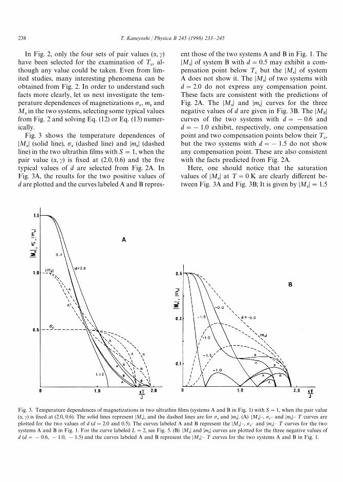
Fig. 3. Temperature dependences of magnetizations in two ultrathin films (systems A and B in Fig. 1) with S"1, when the pair value(a, c) is fixed at (2.0, 0.6). The solid lines represent DM
sD, and the dashed lines are for p
sand Dm
sD. (A) DM
sD—, p
s— and Dm
sD— ¹ curves are
plotted for the two values of d (d"2.0 and 0.5). The curves labeled A and B represent the DMsD—, p
s— and Dm
sD— ¹ curves for the two
systems A and B in Fig. 1. For the curve labeled ¸"2, see Fig. 5. (B) DMsD and Dm
sD curves are plotted for the three negative values of
d (d"!0.6, !1.0, !1.5) and the curves labeled A and B represent the DMsD— ¹ curves for the two systems A and B in Fig. 1.
In Fig. 2, only the four sets of pair values (a, c)have been selected for the examination of ¹
#, al-
though any value could be taken. Even from lim-ited studies, many interesting phenomena can beobtained from Fig. 2. In order to understand suchfacts more clearly, let us next investigate the tem-perature dependences of magnetizations p
s, m
sand
Msin the two systems, selecting some typical values
from Fig. 2 and solving Eq. (12) or Eq. (13) numer-ically.
Fig. 3 shows the temperature dependences ofDM
sD (solid line), p
s(dashed line) and Dm
sD (dashed
line) in the two ultrathin films with S"1, when thepair value (a, c) is fixed at (2.0, 0.6) and the fivetypical values of d are selected from Fig. 2A. InFig. 3A, the results for the two positive values ofd are plotted and the curves labeled A and B repres-
ent those of the two systems A and B in Fig. 1. TheDM
sD of system B with d"0.5 may exhibit a com-
pensation point below ¹#
but the DMsD of system
A does not show it. The DMsD of two systems with
d"2.0 do not express any compensation point.These facts are consistent with the predictions ofFig. 2A. The DM
sD and Dm
sD curves for the three
negative values of d are given in Fig. 3B. The DMSD
curves of the two systems with d"!0.6 andd"!1.0 exhibit, respectively, one compensationpoint and two compensation points below their ¹
#,
but the two systems with d"!1.5 do not showany compensation point. These are also consistentwith the facts predicted from Fig. 2A.
Here, one should notice that the saturationvalues of DM
sD at ¹"0 K are clearly different be-
tween Fig. 3A and Fig. 3B; It is given by DMsD"1.5
238 T. Kaneyoshi / Physica B 245 (1998) 233—245
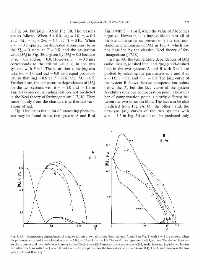
Fig. 4. (A) Temperature dependences of magnetizations in two ultrathin films (systems A and B in Fig. 1) with S"1 are plotted, whenthe parameters a, c and d are selected as a"!1.0, c"0.6 and d"!1.0. The solid lines represent the DM
sD curves. The dashed lines are
for the pscurves and the solid-dashed curves for the 2 Dm
sD curves. (B) Temperature dependences of DM
sD (solid line) and Dm
sD (dashed line) in
two ultrathin films with S"32, a"1.0 and d"!1.0 are plotted for the two values of c (c"0.6 and 0.4). The A and B express the two
systems A and B in Fig. 1.
in Fig. 3A, but DMsD"0.5 in Fig. 3B. The reasons
are as follows. When d'0.0, DmsD"1.0, p
s"0.5
and DMsD"Dp
s#2m
sD"1.5 at ¹"0 K. When
d(!0.6, spin Szms
on decorated atoms must be inthe Sz
ms"0 state at ¹"0 K and the saturation
value DMsD in Fig. 3B is given by DM
sD"0.5 because
of ps"0.5 and m
s"0.0. However, d"!0.6 just
corresponds to the critical value d#
in the twosystems with S"1. The saturation value Dm
sD can
take DmsD"1.0 and Dm
sD"0.0 with equal probabil-
ity, so that DmsD"0.5 at ¹"0 K and DM
sD"0.5.
Furthermore, the temperature dependences of DMsD
for the two systems with d"!1.0 and !1.5 inFig. 3B express outstanding features not predictedin the Neel theory of ferrimagnetism [17,18]. Theycame mainly from the characteristic thermal vari-ations of Dm
sD.
Fig. 3 indicates that a lot of interesting phenom-ena may be found in the two systems A and B of
Fig. 1 with S"1 or 32, when the value of d becomes
negative. However, it is impossible to plot all ofthem and hence let us present only the two out-standing phenomena of DM
sD in Fig. 4, which are
not classified by the classical Neel theory of fer-rimagnetism [17,18].
In Fig. 4A, the temperature dependences of DMsD
(solid line), ps(dashed line) and 2Dm
sD (solid-dashed
line) in the two systems A and B with S"1 areplotted by selecting the parameters p, c and d asa"1.0, c"0.6 and d"!1.0. The DM
sD curve of
the system B shows the two compensation pointsbelow the ¹
#but the DM
sD curve of the system
A exhibits only one compensation point. The num-ber of compensation point is clearly different be-tween the two ultrathin films. The fact can be alsopredicted from Fig. 2A. On the other hand, thenew-type DM
sD curves of the two systems with
d"!1.5 in Fig. 3B could not be predicted only
T. Kaneyoshi / Physica B 245 (1998) 233—245 239
from the phase diagrams of Fig. 2. One of suchphenomena is depicted in Fig. 4B for the two sys-tems with S"3
2, a"1.0 and d"!0.5, when the
two values of c are selected as c"0.6 and c"0.4.Even for the small variation of c the temperaturedependences of DM
sD in the two systems with S"3
2can be changed dramatically, namely from the P-type to the new N-type behavior [17,18]. The ori-gin comes from the different behaviors in the ther-mal variations of Dm
sD (dashed lines). In particular,
the saturation values of msfor the two systems are
given by ms"!0.5, since d"!0.5 is smaller
than the critical value d#"!c/2 at which the
Sms
z may change from the Szms"3
2state to Sz
ms"1
2state.
4. Ising thin films with decorated ferrimagneticsurfaces
In Section 3, we have examined the phase dia-grams and magnetization curves of two ultrathinfilms, namely systems A and B in Fig. 1, and manycharacteristic behaviors have been obtained inthem. As depicted in Fig. 1, such systems are specialcases of the systems C and D. Let us here study themagnetic properties of Ising ferromagnetic thinfilms with the surface ordered ferrimagnetically.
In order to obtain the transition temperature¹
#of a L-layer thin film, it is necessary to solve the
coupled Eqs. (10) and (11). For this purpose, weexpand the right-hand side of these equations andconsider only terms linear inpl (l"s, 2,2, ¸!1, s). From this procedure, wecan obtain the following matrix equation
R Aps
p2F
pL~1ps
B"0 (19)
where the form of matrix R depends on the thick-ness ¸ of the film. The transition temperature of thesystem can be determined from the condition
DRD"0. (20)
From the many formal solutions of Eq. (20), wechoose the one corresponding to the highest pos-sible transition temperature ¹
#, as discussed in
Refs. [6—10].Now, the coupled Eqs. (10) and (11) have the
forms equivalent to those derived for spin-12
Isingthin films [6—11], except that the surface exchangeinteraction J
sis here replaced by J
s#Js
%&&. Further-
more, the derivation of DRD and how to evaluate the¹
#from Eq. (20) have been discussed in detail with-
in the framework of EFT [6—11]. However, most ofthe theoretical studies of spin-1
2Ising thin films have
been directed mainly to get the phase diagrams andthe magnetization profiles. How the temperaturedependences of the total magnetization (or M de-fined by Eq. (2)) are changed with the increase ofthickness ¸ has not been clarified so much [11].
Experimentally, when the thin films are fab-ricated by modern high-vacuum techniques, theanisotropy d at the surfaces often becomes perpen-dicular to the surface planes, namely d'0. Accord-ingly, let us at first study the effects of the surfaceswith a positive value of d on the temperature de-pendences of the total magnetization M, increasingthe layer thickness ¸ from ¸"2 to 12. Such typicalphenomena are depicted in Fig. 5 for the systemswith S"1, a"1.0, c"0.6 and d"0.5 by solvingthe coupled Eqs. (10) and (11) numerically. Thecomplete behavior of M curve labeled ¸"2 isgiven in Fig. 2A. For thin films with 2(¸(8,a compensation point is found in the M curves andthe compensation temperature decreases with theincrease of ¸. For the system with ¸"8, the satu-ration value of M is given by M"0, while it takesa finite value for the system with ¸'8, as shownfor ¸"12. These characteristic features are due tothe existence of decorated ferrimagnetic surfaces.
In general, the surface magnetization mson the
surfaces decorated with spin-S atoms is given bym
s"!S at ¹"0 K, when the value of d is larger
than the critical value d#. Accordingly, the satura-
tion value of Msis M
s"(1!4S)/2. Then, the satu-
ration magnetization of Eq. (2) becomes
M
N"
¸
2!4S at ¹"0 K, (21)
from which the condition M"0 is satisfied at¸"8S. In Fig. 5, S"1 and hence the saturation
240 T. Kaneyoshi / Physica B 245 (1998) 233—245
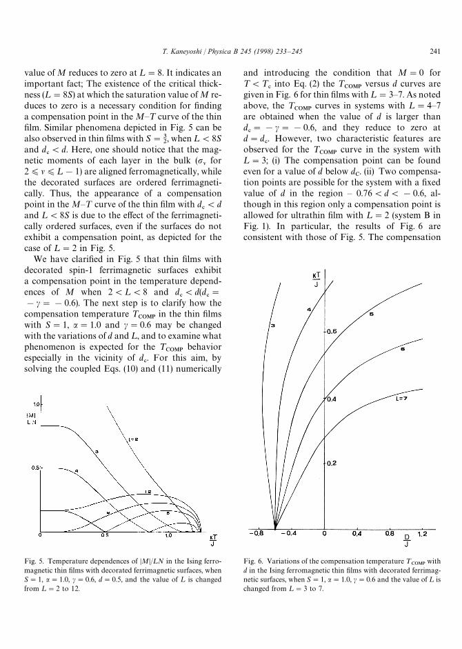
Fig. 5. Temperature dependences of DMD/¸N in the Ising ferro-magnetic thin films with decorated ferrimagnetic surfaces, whenS"1, a"1.0, c"0.6, d"0.5, and the value of ¸ is changedfrom ¸"2 to 12.
Fig. 6. Variations of the compensation temperature ¹COMP
withd in the Ising ferromagnetic thin films with decorated ferrimag-netic surfaces, when S"1, a"1.0, c"0.6 and the value of ¸ ischanged from ¸"3 to 7.
value of M reduces to zero at ¸"8. It indicates animportant fact; The existence of the critical thick-ness (¸"8S) at which the saturation value of M re-duces to zero is a necessary condition for findinga compensation point in the M—¹ curve of the thinfilm. Similar phenomena depicted in Fig. 5 can bealso observed in thin films with S"3
2, when ¸(8S
and d#(d. Here, one should notice that the mag-
netic moments of each layer in the bulk (pl for2)l)¸!1) are aligned ferromagnetically, whilethe decorated surfaces are ordered ferrimagneti-cally. Thus, the appearance of a compensationpoint in the M—¹ curve of the thin film with d
#(d
and ¸(8S is due to the effect of the ferrimagneti-cally ordered surfaces, even if the surfaces do notexhibit a compensation point, as depicted for thecase of ¸"2 in Fig. 5.
We have clarified in Fig. 5 that thin films withdecorated spin-1 ferrimagnetic surfaces exhibita compensation point in the temperature depend-ences of M when 2(¸(8 and d
#(d(d
#"
!c"!0.6). The next step is to clarify how thecompensation temperature ¹
COMPin the thin films
with S"1, a"1.0 and c"0.6 may be changedwith the variations of d and ¸, and to examine whatphenomenon is expected for the ¹
COMPbehavior
especially in the vicinity of d#. For this aim, by
solving the coupled Eqs. (10) and (11) numerically
and introducing the condition that M"0 for¹(¹
#into Eq. (2) the ¹
COMPversus d curves are
given in Fig. 6 for thin films with ¸"3—7. As notedabove, the ¹
COMPcurves in systems with ¸"4—7
are obtained when the value of d is larger thand#"!c"!0.6, and they reduce to zero at
d"d#. However, two characteristic features are
observed for the ¹COMP
curve in the system with¸"3; (i) The compensation point can be foundeven for a value of d below d
C. (ii) Two compensa-
tion points are possible for the system with a fixedvalue of d in the region — 0.76(d(!0.6, al-though in this region only a compensation point isallowed for ultrathin film with ¸"2 (system B inFig. 1). In particular, the results of Fig. 6 areconsistent with those of Fig. 5. The compensation
T. Kaneyoshi / Physica B 245 (1998) 233—245 241
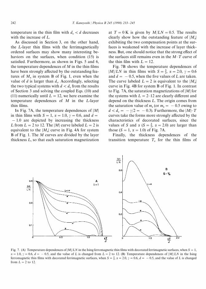
Fig. 7. (A) Temperature dependences of DMD/¸N in the Ising ferromagnetic thin films with decorated ferrimagnetic surfaces, when S"1,a"1.0, c"0.6, d"!0.5, and the value of ¸ is changed from ¸"2 to 12. (B) Temperature dependences of DMD/¸N in the Isingferromagnetic thin films with decorated ferrimagnetic surfaces, when S"3
2, a"2.0, c"0.6, d"!0.5, and the value of ¸ is changed
from ¸"2 to 12.
temperature in the thin film with d#(d decreases
with the increase of ¸.As discussed in Section 3, on the other hand,
the ¸-layer thin films with the ferrimagneticallyordered surfaces may show many interesting be-haviors on the surfaces, when condition (15) issatisfied. Furthermore, as shown in Figs. 5 and 6,the temperature dependences of M in the thin filmshave been strongly affected by the outstanding fea-tures of M
sin system B of Fig. 1, even when the
value of d is larger than d#. Accordingly, selecting
the two typical systems with d(d#from the results
of Section 3 and solving the coupled Eqs. (10) and(11) numerically until ¸"12, we here examine thetemperature dependences of M in the ¸-layerthin films.
In Fig. 7A, the temperature dependences of DMDin thin films with S"1, a"1.0, c"0.6, and d"!1.0 are depicted by increasing the thickness¸ from ¸"2 to 12. The DMD curve labeled ¸"2 isequivalent to the DM
sD curve in Fig. 4A for system
B of Fig. 1. The M curves are divided by the layerthickness ¸, so that each saturation magnetization
at ¹"0 K is given by M/¸N"0.5. The resultsclearly show how the outstanding feature of DM
sD
exhibiting the two compensation points at the sur-faces is weakened with the increase of layer thick-ness. But, one should notice that the strong effect ofthe surfaces still remains even in the M—¹ curve ofthe thin film with ¸"12.
Fig. 7B shows the temperature dependences ofDMD/¸N in thin films with S"3
2, a"2.0, c"0.6
and d"!0.5, when the five values of ¸ are taken.The curve labeled ¸"2 is equivalent to the DM
sD
curve in Fig. 4B for system B of Fig. 1. In contrastto Fig. 7A, the saturation magnetizations of DMD forthe systems with ¸"2—12 are clearly different anddepend on the thickness ¸. The origin comes fromthe saturation value of m
s(or m
s"!0.5 owing to
d(d#"!c/2"!0.3). Furthermore, the DMD—¹
curves take the forms more strongly affected by thecharacteristics of decorated surfaces, since thevalues of S and a (S"3
2, a"2.0) are larger than
those (S"1, a"1.0) of Fig. 7A.Finally, the thickness dependences of the
transition temperature ¹#
for the thin films of
242 T. Kaneyoshi / Physica B 245 (1998) 233—245
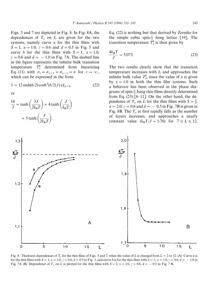
Fig. 8. Thickness dependences of ¹#for the thin films of Figs. 5 and 7, when the value of ¸ is changed from ¸"2 to 12. (A) Curve a is
for the thin films with S"1, a"1.0, c"0.6, d"0.5 in Fig. 5, and curve b is for the thin films with S"1, a"1.0, c"0.6, d"!1.0 inFig. 7A. (B) Dependence of ¹
#on ¸ is plotted for the thin films with S"3
2, a"2.0, c"0.6, d"!0.5 in Fig. 7 B.
Figs. 5 and 7 are depicted in Fig. 8. In Fig. 8A, thedependences of ¹
#on ¸ are given for the two
systems, namely curve a for the thin films withS"1, a"1.0, c"0.6 and d"0.5 in Fig. 5 andcurve b for the thin films with S"1, a"1.0,c"0.6 and d"!1.0 in Fig. 7A. The dashed linein the figure represents the infinite bulk transitiontemperature ¹b
#determined from linearizing
Eq. (11) with pl"pl`1"pl~1
"p for lPR,which can be expressed in the form
1"12 sinh(b/2) cosh5(b/2) f (x)Dx/0
(22)
or
16
3"tanh A
3J
2kB¹B#4 tanh A
J
kB¹B
#5 tanh AJ
2kB¹B .
Eq. (22) is nothing but that derived by Zernike forthe simple cubic spin-1
2Ising lattice [19]. The
transition temperature ¹b#is then given by
4kB¹
J"5.073. (23)
The two results clearly show that the transitiontemperature increases with ¸ and approaches theinfinite bulk value ¹b
#, since the value of a is given
by a"1.0 in both the thin film systems. Sucha behavior has been observed in the phase dia-grams of spin-1
2Ising thin films directly determined
from Eq. (23) [6—11]. On the other hand, the de-pendence of ¹
#on ¸ for the thin films with S"3
2,
a"2.0, c"0.6 and d"!0.5 in Fig. 7B is given inFig. 8B. The ¹
#at first rapidly falls as the number
of layers increases, and approaches a nearlyconstant value (k
B¹/J&1.76) for 7)¸)12.
T. Kaneyoshi / Physica B 245 (1998) 233—245 243
A phenomenon similar to Fig. 8B has been ob-tained for spin-1
2Ising thin films [6—11], when the
surface exchange interaction Js(or a'1) is strong
enough in comparison with the bulk interaction J.In the figure, however, the k
B¹/J"1.760 even for
¸"12 is larger than kB¹/J"1.268. It also indi-
cates that even for the thin films with ¸"12 ¹#is
strongly influenced by the existence of decoratedsurfaces with S"3
2and a"2.
5. Conclusions
In this work, we have discussed the magneticproperties of Ising thin films with decorated ferri-magnetic surfaces depicted in Fig. 1 on the basis ofthe recent formulation (or the EFT) in Refs.[3,5,15]. The fomulation is superior to the standardeffective-field theory with correlations [20]. In fact,when it is applied to the one-dimensional mixed-spin Ising chain, exact results can be obtained forthe magnetic properties [3,15].
In Section 3, we have examined the magneticproperties of two ultrathin films, namely systemsA and B in Fig. 1. As shown in Figs. 2—4, theyexhibit many interesting phenomena, such as thepossibility of two compensation points, althoughthey are qualitatively similar to those reported inRefs. [2,13,14,21,22] for other systems. In particu-lar, one should notice that the compensation tem-peratures ¹s
COMPdetermined from Eq. (15) are
exact, while the transition temperatures ¹#are ap-
proximately evaluated within EFT. The behaviorsof ¹s
COMPare rather different, depending on the
values of S and c as well as whether the system isselected as system A or system B in Fig. 1.
In Section 4, thin films with ferrimagneticallydecorated surfaces, namely system C and D inFig. 1, have been examined by increasing the thick-ness ¸ from ¸"2 to 12. As depicted in Figs. 5—8,the magnetic properties are strongly influenced bythe existence of two surfaces. The total magnet-ization curve of Fig. 7 represent new types ofmagnetization that have not been predicted in theclassical Neel theory, although the magnetizationcurves of Fig. 7 exhibit those (N-, ¸-, P-types) fol-lowing Neel theory [17,18]. The results of Fig. 8express that the transition temperature of the Ising
thin film with thickness ¸ is strongly influenced bythe existence of decorated surfaces. Thus, the re-sults of Sections 3 and 4 indicate that when thevalue of d becomes smaller than a critical valued#
(d#"!c for S"1 and d
#"!c/2 for S"3
2),
a number of outstanding phenomena may be ob-tained in the magnetic properties of the presentsystems. Furthermore, when the thickness ¸ be-comes infinite, the characteristic behaviors of thesemi-infinite spin-1
2Ising ferromagnet with a decor-
ated ferrimagnetic surface in Ref. [5] can be alsoobtained from this formulation.
Finally, we hope that systems similar to thosediscussed in this work may be prepared experi-mentally and outstanding phenomena, such as themulticompensation points, induced by the increaseof thickness, will be possible in future from experi-mental research. We may conclude by saying thatIsing thin films with decorated surfaces are fruitfulsystems from theoretical and the material sciencepoints of view.
Appendix A.
The function Fs(x) introduced in Eq. (5) is defined
by
Fs(x)"
2 sinh(bx)
2 cosh(bx)#exp(!bD), (A.1)
for S"1,
FS(x)"
1
2
3 sinh(3bx/2)#exp(!bD) sinh(bx/2)
cosh(3bx/2)#exp(!bD) cosh(bx/2),
(A.2)
for S"32, and so on Ref. [13].
Appendix B.
The effective interaction Js%&&
and the coefficientA
sdefined in Eq. (8) are, respectively, given by
Js%&&"
2
bln C
2 cosh(bJ@s)#exp(!bD)
2#exp(!bD) D (B.1a)
As"exp(bJs
%&&/4) [2 exp(bD)#1] (B.1)
244 T. Kaneyoshi / Physica B 245 (1998) 233—245
when Szms"$1 and 0,
Js%&&"
2
bln C
cosh(3bJ@s/2)#exp(!2bD)
1#exp(!2bD) D , (B.2a)
AS"2 exp(bJs
%&&/4) [exp(9bD/4)#exp(bD/4)]1@2,
(B.2b)
when Szms"$3
2and $1
2, and so on.
References
[1] I. Syozi, in: C. Domb, M.S. Green (Eds.), Phase Transitionsand Critical Phenomena, vol. 1, Academic Press, NewYork, 1972.
[2] T. Kaneyoshi, J. Phys. Condens. Matter 8 (1996) 4515; andPhysica A 229 (1996) 166.
[3] T. Kaneyoshi, Physica A 237 (1997) 554.[4] M. Hattori, Prog. Theor. Phys. 35 (1966) 600.[5] T. Kaneyoshi, Phys. Rev. B 55 (1997) 12497.[6] T. Balcerzak, J. Mielnicki, G. Wiatrowski, A. Urbaniak-
Kucharczyk, J. Phys. Condens. Matter 2 (1990) 3955;G. Wiatrowski, J. Mielnicki, T. Balcerzak, Phys. Stat. Sol.(B) 164 (1991) 299.
[7] Q. Hong, Phys. Rev. B 41 (1990) 9621.
[8] X.Z. Wang, X.Y. Jiao, J.J. Wang, J. Phys. Condens. Matter4 (1992) 3651; C. Jia, X.Z. Wang, J. Phys. Condens. Matter8 (1996) 5745; S.C. Lii, X.Z. Wang, Phys. Rev. B 51 (1995)6715.
[9] J.W. Tucker, E.F. Sarmento, C. Cressoni, J. Magn. Magn.Mater. 147 (1995) 24.
[10] T. Kaneyoshi, T. Balcerzak, Physica A 197 (1993) 667;T. Balcerzak, T. Kaneyoshi, Physica A 206 (1994) 176.
[11] S.C. Lii, X.Z. Wang, Physica A 232 (1996) 315.[12] H. Wan, A. Tsoukatos, G.C. Hadjipanayis, J. Magn.
Magn. Mater. 125 (1993) 157; G. Srinivasan, B. Uma,Maheshawan Rao, J. Zhao, M. Sachra, Appl. Phys. Lett.59 (1991) 372.
[13] M. Jas\ c\ ur, T. Kaneyoshi, Phys. Rev. B 54 (1996) 9232.[14] M. Jas\ c\ ur, T. Kaneyoshi, Phys. Stat. Sol. (B) 200 (1997)
249.[15] T. Kaneyoshi, Prog. Theor. Phys. 97 (1997) 407.[16] T. Kaneyoshi, Acta Phys. Pol. A 83 (1993) 703.[17] L. Neel, Ann. Phys. 3 (1948) 137.[18] A. Herpin, Theorie du Magnetisme, Presses Universitaires
de France, Saclay, 1968.[19] F. Zernike, Physica 7 (1940) 565.[20] R. Honmura, T. Kaneyoshi, J. Phys. C 12 (1979) 3979.[21] T. Kaneyoshi, M. Jas\ c\ ur, J. Phys. Condens. Matter
5 (1993) 3253.[22] T. Kaneyoshi, J. Phys. Condens. Matter 5 (1993) L501;
Physica B 210 (1995) 178; J. Magn. Magn. Mater. 140—144(1995) 261; Phys. Rev. B 52 (1995) 7304.
T. Kaneyoshi / Physica B 245 (1998) 233—245 245