magelis xbt-g modbus (rtu) driver -...
TRANSCRIPT

3500
7086
Magelis XBT-GModbus (RTU) driver eng

2
Table of Contents
About the Book . . . . . . . . . . . . . . . . . . . . . . . . . . . . . . . . . . . . . . .5
Chapter 1 Modbus (RTU) Driver . . . . . . . . . . . . . . . . . . . . . . . . . . . . . . . . . . 7At a Glance . . . . . . . . . . . . . . . . . . . . . . . . . . . . . . . . . . . . . . . . . . . . . . . . . . . . . . 7System Structure. . . . . . . . . . . . . . . . . . . . . . . . . . . . . . . . . . . . . . . . . . . . . . . . . . 8Cable Diagrams. . . . . . . . . . . . . . . . . . . . . . . . . . . . . . . . . . . . . . . . . . . . . . . . . . . 9Supported Equipment Addresses . . . . . . . . . . . . . . . . . . . . . . . . . . . . . . . . . . . . 11Consecutive Equipment Addresses . . . . . . . . . . . . . . . . . . . . . . . . . . . . . . . . . . 13Environment Setup . . . . . . . . . . . . . . . . . . . . . . . . . . . . . . . . . . . . . . . . . . . . . . . 14I/O Manager Configuration . . . . . . . . . . . . . . . . . . . . . . . . . . . . . . . . . . . . . . . . . 16Driver Configuration . . . . . . . . . . . . . . . . . . . . . . . . . . . . . . . . . . . . . . . . . . . . . . 17Equipment Configuration. . . . . . . . . . . . . . . . . . . . . . . . . . . . . . . . . . . . . . . . . . . 19Equipment Address Configuration. . . . . . . . . . . . . . . . . . . . . . . . . . . . . . . . . . . . 20
Index . . . . . . . . . . . . . . . . . . . . . . . . . . . . . . . . . . . . . . . . . . . . . . 23
3

4
About the Book
At a Glance
Document Scope This documentation presents Modbus (RTU) driver for Magelis XBT-G.
Related Documents
User Comments We welcome your comments about this document. You can reach us by e-mail at [email protected]
Title of Documentation Reference Number
Vijeo-Designer Tutorial VJDUSE00010E
September 2003 5

About the Book
6 September 2003
September 2003
1
Modbus (RTU) DriverAt a Glance
Subject of this chapter
This chapter explains how to connect the target machine with Modbus series equipment. For information about how to use the Vijeo-Designer software, please refer to the Vijeo-Designer Online Help.The types of target machines that are compatible with Vijeo-Designer depends on the version of Vijeo-Designer. For information about the compatibility of target machines, please refer to the Vijeo-Designer Online Help.
What's in this Chapter?
This chapter contains the following topics:
Note: target machines mean Magelis XBT-G products.
Topic Page
System Structure 8
Cable Diagrams 9
Supported Equipment Addresses 11
Consecutive Equipment Addresses 13
Environment Setup 14
I/O Manager Configuration 16
Driver Configuration 17
Equipment Configuration 19
Equipment Address Configuration 20
7
Modbus (RTU) Driver
System Structure
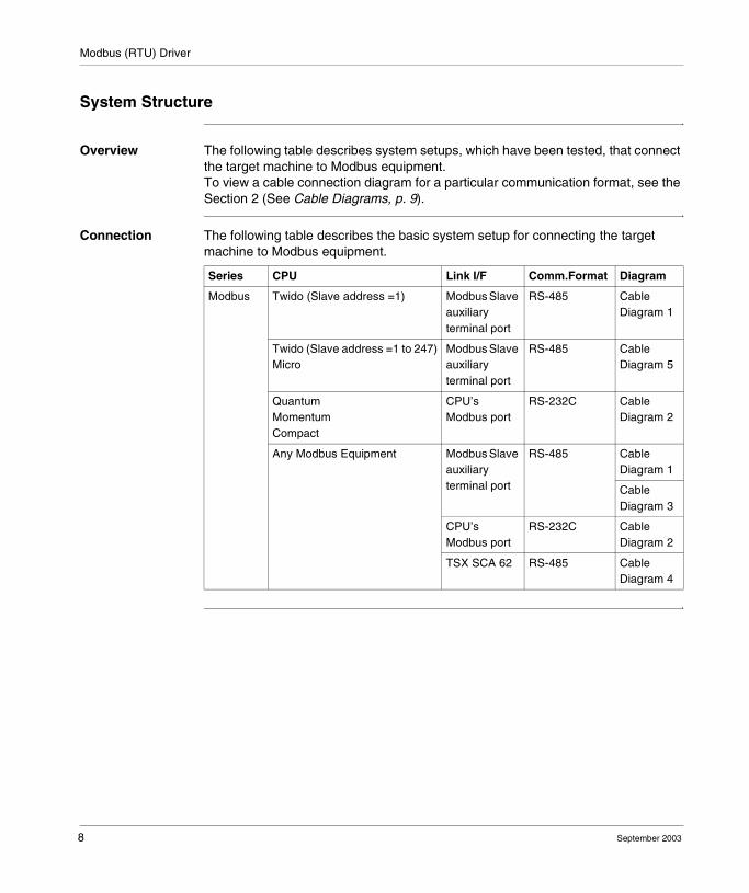
Overview The following table describes system setups, which have been tested, that connect the target machine to Modbus equipment.To view a cable connection diagram for a particular communication format, see the Section 2 (See Cable Diagrams, p. 9).
Connection The following table describes the basic system setup for connecting the target machine to Modbus equipment.
Series CPU Link I/F Comm.Format Diagram
Modbus Twido (Slave address =1) Modbus Slave auxiliary terminal port
RS-485 Cable Diagram 1
Twido (Slave address =1 to 247)Micro
Modbus Slave auxiliary terminal port
RS-485 Cable Diagram 5
QuantumMomentumCompact
CPU’s Modbus port
RS-232C Cable Diagram 2
Any Modbus Equipment Modbus Slave auxiliary terminal port
RS-485 Cable Diagram 1
Cable Diagram 3
CPU’s Modbus port
RS-232C Cable Diagram 2
TSX SCA 62 RS-485 Cable Diagram 4
8 September 2003
Modbus (RTU) Driver
Cable Diagrams
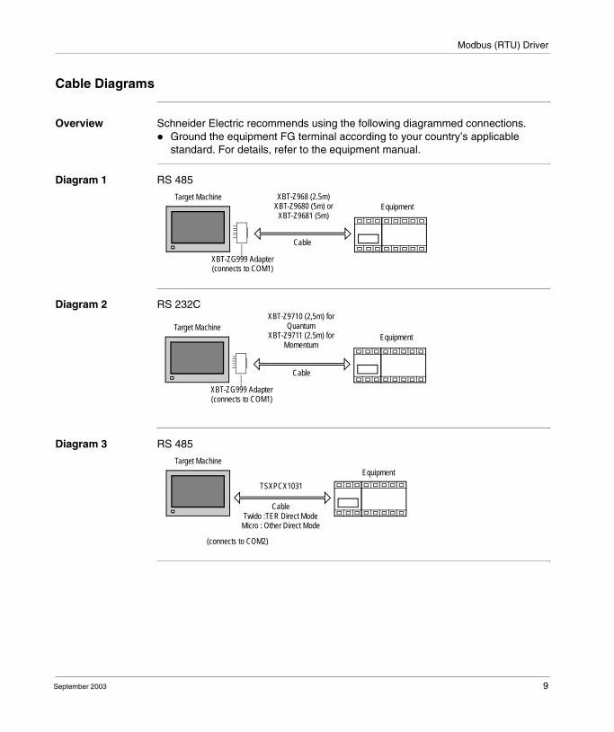
Overview Schneider Electric recommends using the following diagrammed connections.� Ground the equipment FG terminal according to your country’s applicable
standard. For details, refer to the equipment manual.
Diagram 1 RS 485
Diagram 2 RS 232C
Diagram 3 RS 485
Target Machine XBT-Z968 (2.5m)XBT-Z9680 (5m) or
XBT-Z9681 (5m)
Cable
XBT-ZG999 Adapter(connects to COM1)
Equipment
XBT-Z9710 (2,5m) for Quantum
XBT-Z9711 (2.5m) for Momentum
Target Machine
Cable
XBT-ZG999 Adapter(connects to COM1)
Equipment
Target Machine
TSXPCX1031
CableTwido :TER Direct Mode
Micro : Other Direct Mode
(connects to COM2)
Equipment
September 2003 9
Modbus (RTU) Driver
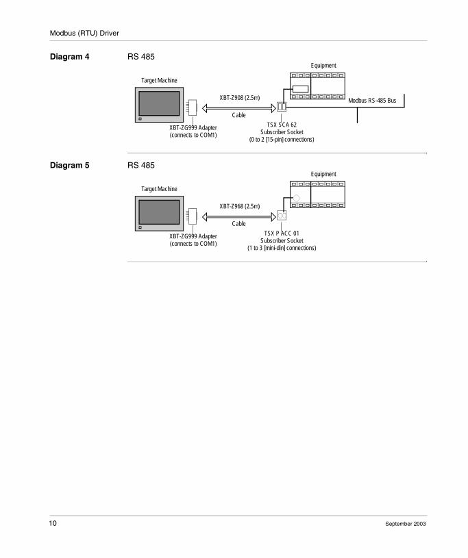
Diagram 4 RS 485
Diagram 5 RS 485
Target Machine
Equipment
XBT-Z908 (2.5m)
Cable
XBT-ZG999 Adapter(connects to COM1)
Modbus RS-485 Bus
TSX SCA 62Subscriber Socket
(0 to 2 [15-pin] connections)
Target Machine
Equipment
XBT-Z968 (2.5m)
Cable
XBT-ZG999 Adapter(connects to COM1)
TSX P ACC 01Subscriber Socket
(1 to 3 [mini-din] connections)
10 September 2003
Modbus (RTU) Driver
Supported Equipment Addresses
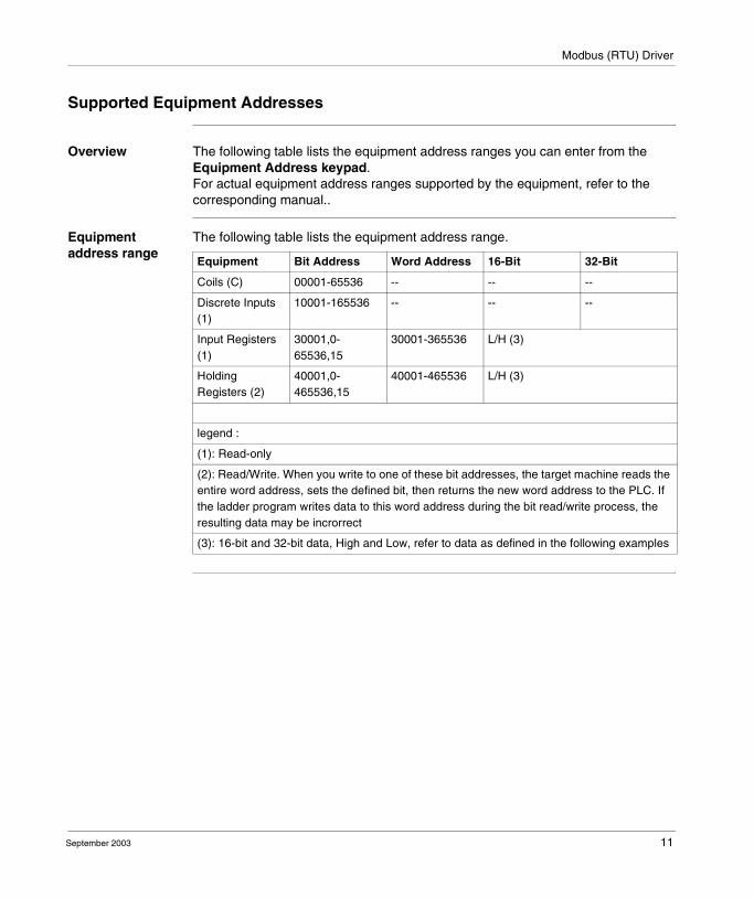
Overview The following table lists the equipment address ranges you can enter from the Equipment Address keypad.For actual equipment address ranges supported by the equipment, refer to the corresponding manual..
Equipment address range
The following table lists the equipment address range.
Equipment Bit Address Word Address 16-Bit 32-Bit
Coils (C) 00001-65536 -- -- --
Discrete Inputs (1)
10001-165536 -- -- --
Input Registers (1)
30001,0-65536,15
30001-365536 L/H (3)
Holding Registers (2)
40001,0-465536,15
40001-465536 L/H (3)
legend :
(1): Read-only
(2): Read/Write. When you write to one of these bit addresses, the target machine reads the entire word address, sets the defined bit, then returns the new word address to the PLC. If the ladder program writes data to this word address during the bit read/write process, the resulting data may be incrorrect
(3): 16-bit and 32-bit data, High and Low, refer to data as defined in the following examples
September 2003 11

Modbus (RTU) Driver
16/32 bit examples
The word (16-bit) is managed as follows:� least significant = byte n� most significant = byte n + 1(Check that the connected equipment uses the same format).The double word and floating point word (32-bit) are managed as follows:� least significant = word n� most significant = word n + 1(Check that the connected equipment uses the same format.)16-bit and 32-bit data, High and Low example.
Note: In case of different format between target machine and the equipment, use intermediate variable (which will be used in target machine) for which most significant byte/word and most significant byte/word are inverted.
16 bitByte
L (Low)
H (High)
0
1
7
15
0
8
. . .
. . .
32 bitWord
L (Low)
H (High)
0
1
15
31
0
16
. . .
. . .
12 September 2003
Modbus (RTU) Driver
Consecutive Equipment Addresses
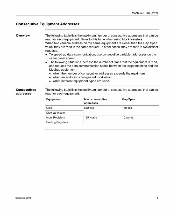
Overview The following table lists the maximum number of consecutive addresses that can be read for each equipment. Refer to this table when using block transfers.When two variable address on the same equipment are closer than the Gap Span value, they are read in the same request. In other cases, they are read in two distinct requests.� To speed up data communication, use consecutive variable addresses on the
same panel screen.� The following situations increase the number of times that the equipment is read,
and reduces the data communication speed between the target machine and the Modbus equipment:� when the number of consecutive addresses exceeds the maximum� when an address is designated for division� when different equipment types are used.
Consecutives addresses
The following table lists the maximum number of consecutive addresses that can be read for each equipment.
Equipment Max. consecutive addresses
Gap Span
Coils 512 bits 160 bits
Discrete Inputs
Input Registers 125 words 10 words
Holding Registers
September 2003 13
Modbus (RTU) Driver
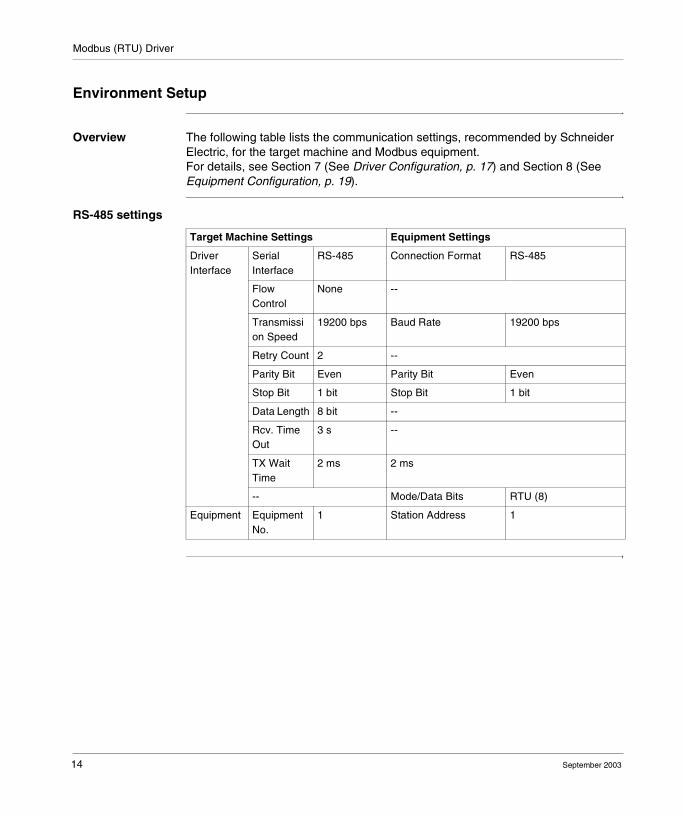
Environment Setup
Overview The following table lists the communication settings, recommended by Schneider Electric, for the target machine and Modbus equipment.For details, see Section 7 (See Driver Configuration, p. 17) and Section 8 (See Equipment Configuration, p. 19).
RS-485 settings
Target Machine Settings Equipment Settings
Driver Interface
Serial Interface
RS-485 Connection Format RS-485
Flow Control
None --
Transmission Speed
19200 bps Baud Rate 19200 bps
Retry Count 2 --
Parity Bit Even Parity Bit Even
Stop Bit 1 bit Stop Bit 1 bit
Data Length 8 bit --
Rcv. Time Out
3 s --
TX Wait Time
2 ms 2 ms
-- Mode/Data Bits RTU (8)
Equipment Equipment No.
1 Station Address 1
14 September 2003

Modbus (RTU) Driver
RS-232C settings
Target Machine Equipment Settings
Driver interface Serial Interface RS-232C Connection Format
RS-232C
Flow Control DTR(ER)/CTS --
Transmission Speed
19200 bps Baud Rate 19200 bps
Retry Count 2 --
Parity Bit Even Parity Bit Even
Stop Bit 1 bit Stop Bit 1 bit
Data Length 8 bits --
Rcv. Timeout 10 sec --
TX Wait Time 2 msec 2 msec
-- Mode/Data Bits RTU 8
Equipment Equipment No. 1 Station Address 1
September 2003 15

Modbus (RTU) Driver
I/O Manager Configuration
Overview The driver and equipment, which enable communication between the target machine and the equipment, depends on the equipment type.
Screen example Screen example of I/O Manager Configuration.
Note: For information on how to display the New Driver Interface dialog box, or for details about the I/O Manager, see the online help: Communication -> External I/O -> Setup I/O.
New Driver Interface
Manufacturer:
Schneider Electric Industries SAS
Driver:
Modbus(RTU)
Equipment:
Modbus Equipment
OK Cancel
ModiconTCP/IPUni-Telway
16 September 2003
Modbus (RTU) Driver
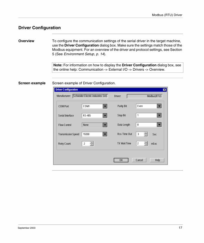
Driver Configuration
Overview To configure the communication settings of the serial driver in the target machine, use the Driver Configuration dialog box. Make sure the settings match those of the Modbus equipment. For an overview of the driver and protocol settings, see Section 5 (See Environment Setup, p. 14).
Screen example Screen example of Driver Configuration.
Note: For information on how to display the Driver Configuration dialog box, see the online help: Communication -> External I/O -> Drivers -> Overview.
Driver Configuration
Manufacturer:
OK Cancel Help
2Retry Count
Schneider Electric industries SAS Driver: Modbus(RTU)
mSec
19200Transmission Speed
NoneFlow Control
RS-485Serial Interface
COM1COM Port
2TX Wait Time
Rcv. Time Out
8Data Length
1Stop Bit
EvenParity Bit
Sec3
September 2003 17
Modbus (RTU) Driver
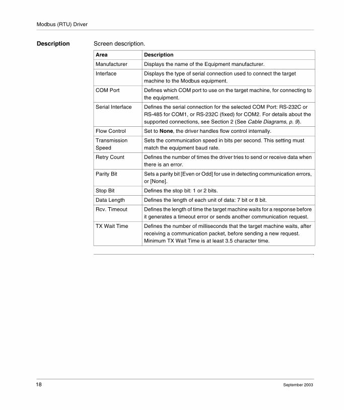
Description Screen description.
Area Description
Manufacturer Displays the name of the Equipment manufacturer.
Interface Displays the type of serial connection used to connect the target machine to the Modbus equipment.
COM Port Defines which COM port to use on the target machine, for connecting to the equipment.
Serial Interface Defines the serial connection for the selected COM Port: RS-232C or RS-485 for COM1, or RS-232C (fixed) for COM2. For details about the supported connections, see Section 2 (See Cable Diagrams, p. 9).
Flow Control Set to None, the driver handles flow control internally.
Transmission Speed
Sets the communication speed in bits per second. This setting must match the equipment baud rate.
Retry Count Defines the number of times the driver tries to send or receive data when there is an error.
Parity Bit Sets a parity bit [Even or Odd] for use in detecting communication errors, or [None].
Stop Bit Defines the stop bit: 1 or 2 bits.
Data Length Defines the length of each unit of data: 7 bit or 8 bit.
Rcv. Timeout Defines the length of time the target machine waits for a response before it generates a timeout error or sends another communication request.
TX Wait Time Defines the number of milliseconds that the target machine waits, after receiving a communication packet, before sending a new request. Minimum TX Wait Time is at least 3.5 character time.
18 September 2003
Modbus (RTU) Driver
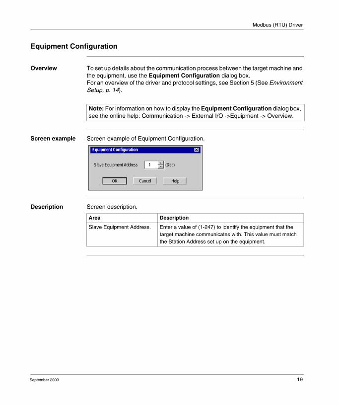
Equipment Configuration
Overview To set up details about the communication process between the target machine and the equipment, use the Equipment Configuration dialog box.For an overview of the driver and protocol settings, see Section 5 (See Environment Setup, p. 14).
Screen example Screen example of Equipment Configuration.
Description Screen description.
Note: For information on how to display the Equipment Configuration dialog box, see the online help: Communication -> External I/O ->Equipment -> Overview.
Equipment Configuration
OK Cancel Help
1 (Dec)Slave Equipment Address
Area Description
Slave Equipment Address. Enter a value of (1-247) to identify the equipment that the target machine communicates with. This value must match the Station Address set up on the equipment.
September 2003 19
Modbus (RTU) Driver
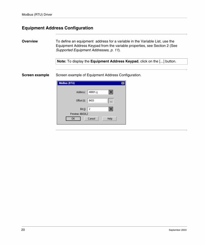
Equipment Address Configuration
Overview To define an equipment address for a variable in the Variable List, use the Equipment Address Keypad from the variable properties, see Section 2 (See Supported Equipment Addresses, p. 11).
Screen example Screen example of Equipment Address Configuration.
Note: To display the Equipment Address Keypad, click on the [...] button.
Modbus (RTU)
OK Cancel Help
40001.i,jAddress:
...8433Offset (i):
2Bit (j)
Preview: 48434,2
20 September 2003
Modbus (RTU) Driver
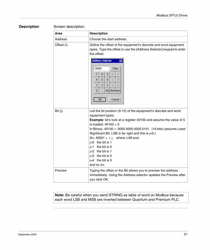
Description Screen description.
Area Description
Address Choose the start address.
Offset (i) Define the offset of the equipment’s discrete and word equipment types. Type the offset or use the [Address Selector] keypad to enter the offset:
Bit (j) List the bit position (0-15) of the equipment’s discrete and word equipment types.Example: let's look at a register 40100 and assume the value of 5 is loaded: 40100 = 5 In Binary, 40100 = 0000 0000 0000 0101 (16 bits) (assume Least Significant Bit, LSB is far right and this is j=0.)So, 40001 + i, j where i=99 and:j=0 the bit is 1j=1 the bit is 0j=2 the bit is 1j=3 the bit is 0j=4 the bit is 0and so on.
Preview Typing the offset or the Bit allows you to preview the address immediately. Using the Address selector updates the Preview after you click OK.
Note: Be careful when you send STRING as table of word on Modbus because each word LSB and MSB are inverted between Quantum and Premium PLC.
Address Selector
OK Cancel
00000
7 8 9 E F
Clear
4 5 6 C D
1 2 3 A B
0 : Del BackSpace
September 2003 21

Modbus (RTU) Driver
22 September 2003