mackie control universal pro/mackie control extender … · mackie control universal pro mackie...
TRANSCRIPT

Quick-Start Guide
Mackie Control Universal Pro Mackie Control Extender Pro
Eight Channel Master Control Surface and Eight Channel Extender for Digital Audio Workstations
5
U
5
10
20
30
40
50
60
10dB
5
U
5
10
20
30
40
50
60
10dB
5
U
5
10
20
30
40
50
60
10dB
5
U
5
10
20
30
40
50
60
10dB
5
U
5
10
20
30
40
50
60
10dB
5
U
5
10
20
30
40
50
60
10dB
5
U
5
10
20
30
40
50
60
10dB
5
U
5
10
20
30
40
50
60
10dB
5
U
5
10
20
30
40
50
60
10dB
BANK
CHANNEL
SOLOCYCLE DROP REPLACE CLICK
SIGNAL SIGNAL SIGNAL SIGNAL SIGNAL SIGNAL SIGNAL SIGNAL
FLIP GLOBALVIEW
+
0
–
+
0
–
+
0
–
+
0
–
+
0
–
+
0
–
+
0
–
+
0
–
DISPLAY
MODIFIERS AUTOMATION UTILITIES
CONTROL
SHIFT OPTION READ/OFF WRITE
TOUCH LATCH
TRIM
CANCEL
SMPTEBEATS
ENTER
SAVE UNDO
/ALT
GLOBAL VIEW
FUNCTION SELECT
NAMEVALUE
MIDITRACKS
INPUTS AUDIOTRACKS
AUDIOINSTRUMENT
AUX BUSSES OUTPUTS USER
F1 F2 F3 F4 F5 F6 F7 F8
87654321
MASTER
FADER BANKS
EQ INSTRUMENT
PLUG-IN
TRACK SEND
PAN/SURROUND
VPOT ASSIGN
GROUP
MARKER NUDGE
REC
REWIND FAST FWD PLAYSTOP RECORD
ASSIGNMENT TICKSSUB DIVISIONBEATSBARS
SMPTE
BEATS
HOURS MINUTES SECONDS FRAMES
RUDE SOLO
REWIND FAST FWD PLAYSTOP RECORD
MACKIE CONTROL UNIVERSAL PRO
REC REC REC REC REC REC REC
SCRUB
ZOOM
87654321
5
U
5
10
20
30
40
50
60
10dB
5
U
5
10
20
30
40
50
60
10dB
5
U
5
10
20
30
40
50
60
10dB
5
U
5
10
20
30
40
50
60
10dB
5
U
5
10
20
30
40
50
60
10dB
5
U
5
10
20
30
40
50
60
10dB
5
U
5
10
20
30
40
50
60
10dB
5
U
5
10
20
30
40
50
60
10dB
+
0
–
+
0
–
+
0
–
+
0
–
+
0
–
+
0
–
+
0
–
+
0
–
MACKIE CONTROL EXTENDER PRO
SIGNAL SIGNAL SIGNAL SIGNAL SIGNAL SIGNAL SIGNAL SIGNAL
REC REC REC REC REC REC REC REC

Part No. SW0454 Rev. A 01/07© 2007 LOUD Technologies Inc. All Rights Reserved.
� Mackie Control Universal Pro
Macki
e C
on
tro
l U
niv
ers
al
Pro
1. Readtheseinstructions.
2. Keeptheseinstructions.
3. Heedallwarnings.
4. Followallinstructions.
5. Donotusethisapparatusnearwater.
6. Cleanonlywithdrycloth.
7. Donotblockanyventilationopenings.Installinaccordancewiththemanufacturer’sinstructions.
8. Donotinstallnearanyheatsourcessuchasradiators,heatregisters,stoves,orotherapparatus(includingamplifiers)thatproduceheat.
9. Donotdefeatthesafetypurposeofthepolarizedorgrounding-typeplug.Apolarizedplughastwobladeswithonewiderthantheother.Agrounding-typeplughastwobladesandathirdgroundingprong.Thewidebladeorthethirdprongareprovidedforyoursafety.Iftheprovidedplugdoesnotfitintoyouroutlet,consultanelectricianforreplacementoftheobsoleteoutlet.
10.Protectthepowercordfrombeingwalkedonorpinchedparticu-larlyatplugs,conveniencereceptacles,andthepointwheretheyexitfromtheapparatus.
11.Onlyuseattachments/accessoriesspecifiedbythemanufacturer.
12.Useonlywithacart,stand,tripod,bracket,ortablespecifiedbythemanufacturer,orsoldwiththeapparatus.Whenacartisused,usecautionwhenmovingthecart/apparatuscombinationtoavoidinjuryfromtip-over.
13.Unplugthisapparatusduringlightningstormsorwhenunusedforlongperiodsoftime.
14.Referallservicingtoqualifiedservicepersonnel.Servicingisrequiredwhentheapparatushasbeendamagedinanyway,suchaspower-supplycordorplugisdamaged,liquidhasbeenspilledorobjectshavefallenintotheapparatus,theapparatushasbeenexposedtorainormoisture,doesnotoperatenormally,orhasbeendropped.
15.Thisapparatusshallnotbeexposedtodrippingorsplashing,andnoobjectfilledwithliquids,suchasvases,shallbeplacedontheapparatus.
16.TheACadapterisusedasthepowerdeviceandshouldbeprotectedfromdamage.
17.Thisapparatushasbeenequippedwitharocker-stylepowerswitch.Thisswitchislocatedontherearpanelandshouldremainreadilyaccessibletotheuser.
18.ThisapparatusdoesnotexceedtheClassA/ClassB(whicheverisapplicable)limitsforradionoiseemissionsfromdigitalappara-tusassetoutintheradiointerferenceregulationsoftheCanadianDepartmentofCommunications.
ATTENTION—Le présent appareil numérique n’émet pas de bruits radioélectriques dépassant las limites applicables aux appareils numériques de class A/de class B (selon le cas) prescrites dans le réglement sur le brouillage radioélectrique édicté par les ministere des communications du Canada.
ThisproducthasbeentestedandcomplieswiththefollowingstandardsanddirectivesassetforthbytheEuropeanUnion:
*EN55022RadiatedandConductedEmissions
*EN55024ElectromagneticImmunity
*EN61000-4-2ElectrostaticDischargeImmunity
*EN61000-4-3RFElectromagneticFieldsImmunity
*EN61000-4-4ElectricalFastTransient/BurstImmunity
*EN60950/IEC950ElectricalSafetyRequirements
CAUTION AVISRISK OF ELECTRIC SHOCK
DO NOT OPENRISQUE DE CHOC ELECTRIQUE
NE PAS OUVRIR
CAUTION: TO REDUCE THE RISK OF ELECTRIC SHOCKDO NOT REMOVE COVER (OR BACK)
NO USER-SERVICEABLE PARTS INSIDEREFER SERVICING TO QUALIFIED PERSONNEL
ATTENTION: POUR EVITER LES RISQUES DE CHOCELECTRIQUE, NE PAS ENLEVER LE COUVERCLE. AUCUN
ENTRETIEN DE PIECES INTERIEURES PAR L'USAGER. CONFIERL'ENTRETIEN AU PERSONNEL QUALIFIE.
AVIS: POUR EVITER LES RISQUES D'INCENDIE OUD'ELECTROCUTION, N'EXPOSEZ PAS CET ARTICLE
A LA PLUIE OU A L'HUMIDITE
The lightning flash with arrowhead symbol within an equilateral triangle is intended to alert the user to the presence of uninsulated"dangerous voltage" within the product's enclosure, that may be of sufficient magnitude to constitute a risk of electric shock to persons.
Le symbole éclair avec point de flèche à l'intérieur d'un triangle équilatéral est utilisé pour alerter l'utilisateur de la présence à l'intérieur du coffret de "voltage dangereux" non isolé d'ampleur suffisante pour constituer un risque d'éléctrocution.
The exclamation point within an equilateral triangle is intended to alert the user of the presence of important operating and maintenance (servicing) instructions in the literature accompanying the appliance.
Le point d'exclamation à l'intérieur d'un triangle équilatéral est employé pour alerter les utilisateurs de la présence d'instructions importantes pour le fonctionnement et l'entretien (service) dans le livret d'instruction accompagnant l'appareil.
Important Safety Instructions
WARNING—Toreducetheriskoffireorelectricshock,donotexposethisappliancetorainormoisture.
FCC Information
NOTE: This equipment has been tested and found to comply with the limits for Class B digital devices, pursuant to Part 15 of the FCC Rules. These limits are designed to provide reasonable protection against harmful interference when the equipment is operated in a commercial installation. This equipment gener-ates, uses, and can radiate radio frequency energy and, if not installed and used in accordance with the instruction manual, may cause harmful interference to radio communications. Operation of this equipment in a residential area is likely to cause harmful interference in which case the user will be required to correct the interference at his own expense.
R
�Quick-Start Guide
Qu
ick-S
tart G
uid
e2. Logic Control (use with Apple Logic [previ-
ously Emagic Logic]).
3. HUI (use with Digidesign Pro Tools, including TDM, LE, and M Powered versions).
When you first turn on Mackie Control Univer-sal Pro, the display prompts you to select a mode of operation:
• Press Ch. 1 V-Pot to select Mackie Control.• Press Ch. 4 V-Pot to select HUI.• Press Ch. 8 V-Pot to select Logic Control.Once you’ve made your selection, Mackie Con-
trol Universal Pro will automatically boot into your selected mode each time you turn it on.
To change the mode of operation:1. Turn off the Mackie Control.
2. Hold down both the Ch. 1 and Ch. 2 SELECT buttons while turning on the Mackie Control.
3. The display once again prompts you to select a mode of operation.
InstallationThere are two methods for connecting your
Mackie Control Universal Pro (MCU Pro) to your computer: USB and MIDI.
Note: The USB method is the preferred method because you have all the MIDI ports on the MCU Pro available. If you use MIDI cables to connect the MCU Pro to your computer (or to an external MIDI interface), the other two MIDI ports (3 and 4) on the MCU Pro are inactive.
Connecting with USB• Connect the Mackie Control Universal Pro to
your computer with a USB cable (see “Hook-up 1: USB” on page 4). The USB connection works with both Macintosh and PC platforms and is “plug and play” (no driver installation required!).
Connecting with MIDI• Connect the Mackie Control Universal Pro to
your USB MIDI interface via two MIDI cables (IN and OUT). Use the MIDI 2 (MAIN) MIDI connections on the MCU Pro.
• Connect your MIDI interface to your computer with a USB cable (see “Hookup 2: MIDI” on page 4).
For both methods:• Connect one end of the external power supply
to the MCU Pro, and the other end to an AC power source between 90 VAC and 264 VAC (50–60 Hz).
• Turn on the MCU Pro POWER switch.
• Launch your software program of choice.
• Select your software’s console or surface man-ager set up window.
IntroductionThank you for choosing Mackie for your Digital
Audio Workstation (DAW) control solution. Mackie Control Universal Pro (MCU Pro) and Mackie Con-trol Extender Pro (MCE Pro) provide the familiar feel of analog-style mixing to your DAW environ-ment. But they also deliver the most complete feature set and software compatibility of any control surface available today, including USB connectivity.
The labels for the buttons and controls are spe-cific to Apple Logic Pro. Custom lexan overlays are available for other supported DAWs. Some of these are included with your MCU Pro and others you can order from our website (see the list below for supported DAWs and overlays as of this printing).
These overlays fit over the right-hand side of the control surface and correctly label the buttons for the functionality supported by the DAW you are using. Visit our website (www.mackie.com) to see a list of all the currently supported DAWs, and to or-der an overlay for your particular DAW application.
Your Mackie Control Universal Pro includes a DVD-ROM that contains Tracktion, our easy-to-use Music Production Software for PC or Mac, the perfect companion software for your new Mackie Control Universal Pro. Check our website (www.mackie.com) periodically for Tracktion updates as they become available.
Overlays Included Overlays Available
Pro Tools (HUI) Adobe Audition
Steinberg (Cubase/Nuendo
Propellerhead Reason
MOTU Digital Performer
Ableton Live
Mackie Tracktion Sony Vegas
Cakewalk SONAR Soundscape (Mackie Control)
RML Labs Saw Studio
Software User’s GuidesVisit our website to obtain the latest manuals
and information for all the currently supported DAW applications (www.mackie.com/products/mcu/mcu_support.html).
Changing ModesMackie Control Universal Pro has three differ-
ent modes of operation:1. Mackie Control (use with Mackie Tracktion,
Ableton Live, Cakewalk SONAR, Magix Sam-plitude and Sequoia, MOTU Digital Performer, Propellerhead Reason, RML Labs Saw Studio, Steinberg Nuendo and Cubase SX, and Adobe Audition [previously Syntrillium Cool Edit Pro]).

� Mackie Control Universal Pro
Macki
e C
on
tro
l U
niv
ers
al
Pro
• Select the Mackie Control in the MIDI device setup section of your DAW application.
• Once the Mackie Control is selected within your software’s setup preferences, the unit(s) will be recognized automatically.
• Mackie Control Universal Pro/Mackie Control Extender Pro units can function as a single large console — a “Control Surface Group.”
• Go to the MCU Support section on our website (www.mackie.com/products/mcu/mcu_support) for details on using the MCU Pro with your particular application.
To connect one or more Mackie Control Extender Pros:1. If you are using the USB method to connect the
MCU Pro to your computer, then the MCU Pro has three sets of MIDI IN/OUT connectors for connecting additional MCE Pro units. Always connect MIDI OUT from one unit to MIDI IN on the next unit (and MIDI IN to MIDI OUT).
2. If you are using the MIDI method to connect the MCU Pro to your computer, then you need to connect the MCE Pro to the external USB MIDI interface (the MIDI 3 and MIDI 4 con-
nectors on the MCU Pro are not functional using this method). Connect the MIDI OUT from the MCE Pro to the MIDI IN on the MIDI interface (and MIDI IN to MIDI OUT).
VESA/Omnimount MountingThe Mackie Control Universal Pro and Mackie
Control Extender Pro have holes in the bottom panel for mounting to a standard VESA wall mount or floating arm mount, using 75 mm or 100 mm mounting patterns. These holes accept M4 (4 mm) screws. The length of the screw will vary depending on the thickness of the mounting plate. The screw length is calculated by determining the thickness of the mounting plate and adding 0.25 inches to that for the threads to engage the pemnut in the bottom of the MCU Pro (see figure below).
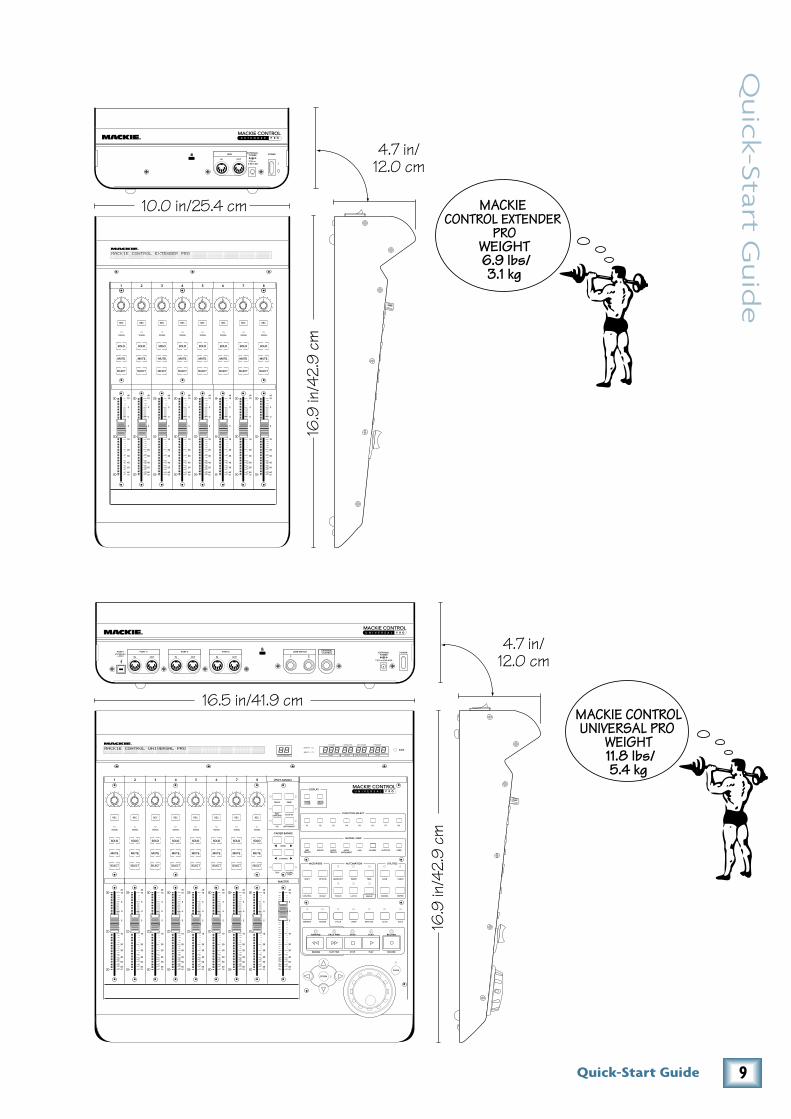
The MCU Pro weighs 11.8 pounds (5.4 kg) and the MCE Pro weighs 6.9 pounds (3.1 kg), so be sure to select a mounting arm or plate that can support the weight of the unit.
Many VESA mounts are designed for video monitors, and the mounting plate is perpindicular to your desktop surface. Since you most likely do not want the MCU Pro to be mounted perpin-
dicular to your desktop, make sure your VESA mount is flexible enough so if it can be properly adjusted for your working space.
MCU Pro or MCE Pro
Mounting Plate
0.153 in/3.88 mmThread Engagement(8 places)
Mounting Plate Thickness + 0.25 in = length of screw
M4 (4 mm) Pemnut(8 places)
0.868 in/22.06 mmClearance for MCU Pro0.469 in/11.91 mmClearance for MCE Pro

�Quick-Start Guide
Qu
ick-S
tart G
uid
e
Mackie Control Extender Pro Mackie Control Extender ProMackie Control Universal Pro
IN OUT IN 1 2OUT
EXTERNALPOWER
POWERPORT 3 PORT 4 EXTERNALCONTROLUSER SWITCH
7.5V 3.0A-4.0A
IN OUT
PORT 2PORT1(INTERNAL)
= MCU IN OUT
MIDI EXTERNALPOWER POWER
3.0A-4.0A7.5V
IN OUT
MIDI EXTERNALPOWER POWER
3.0A-4.0A7.5V
Multiport MIDI Interface
MIDIOUT
MIDIIN
Computer Serial or USB Connection
Digital Audio Workstation
MIDIOUT
MIDIIN
MIDIOUT
MIDIIN
Mackie Control Extender Pro Mackie Control Extender Pro Mackie Control C4 ProMackie Control Universal Pro
IN OUT IN 1 2OUT
EXTERNALPOWER
POWERPORT 3 PORT 4 EXTERNALCONTROLUSER SWITCH
7.5V 3.0A-4.0A
IN OUT
PORT 2PORT1(INTERNAL)
= MCU IN OUT
MIDI EXTERNALPOWER POWER
3.0A-4.0A7.5V
IN OUT
MIDI EXTERNALPOWER POWER
3.0A-4.0A7.5V
IN OUT
MIDI EXTERNALPOWER POWER
3.0A-4.0A7.5V
USB Connection
Digital Audio Workstation
This setup provides the ultimate in DAW control: 24 faders with 24 V-Pots, plus 32 additional V-Pots for dedicated plug-in editing.
You can purchase short MIDI cables to connect the Mackie Control Extenders and C4 to the Mackie Control Universal and keep your cabling neat and tidy.
MIDIOUT
MIDIIN
MIDIOUT
MIDIIN
MIDIOUT
MIDIIN
Hookup 1: USB
Hookup 2: MIDI
Hookup Diagrams
Mackie Control Extender ProMackie Control Universal Pro
IN OUT IN 1 2OUT
EXTERNALPOWER
POWERPORT 3 PORT 4 EXTERNALCONTROLUSER SWITCH
7.5V 3.0A-4.0A
IN OUT
PORT 2PORT1(INTERNAL)
= MCU IN OUT
MIDI EXTERNALPOWER POWER
3.0A-4.0A7.5V
USB Connection
Digital Audio Workstation
MIDIOUT
MIDIIN
MIDIOUT
MIDIIN
MIDIOUT
MIDIIN
MIDI Drum Controller MIDI Synth (with Keyboard)
Hookup 3: With Multiple MIDI Devices

� Mackie Control Universal Pro
Macki
e C
on
tro
l U
niv
ers
al
Pro Using the Mackie Control Universal Pro
Although the functions of the knobs and buttons on the MCU Pro will vary depending on which soft-ware application you are using it with, this section provides an overview of the control surface and a general explanation of what it can do.
Channel Strip
1. Touch-Sensitive FadersThese 100 mm optical, touch-sensitive, motor-
ized faders are used to control the channel’s levels, aux returns, MIDI tracks, and master fader levels. The eight faders move relative to the activity of the currently selected bank of on-screen faders.
�. SELECTThis button selects the corresponding channel
for channel-based editing or assignment com-mands.
�. MUTEThe MUTE button turns off the corresponding
channel’s output signal.
�. SOLOPushing a SOLO button isolates that channel’s
output signal to the mix bus in the DAW application.Note: When one or more SOLO buttons are active, the RUDE SOLO LED next to the Time Display lights to let you know that one or more channels are soloed.
�. SIGNALThis LED illuminates when a signal is present
in the corresponding channel.
�. RECThis button arms or disables the corresponding
track for recording.
7. V-PotThe V-Pots serve a dual function on the Mackie
Control, acting as a push-button and a rotary con-trol. When a V-Pot is pressed, it may be used to change modes of operation or to change what ap-pears in the display above the channel strips.
When a V-Pot is rotated, depending on its assigned function, it can be used to adjust a chan-nel’s pan, send level, or plug-in parameters.
The collar surrounding the V-Pot lights up to in-dicate the relative position of the rotation without having to look at your computer.Wrap
8. Scribble StripThis backlit LCD above the channel strips dis-
plays track names, plug-in parameters, and other information depending on the channel strips cur-rent mode of operation.
5
U
5
10
20
30
40
50
60
10dB
5
U
5
10
20
30
40
50
60
10dB
5
U
5
10
20
30
40
50
60
10dB
5
U
5
10
20
30
40
50
60
10dB
5
U
5
10
20
30
40
50
60
10dB
5
U
5
10
20
30
40
50
60
10dB
5
U
5
10
20
30
40
50
60
10dB
5
U
5
10
20
30
40
50
60
10dB
5
U
5
10
20
30
40
50
60
10dB
BANK
CHANNEL
SOLOCYCLE DROP REPLACE CLICK
SIGNAL SIGNAL SIGNAL SIGNAL SIGNAL SIGNAL SIGNAL SIGNAL
FLIP GLOBALVIEW
+
0
–
+
0
–
+
0
–
+
0
–
+
0
–
+
0
–
+
0
–
+
0
–
DISPLAY
MODIFIERS AUTOMATION UTILITIES
CONTROL
SHIFT OPTION READ/OFF WRITE
TOUCH LATCH
TRIM
CANCEL
SMPTEBEATS
ENTER
SAVE UNDO
/ALT
GLOBAL VIEW
FUNCTION SELECT
NAMEVALUE
MIDITRACKS
INPUTS AUDIOTRACKS
AUDIOINSTRUMENT
AUX BUSSES OUTPUTS USER
F1 F2 F3 F4 F5 F6 F7 F8
87654321
MASTER
FADER BANKS
EQ INSTRUMENT
PLUG-IN
TRACK SEND
PAN/SURROUND
VPOT ASSIGN
GROUP
MARKER NUDGE
REC
REWIND FAST FWD PLAYSTOP RECORD
ASSIGNMENT TICKSSUB DIVISIONBEATSBARS
SMPTE
BEATS
HOURS MINUTES SECONDS FRAMES
RUDE SOLO
REWIND FAST FWD PLAYSTOP RECORD
MACKIE CONTROL UNIVERSAL PRO
REC REC REC REC REC REC REC
SCRUB
ZOOM

7Quick-Start Guide
Qu
ick-S
tart G
uid
e
Master Section
9. V-POT ASSIGNThese six buttons are used to assign different
functions to the V-Pots. These usually include Pan, Aux Send, EQ, Plug-In Effects, and Track level.
10. BANKS and CHANNELSPressing the left or right BANK button jumps
over to the next adjacent eight channels on either the left or right side of the current location.• If one or more Mackie Control Extenders are
present, the BANK buttons jump over by 8 times the number of devices present. For ex-ample, if two Mackie Control Extenders are present in addition to the Mackie Control, the BANK buttons will jump 8 x 3 or 24 channels at a time.
• Pressing the left or right CHANNEL button jumps over to the next adjacent channel on ei-ther the left or right side of the current location.
11. Function SelectThe function of these buttons vary, depending
on the DAW application you are using. Place the overlay for your particular DAW application over this section to provide the correct labeling for these buttons, and refer to the documentation for the DAW application that describes how it oper-ates with Mackie Control.
1�. TransportThese standard transport control buttons are
fairly universal in their operation: Rewind, Fast Forward, Stop, Play, and Record.
1�. Jog/Shuttle WheelUse the button to toggle between Jog and Shut-
tle functions for the large wheel. Use the wheel for editing audio in your DAW application.
1�. Zoom and Navigation buttonsThese four arrow buttons and the zoom button
are used to navigate around the graphic editor in your DAW application.
1�. Time DisplayThis display shows the time location of your
project in either SMPTE or BBT format.
1�. Mode LEDIndicates the current mode of operation for the
channel strips.
5
U
5
10
20
30
40
50
60
10dB
5
U
5
10
20
30
40
50
60
10dB
5
U
5
10
20
30
40
50
60
10dB
5
U
5
10
20
30
40
50
60
10dB
5
U
5
10
20
30
40
50
60
10dB
5
U
5
10
20
30
40
50
60
10dB
5
U
5
10
20
30
40
50
60
10dB
5
U
5
10
20
30
40
50
60
10dB
5
U
5
10
20
30
40
50
60
10dB
BANK
CHANNEL
SOLOCYCLE DROP REPLACE CLICK
SIGNAL SIGNAL SIGNAL SIGNAL SIGNAL SIGNAL SIGNAL SIGNAL
FLIP GLOBALVIEW
+
0
–
+
0
–
+
0
–
+
0
–
+
0
–
+
0
–
+
0
–
+
0
–
DISPLAY
MODIFIERS AUTOMATION UTILITIES
CONTROL
SHIFT OPTION READ/OFF WRITE
TOUCH LATCH
TRIM
CANCEL
SMPTEBEATS
ENTER
SAVE UNDO
/ALT
GLOBAL VIEW
FUNCTION SELECT
NAMEVALUE
MIDITRACKS
INPUTS AUDIOTRACKS
AUDIOINSTRUMENT
AUX BUSSES OUTPUTS USER
F1 F2 F3 F4 F5 F6 F7 F8
87654321
MASTER
FADER BANKS
EQ INSTRUMENT
PLUG-IN
TRACK SEND
PAN/SURROUND
VPOT ASSIGN
GROUP
MARKER NUDGE
REC
REWIND FAST FWD PLAYSTOP RECORD
ASSIGNMENT TICKSSUB DIVISIONBEATSBARS
SMPTE
BEATS
HOURS MINUTES SECONDS FRAMES
RUDE SOLO
REWIND FAST FWD PLAYSTOP RECORD
MACKIE CONTROL UNIVERSAL PRO
REC REC REC REC REC REC REC
SCRUB
ZOOM
8 Mackie Control Universal Pro
Macki
e C
on
tro
l U
niv
ers
al
Pro Rear Panel
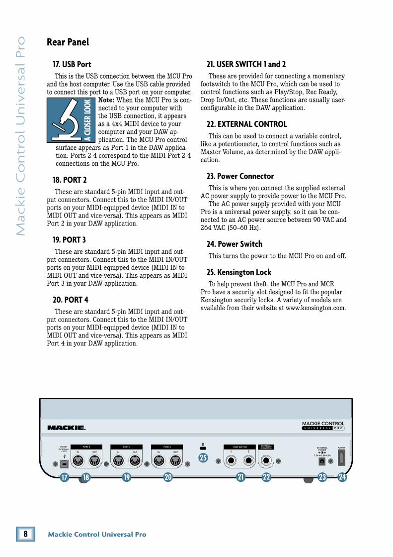
17. USB PortThis is the USB connection between the MCU Pro
and the host computer. Use the USB cable provided to connect this port to a USB port on your computer.
Note: When the MCU Pro is con-nected to your computer with the USB connection, it appears as a 4x4 MIDI device to your computer and your DAW ap-plication. The MCU Pro control
surface appears as Port 1 in the DAW applica-tion. Ports 2-4 correspond to the MIDI Port 2-4 connections on the MCU Pro.
18. PORT �These are standard 5-pin MIDI input and out-
put connectors. Connect this to the MIDI IN/OUT ports on your MIDI-equipped device (MIDI IN to MIDI OUT and vice-versa). This appears as MIDI Port 2 in your DAW application.
19. PORT �These are standard 5-pin MIDI input and out-
put connectors. Connect this to the MIDI IN/OUT ports on your MIDI-equipped device (MIDI IN to MIDI OUT and vice-versa). This appears as MIDI Port 3 in your DAW application.
�0. PORT �These are standard 5-pin MIDI input and out-
put connectors. Connect this to the MIDI IN/OUT ports on your MIDI-equipped device (MIDI IN to MIDI OUT and vice-versa). This appears as MIDI Port 4 in your DAW application.
�1. USER SWITCH 1 and �These are provided for connecting a momentary
footswitch to the MCU Pro, which can be used to control functions such as Play/Stop, Rec Ready, Drop In/Out, etc. These functions are usually user-configurable in the DAW application.
��. EXTERNAL CONTROLThis can be used to connect a variable control,
like a potentiometer, to control functions such as Master Volume, as determined by the DAW appli-cation.
��. Power ConnectorThis is where you connect the supplied external
AC power supply to provide power to the MCU Pro.The AC power supply provided with your MCU
Pro is a universal power supply, so it can be con-nected to an AC power source between 90 VAC and 264 VAC (50–60 Hz).
��. Power SwitchThis turns the power to the MCU Pro on and off.
��. Kensington LockTo help prevent theft, the MCU Pro and MCE
Pro have a security slot designed to fit the popular Kensington security locks. A variety of models are available from their website at www.kensington.com.
IN OUT IN 1 2OUT
EXTERNALPOWER
POWERPORT 3 PORT 4 EXTERNALCONTROLUSER SWITCH
7.5V 3.0A-4.0A
IN OUT
PORT 2PORT1(INTERNAL)
= MCU
9Quick-Start Guide
Qu
ick-S
tart G
uid
e
87654321
5
U
5
10
20
30
40
50
60
10dB
5
U
5
10
20
30
40
50
60
10dB
5
U
5
10
20
30
40
50
60
10dB
5
U
5
10
20
30
40
50
60
10dB
5
U
5
10
20
30
40
50
60
10dB
5
U
5
10
20
30
40
50
60
10dB
5
U
5
10
20
30
40
50
60
10dB
5
U
5
10
20
30
40
50
60
10dB
+
0
–
+
0
–
+
0
–
+
0
–
+
0
–
+
0
–
+
0
–
+
0
–
MACKIE CONTROL EXTENDER PRO
SIGNAL SIGNAL SIGNAL SIGNAL SIGNAL SIGNAL SIGNAL SIGNAL
REC REC REC REC REC REC REC REC
IN OUT
MIDI EXTERNALPOWER POWER
3.0A-4.0A7.5V
10.0 in/25.4 cm
16.9
in/4
2.9
cm
4.7 in/12.0 cm
MACKIE CONTROL EXTENDER
PROWEIGHT 6.9 lbs/
3.1 kg
5
U
5
10
20
30
40
50
60
10dB
5
U
5
10
20
30
40
50
60
10dB
5
U
5
10
20
30
40
50
60
10dB
5
U
5
10
20
30
40
50
60
10dB
5
U
5
10
20
30
40
50
60
10dB
5
U
5
10
20
30
40
50
60
10dB
5
U
5
10
20
30
40
50
60
10dB
5
U
5
10
20
30
40
50
60
10dB
5
U
5
10
20
30
40
50
60
10dB
BANK
CHANNEL
SOLOCYCLE DROP REPLACE CLICK
SIGNAL SIGNAL SIGNAL SIGNAL SIGNAL SIGNAL SIGNAL SIGNAL
FLIP GLOBALVIEW
+
0
–
+
0
–
+
0
–
+
0
–
+
0
–
+
0
–
+
0
–
+
0
–
DISPLAY
MODIFIERS AUTOMATION UTILITIES
CONTROL
SHIFT OPTION READ/OFF WRITE
TOUCH LATCH
TRIM
CANCEL
SMPTEBEATS
ENTER
SAVE UNDO
/ALT
GLOBAL VIEW
FUNCTION SELECT
NAMEVALUE
MIDITRACKS
INPUTS AUDIOTRACKS
AUDIOINSTRUMENT
AUX BUSSES OUTPUTS USER
F1 F2 F3 F4 F5 F6 F7 F8
87654321
MASTER
FADER BANKS
EQ INSTRUMENT
PLUG-IN
TRACK SEND
PAN/SURROUND
VPOT ASSIGN
GROUP
MARKER NUDGE
REC
REWIND FAST FWD PLAYSTOP RECORD
ASSIGNMENT TICKSSUB DIVISIONBEATSBARS
SMPTE
BEATS
HOURS MINUTES SECONDS FRAMES
RUDE SOLO
REWIND FAST FWD PLAYSTOP RECORD
REC REC REC REC REC REC REC
SCRUB
ZOOM
MACKIE CONTROL UNIVERSAL PRO
IN OUT IN OUT IN 1 2OUT
EXTERNALPOWER
POWERPORT 2 PORT 3 PORT 4 EXTERNALCONTROLUSER SWITCH
7.5V 3.0A-4.0A
PORT1(INTERNAL)
= MCU
16.5 in/41.9 cm
16.9
in/4
2.9
cm
MACKIE CONTROLUNIVERSAL PRO
WEIGHT 11.8 lbs/5.4 kg
4.7 in/12.0 cm

10 Mackie Control Universal Pro
Macki
e C
on
tro
l U
niv
ers
al
Pro Service
If you think your Mackie Control Universal Pro or Mackie Control Extender Pro has a problem, please do everything you can to confirm it before calling for service. Visit the Support section of our website (www.mackie.com/support) where you will find lots of useful information such as FAQs, documentation, and user forums. You may find the answer to the problem without having to send your Mackie Control away.
If the problem is related to setting up and using Mackie Control with your DAW software, contact your software manufacturer’s technical support.
If you are absolutely, positively sure it is a hard-ware related problem, then go to the repair section next for further instructions.
RepairService for Mackie products purchased in the
USA is available at a factory-authorized service center. Service for Mackie products living outside the United States can be obtained through local dealers or distributors.
If your Mackie Control Universal Pro or Mackie Control Extender Pro needs service, and it lives in the United States, follow these instructions:1. Call Tech Support at 1-800-898-3211, 7 am to
5 pm PST, to explain the problem and obtain a Service Request Number. Have your Mackie Control Universal Pro or Mackie Control Ex-tender Pro serial number ready. You must have a Service Request Number before you can obtain service at the factory.
2. Keep this quick-start guide. We don’t need it to repair the controller.
3. Pack the controller in its original package, including endcaps and box. This is very impor-tant. When you call for the Service Request Number, please let Tech Support know if you need new packaging. Mackie is not responsible for any damage that occurs due to non-factory packaging.
4. Include a legible note stating your name, ship-ping address (no P.O. boxes), daytime phone number, Service Request Number, and a de-tailed description of the problem, including how we can duplicate it.
5. Write the Service Request Number in BIG PRINT on top of the box. Units sent without the Service Request Number will be refused.
6. Tech Support will tell you where to ship the controller for repair. We suggest insurance for all forms of cartage.
7. You will need to contact the authorized service center for their latest turn-around times when you call for your Service Request Number. The controller must be packaged in its original packing box, and must have the Service Re-quest Number on the box. Once it’s repaired, the authorized service center will ship it back prepaid (if it was a warranty repair).
Note: Under the terms of the warranty, you must ship or drop-off the unit to an authorized service center. The return ground shipment is covered for those units deemed by us to be under warranty.Note: You must have a sales receipt from an Autho-rized Mackie Dealer to qualify for a warranty repair.
Please read the warranty information on page 11, then either register online at www.mackie.com or complete and return the Product Registration card included with your Mackie Control Universal Pro or Mackie Control Extender Pro.
“Mackie.,” the “Running Man” figure, “Mackie Control Universal Pro,” and “Mackie Control Extender Pro” are trademarks or registered trade-marks of LOUD Technologies Inc. All other brand names mentioned are trademarks or registered trademarks of their respective holders, and are hereby acknowledged.
Please write your serial number here for future reference (i.e., insurance claims, tech support, return authorization, etc.) Purchased at: Date of purchase:
R© 2007 LOUD Technologies Inc.All Rights Reserved.

11Quick-Start Guide
Qu
ick-S
tart G
uid
e
MACKIE CONTROL UNIVERSAL PRO and MACKIE CONTROL EXTENDER PRO LIMITED WARRANTY
Please keep your sales receipt in a safe place.
A. LOUD Technologies Inc. warrants all materials, workmanship and proper operation of this product for a period of two years from the original date of purchase. If any defects are found in the materials or workmanship or if the product fails to function properly during the applicable warranty period, LOUD Technologies, at its option, will repair or replace the product. This warranty applies only to equipment sold and delivered within the U.S. by LOUD Technologies Inc. or its authorized dealers.B. Failure to register online or return the product registration card will not void the two-year warranty.C. Service and repairs of Mackie products are to be performed only at an Authorized Mackie Service Center (see D below). Unauthorized service, repairs, or modifications will void this warranty.D. To obtain factory-authorized service:
1. Call LOUD Technologies at 800/898-3211, 7 AM to 5 PM Monday through Friday (Pacific Time) to get a Service Request Number. Products returned without a Service Request Number will be refused. 2. Pack the product in its original shipping carton. Also include a note explaining exactly how to duplicate the problem, a copy of the sales receipt with price and date showing, and your return street address (no P.O. boxes or route numbers, please!). If we cannot duplicate the problem or establish the starting date of your Limited Warranty, we may, at our option, charge for service time.3. Ship the product in its original shipping carton, freight prepaid to the authorized service center. The address of your closest authorized service center will be given to you by Technical Support.
IMPORTANT: Make sure that the Service Request Number is plainly written on the shipping carton.
E. LOUD Technologies reserves the right to in-spect any products that may be the subject of any warranty claims before repair or replacement is carried out. LOUD Technologies may, at our option, require proof of the original date of purchase in the form of a dated copy of the original dealer’s invoice or sales receipt. Final determination of warranty coverage lies solely with LOUD Technologies.F. Any products returned to one of the LOUD Technologies factory-authorized service centers and deemed eligible for repair or replacement un-der the terms of this warranty will be repaired or replaced within thirty days of receipt. LOUD Tech-nologies and its authorized service centers may use refurbished parts for repair or replacement of
any product. Products returned to LOUD Technolo-gies that do not meet the terms of this Warranty will be not be repaired unless payment is received for labor, materials, return freight, and insurance. Products repaired under warranty will be returned freight prepaid by LOUD Technologies to any loca-tion within the boundaries of the USA.G. LOUD Technologies warrants all repairs per-formed for 90 days or for the remainder of the warranty period. This warranty does not extend to damage resulting from improper installation, mis-use, neglect or abuse, or to exterior appearance. This warranty is recognized only if the inspection seals and serial number on the unit have not been defaced or removed.H. LOUD Technologies assumes no responsibility for the quality or timeliness of repairs performed by an authorized service center.I. This warranty is extended to the original pur-chaser and to anyone who may subsequently purchase this product within the applicable war-ranty period. A copy of the original sales receipt is required to obtain warranty repairs.J. This is your sole warranty. LOUD Technologies does not authorize any third party, including any dealer or sales representative, to assume any li-ability on behalf of LOUD Technologies or to make any warranty for LOUD Technologies Inc.K. THE WARRANTY GIVEN ON THIS PAGE IS THE SOLE WARRANTY GIVEN BY LOUD TECHNOLOGIES INC. AND IS IN LIEU OF ALL OTHER WARRANTIES EXPRESS AND IMPLIED, INCLUDING THE WARRANTIES OF MERCHANT-ABILITY AND FITNESS FOR A PARTICULAR PURPOSE. THE WARRANTY GIVEN ON THIS PAGE SHALL BE STRICTLY LIMITED IN DU-RATION TO TWO YEARS FROM THE DATE OF ORIGINAL PURCHASE FROM AN AUTHO-RIZED MACKIE DEALER. UPON EXPIRATION OF THE APPLICABLE WARRANTY PERIOD, LOUD TECHNOLOGIES INC. SHALL HAVE NO FURTHER WARRANTY OBLIGATION OF ANY KIND. LOUD TECHNOLOGIES INC. SHALL NOT BE LIABLE FOR ANY INCIDENTAL, SPECIAL, OR CONSEQUENTIAL DAMAGES THAT MAY RESULT FROM ANY DEFECT IN THE MACKIE PRODUCT OR ANY WARRANTY CLAIM. Some states do not allow exclusion or limitation of in-cidental, special, or consequential damages or a limitation on how long warranties last, so some of the above limitations and exclusions may not apply to you. This warranty provides specific legal rights and you may have other rights which vary from state to state.and you may have other rights which vary from state to state.
16220 Wood-Red Road NE • Woodinville, WA 98072 • USAUnited States and Canada: 800.898.3211Europe, Asia, Central and South America: 425.487.4333Middle East and Africa: 31.20.654.4000Fax: 425.487.4337 • www.mackie.comE-mail: [email protected]