machining science and technology - umbc: an honors ... · pdf filemachining science and...
TRANSCRIPT
This article was downloaded by:[University of Maryland Baltimore County]On: 13 May 2008Access Details: [subscription number 788797246]Publisher: Taylor & FrancisInforma Ltd Registered in England and Wales Registered Number: 1072954Registered office: Mortimer House, 37-41 Mortimer Street, London W1T 3JH, UK
Machining Science and TechnologyAn International JournalPublication details, including instructions for authors and subscription information:http://www.informaworld.com/smpp/title~content=t713597283
MACHINING OF CORTICAL BONE: SURFACETEXTURE, SURFACE INTEGRITY AND CUTTINGFORCESC. Yeager a; A. Nazari a; D. Arola aba Department of Mechanical Engineering, University of Maryland Baltimore County,Baltimore, MDb Department of Endodontics, Prosthodontics, and Operative Dentistry, BaltimoreCollege of Dental Surgery, University of Maryland, Baltimore, MD
Online Publication Date: 01 January 2008
To cite this Article: Yeager, C., Nazari, A. and Arola, D. (2008) 'MACHINING OF CORTICAL BONE: SURFACETEXTURE, SURFACE INTEGRITY AND CUTTING FORCES', Machining Science and Technology, 12:1, 100 — 118
To link to this article: DOI: 10.1080/10910340801890961URL: http://dx.doi.org/10.1080/10910340801890961
PLEASE SCROLL DOWN FOR ARTICLE
Full terms and conditions of use: http://www.informaworld.com/terms-and-conditions-of-access.pdf
This article maybe used for research, teaching and private study purposes. Any substantial or systematic reproduction,re-distribution, re-selling, loan or sub-licensing, systematic supply or distribution in any form to anyone is expresslyforbidden.
The publisher does not give any warranty express or implied or make any representation that the contents will becomplete or accurate or up to date. The accuracy of any instructions, formulae and drug doses should beindependently verified with primary sources. The publisher shall not be liable for any loss, actions, claims, proceedings,demand or costs or damages whatsoever or howsoever caused arising directly or indirectly in connection with orarising out of the use of this material.

Dow
nloa
ded
By:
[Uni
vers
ity o
f Mar
ylan
d B
altim
ore
Cou
nty]
At:
00:5
7 13
May
200
8
MACHINING OF CORTICAL BONE: SURFACE TEXTURE,SURFACE INTEGRITY AND CUTTING FORCES
C. Yeager1, A. Nazari1, and D. Arola1,2
1Department of Mechanical Engineering, University of Maryland Baltimore County,Baltimore, MD2Department of Endodontics, Prosthodontics, and Operative Dentistry, Baltimore Collegeof Dental Surgery, University of Maryland, Baltimore, MD
& Cutting, drilling and reaming of human bone are conducted in total joint replacementprocedures and the placement of dental implants. In the current study orthogonal machiningof cortical bone was performed and the cutting and thrust forces, as well as the machined surfacequality, were evaluated over a range of osteon orientations and cutting conditions. Resultsshowed that cutting perpendicular to the osteons resulted in the highest machining forces, largestsurface roughness and extensive sub-surface damage for some parametric conditions. The averagesurface roughness of the machined bone ranged from 1 lm to over 70 lm, was largest for positiverake angle tools and increased with the depth of cut. There was no correlation between the cut-ting forces and machined surface quality. While negative rake angle tools resulted in the largestcutting forces, they provided the lowest surface roughness and highest apparent surface quality.Overall, the results show that orthogonal cutting of bone can result in near-surface damage thatreduces the degree of contact between bone and implanted devices and is potentially detrimentalto the post-surgical recovery rate.
Keywords Bone, Cutting, Surface texture
INTRODUCTION
Total joint replacements (TJR) and the replacement of lost teeth withdental implants are becoming increasingly common practices. Specifically,the increase in lifespan and rise in obesity have raised the prevalence oftotal joint replacements in this country and others. Between 1992 and2003, the rate of knee replacements doubled and the number of hip
The authors acknowledge that the work described within this manuscript was supported in part bya grant from the Maryland Chapter of the Arthritis Foundation.
Address correspondence to D. Arola, Department of Mechanical Engineering, University ofMaryland Baltimore County, 1000 Hilltop Circle, Baltimore, MD 21250 USA. E-mail: [email protected]
Machining Science and Technology, 12:100–118Copyright # 2008 Taylor & Francis Group, LLCISSN: 1091-0344 print/1532-2483 onlineDOI: 10.1080/10910340801890961
Dow
nloa
ded
By:
[Uni
vers
ity o
f Mar
ylan
d B
altim
ore
Cou
nty]
At:
00:5
7 13
May
200
8
replacements tripled among men and women in the United States aged 45years and over (NIH Consensus, 2003). The success of total joint replace-ment relies on the skills of a well-trained surgeon to remove skeletal tissuesand shape the remaining hard tissue (i.e., machining) as necessary forplacement of the implant. Over the past 3 decades there has been a gradualmovement towards cementless fixation in TJRs where the bone growsdirectly onto the implant’s surface. As such, the surface roughness and sur-face integrity of the machined bone are becoming increasingly important.They govern the nature of early contact between the implant and bone, andlikely contribute to the onset of bone growth and corresponding rate ofrecovery.
Based on its primary constituents, bone can be considered both aceramic and composite material. It is comprised of a high percentage ofcalcium and phosphate based apatitic mineral (i.e., ceramic) and anorganic matrix comprised primarily of type I collagen. These constituentsare arranged in a hierarchical manner that, at least on a microscopic scale,mimics the basic structure of unidirectional composites. A review of themethods used in cutting bone and the mechanics of material removalwas reported by Giraud et al. (1991). Of those methods available to thesurgeon today, bone is typically removed or sectioned using tools with welldefined geometry. Previous studies have identified that material removal inmachining of cortical bone is dependent on the osteon direction.
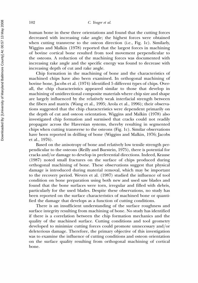
There are three primary orientations of interest that are definedaccording to the osteons and direction of tool movement (Fig. 1). Jacobset al. (1974) conducted orthogonal cutting experiments on bovine and
FIGURE 1 The three independent cutting modes for bone. In (a), (b), and (c) the velocity vector is Vand the osteonal orientation is O. (a) the [0,0] cutting mode, (b) the [0,90] cutting mode, (c) the[90,0] cutting mode.
Machining of Cortical Bone 101
Dow
nloa
ded
By:
[Uni
vers
ity o
f Mar
ylan
d B
altim
ore
Cou
nty]
At:
00:5
7 13
May
200
8
human bone in these three orientations and found that the cutting forcesdecreased with increasing rake angle; the highest forces were obtainedwhen cutting transverse to the osteon direction (i.e., Fig. 1c). Similarly,Wiggins and Malkin (1978) reported that the largest forces in machiningof bovine cortical bone resulted from tool movement perpendicular tothe osteons. A reduction of the machining forces was documented withincreasing rake angle and the specific energy was found to decrease withincreasing depth of cut and rake angle.
Chip formation in the machining of bone and the characteristics ofmachined chips have also been examined. In orthogonal machining ofbovine bone, Jacobs et al. (1974) identified 5 different types of chips. Over-all, the chip characteristics appeared similar to those that develop inmachining of unidirectional composite materials where chip size and shapeare largely influenced by the relatively weak interfacial strength betweenthe fibers and matrix (Wang et al., 1995; Arola et al., 1996); their observa-tions suggested that the chip characteristics were dependent primarily onthe depth of cut and osteon orientation. Wiggins and Malkin (1978) alsoinvestigated chip formation and surmised that cracks could not readilypropagate across the Haversian systems, thereby resulting in segmentedchips when cutting transverse to the osteons (Fig. 1c). Similar observationshave been reported in drilling of bone (Wiggins and Malkin, 1976; Jacobset al., 1976).
Based on the anisotropy of bone and relatively low tensile strength per-pendicular to the osteons (Reilly and Burstein, 1975), there is potential forcracks and=or damage to develop in preferential directions. Indeed, Krause(1987) noted small fractures on the surface of chips produced duringorthogonal machining of bone. These observations suggest that physicaldamage is introduced during material removal, which may be importantto the recovery period. Wevers et al. (1987) studied the influence of toolcondition on bone preparation using both new and used saw blades andfound that the bone surfaces were torn, irregular and filled with debris,particularly for the used blades. Despite these observations, no study hasbeen reported on the surface characteristics of machined bone or quanti-fied the damage that develops as a function of cutting conditions.
There is an insufficient understanding of the surface roughness andsurface integrity resulting from machining of bone. No study has identifiedif there is a correlation between the chip formation mechanics and thequality of the machined surface. Cutting conditions and tool geometrydeveloped to minimize cutting forces could promote unnecessary and=ordeleterious damage. Therefore, the primary objective of this investigationwas to examine the influence of cutting conditions and osteon orientationon the surface quality resulting from orthogonal machining of corticalbone.
102 C. Yeager et al.
Dow
nloa
ded
By:
[Uni
vers
ity o
f Mar
ylan
d B
altim
ore
Cou
nty]
At:
00:5
7 13
May
200
8
MATERIALS AND METHODS
Bovine femurs were obtained from a local slaughterhouse and main-tained in calcium buffered saline at 0�C. The dense cortical bone of bovinefemurs is similar to that of humans and served as an adequate modelmaterial with limited health concerns. The proximal and distal ends ofeach femur were removed, leaving the central section for further proces-sing. Due to the anisotropic structure of cortical bone, it was necessary toconstruct specimens with three independent orientations where the osteonorientation was defined with relation to the tool velocity vector using a pairof angles. Using this convention, orientations of [0,0], [0,90] and [90,0]were machined as outlined in Figures 1a through 1c.
Note that it is unlikely that a surgeon would have a choice of cuttingorientation in any treatment involving removal of bone. Nevertheless, theinvestigation evaluated orientation effects to identify which orientation ofmachining would be most likely to result in process related defects or dam-age. These results would then enable a distinction of (a) what locationswould be mostly likely to have damage in a specific treatment, and (b) iftools with new geometry should be produced for reduction of damageand with respect to what osteon orientation.
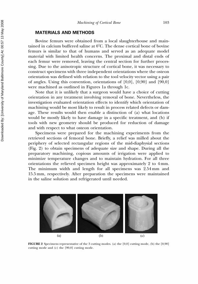
Specimens were prepared for the machining experiments from theretrieved sections of femoral bone. Briefly, a relief was milled about theperiphery of selected rectangular regions of the mid-diaphysial sections(Fig. 2) to obtain specimens of adequate size and shape. During all thepreparatory machining, copious amounts of irrigation were applied tominimize temperature changes and to maintain hydration. For all threeorientations the relieved specimen height was approximately 2 to 4 mm.The minimum width and length for all specimens was 2.54 mm and15.5 mm, respectively. After preparation the specimens were maintainedin the saline solution and refrigerated until needed.
FIGURE 2 Specimens representative of the 3 cutting modes. (a) the [0,0] cutting mode, (b) the [0,90]cutting mode and (c) the [90,0] cutting mode.
Machining of Cortical Bone 103

Dow
nloa
ded
By:
[Uni
vers
ity o
f Mar
ylan
d B
altim
ore
Cou
nty]
At:
00:5
7 13
May
200
8
Orthogonal machining experiments were conducted using a conven-tional shaper (Potter and Johnston Co., Model 2235) with 12.7 mmCTCON style tool holder and triangular tool inserts. Uncoated carbideinserts (TPG-322 grade C2) were used and ground to have rake angles of�30, �20, �10, 0, 10, 20, and 30 degrees �0.5�. All tools were producedwith an 11� clearance angle. The tool post was instrumented with a multi-component load cell (Kistler, Model 9601A) with range of �5 kN for thecutting force direction and �2.5 kN for the thrust force direction. The out-put from the multi-component load cells was converted to a voltage, ampli-fied by Kistler type 5010 amplifiers, converted to digital signals using a dataacquisition board and then acquired and stored using a dedicated com-puter with commercial software. Three signals were recorded simul-taneously including time, cutting force and thrust force. The reactionforces, including the cutting and thrust components, were monitored overa length of stable cutting and the average of each component was estimatedover the respective force history. As such, the forces used in interpretingparametric dependence were the average values for all aspects of theinvestigation unless specified otherwise.
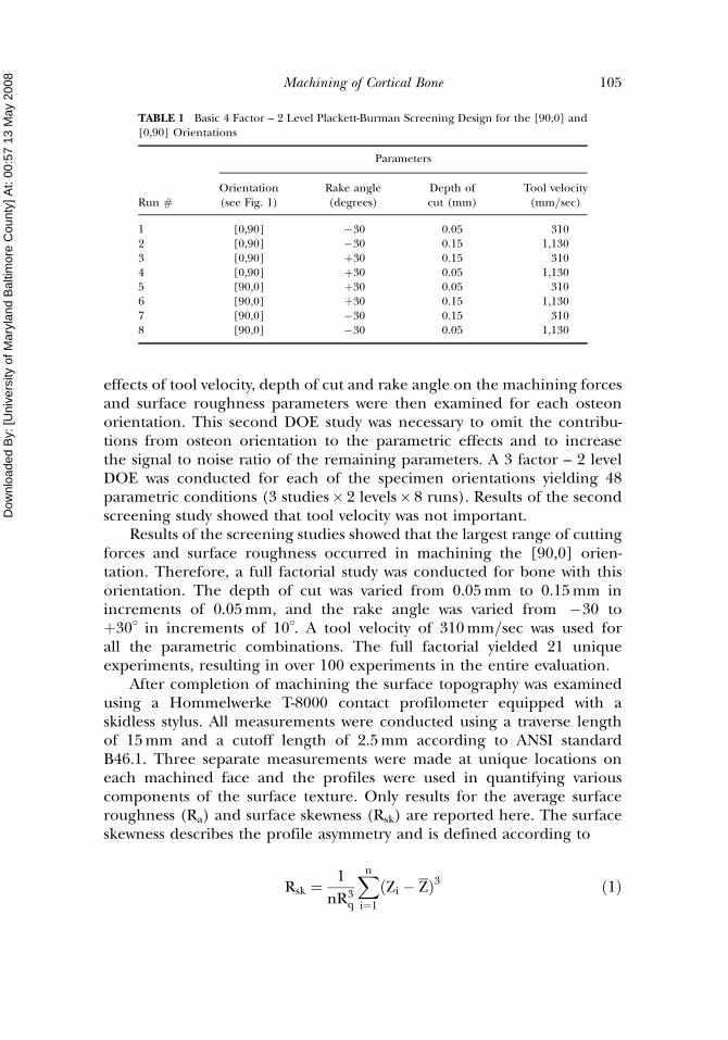
The cutting experiments were conducted through a combination ofthree separate Design of Experiments (DOE). Based on the anisotropy ofbone, an initial DOE comprised of three independent 4 factor – 2 levelscreening studies (Wheeler, 1989) was conducted first to rank the influenceof specimen orientation, in comparison to the remaining machining para-meters, on the cutting process. Basic and reflected studies were conducted,culminating in a total of 48 parametric combinations (3 studies� 2 levels� 8runs). The independent variables for these studies were the tool velocity,the rake angle, and the depth of cut. The fourth factor was the specimenorientation and was comprised of a pair of the two unique orientations.The first study compared specimens with [90,0] and [0,90] orientations,the second compared [0,0] and [0,90] orientations, and the third compared[90,0] and [0,0] orientations. An example of the basic 8-run DOE for the[90,0] [0,90] study is shown in Table 1; all runs were repeated twice. For eachrun the average cutting and thrust forces were measured and the specificcutting energy1 was estimated; the surface texture resulting from machin-ing was also analyzed. An analysis of variance (ANOVA) was conductedwith the results to distinguish the relative importance of the independentvariables on the dependent variable of interest.
After completion of the first DOE, a secondary screening study wasperformed for each osteon orientation individually to examine the relativeimportance of the cutting parameters on material removal. Specifically, the
1The specific energy is obtained from the ratio of the average principal cutting force (over thespecimen length) to the product of the width and depth of cut [Shaw, 1991].
104 C. Yeager et al.
Dow
nloa
ded
By:
[Uni
vers
ity o
f Mar
ylan
d B
altim
ore
Cou
nty]
At:
00:5
7 13
May
200
8
effects of tool velocity, depth of cut and rake angle on the machining forcesand surface roughness parameters were then examined for each osteonorientation. This second DOE study was necessary to omit the contribu-tions from osteon orientation to the parametric effects and to increasethe signal to noise ratio of the remaining parameters. A 3 factor – 2 levelDOE was conducted for each of the specimen orientations yielding 48parametric conditions (3 studies� 2 levels� 8 runs). Results of the secondscreening study showed that tool velocity was not important.
Results of the screening studies showed that the largest range of cuttingforces and surface roughness occurred in machining the [90,0] orien-tation. Therefore, a full factorial study was conducted for bone with thisorientation. The depth of cut was varied from 0.05 mm to 0.15 mm inincrements of 0.05 mm, and the rake angle was varied from �30 toþ30� in increments of 10�. A tool velocity of 310 mm=sec was used forall the parametric combinations. The full factorial yielded 21 uniqueexperiments, resulting in over 100 experiments in the entire evaluation.
After completion of machining the surface topography was examinedusing a Hommelwerke T-8000 contact profilometer equipped with askidless stylus. All measurements were conducted using a traverse lengthof 15 mm and a cutoff length of 2.5 mm according to ANSI standardB46.1. Three separate measurements were made at unique locations oneach machined face and the profiles were used in quantifying variouscomponents of the surface texture. Only results for the average surfaceroughness (Ra) and surface skewness (Rsk) are reported here. The surfaceskewness describes the profile asymmetry and is defined according to
Rsk ¼1
nR3q
Xn
i¼1
ðZi � ZÞ3 ð1Þ
TABLE 1 Basic 4 Factor – 2 Level Plackett-Burman Screening Design for the [90,0] and[0,90] Orientations
Parameters
Run #
Orientation(see Fig. 1)
Rake angle(degrees)
Depth ofcut (mm)
Tool velocity(mm=sec)
1 [0,90] �30 0.05 3102 [0,90] �30 0.15 1,1303 [0,90] þ30 0.15 3104 [0,90] þ30 0.05 1,1305 [90,0] þ30 0.05 3106 [90,0] þ30 0.15 1,1307 [90,0] �30 0.15 3108 [90,0] �30 0.05 1,130
Machining of Cortical Bone 105
Dow
nloa
ded
By:
[Uni
vers
ity o
f Mar
ylan
d B
altim
ore
Cou
nty]
At:
00:5
7 13
May
200
8
where Rq is the root-mean-square roughness and Zi and Z represent thesurface height of point i and the mean surface height deviation from themean-line, respectively. Surface skewness is important to surface function-ality and area of contact with an implanted device. After examining thesurface topography, the specimens were dried in air for a period of 72hours or greater for an examination using a JEOL JSM-5600 scanning elec-tron microscope (SEM). In addition, selected specimens were notched,split perpendicular to the cutting direction and then examined using theSEM for presence of any sub-surface damage or other important features.
RESULTS
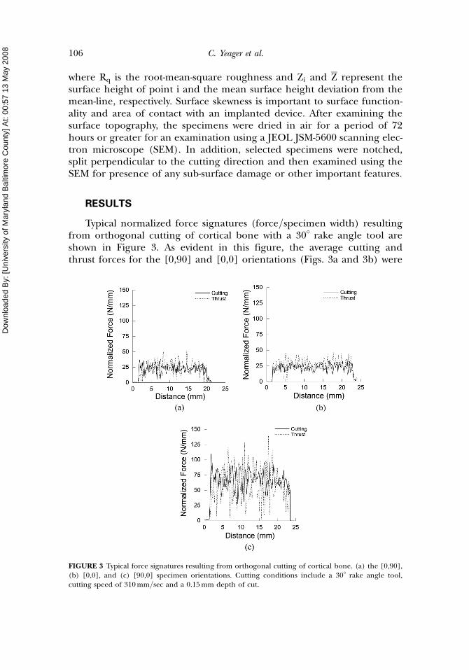
Typical normalized force signatures (force=specimen width) resultingfrom orthogonal cutting of cortical bone with a 30� rake angle tool areshown in Figure 3. As evident in this figure, the average cutting andthrust forces for the [0,90] and [0,0] orientations (Figs. 3a and 3b) were
FIGURE 3 Typical force signatures resulting from orthogonal cutting of cortical bone. (a) the [0,90],(b) [0,0], and (c) [90,0] specimen orientations. Cutting conditions include a 30� rake angle tool,cutting speed of 310 mm=sec and a 0.15 mm depth of cut.
106 C. Yeager et al.
Dow
nloa
ded
By:
[Uni
vers
ity o
f Mar
ylan
d B
altim
ore
Cou
nty]
At:
00:5
7 13
May
200
8
noticeably smaller than those obtained for the [90,0] orientation (Fig. 3c).Regardless of osteon orientation, the force signatures exhibited a largedegree of variation with time, suggesting that the chip formation processwas not continuous and consisted of a series of discrete fractures. Note thatthe standard deviation in the cutting and thrust forces for the [90,0] orien-tation (Fig. 3c) are largest of the three orientations. Considering allthe cutting force signatures, the average coefficient of variation (COV) incutting force exceeded 2 and the largest COV was observed to occurin cutting bone with the [90,0] orientation.
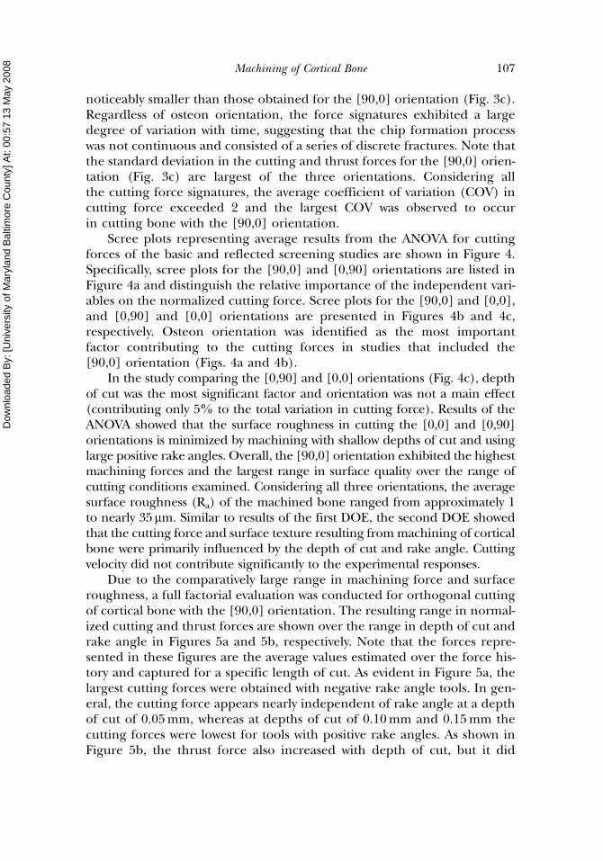
Scree plots representing average results from the ANOVA for cuttingforces of the basic and reflected screening studies are shown in Figure 4.Specifically, scree plots for the [90,0] and [0,90] orientations are listed inFigure 4a and distinguish the relative importance of the independent vari-ables on the normalized cutting force. Scree plots for the [90,0] and [0,0],and [0,90] and [0,0] orientations are presented in Figures 4b and 4c,respectively. Osteon orientation was identified as the most importantfactor contributing to the cutting forces in studies that included the[90,0] orientation (Figs. 4a and 4b).
In the study comparing the [0,90] and [0,0] orientations (Fig. 4c), depthof cut was the most significant factor and orientation was not a main effect(contributing only 5% to the total variation in cutting force). Results of theANOVA showed that the surface roughness in cutting the [0,0] and [0,90]orientations is minimized by machining with shallow depths of cut and usinglarge positive rake angles. Overall, the [90,0] orientation exhibited the highestmachining forces and the largest range in surface quality over the range ofcutting conditions examined. Considering all three orientations, the averagesurface roughness (Ra) of the machined bone ranged from approximately 1to nearly 35mm. Similar to results of the first DOE, the second DOE showedthat the cutting force and surface texture resulting from machining of corticalbone were primarily influenced by the depth of cut and rake angle. Cuttingvelocity did not contribute significantly to the experimental responses.
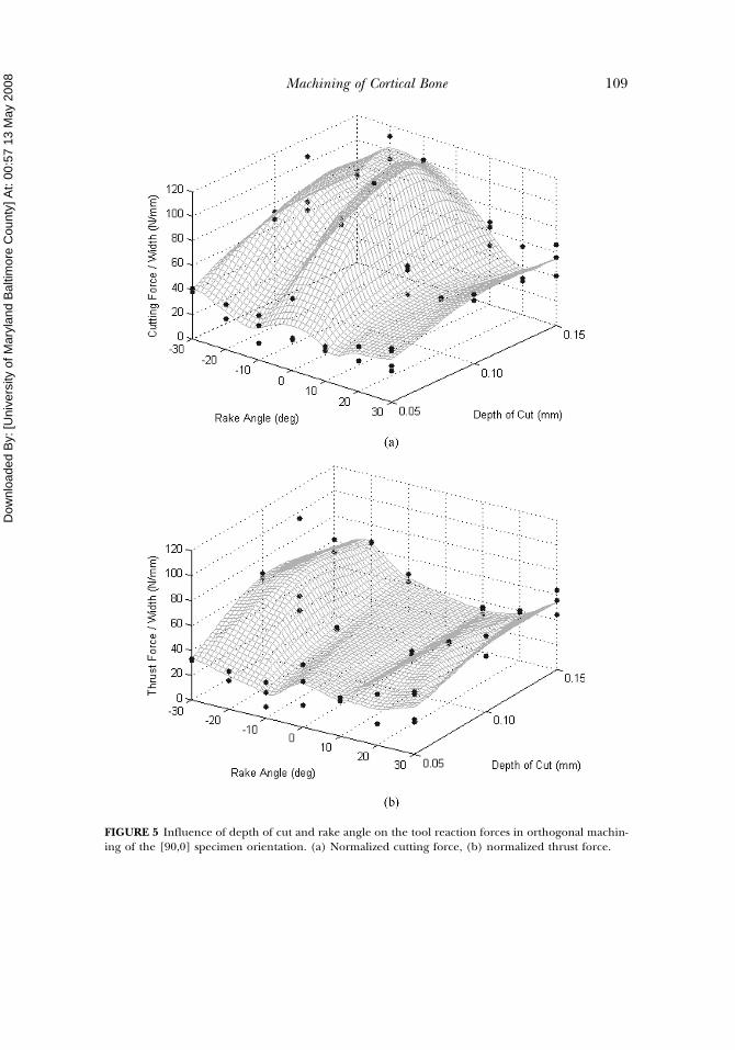
Due to the comparatively large range in machining force and surfaceroughness, a full factorial evaluation was conducted for orthogonal cuttingof cortical bone with the [90,0] orientation. The resulting range in normal-ized cutting and thrust forces are shown over the range in depth of cut andrake angle in Figures 5a and 5b, respectively. Note that the forces repre-sented in these figures are the average values estimated over the force his-tory and captured for a specific length of cut. As evident in Figure 5a, thelargest cutting forces were obtained with negative rake angle tools. In gen-eral, the cutting force appears nearly independent of rake angle at a depthof cut of 0.05 mm, whereas at depths of cut of 0.10 mm and 0.15 mm thecutting forces were lowest for tools with positive rake angles. As shown inFigure 5b, the thrust force also increased with depth of cut, but it did
Machining of Cortical Bone 107
Dow
nloa
ded
By:
[Uni
vers
ity o
f Mar
ylan
d B
altim
ore
Cou
nty]
At:
00:5
7 13
May
200
8
not exhibit the same rake angle dependence as the cutting force distri-bution. Interestingly, the thrust force appeared to be a minimum near 0�
and was maximum for rake angles near þ30� and �30�.
FIGURE 4 Percent contribution of machining variables to cutting force=width as indicated from theANOVA. (a) [90,0] and [0,90] orientations, (b) [90,0] and [0,0] orientations, (c) [0,0] and [0,90] orientations.
108 C. Yeager et al.
Dow
nloa
ded
By:
[Uni
vers
ity o
f Mar
ylan
d B
altim
ore
Cou
nty]
At:
00:5
7 13
May
200
8
FIGURE 5 Influence of depth of cut and rake angle on the tool reaction forces in orthogonal machin-ing of the [90,0] specimen orientation. (a) Normalized cutting force, (b) normalized thrust force.
Machining of Cortical Bone 109
Dow
nloa
ded
By:
[Uni
vers
ity o
f Mar
ylan
d B
altim
ore
Cou
nty]
At:
00:5
7 13
May
200
8
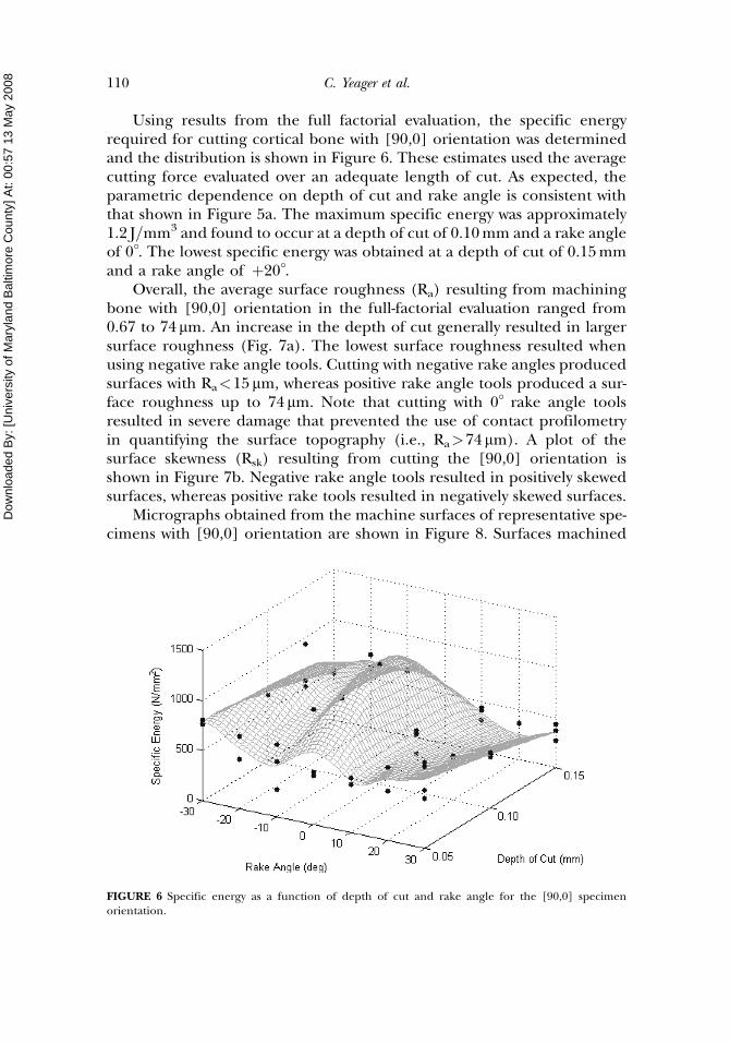
Using results from the full factorial evaluation, the specific energyrequired for cutting cortical bone with [90,0] orientation was determinedand the distribution is shown in Figure 6. These estimates used the averagecutting force evaluated over an adequate length of cut. As expected, theparametric dependence on depth of cut and rake angle is consistent withthat shown in Figure 5a. The maximum specific energy was approximately1.2 J=mm3 and found to occur at a depth of cut of 0.10 mm and a rake angleof 0�. The lowest specific energy was obtained at a depth of cut of 0.15 mmand a rake angle of þ20�.
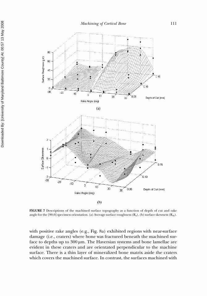
Overall, the average surface roughness (Ra) resulting from machiningbone with [90,0] orientation in the full-factorial evaluation ranged from0.67 to 74 mm. An increase in the depth of cut generally resulted in largersurface roughness (Fig. 7a). The lowest surface roughness resulted whenusing negative rake angle tools. Cutting with negative rake angles producedsurfaces with Ra<15mm, whereas positive rake angle tools produced a sur-face roughness up to 74 mm. Note that cutting with 0� rake angle toolsresulted in severe damage that prevented the use of contact profilometryin quantifying the surface topography (i.e., Ra>74mm). A plot of thesurface skewness (Rsk) resulting from cutting the [90,0] orientation isshown in Figure 7b. Negative rake angle tools resulted in positively skewedsurfaces, whereas positive rake tools resulted in negatively skewed surfaces.
Micrographs obtained from the machine surfaces of representative spe-cimens with [90,0] orientation are shown in Figure 8. Surfaces machined
FIGURE 6 Specific energy as a function of depth of cut and rake angle for the [90,0] specimenorientation.
110 C. Yeager et al.
Dow
nloa
ded
By:
[Uni
vers
ity o
f Mar
ylan
d B
altim
ore
Cou
nty]
At:
00:5
7 13
May
200
8
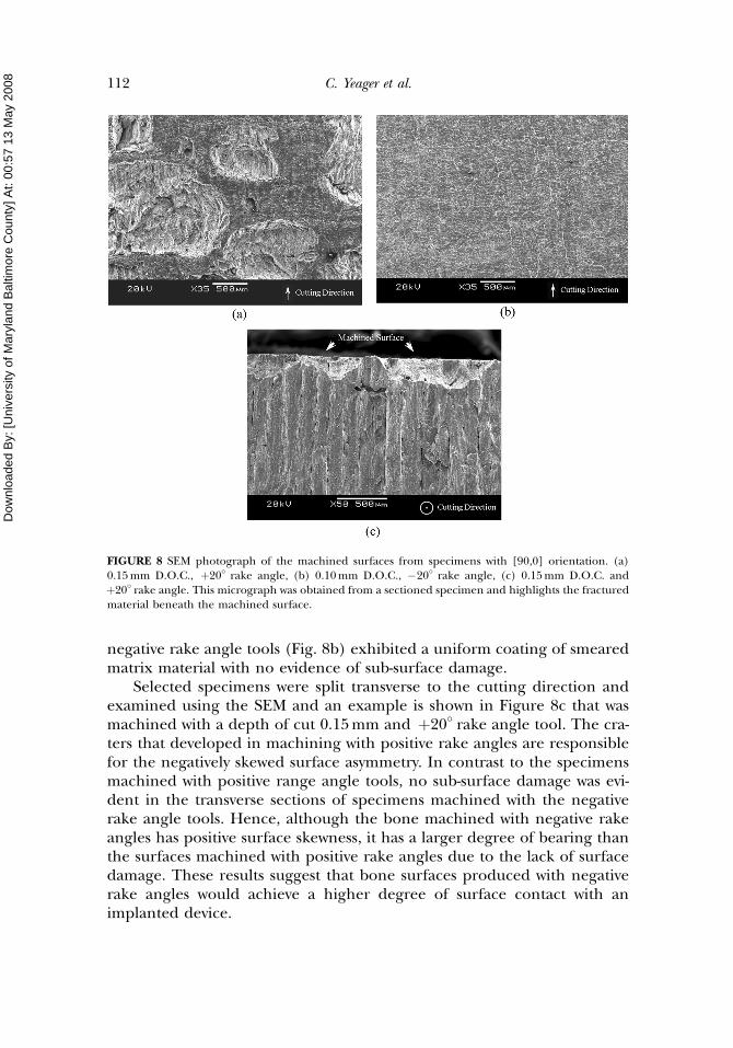
with positive rake angles (e.g., Fig. 8a) exhibited regions with near-surfacedamage (i.e., craters) where bone was fractured beneath the machined sur-face to depths up to 300 mm. The Haversian systems and bone lamellae areevident in these craters and are orientated perpendicular to the machinesurface. There is a thin layer of mineralized bone matrix aside the craterswhich covers the machined surface. In contrast, the surfaces machined with
FIGURE 7 Descriptions of the machined surface topography as a function of depth of cut and rakeangle for the [90,0] specimen orientation. (a) Average surface roughness (Ra), (b) surface skewness (Rsk).
Machining of Cortical Bone 111
Dow
nloa
ded
By:
[Uni
vers
ity o
f Mar
ylan
d B
altim
ore
Cou
nty]
At:
00:5
7 13
May
200
8
negative rake angle tools (Fig. 8b) exhibited a uniform coating of smearedmatrix material with no evidence of sub-surface damage.
Selected specimens were split transverse to the cutting direction andexamined using the SEM and an example is shown in Figure 8c that wasmachined with a depth of cut 0.15 mm and þ20� rake angle tool. The cra-ters that developed in machining with positive rake angles are responsiblefor the negatively skewed surface asymmetry. In contrast to the specimensmachined with positive range angle tools, no sub-surface damage was evi-dent in the transverse sections of specimens machined with the negativerake angle tools. Hence, although the bone machined with negative rakeangles has positive surface skewness, it has a larger degree of bearing thanthe surfaces machined with positive rake angles due to the lack of surfacedamage. These results suggest that bone surfaces produced with negativerake angles would achieve a higher degree of surface contact with animplanted device.
FIGURE 8 SEM photograph of the machined surfaces from specimens with [90,0] orientation. (a)0.15 mm D.O.C., þ20� rake angle, (b) 0.10 mm D.O.C., �20� rake angle, (c) 0.15 mm D.O.C. andþ20� rake angle. This micrograph was obtained from a sectioned specimen and highlights the fracturedmaterial beneath the machined surface.
112 C. Yeager et al.
Dow
nloa
ded
By:
[Uni
vers
ity o
f Mar
ylan
d B
altim
ore
Cou
nty]
At:
00:5
7 13
May
200
8
DISCUSSION
An experimental investigation was performed to evaluate the effectsof cutting conditions and osteon orientation on the mechanics ofmaterial removal (i.e., machining forces) and surface quality resulting fromorthogonal cutting of bone.
Machining Forces
Results of the cutting force measurements are consistent with those ofprevious studies (Wiggins et al., 1978; Jacobs et al., 1974) and distinguishedthat the osteon direction is the most important parameter to the cuttingforce when comparisons of material removal involve the [90,0] orientation.The principal cutting forces resulting from machining the [90,0] orien-tation were larger than those measured for both the [0,90] or [0,0] orienta-tions. Furthermore, the full-factorial evaluation showed that cutting forcesdecreased with an increase in the rake angle beyond 0�. These results are inclose agreement with those reported in the aforementioned studies. Whilea direct comparison of the cutting forces with those of previous studies issubject to differences in the tool rake and clearance angles, the magnitudespresented in Figure 5(a) are generally within 10% of those that werereportedly obtained with similar cutting conditions.
Consistent with the results of Wiggins et al. (1978) and Jacobs et al.(1974), the largest thrust forces were obtained when cutting bone withthe [90,0] orientation. Bone has a comparatively low transverse modulus,thereby resulting in smaller reaction forces as a result of near-tip defor-mation for both the [0,90] and [0,0] orientations. In contrast, the osteonsare oriented perpendicular to the tool path and machined surface in the[90,0] orientation and exist essentially as concentric columns of apatiticmineral embodied by an organic matrix. Thus, the highest thrust forcesfor the [90,0] orientation are likely attributed to the larger stiffness ofthe osteons in the thrust direction and the extent of reaction force onthe tool imposed by elastic recovery.
Surface Topography
The maximum average surface roughness resulting from machiningspecimens with [0,0] and [0,90] osteon orientations was 10 and 12 mm,respectively. In these two orientations the osteons lie in plane with the cut-ting edge of the tool. As the diameter of an osteon ranges from approxi-mately 100mm to nearly 300 mm (Currey, 1982; Weiner et al., 1999;Corwin, 2001), the variation in surface height is limited to far less thana single osteon. Overall, the results showed that the surface roughness
Machining of Cortical Bone 113
Dow
nloa
ded
By:
[Uni
vers
ity o
f Mar
ylan
d B
altim
ore
Cou
nty]
At:
00:5
7 13
May
200
8
resulting from cutting the [0,0] and [0,90] orientations is minimizedby machining at shallow depths of cut and by using large positive rakeangles.
In cutting the [90,0] orientation the maximum surface roughnessrecorded was nearly 75mm. The larger roughness was primarily attributedto sub-surface damage that was introduced in the form of fractured craters(e.g., Fig. 8c) and that extended to nearly 300 mm below the machined sur-face. In this orientation material removal requires fracture transverse to theosteon longitudinal axis, the direction of largest tensile and compressivestrength (Reilly and Burstein, 1975). It appears that intrinsic defects andthe cement lines (between the osteons) serve as paths for sub-surface frac-ture (beneath the tool edge), development of the craters and correspond-ing larger roughness. These results suggest that tool designs targeted tominimize near and sub-surface damage in machining of bone with allorientations should be focused on the geometry that is most beneficialfor the [90,0] orientation.
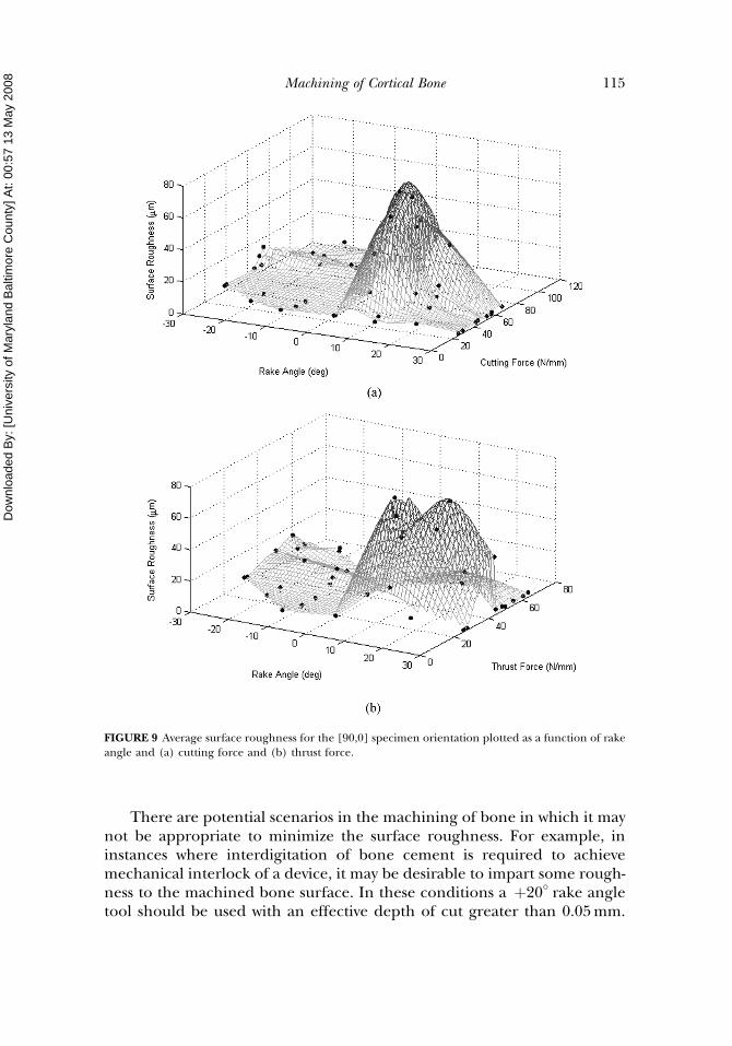
The distribution in Ra of the bone with [90,0] orientation is presentedwith respect to the cutting and thrust forces in Figures 9a and 9b, respec-tively. Note that there is no apparent correlation between the cutting forceor the thrust force and the corresponding surface roughness. Yet, there is adistinct transition in the surface roughness at the onset of cutting with posi-tive rake angles. Regardless of the depth of cut, positive rake angle toolsproduced larger surface roughness through the introduction of sub-surfacefractures. Tools with negative rake angles smeared mineralized bone matrixover the surface, which may have obscured any damage that developed, butresulted in low surface roughness. It is expected that the distinct changein roughness with use of positive rake angles occurs by a transition in thecutting mechanisms. Negative rake angle tools induce microbucklingand crushing of the osteons. In contrast, positive rake angle tools inducea tensile axial component of loading on the osteons that initiates fractureat a sub-surface defect and enables removal through progression of fracturealong the cement lines. Although the fractured craters provided physicalevidence of sub-surface damage, there may be less noticeable forms of dam-age (i.e., cracks) that were introduced as well in the use of both positive andnegative rake angle tools. There has been debate concerning the degree ofacceptable microdamage in bone that can be adequately repaired duringremodeling and that will not grow in length to an extent that promotesexcessive pain and=or leads to stress fractures (Martin et al., 1998). Never-theless, an increase in the degree of cutting-related damage that resultsfrom an orthopedic procedure will prolong the required period of recoverynecessary before load bearing activity. With this in mind, the experimentalresults suggest that cutting tools with negative rake angles may be mosteffective for minimizing the recovery period.
114 C. Yeager et al.
Dow
nloa
ded
By:
[Uni
vers
ity o
f Mar
ylan
d B
altim
ore
Cou
nty]
At:
00:5
7 13
May
200
8
There are potential scenarios in the machining of bone in which it maynot be appropriate to minimize the surface roughness. For example, ininstances where interdigitation of bone cement is required to achievemechanical interlock of a device, it may be desirable to impart some rough-ness to the machined bone surface. In these conditions a þ20� rake angletool should be used with an effective depth of cut greater than 0.05 mm.
FIGURE 9 Average surface roughness for the [90,0] specimen orientation plotted as a function of rakeangle and (a) cutting force and (b) thrust force.
Machining of Cortical Bone 115
Dow
nloa
ded
By:
[Uni
vers
ity o
f Mar
ylan
d B
altim
ore
Cou
nty]
At:
00:5
7 13
May
200
8
These conditions would result in larger roughness and the specific cuttingenergy would be minimized, thereby limiting the heat generated duringcutting. For surgeries requiring maximum bone=implant contact it wouldbe most appropriate to use negative rake angle tools to achieve minimumsurface roughness. Alternatively, tools with large positive rake angles couldbe used provided that tool wear was not an issue.
This experimental investigation has provided some new findings on thesurface topography resulting from orthogonal machining of cortical bone.Nevertheless, there are some recognized limitations and concerns. Of pri-mary importance, the study was conducted using bone from mature bovineas a model for human bone. While the structure and macroscopic proper-ties of human and bovine bone are similar, there could be differences inthe size and number of defects that influenced the surface quality resultingfrom machining. Therefore, a replication of the investigation in machiningof human bone may be warranted. Also, there are many factors that couldinfluence properties of the bone samples including age of the animal, diet,state of hydration, etc. Some of these factors (e.g., aging and potentialembrittlement) are relevant to human bone and the conditions that maybe experienced in surgical practices, which also warrant further investi-gation. Hydration of the bone is undoubtedly important, but the bone spe-cimens were constantly irrigated during and between experiments. Toolcondition is also expected to be important to the cutting and thrust forceresults as well. A pilot study performed to address tool wear showed that thechange in tool nose radius was limited to less than 20 mm over the repli-cation of cutting conditions explored. Cutting tools that have undergonewear may exhibit different parametric trends in the machined surface top-ography, which could be relevant in the surgical environment where singleprocedure tool use is not practiced.
It should be emphasized that the range in cutting conditionsexplored (tool angles, tool velocity, depth of cut, etc.) were representativeof conditions involved in the use of current surgical tools. There are con-ditions that may fall outside of this range and that potentially exhibit adifferent extent of parametric dependence. Further studies should con-sider a larger parametric space if an optimization is attempted. Last,due to the irregular shape of bones and consequent variability in struc-ture, the osteon orientation and its alignment could deviate within anerror of roughly 10�. Thus, there could be some small variation in cuttingorientation that contributed to the results. Despite these limitations, thepresent study has distinguished the relative relationship between cuttingmechanics and surface quality in the machining of bone. Further evalu-ation and understanding could facilitate the design of tools foroptimizing surface integrity that minimizes recovery times and patientdiscomfort.
116 C. Yeager et al.
Dow
nloa
ded
By:
[Uni
vers
ity o
f Mar
ylan
d B
altim
ore
Cou
nty]
At:
00:5
7 13
May
200
8
CONCLUSIONS
An experimental investigation of the surface roughness and surfaceintegrity resulting from orthogonal machining of cortical bone was conduc-ted. According to results of the investigation the following conclusions weredrawn:
(1) In a comparison of machining bone with [0,0] [0,90] and [90,0] orien-tations, the cutting forces and surface quality of bone with the [90,0]orientation exhibited the largest ranges and were the most sensitiveto changes in the process parameters.
2) The highest average cutting and thrust forces and specific energy wereobtained in machining bone with the [90,0] orientation. The highestcutting and thrust forces were 126 and 118 N=mm, respectively, andthe highest specific energy was 1.2 J=mm3. The lowest cutting and thrustforces were achieved with a þ20� rake angle.
3) The average surface roughness (Ra) of the machined bone ranged from1 to nearly 75mm and specimens [90,0] orientation exhibited the lar-gest Ra. Surfaces of the [90,0] specimens machined with negative rakeangles exhibited the lowest roughness and were covered by a smearedor re-deposited layer of bone matrix. Surfaces machined with positiverake angles were relatively free of debris, but exhibited sub-surfacedamage in the form of fracture pockets.
4) Overall, the results showed that the surface roughness resulting fromcutting the [0,0] and [0,90] orientations is minimized by machiningwith large positive rake angles and at shallow depths of cut.
5) The optimum tool geometry for minimizing cutting forces in machin-ing bone with [90,0] orientation consists of a þ20� rake angle. For high-est surface integrity and minimum surface roughness, cutting should beconducted with either negative rake angles or a þ30� rake angle tooland shallow depth of cut.
ACKNOWLEDGMENTS
The authors wish to acknowledge partial support from the MarylandChapter of the Arthritis Foundation in the form of a new investigatoraward. The author A. Nazari gratefully acknowledges support from theU.S. Department of Education in the form of a GAANN award.
REFERENCES
Arola, D.; Ramulu, M.; Wang, D.H. (1996) Chip formation in orthogonal trimming of graphite=epoxycomposite. Composites, 27A: 121–134.
Cowin, S.C. (2001) Bone Mechanics Handbook, 2nd edition, CRC Press, Boca Raton, FL.
Machining of Cortical Bone 117
Dow
nloa
ded
By:
[Uni
vers
ity o
f Mar
ylan
d B
altim
ore
Cou
nty]
At:
00:5
7 13
May
200
8
Currey, J.D. (1982) Osteons in biomechanical literature. J. Biomech., 15: 717.Giraud, J.-Y.; Villemin, S.; Darmana, R.; Cahuzac, J.-Ph.; Autefage, A.; Morucci, J.-P. (1991) Bone cutting.
Clin. Phys. Physiol. Meas., 12: 1–19.Jacobs, C.H.; Berry, J.T.; Pope, M.H.; Hoaglund, F.T. (1976) A study of the bone machining process—
Drilling. J. Biomech., 9: 343–349.Jacobs, C.H.; Pope, M.H.; Berry, J.T.; Hoaglund, F.T. (1974) A study of the bone machining process—
Orthogonal cutting. J. Biomech., 7: 131–136.Krause, W.R. (1987) Orthogonal bone cutting: Saw design and operating characteristics. J. Biomech. Eng.,
109: 263–271.Martin, R.B.; Burr, D.B.; Sharkey, N.A. (1998) Skeletal Tissue Mechanics, Springer-Verlag, New York.National Institutes of Health. (2003) NIH Consensus Development Conference on Total Knee Replace-
ment, <consensus.nih.gov/2003/2003TotalKneeReplacement117html.htm> .Reilly, D.T.; Burstein, A.H. (1975) The elastic and ultimate properties of compact bone tissue.
J. Biomech., 8: 393–405.Shaw, M.C. (1991) Metal Cutting Principles, Oxford University Press, New York, p. 30.Wang, D.H.; Ramulu, M.; Arola, D. (1995) Orthogonal cutting mechanisms of graphite=epoxy
composite. Part I: Unidirectional laminate. IJMTM, 35: 1623–1638.Weiner, S.; Traub, W.; Wagner, H.D. (1999) Lamellar bone: Structure-function relations. J. Struct. Biol.,
126: 241–255.Wevers, H.W.; Espin, E.; Cooke, T.D.V. (1987) Orthopedic sawblades—A case study. J. Arthroplasty,
2: 43–46.Wheeler, D.J. (1989) Tables of Screening Designs, 2nd edition, SPC Press, Knoxville.Wiggins, K.L.; Malkin, S. (1976) Drilling of bone. J. Biomech., 9: 553–559.Wiggins, K.L.; Malkin, S. (1978) Orthogonal machining of bone. J. Biomech., 100: 122–130.
118 C. Yeager et al.