machined part modelling for catia v5 -...
TRANSCRIPT

AIRBUS AP2257Procedure
Issue: Draft A1 Date: 13 February 2002 Page 1 of 46
Machined Part Modellingfor CATIA V5
Owner’s Approval:
Name : Bruno Maître EMK-TFunction : Head of CATIA V5 methods for French
Team
Airbus 2002 . All rights reserved. This document contains Airbus proprietary information and trade secrets. It shall at all timesremain the property of Airbus; no intellectual property right or licence is granted by Airbus in connection with any informationcontained in it. It is supplied on the express condition that said information is treated as confidential, shall not be used for anypurpose other than that for which it is supplied, shall not be disclosed in whole or in part, to third parties other than the AirbusMembers and Associated Partners, their subcontractors and suppliers (to the extent of their involvement in Airbus projects),without Airbus prior written consent.
Authorization:
Date :
Name : Ulrich SCHUMANN-HINDENBERGFunction : Head of CAD-CAM CM (EMK)
SCOPE:
This document is relative to the modeling and know-how rules necessary with CATIAV5 to design acomplex 5 axis machined part, including manufacturing needs.
The guide contains different steps to define specific geometrical machining features as 2.5 axis, 4axis, and 5 axis pockets, as ribs.
It describes :
- Model organization and structure data
- Rules to follow in case of design changes : How to show and model updated parts.
AIRBUS AP2257Machined Part Modelling for CATIA V5
Issue:Draft A1 Date: 13 February 2002 Page 2 of 46
Table of contents
1 Introduction ............................................................................... 3
2 General recommendations....................................................... 4
2.1 Applicable rules ......................................................................................... 4
2.2 Practical advice.......................................................................................... 5
3 General modelling process...................................................... 6
4 Detailed modelling process per type of difficulty ................ 20
4.1 4 or 5 axis pocket with closed angle...................................................... 20
4.1.1 Producing 2.5 axis pocket................................................................................ 20
4.1.2 Solid definition of 5 axis pocket ...................................................................... 24
4.2 4 or 5 axis pocket with open angle ........................................................ 29
4.2.1 Producing 2.5 axis pocket................................................................................ 29
4.2.2 Producing sloped pocket (4 - 5 axes).............................................................. 34
4.3 Top of stiffener modelling....................................................................... 38
4.4 Boss modelling ........................................................................................ 40
5 Identifying modifications........................................................ 44
5.1 Differences between solids made by layer ........................................... 44
5.2 Difference between solids made by 3D modelling comparison.......... 45
Reference documents ........................................................................................... 46
Group of redaction ................................................................................................ 46
Approval ................................................................................................................. 46
Record of revisions ............................................................................................... 46
AIRBUS AP2257Machined Part Modelling for CATIA V5
Issue:Draft A1 Date: 13 February 2002 Page 3 of 46
1 Introduction
The aim being to:- Obtain exact geometry of the detail part,- Check and validate assemblies,- Facilitate modifications to geometry (design and production),- Avoid recreating additional geometry during the Numerical Control programming
phases (the programmer will as far as possible use the solid defined by the DesignOffice as a basis).
The method deals with general cases.Specific cases will be dealt with during CDBT meetings.
For all definition principles relevant to:- Mean/nominal dimensions,- Major Definition Characteristics,- Drawing set integration (furnishing).
! Consult AP2255, 3D modelling rules for CATIA V5.
! Consult AP2260, Drawing rules for CATIA V5.
AIRBUS AP2257Machined Part Modelling for CATIA V5
Issue:Draft A1 Date: 13 February 2002 Page 4 of 46
2 General recommendations
2.1 Applicable rules
- Modelling is done in CATIAV5 exact solid form (PartDesign Workshop). Theresulting model is a CATPart.
Reminders: The intermediary geometry is created by means of sketches and elementsobtained from the WireFrame & Surface Design workshop. The main contours bear ondefined functional references such as the 3 main planes of the part (XY, ZX & YZplanes).- For parts taken from blanks, modelling must include the draft angles for the sections
of the part not machined (by rework of supplier's contractual drawing).
- The bores are modelled.- The threads and tapings are modelled by standard "holes" features:
• to nominal diameter value for a thread,• to drilling diameter value for a tapping.
- Definition of spot facings: Use the "hole" "counterbored" feature
- Positioning reference systemThe part is modelled in its absolute axis system inside the CATPart modelled by the 3main planes (XY, ZX, YZ).- The curves and surfaces from the SRG (Shape reference group) are defined in the
CAD model. These elements have a property giving the reference of the basic GRFfile. Before any construction work, the validity of the curve or the surface from theSRG must be checked. If the size of the surface is insufficient, a new referencemust be requested from the SRG.
- Abundantly use names and explicit comments during CATIA entity creation (rightclick on preselected entity + properties + feature properties).
- For the definition of a feature, perform the Boolean operations at latest possiblestage in the history in order to be able to change more easily, during a modification,the topology of the latter. On completion of construction, there must be only onePartBody. Integration of restrictions is not dealt with here.
- The construction elements will be located, if possible, on the drawing referenceplanes. Whenever possible, they must belong to sketches positioned on theseplanes. These elements will be constructed as and when the designer needs them.
- Pockets will be modelled by the "pockets" features even for non-canonical shapesand this with the aim of optimising recognition of native features proposed by CATIAV5 in the machining workshop.
- In a "Multi-body" approach, always prefer modelling of 2 bodies for a pocket; onebody containing the definition of the pocket without fillets "assembled" with a bodycontaining the fillet radii. This with the aim of more easily integrating the pocketbottom restrictions.
AIRBUS AP2257Machined Part Modelling for CATIA V5
Issue:Draft A1 Date: 13 February 2002 Page 5 of 46
- Parameterising will be done by constraints on a sketch. Caution: all elements usedin the current sketch must be defined in this current sketch or on a coplanar sketchplane. They must not be taken from surface elements external to the latter.
- Do not create auxiliary co-ordinate systems (Reference axis) used for thepositioning of the elements required for the construction of the part.
2.2 Practical advice
- When you modify an object (adding a fillet radius to a body), do not forget toactivate the "Define in work object" command (Mouse Key 3).
- When you want to delete an entity, take care not to destroy the parents but only theelement in question. Deleting the parents is to be prohibited when the work of thedefinition phase is well under way.
- The fillet radii of the walls of a pocket must not be defined on the sketch but as"fillet" features.
AIRBUS AP2257Machined Part Modelling for CATIA V5
Issue:Draft A1 Date: 13 February 2002 Page 6 of 46
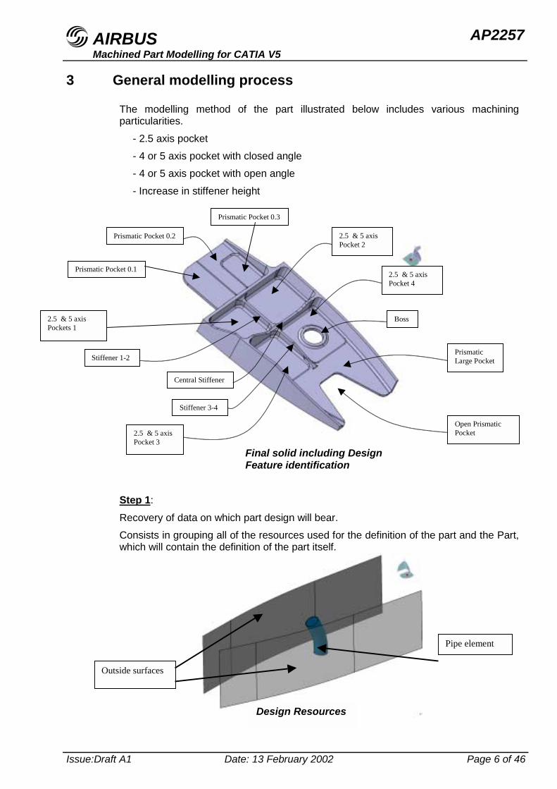
3 General modelling process
The modelling method of the part illustrated below includes various machiningparticularities.
- 2.5 axis pocket- 4 or 5 axis pocket with closed angle- 4 or 5 axis pocket with open angle- Increase in stiffener height
Step 1:
Recovery of data on which part design will bear.Consists in grouping all of the resources used for the definition of the part and the Part,which will contain the definition of the part itself.
Prismatic Pocket 0.3
Final solid including DesignFeature identification
2.5 & 5 axisPockets 1
2.5 & 5 axisPocket 2
PrismaticLarge Pocket
Open PrismaticPocket
Boss
2.5 & 5 axisPocket 3
2.5 & 5 axisPocket 4
Prismatic Pocket 0.1
Prismatic Pocket 0.2
Stiffener 1-2
Stiffener 3-4
Central Stiffener
Pipe element
Outside surfaces
Design Resources
AIRBUS AP2257Machined Part Modelling for CATIA V5
Issue:Draft A1 Date: 13 February 2002 Page 7 of 46
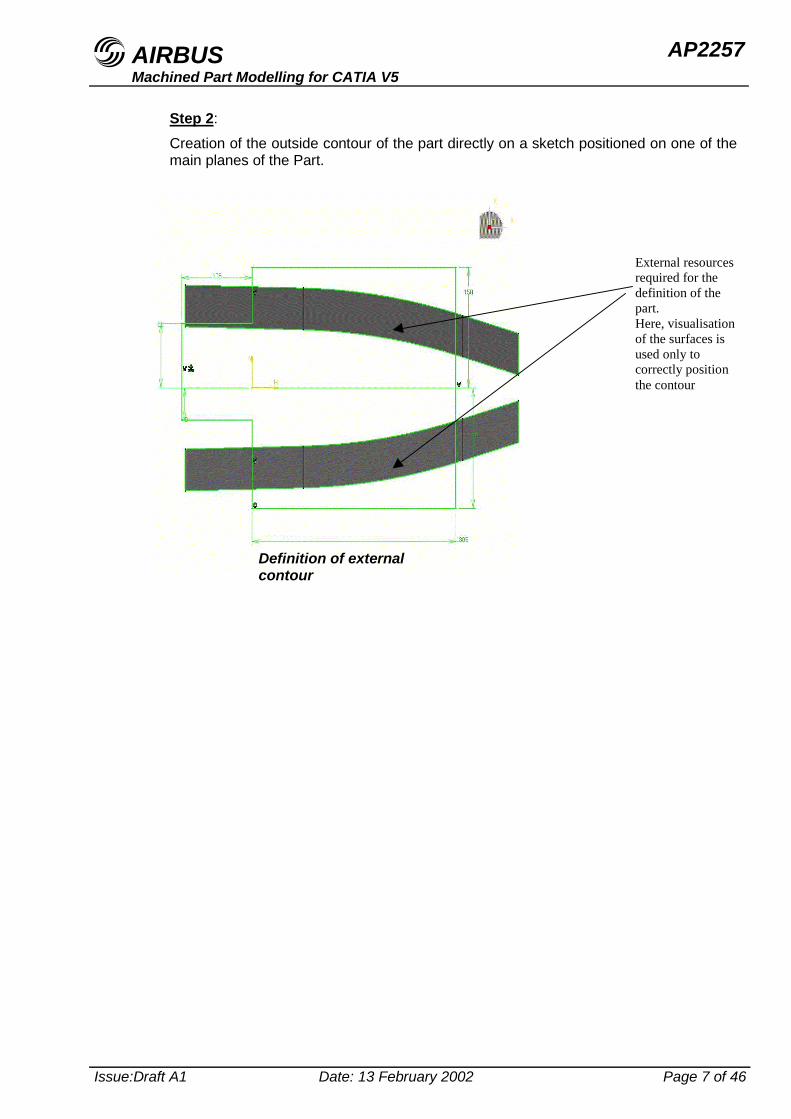
Step 2:Creation of the outside contour of the part directly on a sketch positioned on one of themain planes of the Part.
External resourcesrequired for thedefinition of thepart.Here, visualisationof the surfaces isused only tocorrectly positionthe contour
Definition of externalcontour
AIRBUS AP2257Machined Part Modelling for CATIA V5
Issue:Draft A1 Date: 13 February 2002 Page 8 of 46
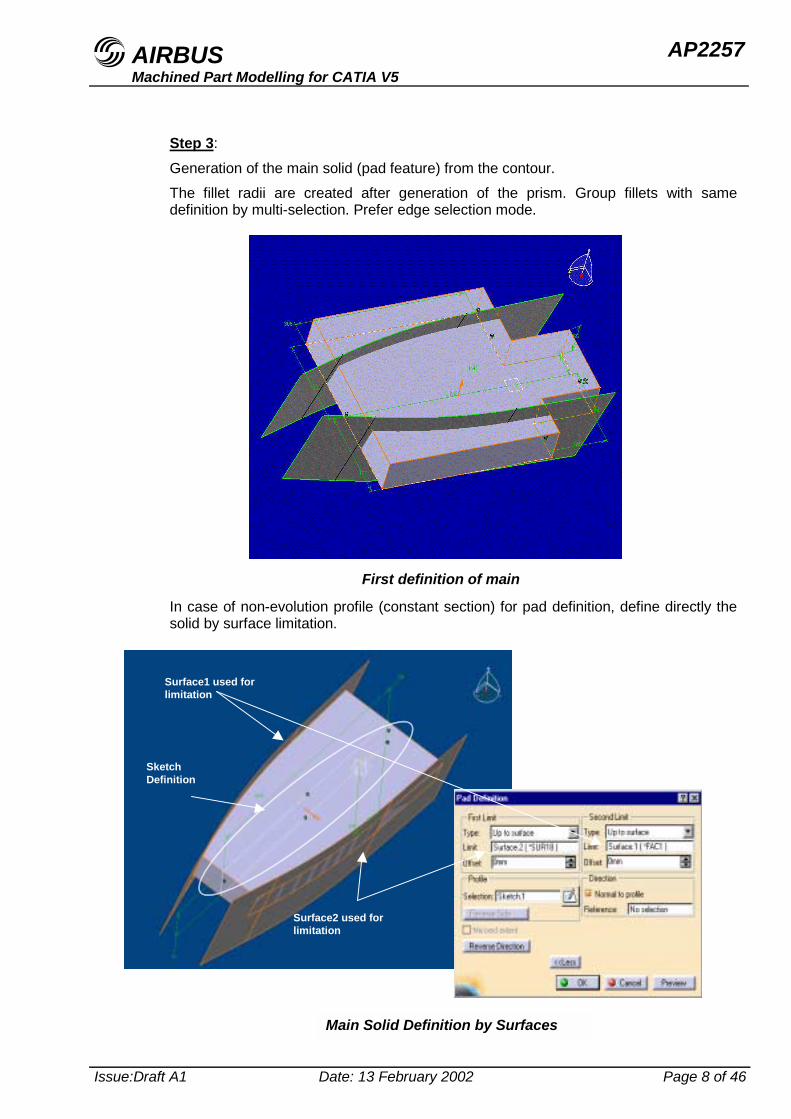
Step 3:
Generation of the main solid (pad feature) from the contour.The fillet radii are created after generation of the prism. Group fillets with samedefinition by multi-selection. Prefer edge selection mode.
In case of non-evolution profile (constant section) for pad definition, define directly thesolid by surface limitation.
First definition of main
Main Solid Definition by Surfaces
SketchDefinition
Surface1 used forlimitation
Surface2 used forlimitation
AIRBUS AP2257Machined Part Modelling for CATIA V5
Issue:Draft A1 Date: 13 February 2002 Page 9 of 46
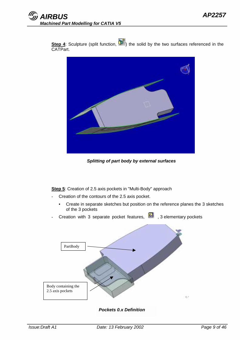
Step 4: Sculpture (split function, ) the solid by the two surfaces referenced in theCATPart.
Step 5: Creation of 2.5 axis pockets in "Multi-Body" approach
- Creation of the contours of the 2.5 axis pocket.
• Create in separate sketches but position on the reference planes the 3 sketchesof the 3 pockets
- Creation with 3 separate pocket features, , 3 elementary pockets
Splitting of part body by external surfaces
PartBody
Body containing the2.5 axis pockets
Pockets 0.x Definition
AIRBUS AP2257Machined Part Modelling for CATIA V5
Issue:Draft A1 Date: 13 February 2002 Page 10 of 46
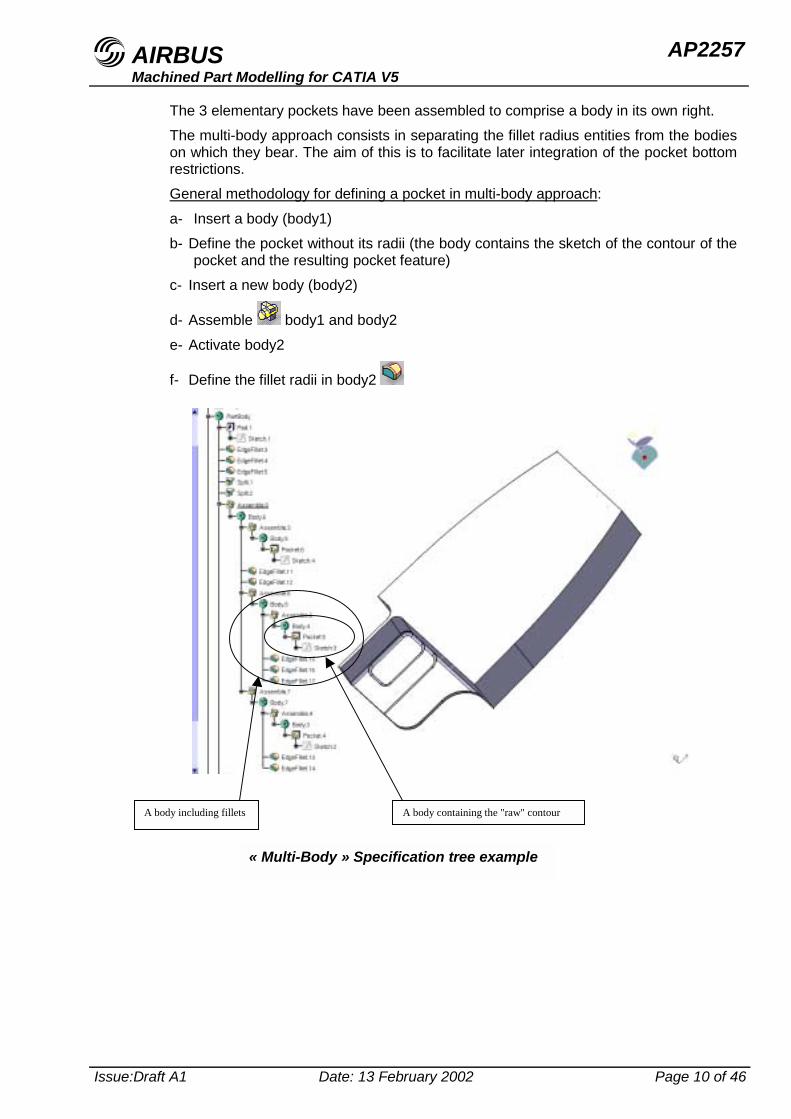
The 3 elementary pockets have been assembled to comprise a body in its own right.The multi-body approach consists in separating the fillet radius entities from the bodieson which they bear. The aim of this is to facilitate later integration of the pocket bottomrestrictions.General methodology for defining a pocket in multi-body approach:a- Insert a body (body1)b- Define the pocket without its radii (the body contains the sketch of the contour of the
pocket and the resulting pocket feature)c- Insert a new body (body2)
d- Assemble body1 and body2e- Activate body2
f- Define the fillet radii in body2
A body including fillets A body containing the "raw" contour
« Multi-Body » Specification tree example
AIRBUS AP2257Machined Part Modelling for CATIA V5
Issue:Draft A1 Date: 13 February 2002 Page 11 of 46
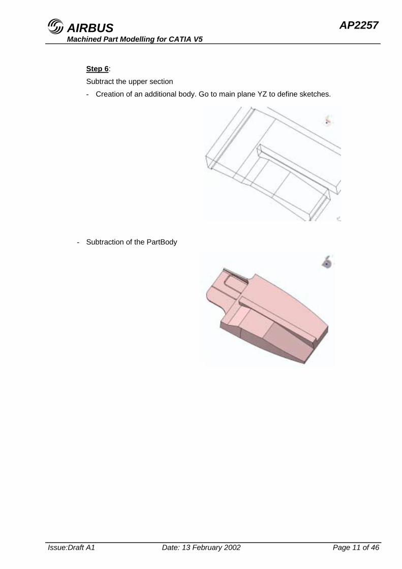
Step 6:
Subtract the upper section- Creation of an additional body. Go to main plane YZ to define sketches.
- Subtraction of the PartBody
AIRBUS AP2257Machined Part Modelling for CATIA V5
Issue:Draft A1 Date: 13 February 2002 Page 12 of 46
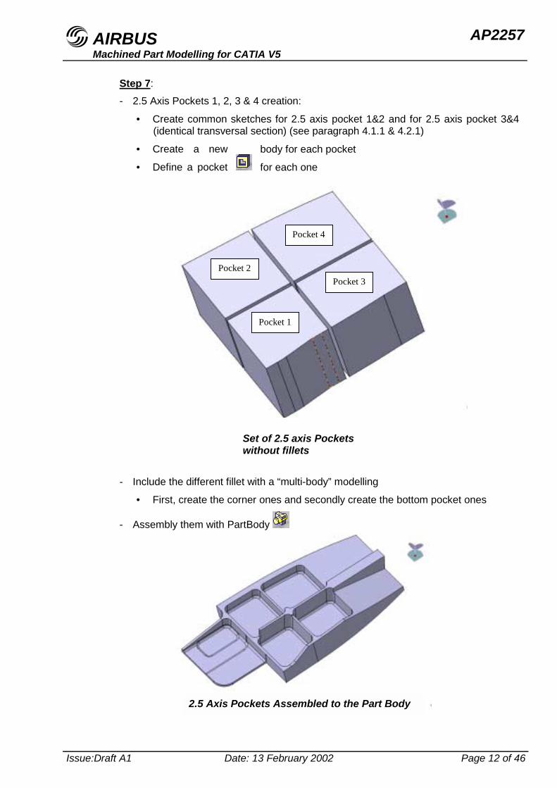
Step 7:- 2.5 Axis Pockets 1, 2, 3 & 4 creation:
• Create common sketches for 2.5 axis pocket 1&2 and for 2.5 axis pocket 3&4(identical transversal section) (see paragraph 4.1.1 & 4.2.1)
• Create a new body for each pocket
• Define a pocket for each one
- Include the different fillet with a “multi-body” modelling
• First, create the corner ones and secondly create the bottom pocket ones
- Assembly them with PartBody
Pocket 1
Pocket 2Pocket 3
Pocket 4
Set of 2.5 axis Pocketswithout fillets
2.5 Axis Pockets Assembled to the Part Body
AIRBUS AP2257Machined Part Modelling for CATIA V5
Issue:Draft A1 Date: 13 February 2002 Page 13 of 46
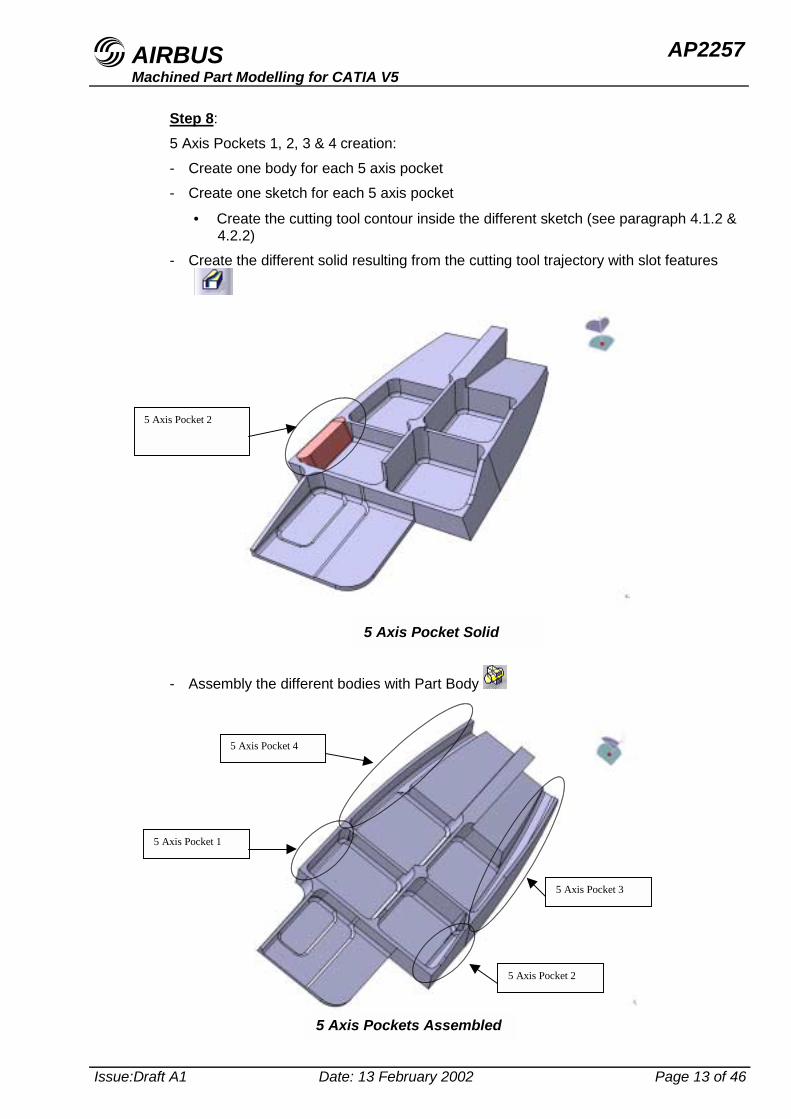
Step 8:5 Axis Pockets 1, 2, 3 & 4 creation:- Create one body for each 5 axis pocket- Create one sketch for each 5 axis pocket
• Create the cutting tool contour inside the different sketch (see paragraph 4.1.2 &4.2.2)
- Create the different solid resulting from the cutting tool trajectory with slot features
- Assembly the different bodies with Part Body
5 Axis Pocket 2
5 Axis Pocket Solid
5 Axis Pocket 1
5 Axis Pocket 2
5 Axis Pocket 3
5 Axis Pocket 4
5 Axis Pockets Assembled
AIRBUS AP2257Machined Part Modelling for CATIA V5
Issue:Draft A1 Date: 13 February 2002 Page 14 of 46
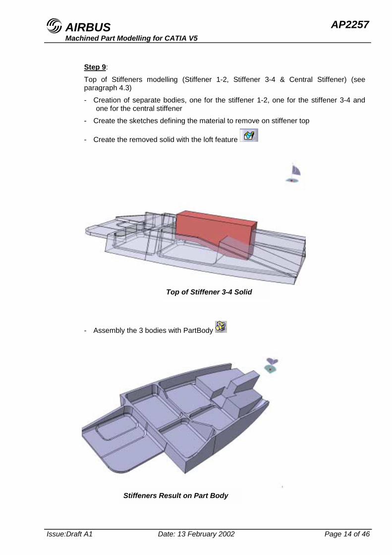
Step 9:
Top of Stiffeners modelling (Stiffener 1-2, Stiffener 3-4 & Central Stiffener) (seeparagraph 4.3)- Creation of separate bodies, one for the stiffener 1-2, one for the stiffener 3-4 and
one for the central stiffener- Create the sketches defining the material to remove on stiffener top
- Create the removed solid with the loft feature
- Assembly the 3 bodies with PartBody
Top of Stiffener 3-4 Solid
Stiffeners Result on Part Body
AIRBUS AP2257Machined Part Modelling for CATIA V5
Issue:Draft A1 Date: 13 February 2002 Page 15 of 46
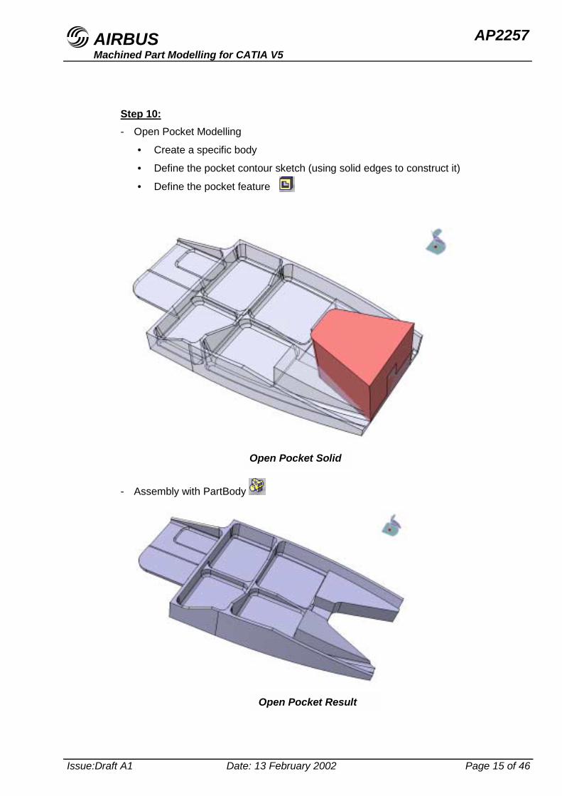
Step 10:- Open Pocket Modelling
• Create a specific body
• Define the pocket contour sketch (using solid edges to construct it)
• Define the pocket feature
- Assembly with PartBody
Open Pocket Solid
Open Pocket Result
AIRBUS AP2257Machined Part Modelling for CATIA V5
Issue:Draft A1 Date: 13 February 2002 Page 16 of 46
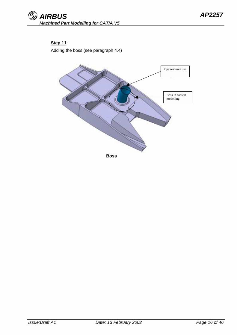
Step 11:
Adding the boss (see paragraph 4.4)
Boss in contextmodelling
Pipe resource use
Boss
AIRBUS AP2257Machined Part Modelling for CATIA V5
Issue:Draft A1 Date: 13 February 2002 Page 17 of 46
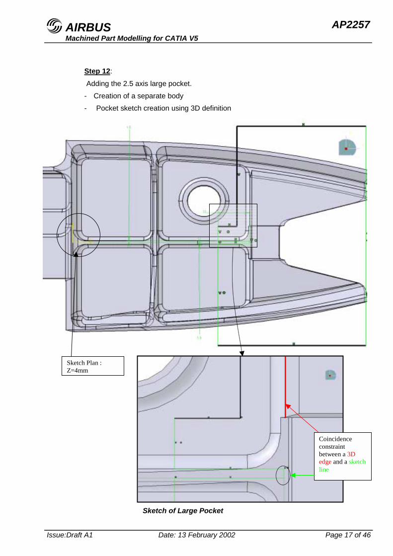
Step 12:
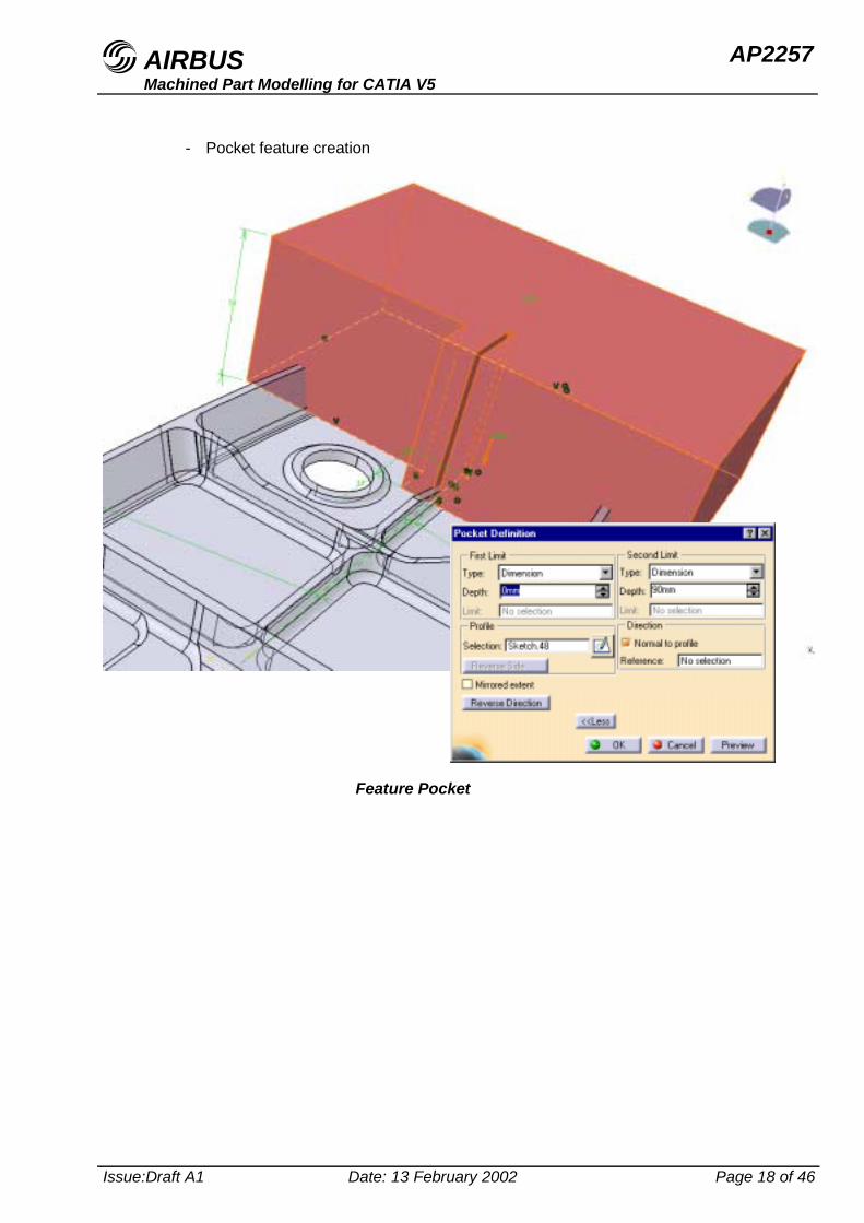
Adding the 2.5 axis large pocket.- Creation of a separate body- Pocket sketch creation using 3D definition
Coincidenceconstraintbetween a 3Dedge and a sketchline
Sketch Plan :Z=4mm
Sketch of Large Pocket
AIRBUS AP2257Machined Part Modelling for CATIA V5
Issue:Draft A1 Date: 13 February 2002 Page 18 of 46
- Pocket feature creation
Feature Pocket
AIRBUS AP2257Machined Part Modelling for CATIA V5
Issue:Draft A1 Date: 13 February 2002 Page 19 of 46
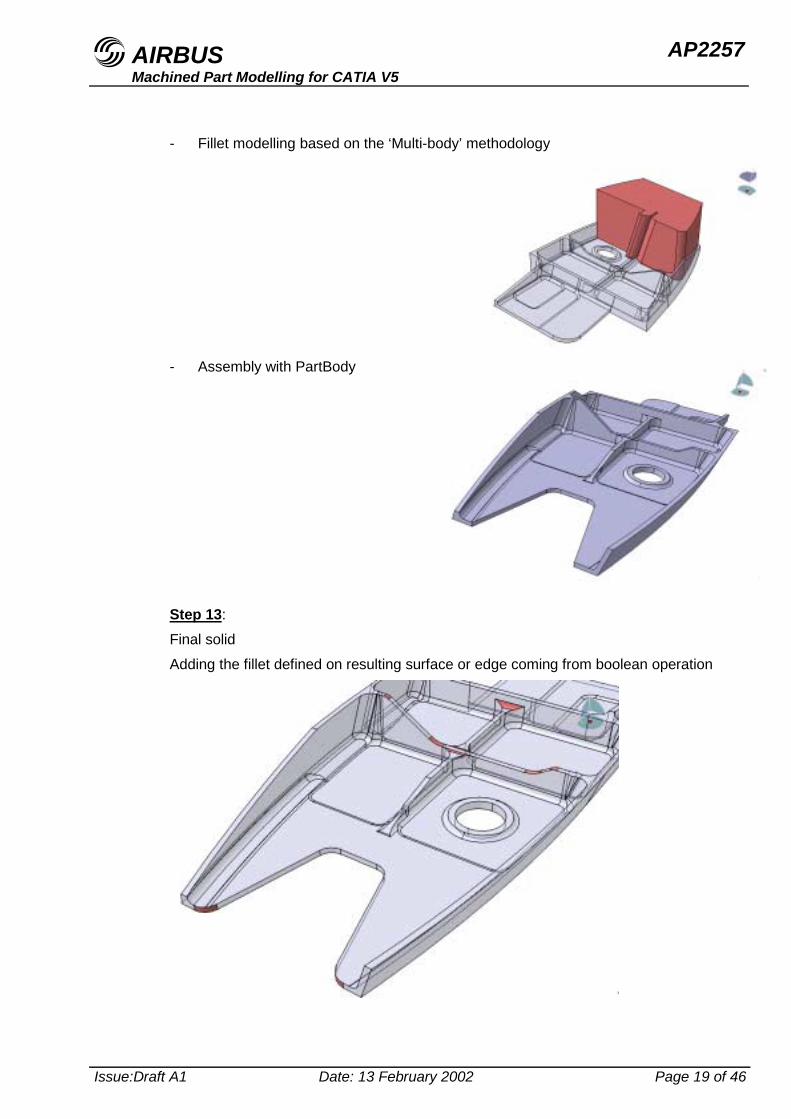
- Fillet modelling based on the ‘Multi-body’ methodology
- Assembly with PartBody
Step 13:Final solidAdding the fillet defined on resulting surface or edge coming from boolean operation
AIRBUS AP2257Machined Part Modelling for CATIA V5
Issue:Draft A1 Date: 13 February 2002 Page 20 of 46
4 Detailed modelling process per type of difficulty
4.1 4 or 5 axis pocket with closed angle
4.1.1 Producing 2.5 axis pocket
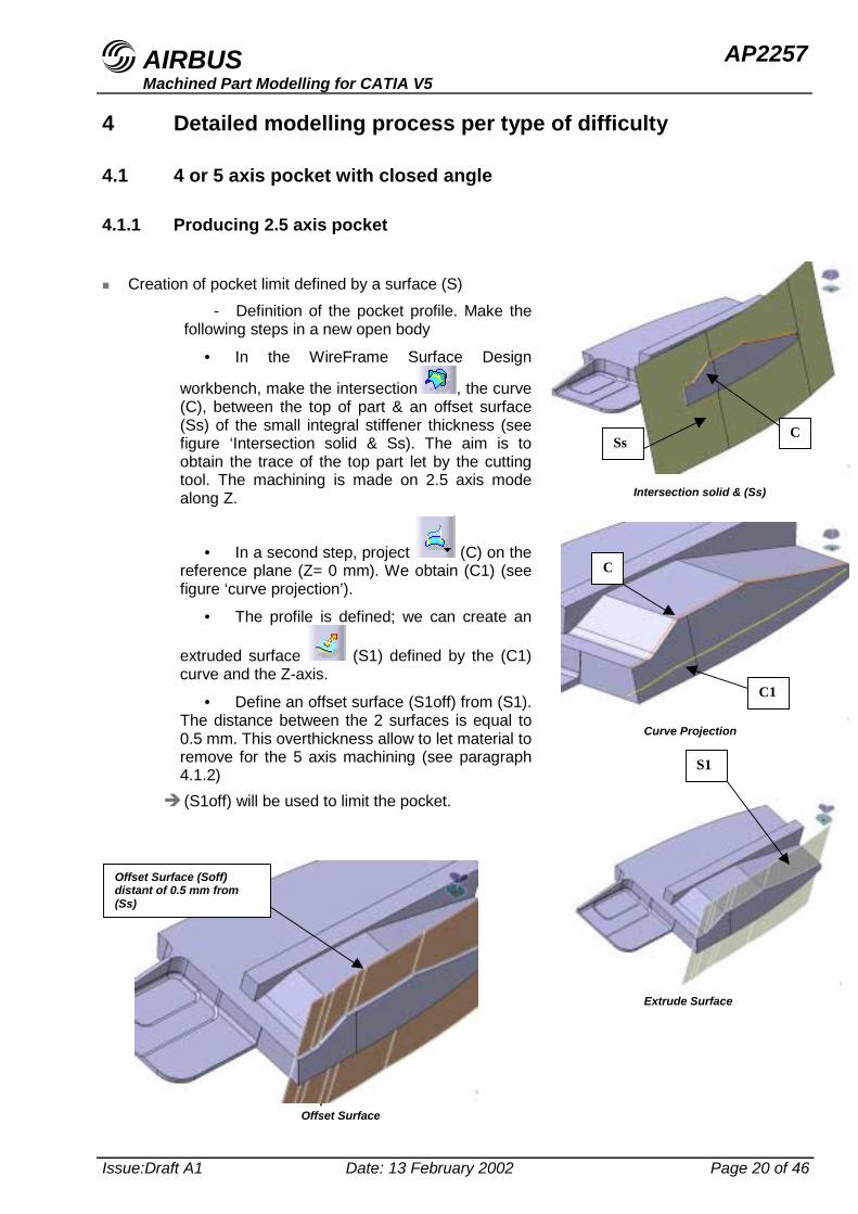
" Creation of pocket limit defined by a surface (S)- Definition of the pocket profile. Make the
following steps in a new open body
• In the WireFrame Surface Design
workbench, make the intersection , the curve(C), between the top of part & an offset surface(Ss) of the small integral stiffener thickness (seefigure ‘Intersection solid & Ss). The aim is toobtain the trace of the top part let by the cuttingtool. The machining is made on 2.5 axis modealong Z.
• In a second step, project (C) on thereference plane (Z= 0 mm). We obtain (C1) (seefigure ‘curve projection’).
• The profile is defined; we can create an
extruded surface (S1) defined by the (C1)curve and the Z-axis.
• Define an offset surface (S1off) from (S1).The distance between the 2 surfaces is equal to0.5 mm. This overthickness allow to let material toremove for the 5 axis machining (see paragraph4.1.2)
# (S1off) will be used to limit the pocket.
- Definition of the pocket contour
C
Intersection solid & (Ss)
Ss
C
C1
Curve Projection
S1
Extrude Surface
Offset Surface
Offset Surface (Soff)distant of 0.5 mm from(Ss)
AIRBUS AP2257Machined Part Modelling for CATIA V5
Issue:Draft A1 Date: 13 February 2002 Page 21 of 46
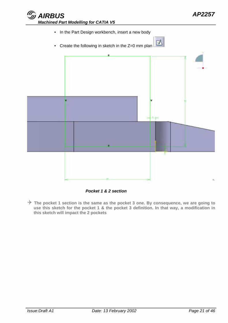
• In the Part Design workbench, insert a new body
• Create the following in sketch in the Z=0 mm plan
! The pocket 1 section is the same as the pocket 3 one. By consequence, we are going touse this sketch for the pocket 1 & the pocket 3 definition. In that way, a modification inthis sketch will impact the 2 pockets
Pocket 1 & 2 section
AIRBUS AP2257Machined Part Modelling for CATIA V5
Issue:Draft A1 Date: 13 February 2002 Page 22 of 46
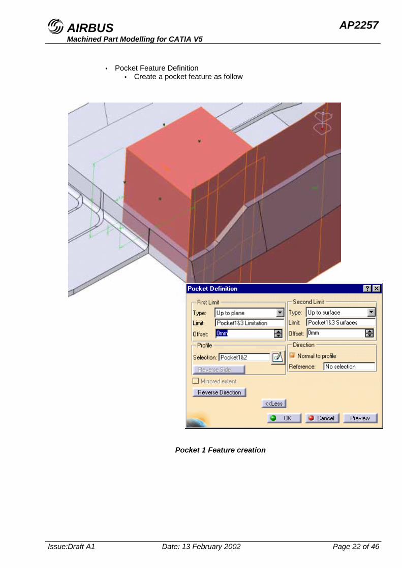
• Pocket Feature Definition• Create a pocket feature as follow
Pocket 1 Feature creation
AIRBUS AP2257Machined Part Modelling for CATIA V5
Issue:Draft A1 Date: 13 February 2002 Page 23 of 46
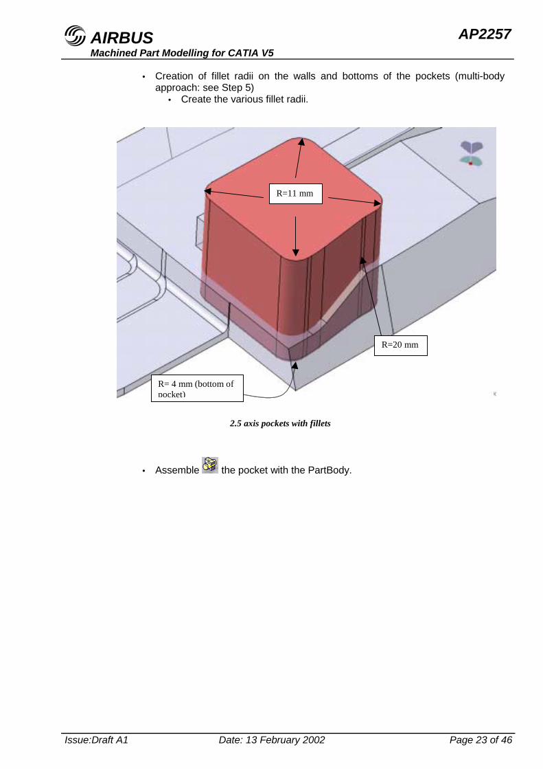
• Creation of fillet radii on the walls and bottoms of the pockets (multi-bodyapproach: see Step 5)
• Create the various fillet radii.
• Assemble the pocket with the PartBody.
R=11 mm
R= 4 mm (bottom ofpocket)
2.5 axis pockets with fillets
R=20 mm
AIRBUS AP2257Machined Part Modelling for CATIA V5
Issue:Draft A1 Date: 13 February 2002 Page 24 of 46
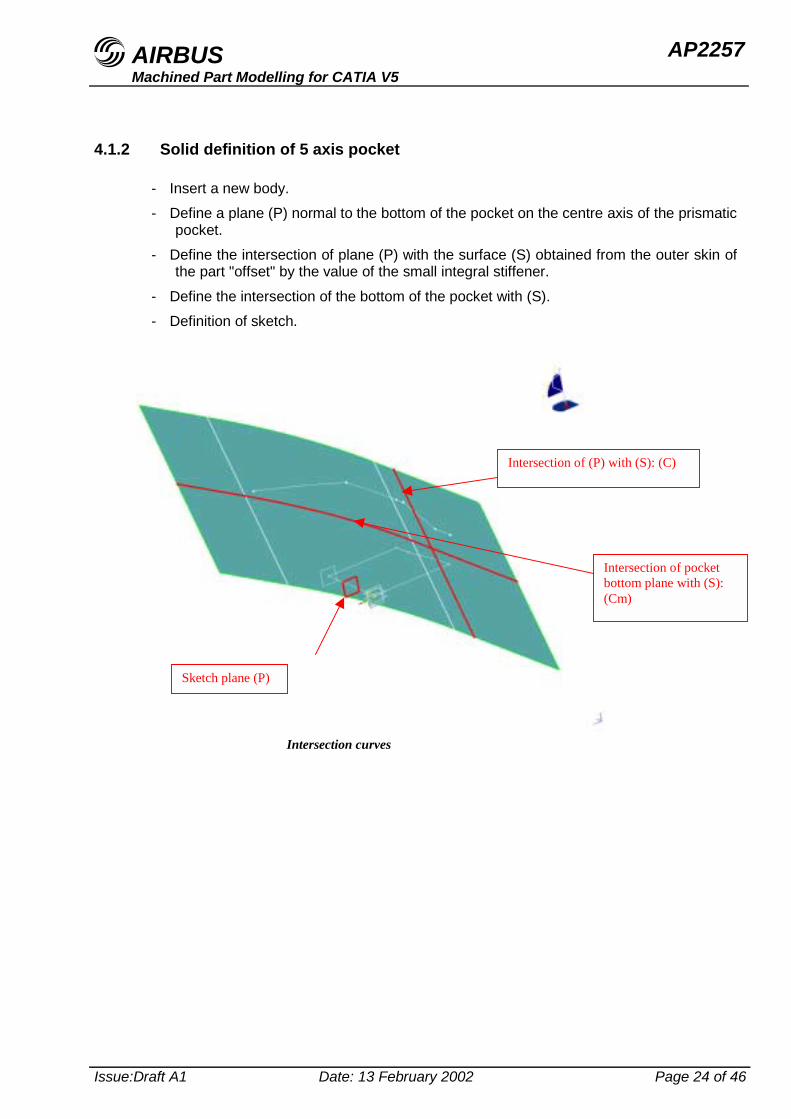
4.1.2 Solid definition of 5 axis pocket
- Insert a new body.- Define a plane (P) normal to the bottom of the pocket on the centre axis of the prismatic
pocket.- Define the intersection of plane (P) with the surface (S) obtained from the outer skin of
the part "offset" by the value of the small integral stiffener.- Define the intersection of the bottom of the pocket with (S).- Definition of sketch.
Intersection of pocketbottom plane with (S):(Cm)
Sketch plane (P)
Intersection of (P) with (S): (C)
Intersection curves
AIRBUS AP2257Machined Part Modelling for CATIA V5
Issue:Draft A1 Date: 13 February 2002 Page 25 of 46
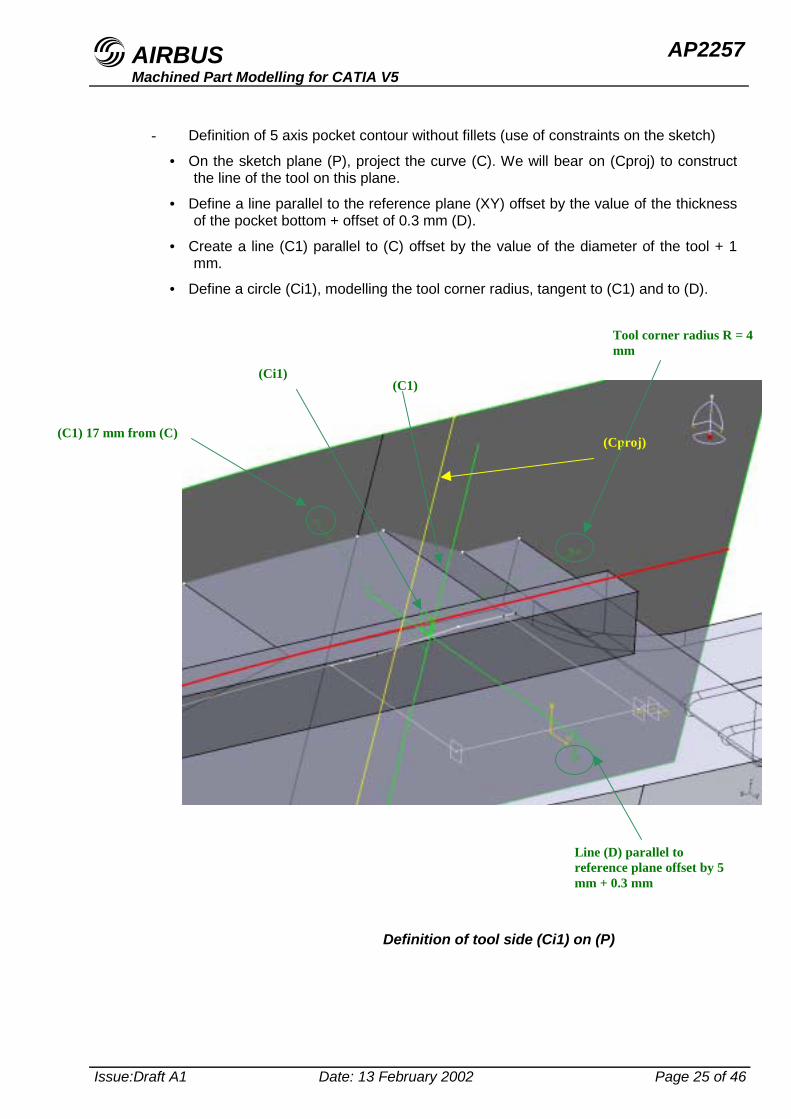
- Definition of 5 axis pocket contour without fillets (use of constraints on the sketch)
• On the sketch plane (P), project the curve (C). We will bear on (Cproj) to constructthe line of the tool on this plane.
• Define a line parallel to the reference plane (XY) offset by the value of the thicknessof the pocket bottom + offset of 0.3 mm (D).
• Create a line (C1) parallel to (C) offset by the value of the diameter of the tool + 1mm.
• Define a circle (Ci1), modelling the tool corner radius, tangent to (C1) and to (D).
(Ci1)
(Cproj)(C1) 17 mm from (C)
Definition of tool side (Ci1) on (P)
Tool corner radius R = 4mm
Line (D) parallel toreference plane offset by 5mm + 0.3 mm
(C1)
AIRBUS AP2257Machined Part Modelling for CATIA V5
Issue:Draft A1 Date: 13 February 2002 Page 26 of 46
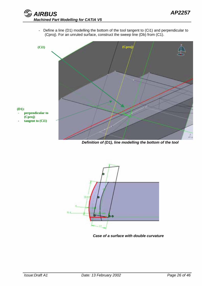
- Define a line (D1) modelling the bottom of the tool tangent to (Ci1) and perpendicular to(Cproj). For an unruled surface, construct the sweep line (Db) from (C1).
Definition of (D1), line modelling the bottom of the tool
(D1):- perpendicular to
(Cproj)- tangent to (Ci1)
(Cproj)(Ci1)
Case of a surface with double curvature
AIRBUS AP2257Machined Part Modelling for CATIA V5
Issue:Draft A1 Date: 13 February 2002 Page 27 of 46
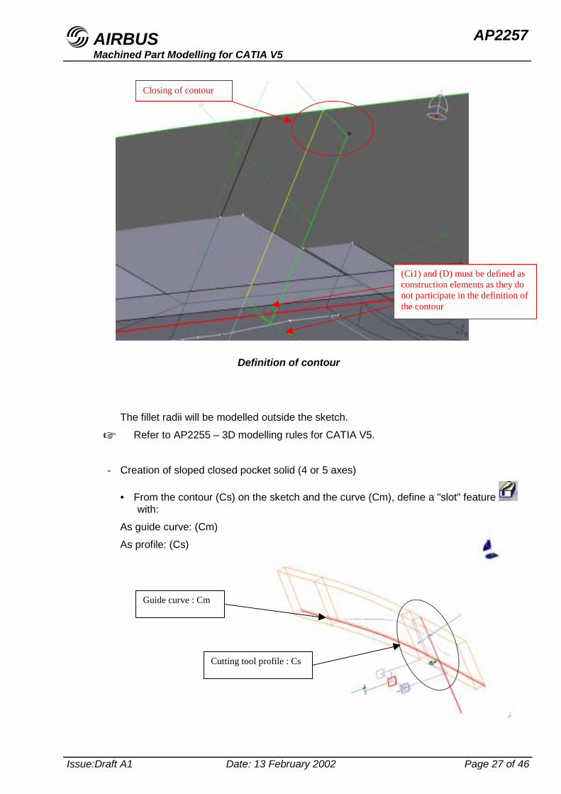
The fillet radii will be modelled outside the sketch.☞ Refer to AP2255 – 3D modelling rules for CATIA V5.
- Creation of sloped closed pocket solid (4 or 5 axes)
• From the contour (Cs) on the sketch and the curve (Cm), define a "slot" feature with:
As guide curve: (Cm)As profile: (Cs)
Definition of contour
Closing of contour
(Ci1) and (D) must be defined asconstruction elements as they donot participate in the definition ofthe contour
Cutting tool profile : Cs
Guide curve : Cm
AIRBUS AP2257Machined Part Modelling for CATIA V5
Issue:Draft A1 Date: 13 February 2002 Page 28 of 46
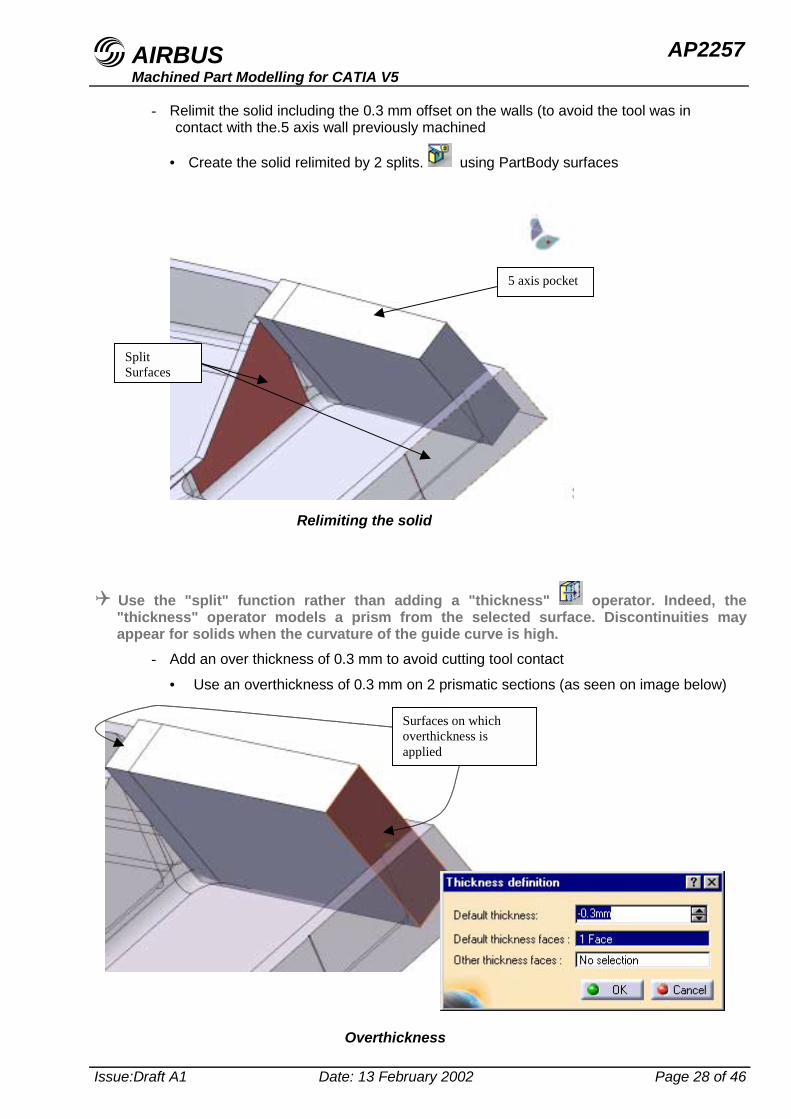
- Relimit the solid including the 0.3 mm offset on the walls (to avoid the tool was incontact with the.5 axis wall previously machined
• Create the solid relimited by 2 splits. using PartBody surfaces
! Use the "split" function rather than adding a "thickness" operator. Indeed, the"thickness" operator models a prism from the selected surface. Discontinuities mayappear for solids when the curvature of the guide curve is high.
- Add an over thickness of 0.3 mm to avoid cutting tool contact
• Use an overthickness of 0.3 mm on 2 prismatic sections (as seen on image below)
Relimiting the solid
SplitSurfaces
5 axis pocket
Overthickness
Surfaces on whichoverthickness isapplied
AIRBUS AP2257Machined Part Modelling for CATIA V5
Issue:Draft A1 Date: 13 February 2002 Page 29 of 46
- Insertion of fillet radii in multi-body approach
• To the body in progress, add fillet radii:
1- For the walls (8.5 mm radius).2- For the pocket bottoms (4 mm radius).
- Assemble this new pocket with the PartBody
4.2 4 or 5 axis pocket with open angle
4.2.1 Producing 2.5 axis pocket
- Definition of section construction plane
! For correct distribution of the data, create a new "OpenBody" with a specific name inwhich we will find all of the construction data used for the construction of the 2.5 axis and5 axis pockets. Indeed, these elements do not directly participate in the definition of thepocket contours. They must therefore not appear in the sketch associated with the "body"defining the latter.
• Construct the "offset" surface (S1) from the outer surface of the part offset bythe value of the small integral stiffener thickness.
• Define the pocket thickness plane intersection curve (C2) with the small integralstiffener inner surface (S1).
• Construct a plane (P1) normal to the inner line of the contour passing through itscentre. Use here the plane (P) previously used to define the 5 axis pocket.
• Define the intersection curve between (P1) and (S1) called (C3).
• Construct on plane (P1) the sketch containing the construction elements used todetermine the contour of the 2.5 axis pocket.
AIRBUS AP2257Machined Part Modelling for CATIA V5
Issue:Draft A1 Date: 13 February 2002 Page 30 of 46
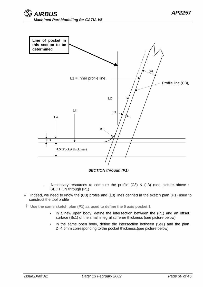
- Necessary resources to compute the profile (C3) & (L3) (see picture above :‘SECTION through (P1)
" Indeed, we need to know the (C3) profile and (L3) lines defined in the sketch plan (P1) used toconstruct the tool profile
! Use the same sketch plan (P1) as used to define the 5 axis pocket 1• In a new open body, define the intersection between the (P1) and an offset
surface (Ss1) of the small integral stiffener thickness (see picture below)
• In the same open body, define the intersection between (Ss1) and the planZ=4.5mm corresponding to the pocket thickness.(see picture below)
Profile line (C3),
(4)
L1 = Inner profile line
L2
4.5 (Pocket thickness)
0.3
0.3
R1
L3
L4
Line of pocket inthis section to bedetermined
SECTION through (P1)
AIRBUS AP2257Machined Part Modelling for CATIA V5
Issue:Draft A1 Date: 13 February 2002 Page 31 of 46
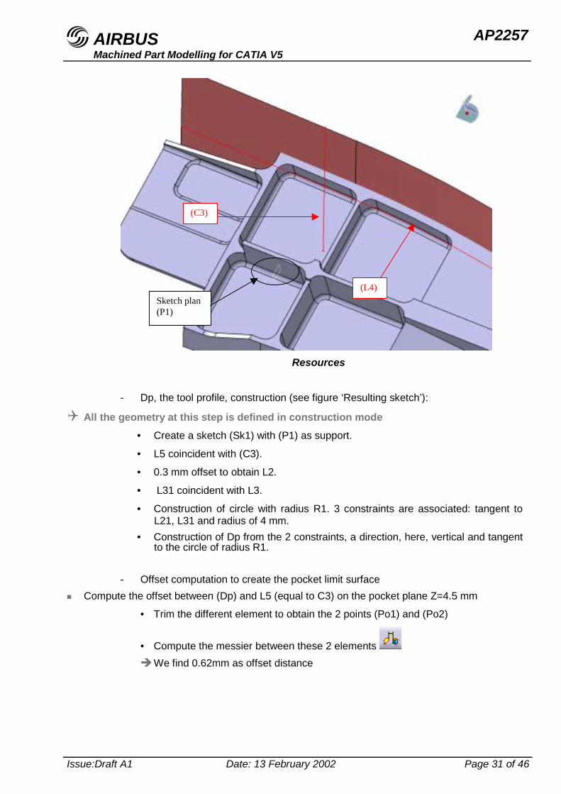
- Dp, the tool profile, construction (see figure ‘Resulting sketch’):
! All the geometry at this step is defined in construction mode• Create a sketch (Sk1) with (P1) as support.
• L5 coincident with (C3).
• 0.3 mm offset to obtain L2.
• L31 coincident with L3.
• Construction of circle with radius R1. 3 constraints are associated: tangent toL21, L31 and radius of 4 mm.
• Construction of Dp from the 2 constraints, a direction, here, vertical and tangentto the circle of radius R1.
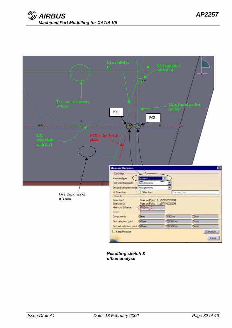
- Offset computation to create the pocket limit surface" Compute the offset between (Dp) and L5 (equal to C3) on the pocket plane Z=4.5 mm
• Trim the different element to obtain the 2 points (Po1) and (Po2)
• Compute the messier between these 2 elements # We find 0.62mm as offset distance
Resources
Sketch plan(P1)
(C3)
(L4)
AIRBUS AP2257Machined Part Modelling for CATIA V5
Issue:Draft A1 Date: 13 February 2002 Page 32 of 46
Tool corner diameter,D=8mm
L31coincidentwith (L3)
L5 coincidentwith (C3)
Line, Dp, of pocketprofile
Resulting sketch &offset analyse
Overthickness of0.3 mm
(C3)in the sketchplane
L2 parallel toL5
P01P02
AIRBUS AP2257Machined Part Modelling for CATIA V5
Issue:Draft A1 Date: 13 February 2002 Page 33 of 46
- Definition of pocket limit surface" Once you know the offset value, we can construct in the same open body, the corresponding
offset curve in the WireFrame workbench
• Define the offset surface (Ss1’) from (Ss1) distant from the offset value (here,
0.62 mm)
• Compute the intersection between (Ss1’) and the pocket plane Z=4.5 mm
• Construct the extrude surface (Sl) defined by this intersection & Z axis (Zcorresponding to the machining axis)
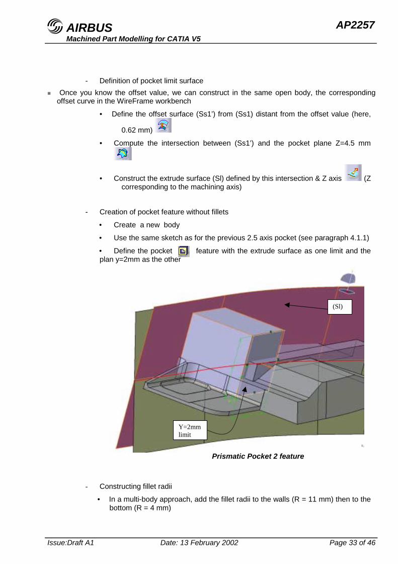
- Creation of pocket feature without fillets
• Create a new body
• Use the same sketch as for the previous 2.5 axis pocket (see paragraph 4.1.1)
• Define the pocket feature with the extrude surface as one limit and theplan y=2mm as the other
- Constructing fillet radii
• In a multi-body approach, add the fillet radii to the walls (R = 11 mm) then to thebottom (R = 4 mm)
(Sl)
Y=2mmlimit
Prismatic Pocket 2 feature
AIRBUS AP2257Machined Part Modelling for CATIA V5
Issue:Draft A1 Date: 13 February 2002 Page 34 of 46
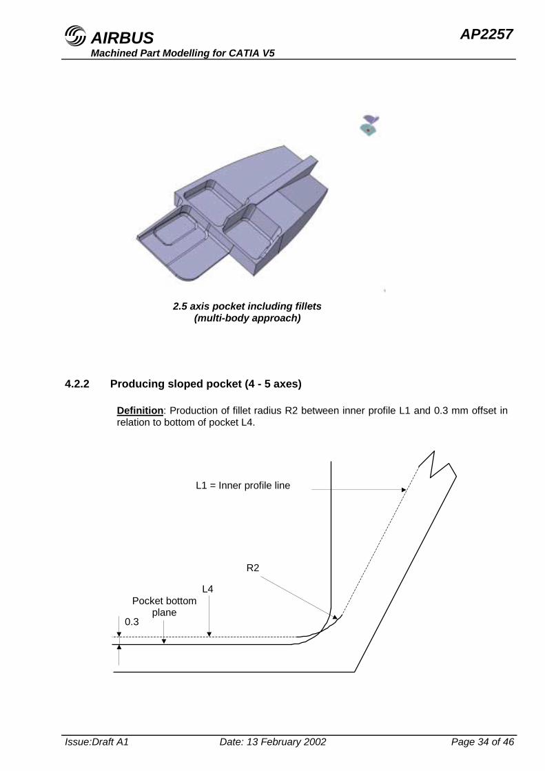
4.2.2 Producing sloped pocket (4 - 5 axes)
Definition: Production of fillet radius R2 between inner profile L1 and 0.3 mm offset inrelation to bottom of pocket L4.
L1 = Inner profile line
Pocket bottomplane
0.3
L4
R2
2.5 axis pocket including fillets(multi-body approach)
AIRBUS AP2257Machined Part Modelling for CATIA V5
Issue:Draft A1 Date: 13 February 2002 Page 35 of 46
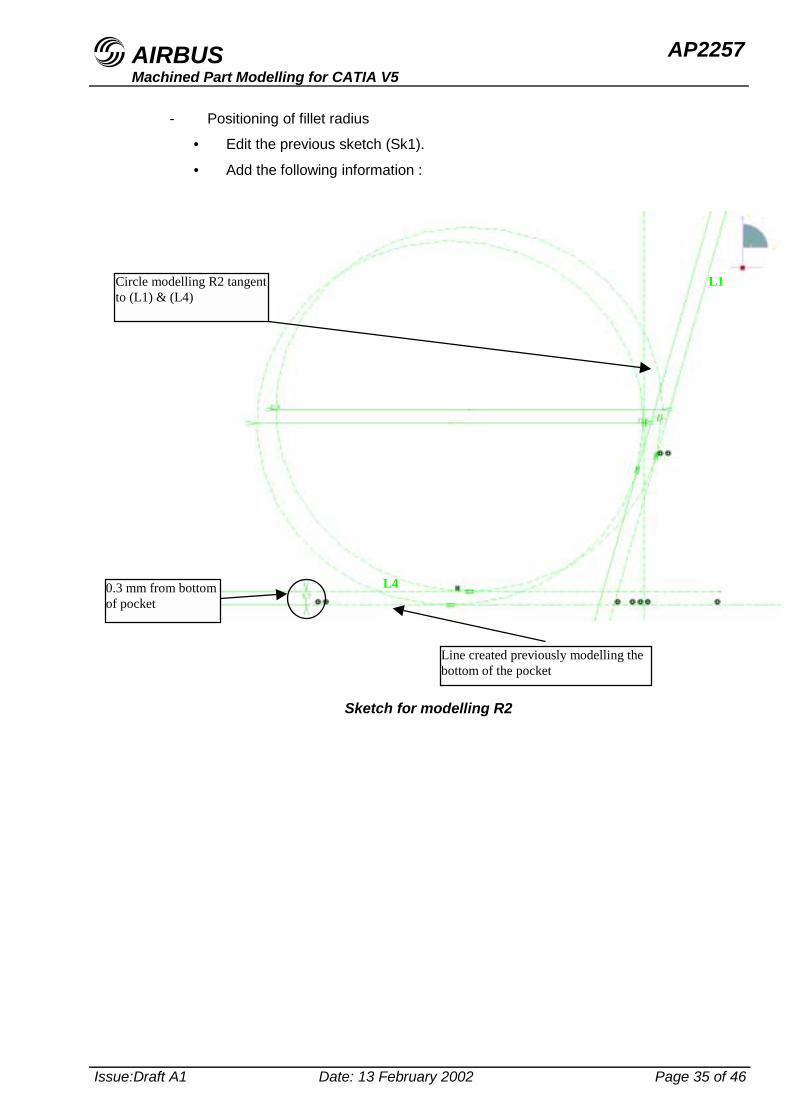
- Positioning of fillet radius
• Edit the previous sketch (Sk1).
• Add the following information :
Line created previously modelling thebottom of the pocket
0.3 mm from bottomof pocket
L4
Circle modelling R2 tangentto (L1) & (L4)
L1
Sketch for modelling R2
AIRBUS AP2257Machined Part Modelling for CATIA V5
Issue:Draft A1 Date: 13 February 2002 Page 36 of 46
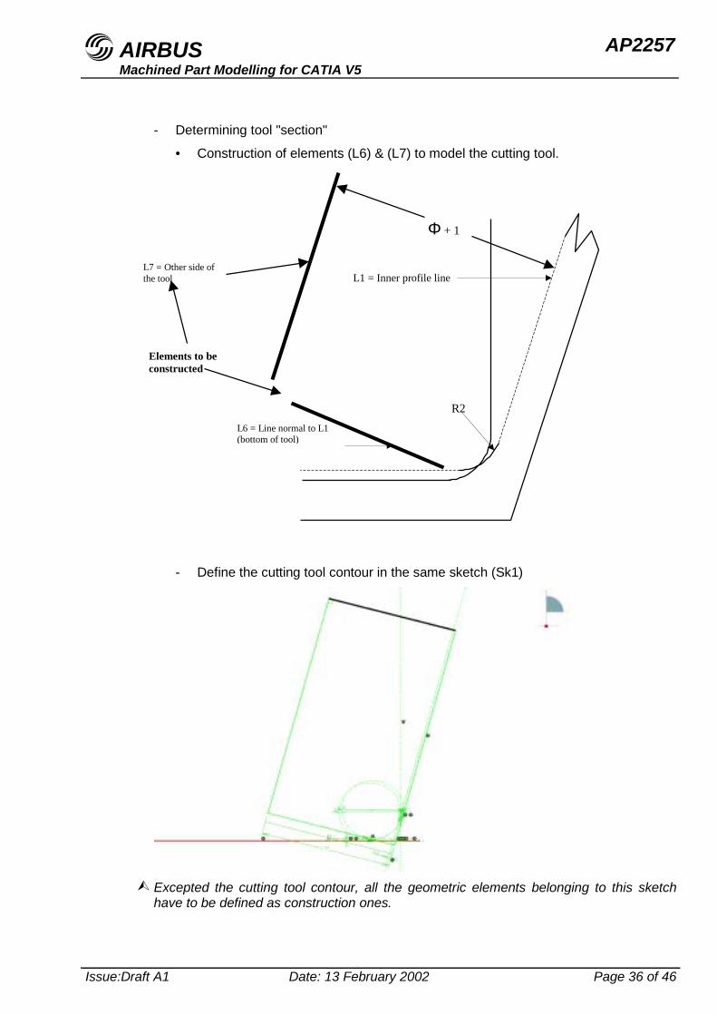
- Determining tool "section"
• Construction of elements (L6) & (L7) to model the cutting tool.
- Define the cutting tool contour in the same sketch (Sk1)
$ Excepted the cutting tool contour, all the geometric elements belonging to this sketchhave to be defined as construction ones.
L1 = Inner profile line
L6 = Line normal to L1(bottom of tool)
R2
L7 = Other side ofthe tool
Φ + 1
Elements to beconstructed
AIRBUS AP2257Machined Part Modelling for CATIA V5
Issue:Draft A1 Date: 13 February 2002 Page 37 of 46
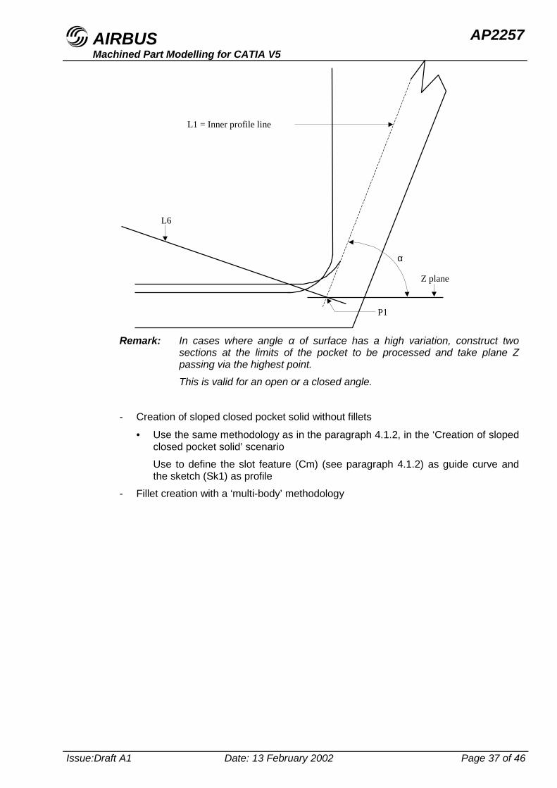
Remark: In cases where angle α of surface has a high variation, construct twosections at the limits of the pocket to be processed and take plane Zpassing via the highest point.This is valid for an open or a closed angle.
- Creation of sloped closed pocket solid without fillets
• Use the same methodology as in the paragraph 4.1.2, in the ‘Creation of slopedclosed pocket solid’ scenarioUse to define the slot feature (Cm) (see paragraph 4.1.2) as guide curve andthe sketch (Sk1) as profile
- Fillet creation with a ‘multi-body’ methodology
L6
Z plane
P1
α
L1 = Inner profile line
AIRBUS AP2257Machined Part Modelling for CATIA V5
Issue:Draft A1 Date: 13 February 2002 Page 38 of 46
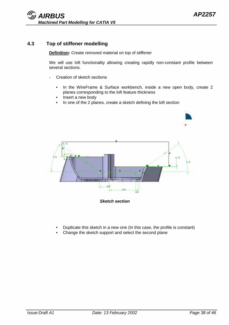
4.3 Top of stiffener modellingDefinition: Create removed material on top of stiffener
We will use loft functionality allowing creating rapidly non-constant profile betweenseveral sections.
- Creation of sketch sections
• In the WireFrame & Surface workbench, inside a new open body, create 2planes corresponding to the loft feature thickness
• Insert a new body• In one of the 2 planes, create a sketch defining the loft section
• Duplicate this sketch in a new one (In this case, the profile is constant)• Change the sketch support and select the second plane
Sketch section
AIRBUS AP2257Machined Part Modelling for CATIA V5
Issue:Draft A1 Date: 13 February 2002 Page 39 of 46
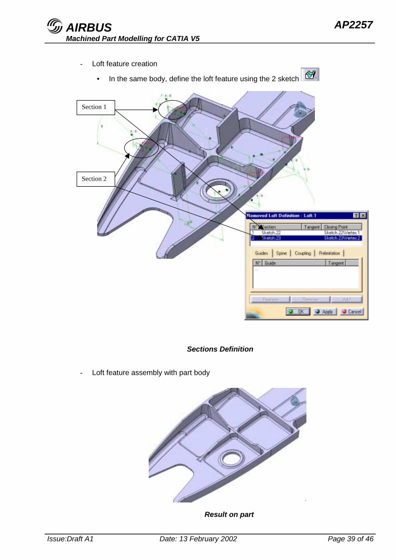
- Loft feature creation
• In the same body, define the loft feature using the 2 sketch
- Loft feature assembly with part body
Sections Definition
Section 1
Section 2
Result on part
AIRBUS AP2257Machined Part Modelling for CATIA V5
Issue:Draft A1 Date: 13 February 2002 Page 40 of 46
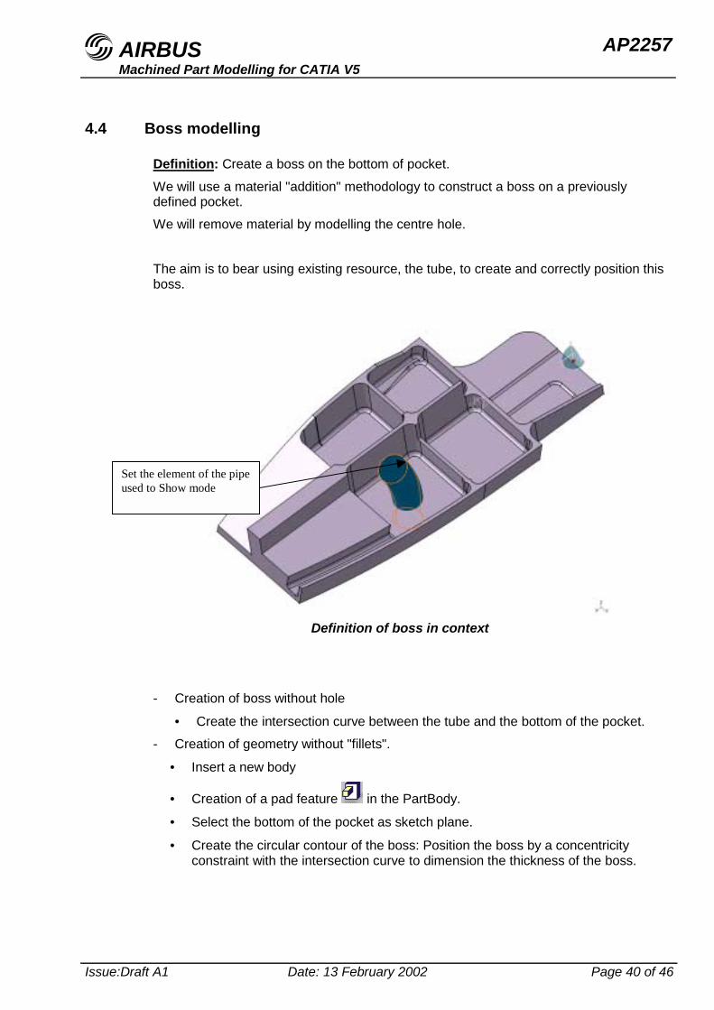
4.4 Boss modelling
Definition: Create a boss on the bottom of pocket.
We will use a material "addition" methodology to construct a boss on a previouslydefined pocket.We will remove material by modelling the centre hole.
The aim is to bear using existing resource, the tube, to create and correctly position thisboss.
- Creation of boss without hole
• Create the intersection curve between the tube and the bottom of the pocket.- Creation of geometry without "fillets".
• Insert a new body
• Creation of a pad feature in the PartBody.
• Select the bottom of the pocket as sketch plane.
• Create the circular contour of the boss: Position the boss by a concentricityconstraint with the intersection curve to dimension the thickness of the boss.
Definition of boss in context
Set the element of the pipeused to Show mode
AIRBUS AP2257Machined Part Modelling for CATIA V5
Issue:Draft A1 Date: 13 February 2002 Page 41 of 46
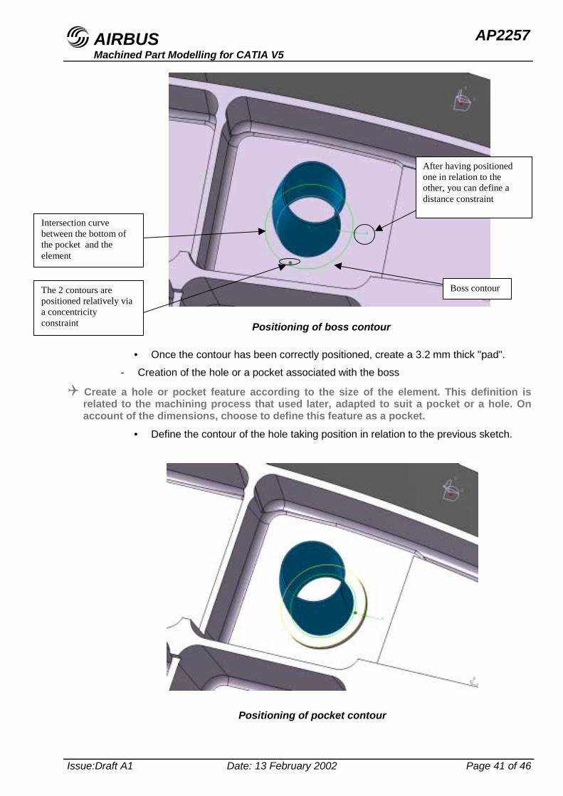
• Once the contour has been correctly positioned, create a 3.2 mm thick "pad".
- Creation of the hole or a pocket associated with the boss
! Create a hole or pocket feature according to the size of the element. This definition isrelated to the machining process that used later, adapted to suit a pocket or a hole. Onaccount of the dimensions, choose to define this feature as a pocket.
• Define the contour of the hole taking position in relation to the previous sketch.
Positioning of boss contour
Positioning of pocket contour
Intersection curvebetween the bottom ofthe pocket and theelement
The 2 contours arepositioned relatively viaa concentricityconstraint
Boss contour
After having positionedone in relation to theother, you can define adistance constraint
AIRBUS AP2257Machined Part Modelling for CATIA V5
Issue:Draft A1 Date: 13 February 2002 Page 42 of 46
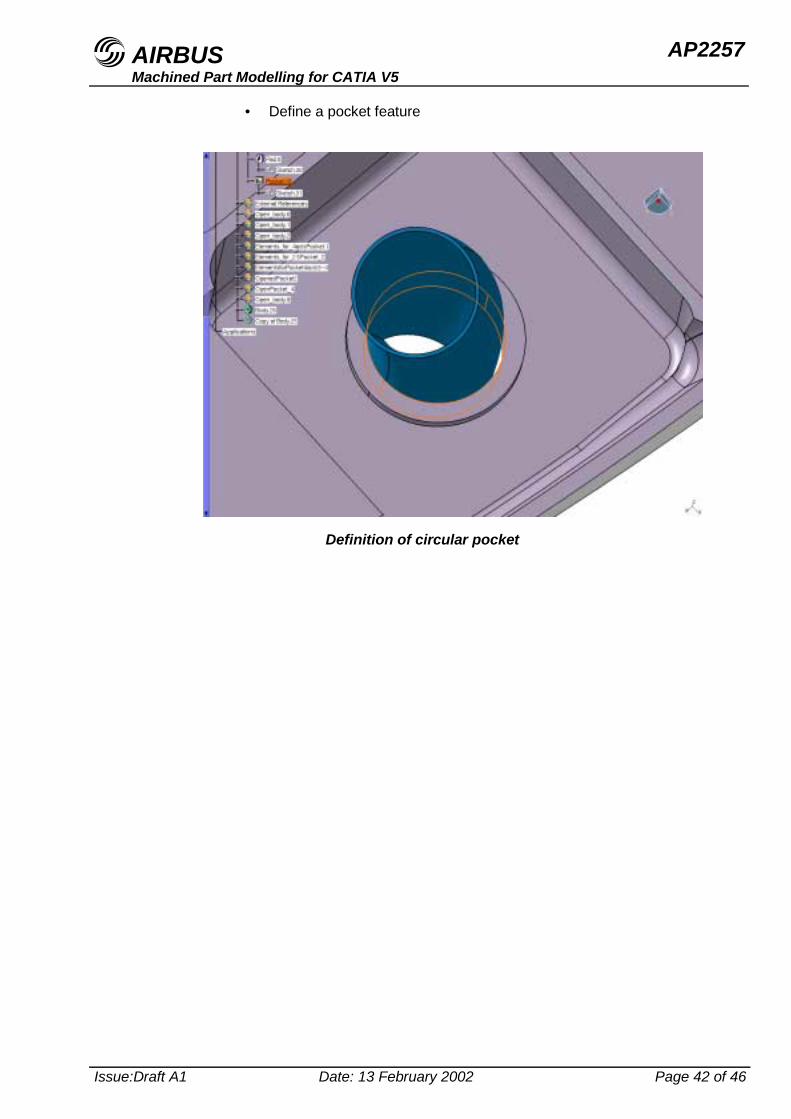
• Define a pocket feature
Definition of circular pocket
AIRBUS AP2257Machined Part Modelling for CATIA V5
Issue:Draft A1 Date: 13 February 2002 Page 43 of 46
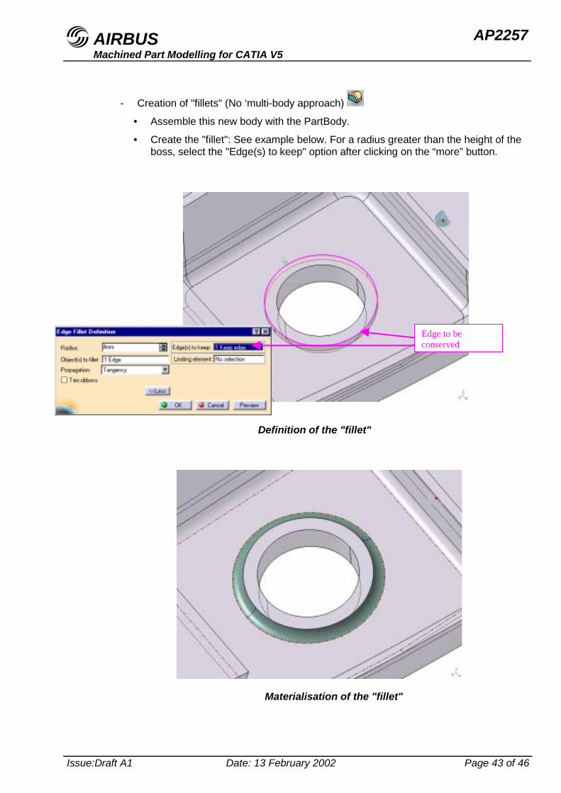
- Creation of "fillets" (No ‘multi-body approach)
• Assemble this new body with the PartBody.
• Create the "fillet": See example below. For a radius greater than the height of theboss, select the "Edge(s) to keep" option after clicking on the “more” button.
93 27 44
Definition of the "fillet"
Materialisation of the "fillet"
Edge to beconserved
AIRBUS AP2257Machined Part Modelling for CATIA V5
Issue:Draft A1 Date: 13 February 2002 Page 44 of 46
5 Identifying modifications
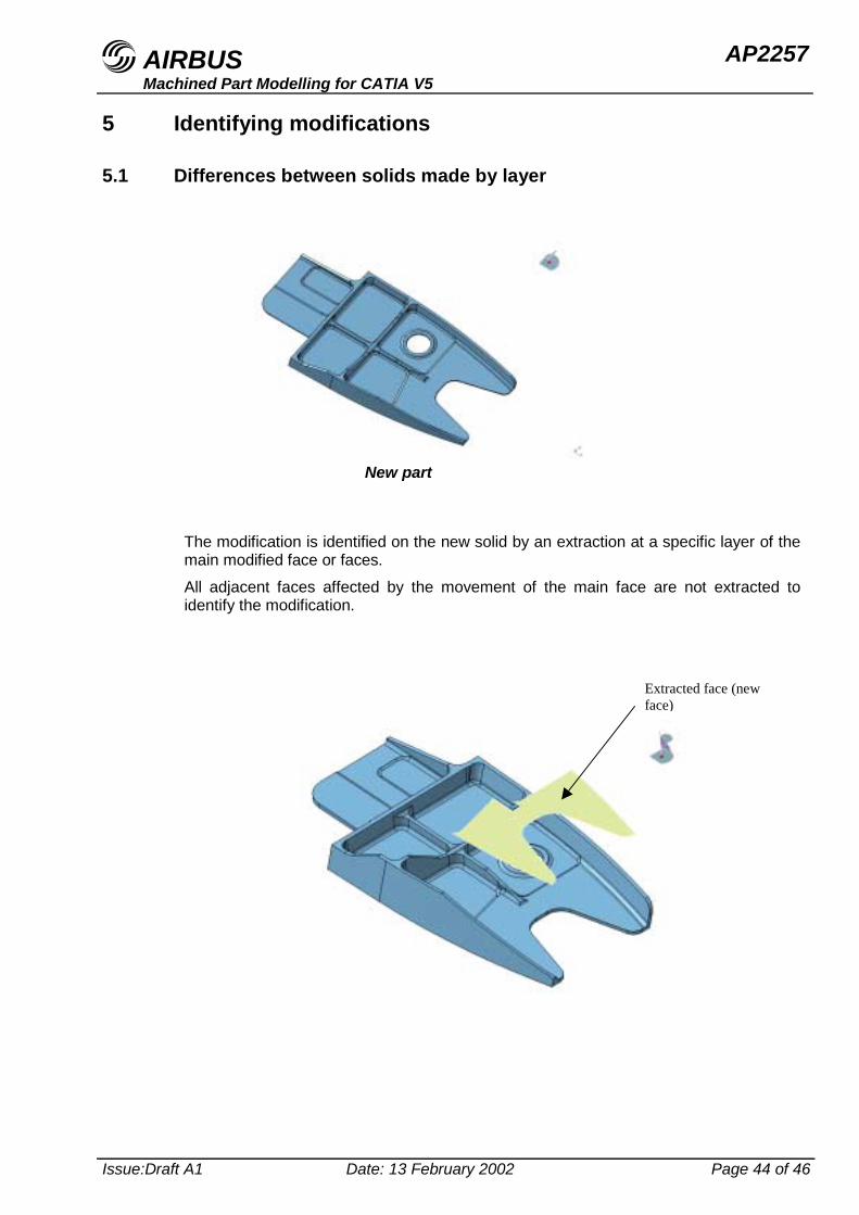
5.1 Differences between solids made by layer
The modification is identified on the new solid by an extraction at a specific layer of themain modified face or faces.All adjacent faces affected by the movement of the main face are not extracted toidentify the modification.
New part
Extracted face (newface)
AIRBUS AP2257Machined Part Modelling for CATIA V5
Issue:Draft A1 Date: 13 February 2002 Page 45 of 46
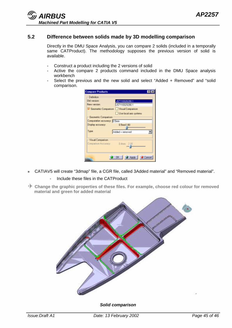
5.2 Difference between solids made by 3D modelling comparisonDirectly in the DMU Space Analysis, you can compare 2 solids (included in a temporallysame CATProduct). The methodology supposes the previous version of solid isavailable.
- Construct a product including the 2 versions of solid- Active the compare 2 products command included in the DMU Space analysis
workbench- Select the previous and the new solid and select “Added + Removed” and “solid
comparison.
" CATIAV5 will create “3dmap” file, a CGR file, called 3Added material” and “Removed material”.- Include these files in the CATProduct
! Change the graphic properties of these files. For example, choose red colour for removedmaterial and green for added material
Solid comparison
AIRBUS AP2257Machined Part Modelling for CATIA V5
Issue:Draft A1 Date: 13 February 2002 Page 46 of 46
Reference documents
AP 2622 CAD layers organisationAP 2610 Naming and Numbering for New ProjectsAP 2260 Drawing rules for CATIA V5AP 2255 3D Modelling rules for CATIA V5ABD 0004 Definition dossier
Group of redaction
Team Members Company / Department TelephoneCANO-RODRIGUEZ Pedro Airbus España +34 916241292Gilles MERCADIER EMK-T +33 561184933
Approval
This document has been approved on behalf of the following:(signatures or proof of agreement are archived together with the master document)
Organization ApprovalACE/SPD/Elementary parts/Mechanical Parts Generic C .Vergez - OIMM1
CoC Structure H Schnell - ESDSEM Quality Assurance
representative Nicole Lamothe - EMZQ
Record of revisions
Issue Date Summary and reasons for changesDraft A1 February 2002 Initial issue
If you have a query concerning the implementation or updating of this document, pleasecontact the Owner on page 1
Or a team member of the group of redactionFor general queries or information contact:
Airbus Documentation Office,Airbus
31707 Blagnac CEDEX,France
Tel: 33 (0)5 61 93 49 93 Fax: 33 (0)5 61 93 27 44