machine vision peripheral equipment & effective image ... · pdf filemachine vision...
TRANSCRIPT

Machine Vision Peripheral Equipment & Effective Image Acquisition TechniquesPeripheral Equipments for Machine Vis ion Solut ion
Vision System Peripheral EquipmentCA Series
NEW

02
Maximising vision system performance
Effective use of peripheral equipment can ensure the success of using machine vision for solving an application.
High quality lensing for sharp images over a wide range of working distances. Maximising the resolution of the camera to inspect targets.
Correct lighting for consistent target illumination and feature highlighting.
Correct lighting colour to maximise contrast and ensure reliable inspection.
Filters to reduce lighting anomalies.

03
C O N T E N T S
LED Light Lineup LED Light Controllers
Lens Lineup
Monitors, Power Supply
CA-M/CA-U Series���������������������������������������������������� P� 54Monitors/Power Supplies
CA-DR-M/CA-DQ-M Series��������������������������������������������������������� P� 06Multi-angle Lights (Ring/Square)
CA-DR Series��������������������������������������������������������� P� 04Ring Lights (Direct)
CA-LHE Series��������������������������������������������������������� P� 32Ultra High Resolution, Low Distortion Lens Supporting 4/3" Images
CA-LHR Series��������������������������������������������������������� P� 34High Resolution, Low Distortion Lens
CA-LH/CA-LH×G Series��������������������������������������������������������� P� 36Low Distortion Lens
CV-L Series��������������������������������������������������������� P� 39Standard Lens
CA-LHW/CA-LHL/CA-LM Series��������������������������������������������������������� P� 40High-resolution Lenses for Line Scan Cameras
CA-LMHR Series��������������������������������������������������������� P� 42Distortion-free, VPR-equipped, Telecentric Macro Lens
CA-LMHE Series��������������������������������������������������������� P� 44Variable-magnification Telecentric Macro Lens Supporting 4/3" Images
CA-LS/CA-LHS Series��������������������������������������������������������� P� 47Super Small Camera Dedicated Lens
CA-LM Series��������������������������������������������������������� P� 45Variable-magnification Telecentric Macro Lens Supporting 2/3" Images/Telecentric Macro Lens
CA-DRWxX Series��������������������������������������������������������� P� 08LumiTrax Lights
CA-DB Series��������������������������������������������������������� P� 10Bar Lights
CA-DD Series��������������������������������������������������������� P� 12Dome Lights
CA-DS Series��������������������������������������������������������� P� 14Back Lights
CA-DX Series��������������������������������������������������������� P� 18Coaxial Lights (Vertical)
CA-DWC Series��������������������������������������������������������� P� 16Wavelength Conversion Sheet
CA-DP Series��������������������������������������������������������� P� 20Spot Lights
CA-DL Series��������������������������������������������������������� P� 22Low Angle Lights
CA-DQ Series��������������������������������������������������������� P� 23Square Lights (Direct)
CA-DZ Series��������������������������������������������������������� P� 24Line Lights
CA-DC Series��������������������������������������������������������� P� 26Illumination Controller
NEW NEW
NEW
NEW
NEW
NEW

Light features and settings
Ring light illumination techniques
Application
04
Concentrically arranged LED’s provide uniform lighting suitable for standard targets & applications.
Six types of lights are available, including those with and without diffusion plates and polarisation plates� This enables the selection of the right light to match the workpiece�
Ring light only Ring light + polarising filter
Flat type
Camera
Target
Light is reflected circumferentially according to the target profile� The target surface condition can be clearly seen�
You can obtain an image without halation by using the polarising plate�
Plastic bottle
Camera/light arrangement
CA-DR Series
Ring Lights (Direct)General-purpose ring illumination unit
The CA-DR Series includes flat horizontally arranged LEDs, which help provide uniform intensity across a target� Six different sizes and colours of light with optional diffuse and polarising filters are available� Making the ring well suited to a wide variety of application and camera needs�

Lineup
Optional parts
Ring light (direct) intensity distribution (typical)
05
CA-DRx 3
CA-DRx 7
CA-DRx 4F
CA-DRx9/10F
CA-DRx 5
CA-DRx 9
CA-DRx 10F
16.5
4 x M3, d=5 ø38ø28ø15
L=500
3 x M1.6, d=3
17
L=5004 x M3, d=6
ø50
ø28ø40
3 x M1.6, d=3
L=5004 x M3, d=6
3 x M1.6, d=3
18
20.5
4 x M3, d=6
3 x M1.6, d=3
L=500
20
4 x M3, d=5
3 x M1.6, d=3
L=500
20 L=500
3 x M1.6, d=3
4 x M3, d=5
14.8
21.2
30 78
20.5
45.5 4095.5
Long hole for camera mounting
16.6
69 70
2 x M3, d=6
ø70ø50ø39 ø90
ø70ø50
ø43ø28ø15
ø100ø70ø50
Part number Applicable light
OP-42337 CA-DRx4F
OP-42339 CA-DRx10F
Part number Applicable light
OP-42336 CR-DRx4F
OP-42338 CR-DRx10F
Part number(Flat type)
LED colour Weight Power
consumptionInput
voltage
CA-DRR4F Approx. 20 g 1.5 W
12 V
CA-DRW4F Approx. 20 g 2.9 W
CA-DRB4F Approx. 20 g 2.9 W
CA-DRR10F Approx. 90 g 8.3 W
CA-DRW10F Approx. 80 g 7.9 W
CA-DRB10F Approx. 80 g 7.9 W
Diffusion plate
LED imprint preventionThe diffusion plate eliminates reflection of LEDs and irregular lighting conditions that may occur in capturing an image of a glossy target�
Polarising plate
Glare preventionEliminate the glare on glossy targets when combined with a lens polarising filter�
CA-DRx 3
CA-DRx 7
CA-DRx 4F
CA-DRx9/10F
CA-DRx 5
CA-DRx 9
CA-DRx 10F
16.5
4 x M3, d=5 ø38ø28ø15
L=500
3 x M1.6, d=3
17
L=5004 x M3, d=6
ø50
ø28ø40
3 x M1.6, d=3
L=5004 x M3, d=6
3 x M1.6, d=3
18
20.5
4 x M3, d=6
3 x M1.6, d=3
L=500
20
4 x M3, d=5
3 x M1.6, d=3
L=500
20 L=500
3 x M1.6, d=3
4 x M3, d=5
14.8
21.2
30 78
20.5
45.5 4095.5
Long hole for camera mounting
16.6
69 70
2 x M3, d=6
ø70ø50ø39 ø90
ø70ø50
ø43ø28ø15
ø100ø70ø50
CA-DRx4F
When the mounting bracket is attachedCA-DRx10F
CA-DRx10F
* Mounting brackets cannot be used in combinations of cameras and lenses whose part numbers start with “CA-�” For details, contact KEYENCE�
Thickness: Approx� 2 mm
The above image displays the relative brightness across a 10000 point grid for the CA-DR Series� Although the intensity varies with each model type, the associated illumination distance and relative brightness across the area are consistent�The brightest areas (shown in red) are considered 100% relative intensity and the dullest areas (shown in green) are considered 0% relative intensity� The images display the intensity differential across the area� By comparing the changes in the intensity differential for different lighting heights (LWD) the ideal lighting range can be realised with the relative brightest points being 100%�
* The above data are representative examples� This is not a guarantee of the product quality�* LWD is the distance from the illumination to
the measurement target�
LWD: 50 mm LWD: 80 mm LWD: 110 mm100
0
215 mm
Dimensions Unit: mm
When CA-DRW10F is used:

Light features and settings
Camera/ light arrangement
Application
06
High-density mounting of power LEDs Matte-finished diffusion plate
With standard lighting With standard lightingWith multi-angle light [Ring] With multi-angle light [Square]
Multi-Angle Light
When the LWD is far
When the LWD is close
Camera
Target
LED reflection/imprint is seen by camera�
Due to the differences in solder ball shape and size their appearance is inconsistent�
Multi angle diffused light is radiated around the inner surface to give uniform illumination�
The multi angle diffused light results in consistent illumination of all the solder balls and an overall brighter image�
When the light to target distance is far the multi angled diffused light is applied across the whole of the target� This creates a uniform illumination effect without irregularities similar to using a dome light source�
When the light to target distance is short the light emitted at a shallow angle reflects directly back to the camera� This causes the edges of the target to be highlighted creating an effect similar to using a low angle light source�
Edge enhancement illumination equivalent to low angle lighting
Since LEDs are mounted at high density (narrow pitch), uniform high intensity light is generated�
To obtain maximum diffusion effect, the whole area of the diffusion plate has a matte finish�
LED
Reflective mirror
Aluminium body
Diffusion plate
Inside of a plastic cap BGA/solder ball inspection
LWD: 10 mm
LWD: 150 mm
Ideal on targets with changes in height needing multi angle diffused or low angle lighting.
These are flexible lights that can be used to match the optimal lighting conditions for the workpiece�
CA-DR-M/CA-DQ-M Series
Multi-angle Lights (Ring/Square)Combines the principals of ring, dome and low angle light sources into one
Uniform illumination equivalent to dome lighting

Multi angle light intensity distribution (typical)
Lineup
Dimensions Unit: mm
07
155 mm
240 mm
LWD: 50 mm
LWD: 50 mm
LWD: 70 mm
LWD: 70 mm
LWD: 90 mm
LWD: 90 mm
When CA-DRW8M is used:
When CA-DQW10M is used:
* The data to the left are representative examples� This is not a guarantee of the product quality�
* LWD is the distance from the illumination to the measurement target�
100
0
CA-DRx8M
CA-DRx13M
CA-DQx7M
CA-DQx10M
CA-DQx12M
L=500
26.590 °
4 x M3, d=5
ø36 ø80
ø86 ø130
ø55
ø107
L=500
26.5
4 x M3, d=5
90 °
L=500
76120
76 120
26.54 x M3, d=5
97
97
L=500
56 100
56100
26.54 x M3, d=5
77
77
L=500
2670
26 70
26.54 x M3, d=547
47
CA-DRx8M
CA-DRx13M
CA-DQx7M
CA-DQx10M
CA-DQx12M
L=500
26.590 °
4 x M3, d=5
ø36 ø80
ø86 ø130
ø55
ø107
L=500
26.5
4 x M3, d=5
90 °
L=500
76120
76 120
26.54 x M3, d=5
97
97
L=500
56 100
56100
26.54 x M3, d=5
77
77
L=500
2670
26 70
26.54 x M3, d=547
47
CA-DRx8M
CA-DRx13M
CA-DQx7M
CA-DQx10M
CA-DQx12M
L=500
26.590 °
4 x M3, d=5
ø36 ø80
ø86 ø130
ø55
ø107
L=500
26.5
4 x M3, d=5
90 °
L=500
76120
76 120
26.54 x M3, d=5
97
97
L=500
56 100
56100
26.54 x M3, d=5
77
77
L=500
2670
26 7026.54 x M3, d=547
47
CA-DRx8M
CA-DRx13M
CA-DQx7M
CA-DQx10M
CA-DQx12M
L=500
26.590 °
4 x M3, d=5
ø36 ø80
ø86 ø130
ø55
ø107
L=500
26.5
4 x M3, d=5
90 °
L=500
76120
76 120
26.54 x M3, d=5
97
97
L=500
56 100
56100
26.54 x M3, d=5
77
77
L=500
2670
26 70
26.54 x M3, d=547
47
CA-DRx8M
CA-DRx13M
CA-DQx7M
CA-DQx10M
CA-DQx12M
L=500
26.590 °
4 x M3, d=5
ø36 ø80
ø86 ø130
ø55
ø107
L=500
26.5
4 x M3, d=5
90 °
L=500
76120
76 120
26.54 x M3, d=5
97
97
L=500
56 100
56100
26.54 x M3, d=5
77
77
L=500
2670
26 70
26.54 x M3, d=547
47
(Ring) (Square)
Part number LED colour Weight Power
consumptionInput
voltage
CA-DRR8M Approx. 150 g 6.6 W
12 V
CA-DRW8M Approx. 150 g 10.6 W
CA-DRB8M Approx. 150 g 10.6 W
CA-DRR13M Approx. 260 g 12.5 W
CA-DRW13M Approx. 260 g 19.8 W
CA-DRB13M Approx. 260 g 19.8 W
Part number LED colour Weight Power
consumptionInput
voltage
CA-DQR7M Approx. 160 g 5.9 W
12 V
CA-DQW7M Approx. 160 g 11.3 W
CA-DQB7M Approx. 160 g 11.3 W
CA-DQR10M Approx. 250 g 11.7 W
CA-DQW10M Approx. 250 g 16.9 W
CA-DQB10M Approx. 250 g 16.9 W
CA-DQR12M Approx. 310 g 14.7 W
CA-DQW12M Approx. 310 g 19.9 W
CA-DQB12M Approx. 310 g 19.9 W
CA-DRx8M
CA-DRx13M
CA-DQx7M
CA-DQx10M
CA-DQx12M
100
0
The image to the left displays the relative brightness across a 10000 point grid for the CA-DR/DQ Series� Although the intensity varies with each model type, the associated illumination distance and relative brightness across the area are consistent�The brightest areas (shown in red) are considered 100% relative intensity and the dullest areas (shown in green) are considered 0% relative intensity� The images display the intensity differential across the area� By comparing the changes in the intensity differential for different lighting heights (LWD) the ideal lighting range can be realised with the relative brightest points being 100%�

Light features and settings
Construction and imaging examples
08
The inside of the ring light is divided into eight segments� Depending on the settings of the LumiTrax function, the eight segments of the ring can be lit individually or the ring can be set to four segments that are lit individually� When the LumiTrax function is not in use, these lights can be used as high-intensity lights in which all the segments lit�
Imaging examples using the LumiTrax function
1/4 of the ring is lit.
Chip inspection on a metal surface
Factors such as remaining cleaning agent, dirt, and hairline fractures are cancelled so that only deep defects such as scratches and chips are detected�
Chip inspection on a printed surfaceStrobe lighting with a high-output LED
Images in which only the chips are extracted are created without being affected by the complex printed background�
Printed character inspection on a film surface
Glare, which affects inspections negatively, is eliminated to enable stable inspections�
LumiTrax imaging is supported by the XG-8000/CV-X200 Series� When not performing LumiTrax imaging, these lights can only be used with all the segments lit� For detailed information on device combinations, contact your nearest KEYENCE office�
Lighting, camera, and inspection algorithm all in one unit
These lights can be used with “LumiTrax,” our completely new imaging method� They can also be used as high-intensity lighting with a light intensity approximately three times that of conventional lights�
CA-DRWxX Series
LumiTrax™ LightsHigh-intensity lighting

(63)93
93
ø142
ø100
35.3
60.2
6
CA-DRW10X CA-DRW5X
58
58ø50
ø92
35.3
35.2
6 (63)
OP-87896
ø34
ø8 ø25311-32 UNFC-MOUNT
3-M3 P=120°
4 x M3
28.5
9
24.5
11.5
A
A
ø13.6 ø13.6 ø12ø12
ø4.1
ø13.6 ø13.6
ø5.0
ø4.1
200
CA-DxX
CA-DXxR
照明用ケーブルCA-D02XE照明用ケーブル
照明用耐屈曲ケーブル
CA-DPW2
ø14 ø8 ø16
12
20
37
L=500
4 x M3d=4
4 x M3d=4
Dimensions Unit: mm
Also functions with conventional area scan cameras
High-intensity lighting These lights can be used as lights that have approximately three times the intensity of conventional lights� This enables imaging with a shutter speed of 1/4000 and a macro lens with an optical magnification of 1x�
Making use of the brightness to deepen the depth of field
Image the depth-of-field measurement target with a shutter speed of 1/240 and a macro lens with an optical magnification of x0�5�
Lineup
09
CA-DRW5X CA-DRW10X
With conventional lights, the brightness is insufficient, which makes it impossible to perform inspections�
With conventional lights, even if the aperture is reduced, the best depth of field that can be obtained is approximately 2�5 mm�
Sufficient brightness is provided by the CA-DRW5X�
With the CA-DRW5X, the aperture can be reduced sufficiently, which makes it possible to obtain a depth of field up to approximately 7 mm�
Part number LED colour Weight Power consumption
CA-DRW5X Approx. 190 g 34.5 W (during normal light emission)
CA-DRW10X Approx. 240 g 40.5 W (during normal light emission)
Dedicated power supply CA-DC30ELumiTrax lights can only be used with the CA-DC30E dedicated power supply�They cannot be used to perform continuous lighting�They can only be used to perform strobe lighting�
Part number CA-DC30E
Output Connection points 2 ch
Rating
Power supply voltage 24 VDC ±10%
Current consumption 5 A (at maximum load)
Environmental resistance*
Ambient temperature 0 to +50°C
Ambient humidity 35 to 85% RH (no condensation)
Weight Approx. 430 g
* The LED light has environmental resistance for an ambient temperature of 0 to +40°C and an ambient humidity of 35 to 65% RH (no condensation)�
Light features and settings
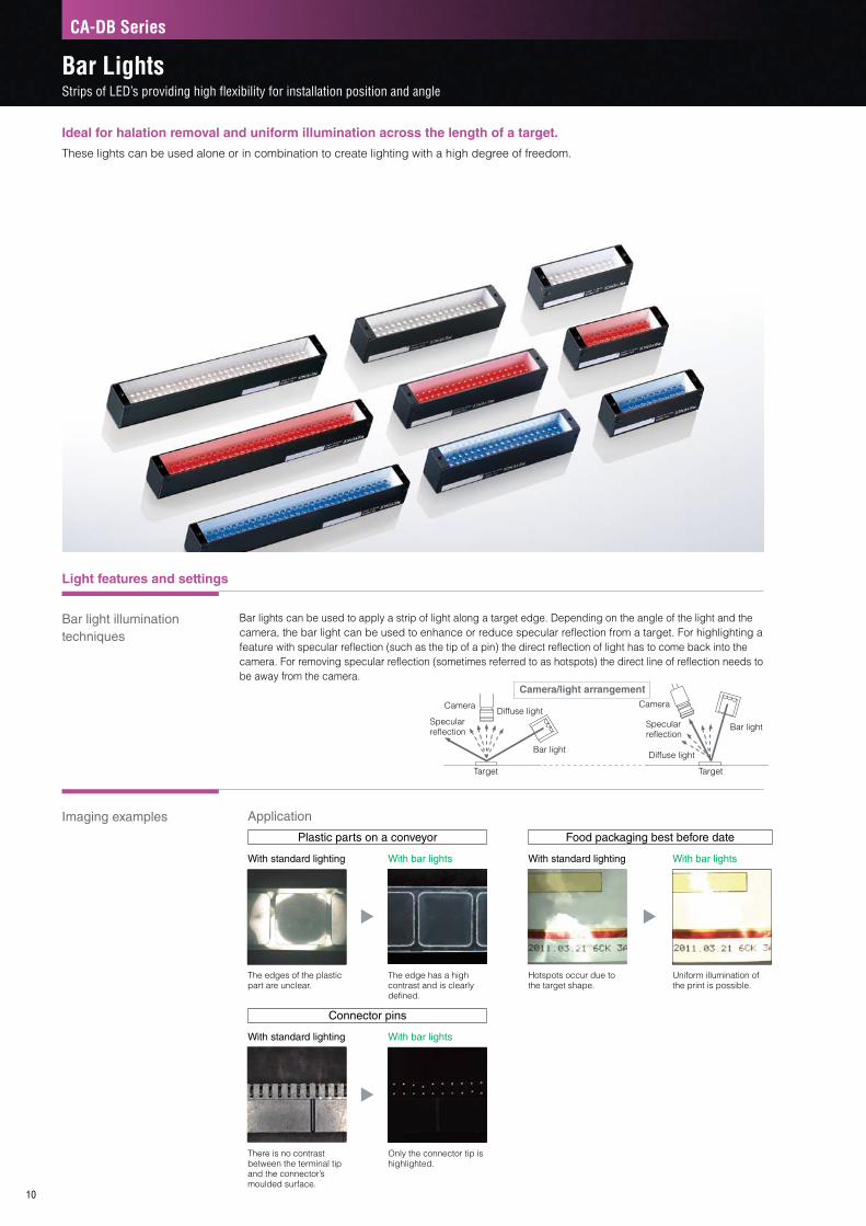
Bar light illumination techniques
Bar lights can be used to apply a strip of light along a target edge� Depending on the angle of the light and the camera, the bar light can be used to enhance or reduce specular reflection from a target� For highlighting a feature with specular reflection (such as the tip of a pin) the direct reflection of light has to come back into the camera� For removing specular reflection (sometimes referred to as hotspots) the direct line of reflection needs to be away from the camera�
Imaging examples
10
Plastic parts on a conveyor Food packaging best before date
Connector pins
With standard lighting With standard lighting
With standard lighting
With bar lights With bar lights
With bar lights
The edges of the plastic part are unclear�
Hotspots occur due to the target shape�
There is no contrast between the terminal tip and the connector’s moulded surface�
The edge has a high contrast and is clearly defined�
Uniform illumination of the print is possible�
Only the connector tip is highlighted�
Application
Camera
Specular reflection
Diffuse light
Bar light
Target
Camera
Specular reflection
Diffuse light
Bar light
Target
Camera/light arrangement
CA-DB Series
Bar LightsStrips of LED’s providing high flexibility for installation position and angle
Ideal for halation removal and uniform illumination across the length of a target.
These lights can be used alone or in combination to create lighting with a high degree of freedom�

Dimensions Unit: mm
Bar light intensity distribution (typical)
Lineup Optional parts
11
CA-DBx5 CA-DBx8
CA-DBx13
20
5060
15 17
2 x M2, d=4
L=50055
2 x M3, d=3
30
L=500
2 x M2, d=4
2 x M3, d=3
15 17
8292
87
20
50
132142
15 17
20
2 x M2, d=4
L=500
2 x M3, d=3
137
80
CA-DBx5 CA-DBx8
CA-DBx13
20
5060
15 17
2 x M2, d=4
L=50055
2 x M3, d=3
30
L=500
2 x M2, d=4
2 x M3, d=315 17
8292
87
20
50
132142
15 17
20
2 x M2, d=4
L=500
2 x M3, d=3
137
80
CA-DBx5 CA-DBx8
CA-DBx13
20
5060
15 17
2 x M2, d=4
L=50055
2 x M3, d=3
30
L=500
2 x M2, d=4
2 x M3, d=3
15 17
8292
87
20
50
132142
15 17
20
2 x M2, d=4
L=500
2 x M3, d=3
137
80
Part number LED colour Weight Power
consumptionInput
voltage
CA-DBR5 Approx. 35 g 1.7 W
12 V
CA-DBW5 Approx. 40 g 2.9 W
CA-DBB5 Approx. 40 g 2.9 W
CA-DBR8 Approx. 60 g 3.6 W
CA-DBW8 Approx. 60 g 4.8 W
CA-DBB8 Approx. 60 g 4.8 W
CA-DBR13 Approx. 80 g 4.2 W
CA-DBW13 Approx. 90 g 7.3 W
CA-DBB13 Approx. 90 g 7.3 W
Part number Applicable light
OP-42283 CA-DBx5
OP-87042 CA-DBx8
OP-42282 CA-DBx13
Part number Applicable light
OP-42281 CR-DBx5
OP-87043 CR-DBx8
OP-42280 CR-DBx13
LED imprint preventionBar illumination eliminates reflection of LEDs and irregular lighting conditions that may occur in capturing an image of a glossy target�
Glare preventionEliminate the glare on glossy targets when combined with a lens polarising filter�
CA-DBx5 CA-DBx8 CA-DBx13
The above image displays the relative brightness across a 10000 point grid for the CA-DB Series� Although the intensity varies with each model type, the associated illumination distance and relative brightness across the area are consistent�The brightest areas (shown in red) are considered 100% relative intensity and the dullest areas (shown in green) are considered 0% relative intensity� The images display the intensity differential across the area� By comparing the changes in the intensity differential for different lighting heights (LWD) the ideal lighting range can be realised with the relative brightest points being 100%�
When CA-DBW8 is used:
When CA-DBW13 is used:
* The above data are representative examples� This is not a guarantee of the product quality�* LWD is the distance from the illumination to
the measurement target�
LWD: 50 mm
LWD: 50 mm
LWD: 70 mm
LWD: 70 mm
LWD: 90 mm
LWD: 90 mm
100
0
100
0
200 mm
240 mm
Diffusion plate
Polarisation plate
Thickness: Approx� 2 mm
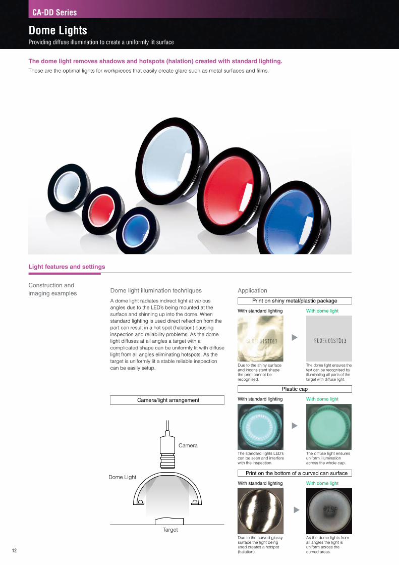
ApplicationDome light illumination techniques
A dome light radiates indirect light at various angles due to the LED’s being mounted at the surface and shinning up into the dome� When standard lighting is used direct reflection from the part can result in a hot spot (halation) causing inspection and reliability problems� As the dome light diffuses at all angles a target with a complicated shape can be uniformly lit with diffuse light from all angles eliminating hotspots� As the target is uniformly lit a stable reliable inspection can be easily setup�
Print on shiny metal/plastic package
With standard lighting With dome light
Due to the shiny surface and inconsistent shape the print cannot be recognised�
The dome light ensures the text can be recognised by illuminating all parts of the target with diffuse light�
Plastic cap
Camera/light arrangement With standard lighting With dome light
The standard lights LED’s can be seen and interfere with the inspection�
The diffuse light ensures uniform illumination across the whole cap�
Print on the bottom of a curved can surface
With standard lighting With dome light
Due to the curved glossy surface the light being used creates a hotspot (halation)�
As the dome lights from all angles the light is uniform across the curved areas�
Light features and settings
Construction and imaging examples
12
Target
Camera
Dome Light
The dome light removes shadows and hotspots (halation) created with standard lighting.
These are the optimal lights for workpieces that easily create glare such as metal surfaces and films�
CA-DD Series
Dome LightsProviding diffuse illumination to create a uniformly lit surface

CA-DDx8
CA-DDx15
55
55
L=500
20
40
26
4 -ø2.1
26
50
66
L=500
ø30
ø73
ø11
4
ø15
4.5
ø54
ø87
4 -ø2.1
CA-DDx8
CA-DDx15
55
55
L=500
20
40
26
4 -ø2.1
26
50
66
L=500
ø30
ø73
ø11
4
ø15
4.5
ø54
ø87
4 -ø2.1
CA-DDx8
CA-DDx15
55
55
L=500
20
40
26
4 -ø2.1
26
50
66
L=500
ø30
ø73
ø11
4
ø15
4.5
ø54
ø87
4 -ø2.1
CA-DDx8
CA-DDx15
55
55
L=500
20
40
26
4 -ø2.1
26
50
66
L=500
ø30
ø73
ø11
4
ø15
4.5
ø54
ø87
4 -ø2.1
Dimensions Unit: mm
Dome light intensity distribution (typical)
Lineup Application
13
The above image displays the relative brightness across a 10000 point grid for the CA-DD Series� Although the intensity varies with each model type, the associated illumination distance and relative brightness across the area are consistent�The brightest areas (shown in red) are considered 100% relative intensity and the dullest areas (shown in green) are considered 0% relative intensity� The images display the intensity differential across the area� By comparing the changes in the intensity differential for different lighting heights (LWD) the ideal lighting range can be realised with the relative brightest points being 100%�
When CA-DDW8 is used:
When CA-DDW15 is used:
* The above data are representative examples� This is not a guarantee of the product quality�* LWD is the distance from the illumination to the
measurement target�
LWD: 5 mm
LWD: 5 mm
LWD: 10 mm
LWD: 20 mm
LWD: 20 mm
LWD: 30 mm
100
0
100
0
Part number LED colour Weight Power
consumptionInput
voltage
CA-DDR8 Approx. 70 g 5.8 W
12 V
CA-DDW8 Approx. 70 g 5.8 W
CA-DDB8 Approx. 70 g 5.8 W
CA-DDR15 Approx. 130 g 11 W
CA-DDW15 Approx. 170 g 18.8 W
CA-DDB15 Approx. 170 g 18.8 W
OCR on foil package
The print on a foil package can be easily recognised even when there is a transparent layer on top�Conventionally this is difficult due to the ever changing shadows and hotspots (halation) created by the inconsistent shape of the package�
135 mm
215 mm
CA-DDx8 CA-DDx15
Light features and settings
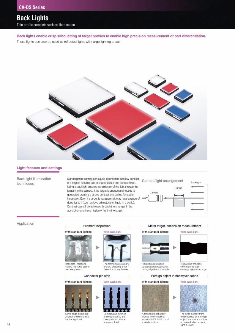
Back light illumination techniques
Application
14
Filament inspection
Connector pin strip
Metal target, dimension measurement
Foreign object in nonwoven fabric
With standard lighting
With standard lighting
With standard lighting
With standard lighting
With back light
With back light
With back light
With back light
Camera
Backlight
Target
Hot spots (halation) means filaments cannot be clearly seen�
Some edge points are unclear and blend into the background�
Hot spots and inconsistent contrast occurs across the part making edge detection unstable�
A foreign object easily blends into the fabric, especially if it is thin or of a similar colour�
The filaments are clearly shown, enabling clear detection of any breaks�
Complicated outlines and edge points are clearly shown with a sharp contrast�
The backlight ensures a silhouette of the target creating a high contrast edge�
The extra density from the presence of a foreign object ensures a shadow is created when a back light is used�
Camera/light arrangement
Back lights enable crisp silhouetting of target profiles to enable high precision measurement or part differentiation.
These lights can also be used as reflected lights with large lighting areas�
CA-DS Series
Back LightsThin profile complete surface illumination
Standard front lighting can cause inconsistent and low contrast of a targets features due to shape, colour and surface finish� Using a backlight ensures transmission of the light through the target into the camera� If the target is opaque a silhouette is generated creating a strong contrast and outline for stable inspection� Even if a target is transparent it may have a range of densities to it (such as layered material or liquid in a bottle)� Contrast can still be achieved through the changes in the absorption and transmission of light in the target�

Back light intensity distribution (typical)
Lineup Application
15
Dimensions Unit: mm
LWD: 5 mm
LWD: 10 mm
LWD: 10 mm
LWD: 20 mm
LWD: 20 mm
LWD: 30 mm
100
0
100
0
When CA-DSW3 is used:
When CA-DSW15 is used:
CA-DSW/B2CA-DSR2
CA-DSR3 CA-DSW/B3
CA-DS□9CA-DS□7 CA-DS□15
L=500
9177
97
607778
11.7
L=500
10692
112
709293
8.2
L=500
150164170
120
150
151
17.2
L=500
153233
324346
11.7
8.2
406263
324346
L=500
11.7
406263
324346
L=500
8.2
L=500
324346
2 x ø3.5
2 x ø3.5 2 x ø3.5
2 x ø3.5
4 x ø3.54 x ø3.5
4 x ø3.5
153233
Part number LED colour Weight Power
consumptionInput
voltage
CA-DSR2 Approx. 30 g 2.2 W
12 V
CA-DSW2 Approx. 30 g 2.9 W
CA-DSB2 Approx. 30 g 2.9 W
CA-DSR3 Approx. 40 g 3.6 W
CA-DSW3 Approx. 40 g 5.8 W
CA-DSB3 Approx. 40 g 5.8 W
CA-DSR9 Approx. 110 g 14 W
CA-DSW7 Approx. 90 g 18 W
CA-DSB7 Approx. 90 g 18 W
CA-DSR15* Approx. 320 g 27.4 W
CA-DSW15* Approx. 320 g 27.4 W
CA-DSB15* Approx. 320 g 27.4 W
* CA-DC100 cannot be used to provide maximum intensity as power consumption exceeds 20 W�
Transparent liquid level
Liquid level can be easily detected inside of a bottle due to the different transmission characteristics of the bottle compared to the bottle and liquid together�At the same time the vision system can perform other required inspections such as label position or a loose/cocked cap�
155 mm
255 mm
CA-DSR2
CA-DSR3
CA-DSW/B2
CA-DSW/B3
CA-DSx7
CA-DSR9
CA-DSx15
* The data to the left are representative examples� This is not a guarantee of the product quality�
* LWD is the distance from the illumination to the measurement target�
The image to the left displays the relative brightness across a 10000 point grid for the CA-DS Series� Although the intensity varies with each model type, the associated illumination distance and relative brightness across the area are consistent�The brightest areas (shown in red) are considered 100% relative intensity and the dullest areas (shown in green) are considered 0% relative intensity� The images display the intensity differential across the area� By comparing the changes in the intensity differential for different lighting heights (LWD) the ideal lighting range can be realised with the relative brightest points being 100%�

Wavelength conversion sheet features
Wavelength conversion mechanism
Combining the wavelength conversion sheet, blue LED light, and blue cut filter create an absolutely new piece of light technology that can be used to realise back light images with reflected light�
16
Industry’s first
This is the image obtained when the white workpiece is placed on top of the wavelength conversion sheet and the white sheet�
This is the image obtained when the blue light is emitted� The white background and the white sheet are imaged in blue� The waveform conversion sheet converts the blue light to an orange colour tinged with red and reflects this colour�
The blue cut filter cuts out the reflected light in the blue range, and only the light from the wavelength conversion sheet enters the lens� In this way, an image like that captured of the white workpiece with a back light is obtained�
White background
White workpiece
Wavelength conversion
sheet
With only the ambient light
Install a blue bar light.
In addition, install a blue cut filter on the lens.
Making it possible to use back lights in locations where it was only possible to install reflected lights.
Some inspections are normally stabilised through the use of back lights� However there are situations where back lights cannot be installed, possibly due to a lack of installation space or an inability to wire around moving parts� In these cases, back lights can be emulated by attaching a wavelength conversion sheet and installing blue reflected lights�
CA-DWC Series
Wavelength Conversion SheetMaking possible inspections with back lights in locations where it was difficult to install back lights

Even in locations where it seemed impossible to install back lights
Application
Lineup
17
• For details on the blue cut filter, see page 48�
AlignmentIt’s difficult to route cables when embedding light in a moving stage, but there are times when the contrast with just reflected light is insufficient� By using the wavelength conversion sheet, it’s possible to realise back light images without any wiring, which makes stable detections possible�
Liquid surface inspectionAssume that there is no space to install a back light when performing liquid surface inspections at a filling machine and that reflected light has to be used instead� Even if the light is installed in a narrow space, back light images can be realised by wrapping the wavelength conversion sheet around the rotating object�
The contrast for the alignment mark is insufficient, so stable detection is not possible�
Due to the effect of the reflection from the workpiece surface, it is not possible to obtain a stable view of the liquid surface�
The contrast obtained is equivalent to that of images captured with back lights, which improves the alignment precision�
There may be foreign substances on the surface of the wavelength conversion sheet� However, even if such substances are present, the product is still within the inspection standards, and these substances do not indicate that the product is defective�
Only the liquid surface is clearly imaged as a back light image, which makes it possible to perform stable liquid surface inspections�
Part number CA-DWC30Peak wavelength after conversion 615 nm
Conversion efficiency*1 Approx. 80 to 90%
Sheet size*2 A4 (210 × 297 mm), thickness: 0.2 mm
Sheet composition
(1) Laminate Polyester film (transparent, sand mat treatment)
(2) Special wavelength converting material
(3) Foamed polyester film (white)
(4) Highly adhesive, re-peelable adhesive (acrylic adhesive)*3
(5) Graduated grid
Weight Approx. 20 g (including the peelable sheet)
*1 This is the value only for the special wavelength converting material�
*2 The wavelength converting material is pasted on the entirety of the A4-sized surface� There are no margins�
*3 Adhesive strength: 9�4 N/25 mm 30 minutes after application, 10�8 N/25 mm 24 hours after application
• In environments with low or high temperatures, the adhesive strength and the maintenance of adhesion decrease, which makes it easy for the sheet to peel off�
• The sheet’s adhesive capability and capability to be peeled off repeatedly may be affected by the shape of the object that the sheet is affixed to as well as by the usage environment and conditions� Also, if there are concerns regarding the sheet being peeled off or becoming dirty, the sheet can be used with a cover made of glass, acrylic, or a similar material in place over top of it� In this situation, the brightness may be slightly attenuated due to the glass or other material�
• If the surface is dirty, wipe it clean with a soft cloth to which a neutral cleaning solution with no abrasive has been applied�• Scissors or a box cutter can be used to cut the sheet to a different size�
Using only blue reflected light
Using only blue reflected light
Using the wavelength conversion sheet
Using the wavelength conversion sheet

Light features and settings
Coaxial light illumination techniques
Application
18
Camera/light arrangement
Camera
Coaxial light
Half mirror
Specular reflection
Target
Pressed part
Metal processed parts
Screw head
Glass parts
With standard lighting
With standard lighting
With standard lighting
With standard lighting
With coaxial light
With coaxial light
With coaxial light
With coaxial light
Edges are not clear as diffuse and specular light is received by the camera�
Marking is unclear�
Various light components are reflected at all angles causing inconsistent images from part to part�
Specular reflection causes lights to appear on the glass surface�
The recessed areas diffuse light so they appear dark and the edges can be easily identified�
The edges of the marking are clearly defined�
The change from curved to flat is clearly identified and the flat area is highlighted well to the camera�
Uniform illumination is possible�
This illumination style provides high contrast, because only specular-reflection light is reflected back to the camera, while diffuse light from a recess or edge is not.
These lights are effective when inspecting mirror surfaces and glossy surfaces and when distinguishing between objects according to differences in glossiness�
CA-DX Series
Coaxial Lights (Vertical)Coaxial vertical illumination emits light on the same axis as the camera and lens.
The co-axial light transmits light from the side onto a half way mirror� The mirror reflects the light onto the target�Specular reflected light is allowed to pass back up to the camera whereas as diffuse reflected light from the target is rejected� This in turn causes a contrast at the edge points of a target�In addition, the further the light is from the target the greater the rejection of diffused light becomes, creating greater image contrast and definition�

Coaxial light intensity distribution (typical)
Lineup Application
19
CA-DXx3
CA-DXx5
CA-DXx7
1010
90.8 0.8124 x M3, d=3
L=50027
Glass plateHalf mirror
2 x M3, d=341
6 18
58.5
2030 12
11 60
14
50
4 x M4, d=5
14
5579
50
L=500
2 x 2 x M4, d=51
Glass plateHalf mirror
120
5082
17 50
10 40
15
32
4 x M4, d=5
59
L=500Glass plateHalf mirror
40
8097
3660
16 32
2 x M4, d=5
2.4 2.4
2.4 2.4
Dimensions Unit: mm
CA-DXx3
CA-DXx5
CA-DXx7
LWD: 5 mm
LWD: 5 mm
LWD: 10 mm
LWD: 20 mm
LWD: 15 mm
LWD: 40 mm
100
0
100
0
When CA-DXW3 is used:
When CA-DXW7 is used:
Part number LED colour Weight Power
consumptionInput
voltage
CA-DXR3 Approx. 60 g 1.8 W
12 V
CA-DXW3 Approx. 60 g 1.9 W
CA-DXB3 Approx. 60 g 1.9 W
CA-DXR5 Approx. 230 g 5 W
CA-DXW5 Approx. 230 g 4.9 W
CA-DXB5 Approx. 230 g 4.9 W
CA-DXR7 Approx. 380 g 6.7 W
CA-DXW7 Approx. 380 g 10.1 W
CA-DXB7 Approx. 380 g 10.1 W
Pressed/stamped part sortingSorting parts and identifying components is possible through profile recognition or stamped markings due to the diffused light from the recessed edge�
65 mm
175 mm
* The data to the left are representative examples� This is not a guarantee of the product quality�
* LWD is the distance from the illumination to the measurement target�
The image to the left displays the relative brightness across a 10000 point grid for the CA-DX Series� Although the intensity varies with each model type, the associated illumination distance and relative brightness across the area are consistent�The brightest areas (shown in red) are considered 100% relative intensity and the dullest areas (shown in green) are considered 0% relative intensity� The images display the intensity differential across the area� By comparing the changes in the intensity differential for different lighting heights (LWD) the ideal lighting range can be realised with the relative brightest points being 100%�
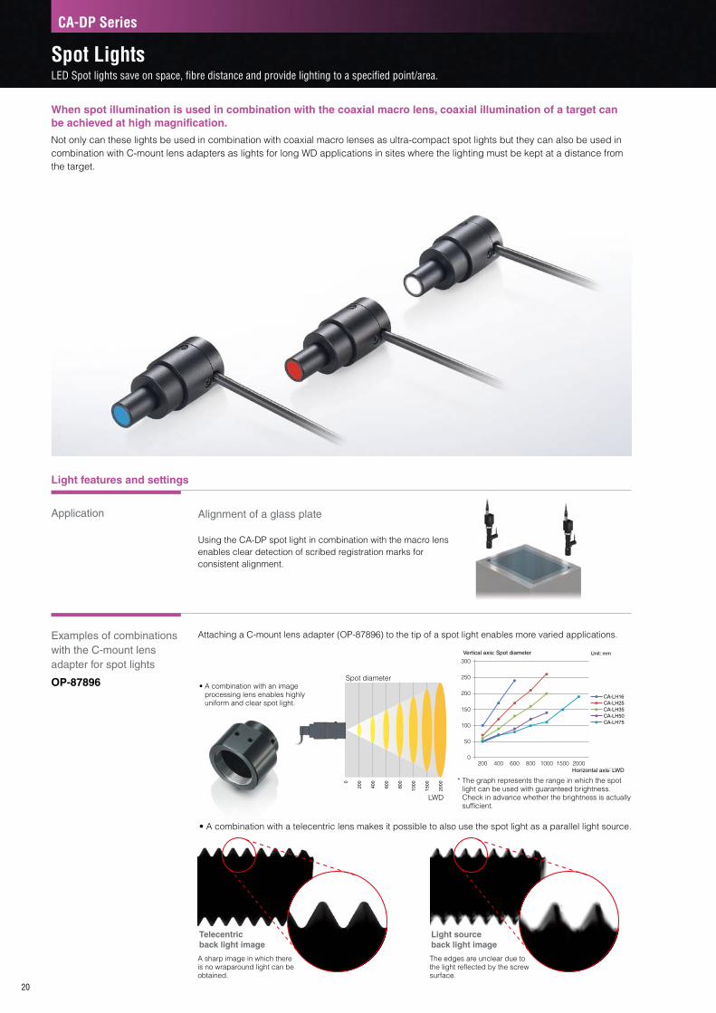
Light features and settings
Application
Examples of combinations with the C-mount lens adapter for spot lights
OP-87896
Attaching a C-mount lens adapter (OP-87896) to the tip of a spot light enables more varied applications�
20
Spot diameter
LWD
Using the CA-DP spot light in combination with the macro lens enables clear detection of scribed registration marks for consistent alignment�
• A combination with an image processing lens enables highly uniform and clear spot light�
• A combination with a telecentric lens makes it possible to also use the spot light as a parallel light source�
* The graph represents the range in which the spot light can be used with guaranteed brightness� Check in advance whether the brightness is actually sufficient�
Alignment of a glass plate
300
250
200
150
100
50
0200 400 600 800 1000 1500 2000
CA-LH75
Horizontal axis: LWD
Vertical axis: Spot diameter Unit: mm
CA-LH50CA-LH35CA-LH25CA-LH16
0
200
400
600
800
1000
1500
2000
Telecentric back light image
Light source back light image
A sharp image in which there is no wraparound light can be obtained�
The edges are unclear due to the light reflected by the screw surface�
When spot illumination is used in combination with the coaxial macro lens, coaxial illumination of a target can be achieved at high magnification.
Not only can these lights be used in combination with coaxial macro lenses as ultra-compact spot lights but they can also be used in combination with C-mount lens adapters as lights for long WD applications in sites where the lighting must be kept at a distance from the target�
CA-DP Series
Spot LightsLED Spot lights save on space, fibre distance and provide lighting to a specified point/area.
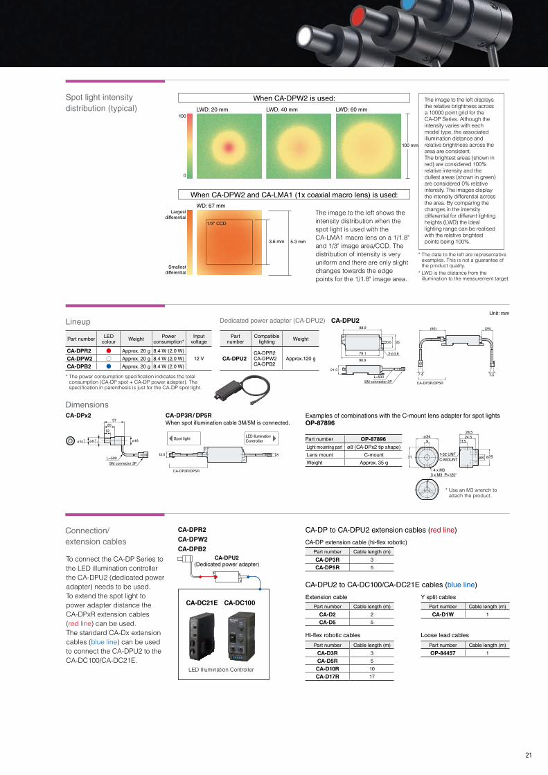
Spot light intensity distribution (typical)
Lineup
Connection/ extension cables
21
LWD: 20 mm
WD: 67 mm
LWD: 40 mm LWD: 60 mm100
0
100 mm
Largest differential
Smallest differential
When CA-DPW2 is used:
When CA-DPW2 and CA-LMA1 (1x coaxial macro lens) is used:
5.3 mm
The image to the left shows the intensity distribution when the spot light is used with the CA-LMA1 macro lens on a 1/1�8" and 1/3" image area/CCD� The distribution of intensity is very uniform and there are only slight changes towards the edge points for the 1/1�8" image area�
1/3" CCD
3.6 mm
Dedicated power adapter (CA-DPU2)
Part number LED colour Weight Power
consumption*Input
voltage
CA-DPR2 Approx. 20 g 8.4 W (2.0 W)
12 VCA-DPW2 Approx. 20 g 8.4 W (2.0 W)
CA-DPB2 Approx. 20 g 8.4 W (2.0 W)
Part number
Compatible lighting Weight
CA-DPU2CA-DPR2CA-DPW2CA-DPB2
Approx.120 g
Part number Cable length (m)
CA-D2 2
CA-D5 5
Part number Cable length (m)
CA-D1W 1
Part number Cable length (m)
CA-D3R 3
CA-D5R 5
CA-D10R 10
CA-D17R 17
Part number Cable length (m)
CA-DP3R 3
CA-DP5R 5
CA-DPU2 to CA-DC100/CA-DC21E cables (blue line)
CA-DP to CA-DPU2 extension cables (red line)
* The power consumption specification indicates the total consumption (CA-DP spot + CA-DP power adapter)� The specification in parenthesis is just for the CA-DP spot light�
To connect the CA-DP Series to the LED illumination controller the CA-DPU2 (dedicated power adapter) needs to be used�To extend the spot light to power adapter distance the CA-DPxR extension cables (red line) can be used� The standard CA-Dx extension cables (blue line) can be used to connect the CA-DPU2 to the CA-DC100/CA-DC21E�
Extension cable Y split cables
Part number Cable length (m)
OP-84457 1
Loose lead cablesHi-flex robotic cables
CA-DP extension cable (hi-flex robotic)
CA-DC21E CA-DC100
CA-DPU2(Dedicated power adapter)
LED Illumination Controller
CA-DPx2 CA-DP3R/ DP5RWhen spot illumination cable 3M/5M is connected.
CA-DPU2
L=500
SM connector 3P
-0.1 0
-0.1 0
12
ø14 ø16ø8
2037
SM connector 2PL=500
21.3
2-ø3.6
35
88.9
79.1
96.9
25
LED illuminationController
Spot light
813.5
CA-DP3R/DP5R
7.57.4
(25)(60)
CA-DP3R/DP5R
CA-DPx2 CA-DP3R/ DP5RWhen spot illumination cable 3M/5M is connected.
CA-DPU2
L=500
SM connector 3P
-0.1 0
-0.1 0
12
ø14 ø16ø8
2037
SM connector 2PL=500
21.3
2-ø3.6
35
88.9
79.1
96.9
25
LED illuminationController
Spot light
813.5
CA-DP3R/DP5R
7.57.4
(25)(60)
CA-DP3R/DP5R
CA-DPx2 CA-DP3R/ DP5RWhen spot illumination cable 3M/5M is connected.
CA-DPU2
L=500
SM connector 3P
-0.1 0
-0.1 0
12
ø14 ø16ø8
2037
SM connector 2PL=500
21.3
2-ø3.6
35
88.9
79.1
96.9
25
LED illuminationController
Spot light
813.5
CA-DP3R/DP5R
7.57.4
(25)(60)
CA-DP3R/DP5R
CA-DPx2 CA-DP3R/ DP5RWhen spot illumination cable 3M/5M is connected.
CA-DPU2
L=500
SM connector 3P
-0.1 0
-0.1 0
12
ø14 ø16ø8
2037
SM connector 2PL=500
21.3
2-ø3.6
35
88.9
79.1
96.9
25
LED illuminationController
Spot light
813.5
CA-DP3R/DP5R
7.57.4
(25)(60)
CA-DP3R/DP5R
CA-DPR2
CA-DPW2
CA-DPB2
Part number OP-87896Light mounting part ø8 (CA-DPx2 tip shape)
Lens mount C-mount
Weight Approx. 35 g
Examples of combinations with the C-mount lens adapter for spot lights OP-87896 OP-87896
ø34
ø8 ø25311-32 UNFC-MOUNT
3 x M3 P=120°4 x M3
28.5
924.5
11.5
* Use an M3 wrench to attach the product�
CA-DPU2
Dimensions
Unit: mm
* The data to the left are representative examples� This is not a guarantee of the product quality�
* LWD is the distance from the illumination to the measurement target�
The image to the left displays the relative brightness across a 10000 point grid for the CA-DP Series� Although the intensity varies with each model type, the associated illumination distance and relative brightness across the area are consistent�The brightest areas (shown in red) are considered 100% relative intensity and the dullest areas (shown in green) are considered 0% relative intensity� The images display the intensity differential across the area� By comparing the changes in the intensity differential for different lighting heights (LWD) the ideal lighting range can be realised with the relative brightest points being 100%�

Lineup
Application
22
CA-DLR7
CA-DLR12
CA-DLR10
10
4x M3, d=3
L=500
22
3x M2, d=3.5
4x M3, d=6
L=50 0
L=50010
4x M3, d=3ø75ø56ø46
ø100ø84ø68
ø125ø110ø95
CA-DLR7
CA-DLR12
CA-DLR10
10
4x M3, d=3
L=500
22
3x M2, d=3.5
4x M3, d=6
L=50 0
L=50010
4x M3, d=3ø75ø56ø46
ø100ø84ø68
ø125ø110ø95
CA-DLR7 CA-DLR12
Part number LED colour Weight Power
consumptionInput
voltage
CA-DLR7 Approx. 40 g 2 W12 V
CA-DLR12 Approx. 85 g 3.3 W
Application
Surface/edge chipTypically, surface and edge defects are hard to detect with standard lighting as there is little contrast change� The low angle light highlights the physical change in the target making detection possible�
With standard lighting With standard lightingWith low angle illumination With low angle illumination
Camera/ light arrangement
Low angle lighting provides direct light at a shallow angle onto the target� Typically inspection of the edge of a target or physical flaws on the surface are hard to detect with standard direct lighting� As the direction of the light is almost parallel to the surface any change in surface height deflects the normal path of light to the camera, subsequently highlighting the change�
The chip cannot be recognised�
The shape of the bottle lip cannot be easily recognised�
The chip is highlighted and easily recognisable�
All the edges of the lip are highlighted showing deformed areas�
Non-uniform bottle lipChipped edge
Low angle light illumination techniques
Dimensions Unit: mm
Low-angle illumination provides a high contrast to an edge, recess or a protrusion against their normal background.
These lights make just the edges and contours of the target stand out by shining LED light at shallow angles and nearly horizontally�
CA-DL Series
Low Angle LightsOpposing LED’s with shallow incidence angle to provide low angle illumination

CA-DQx10
CA-DQx15
L=50 0
8 x M2d=3
63.4
109
55
17
109
27 .960
70
60 70
4 x M3Throughhole
L=500
8 x M2d=487
95.4
150
17
150
27.94 x M3
Throughhole102110
110
102
CA-DQx10
CA-DQx15
L=50 0
8 x M2d=3
63.4
109
55
17
109
27 .960
70
60 70
4 x M3Throughhole
L=500
8 x M2d=487
95.4
150
17
150
27.94 x M3
Throughhole102110
110
102
Lineup
Application
23
Dimensions Unit: mm
IC surface flaw
Optional parts
Part number LED colour Weight Power
consumption*Input
voltage
CA-DQR10 Approx. 370 g 8.6 W
12 V
CA-DQW10 Approx. 370 g 11.5 W
CA-DQB10 Approx. 370 g 11.5 W
CA-DQR15 Approx. 520 g 14.4 W
CA-DQW15 Approx. 520 g 19.2 W
CA-DQB15 Approx. 520 g 19.2 W
Part number * Applicable light
OP-42283 CA-DQx10
OP-87042 CA-DQx15
Using four bar lights in a square arrangement allows for adjustment in four independent directions� Optimal lighting according to the target profile can be set to highlight and extract specific characteristics�
Pattern 1 Pattern 2 Pattern 3 Pattern 4
By switching through different patterns of lighting a surface flaw can be easily highlighted and detected�
Thickness: Approx� 2 mm
* These models are for a single bar� Four sets are required for the whole square�
Pattern 1
Pattern 3
ICIC
CA-DQx10 CA-DQx15
Square light illumination techniques
* Total value of four bars
Pat
tern
4
Pat
tern
2
Illumination of a target can be freely controlled, by changing the angle and choosing which sides of the target should be lit.
These units are made of lights in four directions whose angles, light intensities, and lighting timings can be set separately, which makes it possible to perform previously difficult inspections�
CA-DQ Series
Square Lights (Direct)The square lights are made up of four bars lights, which can be individually controlled and positioned.
Application
Inspection of sealantThe presence/absence of sealant can be checked across the whole target area� By adjusting the installation distance and angle the whole target can be uniformly lit�

Technical Guide
Selection of lighting for line scan cameras
When using line scan cameras, it is not necessary to illuminate the entire target� Therefore, images can be taken using a narrow area of the part� Illumination of the target can be classified in three ways�
Diffuser plate and polarising plate
Use diffuser plates and polarising plates to effectively utilise light for an application�
24
Diffuser plateDiffuser plates are sheets or films that uniformly diffuse light to the entire surface� Ground glass used to be popular, but plastics are more common now� In recent years, diffuser plates are used as a part of backlights mounted on the rear of liquid crystal display panels�
Defective areas will appear as black since light does not return to the camera if there are flaws or dents�
Defective areas will appear as white by light applied to burrs and convex flaws reflecting towards the camera�
This is a method often used for measuring dimensions and for inspecting foreign objects on a sheet� Transmissive lighting will enhance the edges, and blockage of light will cause foreign objects to appear black when inspecting for foreign objects�
[Feature] [Feature][Feature]
Specular reflection Diffuse reflection Transmission
Target Target
Target
Bar light Bar light
Bar light
Camera Camera Camera
Emits stable light intensity in a concentrated line
By using lenses to concentrate high-intensity LED illumination, we have created lights that can support high-speed lines�
CA-DZ Series
Line LightsHigh-intensity LED lights designed for line scan camera applications

CA-DZx5
2 x M5, d=6459.7
50
7.1
83.5
29.5
2 x M5, d=6
2 x M5, d=645
9.740
0.7
3
(90°)L=500
CA-DZx15
2 x M5, d=6144
9.7
7.1
150
173.6
29.5
2 x M5, d=6
2 x M5, d=69.7
144
(90°)L=500
400.7
3
CA-DZx30
3 x M5, d=6144 144
9.7
300
7.1
323.6
29.5
3 x M5, d=6
3 x M5, d=6
9.7
144 144
(90°)L=500
400.7
3
CA-DZx45
4 x M5, d=6144 144 144
9.7
450
7.1
473.6
29.5
4 x M5, d=6
4 x M5, d=69.7
144 144 144
(90°)L=500
400.7
3
B 3 x M5, d=6
9.7B
3 x M5, d=6
A
29.5
B9.7
40
3 x M5, d=6(90°)
L=500
71.2
Lineup Optional parts
25
Dimensions Unit: mm
CA-DZx5
CA-DZx45
CA-DZx15 CA-DZx30
CA-DZxxxWhen connecting the diffusion unit for transmission
Part numberDimension
A B
CA-DZx5 83.5 45
CA-DZx15 173.6 144
CA-DZx30 323.6 288
CA-DZx45 473.6 432
Part number LED colour Weight Power
consumption*Input
voltage
CA-DZR5Approx. 240 g
2.5 W
12 V
CA-DZW54.7 W
CA-DZB5
CA-DZR15Approx. 480 g
7.6 W
CA-DZW1514.2 W
CA-DZB15
CA-DZR30Approx. 880 g
15.1 W
CA-DZW3028.4 W*
CA-DZB30
CA-DZR45Approx. 1280 g
22.7 W*
CA-DZW4528.4 W*
CA-DZB45
* CA-DC100 cannot be used to provide maximum intensity as power consumption exceeds 20 W�
* When using a line camera with the CA-DC21E, set light configuration to DC mode�
* CA-DZBx and CA-DZWx: Class 2 LED Product (IEC60825-1) CA-DZRx: Class 1M LED Product (IEC60825-1)�
Part number Applicable light
OP-87320 CA-DZx5
OP-87321 CA-DZx15
OP-87322 CA-DZx30
OP-87323 CA-DZx45
One-sided matte processing diffusion plate
One-sided matte processing plate is included with the main line light unit�
Part number Applicable light
OP-87324 CA-DZx5
OP-87325 CA-DZx15
OP-87326 CA-DZx30
OP-87327 CA-DZx45
Two-sided matte processing diffusion plate
Two-sided matte plate has a diffusion rate that is much higher than one-sided matte plate�
Part number Applicable light
OP-87328 CA-DZx5
OP-87329 CA-DZx15
OP-87330 CA-DZx30
OP-87331 CA-DZx45
Diffusion unit for transmission
Limits light diffusion and enhances the edges of the target for dimensional type measurements (backlight)�
Thickness: Approx� 3 mm
Thickness: Approx� 3 mm

Minimal wiring
Strobe lighting
Specifications
26
Power supplies that enable the full capabilities of lights
Minimal wiring
CA-DC30E (For XG/CV-X Series only. For use when combined with the CA-DRWxX Series only.)
CA-DC21E (Dedicated for CV-5000/XG/CV-X Series) CA-DC10E (Dedicated for CV-X100 Series)
* This applies to the case when the CA-DC21E is used� When the CA-DC10E is used, only 1 unit can be connected� When the CA-DC30E is used, up to 2 units can be connected (additionally, 2 CA-DC21E units can be mixed in)�
The LED lighting controller can be connected directly to the vision system with the minimal amount of wiring required� The controller enables direct illumination control and light strobing in conjunction with image capture trigger inputs without the need for a PLC� Up to 4 illumination expansion units* can be connected to a single vision system, enabling up to 8 lights to be connected in any combination without wiring�
LED illumination is the norm for machine vision due to its flexibility and lifetime characteristics� However due to complex wiring and sequencing the fast switching performance of LED’s may not be maximised and the light is left continuously on�The CA-DC30E/CA-DC21E/CA-DC10E automatically enables strobing of light sources by default without the need for wiring or complex programming� This results in a significantly longer service life�
ControllerIllumination expansion units
Imaging Image processing
Imaging Image processing
Imaging Image processing
Imaging Image processing
The ON time is reduced significantly while the service life becomes ten times longer�
Lit
Lit Unlit UnlitLit
Continuous lighting (wasted ON time is included)
Strobe lighting
Transmission Transmission
Transmission Transmission
CA-DC Series
Illumination ControllerPower and control of LED light sources.
Part number CA-DC30E CA-DC21E CA-DC10E
Output
Light control method Constant voltage control method
(1) Constant voltage control method (direct current light)
(2) Pulse width modulation method (light emitting frequency: 100 kHz)
[System setting]
Pulse width modulation method
(light emitting frequency: 100 kHz)
Intensity range 255 level digital [Program setting]
Connection points 2 ch (dedicated 6-pole circular connector)
2 ch (Enables LED connector connection and terminal block connection)
Voltage LumiTrax light dedicated power supply 12 VDC/24VDC [DIP switch setting] 12 VDC
Capacity Max. 81 W Max. 40 W (30 W/1 ch maximum)
Synchronisation Camera trigger/shutter speed synchronisation FLASH output synchronisation/continuous lighting [Program setting]
Response speed Under 1 ms
(1) Constant voltage control: under 10 ms during 12 V output, under 20 ms during 24 V output
(2) Pulse width modulation method: under 1 ms during 12/24 V output
Under 1 ms
Input Forced light stop - Input rating max. 26.4 V, max. 2 mA
Display LED display Light recognised: green, disconnection error: red
Light intensity: display green/orange (over 128)Error displayed: red (all lit)
Rating
Power supply voltage 24 VDC ±10%
Current consumption*3 5 A (at maximum load) 3.0 A (12 V output at maximum load)
6.5 A (24 V output at maximum load) 3.0 A
Environmental resistance*1
Ambient temperature 0 to +50°C*2
Ambient humidity 35 to 85% RH (No condensation)
Weight Approx. 430 g Approx. 590 g Approx. 300 g
*1 The environmental resistance of the LED lighting is ambient temperature of 0 to +40°C, ambient humidity 35 to 65% RH (no condensation)*2 You will be restricted by the ambient temperature tolerance of the connected controller*3 Maximum load including inrush current at start-up
Optional parts
Precautions for using LED illumination
Specifications/Dimensions
27
Unit: mm
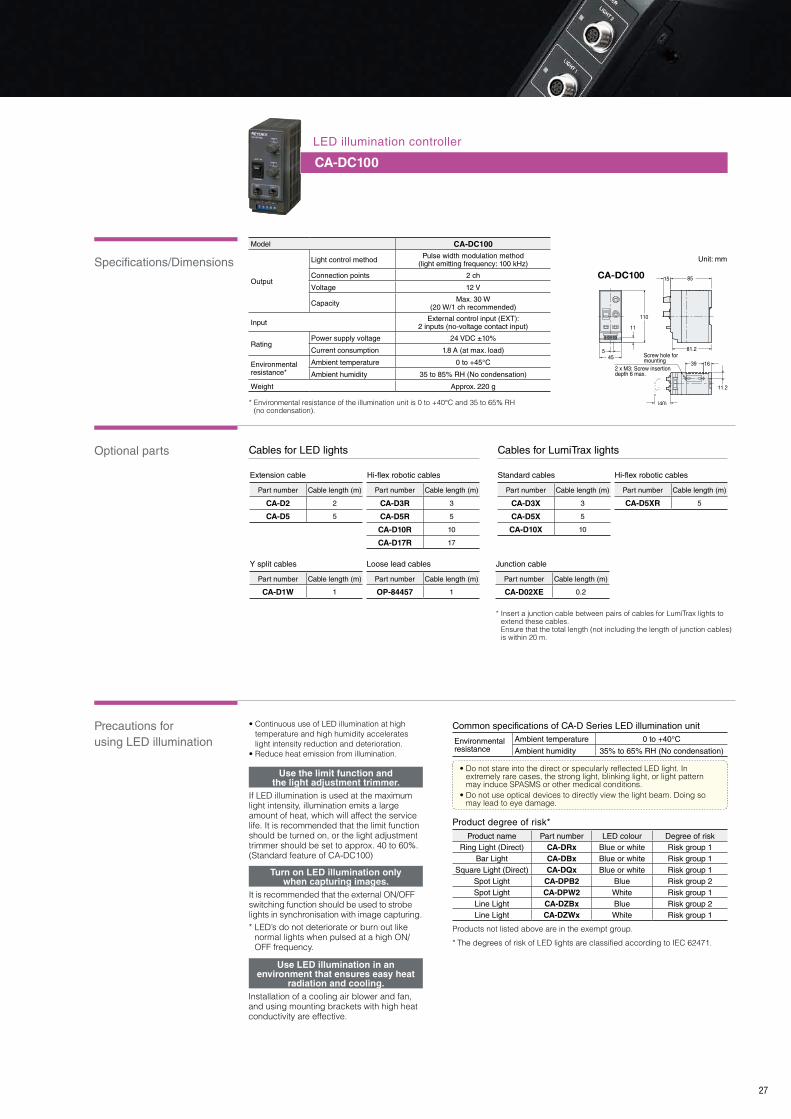
LED illumination controller
CA-DC100
• Do not stare into the direct or specularly reflected LED light� In extremely rare cases, the strong light, blinking light, or light pattern may induce SPASMS or other medical conditions�
• Do not use optical devices to directly view the light beam� Doing so may lead to eye damage�
CA-DC100
Screw hole for mounting
2 x M3: Screw insertion depth 6 max.
81.2
(40)
545
110
11
39
11.2
8515
16
• Continuous use of LED illumination at high temperature and high humidity accelerates light intensity reduction and deterioration�
• Reduce heat emission from illumination�
If LED illumination is used at the maximum light intensity, illumination emits a large amount of heat, which will affect the service life� It is recommended that the limit function should be turned on, or the light adjustment trimmer should be set to approx� 40 to 60%� (Standard feature of CA-DC100)
It is recommended that the external ON/OFF switching function should be used to strobe lights in synchronisation with image capturing�* LED’s do not deteriorate or burn out like
normal lights when pulsed at a high ON/OFF frequency�
Installation of a cooling air blower and fan, and using mounting brackets with high heat conductivity are effective�
Use LED illumination in an environment that ensures easy heat
radiation and cooling.
Use the limit function and the light adjustment trimmer.
Turn on LED illumination only when capturing images.
Model CA-DC100
Output
Light control method Pulse width modulation method(light emitting frequency: 100 kHz)
Connection points 2 ch
Voltage 12 V
Capacity Max. 30 W(20 W/1 ch recommended)
Input External control input (EXT):2 inputs (no-voltage contact input)
RatingPower supply voltage 24 VDC ±10%
Current consumption 1.8 A (at max. load)
Environmental resistance*
Ambient temperature 0 to +45°C
Ambient humidity 35 to 85% RH (No condensation)
Weight Approx. 220 g
Environmental resistance
Ambient temperature 0 to +40°C
Ambient humidity 35% to 65% RH (No condensation)
Product name Part number LED colour Degree of riskRing Light (Direct) CA-DRx Blue or white Risk group 1
Bar Light CA-DBx Blue or white Risk group 1Square Light (Direct) CA-DQx Blue or white Risk group 1
Spot Light CA-DPB2 Blue Risk group 2Spot Light CA-DPW2 White Risk group 1Line Light CA-DZBx Blue Risk group 2Line Light CA-DZWx White Risk group 1
Part number Cable length (m)
CA-D2 2
CA-D5 5
Part number Cable length (m)
CA-D5XR 5
Part number Cable length (m)
CA-D3R 3
CA-D5R 5
CA-D10R 10
CA-D17R 17
Part number Cable length (m)
CA-D3X 3
CA-D5X 5
CA-D10X 10
Common specifications of CA-D Series LED illumination unit
Product degree of risk*
Extension cable Hi-flex robotic cables
Part number Cable length (m)
CA-D02XE 0.2
Junction cable
Part number Cable length (m)
CA-D1W 1
Y split cables
Hi-flex robotic cables Standard cables
Cables for LumiTrax lightsCables for LED lights
Part number Cable length (m)
OP-84457 1
Loose lead cables
* Environmental resistance of the illumination unit is 0 to +40°C and 35 to 65% RH (no condensation)�
Products not listed above are in the exempt group�
* The degrees of risk of LED lights are classified according to IEC 62471�
* Insert a junction cable between pairs of cables for LumiTrax lights to extend these cables� Ensure that the total length (not including the length of junction cables) is within 20 m�

Specular reflection and diffuse reflection
Selecting correct illumination based on colour
Illumination wavelength characteristics
Target surface conditions (colour, glossiness, surface finish, etc�) vary
depending on the type of target� Glossiness is an important point to keep in
mind when you set an illumination angle for your lighting� When light with
equal intensity is applied to a glossy and matte target at the same angle,
specular-reflection light components are intensified with the glossy area,
while diffuse-reflection light components are intensified with the matte area�
By adjusting the illumination or camera angle based on this characteristic,
a glossy part can be intensified, or darkened helping to ensure stable
repeatable inspection of a target�
28
Effective use of illuminationTechnical Guide
A red candy wrapper is placed in a brown carton box� The images below show the contrast levels
when white, red and blue illumination is used�
To enhance target features the scatter ratio of the light can be used to good effect�
Due to blues short wavelength its scattering ratio is high unlike red light� Hence
blue lighting can enhance scratches and surface flaws that may not be shown with
red lighting�
In the examples to the right the effect of using blue and red light can be clearly seen� Depending on the application, blue light might
be ideal to enhance flaws and create a reliable inspection� Whereas red light might be a better choice to eliminate surface finish to
help prevent a false reject when inspecting a part�
Light source Label
Diffuse-reflection light
Specular reflection
Camera
The glossy background surface looks bright, while the matte characters look dark�
Label
Diffuse-reflection light
Specular reflection
Camera
The glossy background surface looks dark, while the characters appear bright�
As both the carton and the wrapper reflect the same light intensity there is hardly any difference�
White lighting Red lighting Blue lighting
Using a red light makes the target appear brighter but there is not a large contrast difference�
As blue is the complementing colour to orange/red it will make the target appear very dark compared to the carton�
Opposing colours have the maximum contrasting levels�
Complimentary colour circle
Detection of surface flaws on black iron plate Detection of flaws on transparent plastic sheet
Green
Yellow
Orange
Blue
Purple
Red
Target
Complimentary target and lighting colour
Scattering ratio
Example 1: Target presence/absence via complimentary colour lighting
Camera
Area Light
Setting example
Light source
Camera
Oil stains (orange) present on the inside of a cup need to be detected for QC� When using a
greyscale camera how can the contrast be maximised with red or blue lighting?
Using blue lighting
When blue lighting (complementary colour) is used the oil looks darker, and detection is reliable�
Target
Example 2: Quality control via complimentary colour lighting
Visible Non-visibleNon-visible
Ultra-violet
380 430 480 490 500 560 580 595 650 780
(Unit: nm)
Infrared lightRedOrangeYellowGreenBluePurple Blue-green
Green-blue
Yellow-green
Target
Target
Using red lighting
When red lighting (similar colour) is used the oil looks thinner, and detection is not reliable�

Light and camera pairing
Strobe lighting
Preset light levels per workpiece type
Using infrared light with cameras
29
White light Infrared light
With a white back light, only the silhouette of the bag can be seen�
The infrared light is transmitted through the bag, which makes it possible to check for the presence of the object within�
Is unlit when there is no target
Lights when target is in view
Blue: 460 nm/Spectral sensitivity: approx� 90%Red: 660 nm/Spectral sensitivity: approx� 60%Blue light producesapprox� 1�5 times brighter image
* Relative light intensity change for a 1:4 ON/OFF time ratio.
CCD camera sensitivity
Continuous vs strobe LED lighting
A CCD’s sensitivity characteristics are similar to those of the human eyes, providing highest detection
sensitivity around 500 nm (blue light wavelength)�
Therefore, when red light and blue light with the same intensity are applied to the same target, blue light
produces a brighter image� This functionality can be put to good use when a bright image is needed in
an application that requires a large depth of field or high shutter speed�
Being able to keep the light off when not required can significantly increase the service life of the light� One
advantage to using LED illumination in machine vision is that high frequency ON/OFF switching does not result
in damage to the LED element� For example, when the ON/OFF ratio time is 1:4 (e�g� 10 ms vs 40 ms) then the
service life can be expected to be 5 times that when used in continuous operation�
Depending on the application, there may be cases where infrared is used as the lighting� Infrared light cannot
be seen by the human eye, but general CCDs have sensitivity that enables them to receive infrared light�
Therefore, they can perform infrared imaging� However, colour cameras are equipped with filters that cut
infrared light in order to enable these cameras to reproduce the same colours that can be seen by humans�
Therefore, these cameras cannot perform infrared imaging� Use a monochrome camera to enable the use of
infrared light� In addition, we recommend using the CA-LHE/LHR Series lenses when using infrared light� These
lenses have relatively high infrared transmission ratios compared to other lenses�
* We do not sell infrared LED lights� For details, contact KEYENCE
If colour and surface reflectivity vary depending on workpiece type, light intensity adjustment should be conducted every time the workpiece type is changed� Users
may also change the shutter speed, however this may not be suitable depending on the line speed of the application and other illumination factors� The ideal thing to
do would be to change the illumination intensity according to the target� With the CA-DC21E the light intensity can be automatically changed as part of the vision
program� Preset optimal values can be set, stored and referenced depending on the target being inspected� Making product switch over quick and easy�
Spectral sensitivity characteristics of CCD for CV/XG-035M camera (Typical)
Wavelength (nm)
1.0
0.9
0.8
0.7
0.6
0.5
0.4
0.3
0.2
0.1
0400 500 600 700 800 900 1000
100000100001000100101
Service life vs relative intensity comparison for strobe & continuous lighting
Time used (h)
100
90
80
70
60
50
40
Strobe lighting*
Continuous lighting
Target 1 (blue) Light Intensity 50 Target 2 (black) Intensity 50
The captured image is too dark, and the defect is not clearly seen�
Target 2 (black) Intensity 127
Light intensity is changed in synchronisation with target type switching�
Rel
ativ
e se
nsiti
vity
Rel
ativ
e lig
ht in
tens
ity (
%)

Typical LED characteristics
30
Operating precautions Countermeasures
Unlit when there is no target Lights when target is in viewUnlit when there is no target Lights when target is in view
Advantages of LED lightsTechnical Guide
0 10 20 30 40 50 60
140
120
100
80
60
40
20
0
Heat and light intensity reduction
Temperature (°C)
White LED
Red LED
* Red LED shows a significant drop in light intensity with a rise in temperature.
Service life by light source
Service life
100%
50
0
1000
2000
1000
0
2000
0
3000
0 h
Red LED
Halogen Fluorescent light
0
30000
25000
20000
15000
10000
5000
LED Fluorescent light Halogen light
30000
2000 1000
Ser
vice
life
(H
)
Long service life
Rel
ativ
e lig
ht in
tens
ity (
%)
0 2 4 6 8 10 12 14 16
120
100
80
60
40
20
0
Initial drift
Time (min.)
LED initial drift
Rel
ativ
e lig
ht in
tens
ity (
%)
400
50
500 600 700 800 900 1000
100%
Emission wavelength and spectral distribution
UltravioletWhite Blue Green Red IR-850 IR-940
Waveform vs Intensity
Wavelength (nm)
400 470 525 660 850 940
Rel
ativ
e em
issi
on in
tens
ity
It’s possible to turn on the light only when capturing images (strobe lighting)�
Unlike fluorescent and halogen lights, the light is not degraded when repeatedly
turned on and off, which provides peace of mind� Only turning the light on when
necessary makes it possible to reduce the heat generated by the LED, which
reduces degradation�
Compared to fluorescent lights and other lighting devices (which
are restricted to vacuum tube shapes), this device is itself made of
small LEDs, which makes it possible to implement the optimal
exposure format—such as direct, diffuse reflection, specular
reflection, low angle, and transmitted—and exposure area for
different workpieces by installing the device in different ways�
The vacuum tubes of fluorescent and halogen lights are full of gas� These
constructions are weak against vibration and impact due to the presence of
components such as filaments� In comparison, an LED is itself a light-emitting
element, which eliminates the need for light-emitting mechanisms and lighting
circuits� This leads to an exceedingly small amount of mechanical malfunctions
and defects� Therefore, it can be said that LEDs have higher reliability than
fluorescent and halogen lights when it comes to implementation in actual lines�
Good switching characteristics
Strobe lighting example
Configurable exposure format Excellent impact resistance
Connecting the CA-DC21E eliminates the need for wiring, which enables strobe lighting�
• Heat causes the light intensity to decrease, which leads to device degradation�
• Using the device at a high temperature shortens its service life�• Using the device to perform continuous lighting makes the light
source hot�
• Use the device with strobe lighting�• Install a fan to blow air over the device, thereby promoting the
radiation of heat�• Lower the power supply’s light adjustment trimmer�
LEDs are said to have a service life of approximately 30000 hours� This is
approximately 15 to 30 times the service life of fluorescent and halogen lights
(see the following chart)� The service life of LED elements depends on the time
that the light is lit� Therefore, the service life can be even further extended by
controlling the lit time through external control or similar means� This makes it
possible to greatly reduce the cost and effort attributed to light source
replacements and other maintenance after installation�

31
LENS Selection Guide
• The roundness of the lens series icons in the charts is a simple expression of the amount of TV distortion� • For the meaning of terms such as resolution and image circle, see page 50� • Select a lens whose resolution and image circle specifications exceed those of the camera� In more detail, select a lens whose supported image circle is larger than the image circle of the camera� Select a lens whose resolution is higher than the unit cell size of the camera�
Resolving power
Resolving power
Supported image circle size
Supported image circle size
CCD image circle size
Unit cell size
Ultra high resolution
Ultra high resolution
CA-LHR Series
D: Max. -0.33%
CA-LMHR SeriesDistortion freeD: 0.02%,
equipped with VPR
D
VPR
: TV distortion
: Variable pixel resolution
: Telecentric macro lens
D : TV distortion
: Floating mechanism present
CA-LM1D: 0.02%
CA-LM0510/0307D: Max. -0.1%
Variable magnification
CA-LMHESeries
D: 0.1%Variable
magnification
CA-LM0210D: 0.1%Variable
magnification
CA-LM SeriesD: Max. -0.1%
CA-LHE Series
D: Max. -0.8%
CV-L Series
D: Max. -10%
High resolution
High resolution
Standard resolution
Standard resolution
6 mm1/3"
6 mm1/3"
6 mm1/3"
3.5 μm
3.5 μm
3.5 μm
CV-(H)035M/CXG-(H)035M/C
CA-HX048M/C CV-(H)200M/CXG-(H)200M/C CA-HX200M/C
CV-H100M/CXG-H100M/C
CV-H500M/CXG-H500M/C
XG-HL02M
XG-HL04M CA-H2100M/C
5.0 μm
5.0 μm
5.0 μm
7.5 μm
7.5 μm
7.5 μm
9 mm1/1.8"
9 mm1/1.8"
9 mm1/1.8"
11 mm2/3"
11 mm2/3"
11 mm2/3"
23 mm4/3"
23 mm4/3"
23 mm4/3"
16 mm1"
16 mm1"
16 mm1"
Fixed focal length lens
Macro lens
Camera model interaction chart
CA-LHW Series
D: Max. -1.58%
CA-LH Series
D: Max. -0.6%
CA-HX500M/C

Specifications
Options
32
57.527
3420.5
57.527
3420.5
62.432
ø45ø43
ø43
ø41ø43
ø41
83.1*6
M55P0.75
ø57
M37.5P0.5
ø45
M40.5 P0.5
ø45M40.5 P0.5
ø45
17.526
74
417.526
79.55.9
17.526
ø45ø43
78
417.526
ø43ø41
894
17.526
CA-LHE12
CA-LHE35
CA-LHE16
CA-LHE50
CA-LHE25
26
26.5
M37.5P0.5
ø4726.5
26
* Varies based on focal point distance. Elongation of 0 to 2.3 mm.
1-32UNFC-mount
1-32UNFC-mount
1-32UNFC-mount
1-32UNFC-mount
1-32UNFC-mount
57.527
3420.5
57.527
3420.5
62.432
ø45ø43
ø43
ø41ø43
ø41
83.1*6
M55P0.75
ø57
M37.5P0.5
ø45
M40.5 P0.5
ø45M40.5 P0.5
ø45
17.526
74
417.526
79.55.9
17.526
ø45ø43
78
417.526
ø43ø41
894
17.526
CA-LHE12
CA-LHE35
CA-LHE16
CA-LHE50
CA-LHE25
26
26.5
M37.5P0.5
ø4726.5
26
* Varies based on focal point distance. Elongation of 0 to 2.3 mm.
1-32UNFC-mount
1-32UNFC-mount
1-32UNFC-mount
1-32UNFC-mount
1-32UNFC-mount
Other features: Special low-scattering glass, aspherical lens, floating structure
Part number CA-LHE12 CA-LHE16 CA-LHE25 CA-LHE35 CA-LHE50Focal point 12 mm 16 mm 25 mm 35 mm 50 mm
F-stop range (aperture) F2.0 to F22 F2.0 to F22 F2.0 to F16 F2.0 to F16 F2.0 to F22
Minimum WD 0.1 m 0.1 m 0.15 m 0.2 m 0.3 m
Mount C-mount
Filter size 55 mm P0.75 40.5 mm P0.5 40.5 mm P0.5 37.5 mm P0.5 37.5 mm P0.5
Max. compatible image/CCD size ø23 mm (full-size C-mount)
TV distortion 0.59% 0.02% -0.57% -0.17% 0.80%
Resolving power 160 cycles/mm at centre, 80 cycles/mm on periphery
Lens coating WIDE BAND MULTI COATING
Ambient temperature/ humidity range 0 to +50°C, 35 to 80% RH (No condensation)
Weight Approx. 270 g Approx. 250 g Approx. 260 g Approx. 210 g Approx. 220 g
Lens type CA-LHE12 CA-LHE16 CA-LHE25 CA-LHE35 CA-LHE50Polarising filter – – – – –
Protective filter – – – – –
Sharp cut filter (R60) – CA-LF40R CA-LF40R CA-LF37R CA-LF37R
Blue cut filter – CA-LF40Y CA-LF40Y CA-LF37Y CA-LF37Y
Dimensions Unit: mm
High resolution eliminates the limits of image processing.
This is our flagship lens� While it supports image formats of ø23 mm (full-size C-mount), it also achieves high resolution and low distortion� It is also the optimal lens for use with line scan cameras�
CA-LHE Series
Ultra High Resolution, Low Distortion Lens Supporting 4/3" ImagesOur flagship lens supporting 21 megapixel, 4/3", ultra high-pixel cameras
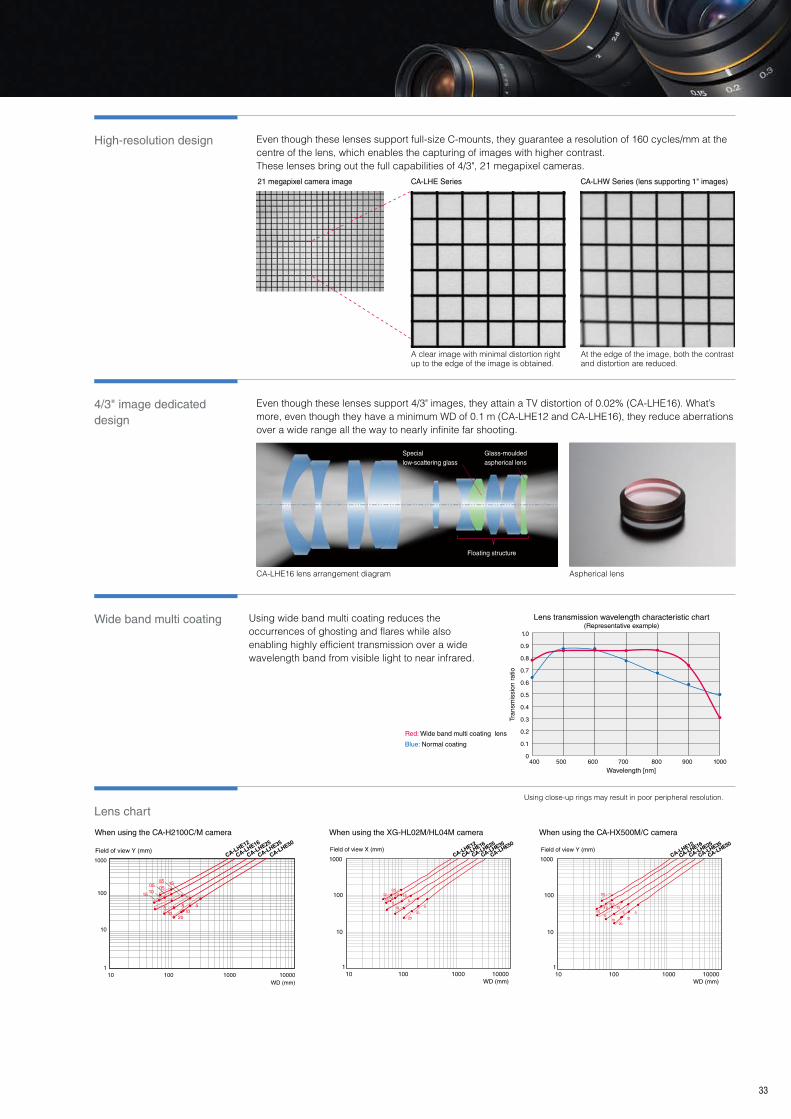
High-resolution design Even though these lenses support full-size C-mounts, they guarantee a resolution of 160 cycles/mm at the centre of the lens, which enables the capturing of images with higher contrast�These lenses bring out the full capabilities of 4/3", 21 megapixel cameras�
4/3" image dedicated design
Even though these lenses support 4/3" images, they attain a TV distortion of 0�02% (CA-LHE16)� What’s more, even though they have a minimum WD of 0�1 m (CA-LHE12 and CA-LHE16), they reduce aberrations over a wide range all the way to nearly infinite far shooting�
Wide band multi coating
Lens chart
33
10000100010010
CA-LH
E12
CA-LH
E16
CA-LH
E25
CA-LH
E35
CA-LH
E50
101020
555
1.5
1.01.5
0.50.50.5
WD (mm)
1000
100
10
1
Field of view Y (mm)1000
100
10
1100010010 10000
CA-LH
E12
CA-LH
E16
CA-LH
E25
CA-LH
E35
CA-LH
E50
20
1010 5
55
1.51.51.0
1.0 0.50.5
Field of view X (mm)
WD (mm)
1000
100
10
1100010010 10000
aaa
CA-LH
E12
CA-LH
E16
CA-LH
E25
CA-LH
E35
CA-LH
E50Field of view Y (mm)
WD (mm)
0.5
0.51.0
1.51.5
55 5
10 10
20
Using wide band multi coating reduces the occurrences of ghosting and flares while also enabling highly efficient transmission over a wide wavelength band from visible light to near infrared�
When using the CA-H2100C/M camera When using the XG-HL02M/HL04M camera When using the CA-HX500M/C camera
Using close-up rings may result in poor peripheral resolution�
A clear image with minimal distortion right up to the edge of the image is obtained�
At the edge of the image, both the contrast and distortion are reduced�
CA-LHW Series (lens supporting 1" images)21 megapixel camera image CA-LHE Series
CA-LHE16 lens arrangement diagram Aspherical lens
Red: Wide band multi coating lens
Blue: Normal coating
Lens transmission wavelength characteristic chart (Representative example)
Tran
smis
sion
rat
io
Wavelength [nm]
1.0
0.9
0.8
0.7
0.6
0.5
0.4
0.3
0.2
0.1
0400 500 600 700 800 900 1000
Special low-scattering glass
Floating structure
Glass-moulded aspherical lens
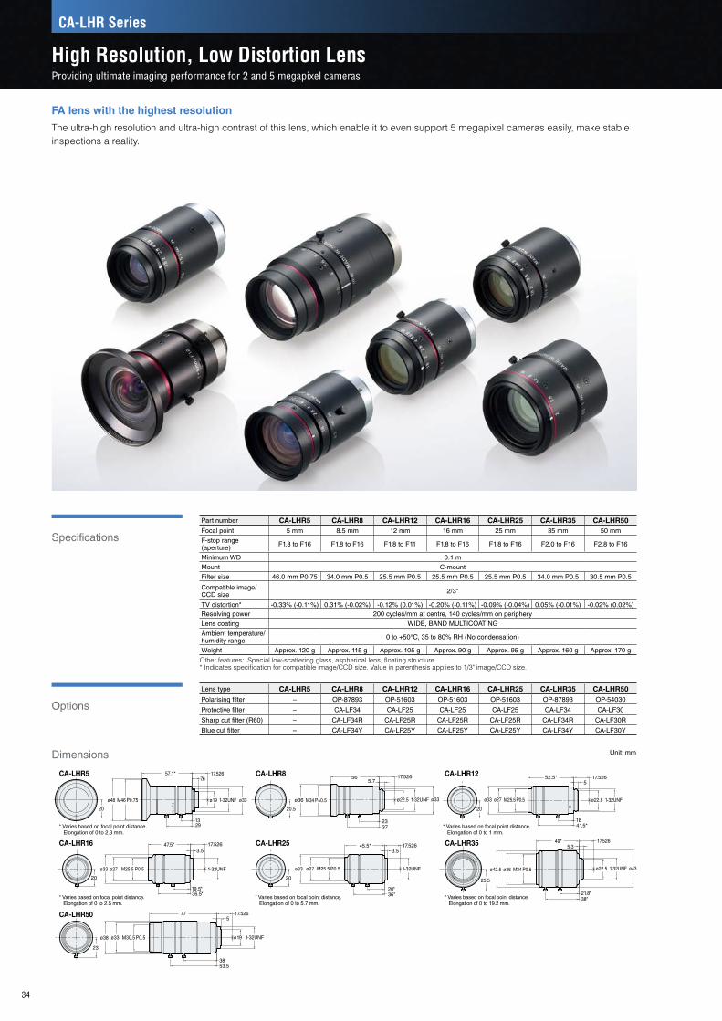
Specifications
Options
34
* Varies based on focal point distance. Elongation of 0 to 2.3 mm.
* Varies based on focal point distance. Elongation of 0 to 2.5 mm.
* Varies based on focal point distance. Elongation of 0 to 5.7 mm.
* Varies based on focal point distance. Elongation of 0 to 19.2 mm.
* Varies based on focal point distance. Elongation of 0 to 1 mm.
f=5m
m/F
1.8
CA-LHR57.6
57.1* 17.526
1329
1-32UNF
1-32UNF
1-32UNF
1-32UNF
1-32UNF
1-32UNF
1-32UNF
ø48 ø19 ø33 ø33M46 P0.75
20
ø33
20
ø22.8M25.5 P0.5ø27
41.5*18
52.5*5
17.526CA-LHR12
25.5
38*21.8*
ø43
49*5.3
M34 P0.5ø42.5 ø36
17.526
ø22.5
CA-LHR35
19.5*36.5*
20
CA-LHR163.5
17.52647.5*
ø27ø33 M25.5 P0.5
20
17.5263.5
ø33 M25.5 P0.5ø27
20*
45.5*
36*
CA-LHR25
ø36
20.5
56 17.526
2337
M34 P=0.5 ø22.5
5.7CA-LHR8
77
53.538
M30.5 P0.5ø38 ø33
17.5265
ø19
CA-LHR50
23
Part number CA-LHR5 CA-LHR8 CA-LHR12 CA-LHR16 CA-LHR25 CA-LHR35 CA-LHR50Focal point 5 mm 8.5 mm 12 mm 16 mm 25 mm 35 mm 50 mm
F-stop range (aperture) F1.8 to F16 F1.8 to F16 F1.8 to F11 F1.8 to F16 F1.8 to F16 F2.0 to F16 F2.8 to F16
Minimum WD 0.1 mMount C-mountFilter size 46.0 mm P0.75 34.0 mm P0.5 25.5 mm P0.5 25.5 mm P0.5 25.5 mm P0.5 34.0 mm P0.5 30.5 mm P0.5
Compatible image/CCD size 2/3"
TV distortion* -0.33% (-0.11%) 0.31% ( -0.02%) -0.12% ( 0.01%) -0.20% (-0.11%) -0.09% ( -0.04%) 0.05% (-0.01%) -0.02% (0.02%)Resolving power 200 cycles/mm at centre, 140 cycles/mm on peripheryLens coating WIDE, BAND MULTICOATING
Ambient temperature/humidity range 0 to +50°C, 35 to 80% RH (No condensation)
Weight Approx. 120 g Approx. 115 g Approx. 105 g Approx. 90 g Approx. 95 g Approx. 160 g Approx. 170 g
Other features: Special low-scattering glass, aspherical lens, floating structure* Indicates specification for compatible image/CCD size� Value in parenthesis applies to 1/3" image/CCD size�
Lens type CA-LHR5 CA-LHR8 CA-LHR12 CA-LHR16 CA-LHR25 CA-LHR35 CA-LHR50Polarising filter – OP-87893 OP-51603 OP-51603 OP-51603 OP-87893 OP-54030
Protective filter – CA-LF34 CA-LF25 CA-LF25 CA-LF25 CA-LF34 CA-LF30
Sharp cut filter (R60) – CA-LF34R CA-LF25R CA-LF25R CA-LF25R CA-LF34R CA-LF30R
Blue cut filter – CA-LF34Y CA-LF25Y CA-LF25Y CA-LF25Y CA-LF34Y CA-LF30Y
Dimensions Unit: mm
FA lens with the highest resolution
The ultra-high resolution and ultra-high contrast of this lens, which enable it to even support 5 megapixel cameras easily, make stable inspections a reality�
CA-LHR Series
High Resolution, Low Distortion LensProviding ultimate imaging performance for 2 and 5 megapixel cameras

Special optical design and construction
The CA-LHR Series provides a resolving power of 200 cycles/mm at the centre of the lens and 140 cycles/mm on the periphery of the lens, which is twice or higher the performance of conventional high-resolution lenses� This makes it possible to obtain high-contrast images and perform stable inspections of the dimensions and appearance of targets�
Minimum working distance By using special low-scattering glass, we have achieved a working distance of 0�1 m for all models� This makes it possible to use the lens to the extent of its capabilities over a wide range without needing a close-up ring�
Lens chart
35
When using the CA-HX200M/C cameraWhen using the xx-H500M/C camera When using the xx-(H)200M/C camera
Resolution at the edge of the image area
Resolution at centre
CA-LHR Series
CA-LHR Series
Conventional Lens
Conventional Lens
The CA-LHR Series can capture images at high resolution across the whole image area�
An image with high resolution from the centre to the periphery of the image is obtained� Because the WD can be set to 100 mm without using a close-up ring, the lens is used to the extent of its capabilities�
The same resolution is obtained in the centre of the image, but the resolution is worse in the periphery of the image due to the effect of the close-up ring�
1000
100
10
1100010010 10000
CA-LH
R12
CA-LH
R8
CA-LH
R5
CA-LH
R16
CA-LH
R25
CA-LH
R35
CA-LH
R50
Field of view Y (mm)
WD (mm)
0.5
1.5 1.5
510
1020
1.0 1.0
0.50.5
20
1.0
1.51.51.5
5
1010
5
1.00.5
0.5
0.5
1000
100
10
1100010010 10000
CA-LH
R5
CA-LH
R8
CA-LH
R12
CA-LH
R16
CA-LH
R25
CA-LH
R35
CA-LH
R50
Field of view Y (mm)
WD (mm)
1.5
5
20
0.5
1.01.5
1.5
510
10
0.5
1.00.5
1000
100
10
1100010010 10000
CA-LH
R5
CA-LH
R8
CA-LH
R12
CA-LH
R16
CA-LH
R25
CA-LH
R35
CA-LH
R50
Field of view Y (mm)
WD (mm)
Using an aspherical lens, floating structure and low-dispersion glass, the CA-LHR Series can reduce image aberration to a minimum�
Using close-up rings may result in poor peripheral resolution�
5 megapixel camera image CA-LHR35, WD: 100 mm, no close-up ring CA-LHE35 + close-up ring: 22 mm, WD: 100 mm

Specifications
Options
Minimum working distance When compared to standard lenses the CA-LH Series has a significantly reduced minimum working distance� This means that one lens can easily accommodate for a range of different target heights without the need for close up rings or troublesome change overs�
Lowest distortion in its class
High performance
36
With an original optical design, the CA-LH Series drastically eliminates distortion� This is of great significance when using machine vision for dimensional measurement or other applications that need high precision and performance� Distortion is reduced to 0�01% or less�** With CA-LH50 on 1/3" CCD size
Using a floating mechanism that moves the front lens and rear lens individually, the CA-LH Series provides consistent optical performance across a wide range of working distances to maintain a sharp image� Contrast is also improved in comparison with standard lenses� Even targets with low contrast differences can be resolved effectively without components being blended together�
Comparison of distortion
Comparison of magnified
images
Standard Lens CA-LH
CA-LHStandard Lens
Part number CA-LH4 CA-LH8 CA-LH12 CA-LH16 CA-LH25 CA-LH35 CA-LH50 CA-LH75Focal point 4.4 mm 8 mm 12 mm 16 mm 25 mm 35 mm 50 mm 75 mmF-stop range (aperture) F1.6 to F16 F1.4 to F16 F1.4 to F16 F1.4 to F16 F1.4 to F16 F2.0 to F16 F2.8 to F22 F2.5 to F22Minimum WD 0.1 m 0.1 m 0.15 m 0.2 m 0.2 m 0.2 m 0.2 m 1.2 mMount C-mountFilter size 43.0 mm P0.75 27.0 mm P0.5 27.0 mm P0.5 25.5 mm P0.5 27.0 mm P0.5 27.0 mm P0.5 27.0 mm P0.5 34.0 mm P0.5
Compatible image/CCD size 1/1.8" 2/3"
TV distortion* -0.2% (-0.13%) -0.6% (-0.28%) -0.07% ( -0.04%) -0.05% (-0.1%) -0.04% (-0.02%) -0.2% (-0.05%) -0.03% ( -0.01%) -0.1% ( -0.05%)Resolving power 100 cycles/mm at centre, 80 cycles/mm on periphery
Ambient temperature/humidity range 0 to +50°C, 35 to 80% RH (No condensation)
Weight Approx. 150 g Approx. 90 g Approx. 75 g Approx. 81 g Approx. 89 g Approx. 69 g Approx. 92 g Approx. 105 g
Other feature: Floating structure* Indicates specification for compatible image/CCD size� Value in parenthesis applies to 1/3” image/CCD size�
Lens type CA-LH4 CA-LH8 CA-LH12 CA-LH16 CA-LH25 CA-LH35 CA-LH50 CA-LH75Polarising filter OP-87894 OP-54029 OP-54029 OP-51603 OP-54029 OP-54029 OP-54029 OP-87893
Protective filter CA-LF43 CA-LF27 CA-LF27 CA-LF25 CA-LF27 CA-LF27 CA-LF27 CA-LF34
Sharp cut filter (R60) CA-LF43R CA-LF27R CA-LF27R CA-LF25R CA-LF27R CA-LF27R CA-LF27R CA-LF34R
Blue cut filter CA-LF43Y CA-LF27Y CA-LF27Y CA-LF25Y CA-LF27Y CA-LF27Y CA-LF27Y CA-LF34Y
Usable in a wide range of applications from measurements to appearance inspections
This high-resolution lens has the lowest distortion in its class�
CA-LH/LHxG Series
Low Distortion LensA lineup of vibration-resistant models

Specifications
Options
Strong vibration resistance together with ease of use
Fixing the focus with the red ring
37
The industry’s first fixed aperture replacement methodBy using fixed apertures, we have eliminated the problem of foreign contamination occurring due to the aperture drive section rubbing against another surface when the lens is subjected to vibrations� At the same time, the ability to replace aperture plates ensures support for different situations� Because the aperture values are fixed, it is easy to ensure that multiple units all use the same F-stop�
After adjusting the lens extending amount, use the red ring to fix the focus� The construction of this fixing section differs from the pin-point operation of a screw and performs fixing with a wide area, which makes it difficult for looseness to occur� The sufficient focus adjustment width enables both a minimum working distance of 0�1 m and ease of use�
Replacement aperture plates
Fix the focus with the focus ring (the red ring).
Part number (vibration-resistant models) CA-LH8G CA-LH12G CA-LH16G CA-LH25G CA-LH35G CA-LH50G
Focal point 8 mm 12 mm 16 mm 25 mm 35 mm 50 mm
F-stop range (aperture)*2 F1.4/4/8/16 F2.0/4/8/16 F2.8/4/8/16
Minimum WD*3 0.1 m 0.15 m 0.2 m 0.2 m 0.2 m 0.2 m
Mount C-mount
Filter size 27.0 mm P0.5
Compatible image/CCD size 2/3"
TV distortion*1 -0.6%(-0.28%)
-0.07%( -0.04%)
-0.05%(-0.1%)
-0.04%(-0.02%)
-0.2%(-0.05%)
-0.03%(-0.01%)
Resolving power 100 cycles/mm at centre, 80 cycles/mm on periphery
Ambient temperature/ humidity range 0 to +50°C, 35 to 80% RH (No condensation)
Weight Approx. 78 g Approx. 65 g Approx. 66 g Approx. 73 g Approx. 62 g Approx. 76 g
*1 This indicates the specification for the compatible image/CCD size� The value in parentheses applies to a 1/3" image/CCD size� *2 The vibration-resistant types are designed to have their apertures replaced� When shipped, the OPEN aperture is attached to the lens, so replace this with one of
the other included apertures (F4, F8, or F16) as necessary� To use the f-stop (aperture) in the OPEN mode, use the lens without removing the OPEN aperture� *3 Installing the lens at a distance from the target shorter than the minimum working distance listed in the specifications makes it very likely that the lens will drop out
due to vibrations� If the lens is installed in such a position, implement separate countermeasures to prevent the lens from dropping out�
Lens type CA-LHxGPolarising filter OP-54029
Protective filter CA-LF27
Sharp cut filter (R60) CA-LF27R
Blue cut filter CA-LF27Y * The filter sizes are the same for all CA-LHxG Series units�
A lineup of vibration-resistant models
Vibration-resistant models have been added to the CA-LH Series, which has the lowest distortion in its class� By thoroughly eliminating all screws from these lenses, we have eliminated the need to be concerned about the lens dropping out�

When using the xx-(H)200M/C camera When using the CA-HX048M/C camera (784 x 596) When using the xx-(H)035M/C camera
*焦点距離によって可変。伸び量 0~2.3mm。
*焦点距離によって可変。伸び量 0~2.5mm。
* Varies based on focal point distance. Elongation of 0 to 0.5 mm.
* Varies based on focal point distance. Elongation of 0 to 2.1 mm.
* Varies based on focal point distance. Elongation of 0 to 17.4 mm.
* Varies based on focal point distance. Elongation of 0 to 0.6 mm.
* Varies based on focal point distance. Elongation of 0 to 4.4 mm.
* Varies based on focal point distance. Elongation of 0 to 1 mm.
* Varies based on focal point distance. Elongation of 0 to 10 mm.
*焦点距離によって可変。伸び量 0~5.7mm。*焦点距離によって可変。伸び量 0~19.2mm。
*焦点距離によって可変。伸び量 0~1mm。
f=5m
m/F
1.8
CA-LHR57.6
57.1* 17.526
1329
1-32UNF
1-32UNF
1-32UNF
1-32UNF
1-32UNF
1-32UNF
1-32UNF
ø48 ø19 ø33 ø33M46 P0.75
20
ø33
20
ø22.8M25.5 P0.5ø27
41.5*18
52.5*5
17.526CA-LHR12
25.5
38*21.8*
ø43
49*5.3
M34 P0.5ø42.5 ø36
17.526
ø22.5
CA-LHR35
19.5*36.5*
20
CA-LHR163.5
17.52647.5*
ø27ø33 M25.5 P0.5
20
17.5263.5
ø33 M25.5 P0.5ø27
20*
45.5*
36*
CA-LHR25
ø36
20.5
56 17.526
2337
M34 P=0.5 ø22.5
5.7
CA-LHR8
77
53.538
M30.5 P0.5ø38 ø33
17.5265
ø19
CA-LHR50
23
20
17.5267.5 (Max.)23.6*
11
1-32UNFø22.5
aa
20
18.326.8*
aa
ø34 ø28.5 M27 P0.5
41.6*
39.5*
17.526
8.46
ø21 1-32UNF
1-32UNF
20.5
17.52641.5* 3.5
29*
aa aa
ø34 ø28.5 M27 P0.5
55*
ø33.5 M27 P0.5ø28.5
146°80°
M1.7
ø45 43P0.75
37.5
ø32
1-32UNF
2 Aperture lock screw3
Focus lock screw
17.526
CV-L3
0.5 1 5 4 4 22 4
1-32UNF
1-32UNF
1-32UNF
10
OP-51612
37°
Index line
ø32.8ø32
30.5P0.5
17.526
A B
A B
1.4 Engravedposition
1912.8
374
A-AB-B
ø29.4ø32
1-32UNF
90°
Aperture lock screwFocus lock screw
CV-L6
B
3 x M1.7
3 x M1.7
ø3230.5P0.5
120°
120° 95°
105°
A
A B
Aperture lock screw
Focus lock screw 12.4
37 17.526
1-32UNF
1.8 Engravedposition
4
5.5
A-A B-BIndex line
CV-L50
a aa
aa
CV-L25 CV-L35
20
17.526
1-32UNFø22.5
4.9 (Max.)21.8*11
aa 36.5*
ø33.5 ø27 M25.5 P0.5
25
31.5*6.9
1-32UNFø15.5ø45 M43 P0.75
57.5* 17.5264 5.1
2.24
ø28.5ø34 1-32UNFø22
37* 17.526
16.525*
M27P0.5
20.5
M27 P0.5 ø29
28.6*16*
36.5* 17.5263.5
1-32UNFø34
21
4.054
M27 P0.5
28.5 17.526
ø15.5 1-32UNFø28.5
18.25
3.821
ø30
19.5
ø32 M30.5 P0.5
34
1-32UNFø21.6
17.52636.5
5.822.5
ø29.3
24.5
4
7.5
4.417.526
ø30A B
A B
A-AB-B
Index line1.6 Engravedposition
27 P0.5
37°
ø30
12.1
ø161-32UNF
Focus lock screw Aperture lock screw
90°
CV-L16
ø36 ø32ø21.5
* Varies based on focal point distance. Elongation of 0 to 5 mm.
1-32 UNF
M34 P=0.5
51* 17.5264 3
5.8
19.5
22.5*
CA-LH12G
ø30ø22 ø33M27
(P=0.5)
Focus lock screw
1-32 UNFC-mount
17.526
5.2 (Max.)37*
* Varies based on focal point distance. Elongation of 0 to 1.0 mm.
CA-LH16G
ø30 ø33ø22.5M27(P=0.5)
Focus lock screw
1-32 UNFC-mount
17.526
4.86 (Max.)36.5*
* Varies based on focal point distance. Elongation of 0 to 2.1 mm.
CA-LH25G
ø30ø22.5 ø33M27
(P=0.5)
Focus lock screw
1-32 UNFC-mount
17.526
7.4 (Max.)39.5*
* Varies based on focal point distance. Elongation of 0 to 4.5 mm.
CA-LH35G
ø30.5 ø33M27(P=0.5)
Focus lock screw
1-32 UNFC-mount
17.526
38.8* 4
* Varies based on focal point distance. Elongation of 0 to 6.5 mm.
CA-LH50G
ø30ø33M27
(P=0.5)
Focus lock screw
1-32 UNFC-mount
17.526
456.2*
* Varies based on focal point distance. Elongation of 0 to 15.8 mm.
CA-LH8G
ø30 ø21 ø33M27(P=0.5)
C-mount1-32 UNF
Focus lock screw
41.6* 8.5 (Max.)
17.526* Varies based on focal point distance. Elongation of 0 to 0.6 mm.
Lens chart
38
100010010 10000
1000
100
10
1
CA-LH
4
CA-LH
8
CA-LH
12
CA-LH
16
CA-LH
25
CA-LH
35
CA-LH
50
CA-LH
75
100
6060
4040
30
30
20
2020
20
15
15
10
101010
1.01.0
1.05
55
1.5
0.50.50.5
0.5
1.51.5
1.55
5
Field of view Y (mm)
WD (mm)
0.5
0.5
1.51.5
1.5
1.5
5
5
5
5
2020
20
2015
40
4030
6060
100
1510 10
10
10
30
51.0
1.0
1.0
0.50.5
1000
100
10
1100010010 10000
CA-LH
12
CA-LH
8
CA-LH
4
CA-LH
16
CA-LH
25
CA-LH
35
CA-LH
50
CA-LH
75
Field of view Y (mm)
WD (mm)
Field of view Y (mm)
WD (mm)
CA-LH
4CA
-LH8
CA-LH
12
CA-LH
16
CA-LH
25
CA-LH
35
CA-LH
50
CA-LH
75
100010010 10000
1000
100
10
1
1.5
5
1.0 1.0 1.5
1.00.5 0.50.5
5.0
2015
10
5.05
6040
20
10
1.51.50.5
2015
10
5
100
6040
30
30
20
10
CA-LH dimensions
CA-LHxG dimensions
CA-LH4
CA-LH16
CA-LH8G
CA-LH25G
CA-LH50
CA-LH8
CA-LH25
CA-LH12G
CA-LH35G
CA-LH75
CA-LH12
CA-LH35
CA-LH16G
CA-LH50G
Using close-up rings may result in poor peripheral resolution�
Unit: mm
Unit: mm
CA-LH/LHxG Series
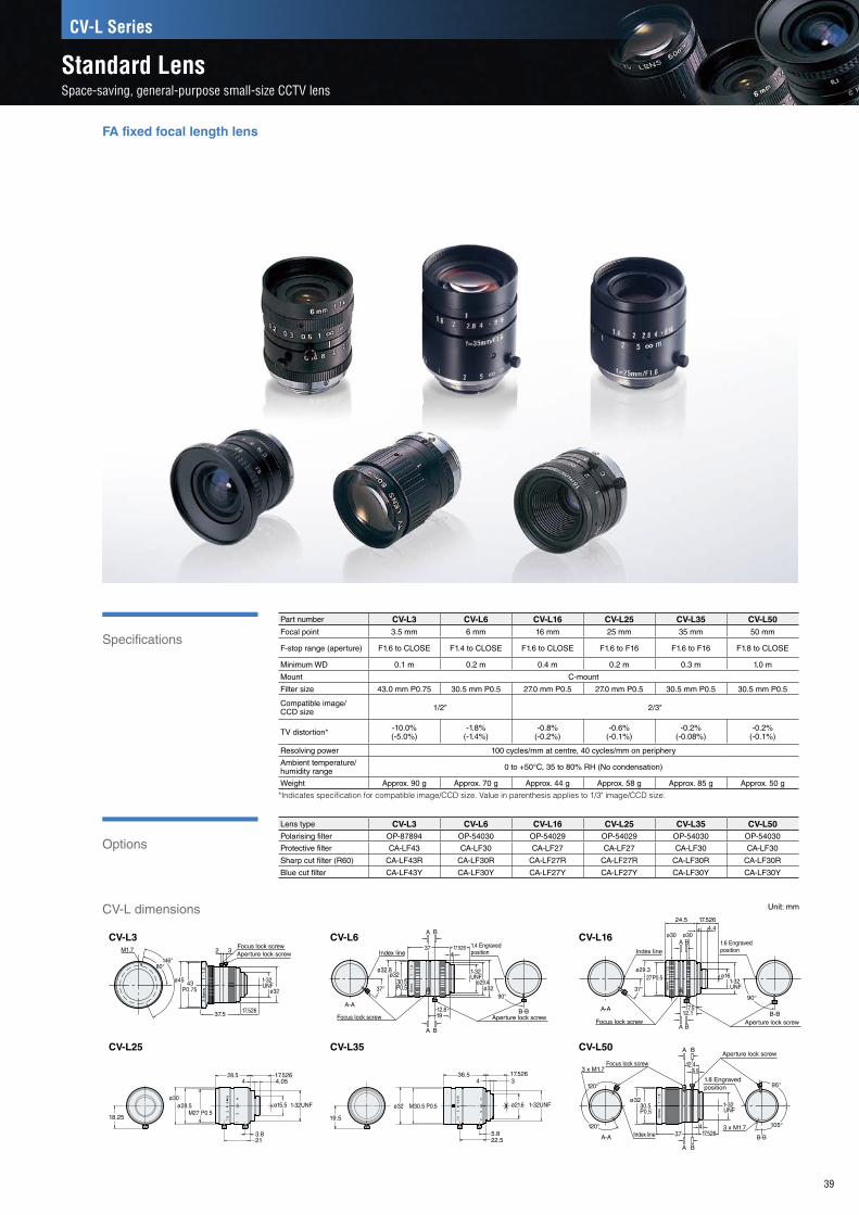
*焦点距離によって可変。伸び量 0~2.3mm。
*焦点距離によって可変。伸び量 0~2.5mm。
* Varies based on focal point distance. Elongation of 0 to 0.5 mm.
* Varies based on focal point distance. Elongation of 0 to 2.1 mm.
* Varies based on focal point distance. Elongation of 0 to 17.4 mm.
* Varies based on focal point distance. Elongation of 0 to 0.6 mm.
* Varies based on focal point distance. Elongation of 0 to 4.4 mm.
* Varies based on focal point distance. Elongation of 0 to 1 mm.
* Varies based on focal point distance. Elongation of 0 to 10 mm.
*焦点距離によって可変。伸び量 0~5.7mm。*焦点距離によって可変。伸び量 0~19.2mm。
*焦点距離によって可変。伸び量 0~1mm。
f=5m
m/F
1.8
CA-LHR57.6
57.1* 17.526
1329
1-32UNF
1-32UNF
1-32UNF
1-32UNF
1-32UNF
1-32UNF
1-32UNF
ø48 ø19 ø33 ø33M46 P0.75
20
ø33
20
ø22.8M25.5 P0.5ø27
41.5*18
52.5*5
17.526CA-LHR12
25.5
38*21.8*
ø43
49*5.3
M34 P0.5ø42.5 ø36
17.526
ø22.5
CA-LHR35
19.5*36.5*
20
CA-LHR163.5
17.52647.5*
ø27ø33 M25.5 P0.5
20
17.5263.5
ø33 M25.5 P0.5ø27
20*
45.5*
36*
CA-LHR25
ø36
20.5
56 17.526
2337
M34 P=0.5 ø22.5
5.7
CA-LHR8
77
53.538
M30.5 P0.5ø38 ø33
17.5265
ø19
CA-LHR50
23
20
17.5267.5 (Max.)23.6*
11
1-32UNFø22.5
aa
20
18.326.8*
aa
ø34 ø28.5 M27 P0.5
41.6*
39.5*
17.526
8.46
ø21 1-32UNF
1-32UNF
20.5
17.52641.5* 3.5
29*
aa aa
ø34 ø28.5 M27 P0.5
55*
ø33.5 M27 P0.5ø28.5
146°80°
M1.7
ø45 43P0.75
37.5
ø32
1-32UNF
2 Aperture lock screw3
Focus lock screw
17.526
CV-L3
0.5 1 5 4 4 22 4
1-32UNF
1-32UNF
1-32UNF
10
OP-51612
37°
Index line
ø32.8ø32
30.5P0.5
17.526
A B
A B
1.4 Engravedposition
1912.8
374
A-AB-B
ø29.4ø32
1-32UNF
90°
Aperture lock screwFocus lock screw
CV-L6
B
3 x M1.7
3 x M1.7
ø3230.5P0.5
120°
120° 95°
105°
A
A B
Aperture lock screw
Focus lock screw 12.4
37 17.526
1-32UNF
1.8 Engravedposition
4
5.5
A-A B-BIndex line
CV-L50
a aa
aa
CV-L25 CV-L35
20
17.526
1-32UNFø22.5
4.9 (Max.)21.8*11
aa 36.5*
ø33.5 ø27 M25.5 P0.5
25
31.5*6.9
1-32UNFø15.5ø45 M43 P0.75
57.5* 17.5264 5.1
2.24
ø28.5ø34 1-32UNFø22
37* 17.526
16.525*
M27P0.5
20.5
M27 P0.5 ø29
28.6*16*
36.5* 17.5263.5
1-32UNFø34
21
4.054
M27 P0.5
28.5 17.526
ø15.5 1-32UNFø28.5
18.25
3.821
ø30
19.5
ø32 M30.5 P0.5
34
1-32UNFø21.6
17.52636.5
5.822.5
ø29.3
24.5
4
7.5
4.417.526
ø30A B
A B
A-AB-B
Index line1.6 Engravedposition
27 P0.5
37°
ø30
12.1
ø161-32UNF
Focus lock screw Aperture lock screw
90°
CV-L16
ø36 ø32ø21.5
* Varies based on focal point distance. Elongation of 0 to 5 mm.
1-32 UNF
M34 P=0.5
51* 17.5264 3
5.8
19.5
22.5*
Specifications
Options
39
FA fixed focal length lens
Part number CV-L3 CV-L6 CV-L16 CV-L25 CV-L35 CV-L50Focal point 3.5 mm 6 mm 16 mm 25 mm 35 mm 50 mm
F-stop range (aperture) F1.6 to CLOSE F1.4 to CLOSE F1.6 to CLOSE F1.6 to F16 F1.6 to F16 F1.8 to CLOSE
Minimum WD 0.1 m 0.2 m 0.4 m 0.2 m 0.3 m 1.0 m
Mount C-mount
Filter size 43.0 mm P0.75 30.5 mm P0.5 27.0 mm P0.5 27.0 mm P0.5 30.5 mm P0.5 30.5 mm P0.5
Compatible image/ CCD size 1/2" 2/3"
TV distortion* -10.0%(-5.0%)
-1.8%(-1.4%)
-0.8%(-0.2%)
-0.6%(-0.1%)
-0.2%(-0.08%)
-0.2%(-0.1%)
Resolving power 100 cycles/mm at centre, 40 cycles/mm on periphery
Ambient temperature/humidity range 0 to +50°C, 35 to 80% RH (No condensation)
Weight Approx. 90 g Approx. 70 g Approx. 44 g Approx. 58 g Approx. 85 g Approx. 50 g
*Indicates specification for compatible image/CCD size� Value in parenthesis applies to 1/3" image/CCD size�
Lens type CV-L3 CV-L6 CV-L16 CV-L25 CV-L35 CV-L50Polarising filter OP-87894 OP-54030 OP-54029 OP-54029 OP-54030 OP-54030
Protective filter CA-LF43 CA-LF30 CA-LF27 CA-LF27 CA-LF30 CA-LF30
Sharp cut filter (R60) CA-LF43R CA-LF30R CA-LF27R CA-LF27R CA-LF30R CA-LF30R
Blue cut filter CA-LF43Y CA-LF30Y CA-LF27Y CA-LF27Y CA-LF30Y CA-LF30Y
CV-L dimensions
CV-L3
CV-L25
CV-L6
CV-L35
CV-L16
CV-L50
Unit: mm
CV-L Series
Standard LensSpace-saving, general-purpose small-size CCTV lens

Options
Part number CA-LM0210 CA-LML0210Optical magnification ×0.25 to ×1.0 ×0.25 to ×1.0Telecentricity — —
WD*3
(mm, at reference magnification)
×0.25 238 mm ×0.25 238 mm×0.50 137 mm ×0.50 137 mm×0.75 105 mm ×0.75 105 mm×1.0 88 mm ×1.0 88 mm
Compatible image/CCD size 1" 2"
Field of view (at reference magnification)
2/3" 6.6 × 8.8 mm to 26.4 × 35.2 mm 1" 9.6 × 12.8 mm to
38.4 × 51.2 mm14.3 mm line camera 14.3 to 57.3 mm 28.7 mm line camera 28.7 to 114.7 mm
1" 9.6 × 12.8 mm to 38.4 × 51.2 mm 2" 19.2 × 25.6 mm to
76.8 × 102.4 mmF-stop range (aperture) F6 to F64 (F-stop: F2.8 to F32) F6 to F64 (F-stop: F2.8 to F32)
Depth of field*1
×0.25 10.24 mm ×0.25 10.24 mm×0.50 2.56 mm ×0.50 2.56 mm×1.0 0.64 mm ×1.0 0.64 mm
TV distortion (Max.)
×0.25 -0.11% ×0.25 -0.10%×0.50 0.03% ×0.50 0.10%×1.0 0.01% ×1.0 -0.10%
Resolution (µm)*2
×0.25 16.8 µm ×0.25 16.8 µm×0.50 8.4 µm ×0.50 8.4 µm×1.0 4.2 µm ×1.0 4.2 µm
Mount C-mount Special mount (M40 P0.75)Filter size 46.0 mm P0.75 46.0 mm P0.75Ambient temperature/humidity range 0 to 50°C, 35% to 80% RH (No condensation)
Weight Approx. 640 g Approx. 650 g
*1 Depth of field applies to an F-stop of 16 and will vary depending on F-stop setting� The indicated depth of field is a theoretical value that assumes 1/2" CCD size and a horizontal resolution of 320 lines� (Circle of least confusion is 40 μm in the image)
*2 The smallest resolvable feature that can be detected using 550 nm wavelength light�*3 WD indicates a working distance at reference magnification� WD will vary depending on magnification
adjustment�Note: When installing the macro lens (CA-LMxx) to the line scan camera, make sure to secure the lens unit
with the dedicated mounting stand (OP-87337, sold separately) or an equivalent mount�
Part number OP-87319Camera side mount
Special mount (M40 P0.75)
Lens side mount Nikon F-mount
Weight Approx. 90 g
F-mount conversion adapter
Part number OP-87337Weight Approx. 980 g
Dedicated mounting stand for the macro lens
Specifications
Part number CA-LHW8 CA-LHW12 CA-LHW16 CA-LHW25 CA-LHW35 CA-LHW50 CA-LHL16 CA-LHL25 CA-LHL35Focal point 8 mm 12.5 mm 16 mm 25 mm 35 mm 50 mm 16 mm 25 mm 35 mm
F-stop*1 F1.4 to F16 F1.4 to F16 F1.4 to F16 F1.4 to F16 F1.4 to F16 F1.4 to F16 F2.8 to F32 F2.8 to F32 F2.8 to F32
Minimum WD 0.1 m 0.3 m 0.3 m 0.3 m 0.3 m 0.5 m 0.1 mMount C-mount Special mount (M40 P0.75)Filter size 55.0 mm P0.75 35.5 mm P0.5 35.5 mm P0.5 35.5 mm P0.5 35.5 mm P0.5 40.5 mm P0.5 77 mm P0.75 52 mm P0.75 46 mm P0.75
Compatible image/CCD size 1" 2"
TV distortion*2 -1.2%(-1.6%, -1%)
-1.58%(-1%, -0.6%)
-1.0%(-0.7%, -0.4%)
-1.0%(-0.5%, -0.3%)
-0.5%(-0.3%, -0.1%)
-0.05%(0.05%, 0.02%) -0.20% -0.06% -0.05%
Resolving power 120 cycles/mm at centre, 63 cycles/mm on periphery 100 cycles/mm at centre, 80 cycles/mm on periphery
Ambient temperature/humidity range 0 to 50°C, 35 to 80% RH (No condensation) 0 to 50°C, 35 to 80% RH (No condensation)
Weight Approx. 210 g Approx. 160 g Approx. 150 g Approx. 130 g Approx. 140 g Approx. 210 g Approx. 420 g Approx. 420 g Approx. 330 g
*1 When used with a line camera, an aperture of around F 2.8 is recommended. This improves the peripheral resolving power.
*2 Indicates specification for compatible image/CCD size. Value in parenthesis applies to 2/3" or 1/2" CCD size.
40
Lens for line scan cameras
In order to design this lens as one dedicated for use with C-mount line scan cameras, we have used our proprietary optical systems to eliminate the distortion that easily occurs during close-proximity image capturing�
CA-LHW/CA-LHL/CA-LM Series
High-resolution Lenses for Line Scan CamerasProvides optimal imaging performance with minimal distortion

CA-LHW8Max. 1.25
6.958
17.526
ø22.9 ø42ø57
1-32UNFC-mount
CA-LHW12
25.1
Max. 1.25 51.5 17.5265.3
ø42ø22.9ø38
ø43
1-32UNFC-mount
CA-LHW16
5.4
ø43
ø38ø42
417.52652.9Max. 1.25
25.11-32UNFC-mount
CA-LHW50
ø49
ø44ø47.5
17.5264
48Max. 6.4
281-32UNFC-mount
CA-LHL16
M77P=0.75
ø80M40P=0.75
ø45 ø47 ø50
17.52685.1
5(8.5)34.6
CA-LHL25
32.645.6
ø50ø47ø46ø45M40P=0.75
5(8.2)
17.52690.4
M52P=0.75
ø54
CA-LHL35
32.644.6
ø48
(82.6)(8.2)
5
17.526
ø45 ø46 ø47M46P=0.75
M40P=0.75
CA-LM0210
OP-87337 (Dedicated mounting stand for the macro lens)
CA-LML0210(8k line scan cameras)
10
3434
28.974±0.05 5
ø35
OP-87319 (F-mount adaptor for 8k line scan cameras)
ø59M40P=0.75
* Maximum outer diameter dimensions from the centre of the CA-LM0210/CA-LML0210 lens and including the screw head:Aperture side (tip side): 30.25 mm. Zoom side (camera side): 32.25 mm.
* Recommended stand fixing bolts: M5 hexagon socket head locking bolts, double SEMS 4 bolts with L= 20 mm or more(Insert the bolts into the base of the stand to fix it in place.)
* CA-LM(L)0210 only
112.9112.948.4
1015
17.526
4(7)
20.230
ø48 M46P=0.75
ø51.5ø52.5ø56 1-32UNFC-mount
ø30 ø50 ø53.5 ø551-32UNFC-mount
ø30 ø50 ø53.5 ø55
(142.4)(142.4)
48.4112.9112.9
5(8.5)17.526
1015
20.230
ø56 ø52.5 ø51.5 ø48 M46P=0.75
ø56 ø52.5 ø51.5 ø48 M46P=0.75
ø45 ø50 ø53.5 ø55M40P=0.75
ø45 ø50 ø53.5 ø55M40P=0.75
48.4
(142.4)
48.4
(142.4)
(30)(30)
58 37.6
6868
9494
7.6
(142.4)(142.4)Lens centre
Location of mounting screws for the stand main unit*
(50)(50)
79
34.75
79
34.75
141.1141.16262
CA-LHW25
25.1
Max. 5.42 43 17.5264.5
ø42ø38
ø43
1-32UNFC-mount
CA-LHW35
25.1
Max. 5.42 43 17.5264
ø42ø38
ø43
1-32UNFC-mount
Lens chart
x0.25
x0.5
x0.75
x1.0 CA-LML0210
1000
100
10
1100010010 10000WD (mm)
8192 pixels (When using the XG-HL08M)
Fie
ld o
f vie
w X
(m
m)
8k line scan camera
CA-LH
L16
CA-LH
L25
CA-LH
L35
1.01.0
0.50.5
51.5 1.5
x0.25
x0.5
x0.75
x1.0
CA-LM0210
1000
100
10
1100010010 10000WD (mm)
2048 pixels/4096 pixels(When using the XG-HL02M/XG-HL04M)
Fie
ld o
f vie
w X
(m
m)
2k/4k line scan camera
CA-LH
W8
CA-LH
W12
CA-LH
W16
CA-LH
W25
CA-LH
W35
CA-LH
W50
41
CA-LHW dimensions Unit: mm
CA-LHL dimensions (for 8k line scan cameras) Unit: mm
Macro lens for line scan cameras CA-LM dimensions Unit: mm
When using the CA-LHW Series 2k/4k line scan camera
When using the CA-LHL Series 8k line scan camera
2048 pixels/4096 pixels(When using the XG-HL02M/XG-HL04M)
8192 pixels (When using the XG-HL08M)
Using close-up rings may result in poor peripheral resolution�

VPR equipped With conventional telecentric macro lenses, the selections were limited and depended on the characteristic optical magnifications of the lenses� The VPR (Variable Pixel Resolution) mechanism not only makes it possible to select lenses intuitively according to the pixel resolution but also brings a level of freedom to the range over which optical magnification can be adjusted�* These lenses are designed with optical magnification to match 5 megapixels (3�45 μm/pixel) and 2 megapixels (4�4 μm/pixel)�
Ultra high-resolution design
These lenses have been designed with consistently high resolution not only in the centre of the image but on its periphery as well� Even with a unit cell size of 3�45 μm/pixel, every part of the screen exhibits high resolution and contrast�
Distortion free
42
All models have a TV distortion of 0�02% or lower� This reduces distortion to 0�25 pixels or less over the entire image even for a 5 megapixel camera� These lenses are the perfect choice for a wide range of applications from dimension measurement to alignment�
The entire screen is free of distortion, and high-resolution images can be obtained�
CA-LMHR
Even for the most detailed part of the chart, sufficient contrast between the white and black lines is obtained�
CA-LM
Because the resolution is insufficient, the contrast is extremely low, which makes it impossible to sufficiently recognise the edges�
One of the ideal forms of telecentric macro lenses
The distortion-free performance of this lens and its VPR (Variable Pixel Resolution) mechanism make it easy to capture ideal images�
CA-LMHR Series
Distortion-free, VPR-equipped, Telecentric Macro LensHigh-performance telecentric macro lens supporting 2/3" images and 5 megapixels

ø39.5 ø50
31.1
16.833.9
100.1
100.4* 17.5263.5
32.9
1-32 UNFC-mount
CA-LMHE0510
ø82
ø80
ø42ø39.5ø80
ø79ø64
47
417.526
93.510119.6*
24.549.5
5.513.5
C-mount1-32 UNF
ø42ø50
31.1
6.531
3.517.526
113.4
114*
44.8
1-32 UNFC-mount
ø44ø48
127*
126
17.5263.5
30.6
41.550.5
34.3
C-mount1-32 UNF
Part number CA-LMHR08 CA-LMHR13 CA-LMHR20
Pixel resolution*1
(US 3.5 μm: low magnification to US 4.4 μm: high magnification)
5 μm/pixel 3 μm/pixel 2 μm/pixel
Optical magnification x0.69 to x0.88 x1.15 to x1.47 x1.73 to x2.20
WD*2Low magnification 111.0 mm 111.6 mm 114.8 mm
High magnification 111.0 mm 111.6 mm 109.4 mm
Max. compatible image/CCD size 2/3"
Field of view
2/3"12.2 × 10.3 mm 7.3 × 6.2 mm 4.8 × 4.1 mm
Low magnification
1/1.8"8.0 × 6.0 mm 4.8 × 3.6 mm 3.2 × 2.4 mm
High magnification
F-stop range (aperture)
Low magnification 5.6 to 23 5.7 to 38 6.8 to 43
High magnification 7.1 to 29 7.3 to 49 8.7 to 55
Resolving power Centre/periphery: 120 cycles/mm
Resolution*3 5.4 μm 3.3 μm 2.6 μm
TV distortionLow magnification 0.005% 0.011% 0.001%
High magnification -0.001% -0.015% 0.011%
Depth of field*4Low magnification 2.689 mm 0.968 mm 0.428 mm
High magnification 1.653 mm 0.592 mm 0.264 mm
Mount C-mount
Ambient temperature/humidity range 0 to 50°C, 35 to 80% RH (No condensation)
Weight Approx. 285 g Approx. 330 g Approx. 410 g
*1 The pixel resolution is the field of view per pixel� This varies depending on the camera used� US = Unit cell size (size of 1 pixel)
*2 WD indicates the distance from the tip of the lens to the workpiece� Changing the magnification changes this distance�*3 The smallest resolvable feature able to be detected under 550 nm wavelength light�*4 The depth of field is a theoretical value calculated with an F-stop of 16 and a circle of least confusion of 40 μm� This varies depending on the
F-stop�* Depending on factors such as the installation orientation and the vibrations of the environment, consider reinforcing the installation such as by
implementing countermeasures to hold the lens in place� For information on the locations to hold the lens in place, see the installation examples�
* The above values were calculated according to optical design values� Actual values for individual lenses will differ according to precision of assembly�
Specifications
43
CA-LMHR08 CA-LMHR20CA-LMHR13
• Fix in place the areas marked as in the figure by using a method so that the tightening becomes uniform�• Fix in place both the camera and the lens�• If this product will be attached to a piece of equipment, ensure that this product is insulated from the equipment�• With this product, changing the magnification causes the lens to extend and retract� Therefore, fix the lens in place after the magnification has been set�
* Varies based on focal point distance� Elongation of 0 to 21�2 mm�
* Varies based on focal point distance� Elongation of 0 to 10�0 mm�
* Varies based on focal point distance� Elongation of 0 to 20�6 mm�
(The extension amount is at its maximum value when the magnification is at its maximum value�)
(The extension amount is at its maximum value when the magnification is at its maximum value�)
(The extension amount is at its maximum value when the magnification is at its maximum value�)
Dimensions Unit: mm

ø82
ø80
ø42ø39.5ø80
ø79ø64
47
417.526
93.510119.6*
24.549.5
5.513.5
C-mount1-32 UNF
Resolution comparison
120 lines are acquired both for the centre and periphery resolutions, which means that these lenses bring out the full capabilities of 4/3”, 21 megapixel cameras�These are the optimal lenses to use when applying telecentric lenses to line scan cameras�
Specifications
44
CA-LMHE0510
Part number CA-LMHE0510
Optical magnification 0.5x to 1.0x
WD*1
(at reference magnification)
x0.5 80.0 mm
x1.0 81.8 mm
Compatible image/CCD size 4/3" (ø23 mm)
Field of view(at reference magnification)
4/3" 36.8 × 27.6 mm to 18.4 × 13.8 mm
2/3" 17.6 × 13.2 mm to 8.8 × 6.6 mm
F-stop range (aperture) 5.0 to 32
Resolving power Centre/periphery: 120 cycles/mm
Resolution*3x0.5 6.7 μm
x1.0 3.4 μm
TV distortionx0.5 0.10%
x1.0 0.10%
Depth of field*2x0.5 5.12 mm
x1.0 1.28 mm
Mount C-mount
Ambient temperature/humidity range
0 to 50°C, 35 to 80% RH(No condensation)
Weight Approx. 1050 g
Even though the magnification is roughly the same, the resolution is insufficient due to the effect of the close-up ring, which means that contrast cannot be obtained�
Even the extremely detailed parts can be imaged with high contrast�
*1 WD indicates the distance from the tip of the lens to the workpiece� Changing the magnification changes this distance�*2 The depth of field is a theoretical value calculated with an F-stop of 16 and a circle of least confusion of 40 μm� This varies depending on the
F-stop�*3 The smallest resolvable feature able to be detected under 550 nm wavelength light� * Depending on factors such as the installation orientation and the vibrations of the environment, consider reinforcing the installation such as by
implementing countermeasures to hold the lens in place� For information on the locations to hold the lens in place, see the installation examples�
* The above values were calculated according to optical design values� Actual values for individual lenses will differ according to precision of assembly�
21 megapixel camera + CA-LMHE21 megapixel camera + CA-LHE + close-up ring
• Fix in place the areas marked as in the figure by using a method so that the tightening becomes uniform�
• Fix in place both the camera and the lens�
• If this product will be attached to a piece of equipment, ensure that this product is insulated from the equipment�
* Varies based on focal point distance� Elongation of 0 to 31�9 mm� (The extension amount is at its maximum value when the magnification is at its minimum value�)
Dimensions Unit: mm
Telecentric macro lens supporting 4/3" C-mounts
While it supports full-size, 4/3", ø23 mm C-mounts, this telecentric macro lens also makes high resolution a reality� Its magnification can be varied from x0�5 to x1, which makes it possible to use this lens as a general-purpose instrument in a wide variety of applications�
CA-LMHE Series
Variable-magnification Telecentric Macro Lens Supporting 4/3" ImagesA telecentric macro lens that fully enables the capabilities of 21 megapixel cameras

Why use telecentric lenses
(A comparison between
CA-LM0510 and CA-LH50)
Comparison chart of resolutions for a telecentric lens and standard resolution lens
Specifications
Options
45
Lens type CA-LM0510 CA-LM0307Polarising filter OP-54030 —Protective filter CA-LF30 —Sharp cut filter (R60) CA-LF30R CA-LF37RBlue cut filter CA-LF30Y CA-LF37Y
68(34.5)
41.2
(131.7) (48.3)*
70
6.7130.7
80 0.2
2560
68(34.5)
41.2
(131.7) (48.3)*
70
6.7130.7
80 0.2
2560
68(34.5)
41.2
(131.7) (48.3)*
70
6.7130.7
80 0.2
2560
Telecentric lens Standard lens
Telecentric lens Standard lens
CA-LH50(with close-up ring = 44 mm)
CA-LM0510(1.0x optical magnification)
CA-LH50(with close-up ring = 44 mm)
CA-LM0510(1.0x optical magnification)
Using a standard lens with multiple close up rings decreases resolution and contrast�
The telecentric lens maintains the correct image size despite the 4�5 mm height difference in the target (right to left)�
A standard lens is affected by the height change in the target� When the distance from the lens is short, the captured image size becomes large� When the distance from the lens is long, the captured image size becomes small�
A high quality image can be reproduced even when magnified�
Distance from target to camera
Close Far Close Far
Distance from target to camera
Part number CA-LM0510 CA-LM0307Optical magnification (Reference magnification) ×0.5 to ×1.0 ×0.3 to ×0.75
WD (at reference magnification)
×0.5 111 mm ×0.3 177.8 mm×1.0 78 mm ×0.75 97 mm
Compatible image/CCD size 2/3"
Field of view (at reference magnification)
1/3" 3.6 × 4.8 mm to 7.2 × 9.6 mm 4.8 × 6.4 mm to 12 × 16 mm1/2" 4.8 × 6.4 mm to 9.6 × 12.8 mm 6.4 × 8.5 mm to 16 × 21.3 mm2/3" 6.6 × 8.8 mm to 13.2 × 17.6 mm 8.8 × 11.7 mm to 22.0 × 29.3 mm
F-stop range (aperture) 5 to CLOSE (F-stop: 2.8 to CLOSE)
Depth of field×0.5 5.12 mm ×0.3 14.22 mm×1.0 1.28 mm ×0.75 2.27 mm
TV distortion (Max.)×0.5 -0.4% ×0.3 0.10%×1.0 -0.1% ×0.75 0.025%
Resolution (µm)×0.5 6.7 µm ×0.3 11.2 µm×1.0 3.4 µm ×0.75 4.5 µm
Mount C-mountAmbient temperature/humidity range 0 to 50°C, 80% RH (No condensation)Weight Approx. 220 g Approx. 345 g
OP-87524
* WD indicates a working distance at reference magnification� WD will vary depending on magnification adjustment�
* Depth of field applies to an F-stop of 16� Depth of field varies depending on F-stop setting� The indicated depth of field is a theoretical value that assumes 1/2" Image/CCD size and a horizontal resolution of 320 lines� (Circle of least confusion is 40 μm in the image)
* The smallest resolvable feature able to be detected under 550 nm wavelength light�
* The above values were calculated according to optical design values� Actual values for individual lenses will differ according to precision of assembly�
* Stand fixing bolts: M4 × L16 double SEMS (P4) (Insert the bolts into the base of the stand to fix it in place�)
CA-LM0307
ø30
ø39
.8ø
4029
.1
17.526131.7116.8113.2
50
2 x M2
ø48
ø41
.8ø
40.6
M37
.5 ×
0.5
3.5 C-mount
Telecentric Macro Lens Dedicated securing stand*CA-LM0307 only
Dimensions Unit: mm
* When producing tools for use in holding the lens in place, use a split mould or similar object to hold in place the ø38 mm part�
CA-LM0510
ø40
ø30ø40.8 24.35
ø42
ø32
17.526
M30.5 x 0.5ø33
C-mount
Aperturering
2 x M2 x 4.3 lock screw
Variablemagnificationring
3.5
90.543
93.7103.7
ø38
Variable-magnification telecentric macro lens
This is a compact, variable-magnification telecentric lens supporting 2/3" images, which means that it can be used not only in dimension measurements but also in a wide variety of applications including appearance inspections�
CA-LM Series
Variable-magnification Telecentric Macro Lens Supporting 2/3" ImagesThe optimal lens for up to 2 megapixel cameras
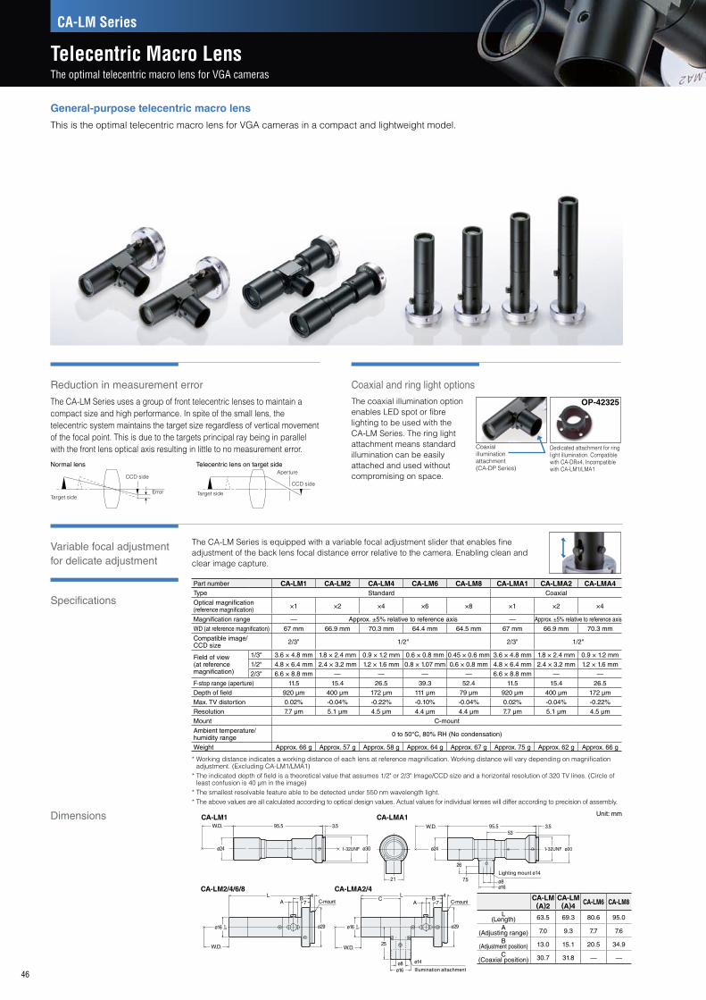
Coaxial and ring light optionsReduction in measurement error
Specifications
Variable focal adjustment for delicate adjustment
46
Part number CA-LM1 CA-LM2 CA-LM4 CA-LM6 CA-LM8 CA-LMA1 CA-LMA2 CA-LMA4Type Standard Coaxial
Optical magnification (reference magnification) ×1 ×2 ×4 ×6 ×8 ×1 ×2 ×4
Magnification range — Approx. ±5% relative to reference axis — Approx. ±5% relative to reference axisWD (at reference magnification) 67 mm 66.9 mm 70.3 mm 64.4 mm 64.5 mm 67 mm 66.9 mm 70.3 mm
Compatible image/ CCD size 2/3" 1/2" 2/3" 1/2"
Field of view(at reference magnification)
1/3" 3.6 × 4.8 mm 1.8 × 2.4 mm 0.9 × 1.2 mm 0.6 × 0.8 mm 0.45 × 0.6 mm 3.6 × 4.8 mm 1.8 × 2.4 mm 0.9 × 1.2 mm1/2" 4.8 × 6.4 mm 2.4 × 3.2 mm 1.2 × 1.6 mm 0.8 × 1.07 mm 0.6 × 0.8 mm 4.8 × 6.4 mm 2.4 × 3.2 mm 1.2 × 1.6 mm2/3" 6.6 × 8.8 mm — — — — 6.6 × 8.8 mm — —
F-stop range (aperture) 11.5 15.4 26.5 39.3 52.4 11.5 15.4 26.5Depth of field 920 µm 400 µm 172 µm 111 µm 79 µm 920 µm 400 µm 172 µmMax. TV distortion 0.02% -0.04% -0.22% -0.10% -0.04% 0.02% -0.04% -0.22%Resolution 7.7 µm 5.1 µm 4.5 µm 4.4 µm 4.4 µm 7.7 µm 5.1 µm 4.5 µmMount C-mount
Ambient temperature/humidity range 0 to 50°C, 80% RH (No condensation)
Weight Approx. 66 g Approx. 57 g Approx. 58 g Approx. 64 g Approx. 67 g Approx. 75 g Approx. 62 g Approx. 66 g
* Working distance indicates a working distance of each lens at reference magnification� Working distance will vary depending on magnification adjustment� (Excluding CA-LM1/LMA1)
* The indicated depth of field is a theoretical value that assumes 1/2" or 2/3" Image/CCD size and a horizontal resolution of 320 TV lines� (Circle of least confusion is 40 μm in the image)
* The smallest resolvable feature able to be detected under 550 nm wavelength light�* The above values are all calculated according to optical design values� Actual values for individual lenses will differ according to precision of assembly�
The coaxial illumination option enables LED spot or fibre lighting to be used with the CA-LM Series� The ring light attachment means standard illumination can be easily attached and used without compromising on space�
The CA-LM Series is equipped with a variable focal adjustment slider that enables fine adjustment of the back lens focal distance error relative to the camera� Enabling clean and clear image capture�
Coaxial illumination attachment (CA-DP Series)
Dedicated attachment for ring light illumination� Compatible with CA-DRx4, Incompatible with CA-LM1/LMA1
CA-LM2/4/6/8
W.D.
ø16 0-0.1
LA
B7
4C-mount
ø29
CA-LMA2/4
W.D.
C-mount
ø29
ø8 ø16
25
ø14
Illumination attachment
ø16 0-0.1
LA
B7
4C CA-LM
(A)2CA-LM
(A)4 CA-LM6 CA-LM8
L(Length) 63.5 69.3 80.6 95.0
A(Adjusting range) 7.0 9.3 7.7 7.6
B(Adjustment position) 13.0 15.1 20.5 34.9
C(Coaxial position) 30.7 31.8 — —
CA-LM1 CA-LMA1
ø24 ø24
ø8ø16
ø30
95.5 95.5
Lighting mount ø14
3.5 3.5
7.5
53
21
W.D. W.D.
1-32UNF 1-32UNF ø30
26
The CA-LM Series uses a group of front telecentric lenses to maintain a compact size and high performance� In spite of the small lens, the telecentric system maintains the target size regardless of vertical movement of the focal point� This is due to the targets principal ray being in parallel with the front lens optical axis resulting in little to no measurement error�
CCD sideCCD side
Aperture
Target sideTarget sideError
Normal lens Telecentric lens on target side
Dimensions Unit: mm
General-purpose telecentric macro lens
This is the optimal telecentric macro lens for VGA cameras in a compact and lightweight model�
CA-LM Series
Telecentric Macro LensThe optimal telecentric macro lens for VGA cameras
OP-42325

CA-LHS Series (CV-S200C/M XG-S200C/M dedicated lens)
CA-LS Series (CV-S035C/M XG-S035C/M dedicated lens)
47
2 megapixel Colour typeCV-S200C/XG-S200C
310000 pixel Colour typeCV-S035C/XG-S035C
2 megapixel Monochrome TypeCV-S200M/XG-S200M
310000 pixel Monochrome TypeCV-S035M/XG-S035M
Size comparison(CV-S035C/M vs CV-035C/M)
High-resolution lens
8 mmCA-LHS8
50 mmCA-LHS50
5 mmOP-66830
10 mmOP-66831 OP-66832
OP-66833
Close-up ring Polarising filter Side view attachment
4 mmCA-LS4
6 mmCA-LS6
16 mmCA-LS16
30 mmCA-LS30
5 mmOP-51500
10 mmOP-51501 OP-51502
OP-51503
Lens Close-up ring Polarising filter Side view attachment
12 x 12 mm body size (1/10 the size when compared to conventional model)
30 mm
CA-LHS8 CA-LHS16 CA-LHS25 CA-LHS50A 40.4 23.9 24.9 40.4B 28.6 17.9 18.6 27.1C 19.6 8.9 9.6 18.1
OP-66830 OP-66831A 5 10B 8 13C 17 17D M15.5 P=0.5 Female screwE M15.5 P=0.5 Male screw
LensCA-LHSx
Close-up ringOP-66830 (5 mm)OP-66831 (10 mm)
Polarising filterOP-66832
Side view attachmentOP-66833
(Unit: mm) (Unit: mm)
AB
C
12.5
9.5ø17
Special mountM15.5 P0.5 Female screw B
AE
C øC
Special mount
Special mount
3 x M1.6
ø17
Screw for securing lens
3.1
4.28
TargetLens insertion opening
3
ø25
24.9 2.6
27.49.5
15
23.3
TargetOptical axis(Internal optical path length = 25.8)
Lens insert depth: 5
31.83
15 30
2 x M2 d=8
ø17
4 x M1.6Screw for securing lens
CA-LS4 CA-LS6 CA-LS16 CA-LS30A 16.7 21.3 20.4 27B 11.5 15.9 10.2 13.2C 8.5 12.9 7.2 10.2
LensCA-LSx
OP-51500 OP-51501A 5 10B 8 13C 12 12D M10.5 P=0.5 Female screwE M10.5 P=0.5 Male screw
Close-up ringOP-51500 (5 mm) OP-51501 (10 mm)
A
D
B E
øCSpecial mount
Special mount
Polarising filterOP-51502
ø12
3 x M1.6Screw for securing lens
8
3
4.2
Target
Lens insertion opening
3
ø20
* Vignetting occurs in the images when this part is used in combination with the CA-LS4/LS6�
Side view attachmentOP-51503
13.7 2.8
14.9
d=5
213
1017.5
ø124 x M1.6Screw for securing lens
6.2514.7
9.7
TargetOptical axis(Internal optical path length = 15.3)
Lens insert depth: 4.5
12 mm
Super small camera dedicated lens
Even though these lenses have the same dimensions—ø12 mm and ø17 mm—of super small cameras, they still guarantee F-stop values starting at 2�0, which rivals the performance of normal lenses�
Dimensions Unit: mm
Dimensions Unit: mm
ABC
ø12
Special mount M10.5 P0.5 Female screw
10
7.2
CA-LS/CA-LHS Series
Super Small Camera Dedicated LensApplicable to 12 x 12 mm/17 x 17 mm compact camera
16 mmCA-LHS16
25 mmCA-LHS25

100
80
60
40
20
500 550 600 650 700 750 8000
R-60
Tran
smis
sion
rat
io T
(%
)
Wavelength (nm) (Reference data)
With sharp cut filterAmbient light is suppressed, which enables imaging�
With sharp cut filterThe influence of the fluorescent light can be reduced�
Without sharp cut filterThe fluorescent light is reflected by the metal surface�
Without sharp cut filterThe fluorescent light is refracted inside of the bottle, which makes inspections of the bottle opening difficult�
Sharp cut filters only allow light of
a wavelength longer than a certain
wavelength limit to pass�
Using these filters in combination
with red LED lights makes it
possible to capture images in
which the ambient light is
suppressed�
Sharp cut filter (R60)
Lineup
48
M25 P0.5 M27 P0.5 M30.5 P0.5 M34 P0.5 M37.5 P0.5 M40.5 P0.5 M43 P0.75
Protective filter High-transmission coating CA-LF25 CA-LF27 CA-LF30 CA-LF34 — — CA-LF43
Polarising filter High-transmission, polarising OP-51603 OP-54029 OP-54030 OP-87893 — — OP-87894
Sharp cut filter Transmitted wavelength: 600 nm or higher CA-LF25R CA-LF27R CA-LF30R CA-LF34R CA-LF37R CA-LF40R CA-LF43R
Blue cut filter Transmitted wavelength: 540 nm or higher CA-LF25Y CA-LF27Y CA-LF30Y CA-LF34Y CA-LF37Y CA-LF40Y CA-LF43Y
Polarising filter/Sharp cut filter (R60)/Blue cut filter/Protective filter
Filters support the stable detections of image processing used under a variety of conditions�
CA-LF Series
FiltersFilters support a variety of detections.
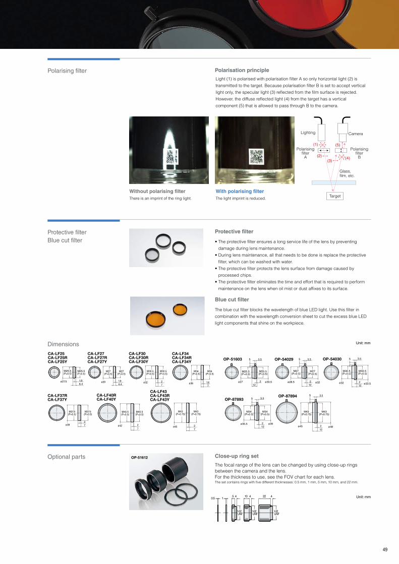
Protective filter Blue cut filter
Optional parts Close-up ring set
Protective filter
Blue cut filter
Polarising filter
49
OP-51612
0.5 15 10 224 4 4
1-32 UNF
1-32 UNF
1-32 UNF
CA-LF25CA-LF25RCA-LF25Y
6.41.9ø27.5
M25.5(P=0.5)
M25.5(P=0.5)
CA-LF30CA-LF30RCA-LF30Y
M30.5(P=0.5)
M30.5(P=0.5)
27
ø32
CA-LF27CA-LF27RCA-LF27Y
6.41.9
M27(P=0.5)
M27(P=0.5)
ø29
CA-LF34CA-LF34RCA-LF34Y
1.87
ø36
M34(P=0.5)
M34(P=0.5)
CA-LF37RCA-LF37Y
ø39
M37.5(P=0.5)
M37.5(P=0.5)
72
CA-LF40RCA-LF40Y
ø42
M40.5(P=0.5)
M40.5(P=0.5)
27
CA-LF43CA-LF43RCA-LF43Y
ø45
M43(P=0.75)
M43(P=0.75)
72
OP-87894
M43(P=0.75)
M43(P=0.75)
ø45 ø48
5 3.5
122
OP-51603
ø27 ø30.5
M25.5(P=0.5)
M25.5(P=0.5)
5
122
3.5 OP-54029
ø28.5 ø32
M27(P=0.5)
M27(P=0.5)
122
3.55 OP-54030
ø32
M30.5(P=0.5)
M30.5(P=0.5)
ø33.5
3.5
122
5
OP-87893
M34(P=0.5)
M34(P=0.5)
ø35.5 ø39
5
212
3.5
Polarisation principle
Without polarising filterThere is an imprint of the ring light�
With polarising filterThe light imprint is reduced�
Light (1) is polarised with polarisation filter A so only horizontal light (2) is
transmitted to the target� Because polarisation filter B is set to accept vertical
light only, the specular light (3) reflected from the film surface is rejected�
However, the diffuse reflected light (4) from the target has a vertical
component (5) that is allowed to pass through B to the camera�
Lighting
(1)
(2)(3)
(4)
(5)
Camera
Target
Glass,film, etc�
Polarisingfilter
B
Polarisingfilter
A
The focal range of the lens can be changed by using close-up rings between the camera and the lens�For the thickness to use, see the FOV chart for each lens�The set contains rings with five different thicknesses: 0�5 mm, 1 mm, 5 mm, 10 mm, and 22 mm�
• The protective filter ensures a long service life of the lens by preventing
damage during lens maintenance�
• During lens maintenance, all that needs to be done is replace the protective
filter, which can be washed with water�
• The protective filter protects the lens surface from damage caused by
processed chips�
• The protective filter eliminates the time and effort that is required to perform
maintenance on the lens when oil mist or dust affixes to its surface�
The blue cut filter blocks the wavelength of blue LED light� Use this filter in
combination with the wavelength conversion sheet to cut the excess blue LED
light components that shine on the workpiece�
Dimensions Unit: mm
Unit: mm
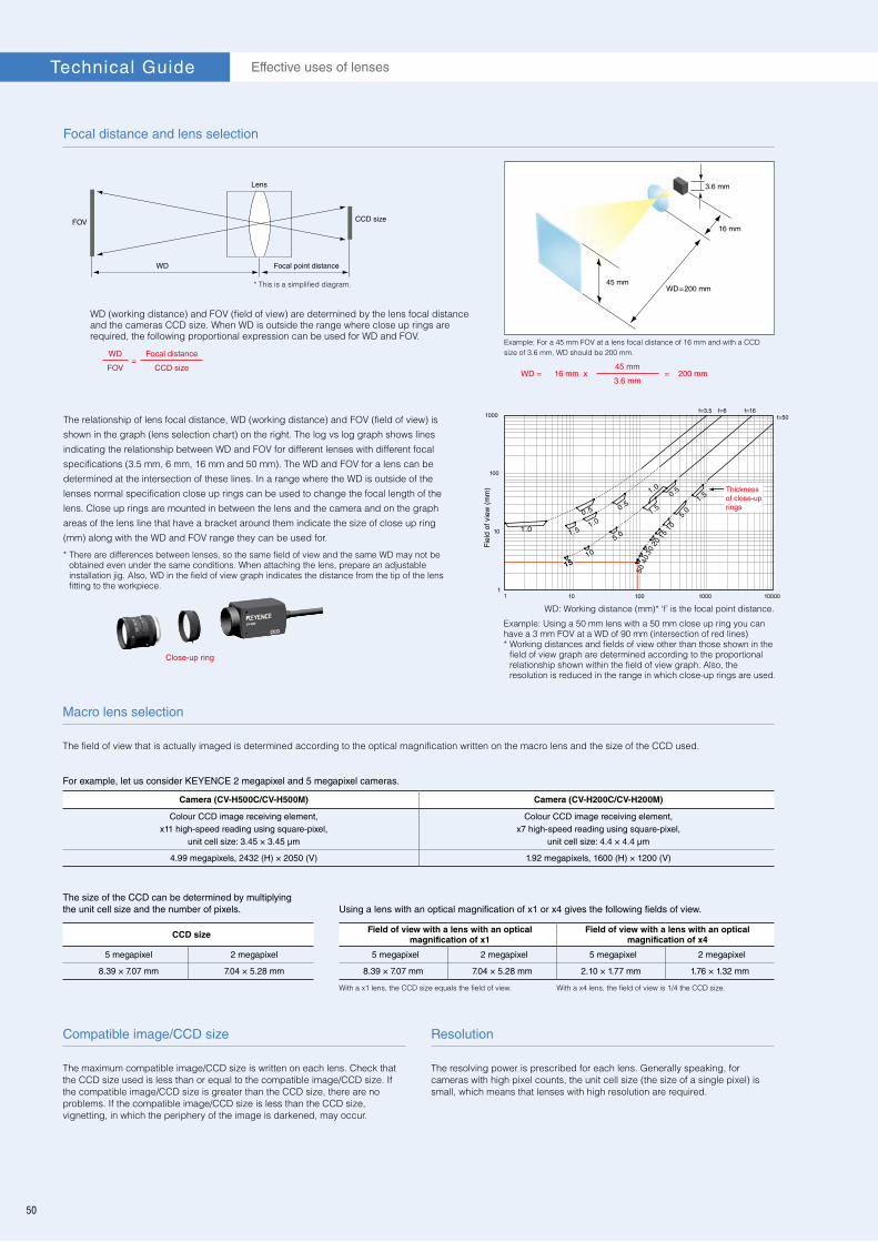
Focal distance and lens selection
The relationship of lens focal distance, WD (working distance) and FOV (field of view) is
shown in the graph (lens selection chart) on the right� The log vs log graph shows lines
indicating the relationship between WD and FOV for different lenses with different focal
specifications (3�5 mm, 6 mm, 16 mm and 50 mm)� The WD and FOV for a lens can be
determined at the intersection of these lines� In a range where the WD is outside of the
lenses normal specification close up rings can be used to change the focal length of the
lens� Close up rings are mounted in between the lens and the camera and on the graph
areas of the lens line that have a bracket around them indicate the size of close up ring
(mm) along with the WD and FOV range they can be used for�
Close-up ring
Example: For a 45 mm FOV at a lens focal distance of 16 mm and with a CCD size of 3�6 mm, WD should be 200 mm�
WD = 16 mm x45 mm
= 200 mm3.6 mm
45 mm
16 mm
3.6 mm
WD=200 mm
Example: Using a 50 mm lens with a 50 mm close up ring you can have a 3 mm FOV at a WD of 90 mm (intersection of red lines)* Working distances and fields of view other than those shown in the
field of view graph are determined according to the proportional relationship shown within the field of view graph� Also, the resolution is reduced in the range in which close-up rings are used�
WD (working distance) and FOV (field of view) are determined by the lens focal distance and the cameras CCD size� When WD is outside the range where close up rings are required, the following proportional expression can be used for WD and FOV�
WD=
Focal distance
FOV CCD size
* There are differences between lenses, so the same field of view and the same WD may not be obtained even under the same conditions� When attaching the lens, prepare an adjustable installation jig� Also, WD in the field of view graph indicates the distance from the tip of the lens fitting to the workpiece�
* This is a simplified diagram�
11
10
100010010
100
10000
1000 f=50f=16f=6f=3.5
WD: Working distance (mm)* ‘f’ is the focal point distance�
Thickness of close-up rings
Fie
ld o
f vie
w (
mm
)
Macro lens selection
ResolutionCompatible image/CCD size
The field of view that is actually imaged is determined according to the optical magnification written on the macro lens and the size of the CCD used�
For example, let us consider KEYENCE 2 megapixel and 5 megapixel cameras.
The size of the CCD can be determined by multiplying the unit cell size and the number of pixels. Using a lens with an optical magnification of x1 or x4 gives the following fields of view.
The resolving power is prescribed for each lens� Generally speaking, for cameras with high pixel counts, the unit cell size (the size of a single pixel) is small, which means that lenses with high resolution are required�
With a x1 lens, the CCD size equals the field of view�
Camera (CV-H500C/CV-H500M) Camera (CV-H200C/CV-H200M)
Colour CCD image receiving element, x11 high-speed reading using square-pixel,
unit cell size: 3.45 × 3.45 μm
Colour CCD image receiving element, x7 high-speed reading using square-pixel,
unit cell size: 4.4 × 4.4 μm
4.99 megapixels, 2432 (H) × 2050 (V) 1.92 megapixels, 1600 (H) × 1200 (V)
CCD size Field of view with a lens with an optical magnification of x1
Field of view with a lens with an optical magnification of x4
5 megapixel 2 megapixel 5 megapixel 2 megapixel 5 megapixel 2 megapixel
8.39 × 7.07 mm 7.04 × 5.28 mm 8.39 × 7.07 mm 7.04 × 5.28 mm 2.10 × 1.77 mm 1.76 × 1.32 mm
The maximum compatible image/CCD size is written on each lens� Check that the CCD size used is less than or equal to the compatible image/CCD size� If the compatible image/CCD size is greater than the CCD size, there are no problems� If the compatible image/CCD size is less than the CCD size, vignetting, in which the periphery of the image is darkened, may occur�
With a x4 lens, the field of view is 1/4 the CCD size�
50
Effective uses of lensesTechnical Guide
Lens
Focal point distance
CCD sizeFOV
WD

Aperture and depth of field
Lens resolution and resolving power
Relationship between depth of field and resolution
51
1) A lens with a shorter focal distance provides a larger depth of field�2) As the lens-to-target distance becomes greater, the depth of field becomes larger�
NOTE: When close-up rings and a macro lens are used, the depth of field is naturally reduced�
3) As the aperture is reduced, the depth of field becomes larger� NOTE: Even with the same lens, you can easily obtain focused images by increasing the illumination intensity with the aperture reduced�
Depth of field means the range where an image is kept in focus� As the depth of field becomes large, the lens provides higher tolerance against vertical movement and subsequently a more stable inspection�
When aperture is open (CA-LH25)
When aperture is reduced (CA-LH25)
Conditions to deepen depth of field
Rear
Depth of focus
Focal point
Depth of field
FrontLens
One line or line pair
The width of the white or black line is the resolution�
Camera
15 mm
Field of view
Ruler(3 mm)
45° incline
Not only are the detailed edges displayed more clearly but there is also sufficient contrast between the white and black parts� This lens has a variable aperture, so the balance between resolution and depth of field can be adjusted by reducing the aperture (increasing the F-stop)�
The edges are not clear and, in addition, the contrast is extremely low� However, the depth of field is deeper than that obtained with the lens on the left�
Comparison with a 5 megapixel, x2 optical magnification macro lens
Test chart
The number of pairs of white and black lines that appear to be separated per millimeter in the white/black chart of the
image surface is called the resolving power� Also, the minimum pitch with which two points that are separated by a
small amount can be visually distinguished is called the resolution� Normally, the resolution is used to refer to the target
object and the resolving power is used to refer to the image�
Lens with a depth of field of 0.13 mm and an F-stop of 6.8 (CA-LMHR20)
Lens with a depth of field of 0.4 mm and an F-stop of 15.4 (CA-LM2)
To easily see and calculate depth of field a ruler can be used on an inclined surface� Taking the two extreme points on the ruler (top and bottom) when the mark is last in focus gives the hypotenuse distance of a triangle� Knowing the incline of the surface means the depth can be calculated with a simple trig calculation�
Sin θ =Depth of field
Top ruler point - Bottom ruler point
Alternatively the height difference of the two points will also result in the same value�

Aspherical lens
Floating structure
Colour aberration
Generally, spherical lenses are used in standard lens design� If a machine vision lens is comprised of spherical surfaces only, aberrations can easily occur, resulting in blurred or curved images� On the other hand, the CA-LHR Series uses “aspherical lens”, whose surfaces have been designed in a combination of various curvatures� Aspherical designs reduce lens thickness, providing compact design suitable for machine vision environments, while suppressing aberrations at the same time�
The CA-LHE/LHR/LH Series lenses are comprised of up to 11 lenses grouped at the front or back of the lens� CA-LHE/LHR/LH Series has a floating mechanism that can move the front and rear groups of the internal lenses separately, so that several lenses can work together effectively� When the front group of lenses moves during focus adjustment, the rear group of lenses moves to an appropriate position for optimised distortion correction� Thus, the CA-LHE/LHR/LH Series ensure high performance by maintaining optimum positions for the lens groups whether the target focal point is near or far to the lens and camera�
When a lens is comprised of a combination of several optical glasses, colour aberration is inevitable� Colour aberration means a focus position difference due to wavelength� The refractive index of glass or plastic varies depending on wavelength� Therefore, when light is received, the focus position varies depending on the range of light and associated wavelengths, causing the captured image to be blurred� The CA-LHE/LHR/LH Series uses “low-scattering glass” for the lens material, in order to suppress colour aberration to a minimum� Thus, the CA-LHE/LHR/LH Series obtains a low refractive index and low scattering characteristics which are not available with general optical glass, resulting in higher resolution than conventional lenses�
F-stop
The F-stop (also known as the F-number) is a reference that indicates the brightness of the lens� Accurately speaking, the F-stop is a value obtained by dividing the lens’ focal length by the diameter of its entrance pupil�The “F” of F-stop comes from the word “focal�”
In reality, a lens does not transmit all the light� The lens reflects some of the light� Moreover, using multiple lenses in order to reduce aberrations decreases the amount of light that is transmitted� With this in mind, lenses that transmit a large amount of light and result in a bright image are expressed as being “bright” and, on the other hand, lenses that transmit a small amount of light are expressed as being “dark�”The relationship between the focal distance of a lens and the diameter of its entrance pupil—that is, the F-stop—is one of the major factors that determines whether a lens is bright or dark� “Bright lenses” are those with small F-stop values, and “dark lenses” are those with large F-stop values� For general compact cameras, “F = 2�5,” “1:2�5,” or a similar indication is made on the lens to indicate that the F-stop is 2�5�
F
D
f
: F-stop
: Diameter of the lens’
entrance pupil
: Focal length of the lens
F = Df
52
Effective uses of lensesTechnical Guide
Conceptual colour aberration diagram
Standard optical glass
Blue Green Red
Colour aberration is large�
Colour aberration is small�
Low-scattering glass
Blurred image
Focused image
Close-up shootingInfinite far shooting
Front group
Rear group correction(Floating)
Rear group correction(Floating)
Front groupRear group Rear group
During focus adjustment, the rear group of lenses moves to correct distortion.
Aspherical lens
Spherical lensAberration caused by focus position error
No focus position error = No Aberration
(Left) Aspherical lens(Right) Spherical lens

Distortion
Peripheral resolution and peripheral light intensity difference
53
Typical machine vision distortion means there is a ratio of difference between the centre and outer points of a captured image� Due to aberrations the level of distortion gets greater the further you are from the centre of the image� There are two types of distortions: “barrel” (negative ratio) and “pincushion” (positive ratio)� As the absolute value of distortion becomes smaller, so the lens provides a more consistent “flatter” image and higher precision�
The CA-LMHR Series attains distortion-free (0�02% or less) images, which makes it possible to capture images with no distortion even at the edges of the screen for applications such as dimension measurement�
Ideal image shape
h
h
Actual shape of image with barrel
distortion
Barrel type Pincushion type
Barrel distortion
Reference: Distortion data Focal point distance CA-LH Series Comparison with conventional lens Conventional lens
8 mm/6 mm CA-LH8 −0.6% Good 3 times higher accuracy CV-L6 −1.8% Fair
16 mm CA-LH16 −0.05% Excellent 16 times higher accuracy CV-L16 −0.8% Fair
25 mm CA-LH25 −0.04% Excellent 15 times higher accuracy CV-L25 −0.6% Fair
50 mm CA-LH50 −0.03% Good 6.7 times higher accuracy CV-L50 −0.2% Fair
A positive (+) value of TV distortion results in pincushion-type distortion� A negative (-) value of TV distortion results in barrel-type distortion�
Calculation formula TV distortion (Dtv) = 100(%)
2hΔh
* Typical value for compatible image/CCD size
Centre
Periphery
Generally speaking, the smallest F-stop is obtained when the
aperture is fully open� This also gives the best resolution at the
centre of the lens�* However, the resolution on the periphery of
the lens and the difference between light intensity at the centre
of the lens and on the periphery of the lens both take on their
best values when the lens aperture is reduced to a certain
degree� The larger the CCD size, the clearer this trend
becomes�
F1.8 (fully open)
5 megapixel + CA-LHR16
F3.6
(In this situation, the light intensity is 1/4 that of the F1�8 situation� The shutter speed is adjusted so that the centre brightness is the same�)
Reducing the aperture leads to less of a decrease in peripheral light intensity and also improves the peripheral resolution� Generally speaking, the overall balance is at its best when the F-stop is 1�4 to 2 times the value obtained when the aperture is fully open�
* Depending on the lens, the highest centre resolution may also be obtained by slightly reducing the aperture�
Q & A
I saw the resolution in the lens specifications� Is it impossible to perform imaging at values lower than the resolution?
The resolution listed for macro lenses and similar lenses indicates the distance between two lines at which the lines can be recognised�It does not mean that a lens with a resolution of 10 μm cannot recognise a workpiece moving 5 μm� So long as the pixel resolution is sufficient, it is possible to recognise movement of a workpiece at or below the lens resolution�However, scratches and pin holes whose size is at or below the resolution cannot be imaged�
How is the pixel resolution determined?
The pixel resolution is determined by dividing the field of view by the number of pixels of the CCD�With the same field of view, a high-pixel camera gives a higher pixel resolution, which is useful in detections�
Why can’t I focus images to the depth of field listed in the catalogue specifications?
The depth of field listed for macro lenses and similar lenses is a value that has been calculated with a ø40 μm permissible circle of confusion� This has been the custom ever since the resolution of 240000 pixel-class cameras started being expressed as the standard� With current high-pixel cameras, images will not be brought into focus according to the values in the catalogue specifications� There is a noticeable divergence between the catalogue values and the actual values the lower the macro lens magnification becomes (the wider the field of view displayed by the lens becomes)� However, the degree to which unfocused images can be permitted depends on the application, so the focus must be checked with the actual workpieces�Also, our lineup includes macro lenses that are equipped with apertures� Reducing the aperture deepens the depth of field, so it is possible to adjust the depth of field while maintaining the CCD�
* Reducing the aperture deepens the depth of field but also makes the resolution worse�
Q Q
Q
A A
A
With the aperture fully open, a high resolution is obtained at the centre of the image, but the edges of the screen become dark due to the peripheral light intensity difference, which causes the resolution in this area to become low�
Centre
Centre
Periphery
Periphery

Specifications
54
Multi-touch enabled 12" touch panel
12" LCD colour monitor
CA-MP120T (Only compatible with XG-7000/8000/CV-X200 Series)
CA-MP120
Intuitive multi-touch gesturesPinch the screen to zoom in and out of the image and swipe to move the image�
Handheld controller connectivity (Only compatible with XG Series)
Option to connect the familiar handheld controller to the front of the touch panel as another method to operate the XG Series�
Automatic display shut offThe display can automatically turn off after a designated amount of inactive time to save energy and screen life�
Options for CA-MP120(T) Monitor mounting stand: OP-87262Pole-mounting bracket: OP-42279Options for CA-MP120TFor XG-7000: OP-87264 (Touch panel modular RS-232C cable 3 m) OP-87265 (Touch panel modular RS-232C cable 10 m)For XG-8000: OP-87258 (Touch panel RS-232C cable 3 m) OP-87259 (Touch panel RS-232C cable 10 m)Screen protector: OP-87263Handheld controller junction cable: OP-87260 (Handheld controller junction cable 3 m) OP-87261 (Handheld controller junction cable 10 m)*Use a junction cable if the handheld controller is inserted into the slot at the front of the touch panel�
Part number CA-MP120T CA-MP120
Display panelNumber of dots 1024 (W) x 768 (H) dots or 800 (W) x 600 (H) dots
Active display area 245 (W) × 184 (H) mm
Backlight Average operating life
Approx. 100000 hours (When installed in an upright position under 25°C)
Input/output
Input signal Analogue RGB signal (0.7 Vp-p, 75 Ω), Horizontal/vertical synchronisation signal
Input signal mode 1024 (W) x 768 (H), Vertical frequency: 60 Hz or 800 (W) x 600 (H), Vertical frequency: 60 Hz
Connector High-density D-sub 15-pin female (3-way, inch screw)
Touch panel connector D-sub 9-pin male (2-way, inch screw) —
Console connector Connector for RJ45 use —
Rating
Power supply voltage 24 VDC ±10%
Current consumption 1 A max.
Ambient temperature 0 to +40°C
Ambient humidity 35 to 85% RH
Construction Panel-mount typeFront face is IP65f rated when panel mounted
Weight Approx. 2.3 kg
Outlet for handheld controller
Stylus
CA-MP120T
Touch panel LCD monitor CA-MP120T
Dedicated monitor CA-MP120
Panel cut measurementPanel mounting diagram
Monitor mounting stand OP-87262
186
(Effe
ctiv
e di
spla
y ar
ea)
247.4(Effective display area)
36015
6.5255
(49.5)655.5
288.1
ø10
342
240
35
75
75
157.5
(Mounting bracketdimensions)
263
156.5
Mounting screwMounting bracketPanel thickness:
1.6 to 4.0
242+1 0
344+1 0
315
187.5
151.5
335
20°5°
85
45250
5200
260
8
4 × 2-R2.5 85
8
260
5
250 45
4 × 2-R2.5
Panel mounting diagram
(Effective display area)
(Effe
ctiv
e di
spla
y ar
ea)
Panel cut measurement
(Mou
ntin
g br
acke
tdi
men
sion
s)
Mounting bracketMounting screw
247.4
186.
0
6.5
255.
0
15.0360.0
75.0
35.0 75
.0
240.
0
342.0
157.0157.0
263.
0
242.
0
344.0
49.56.0
55.5
28.0
CA-MP120+
OP-87262
(Monitor stand for the CA-MP120T/ CA-MP120)
Dimensions Unit: mm
CA-M/CA-U Series
Monitors/Power Supplies

55
8.4" LCD colour monitor
Dedicated 24 VDC power supply
CA-MP81
CA-U4
Specifications
Specifications
High-intensity, colour TFT LCDThe CA-M Series uses the TFT active matrix system that provides bright screen, 262144 colours, at a 800 x 600 resolution (CA-MP81)�
IP65f environmental resistanceIP65f environmental resistance protects the monitor from a problems caused by water and dust, ensuring reliable performance in all sorts of environments�
Dimensions
When used with dedicated stand (OP-42278)
Pole diameter X Y Z
ø20 99 120 134ø30 104 126 139ø40 109 131 144ø50 113 135 149
20 x 20 100 127 13630 x 30 105 122 140
Unit: mm
Part number CA-U4
Input conditionsRated input voltage*1 85 to 264 VAC 47 to 63 Hz 110 to 370 VDCEfficiency 82% (100 VAC) /85% (200 VAC) typ. (at 100% load)Rated input current 2.2 A max. (100 VAC)/1.1 A max. (200 VAC)
Output conditionsRated output voltage 24 VDCRated output current 6.5 A
ProtectionOvercurrent protection 7.9 A or more, constant current drop method, automatic recovery
Overvoltage protection*2 Activates at 26.4 V or more. Voltage interruption method, recovers when input is applied again.
Environmental resistance
Operating ambient temperature -10 to +55°C (No freezing)Operating ambient humidity 25 to 85% RH (No condensation)Storing ambient temperature -20 to +70°C (No freezing)
Applicable standard
Safety standards
UL: UL508, UL60950-1C-UL: CSA C22.2 No.14-M95, CSA C22.2 No.60950-1-03
EN: EN60950-1, EN50178IEC: IEC60950-1
EMC standards FCC Part15B ClassA, EN55011 ClassA, EN61000-6-2
Weight Approx. 700 g
*1 When applying for safety standards, the rated input voltage was 100 to 240 VAC and the rated frequency was 50/60 Hz�*2 To recover, turn off the input power supply, leave it off for 1 minute or more, and then turn it on again�
CA-U4
LCD Monitor(Mounting bracket
dimensions)241.2
127.8(Effective
display area)
170.4(Effective display area)
(Mounting bracket
dimensions)191.2
Panel thickness: 1.0 to 4.0
Mounting bracket
Mounting screw
230
180
151
156
106
6 34
OP-42279
(X) (Y) (Z)
20°
30°
Monitor mounting standOP-42278
230
236
146
109.2 144.6
30°
144.630°
Abundant optional mounting accessoriesIn addition to panel-mounting the CA-M Series can be mounted on a free standing stand or a pole bracket� Facilitating installation in any orientation or location�
Dedicated stand With lock screw holes
Pole-mounting bracket Enables installation on any round pole�
Part number CA-MP81Display panel
Number of dots 800 (W) x 600 (H) dotsActive display area 170.4 (W) x 127.8 (H)
Backlight Average operating life Approx. 100000 hours (Vertical installation at 25°C)
Input/output
Input signal VGA (0.7 Vp-p, 75 Ω)Input signal mode 800(W) × 600(H) Vertical frequency: 60 HzConnector Mini D-sub 15-pin female (3-way, inch screw) For input only
Rating
Power supply voltage 24 VDC ±10%Current consumption 1 A max.Ambient temperature 0 to +40°CAmbient humidity 35 to 85% RH
Construction Panel-mounting type, Only the front surface provides dust-proof/drip-proof structure equivalent to IP65f.
Weight Approx. 1200 g
* Optional accessory for CA-MP81: OP-66842 (VGA monitor cable, 3 m)/OP-87055 (VGA monitor cable, 10 m)
Panel cutout dimensions
255
169.5
219.5
+10
+10
205
110.2
130210
66.521.55
8
2- x R 2.5
7539
38
32
75
52.5
77.5
76.2
24.3 93.54-ø 6
135
171
4 × M4,
effective depth: 5.6
31.5
* When the OP-66842 is attached.
14.3
122.5
(12)
10
2.516.159
4 x M3: Screw insertion depth 5 max.
Mounting hole
120
85.5 16.5
43.3
35.9
60 28
28
15.540
170
12.515
12259
4 x ø5 t=2
Front mounting (with OP-42174)
Pole diameter
Dimensions Unit: mm
Unit: mm

WW1-1094
www.keyence.comSAFETY INFORMATIONPlease read the instruction manual carefully in order to safely operate any KEYENCE product.
Please visit:
INDONESIAPhone: +62-21-2966-0120 Fax: +62-21-2966-0121
AUSTRIAPhone: +43 22 36-3782 66-0 Fax: +43 22 36-3782 66-30BELGIUMPhone: +32 1 528 1222 Fax: +32 1 520 1623BRAZILPhone: +55-11-3045-4011 Fax: +55-11-3045-5219CANADAPhone: +1-905-366-7655 Fax: +1-905-366-1122CHINAPhone: +86-21-68757500 Fax: +86-21-68757550CZECH REPUBLICPhone: +420 222 191 483 Fax: +420 222 191 505FRANCEPhone: +33 1 56 37 78 00 Fax: +33 1 56 37 78 01GERMANYPhone: +49 61 02 36 89-0 Fax: +49 61 02 36 89-100
HONG KONGPhone: +852-3104-1010 Fax: +852-3104-1080HUNGARYPhone: +36 1 802 73 60 Fax: +36 1 802 73 61INDIAPhone: +91-44-4963-0900 Fax: +91-44-4963-0901
ITALYPhone: +39-02-6688220 Fax: +39-02-66825099JAPANPhone: +81-6-6379-2211 Fax: +81-6-6379-2131KOREAPhone: +82-31-789-4300 Fax: +82-31-789-4301MALAYSIAPhone: +60-3-2092-2211 Fax: +60-3-2092-2131
MEXICOPhone: +52-81-8220-7900 Fax: +52-81-8220-9097NETHERLANDSPhone: +31 40 20 66 100 Fax: +31 40 20 66 112POLANDPhone: +48 71 36861 60 Fax: +48 71 36861 62ROMANIAPhone: +40 269-232-808 Fax: +40 269-232-808SINGAPOREPhone: +65-6392-1011 Fax: +65-6392-5055SLOVAKIAPhone: +421 2 5939 6461 Fax: +421 2 5939 6200SLOVENIAPhone: +386 1-4701-666 Fax: +386 1-4701-699SWITZERLANDPhone: +41 43-45577 30 Fax: +41 43-45577 40
TAIWANPhone: +886-2-2718-8700 Fax: +886-2-2718-8711THAILANDPhone: +66-2-369-2777 Fax: +66-2-369-2775UK & IRELANDPhone: +44-1908-696900 Fax: +44-1908-696777USA Phone: +1-201-930-0100 Fax: +1-201-930-0099VIETNAM Phone: +84-4-3760-6214 Fax: +84-4-6277-6616
KEYENCE CORPORATION
Copyright (c) 2014 KEYENCE CORPORATION. All rights reserved. CA2-WW-C-GB 1104-2 600E53 Printed in JapanThe information in this publication is based on KEYENCE’s internal research/evaluation at the time of release and is subject to change without notice.
* 6 0 0 E 5 3 *