machine automation controller nj/nx-series startup guide ...robot... · combination with an...
TRANSCRIPT
Machine Automation Control ler NJ /NX-series
Startup Guide forSysmac LibraryAdept Robot Control Library
SYSMAC-XR009SYSMAC-SE20□□
P103-E1-01
1
(1) Unauthorized duplication, copying, reproduction, or modification of any part or all of this guide is strictly prohibited.
(2) Note that the contents of this guide, such as listed specifications, are subject to change without prior notice due to improvements.
(3) Every effort is made to ensure that the contents of this manual are without error. Please contact our Sales Office or one of our branches if any errors or other issues are found. Please provide the manual number found at the back of the manual when informing us of any errors in the manual.
Terms and Restrictions
• Sysmac and SYSMAC are trademarks or registered trademarks of OMRON Corporation in Japan and other countries for OMRON factory automation products.
• Windows, Windows XP, Windows Vista, Windows 7, and Windows 8 are registered trademarks of Microsoft Corporation in the USA and other countries.
• Intel, the Intel logo, and Intel Atom are the trademarks of Intel Corporation in the USA and other countries.
• EtherCAT® is a registered trademark of German-based Beckhoff Automation Gmbh and is a licensed, patented technology.
• ODVA, CIP, Componet, DeviceNet, and EtherNet/IP are trademarks of ODVA. • The SD and SDHC logos are trademarks of SD-3C, LLC. Other systems and products listed in this document are trademarks or registered trademarks of their respective owners.
Trademarks
2
Introduction
The Startup Guide for Adept Robot Control Library (hereinafter, may be referred to as the Guide) describes the procedures to launch the Adept robot control library (hereinafter, may be referred to as the function blocks), which controls Robot controllers from NJ/NX-series devices when Robot controllers manufactured by Omron Adept Technologies, Inc. are used in combination with an NJ/NX-series CPU Unit. You can perform the procedures that are presented in this Guide to quickly gain a basic understanding of the function blocks. This Guide contains the following references regarding the procedures to wire and set operation settings for the Robot controller and the robot, and the procedures to connect and set operation settings for the NJ/NX-series CPU Unit. Reference these and other related manuals as necessary.
Cat. No. Manual name Application W513 Machine Automation Controller NJ-series
Startup Guide for CPU Unit This document provides basic programming knowledge and serves as a reference on programming and debugging.
P649 Machine Automation Controller NJ-series EtherNet/IPTM Connection Guide - OMRON Corporation Adept Robot of ePLC
This document serves as a reference on wiring the Robot controller, setting operation settings, and setting the NJ-series CPU Unit.
This Guide does not contain robot safety information and other details that are required for actual use of the robot. Thoroughly read and understand the Industrial Robot Safety Guide and manuals for all devices in your environment, to ensure that the system is used safely. Review the entire contents of these materials, including all safety precautions, precautions for safe use, and Special Restriction.
Intended Audience This Guide is intended for the following personnel, who must also have knowledge of electrical systems (an electrical engineer or the equivalent), industrial robots, the NJ/NX-series CPU Unit, and Sysmac Studio. • Personnel in charge of introducing FA systems. • Personnel in charge of designing FA systems.

3
Applicable Products This Guide covers the following products. • CPU Units of NJ/NX-series Machine Automation Controllers • Sysmac Studio Automation Software • SmartController EX, eAIB, and eMB Robot controllers • Hornet series, Viper series, and Cobra series robots • Automation Control Environment (ACE)
4
Terms and Conditions Agreement
Robot System Products and Machine Automation Controller NJ/NX-series CPU Units
Warranty, Limitations of Liability • Warranties
Exclusive Warranty Omron’s exclusive warranty is that the Products will be free from defects in materials and workmanship for a period of twelve months from the date of sale by Omron (or such other period expressed in writing by Omron). Omron disclaims all other warranties, express or implied.
Limitations
OMRON MAKES NO WARRANTY OR REPRESENTATION, EXPRESS OR IMPLIED, ABOUT NON-INFRINGEMENT, MERCHANTABILITY OR FITNESS FOR A PARTICULAR PURPOSE OF THE PRODUCTS. BUYER ACKNOWLEDGES THAT IT ALONE HAS DETERMINED THAT THE PRODUCTS WILL SUITABLY MEET THE REQUIREMENTS OF THEIR INTENDED USE. Omron further disclaims all warranties and responsibility of any type for claims or expenses based on infringement by the Products or otherwise of any intellectual property right.
Buyer Remedy Omron’s sole obligation hereunder shall be, at Omron’s election, to (i) replace (in the form originally shipped with Buyer responsible for labor charges for removal or replacement thereof) the non-complying Product, (ii) repair the non-complying Product, or (iii) repay or credit Buyer an amount equal to the purchase price of the non-complying Product; provided that in no event shall Omron be responsible for warranty, repair, indemnity or any other claims or expenses regarding the Products unless Omron’s analysis confirms that the Products were properly handled, stored, installed and maintained and not subject to contamination, abuse, misuse or inappropriate modification. Return of any Products by Buyer must be approved in writing by Omron before shipment. Omron Companies shall not be liable for the suitability or unsuitability or the results from the use of Products in combination with any electrical or electronic components, circuits, system assemblies or any other materials or substances or environments. Any advice, recommendations or information given orally or in writing, are not to be construed as an amendment or addition to the above warranty.
See http://www.omron.com/global/ or contact your Omron representative for published information.

5
• Limitation on Liability; Etc OMRON COMPANIES SHALL NOT BE LIABLE FOR SPECIAL, INDIRECT, INCIDENTAL, OR CONSEQUENTIAL DAMAGES, LOSS OF PROFITS OR PRODUCTION OR COMMERCIAL LOSS IN ANY WAY CONNECTED WITH THE PRODUCTS, WHETHER SUCH CLAIM IS BASED IN CONTRACT, WARRANTY, NEGLIGENCE OR STRICT LIABILITY. Further, in no event shall liability of Omron Companies exceed the individual price of the Product on which liability is asserted.
Application Considerations • Suitability of Use
Omron Companies shall not be responsible for conformity with any standards, codes or regulations which apply to the combination of the Product in the Buyer’s application or use of the Product. At Buyer’s request, Omron will provide applicable third party certification documents identifying ratings and limitations of use which apply to the Product. This information by itself is not sufficient for a complete determination of the suitability of the Product in combination with the end product, machine, system, or other application or use. Buyer shall be solely responsible for determining appropriateness of the particular Product with respect to Buyer’s application, product or system. Buyer shall take application responsibility in all cases. NEVER USE THE PRODUCT FOR AN APPLICATION INVOLVING SERIOUS RISK TO LIFE OR PROPERTY WITHOUT ENSURING THAT THE SYSTEM AS A WHOLE HAS BEEN DESIGNED TO ADDRESS THE RISKS, AND THAT THE OMRON PRODUCT(S) IS PROPERLY RATED AND INSTALLED FOR THE INTENDED USE WITHIN THE OVERALL EQUIPMENT OR SYSTEM.
Programmable Products Omron Companies shall not be responsible for the user’s programming of a programmable Product, or any consequence thereof.
Disclaimers • Performance Data
Data presented in Omron Company websites, catalogs and other materials is provided as a guide for the user in determining suitability and does not constitute a warranty. It may represent the result of Omron’s test conditions, and the user must correlate it to actual application requirements. Actual performance is subject to the Omron’s Warranty and Limitations of Liability.
• Change in Specifications Product specifications and accessories may be changed at any time based on improvements and other reasons. It is our practice to change part numbers when published ratings or features are changed, or when significant construction changes are made. However, some specifications of the Product may be changed without any notice. When in doubt, special part numbers may be assigned to fix or establish key specifications for your application. Please consult with your Omron’s representative at any time to confirm actual specifications of purchased Product.
6
• Errors and Omissions Information presented by Omron Companies has been checked and is believed to be accurate; however, no responsibility is assumed for clerical, typographical or proofreading errors or omissions.
Robot System Products
Even if it conforms to all instructions in this safety guide, it isn't possible to guarantee that a robot system will be free from an accident resulting in injury or death or considerable damage to property caused by the industrial robot. It is the customer's responsibility to implement appropriate security measures based on their own risk assessment.
7
Automation Software Sysmac Studio
WARRANTY • The warranty period for the Software is one year from the date of purchase, unless otherwise
specifically agreed. • If the User discovers defect of the Software (substantial non-conformity with the manual), and
return it to OMRON within the above warranty period, OMRON will replace the Software without charge by offering media or download from OMRON’s website. And if the User discovers defect of media which is attributable to OMRON and return it to OMRON within the above warranty period, OMRON will replace defective media without charge. If OMRON is unable to replace defective media or correct the Software, the liability of OMRON and the User’s remedy shall be limited to the refund of the license fee paid to OMRON for the Software.
LIMITATION OF LIABILITY • THE ABOVE WARRANTY SHALL CONSTITUTE THE USER’S SOLE AND EXCLUSIVE
REMEDIES AGAINST OMRON AND THERE ARE NO OTHER WARRANTIES, EXPRESSED OR IMPLIED, INCLUDING BUT NOT LIMITED TO, WARRANTY OF MERCHANTABILITY OR FITNESS FOR PARTICULAR PURPOSE. IN NO EVENT, OMRON WILL BE LIABLE FOR ANY LOST PROFITS OR OTHER INDIRECT, INCIDENTAL, SPECIAL OR CONSEQUENTIAL DAMAGES ARISING OUT OF USE OF THE SOFTWARE.
• OMRON SHALL HAVE NO LIABILITY FOR DEFECT OF THE SOFTWARE BASED ON MODIFICATION OR ALTERNATION TO THE SOFTWARE BY THE USER OR ANY THIRD PARTY.
• OMRON SHALL HAVE NO LIABILITY FOR SOFTWARE DEVELOPED BY THE USER OR ANY THIRD PARTY BASED ON THE SOFTWARE OR ANY CONSEQUENCE THEREOF.
APPLICABLE CONDITIONS USER SHALL NOT USE THE SOFTWARE FOR THE PURPOSE THAT IS NOT PROVIDED IN THE ATTACHED USER MANUAL.
CHANGE IN SPECIFICATION The software specifications and accessories may be changed at any time based on improvements and other reasons. ERRORS AND OMISSIONS The information in this manual has been carefully checked and is believed to be accurate; however, no responsibility is assumed for clerical, typographical, or proofreading errors, or omissions.
8
Precautions
• When building a system, check the specifications for all devices and equipment that will make up the system and make sure that the OMRON products are used well within their rated specifications and performances. Safety measures, such as safety circuits, must be implemented in order to minimize the risks in the event of a malfunction.
• Thoroughly read and understand the manuals for all devices and equipment that will make up the system to ensure that the system is used safely. Review the entire contents of these materials, including the Industrial Robot Safety Guide, all safety precautions, and precautions for safe use.
• Confirm all regulations, standards, and restrictions that the system must adhere to. • Unauthorized duplication, copying, reproduction, or modification of any part or all of this
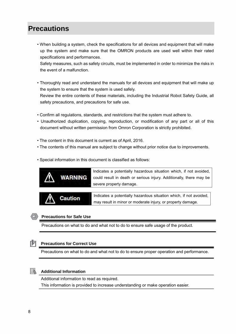
document without written permission from Omron Corporation is strictly prohibited. • The content in this document is current as of April, 2016. • The contents of this manual are subject to change without prior notice due to improvements. • Special information in this document is classified as follows:
Indicates a potentially hazardous situation which, if not avoided, could result in death or serious injury. Additionally, there may be severe property damage.
Indicates a potentially hazardous situation which, if not avoided, may result in minor or moderate injury, or property damage.
Precautions for Safe Use
Precautions on what to do and what not to do to ensure safe usage of the product.
Precautions for Correct Use
Precautions on what to do and what not to do to ensure proper operation and performance.
Additional Information Additional information to read as required. This information is provided to increase understanding or make operation easier.

9
Symbols
The triangle symbol indicates cautions (including warnings). The specific operation is shown in the triangle and explained in text. This example indicates a caution for electric shock.
The filled circle symbol indicates operations that you must do. The specific operation is shown in the circle and explained in text. This example indicates a general precaution.
10
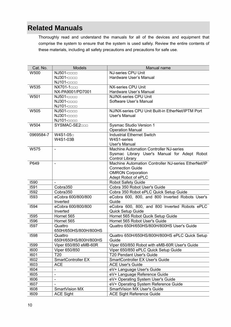
Related Manuals Thoroughly read and understand the manuals for all of the devices and equipment that comprise the system to ensure that the system is used safely. Review the entire contents of these materials, including all safety precautions and precautions for safe use.
Cat. No. Models Manual name W500 NJ501-□□□□
NJ301-□□□□ NJ101-□□□□
NJ-series CPU Unit Hardware User’s Manual
W535 NX701-1□□□ NX-PA9001/PD7001
NX-series CPU Unit Hardware User’s Manual
W501 NJ501-□□□□ NJ301-□□□□ NJ101-□□□□
NJ/NX-series CPU Unit Software User’s Manual
W505 NJ501-□□□□ NJ301-□□□□ NJ101-□□□□
NJ/NX-series CPU Unit Built-in EtherNet/IPTM Port User's Manual
W504 SYSMAC-SE2□□□ Sysmac Studio Version 1 Operation Manual
0969584-7 W4S1-05□ W4S1-03B
Industrial Ethernet Switch W4S1-series User's Manual
W575 - Machine Automation Controller NJ-series Sysmac Library User's Manual for Adept Robot Control Library
P649 - Machine Automation Controller NJ-series EtherNet/IP Connection Guide OMRON Corporation Adept Robot of ePLC
I590 - Robot Safety Guide I591 Cobra350 Cobra 350 Robot User's Guide I592 Cobra350 Cobra 350 Robot ePLC Quick Setup Guide I593 eCobra 600/800/800
Inverted eCobra 600, 800, and 800 Inverted Robots User's Guide
I594 eCobra 600/800/800 Inverted
eCobra 600, 800, and 800 Inverted Robots ePLC Quick Setup Guide
I595 Hornet 565 Hornet 565 Robot Qucik Setup Guide I596 Hornet 565 Hornet 565 Robot User's Guide I597 Quattro
650H/650HS/800H/800HS Quattro 650H/650HS/800H/800HS User's Guide
I598 Quattro 650H/650HS/800H/800HS
Quattro 650H/650HS/800H/800HS ePLC Quick Setup Guide
I599 Viper 650/850 eMB-60R Viper 650/850 Robot with eMB-60R User's Guide I600 Viper 650/850 Viper 650/850 ePLC Quick Setup Guide I601 T20 T20 Pendant User's Guide I602 SmartController EX SmartController EX User's Guide I603 ACE ACE User's Guide I604 - eV+ Language User's Guide I605 - eV+ Language Reference Guide I606 - eV+ Operating System User's Guide I607 - eV+ Operating System Reference Guide I608 SmartVision MX SmartVision MX User's Guide I609 ACE Sight ACE Sight Reference Guide
11
Revision History
A manual revision code appears as a suffix to the catalog number on the front and back covers of the manual.
Revision code
Date Revised content
01 April 2016 Original production
Cat. No. P103-E1-01
Revision code
12
CONTENTS
Introduction ................................................................. 2 Intended Audience ............................................................ 2 Applicable Products........................................................... 3
Terms and Conditions Agreement ............................................. 4 Robot System Products and Machine Automation Controller NJ/NX-series CPU Units . 4
Warranty, Limitations of Liability .............................................. 4 Application Considerations ................................................... 5 Disclaimers ................................................................ 5
Robot System Products ....................................................... 6 Automation Software Sysmac Studio ............................................ 7
WARRANTY ............................................................... 7 LIMITATION OF LIABILITY .................................................. 7 APPLICABLE CONDITIONS ................................................. 7 CHANGE IN SPECIFICATION ............................................... 7 ERRORS AND OMISSIONS ................................................. 7
Precautions ................................................................. 8 Related Manuals ............................................................ 10 Revision History ............................................................ 11 1. System Configuration ................................................... 14
1.1. System Configuration and Configuration Devices ........................... 14 1.2. Robot System .......................................................... 16 1.3. Function block list ....................................................... 17
2. Before You Begin ....................................................... 18 2.1. Downloading the Sysmac Library ......................................... 18 2.2. Installing the Sysmac Library ............................................. 23 2.3. Importing the Sysmac Library into Sysmac Studio ........................... 26
3. EtherNet/IP Settings ..................................................... 29 3.1. Communication Settings ................................................. 29
Communication Settings of Personal Computer ................................ 29 EtherNet/IP Communication Settings ......................................... 29
3.2. Global Variables ......................................................... 30 3.3. Tag Sets ............................................................... 31 3.4. Tag Data Link Tables .................................................... 31
4. EtherNet/IP Connections ................................................. 33 4.1. Procedural Sequence ................................................... 33 4.2. Robot Controller Settings ................................................ 35
Cable Connections ........................................................ 35 IP Address Settings ........................................................ 35
4.3. Controller Setup ........................................................ 36 IP Address Settings ........................................................ 36 Target Device Registration .................................................. 36 Registering Global Variables ................................................ 36 Tag Registration ........................................................... 36 Setting Connections ....................................................... 36 Transferring Project Data ................................................... 37
13
4.4. Confirming EtherNet/IP Communication .................................... 38 Connection Status Confirmation ............................................. 38 Data Exchange Confirmation ................................................ 38
5. Programming ........................................................... 39 5.1 Programming Overview .................................................. 39
Program name ............................................................ 40 Global variables ........................................................... 40 Internal and External Variables .............................................. 41 Sample Programs ......................................................... 43
5.2. Creating Sample Programs .............................................. 47 Adding Programs .......................................................... 47 Creating Global Variables ................................................... 50 Registering Internal and External Variables ................................... 52 Writing Programs .......................................................... 55 Setting Tasks to Global Variables ............................................ 57 Set Tasks to Programs ..................................................... 59
5.3. Debugging Programs .................................................... 61 Transferring Programs ..................................................... 61 Debugging Programs ...................................................... 61
6. Appendix - Initialization Method .......................................... 69 6.1. Initializing Controllers ................................................... 69
14
1. System Configuration
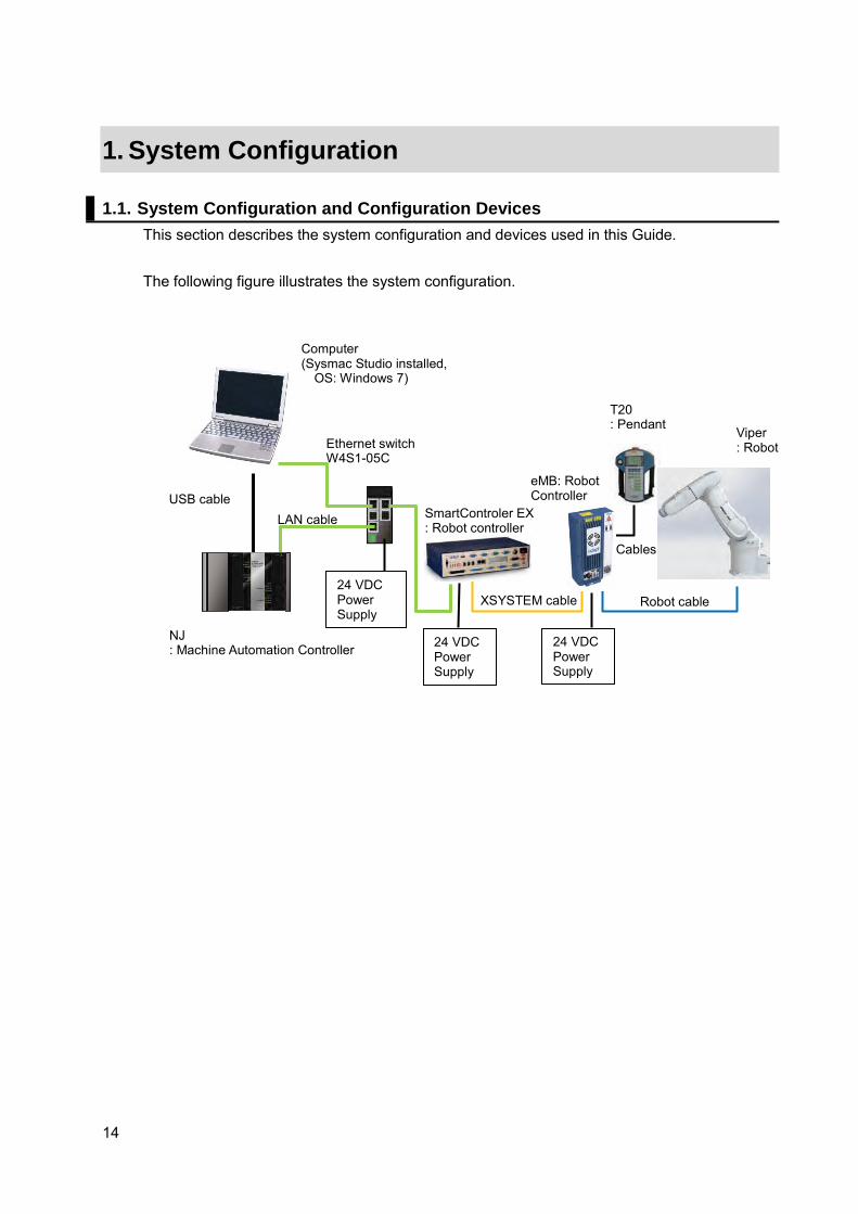
1.1. System Configuration and Configuration Devices This section describes the system configuration and devices used in this Guide. The following figure illustrates the system configuration.
Viper : Robot
NJ : Machine Automation Controller
Ethernet switch W4S1-05C
Computer (Sysmac Studio installed,
OS: Windows 7)
USB cable
24 VDC Power Supply
LAN cable
24 VDC Power Supply
XSYSTEM cable
SmartControler EX : Robot controller
Robot cable
Cables
T20 : Pendant
24 VDC Power Supply
eMB: Robot Controller
15
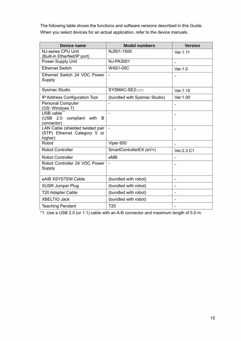
The following table shows the functions and software versions described in this Guide. When you select devices for an actual application, refer to the device manuals.
Device name Model numbers Version NJ-series CPU Unit (Built-in EtherNet/IP port)
NJ501-1500 Ver.1.11
Power Supply Unit NJ-PA3001 - Ethernet Switch W4S1-05C Ver.1.0 Ethernet Switch 24 VDC Power Supply
- -
Sysmac Studio SYSMAC-SE2□□□ Ver.1.15 IP Address Configuration Tool (bundled with Sysmac Studio) Ver.1.00 Personal Computer (OS: Windows 7)
- -
USB cable*1 (USB 2.0 compliant with B connector)
- -
LAN Cable (shielded twisted pair (STP) Ethernet Category 5 or higher)
- -
Robot Viper 650 - Robot Controller SmartControllerEX (eV+) Ver.2.3.C1 Robot Controller eMB - Robot Controller 24 VDC Power Supply
- -
eAIB XSYSTEM Cable (bundled with robot) - XUSR Jumper Plug (bundled with robot) - T20 Adapter Cable (bundled with robot) - XBELTIO Jack (bundled with robot) - Teaching Pendant T20 -
*1. Use a USB 2.0 (or 1.1) cable with an A-B connector and maximum length of 5.0 m.

16
1.2. Robot System In this Guide, a system will be configured to operate point-to-point connections using the Viper 650 vertically articulated robot. This Guide describes the procedures to set NJ Controller variable settings, EtherNet/IP connections, create programs using function blocks, and commission function blocks through program debugging and confirmation of robot operation. As illustrated in the following figure, the system configured in this Guide operates using point-to-point connections. (1) Confirming operation
Operation starts at the current position transitioning to target position 1 and then transitioning to target position 2.
(2) Robot motion positions
Position X Y Z RX RY RZ Current position 450 0 250 -180 180 -180 Target position: 1 450 100 150 -180 180 -180 Target position: 2 450 -100 150 -180 180 -180
(3) Motion control parameters (settings related to motion velocity)
Parameter Setting Target velocity 20 Target acceleration 100 Target deceleration 100 Maximum Velocity 100
(4) Move configuration (settings related to motion)
Parameter Setting Motion at approach height Offset position Approach height 50
Target position: 1 Target position: 2
Approach height Approach height
Current position Approach position 1
Departing position 1
Approach position 2
Departing position 2
17
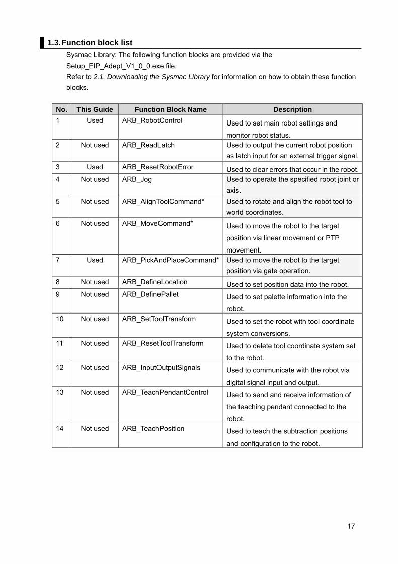
1.3. Function block list Sysmac Library: The following function blocks are provided via the Setup_EIP_Adept_V1_0_0.exe file. Refer to 2.1. Downloading the Sysmac Library for information on how to obtain these function blocks.
No. This Guide Function Block Name Description 1 Used ARB_RobotControl Used to set main robot settings and
monitor robot status. 2 Not used ARB_ReadLatch Used to output the current robot position
as latch input for an external trigger signal. 3 Used ARB_ResetRobotError Used to clear errors that occur in the robot. 4 Not used ARB_Jog Used to operate the specified robot joint or
axis. 5 Not used ARB_AlignToolCommand* Used to rotate and align the robot tool to
world coordinates. 6 Not used ARB_MoveCommand* Used to move the robot to the target
position via linear movement or PTP
movement. 7 Used ARB_PickAndPlaceCommand* Used to move the robot to the target
position via gate operation. 8 Not used ARB_DefineLocation Used to set position data into the robot. 9 Not used ARB_DefinePallet Used to set palette information into the
robot. 10 Not used ARB_SetToolTransform Used to set the robot with tool coordinate
system conversions. 11 Not used ARB_ResetToolTransform Used to delete tool coordinate system set
to the robot. 12 Not used ARB_InputOutputSignals Used to communicate with the robot via
digital signal input and output. 13 Not used ARB_TeachPendantControl Used to send and receive information of
the teaching pendant connected to the
robot. 14 Not used ARB_TeachPosition Used to teach the subtraction positions
and configuration to the robot.
18
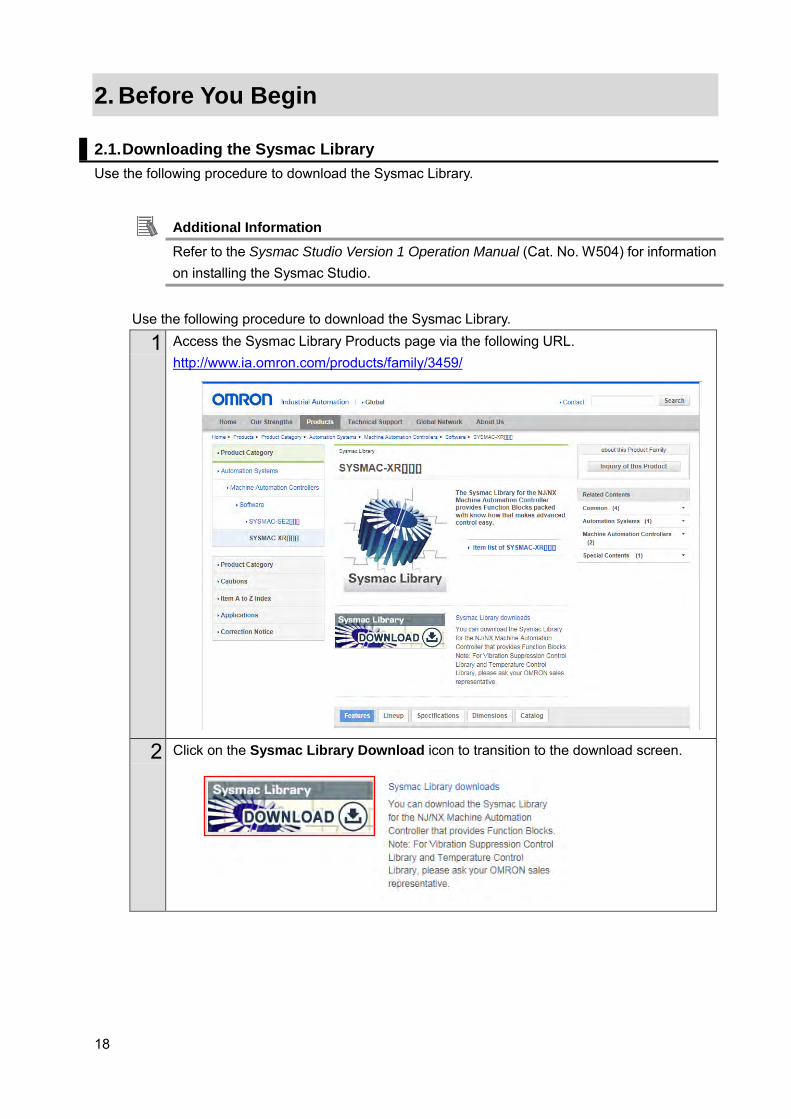
2. Before You Begin 2.1. Downloading the Sysmac Library Use the following procedure to download the Sysmac Library.
Additional Information Refer to the Sysmac Studio Version 1 Operation Manual (Cat. No. W504) for information on installing the Sysmac Studio.
Use the following procedure to download the Sysmac Library.
1 Access the Sysmac Library Products page via the following URL. http://www.ia.omron.com/products/family/3459/
2 Click on the Sysmac Library Download icon to transition to the download screen.

19
3 The download screen appears.
4 Accept the Software License Agreement and transition to the login screen by clicking the Agree the terms and move to Login Screen button.
5 Enter your Country/Region, E-mail address and License number of Sysmac Studio and then click Next to transition to the Sysmac Library Download Service.

20
6 From the Sysmac Library Download Service, right-click the Setup_EIP_Adept_V1_0_0.exe (11.6 MB) file under the Robot Control Library (SYSMAC-XR009) and select Save target as ....
21
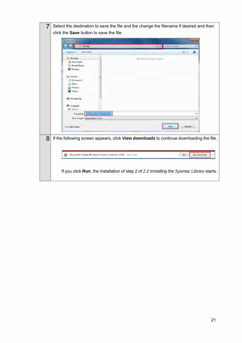
7 Select the destination to save the file and the change the filename if desired and then click the Save button to save the file.
8 If the following screen appears, click View downloads to continue downloading the file.
If you click Run, the installation of step 2 of 2.2 Installing the Sysmac Library starts.
22
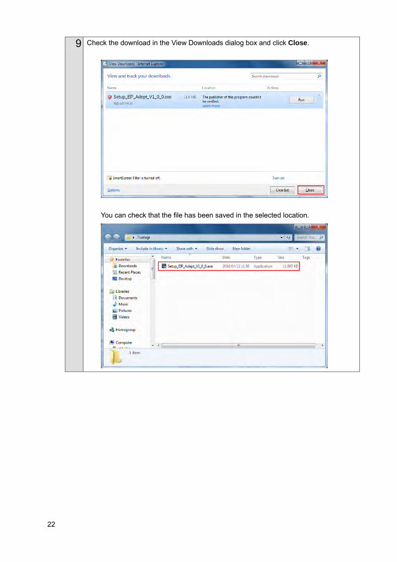
9 Check the download in the View Downloads dialog box and click Close.
You can check that the file has been saved in the selected location.
23
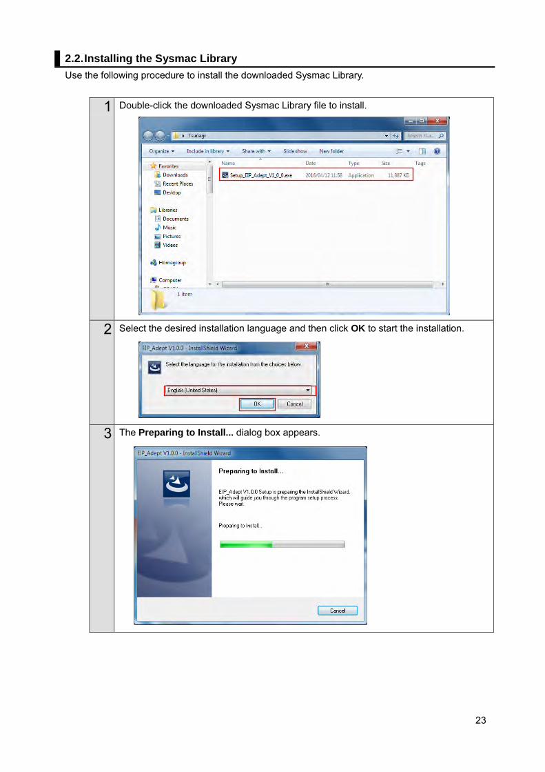
2.2. Installing the Sysmac Library Use the following procedure to install the downloaded Sysmac Library.
1 Double-click the downloaded Sysmac Library file to install.
2 Select the desired installation language and then click OK to start the installation.
3 The Preparing to Install... dialog box appears.
24
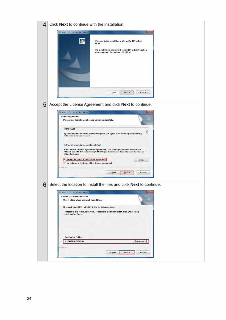
4 Click Next to continue with the installation.
5 Accept the License Agreement and click Next to continue.
6 Select the location to install the files and click Next to continue.
25
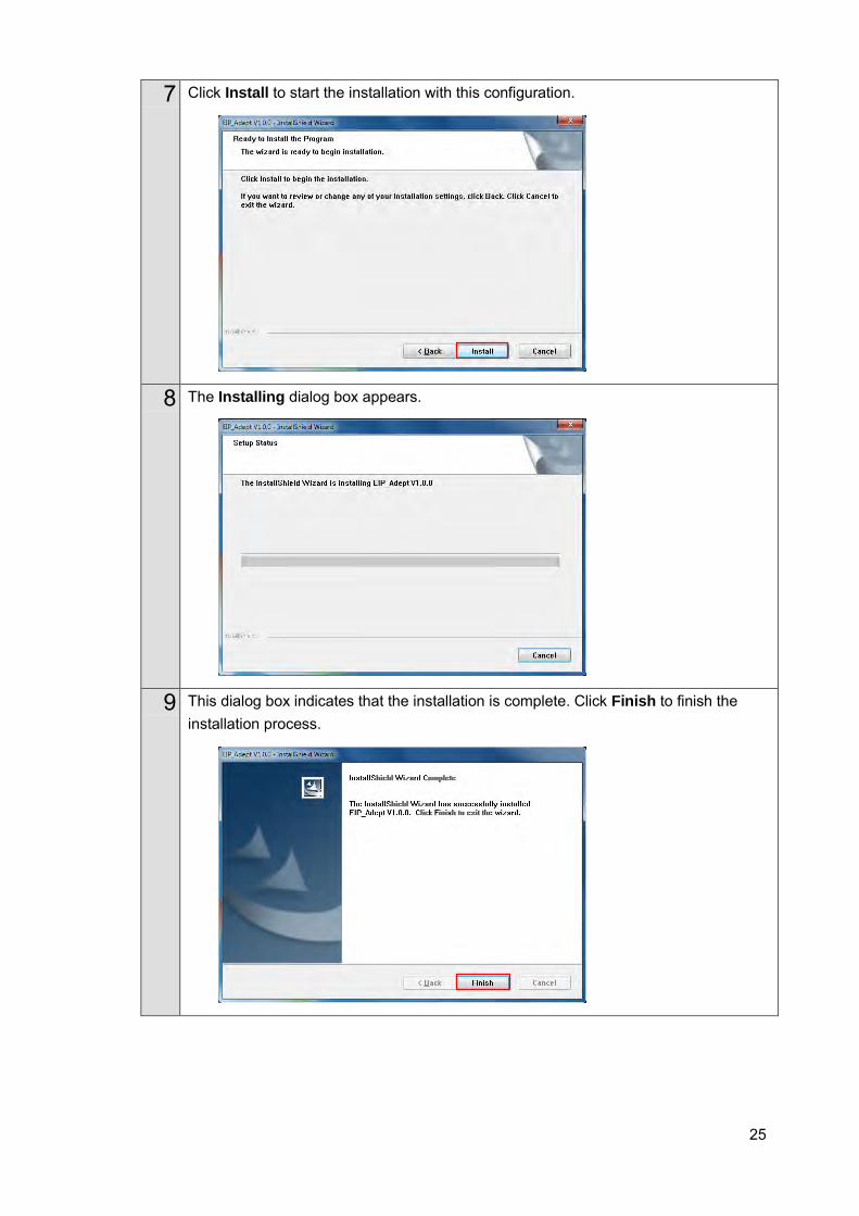
7 Click Install to start the installation with this configuration.
8 The Installing dialog box appears.
9 This dialog box indicates that the installation is complete. Click Finish to finish the installation process.
26
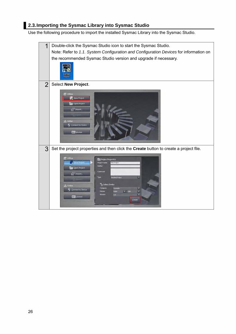
2.3. Importing the Sysmac Library into Sysmac Studio Use the following procedure to import the installed Sysmac Library into the Sysmac Studio.
1 Double-click the Sysmac Studio icon to start the Sysmac Studio. Note: Refer to 1.1. System Configuration and Configuration Devices for information on the recommended Sysmac Studio version and upgrade if necessary.
2 Select New Project.
3 Set the project properties and then click the Create button to create a project file.

27
4 Start the project file.
5 From the menu, select Project, Library, and then Show References.
6 Select the Include the referenced libraries when using the project check box, click the + button, and select the reference library.
28
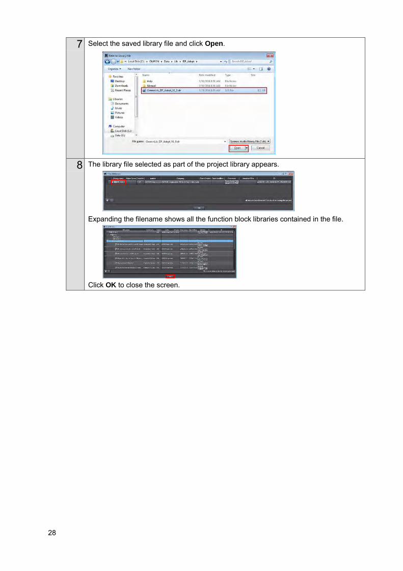
7 Select the saved library file and click Open.
8 The library file selected as part of the project library appears.
Expanding the filename shows all the function block libraries contained in the file.
Click OK to close the screen.
29
3. EtherNet/IP Settings This section describes the setting contents of communication settings, global variables, tag sets, and tag data link that are all defined in this document.
3.1. Communication Settings
The parameters that are set in this document are shown below.
Communication Settings of Personal Computer The parameters for Robot Controller are set on a personal computer for setting via an Ethernet network. The following table shows the parameters required for connecting a personal computer for setting and Robot Controller using the Ethernet communications.
Setting Personal computer for setting Robot controller IP address 172.16.169.10 *2 172.16.169.118 (default value) *1 Subnet mask 255.255.0.0 255.255.0.0 (default value) *1. Each Robot Controller is allocated with a unique IP address.
Set an IP address of a personal computer for setting according to an IP address of Robot Controller. This IP address provided above is for Robot Controller used in this document..
*2. Set an IP address of personal computer for setting, which needs to have a different host part of an IP address from the one of Robot Controller.
EtherNet/IP Communication Settings
The parameters required for connecting Controller to Robot Controller via EtherNet/IP are shown below.
Setting Controller Robot controller IP address 192.168.250.1 192.168.250.2 Subnet mask 255.255.255.0 255.255.255.0
30
3.2. Global Variables The following table shows details on global variables. The Controller handles tag data link data as global variables.
Name Data type Network publish
Robot controller allocation
Data size (bytes)
to_Robot BYTE[214] Output Input area 214 from_Robot BYTE[284] Input Output area 284 gRobotData OmronLib\EIP_Adept\sAR
B_ROBOT_DATA_REF Do not publish
- -
Precautions for Correct Use
When the data size of the Robot controller tag data link has an odd number of bytes, the data types of global variables must be declared as BYTE and not BOOL.
Additional Information The Sysmac Studio supports two types of input formats as follows to specify a variable data type as an array.
(1) BOOL [16] (2) ARRAY[0..15] OF BOOL
Even if you input the data type in format (1), the Sysmac Studio automatically converts the format to format (2) so that the variable table always shows the data type in format (2). In this Guide, this is referred to as "BOOL [16]" for simplicity. The above example represents BOOL data type that consists a 16-element array.
31
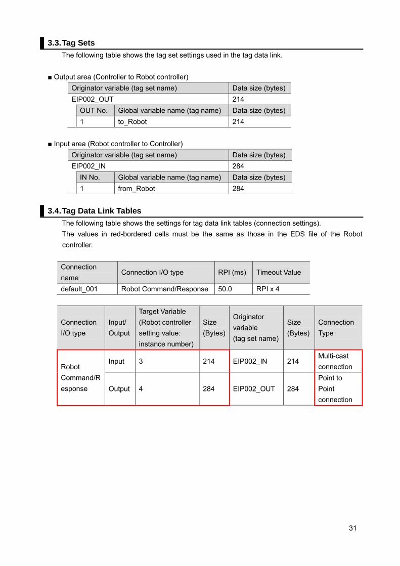
3.3. Tag Sets The following table shows the tag set settings used in the tag data link.
■ Output area (Controller to Robot controller)
Originator variable (tag set name) Data size (bytes) EIP002_OUT 214 OUT No. Global variable name (tag name) Data size (bytes) 1 to_Robot 214
■ Input area (Robot controller to Controller)
Originator variable (tag set name) Data size (bytes) EIP002_IN 284 IN No. Global variable name (tag name) Data size (bytes) 1 from_Robot 284
3.4. Tag Data Link Tables
The following table shows the settings for tag data link tables (connection settings). The values in red-bordered cells must be the same as those in the EDS file of the Robot controller.
Connection name
Connection I/O type RPI (ms) Timeout Value
default_001 Robot Command/Response 50.0 RPI x 4
Connection I/O type
Input/Output
Target Variable (Robot controller setting value: instance number)
Size (Bytes)
Originator variable (tag set name)
Size (Bytes)
Connection Type
Robot Command/Response
Input 3 214 EIP002_IN 214 Multi-cast connection
Output 4 284 EIP002_OUT 284 Point to Point connection

32
■Description of Robot controller input area Controller Robot controller Global variables
Array number
Area Name Size Port number
to_Robot [0] Robot_Command Input area (214 bytes)
Insturuction_Command 2 - [2] Jog_Mode_Command 2 - [4] Output_Signals_Command 2 #1641 to
#1642 [6] Motoin_QualiFier_Command 2 - [8] Motion_Parameter 20 - [28] Locatoin1 24 - [52] Pallet_Description 14 - [66] MCP_Communication 90 - [156] Location2 24 - [180] Vision_Commands 8 - [188] Belt_Commands 8 - [196] Belt_Latch_Commands 4 - [200] Belt_Description 14 -
■Description of Robot controller output area Controller Robot controller Global variables
Array number
Area Name Size Port number
from_Robot
[0] Robot_Status Output area (284 bytes)
System_State 18 #0641 to #0642
[18] MCP_Status 6 - [24] Error_Status 92 - [116] Locations 72 - [188] Vision_Status 40 - [228] Belt_Status 40 - [268] Belt_Latch_Status 16 -
33
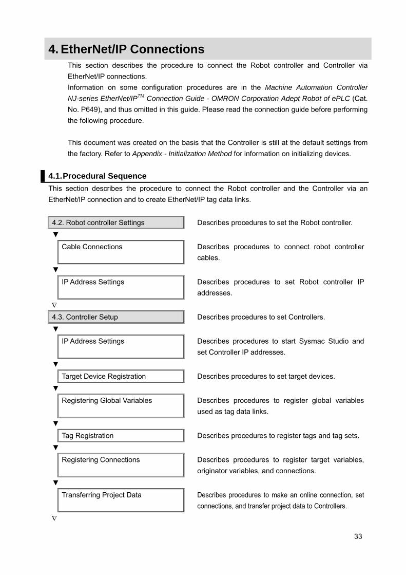
4. EtherNet/IP Connections This section describes the procedure to connect the Robot controller and Controller via EtherNet/IP connections. Information on some configuration procedures are in the Machine Automation Controller NJ-series EtherNet/IPTM Connection Guide - OMRON Corporation Adept Robot of ePLC (Cat. No. P649), and thus omitted in this guide. Please read the connection guide before performing the following procedure. This document was created on the basis that the Controller is still at the default settings from the factory. Refer to Appendix - Initialization Method for information on initializing devices.
4.1. Procedural Sequence This section describes the procedure to connect the Robot controller and the Controller via an EtherNet/IP connection and to create EtherNet/IP tag data links.
4.2. Robot controller Settings Describes procedures to set the Robot controller.
▼
Cable Connections
Describes procedures to connect robot controller cables.
▼
IP Address Settings
Describes procedures to set Robot controller IP addresses.
∇
4.3. Controller Setup Describes procedures to set Controllers.
▼
IP Address Settings
Describes procedures to start Sysmac Studio and set Controller IP addresses.
▼
Target Device Registration Describes procedures to set target devices.
▼
Registering Global Variables
Describes procedures to register global variables used as tag data links.
▼
Tag Registration Describes procedures to register tags and tag sets.
▼
Registering Connections
Describes procedures to register target variables, originator variables, and connections.
▼
Transferring Project Data
Describes procedures to make an online connection, set connections, and transfer project data to Controllers.
∇

34
4.4. Confirming EtherNet/IP Communication
Describes procedures to confirm that EtherNet/IP tag data links are functioning properly.
▼
Connection Status Confirmation
Describes procedures to confirm the status of EtherNet/IP connections.
▼
Data Exchange Confirmation
Describes procedures to confirm that data is exchanged correctly.
35
4.2. Robot Controller Settings This section describes procedures to set the Robot controller.
Cable Connections This section describes procedures to connect robot controller cables. For more information, refer to 7.2.1 Cable Connection in the Machine Automation Controller NJ-series EtherNet/IPTM Connection Guide - OMRON Corporation Adept Robot of ePLC (Cat. No. P649).
IP Address Settings This section describes procedures to set Robot controller IP addresses.
Precautions for Correct Use
Use a personal computer and the Ethernet connection to confirm the settings of the Robot controller. Note that the personal computer settings may need to be reconfigured.
For more information, refer to 7.2.2 IP Addresses in the Machine Automation Controller NJ-series EtherNet/IPTM Connection Guide - OMRON Corporation Adept Robot of ePLC (Cat. No. P649).
36
4.3. Controller Setup This section describes procedures to set Controllers.
IP Address Settings This section describes procedures to start Sysmac Studio and set Controller IP addresses. Sysmac Studio and a USB driver must be installed beforehand. For more information, refer to 7.3.1 IP Address Settings in the Machine Automation Controller NJ-series EtherNet/IPTM Connection Guide - OMRON Corporation Adept Robot of ePLC (Cat. No. P649).
Target Device Registration
This section describes procedures to register target devices for tag data links. For more information, refer to 7.3.2 Target Device Registration in the Machine Automation Controller NJ-series EtherNet/IPTM Connection Guide - OMRON Corporation Adept Robot of ePLC (Cat. No. P649).
Registering Global Variables This section describes procedures to register global variables used as tag data links. For more information, refer to 7.3.3 Global Variables in the Machine Automation Controller NJ-series EtherNet/IPTM Connection Guide - OMRON Corporation Adept Robot of ePLC (Cat. No. P649).
Tag Registration
This section describes procedures to register tags and tag sets used in tag data links.
For more information, refer to 7.3.4 Tag Registration in the Machine Automation Controller NJ-series EtherNet/IPTM Connection Guide - OMRON Corporation Adept Robot of ePLC (Cat. No. P649).
Setting Connections
This section describes procedures to register target variables (connection establishment), originator variables (connection establishment), and connections (tag data link tables). For more information, refer to 7.3.5 Connection Settings in the Machine Automation Controller NJ-series EtherNet/IPTM Connection Guide - OMRON Corporation Adept Robot of ePLC (Cat. No. P649).
37
Transferring Project Data This section describes procedures to make an online connection and transfer project data to Controllers.
The devices or machines may operate unexpectedly regardless of the operating mode of the CPU Unit when transferring the following data from Sysmac Studio; user programs, configurations and setup data, device variables, and values in memory used for CJ-series Units. Confirm safety at the destination slave before transferring project data.
For more information, refer to 7.3.6 Transferring Project Data in the Machine Automation Controller NJ-series EtherNet/IPTM Connection Guide - OMRON Corporation Adept Robot of ePLC (Cat. No. P649).
38
4.4. Confirming EtherNet/IP Communication This section describes procedures to confirm that EtherNet/IP tag data links are functioning properly.
Connection Status Confirmation This section describes procedures to confirm the status of EtherNet/IP connections. For more information, refer to 7.4.1 Confirming Connection Status in the Machine Automation Controller NJ-series EtherNet/IPTM Connection Guide - OMRON Corporation Adept Robot of ePLC (Cat. No. P649).
Data Exchange Confirmation
This section describes procedures to confirm that data is exchanged correctly via tag data links. For more information, refer to 7.4.2 Data Exchange Confirmation in the Machine Automation Controller NJ-series EtherNet/IPTM Connection Guide - OMRON Corporation Adept Robot of ePLC (Cat. No. P649).
39
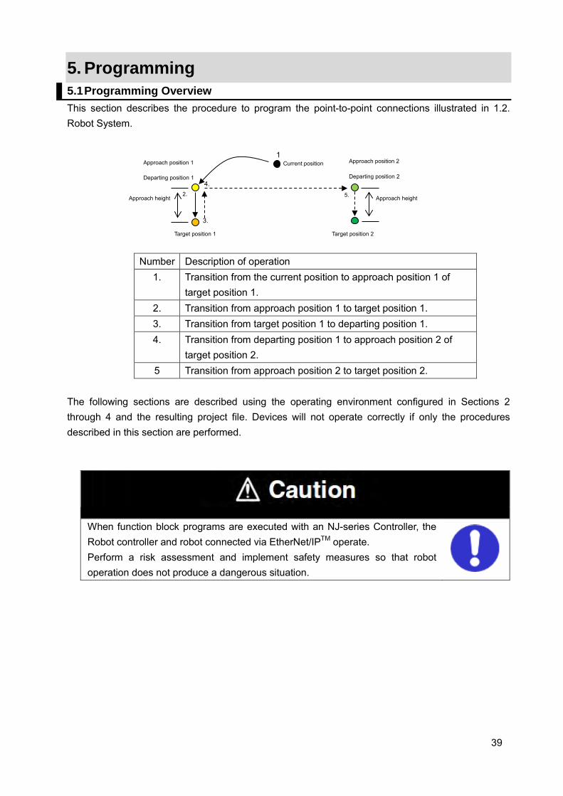
5. Programming 5.1 Programming Overview This section describes the procedure to program the point-to-point connections illustrated in 1.2. Robot System.
Number Description of operation 1. Transition from the current position to approach position 1 of
target position 1. 2. Transition from approach position 1 to target position 1. 3. Transition from target position 1 to departing position 1. 4. Transition from departing position 1 to approach position 2 of
target position 2. 5 Transition from approach position 2 to target position 2.
The following sections are described using the operating environment configured in Sections 2 through 4 and the resulting project file. Devices will not operate correctly if only the procedures described in this section are performed.
When function block programs are executed with an NJ-series Controller, the Robot controller and robot connected via EtherNet/IPTM operate. Perform a risk assessment and implement safety measures so that robot operation does not produce a dangerous situation.
1
2.
3.
4. 5.
Target position 1 Target position 2
Approach height Approach height
Current position Approach position 1
Departing position 1
Approach position 2
Departing position 2
40
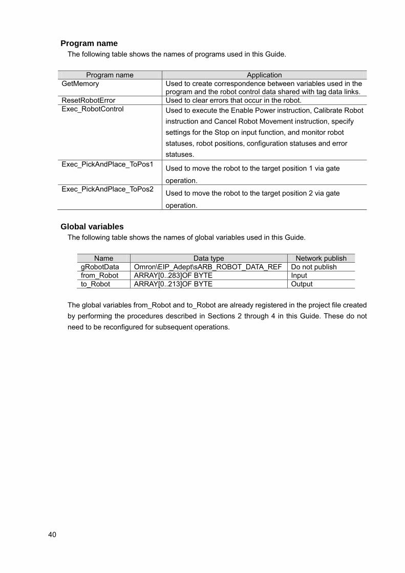
Program name The following table shows the names of programs used in this Guide.
Program name Application
GetMemory Used to create correspondence between variables used in the program and the robot control data shared with tag data links.
ResetRobotError Used to clear errors that occur in the robot. Exec_RobotControl Used to execute the Enable Power instruction, Calibrate Robot
instruction and Cancel Robot Movement instruction, specify settings for the Stop on input function, and monitor robot statuses, robot positions, configuration statuses and error statuses.
Exec_PickAndPlace_ToPos1 Used to move the robot to the target position 1 via gate
operation. Exec_PickAndPlace_ToPos2 Used to move the robot to the target position 2 via gate
operation. Global variables
The following table shows the names of global variables used in this Guide.
Name Data type Network publish gRobotData Omron\EIP_Adept\sARB_ROBOT_DATA_REF Do not publish from_Robot ARRAY[0..283]OF BYTE Input to_Robot ARRAY[0..213]OF BYTE Output
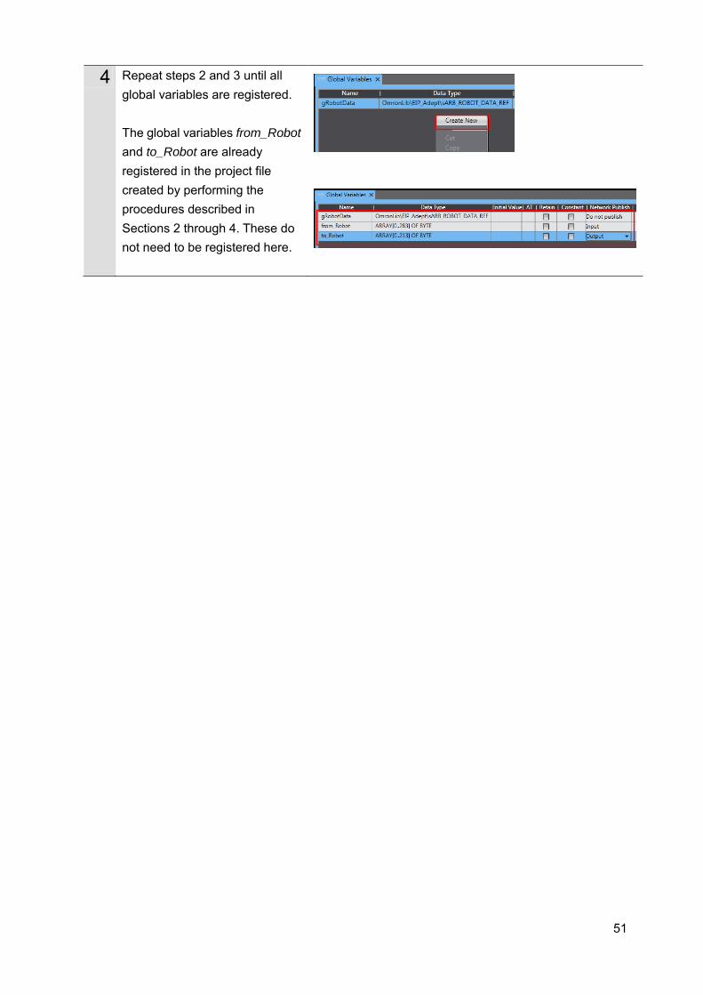
The global variables from_Robot and to_Robot are already registered in the project file created by performing the procedures described in Sections 2 through 4 in this Guide. These do not need to be reconfigured for subsequent operations.
41
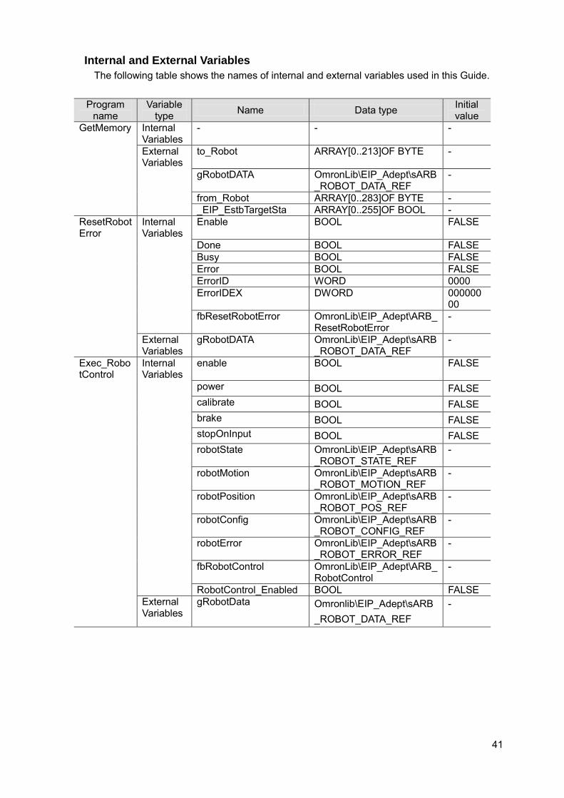
Internal and External Variables The following table shows the names of internal and external variables used in this Guide.
Program name
Variable type Name Data type Initial
value GetMemory Internal
Variables - - -
External Variables
to_Robot ARRAY[0..213]OF BYTE -
gRobotDATA OmronLib\EIP_Adept\sARB_ROBOT_DATA_REF
-
from_Robot ARRAY[0..283]OF BYTE - _EIP_EstbTargetSta ARRAY[0..255]OF BOOL -
ResetRobotError
Internal Variables
Enable BOOL FALSE
Done BOOL FALSE Busy BOOL FALSE Error BOOL FALSE ErrorID WORD 0000 ErrorIDEX DWORD 000000
00 fbResetRobotError OmronLib\EIP_Adept\ARB_
ResetRobotError -
External Variables
gRobotDATA OmronLib\EIP_Adept\sARB_ROBOT_DATA_REF
-
Exec_RobotControl
Internal Variables
enable BOOL FALSE
power BOOL FALSE calibrate BOOL FALSE brake BOOL FALSE stopOnInput BOOL FALSE robotState OmronLib\EIP_Adept\sARB
_ROBOT_STATE_REF -
robotMotion OmronLib\EIP_Adept\sARB_ROBOT_MOTION_REF
-
robotPosition OmronLib\EIP_Adept\sARB_ROBOT_POS_REF
-
robotConfig OmronLib\EIP_Adept\sARB_ROBOT_CONFIG_REF
-
robotError OmronLib\EIP_Adept\sARB_ROBOT_ERROR_REF
-
fbRobotControl OmronLib\EIP_Adept\ARB_RobotControl
-
RobotControl_Enabled BOOL FALSE External Variables
gRobotData Omronlib\EIP_Adept\sARB_ROBOT_DATA_REF
-
42
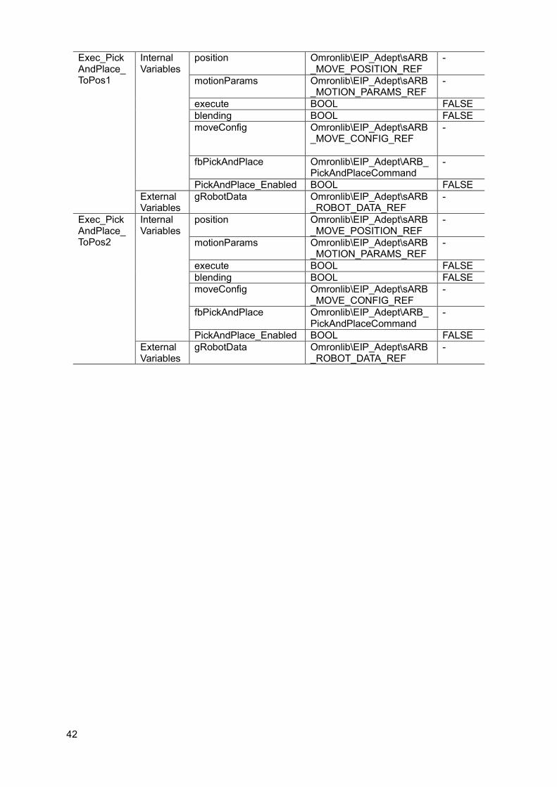
Exec_PickAndPlace_ToPos1
Internal Variables
position Omronlib\EIP_Adept\sARB_MOVE_POSITION_REF
-
motionParams Omronlib\EIP_Adept\sARB_MOTION_PARAMS_REF
-
execute BOOL FALSE blending BOOL FALSE moveConfig Omronlib\EIP_Adept\sARB
_MOVE_CONFIG_REF
-
fbPickAndPlace Omronlib\EIP_Adept\ARB_PickAndPlaceCommand
-
PickAndPlace_Enabled BOOL FALSE External Variables
gRobotData Omronlib\EIP_Adept\sARB_ROBOT_DATA_REF
-
Exec_PickAndPlace_ToPos2
Internal Variables
position Omronlib\EIP_Adept\sARB_MOVE_POSITION_REF
-
motionParams Omronlib\EIP_Adept\sARB_MOTION_PARAMS_REF
-
execute BOOL FALSE blending BOOL FALSE moveConfig Omronlib\EIP_Adept\sARB
_MOVE_CONFIG_REF -
fbPickAndPlace Omronlib\EIP_Adept\ARB_PickAndPlaceCommand
-
PickAndPlace_Enabled BOOL FALSE External Variables
gRobotData Omronlib\EIP_Adept\sARB_ROBOT_DATA_REF
-
43
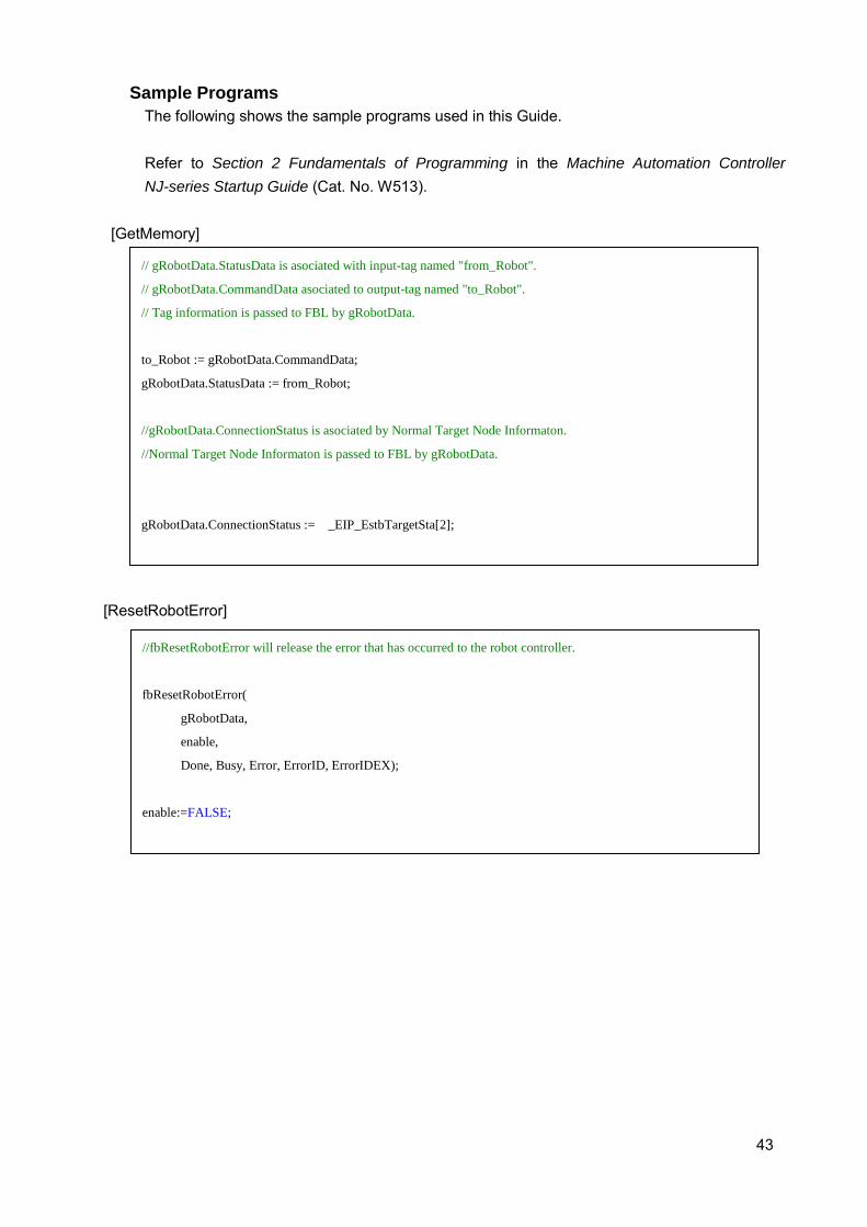
Sample Programs The following shows the sample programs used in this Guide.
Refer to Section 2 Fundamentals of Programming in the Machine Automation Controller NJ-series Startup Guide (Cat. No. W513).
[GetMemory] [ResetRobotError]
// gRobotData.StatusData is asociated with input-tag named "from_Robot".
// gRobotData.CommandData asociated to output-tag named "to_Robot".
// Tag information is passed to FBL by gRobotData.
to_Robot := gRobotData.CommandData;
gRobotData.StatusData := from_Robot;
//gRobotData.ConnectionStatus is asociated by Normal Target Node Informaton.
//Normal Target Node Informaton is passed to FBL by gRobotData.
gRobotData.ConnectionStatus := _EIP_EstbTargetSta[2];
//fbResetRobotError will release the error that has occurred to the robot controller.
fbResetRobotError(
gRobotData,
enable,
Done, Busy, Error, ErrorID, ErrorIDEX);
enable:=FALSE;
44
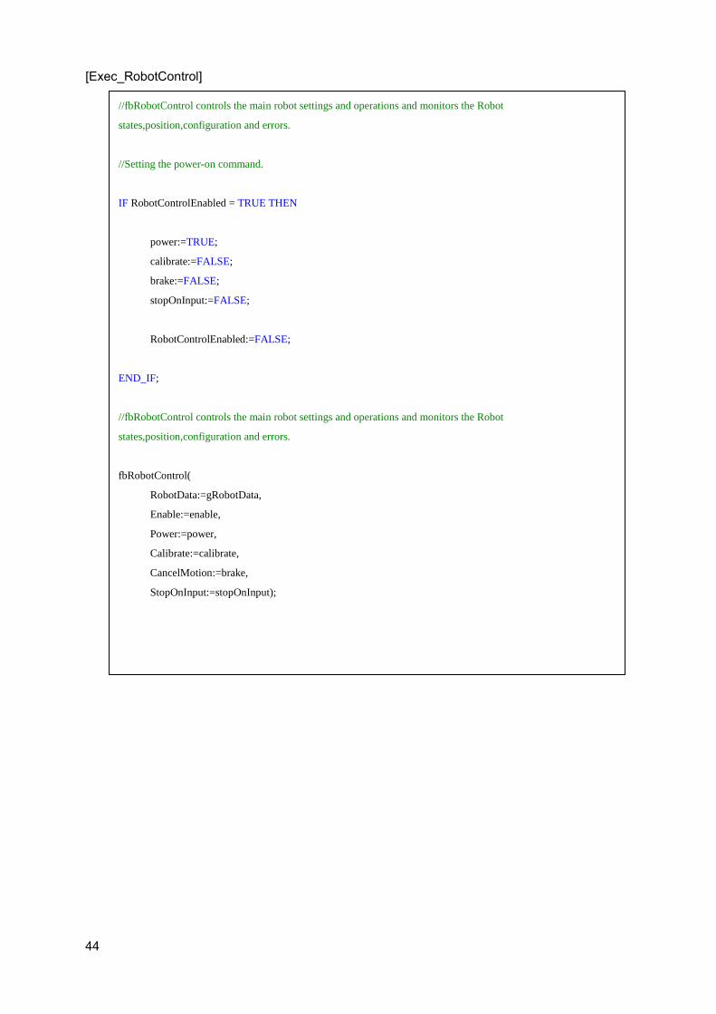
[Exec_RobotControl]
//fbRobotControl controls the main robot settings and operations and monitors the Robot
states,position,configuration and errors.
//Setting the power-on command.
IF RobotControlEnabled = TRUE THEN
power:=TRUE;
calibrate:=FALSE;
brake:=FALSE;
stopOnInput:=FALSE;
RobotControlEnabled:=FALSE;
END_IF;
//fbRobotControl controls the main robot settings and operations and monitors the Robot
states,position,configuration and errors.
fbRobotControl(
RobotData:=gRobotData,
Enable:=enable,
Power:=power,
Calibrate:=calibrate,
CancelMotion:=brake,
StopOnInput:=stopOnInput);

45
[Exec_PickAndPlace_ToPos1]
//Setting Target position, operating parameters, operating configuration.
//Depart and Approach heights are equal.
IF PickAndPlace_Enabled= TRUE THEN
position.Position[0] := 450;
position.Position[1] := -100;
position.Position[2] := 150;
position.Position[3] := -180;
position.Position[4] := 180;
position.Position[5] := -180;
motionParams.Speed := 20;
motionParams.Acceleration :=100;
motionParams.Deceleration := 100;
motionParams.SpeedLimit := 100;
moveConfig.AbsoluteApproach :=FALSE;
moveConfig.ApproachHeight :=50;
PickAndPlace_Enabled:= FALSE;
END_IF;
//fbPickAndPlace will achieve to the target position while Depart, Approach and Move motion.
fbPickAndPlace(
RobotData:=gRobotData,
Execute:=execute,
Position:=position,
Blending:=blending,
MotionParams:=motionParams,
MoveConfig:=moveConfig);
execute:=FALSE;
46
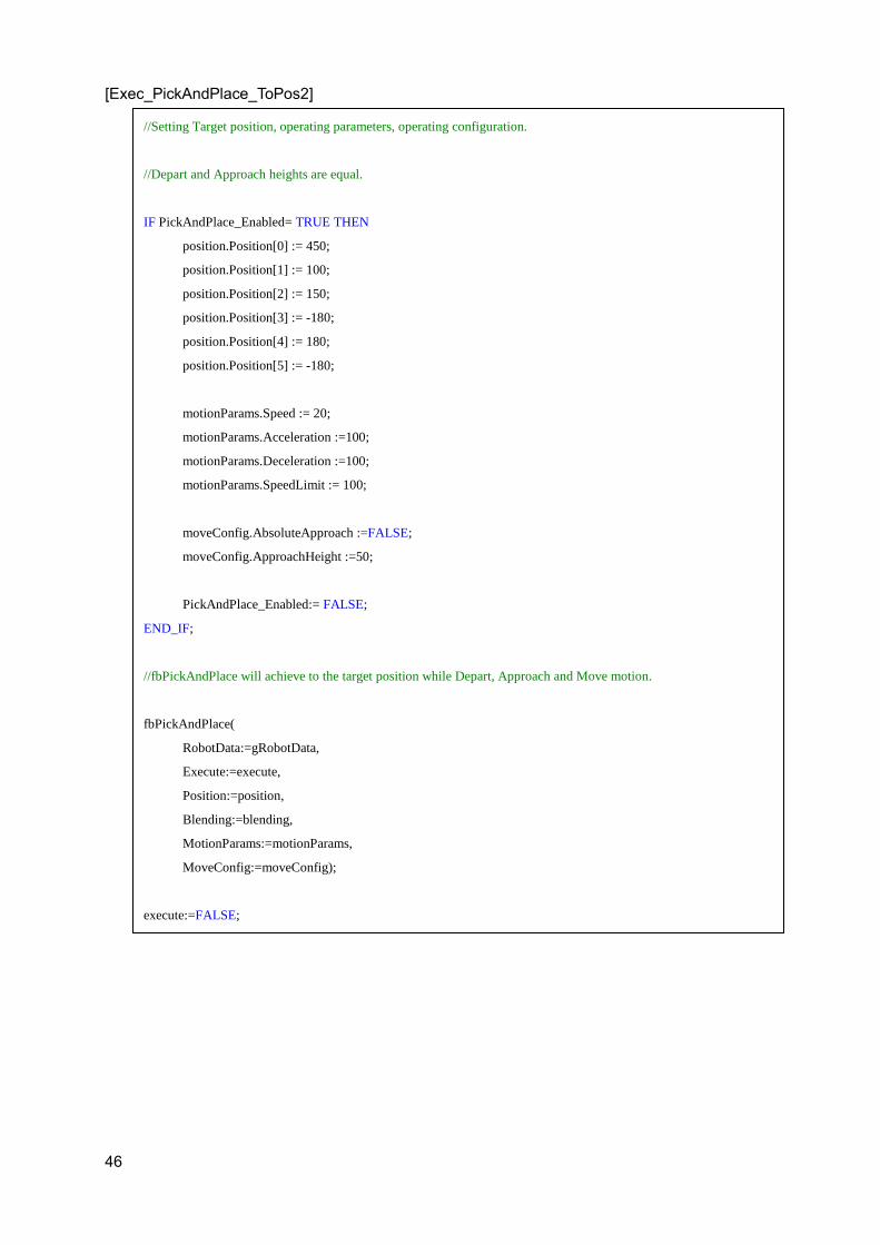
[Exec_PickAndPlace_ToPos2]
//Setting Target position, operating parameters, operating configuration.
//Depart and Approach heights are equal.
IF PickAndPlace_Enabled= TRUE THEN
position.Position[0] := 450;
position.Position[1] := 100;
position.Position[2] := 150;
position.Position[3] := -180;
position.Position[4] := 180;
position.Position[5] := -180;
motionParams.Speed := 20;
motionParams.Acceleration :=100;
motionParams.Deceleration :=100;
motionParams.SpeedLimit := 100;
moveConfig.AbsoluteApproach :=FALSE;
moveConfig.ApproachHeight :=50;
PickAndPlace_Enabled:= FALSE;
END_IF;
//fbPickAndPlace will achieve to the target position while Depart, Approach and Move motion.
fbPickAndPlace(
RobotData:=gRobotData,
Execute:=execute,
Position:=position,
Blending:=blending,
MotionParams:=motionParams,
MoveConfig:=moveConfig);
execute:=FALSE;

47
5.2. Creating Sample Programs Adding Programs
Use this procedure to add names to your programs. For the names of the programs, refer to Program name in 5.1 Programming Overview.
The following sections are described using the project file set in Sections 2 through 4 to create programs. If you are continuing from Section 4 in one session, you do not need to import the project file created using steps 1 through 4.
1 Double-click the Sysmac Studio icon to start the Sysmac Studio.
2 Select Import.
3 The Import file dialog appears. Select the exported project file created performing the procedures in Sections 2 through 4 and then click Open. * Here,
omron_ePLC_EIP_V100 is selected.
4 Start the project file.
48
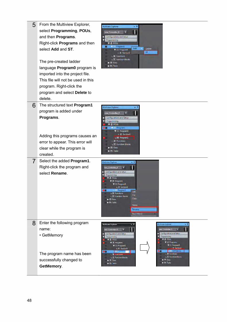
5 From the Multiview Explorer, select Programming, POUs, and then Programs. Right-click Programs and then select Add and ST. The pre-created ladder language Program0 program is imported into the project file. This file will not be used in this program. Right-click the program and select Delete to delete.
6 The structured text Program1 program is added under Programs. Adding this programs causes an error to appear. This error will clear while the program is created.
7 Select the added Program1. Right-click the program and select Rename.
8 Enter the following program name: • GetMemory The program name has been successfully changed to GetMemory.
49
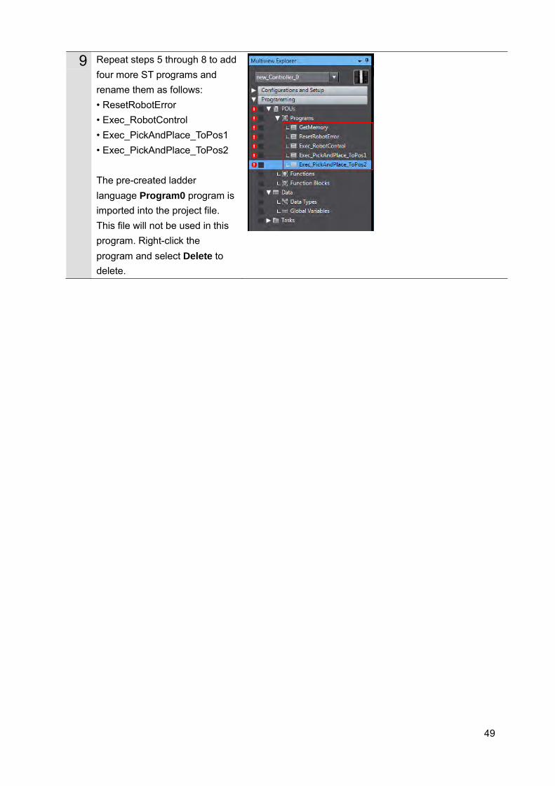
9 Repeat steps 5 through 8 to add four more ST programs and rename them as follows: • ResetRobotError • Exec_RobotControl • Exec_PickAndPlace_ToPos1 • Exec_PickAndPlace_ToPos2 The pre-created ladder language Program0 program is imported into the project file. This file will not be used in this program. Right-click the program and select Delete to delete.
50
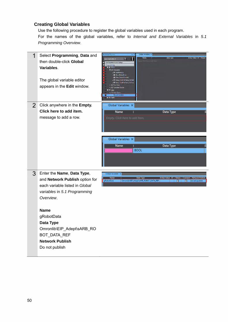
Creating Global Variables Use the following procedure to register the global variables used in each program. For the names of the global variables, refer to Internal and External Variables in 5.1 Programming Overview.
1 Select Programming, Data and then double-click Global Variables. The global variable editor appears in the Edit window.
2 Click anywhere in the Empty.
Click here to add item. message to add a row.
3 Enter the Name, Data Type, and Network Publish option for each variable listed in Global variables in 5.1 Programming Overview. Name gRobotData Data Type Omronlib\EIP_Adept\sARB_ROBOT_DATA_REF Network Publish Do not publish
51
4 Repeat steps 2 and 3 until all global variables are registered. The global variables from_Robot and to_Robot are already registered in the project file created by performing the procedures described in Sections 2 through 4. These do not need to be registered here.
52
Registering Internal and External Variables Use the following procedure to register the internal and external variables used in each program. For the names of the global variables, refer to Internal and External Variables in 5.1 Programming Overview.
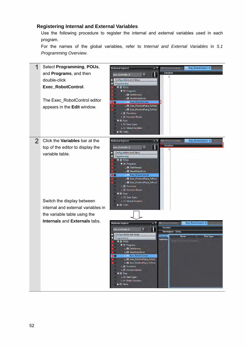
1 Select Programming, POUs, and Programs, and then double-click Exec_RobotControl. The Exec_RobotControl editor appears in the Edit window.
2 Click the Variables bar at the top of the editor to display the variable table. Switch the display between internal and external variables in the variable table using the Internals and Externals tabs.
53
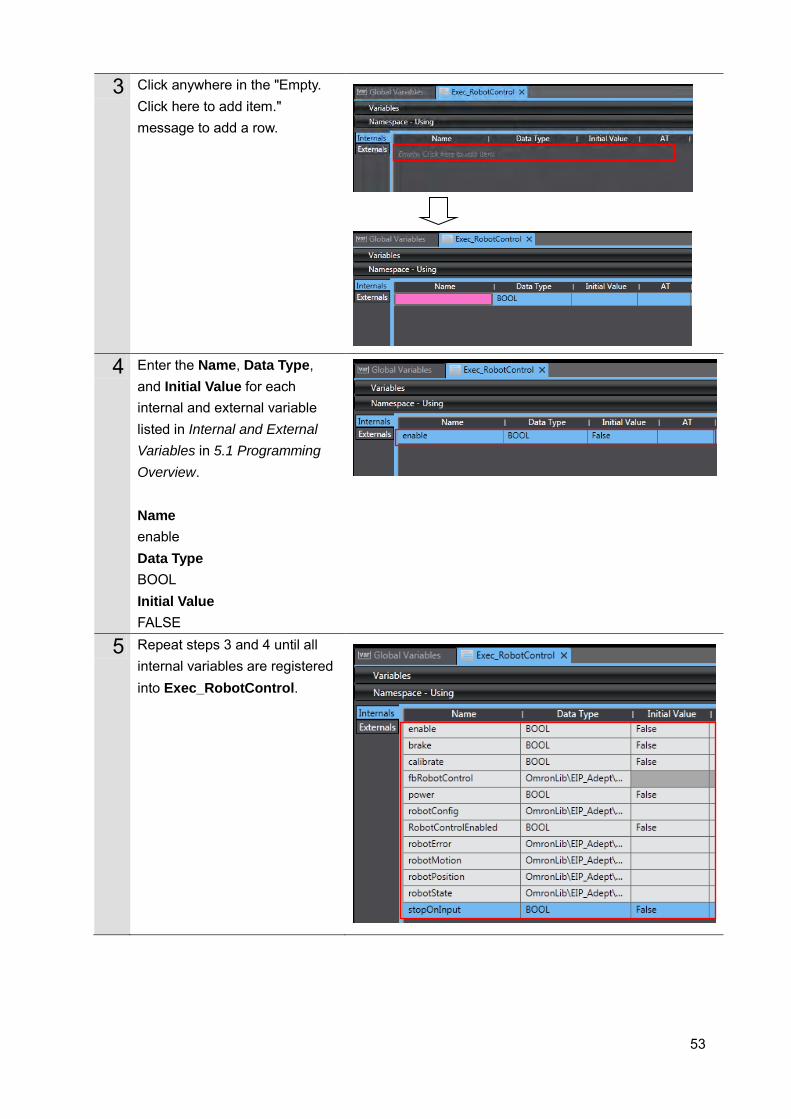
3 Click anywhere in the "Empty. Click here to add item." message to add a row.
4 Enter the Name, Data Type, and Initial Value for each internal and external variable listed in Internal and External Variables in 5.1 Programming Overview. Name enable Data Type BOOL Initial Value FALSE
5 Repeat steps 3 and 4 until all internal variables are registered into Exec_RobotControl.
54
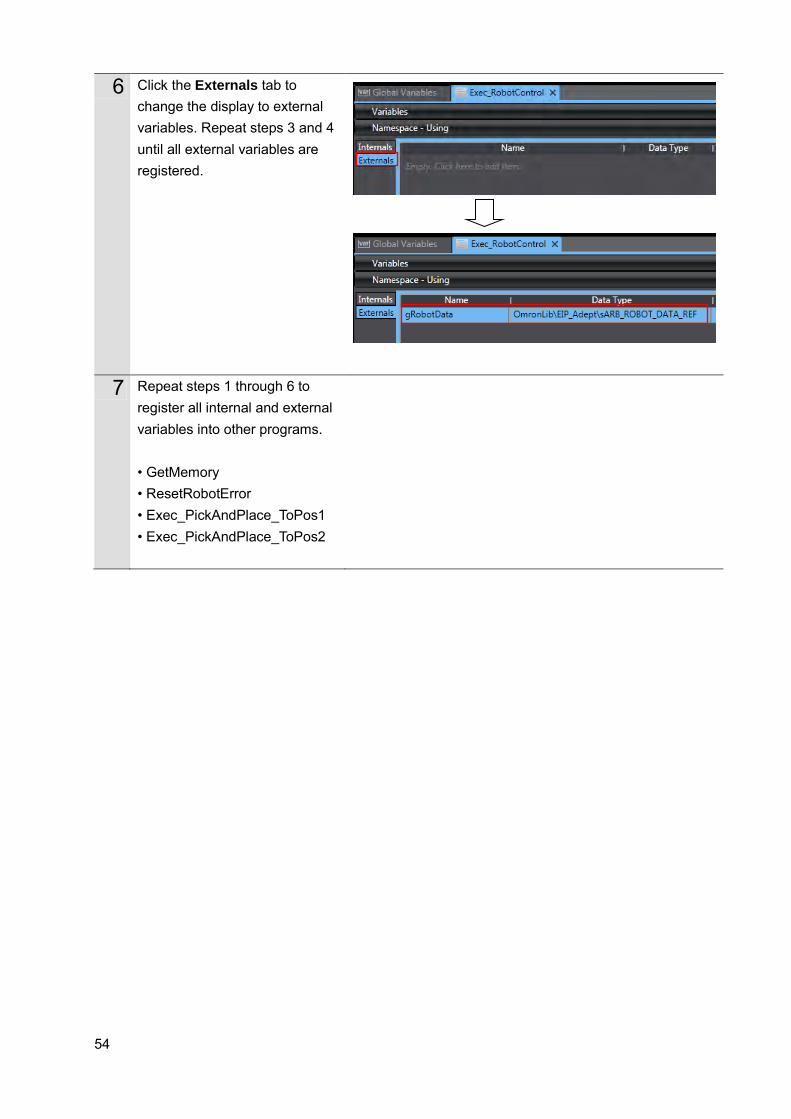
6 Click the Externals tab to change the display to external variables. Repeat steps 3 and 4 until all external variables are registered.
7 Repeat steps 1 through 6 to register all internal and external variables into other programs. • GetMemory • ResetRobotError • Exec_PickAndPlace_ToPos1 • Exec_PickAndPlace_ToPos2
55
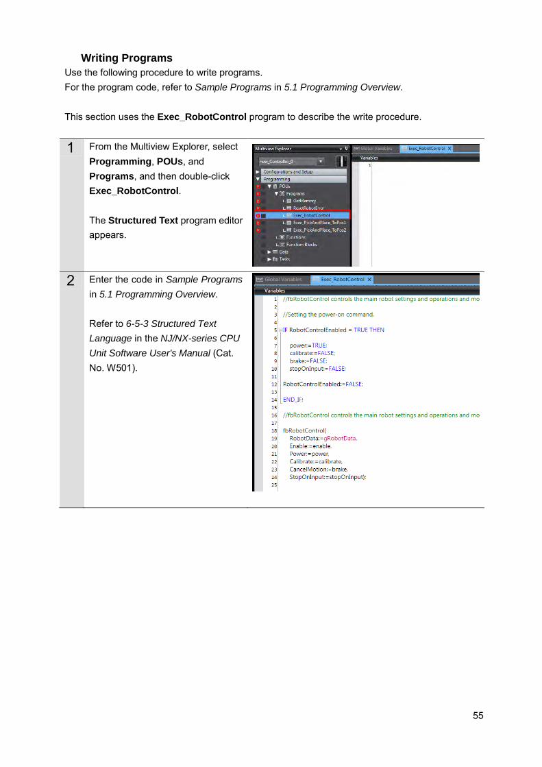
Writing Programs Use the following procedure to write programs. For the program code, refer to Sample Programs in 5.1 Programming Overview. This section uses the Exec_RobotControl program to describe the write procedure.
1 From the Multiview Explorer, select Programming, POUs, and Programs, and then double-click Exec_RobotControl. The Structured Text program editor appears.
2 Enter the code in Sample Programs in 5.1 Programming Overview. Refer to 6-5-3 Structured Text Language in the NJ/NX-series CPU Unit Software User's Manual (Cat. No. W501).
56
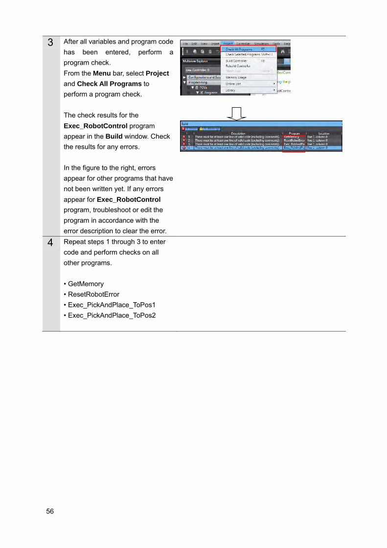
3 After all variables and program code has been entered, perform a program check. From the Menu bar, select Project and Check All Programs to perform a program check. The check results for the Exec_RobotControl program appear in the Build window. Check the results for any errors. In the figure to the right, errors appear for other programs that have not been written yet. If any errors appear for Exec_RobotControl program, troubleshoot or edit the program in accordance with the error description to clear the error.
4 Repeat steps 1 through 3 to enter code and perform checks on all other programs. • GetMemory • ResetRobotError • Exec_PickAndPlace_ToPos1 • Exec_PickAndPlace_ToPos2
57
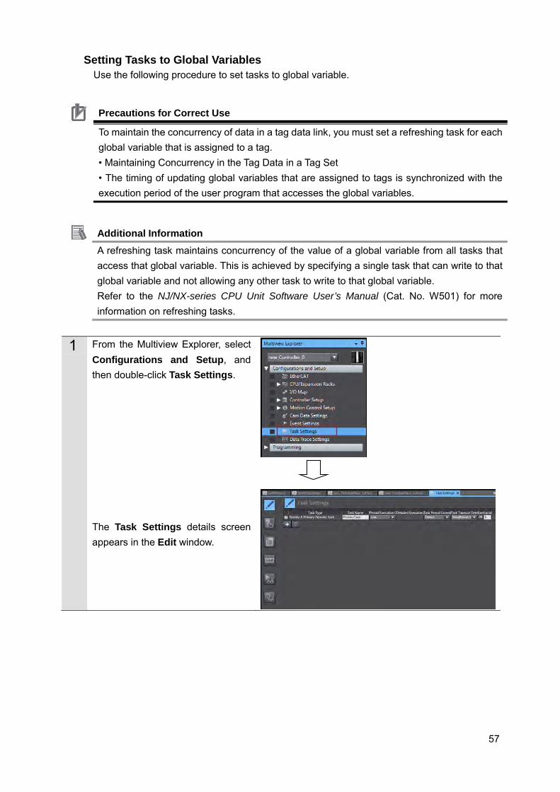
Setting Tasks to Global Variables Use the following procedure to set tasks to global variable.
Precautions for Correct Use
To maintain the concurrency of data in a tag data link, you must set a refreshing task for each global variable that is assigned to a tag. • Maintaining Concurrency in the Tag Data in a Tag Set • The timing of updating global variables that are assigned to tags is synchronized with the execution period of the user program that accesses the global variables.
Additional Information A refreshing task maintains concurrency of the value of a global variable from all tasks that access that global variable. This is achieved by specifying a single task that can write to that global variable and not allowing any other task to write to that global variable. Refer to the NJ/NX-series CPU Unit Software User’s Manual (Cat. No. W501) for more information on refreshing tasks.
1 From the Multiview Explorer, select Configurations and Setup, and then double-click Task Settings. The Task Settings details screen appears in the Edit window.
58
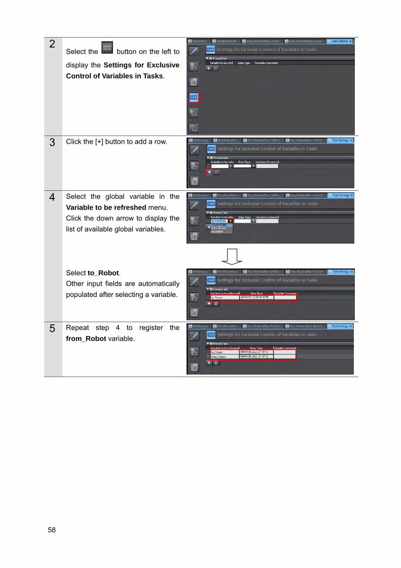
2 Select the button on the left to
display the Settings for Exclusive Control of Variables in Tasks.
3 Click the [+] button to add a row.
4 Select the global variable in the
Variable to be refreshed menu. Click the down arrow to display the list of available global variables. Select to_Robot. Other input fields are automatically populated after selecting a variable.
5 Repeat step 4 to register the
from_Robot variable.
59
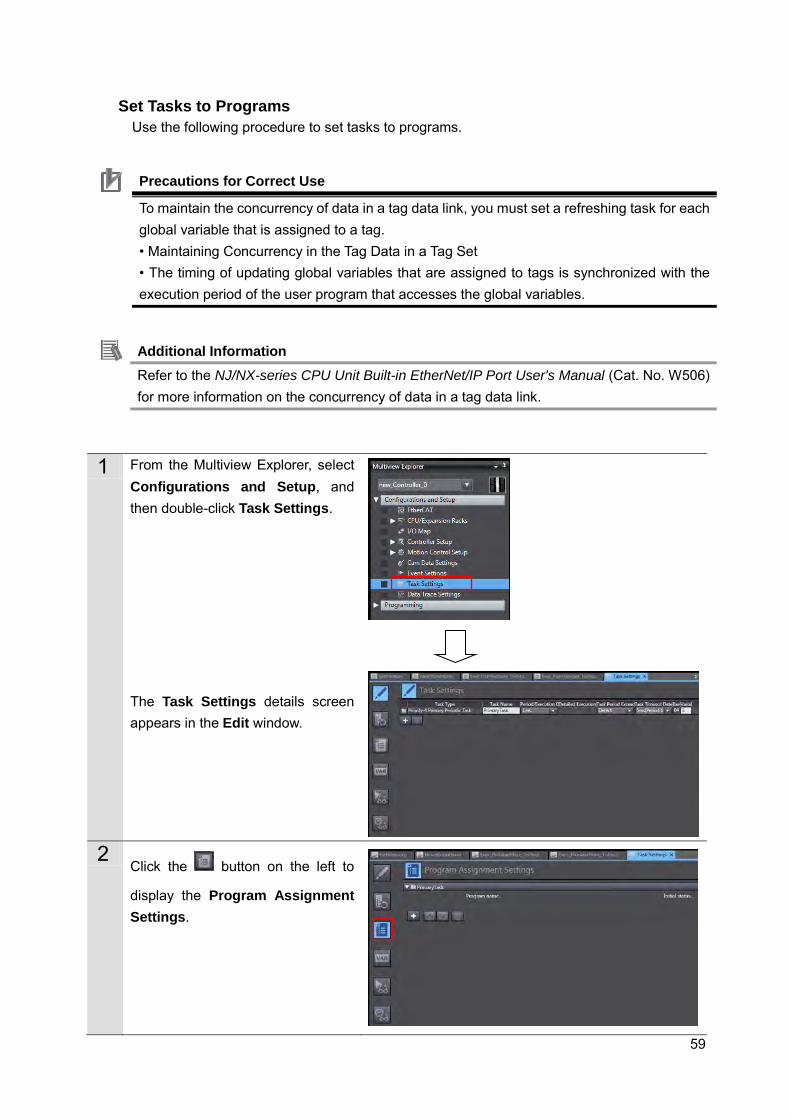
Set Tasks to Programs
Use the following procedure to set tasks to programs.
Precautions for Correct Use
To maintain the concurrency of data in a tag data link, you must set a refreshing task for each global variable that is assigned to a tag. • Maintaining Concurrency in the Tag Data in a Tag Set • The timing of updating global variables that are assigned to tags is synchronized with the execution period of the user program that accesses the global variables.
Additional Information Refer to the NJ/NX-series CPU Unit Built-in EtherNet/IP Port User's Manual (Cat. No. W506) for more information on the concurrency of data in a tag data link.
1 From the Multiview Explorer, select Configurations and Setup, and then double-click Task Settings. The Task Settings details screen appears in the Edit window.
2
Click the button on the left to
display the Program Assignment Settings.

60
3 Click the [+] button to add a row.
4 Set the program name. Click the down arrow to display the list of available programs. Select GetMemory. Select Run under the Initial Status menu.
5 Repeat steps 3 through 4 to set all
other programs. • ResetRobotError • Exec_RobotControl • Exec_PickAndPlace_ToPos1 • Exec_PickAndPlace_ToPos2
61
5.3. Debugging Programs
When function block programs are executed online, the Robot controller and the robot connected via EtherNet/IPTM may operate. Perform the robot safety risk assessment and implement safety measures as necessary, such as reducing movement speed.
Transferring Programs
Use the following procedure to make an online connection, set programs and connections, and transfer project data to Controllers.
Refer to 7.3.6 Transferring Project Data in the Machine Automation Controller NJ-series EtherNet/IPTM Connection Guide OMRON Corporation Robot controllers (ePLC connections) (Cat. No. P649).
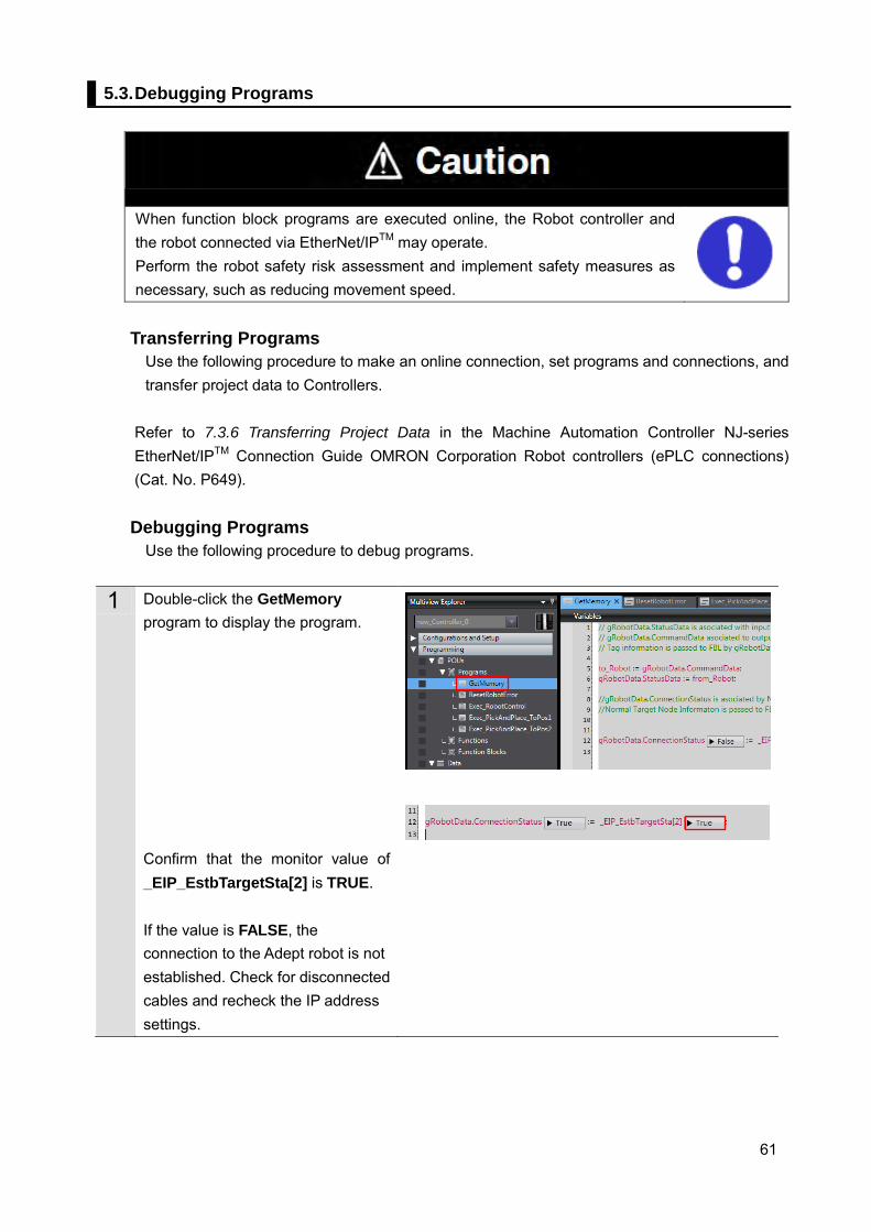
Debugging Programs
Use the following procedure to debug programs.
1 Double-click the GetMemory program to display the program. Confirm that the monitor value of _EIP_EstbTargetSta[2] is TRUE. If the value is FALSE, the connection to the Adept robot is not established. Check for disconnected cables and recheck the IP address settings.
62
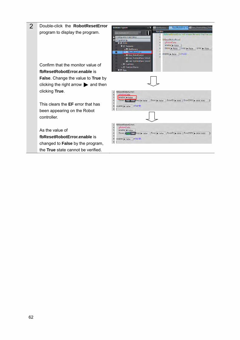
2 Double-click the RobotResetError program to display the program. Confirm that the monitor value of fbResetRobotError.enable is False. Change the value to True by clicking the right arrow and then clicking True. This clears the EF error that has been appearing on the Robot controller. As the value of fbResetRobotError.enable is changed to False by the program, the True state cannot be verified.
63
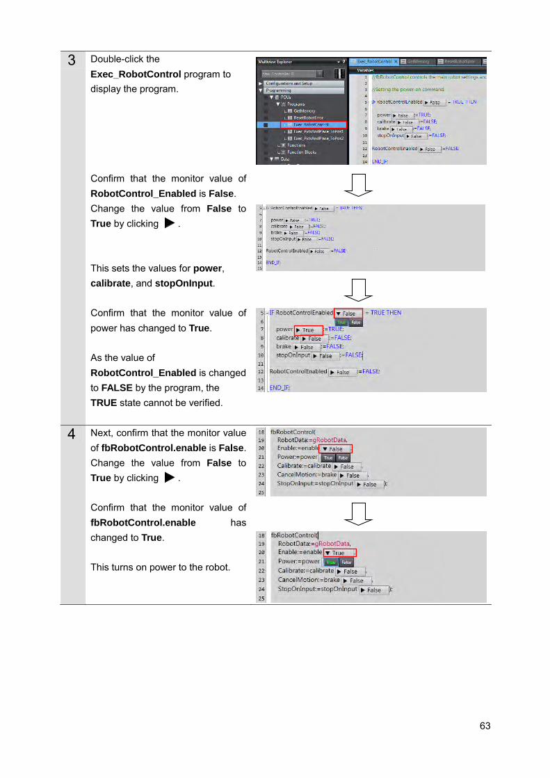
3 Double-click the Exec_RobotControl program to display the program. Confirm that the monitor value of RobotControl_Enabled is False. Change the value from False to True by clicking . This sets the values for power, calibrate, and stopOnInput. Confirm that the monitor value of power has changed to True. As the value of RobotControl_Enabled is changed to FALSE by the program, the TRUE state cannot be verified.
4 Next, confirm that the monitor value of fbRobotControl.enable is False. Change the value from False to True by clicking . Confirm that the monitor value of fbRobotControl.enable has changed to True. This turns on power to the robot.
64
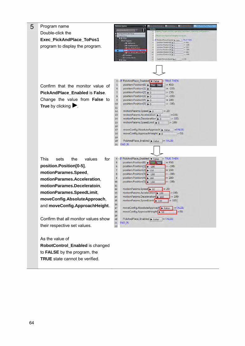
5 Program name Double-click the Exec_PickAndPlace_ToPos1 program to display the program. Confirm that the monitor value of PickAndPlace_Enabled is False. Change the value from False to True by clicking . This sets the values for position.Position[0-5], motionParames.Speed, motionParames.Acceleration, motionParames.Deceleratoin, motionParames.SpeedLimit, moveConfig.AbsoluteApproach, and moveConfig.ApproachHeight. Confirm that all monitor values show their respective set values. As the value of RobotControl_Enabled is changed to FALSE by the program, the TRUE state cannot be verified.
65
When function block programs are executed online, the Robot controller and robot connected via EtherNet/IPTM may operate. Perform the robot safety risk assessment and implement safety measures as necessary, such as reducing movement speed.
The following operations will cause the robot to move. Perform the robot safety risk assessment and implement safety measures as necessary before proceeding.
66
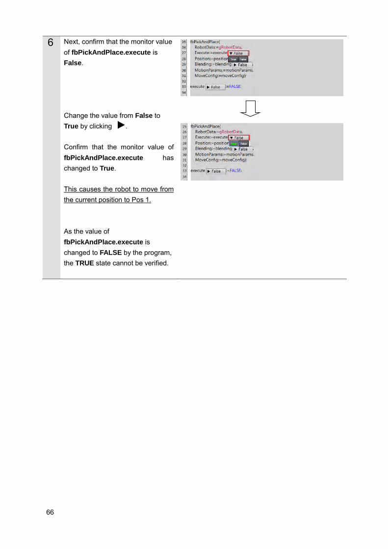
6 Next, confirm that the monitor value of fbPickAndPlace.execute is False. Change the value from False to True by clicking . Confirm that the monitor value of fbPickAndPlace.execute has changed to True. This causes the robot to move from the current position to Pos 1. As the value of fbPickAndPlace.execute is changed to FALSE by the program, the TRUE state cannot be verified.
67
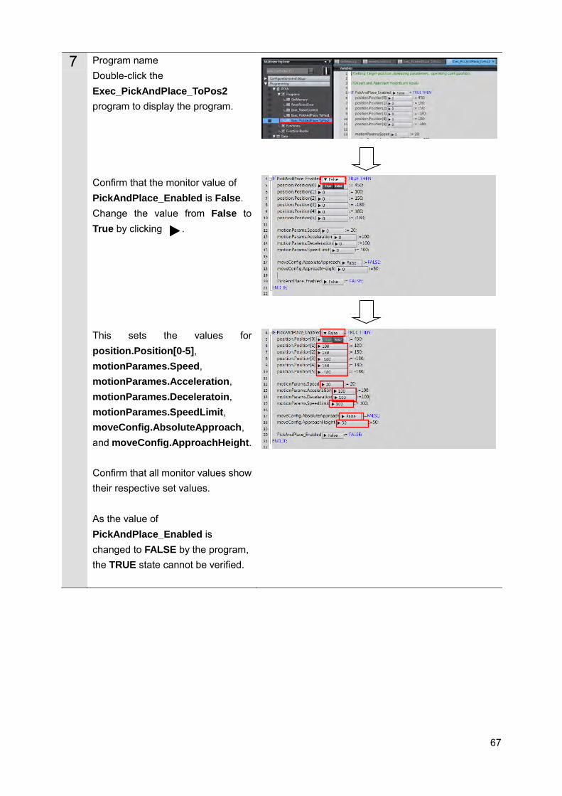
7 Program name Double-click the Exec_PickAndPlace_ToPos2 program to display the program. Confirm that the monitor value of PickAndPlace_Enabled is False. Change the value from False to True by clicking . This sets the values for position.Position[0-5], motionParames.Speed, motionParames.Acceleration, motionParames.Deceleratoin, motionParames.SpeedLimit, moveConfig.AbsoluteApproach, and moveConfig.ApproachHeight. Confirm that all monitor values show their respective set values. As the value of PickAndPlace_Enabled is changed to FALSE by the program, the TRUE state cannot be verified.
68
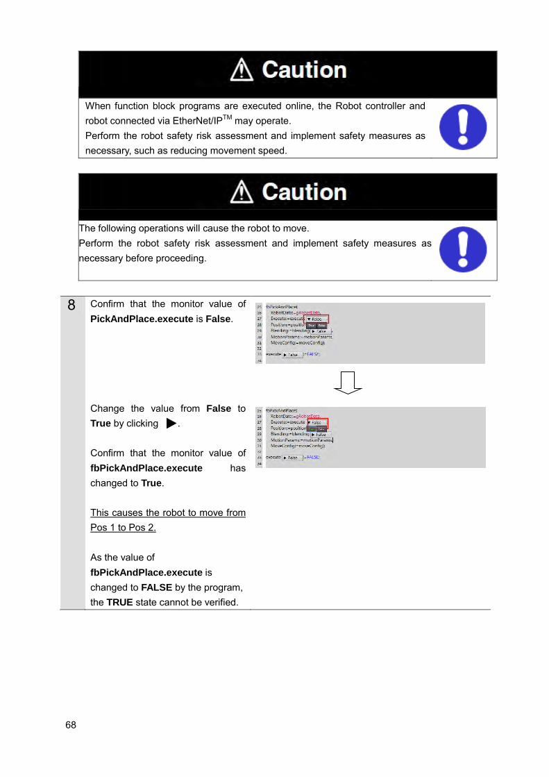
When function block programs are executed online, the Robot controller and robot connected via EtherNet/IPTM may operate. Perform the robot safety risk assessment and implement safety measures as necessary, such as reducing movement speed.
The following operations will cause the robot to move. Perform the robot safety risk assessment and implement safety measures as necessary before proceeding.
8 Confirm that the monitor value of PickAndPlace.execute is False. Change the value from False to True by clicking . Confirm that the monitor value of fbPickAndPlace.execute has changed to True. This causes the robot to move from Pos 1 to Pos 2. As the value of fbPickAndPlace.execute is changed to FALSE by the program, the TRUE state cannot be verified.
69
6. Appendix - Initialization Method This document was created on the basis that configurations are still at the default settings from the factory. If using devices for which default settings have been changed, some of the configurations presented here may not proceed according to procedure.
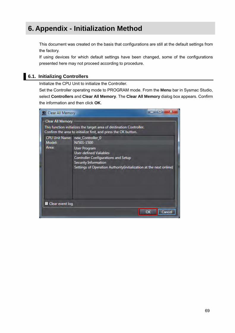
6.1. Initializing Controllers Initialize the CPU Unit to initialize the Controller. Set the Controller operating mode to PROGRAM mode. From the Menu bar in Sysmac Studio, select Controllers and Clear All Memory. The Clear All Memory dialog box appears. Confirm the information and then click OK.

2016
0516-(0516)P103-E1-01