m500 smart modem user’s reference manual user's reference.pdf · - 4 - allen-bradley df1 and...
TRANSCRIPT
M500 Smart Modem
User’s Reference Manual
Software Version 1.2.3
January 23, 2007
Copyright 1997-2007 Micro-Comm, Inc.
Table Of Contents
Introduction ....................................................................................................................................................3Allen-Bradley DF1 and Modbus Protocol Support .......................................................................................4M500 RTU Configuration Program ...............................................................................................................5
Program Installation .................................................................................................................................5RTU Information Screen ..........................................................................................................................6Configuration Parameters .........................................................................................................................7RTU Script Language Editor ...................................................................................................................9Data Table Viewer ..................................................................................................................................10Debug Terminal ...................................................................................................................................... 11
RTU Script Language Syntax ......................................................................................................................12Personality Module Memory Map ...............................................................................................................17DF1 and Modbus Store & Forward .............................................................................................................18Pass-Thru Mode ...........................................................................................................................................18COM Port Pinouts ........................................................................................................................................19
- 3 -
Introduction
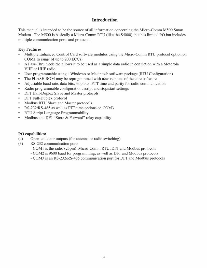
This manual is intended to be the source of all information concerning the Micro-Comm M500 Smart Modem. The M500 is basically a Micro-Comm RTU (like the S4000) that has limited I/O but includes multiple communication ports and protocols.
Key Features• Multiple Enhanced Control Card software modules using the Micro-Comm RTU protocol option on
COM1 (a range of up to 200 ECCs)• A Pass-Thru mode the allows it to be used as a simple data radio in conjuction with a Motorola
VHF or UHF radio• User programmable using a Windows or Macintosh software package (RTU Configuration)• The FLASH ROM may be reprogrammed with new versions of the core software• Adjustable baud rate, data bits, stop bits, PTT time and parity for radio communication• Radio programmable configuration, script and stop/start settings• DF1 Half-Duplex Slave and Master protocols• DF1 Full-Duplex protocol• Modbus RTU Slave and Master protocols• RS-232/RS-485 as well as PTT time options on COM3• RTU Script Language Programmability• Modbus and DF1 “Store & Forward” relay capability
I/O capabilities:(4) Open-collector outputs (for antenna or radio switching)(3) RS-232 communication ports - COM1 is the radio (25pin), Micro-Comm RTU, DF1 and Modbus protocols - COM2 is 9600 baud for programming, as well as DF1 and Modbus protocols - COM3 is an RS-232/RS-485 communication port for DF1 and Modbus protocols
- 4 -
Allen-Bradley DF1 and Modbus Protocol Support
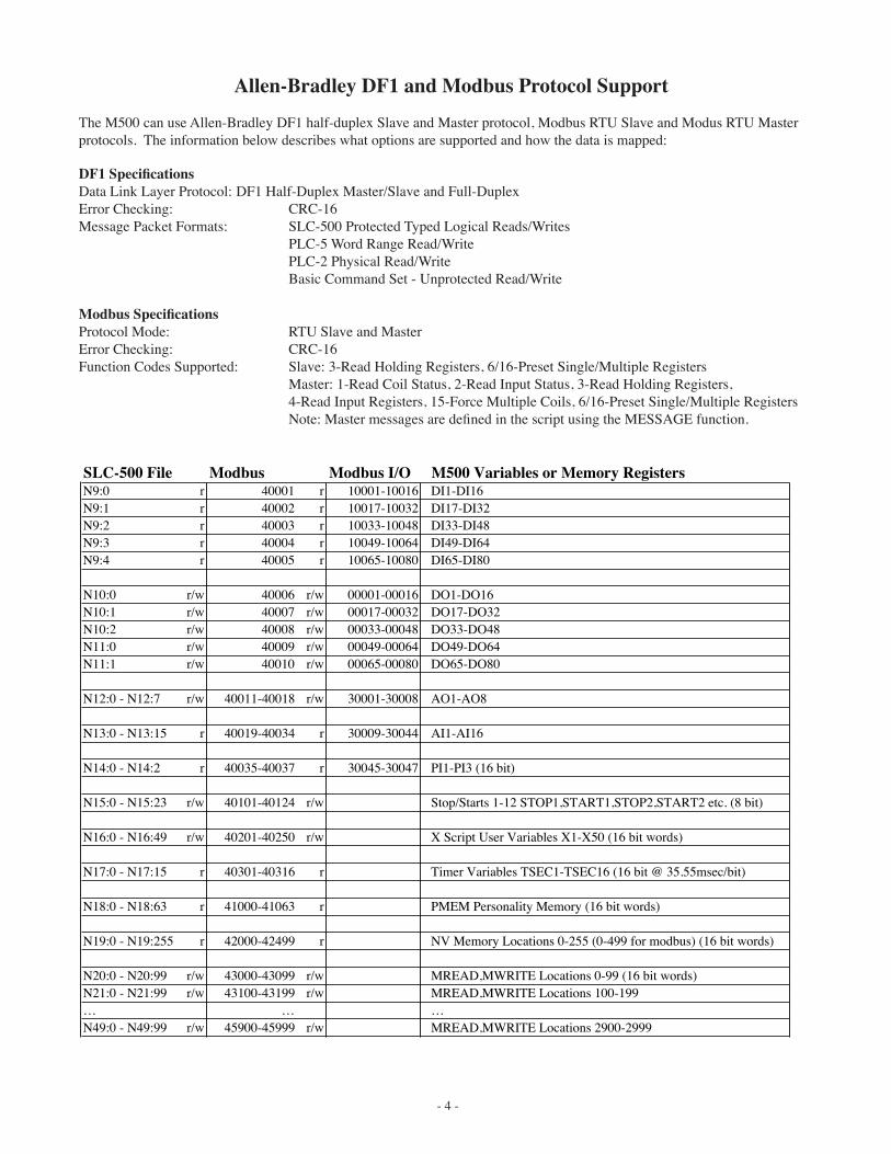
The M500 can use Allen-Bradley DF1 half-duplex Slave and Master protocol, Modbus RTU Slave and Modus RTU Master protocols. The information below describes what options are supported and how the data is mapped:
Modbus SpecificationsProtocol Mode: RTU Slave and MasterError Checking: CRC-16Function Codes Supported: Slave: 3-Read Holding Registers, 6/16-Preset Single/Multiple Registers Master: 1-Read Coil Status, 2-Read Input Status, 3-Read Holding Registers, 4-Read Input Registers, 15-Force Multiple Coils, 6/16-Preset Single/Multiple Registers Note: Master messages are defined in the script using the MESSAGE function.
DF1 SpecificationsData Link Layer Protocol: DF1 Half-Duplex Master/Slave and Full-DuplexError Checking: CRC-16Message Packet Formats: SLC-500 Protected Typed Logical Reads/Writes PLC-5 Word Range Read/Write PLC-2 Physical Read/Write Basic Command Set - Unprotected Read/Write
SLC-500 File Modbus Modbus I/O M500 Variables or Memory RegistersN9:0 r 40001 r 10001-10016 DI1-DI16N9:1 r 40002 r 10017-10032 DI17-DI32N9:2 r 40003 r 10033-10048 DI33-DI48N9:3 r 40004 r 10049-10064 DI49-DI64N9:4 r 40005 r 10065-10080 DI65-DI80
N10:0 r/w 40006 r/w 00001-00016 DO1-DO16N10:1 r/w 40007 r/w 00017-00032 DO17-DO32N10:2 r/w 40008 r/w 00033-00048 DO33-DO48N11:0 r/w 40009 r/w 00049-00064 DO49-DO64N11:1 r/w 40010 r/w 00065-00080 DO65-DO80
N12:0 - N12:7 r/w 40011-40018 r/w 30001-30008 AO1-AO8
N13:0 - N13:15 r 40019-40034 r 30009-30044 AI1-AI16
N14:0 - N14:2 r 40035-40037 r 30045-30047 PI1-PI3 (16 bit)
N15:0 - N15:23 r/w 40101-40124 r/w Stop/Starts 1-12 STOP1,START1,STOP2,START2 etc. (8 bit)
N16:0 - N16:49 r/w 40201-40250 r/w X Script User Variables X1-X50 (16 bit words)
N17:0 - N17:15 r 40301-40316 r Timer Variables TSEC1-TSEC16 (16 bit @ 35.55msec/bit)
N18:0 - N18:63 r 41000-41063 r PMEM Personality Memory (16 bit words)
N19:0 - N19:255 r 42000-42499 r NV Memory Locations 0-255 (0-499 for modbus) (16 bit words)
N20:0 - N20:99 r/w 43000-43099 r/w MREAD,MWRITE Locations 0-99 (16 bit words)N21:0 - N21:99 r/w 43100-43199 r/w MREAD,MWRITE Locations 100-199… … …N49:0 - N49:99 r/w 45900-45999 r/w MREAD,MWRITE Locations 2900-2999
- 5 -
Program Installation
Two versions of the RTU Configuration programs are available (one for Windows 95/98/NT/2000/XP and the other for Macintosh). The Windows version will be the one described and pictured in this manual, however the Macintosh version looks basically the same and the file format is identical.
To Install the Windows version, follow the steps below:
When upgrading to a new version of the program, go to the Control Panels in Windows and double-click on Add/Remove Programs. Look through the list and remove any old versions of RTU Configuration.
1) Insert the CD into the CD-ROM Drive.2) RUN the SETUP program located on the CD-ROM.3) Follow the prompts and do a typical install.4) After installation, the program icon will appear in the Start menu’s Program list.
When running the configuration program for the first time you will need to look in the communications setup screen to make sure you have the correct COM port number selected. The com port setup is located in the program’s “Setup” menu. Connection to the M500 is by means of a Null-modem cable from the computer’s RS-232 port to the M500 COM2 port.
M500 RTU Configuration Program
- 6 -
RTU Information Screen
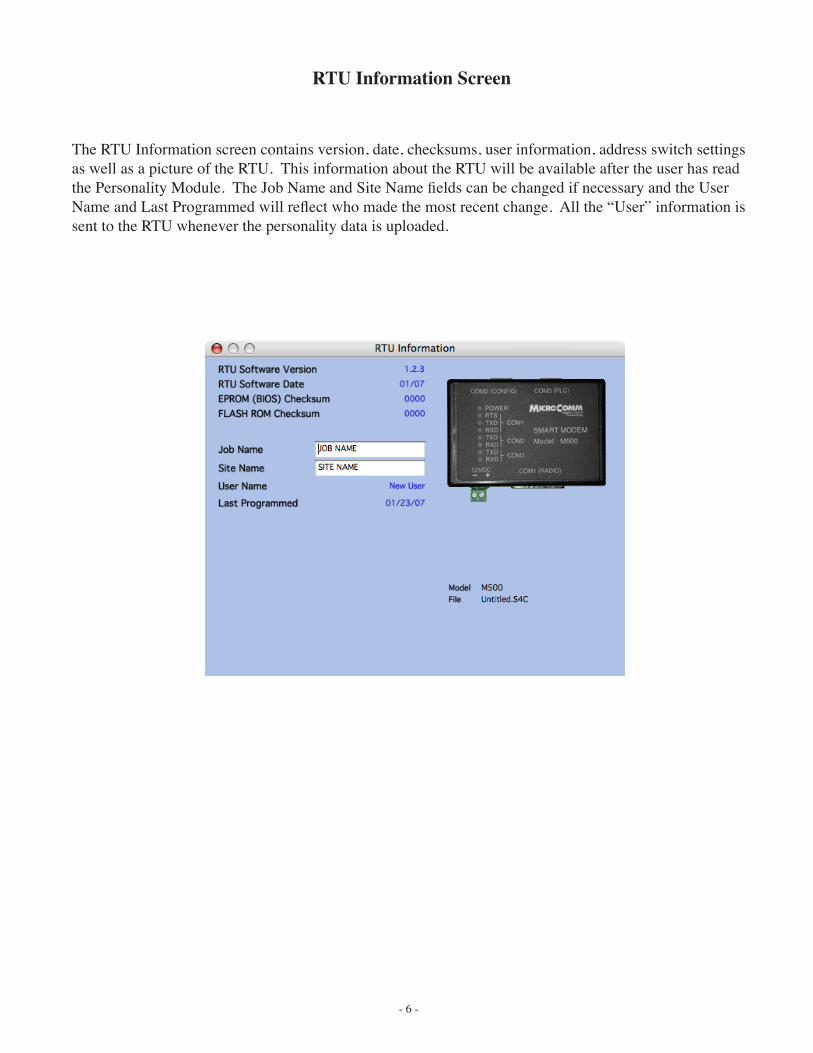
The RTU Information screen contains version, date, checksums, user information, address switch settings as well as a picture of the RTU. This information about the RTU will be available after the user has read the Personality Module. The Job Name and Site Name fields can be changed if necessary and the User Name and Last Programmed will reflect who made the most recent change. All the “User” information is sent to the RTU whenever the personality data is uploaded.
- 7 -
Configuration Parameters
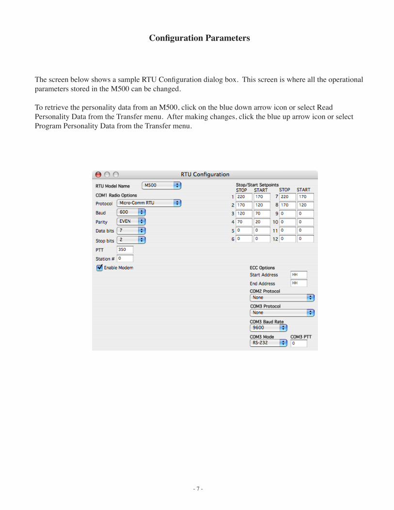
The screen below shows a sample RTU Configuration dialog box. This screen is where all the operational parameters stored in the M500 can be changed.
To retrieve the personality data from an M500, click on the blue down arrow icon or select Read Personality Data from the Transfer menu. After making changes, click the blue up arrow icon or select Program Personality Data from the Transfer menu.
- 8 -
Communication ParametersModel Name The model name of the RTU being configured is selected and shown here. This will always change to
reflect the actual RTU whenever the personality data is retrieved.
Protocol The protocol selection for the radio communications port (COM1). Options include Micro-Comm RTU (enhanced control card), Allen-Bradley DF1 Half-Duplex Slave, DF1 Half-Duplex Master, Modbus RTU Slave, Modbus RTU Master and Pass-Thru.
Baud Rate Selects the speed for the radio communications port (COM1). 110, 300, 600, 1200, 2400, 4800, 9600
and 19200 bps are supported.
Data Bits The number of data bits used by the radio port (5, 6, 7 or 8). This should be set to 7 for Micro-Comm RTU communications.
Parity Parity checking mode (Even, Odd or None). Even parity should be selected when using Micro-Comm RTU protocol.
Stop Bits The number of stop bits used by the radio port (1 or 2). This should be set to 2 for Micro-Comm RTU communications.
PTT Time in milliseconds that will occur after the radio is keyed and before the data is sent out the radio port. This should normally be set to 250 msec or more for Micro-Comm RTU communications using conventional radios. Data radios will allow for much lower PTT times (50 msec or less).
Station # For use with Modbus or DF1 protocols. This sets the station # for this RTU as used by the protocol.
Enable Modem When checked, this will enable the internal radio modem circuitry. When using a data radio this should be un-checked to prevent noise from the internal modem.
COM2 Protocol Communication protocol used for COM2. This can be None, DF1 Half-Duplex Slave, DF1 Half-Duplex Master, Modbus RTU Slave or Modbus RTU Master.
COM3 Protocol Protocol used on the COM3 RS-232/RS-485 port. This can be None, DF1 Half-Duplex Slave, DF1 Half-Duplex Master, Modbus RTU Slave or Modbus RTU Master.
COM3 Baud Rate Communications speed for the Micro-Comm I/O modules or for Modbus RTU Master communication. The default is 9600 baud.
COM3 Mode Selection for COM3 physical connection mode. This can be either RS-232 or RS-485.
COM3 PTT Time in milliseconds that will occur after RTS is turned on and before the M500 starts sending data out COM3. If set to 0, the RTS line will stay on all the time.
Stop/Start SetpointsThese setpoints can be used by the M500 in script. They can only be changed from SCADAview’s Remote Setpoint screen or from RTU Configuration.
ECC OptionsECCs are enhanced control card modules that will respond to the CTU using Micro-Comm RTU protocol.
Start Address The starting ECC address for a range of addresses. Any valid 2-character address (IH-WW) to be used. An address of HH will disable this option.
End Address The ending ECC address for a range or addresses. The M500 will respond for all addresses from Start Address to End Address.
Notes: The ECC data is located in user memory starting at 0 (mloc=3000). Ten Words of data are allocated for each ECC in the order shown for Micro-Comm Messages in the Script function reference later in this manual. If the Start and End addresses are set for more than 1 ECC in a range, more user memory locations will be allocated (i.e. ECC1=3000-3009, ECC2=3010-3019, ECC3=3020-3029 etc.)
- 9 -
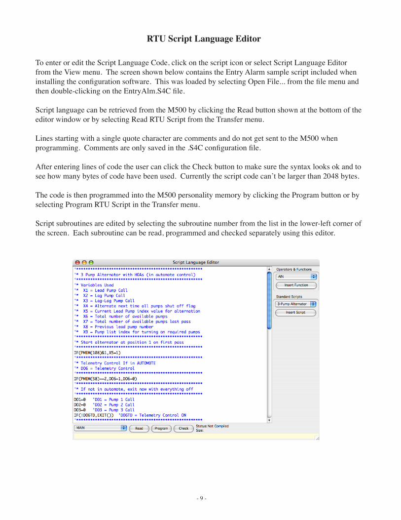
RTU Script Language Editor
To enter or edit the Script Language Code, click on the script icon or select Script Language Editor from the View menu. The screen shown below contains the Entry Alarm sample script included when installing the configuration software. This was loaded by selecting Open File... from the file menu and then double-clicking on the EntryAlm.S4C file.
Script language can be retrieved from the M500 by clicking the Read button shown at the bottom of the editor window or by selecting Read RTU Script from the Transfer menu.
Lines starting with a single quote character are comments and do not get sent to the M500 when programming. Comments are only saved in the .S4C configuration file.
After entering lines of code the user can click the Check button to make sure the syntax looks ok and to see how many bytes of code have been used. Currently the script code can’t be larger than 2048 bytes.
The code is then programmed into the M500 personality memory by clicking the Program button or by selecting Program RTU Script in the Transfer menu.
Script subroutines are edited by selecting the subroutine number from the list in the lower-left corner of the screen. Each subroutine can be read, programmed and checked separately using this editor.
- 10 -
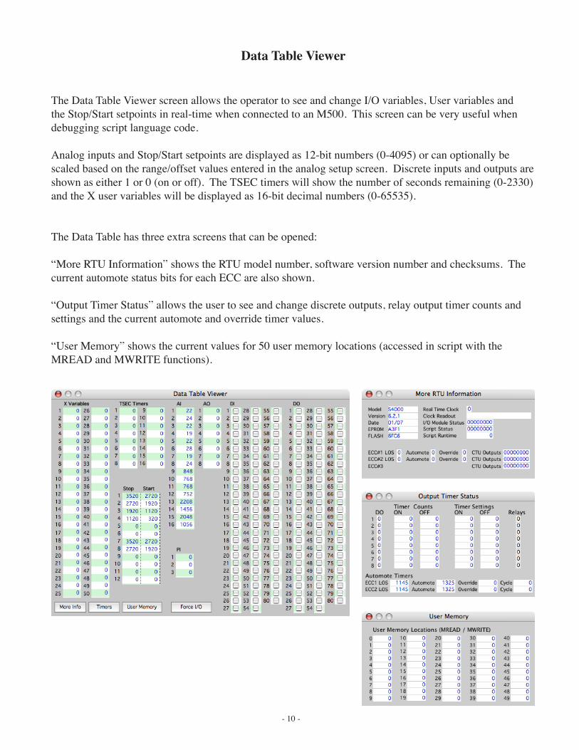
Data Table Viewer
The Data Table Viewer screen allows the operator to see and change I/O variables, User variables and the Stop/Start setpoints in real-time when connected to an M500. This screen can be very useful when debugging script language code.
Analog inputs and Stop/Start setpoints are displayed as 12-bit numbers (0-4095) or can optionally be scaled based on the range/offset values entered in the analog setup screen. Discrete inputs and outputs are shown as either 1 or 0 (on or off). The TSEC timers will show the number of seconds remaining (0-2330) and the X user variables will be displayed as 16-bit decimal numbers (0-65535).
The Data Table has three extra screens that can be opened:
“More RTU Information” shows the RTU model number, software version number and checksums. The current automote status bits for each ECC are also shown.
“Output Timer Status” allows the user to see and change discrete outputs, relay output timer counts and settings and the current automote and override timer values.
“User Memory” shows the current values for 50 user memory locations (accessed in script with the MREAD and MWRITE functions).
- 11 -
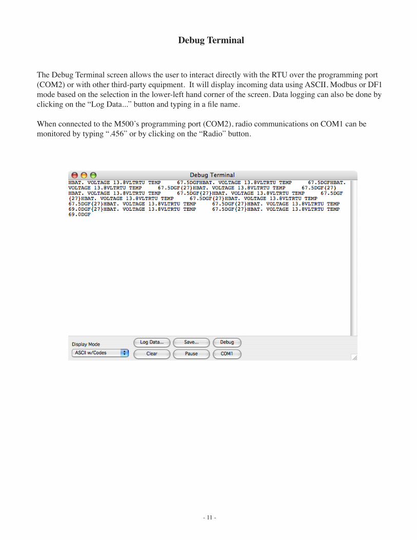
Debug Terminal
The Debug Terminal screen allows the user to interact directly with the RTU over the programming port (COM2) or with other third-party equipment. It will display incoming data using ASCII, Modbus or DF1 mode based on the selection in the lower-left hand corner of the screen. Data logging can also be done by clicking on the “Log Data...” button and typing in a file name.
When connected to the M500’s programming port (COM2), radio communications on COM1 can be monitored by typing “.456” or by clicking on the “Radio” button.
- 12 -
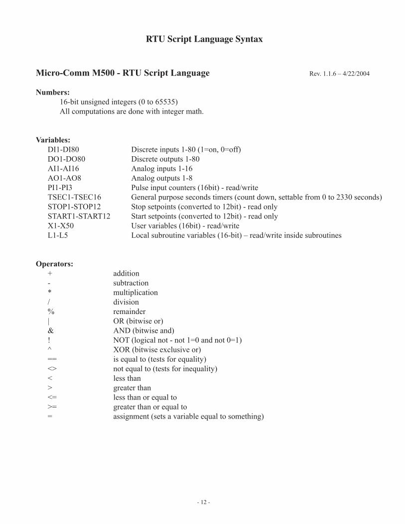
RTU Script Language Syntax
Micro-Comm M500 - RTU Script Language Rev. 1.1.6 – 4/22/2004
Numbers: 16-bit unsigned integers (0 to 65535) All computations are done with integer math.
Variables: DI1-DI80 Discrete inputs 1-80 (1=on, 0=off) DO1-DO80 Discrete outputs 1-80 AI1-AI16 Analog inputs 1-16 AO1-AO8 Analog outputs 1-8 PI1-PI3 Pulse input counters (16bit) - read/write TSEC1-TSEC16 General purpose seconds timers (count down, settable from 0 to 2330 seconds) STOP1-STOP12 Stop setpoints (converted to 12bit) - read only START1-START12 Start setpoints (converted to 12bit) - read only X1-X50 User variables (16bit) - read/write L1-L5 Local subroutine variables (16-bit) – read/write inside subroutines
Operators: + addition - subtraction * multiplication / division % remainder | OR (bitwise or) & AND (bitwise and) ! NOT (logical not - not 1=0 and not 0=1) ^ XOR (bitwise exclusive or) == is equal to (tests for equality) <> not equal to (tests for inequality) < less than > greater than <= less than or equal to >= greater than or equal to = assignment (sets a variable equal to something)
- 13 -
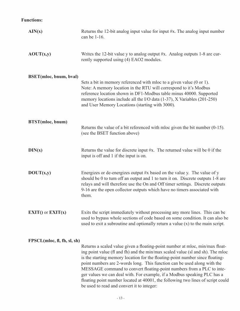
Functions:
AIN(x) Returns the 12-bit analog input value for input #x. The analog input number can be 1-16.
AOUT(x,y) Writes the 12-bit value y to analog output #x. Analog outputs 1-8 are cur-rently supported using (4) EAO2 modules.
BSET(mloc, bnum, bval) Sets a bit in memory referenced with mloc to a given value (0 or 1). Note: A memory location in the RTU will correspond to it’s Modbus reference location shown in DF1-Modbus table minus 40000. Supported memory locations include all the I/O data (1-37), X Variables (201-250) and User Memory Locations (starting with 3000).
BTST(mloc, bnum) Returns the value of a bit referenced with mloc given the bit number (0-15). (see the BSET function above)
DIN(x) Returns the value for discrete input #x. The returned value will be 0 if the input is off and 1 if the input is on.
DOUT(x,y) Energizes or de-energizes output #x based on the value y. The value of y should be 0 to turn off an output and 1 to turn it on. Discrete outputs 1-8 are relays and will therefore use the On and Off timer settings. Discrete outputs 9-16 are the open collector outputs which have no timers associated with them.
EXIT() or EXIT(x) Exits the script immediately without processing any more lines. This can be used to bypass whole sections of code based on some condition. It can also be used to exit a subroutine and optionally return a value (x) to the main script.
FPSCL(mloc, fl, fh, sl, sh) Returns a scaled value given a floating-point number at mloc, min/max float-ing point value (fl and fh) and the min/max scaled value (sl and sh). The mloc is the starting memory location for the floating-point number since floating-point numbers are 2-words long. This function can be used along with the MESSAGE command to convert floating-point numbers from a PLC to inte-ger values we can deal with. For example, if a Modbus speaking PLC has a floating point number located at 40001, the following two lines of script could be used to read and convert it to integer:
- 14 -
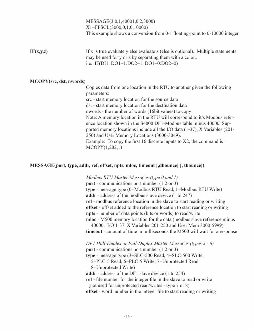
MESSAGE(3,0,1,40001,0,2,3000) X1=FPSCL(3000,0,1,0,10000) This example shows a conversion from 0-1 floating-point to 0-10000 integer.
IF(x,y,z) If x is true evaluate y else evaluate z (else is optional). Multiple statements may be used for y or z by separating them with a colon. i.e. IF(DI1, DO1=1:DO2=1, DO1=0:DO2=0)
MCOPY(src, dst, nwords) Copies data from one location in the RTU to another given the following parameters:
src - start memory location for the source data dst - start memory location for the destination data nwords - the number of words (16bit values) to copy Note: A memory location in the RTU will correspond to it’s Modbus refer-
ence location shown in the S4000 DF1-Modbus table minus 40000. Sup-ported memory locations include all the I/O data (1-37), X Variables (201-250) and User Memory Locations (3000-3049).
Example: To copy the first 16 discrete inputs to X2, the command is MCOPY(1,202,1)
MESSAGE(port, type, addr, ref, offset, npts, mloc, timeout [,dbounce] [, tbounce])
Modbus RTU Master Messages (type 0 and 1)port - communications port number (1,2 or 3)type - message type (0=Modbus RTU Read, 1=Modbus RTU Write)addr - address of the modbus slave device (1 to 247)ref - modbus reference location in the slave to start reading or writingoffset - offset added to the reference location to start reading or writingnpts - number of data points (bits or words) to read/writemloc - M500 memory location for the data (modbus slave reference minus 40000; I/O 1-37, X Variables 201-250 and User Mem 3000-5999)timeout - amount of time in milliseconds the M500 will wait for a response
DF1 Half-Duplex or Full-Duplex Master Messages (types 3 - 8)port - communications port number (1,2 or 3)type - message type (3=SLC-500 Read, 4=SLC-500 Write, 5=PLC-5 Read, 6=PLC-5 Write, 7=Unprotected Read 8=Unprotected Write)addr - address of the DF1 slave device (1 to 254)ref - file number for the integer file in the slave to read or write (not used for unprotected read/writes - type 7 or 8)offset - word number in the integer file to start reading or writing
- 15 -
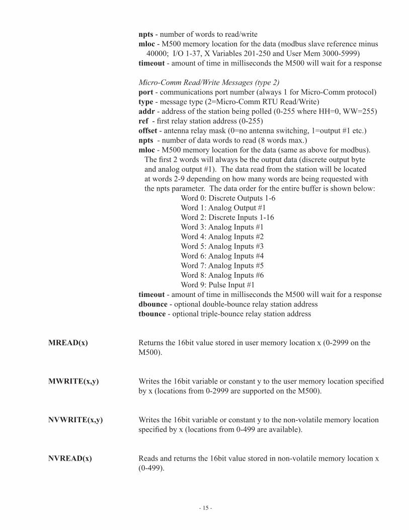
npts - number of words to read/writemloc - M500 memory location for the data (modbus slave reference minus 40000; I/O 1-37, X Variables 201-250 and User Mem 3000-5999)timeout - amount of time in milliseconds the M500 will wait for a response
Micro-Comm Read/Write Messages (type 2)port - communications port number (always 1 for Micro-Comm protocol)type - message type (2=Micro-Comm RTU Read/Write)addr - address of the station being polled (0-255 where HH=0, WW=255)ref - first relay station address (0-255)offset - antenna relay mask (0=no antenna switching, 1=output #1 etc.)npts - number of data words to read (8 words max.)mloc - M500 memory location for the data (same as above for modbus). The first 2 words will always be the output data (discrete output byte and analog output #1). The data read from the station will be located at words 2-9 depending on how many words are being requested with the npts parameter. The data order for the entire buffer is shown below: Word 0: Discrete Outputs 1-6 Word 1: Analog Output #1 Word 2: Discrete Inputs 1-16 Word 3: Analog Inputs #1 Word 4: Analog Inputs #2 Word 5: Analog Inputs #3 Word 6: Analog Inputs #4 Word 7: Analog Inputs #5 Word 8: Analog Inputs #6 Word 9: Pulse Input #1timeout - amount of time in milliseconds the M500 will wait for a responsedbounce - optional double-bounce relay station addresstbounce - optional triple-bounce relay station address
MREAD(x) Returns the 16bit value stored in user memory location x (0-2999 on the M500).
MWRITE(x,y) Writes the 16bit variable or constant y to the user memory location specified by x (locations from 0-2999 are supported on the M500).
NVWRITE(x,y) Writes the 16bit variable or constant y to the non-volatile memory location specified by x (locations from 0-499 are available).
NVREAD(x) Reads and returns the 16bit value stored in non-volatile memory location x (0-499).
- 16 -
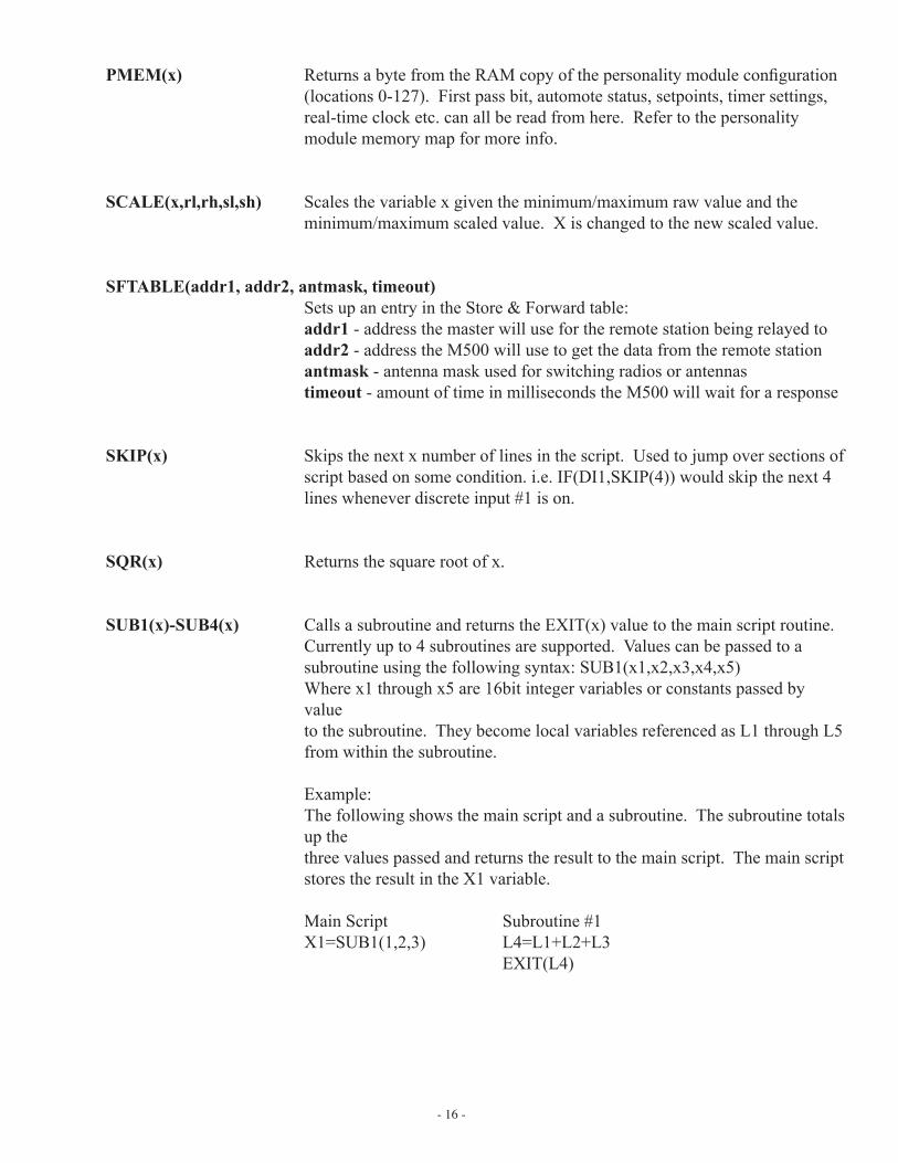
PMEM(x) Returns a byte from the RAM copy of the personality module configuration (locations 0-127). First pass bit, automote status, setpoints, timer settings, real-time clock etc. can all be read from here. Refer to the personality module memory map for more info.
SCALE(x,rl,rh,sl,sh) Scales the variable x given the minimum/maximum raw value and the minimum/maximum scaled value. X is changed to the new scaled value.
SFTABLE(addr1, addr2, antmask, timeout) Sets up an entry in the Store & Forward table: addr1 - address the master will use for the remote station being relayed to addr2 - address the M500 will use to get the data from the remote station antmask - antenna mask used for switching radios or antennas timeout - amount of time in milliseconds the M500 will wait for a response
SKIP(x) Skips the next x number of lines in the script. Used to jump over sections of script based on some condition. i.e. IF(DI1,SKIP(4)) would skip the next 4 lines whenever discrete input #1 is on.
SQR(x) Returns the square root of x.
SUB1(x)-SUB4(x) Calls a subroutine and returns the EXIT(x) value to the main script routine. Currently up to 4 subroutines are supported. Values can be passed to a subroutine using the following syntax: SUB1(x1,x2,x3,x4,x5) Where x1 through x5 are 16bit integer variables or constants passed by
value to the subroutine. They become local variables referenced as L1 through L5 from within the subroutine. Example: The following shows the main script and a subroutine. The subroutine totals
up the three values passed and returns the result to the main script. The main script stores the result in the X1 variable.
Main Script Subroutine #1 X1=SUB1(1,2,3) L4=L1+L2+L3 EXIT(L4)
- 17 -
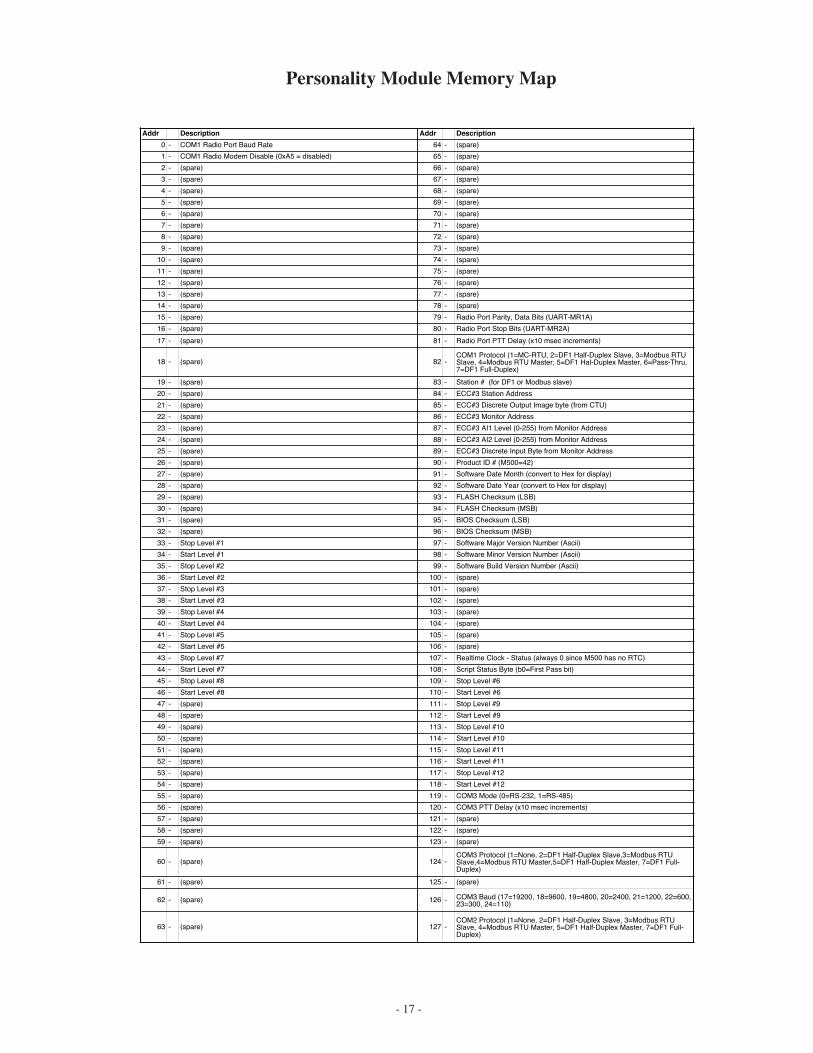
Personality Module Memory Map
Addr Description Addr Description
0 - COM1 Radio Port Baud Rate 64 - (spare)
1 - COM1 Radio Modem Disable (0xA5 = disabled) 65 - (spare)
2 - (spare) 66 - (spare)
3 - (spare) 67 - (spare)
4 - (spare) 68 - (spare)
5 - (spare) 69 - (spare)
6 - (spare) 70 - (spare)
7 - (spare) 71 - (spare)
8 - (spare) 72 - (spare)
9 - (spare) 73 - (spare)
10 - (spare) 74 - (spare)
11 - (spare) 75 - (spare)
12 - (spare) 76 - (spare)
13 - (spare) 77 - (spare)
14 - (spare) 78 - (spare)
15 - (spare) 79 - Radio Port Parity, Data Bits (UART-MR1A)
16 - (spare) 80 - Radio Port Stop Bits (UART-MR2A)
17 - (spare) 81 - Radio Port PTT Delay (x10 msec increments)
18 - (spare) 82 -COM1 Protocol (1=MC-RTU, 2=DF1 Half-Duplex Slave, 3=Modbus RTUSlave, 4=Modbus RTU Master, 5=DF1 Hal-Duplex Master, 6=Pass-Thru,7=DF1 Full-Duplex)
19 - (spare) 83 - Station # (for DF1 or Modbus slave)
20 - (spare) 84 - ECC#3 Station Address
21 - (spare) 85 - ECC#3 Discrete Output Image byte (from CTU)
22 - (spare) 86 - ECC#3 Monitor Address
23 - (spare) 87 - ECC#3 AI1 Level (0-255) from Monitor Address
24 - (spare) 88 - ECC#3 AI2 Level (0-255) from Monitor Address
25 - (spare) 89 - ECC#3 Discrete Input Byte from Monitor Address
26 - (spare) 90 - Product ID # (M500=42)
27 - (spare) 91 - Software Date Month (convert to Hex for display)
28 - (spare) 92 - Software Date Year (convert to Hex for display)
29 - (spare) 93 - FLASH Checksum (LSB)
30 - (spare) 94 - FLASH Checksum (MSB)
31 - (spare) 95 - BIOS Checksum (LSB)
32 - (spare) 96 - BIOS Checksum (MSB)
33 - Stop Level #1 97 - Software Major Version Number (Ascii)
34 - Start Level #1 98 - Software Minor Version Number (Ascii)
35 - Stop Level #2 99 - Software Build Version Number (Ascii)
36 - Start Level #2 100 - (spare)
37 - Stop Level #3 101 - (spare)
38 - Start Level #3 102 - (spare)
39 - Stop Level #4 103 - (spare)
40 - Start Level #4 104 - (spare)
41 - Stop Level #5 105 - (spare)
42 - Start Level #5 106 - (spare)
43 - Stop Level #7 107 - Realtime Clock - Status (always 0 since M500 has no RTC)
44 - Start Level #7 108 - Script Status Byte (b0=First Pass bit)
45 - Stop Level #8 109 - Stop Level #6
46 - Start Level #8 110 - Start Level #6
47 - (spare) 111 - Stop Level #9
48 - (spare) 112 - Start Level #9
49 - (spare) 113 - Stop Level #10
50 - (spare) 114 - Start Level #10
51 - (spare) 115 - Stop Level #11
52 - (spare) 116 - Start Level #11
53 - (spare) 117 - Stop Level #12
54 - (spare) 118 - Start Level #12
55 - (spare) 119 - COM3 Mode (0=RS-232, 1=RS-485)
56 - (spare) 120 - COM3 PTT Delay (x10 msec increments)
57 - (spare) 121 - (spare)
58 - (spare) 122 - (spare)
59 - (spare) 123 - (spare)
60 - (spare) 124 -COM3 Protocol (1=None, 2=DF1 Half-Duplex Slave,3=Modbus RTUSlave,4=Modbus RTU Master,5=DF1 Half-Duplex Master, 7=DF1 Full-Duplex)
61 - (spare) 125 - (spare)
62 - (spare) 126 - COM3 Baud (17=19200, 18=9600, 19=4800, 20=2400, 21=1200, 22=600,23=300, 24=110)
63 - (spare) 127 -COM2 Protocol (1=None, 2=DF1 Half-Duplex Slave, 3=Modbus RTUSlave, 4=Modbus RTU Master, 5=DF1 Half-Duplex Master, 7=DF1 Full-Duplex)
- 18 -
DF1 and Modbus Store & Forward
The M500 can also be used to relay information using Modbus or DF1 protocols by use of a Store & Forward table. COM1 should be set for either Modbus RTU Slave or DF1 Half-Duplex Slave for this option to work.
The script command that sets an entry into the Store & Forward Table is shown below:
SFTABLE(addr1, addr2, antmask, timeout) addr1 address the master will use for the remote station being relayed to addr2 address the M500 will use to get the data from the remote station antmask antenna mask used for switching radios or antennas timeout amount of time in milliseconds the M500 will wait for a response
DF1 Protocol Notes: When the M500 uses DF1 for Store & Forward, it will immediately respond to the DF1 Master (usually a SLC-500 PLC) with the most recent data in it’s buffer for the requested remote site. The DF1 Master must then remain quiet for a period of time so that the read/write command can take place with the remote site. Because of the way DF1 Store & Forward is handled, data read from a remote site should always be from the same block of data. The M500’s buffer is currently set for up to 50 words of data read from up to 10 remote “relayed to” sites.
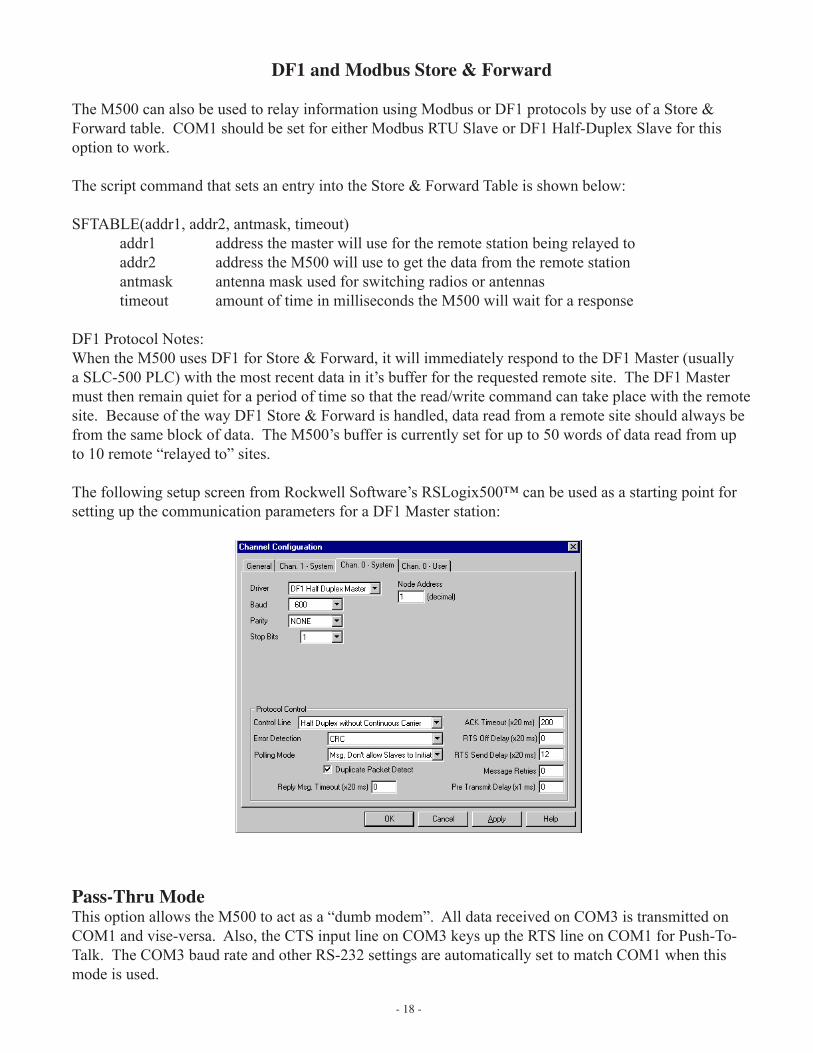
The following setup screen from Rockwell Software’s RSLogix500™ can be used as a starting point for setting up the communication parameters for a DF1 Master station:
Pass-Thru ModeThis option allows the M500 to act as a “dumb modem”. All data received on COM3 is transmitted on COM1 and vise-versa. Also, the CTS input line on COM3 keys up the RTS line on COM1 for Push-To-Talk. The COM3 baud rate and other RS-232 settings are automatically set to match COM1 when this mode is used.
- 19 -
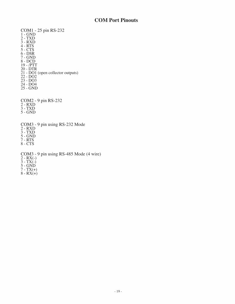
COM Port Pinouts
COM1 - 25 pin RS-2321 - GND2 - TXD3 - RXD4 - RTS5 - CTS6 - DSR7 - GND8 - DCD19 - /PTT20 - DTR21 - DO1 (open collector outputs)22 - DO223 - DO324 - DO425 - GND
COM2 - 9 pin RS-2322 - RXD3 - TXD5 - GND
COM3 - 9 pin using RS-232 Mode2 - RXD3 - TXD5 - GND7 - RTS8 - CTS
COM3 - 9 pin using RS-485 Mode (4 wire)2 - RX(-)3 - TX(-)5 - GND7 - TX(+)8 - RX(+)