m38a1 carb chapt9tm9-1826a
TRANSCRIPT
CHAPTER 9,
TYPE Y-S CARBURETOR,. MODEL 6375 .
Section I. DESCRIPTION AND DATA
89. Description
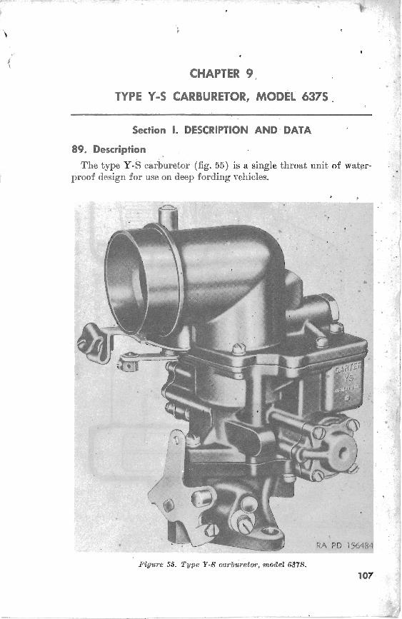
The type Y-S carburetor (fig. 55) is a single throat unit of water- .
proof design for use on deep fording vehicles.
Figure 55. Type Y-8 cwburetor, model 687s.
107
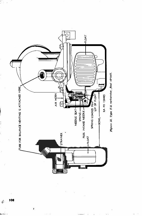
W. Floot Circuit (fk. 56)
The operation of the float circuit is conventional (par. 13). The . fuel intake needle is hollow to permit the insertion of a spring and pin. The lip of the float beam on this spring loaded pin, which serves to prevent flooding due to needle chattp, caused by excessive vibra- tion. The bowl is "balance" vented by means of an external tube which connects the air horn to the air cleaner. I
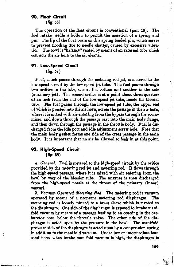
91. Low-Speed Circuit (fig. 67)
Fuel, which passes through the metering rod jet, is metered to the , low-speed circuit by the low-speed jet tube. .The fuel passes through I
two orifices in the tube, one at the bottom and another in the side (auxiliary jet). The second orifice is at a point about three-quarters of an inch from the end of the low-speed jet tube, inside the bleeder tube. The fuel passes through the low-speed jet tube, the upper end of which is pressed into the air horn, across the paasage in the air horn, where i t is mixed with air entering from the bypass through the econo- mizer, and down through the passage cast into the main body flange, and then down through the passage in the throttle body. Fuel is dia- l
charged from the idle port and idle adjustment screw hole. Note that the main body gasket forms one side of the cross passage in the main body. It is important.that no air be allowed to leak in J this point.
I
92. High-speed Circuit , I
(fig* 68) I
a. B w J : Fuel is metered to the high-speed circuit by the orifice provided by the metering rod jet and metering rod. I t flows through the high-speed passage, where it is mixed with air entering from the bowl by way of the bleeder tube. The mixture is then discharged from the high-speed nozzle at the throat of the primary (inner) venturi. 6. Vmmm Operated Metering Rod. The metering rod is vacuum
operated by means of a neoprene metering rod diaphragm. The metering rod is l w l y pinned to a brass sleeve which is riveted to the diaphragm. One side of the diaphragm is exposed to intake mani- fold vacuum by means of a p m g e leading to an opening in the car- buretor bore, below the throttle valve. The other side of the dia- phragm is acted upon by the pressure in the bowl. The manifold preasure side of the diaphragm is acted upon by a compression spring in addition to the manifold vaclium. Under low or intermediate load conditions, when intake manifold vacuum is high, the diaphragm is
Figure 67. Tgpe Y-61 owburetor, knwpsad ohvidt.
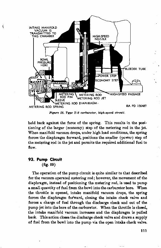
Figure 58. Type Y-8 carburetor, high-speed cirouft.
held back against the force of the spring. This results in the p i - tioning of the larger (economy) step of the metering rod in the jet. When manifold vacuum drops, under high load conditions, the spring forces the diaphragm forward, positions the smaller (power) step of the metering md in the jet and permits the required additional fuel to flow.
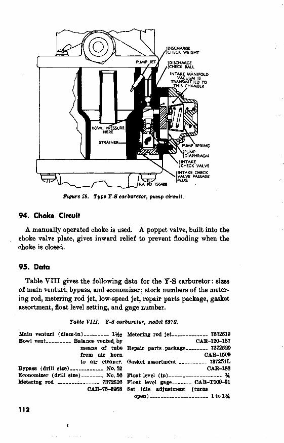
93. Pump Circuit (fig* 59)
The operation of the pump circuit is quite similar to that described for the vacuum operated metering rod; however, the movement of the diaphragm, instead of positioning the metering rod, is used to pump a small quantity of fuel fmm the bowl into the carburetor bore. When the throttle is opened, intake manifold vacuum drops, t.he spring forces the diaphragm for'ward, closing the intake check valve and forcas a charge of fuel through the discharge check and out of the pump jet into the bore of the carburetor. When the throttle is closed, the intake manifold vacuum increases and the diaphragm is pulled back. This action closes the discharge check valve and draws a supply of fuel from the bowl into the pump via the open intnke check valve.
DISCHARGE CHECK WEIGHT
INTAKE CHECK
Figclre 58. Type Y-61 carburetor, pump ctrouit.
94. Choke Circuit
A manually operated choke is used. A poppet valve, built into the choke valve plate, gives inward relief to prevent flooding when the choke is closed.
95. Data
Table VIII gives the following data for the Y-S carburetor: sizes of main venturi, bypass, and economizer; stock numbers of the meter- ing rod, metering rod jet, low-speed jet, repair parts package, gasket assortment, float level setting, and gage number.
Tabte VIII . Y-61 carburetor, ..no&et 65761.
Main ventnri (diam-in) ,,-- --,,- 1342 Bowl vent -----,-,, Balance vents by
means of tube from air horn to air cleaner.
Bypass (drill size) -----,,,,-,- No. 52 Economizer (drill size) ,,-----, No. 66 Metering rod ,,-,,-----,--,- 7372526
CAR-75-5958
Metering rod jet --,,--------- 7872519 CAR-IS157
Repair parts package ,,,,--,- 73725m CAR-1M)9
Gasket assortment ,,-------- 787251L CAR188
Float level (in) -----,------------- Yi Float level gage -----,- CAR-T100-81 Set idle adjustment (turn6
open)-------------,------- 1 to lYi
Section II. REBUILD OF TYPE Y-S CARBURETORS
96. General
Most carburetor troubles are caused by dirt which restricts jets and air bleeds or interferes with the free operation of moving parts. The instructions which follow cover the procedures for completely clean- ing and adjusting the carburetor. If the carburetor is to be rebuilt, it is advised that a complete repair parts package be installed. Obviously, if this is done, those parts which are to be replaced need not be cleaned and inspected. Whenever the' carburetor is serviced a new gasket m r t m e n t should be installed.
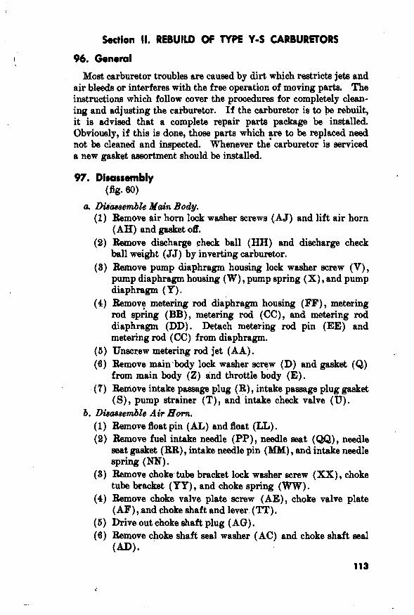
a D&hsembk blah Body. (1) Remove air horn lock washer screws (.AJ) and lift air horn
(AH) and gasket off. (2) Bemove discharge check ball (HH) and discharge check
ball weight (JJ) by inverting carburetor. (3) h o v e pump diaphragm housing lock washer screw (V),
pump diaphragm housing (W) , pump spring (X) , and pump diaphragm (Y).
(4) Remov? metering rod diaphragm housing (FF), metering rod spring (BB), metering rod (CC), and metering rod diaphragm (DD). Detach metering rod pin (EE) and metering rod (CC) from diaphragm.
(5) Unscrew metering rod jet (AA). (6) Remove mainhdy lock washer screw (D) and gasket (Q)
from main body (2) and throttle body (E). (7) Remove intake p a a g e plug (R ) , intake passage plug gasket
(S), pump strainer (T), and intake check valve (U). b. Dbaasembte Air Eorn.
(1) Bemove float pin (AL) and float (LL) . (2) Remove fuel intake needle (PP), needle mat (QQ), needle
seat gasket (RR), intake needle pin (MIM) , and intake needle S P ~ ~ W (NN)
(3) Remove choke tube bracket lock washer screw (XX) , choke tube bracket (YY) , and choke spring (WW) .
(4) Remove choke valve plate screw (AE), choke valve plate (AF) , and choke shaft and lever ('IT).
(5) Drive out choke shaft plug ( AGt) . (6) Bemove choke shaft seal washer (AC) and choke shaft seal
(A")
A-THROTTLE VALVE PLATE SCREW
&THROTTLE VALVE PLATE C-EXPANSION PLUG D-MAIN BODY LOCK WASHER - - - - - - - -
SCREW E-THROTTLE F-THROTTLE G-THROTTLE
WASHER H-THROTTLE
LEVER J-THROTTLE
BODY SHAFT SEAL SHAFT SEAL
SHAFT AND
ADJUSTMENT SCREW
K-IDLE PORT PLUG L-IDLE ADJUSTMENT SCREW
DUST SEAL M-IDLE ADJUSTMENT SCREW
DUST SEAL WASHER N-IDLE ADJUSTMENT SCREW
SPRING P-IDLE ADJUSTMENT SCREW -MAIN BODY GASKET &INTAKE PASSAGE PLUG S-INTAKE PASSAGE PLUG
GASKET T-PUMP STRAINER
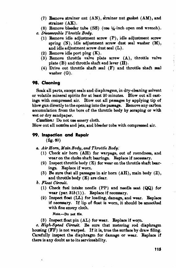
U-INTAKE CHECK VALVE RR-NEEDLE SEAT GASKET V-DIAPHRAGM HOUSING *BLEEDER TUBE
LOCK WASHER SCREW TT-CHOKE SHAFT AND LEVER W-PUMP DIAPHRAGM HOUS- UU-CHOKE WIRE CLAMP
ING SCREW X-PUMP SPRING VV-TUBE CLAMP NUT --
Y-PUMP DIAPHRAGM WW-CHOKE SPRING %MAIN BODY
AA-METERING ROD J E T BB-METERING ROD SPRING CC-METERING ROD D W M E T E R I N G R O D D I A -
PHRAGM EE--METERING ROD PIN F F - M E T E R I N G R O D D I A -
PHRAGM HOUSING * GG--MAIN BODY LOCK WASHER
SCREW HH-DISCHARGE CHECK BALL
JJ-DISCHARGE CHECK BALL - - - - - - - - - - - WEIGHT
KK-Al'R HORN GASK,ET L L F L O A T
MM-INTAKE NEEDLE PIN NN-INTAKE NEEDLE SPRING PP-FUEL INTAKE NEEDLE QQ-NEEDLE SEAT
XX-CHOKE T U B E . BRACKET LOCK WASHER SCREW
YY-CHOKE TUBE BRACKET Z2-TUBE CLAMP AB-TUBE CLAMP SCREW AC-CHOKl3 M I A I T SEAL WA8HER AD-CHOKE SHAFT SEAL AE--CHOKE VALVE PLATE
SCREW AF-CHOKE VALVE PLATE AG-CHOKE SHAFT PLUG AH-AIR HORN AJ-AIR HORN LOCK WASHER
SCREW AK-STRAINER AL-FLOAT PIN
AM-STRAINER NUT GASKET AN-STRAINER NUT
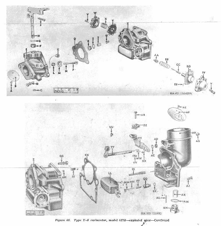
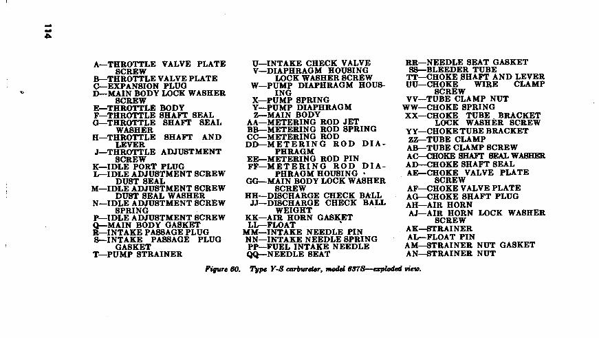
Figure 60. Type Y-8 carburetor, model GS7S-ezploded @em-Continued '$ - -
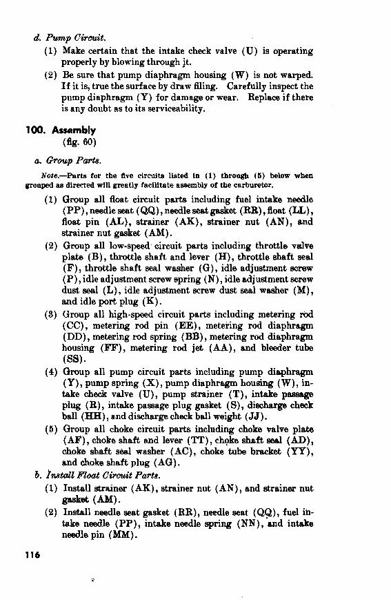
(7) Remove strainer nut (AN), sh iner nut gasket (AM), and strainer ( AK) .
(8) Remove bleeder tube (SS) (use %-inch open end wrench). a. zX9a~8eptbZe Throttle Body.
(1) Bemove idle adjustment acrew (P), idle adjustment screw spring (N), idle adjustment screw dust seal washer (M), and idle adjustment screw dust seal (L).
(2) h o v e idle port plug (K) . (3) Remove throttle valve plate screw (A), throttle valve
plate (B) and throttle shaft and lever (H) . (4) Drive out throttle shaft seal (F) and throttle shaft seal
washer ((3).
98. Cleaning
Soak all parts, except seals and diaphragms, in dry-cleaning solvent or volatile mineral spirits for at least 20 minutes. Blow out all cast- ings with compressed air. Blow out a11 passap by applying tip of blow gun directly to the opening into the paasage. Remove any carbon accumulation from the bore of the throttle body by scraping or with wet or dry sandpaper.
Caution: Do not use emery cloth. Blow out all nozzles and jeta, and bleeder tube with compressed air.
99. Inspection and Repoir (fig* 60)
a. A& Horn, Main Body, a d Throttik Body: (1) Check air horn (AH) for warpage, out of roundness, and
wear on the choke shaft bearings. Replace if necessary. (2) Inspect throttle body (E) for wear on the throttle shah bear-
ings. Replace if worn. (3) Be sure that all passages in air horn (AH), main body (Z),
and throttle body (E) are clear. b. Fbat CiTCUit.
(1) Check fuel intake needle (PP) and needle s a t (a) for wear (par. 816 (1) ) . Replace if necessary.
(2) Inspect float (LL) for loading, damage, and wear. Beplace if necessary. If lip of float is worn, it should be smoothed with fine emery cloth.
Note.-Do not ffle.
(8) Inspect float pin (AL) for wear. Beplace if wop. o. High-Speed Cimit. Be sure that metering rad diaphragm
homing (FF) is not warped. If it is, true the surface by draw filing. Carefully inspect the diaphragm for damage or wear. Replace if there is any doubt as to its serviceability.
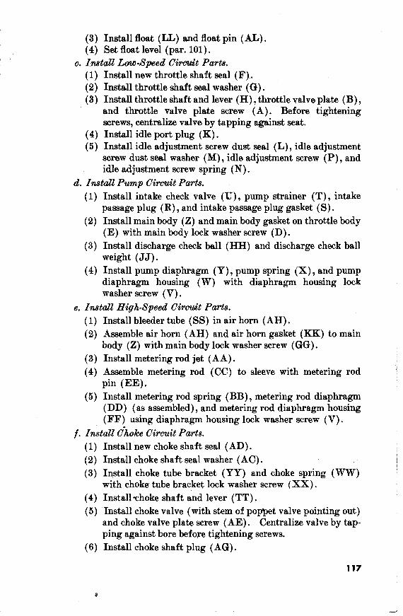
d. Pump Circuit. (1) Make certain that the intake check valve (U) is operating
properly by blowing through jt. (2) Be sure that pump diaphragm housing (W) is not warped.
If it. is, true the surface by draw filing. Carefully inspect the pump diaphragm ( Y) for damage or %*ear. Replace if there is any doubt as to its serviceability.
Note.-Parts for the five circuits listed in (1) through (5) below when grouped as directed will great1 y facilitate assembly of the carburetor.
(1) Group all float circuit parts including fuel intake needle (PP) , needle seat (QQ) , needle seat gasket (RR) , float (LL) , float pin (AL), strainer (AK), strainer nut (AN), and strainer nut gasket (AM).
(2) Group all low-speed- circuit parts including throttle vdve plate (B), throttle shaft and lever (H), throttle shaft seal (F), throttle shaft seal washer (G), idle adjustment screw (P) , idle adjustment screw spring (N), idle adjustment screw dust seal (L), idle adjustment s c m dust seal washer (M), and idle port plug (K) .
(3) Group all high-speed circuit parts including metering rod (CC), metering rod pin (EE), metering rod diaphragm (DD), metering rod spring (BB), metering rod diaphragm housing (FF), metering rod jet (AA), and bleeder tube (SW*
(4) Group all pump circuit parts including pump diaphragm (Y) , pump spring (X), pump diaphragm housing (W) , in- take check valve (U), pump strainer (T), intake passage plug (R), intake passage plug gasket (S), discharge check ball (HH ) , and discharge check ball wight (JJ ) .
(5) Group all choke circuit parts including choke valve plate ( AF) , choke shaft and lever ( TT ) , choke shaft seal (AD), choke shaft seal washer (AC), choke tube bracket (YY), and choke shaft plug (AG) .
b. fmtdi? Float Circuit Parts. (1) Install strainer (AK), strainer nut (AN), and strainer nut
w e t (Am (2) Install needle seat gasket (RR), needle seat (QQ), fuel in-
take needle (PP), intake needle spring (NN), and intake needle pin (MM).
(3) Install float (LL) and float pin (AL) . (4) Set float level (par. 101).
c. Install Lao-Speed C i r d t Parts. (1) Install new throttle shaft seal (F ) . (2) Install throttle shaft seal washer (G) . (3) Install throttle shaft and lever (H) , throttle valve plate (B) ,
and throttle valve plate screw (A). Before tightening screws, centralize valve by tapping against seat.
(4) Install idle port plug (K) . (5) Install idle adjustment screw dust seal (L), idle adjustment
screw dust seal washer (M) , idle adjustment screw (P) , and idle adjustment screw spring (N) .
a?. Install Pump Circuit Parts. (1) Install intake check valve (U), pump strainer (T) , intake
passage plug (R) , and intake passage plug gasket (S) . (2) Install main body (Z) and main body gasket on throttle body
(E ) with main body lock washer screw (D) . (3) Install discharge check ball (HH) and discharge check ball
weight ( J J ) . (4) Install pump diaphragm (Y), pump spring (X) , and pump
diaphragm housing (W) with diaphragm housing lock washer screw (V) .
e. Instdl High-speed Circuit Pa~ts . Install bleeder tube (SS) in air horn (AH). Assemble air horn (AH) and air horn gasket (KK) to main body (2) with main body lock washer screw (GG) . Install metering rod jet (AA) . Assemble metering rod (CC) to slee~e with metering rod pin (EE). Install metering rod spring (BB) , metering rod diaphragm (DD) (as assembled), and metering rod diaphragm housing (FF) using diaphragm housing lock washer screw (V).
f . Install Choke Circuit Parts. Install new choke shaft seal (AD). Install choke shaft seal washer (AC) . Install choke tube bracket (YY) and choke spring (%W) with choke tube bracket lock washer screw (XX). Install choke shaft and lever (TT) . Install choke valve (with stem of poppet valve pointing out) and choke valve plate screw (AE) . Centralize valve by tap- ping against bore before tightening screws. Install choke shaft plug (AG).
117
Section Ill. ADJUSTMENT OF TYPE Y-S CARBURETORS
101. General
The only adjustment which can be made on this carburetor is float level setting. It is important that this be done accurately since the proper functioning of the highrspeed circuit depends to a large extent upon -the maintaining of the correct fuel level.
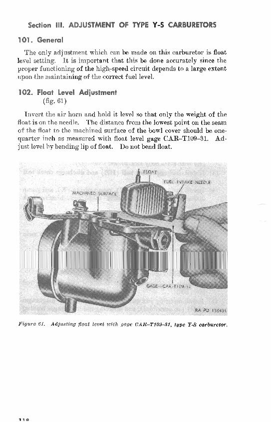
102. Float Level Adjustment (fig. 61)
Invert the air horn and hold i t level so that only the weight of the float is on the needle. The distance from the lowest point on the seam of the float to the machined surface of the bowl cover should be one- quarter inch as measured with float level gage CAR-T109-31. Ad- just level hy bending lip of float. Do not bend float.
Figure 61. Adjusting float level; with gage CAR-T10941, type Y-R owburetor.