lv split systems water source heat pump - bosch … · 3 | lv split systems | commercial geothermal...
TRANSCRIPT

boschheatingandcooling.com | 1
SubSubSubSubjejejececcccccccccccccecceeccccccceccccececcccccccccccccccccccccccct ttttto o o co co hanhanana gegegegege ege gegeege wwiwiwiwiwitwitwitwwitwitwitwitwitwitwitwitwitwitwiitwitwitwitwitwwittitwittwitwitwitwitwitwitwiwiwittitwitwwittwitttwitwittitwitwitittwitwitwitwittwitwitwiiwiwitwitwitiwitititwitititwitititttwiittww tttttttww tttttttttw ttttttthouhouhhhhohohohhohhohohhoohohohohouhouhouhouhouhouhhouhouhouhouhhhhhhohohohohouhouhouhouhouhhohohohohohououhouhouhouhhhouhouhouhououhouhouhouhohoouhouhouhouhououhouhhhhoohoouhouhouhhhhhhhhouuhhhhhoooououhhoooouhhhhooooooohhoooohouhoohououhouuououohohouuouuhhhouououhhh uh ttttt t t ppppttttttttt ptttttt ttttttttt t t tttttttttttttttttt rioirioriorioioooior nr nr nr notiotiotice.ce.
boschhhhhhheeateatttttttingingingingingingingggandandandandandandandandandandnnnn coocoocooccoocoocooccoolinlinlinliniiinliniiiiiii g.cg.cg.cg.cg.ccccg.cc.ccccomomomomommm | || | | || 1111
LV Split SystemsWater Source Heat Pump1½ to 6 ton
Commercial Sales Catalogboschheatingandcooling.com
The option-rich LV Split Systems offer lower operating costs, space-saving fl exibility and quiet comfort, making it a great choice for replacement and new construction projects
UP TO
15.9EER
UP TO
15 9UP TO
4.4COP
LVSplit Systems
1 | LV Split Systems | Commercial Geothermal Heat Pumps
Subject to change without prior notice.
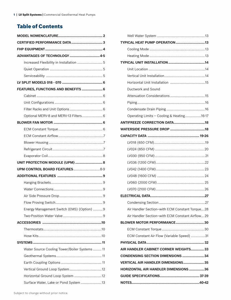
Table of Contents
MODEL NOMENCLATURE ............................................... 2
CERTIFIED PERFORMANCE DATA ................................. 3
FHP EQUIPMENT .............................................................4
ADVANTAGES OF TECHNOLOGY ................................4-5
Increased Flexibility in Installation ........................... 5
Quiet Operation ........................................................ 5
Serviceability ............................................................ 5
LV SPLIT MODELS 018 - 070 ...........................................6
FEATURES, FUNCTIONS AND BENEFITS ......................6
Cabinet ...................................................................... 6
Unit Confi gurations ................................................... 6
Filter Racks and Unit Options ................................... 6
Optional MERV-8 and MERV-13 Filters ...................... 6
BLOWER FAN MOTOR ....................................................6
ECM Constant Torque ............................................... 6
ECM Constant Airfl ow ................................................7
Blower Housing ..........................................................7
Refrigerant Circuit ......................................................7
Evaporator Coil ..........................................................8
UNIT PROTECTION MODULE (UPM) .............................8
UPM CONTROL BOARD FEATURES ............................8-9
ADDITIONAL FEATURES ................................................9
Hanging Brackets ....................................................... 9
Water Connections .................................................... 9
Air Side Pressure Drop .............................................. 9
Flow Proving Switch .................................................. 9
Energy Management Switch (EMS) (Option) .......... 9
Two-Position Water Valve .......................................... 9
ACCESSORIES ...............................................................10
Thermostats ..............................................................10
Hose Kits ...................................................................10
SYSTEMS ......................................................................... 11
Water Source Cooling Tower/Boiler Systems ......... 11
Geothermal Systems ................................................ 11
Earth Coupling Options ........................................... 11
Vertical Ground Loop System ..................................12
Horizontal Ground Loop System .............................12
Surface Water, Lake or Pond System ......................13
Well Water System ...................................................13
TYPICAL HEAT PUMP OPERATION ...............................13
Cooling Mode ...........................................................13
Heating Mode ...........................................................13
TYPICAL UNIT INSTALLATION .......................................14
Unit Location ............................................................14
Vertical Unit Installation ...........................................14
Horizontal Unit Installation .....................................15
Ductwork and Sound
Attenuation Considerations .....................................15
Piping ........................................................................16
Condensate Drain Piping .........................................16
Operating Limits – Cooling & Heating .................16-17
ANTIFREEZE CORRECTION DATA .................................18
WATERSIDE PRESSURE DROP .....................................18
CAPACITY DATA ....................................................... 19-26
LV018 (650 CFM) ......................................................19
LV024 (850 CFM) .................................................... 20
LV030 (950 CFM) .....................................................21
LV036 (1200 CFM) ....................................................22
LV042 (1400 CFM) ................................................... 23
LV048 (1600 CFM) .................................................. 24
LV060 (2000 CFM) .................................................. 25
LV070 (2100 CFM) ................................................... 26
ELECTRICAL DATA ..........................................................27
Condensing Section .................................................27
Air Handler Section–with ECM Constant Torque ... 28
Air Handler Section–with ECM Constant Airfl ow... 29
BLOWER MOTOR PERFORMANCE ..............................30
ECM Constant Torque .............................................30
ECM Constant Air Flow (Variable Speed) ...............31
PHYSICAL DATA ............................................................. 32
AIR HANDLER CABINET CORNER WEIGHTS ..............33
CONDENSING SECTION DIMENSIONS .......................34
VERTICAL AIR HANDLER DIMENSIONS ......................35
HORIZONTAL AIR HANDLER DIMENSIONS ................36
GUIDE SPECIFICATIONS .......................................... 37-39
NOTES........................................................................40-42
boschheatingandcooling.com | 2
Subject to change without prior notice.
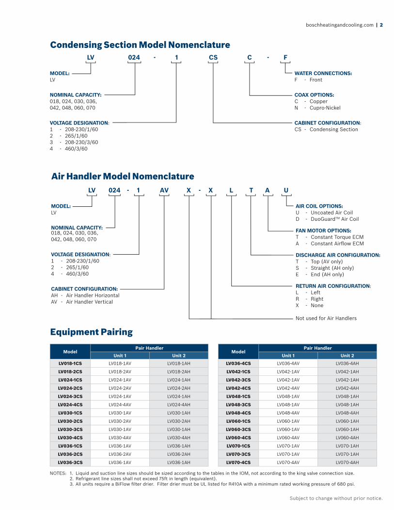
Condensing Section Model Nomenclature
Air Handler Model Nomenclature
MODEL:LV
NOMINAL CAPACITY:018, 024, 030, 036, 042, 048, 060, 070
VOLTAGE DESIGNATION:1 - 208-230/1/602 - 265/1/603 - 208-230/3/604 - 460/3/60
LV 024 - 1 CS C - F
WATER CONNECTIONS:F - Front
COAX OPTIONS:C - CopperN - Cupro-Nickel
CABINET CONFIGURATION:CS - Condensing Section
MODEL:LV
NOMINAL CAPACITY:018, 024, 030, 036, 042, 048, 060, 070
VOLTAGE DESIGNATION:1 - 208-230/1/602 - 265/1/604 - 460/3/60
CABINET CONFIGURATION:AH - Air Handler HorizontalAV - Air Handler Vertical
LV 024 - 1 AV X - X L T A U
AIR COIL OPTIONS:U - Uncoated Air CoilD - DuoGuardTM Air Coil
FAN MOTOR OPTIONS:T - Constant Torque ECMA - Constant Airfl ow ECM
DISCHARGE AIR CONFIGURATION:T - Top (AV only)S - Straight (AH only)E - End (AH only)
RETURN AIR CONFIGURATION:L - LeftR - RightX - None
Not used for Air Handlers
Equipment Pairing
ModelPair Handler
ModelPair Handler
Unit 1 Unit 2 Unit 1 Unit 2
LV018-1CS LV018-1AV LV018-1AH LV036-4CS LV036-4AV LV036-4AH
LV018-2CS LV018-2AV LV018-2AH LV042-1CS LV042-1AV LV042-1AH
LV024-1CS LV024-1AV LV024-1AH LV042-3CS LV042-1AV LV042-1AH
LV024-2CS LV024-2AV LV024-2AH LV042-4CS LV042-4AV LV042-4AH
LV024-3CS LV024-1AV LV024-1AH LV048-1CS LV048-1AV LV048-1AH
LV024-4CS LV024-4AV LV024-4AH LV048-3CS LV048-1AV LV048-1AH
LV030-1CS LV030-1AV LV030-1AH LV048-4CS LV048-4AV LV048-4AH
LV030-2CS LV030-2AV LV030-2AH LV060-1CS LV060-1AV LV060-1AH
LV030-3CS LV030-1AV LV030-1AH LV060-3CS LV060-1AV LV060-1AH
LV030-4CS LV030-4AV LV030-4AH LV060-4CS LV060-4AV LV060-4AH
LV036-1CS LV036-1AV LV036-1AH LV070-1CS LV070-1AV LV070-1AH
LV036-2CS LV036-2AV LV036-2AH LV070-3CS LV070-1AV LV070-1AH
LV036-3CS LV036-1AV LV036-1AH LV070-4CS LV070-4AV LV070-4AH
NOTES: 1. Liquid and suction line sizes should be sized according to the tables in the IOM, not according to the king valve connection size. 2. Refrigerant line sizes shall not exceed 75ft in length (equivalent). 3. All units require a BiFlow fi lter drier. Filter drier must be UL listed for R410A with a minimum rated working pressure of 680 psi.
3 | LV Split Systems | Commercial Geothermal Heat Pumps
Subject to change without prior notice.
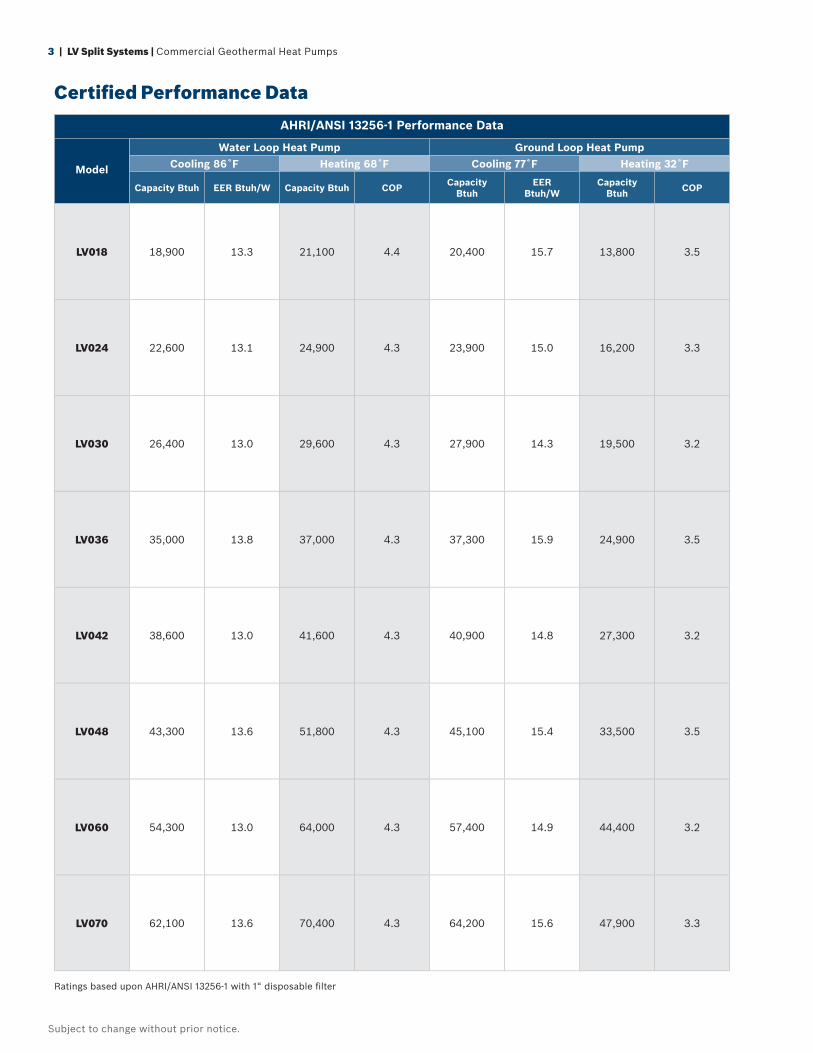
AHRI/ANSI 13256-1 Performance Data
Model
Water Loop Heat Pump Ground Loop Heat PumpCooling 86˚F Heating 68˚F Cooling 77˚F Heating 32˚F
Capacity Btuh EER Btuh/W Capacity Btuh COP Capacity Btuh
EER Btuh/W
Capacity Btuh COP
LV018 18,900 13.3 21,100 4.4 20,400 15.7 13,800 3.5
LV024 22,600 13.1 24,900 4.3 23,900 15.0 16,200 3.3
LV030 26,400 13.0 29,600 4.3 27,900 14.3 19,500 3.2
LV036 35,000 13.8 37,000 4.3 37,300 15.9 24,900 3.5
LV042 38,600 13.0 41,600 4.3 40,900 14.8 27,300 3.2
LV048 43,300 13.6 51,800 4.3 45,100 15.4 33,500 3.5
LV060 54,300 13.0 64,000 4.3 57,400 14.9 44,400 3.2
LV070 62,100 13.6 70,400 4.3 64,200 15.6 47,900 3.3
Ratings based upon AHRI/ANSI 13256-1 with 1“ disposable fi lter
Certifi ed Performance Data
boschheatingandcooling.com | 4
Subject to change without prior notice.
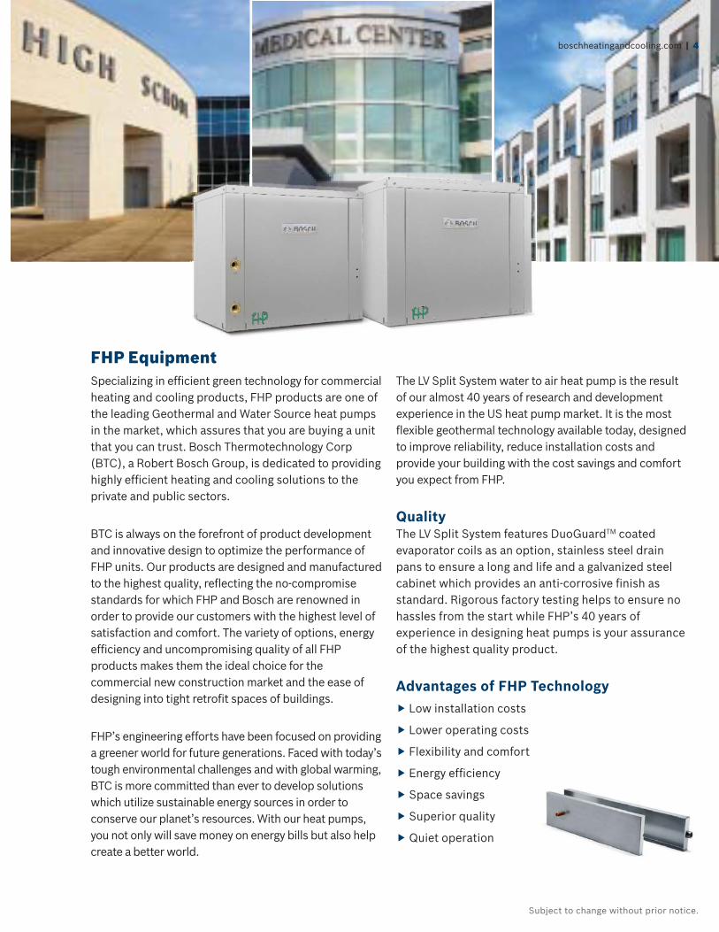
FHP EquipmentSpecializing in effi cient green technology for commercial heating and cooling products, FHP products are one of the leading Geothermal and Water Source heat pumps in the market, which assures that you are buying a unit that you can trust. Bosch Thermotechnology Corp (BTC), a Robert Bosch Group, is dedicated to providing highly effi cient heating and cooling solutions to the private and public sectors.
BTC is always on the forefront of product development and innovative design to optimize the performance of FHP units. Our products are designed and manufactured to the highest quality, refl ecting the no-compromise standards for which FHP and Bosch are renowned in order to provide our customers with the highest level of satisfaction and comfort. The variety of options, energy effi ciency and uncompromising quality of all FHP products makes them the ideal choice for the commercial new construction market and the ease of designing into tight retrofi t spaces of buildings.
FHP’s engineering efforts have been focused on providing a greener world for future generations. Faced with today’s tough environmental challenges and with global warming, BTC is more committed than ever to develop solutions which utilize sustainable energy sources in order to conserve our planet’s resources. With our heat pumps, you not only will save money on energy bills but also help create a better world.
The LV Split System water to air heat pump is the result of our almost 40 years of research and development experience in the US heat pump market. It is the most fl exible geothermal technology available today, designed to improve reliability, reduce installation costs and provide your building with the cost savings and comfort you expect from FHP.
QualityThe LV Split System features DuoGuardTM coated evaporator coils as an option, stainless steel drain pans to ensure a long and life and a galvanized steel cabinet which provides an anti-corrosive fi nish as standard. Rigorous factory testing helps to ensure no hassles from the start while FHP’s 40 years of experience in designing heat pumps is your assurance of the highest quality product.
Advantages of FHP Technology Low installation costs
Lower operating costs
Flexibility and comfort
Energy effi ciency
Space savings
Superior quality
Quiet operation
5 | LV Split Systems | Commercial Geothermal Heat Pumps
Subject to change without prior notice.
Increased Flexibility in InstallationThe LV Split condensing section can be placed remotely from the air handler section which allows for the unit installation to be in locations where space is limited. Additionally, this orientation allows installing the condensing section, which is the major contribu-tor to noise and vibration, to be away from occupied areas. Multiple condensing units may be centrally located to facilitate servicing.
The location of the LV Split air handlers can be concealed within a variety of areas inside the building where it will connect to air and ventilation ducts to deliver comfort-able air. Air handling sections are available in vertical or horizontal confi gurations from 1.5 through 6 tons so there is a unit to meet your every need.
Quiet Operation The ECM (Electronically Commutated Motor) motors on this unit are extremely quiet. The air fl ow can be adjusted to suit a specifi c installation and ensure your highest level of comfort.
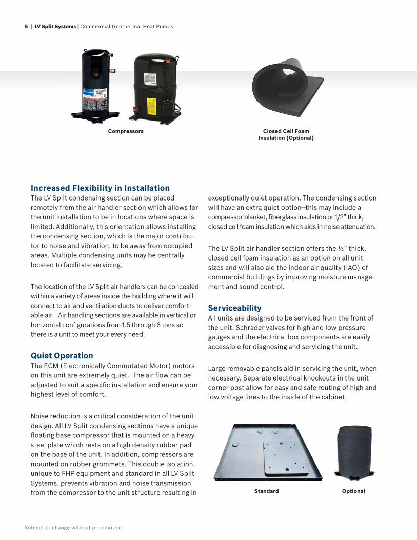
Noise reduction is a critical consideration of the unit design. All LV Split condensing sections have a unique fl oating base compressor that is mounted on a heavy steel plate which rests on a high density rubber pad on the base of the unit. In addition, compressors are mounted on rubber grommets. This double isolation, unique to FHP equipment and standard in all LV Split Systems, prevents vibration and noise transmission from the compressor to the unit structure resulting in
exceptionally quiet operation. The condensing section will have an extra quiet option—this may include a compressor blanket, fi berglass insulation or 1/2” thick, closed cell foam insulation which aids in noise attenuation.
The LV Split air handler section offers the ½” thick, closed cell foam insulation as an option on all unit sizes and will also aid the indoor air quality (IAQ) of commercial buildings by improving moisture manage-ment and sound control.
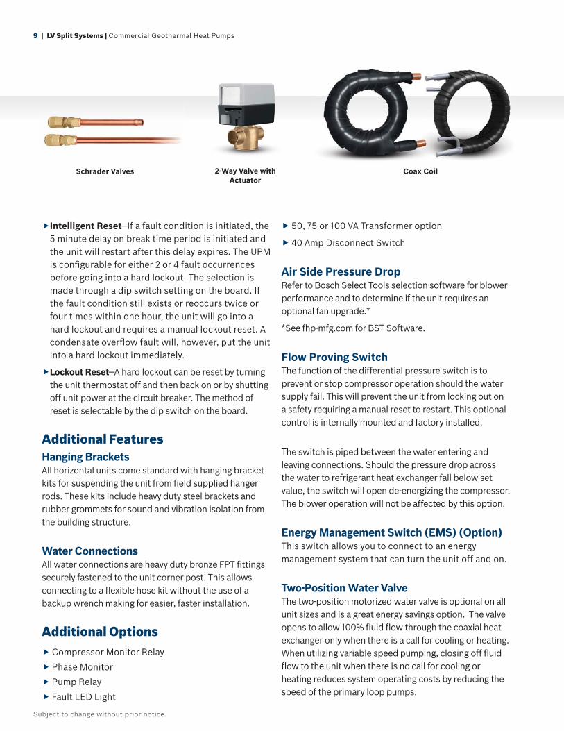
Serviceability All units are designed to be serviced from the front of the unit. Schrader valves for high and low pressure gauges and the electrical box components are easily accessible for diagnosing and servicing the unit.
Large removable panels aid in servicing the unit, when necessary. Separate electrical knockouts in the unit corner post allow for easy and safe routing of high and low voltage lines to the inside of the cabinet.
OptionalStandard
Closed Cell Foam Insulation (Optional)
Compressors
Subject to change without prior notice.
boschheatingandcooling.com | 6
LV Split System Models 018 - 070The LV Split System is a cost-effective, single stage water source heat pump designed for commercial retrofi t and new construction applications.
8 split systems from 1½ through 6 tons
Features, Functions and BenefitsCabinet The LV cabinetry is constructed using heavy-gauge, galvanized steel. This type of steel provides superior corrosion protection for units installed indoors.
All interior surfaces are lined with ½" thick, 1.5 lb./cu.ft. density micromat multi-density, coated fi berglass insula-tion for thermal insulation and acoustical attenuation. This insulation is non-combustible, non-hydroscopic and does not support fungal growth. Insulation meets NFPA 90A and 90B for fi re protection, UL 181 erosion require-ments, and is certifi ed to meet the GREENGUARD Indoor Air Quality Standard for Low Emitting Products.
Protection against corrosion is a feature in the LV Split System. The stainless steel drain pan will last the lifetime of the unit while helping to resist corrosion and will avoid cracking that may occur with steel or plastic materials.
Unit Confi gurationsAll air handler sections are available in horizontal and vertical confi gurations. Additionally, several options of return air and supply air are offered as standard, providing confi guration fl exibility.
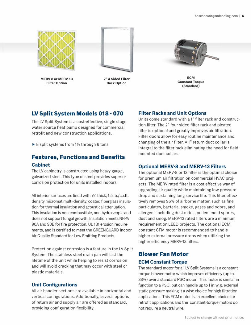
Filter Racks and Unit OptionsUnits come standard with a 1” fi lter rack and construc-tion fi lter. The 2” four-sided fi lter rack and pleated fi lter is optional and greatly improves air fi ltration. Filter doors allow for easy routine maintenance and changing of the air fi lter. A 1” return duct collar is integral to the fi lter rack eliminating the need for fi eld mounted duct collars.
Optional MERV-8 and MERV-13 FiltersThe optional MERV-8 or 13 fi lter is the optimal choice for premium air fi ltration on commercial HVAC proj-ects. The MERV rated fi lter is a cost effective way of upgrading air quality while maintaining low pressure drop and sustaining long service life. This fi lter effec-tively removes 96% of airborne matter, such as fi ne particulates, bacteria, smoke, gases and odors, and allergens including dust mites, pollen, mold spores, dust and smog. MERV-13 rated fi lters are a minimum requirement on LEED projects. The optional ECM constant CFM motor is recommended to handle higher external pressure drops when utilizing the higher effi ciency MERV-13 fi lters.
Blower Fan MotorECM Constant Torque The standard motor for all LV Split Systems is a constant torque blower motor which improves effi ciency (up to 33%) over a standard PSC motor. This motor is similar in function to a PSC, but can handle up to 1 in.w.g. external static pressure making it a wise choice for high fi ltration applications. This ECM motor is an excellent choice for retrofi t applications and the constant-torque motors do not require a neutral wire.
MERV-8 or MERV-13 Filter Option
2” 4-Sided FilterRack Option
ECM Constant Torque
(Standard)
7 | LV Split Systems | Commercial Geothermal Heat Pumps
Subject to change without prior notice.
ECM Constant Airfl ow
Option
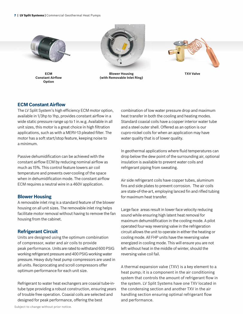
ECM Constant Airfl owThe LV Split System’s high effi ciency ECM motor option, available in 1/3hp to 1hp, provides constant airfl ow in a wide static pressure range up to 1 in.w.g. Available in all unit sizes, this motor is a great choice in high fi ltration applications, such as with a MERV-13 pleated fi lter. The motor has a soft start/stop feature, keeping noise to a minimum.
Passive dehumidifi cation can be achieved with the constant airfl ow ECM by reducing nominal airfl ow as much as 15%. This control feature lowers air coil temperature and prevents over-cooling of the space when in dehumidifi cation mode. The constant airfl ow ECM requires a neutral wire in a 460V application.
Blower HousingA removable inlet ring is a standard feature of the blower housing on all unit sizes. The removable inlet ring helps facilitate motor removal without having to remove the fan housing from the cabinet.
Refrigerant CircuitUnits are designed using the optimum combination of compressor, water and air coils to provide peak performance. Units are rated to withstand 600 PSIG working refrigerant pressure and 400 PSIG working water pressure. Heavy duty heat pump compressors are used in all units. Reciprocating and scroll compressors offer optimum performance for each unit size.
Refrigerant to water heat exchangers are coaxial tube-in-tube type providing a robust construction, ensuring years of trouble free operation. Coaxial coils are selected and designed for peak performance, offering the best
combination of low water pressure drop and maximum heat transfer in both the cooling and heating modes. Standard coaxial coils have a copper interior water tube and a steel outer shell. Offered as an option is our cupro-nickel coils for when an application may have water quality that is of lower quality.
In geothermal applications where fl uid temperatures can drop below the dew point of the surrounding air, optional insulation is available to prevent water coils and refrigerant piping from sweating.
Air side refrigerant coils have copper tubes, aluminum fi ns and side plates to prevent corrosion. The air coils are state-of-the-art, employing lanced fi n and rifl ed tubing for maximum heat transfer.
Large face areas result in lower face velocity reducing sound while ensuring high latent heat removal for maximum dehumidifi cation in the cooling mode. A pilot operated four-way reversing valve in the refrigeration circuit allows the unit to operate in either the heating or cooling mode. All FHP units have the reversing valve energized in cooling mode. This will ensure you are not left without heat in the middle of winter, should the reversing valve coil fail.
A thermal expansion valve (TXV) is a key element to a heat pump; it is a component in the air conditioning system that controls the amount of refrigerant fl ow in the system. LV Split Systems have one TXV located in the condensing section and another TXV in the air handling section ensuring optimal refrigerant fl ow and performance.
TXV ValveBlower Housing (with Removable Inlet Ring)
boschheatingandcooling.com | 8
Subject to change without prior notice.
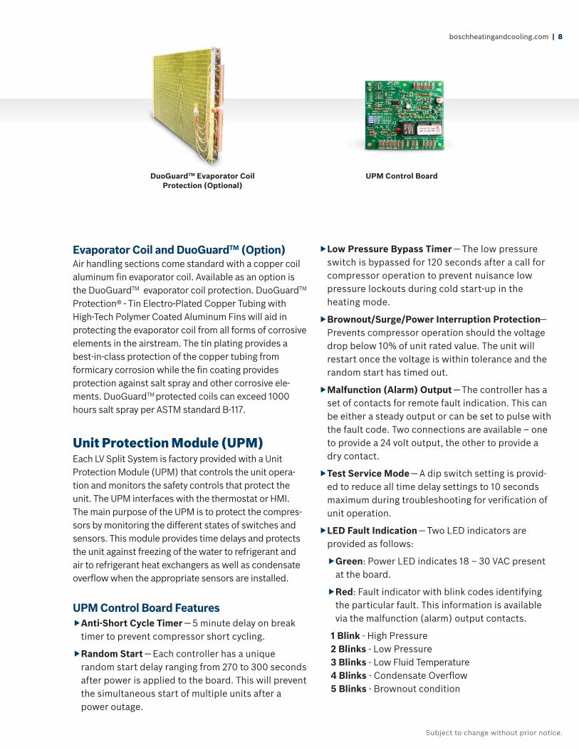
UPM Control Board
Evaporator Coil and DuoGuardTM (Option)Air handling sections come standard with a copper coil aluminum fi n evaporator coil. Available as an option is the DuoGuardTM evaporator coil protection. DuoGuardTM Protection® - Tin Electro-Plated Copper Tubing with High-Tech Polymer Coated Aluminum Fins will aid in protecting the evaporator coil from all forms of corrosive elements in the airstream. The tin plating provides a best-in-class protection of the copper tubing from formicary corrosion while the fi n coating provides protection against salt spray and other corrosive ele-ments. DuoGuardTM protected coils can exceed 1000 hours salt spray per ASTM standard B-117.
Unit Protection Module (UPM)Each LV Split System is factory provided with a Unit Protection Module (UPM) that controls the unit opera-tion and monitors the safety controls that protect the unit. The UPM interfaces with the thermostat or HMI. The main purpose of the UPM is to protect the compres-sors by monitoring the different states of switches and sensors. This module provides time delays and protects the unit against freezing of the water to refrigerant and air to refrigerant heat exchangers as well as condensate overfl ow when the appropriate sensors are installed.
UPM Control Board Features Anti-Short Cycle Timer — 5 minute delay on break
timer to prevent compressor short cycling.
Random Start — Each controller has a unique random start delay ranging from 270 to 300 seconds after power is applied to the board. This will prevent the simultaneous start of multiple units after a power outage.
Low Pressure Bypass Timer — The low pressure switch is bypassed for 120 seconds after a call for compressor operation to prevent nuisance low pressure lockouts during cold start-up in the heating mode.
Brownout/Surge/Power Interruption Protection— Prevents compressor operation should the voltage drop below 10% of unit rated value. The unit will restart once the voltage is within tolerance and the random start has timed out.
Malfunction (Alarm) Output — The controller has a set of contacts for remote fault indication. This can be either a steady output or can be set to pulse with the fault code. Two connections are available – one to provide a 24 volt output, the other to provide a dry contact.
Test Service Mode — A dip switch setting is provid-ed to reduce all time delay settings to 10 seconds maximum during troubleshooting for verifi cation of unit operation.
LED Fault Indication — Two LED indicators are provided as follows:
Green: Power LED indicates 18 – 30 VAC present at the board.
Red: Fault indicator with blink codes identifying the particular fault. This information is available via the malfunction (alarm) output contacts.
1 Blink - High Pressure2 Blinks - Low Pressure3 Blinks - Low Fluid Temperature4 Blinks - Condensate Overfl ow5 Blinks - Brownout condition
DuoGuardTM Evaporator Coil Protection (Optional)
9 | LV Split Systems | Commercial Geothermal Heat Pumps
Subject to change without prior notice.
Intelligent Reset—If a fault condition is initiated, the 5 minute delay on break time period is initiated and the unit will restart after this delay expires. The UPM is confi gurable for either 2 or 4 fault occurrences before going into a hard lockout. The selection is made through a dip switch setting on the board. If the fault condition still exists or reoccurs twice or four times within one hour, the unit will go into a hard lockout and requires a manual lockout reset. A condensate overfl ow fault will, however, put the unit into a hard lockout immediately.
Lockout Reset—A hard lockout can be reset by turning the unit thermostat off and then back on or by shutting off unit power at the circuit breaker. The method of reset is selectable by the dip switch on the board.
Additional Features Hanging BracketsAll horizontal units come standard with hanging bracket kits for suspending the unit from fi eld supplied hanger rods. These kits include heavy duty steel brackets and rubber grommets for sound and vibration isolation from the building structure.
Water ConnectionsAll water connections are heavy duty bronze FPT fi ttings securely fastened to the unit corner post. This allows connecting to a fl exible hose kit without the use of a backup wrench making for easier, faster installation.
Additional Options Compressor Monitor Relay
Phase Monitor
Pump Relay
Fault LED Light
50, 75 or 100 VA Transformer option
40 Amp Disconnect Switch
Air Side Pressure DropRefer to Bosch Select Tools selection software for blower performance and to determine if the unit requires an optional fan upgrade.*
*See fhp-mfg.com for BST Software.
Flow Proving Switch The function of the differential pressure switch is to prevent or stop compressor operation should the water supply fail. This will prevent the unit from locking out on a safety requiring a manual reset to restart. This optional control is internally mounted and factory installed.
The switch is piped between the water entering and leaving connections. Should the pressure drop across the water to refrigerant heat exchanger fall below set value, the switch will open de-energizing the compressor. The blower operation will not be affected by this option.
Energy Management Switch (EMS) (Option)This switch allows you to connect to an energy management system that can turn the unit off and on.
Two-Position Water ValveThe two-position motorized water valve is optional on all unit sizes and is a great energy savings option. The valve opens to allow 100% fl uid fl ow through the coaxial heat exchanger only when there is a call for cooling or heating. When utilizing variable speed pumping, closing off fl uid fl ow to the unit when there is no call for cooling or heating reduces system operating costs by reducing the speed of the primary loop pumps.
2-Way Valve with Actuator
Schrader Valves Coax Coil
boschheatingandcooling.com | 10
Subject to change without prior notice.
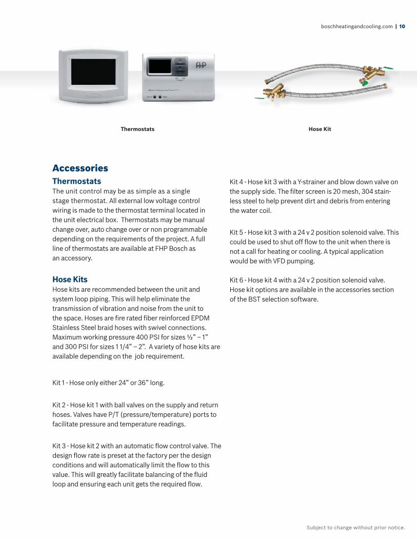
AccessoriesThermostatsThe unit control may be as simple as a single stage thermostat. All external low voltage control wiring is made to the thermostat terminal located in the unit electrical box. Thermostats may be manual change over, auto change over or non programmable depending on the requirements of the project. A full line of thermostats are available at FHP Bosch as an accessory.
Hose KitsHose kits are recommended between the unit and system loop piping. This will help eliminate the transmission of vibration and noise from the unit to the space. Hoses are fi re rated fi ber reinforced EPDM Stainless Steel braid hoses with swivel connections.Maximum working pressure 400 PSI for sizes ½” – 1” and 300 PSI for sizes 1 1/4” – 2”. A variety of hose kits are available depending on the job requirement.
Kit 1 - Hose only either 24” or 36” long.
Kit 2 - Hose kit 1 with ball valves on the supply and return hoses. Valves have P/T (pressure/temperature) ports to facilitate pressure and temperature readings.
Kit 3 - Hose kit 2 with an automatic fl ow control valve. The design fl ow rate is preset at the factory per the design conditions and will automatically limit the fl ow to this value. This will greatly facilitate balancing of the fl uid loop and ensuring each unit gets the required fl ow.
Kit 4 - Hose kit 3 with a Y-strainer and blow down valve on the supply side. The fi lter screen is 20 mesh, 304 stain-less steel to help prevent dirt and debris from entering the water coil.
Kit 5 - Hose kit 3 with a 24 v 2 position solenoid valve. This could be used to shut off fl ow to the unit when there is not a call for heating or cooling. A typical application would be with VFD pumping.
Kit 6 - Hose kit 4 with a 24 v 2 position solenoid valve. Hose kit options are available in the accessories section of the BST selection software.
Thermostats Hose Kit
11 | LV Split Systems | Commercial Geothermal Heat Pumps
Subject to change without prior notice.
LV Split Systems may be used in a variety of different applications depending on the system design. An overview of tower/boiler and geothermal systems is given below. There could be several variations and combinations of these systems.
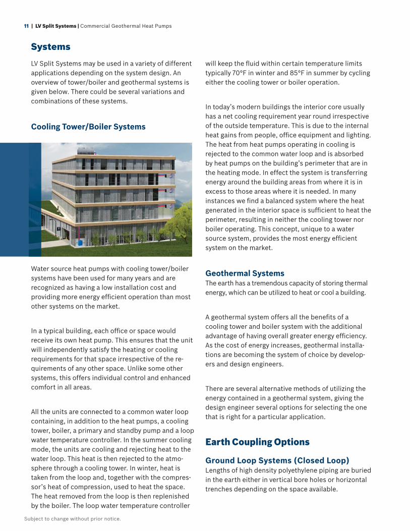
Cooling Tower/Boiler Systems
Water source heat pumps with cooling tower/boiler systems have been used for many years and are recognized as having a low installation cost and providing more energy effi cient operation than most other systems on the market.
In a typical building, each offi ce or space would receive its own heat pump. This ensures that the unit will independently satisfy the heating or cooling requirements for that space irrespective of the re-quirements of any other space. Unlike some other systems, this offers individual control and enhanced comfort in all areas.
All the units are connected to a common water loop containing, in addition to the heat pumps, a cooling tower, boiler, a primary and standby pump and a loop water temperature controller. In the summer cooling mode, the units are cooling and rejecting heat to the water loop. This heat is then rejected to the atmo-sphere through a cooling tower. In winter, heat is taken from the loop and, together with the compres-sor’s heat of compression, used to heat the space. The heat removed from the loop is then replenished by the boiler. The loop water temperature controller
will keep the fl uid within certain temperature limits typically 70°F in winter and 85°F in summer by cycling either the cooling tower or boiler operation.
In today’s modern buildings the interior core usually has a net cooling requirement year round irrespective of the outside temperature. This is due to the internal heat gains from people, offi ce equipment and lighting. The heat from heat pumps operating in cooling is rejected to the common water loop and is absorbed by heat pumps on the building’s perimeter that are in the heating mode. In effect the system is transferring energy around the building areas from where it is in excess to those areas where it is needed. In many instances we fi nd a balanced system where the heat generated in the interior space is suffi cient to heat the perimeter, resulting in neither the cooling tower nor boiler operating. This concept, unique to a water source system, provides the most energy effi cient system on the market.
Geothermal SystemsThe earth has a tremendous capacity of storing thermal energy, which can be utilized to heat or cool a building.
A geothermal system offers all the benefi ts of a cooling tower and boiler system with the additional advantage of having overall greater energy effi ciency. As the cost of energy increases, geothermal installa-tions are becoming the system of choice by develop-ers and design engineers.
There are several alternative methods of utilizing the energy contained in a geothermal system, giving the design engineer several options for selecting the one that is right for a particular application.
Earth Coupling Options
Ground Loop Systems (Closed Loop)Lengths of high density polyethylene piping are buried in the earth either in vertical bore holes or horizontal trenches depending on the space available.
Systems
boschheatingandcooling.com | 12
Subject to change without prior notice.
Fluid from the loop inside the building circulates through these pipes either rejecting heat to the ground when there is a net cooling requirement or absorbing heat from the ground when heating is the dominant requirement.
The temperature of the earth below 6 feet is relatively constant and is not affected by the ambient tempera-ture. For this reason, the ground temperature is cooler than the summer ambient and warmer than the winter ambient in most regions. Geothermal systems are able to operate effectively in extreme ambient conditions exceeding 100°F in summer and -30°F in winter. This is one of the reasons why geothermal systems have such an advantage over other systems. An additional advantage is that no fossil fuels are used, reducing the carbon emission of the building.
Even in areas which are cooling or heating dominant a hybrid system can be used with a downsized cooling tower or boiler. This system will reduce the installed cost signifi cantly with only a modest impact on overall operating effi ciency.
Geothermal systems may cost more to install but the savings in energy and low maintenance costs more than off set this with payback times typically fi ve years or even less.
Vertical Ground Loop System
This method is used mainly in commercial buildings or where space for a loop fi eld is limited. Vertical holes 100 to 400 feet deep are drilled in the ground, and a single loop of high density polyethylene pipe with a U-tube at the bottom is installed. The bore hole is then sealed with grout to ensure good contact for heat transfer with the soil. The size of the project will determine how many bore holes are required. The vertical ground loops are then connected to a horizon-tal header pipe that carries fl uid to the building and circulated to each heat pump. The Earth’s tempera-ture is stable below the surface which is an advantage for this system and provides for the greater effi ciency. Vertical ground loop fi elds may be located under buildings or parking lots. The life expectancy is in excess of 50 years.
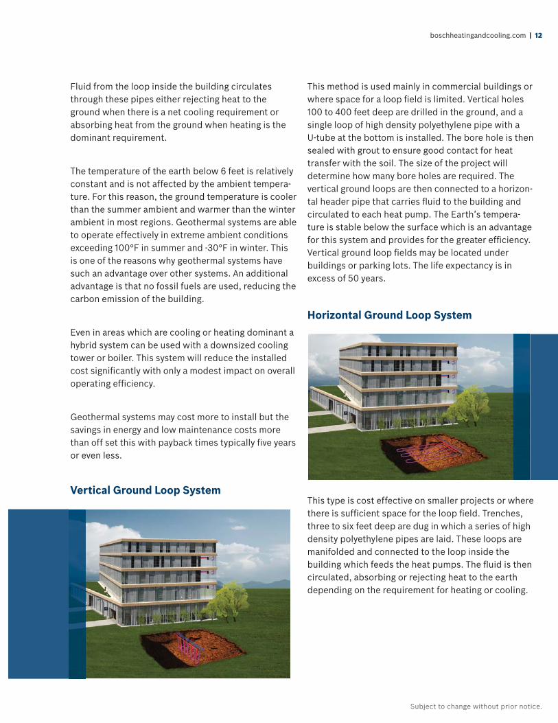
Horizontal Ground Loop System
This type is cost effective on smaller projects or where there is suffi cient space for the loop fi eld. Trenches, three to six feet deep are dug in which a series of high density polyethylene pipes are laid. These loops are manifolded and connected to the loop inside the building which feeds the heat pumps. The fl uid is then circulated, absorbing or rejecting heat to the earth depending on the requirement for heating or cooling.
13 | LV Split Systems | Commercial Geothermal Heat Pumps
Subject to change without prior notice.
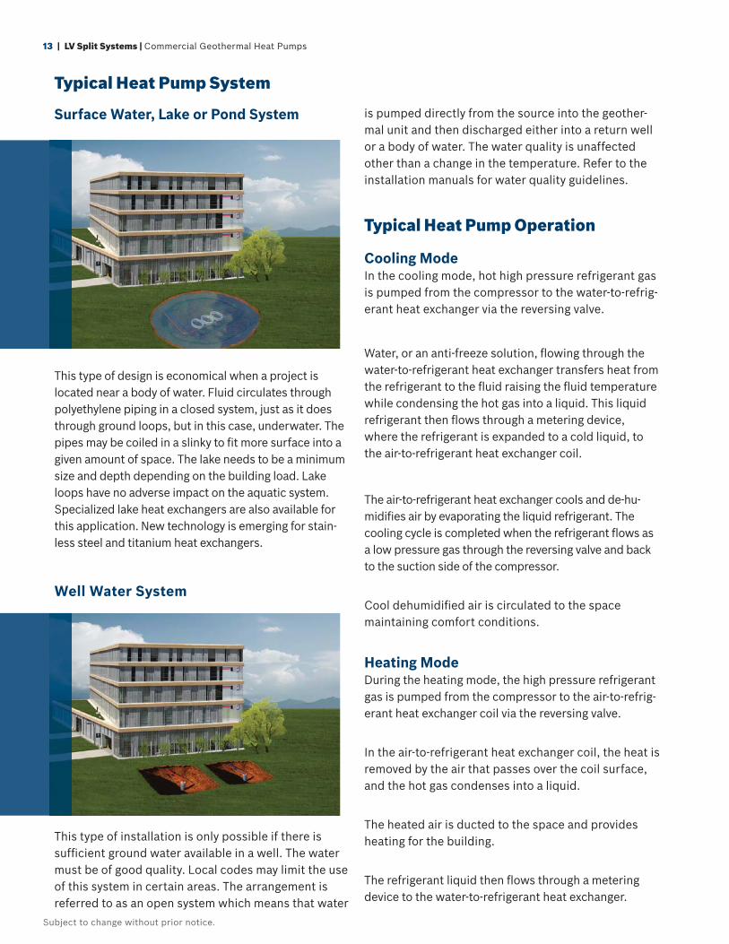
Surface Water, Lake or Pond System
This type of design is economical when a project is located near a body of water. Fluid circulates through polyethylene piping in a closed system, just as it does through ground loops, but in this case, underwater. The pipes may be coiled in a slinky to fi t more surface into a given amount of space. The lake needs to be a minimum size and depth depending on the building load. Lake loops have no adverse impact on the aquatic system. Specialized lake heat exchangers are also available for this application. New technology is emerging for stain-less steel and titanium heat exchangers.
Well Water System
This type of installation is only possible if there is suffi cient ground water available in a well. The water must be of good quality. Local codes may limit the use of this system in certain areas. The arrangement is referred to as an open system which means that water
is pumped directly from the source into the geother-mal unit and then discharged either into a return well or a body of water. The water quality is unaffected other than a change in the temperature. Refer to the installation manuals for water quality guidelines.
Typical Heat Pump Operation
Cooling ModeIn the cooling mode, hot high pressure refrigerant gas is pumped from the compressor to the water-to-refrig-erant heat exchanger via the reversing valve.
Water, or an anti-freeze solution, fl owing through the water-to-refrigerant heat exchanger transfers heat from the refrigerant to the fl uid raising the fl uid temperature while condensing the hot gas into a liquid. This liquid refrigerant then fl ows through a metering device, where the refrigerant is expanded to a cold liquid, to the air-to-refrigerant heat exchanger coil.
The air-to-refrigerant heat exchanger cools and de-hu-midifi es air by evaporating the liquid refrigerant. The cooling cycle is completed when the refrigerant fl ows as a low pressure gas through the reversing valve and back to the suction side of the compressor.
Cool dehumidifi ed air is circulated to the space maintaining comfort conditions.
Heating ModeDuring the heating mode, the high pressure refrigerant gas is pumped from the compressor to the air-to-refrig-erant heat exchanger coil via the reversing valve.
In the air-to-refrigerant heat exchanger coil, the heat is removed by the air that passes over the coil surface, and the hot gas condenses into a liquid.
The heated air is ducted to the space and provides heating for the building.
The refrigerant liquid then fl ows through a metering device to the water-to-refrigerant heat exchanger.
Typical Heat Pump System
boschheatingandcooling.com | 14
Subject to change without prior notice.
Water, or an anti-freeze solution, circulates through this heat exchanger and is cooled by the evaporating refrigerant which evaporates into a gas. The heating cycle is completed when the refrigerant fl ows as a low pressure gas through the reversing valve and back to the suction side of the compressor.
Unit LocationAny mechanical device will, at some point in time require servicing and repair.With this in mind suffi -cient space must be provided around the unit for service personnel to perform maintenance or repair.
Units are not designed for outdoor installation. Avoid locations where the unit may be exposed to freezing conditions or where the humidity levels could cause condensation on the unit panels, for example, when exposed to outdoor ambient conditions.
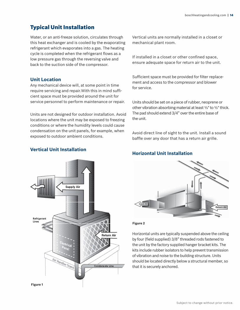
Vertical Unit Installation
Vertical units are normally installed in a closet or mechanical plant room.
If installed in a closet or other confi ned space, ensure adequate space for return air to the unit.
Suffi cient space must be provided for fi lter replace-ment and access to the compressor and blower for service.
Units should be set on a piece of rubber, neoprene or other vibration absorbing material at least ⅓" to ½" thick. The pad should extend 3/4” over the entire base of the unit.
Avoid direct line of sight to the unit. Install a sound baffl e over any door that has a return air grille.
Horizontal Unit Installation
Horizontal units are typically suspended above the ceiling by four (fi eld supplied) 3/8” threaded rods fastened to the unit by the factory supplied hanger bracket kits. The kits include rubber isolators to help prevent transmission of vibration and noise to the building structure. Units should be located directly below a structural member, so that it is securely anchored.
Typical Unit Installation
Figure 1
Figure 2
15 | LV Split Systems | Commercial Geothermal Heat Pumps
Subject to change without prior notice.
A horizontal unit should be positioned to allow for removal of the fi lters and access panels. Allow at least 18” clearance on each side of the unit for service and 36” in front of the unit for maintenance access. The fi lter needs to be slid out and suffi cient space must be provided to allow this.
Do not install the unit above any piping or electrical raceways. The unit should be able to be removed to the fl oor without major rearrangement of other mechanical or ceiling components.
Consideration needs to be made as to the location of the units. Avoid installing units directly above occu-pied spaces (e.g. above offi ce desks or classrooms). This will minimize possible disruption to the occu-pants if maintenance or service is required as well as keeping a potential source of noise out of the area. If possible, units should be installed above the hallway drop ceiling in schools, and the supply and return air is routed directly into classrooms. Local code may require fi re dampers to be used in this application.
Ductwork and Sound Attenuation Considerations
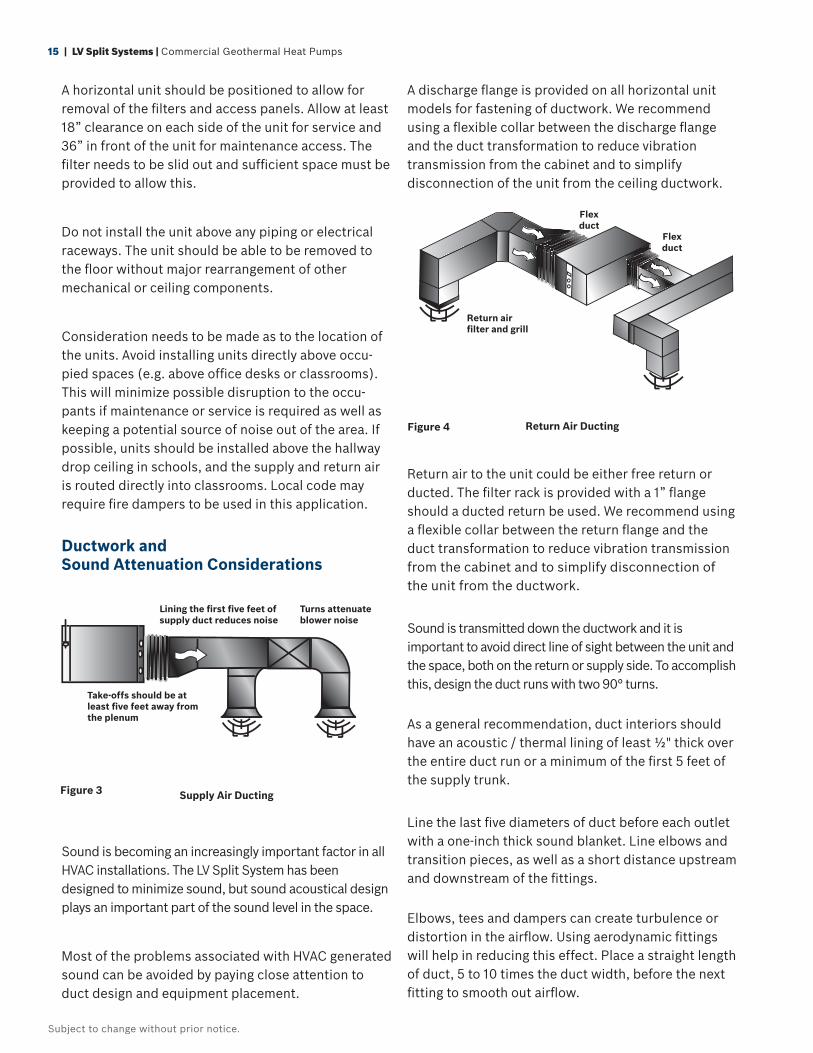
Supply Air Ducting
Sound is becoming an increasingly important factor in all HVAC installations. The LV Split System has been designed to minimize sound, but sound acoustical design plays an important part of the sound level in the space.
Most of the problems associated with HVAC generated sound can be avoided by paying close attention to duct design and equipment placement.
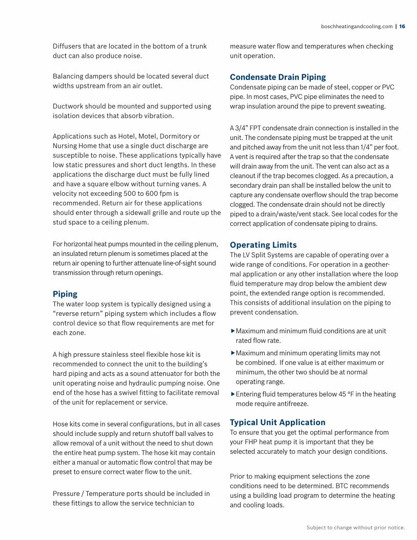
A discharge fl ange is provided on all horizontal unit models for fastening of ductwork. We recommend using a fl exible collar between the discharge fl ange and the duct transformation to reduce vibration transmission from the cabinet and to simplify disconnection of the unit from the ceiling ductwork.
Return Air Ducting
Return air to the unit could be either free return or ducted. The fi lter rack is provided with a 1” fl ange should a ducted return be used. We recommend using a fl exible collar between the return fl ange and the duct transformation to reduce vibration transmission from the cabinet and to simplify disconnection of the unit from the ductwork.
Sound is transmitted down the ductwork and it is important to avoid direct line of sight between the unit and the space, both on the return or supply side. To accomplish this, design the duct runs with two 90° turns.
As a general recommendation, duct interiors should have an acoustic / thermal lining of least ½" thick over the entire duct run or a minimum of the fi rst 5 feet of the supply trunk.
Line the last fi ve diameters of duct before each outlet with a one-inch thick sound blanket. Line elbows and transition pieces, as well as a short distance upstream and downstream of the fi ttings.
Elbows, tees and dampers can create turbulence or distortion in the airfl ow. Using aerodynamic fi ttings will help in reducing this effect. Place a straight length of duct, 5 to 10 times the duct width, before the next fi tting to smooth out airfl ow.
Lining the fi rst fi ve feet of supply duct reduces noise
Turns attenuate blower noise
Take-offs should be at least fi ve feet away from the plenum
Flex duct
Flex duct
Return airfi lter and grill
Figure 3
Figure 4
boschheatingandcooling.com | 16
Subject to change without prior notice.
Diffusers that are located in the bottom of a trunk duct can also produce noise.
Balancing dampers should be located several duct widths upstream from an air outlet.
Ductwork should be mounted and supported using isolation devices that absorb vibration.
Applications such as Hotel, Motel, Dormitory or Nursing Home that use a single duct discharge are susceptible to noise. These applications typically have low static pressures and short duct lengths. In these applications the discharge duct must be fully lined and have a square elbow without turning vanes. A velocity not exceeding 500 to 600 fpm is recommended. Return air for these applications should enter through a sidewall grille and route up the stud space to a ceiling plenum.
For horizontal heat pumps mounted in the ceiling plenum, an insulated return plenum is sometimes placed at the return air opening to further attenuate line-of-sight sound transmission through return openings.
PipingThe water loop system is typically designed using a “reverse return” piping system which includes a fl ow control device so that fl ow requirements are met for each zone.
A high pressure stainless steel fl exible hose kit is recommended to connect the unit to the building’s hard piping and acts as a sound attenuator for both the unit operating noise and hydraulic pumping noise. One end of the hose has a swivel fi tting to facilitate removal of the unit for replacement or service.
Hose kits come in several confi gurations, but in all cases should include supply and return shutoff ball valves to allow removal of a unit without the need to shut down the entire heat pump system. The hose kit may contain either a manual or automatic fl ow control that may be preset to ensure correct water fl ow to the unit.
Pressure / Temperature ports should be included in these fi ttings to allow the service technician to
measure water fl ow and temperatures when checking unit operation.
Condensate Drain PipingCondensate piping can be made of steel, copper or PVC pipe. In most cases, PVC pipe eliminates the need to wrap insulation around the pipe to prevent sweating.
A 3/4” FPT condensate drain connection is installed in the unit. The condensate piping must be trapped at the unit and pitched away from the unit not less than 1/4” per foot. A vent is required after the trap so that the condensate will drain away from the unit. The vent can also act as a cleanout if the trap becomes clogged. As a precaution, a secondary drain pan shall be installed below the unit to capture any condensate overfl ow should the trap become clogged. The condensate drain should not be directly piped to a drain/waste/vent stack. See local codes for the correct application of condensate piping to drains.
Operating LimitsThe LV Split Systems are capable of operating over a wide range of conditions. For operation in a geother-mal application or any other installation where the loop fl uid temperature may drop below the ambient dew point, the extended range option is recommended. This consists of additional insulation on the piping to prevent condensation.
Maximum and minimum fl uid conditions are at unit rated fl ow rate.
Maximum and minimum operating limits may not be combined. If one value is at either maximum or minimum, the other two should be at normal operating range.
Entering fl uid temperatures below 45 °F in the heating mode require antifreeze.
Typical Unit Application To ensure that you get the optimal performance from your FHP heat pump it is important that they be selected accurately to match your design conditions.
Prior to making equipment selections the zone conditions need to be determined. BTC recommends using a building load program to determine the heating and cooling loads.

17 | LV Split Systems | Commercial Geothermal Heat Pumps
Subject to change without prior notice.
The catalog provides a wide range of entering air and water conditions that will meet most applications. The unit performance can be determined by referring to the data tables from page 19 to 26.
Our Bosch Select Tools Selection Software (BST) is designed to provide you with a fast and accurate selection based on your specifi c conditions. This software is available through the commercial website. You may click on the BST link and request an account.
The following is a typical example for a unit selection. Design conditions are given as follows:
Total Cooling Load = 37.8 MBTUH
Sensible Cooling Load = 29.5 MBTUH
Total Heating Load = 41.4 MBTUH
Air Flow Required = 1140 CFM
Entering Air Temp Cooling (db/wb) = 75°F / 63°F
Entering Air Temp Heating = 60°F
Entering Water Temp Cooling = 80°F
Entering Water Temp Heating = 70°F
Fluid Flow Required = 9 GPM
The FHP Split System LV036 would not be suffi cient given these conditions as it provides a total cooling capacity of 35.9 MBTUH and a sensible capacity of 27.9 MBTUH.
The next size unit, the LV042 has a total cooling capacity of 38.9 MBTUH and a sensible capacity of 30.9 MBTUH. This meets the design conditions as closely as possible.
Please be aware that interpolation between ratings within a table is allowed, but extrapolation is a method of estimating new data by expanding outside a known range of data points and should not be considered accurate.
Operating Limits – Cooling & Heating Extended Range Option
Cooling
Minimum ambient air temperature °F 50
Maximum ambient air temperature °F 100
Minimum evaporator entering air db/wb °F 68/57
Rated air coil entering air db/wb °F 80/67
Maximum evaporator entering air db/wb °F 95/85
Minimum water coil entering fl uid temperature °F 40
Water loop typical coil entering fl uid range temperature °F 70/90
Maximum water coil entering fl uid temperature °F 110
Heating
Minimum ambient air temperature °F 40
Maximum ambient air temperature °F 85
Minimum evaporator entering air db °F 50
Rated air coil entering air °F 68
Maximum evaporator entering air db °F 80
Normal water coil entering fl uid range °F 25-80*
Minimum water coil entering Fluid °F 20*
* = antifreeze solution is required at these fl uid temperatures.
Unit Operating Limits —LV Split Systems
boschheatingandcooling.com | 18
Subject to change without prior notice.
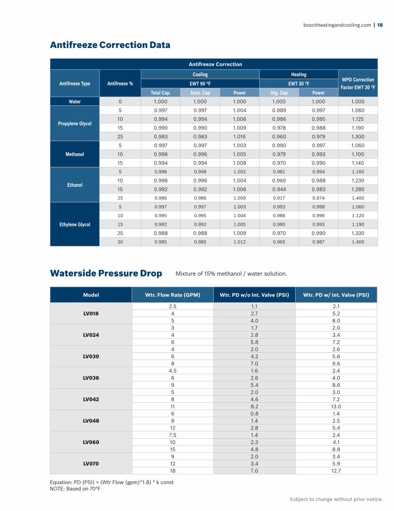
Antifreeze Correction
Antifreeze Type Antifreeze %
Cooling HeatingWPD Correction
Factor EWT 30 °FEWT 90 °F EWT 30 °F
Total Cap. Sens. Cap Power Htg. Cap Power
Water 0 1.000 1.000 1.000 1.000 1.000 1.000
Propylene Glycol
5 0.997 0.997 1.004 0.989 0.997 1.060
10 0.994 0.994 1.006 0.986 0.995 1.125
15 0.990 0.990 1.009 0.978 0.988 1.190
25 0.983 0.983 1.016 0.960 0.979 1.300
Methanol
5 0.997 0.997 1.003 0.990 0.997 1.060
10 0.996 0.996 1.005 0.979 0.993 1.100
15 0.994 0.994 1.008 0.970 0.990 1.140
Ethanol
5 0.998 0.998 1.002 0.981 0.994 1.160
10 0.996 0.996 1.004 0.960 0.988 1.230
15 0.992 0.992 1.006 0.944 0.983 1.280
25 0.986 0.986 1.009 0.917 0.974 1.400
Ethylene Glycol
5 0.997 0.997 1.003 0.993 0.998 1.060
10 0.995 0.995 1.004 0.986 0.996 1.120
15 0.992 0.992 1.005 0.980 0.993 1.190
25 0.988 0.988 1.009 0.970 0.990 1.330
30 0.985 0.985 1.012 0.965 0.987 1.400
Model Wtr. Flow Rate (GPM) Wtr. PD w/o Int. Valve (PSI) Wtr. PD w/ Int. Valve (PSI)
LV0182.5 1.1 2.14 2.7 5.25 4.0 8.0
LV0243 1.7 2.04 2.8 3.46 5.8 7.2
LV0304 2.0 2.66 4.2 5.68 7.0 9.6
LV0364.5 1.6 2.46 2.6 4.09 5.4 8.6
LV0425 2.0 3.08 4.6 7.211 8.2 13.0
LV0486 0.8 1.48 1.4 2.512 2.8 5.4
LV0607.5 1.4 2.410 2.3 4.115 4.8 8.8
LV0709 2.0 3.412 3.4 5.918 7.0 12.7
Antifreeze Correction Data
Waterside Pressure Drop Mixture of 15% methanol / water solution.
Equation: PD (PSI) = (Wtr Flow (gpm)^1.8) * k constNOTE: Based on 70°F

19 | LV Split Systems | Commercial Geothermal Heat Pumps
Subject to change without prior notice.
Capacity Data
LV018 (650 CFM)
Cooling Heating
Entering Fluid Temp
(°F)
Water Flow
(GPM)
Pressure Drop PSI
(FOH)
Entering Air Temp (db/
wb) °F
Total Capacity (MBTUH)
Sensible Capacity (MBTUH)
Heat of Rejection (MBTUH)
Power Input (kW) EER
Entering Fluid Temp (°F)
Pressure Drop PSI
(FOH)
Entering Air Temp
(°F)
Total Capacity (MBTUH)
Heat of Absorption
(MBTUH)
Power Input (kW)
COP
50
2.5 1.2(2.8)
75/63 21.3 15.9 24.6 1.1 18.6
30
1.4(3.2)
60 11.0 8.2 1.0 3.280/67 22.9 16.6 26.4 1.2 19.9 70 10.4 7.5 1.0 2.985/71 24.7 17.2 28.2 1.2 21.4 80 9.7 6.8 1.1 2.7
4 2.9(6.6)
75/63 22.3 16.4 25.4 1.1 20.9 3.3(7.6)
60 11.8 8.9 1.0 3.480/67 24.1 17.1 27.3 1.1 22.7 70 11.2 8.1 1.1 3.185/71 26.0 17.7 29.2 1.1 24.7 80 10.5 7.4 1.1 2.8
5 4.3(9.9)
75/63 22.6 16.5 25.7 1.0 21.8 4.9(11.3)
60 12.2 9.2 1.0 3.480/67 24.5 17.2 27.6 1.0 23.8 70 11.5 8.4 1.1 3.185/71 26.4 17.9 29.6 1.0 26.0 80 10.7 7.6 1.1 2.9
60
2.5 1.2(2.7)
75/63 20.1 15.4 23.7 1.2 16.3
40
1.4(3.1)
60 13.3 10.2 1.1 3.680/67 21.7 16.1 25.4 1.2 17.4 70 12.7 9.5 1.1 3.385/71 23.4 16.7 27.1 1.3 18.7 80 12.0 8.8 1.2 3.1
4 2.8(6.4)
75/63 21.0 15.8 24.4 1.2 18.1 3.2(7.3)
60 14.4 11.2 1.1 3.880/67 22.8 16.5 26.3 1.2 19.6 70 13.7 10.4 1.1 3.585/71 24.6 17.1 28.2 1.2 21.2 80 12.9 9.6 1.2 3.2
5 4.1(9.6)
75/63 21.4 16.0 24.7 1.1 18.8 4.7(10.9)
60 14.8 11.6 1.1 3.980/67 23.2 16.7 26.6 1.1 20.4 70 14.1 10.7 1.2 3.685/71 25.1 17.3 28.5 1.1 22.2 80 13.2 9.9 1.2 3.2
70
2.5 1.1(2.7)
75/63 18.9 14.9 22.6 1.3 14.3
50
1.2(2.8)
60 16.3 12.9 1.1 4.280/67 20.4 15.5 24.3 1.3 15.3 70 15.6 12.1 1.2 3.885/71 22.1 16.2 26.1 1.4 16.3 80 14.9 11.2 1.3 3.5
4 2.7(6.2)
75/63 19.7 15.3 23.4 1.3 15.7 2.9(6.6)
60 17.6 14.2 1.2 4.480/67 21.4 16.0 25.2 1.3 17.0 70 16.8 13.2 1.2 4.085/71 23.2 16.6 27.0 1.3 18.3 80 16.0 12.2 1.3 3.6
5 4.0(9.2)
75/63 20.1 15.4 23.7 1.2 16.34.3
(9.9)
60 18.1 14.6 1.2 4.480/67 21.8 16.1 25.5 1.2 17.6 70 17.2 13.6 1.2 4.185/71 23.6 16.7 27.3 1.2 19.1 80 16.4 12.5 1.3 3.7
80
2.5 1.1(2.6)
75/63 17.7 14.3 21.6 1.4 12.6
60
1.2(2.7)
60 19.0 15.6 1.2 4.680/67 19.1 15.1 23.2 1.4 13.4 70 18.2 14.5 1.3 4.285/71 20.7 15.7 24.9 1.4 14.3 80 17.5 13.5 1.3 3.8
4 2.6(6.0)
75/63 18.5 14.6 22.3 1.3 13.7 2.8(6.4)
60 20.6 17.0 1.2 4.980/67 20.1 15.4 24.0 1.4 14.8 70 19.7 15.9 1.3 4.485/71 21.8 16.1 25.8 1.4 15.8 80 18.8 14.8 1.4 4.0
5 3.9(8.9)
75/63 18.7 14.8 22.5 1.3 14.1 4.1(9.6)
60 21.3 17.5 1.3 5.080/67 20.4 15.5 24.2 1.3 15.2 70 20.3 16.4 1.3 4.585/71 22.2 16.3 26.1 1.3 16.5 80 19.4 15.2 1.4 4.1
85
2.5 1.1(2.5)
75/63 16.9 14.1 20.9 1.4 11.8
70
1.1(2.7)
60 21.8 18.2 1.3 5.080/67 18.4 14.8 22.6 1.5 12.6 70 21.0 17.1 1.3 4.685/71 19.9 15.5 24.2 1.5 13.3 80 20.2 16.0 1.4 4.2
4 2.6(5.9)
75/63 17.8 14.5 21.7 1.4 12.8 2.7(6.2)
60 23.7 20.0 1.3 5.380/67 19.3 15.2 23.4 1.4 13.7 70 22.7 18.7 1.4 4.885/71 20.9 15.9 25.1 1.4 14.7 80 21.8 17.5 1.5 4.4
5 3.8(8.8)
75/63 18.1 14.5 22.0 1.4 13.2 4.0(9.2)
60 24.4 20.7 1.3 5.480/67 19.7 15.3 23.7 1.4 14.2 70 23.4 19.3 1.4 4.985/71 21.4 16.0 25.5 1.4 15.3 80 22.4 18.0 1.5 4.5
90
2.5 1.1(2.5)
75/63 16.3 13.8 20.4 1.5 11.0
80
1.1(2.6)
60 24.8 20.9 1.3 5.580/67 17.7 14.5 22.0 1.5 11.7 70 24.0 19.7 1.4 5.085/71 19.2 15.1 23.6 1.5 12.5 80 23.1 18.5 1.5 4.6
4 2.5(5.8)
75/63 17.1 14.0 21.1 1.4 11.9 2.6(6.0)
60 26.9 23.1 1.4 5.880/67 18.6 14.8 22.8 1.5 12.8 70 25.8 21.6 1.4 5.285/71 20.2 15.6 24.5 1.5 13.7 80 24.9 20.3 1.5 4.8
5 3.8(8.7)
75/63 17.3 14.2 21.3 1.4 12.2 3.9(8.9)
60 27.7 23.9 1.4 5.980/67 19.0 14.9 23.1 1.4 13.2 70 26.6 22.3 1.5 5.385/71 20.6 15.7 24.8 1.5 14.2 80 25.6 21.0 1.5 4.8
100
2.5 1.0(2.4)
75/63 14.9 13.1 19.2 1.5 9.680/67 16.2 14.0 20.6 1.6 10.285/71 17.6 14.6 22.2 1.6 10.9
4 2.4(5.6)
75/63 15.7 13.4 19.8 1.5 10.380/67 17.1 14.2 21.4 1.5 11.185/71 18.5 14.9 23.0 1.6 11.8
5 3.6(8.4)
75/63 15.9 13.6 20.0 1.5 10.680/67 17.3 14.3 21.6 1.5 11.485/71 18.8 15.3 23.2 1.6 12.1
110
2.5 1.0(2.3)
75/63 13.5 12.6 17.9 1.6 8.480/67 14.8 13.2 19.3 1.7 8.985/71 16.0 13.9 20.8 1.7 9.4
4 2.4(5.5)
75/63 14.2 12.8 18.5 1.6 9.080/67 15.5 13.6 20.0 1.6 9.585/71 16.9 14.3 21.6 1.7 10.2
5 3.5(8.2)
75/63 14.4 12.9 18.7 1.6 9.180/67 15.8 13.6 20.2 1.6 9.885/71 17.2 14.4 21.8 1.6 10.5
Extended Range - Anti-freeze requiredAHRI/ISO13256-1 certifi ed performance is rated at entering air conditions of 80.6°F DB and 66.2°F WB in cooling and 68°F DB in heating.Tabulated unit performance does not include fan or pump power corrections required for AHRI/ISO standard performance ratings.Unit performance may be interpolated. Extrapolation is not allowed.For conditions other than rating conditions provided, consult the FHP BST selection software. Ratings below 40°F are with a methanol solution.Due to variations in installation, actual performance may vary from the tabulated data. Performance contained herein are as a result of extensive testing by FHP and are not express warranties between the parties and may be changed at any time.Continuous research and development to improve our products may result in a change to the current design and specifi cations without notice.
®
boschheatingandcooling.com | 20
Subject to change without prior notice.
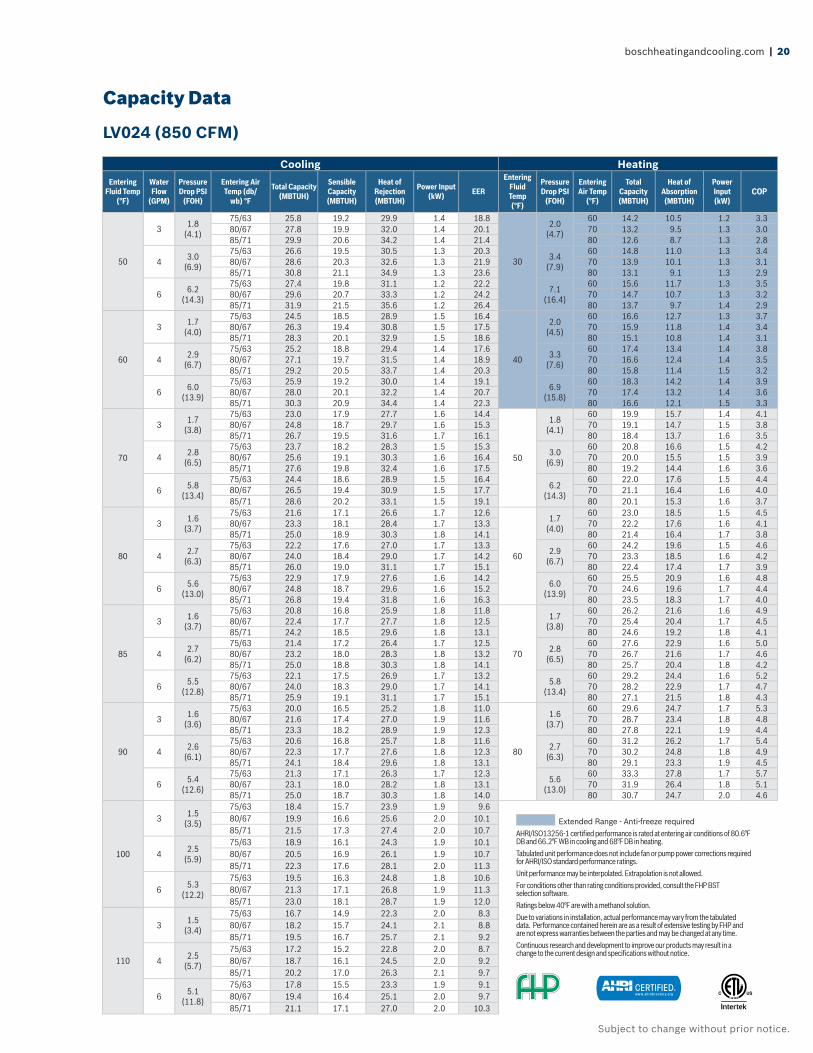
Capacity Data
LV024 (850 CFM)
Cooling Heating
Entering Fluid Temp
(°F)
Water Flow
(GPM)
Pressure Drop PSI
(FOH)
Entering Air Temp (db/
wb) °F
Total Capacity (MBTUH)
Sensible Capacity (MBTUH)
Heat of Rejection (MBTUH)
Power Input (kW) EER
Entering Fluid Temp (°F)
Pressure Drop PSI
(FOH)
Entering Air Temp
(°F)
Total Capacity (MBTUH)
Heat of Absorption
(MBTUH)
Power Input (kW)
COP
50
3 1.8(4.1)
75/63 25.8 19.2 29.9 1.4 18.8
30
2.0(4.7)
60 14.2 10.5 1.2 3.380/67 27.8 19.9 32.0 1.4 20.1 70 13.2 9.5 1.3 3.085/71 29.9 20.6 34.2 1.4 21.4 80 12.6 8.7 1.3 2.8
4 3.0(6.9)
75/63 26.6 19.5 30.5 1.3 20.3 3.4(7.9)
60 14.8 11.0 1.3 3.480/67 28.6 20.3 32.6 1.3 21.9 70 13.9 10.1 1.3 3.185/71 30.8 21.1 34.9 1.3 23.6 80 13.1 9.1 1.3 2.9
6 6.2(14.3)
75/63 27.4 19.8 31.1 1.2 22.2 7.1(16.4)
60 15.6 11.7 1.3 3.580/67 29.6 20.7 33.3 1.2 24.2 70 14.7 10.7 1.3 3.285/71 31.9 21.5 35.6 1.2 26.4 80 13.7 9.7 1.4 2.9
60
3 1.7(4.0)
75/63 24.5 18.5 28.9 1.5 16.4
40
2.0(4.5)
60 16.6 12.7 1.3 3.780/67 26.3 19.4 30.8 1.5 17.5 70 15.9 11.8 1.4 3.485/71 28.3 20.1 32.9 1.5 18.6 80 15.1 10.8 1.4 3.1
4 2.9(6.7)
75/63 25.2 18.8 29.4 1.4 17.6 3.3(7.6)
60 17.4 13.4 1.4 3.880/67 27.1 19.7 31.5 1.4 18.9 70 16.6 12.4 1.4 3.585/71 29.2 20.5 33.7 1.4 20.3 80 15.8 11.4 1.5 3.2
6 6.0(13.9)
75/63 25.9 19.2 30.0 1.4 19.1 6.9(15.8)
60 18.3 14.2 1.4 3.980/67 28.0 20.1 32.2 1.4 20.7 70 17.4 13.2 1.4 3.685/71 30.3 20.9 34.4 1.4 22.3 80 16.6 12.1 1.5 3.3
70
3 1.7(3.8)
75/63 23.0 17.9 27.7 1.6 14.4
50
1.8(4.1)
60 19.9 15.7 1.4 4.180/67 24.8 18.7 29.7 1.6 15.3 70 19.1 14.7 1.5 3.885/71 26.7 19.5 31.6 1.7 16.1 80 18.4 13.7 1.6 3.5
4 2.8(6.5)
75/63 23.7 18.2 28.3 1.5 15.3 3.0(6.9)
60 20.8 16.6 1.5 4.280/67 25.6 19.1 30.3 1.6 16.4 70 20.0 15.5 1.5 3.985/71 27.6 19.8 32.4 1.6 17.5 80 19.2 14.4 1.6 3.6
6 5.8(13.4)
75/63 24.4 18.6 28.9 1.5 16.46.2
(14.3)
60 22.0 17.6 1.5 4.480/67 26.5 19.4 30.9 1.5 17.7 70 21.1 16.4 1.6 4.085/71 28.6 20.2 33.1 1.5 19.1 80 20.1 15.3 1.6 3.7
80
3 1.6(3.7)
75/63 21.6 17.1 26.6 1.7 12.6
60
1.7(4.0)
60 23.0 18.5 1.5 4.580/67 23.3 18.1 28.4 1.7 13.3 70 22.2 17.6 1.6 4.185/71 25.0 18.9 30.3 1.8 14.1 80 21.4 16.4 1.7 3.8
4 2.7(6.3)
75/63 22.2 17.6 27.0 1.7 13.3 2.9(6.7)
60 24.2 19.6 1.5 4.680/67 24.0 18.4 29.0 1.7 14.2 70 23.3 18.5 1.6 4.285/71 26.0 19.0 31.1 1.7 15.1 80 22.4 17.4 1.7 3.9
6 5.6(13.0)
75/63 22.9 17.9 27.6 1.6 14.2 6.0(13.9)
60 25.5 20.9 1.6 4.880/67 24.8 18.7 29.6 1.6 15.2 70 24.6 19.6 1.7 4.485/71 26.8 19.4 31.8 1.6 16.3 80 23.5 18.3 1.7 4.0
85
3 1.6(3.7)
75/63 20.8 16.8 25.9 1.8 11.8
70
1.7(3.8)
60 26.2 21.6 1.6 4.980/67 22.4 17.7 27.7 1.8 12.5 70 25.4 20.4 1.7 4.585/71 24.2 18.5 29.6 1.8 13.1 80 24.6 19.2 1.8 4.1
4 2.7(6.2)
75/63 21.4 17.2 26.4 1.7 12.5 2.8(6.5)
60 27.6 22.9 1.6 5.080/67 23.2 18.0 28.3 1.8 13.2 70 26.7 21.6 1.7 4.685/71 25.0 18.8 30.3 1.8 14.1 80 25.7 20.4 1.8 4.2
6 5.5(12.8)
75/63 22.1 17.5 26.9 1.7 13.2 5.8(13.4)
60 29.2 24.4 1.6 5.280/67 24.0 18.3 29.0 1.7 14.1 70 28.2 22.9 1.7 4.785/71 25.9 19.1 31.1 1.7 15.1 80 27.1 21.5 1.8 4.3
90
3 1.6(3.6)
75/63 20.0 16.5 25.2 1.8 11.0
80
1.6(3.7)
60 29.6 24.7 1.7 5.380/67 21.6 17.4 27.0 1.9 11.6 70 28.7 23.4 1.8 4.885/71 23.3 18.2 28.9 1.9 12.3 80 27.8 22.1 1.9 4.4
4 2.6(6.1)
75/63 20.6 16.8 25.7 1.8 11.6 2.7(6.3)
60 31.2 26.2 1.7 5.480/67 22.3 17.7 27.6 1.8 12.3 70 30.2 24.8 1.8 4.985/71 24.1 18.4 29.6 1.8 13.1 80 29.1 23.3 1.9 4.5
6 5.4(12.6)
75/63 21.3 17.1 26.3 1.7 12.3 5.6(13.0)
60 33.3 27.8 1.7 5.780/67 23.1 18.0 28.2 1.8 13.1 70 31.9 26.4 1.8 5.185/71 25.0 18.7 30.3 1.8 14.0 80 30.7 24.7 2.0 4.6
100
3 1.5(3.5)
75/63 18.4 15.7 23.9 1.9 9.680/67 19.9 16.6 25.6 2.0 10.185/71 21.5 17.3 27.4 2.0 10.7
4 2.5(5.9)
75/63 18.9 16.1 24.3 1.9 10.180/67 20.5 16.9 26.1 1.9 10.785/71 22.3 17.6 28.1 2.0 11.3
6 5.3(12.2)
75/63 19.5 16.3 24.8 1.8 10.680/67 21.3 17.1 26.8 1.9 11.385/71 23.0 18.1 28.7 1.9 12.0
110
3 1.5(3.4)
75/63 16.7 14.9 22.3 2.0 8.380/67 18.2 15.7 24.1 2.1 8.885/71 19.5 16.7 25.7 2.1 9.2
4 2.5(5.7)
75/63 17.2 15.2 22.8 2.0 8.780/67 18.7 16.1 24.5 2.0 9.285/71 20.2 17.0 26.3 2.1 9.7
6 5.1(11.8)
75/63 17.8 15.5 23.3 1.9 9.180/67 19.4 16.4 25.1 2.0 9.785/71 21.1 17.1 27.0 2.0 10.3
Extended Range - Anti-freeze requiredAHRI/ISO13256-1 certifi ed performance is rated at entering air conditions of 80.6°F DB and 66.2°F WB in cooling and 68°F DB in heating.Tabulated unit performance does not include fan or pump power corrections required for AHRI/ISO standard performance ratings.Unit performance may be interpolated. Extrapolation is not allowed.For conditions other than rating conditions provided, consult the FHP BST selection software. Ratings below 40°F are with a methanol solution.Due to variations in installation, actual performance may vary from the tabulated data. Performance contained herein are as a result of extensive testing by FHP and are not express warranties between the parties and may be changed at any time.Continuous research and development to improve our products may result in a change to the current design and specifi cations without notice.
®
21 | LV Split Systems | Commercial Geothermal Heat Pumps
Subject to change without prior notice.
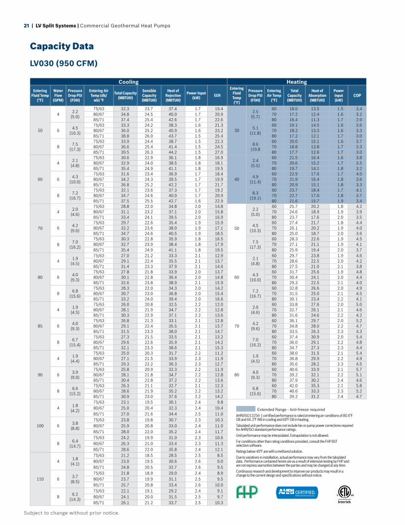
Capacity Data
LV030 (950 CFM)
Cooling Heating
Entering Fluid Temp
(°F)
Water Flow
(GPM)
Pressure Drop PSI
(FOH)
Entering Air Temp (db/
wb) °F
Total Capacity (MBTUH)
Sensible Capacity (MBTUH)
Heat of Rejection (MBTUH)
Power Input (kW) EER
Entering Fluid Temp (°F)
Pressure Drop PSI
(FOH)
Entering Air Temp
(°F)
Total Capacity (MBTUH)
Heat of Absorption
(MBTUH)
Power Input (kW)
COP
50
4 2.2(5.0)
75/63 32.3 23.7 37.4 1.7 19.4
30
2.5(5.7)
60 18.0 13.5 1.5 3.480/67 34.8 24.5 40.0 1.7 20.9 70 17.2 12.4 1.6 3.285/71 37.4 25.4 42.6 1.7 22.6 80 16.4 11.3 1.7 2.9
6 4.5(10.3)
75/63 33.3 24.2 38.3 1.6 21.3 5.1(11.8)
60 19.1 14.5 1.6 3.680/67 36.0 25.2 40.9 1.6 23.2 70 18.2 13.3 1.6 3.385/71 38.8 26.0 43.7 1.5 25.4 80 17.2 12.1 1.7 3.0
8 7.5(17.3)
75/63 33.9 24.4 38.7 1.5 22.3 8.6(19.8
60 20.0 15.1 1.6 3.780/67 36.6 25.4 41.4 1.5 24.5 70 18.8 13.8 1.7 3.385/71 39.5 26.3 44.2 1.5 27.0 80 17.7 12.6 1.7 3.0
60
4 2.1(4.8)
75/63 30.6 22.9 36.1 1.8 16.9
40
2.4(5.5)
60 21.5 16.4 1.6 3.880/67 32.9 24.0 38.5 1.8 18.1 70 20.6 15.2 1.7 3.585/71 35.4 24.9 41.1 1.8 19.5 80 19.7 14.1 1.8 3.2
6 4.3(10.0)
75/63 31.6 23.4 36.9 1.7 18.4 4.9(11.4)
60 22.9 17.6 1.7 4.080/67 34.2 24.3 39.5 1.7 19.9 70 21.9 16.4 1.8 3.685/71 36.8 25.2 42.2 1.7 21.7 80 20.9 15.1 1.8 3.3
8 7.2(16.7)
75/63 32.1 23.6 37.3 1.7 19.2 8.3(19.1)
60 23.7 18.4 1.7 4.180/67 34.7 24.6 40.0 1.7 20.9 70 22.7 17.0 1.8 3.785/71 37.5 25.5 42.7 1.6 22.9 80 21.6 15.7 1.9 3.4
70
4 2.0(4.6)
75/63 28.8 22.0 34.8 2.0 14.8
50
2.2(5.0)
60 25.7 20.2 1.8 4.280/67 31.1 23.2 37.1 2.0 15.8 70 24.6 18.9 1.9 3.985/71 33.4 24.1 39.5 2.0 16.9 80 23.7 17.6 2.0 3.5
6 4.2(9.6)
75/63 29.7 22.6 35.4 1.9 15.9 4.5(10.3)
60 27.4 21.7 1.8 4.480/67 32.2 23.6 38.0 1.9 17.1 70 26.1 20.2 1.9 4.085/71 34.7 24.6 40.5 1.9 18.5 80 25.0 18.7 2.0 3.6
8 7.0(16.2)
75/63 30.3 22.8 35.9 1.8 16.57.5
(17.3)
60 28.3 22.6 1.9 4.580/67 32.7 23.9 38.4 1.8 17.9 70 27.1 21.1 1.9 4.185/71 35.4 24.9 41.1 1.8 19.5 80 25.9 19.4 2.0 3.7
80
4 1.9(4.5)
75/63 27.0 21.2 33.3 2.1 12.9
60
2.1(4.8)
60 29.7 23.8 1.9 4.680/67 29.1 22.4 35.5 2.1 13.7 70 28.6 22.5 2.0 4.285/71 31.4 23.3 37.9 2.1 14.6 80 27.5 21.0 2.1 3.8
6 4.0(9.3)
75/63 27.8 21.8 33.9 2.0 13.7 4.3(10.0)
60 31.7 25.6 1.9 4.880/67 30.1 22.8 36.4 2.0 14.8 70 30.4 24.1 2.0 4.485/71 32.6 23.8 38.9 2.1 15.9 80 29.3 22.5 2.1 4.0
8 6.8(15.6)
75/63 28.3 22.0 34.3 2.0 14.2 7.2(16.7)
60 32.8 26.6 2.0 4.980/67 30.7 23.0 36.8 2.0 15.4 70 31.5 25.0 2.1 4.585/71 33.2 24.0 39.4 2.0 16.6 80 30.1 23.4 2.2 4.1
85
4 1.9(4.5)
75/63 26.0 20.8 32.5 2.2 12.0
70
2.0(4.6)
60 33.8 27.6 2.0 5.080/67 28.1 21.9 34.7 2.2 12.8 70 32.7 26.1 2.1 4.685/71 30.3 22.9 37.1 2.2 13.6 80 31.6 24.6 2.2 4.2
6 4.0(9.3)
75/63 26.8 21.3 33.1 2.1 12.8 4.2(9.6)
60 36.1 29.7 2.0 5.280/67 29.1 22.4 35.5 2.1 13.7 70 34.8 28.0 2.2 4.785/71 31.5 23.3 38.0 2.1 14.7 80 33.5 26.3 2.3 4.3
8 6.7(15.4)
75/63 27.3 21.5 33.5 2.1 13.2 7.0(16.2)
60 37.4 30.9 2.0 5.480/67 29.6 22.6 35.9 2.1 14.2 70 36.0 29.1 2.2 4.885/71 32.1 23.3 38.6 2.1 15.3 80 34.7 27.3 2.3 4.4
90
4 1.9(4.4)
75/63 25.0 20.3 31.7 2.2 11.2
80
1.9(4.5)
60 38.0 31.5 2.1 5.480/67 27.1 21.5 33.9 2.3 11.9 70 36.8 29.9 2.2 4.985/71 29.3 22.2 36.3 2.3 12.7 80 35.6 28.2 2.3 4.5
6 3.9(9.0)
75/63 25.8 20.9 32.3 2.2 11.9 4.0(9.3)
60 40.6 33.9 2.1 5.780/67 28.1 21.8 34.7 2.2 12.8 70 39.2 32.1 2.2 5.185/71 30.4 22.8 37.2 2.2 13.6 80 37.9 30.2 2.4 4.6
8 6.6(15.2)
75/63 26.3 21.1 32.7 2.1 12.3 6.8(15.6)
60 42.0 35.3 2.1 5.880/67 28.6 21.9 35.2 2.2 13.2 70 40.6 33.3 2.3 5.285/71 30.9 23.0 37.6 2.2 14.2 80 39.2 31.2 2.4 4.7
100
4 1.8(4.2)
75/63 23.1 19.5 30.1 2.4 9.880/67 25.0 20.4 32.3 2.4 10.485/71 27.0 21.6 34.4 2.5 11.0
6 3.8(8.8)
75/63 23.8 19.8 30.7 2.3 10.380/67 25.9 20.8 33.0 2.4 11.085/71 28.0 22.0 35.2 2.4 11.7
8 6.4(14.7)
75/63 24.2 19.9 31.0 2.3 10.680/67 26.3 21.0 33.4 2.3 11.385/71 28.6 22.0 35.8 2.4 12.1
110
4 1.8(4.1)
75/63 21.2 18.5 28.5 2.5 8.580/67 23.0 19.5 30.6 2.6 9.085/71 24.8 20.5 32.7 2.6 9.5
6 3.7(8.5)
75/63 21.8 18.9 29.0 2.4 8.980/67 23.7 19.9 31.1 2.5 9.585/71 25.7 20.8 33.4 2.6 10.0
8 6.2(14.3)
75/63 22.1 19.1 29.2 2.4 9.180/67 24.1 20.0 31.5 2.5 9.785/71 26.1 21.2 33.7 2.5 10.3
Extended Range - Anti-freeze requiredAHRI/ISO13256-1 certifi ed performance is rated at entering air conditions of 80.6°F DB and 66.2°F WB in cooling and 68°F DB in heating.Tabulated unit performance does not include fan or pump power corrections required for AHRI/ISO standard performance ratings.Unit performance may be interpolated. Extrapolation is not allowed.For conditions other than rating conditions provided, consult the FHP BST selection software. Ratings below 40°F are with a methanol solution.Due to variations in installation, actual performance may vary from the tabulated data. Performance contained herein are as a result of extensive testing by FHP and are not express warranties between the parties and may be changed at any time.Continuous research and development to improve our products may result in a change to the current design and specifi cations without notice.
®
boschheatingandcooling.com | 22
Subject to change without prior notice.
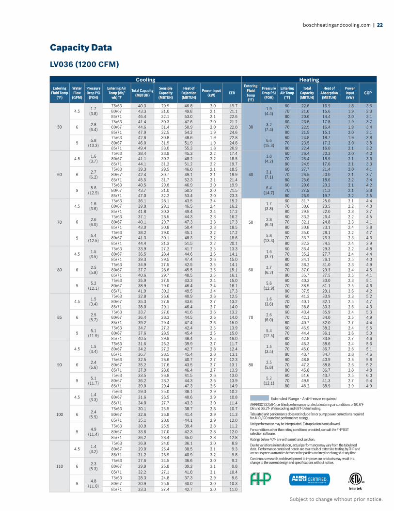
Capacity Data
LV036 (1200 CFM)
Cooling Heating
Entering Fluid Temp
(°F)
Water Flow
(GPM)
Pressure Drop PSI
(FOH)
Entering Air Temp (db/
wb) °F
Total Capacity (MBTUH)
Sensible Capacity (MBTUH)
Heat of Rejection (MBTUH)
Power Input (kW) EER
Entering Fluid Temp (°F)
Pressure Drop PSI
(FOH)
Entering Air Temp
(°F)
Total Capacity (MBTUH)
Heat of Absorption
(MBTUH)
Power Input (kW)
COP
50
4.5 1.7(3.8)
75/63 40.3 29.9 46.8 2.0 19.7
30
1.9(4.4)
60 22.6 16.9 1.8 3.680/67 43.3 31.0 49.8 2.1 21.1 70 21.6 15.6 1.9 3.385/71 46.4 32.1 53.0 2.1 22.6 80 20.6 14.4 2.0 3.1
6 2.8(6.4)
75/63 41.4 30.3 47.6 2.0 21.2 3.2(7.4)
60 23.6 17.8 1.9 3.780/67 44.6 31.4 50.9 2.0 22.8 70 22.5 16.4 1.9 3.485/71 47.9 32.5 54.2 1.9 24.6 80 21.5 15.1 2.0 3.1
9 5.8(13.3)
75/63 42.6 30.8 48.6 1.9 22.8 6.6(15.3)
60 24.8 18.7 1.9 3.880/67 46.0 31.9 51.9 1.9 24.8 70 23.5 17.2 2.0 3.585/71 49.4 33.0 55.3 1.8 26.9 80 22.4 16.0 2.1 3.2
60
4.5 1.6(3.7)
75/63 38.4 28.9 45.3 2.2 17.4
40
1.8(4.2)
60 26.4 20.3 2.0 4.080/67 41.1 30.2 48.2 2.2 18.5 70 25.4 18.9 2.1 3.685/71 44.1 31.2 51.2 2.2 19.7 80 24.5 17.6 2.1 3.3
6 2.7(6.2)
75/63 39.3 29.5 46.0 2.1 18.5 3.1(7.1)
60 27.7 21.4 2.0 4.180/67 42.4 30.7 49.1 2.1 19.9 70 26.5 20.0 2.1 3.785/71 45.5 31.7 52.3 2.1 21.4 80 25.6 18.6 2.2 3.4
9 5.6(12.9)
75/63 40.5 29.8 46.9 2.0 19.9 6.4(14.7)
60 29.6 23.2 2.1 4.280/67 43.7 31.0 50.2 2.0 21.5 70 27.9 21.2 2.1 3.885/71 47.0 32.2 53.4 2.0 23.3 80 26.9 19.7 2.2 3.5
70
4.5 1.6(3.6)
75/63 36.1 28.1 43.5 2.4 15.2
50
1.7(3.8)
60 31.7 25.0 2.1 4.480/67 39.0 29.1 46.5 2.4 16.2 70 30.6 23.5 2.2 4.085/71 41.8 30.3 49.4 2.4 17.2 80 29.5 22.0 2.3 3.7
6 2.6(6.0)
75/63 37.1 28.5 44.3 2.3 16.2 2.8(6.4)
60 33.2 26.4 2.2 4.580/67 40.1 29.7 47.3 2.3 17.3 70 32.1 24.8 2.3 4.185/71 43.0 30.8 50.4 2.3 18.5 80 30.8 23.1 2.4 3.8
9 5.4(12.5)
75/63 38.2 29.0 45.1 2.2 17.25.8
(13.3)
60 35.0 28.1 2.2 4.780/67 41.3 30.1 48.3 2.2 18.6 70 33.7 26.3 2.3 4.385/71 44.4 31.3 51.5 2.2 20.1 80 32.3 24.5 2.4 3.9
80
4.5 1.5(3.5)
75/63 33.9 27.2 41.7 2.5 13.3
60
1.6(3.7)
60 36.4 29.3 2.2 4.880/67 36.5 28.4 44.6 2.6 14.1 70 35.2 27.7 2.4 4.485/71 39.3 29.5 47.4 2.6 15.0 80 34.1 26.1 2.5 4.0
6 2.5(5.8)
75/63 34.9 27.5 42.5 2.5 14.1 2.7(6.2)
60 38.2 31.0 2.3 4.980/67 37.7 28.6 45.5 2.5 15.1 70 37.0 29.3 2.4 4.585/71 40.6 29.7 48.5 2.5 16.1 80 35.7 27.5 2.5 4.1
9 5.2(12.1)
75/63 35.9 27.9 43.3 2.4 15.0 5.6(12.9)
60 40.3 33.0 2.3 5.180/67 38.9 29.0 46.4 2.4 16.1 70 38.9 31.1 2.5 4.685/71 41.9 30.2 49.5 2.4 17.3 80 37.5 29.1 2.6 4.2
85
4.5 1.5(3.4)
75/63 32.8 26.6 40.9 2.6 12.5
70
1.6(3.6)
60 41.3 33.9 2.3 5.280/67 35.3 27.9 43.6 2.7 13.2 70 40.1 32.1 2.5 4.785/71 38.0 29.1 46.4 2.7 14.0 80 38.8 30.3 2.6 4.3
6 2.5(5.7)
75/63 33.7 27.0 41.6 2.6 13.2 2.6(6.0)
60 43.4 35.9 2.4 5.380/67 36.4 28.3 44.5 2.6 14.0 70 42.1 34.0 2.5 4.985/71 39.2 29.4 47.4 2.6 15.0 80 40.7 32.0 2.7 4.4
9 5.1(11.9)
75/63 34.7 27.3 42.4 2.5 13.9 5.4(12.5)
60 45.9 38.2 2.4 5.580/67 37.6 28.5 45.4 2.5 15.0 70 44.4 36.1 2.6 5.085/71 40.5 29.9 48.4 2.5 16.0 80 42.8 33.9 2.7 4.6
90
4.5 1.5(3.4)
75/63 31.6 26.2 39.9 2.7 11.7
80
1.5(3.5)
60 46.3 38.6 2.4 5.680/67 34.2 27.2 42.7 2.8 12.4 70 45.0 36.7 2.6 5.185/71 36.7 28.5 45.4 2.8 13.1 80 43.7 34.7 2.8 4.6
6 2.4(5.6)
75/63 32.5 26.6 40.7 2.7 12.3 2.5(5.8)
60 48.8 40.9 2.5 5.880/67 35.2 27.6 43.5 2.7 13.1 70 47.3 38.8 2.6 5.285/71 37.9 28.8 46.4 2.7 13.9 80 45.8 36.7 2.8 4.8
9 5.1(11.7)
75/63 33.5 26.8 41.5 2.6 13.0 5.2(12.1)
60 51.6 43.7 2.5 6.080/67 36.2 28.2 44.3 2.6 13.9 70 49.9 41.3 2.7 5.485/71 39.0 29.4 47.3 2.6 14.9 80 48.2 38.9 2.9 4.9
100
4.5 1.4(3.3)
75/63 29.3 25.0 38.1 2.9 10.280/67 31.6 26.5 40.6 2.9 10.885/71 34.0 27.7 43.3 3.0 11.4
6 2.4(5.5)
75/63 30.1 25.5 38.7 2.8 10.780/67 32.6 26.8 41.4 2.9 11.385/71 35.1 28.0 44.1 2.9 12.0
9 4.9(11.4)
75/63 30.9 25.9 39.4 2.8 11.280/67 33.6 27.0 42.3 2.8 12.085/71 36.2 28.4 45.0 2.8 12.8
110
4.5 1.4(3.2)
75/63 26.9 24.0 36.1 3.0 8.980/67 29.0 25.4 38.5 3.1 9.385/71 31.2 26.9 40.9 3.2 9.8
6 2.3(5.3)
75/63 27.6 24.5 36.6 3.0 9.280/67 29.9 25.8 39.2 3.1 9.885/71 32.2 27.1 41.8 3.1 10.4
9 4.8(11.0)
75/63 28.3 24.8 37.3 2.9 9.680/67 30.9 25.9 40.0 3.0 10.385/71 33.3 27.4 42.7 3.0 11.0
Extended Range - Anti-freeze requiredAHRI/ISO13256-1 certifi ed performance is rated at entering air conditions of 80.6°F DB and 66.2°F WB in cooling and 68°F DB in heating.Tabulated unit performance does not include fan or pump power corrections required for AHRI/ISO standard performance ratings.Unit performance may be interpolated. Extrapolation is not allowed.For conditions other than rating conditions provided, consult the FHP BST selection software. Ratings below 40°F are with a methanol solution.Due to variations in installation, actual performance may vary from the tabulated data. Performance contained herein are as a result of extensive testing by FHP and are not express warranties between the parties and may be changed at any time.Continuous research and development to improve our products may result in a change to the current design and specifi cations without notice.
®

23 | LV Split Systems | Commercial Geothermal Heat Pumps
Subject to change without prior notice.
Capacity Data
LV042 (1400 CFM)
Cooling Heating
Entering Fluid Temp
(°F)
Water Flow
(GPM)
Pressure Drop PSI
(FOH)
Entering Air Temp (db/
wb) °F
Total Capacity (MBTUH)
Sensible Capacity (MBTUH)
Heat of Rejection (MBTUH)
Power Input (kW) EER
Entering Fluid Temp (°F)
Pressure Drop PSI
(FOH)
Entering Air Temp
(°F)
Total Capacity (MBTUH)
Heat of Absorption
(MBTUH)
Power Input (kW)
COP
50
5 2.1(4.9)
75/63 44.0 33.2 51.5 2.4 18.6
30
2.4(5.6)
60 25.2 18.0 2.3 3.380/67 47.4 34.5 55.0 2.4 20.0 70 24.4 17.0 2.3 3.185/71 50.9 35.6 58.6 2.4 21.4 80 23.5 15.8 2.4 2.9
8 4.9(11.4)
75/63 45.8 34.0 52.8 2.2 21.0 5.6(13.0)
60 26.9 19.8 2.3 3.480/67 49.5 35.2 56.5 2.2 22.9 70 25.9 18.5 2.4 3.285/71 53.3 36.4 60.3 2.1 24.9 80 25.0 17.1 2.5 3.0
11 8.8(20.2)
75/63 46.7 34.3 53.4 2.1 22.3 10.0(23.1)
60 28.1 20.6 2.3 3.580/67 50.5 35.6 57.3 2.1 24.5 70 26.9 19.4 2.4 3.385/71 54.5 36.8 61.2 2.0 26.9 80 25.9 17.8 2.5 3.0
60
5 2.0(4.7)
75/63 41.7 32.2 49.9 2.6 16.3
40
2.3(5.4)
60 29.5 22.2 2.4 3.780/67 45.0 33.4 53.3 2.6 17.4 70 28.9 20.9 2.5 3.485/71 48.4 34.6 56.8 2.6 18.5 80 27.9 19.6 2.6 3.2
8 4.8(11.0)
75/63 43.6 32.8 51.2 2.4 18.1 5.5(12.6)
60 32.0 24.2 2.4 3.980/67 47.1 34.1 54.8 2.4 19.6 70 30.9 22.8 2.5 3.685/71 50.7 35.4 58.5 2.4 21.2 80 29.9 21.3 2.6 3.3
11 8.5(19.6)
75/63 44.4 33.2 51.9 2.3 19.1 9.7(22.3)
60 33.3 25.4 2.5 4.080/67 48.1 34.5 55.5 2.3 20.8 70 32.1 23.8 2.6 3.785/71 51.8 35.8 59.3 2.3 22.6 80 31.0 22.3 2.7 3.4
70
5 2.0(4.6)
75/63 39.5 31.1 48.2 2.8 14.2
50
2.1(4.9)
60 35.4 27.5 2.5 4.180/67 42.6 32.3 51.5 2.8 15.1 70 34.4 26.0 2.6 3.885/71 45.7 33.6 54.8 2.9 16.0 80 33.5 24.5 2.8 3.5
8 4.6(10.7)
75/63 41.2 31.8 49.5 2.6 15.7 4.9(11.4)
60 38.2 30.0 2.6 4.480/67 44.4 33.3 52.9 2.6 16.8 70 37.1 28.3 2.7 4.085/71 47.9 34.4 56.5 2.7 18.1 80 35.8 26.8 2.8 3.7
11 8.2(18.9)
75/63 42.0 32.0 50.1 2.6 16.48.8
(20.2)
60 39.7 31.3 2.6 4.580/67 45.4 33.5 53.6 2.6 17.7 70 38.4 29.5 2.7 4.185/71 48.9 35.0 57.2 2.6 19.2 80 37.0 27.9 2.9 3.8
80
5 1.9(4.4)
75/63 37.0 30.1 46.4 3.0 12.4
60
2.0(4.7)
60 40.9 32.5 2.6 4.680/67 40.0 31.3 49.6 3.0 13.2 70 39.8 30.9 2.8 4.285/71 42.8 32.9 52.6 3.1 13.9 80 38.4 29.1 2.9 3.8
8 4.5(10.3)
75/63 38.6 30.8 47.6 2.9 13.5 4.8(11.0)
60 44.1 35.5 2.7 4.880/67 41.8 32.1 50.9 2.9 14.5 70 42.8 33.5 2.9 4.485/71 45.1 33.3 54.3 2.9 15.5 80 41.4 31.5 3.0 4.0
11 7.9(18.3)
75/63 39.4 31.0 48.2 2.8 14.1 8.5(19.6)
60 45.8 37.1 2.7 4.980/67 42.6 32.6 51.5 2.8 15.2 70 44.3 35.0 2.9 4.585/71 46.1 33.7 55.1 2.8 16.3 80 42.8 32.8 3.1 4.1
85
5 1.9(4.4)
75/63 35.8 29.5 45.5 3.1 11.6
70
2.0(4.6)
60 46.4 37.6 2.7 5.080/67 38.6 31.0 48.5 3.1 12.3 70 45.2 35.7 2.9 4.585/71 41.4 32.3 51.5 3.2 13.0 80 43.9 33.8 3.1 4.2
8 4.4(10.2)
75/63 37.3 30.2 46.6 3.0 12.6 4.6(10.7)
60 50.2 41.1 2.8 5.280/67 40.4 31.7 49.8 3.0 13.5 70 48.7 38.9 3.0 4.885/71 43.5 33.0 53.1 3.0 14.4 80 47.0 36.7 3.2 4.3
11 7.8(18.0)
75/63 38.0 30.5 47.1 2.9 13.1 8.2(18.9)
60 52.2 43.0 2.8 5.480/67 41.2 32.0 50.5 2.9 14.1 70 50.5 40.6 3.0 4.985/71 44.5 33.2 53.9 3.0 15.1 80 48.8 38.2 3.2 4.4
90
5 1.9(4.3)
75/63 34.5 29.1 44.5 3.2 10.8
80
1.9(4.4)
60 52.2 42.9 2.8 5.480/67 37.3 30.5 47.4 3.2 11.5 70 50.9 40.8 3.1 4.985/71 40.0 31.9 50.4 3.3 12.1 80 49.4 38.7 3.3 4.4
8 4.3(10.0)
75/63 36.0 29.7 45.6 3.1 11.7 4.5(10.3)
60 56.5 47.0 2.9 5.780/67 39.0 31.0 48.8 3.1 12.5 70 54.7 44.5 3.1 5.185/71 42.0 32.5 51.9 3.2 13.3 80 53.1 42.0 3.4 4.6
11 7.7(17.7)
75/63 36.7 30.0 46.1 3.0 12.2 7.9(18.3)
60 58.8 49.1 3.0 5.880/67 39.8 31.3 49.4 3.0 13.1 70 56.8 46.5 3.2 5.285/71 42.9 32.9 52.7 3.1 14.0 80 54.9 43.7 3.4 4.7
100
5 1.8(4.2)
75/63 31.9 28.0 42.4 3.4 9.480/67 34.5 29.4 45.3 3.5 10.085/71 37.1 30.7 48.1 3.5 10.5
8 4.2(9.7)
75/63 33.3 28.6 43.5 3.3 10.280/67 36.1 29.9 46.6 3.3 10.885/71 38.9 31.4 49.5 3.4 11.5
11 7.5(17.2)
75/63 34.0 28.7 44.1 3.2 10.580/67 36.9 30.2 47.2 3.3 11.285/71 39.7 31.7 50.2 3.3 11.9
110
5 1.8(4.0)
75/63 29.3 26.7 40.3 3.6 8.280/67 31.5 28.4 42.8 3.7 8.685/71 33.9 29.8 45.6 3.7 9.1
8 4.1(9.4)
75/63 30.5 27.4 41.3 3.5 8.880/67 33.0 29.0 44.0 3.6 9.385/71 35.6 30.4 47.0 3.6 9.8
11 7.2(16.7)
75/63 31.1 27.5 41.8 3.4 9.080/67 33.8 28.9 44.7 3.5 9.685/71 36.4 30.6 47.6 3.6 10.2
Extended Range - Anti-freeze requiredAHRI/ISO13256-1 certifi ed performance is rated at entering air conditions of 80.6°F DB and 66.2°F WB in cooling and 68°F DB in heating.Tabulated unit performance does not include fan or pump power corrections required for AHRI/ISO standard performance ratings.Unit performance may be interpolated. Extrapolation is not allowed.For conditions other than rating conditions provided, consult the FHP BST selection software. Ratings below 40°F are with a methanol solution.Due to variations in installation, actual performance may vary from the tabulated data. Performance contained herein are as a result of extensive testing by FHP and are not express warranties between the parties and may be changed at any time.Continuous research and development to improve our products may result in a change to the current design and specifi cations without notice.
®

boschheatingandcooling.com | 24
Subject to change without prior notice.
Capacity Data
LV048 (1600 CFM)
Cooling Heating
Entering Fluid Temp
(°F)
Water Flow
(GPM)
Pressure Drop PSI
(FOH)
Entering Air Temp (db/
wb) °F
Total Capacity (MBTUH)
Sensible Capacity (MBTUH)
Heat of Rejection (MBTUH)
Power Input (kW) EER
Entering Fluid Temp (°F)
Pressure Drop PSI
(FOH)
Entering Air Temp
(°F)
Total Capacity (MBTUH)
Heat of Absorption
(MBTUH)
Power Input (kW)
COP
50
6 0.9(2.0)
75/63 51.3 37.7 60.3 2.8 18.3
30
1.0(2.3)
60 33.2 25.2 2.5 3.980/67 54.7 39.1 63.9 2.8 19.4 70 30.9 22.3 2.6 3.585/71 58.3 40.3 67.6 2.8 20.6 80 28.6 19.6 2.7 3.1
8 1.4(3.3)
75/63 52.9 38.4 61.5 2.7 19.9 1.7(3.8)
60 34.4 26.2 2.6 3.980/67 56.5 39.7 65.2 2.7 21.2 70 32.0 23.3 2.7 3.585/71 60.3 40.8 69.1 2.7 22.6 80 29.7 20.6 2.8 3.1
12 3.0(6.9)
75/63 54.7 39.1 62.9 2.5 21.7 3.4(7.9)
60 35.9 27.5 2.6 4.080/67 58.4 40.4 66.6 2.5 23.4 70 33.4 24.7 2.8 3.685/71 62.4 41.5 70.6 2.5 25.2 80 30.9 21.9 2.9 3.2
60
6 0.8(1.9)
75/63 48.6 36.2 58.3 3.0 16.0
40
1.0(2.2)
60 37.0 28.4 2.7 4.080/67 51.9 37.9 61.7 3.1 16.9 70 35.1 25.8 2.8 3.685/71 55.4 39.2 65.4 3.1 17.9 80 33.1 23.4 2.9 3.3
8 1.4(3.2)
75/63 50.0 37.2 59.3 2.9 17.2 1.6(3.7)
60 38.6 29.9 2.8 4.180/67 53.5 38.6 63.0 2.9 18.3 70 36.7 27.2 2.9 3.785/71 57.2 39.9 66.7 2.9 19.5 80 34.6 24.7 3.0 3.4
12 2.9(6.7)
75/63 51.6 37.9 60.5 2.8 18.6 3.3(7.7)
60 40.6 31.6 2.8 4.280/67 55.3 39.3 64.3 2.8 19.9 70 38.6 28.8 3.0 3.885/71 59.2 40.4 68.2 2.8 21.4 80 36.4 26.2 3.1 3.5
70
6 0.8(1.9)
75/63 45.7 35.1 56.1 3.3 14.0
50
0.9(2.0)
60 43.1 33.5 2.9 4.380/67 48.9 36.7 59.5 3.3 14.8 70 41.1 31.3 3.1 3.985/71 52.5 37.7 63.3 3.3 15.7 80 39.2 28.7 3.2 3.6
8 1.4(3.1)
75/63 47.0 35.9 57.1 3.1 14.9 1.4(3.3)
60 45.1 35.4 3.0 4.480/67 50.4 37.3 60.7 3.2 15.9 70 43.1 32.8 3.1 4.085/71 54.1 38.5 64.5 3.2 16.9 80 40.9 30.2 3.3 3.7
12 2.8(6.5)
75/63 48.5 36.5 58.2 3.0 16.03.0
(6.9)
60 47.4 37.4 3.1 4.580/67 52.1 38.0 61.9 3.0 17.1 70 45.2 34.9 3.2 4.185/71 55.9 39.1 65.8 3.1 18.3 80 43.1 32.0 3.4 3.8
80
6 0.8(1.8)
75/63 42.8 33.7 53.8 3.5 12.3
60
0.8(1.9)
60 48.6 38.6 3.1 4.680/67 45.9 35.4 57.2 3.5 13.0 70 46.7 36.3 3.3 4.285/71 49.1 37.0 60.7 3.6 13.7 80 45.2 33.8 3.4 3.8
8 1.3(3.0)
75/63 43.9 34.6 54.7 3.4 13.0 1.4(3.2)
60 51.0 40.7 3.2 4.780/67 47.4 35.9 58.3 3.4 13.8 70 49.1 38.1 3.3 4.385/71 50.9 37.1 62.1 3.5 14.7 80 47.3 35.6 3.5 3.9
12 2.7(6.3)
75/63 45.3 35.0 55.8 3.3 13.8 2.9(6.7)
60 53.8 43.2 3.2 4.980/67 48.9 36.4 59.5 3.3 14.8 70 51.7 40.4 3.4 4.485/71 52.6 37.7 63.3 3.3 15.8 80 49.7 37.8 3.6 4.0
85
6 0.8(1.8)
75/63 41.2 33.2 52.5 3.6 11.5
70
0.8(1.9)
60 54.5 44.0 3.3 4.980/67 44.4 34.6 56.1 3.7 12.1 70 53.0 41.5 3.5 4.585/71 47.7 36.0 59.6 3.7 12.8 80 51.1 39.2 3.7 4.1
8 1.3(3.0)
75/63 42.4 33.7 53.5 3.5 12.1 1.4(3.1)
60 57.3 46.5 3.3 5.080/67 45.8 35.1 57.2 3.6 12.9 70 55.5 43.9 3.5 4.685/71 49.2 36.5 60.8 3.6 13.7 80 53.8 41.3 3.7 4.2
12 2.7(6.2)
75/63 43.7 34.2 54.6 3.4 12.9 2.8(6.5)
60 60.6 49.4 3.4 5.280/67 47.3 35.6 58.3 3.4 13.7 70 58.5 46.6 3.6 4.785/71 50.8 37.1 62.0 3.5 14.6 80 56.5 43.8 3.8 4.3
90
6 0.8(1.7)
75/63 39.6 32.6 51.3 3.7 10.7
80
0.8(1.8)
60 60.7 49.8 3.4 5.280/67 42.8 34.0 54.8 3.8 11.4 70 59.0 47.3 3.6 4.785/71 46.0 35.6 58.3 3.8 12.0 80 57.5 44.7 3.9 4.4
8 1.3(2.9)
75/63 40.8 33.1 52.3 3.6 11.3 1.3(3.0)
60 64.0 52.7 3.5 5.480/67 44.1 34.6 55.8 3.7 12.0 70 61.9 49.9 3.7 4.985/71 47.5 36.1 59.4 3.7 12.7 80 60.4 47.2 4.0 4.5
12 2.6(6.1)
75/63 42.1 33.5 53.3 3.5 11.9 2.7(6.3)
60 67.8 56.0 3.6 5.680/67 45.5 35.0 57.0 3.6 12.7 70 65.7 53.1 3.8 5.185/71 49.0 36.7 60.6 3.6 13.6 80 63.6 50.1 4.0 4.6
100
6 0.7(1.7)
75/63 36.5 31.5 48.8 3.9 9.380/67 39.5 33.1 52.1 4.0 9.985/71 42.5 34.7 55.5 4.1 10.4
8 1.3(2.9)
75/63 37.6 31.6 49.7 3.8 9.880/67 40.8 33.4 53.2 3.9 10.485/71 44.1 34.7 56.8 4.0 11.0
12 2.6(5.9)
75/63 38.7 32.1 50.6 3.8 10.380/67 42.0 33.9 54.2 3.8 11.085/71 45.4 35.4 57.8 3.9 11.7
110
6 0.7(1.6)
75/63 33.6 30.0 46.6 4.1 8.280/67 36.5 31.6 49.8 4.2 8.685/71 39.2 33.4 53.0 4.3 9.1
8 1.2(2.8)
75/63 34.5 30.4 47.3 4.1 8.580/67 37.4 32.3 50.5 4.2 9.085/71 40.5 33.5 54.0 4.3 9.5
12 2.5(5.7)
75/63 35.4 30.8 48.0 4.0 8.980/67 38.4 32.6 51.3 4.1 9.485/71 41.8 33.8 55.0 4.2 10.0
Extended Range - Anti-freeze requiredAHRI/ISO13256-1 certifi ed performance is rated at entering air conditions of 80.6°F DB and 66.2°F WB in cooling and 68°F DB in heating.Tabulated unit performance does not include fan or pump power corrections required for AHRI/ISO standard performance ratings.Unit performance may be interpolated. Extrapolation is not allowed.For conditions other than rating conditions provided, consult the FHP BST selection software. Ratings below 40°F are with a methanol solution.The results reported herein are estimates based on testing by FHP. Variations in the installation and operational environment may alter performance. Bosch disclaims all warranties, express and implied, that the performance will be as reported, including the warranty of merchantability and fi tness for purpose. In addition, continuous research and development may result in a change to an appliances design and specifi cations, which Bosch may change without notice. Before purchase, confi rm the design specifi cations of the appliance.
®

25 | LV Split Systems | Commercial Geothermal Heat Pumps
Subject to change without prior notice.
Capacity Data
LV060 (2000 CFM)
Cooling Heating
Entering Fluid Temp
(°F)
Water Flow
(GPM)
Pressure Drop PSI
(FOH)
Entering Air Temp (db/
wb) °F
Total Capacity (MBTUH)
Sensible Capacity (MBTUH)
Heat of Rejection (MBTUH)
Power Input (kW) EER
Entering Fluid Temp (°F)
Pressure Drop PSI
(FOH)
Entering Air Temp
(°F)
Total Capacity (MBTUH)
Heat of Absorption
(MBTUH)
Power Input (kW)
COP
50
7.5 1.5(3.4)
75/63 61.4 45.7 72.3 3.3 18.6
30
1.7(3.9)
60 41.6 29.4 3.6 3.480/67 65.6 47.3 76.6 3.4 19.6 70 41.0 27.7 4.0 3.085/71 69.9 48.8 81.2 3.4 20.6 80 41.1 26.4 4.4 2.8
10 2.5(5.7)
75/63 62.7 45.9 73.2 3.2 19.8 2.8(6.6)
60 43.5 31.1 3.7 3.580/67 66.9 47.8 77.5 3.2 20.9 70 42.9 29.2 4.0 3.185/71 71.6 49.0 82.3 3.2 22.1 80 42.4 27.5 4.4 2.8
15 5.1(11.9)
75/63 63.9 46.5 73.9 3.0 21.2 5.9(13.6)
60 44.9 32.5 3.7 3.680/67 68.4 48.1 78.5 3.0 22.5 70 44.2 30.6 4.0 3.285/71 73.1 49.6 83.3 3.1 23.9 80 43.7 28.8 4.4 2.9
60
7.5 1.4(3.3)
75/63 59.0 44.3 70.9 3.6 16.3
40
1.6(3.8)
60 46.7 34.2 3.7 3.780/67 63.0 46.3 75.0 3.7 17.2 70 46.5 32.8 4.1 3.385/71 67.2 47.8 79.4 3.7 18.1 80 46.2 31.1 4.5 3.0
10 2.4(5.5)
75/63 60.1 45.1 71.5 3.5 17.3 2.7(6.3)
60 48.8 36.2 3.8 3.880/67 64.3 46.8 75.8 3.5 18.3 70 48.4 34.4 4.1 3.485/71 68.7 48.2 80.4 3.5 19.4 80 47.8 32.6 4.5 3.1
15 5.0(11.5)
75/63 61.3 45.6 72.2 3.3 18.4 5.7(13.1)
60 50.9 38.2 3.8 3.980/67 65.7 47.0 76.8 3.4 19.6 70 50.2 36.2 4.2 3.585/71 70.2 48.7 81.4 3.4 20.8 80 49.6 34.3 4.6 3.2
70
7.5 1.4(3.2)
75/63 56.5 43.2 69.5 4.0 14.3
50
1.5(3.4)
60 54.2 41.2 3.9 4.180/67 60.3 45.2 73.4 4.0 15.1 70 53.6 39.4 4.2 3.785/71 64.4 46.5 77.8 4.1 15.9 80 53.1 37.4 4.6 3.4
10 2.3(5.4)
75/63 57.5 44.0 70.0 3.8 15.1 2.5(5.7)
60 56.3 43.2 3.9 4.280/67 61.6 45.6 74.2 3.8 16.0 70 55.5 41.2 4.3 3.885/71 65.9 46.9 78.7 3.9 17.0 80 54.9 39.2 4.7 3.4
15 4.8(11.1)
75/63 58.6 44.5 70.6 3.7 16.05.1
(11.9)
60 59.1 45.3 4.0 4.480/67 62.9 46.0 75.0 3.7 17.1 70 57.9 43.2 4.3 3.985/71 67.3 47.4 79.6 3.7 18.1 80 57.0 41.1 4.7 3.5
80
7.5 1.3(3.1)
75/63 53.7 42.4 67.8 4.3 12.4
60
1.4(3.3)
60 60.9 47.5 4.0 4.580/67 57.6 43.9 71.9 4.4 13.2 70 60.1 45.5 4.4 4.085/71 61.5 45.3 76.0 4.4 13.9 80 59.6 43.4 4.8 3.7
10 2.2(5.2)
75/63 54.8 42.9 68.4 4.2 13.2 2.4(5.5)
60 63.4 49.9 4.1 4.680/67 58.8 44.3 72.6 4.2 14.0 70 62.5 47.7 4.4 4.185/71 62.9 45.8 76.9 4.3 14.8 80 61.7 45.5 4.8 3.7
15 4.6(10.6)
75/63 55.9 43.2 69.1 4.0 13.9 5.0(11.5)
60 66.7 52.4 4.1 4.780/67 60.0 44.7 73.3 4.0 14.8 70 65.6 49.9 4.5 4.385/71 64.3 46.3 77.7 4.1 15.8 80 64.2 47.8 4.9 3.8
85
7.5 1.3(3.00
75/63 52.4 41.9 67.1 4.5 11.6
70
1.4(3.2)
60 68.0 54.2 4.2 4.880/67 56.2 43.3 71.1 4.6 12.3 70 66.9 52.1 4.5 4.385/71 60.0 44.8 75.2 4.6 13.0 80 66.3 49.9 5.0 3.9
10 2.2(5.1)
75/63 53.5 42.1 67.7 4.4 12.2 2.3(5.4)
60 71.0 57.0 4.2 4.980/67 57.4 43.7 71.8 4.4 13.0 70 69.9 54.5 4.6 4.585/71 61.2 45.5 75.8 4.4 13.8 80 68.9 52.1 5.0 4.0
15 4.6(10.6)
75/63 54.5 42.5 68.3 4.2 12.9 4.8(11.1)
60 74.8 59.9 4.3 5.180/67 58.6 44.1 72.5 4.2 13.8 70 73.5 57.1 4.7 4.685/71 62.6 46.0 76.6 4.3 14.7 80 71.9 54.8 5.1 4.1
90
7.5 1.3(3.0)
75/63 51.0 41.3 66.4 4.7 10.7
80
1.3(3.1)
60 75.5 61.1 4.3 5.180/67 54.7 42.8 70.3 4.8 11.4 70 74.2 58.8 4.7 4.685/71 58.5 44.2 74.3 4.8 12.1 80 73.2 56.4 5.1 4.2
10 2.2(5.0)
75/63 52.1 41.5 67.0 4.6 11.4 2.2(5.2)
60 79.0 64.3 4.4 5.380/67 55.8 43.3 70.9 4.6 12.1 70 77.7 61.6 4.8 4.885/71 59.7 44.9 74.9 4.7 12.8 80 76.4 58.9 5.2 4.3
15 4.5(10.4)
75/63 53.1 41.9 67.6 4.4 12.0 4.7(10.8)
60 82.9 68.0 4.5 5.480/67 57.0 43.8 71.5 4.5 12.8 70 81.3 65.0 4.9 4.985/71 61.1 45.1 75.8 4.5 13.6 80 79.8 62.0 5.3 4.4
100
7.5 1.3(2.9)
75/63 48.3 39.8 65.3 5.2 9.280/67 51.7 41.7 68.9 5.3 9.885/71 55.3 43.1 72.7 5.3 10.4
10 2.1(4.9)
75/63 49.3 40.2 65.8 5.1 9.780/67 52.9 41.9 69.5 5.1 10.485/71 56.5 43.5 73.3 5.1 11.0
15 4.4(10.1)
75/63 50.1 40.8 66.1 4.9 10.280/67 53.9 42.3 70.0 4.9 11.085/71 57.7 44.2 73.9 4.9 11.7
110
7.5 1.2(2.8)
75/63 45.4 38.8 64.2 5.8 7.880/67 48.6 40.6 67.6 5.8 8.385/71 51.9 42.2 71.1 5.9 8.8
10 2.0(4.7)
75/63 46.2 39.2 64.4 5.6 8.280/67 49.6 40.9 68.0 5.6 8.885/71 53.1 42.4 71.7 5.7 9.3
15 4.3(9.8)
75/63 47.1 39.3 64.9 5.5 8.680/67 50.7 41.0 68.5 5.5 9.385/71 54.3 42.7 72.2 5.5 9.9
Extended Range - Anti-freeze requiredAHRI/ISO13256-1 certifi ed performance is rated at entering air conditions of 80.6°F DB and 66.2°F WB in cooling and 68°F DB in heating.Tabulated unit performance does not include fan or pump power corrections required for AHRI/ISO standard performance ratings.Unit performance may be interpolated. Extrapolation is not allowed.For conditions other than rating conditions provided, consult the FHP BST selection software. Ratings below 40°F are with a methanol solution.Due to variations in installation, actual performance may vary from the tabulated data. Performance contained herein are as a result of extensive testing by FHP and are not express warranties between the parties and may be changed at any time.Continuous research and development to improve our products may result in a change to the current design and specifi cations without notice.
®

boschheatingandcooling.com | 26
Subject to change without prior notice.
Capacity Data
LV070 (2100 CFM)
Cooling Heating
Entering Fluid Temp
(°F)
Water Flow
(GPM)
Pressure Drop PSI
(FOH)
Entering Air Temp (db/
wb) °F
Total Capacity (MBTUH)
Sensible Capacity (MBTUH)
Heat of Rejection (MBTUH)
Power Input (kW) EER
Entering Fluid Temp (°F)
Pressure Drop PSI
(FOH)
Entering Air Temp
(°F)
Total Capacity (MBTUH)
Heat of Absorption
(MBTUH)
Power Input (kW)
COP
50
9 2.1(5.5)
75/63 69.5 51.5 81.2 3.5 19.6
30
2.5(5.7)
60 46.4 33.6 3.8 3.680/67 74.3 53.3 86.2 3.6 20.7 70 45.8 31.8 4.2 3.285/71 79.1 55.1 91.3 3.6 21.7 80 45.3 30.0 4.6 2.9
12 3.6(8.3)
75/63 70.8 52.1 82.1 3.4 20.8 4.1(9.5)
60 48.0 35.1 3.8 3.780/67 75.8 53.8 87.2 3.4 22.1 70 47.0 33.1 4.2 3.385/71 80.9 55.4 92.5 3.5 23.2 80 46.8 31.2 4.6 3.0
18 7.5(17.3)
75/63 72.2 52.4 83.0 3.3 22.2 8.5(19.7)
60 49.7 36.7 3.9 3.880/67 77.3 54.3 88.2 3.3 23.6 70 48.9 34.7 4.2 3.485/71 82.6 55.9 93.7 3.3 25.0 80 48.3 32.6 4.7 3.0
60
9 2.1(4.8)
75/63 66.7 50.3 79.5 3.9 17.2
40
2.4(5.5)
60 51.9 38.9 3.9 3.980/67 71.4 51.9 84.4 3.9 18.2 70 51.4 37.2 4.3 3.585/71 76.0 53.9 89.2 4.0 19.1 80 50.9 35.3 4.7 3.2
12 3.5(8.0)
75/63 68.0 50.8 80.3 3.7 18.2 4.0(9.2)
60 54.1 40.9 4.0 4.080/67 72.7 52.7 85.2 3.8 19.3 70 53.1 38.9 4.3 3.685/71 77.7 54.1 90.4 3.8 20.4 80 52.6 36.9 4.7 3.3
18 7.2(16.7)
75/63 69.2 51.3 81.1 3.6 19.3 8.3(19.1)
60 56.4 43.1 4.0 4.180/67 74.1 53.3 86.1 3.6 20.5 70 55.5 40.9 4.4 3.785/71 79.3 54.7 91.5 3.6 21.8 80 54.8 38.7 4.8 3.4
70
9 2.0(4.6)
75/63 63.9 48.9 77.8 4.2 15.1
50
2.1(5.0)
60 60.4 47.0 4.1 4.480/67 68.3 50.7 82.4 4.3 16.0 70 59.3 44.7 4.4 3.985/71 72.9 52.4 87.2 4.3 16.8 80 58.6 42.6 4.9 3.5
12 3.4(7.8)
75/63 65.1 49.4 78.5 4.1 15.9 3.6(8.3)
60 62.6 49.2 4.1 4.580/67 69.7 51.2 83.3 4.1 16.9 70 61.7 47.0 4.5 4.085/71 74.3 53.2 88.1 4.2 17.8 80 60.9 44.7 4.9 3.6
18 7.0(16.1)
75/63 66.1 50.1 79.1 3.9 16.87.5
(17.3)
60 65.1 51.3 4.1 4.680/67 71.0 51.7 84.1 4.0 17.9 70 64.0 48.9 4.5 4.185/71 76.0 53.5 89.2 4.0 19.0 80 63.0 46.4 5.0 3.7
80
9 1.9(4.5)
75/63 60.8 47.8 75.9 4.6 13.1
60
2.1(4.8)
60 67.9 54.2 4.2 4.780/67 65.1 49.4 80.5 4.7 13.9 70 67.0 51.6 4.6 4.385/71 69.4 51.5 85.0 4.7 14.7 80 66.2 49.3 5.0 3.9
12 3.3(7.5)
75/63 61.9 48.3 76.6 4.5 13.8 3.5(8.0)
60 70.7 56.8 4.2 4.980/67 66.3 50.2 81.1 4.5 14.7 70 69.5 54.3 4.6 4.485/71 70.8 52.0 85.9 4.6 15.5 80 68.5 51.8 5.1 4.0
18 6.8(15.6)
75/63 63.0 48.8 77.2 4.3 14.5 7.2(16.7)
60 73.6 59.4 4.3 5.080/67 67.5 50.7 81.9 4.4 15.5 70 72.3 56.6 4.7 4.585/71 72.3 52.5 86.8 4.4 16.5 80 71.1 53.9 5.1 4.1
85
9 1.9(4.4)
75/63 59.2 47.1 75.1 4.8 12.2
70
2.0(4.6)
60 76.0 61.8 4.3 5.180/67 63.4 49.0 79.5 4.9 13.0 70 74.9 59.0 4.7 4.685/71 67.7 50.8 84.0 5.0 13.7 80 73.9 56.4 5.2 4.2
12 3.2(7.4)
75/63 60.4 47.3 75.8 4.7 12.9 3.4(7.8)
60 79.2 64.8 4.4 5.380/67 64.6 49.5 80.2 4.7 13.7 70 77.9 62.1 4.8 4.785/71 69.1 51.3 84.8 4.8 14.5 80 76.6 59.4 5.3 4.3
18 6.7(15.4)
75/63 61.4 48.1 76.3 4.5 13.5 7.0(16.1)
60 82.8 67.9 4.5 5.480/67 65.8 50.0 80.8 4.6 14.4 70 81.2 64.9 4.9 4.985/71 70.4 51.9 85.6 4.6 15.3 80 79.7 61.8 5.3 4.4
90
9 1.9(4.4)
75/63 57.7 46.5 74.3 5.1 11.4
80
1.9(4.5)
60 84.5 69.7 4.5 5.580/67 61.7 48.4 78.5 5.1 12.0 70 83.1 67.0 4.9 4.985/71 65.9 50.0 83.0 5.2 12.7 80 81.8 64.3 5.4 4.4
12 3.2(7.3)
75/63 58.7 46.9 74.8 4.9 11.9 3.3(7.5)
60 88.2 72.9 4.6 5.680/67 62.9 48.9 79.2 5.0 12.7 70 86.6 69.8 5.0 5.185/71 67.3 50.6 83.8 5.0 13.5 80 85.1 66.8 5.5 4.6
18 6.6(15.1)
75/63 59.7 47.4 75.3 4.8 12.5 6.8(15.6)
60 92.3 76.7 4.7 5.880/67 64.1 49.3 79.8 4.8 13.3 70 90.5 74.1 5.1 5.285/71 68.6 51.0 84.6 4.8 14.2 80 88.7 70.1 5.6 4.7
100
9 1.8(4.2)
75/63 54.4 45.2 72.7 5.6 9.780/67 58.2 47.2 76.7 5.6 10.385/71 62.1 49.3 80.8 5.7 10.9
12 3.1(7.1)
75/63 55.4 45.6 73.2 5.4 10.280/67 59.4 47.5 77.3 5.5 10.985/71 63.4 49.8 81.4 5.5 11.5
18 6.4(14.7)
75/63 56.3 46.0 73.6 5.3 10.680/67 60.5 48.1 77.8 5.3 11.485/71 64.7 50.2 82.2 5.3 12.1
110
9 1.8(4.1)
75/63 51.2 43.6 71.5 6.2 8.280/67 54.7 45.8 75.2 6.3 8.885/71 58.5 47.5 79.2 6.3 9.3
12 3.0(6.9)
75/63 52.0 44.2 71.7 6.0 8.680/67 55.8 46.0 75.7 6.1 9.285/71 59.7 47.9 79.7 6.1 9.8
18 6.2(14.3)
75/63 52.8 44.3 72.1 5.9 8.980/67 56.8 46.2 76.2 5.9 9.685/71 60.8 48.3 80.2 5.9 10.2
Extended Range - Anti-freeze requiredAHRI/ISO13256-1 certifi ed performance is rated at entering air conditions of 80.6°F DB and 66.2°F WB in cooling and 68°F DB in heating.Tabulated unit performance does not include fan or pump power corrections required for AHRI/ISO standard performance ratings.Unit performance may be interpolated. Extrapolation is not allowed.For conditions other than rating conditions provided, consult the FHP BST selection software. Ratings below 40°F are with a methanol solution.Due to variations in installation, actual performance may vary from the tabulated data. Performance contained herein are as a result of extensive testing by FHP and are not express warranties between the parties and may be changed at any time.Continuous research and development to improve our products may result in a change to the current design and specifi cations without notice.
®
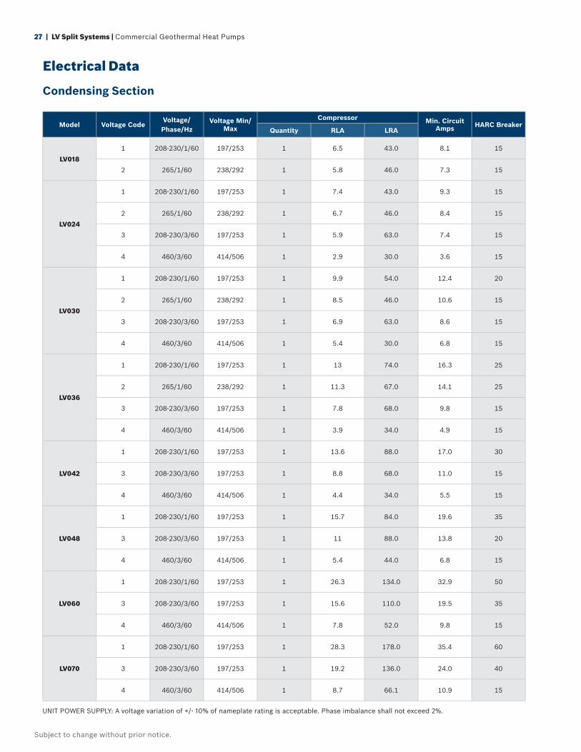
27 | LV Split Systems | Commercial Geothermal Heat Pumps
Subject to change without prior notice.
Electrical Data
Condensing Section
Model Voltage CodeVoltage/ Phase/Hz
Voltage Min/Max
Compressor Min. Circuit Amps HARC Breaker
Quantity RLA LRA
LV018
1 208-230/1/60 197/253 1 6.5 43.0 8.1 15
2 265/1/60 238/292 1 5.8 46.0 7.3 15
LV024
1 208-230/1/60 197/253 1 7.4 43.0 9.3 15
2 265/1/60 238/292 1 6.7 46.0 8.4 15
3 208-230/3/60 197/253 1 5.9 63.0 7.4 15
4 460/3/60 414/506 1 2.9 30.0 3.6 15
LV030
1 208-230/1/60 197/253 1 9.9 54.0 12.4 20
2 265/1/60 238/292 1 8.5 46.0 10.6 15
3 208-230/3/60 197/253 1 6.9 63.0 8.6 15
4 460/3/60 414/506 1 5.4 30.0 6.8 15
LV036
1 208-230/1/60 197/253 1 13 74.0 16.3 25
2 265/1/60 238/292 1 11.3 67.0 14.1 25
3 208-230/3/60 197/253 1 7.8 68.0 9.8 15
4 460/3/60 414/506 1 3.9 34.0 4.9 15
LV042
1 208-230/1/60 197/253 1 13.6 88.0 17.0 30
3 208-230/3/60 197/253 1 8.8 68.0 11.0 15
4 460/3/60 414/506 1 4.4 34.0 5.5 15
LV048
1 208-230/1/60 197/253 1 15.7 84.0 19.6 35
3 208-230/3/60 197/253 1 11 88.0 13.8 20
4 460/3/60 414/506 1 5.4 44.0 6.8 15
LV060
1 208-230/1/60 197/253 1 26.3 134.0 32.9 50
3 208-230/3/60 197/253 1 15.6 110.0 19.5 35
4 460/3/60 414/506 1 7.8 52.0 9.8 15
LV070
1 208-230/1/60 197/253 1 28.3 178.0 35.4 60
3 208-230/3/60 197/253 1 19.2 136.0 24.0 40
4 460/3/60 414/506 1 8.7 66.1 10.9 15
UNIT POWER SUPPLY: A voltage variation of +/- 10% of nameplate rating is acceptable. Phase imbalance shall not exceed 2%.
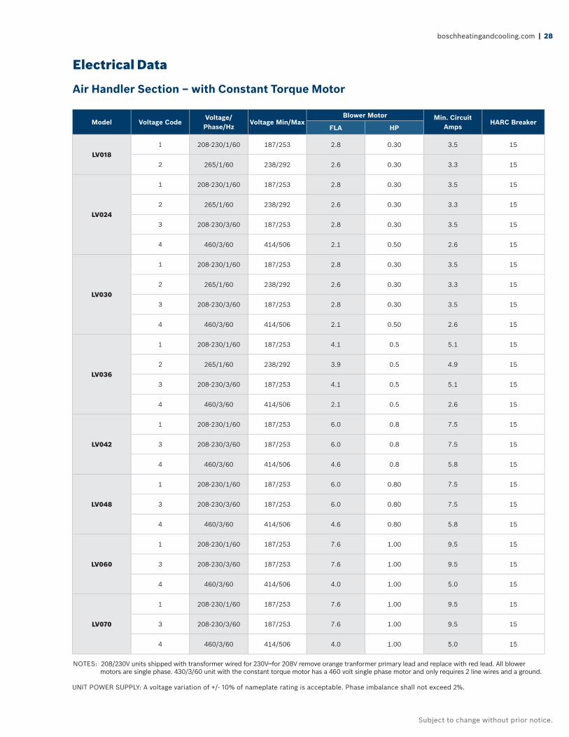
boschheatingandcooling.com | 28
Subject to change without prior notice.
Electrical Data
Air Handler Section – with Constant Torque Motor
Model Voltage CodeVoltage/ Phase/Hz
Voltage Min/MaxBlower Motor Min. Circuit
AmpsHARC Breaker
FLA HP
LV0181 208-230/1/60 187/253 2.8 0.30 3.5 15
2 265/1/60 238/292 2.6 0.30 3.3 15
LV024
1 208-230/1/60 187/253 2.8 0.30 3.5 15
2 265/1/60 238/292 2.6 0.30 3.3 15
3 208-230/3/60 187/253 2.8 0.30 3.5 15
4 460/3/60 414/506 2.1 0.50 2.6 15
LV030
1 208-230/1/60 187/253 2.8 0.30 3.5 15
2 265/1/60 238/292 2.6 0.30 3.3 15
3 208-230/3/60 187/253 2.8 0.30 3.5 15
4 460/3/60 414/506 2.1 0.50 2.6 15
LV036
1 208-230/1/60 187/253 4.1 0.5 5.1 15
2 265/1/60 238/292 3.9 0.5 4.9 15
3 208-230/3/60 187/253 4.1 0.5 5.1 15
4 460/3/60 414/506 2.1 0.5 2.6 15
LV042
1 208-230/1/60 187/253 6.0 0.8 7.5 15
3 208-230/3/60 187/253 6.0 0.8 7.5 15
4 460/3/60 414/506 4.6 0.8 5.8 15
LV048
1 208-230/1/60 187/253 6.0 0.80 7.5 15
3 208-230/3/60 187/253 6.0 0.80 7.5 15
4 460/3/60 414/506 4.6 0.80 5.8 15
LV060
1 208-230/1/60 187/253 7.6 1.00 9.5 15
3 208-230/3/60 187/253 7.6 1.00 9.5 15
4 460/3/60 414/506 4.0 1.00 5.0 15
LV070
1 208-230/1/60 187/253 7.6 1.00 9.5 15
3 208-230/3/60 187/253 7.6 1.00 9.5 15
4 460/3/60 414/506 4.0 1.00 5.0 15
NOTES: 208/230V units shipped with transformer wired for 230V—for 208V remove orange tranformer primary lead and replace with red lead. All blower motors are single phase. 430/3/60 unit with the constant torque motor has a 460 volt single phase motor and only requires 2 line wires and a ground.
UNIT POWER SUPPLY: A voltage variation of +/- 10% of nameplate rating is acceptable. Phase imbalance shall not exceed 2%.
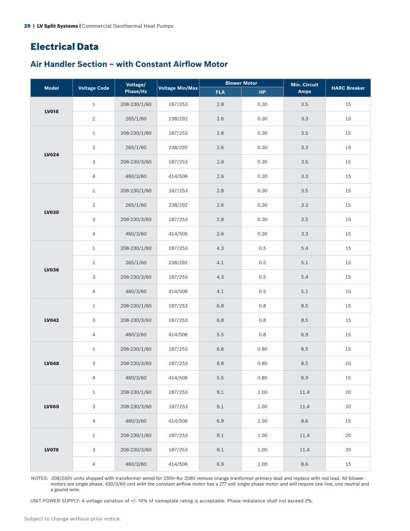
29 | LV Split Systems | Commercial Geothermal Heat Pumps
Subject to change without prior notice.
Electrical Data
Air Handler Section – with Constant Airfl ow Motor
Model Voltage CodeVoltage/ Phase/Hz
Voltage Min/MaxBlower Motor Min. Circuit
AmpsHARC Breaker
FLA HP
LV0181 208-230/1/60 187/253 2.8 0.30 3.5 15
2 265/1/60 238/292 2.6 0.30 3.3 15
LV024
1 208-230/1/60 187/253 2.8 0.30 3.5 15
2 265/1/60 238/292 2.6 0.30 3.3 15
3 208-230/3/60 187/253 2.8 0.30 3.5 15
4 460/3/60 414/506 2.6 0.30 3.3 15
LV030
1 208-230/1/60 187/253 2.8 0.30 3.5 15
2 265/1/60 238/292 2.6 0.30 3.3 15
3 208-230/3/60 187/253 2.8 0.30 3.5 15
4 460/3/60 414/506 2.6 0.30 3.3 15
LV036
1 208-230/1/60 187/253 4.3 0.5 5.4 15
2 265/1/60 238/292 4.1 0.5 5.1 15
3 208-230/3/60 187/253 4.3 0.5 5.4 15
4 460/3/60 414/506 4.1 0.5 5.1 15
LV042
1 208-230/1/60 187/253 6.8 0.8 8.5 15
3 208-230/3/60 187/253 6.8 0.8 8.5 15
4 460/3/60 414/506 5.5 0.8 6.9 15
LV048
1 208-230/1/60 187/253 6.8 0.80 8.5 15
3 208-230/3/60 187/253 6.8 0.80 8.5 15
4 460/3/60 414/506 5.5 0.80 6.9 15
LV060
1 208-230/1/60 187/253 9.1 1.00 11.4 20
3 208-230/3/60 187/253 9.1 1.00 11.4 20
4 460/3/60 414/506 6.9 1.00 8.6 15
LV070
1 208-230/1/60 187/253 9.1 1.00 11.4 20
3 208-230/3/60 187/253 9.1 1.00 11.4 20
4 460/3/60 414/506 6.9 1.00 8.6 15
NOTES: 208/230V units shipped with transformer wired for 230V—for 208V remove orange tranformer primary lead and replace with red lead. All blower motors are single phase. 430/3/60 unit with the constant airfl ow motor has a 277 volt single phase motor and will require one line, one neutral and a gound wire.
UNIT POWER SUPPLY: A voltage variation of +/- 10% of nameplate rating is acceptable. Phase imbalance shall not exceed 2%.
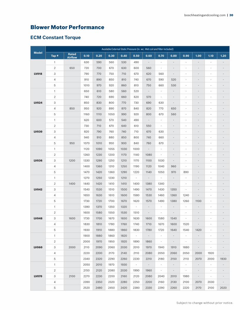
boschheatingandcooling.com | 30
Subject to change without prior notice.
ModelAvailable External Static Pressure (in. wc. Wet coil and fi lter included)
Tap # Rated Airfl ow 0.10 0.20 0.30 0.40 0.50 0.60 0.70 0.80 0.90 1.00 1.10 1.20
LV018
1 630 590 560 530 490 - - - - - - -
2 650 720 700 670 630 600 560 - - - - - -
3 790 770 750 710 670 620 560 - - - - -
4 910 890 850 810 740 670 590 520 - - - -
5 1010 970 920 860 810 750 660 530 - - - -
LV024
1 650 610 580 560 520 - - - - - - -
2 740 720 690 660 620 570 - - - - - -
3 850 830 800 770 730 690 630 - - - - -
4 850 950 920 890 870 840 820 770 650 - - - -
5 1160 1110 1050 990 920 800 670 560 - - - -
LV030
1 620 600 570 540 490 - - - - - - -
2 730 710 670 640 610 550 - - - - - -
3 820 790 760 740 710 670 630 - - - - -
4 940 910 880 850 800 740 660 - - - - -
5 950 1070 1010 950 900 840 760 670 - - - - -
LV036
1 1120 1090 1055 1030 1000 - - - - - - -
2 1260 1230 1200 1170 1140 1080 - - - - - -
3 1200 1330 1290 1250 1210 1170 1100 1030 - - - - -
4 1400 1360 1310 1250 1190 1120 1040 960 - - - -
5 1470 1420 1360 1290 1220 1140 1050 970 890 - - -
LV042
1 1270 1250 1230 1210 - - - - - - - -
2 1400 1440 1420 1410 1410 1400 1380 1340 - - - - -
3 1540 1530 1510 1500 1490 1470 1430 1350 - - - -
4 1650 1630 1610 1600 1580 1530 1460 1360 1240 - - -
5 1730 1720 1700 1670 1620 1570 1490 1380 1260 1100 - -
LV048
1 1390 1370 1350 1320 - - - - - - - -
2 1600 1580 1550 1530 1510 - - - - - - -
3 1600 1730 1700 1670 1650 1630 1600 1580 1540 - - - -
4 1830 1810 1780 1760 1740 1710 1670 1600 1520 - - -
5 1930 1910 1880 1860 1830 1780 1720 1640 1540 1420 - -
LV060
1 1900 1880 1860 1820 - - - - - - - -
2 2000 1970 1950 1920 1890 1860 - - - - - -
3 2000 2110 2090 2060 2030 2010 1970 1940 1910 1880 - - -
4 2220 2200 2170 2140 2110 2080 2050 2060 2050 2000 1920 -
5 2340 2320 2290 2260 2230 2210 2180 2150 2110 2070 2000 1930
LV070
1 2050 2010 1970 1930 - - - - - - - -
2 2150 2120 2080 2030 1990 1960 - - - - - -
3 2100 2270 2230 2200 2160 2120 2080 2040 2010 1980 - - -
4 2390 2350 2320 2280 2250 2200 2160 2130 2100 2070 2030 -
5 2520 2480 2450 2420 2380 2330 2290 2260 2220 2170 2100 2020
Blower Motor Performance
ECM Constant Torque
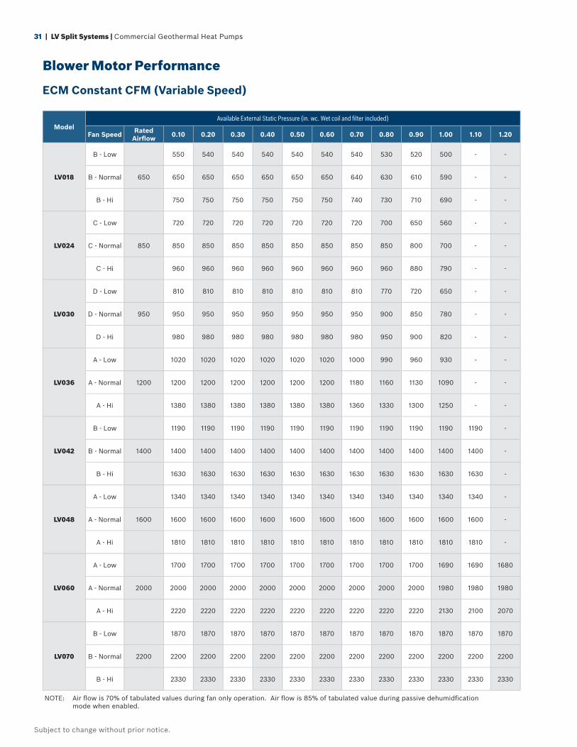
31 | LV Split Systems | Commercial Geothermal Heat Pumps
Subject to change without prior notice.
Blower Motor Performance
ECM Constant CFM (Variable Speed)
ModelAvailable External Static Pressure (in. wc. Wet coil and fi lter included)
Fan Speed Rated Airfl ow 0.10 0.20 0.30 0.40 0.50 0.60 0.70 0.80 0.90 1.00 1.10 1.20
LV018
B - Low 550 540 540 540 540 540 540 530 520 500 - -
B - Normal 650 650 650 650 650 650 650 640 630 610 590 - -
B - Hi 750 750 750 750 750 750 740 730 710 690 - -
LV024
C - Low 720 720 720 720 720 720 720 700 650 560 - -
C - Normal 850 850 850 850 850 850 850 850 850 800 700 - -
C - Hi 960 960 960 960 960 960 960 960 880 790 - -
LV030
D - Low 810 810 810 810 810 810 810 770 720 650 - -
D - Normal 950 950 950 950 950 950 950 950 900 850 780 - -
D - Hi 980 980 980 980 980 980 980 950 900 820 - -
LV036
A - Low 1020 1020 1020 1020 1020 1020 1000 990 960 930 - -
A - Normal 1200 1200 1200 1200 1200 1200 1200 1180 1160 1130 1090 - -
A - Hi 1380 1380 1380 1380 1380 1380 1360 1330 1300 1250 - -
LV042
B - Low 1190 1190 1190 1190 1190 1190 1190 1190 1190 1190 1190 -
B - Normal 1400 1400 1400 1400 1400 1400 1400 1400 1400 1400 1400 1400 -
B - Hi 1630 1630 1630 1630 1630 1630 1630 1630 1630 1630 1630 -
LV048
A - Low 1340 1340 1340 1340 1340 1340 1340 1340 1340 1340 1340 -
A - Normal 1600 1600 1600 1600 1600 1600 1600 1600 1600 1600 1600 1600 -
A - Hi 1810 1810 1810 1810 1810 1810 1810 1810 1810 1810 1810 -
LV060
A - Low 1700 1700 1700 1700 1700 1700 1700 1700 1700 1690 1690 1680
A - Normal 2000 2000 2000 2000 2000 2000 2000 2000 2000 2000 1980 1980 1980
A - Hi 2220 2220 2220 2220 2220 2220 2220 2220 2220 2130 2100 2070
LV070
B - Low 1870 1870 1870 1870 1870 1870 1870 1870 1870 1870 1870 1870
B - Normal 2200 2200 2200 2200 2200 2200 2200 2200 2200 2200 2200 2200 2200
B - Hi 2330 2330 2330 2330 2330 2330 2330 2330 2330 2330 2330 2330
NOTE: Air fl ow is 70% of tabulated values during fan only operation. Air fl ow is 85% of tabulated value during passive dehumidfi cation mode when enabled.
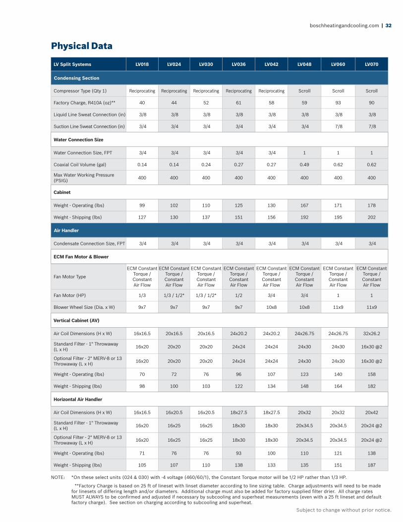
boschheatingandcooling.com | 32
Subject to change without prior notice.
Physical Data
NOTE: *On these select units (024 & 030) with -4 voltage (460/60/1), the Constant Torque motor will be 1/2 HP rather than 1/3 HP.
**Factory Charge is based on 25 ft of lineset with linset diameter according to line sizing table. Charge adjustments will need to be made for linesets of differing length and/or diameters. Additional charge must also be added for factory supplied fi lter drier. All charge rates MUST ALWAYS to be confi rmed and adjusted if necessary by subcooling and superheat measurements (even with a 25 ft lineset and default factory charge). See section on charging according to subcooling and superheat.
LV Split Systems LV018 LV024 LV030 LV036 LV042 LV048 LV060 LV070
Condensing Section
Compressor Type (Qty 1) Reciprocating Reciprocating Reciprocating Reciprocating Reciprocating Scroll Scroll Scroll
Factory Charge, R410A (oz)** 40 44 52 61 58 59 93 90
Liquid Line Sweat Connection (in) 3/8 3/8 3/8 3/8 3/8 3/8 3/8 3/8
Suction Line Sweat Connection (in) 3/4 3/4 3/4 3/4 3/4 3/4 7/8 7/8
Water Connection Size
Water Connection Size, FPT 3/4 3/4 3/4 3/4 3/4 1 1 1
Coaxial Coil Volume (gal) 0.14 0.14 0.24 0.27 0.27 0.49 0.62 0.62
Max Water Working Pressure (PSIG) 400 400 400 400 400 400 400 400
Cabinet
Weight - Operating (lbs) 99 102 110 125 130 167 171 178
Weight - Shipping (lbs) 127 130 137 151 156 192 195 202
Air Handler
Condensate Connection Size, FPT 3/4 3/4 3/4 3/4 3/4 3/4 3/4 3/4
ECM Fan Motor & Blower
Fan Motor Type
ECM Constant Torque / Constant Air Flow
ECM Constant Torque / Constant Air Flow
ECM Constant Torque / Constant Air Flow
ECM Constant Torque / Constant Air Flow
ECM Constant Torque / Constant Air Flow
ECM Constant Torque / Constant Air Flow
ECM Constant Torque / Constant Air Flow
ECM Constant Torque / Constant Air Flow
Fan Motor (HP) 1/3 1/3 / 1/2* 1/3 / 1/2* 1/2 3/4 3/4 1 1
Blower Wheel Size (Dia. x W) 9x7 9x7 9x7 9x7 10x8 10x8 11x9 11x9
Vertical Cabinet (AV)
Air Coil Dimensions (H x W) 16x16.5 20x16.5 20x16.5 24x20.2 24x20.2 24x26.75 24x26.75 32x26.2
Standard Filter - 1" Throwaway (L x H) 16x20 20x20 20x20 24x24 24x24 24x30 24x30 16x30 @2
Optional Filter - 2" MERV-8 or 13 Throwaway (L x H) 16x20 20x20 20x20 24x24 24x24 24x30 24x30 16x30 @2
Weight - Operating (lbs) 70 72 76 96 107 123 140 158
Weight - Shipping (lbs) 98 100 103 122 134 148 164 182
Horizontal Air Handler
Air Coil Dimensions (H x W) 16x16.5 16x20.5 16x20.5 18x27.5 18x27.5 20x32 20x32 20x42
Standard Filter - 1" Throwaway (L x H) 16x20 16x25 16x25 18x30 18x30 20x34.5 20x34.5 20x24 @2
Optional Filter - 2" MERV-8 or 13 Throwaway (L x H) 16x20 16x25 16x25 18x30 18x30 20x34.5 20x34.5 20x24 @2
Weight - Operating (lbs) 71 76 76 93 100 110 121 138
Weight - Shipping (lbs) 105 107 110 138 133 135 151 187
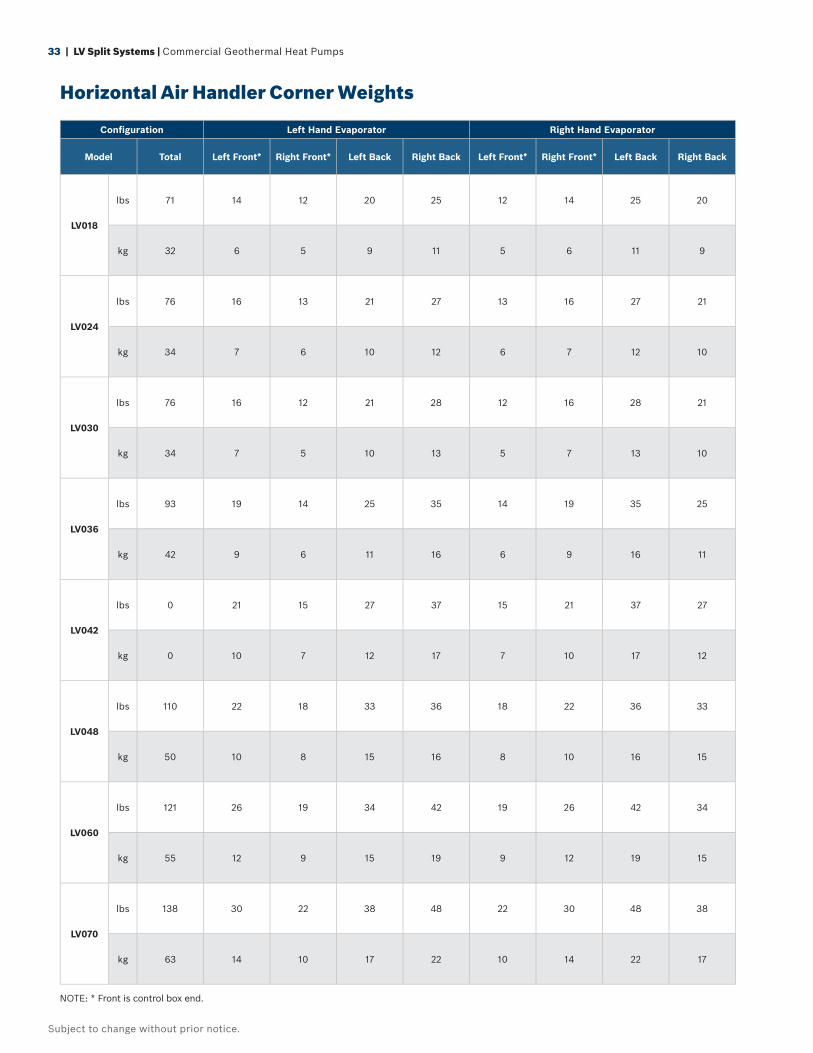
33 | LV Split Systems | Commercial Geothermal Heat Pumps
Subject to change without prior notice.
Confi guration Left Hand Evaporator Right Hand Evaporator
Model Total Left Front* Right Front* Left Back Right Back Left Front* Right Front* Left Back Right Back
LV018
lbs 71 14 12 20 25 12 14 25 20
kg 32 6 5 9 11 5 6 11 9
LV024
lbs 76 16 13 21 27 13 16 27 21
kg 34 7 6 10 12 6 7 12 10
LV030
lbs 76 16 12 21 28 12 16 28 21
kg 34 7 5 10 13 5 7 13 10
LV036
lbs 93 19 14 25 35 14 19 35 25
kg 42 9 6 11 16 6 9 16 11
LV042
lbs 0 21 15 27 37 15 21 37 27
kg 0 10 7 12 17 7 10 17 12
LV048
lbs 110 22 18 33 36 18 22 36 33
kg 50 10 8 15 16 8 10 16 15
LV060
lbs 121 26 19 34 42 19 26 42 34
kg 55 12 9 15 19 9 12 19 15
LV070
lbs 138 30 22 38 48 22 30 48 38
kg 63 14 10 17 22 10 14 22 17
NOTE: * Front is control box end.
Horizontal Air Handler Corner Weights
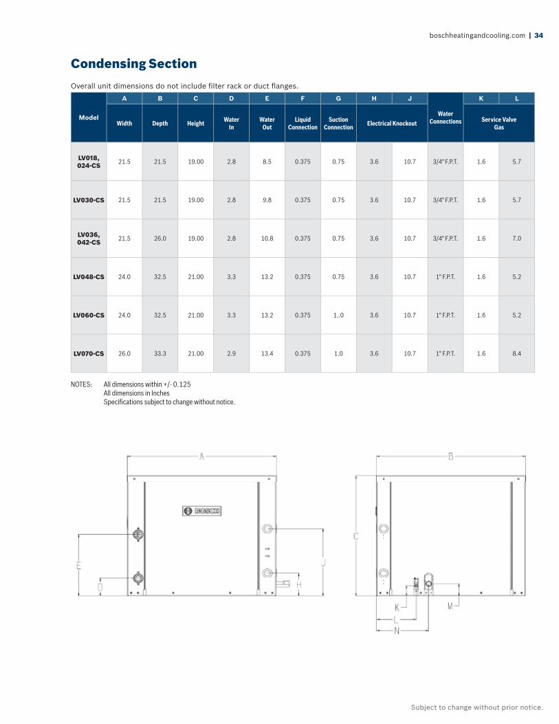
boschheatingandcooling.com | 34
Subject to change without prior notice.
Model
A B C D E F G H J
Water Connections
K L
Width Depth Height Water In
Water Out
Liquid Connection
Suction Connection Electrical Knockout Service Valve
Gas
LV018, 024-CS 21.5 21.5 19.00 2.8 8.5 0.375 0.75 3.6 10.7 3/4" F.P.T. 1.6 5.7
LV030-CS 21.5 21.5 19.00 2.8 9.8 0.375 0.75 3.6 10.7 3/4" F.P.T. 1.6 5.7
LV036, 042-CS 21.5 26.0 19.00 2.8 10.8 0.375 0.75 3.6 10.7 3/4" F.P.T. 1.6 7.0
LV048-CS 24.0 32.5 21.00 3.3 13.2 0.375 0.75 3.6 10.7 1" F.P.T. 1.6 5.2
LV060-CS 24.0 32.5 21.00 3.3 13.2 0.375 1..0 3.6 10.7 1" F.P.T. 1.6 5.2
LV070-CS 26.0 33.3 21.00 2.9 13.4 0.375 1.0 3.6 10.7 1" F.P.T. 1.6 8.4
Overall unit dimensions do not include fi lter rack or duct fl anges.
NOTES: All dimensions within +/- 0.125 All dimensions in Inches Specifi cations subject to change without notice.
Condensing Section
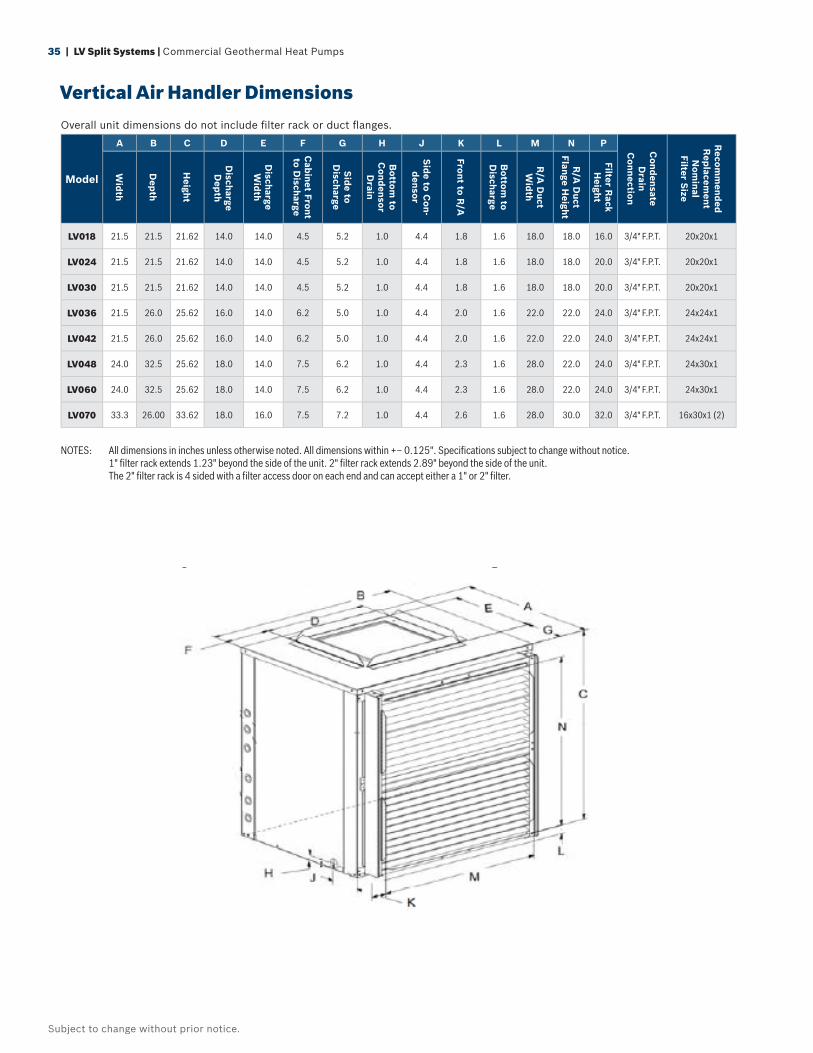
35 | LV Split Systems | Commercial Geothermal Heat Pumps
Subject to change without prior notice.
Vertical Air Handler Dimensions
Model
A B C D E F G H J K L M N P Cond
ensate D
rainC
onnection
Recom
mend
edR
eplacem
entN
ominal
Filter Size
Wid
th
Dep
th
Height
Discharge D
epth
Discharge W
idth
Cab
inet Front to D
ischarge
Sid
e to D
ischarge
Bottom
to C
ondensor
Drain
Sid
e to Con-
densor
Front to R/A
Bottom
to D
ischarge
R/A
Duct
Wid
th
R/A
Duct
Flange Height
Filter Rack
Height
LV018 21.5 21.5 21.62 14.0 14.0 4.5 5.2 1.0 4.4 1.8 1.6 18.0 18.0 16.0 3/4" F.P.T. 20x20x1
LV024 21.5 21.5 21.62 14.0 14.0 4.5 5.2 1.0 4.4 1.8 1.6 18.0 18.0 20.0 3/4" F.P.T. 20x20x1
LV030 21.5 21.5 21.62 14.0 14.0 4.5 5.2 1.0 4.4 1.8 1.6 18.0 18.0 20.0 3/4" F.P.T. 20x20x1
LV036 21.5 26.0 25.62 16.0 14.0 6.2 5.0 1.0 4.4 2.0 1.6 22.0 22.0 24.0 3/4" F.P.T. 24x24x1
LV042 21.5 26.0 25.62 16.0 14.0 6.2 5.0 1.0 4.4 2.0 1.6 22.0 22.0 24.0 3/4" F.P.T. 24x24x1
LV048 24.0 32.5 25.62 18.0 14.0 7.5 6.2 1.0 4.4 2.3 1.6 28.0 22.0 24.0 3/4" F.P.T. 24x30x1
LV060 24.0 32.5 25.62 18.0 14.0 7.5 6.2 1.0 4.4 2.3 1.6 28.0 22.0 24.0 3/4" F.P.T. 24x30x1
LV070 33.3 26.00 33.62 18.0 16.0 7.5 7.2 1.0 4.4 2.6 1.6 28.0 30.0 32.0 3/4" F.P.T. 16x30x1 (2)
Overall unit dimensions do not include fi lter rack or duct fl anges.
NOTES: All dimensions in inches unless otherwise noted. All dimensions within +– 0.125". Specifi cations subject to change without notice. 1" fi lter rack extends 1.23" beyond the side of the unit. 2" fi lter rack extends 2.89" beyond the side of the unit. The 2" fi lter rack is 4 sided with a fi lter access door on each end and can accept either a 1" or 2" fi lter.
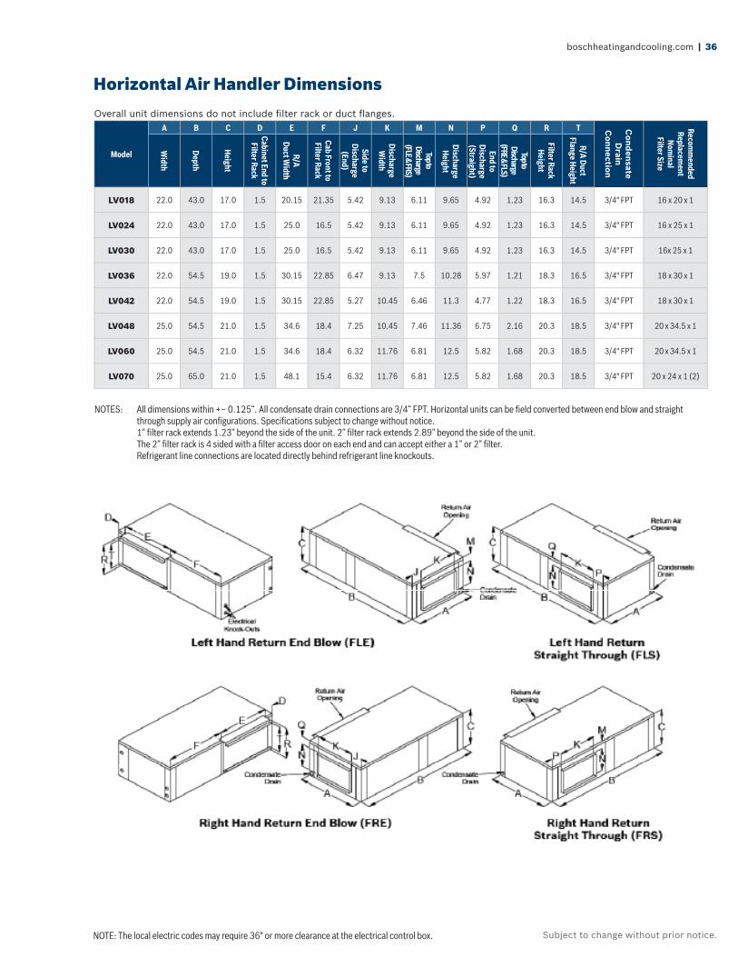
boschheatingandcooling.com | 36
Subject to change without prior notice.
Model
A B C D E F J K M N P Q R T Cond
ensate D
rainC
onnection
Recomm
endedReplacem
entNom
inalFilter Size
Width
Depth
Height
Cabinet End to Filter Rack
R/ADuct W
idth
Cab Front to Filter Rack
Side to Discharge
(End)
Discharge W
idth
Top to Discharge
(FLE & FRS)
Discharge Height
End to Discharge (Straight)
Top to Discharge
(FRE & FLS)
Filter Rack Height
R/A DuctFlange Height
LV018 22.0 43.0 17.0 1.5 20.15 21.35 5.42 9.13 6.11 9.65 4.92 1.23 16.3 14.5 3/4" FPT 16 x 20 x 1
LV024 22.0 43.0 17.0 1.5 25.0 16.5 5.42 9.13 6.11 9.65 4.92 1.23 16.3 14.5 3/4" FPT 16 x 25 x 1
LV030 22.0 43.0 17.0 1.5 25.0 16.5 5.42 9.13 6.11 9.65 4.92 1.23 16.3 14.5 3/4" FPT 16x 25 x 1
LV036 22.0 54.5 19.0 1.5 30.15 22.85 6.47 9.13 7.5 10.28 5.97 1.21 18.3 16.5 3/4" FPT 18 x 30 x 1
LV042 22.0 54.5 19.0 1.5 30.15 22.85 5.27 10.45 6.46 11.3 4.77 1.22 18.3 16.5 3/4" FPT 18 x 30 x 1
LV048 25.0 54.5 21.0 1.5 34.6 18.4 7.25 10.45 7.46 11.36 6.75 2.16 20.3 18.5 3/4" FPT 20 x 34.5 x 1
LV060 25.0 54.5 21.0 1.5 34.6 18.4 6.32 11.76 6.81 12.5 5.82 1.68 20.3 18.5 3/4" FPT 20 x 34.5 x 1
LV070 25.0 65.0 21.0 1.5 48.1 15.4 6.32 11.76 6.81 12.5 5.82 1.68 20.3 18.5 3/4" FPT 20 x 24 x 1 (2)
NOTES: All dimensions within +– 0.125“. All condensate drain connections are 3/4“ FPT. Horizontal units can be fi eld converted between end blow and straight through supply air confi gurations. Specifi cations subject to change without notice.
1“ fi lter rack extends 1.23“ beyond the side of the unit. 2“ fi lter rack extends 2.89“ beyond the side of the unit. The 2“ fi lter rack is 4 sided with a fi lter access door on each end and can accept either a 1“ or 2“ fi lter.
Refrigerant line connections are located directly behind refrigerant line knockouts.
Overall unit dimensions do not include fi lter rack or duct fl anges.
NOTE: The local electric codes may require 36" or more clearance at the electrical control box.
Horizontal Air Handler Dimensions
37 | LV Split Systems | Commercial Geothermal Heat Pumps
Subject to change without prior notice.
General
Furnish and install FHP water source heat pumps as indicated on the plans with capacities and characteristics as listed in the schedule and the specifi cations that follow. The units shall be manufactured in an ISO 9001:2000 certifi ed facility.
Split System Water Source Heat Pumps
With the factory installed extended range package, units shall operate with entering fl uid temperatures between 50˚F (10˚C) and 110˚F (43.3˚C) in cooling and between 25˚F (-3.9˚C) and 80˚F (27˚C) in heating. Equivalent units from other manufacturers can be proposed, provided approval to bid is given 10 days prior to bid closing. All equipment with a nominal capacity of 135,000 BTUH Total Cooling or lower must be listed in the current AHRI Applied Equipment Directory under the AHRI Standard AHRI/ISO- 13256-1, WLHP, GWHP and GLHP certifi cation points.
All equipment in this section must meet or exceed the DOE mandated minimum EER’s and COP’s as listed in ASHRAE 90.1 as follows:
For the AHRI/ISO-13256-1, WLHP Rating (12.0 EER and 4.2 COP for units larger than a nominal 17,000 BTUH Total Cooling – 11.2 EER and 4.2 COP for units below a nominal 17,000 BTUH Total Cooling).
For the AHRI/ISO-13256-1, GLHP Rating a minimum 13.4 EER and 3.1 COP. All units shall be listed with Underwriters Laboratories (UL) for safety.
Standard Construction
Units shall have the air fl ow arrangement as shown on the plans. If units with these arrangements are not used, the contractor supplying the water source heat pumps is responsible for any extra costs incurred by other trades and must submit detailed mechanical drawings showing ductwork requirements and changes or relocation of any other mechanical or electrical system. If other arrangements make servicing diffi cult, the contractor must provide access panels and clear routes to ease service. The architect must approve all changes 10 days prior to bid.
All units shall have stainless steel drain pans to comply with this project’s IAQ requirements. Painted steel or plastic is not acceptable.
The cabinet shall be fabricated from heavy-gauge galvanized steel for superior corrosion protection. All interior surfaces shall be lined with a minimum of 1/2 inch (12.7mm) thick, multi density, coated, glass fi ber insulation. Insulation within the air handling section shall not have any exposed edges. All insulation must meet NFPA 9®0A and be certifi ed to meet the GREENGUARD Indoor Air Quality Standard for Low Emitting Products. One blower access panel and two compressor compartment access panels shall be removable with supply and return air ductwork in place.
Unit shall have a fl oating compressor or pan consisting of a 1/2” (12 mm) thick high density elastomeric pad between the compressor base plate and the unit base pan to prevent transmission of vibration to the structure.
Units shall have a 1” thick throwaway type glass fi ber fi lter as standard.
Units shall have an optional 2” thick pleated MERV-8 and MERV-13 available.
The fi lter rack shall incorporate a 1 inch duct fl ange.
Cabinets shall have separate holes and knockouts for entrance of line voltage and low voltage control wiring.
Supply and return water connections shall be brass female pipe thread fi ttings and mounted fl ush to cabinet exterior. Connections that require a back up wrench or that extrude past the unit corner post are not acceptable. Condensate connections will be stainless steel female pipe thread fi ttings. Plastic is not acceptable.
Hanging brackets shall be provided as standard for horizontal units.
Fan and Motor Assembly
The fan shall be direct-drive centrifugal forward curved type with a dynamically balanced wheel. The housing and wheel shall be designed for quiet low velocity operation.
Guide Specifi cations
boschheatingandcooling.com | 38
Subject to change without prior notice.
Guide Specifi cations
The blower housing shall feature a removable inlet ring to facilitate removal and servicing of the fan motor.
Models shall have an constant torque electronically commutated motor (ECM) for premium fan effi ciency. These motors shall feature 5 pre-programmed torque settings that can be changed in the fi eld to match design requirements. 460 V – 3 Ph – 60 Hz units with these motors must be able to operate without the need for a neutral wire for the motor.
Models shall have an optional constant CFM electronically commutated motor for premium fan effi ciency and constant air delivery over a wide range of external static pressures. These motors shall be fi eld adjustable for +/- 15% of nominal design air fl ow. These motors shall provide feedback to the unit control box to verify motor operating mode and the delivered CFM.
Refrigerant Circuit
Units shall use R-410A refrigerant. All units shall have a factory sealed and fully charged refrigerant circuit with the following components:
Hermetic compressor: Hermetic reciprocating, or scroll compressors shall be specifi cally designed for R-410A refrigerant and shall be internally sprung (if reciprocating), externally isolated and with thermal overload protection.
A refrigerant metering thermal expansion valve (TXV) with internal checking shall be provided in the air handler and in the condensing section.
The fi nned tube heat exchanger shall be constructed of lanced aluminum fi ns not exceeding sixteen fi ns per inch bonded to rifl ed copper tubes in a staggered pattern and will have a 600 PSIG (4140 kPa) working pressure. The heat exchanger shall have aluminum end sheets.
Optional Air Coil Protection: The fi nned tube heat exchanger shall have optional Duo-GuardTM protective coil coating. This corrosion protection shall consist of tin plated copper tubing with coated aluminum fi ns that must pass 1000 hours of ASTM B117 salt fog testing. Painted, dipped or e-coated heat exchangers are not acceptable.
Reversing valve. Reversing valves shall be four-way solenoid activated refrigerant valves which shall fail to the heating operation should the solenoid fail to
function. Reversing valves which fail to the cooling operation shall not be allowed.
Coaxial (tube in tube) refrigerant to water heat exchanger. Refrigerant to water heat exchangers shall be of copper inner water tube and steel outer refrigerant tube design rated to withstand 600 PSIG working refrigerant pressure and 400 PSIG working water pressure. Shell and Tube style refrigerant to water heat exchangers shall be treated as pressure vessels and shall require refrigerant pressure relief valves piped to the exterior of the building. The contractor supplying the water source heat pumps with Shell and Tube heat exchangers shall be responsible for any additional installation costs. Brazed Plate water to refrigerant heat exchangers shall require additional centrifugal separators added to the supply water piping at each unit. Each separator shall have an automated clean out valve piped to a waste line. The contractor supplying water source heat pumps with Brazed Plate heat exchangers shall be responsible for any additional costs.
Option for Cupro-Nickel water coil – The refrigerant to water heat exchanger shall be of cupro-nickel inner water tube construction.
Safety controls include both a high pressure and low pressure switch. Temperature sensors shall not replace these safety switches. See the controls section of this specifi cation for additional information.
Access fi ttings shall be factory installed on high and low pressure refrigerant lines to facilitate fi eld service.
Activation of any safety device shall prevent compressor operation via a lockout circuit. The lockout circuit shall be reset at the thermostat or at the contractor supplied disconnect switch. Units which may be reset at the disconnect switch only shall not be acceptable. Refer to solid state safety circuit below.
Electrical
Controls and safety devices will be factory wired and mounted within the unit. Controls shall include fan relay, compressor contactor, 24V transformer, reversing valve coil solid state lockout controller and Unit Protection Module (UPM). The standard transformer shall be rated for a minimum 50 VA. All units shall be name-plated for use with time delay fuses or HACR circuit breakers. Unit controls shall be 24 volts.
39 | LV Split Systems | Commercial Geothermal Heat Pumps
Subject to change without prior notice.
Option: Optional transformers shall be rated 75VA or 100VA and shall have a push button reset circuit breaker on the secondary power.
Solid-State Safety Circuit
All units shall have a solid-state UPM safety control circuit with the following features:
Anti-short cycle time delay (5 minute delay on break).
Random start time delay on initial power.
Brown out/surge/power interruption protection.
120 second low pressure switch bypass timer.
High refrigerant pressure shutdown.
Low refrigerant pressure shutdown.
Low water temperature shutdown (adjustable for closed loop systems).
24 VAC alarm output for remote fault indication.
The UPM shall automatically reset after a safety shut down. Restart the unit if the cause of the shut down no longer exists (except for low temperature shutdowns). Should a fault re-occur within 60 minutes after resest, then a “hard” lockout will occur. A light emitting diode (LED) shall annunciate the following alarms: brown out, high refrigerant pressure, low refrigerant pressure and low water temperature. The condensate overfl ow sensor is not included as standard and will be a fi eld installed accessory item. The LED will display each fault condition as soon as the fault occurs. If a hard lockout occurs, then the fault LED will display the type of fault until the unit is reset.
The UPM shall feature the following fi eld confi gurable adjustments:
Lock out reset on thermostat interruption or power reset.
2 or 4 restart attempts before a hard lockout.
Test mode (reduces all time delays to 5 seconds for diagnostic work).
Antifreeze setting for low water temperature sensor.
Safety devices include:
Low pressure cutout set a 40 PSIG (280 kPa) for loss of charge protection (freezestat and/or high discharge gas temperature sensor is not acceptable).
High pressure cutout control set at 600 PSIG(4125 Kpa).
Low supply water temperature sensor that detects drops in refrigerant temperature that could result in water coax heat exchanger freezing.
On board voltage detection that disables the compressor control circuit if there are extreme variations in supply voltage.
An optional energy management relay that allows unit control by an external source shall be factory installed. A terminal block with screw terminals shall be provided for control wiring.
Additional Options
Units shall have an optional 2-way electrically operated shut-off valve mounted internally in the unit cabinet.
Units shall have an optional water fl ow regulating valve set to 3 gallons per minute of water fl ow per nominal ton of refrigeration capacity.
Compressor blanket is optional for all LV Split units.
Water Differential Pressure Switch: Prevents unit operation if there is no fl uid fl ow. This factory installed, internally mounted device shall be rated at 600 PSI and disable the compressor if a lack of waterfl ow occurs.
Factory-installed control options: Water differential pressure switch, 75 VA and 100 VA transformer (resettable), phase loss and reversal protection, and unit mounted disconnect switch.
A 2”, four-sided fi lter rack is optional to accommodate nominal 2” thick pleated fi lters.
Hose Kits
All units shall be connected with hoses. The hoses shall be either 2 or 3 feet long, braided stainless steel, fi re rated hoses complete with adapters. Non-fi re rated hoses are not acceptable. optional ball valves with P/T ports, fl ow controller, Y strainer and electric valve shall be in included as specifi ed in the schedule.
Guide Specifi cations
boschheatingandcooling.com | 40
Subject to change without prior notice.
Notes
41 | LV Split Systems | Commercial Geothermal Heat Pumps
Subject to change without prior notice.
Notes

boschheatingandcooling.com | 42
Subject to change without prior notice.
Notes
Subject to change without prior notice.
®
Bosch Thermotechnology Corp.555 N.W. 65th Court, Fort Lauderdale, FL 33309Phone: 954-776-5471 | Fax: 954-776-5529www.boschheatingandcooling.com
BTC 760304302 C | 10.2016Copyright © 2014 Bosch Thermotechnology Corp. All rights reserved. Subject to change without notice.