low-power task scheduling algorithm for large-scale cloud data centers
TRANSCRIPT
Journal of Systems Engineering and Electronics
Vol. 24, No. 5, October 2013, pp.870–878
Low-power task scheduling algorithm forlarge-scale cloud data centers
Xiaolong Xu1,2,*, Jiaxing Wu1, Geng Yang3, and Ruchuan Wang1
1. College of Computer, Nanjing University of Posts and Telecommunications, Nanjing 210003, China;2. State Key Laboratory for Novel Software Technology, Nanjing University, Nanjing 210046, China;
3. Key Lab of Broadband Wireless Communication and Sensor Network Technology of Ministry of Education,Nanjing University of Posts and Telecommunications, Nanjing 210003, China
Abstract: How to effectively reduce the energy consumption oflarge-scale data centers is a key issue in cloud computing. This pa-per presents a novel low-power task scheduling algorithm (LTSA)for large-scale cloud data centers. The winner tree is introducedto make the data nodes as the leaf nodes of the tree and thefinal winner on the purpose of reducing energy consumption isselected. The complexity of large-scale cloud data centers is fullyconsider, and the task comparson coefficient is defined to maketask scheduling strategy more reasonable. Experiments and per-formance analysis show that the proposed algorithm can effec-tively improve the node utilization, and reduce the overall powerconsumption of the cloud data center.
Keywords: cloud computing, data center, task scheduling, energyconsumption.
DOI: 10.1109/JSEE.2013.00101
1. Introduction
As the large-scale cloud computing infrastructure, thecloud data center gets into a high-speed developmentphase. However, the high energy consumption of clouddata centers is becoming a difficult issue around the worldin general. The investigation of the United States Envi-ronmental Protection Agency showed that the amount ofpower consumed by the information technology (IT) in-frastructure accounted for 1.5% of the total power con-sumption in the United States in 2006, and will increase
Manuscript received November 03, 2012.*Corresponding author.This work was supported by the National Natural Science Foun-
dation of China (61202004; 61272084), the National Key Basic Re-search Program of China (973 Program) (2011CB302903), the Spe-cialized Research Fund for the Doctoral Program of Higher Education(20093223120001; 20113223110003), the China Postdoctoral ScienceFoundation Funded Project (2011M500095; 2012T50514), the NaturalScience Foundation of Jiangsu Province (BK2011754; BK2009426), theJiangsu Postdoctoral Science Foundation Funded Project (1102103C),the Natural Science Fund of Higher Education of Jiangsu Province(12KJB520007), and the Project Funded by the Priority Academic Pro-gram Development of Jiangsu Higher Education Institutions (yx002001).
to six times in 2014 [1]. The research report of Interna-tional Data Corporation (IDC) showed that the energy con-sumption brought about by large-scale data centers has in-creased by 400% in the past 30 years, and is still growingrapidly [2]. In the life cycle of a data center, the cost of itsenergy has exceeded the cost of hardware, and become thesecond largest after the cost of human resources [3]. Howto control and reduce energy consumption has become oneof the key issues needed to be solved as soon as possible.
In order to maintain the quality of service (QoS), clouddata centers need mostly to build and configure high-performance server cluster according to the highest pos-sible workload. This strategy makes the rate of server uti-lization be generally less than 30% [4], which is one of themain reasons leading to energy waste.
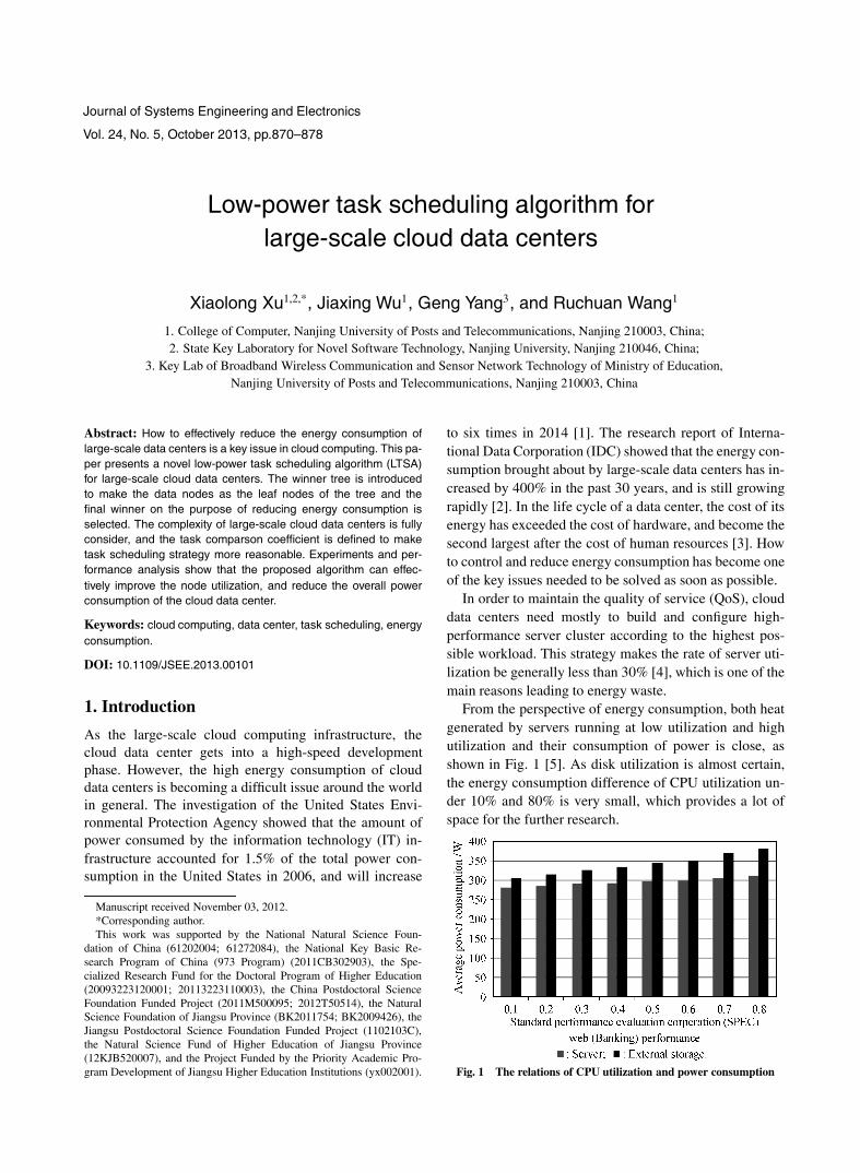
From the perspective of energy consumption, both heatgenerated by servers running at low utilization and highutilization and their consumption of power is close, asshown in Fig. 1 [5]. As disk utilization is almost certain,the energy consumption difference of CPU utilization un-der 10% and 80% is very small, which provides a lot ofspace for the further research.
Fig. 1 The relations of CPU utilization and power consumption
Xiaolong Xu et al.: Low-power task scheduling algorithm for large-scale cloud data centers 871
The current typical approaches of reducing data centerenergy consumption can be divided into the following ca-tegories:
(i) Energy-saving technology of the data centre subsys-tem [6–9]. Its core idea is to adjust the node subsystemstate, such as the CPU dynamic voltage technology andhard driver transmission technology, in order to optimizethe state of each node in a data center, and to reduce energyconsumption. However, this partial optimization approachis unable to satisfy the overall optimization requirement ofthe entire cloud data center.
(ii) Power limitation technology [10,11]. Its core idea isto set the upper limit of power consumption to realise therational allocation of data center power resources, and toavoid the unnecessary supply of energy. At the same time,the saved electricity is able to be redeployed to those addeddata center equipment, so as to guarantee the QoS of datacenter. However, the maintenance of new equipment andthe spending on human resource increase the additionalcosts of data center.
(iii) Virtualization technology [12–14]. Its core idea isvirtualizing cluster servers into the resource pool, whichhas been already adopted by current cloud systems, andcan implement multiple tasks running in different virtualmachines based on the same node, thereby improving theutilization of computer resources and reducing energy con-sumption. However, the virtual computing (especially thedeep-level virtualization) often leads to high-performancecosts, because the virtualization technology sets layer-by-layer virtualizations from underlying hardware to applica-tions, and each virtual layer results in some loss of effec-tiveness.
(iv) Server integration [15–17]. It is the most popular so-lution to reduce energy consumption. Its core idea is to dis-tinguish the IT resources in accordance with a certain orderto make limited resources allocated to the mission with thelowest energy consumption. Its advantages are simplifyingmanagement, increasing efficiency, improving the utiliza-tion of servers, reducing the costs of hardware acquisition,and saving energy. However, the current integration strat-egy just limits to small-scale data centers, not fully takinginto account the complexity of the large-scale cloud datacenter.
In general, the data center’s low-power schedulingstrategies are based on the following two objectives:
(i) Matching the number of working nodes with thenumber of tasks, in order to let the rest of the nodes workat the energy-saving mode;
(ii) Making storage and computing power of each nodematch the workload assigned by the node, so as to avoidthe low utilization rate of resources and energy.
Srikantaiah et al. [15] proved that there is an optimal re-source allocation value in a certain cloud data center, mak-ing the lowest energy consumption per operation. Basedon the optimal resource allocation value, the whole pro-cess is abstracted as a two-dimensional packing process:filling each box with least number of boxes as far as pos-sible. This method can reduce the energy consumption tosome extent. However there are still three problems neededto be solved:
(i) Not giving full consideration to the scale of the clouddata center. With the scale of the cloud data center in-creasing, the time spended in selecting appropriate nodesfor task execution will grow exponentially. Because of thehuge number of nodes in cloud data center, this kind of al-gorithms cannot always provide right results within a rea-sonable time.
(ii) Not giving full consideration to the operating statediversity of nodes in the cloud data center. The currentalgorithms usually do not differentiate nodes in differentstates when they allocate tasks, leading to the unnecessaryactivation of a large number of dormant nodes and extraenergy waste.
(iii) Not giving full consideration to the complexity oftasks accepted by the cloud data center. As an open plat-form, the cloud data center may carry on a large variety ofdifferent tasks at the same time. The current algorithms aregenerally not able to provide suitable mechanisms to dis-tinguish different tasks effectively, but choose the simplefirst come first serve (FCFS) strategy, which is obviouslylack of rationality.
This paper puts forward a low-power task schedulingalgorithm (LTSA) for large-scale cloud data centers basedon the winner tree, which fully considers the complexityof the large-scale cloud data center, and defines the taskcomparison coefficient to make task scheduling more rea-sonable while the cloud data center handles multiple tasksat the same time.
2. System model
In order to effectively design and deploy an LTSA forlarge-scale cloud data centers, we first build node modeland task model. The values of node model and task modelare used to abstract complex cloud environment effec-tively, which can not only reflect the actual situation of acloud data center during its task scheduling, but also effec-tively shield other confounding factors.
2.1 Node model
Nodes of the cloud data center can be divided into two cate-gories based on their functions: master nodes and datanodes. When a user submits a piece of task to the cloud
872 Journal of Systems Engineering and Electronics Vol. 24, No. 5, October 2013
system, a master node is responsible to select appropriatedata nodes to execute the task after it divides into severalsub-tasks. When all sub-tasks of the task are accomplished,the master node will return the final result to the user.
Definition 1 Master node is only one in the logical andresponsible for the management of the entire cloud system.
Definition 2 Data node can be abstracted as the follo-wing model:
DN = (ID, CPU, DIO, State) (1)
where DN.ID identifies a data node uniquely; DN.CPU
means the current CPU utilization rate of data node;DN.DIO means the disk transmission rate of data node;both DN.CPU and DN.DIO indicate the computing re-sources of data node which has been used.
As the core component of computer, CPU plays an ir-replaceable role during the whole processing of tasks. Theperformance and energy consumption of CPU make a pro-found impact on a range of other devices’ energy con-sumption, such as fan. That is why DN.CPU becomesthe primary consideration of this paper. The disk trans-mission rate is currently the bottleneck of the computerperformance. On the one hand, the I/O performance ofthe traditional mechanical harddisk has not been improvedas fast as CPU, while the new solid state disk (SSD) hasnot been widely deployed in cloud data center yet. On theother hand, when DN.DIO reaches a certain peak, theharddisk’s performance is drastically attenuated, resultingin massive growth in task processing time. That is whyDN.DIO is equally the important indicator for consid-eration of improving the output per unit of energy con-sumption. The current typical approaches of reducing datacenter energy consumption also focus on DN.CPU andDN.DIO.
Each node may be in one of the following two states:Active state: there are some tasks on the node, which
can continue to undertake new tasks.Dormant state: there are no computing tasks on the
node, which can still be waked up to undertake tasks.When an active node completes all tasks, it will auto-
matically enter the dormant state, which refers to the deepsleep state without any energy consumption. Master nodecan deploy tasks to dormant nodes, which can be convertedto the active state immediately and then process tasks.
For a particular scale of cloud data centers, there is theoptimal resource combination of CPU utilization and disktransmission [15].
Definition 3 Optimal configuration of resource utiliza-tion (OCORU) can be abstracted as the following model:
OCORU = (CPU, DIO) (2)
When both DN.CPU and DN.DIO of each datanode in the cloud data center reach the degree ofOCORU.CPU and OCORU.DIO, the energy consump-tion of the entire cloud data center is the lowest, whichmeans that each unit of electricity consumption obtains thehighest return. Both OCORU.CPU and OCORU.DIO
for a particular cloud data center are constants, and can ac-tually be measured.
2.2 Task model
Definition 4 Task can be abstracted as the followingmodel:
Task = (ID, Data, Code, CPU, DIO, Amount) (3)
where Task.ID is the unique identifier of a task todistinguish with other tasks. Task.Data indicates theraw data submitted to the cloud data center, which canbe divided into multiple pieces by master node in or-der to be processed by data nodes distributedly andparallelly. Task.Code means the program of the tasksubmitted to the cloud data center. Task.CPU showsthe requirement of CPU utilization for processing thetask. Master node sends sub-tasks to the data node whichOCORU.CPU −DN.CPU > Task.CPU . Task.DIO
shows the requirement of CPU utilization for process-ing the task, and master node only sends sub-tasks tothe data node which OCORU.CPU − DN.DIO >
Task.DIO. Task.Amount means the number of sub-tasks of the task, which is constant for a specific task toa specific computing environment.
Definition 5 Sub-task can be abstracted as the follo-wing model:
SubTask = (ID, Data, Code) (4)
where SubTask.ID is the unique identifier of a sub-taskto distinguish with other sub-tasks. Master node aggre-gates the results of sub-tasks in accordance with theirSubTask.ID orderly and returns the final result to theuser.
3. LTSA based on the winner tree
Task scheduling problem for a large-scale cloud datacenter includes the following elements: the optimal al-location value of resources of the cloud data centeris (OCORU.CPU , OCORU.DIO); there are n ac-tive nodes {DN1, DN2, DN3, . . . , DNn}, and k dormantnodes; the ith active node is expressed as (DNi.CPU ,DNi.DIO); task can be divided into Task.Amount
pieces of sub-tasks, {SubTask1, SubTask2, SubTask3,
. . . , SubTaskTask.Amount}.3.1 Basic idea
The basic idea of the LTSA based on winner tree is:
Xiaolong Xu et al.: Low-power task scheduling algorithm for large-scale cloud data centers 873
(i) Build a complete binary tree with all data node asits leaf node; from the perspective of energy consumption,pairwise compare between all leaf nodes, select the nodewith lower energy consumption as the winner, and then get�n/2� winners, which can be retained as nodes of the up-per layer.
(ii) Pairwise compare the �n/2� winner nodes repeat-edly until selecting the root node, which is the most appro-priate data node.
(iii) When deploying the rest sub-tasks, the system doesnot need to re-initialize the winner tree or calculate the rootof the winner tree, but simply re-run all the comparisons onthe path from the root node to external nodes.
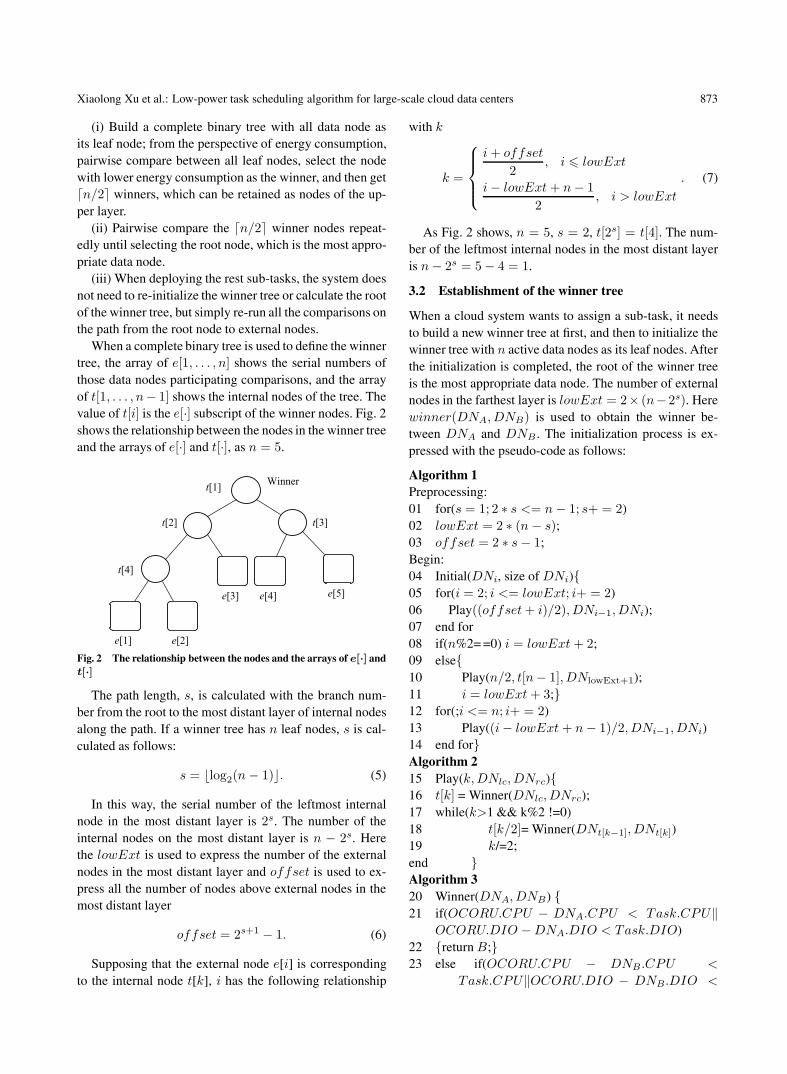
When a complete binary tree is used to define the winnertree, the array of e[1, . . . , n] shows the serial numbers ofthose data nodes participating comparisons, and the arrayof t[1, . . . , n− 1] shows the internal nodes of the tree. Thevalue of t[i] is the e[·] subscript of the winner nodes. Fig. 2shows the relationship between the nodes in the winner treeand the arrays of e[·] and t[·], as n = 5.
Fig. 2 The relationship between the nodes and the arrays of e[·] andt[·]
The path length, s, is calculated with the branch num-ber from the root to the most distant layer of internal nodesalong the path. If a winner tree has n leaf nodes, s is cal-culated as follows:
s = �log2(n − 1)�. (5)
In this way, the serial number of the leftmost internalnode in the most distant layer is 2s. The number of theinternal nodes on the most distant layer is n − 2s. Herethe lowExt is used to express the number of the externalnodes in the most distant layer and offset is used to ex-press all the number of nodes above external nodes in themost distant layer
offset = 2s+1 − 1. (6)
Supposing that the external node e[i] is correspondingto the internal node t[k], i has the following relationship
with k
k =
⎧⎪⎪⎨⎪⎪⎩
i + offset
2, i � lowExt
i − lowExt + n − 12
, i > lowExt
. (7)
As Fig. 2 shows, n = 5, s = 2, t[2s] = t[4]. The num-ber of the leftmost internal nodes in the most distant layeris n − 2s = 5 − 4 = 1.
3.2 Establishment of the winner tree
When a cloud system wants to assign a sub-task, it needsto build a new winner tree at first, and then to initialize thewinner tree with n active data nodes as its leaf nodes. Afterthe initialization is completed, the root of the winner treeis the most appropriate data node. The number of externalnodes in the farthest layer is lowExt = 2× (n−2s). Herewinner(DNA, DNB) is used to obtain the winner be-tween DNA and DNB . The initialization process is ex-pressed with the pseudo-code as follows:
Algorithm 1Preprocessing:01 for(s = 1; 2 ∗ s <= n − 1; s+ = 2)02 lowExt = 2 ∗ (n − s);03 offset = 2 ∗ s − 1;Begin:04 Initial(DNi, size of DNi){05 for(i = 2; i <= lowExt; i+ = 2)06 Play((offset + i)/2), DNi−1, DNi);07 end for08 if(n%2==0) i = lowExt + 2;09 else{10 Play(n/2, t[n− 1], DNlowExt+1);11 i = lowExt + 3;}12 for(;i <= n; i+ = 2)13 Play((i − lowExt + n − 1)/2, DNi−1, DNi)14 end for}Algorithm 215 Play(k, DNlc, DNrc){16 t[k] = Winner(DNlc, DNrc);17 while(k>1 && k%2 !=0)18 t[k/2]= Winner(DNt[k−1], DNt[k])19 k/=2;end }Algorithm 320 Winner(DNA, DNB) {21 if(OCORU.CPU − DNA.CPU < Task.CPU‖
OCORU.DIO − DNA.DIO < Task.DIO)22 {return B;}23 else if(OCORU.CPU − DNB.CPU <
Task.CPU‖OCORU.DIO − DNB.DIO <
874 Journal of Systems Engineering and Electronics Vol. 24, No. 5, October 2013
Task.DIO)24 {return A;}25 else{26 A= sqrt(((DNA.CPU + Task.CPU−
Perfrom.CPU )ˆ + (DNA.DIO + Task.DIO−Perfrom.DIO)ˆ))+ sqrt(((DNB.CPU−Perform.CPU )ˆ+(DNB.DIO−Perfrom.DIO)ˆ));
27 B= sqrt(((DNB.CPU + Task.CPU−Perfrom.CPU )ˆ + (DNB.DIO + Task.DIO−Perfrom.DIO)ˆ))+ sqrt(((DNA.CPU−Perform.CPU )ˆ+(DNA.DIO−Perfrom.DIO)ˆ));
28 return (A >= B) ? DNA:DNB;} }Firstly, Algorithm 1 initializes the values of s, lowExt
and offset, respectively and then:(i) Pairwise compare nodes from the external node DNi
in the most distant layer of the winner tree.(ii) Carry out the comparisons activated by the other n-
lowExt node. If n is odd, DNlowExt+1 will be the rightchild, otherwise be the left child. If n is odd, there arecomparisons between the internal nodes and the externalcodes. Its opponent is DNt[n−1] and its parent node isDNt[(n−1)/2].
(iii) Deal with the comparisons of the remaining exter-nal nodes from the leftmost of the remaining node of thewinner tree until getting the final winner.
The inputs of Algorithm 1 include the node states, theOCORU of the cloud data center and the requirements ofCPU and DIO utilization rate for processing the task; theoutput of Algorithm 1 is a complete binary tree, whose rootis the most appropriate data node.
Algorithm 2 is the implementation process of compa-risons. The process starts from DNk, and DNlc and DNrc
are respectively the left child and right child of DNk. Acomparison can be carried out when the right child of anode rises to the node; if its left child rises to it, the com-parison cannot be carried out, because the winner of theright child tree is not determined yet.
The input of Algorithm 2 is the output of Algorithm 1.However, the information of its root changes, which meansa new round of comparison should be organised. The out-put of Algorithm 2 is a new binary tree, whose root is themost appropriate data node. Although the ouputs of Algo-rithm 1 and Algorithm 2 are all binary trees, their construc-tion approaches are different.
Algorithm 3 is used to compare the leaf codes and selectthe winner node.
Referring to the research results provided in [15],we suppose that there are two data nodes, DNA andDNB . DNA.CPU is 30 and DNA.DIO is 30 (expressed
as (30, 30)); DNB .CPU is 40 and DNB.DIO is 10(expressed as (40, 10)). The master node will select oneof the two nodes to undertake a task with its require-ment (10, 10). The optimal allocation of resources in thecloud data center is (80, 50). This method firstly calculatesthe Euclidean distance δ: the initial distance of DNA isδAe ((30, 30)− (80, 50)) = 53.8, and the initial distance of
DNB is δBe ((40, 10) − (80, 50)) = 56.6. If the task was
assigned to DNA, the distance would be 41.2; if the taskwas allocated to DNB , the distance would be 42.4. There-fore, if the task is assigned to DNA, the total Euclideandistance between DNA and DNB would be greater.
The specific process of Algorithm 3 includes the follo-wing steps:
(i) Investigate whether a leaf node has extra computingpower to undertake the sub-task. If it does not meet therequirement OCORU.CPU − DN.CPU > Task.CPU
or OCORU.DIO − DN.DIO > Task.DIO, it will besentenced negative directly.
(ii) Calculate the Euclidean distances of DNA andDNB and pick up the node whose
∑δ is bigger.
The inputs of Algorithm 3 include CPU and DIO ofDNA and DNB , and the OCORU of the cloud data cen-ter; the output of Algorithm 3 is the winner node betweenDNA and DNB .
During the process of initializing the winner tree, thetime complexity of the first cycle of calculating s isO(log2 n), and the time complexity of the second and thirdcycles is O(n).
3.3 LTSA for a single task
Suppose that a cloud data center consists of n isomorphicactive data nodes {DN1, DN2, DN3, . . . , DNn} and k
dormant data nodes. The ith active data node is expressedas (DNi.CPU, DNi.DIO). The master node has divideda single task submitted by a user into Task.Amount
pieces of sub-tasks {SubTask1 = SubTask2 =SubTask3 = · · · = SubTaskTask.Amount} and then de-ploys them on data nodes. The OCORU of the cloud datacenter is (OCORU.CPU , OCORU.DIO), and all nodesare running under this value.
In the ideal case, the basic process of LTSA for a singletask (LTSA-S) includes the following steps: create a newwinner tree, set n data nodes as its leaf nodes, and initia-lize the winner tree, whose root node is the winnernode and can undertake one copy of sub-task; there areTask.Amount-1 copies of sub-tasks still not deployed onsuitable nodes; modify the winner of trees and repeat com-parisons until that all rest sub-tasks are deployed on suit-able data nodes, and return the array of these data nodes’IDs.
Xiaolong Xu et al.: Low-power task scheduling algorithm for large-scale cloud data centers 875
However, if there are too many sub-tasks or the clouddata center is too busy, it is very possible that the numberof active nodes is not enough. We build a winner tree todetermine the number of dormant nodes which need to beactivated. Supposing there are l remaining sub-tasks, l datanodes are set as the leaf nodes of the tree, and DN.CPU
and DN.DIO of these l data nodes are zero. After the ini-tialization is completed, comparisons will be repeated un-til that the l copies of sub-tasks are deployed successfullyand the array of these l data nodes’ IDs are returned. Thearray is checked and k data nodes are got and will not beassigned sub-tasks. l − k is the number of data nodes thatshould be activated. The winner tree is re-initialized, whichhas n active data nodes and l−k dormant data nodes as leafnodes. The final array points out the ultimate deploymentof task. The whole implementation process is describedwith the following pseudo-code.
The inputs of Algorithm 4 include all the nodes, theOCORU of the cloud data center and Task.CPU andTask.DIO; the output of Algorithm 4 is the winner tree,whose root node will be assigned a copy of sub-task. Theinput of Algorithm 5 is the output of Algorithm 4; the out-put of Algorithm 5 is a new winner tree. Unlike Algorithm2 and Algorithm 3, Algorithm 4 and Algorithm 5 considerthe insufficient situation of the active nodes and the reacti-vation of additional nodes.
Algorithm 4Begin:29 Initial(DNi, n);30 for each subTaskj
31 a[j] = t[1];32 Update();33 rePlay(DNwinner);34 end for35 if(all SubTaskj is done)36 return a[];37 else{38 for each SubTasklast
39 L++;40 end for41 Initial(DNk, L);42 for each SubTasklast
43 a[j] = t[1];44 Update( );45 rePlay(DNwinner);46 end for47 for each DNk null
48 K++;49 end for50 Initial((DNk, n + L − k);51 for each SubTaskj
52 a[j] = t[1];53 Update( );54 rePlay(DNwinner);55 end for56 return a;}Algorithm 557 rePlay(DNi){58 if(i <= lowExt){59 k = (offset + i)/2;60 lc = 2 ∗ k − offset;61 rc = lc + 1;}62 else{63 k = (i − lowExt + n − 1)/2;64 if(2 ∗ k == n − 1){lc = t[2 ∗ k]; rc = i}65 else{lc = 2 ∗ k − n + 1 + lowExt; rc = lc + 1;}}66 end if67 t[k]=Winner(DNlc, DNrc);68 k/=2;69 for(;k >= 1; k/=2)70 t[k]= Winner(DNt[2∗k], DNt[2∗k+1])71 end for}
The time complexity of the winner tree initializationprocess is O(n). On this basis, the time complexity of re-constructing each winner tree is O(log2 n). The time com-plexity of the whole process is O(n log2 n).
3.4 LTSA for multi-task
The cloud system is an open, large-scale multi-user sys-tem, which greatly increases the complexity of the taskscheduling problem. It is likely that multiple users sub-mit their respective tasks at the same time. Suppose thatthere are two tasks of (10, 10) and (50, 20) submitted atthe same time. The initialization algorithm assigns the taskof (10, 10) to DNA, which changes to (40, 40). At thistime, a dormant node needs to be activated for deploy-ing the task of (50, 20), resulting in three data nodes, (40,40), (40, 20) and (50, 20). If the task of (50, 20) deployedfirst, we can see that only DNA has the ability to carrythe task, and then assign it to DNA. Then deploy the taskof (10, 10). Now, only DNB has the ability to carry thetask. Therefor assign the task to DNB . Ultimately, thereare only two data nodes, (80, 50) and (50, 50). The firstdistribution needs one more data node than the second, andeach data node distance value has a gap with the optimalresource allocation. From the energy point of view, the sec-ond allocation is clearly more reasonable.
The prior deployment of heavy tasks to light tasks canoften take advantage of the flexibility of light tasks to uti-lize the rest resources of data nodes in order to reach the
876 Journal of Systems Engineering and Electronics Vol. 24, No. 5, October 2013
optimal allocation of resources, rather than activating moredormant nodes.
Suppose that there are two tasks (10, 10) and (50,20). According to 10 <50 and 10 <20, it is very intuitive tojudge the workload of task. However, supposing there aretwo tasks (10, 20) and (20, 10), the original way will not befeasible. To solve this problem, we define a task comparingcoefficient.
Definition 6 Weight is the task comparing coefficient,which can be calculated with the following formula
Weighti =Taski.CPU
OCORU.CPU+
Taski.DIO
OCORU.DIO. (7)
Typically, the values of OCORU.CPU are not close tovalues of OCORU.DIO. Therefore, in order to realize thefair comparison among tasks, it is necessary to differentiatethe task requirement of CPU and DIO and to give differ-ent proportions in accordance with the optimal allocation
of resources1
OCORU.CPUis the proportion of CPU
that task requires, and1
OCORU.DIOis the proportion
of DIO that task requires. Supposing (OCORU.CPU ,OCORU.DIO) = (80, 50), the Weight of (10, 20) is 0.525,and the Weight of (20, 10) is 0.45. Therefore the task (10,20) is greater than the task (20, 10).
The LTSA for multi-task (LTSA-M) takes the schedu-ling principle of big task priority, whose basic idea is: sortall tasks by the winner tree, and select the task with re-latively large Weight as the winner node; repeat compar-isons until getting a task queue with descending priority;the master node keeps reallocating tasks by the task queueuntil all tasks are allocated successfully. The whole imple-mentation process is described by the pseudo-code as fol-lows:
Algorithm 672 Initial(Taski, m);73 for each Taski
74 A[j] = T [1];75 Update(Taskwinner);76 rePlay();77 end for78 for i = 1; i < m; i++;79 get SubTask from a[i];80 do Algorithm 5;81 end for
The time complexity of a single task deployment isO(n log2 n), which means that m tasks need for m
times of deployment. Therefore the time complexity isO(mn log2 n). In a cloud data center, usually the numberof processing tasks at the same time is much smaller than
the number of subtasks. The time complexity of Algorithm6 can be approximated as O(n log2 n).
4. Experiments and performance analysis
We carry out a series of experiments to compare LTSAwith the original resource integration algorithm (RIA) [15]and analyze their performances about the time require-ment for scheduling, the node ratio of low utilization,the number of dormant nodes and the energy consump-tion. We construct a simulation test platform based onthe laboratory intranet environment. OCORU.CPU andOCORU.DIO is set as (80, 50). In order to simulate theactual complex situation of a large-scale cloud data center,each Task.CPU and Task.DIO are generated randomlyfrom (1, 1) to (80, 50) by the system. We set 300 pieces oftasks. Each of them is cut randomly into 1 to 100 pieces ofsub-tasks by the system. Each DN.CPU and DN.DIO
are generated randomly from (1, 1) to (80, 50). As nodestates and task states are both generated randomly, in orderto reflect the actual situation more accurately, all experi-mental results are averaged with the results of 100 timesexperiments.
4.1 Analysis on the time requirement for scheduling
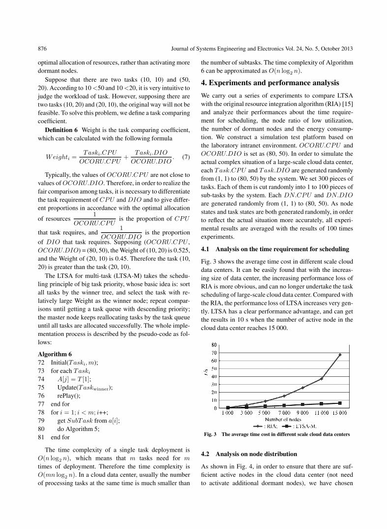
Fig. 3 shows the average time cost in different scale clouddata centers. It can be easily found that with the increas-ing size of data center, the increasing performance loss ofRIA is more obvious, and can no longer undertake the taskscheduling of large-scale cloud data center. Compared withthe RIA, the performance loss of LTSA increases very gen-tly. LTSA has a clear performance advantage, and can getthe results in 10 s when the number of active node in thecloud data center reaches 15 000.
Fig. 3 The average time cost in different scale cloud data centers
4.2 Analysis on node distribution
As shown in Fig. 4, in order to ensure that there are suf-ficient active nodes in the cloud data center (not needto activate additional dormant nodes), we have chosen

Xiaolong Xu et al.: Low-power task scheduling algorithm for large-scale cloud data centers 877
to deploy small number of tasks. IfDNi.CPU
ORCRU.CPU+
DNi.DIO
RCRU.CPU< 1, DNi could be considered in the low
utilization state. Initial in Fig. 4 represents the percentageof the initial low utilization ratio of data nodes before be-ing allocated tasks. We can see that LTSA-M strategy canbe more effective to reduce the low utilization rate of activenodes than both Initial and FCFS.
Fig. 4 The ratio of low utilization nodes with different numbers oftasks
As shown in Fig. 5, with the number of tasks increas-ing gradually, the cloud data center needs to activate moredormant nodes in order to meet tasks’ requirements. Com-pared with FCFS, LTSA-M activates fewer dormant nodesto complete all tasks because of its more appropriate taskpriority order. When the number of tasks is 1 800, LTSAonly needs to activate a very small number of dormantnodes to complete all tasks, while FCFS activates almostall dormant nodes.
Fig. 5 The number of dormant nodes activated
According to Fig. 4 and Fig. 5, it can be found that,compared with FCFS, LTSA-M can match the computingpower of each node to the workload of assigned sub-tasksmore to avoid the energy waste caused by the node whichcannot be taken full advantage of; what is more, the num-ber of active nodes can make match with the current work
load of tasks, and the number of the unnecessary activenodes is effectively reduced.
4.3 Analysis on energy consumption
In the lab environment, we build a small cloud data centerwith PCs, which hardware configurations are all the same:Intel Pentium (R), Dual E2180 processor, 2.0 GHz of theCPU frequency, 1 GB of memory and 250 GB of hard diskspace. Each host is equipped with a power meter.
Here select two tasks, Mix1 and Mix2, and each taskconsists of eight different sub-tasks assigned to the clouddata center based on different scheduling algorithms. Thetask parameters are shown as Table 1.
Table 1 Parameters of tasks
Task node Mix1(CPU, DIO) Mix2(CPU, DIO)
1 (39,30) (40,20)2 (38,29) (15,30)3 (42,34.5) (10,40)4 (37,30) (50,20)5 (41,33) (10,40)6 (42,30.25) (70,14)7 (40,31.25) (80,20)8 (42,34) (60,50)
As shown in Fig. 6, the experimental results of FCFSand LTSA-M are very close in processing Mix1 (the dif-ference among Mix1 is not that much). Their energy con-sumptions are very close. The difference among Mix2 ismore obvious. Compared with FCFS, LTSA-M is closer tothe optimal strategy, and more outstanding in energy effi-ciency.
Fig. 6 The comparison of FCFS and LTSA-M
5. Conclusions
This paper presents a novel low-power task schedulingstrategy for large-scale cloud data centers. We introducethe winner tree to make the data nodes as the leaf nodesof the tree, and then select the final winner on the pur-pose of reducing energy consumption. We fully considerthe complexity of large-scale cloud data centers, and de-fine the task comparison coefficient to make task schedul-

878 Journal of Systems Engineering and Electronics Vol. 24, No. 5, October 2013
ing strategy more reasonable while the cloud data centerhandles multiple tasks at the same time.
In this paper, we only consider parameter CPU andDIO. How to consider more factors to reduce energy con-sumption further in more complex situations will be thefocus of our future study.
References
[1] C. Lin, Y. Tian, M. Yao. Green network and green evalua-tion: mechanism, modeling and evaluation. Chinese Journalof Computers, 2011, 34(4): 594–612. (in Chinese)
[2] Global Action Plan. An inefficient truth. http://globalactionplan.org.uk.
[3] F. Zhang, F. A. Antonio, L. Wang, et al. Network energyconsumption models and energy efficient algorithms. ChineseJournal of Computers, 2012, 35(3): 604–615. (in Chinese)
[4] R. Kumar. Data center power and cooling scenario through2015. http://www.gartner.com/id=502230.
[5] K. D. Lange. The next frontier for power/performance bench-marking: energy efficiency of storage subsystems. Proc. ofthe Standard Performance Evaluation Corporation (SPEC)Benchmark Workshop, 2009: 97–101.
[6] K. H. Kim, R. Buyya, J. Kim. Power aware scheduling ofbag-of-tasks applications with deadline constraints on DVS-enabled clusters. Proc. of the 7th IEEE International Sympo-sium on Cluster Computing and the Grid, 2007: 541–548.
[7] L. Wang, L. G. Von, J. Dayal. Towards energy aware schedul-ing for precedence constrained parallel tasks in a cluster withDVFS. Proc. of the 10th IEEE/ACM International Symposiumon Cluster, Cloud and Grid Computing, 2010: 368–377.
[8] E. V. Carrera, E. Pinheiro, R. Bianchini. Conserving disk en-ergy in network servers. Proc. of the 17th Annual InternationalConference on Supercomputing, 2003: 79–86.
[9] J. Kang, S. Ranka. Dynamic slack allocation algorithms forenergy minimization on parallel machines. Journal of Paralleland Distributed Computing, 2010, 70(5): 417–430.
[10] R. Raghavendra, P. Ranganathan, V. Talwar, et al. No powerstruggles: coordinated multi-level power management for thedata center. Proc. of the 13th International Conference on Ar-
chitectural Support for Programming Languages and Operat-ing Systems, 2008: 48–59.
[11] C. Lefurgy, X. Wang, M. Ware. Power capping: a prelude topower shifting. Cluster Computing, 2008, 11(2): 183–195.
[12] G. Dhiman, G. Marchetti, T. Rosing. Green: a system for en-ergy efficient computing in virtualized environments. Proc. of
the 14th ACM/IEEE International Symposium on Low PowerElectronics and Design, 2009: 243–248.
[13] Y. Wang, X. Wang. Power optimization with performanceassurance for multi-tier applications in virtualized data cen-
ters. Proc. of the 39th International Conference on ParallelProcessing Workshops, 2010: 512–519.
[14] R. Nathuji, K. Schwan. Virtualpower: coordinated power man-agement in virtualized enterprise systems. Proc. of the 21st
ACM/SIGOPS Symposium on Operating Systems Principles,2007: 265–278.
[15] S. Srikantaiah, A. Kansal, F. Zhao. Energy aware consolida-tion for cloud computing. Proc. of the USENIX Workshop onPower Aware Computing and Systems, 2008.
[16] J. Torres, D. Carrera, K. Hogan, et al. Reducing wasted re-sources to help achieve green data centers. Proc. of the IEEEInternational Symposium on Parallel and Distributed Process-ing, 2008: 8–10.
[17] A. J. Younge, L. G. Von, L. Wang, et al. Efficient resourcemanagement for cloud computing environments. Proc. of the
IEEE International Green Computing Conference, 2010: 233–236.
Biographies
Xiaolong Xu was born in 1977. He is a Ph.D. andan associate professor in Nanjing University of Postsand Telecommunications. His research interests arecloud computing, P2P computing, intelligent agentand information security.E-mail: [email protected]
Jiaxing Wu was born in 1988. He is a graduate stu-dent in Nanjing University of Posts and Telecom-munications. His research interests are cloud com-puting and intelligent agent.E-mail: [email protected]
Geng Yang was born in 1961. He is a Ph.D. anda professor in Nanjing University of Posts andTelecommunications. His research interests arecloud computing, information security and sensornetworks.E-mail: [email protected]
Ruchuan Wang was born in 1943. He is a professorin Nanjing University of Posts and Telecommunica-tions. His research interests are computer software,computer network, distributed computing, informa-tion security and sensor networks.E-mail: [email protected]