loose tube - na.prysmiangroup.com
TRANSCRIPT
PRO
1 0
3/15
/201
6-V
9
Table of Contents page 1.0 Scope .......................................................................... 12.0 Safety ........................................................................ 13.0 Key Points .......................................................... 1-24.0 Reference Drawing ........................................... 25.0 Tools and Materials Needed ....................... 26.0 End of Cable Access ..................................... 3-57.0 Midspan Access ............................................. 6-8 8.0 Closure or Pedestal Termination............. 9
1.0 ScopeThis document provides instruction for the preparation and handling of loose tube, ADSS, and Microduct fiber optic cable. The instructions in this document explain how to prepare end openings and midspan openings of loose tube fiber optic cable. When this cable is used in conjunction with splice closures, cabinets, pedestals, hardware, etc., the user must obtain installation procedures from the appropriate component manufacturers. Failure to adhere to preparation and handling procedures may void the cable warranty.
Please call if you have any questions at 1-800-669-0808 or 1-800-879-9862
2.0 Safety2.1 It is recommended that approved personal protective equipment be used.
2.2 Wear safety glasses and gloves, and use solvents in well ventilated areas.
2.3 Never look directly into the end of a fiber that may be carrying laser light. Laser light may be invisible and can damage your eyes. Viewing it directly does not cause pain. The iris of the eye will not close involuntarily as when viewing a bright light. Consequently, serious damage to the retina of the eye is possible. Should accidental eye exposure to laser light be suspected, arrange for an eye examina-tion immediately.
2.4 DO NOT use magnifiers in the presence of laser radiation. Diffused laser light can cause eye damage if focused with optical instruments. Should accidental eye exposure be suspected, arrange for an eye exam immediately.
3.0 Key Points3.1 The minimum cable bend radius during installation (while under tension) is 20 times the cable diameter. The minimum long term static bend radius is 10 times the cable diameter unless specified otherwise in the data sheet.
3.2 DO NOT leave more than the rated length of exposed (bare) buffer tube in closures, cabinets, pedestals, etc. Exposing buffer tubes beyond the rated length may lead to attenuation increase.If a longer buffer tube storage length is needed, remove the buffer tube and place the fiber in splice trays or inside spiral wrap.
Figure 1 Maximum Express Tube Storage Length
Product Brand
Cable Design Buffer Tube OD
Buffer Tube
Material
Max Length
(mm) ft (m)
Prysmian ExpressLT 2.5 PP 20 (6)
Prysmian ExtremeLink 3.0 PP or PBT 20 (6)
Prysmian LT20 with BBXS 2.0 PP 20 (6)
Prysmian FlexLink 2.65 or 2.5 HDPE not rated
Prysmian ADSS Short Span 3.0 PP 20 (6)
Prysmian ADSS Long Span (12 f/tube) 2.6 PBT 14 (4.3)
Prysmian ADSS Long Span (24 f/tube) 3.0 PBT 16 (4.9)
Prysmian Microduct (MDS1JKT-12) 1.9 PBT not rated
Prysmian Microduct (MDL1JKT-12) 2.5 PP 20 (6)
Prysmian Microduct (MDS1JKT-24) 3 PBT 16 (4.9)
Prysmian Microduct (MD 1JKT or MD3JKT) 1.9 PBT 8 (24)
Prysmian Microduct (MDM1JKT) 1.5 PBT 8 (24)
Prysmian Dry FlexLink (to 2014) 2.8 PP 20 (6)
Draka LT2.7 (Jan 2007 to 2012) 2.7 or 2.5 PP 20 (6)
Draka Loose Tube (from 2002 to 2006) 2.5 PP 8 (2.4)
3.3 DO NOT allow blades or sharp edges to contact the fibers. 3.4 Central strength member MUST be tightly secured in the closing to prevent expansion/contraction and potential attenuation increase.
3.5 Jacket sheath MUST be tightly secured inside the closure, pedestal, cabinet, etc., to prevent expansion/contraction and potential attenuation increase.
3.6 DO NOT exceed the minimum bend radius.
3.7 DO NOT exceed the maximum pull tension.
1
Loose Tube Preparation & Handling Procedure
PRO
1 0
3/15
/201
6-V
9
[+] Cable ring cutter, sheath knife, or utility knife (Alternative-Prysmian’s Cable Jacket Slitter) [+] Pliers – needle nose, diagonal, or linesman [+] Diagonal cutters [+] Scissors or snips [+] Flat-tip screwdriver [+] Cable cleaning solution D’Gel [+] Lint free wipes [+] 99% propanol alcohol [+] Disposable rags 6.0 End of Cable Access ProcedureQuick Reference Checklist
1. Remove jacket and armoring (if applicable) [+] Measure access length and make ring cuts.[+] Score armor, flex and pull off 6" section from cable end[+] Notch armor/sheath and pull ripcords.[+] Remove jacket and armor.
2. Prepare the cable core.[+] Cut and remove yarns, binders, unnecessary filler rods.[+] Separate buffer tubes from central strength member (CSM).[+] Cut CSM to proper length.
3. Prepare buffer tubes and fibers.[+] Score & remove buffer tubes in < 4 foot sections. For gel-filled tubes < 0oC (32oF), do not remove more than 2 ft. sections. Prysmian Buffer Tube Access Tools are recommended for midspan access.[+] DO NOT leave more than the rated length of exposed buffer tube.[+] Clean fibers and prepare for splicing.
5.0 Tools and Materials Needed3.8 When removing buffer tubes, keep the fibers pulled tight and straight to prevent fiber breaks. Pull the buffer tube off of the fibers rather than pushing. DO NOT attempt to remove more than 4 feet of buffer tube at a time. If the tube temperature is < 0oC (32oF) and the tube is gel-filled, DO NOT REMOVE MORE THAN 2 FEET of tube at a time.
3.9 DO NOT BEND BUFFER TUBES AT SHARP ANGLES while removing the jacket, armor, yarns, or strength members.
3.10 Prysmian Buffer Tube Access Tools are highly recommended for midspan access of fibers in the buffer tubes to prevent fiber damage.
3.11 Prysmian ADSS jackets are applied utilizing a pressure method to obtain appropriate contact between the jacket and the aramid strength yarns. The process removes the possibility of a “loose” jacket and ensures proper operation of the ADSS hardware.
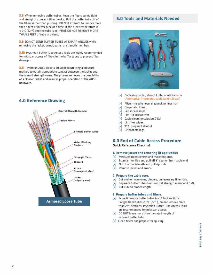
Armored Loose Tube
4.0 Reference Drawing
Flexible Buffer Tubes
Jacket(polyethylene)
Strength Yarns
Armor(corrugated steel)
..........
..........
......
..........
..........
Ripcord
..........
..........
...
..........
.....
..........
..........
..........
......
Water BlockingBinders
..........
..........
..........
.
Central Strength Member
..........
..........
..........
.
Optical Fibers
..........
......
2
PRO
1 0
3/15
/201
6-V
9
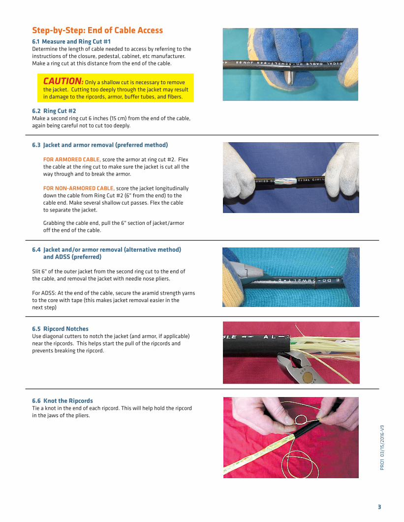
Step-by-Step: End of Cable Access6.1 Measure and Ring Cut #1 Determine the length of cable needed to access by referring to the instructions of the closure, pedestal, cabinet, etc manufacturer. Make a ring cut at this distance from the end of the cable.
CAUTION: Only a shallow cut is necessary to remove the jacket. Cutting too deeply through the jacket may result in damage to the ripcords, armor, buffer tubes, and fibers.
6.2 Ring Cut #2 Make a second ring cut 6 inches (15 cm) from the end of the cable, again being careful not to cut too deeply.
6.3 Jacket and armor removal (preferred method)
FOR ARMORED CABLE, score the armor at ring cut #2. Flex the cable at the ring cut to make sure the jacket is cut all the way through and to break the armor.
FOR NON-ARMORED CABLE, score the jacket longitudinally down the cable from Ring Cut #2 (6" from the end) to the cable end. Make several shallow cut passes. Flex the cable to separate the jacket.
Grabbing the cable end, pull the 6" section of jacket/armor off the end of the cable.
6.4 Jacket and/or armor removal (alternative method) and ADSS (preferred)
Slit 6" of the outer jacket from the second ring cut to the end of the cable, and removal the jacket with needle nose pliers.
For ADSS: At the end of the cable, secure the aramid strength yarns to the core with tape (this makes jacket removal easier in the next step)
6.5 Ripcord Notches Use diagonal cutters to notch the jacket (and armor, if applicable) near the ripcords. This helps start the pull of the ripcords and prevents breaking the ripcord.
6.6 Knot the Ripcords Tie a knot in the end of each ripcord. This will help hold the ripcord in the jaws of the pliers.
3
PRO
1 0
3/15
/201
6-V
9
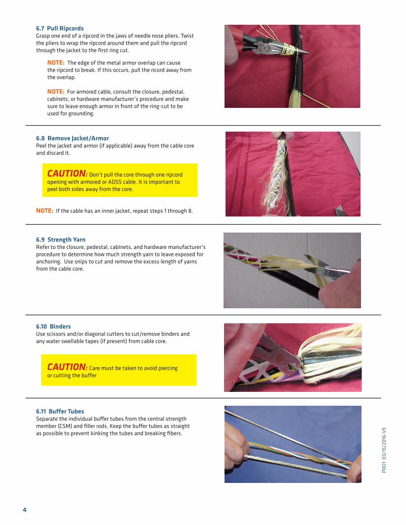
6.7 Pull Ripcords Grasp one end of a ripcord in the jaws of needle nose pliers. Twist the pliers to wrap the ripcord around them and pull the ripcord through the jacket to the first ring cut. NOTE: The edge of the metal armor overlap can cause the ripcord to break. If this occurs, pull the ricord away from the overlap.
NOTE: For armored cable, consult the closure, pedestal, cabinets, or hardware manufacturer’s procedure and make sure to leave enough armor in front of the ring-cut to be used for grounding.
6.8 Remove Jacket/Armor Peel the jacket and armor (if applicable) away from the cable core and discard it.
CAUTION: Don’t pull the core through one ripcord opening with armored or ADSS cable. It is important to peel both sides away from the core.
NOTE: If the cable has an inner jacket, repeat steps 1 through 8.
6.9 Strength Yarn Refer to the closure, pedestal, cabinets, and hardware manufacturer’s procedure to determine how much strength yarn to leave exposed for anchoring. Use snips to cut and remove the excess length of yarns from the cable core.
6.10 Binders Use scissors and/or diagonal cutters to cut/remove binders and any water swellable tapes (if present) from cable core.
CAUTION: Care must be taken to avoid piercing or cutting the buffer
6.11 Buffer Tubes Separate the individual buffer tubes from the central strength member (CSM) and filler rods. Keep the buffer tubes as straight as possible to prevent kinking the tubes and breaking fibers.
4
PRO
1 0
3/15
/201
6-V
9
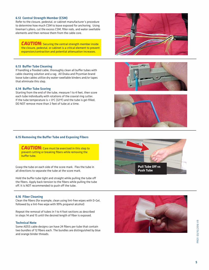
6.12 Central Strength Member (CSM) Refer to the closure, pedestal, or cabinet manufacturer’s procedure to determine how much CSM to leave exposed for anchoring. Using lineman’s pliers, cut the excess CSM, filler rods, and water swellable elements and then remove them from the cable core.
CAUTION: Securing the central strength member inside the closure, pedestal, or cabinet is a critical element to prevent expansion/contraction and potential attenuation increases.
6.13 Buffer Tube Cleaning If handling a flooded cable, thoroughly clean all buffer tubes with cable cleaning solution and a rag. All Draka and Prysmian brand loose tube cables utilize dry water-swellable binders and/or tapes that eliminate this step.
6.14 Buffer Tube Scoring Starting from the end of the tube, measure 1 to 4 feet, then score each tube individually with rotations of the coaxial ring cutter.If the tube temperature is < 0oC (32oF) and the tube is gel-filled, DO NOT remove more than 2 feet of tube at a time.
6.15 Removing the Buffer Tube and Exposing Fibers
CAUTION: Care must be exercised in this step to prevent cutting or breaking fibers while removing the buffer tube.
Grasp the tube on each side of the score mark. Flex the tube in all directions to separate the tube at the score mark.
Hold the buffer tube tight and straight while pulling the tube off the fibers. Apply back-tension to the fibers while pulling the tube off. It is NOT recommended to push off the tube.
6.16 Fiber Cleaning Clean the fibers (for example, clean using lint-free wipes with D-Gel, followed by a lint-free wipe with 99% propanol alcohol)
Repeat the removal of tubes in 1 to 4 foot sections as described in steps 14 and 15 until the desired length of fiber is exposed.
Technical NoteSome ADSS cable designs can have 24 fibers per tube that contain two bundles of 12 fibers each. The bundles are distinguished by blue and orange binder threads.
5
Pull Tube Off vs Push Tube
PRO
1 0
3/15
/201
6-V
9
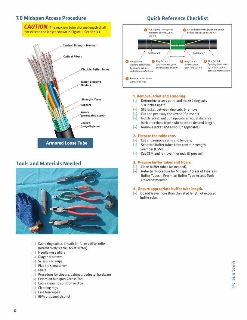
1. Remove jacket and armoring. [+] Determine access point and make 2 ring cuts 5-8 inches apart.[+] Slit jacket between ring cuts & remove.[+] Cut and pry away the armor (if present).[+] Notch jacket and pull ripcords an equal distance both directions from switchback to desired length.[+] Remove jacket and armor (if applicable).
2. Prepare the cable core.[+] Cut and remove yarns and binders.[+] Separate buffer tubes from central strength member (CSM).[+] Cut CSM and remove filler rods (if present).
3. Prepare buffer tubes and fibers.[+] Clean buffer tubes (as needed).[+] Refer to “Procedure for Midspan Access of Fibers in Buffer Tubes”. Prysmian Buffer Tube Access Tools are recommended.
4. Ensure appropriate buffer tube length.[+] Do not leave more than the rated length of exposed buffer tube.
Tools and Materials Needed
[+] Cable ring cutter, sheath knife, or utility knife (alternatively, cable jacket slitter) [+] Needle nose pliers [+] Diagonal cutters [+] Scissors or snips [+] Flat-tip screwdriver [+] Pliers [+] Procedure for closure, cabinet, pedestal hardware [+] Prysmian Midspan Access Tool [+] Cable cleaning solution or D’Gel [+] Cleaning rags [+] Lint free wipes [+] 99% propanol alcohol
6
7.0 Midspan Access Procedure CAUTION: The maxium tube storage length shall not exceed the length shown in Figure 1, Section 3.1.
Armored Loose Tube
Flexible Buffer Tubes
Jacket(polyethylene)
Strength Yarns
Armor(corrugated steel)
..........
..........
......
..........
..........
Ripcord
..........
..........
...
..........
.....
..........
..........
..........
......
Water BlockingBinders
..........
..........
..........
.
Central Strength Member
..........
..........
..........
.
Optical Fibers
..........
...... 8“
Ring Cut #1:Locate desired point and make Ring Cut #1
1 Ring Cut #2:8 inches awayfrom Ring Cut # 1
2
Pull Ripcord Pull Ripcord
4 5Ring Cut #3:Opening determined by closure, cabinet, pedestal manufacturer
7
Ring Cut #4:Opening determined by closure, cabinet, pedestal manufacturer
Pull Ripcords in opposite directions to Ring Cut #3 and #4
Slit and remove the jacket and armor between Ring Cut #1 and #2
Remove jacket, armor, yarns, filler rods
Quick Reference Checklist
6 3
PRO
1 0
3/15
/201
6-V
9
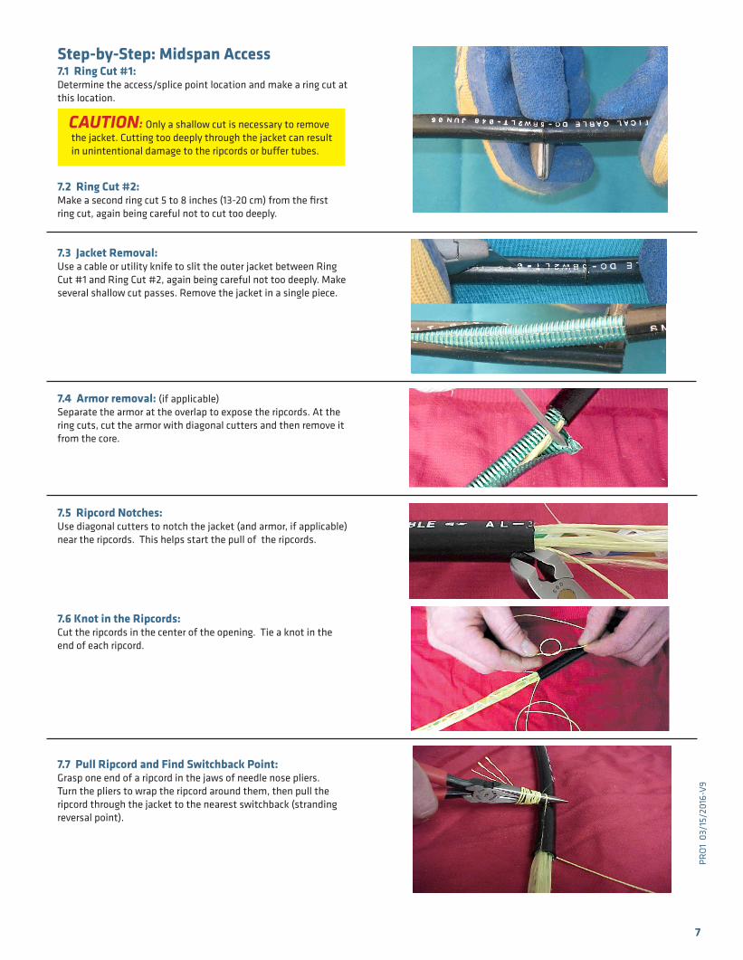
Step-by-Step: Midspan Access
7.1 Ring Cut #1: Determine the access/splice point location and make a ring cut at this location.
CAUTION: Only a shallow cut is necessary to remove the jacket. Cutting too deeply through the jacket can result in unintentional damage to the ripcords or buffer tubes.
7.2 Ring Cut #2: Make a second ring cut 5 to 8 inches (13-20 cm) from the first ring cut, again being careful not to cut too deeply.
7.3 Jacket Removal:Use a cable or utility knife to slit the outer jacket between Ring Cut #1 and Ring Cut #2, again being careful not too deeply. Make several shallow cut passes. Remove the jacket in a single piece.
7.4 Armor removal: (if applicable)Separate the armor at the overlap to expose the ripcords. At the ring cuts, cut the armor with diagonal cutters and then remove it from the core.
7.5 Ripcord Notches: Use diagonal cutters to notch the jacket (and armor, if applicable) near the ripcords. This helps start the pull of the ripcords.
7.6 Knot in the Ripcords: Cut the ripcords in the center of the opening. Tie a knot in theend of each ripcord.
7.7 Pull Ripcord and Find Switchback Point:Grasp one end of a ripcord in the jaws of needle nose pliers. Turn the pliers to wrap the ripcord around them, then pull the ripcord through the jacket to the nearest switchback (stranding reversal point).
7
PRO
1 0
3/15
/201
6-V
9
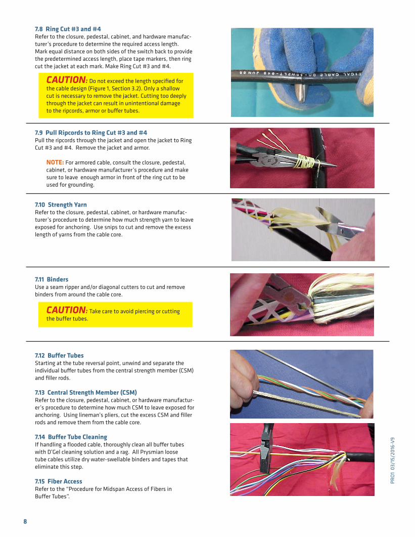
7.8 Ring Cut #3 and #4Refer to the closure, pedestal, cabinet, and hardware manufac-turer’s procedure to determine the required access length. Mark equal distance on both sides of the switch back to provide the predetermined access length, place tape markers, then ring cut the jacket at each mark. Make Ring Cut #3 and #4.
CAUTION: Do not exceed the length specified for the cable design (Figure 1, Section 3.2). Only a shallow cut is necessary to remove the jacket. Cutting too deeply through the jacket can result in unintentional damage to the ripcords, armor or buffer tubes.
7.9 Pull Ripcords to Ring Cut #3 and #4 Pull the ripcords through the jacket and open the jacket to Ring Cut #3 and #4. Remove the jacket and armor.
NOTE: For armored cable, consult the closure, pedestal, cabinet, or hardware manufacturer’s procedure and make sure to leave enough armor in front of the ring cut to be used for grounding.
7.10 Strength Yarn Refer to the closure, pedestal, cabinet, or hardware manufac-turer’s procedure to determine how much strength yarn to leave exposed for anchoring. Use snips to cut and remove the excess length of yarns from the cable core.
7.11 Binders Use a seam ripper and/or diagonal cutters to cut and remove binders from around the cable core.
CAUTION: Take care to avoid piercing or cutting the buffer tubes.
7.12 Buffer Tubes Starting at the tube reversal point, unwind and separate the individual buffer tubes from the central strength member (CSM) and filler rods. 7.13 Central Strength Member (CSM) Refer to the closure, pedestal, cabinet, or hardware manufactur-er’s procedure to determine how much CSM to leave exposed for anchoring. Using lineman’s pliers, cut the excess CSM and filler rods and remove them from the cable core.
7.14 Buffer Tube Cleaning If handling a flooded cable, thoroughly clean all buffer tubes with D’Gel cleaning solution and a rag. All Prysmian loose tube cables utilize dry water-swellable binders and tapes that eliminate this step.
7.15 Fiber Access Refer to the “Procedure for Midspan Access of Fibers in Buffer Tubes”.
8
PRO
1 0
3/15
/201
6-V
9
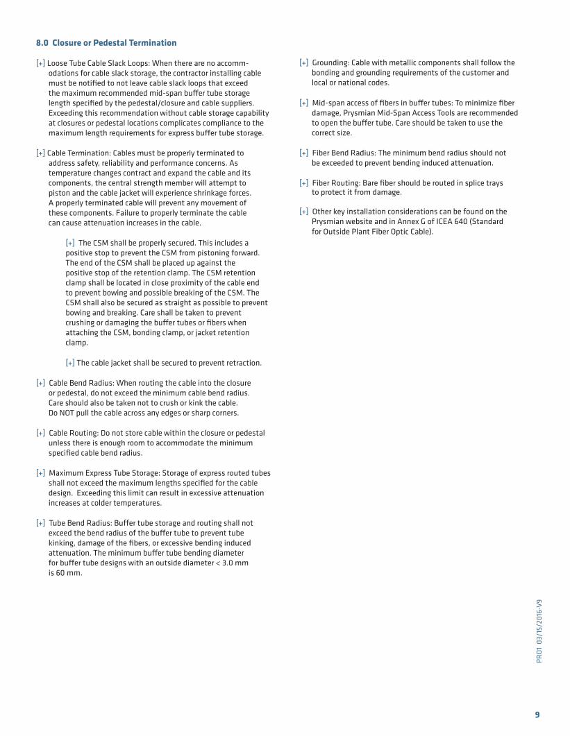
8.0 Closure or Pedestal Termination
[+] Loose Tube Cable Slack Loops: When there are no accomm-odations for cable slack storage, the contractor installing cable must be notified to not leave cable slack loops that exceed the maximum recommended mid-span buffer tube storage length specified by the pedestal/closure and cable suppliers. Exceeding this recommendation without cable storage capability at closures or pedestal locations complicates compliance to the maximum length requirements for express buffer tube storage.
[+] Cable Termination: Cables must be properly terminated to
address safety, reliability and performance concerns. As temperature changes contract and expand the cable and its components, the central strength member will attempt to piston and the cable jacket will experience shrinkage forces. A properly terminated cable will prevent any movement of these components. Failure to properly terminate the cable can cause attenuation increases in the cable.
[+] The CSM shall be properly secured. This includes a positive stop to prevent the CSM from pistoning forward.
The end of the CSM shall be placed up against the positive stop of the retention clamp. The CSM retention
clamp shall be located in close proximity of the cable end to prevent bowing and possible breaking of the CSM. The CSM shall also be secured as straight as possible to prevent bowing and breaking. Care shall be taken to prevent crushing or damaging the buffer tubes or fibers when attaching the CSM, bonding clamp, or jacket retention clamp.
[+] The cable jacket shall be secured to prevent retraction.
[+] Cable Bend Radius: When routing the cable into the closure or pedestal, do not exceed the minimum cable bend radius. Care should also be taken not to crush or kink the cable. Do NOT pull the cable across any edges or sharp corners.
[+] Cable Routing: Do not store cable within the closure or pedestal unless there is enough room to accommodate the minimum specified cable bend radius.
[+] Maximum Express Tube Storage: Storage of express routed tubes shall not exceed the maximum lengths specified for the cable design. Exceeding this limit can result in excessive attenuation increases at colder temperatures.
[+] Tube Bend Radius: Buffer tube storage and routing shall not exceed the bend radius of the buffer tube to prevent tube kinking, damage of the fibers, or excessive bending induced attenuation. The minimum buffer tube bending diameter for buffer tube designs with an outside diameter < 3.0 mm is 60 mm.
9
[+] Grounding: Cable with metallic components shall follow the bonding and grounding requirements of the customer and local or national codes.
[+] Mid-span access of fibers in buffer tubes: To minimize fiber damage, Prysmian Mid-Span Access Tools are recommended to open the buffer tube. Care should be taken to use the correct size.
[+] Fiber Bend Radius: The minimum bend radius should not be exceeded to prevent bending induced attenuation.
[+] Fiber Routing: Bare fiber should be routed in splice trays to protect it from damage.
[+] Other key installation considerations can be found on the Prysmian website and in Annex G of ICEA 640 (Standard for Outside Plant Fiber Optic Cable).
PRO
1 0
3/15
/201
6-V
9
Prysmian Group 700 Industrial Drive | Lexington, SC 29072 | +1-800-845-8507 | website: na.prysmiangroup.com
© DRAKA & PRYSMIAN - Brands of The Prysmian Group. 2016 All Right Reserved. The information contained within this document must not be copied, reprinted or reproduced in any form, either wholly or in part, without the written consent of Prysmian Group. The information is believed correct at the time of issue. Prysmian Group reserves the right to amend any specifications without notice. These specifications are not contractually valid unless specifically authorized by Prysmian Group. Issued March 2016.
DISCLAIMER OF WARRANTIES AND LIMITATION OF LIABILITIES
The practices contained herein are designed as a guide. Since there are numerous practices which may be utilized, Prysmian has tested and determined that the practices described herein are effective and efficient. The recom-mended practices are based on average conditions.
In addition, the materials and hardware referenced herein appear as examples, but in no way reflect the only tools and materials available to perform these evaluations.
Prysmian makes no representation of nor assumes any responsibility for its accuracy or completeness. Local, State, Federal Industry Codes and Regulations, as well as manufacturers requirements, must be consulted before proceeding with any project. Prysmian disclaims any liability arising from any information contained herein or for the absence of same.
For further information or assistance, contact:
Prysmian Field Services Department700 Industrial DriveLexington, SC 29072-3799803-951-4800FAX (803) 957-4628
OR
Prysmian Applications Engineering Department710 Industrial Dr.Lexington, SC 29072-3799803-951-4800FAX (803) 951-4044