logix5000 controllers sequential function charts ... · activities including installation,...
TRANSCRIPT

Programming Manual
Logix 5000 Controllers Sequential Function Charts 1756 ControlLogix, 1756 GuardLogix, 1769 CompactLogix, 1769 Compact GuardLogix, 1789 SoftLogix, 5069 CompactLogix, 5069 Compact GuardLogix, Studio 5000 Logix Emulate
Important user information Read this document and the documents listed in the additional resources section about installation, configuration, and operation of this equipment before you install, configure, operate, or maintain this product. Users are required to familiarize themselves with installation and wiring instructions in addition to requirements of all applicable codes, laws, and standards.
Activities including installation, adjustments, putting into service, use, assembly, disassembly, and maintenance are required to be carried out by suitably trained personnel in accordance with applicable code of practice. If this equipment is used in a manner not specified by the manufacturer, the protection provided by the equipment may be impaired.
In no event will Rockwell Automation, Inc. be responsible or liable for indirect or consequential damages resulting from the use or application of this equipment.
The examples and diagrams in this manual are included solely for illustrative purposes. Because of the many variables and requirements associated with any particular installation, Rockwell Automation, Inc. cannot assume responsibility or liability for actual use based on the examples and diagrams.
No patent liability is assumed by Rockwell Automation, Inc. with respect to use of information, circuits, equipment, or software described in this manual.
Reproduction of the contents of this manual, in whole or in part, without written permission of Rockwell Automation, Inc., is prohibited.
Throughout this manual, when necessary, we use notes to make you aware of safety considerations.
WARNING: Identifies information about practices or circumstances that can cause an explosion in a hazardous environment, which may lead to personal injury or death, property damage, or economic loss.
ATTENTION: Identifies information about practices or circumstances that can lead to personal injury or death, property damage, or economic loss. Attentions help you identify a hazard, avoid a hazard, and recognize the consequence
Important: Identifies information that is critical for successful application and understanding of the product.
Labels may also be on or inside the equipment to provide specific precautions.
SHOCK HAZARD: Labels may be on or inside the equipment, for example, a drive or motor, to alert people that dangerous voltage may be present.
BURN HAZARD: Labels may be on or inside the equipment, for example, a drive or motor, to alert people that surfaces may reach dangerous temperatures.
ARC FLASH HAZARD: Labels may be on or inside the equipment, for example, a motor control center, to alert people to potential Arc Flash. Arc Flash will cause severe injury or death. Wear proper Personal Protective Equipment (PPE). Follow ALL Regulatory requirements for safe work practices and for Personal Protective Equipment (PPE).
Allen-Bradley, Rockwell Software, Rockwell Automation, and TechConnect are trademarks of Rockwell Automation, Inc.
Trademarks not belonging to Rockwell Automation are property of their respective companies.
Rockwell Automation Publication 1756-PM006I-EN-P - February 2018 3
Summary of changes
This manual includes new and updated information. Use these reference tables to locate changed information.
Grammatical and editorial style changes are not included in this summary.
Global changes
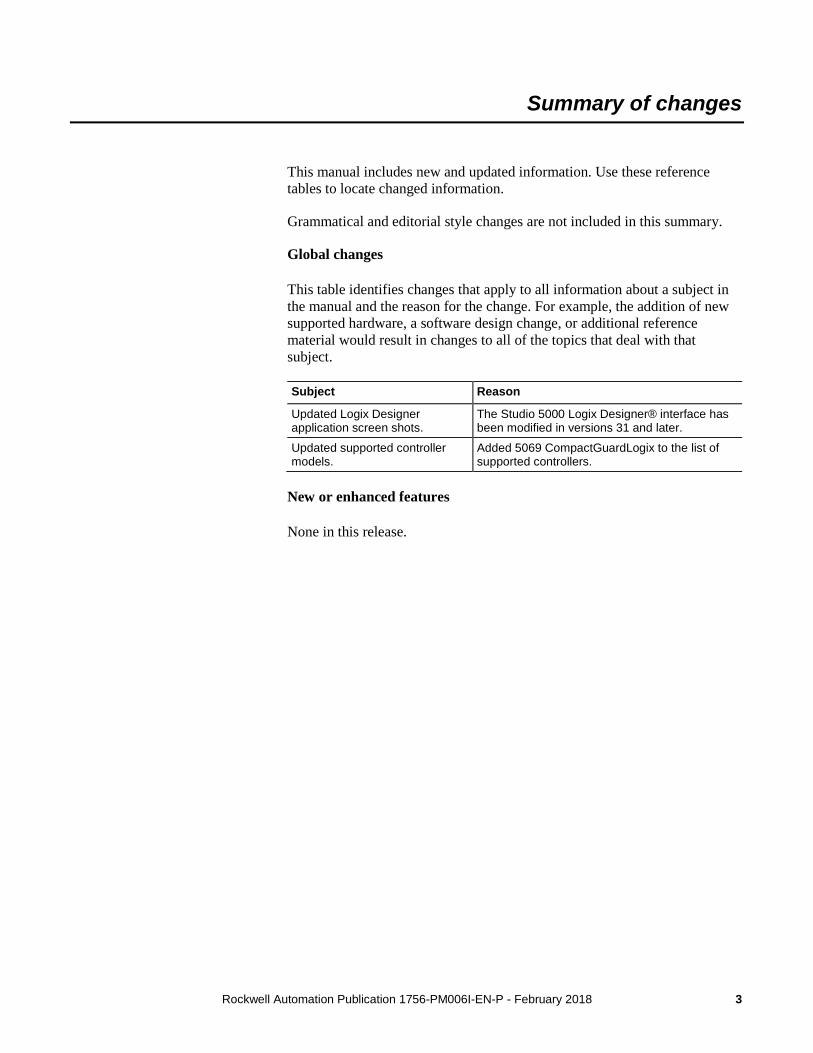
This table identifies changes that apply to all information about a subject in the manual and the reason for the change. For example, the addition of new supported hardware, a software design change, or additional reference material would result in changes to all of the topics that deal with that subject.
Subject Reason
Updated Logix Designer application screen shots.
The Studio 5000 Logix Designer® interface has been modified in versions 31 and later.
Updated supported controller models.
Added 5069 CompactGuardLogix to the list of supported controllers.
New or enhanced features
None in this release.

Rockwell Automation Publication 1756-PM006I-EN-P - February 2018 5
Table of contents
Studio 5000 environment ................................................................................ 9 Additional resources ..................................................................................... 10 Legal notices ................................................................................................. 10
Chapter 1
Introduction ................................................................................................... 13 What is a sequential function chart? ............................................................. 14 Define the tasks ............................................................................................. 17 Choose how to execute the SFC ................................................................... 19 Define the steps of the process ..................................................................... 19
Step guidelines ....................................................................................... 19 SFC_STEP structure .............................................................................. 20
Organize the steps ......................................................................................... 23 Sequence ................................................................................................ 25 Selection branch ..................................................................................... 25 Simultaneous branch .............................................................................. 26 Wire to a previous step ........................................................................... 27
Add actions for each step .............................................................................. 28 How do you want to use the action?....................................................... 28 Use a non-Boolean action ...................................................................... 28 Use a Boolean action .............................................................................. 29 SFC_ACTION structure ......................................................................... 30
Describe each action in pseudocode ............................................................. 31 Choose a qualifier for an action .................................................................... 32 Define the transition conditions .................................................................... 33
Transition tag ......................................................................................... 34 How do you want to program the transition? ......................................... 34 Use a BOOL expression ......................................................................... 35 Call a subroutine in a transition .............................................................. 35
Transition after a specified time ................................................................... 36 Turn off a device at the end of a step ............................................................ 38
Choose a last scan option ....................................................................... 39 Use the Don’t Scan option ..................................................................... 40 Use the programmatic reset option ......................................................... 41 Use the automatic reset option ............................................................... 43
Keep something on from step-to-step ........................................................... 45 How do you want to control the device? ................................................ 45 Use a simultaneous branch ..................................................................... 45 Store and reset an action ......................................................................... 46 Use one large step .................................................................................. 47
End the SFC .................................................................................................. 48 Use a stop element.................................................................................. 48 Restart (reset) the SFC ........................................................................... 49 SFC_STOP structure .............................................................................. 50
Nest an SFC .................................................................................................. 50 Pass parameters ...................................................................................... 52
Preface
Design a sequential function chart
Table of contents
6 Rockwell Automation Publication 1756-PM006I-EN-P - February 2018
Configure when to return to the OS/JSR ...................................................... 52 Pause or reset an SFC ................................................................................... 53 Execution diagrams ...................................................................................... 53
Chapter 2
Introduction ................................................................................................... 57 Add and manually connect elements ...................................................... 57 Add and automatically connect elements ............................................... 58 Drag elements ......................................................................................... 58
Create a simultaneous branch ....................................................................... 58 Start a simultaneous branch .................................................................... 58 End a simultaneous branch ..................................................................... 59
Create a selection branch .............................................................................. 60 Start a selection branch .......................................................................... 60 End a selection branch ............................................................................ 61
Set the priorities of a selection branch .......................................................... 61 Connect a wire to the step ............................................................................. 63 Hide a wire .................................................................................................... 64 Configure a step ............................................................................................ 64
Assign the preset time for a step ............................................................ 64 Configure alarms for a step .................................................................... 65 Use an expression to calculate a time ..................................................... 65
Program a transition ...................................................................................... 66 Enter a BOOL expression ...................................................................... 66 Call a subroutine when programming a transition ................................. 67
Add an action ................................................................................................ 67 Configure an action ....................................................................................... 67
Change the qualifier of an action ........................................................... 67 Calculate a preset time at runtime .......................................................... 68 Mark an action as a BOOLean action .................................................... 69
Program an action ......................................................................................... 69 Enter structured text ............................................................................... 69 Call a subroutine in an action ................................................................. 70
Assign the execution order of actions ........................................................... 70 Document an SFC ......................................................................................... 71
Language switching................................................................................ 71 Add structured text comments ................................................................ 72 Add a tag description.............................................................................. 73 Add a text box ........................................................................................ 73 Show or hide text boxes or tag descriptions ........................................... 74 Hide an individual tag description.......................................................... 74
Configure the execution of the SFC ............................................................. 75 Verify the routine .......................................................................................... 75 Edit an SFC online ........................................................................................ 76
Maintain active SFC step ....................................................................... 76
Program a sequential function chart
Table of contents
Rockwell Automation Publication 1756-PM006I-EN-P - February 2018 7
Chapter 3
Introduction ................................................................................................... 77 Precautions .................................................................................................... 77 Enable forces ................................................................................................ 77 Disable or remove a force ............................................................................. 78 Check force status ......................................................................................... 78
Force LED .............................................................................................. 79 GSV instruction ...................................................................................... 80
Step through a transition or a force of a path ................................................ 80 When to use an SFC force ............................................................................ 81
Force a transition .................................................................................... 81 Force a simultaneous path ...................................................................... 83
Add an SFC force ......................................................................................... 84 Remove or disable forces .............................................................................. 85
Disable all SFC forces ............................................................................ 85 Remove all SFC forces ........................................................................... 85
Force steps
Index

Rockwell Automation Publication 1756-PM006I-EN-P - February 2018 9
Preface
This manual shows how to design and program Sequential Function Charts (SFCs) for Logix 5000 controllers to execute. This manual is one of a set of related manuals that show common procedures for programming and operating Logix 5000™ controllers.
For a complete list of common procedures manuals, refer to the Logix 5000 Controllers Common Procedures Programming Manual , publication 1756-PM001.
The term Logix 5000 controller refers to any controller that is based on the Logix 5000 operating system.
The Studio 5000 Automation Engineering & Design Environment® combines engineering and design elements into a common environment. The first element is the Studio 5000 Logix Designer® application. The Logix Designer application is the rebranding of RSLogix 5000® software and will continue to be the product to program Logix 5000™ controllers for discrete, process, batch, motion, safety, and drive-based solutions.
The Studio 5000® environment is the foundation for the future of Rockwell Automation® engineering design tools and capabilities. The Studio 5000 environment is the one place for design engineers to develop all elements of their control system.
Studio 5000 environment
Preface
10 Rockwell Automation Publication 1756-PM006I-EN-P - February 2018
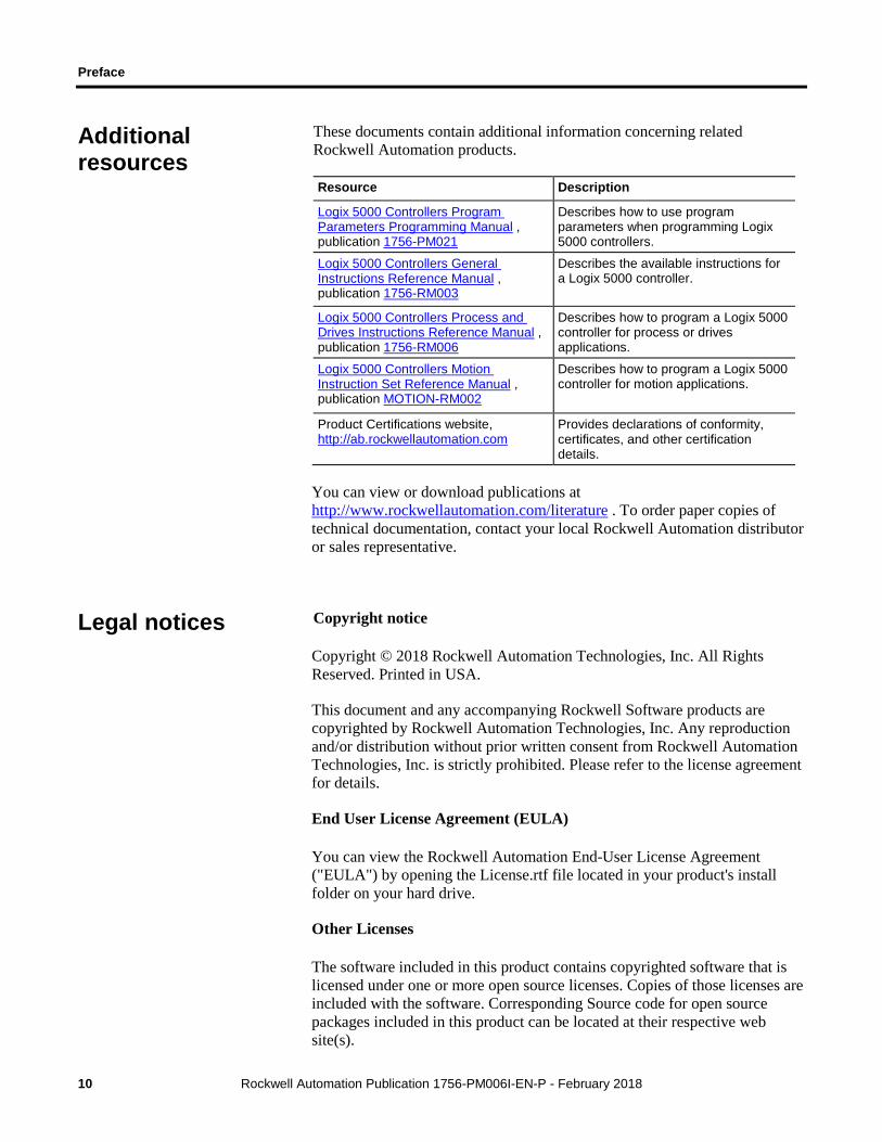
These documents contain additional information concerning related Rockwell Automation products.
Resource Description
Logix 5000 Controllers Program Parameters Programming Manual , publication 1756-PM021
Describes how to use program parameters when programming Logix 5000 controllers.
Logix 5000 Controllers General Instructions Reference Manual , publication 1756-RM003
Describes the available instructions for a Logix 5000 controller.
Logix 5000 Controllers Process and Drives Instructions Reference Manual , publication 1756-RM006
Describes how to program a Logix 5000 controller for process or drives applications.
Logix 5000 Controllers Motion Instruction Set Reference Manual , publication MOTION-RM002
Describes how to program a Logix 5000 controller for motion applications.
Product Certifications website, http://ab.rockwellautomation.com
Provides declarations of conformity, certificates, and other certification details.
You can view or download publications at http://www.rockwellautomation.com/literature . To order paper copies of technical documentation, contact your local Rockwell Automation distributor or sales representative.
Copyright notice
Copyright © 2018 Rockwell Automation Technologies, Inc. All Rights Reserved. Printed in USA.
This document and any accompanying Rockwell Software products are copyrighted by Rockwell Automation Technologies, Inc. Any reproduction and/or distribution without prior written consent from Rockwell Automation Technologies, Inc. is strictly prohibited. Please refer to the license agreement for details.
End User License Agreement (EULA)
You can view the Rockwell Automation End-User License Agreement ("EULA") by opening the License.rtf file located in your product's install folder on your hard drive.
Other Licenses
The software included in this product contains copyrighted software that is licensed under one or more open source licenses. Copies of those licenses are included with the software. Corresponding Source code for open source packages included in this product can be located at their respective web site(s).
Additional resources
Legal notices
Preface
Rockwell Automation Publication 1756-PM006I-EN-P - February 2018 11
You may alternately obtain complete Corresponding Source code by contacting Rockwell Automation via our Contact form on the Rockwell Automation website: http://www.rockwellautomation.com/global/about-us/contact/contact.page . Please include "Open Source" as part of the request text.
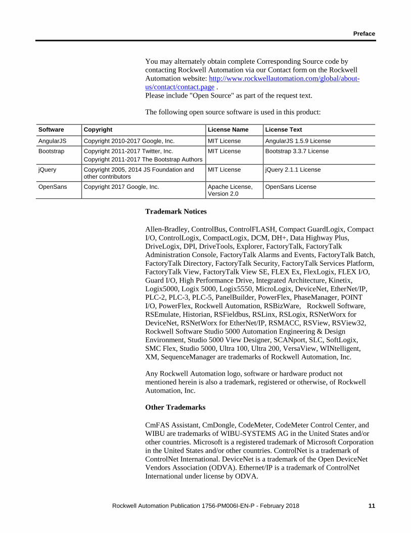
The following open source software is used in this product:
Software Copyright License Name License Text
AngularJS Copyright 2010-2017 Google, Inc. MIT License AngularJS 1.5.9 License
Bootstrap Copyright 2011-2017 Twitter, Inc. Copyright 2011-2017 The Bootstrap Authors
MIT License Bootstrap 3.3.7 License
jQuery Copyright 2005, 2014 JS Foundation and other contributors
MIT License jQuery 2.1.1 License
OpenSans Copyright 2017 Google, Inc. Apache License, Version 2.0
OpenSans License
Trademark Notices
Allen-Bradley, ControlBus, ControlFLASH, Compact GuardLogix, Compact I/O, ControlLogix, CompactLogix, DCM, DH+, Data Highway Plus, DriveLogix, DPI, DriveTools, Explorer, FactoryTalk, FactoryTalk Administration Console, FactoryTalk Alarms and Events, FactoryTalk Batch, FactoryTalk Directory, FactoryTalk Security, FactoryTalk Services Platform, FactoryTalk View, FactoryTalk View SE, FLEX Ex, FlexLogix, FLEX I/O, Guard I/O, High Performance Drive, Integrated Architecture, Kinetix, Logix5000, Logix 5000, Logix5550, MicroLogix, DeviceNet, EtherNet/IP, PLC-2, PLC-3, PLC-5, PanelBuilder, PowerFlex, PhaseManager, POINT I/O, PowerFlex, Rockwell Automation, RSBizWare, Rockwell Software, RSEmulate, Historian, RSFieldbus, RSLinx, RSLogix, RSNetWorx for DeviceNet, RSNetWorx for EtherNet/IP, RSMACC, RSView, RSView32, Rockwell Software Studio 5000 Automation Engineering & Design Environment, Studio 5000 View Designer, SCANport, SLC, SoftLogix, SMC Flex, Studio 5000, Ultra 100, Ultra 200, VersaView, WINtelligent, XM, SequenceManager are trademarks of Rockwell Automation, Inc.
Any Rockwell Automation logo, software or hardware product not mentioned herein is also a trademark, registered or otherwise, of Rockwell Automation, Inc.
Other Trademarks
CmFAS Assistant, CmDongle, CodeMeter, CodeMeter Control Center, and WIBU are trademarks of WIBU-SYSTEMS AG in the United States and/or other countries. Microsoft is a registered trademark of Microsoft Corporation in the United States and/or other countries. ControlNet is a trademark of ControlNet International. DeviceNet is a trademark of the Open DeviceNet Vendors Association (ODVA). Ethernet/IP is a trademark of ControlNet International under license by ODVA.
Preface
12 Rockwell Automation Publication 1756-PM006I-EN-P - February 2018
All other trademarks are the property of their respective holders and are hereby acknowledged.
Warranty
This product is warranted in accordance with the product license. The product’s performance may be affected by system configuration, the application being performed, operator control, maintenance, and other related factors. Rockwell Automation is not responsible for these intervening factors. The instructions in this document do not cover all the details or variations in the equipment, procedure, or process described, nor do they provide directions for meeting every possible contingency during installation, operation, or maintenance. This product’s implementation may vary among users.
This document is current as of the time of release of the product; however, the accompanying software may have changed since the release. Rockwell Automation, Inc. reserves the right to change any information contained in this document or the software at any time without prior notice. It is your responsibility to obtain the most current information available from Rockwell when installing or using this product.
Environmental compliance
Rockwell Automation maintains current product environmental information on its website at http://www.rockwellautomation.com/rockwellautomation/about-us/sustainability-ethics/product-environmental-compliance.page
Contact Rockwell Automation
Customer Support Telephone — 1.440.646.3434
Online Support — http://www.rockwellautomation.com/support/
Rockwell Automation Publication 1756-PM006I-EN-P - February 2018 13
Chapter 1
Design a sequential function chart
A sequential function chart (SFC) is similar to a flowchart of your process. It defines the steps or states through which your system progresses. It helps you do the following:
• Organize the functional specification for your system.
• Program and control your system as a series of steps and transitions.
By using an SFC to specify your process, you gain these advantages.
• Since an SFC is a graphical representation of your process, it is easier to organize and read than a textual version.
• Add notes that clarify steps or capture important information for use later on.
• Print the SFC to share the information with other individuals.
• Since Logix 5000 controllers support SFCs, you do not have to enter the specification a second time. You are programming your system as you specify it.
By using an SFC to program your process, you gain these advantages.
• Graphical division of processes into its major logic pieces (steps)
• Faster repeated execution of individual pieces of your logic
• Simpler screen display
• Reduced time to design and debug your program
• Faster and easier troubleshooting
• Direct access to the point in the logic where a machine faulted
• Easy updates and enhancements
Introduction
Chapter 1 Design a sequential function chart
14 Rockwell Automation Publication 1756-PM006I-EN-P - February 2018
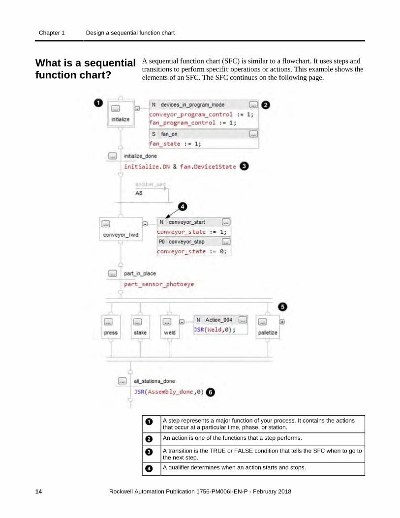
A sequential function chart (SFC) is similar to a flowchart. It uses steps and transitions to perform specific operations or actions. This example shows the elements of an SFC. The SFC continues on the following page.
A step represents a major function of your process. It contains the actions that occur at a particular time, phase, or station.
An action is one of the functions that a step performs.
A transition is the TRUE or FALSE condition that tells the SFC when to go to the next step.
A qualifier determines when an action starts and stops.
What is a sequential function chart?

Design a sequential function chart Chapter 1
Rockwell Automation Publication 1756-PM006I-EN-P - February 2018 15
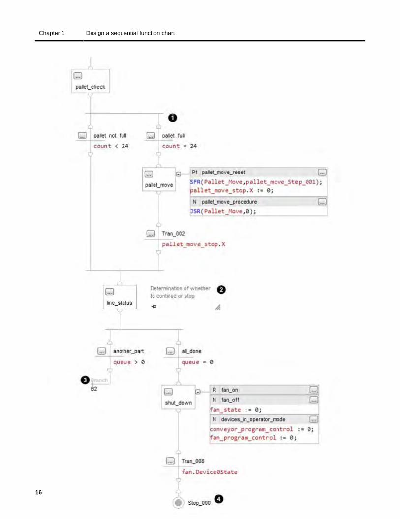
A simultaneous branch executes more than 1 step at the same time.
JSR instruction calls a subroutine.
Chapter 1 Design a sequential function chart
16 Rockwell Automation Publication 1756-PM006I-EN-P - February 2018
Design a sequential function chart Chapter 1
Rockwell Automation Publication 1756-PM006I-EN-P - February 2018 17
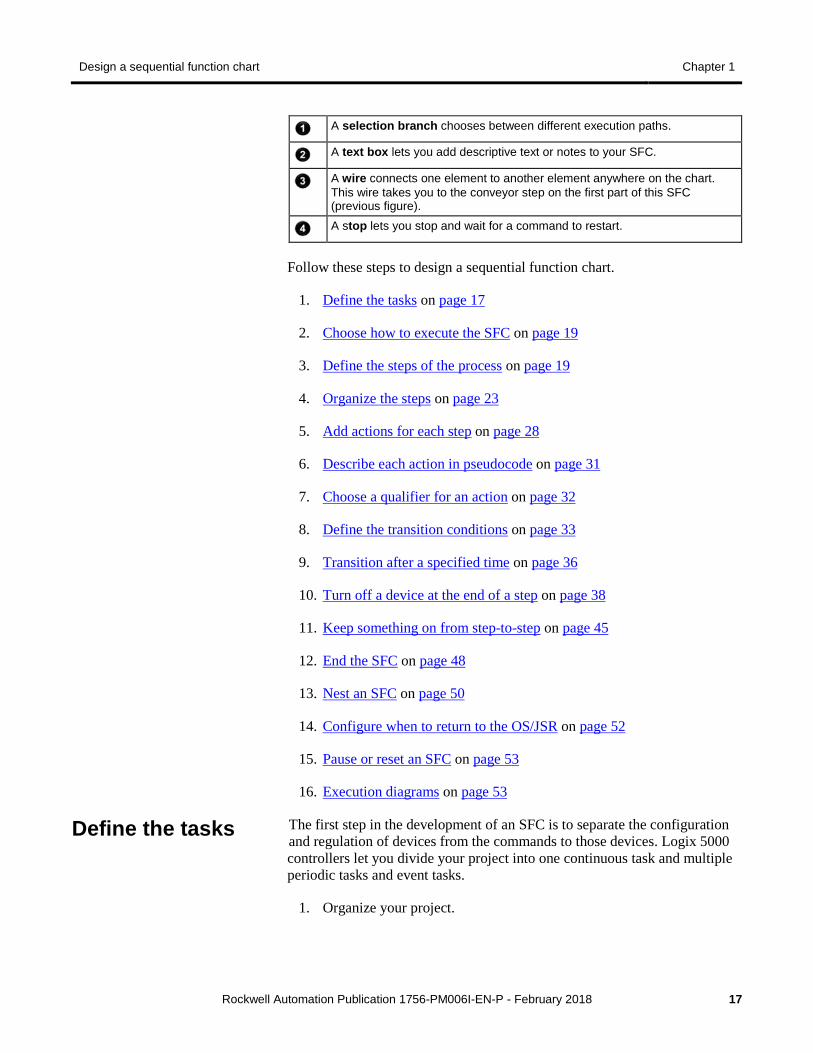
A selection branch chooses between different execution paths.
A text box lets you add descriptive text or notes to your SFC.
A wire connects one element to another element anywhere on the chart. This wire takes you to the conveyor step on the first part of this SFC (previous figure).
A stop lets you stop and wait for a command to restart.
Follow these steps to design a sequential function chart.
1. Define the tasks on page 17
2. Choose how to execute the SFC on page 19
3. Define the steps of the process on page 19
4. Organize the steps on page 23
5. Add actions for each step on page 28
6. Describe each action in pseudocode on page 31
7. Choose a qualifier for an action on page 32
8. Define the transition conditions on page 33
9. Transition after a specified time on page 36
10. Turn off a device at the end of a step on page 38
11. Keep something on from step-to-step on page 45
12. End the SFC on page 48
13. Nest an SFC on page 50
14. Configure when to return to the OS/JSR on page 52
15. Pause or reset an SFC on page 53
16. Execution diagrams on page 53
The first step in the development of an SFC is to separate the configuration and regulation of devices from the commands to those devices. Logix 5000 controllers let you divide your project into one continuous task and multiple periodic tasks and event tasks.
1. Organize your project.
Define the tasks
Chapter 1 Design a sequential function chart
18 Rockwell Automation Publication 1756-PM006I-EN-P - February 2018
These functions Go into this type of task
• Configure and regulate devices Periodic task
• Command a device to a specific state • Sequence the execution of your
process
SFC in the continuous task
2. For those functions that go in a periodic task, group the functions according to similar update rates. Create a periodic task for each update rate.
For example, 2-state devices may require faster updates than PID loops. Use separate periodic tasks for each.
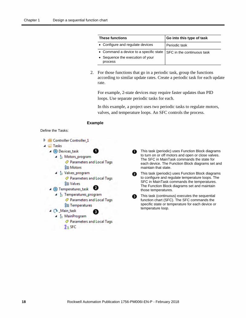
In this example, a project uses two periodic tasks to regulate motors, valves, and temperature loops. An SFC controls the process.
Example
Define the Tasks:
This task (periodic) uses Function Block diagrams to turn on or off motors and open or close valves. The SFC in MainTask commands the state for each device. The Function Block diagrams set and maintain that state.
This task (periodic) uses Function Block diagrams to configure and regulate temperature loops. The SFC in MainTask commands the temperatures. The Function Block diagrams set and maintain those temperatures.
This task (continuous) executes the sequential function chart (SFC). The SFC commands the specific state or temperature for each device or temperature loop.
Design a sequential function chart Chapter 1
Rockwell Automation Publication 1756-PM006I-EN-P - February 2018 19
To execute an SFC, either configure it as the main routine for a program or call it as a subroutine.
If Then
• The SFC is the only routine in the program
• The SFC calls all the other routines of the program
Configure the SFC as the main routine for the program.
• The program requires other routines to execute independent of the SFC
• The SFC uses Boolean actions
1. Configure another routine as the main routine for the program.
2. Use the main routine to call the SFC as a subroutine.
If the SFC uses Boolean actions, then other logic must run independent of the SFC and monitor status bits of the SFC.
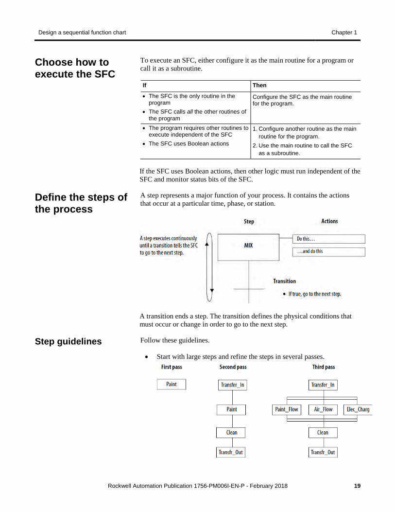
A step represents a major function of your process. It contains the actions that occur at a particular time, phase, or station.
A transition ends a step. The transition defines the physical conditions that must occur or change in order to go to the next step.
Follow these guidelines.
• Start with large steps and refine the steps in several passes.
Choose how to execute the SFC
Define the steps of the process
Step guidelines
Chapter 1 Design a sequential function chart
20 Rockwell Automation Publication 1756-PM006I-EN-P - February 2018
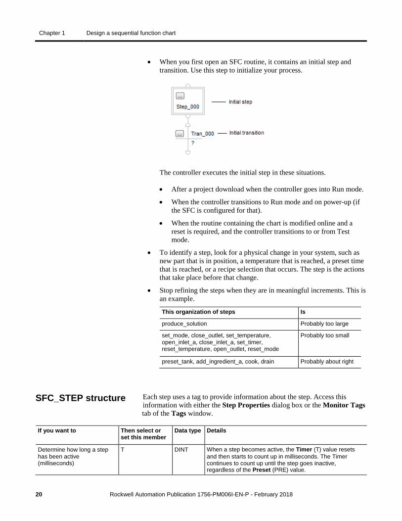
• When you first open an SFC routine, it contains an initial step and transition. Use this step to initialize your process.
The controller executes the initial step in these situations.
• After a project download when the controller goes into Run mode.
• When the controller transitions to Run mode and on power-up (if the SFC is configured for that).
• When the routine containing the chart is modified online and a reset is required, and the controller transitions to or from Test mode.
• To identify a step, look for a physical change in your system, such as new part that is in position, a temperature that is reached, a preset time that is reached, or a recipe selection that occurs. The step is the actions that take place before that change.
• Stop refining the steps when they are in meaningful increments. This is an example.
This organization of steps Is
produce_solution Probably too large
set_mode, close_outlet, set_temperature, open_inlet_a, close_inlet_a, set_timer, reset_temperature, open_outlet, reset_mode
Probably too small
preset_tank, add_ingredient_a, cook, drain Probably about right
Each step uses a tag to provide information about the step. Access this information with either the Step Properties dialog box or the Monitor Tags tab of the Tags window.
If you want to Then select or set this member
Data type Details
Determine how long a step has been active (milliseconds)
T DINT When a step becomes active, the Timer (T) value resets and then starts to count up in milliseconds. The Timer continues to count up until the step goes inactive, regardless of the Preset (PRE) value.
SFC_STEP structure
Design a sequential function chart Chapter 1
Rockwell Automation Publication 1756-PM006I-EN-P - February 2018 21
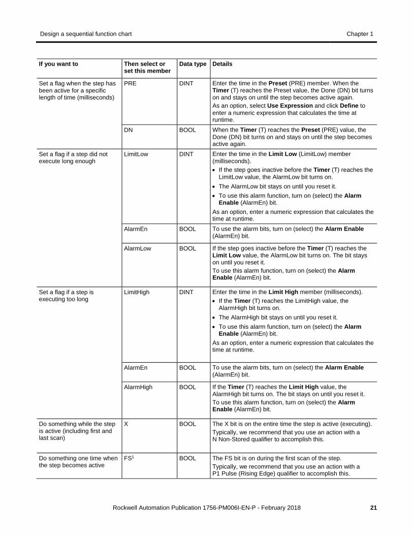
If you want to Then select or set this member
Data type Details
Set a flag when the step has been active for a specific length of time (milliseconds)
PRE DINT Enter the time in the Preset (PRE) member. When the Timer (T) reaches the Preset value, the Done (DN) bit turns on and stays on until the step becomes active again. As an option, select Use Expression and click Define to enter a numeric expression that calculates the time at runtime.
DN BOOL When the Timer (T) reaches the Preset (PRE) value, the Done (DN) bit turns on and stays on until the step becomes active again.
Set a flag if a step did not execute long enough
LimitLow DINT Enter the time in the Limit Low (LimitLow) member (milliseconds). • If the step goes inactive before the Timer (T) reaches the
LimitLow value, the AlarmLow bit turns on. • The AlarmLow bit stays on until you reset it. • To use this alarm function, turn on (select) the Alarm
Enable (AlarmEn) bit. As an option, enter a numeric expression that calculates the time at runtime.
AlarmEn BOOL To use the alarm bits, turn on (select) the Alarm Enable (AlarmEn) bit.
AlarmLow BOOL If the step goes inactive before the Timer (T) reaches the Limit Low value, the AlarmLow bit turns on. The bit stays on until you reset it. To use this alarm function, turn on (select) the Alarm Enable (AlarmEn) bit.
Set a flag if a step is executing too long
LimitHigh DINT Enter the time in the Limit High member (milliseconds). • If the Timer (T) reaches the LimitHigh value, the
AlarmHigh bit turns on. • The AlarmHigh bit stays on until you reset it. • To use this alarm function, turn on (select) the Alarm
Enable (AlarmEn) bit. As an option, enter a numeric expression that calculates the time at runtime.
AlarmEn BOOL To use the alarm bits, turn on (select) the Alarm Enable (AlarmEn) bit.
AlarmHigh BOOL If the Timer (T) reaches the Limit High value, the AlarmHigh bit turns on. The bit stays on until you reset it. To use this alarm function, turn on (select) the Alarm Enable (AlarmEn) bit.
Do something while the step is active (including first and last scan)
X BOOL The X bit is on the entire time the step is active (executing). Typically, we recommend that you use an action with a N Non-Stored qualifier to accomplish this.
Do something one time when the step becomes active
FS1 BOOL The FS bit is on during the first scan of the step. Typically, we recommend that you use an action with a P1 Pulse (Rising Edge) qualifier to accomplish this.
Chapter 1 Design a sequential function chart
22 Rockwell Automation Publication 1756-PM006I-EN-P - February 2018
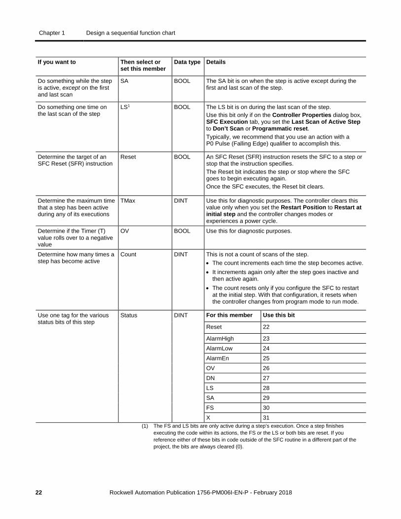
If you want to Then select or set this member
Data type Details
Do something while the step is active, except on the first and last scan
SA BOOL The SA bit is on when the step is active except during the first and last scan of the step.
Do something one time on the last scan of the step
LS1 BOOL The LS bit is on during the last scan of the step. Use this bit only if on the Controller Properties dialog box, SFC Execution tab, you set the Last Scan of Active Step to Don’t Scan or Programmatic reset. Typically, we recommend that you use an action with a P0 Pulse (Falling Edge) qualifier to accomplish this.
Determine the target of an SFC Reset (SFR) instruction
Reset BOOL An SFC Reset (SFR) instruction resets the SFC to a step or stop that the instruction specifies. The Reset bit indicates the step or stop where the SFC goes to begin executing again. Once the SFC executes, the Reset bit clears.
Determine the maximum time that a step has been active during any of its executions
TMax DINT Use this for diagnostic purposes. The controller clears this value only when you set the Restart Position to Restart at initial step and the controller changes modes or experiences a power cycle.
Determine if the Timer (T) value rolls over to a negative value
OV BOOL Use this for diagnostic purposes.
Determine how many times a step has become active
Count DINT This is not a count of scans of the step. • The count increments each time the step becomes active. • It increments again only after the step goes inactive and
then active again. • The count resets only if you configure the SFC to restart
at the initial step. With that configuration, it resets when the controller changes from program mode to run mode.
Use one tag for the various status bits of this step
Status DINT For this member Use this bit
Reset 22
AlarmHigh 23
AlarmLow 24
AlarmEn 25
OV 26
DN 27
LS 28
SA 29
FS 30
X 31 (1) The FS and LS bits are only active during a step’s execution. Once a step finishes
executing the code within its actions, the FS or the LS or both bits are reset. If you reference either of these bits in code outside of the SFC routine in a different part of the project, the bits are always cleared (0).
Design a sequential function chart Chapter 1
Rockwell Automation Publication 1756-PM006I-EN-P - February 2018 23
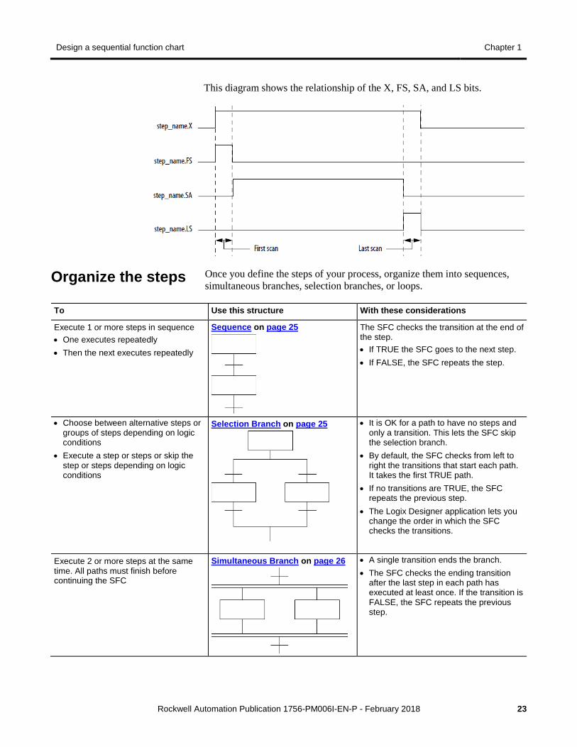
This diagram shows the relationship of the X, FS, SA, and LS bits.
Once you define the steps of your process, organize them into sequences, simultaneous branches, selection branches, or loops.
To Use this structure With these considerations
Execute 1 or more steps in sequence • One executes repeatedly • Then the next executes repeatedly
Sequence on page 25
The SFC checks the transition at the end of the step. • If TRUE the SFC goes to the next step. • If FALSE, the SFC repeats the step.
• Choose between alternative steps or groups of steps depending on logic conditions
• Execute a step or steps or skip the step or steps depending on logic conditions
Selection Branch on page 25
• It is OK for a path to have no steps and only a transition. This lets the SFC skip the selection branch.
• By default, the SFC checks from left to right the transitions that start each path. It takes the first TRUE path.
• If no transitions are TRUE, the SFC repeats the previous step.
• The Logix Designer application lets you change the order in which the SFC checks the transitions.
Execute 2 or more steps at the same time. All paths must finish before continuing the SFC
Simultaneous Branch on page 26
• A single transition ends the branch. • The SFC checks the ending transition
after the last step in each path has executed at least once. If the transition is FALSE, the SFC repeats the previous step.
Organize the steps
Chapter 1 Design a sequential function chart
24 Rockwell Automation Publication 1756-PM006I-EN-P - February 2018
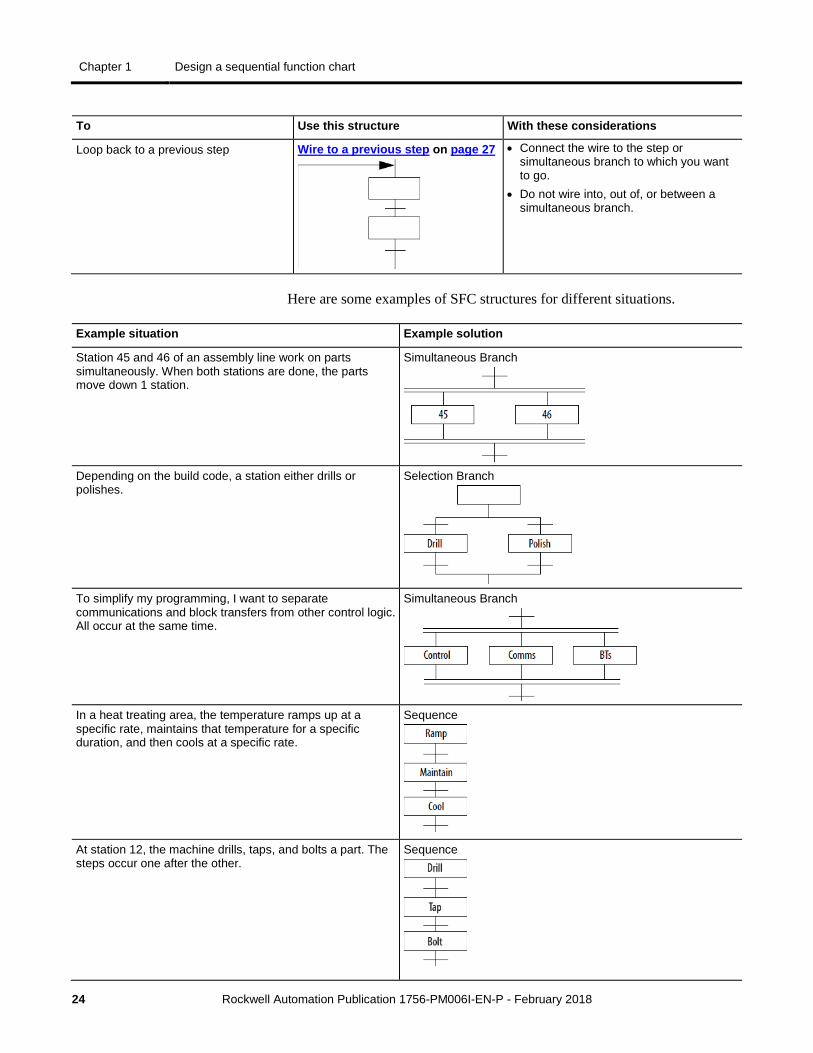
To Use this structure With these considerations
Loop back to a previous step Wire to a previous step on page 27
• Connect the wire to the step or simultaneous branch to which you want to go.
• Do not wire into, out of, or between a simultaneous branch.
Here are some examples of SFC structures for different situations.
Example situation Example solution
Station 45 and 46 of an assembly line work on parts simultaneously. When both stations are done, the parts move down 1 station.
Simultaneous Branch
Depending on the build code, a station either drills or polishes.
Selection Branch
To simplify my programming, I want to separate communications and block transfers from other control logic. All occur at the same time.
Simultaneous Branch
In a heat treating area, the temperature ramps up at a specific rate, maintains that temperature for a specific duration, and then cools at a specific rate.
Sequence
At station 12, the machine drills, taps, and bolts a part. The steps occur one after the other.
Sequence
Design a sequential function chart Chapter 1
Rockwell Automation Publication 1756-PM006I-EN-P - February 2018 25
Example situation Example solution
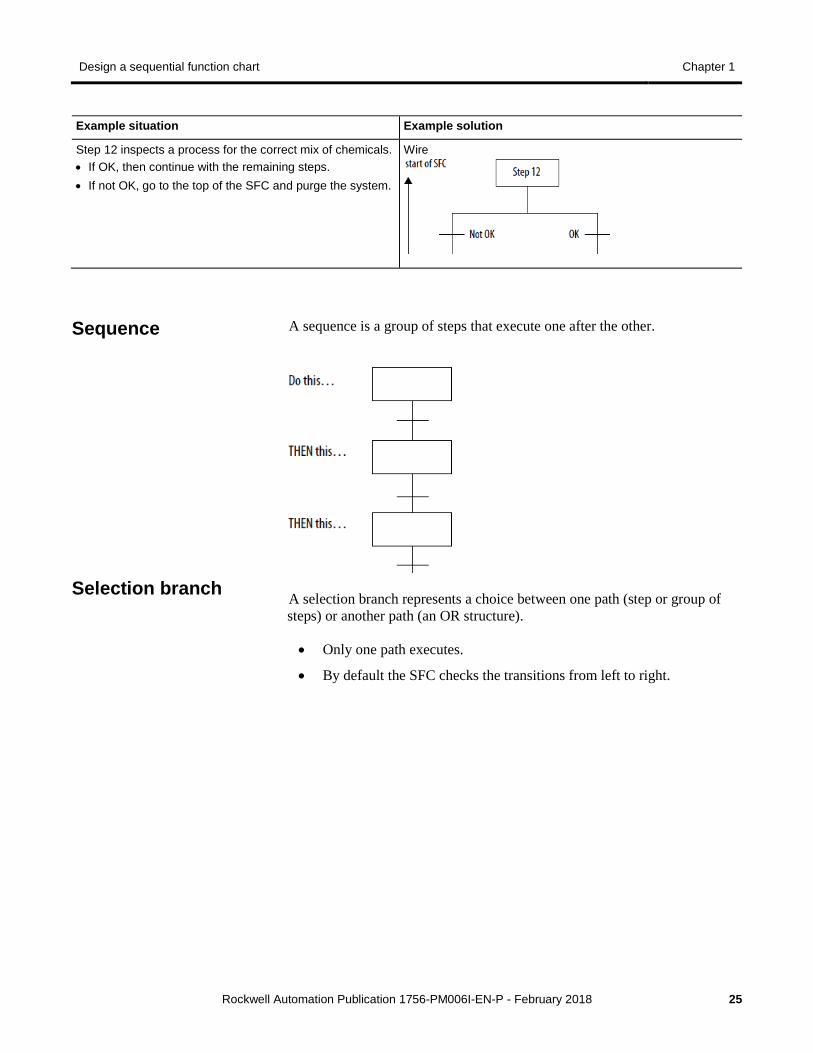
Step 12 inspects a process for the correct mix of chemicals. • If OK, then continue with the remaining steps. • If not OK, go to the top of the SFC and purge the system.
Wire
A sequence is a group of steps that execute one after the other.
A selection branch represents a choice between one path (step or group of steps) or another path (an OR structure).
• Only one path executes.
• By default the SFC checks the transitions from left to right.
Sequence
Selection branch
Chapter 1 Design a sequential function chart
26 Rockwell Automation Publication 1756-PM006I-EN-P - February 2018
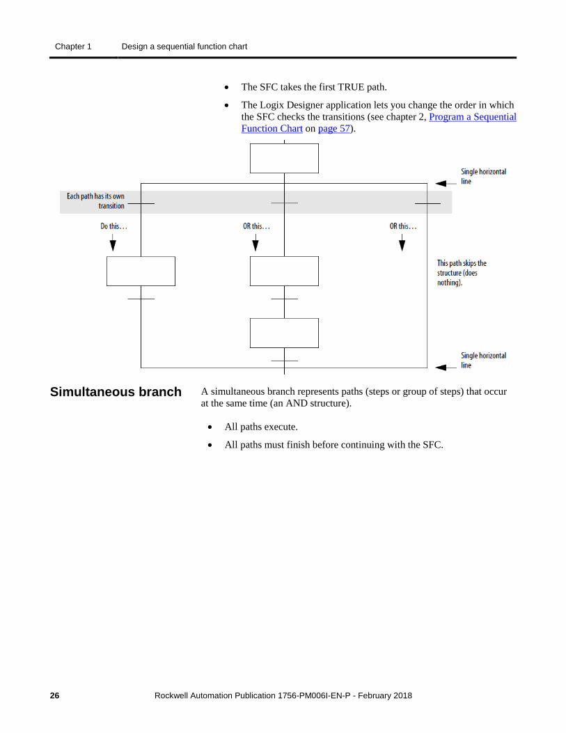
• The SFC takes the first TRUE path.
• The Logix Designer application lets you change the order in which the SFC checks the transitions (see chapter 2, Program a Sequential Function Chart on page 57).
A simultaneous branch represents paths (steps or group of steps) that occur at the same time (an AND structure).
• All paths execute.
• All paths must finish before continuing with the SFC.
Simultaneous branch
Design a sequential function chart Chapter 1
Rockwell Automation Publication 1756-PM006I-EN-P - February 2018 27
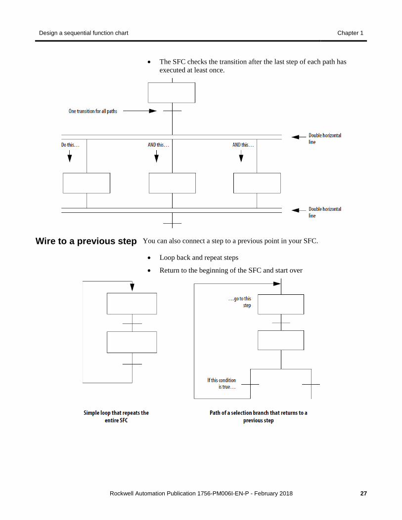
• The SFC checks the transition after the last step of each path has executed at least once.
You can also connect a step to a previous point in your SFC.
• Loop back and repeat steps
• Return to the beginning of the SFC and start over
Wire to a previous step
Chapter 1 Design a sequential function chart
28 Rockwell Automation Publication 1756-PM006I-EN-P - February 2018
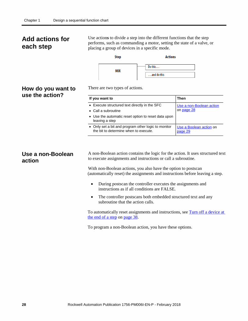
Use actions to divide a step into the different functions that the step performs, such as commanding a motor, setting the state of a valve, or placing a group of devices in a specific mode.
There are two types of actions.
If you want to Then
• Execute structured text directly in the SFC • Call a subroutine • Use the automatic reset option to reset data upon
leaving a step
Use a non-Boolean action on page 28
• Only set a bit and program other logic to monitor the bit to determine when to execute.
Use a Boolean action on page 29
A non-Boolean action contains the logic for the action. It uses structured text to execute assignments and instructions or call a subroutine.
With non-Boolean actions, you also have the option to postscan (automatically reset) the assignments and instructions before leaving a step.
• During postscan the controller executes the assignments and instructions as if all conditions are FALSE.
• The controller postscans both embedded structured text and any subroutine that the action calls.
To automatically reset assignments and instructions, see Turn off a device at the end of a step on page 38.
To program a non-Boolean action, you have these options.
Add actions for each step
How do you want to use the action?
Use a non-Boolean action
Design a sequential function chart Chapter 1
Rockwell Automation Publication 1756-PM006I-EN-P - February 2018 29
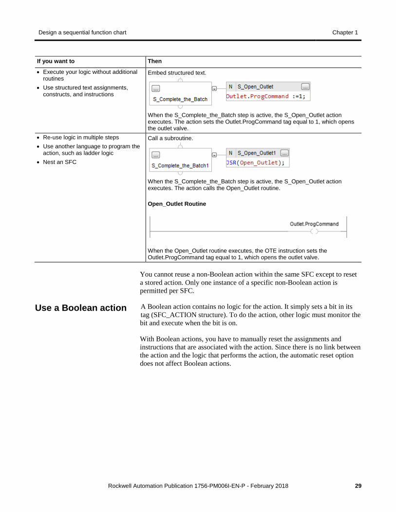
If you want to Then
• Execute your logic without additional routines
• Use structured text assignments, constructs, and instructions
Embed structured text.
When the S_Complete_the_Batch step is active, the S_Open_Outlet action executes. The action sets the Outlet.ProgCommand tag equal to 1, which opens the outlet valve.
• Re-use logic in multiple steps • Use another language to program the
action, such as ladder logic • Nest an SFC
Call a subroutine.
When the S_Complete_the_Batch step is active, the S_Open_Outlet action executes. The action calls the Open_Outlet routine. Open_Outlet Routine
When the Open_Outlet routine executes, the OTE instruction sets the Outlet.ProgCommand tag equal to 1, which opens the outlet valve.
You cannot reuse a non-Boolean action within the same SFC except to reset a stored action. Only one instance of a specific non-Boolean action is permitted per SFC.
A Boolean action contains no logic for the action. It simply sets a bit in its tag (SFC_ACTION structure). To do the action, other logic must monitor the bit and execute when the bit is on.
With Boolean actions, you have to manually reset the assignments and instructions that are associated with the action. Since there is no link between the action and the logic that performs the action, the automatic reset option does not affect Boolean actions.
Use a Boolean action
Chapter 1 Design a sequential function chart
30 Rockwell Automation Publication 1756-PM006I-EN-P - February 2018
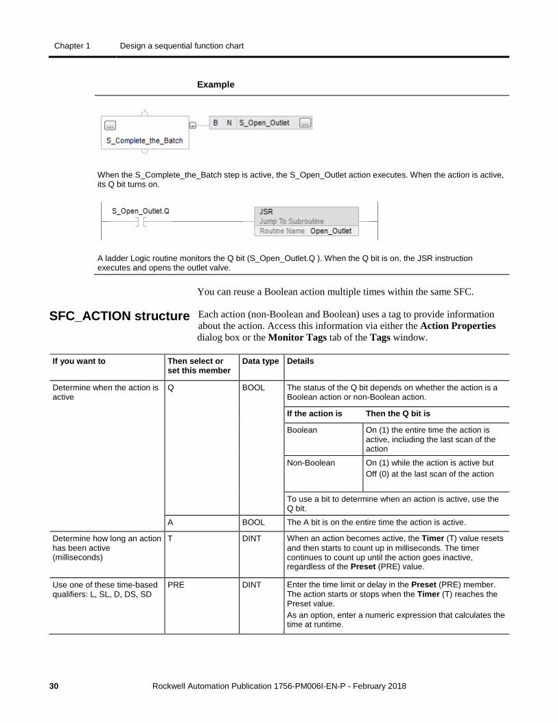
Example
When the S_Complete_the_Batch step is active, the S_Open_Outlet action executes. When the action is active, its Q bit turns on.
A ladder Logic routine monitors the Q bit (S_Open_Outlet.Q ). When the Q bit is on, the JSR instruction executes and opens the outlet valve.
You can reuse a Boolean action multiple times within the same SFC.
Each action (non-Boolean and Boolean) uses a tag to provide information about the action. Access this information via either the Action Properties dialog box or the Monitor Tags tab of the Tags window.
If you want to Then select or set this member
Data type Details
Determine when the action is active
Q BOOL The status of the Q bit depends on whether the action is a Boolean action or non-Boolean action.
If the action is Then the Q bit is
Boolean On (1) the entire time the action is active, including the last scan of the action
Non-Boolean On (1) while the action is active but Off (0) at the last scan of the action
To use a bit to determine when an action is active, use the Q bit.
A BOOL The A bit is on the entire time the action is active.
Determine how long an action has been active (milliseconds)
T DINT When an action becomes active, the Timer (T) value resets and then starts to count up in milliseconds. The timer continues to count up until the action goes inactive, regardless of the Preset (PRE) value.
Use one of these time-based qualifiers: L, SL, D, DS, SD
PRE DINT Enter the time limit or delay in the Preset (PRE) member. The action starts or stops when the Timer (T) reaches the Preset value. As an option, enter a numeric expression that calculates the time at runtime.
SFC_ACTION structure

Design a sequential function chart Chapter 1
Rockwell Automation Publication 1756-PM006I-EN-P - February 2018 31
If you want to Then select or set this member
Data type Details
Determine how many times an action has become active
Count DINT This is not a count of scans of the action. • The count increments each time the action becomes
active. • It increments again only after the action goes inactive and
then active again. • The count resets only if you configure the SFC to restart
at the initial step. With that configuration, it resets when the controller changes from program mode to run mode.
Use one tag for the various status bits of this action
Status DINT For this member Use this bit
Q 30
A 31
To organize the logic for an action, first you describe the action in pseudocode.
• Use a series of short statements that describe what should happen.
• Use terms or symbols, such as: if, then, otherwise, until, and, or, =, >, <.
• Sequence the statements in the order that they should execute.
• If necessary, name the conditions to check first (the "when to act" first) and then the action to take second (the "what to do" second).
Enter the pseudocode into the body of the action.
• Refine the pseudocode so it executes as structured text.
• Use the pseudocode to design your logic and leave the pseudocode as comments. Since all structured text comments download to the controller, your pseudocode is always available as documentation for the action.
To convert the pseudocode to structured text comments, add these comment symbols.
For a comment Use one of these formats
On a single line //comment
That spans more than one line (*start of comment . . . end of comment*) /*start of comment . . . end of comment*/
Describe each action in pseudocode
Chapter 1 Design a sequential function chart
32 Rockwell Automation Publication 1756-PM006I-EN-P - February 2018
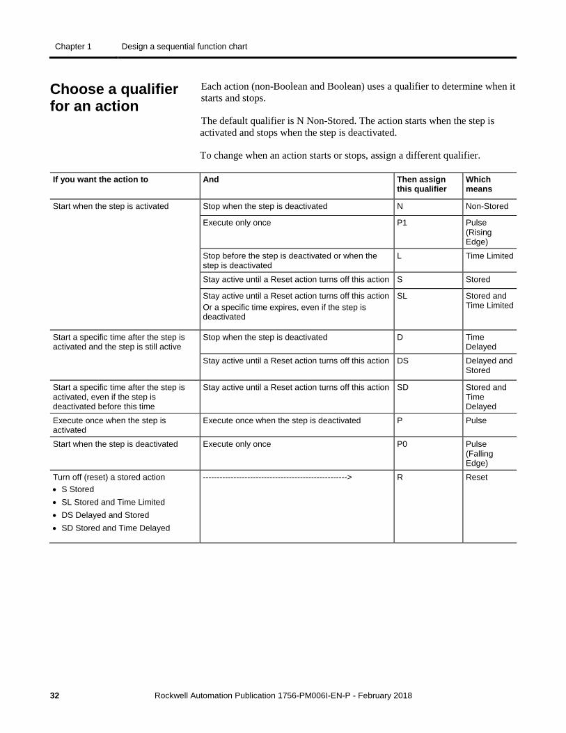
Each action (non-Boolean and Boolean) uses a qualifier to determine when it starts and stops.
The default qualifier is N Non-Stored. The action starts when the step is activated and stops when the step is deactivated.
To change when an action starts or stops, assign a different qualifier.
If you want the action to And Then assign this qualifier
Which means
Start when the step is activated Stop when the step is deactivated N Non-Stored
Execute only once P1 Pulse (Rising Edge)
Stop before the step is deactivated or when the step is deactivated
L Time Limited
Stay active until a Reset action turns off this action S Stored
Stay active until a Reset action turns off this action Or a specific time expires, even if the step is deactivated
SL Stored and Time Limited
Start a specific time after the step is activated and the step is still active
Stop when the step is deactivated D Time Delayed
Stay active until a Reset action turns off this action DS Delayed and Stored
Start a specific time after the step is activated, even if the step is deactivated before this time
Stay active until a Reset action turns off this action SD Stored and Time Delayed
Execute once when the step is activated
Execute once when the step is deactivated P Pulse
Start when the step is deactivated Execute only once P0 Pulse (Falling Edge)
Turn off (reset) a stored action • S Stored • SL Stored and Time Limited • DS Delayed and Stored • SD Stored and Time Delayed
----------------------------------------------------> R Reset
Choose a qualifier for an action
Design a sequential function chart Chapter 1
Rockwell Automation Publication 1756-PM006I-EN-P - February 2018 33
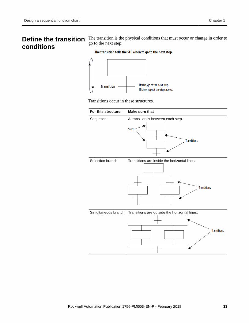
The transition is the physical conditions that must occur or change in order to go to the next step.
Transitions occur in these structures.
For this structure Make sure that
Sequence A transition is between each step.
Selection branch Transitions are inside the horizontal lines.
Simultaneous branch Transitions are outside the horizontal lines.
Define the transition conditions
Chapter 1 Design a sequential function chart
34 Rockwell Automation Publication 1756-PM006I-EN-P - February 2018
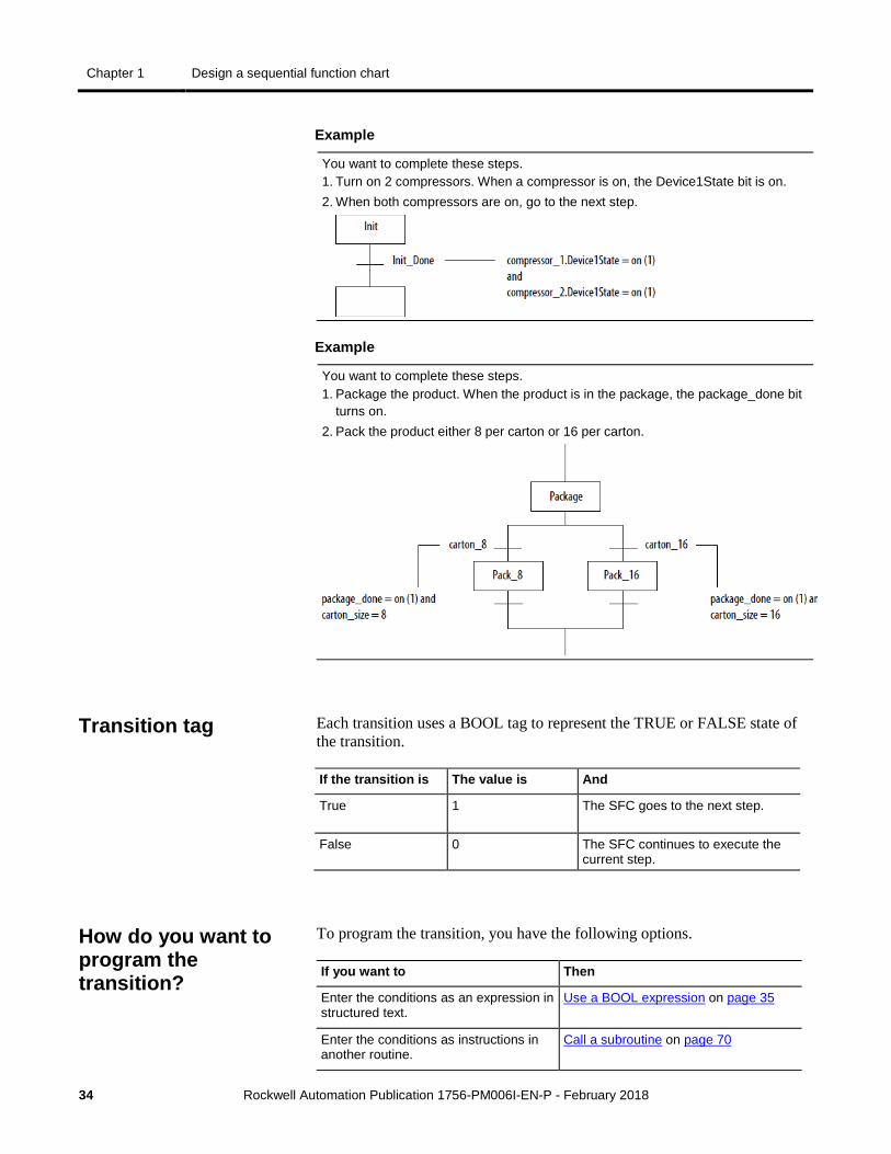
Example
You want to complete these steps. 1. Turn on 2 compressors. When a compressor is on, the Device1State bit is on. 2. When both compressors are on, go to the next step.
Example
You want to complete these steps. 1. Package the product. When the product is in the package, the package_done bit
turns on. 2. Pack the product either 8 per carton or 16 per carton.
Each transition uses a BOOL tag to represent the TRUE or FALSE state of the transition.
If the transition is The value is And
True 1 The SFC goes to the next step.
False 0 The SFC continues to execute the current step.
To program the transition, you have the following options.
If you want to Then
Enter the conditions as an expression in structured text.
Use a BOOL expression on page 35
Enter the conditions as instructions in another routine.
Call a subroutine on page 70
Transition tag
How do you want to program the transition?
Design a sequential function chart Chapter 1
Rockwell Automation Publication 1756-PM006I-EN-P - February 2018 35
If you want to Then
Use the same logic for multiple transitions.
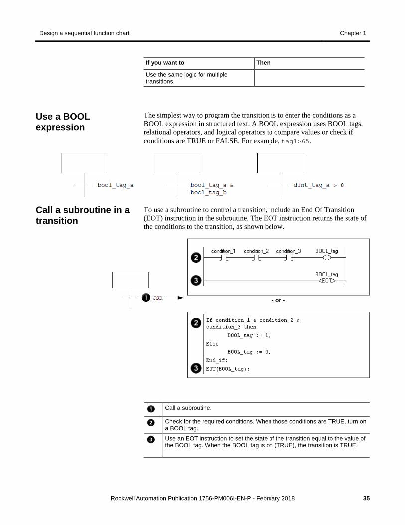
The simplest way to program the transition is to enter the conditions as a BOOL expression in structured text. A BOOL expression uses BOOL tags, relational operators, and logical operators to compare values or check if conditions are TRUE or FALSE. For example, tag1>65.
To use a subroutine to control a transition, include an End Of Transition (EOT) instruction in the subroutine. The EOT instruction returns the state of the conditions to the transition, as shown below.
- or -
Call a subroutine.
Check for the required conditions. When those conditions are TRUE, turn on a BOOL tag.
Use an EOT instruction to set the state of the transition equal to the value of the BOOL tag. When the BOOL tag is on (TRUE), the transition is TRUE.
Use a BOOL expression
Call a subroutine in a transition
Chapter 1 Design a sequential function chart
36 Rockwell Automation Publication 1756-PM006I-EN-P - February 2018
Each step of the SFC includes a millisecond timer that runs whenever the step is active. Use the timer to for these situations.
• Signal when the step has run for the required time and the SFC should go to the next step.
• Signal when the step has run too long and the SFC should go to an error step.
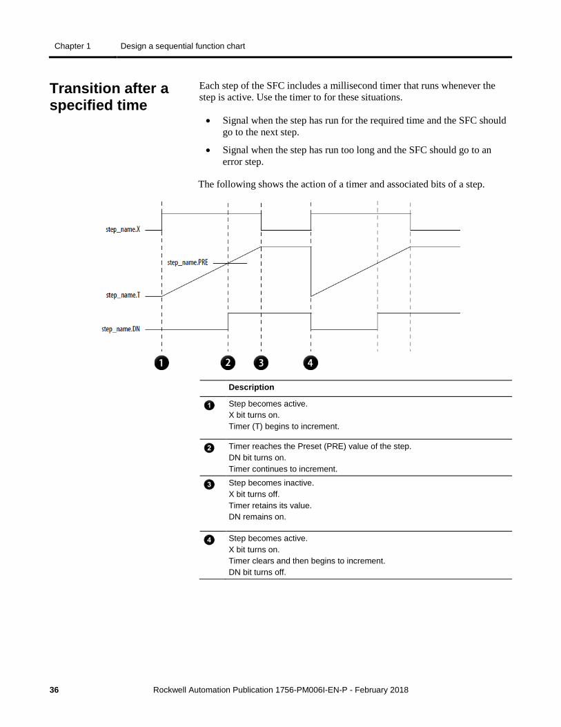
The following shows the action of a timer and associated bits of a step.
Description
Step becomes active. X bit turns on. Timer (T) begins to increment.
Timer reaches the Preset (PRE) value of the step. DN bit turns on. Timer continues to increment.
Step becomes inactive. X bit turns off. Timer retains its value. DN remains on.
Step becomes active. X bit turns on. Timer clears and then begins to increment. DN bit turns off.
Transition after a specified time
Design a sequential function chart Chapter 1
Rockwell Automation Publication 1756-PM006I-EN-P - February 2018 37
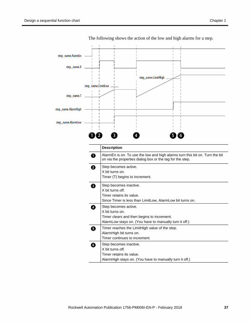
The following shows the action of the low and high alarms for a step.
Description
AlarmEn is on. To use the low and high alarms turn this bit on. Turn the bit on via the properties dialog box or the tag for the step.
Step becomes active. X bit turns on. Timer (T) begins to increment.
Step becomes inactive. X bit turns off. Timer retains its value. Since Timer is less than LimitLow, AlarmLow bit turns on.
Step becomes active. X bit turns on. Timer clears and then begins to increment. AlarmLow stays on. (You have to manually turn it off.)
Timer reaches the LimitHigh value of the step. AlarmHigh bit turns on. Timer continues to increment.
Step becomes inactive. X bit turns off. Timer retains its value. AlarmHigh stays on. (You have to manually turn it off.)
Chapter 1 Design a sequential function chart
38 Rockwell Automation Publication 1756-PM006I-EN-P - February 2018
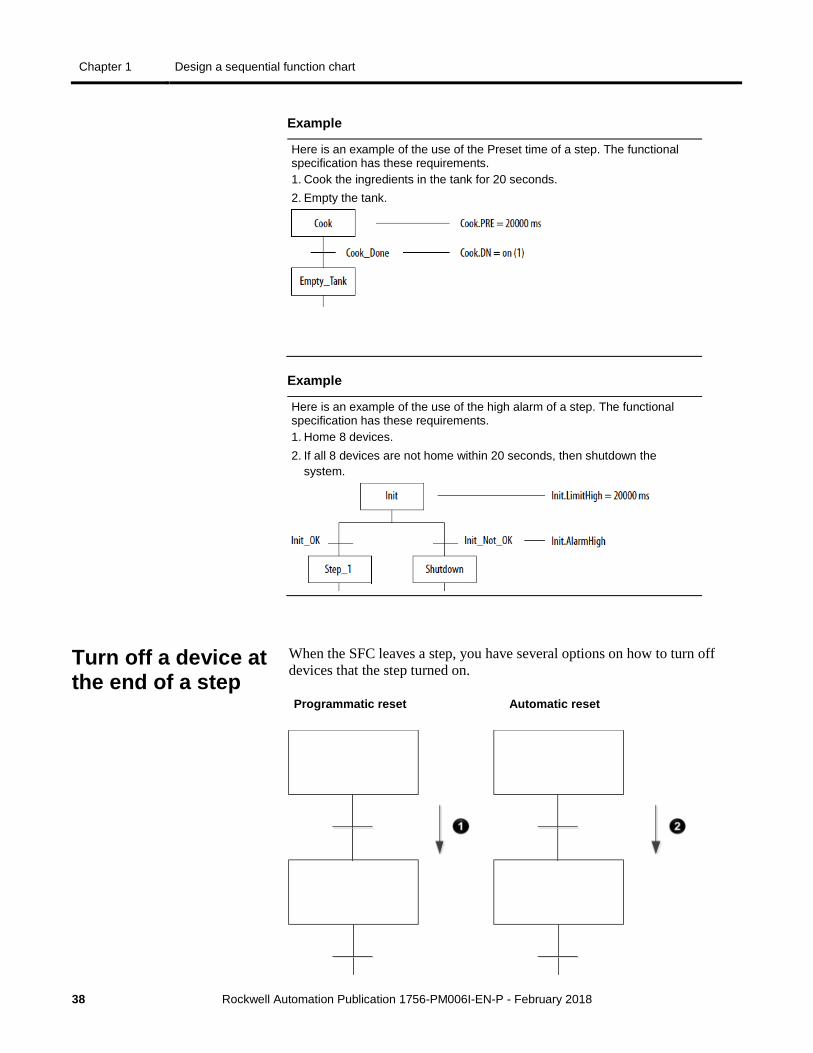
Example
Here is an example of the use of the Preset time of a step. The functional specification has these requirements. 1. Cook the ingredients in the tank for 20 seconds. 2. Empty the tank.
Example
Here is an example of the use of the high alarm of a step. The functional specification has these requirements. 1. Home 8 devices. 2. If all 8 devices are not home within 20 seconds, then shutdown the
system.
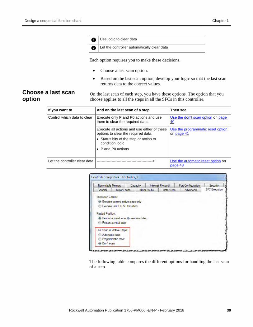
When the SFC leaves a step, you have several options on how to turn off devices that the step turned on.
Programmatic reset Automatic reset
Turn off a device at the end of a step
Design a sequential function chart Chapter 1
Rockwell Automation Publication 1756-PM006I-EN-P - February 2018 39
Use logic to clear data
Let the controller automatically clear data
Each option requires you to make these decisions.
• Choose a last scan option.
• Based on the last scan option, develop your logic so that the last scan returns data to the correct values.
On the last scan of each step, you have these options. The option that you choose applies to all the steps in all the SFCs in this controller.
If you want to And on the last scan of a step Then see
Control which data to clear Execute only P and P0 actions and use them to clear the required data.
Use the don’t scan option on page 40
Execute all actions and use either of these options to clear the required data. • Status bits of the step or action to
condition logic • P and P0 actions
Use the programmatic reset option on page 41
Let the controller clear data ---------------------------------------------> Use the automatic reset option on page 43
The following table compares the different options for handling the last scan of a step.
Choose a last scan option
Chapter 1 Design a sequential function chart
40 Rockwell Automation Publication 1756-PM006I-EN-P - February 2018
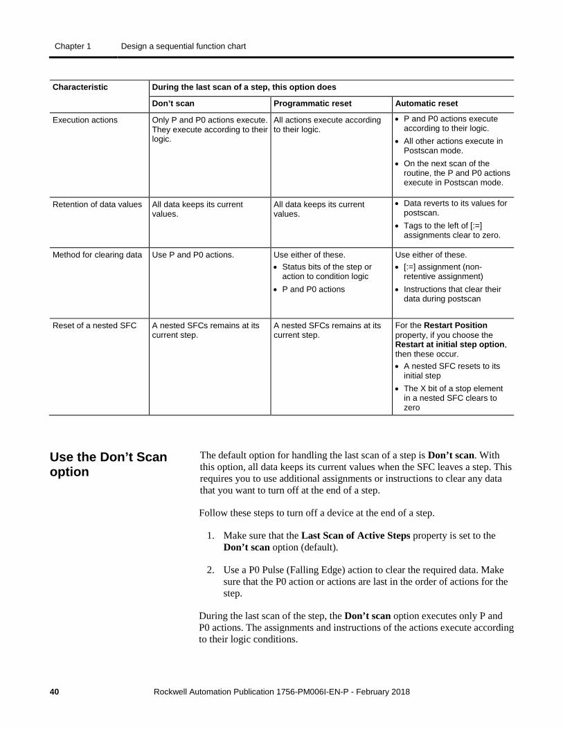
Characteristic During the last scan of a step, this option does
Don’t scan Programmatic reset Automatic reset
Execution actions Only P and P0 actions execute. They execute according to their logic.
All actions execute according to their logic.
• P and P0 actions execute according to their logic.
• All other actions execute in Postscan mode.
• On the next scan of the routine, the P and P0 actions execute in Postscan mode.
Retention of data values All data keeps its current values.
All data keeps its current values.
• Data reverts to its values for postscan.
• Tags to the left of [:=] assignments clear to zero.
Method for clearing data Use P and P0 actions. Use either of these. • Status bits of the step or
action to condition logic • P and P0 actions
Use either of these. • [:=] assignment (non-
retentive assignment) • Instructions that clear their
data during postscan
Reset of a nested SFC A nested SFCs remains at its current step.
A nested SFCs remains at its current step.
For the Restart Position property, if you choose the Restart at initial step option, then these occur. • A nested SFC resets to its
initial step • The X bit of a stop element
in a nested SFC clears to zero
The default option for handling the last scan of a step is Don’t scan. With this option, all data keeps its current values when the SFC leaves a step. This requires you to use additional assignments or instructions to clear any data that you want to turn off at the end of a step.
Follow these steps to turn off a device at the end of a step.
1. Make sure that the Last Scan of Active Steps property is set to the Don’t scan option (default).
2. Use a P0 Pulse (Falling Edge) action to clear the required data. Make sure that the P0 action or actions are last in the order of actions for the step.
During the last scan of the step, the Don’t scan option executes only P and P0 actions. The assignments and instructions of the actions execute according to their logic conditions.
Use the Don’t Scan option
Design a sequential function chart Chapter 1
Rockwell Automation Publication 1756-PM006I-EN-P - February 2018 41
• The controller does not execute a postscan of assignments or instructions.
• When the SFC leaves the step, all data keeps its current values.
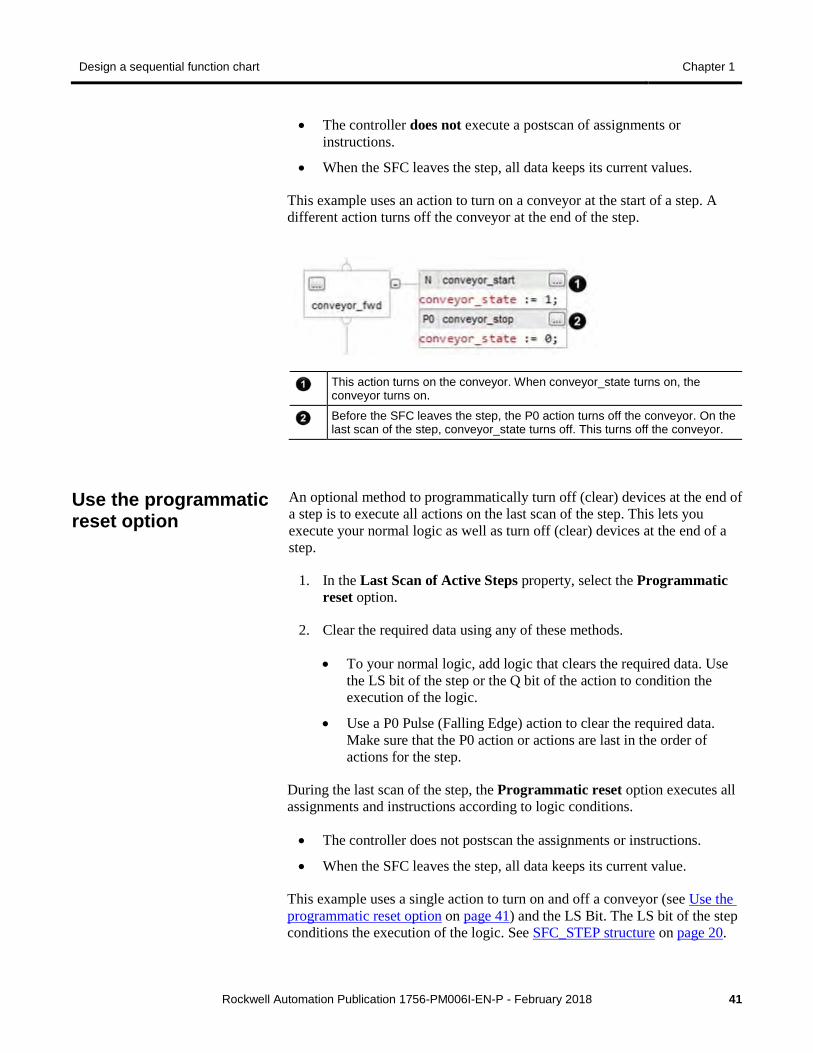
This example uses an action to turn on a conveyor at the start of a step. A different action turns off the conveyor at the end of the step.
This action turns on the conveyor. When conveyor_state turns on, the conveyor turns on.
Before the SFC leaves the step, the P0 action turns off the conveyor. On the last scan of the step, conveyor_state turns off. This turns off the conveyor.
An optional method to programmatically turn off (clear) devices at the end of a step is to execute all actions on the last scan of the step. This lets you execute your normal logic as well as turn off (clear) devices at the end of a step.
1. In the Last Scan of Active Steps property, select the Programmatic reset option.
2. Clear the required data using any of these methods.
• To your normal logic, add logic that clears the required data. Use the LS bit of the step or the Q bit of the action to condition the execution of the logic.
• Use a P0 Pulse (Falling Edge) action to clear the required data. Make sure that the P0 action or actions are last in the order of actions for the step.
During the last scan of the step, the Programmatic reset option executes all assignments and instructions according to logic conditions.
• The controller does not postscan the assignments or instructions.
• When the SFC leaves the step, all data keeps its current value.
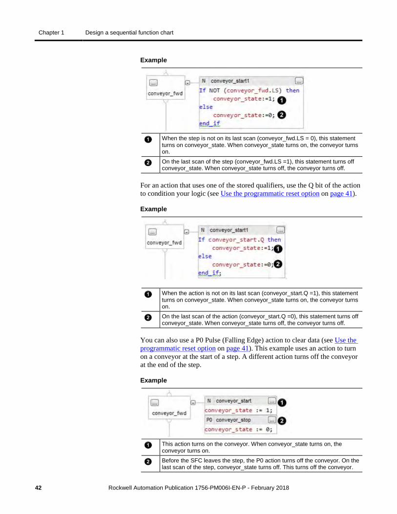
This example uses a single action to turn on and off a conveyor (see Use the programmatic reset option on page 41) and the LS Bit. The LS bit of the step conditions the execution of the logic. See SFC_STEP structure on page 20.
Use the programmatic reset option
Chapter 1 Design a sequential function chart
42 Rockwell Automation Publication 1756-PM006I-EN-P - February 2018
Example
When the step is not on its last scan (conveyor_fwd.LS = 0), this statement turns on conveyor_state. When conveyor_state turns on, the conveyor turns on.
On the last scan of the step (conveyor_fwd.LS =1), this statement turns off conveyor_state. When conveyor_state turns off, the conveyor turns off.
For an action that uses one of the stored qualifiers, use the Q bit of the action to condition your logic (see Use the programmatic reset option on page 41).
Example
When the action is not on its last scan (conveyor_start.Q =1), this statement turns on conveyor_state. When conveyor_state turns on, the conveyor turns on.
On the last scan of the action (conveyor_start.Q =0), this statement turns off conveyor_state. When conveyor_state turns off, the conveyor turns off.
You can also use a P0 Pulse (Falling Edge) action to clear data (see Use the programmatic reset option on page 41). This example uses an action to turn on a conveyor at the start of a step. A different action turns off the conveyor at the end of the step.
Example
This action turns on the conveyor. When conveyor_state turns on, the conveyor turns on.
Before the SFC leaves the step, the P0 action turns off the conveyor. On the last scan of the step, conveyor_state turns off. This turns off the conveyor.
Design a sequential function chart Chapter 1
Rockwell Automation Publication 1756-PM006I-EN-P - February 2018 43
Automatic reset provides a system-defined cleanup of actions (known as postscan) when they are shut down when any of the following occur.
• transition out of the associated step
• reset of a stored action
• reset of an SFC routine
Postscan is similar to prescan in that most instructions are executed as if they are FALSE. Some instructions have specific postscan behavior.
• In RLL, OTE instructions are turned off and non-retentive timers are reset.
• In structured text, the destination of a non-retentive assignment "[:=]" is cleared.
• A JSR instruction invokes its subroutine but parameters are not passed and the logic in the subroutine is executed in postscan mode.
• An Add-On Instruction executes its logic routine in postscan mode and then executes its postscan logic in normal mode (if a postscan routine is configured).
• Any nested SFC (SFC that an action calls as a subroutine) is reset.
Important: The postscan of an action actually occurs when the action goes from active to inactive. Depending on the qualifier of the action, the postscan could occur before or after the last scan of the step.
As a general rule, the postscan executes instructions as if all conditions are FALSE. For example, the Output Energize (OTE) instruction clears its data during postscan.
Follow these steps to automatically turn off (clear) devices at the end of a step.
1. In the Last Scan of Active Steps property, select the Automatic reset option.
2. To turn off a device at the end of the step, control the state of the device with an assignment or instruction.
• [:=] assignment (non-retentive assignment)
• Output Energize (OTE) instruction in a subroutine
Some instructions do not follow the general rule during postscan. For a description of how a specific instruction executes during postscan, see these publications.
Use the automatic reset option
Chapter 1 Design a sequential function chart
44 Rockwell Automation Publication 1756-PM006I-EN-P - February 2018
• Logix 5000 Controllers General Instructions Reference Manual , publication 1756-RM003
• Logix 5000 Controllers Process and Drives Instructions Reference Manual , publication 1756-PM006
• Logix 5000 Controllers Motion Instruction Set Reference Manual , publication MOTION-RM002
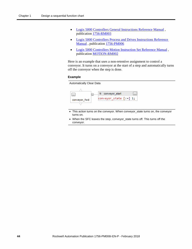
Here is an example that uses a non-retentive assignment to control a conveyor. It turns on a conveyor at the start of a step and automatically turns off the conveyor when the step is done.
Example
Automatically Clear Data
• This action turns on the conveyor. When conveyor_state turns on, the conveyor turns on.
• When the SFC leaves the step, conveyor_state turns off. This turns off the conveyor.
Design a sequential function chart Chapter 1
Rockwell Automation Publication 1756-PM006I-EN-P - February 2018 45
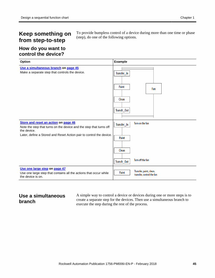
To provide bumpless control of a device during more than one time or phase (step), do one of the following options.
Option Example
Use a simultaneous branch on page 45 Make a separate step that controls the device.
Store and reset an action on page 46 Note the step that turns on the device and the step that turns off the device. Later, define a Stored and Reset Action pair to control the device.
Use one large step on page 47 Use one large step that contains all the actions that occur while the device is on.
A simple way to control a device or devices during one or more steps is to create a separate step for the devices. Then use a simultaneous branch to execute the step during the rest of the process.
Keep something on from step-to-step How do you want to control the device?
Use a simultaneous branch
Chapter 1 Design a sequential function chart
46 Rockwell Automation Publication 1756-PM006I-EN-P - February 2018
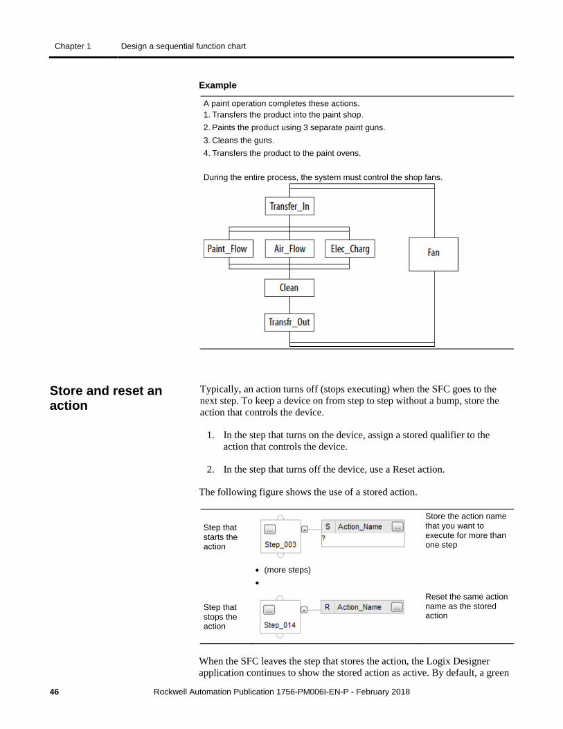
Example
A paint operation completes these actions. 1. Transfers the product into the paint shop. 2. Paints the product using 3 separate paint guns. 3. Cleans the guns. 4. Transfers the product to the paint ovens. During the entire process, the system must control the shop fans.
Typically, an action turns off (stops executing) when the SFC goes to the next step. To keep a device on from step to step without a bump, store the action that controls the device.
1. In the step that turns on the device, assign a stored qualifier to the action that controls the device.
2. In the step that turns off the device, use a Reset action.
The following figure shows the use of a stored action.
Step that starts the action
Store the action name that you want to execute for more than one step
• (more steps) •
Step that stops the action
Reset the same action name as the stored action
When the SFC leaves the step that stores the action, the Logix Designer application continues to show the stored action as active. By default, a green
Store and reset an action
Design a sequential function chart Chapter 1
Rockwell Automation Publication 1756-PM006I-EN-P - February 2018 47
border displays around the action. This lets you know that the SFC is executing the logic of that action.
To use a stored action, follow these guidelines.
• The Reset action only turns off the stored action. It does not automatically turn off the devices of the action. To turn off the device, follow the Reset action with another action that turns off the device. Or use the Automatic reset option described in Use the automatic reset option on page 43.
• Before the SFC reaches a stop element, reset any stored actions that you do not want to execute at the stop. An active stored action remains active even if the SFC reaches a stop.
• Use caution when you jump in between a step that stores an action and a step that resets the action. Once you reset an action, it only starts when you execute the step that stores the action.
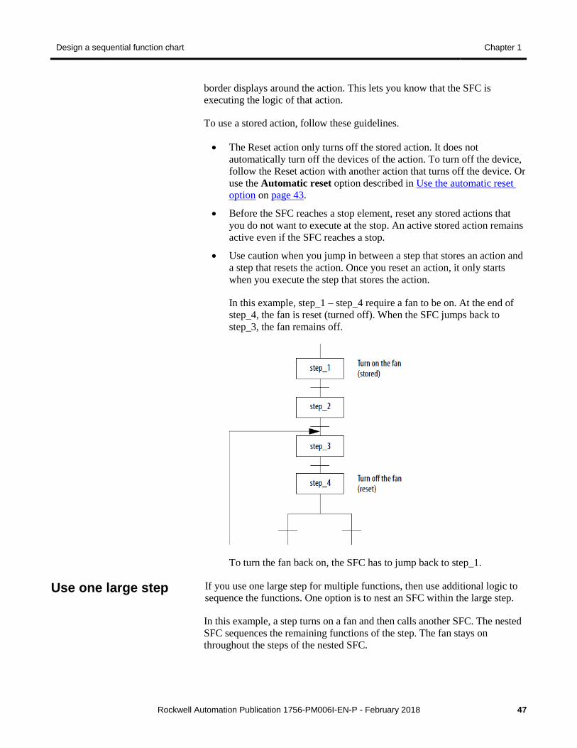
In this example, step_1 – step_4 require a fan to be on. At the end of step_4, the fan is reset (turned off). When the SFC jumps back to step_3, the fan remains off.
To turn the fan back on, the SFC has to jump back to step_1.
If you use one large step for multiple functions, then use additional logic to sequence the functions. One option is to nest an SFC within the large step.
In this example, a step turns on a fan and then calls another SFC. The nested SFC sequences the remaining functions of the step. The fan stays on throughout the steps of the nested SFC.
Use one large step
Chapter 1 Design a sequential function chart
48 Rockwell Automation Publication 1756-PM006I-EN-P - February 2018
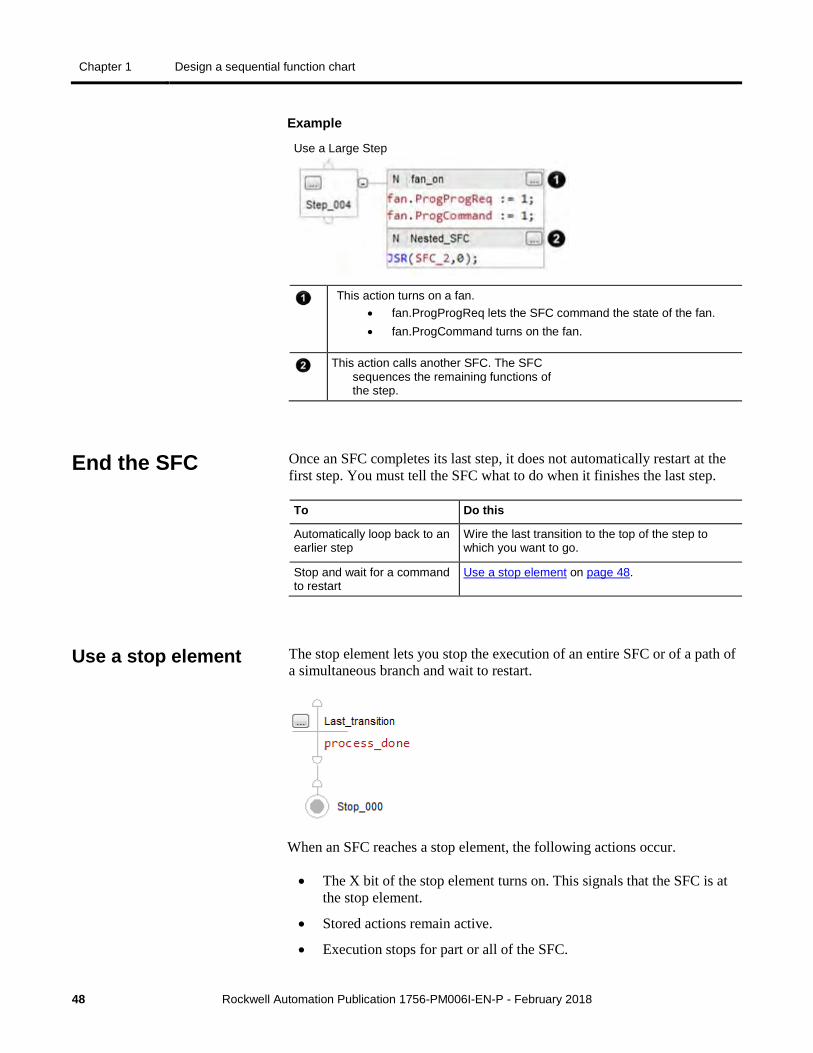
Example
Use a Large Step
This action turns on a fan.
• fan.ProgProgReq lets the SFC command the state of the fan. • fan.ProgCommand turns on the fan.
This action calls another SFC. The SFC sequences the remaining functions of the step.
Once an SFC completes its last step, it does not automatically restart at the first step. You must tell the SFC what to do when it finishes the last step.
To Do this
Automatically loop back to an earlier step
Wire the last transition to the top of the step to which you want to go.
Stop and wait for a command to restart
Use a stop element on page 48.
The stop element lets you stop the execution of an entire SFC or of a path of a simultaneous branch and wait to restart.
When an SFC reaches a stop element, the following actions occur.
• The X bit of the stop element turns on. This signals that the SFC is at the stop element.
• Stored actions remain active.
• Execution stops for part or all of the SFC.
End the SFC
Use a stop element
Design a sequential function chart Chapter 1
Rockwell Automation Publication 1756-PM006I-EN-P - February 2018 49
If the stop element is at the end of a Then
• Sequence • Selection branch
The entire SFC stops
• Path within a simultaneous branch Only that path stops while the rest of the SFC continues to execute.
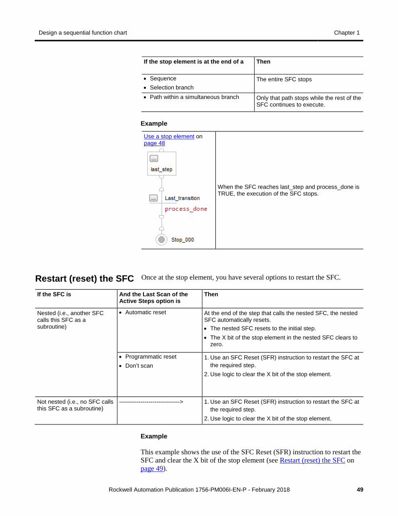
Example
Use a stop element on page 48
When the SFC reaches last_step and process_done is TRUE, the execution of the SFC stops.
Once at the stop element, you have several options to restart the SFC.
If the SFC is And the Last Scan of the Active Steps option is
Then
Nested (i.e., another SFC calls this SFC as a subroutine)
• Automatic reset At the end of the step that calls the nested SFC, the nested SFC automatically resets. • The nested SFC resets to the initial step. • The X bit of the stop element in the nested SFC clears to
zero.
• Programmatic reset • Don’t scan
1. Use an SFC Reset (SFR) instruction to restart the SFC at the required step.
2. Use logic to clear the X bit of the stop element.
Not nested (i.e., no SFC calls this SFC as a subroutine)
-------------------------------> 1. Use an SFC Reset (SFR) instruction to restart the SFC at the required step.
2. Use logic to clear the X bit of the stop element.
Example
This example shows the use of the SFC Reset (SFR) instruction to restart the SFC and clear the X bit of the stop element (see Restart (reset) the SFC on page 49).
Restart (reset) the SFC
Chapter 1 Design a sequential function chart
50 Rockwell Automation Publication 1756-PM006I-EN-P - February 2018
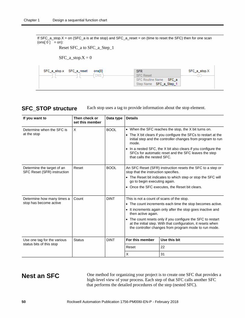
If SFC_a_stop.X = on (SFC_a is at the stop) and SFC_a_reset = on (time to reset the SFC) then for one scan (ons[ 0 ] = on):
Reset SFC_a to SFC_a_Step_1
SFC_a_stop.X = 0
Each stop uses a tag to provide information about the stop element.
If you want to Then check or set this member
Data type Details
Determine when the SFC is at the stop
X BOOL • When the SFC reaches the stop, the X bit turns on. • The X bit clears if you configure the SFCs to restart at the
initial step and the controller changes from program to run mode.
• In a nested SFC, the X bit also clears if you configure the SFCs for automatic reset and the SFC leaves the step that calls the nested SFC.
Determine the target of an SFC Reset (SFR) instruction
Reset BOOL An SFC Reset (SFR) instruction resets the SFC to a step or stop that the instruction specifies. • The Reset bit indicates to which step or stop the SFC will
go to begin executing again. • Once the SFC executes, the Reset bit clears.
Determine how many times a stop has become active
Count DINT This is not a count of scans of the stop. • The count increments each time the stop becomes active. • It increments again only after the stop goes inactive and
then active again. • The count resets only if you configure the SFC to restart
at the initial step. With that configuration, it resets when the controller changes from program mode to run mode.
Use one tag for the various status bits of this stop
Status DINT For this member Use this bit
Reset 22
X 31
One method for organizing your project is to create one SFC that provides a high-level view of your process. Each step of that SFC calls another SFC that performs the detailed procedures of the step (nested SFC).
SFC_STOP structure
Nest an SFC
Design a sequential function chart Chapter 1
Rockwell Automation Publication 1756-PM006I-EN-P - February 2018 51
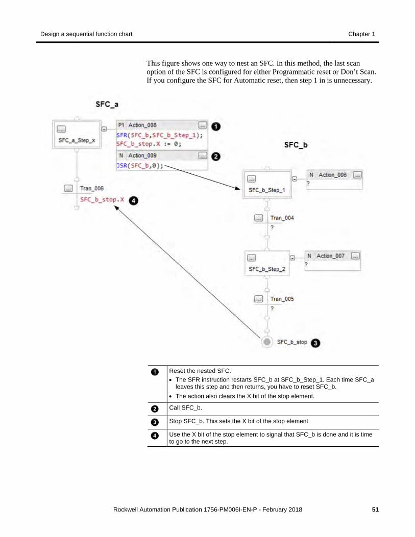
This figure shows one way to nest an SFC. In this method, the last scan option of the SFC is configured for either Programmatic reset or Don’t Scan. If you configure the SFC for Automatic reset, then step 1 in is unnecessary.
Reset the nested SFC. • The SFR instruction restarts SFC_b at SFC_b_Step_1. Each time SFC_a
leaves this step and then returns, you have to reset SFC_b. • The action also clears the X bit of the stop element.
Call SFC_b.
Stop SFC_b. This sets the X bit of the stop element.
Use the X bit of the stop element to signal that SFC_b is done and it is time to go to the next step.
Chapter 1 Design a sequential function chart
52 Rockwell Automation Publication 1756-PM006I-EN-P - February 2018
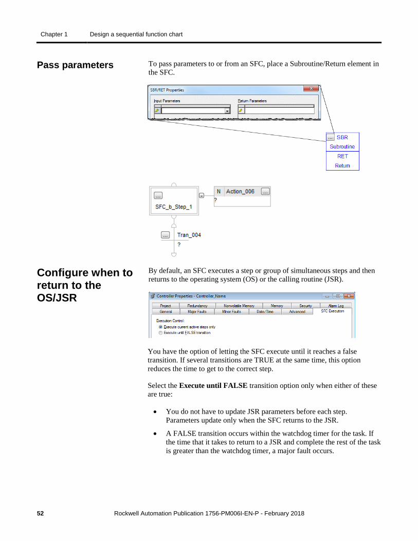
To pass parameters to or from an SFC, place a Subroutine/Return element in the SFC.
By default, an SFC executes a step or group of simultaneous steps and then returns to the operating system (OS) or the calling routine (JSR).
You have the option of letting the SFC execute until it reaches a false transition. If several transitions are TRUE at the same time, this option reduces the time to get to the correct step.
Select the Execute until FALSE transition option only when either of these are true:
• You do not have to update JSR parameters before each step. Parameters update only when the SFC returns to the JSR.
• A FALSE transition occurs within the watchdog timer for the task. If the time that it takes to return to a JSR and complete the rest of the task is greater than the watchdog timer, a major fault occurs.
Pass parameters
Configure when to return to the OS/JSR
Design a sequential function chart Chapter 1
Rockwell Automation Publication 1756-PM006I-EN-P - February 2018 53
Two optional instructions are available that give you further control over the execution of your SFC.
If you want to Then use this instruction
Pause an SFC Pause SFC (SFP)
Reset an SFC to a specific step or stop Reset SFC (SFR)
Both instructions are available in the ladder logic and structured text programming languages.
The following diagrams show the execution of an SFC with different organizations of steps or different selections of execution options.
• Execution of a sequence
• Execution of a simultaneous branch
• Execution of a selection branch
• When parameters enter and exit an SFC
• Options for execution control
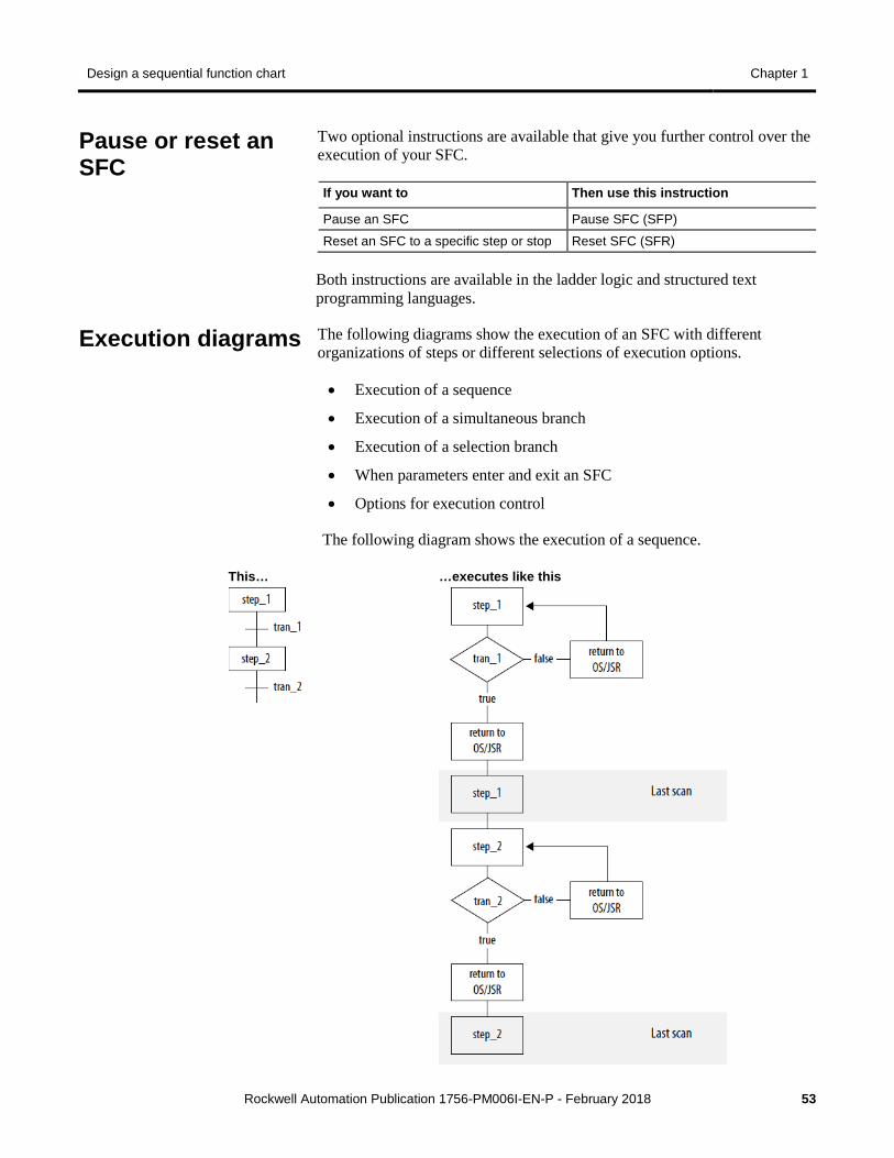
The following diagram shows the execution of a sequence.
This…
…executes like this
Pause or reset an SFC
Execution diagrams
Chapter 1 Design a sequential function chart
54 Rockwell Automation Publication 1756-PM006I-EN-P - February 2018
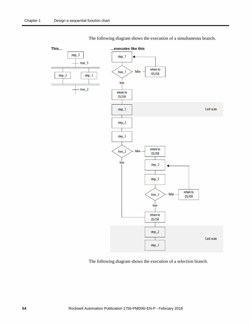
The following diagram shows the execution of a simultaneous branch.
This…
…executes like this
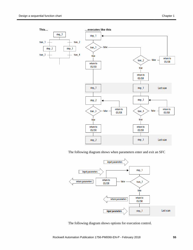
The following diagram shows the execution of a selection branch.
Design a sequential function chart Chapter 1
Rockwell Automation Publication 1756-PM006I-EN-P - February 2018 55
This…
…executes like this
The following diagram shows when parameters enter and exit an SFC
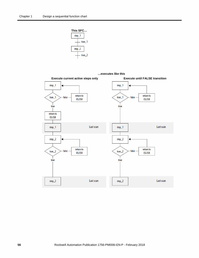
The following diagram shows options for execution control.
Chapter 1 Design a sequential function chart
56 Rockwell Automation Publication 1756-PM006I-EN-P - February 2018
This SFC…
…executes like this Execute current active steps only Execute until FALSE transition
Rockwell Automation Publication 1756-PM006I-EN-P - February 2018 57
Chapter 2
Program a sequential function chart
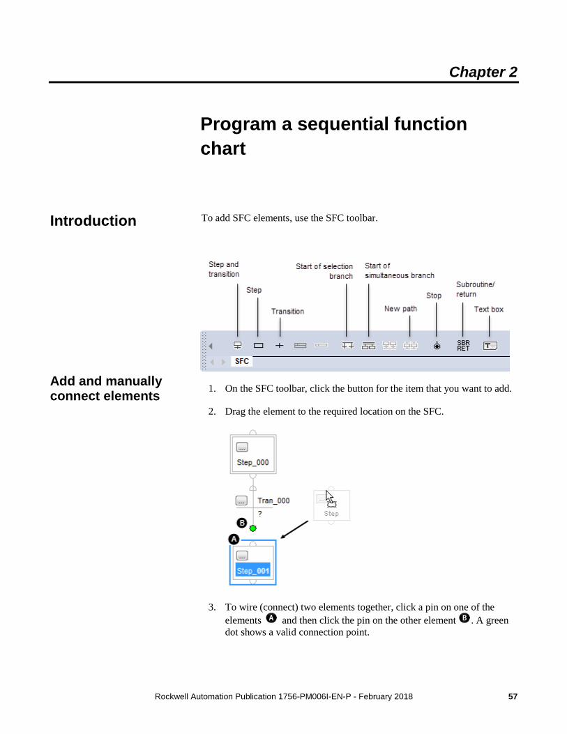
To add SFC elements, use the SFC toolbar.
1. On the SFC toolbar, click the button for the item that you want to add.
2. Drag the element to the required location on the SFC.
3. To wire (connect) two elements together, click a pin on one of the elements and then click the pin on the other element . A green dot shows a valid connection point.
Introduction
Add and manually connect elements
Chapter 2 Program a sequential function chart
58 Rockwell Automation Publication 1756-PM006I-EN-P - February 2018
Important: Use caution when copying and pasting components between different versions of the Logix Designer application. The application only supports pasting to the same version or newer. Pasting to a prior version of the application is not supported. When pasting to a prior version, the paste action may succeed but the results may not be as intended.
1. Click the element to which you want to connect a new element.
2. With the element still selected, click the toolbar button for the next element.
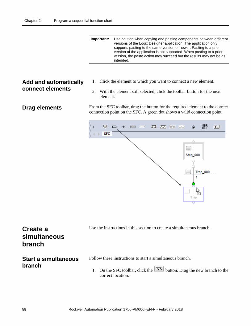
From the SFC toolbar, drag the button for the required element to the correct connection point on the SFC. A green dot shows a valid connection point.
Use the instructions in this section to create a simultaneous branch.
Follow these instructions to start a simultaneous branch.
1. On the SFC toolbar, click the button. Drag the new branch to the correct location.
Add and automatically connect elements
Drag elements
Create a simultaneous branch
Start a simultaneous branch
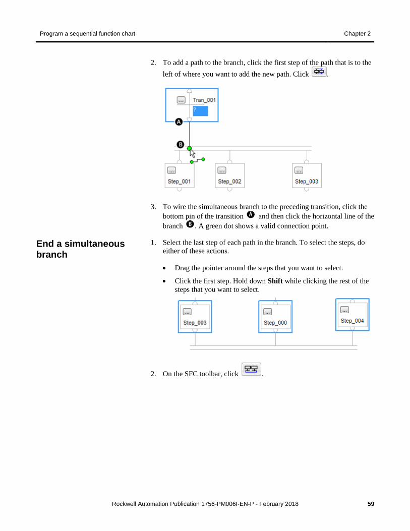
Program a sequential function chart Chapter 2
Rockwell Automation Publication 1756-PM006I-EN-P - February 2018 59
2. To add a path to the branch, click the first step of the path that is to the left of where you want to add the new path. Click .
3. To wire the simultaneous branch to the preceding transition, click the bottom pin of the transition and then click the horizontal line of the branch . A green dot shows a valid connection point.
1. Select the last step of each path in the branch. To select the steps, do either of these actions.
• Drag the pointer around the steps that you want to select.
• Click the first step. Hold down Shift while clicking the rest of the steps that you want to select.
2. On the SFC toolbar, click .
End a simultaneous branch
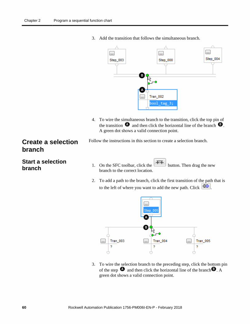
Chapter 2 Program a sequential function chart
60 Rockwell Automation Publication 1756-PM006I-EN-P - February 2018
3. Add the transition that follows the simultaneous branch.
4. To wire the simultaneous branch to the transition, click the top pin of the transition and then click the horizontal line of the branch . A green dot shows a valid connection point.
Follow the instructions in this section to create a selection branch.
1. On the SFC toolbar, click the button. Then drag the new branch to the correct location.
2. To add a path to the branch, click the first transition of the path that is to the left of where you want to add the new path. Click .
3. To wire the selection branch to the preceding step, click the bottom pin of the step and then click the horizontal line of the branch . A green dot shows a valid connection point.
Create a selection branch
Start a selection branch
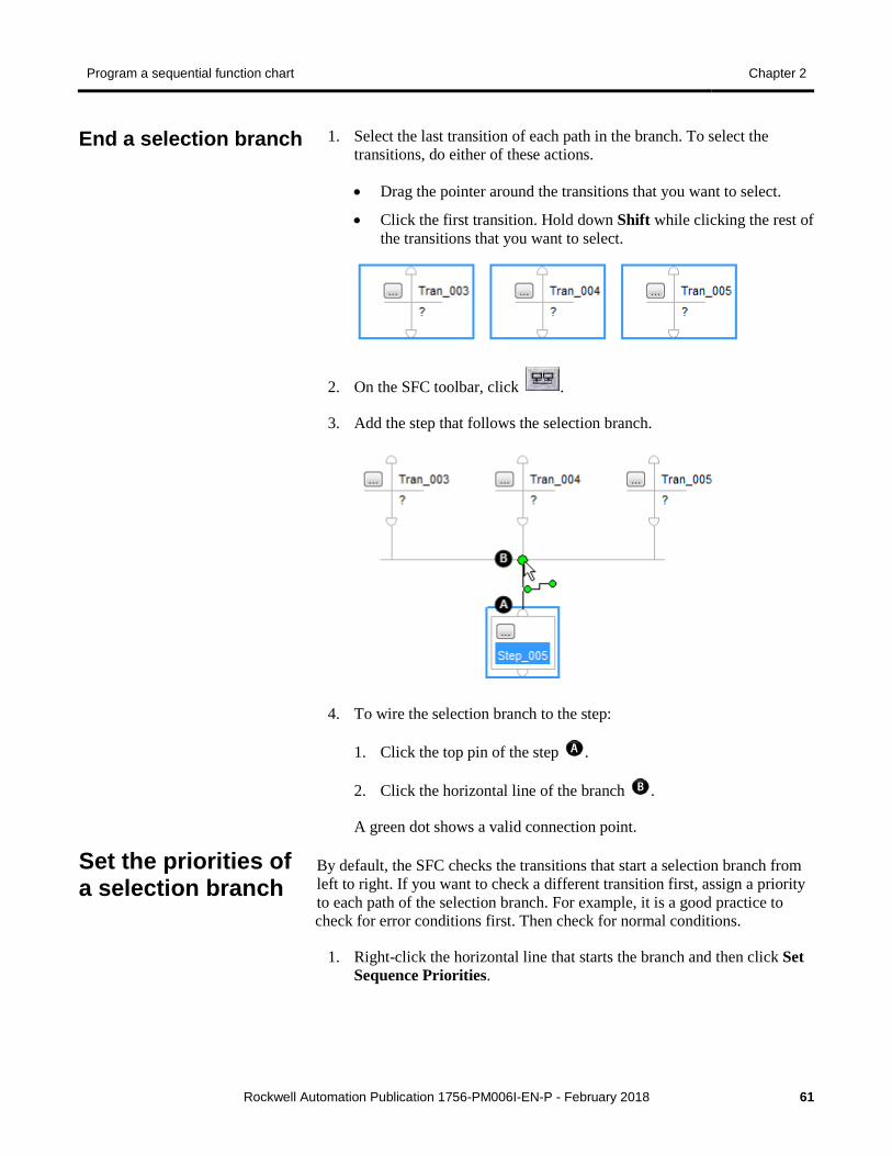
Program a sequential function chart Chapter 2
Rockwell Automation Publication 1756-PM006I-EN-P - February 2018 61
1. Select the last transition of each path in the branch. To select the transitions, do either of these actions.
• Drag the pointer around the transitions that you want to select.
• Click the first transition. Hold down Shift while clicking the rest of the transitions that you want to select.
2. On the SFC toolbar, click .
3. Add the step that follows the selection branch.
4. To wire the selection branch to the step:
1. Click the top pin of the step .
2. Click the horizontal line of the branch .
A green dot shows a valid connection point.
By default, the SFC checks the transitions that start a selection branch from left to right. If you want to check a different transition first, assign a priority to each path of the selection branch. For example, it is a good practice to check for error conditions first. Then check for normal conditions.
1. Right-click the horizontal line that starts the branch and then click Set Sequence Priorities.
End a selection branch
Set the priorities of a selection branch

Chapter 2 Program a sequential function chart
62 Rockwell Automation Publication 1756-PM006I-EN-P - February 2018
2. Clear the Use default priorities check box and select a transition.
Use the Move buttons to raise or lower the priority of the transition.
3. When all the transitions have the correct priority, click OK.
When you clear the Use default priorities check box, numbers show the priority of each transition.
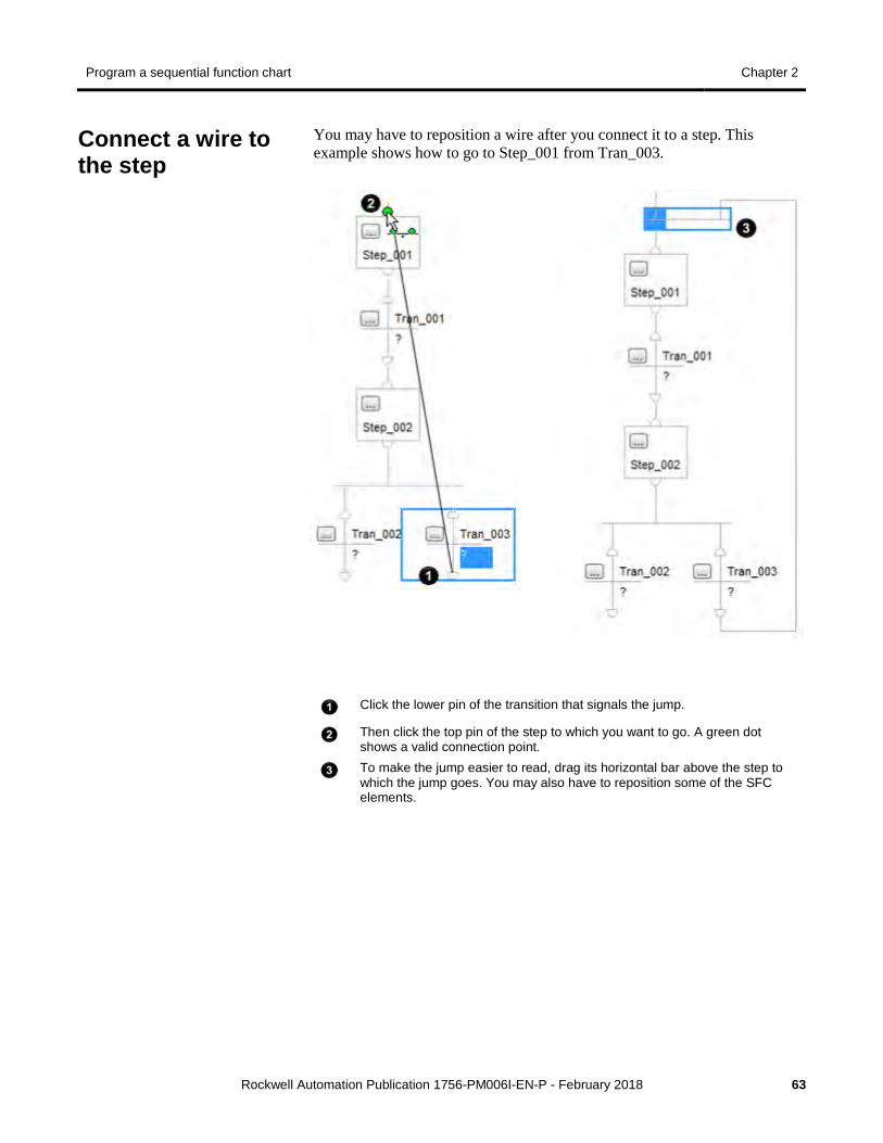
Program a sequential function chart Chapter 2
Rockwell Automation Publication 1756-PM006I-EN-P - February 2018 63
You may have to reposition a wire after you connect it to a step. This example shows how to go to Step_001 from Tran_003.
Click the lower pin of the transition that signals the jump.
Then click the top pin of the step to which you want to go. A green dot shows a valid connection point.
To make the jump easier to read, drag its horizontal bar above the step to which the jump goes. You may also have to reposition some of the SFC elements.
Connect a wire to the step
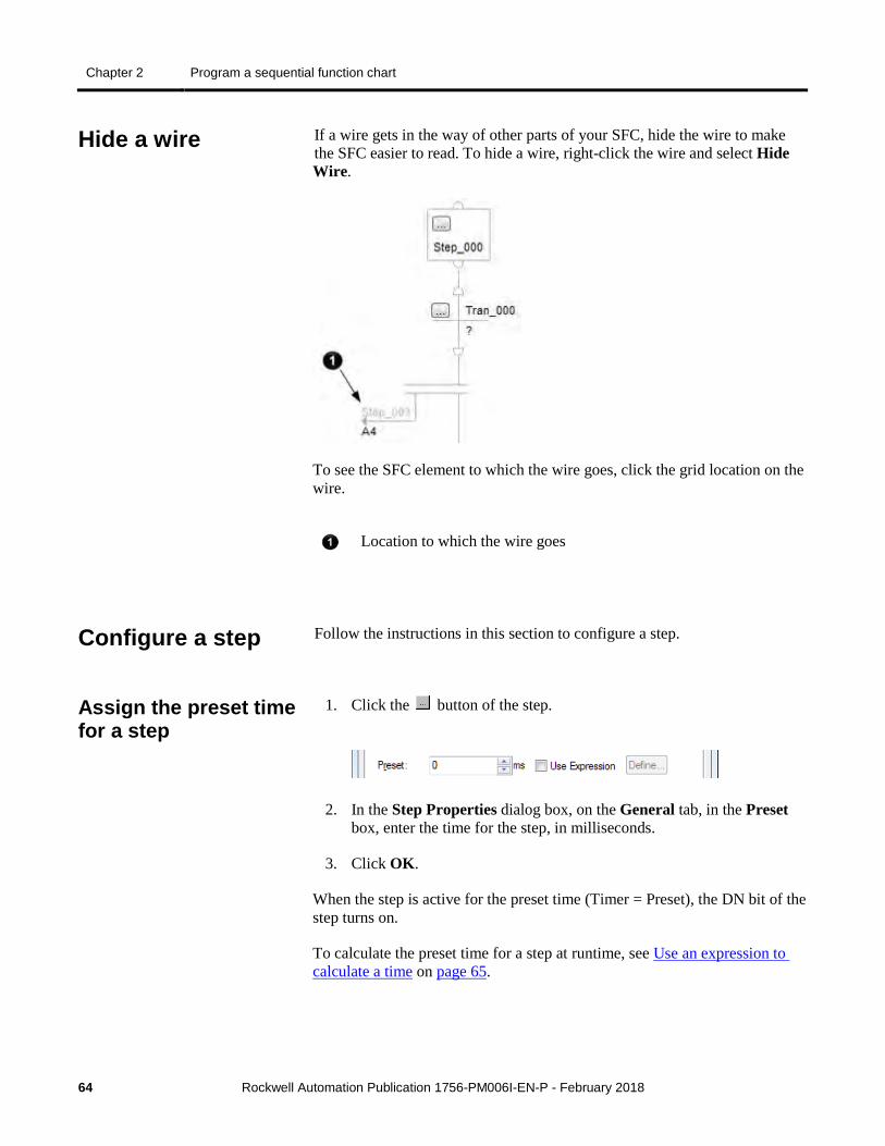
Chapter 2 Program a sequential function chart
64 Rockwell Automation Publication 1756-PM006I-EN-P - February 2018
If a wire gets in the way of other parts of your SFC, hide the wire to make the SFC easier to read. To hide a wire, right-click the wire and select Hide Wire.
To see the SFC element to which the wire goes, click the grid location on the wire.
Location to which the wire goes
Follow the instructions in this section to configure a step.
1. Click the button of the step.
2. In the Step Properties dialog box, on the General tab, in the Preset box, enter the time for the step, in milliseconds.
3. Click OK.
When the step is active for the preset time (Timer = Preset), the DN bit of the step turns on.
To calculate the preset time for a step at runtime, see Use an expression to calculate a time on page 65.
Hide a wire
Configure a step
Assign the preset time for a step
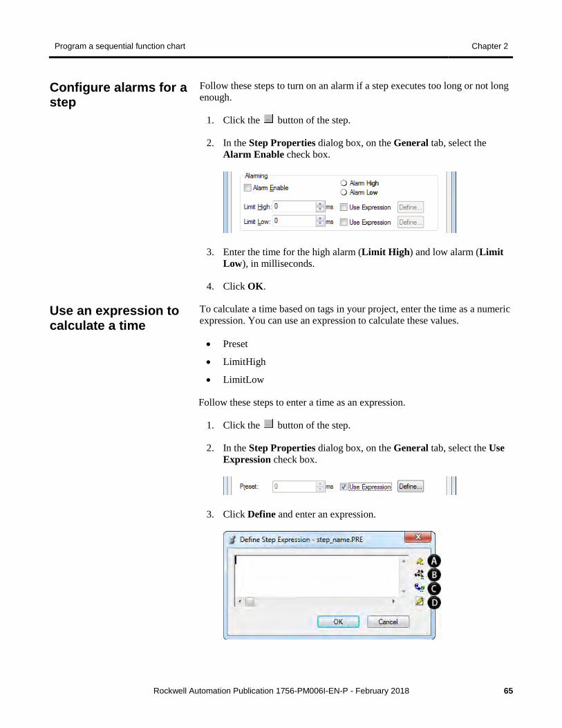
Program a sequential function chart Chapter 2
Rockwell Automation Publication 1756-PM006I-EN-P - February 2018 65
Follow these steps to turn on an alarm if a step executes too long or not long enough.
1. Click the button of the step.
2. In the Step Properties dialog box, on the General tab, select the Alarm Enable check box.
3. Enter the time for the high alarm (Limit High) and low alarm (Limit Low), in milliseconds.
4. Click OK.
To calculate a time based on tags in your project, enter the time as a numeric expression. You can use an expression to calculate these values.
• Preset
• LimitHigh
• LimitLow
Follow these steps to enter a time as an expression.
1. Click the button of the step.
2. In the Step Properties dialog box, on the General tab, select the Use Expression check box.
3. Click Define and enter an expression.
Configure alarms for a step
Use an expression to calculate a time
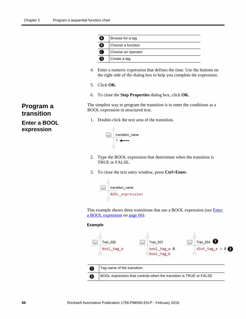
Chapter 2 Program a sequential function chart
66 Rockwell Automation Publication 1756-PM006I-EN-P - February 2018
Browse for a tag
Choose a function
Choose an operator
Create a tag
4. Enter a numeric expression that defines the time. Use the buttons on the right side of the dialog box to help you complete the expression.
5. Click OK.
6. To close the Step Properties dialog box, click OK.
The simplest way to program the transition is to enter the conditions as a BOOL expression in structured text.
1. Double-click the text area of the transition.
2. Type the BOOL expression that determines when the transition is TRUE or FALSE.
3. To close the text entry window, press Ctrl+Enter.
This example shows three transitions that use a BOOL expression (see Enter a BOOL expression on page 66).
Example
Tag name of the transition.
BOOL expression that controls when the transition is TRUE or FALSE
Program a transition Enter a BOOL expression
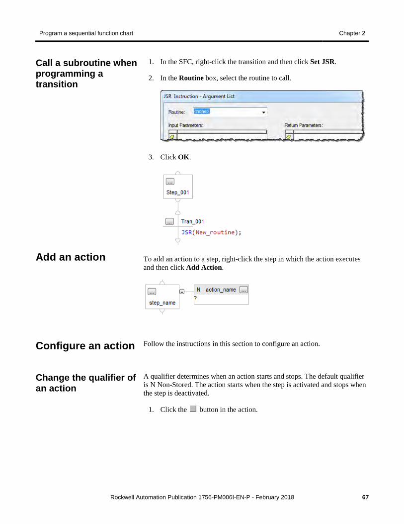
Program a sequential function chart Chapter 2
Rockwell Automation Publication 1756-PM006I-EN-P - February 2018 67
1. In the SFC, right-click the transition and then click Set JSR.
2. In the Routine box, select the routine to call.
3. Click OK.
To add an action to a step, right-click the step in which the action executes and then click Add Action.
Follow the instructions in this section to configure an action.
A qualifier determines when an action starts and stops. The default qualifier is N Non-Stored. The action starts when the step is activated and stops when the step is deactivated.
1. Click the button in the action.
Call a subroutine when programming a transition
Add an action
Configure an action
Change the qualifier of an action
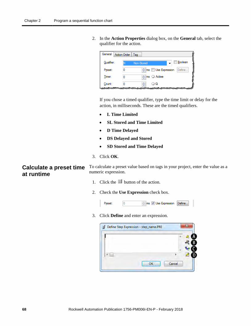
Chapter 2 Program a sequential function chart
68 Rockwell Automation Publication 1756-PM006I-EN-P - February 2018
2. In the Action Properties dialog box, on the General tab, select the qualifier for the action.
If you chose a timed qualifier, type the time limit or delay for the action, in milliseconds. These are the timed qualifiers.
• L Time Limited
• SL Stored and Time Limited
• D Time Delayed
• DS Delayed and Stored
• SD Stored and Time Delayed
3. Click OK.
To calculate a preset value based on tags in your project, enter the value as a numeric expression.
1. Click the button of the action.
2. Check the Use Expression check box.
3. Click Define and enter an expression.
Calculate a preset time at runtime
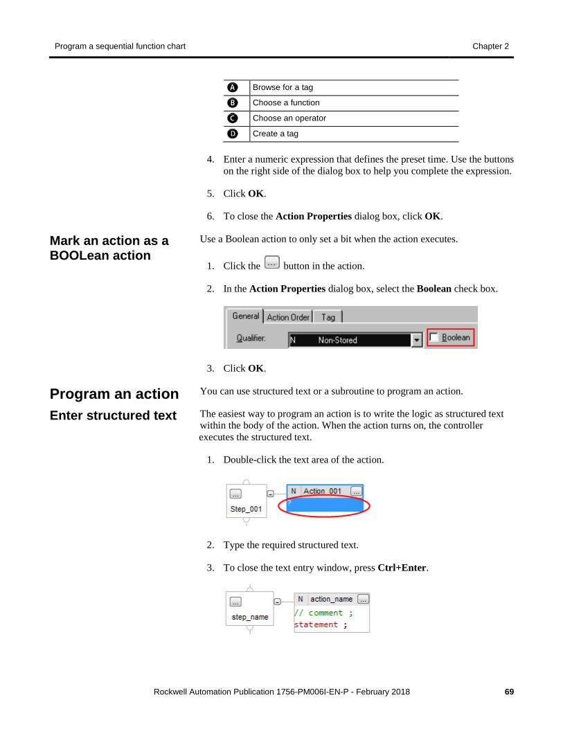
Program a sequential function chart Chapter 2
Rockwell Automation Publication 1756-PM006I-EN-P - February 2018 69
Browse for a tag
Choose a function
Choose an operator
Create a tag
4. Enter a numeric expression that defines the preset time. Use the buttons on the right side of the dialog box to help you complete the expression.
5. Click OK.
6. To close the Action Properties dialog box, click OK.
Use a Boolean action to only set a bit when the action executes.
1. Click the button in the action.
2. In the Action Properties dialog box, select the Boolean check box.
3. Click OK.
You can use structured text or a subroutine to program an action.
The easiest way to program an action is to write the logic as structured text within the body of the action. When the action turns on, the controller executes the structured text.
1. Double-click the text area of the action.
2. Type the required structured text.
3. To close the text entry window, press Ctrl+Enter.
Mark an action as a BOOLean action
Program an action Enter structured text
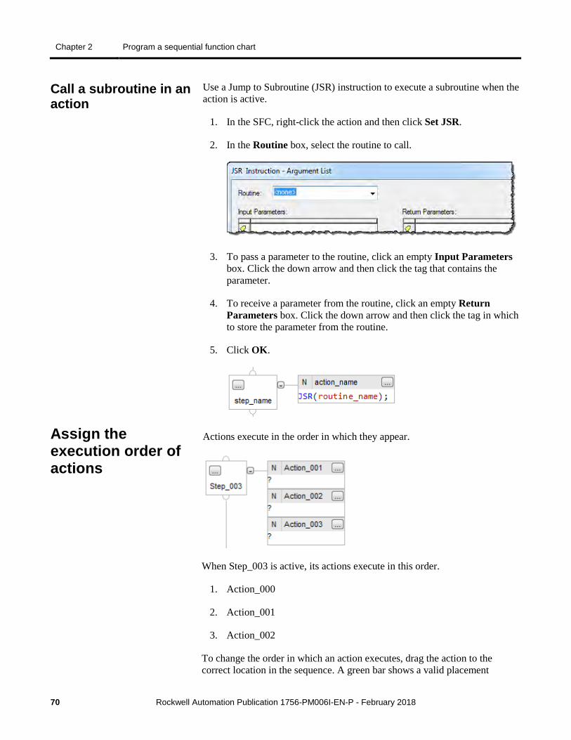
Chapter 2 Program a sequential function chart
70 Rockwell Automation Publication 1756-PM006I-EN-P - February 2018
Use a Jump to Subroutine (JSR) instruction to execute a subroutine when the action is active.
1. In the SFC, right-click the action and then click Set JSR.
2. In the Routine box, select the routine to call.
3. To pass a parameter to the routine, click an empty Input Parameters box. Click the down arrow and then click the tag that contains the parameter.
4. To receive a parameter from the routine, click an empty Return Parameters box. Click the down arrow and then click the tag in which to store the parameter from the routine.
5. Click OK.
Actions execute in the order in which they appear.
When Step_003 is active, its actions execute in this order.
1. Action_000
2. Action_001
3. Action_002
To change the order in which an action executes, drag the action to the correct location in the sequence. A green bar shows a valid placement
Call a subroutine in an action
Assign the execution order of actions
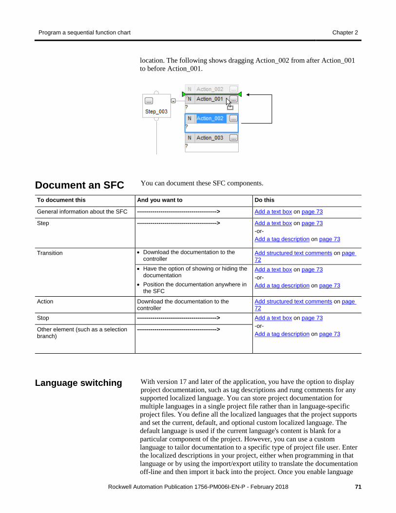
Program a sequential function chart Chapter 2
Rockwell Automation Publication 1756-PM006I-EN-P - February 2018 71
location. The following shows dragging Action_002 from after Action_001 to before Action_001.
You can document these SFC components.
To document this And you want to Do this
General information about the SFC -----------------------------------------> Add a text box on page 73
Step -----------------------------------------> Add a text box on page 73 -or- Add a tag description on page 73
Transition • Download the documentation to the controller
Add structured text comments on page 72
• Have the option of showing or hiding the documentation
• Position the documentation anywhere in the SFC
Add a text box on page 73 -or- Add a tag description on page 73
Action Download the documentation to the controller
Add structured text comments on page 72
Stop -----------------------------------------> Add a text box on page 73 -or- Add a tag description on page 73
Other element (such as a selection branch)
----------------------------------------->
With version 17 and later of the application, you have the option to display project documentation, such as tag descriptions and rung comments for any supported localized language. You can store project documentation for multiple languages in a single project file rather than in language-specific project files. You define all the localized languages that the project supports and set the current, default, and optional custom localized language. The default language is used if the current language's content is blank for a particular component of the project. However, you can use a custom language to tailor documentation to a specific type of project file user. Enter the localized descriptions in your project, either when programming in that language or by using the import/export utility to translate the documentation off-line and then import it back into the project. Once you enable language
Document an SFC
Language switching
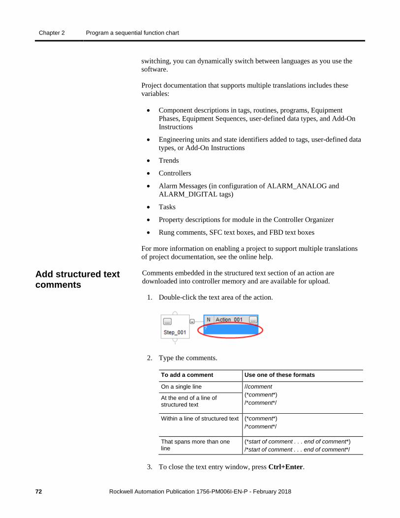
Chapter 2 Program a sequential function chart
72 Rockwell Automation Publication 1756-PM006I-EN-P - February 2018
switching, you can dynamically switch between languages as you use the software.
Project documentation that supports multiple translations includes these variables:
• Component descriptions in tags, routines, programs, Equipment Phases, Equipment Sequences, user-defined data types, and Add-On Instructions
• Engineering units and state identifiers added to tags, user-defined data types, or Add-On Instructions
• Trends
• Controllers
• Alarm Messages (in configuration of ALARM_ANALOG and ALARM_DIGITAL tags)
• Tasks
• Property descriptions for module in the Controller Organizer
• Rung comments, SFC text boxes, and FBD text boxes
For more information on enabling a project to support multiple translations of project documentation, see the online help.
Comments embedded in the structured text section of an action are downloaded into controller memory and are available for upload.
1. Double-click the text area of the action.
2. Type the comments.
To add a comment Use one of these formats
On a single line //comment (*comment*) /*comment*/
At the end of a line of structured text
Within a line of structured text (*comment*) /*comment*/
That spans more than one line
(*start of comment . . . end of comment*) /*start of comment . . . end of comment*/
3. To close the text entry window, press Ctrl+Enter.
Add structured text comments
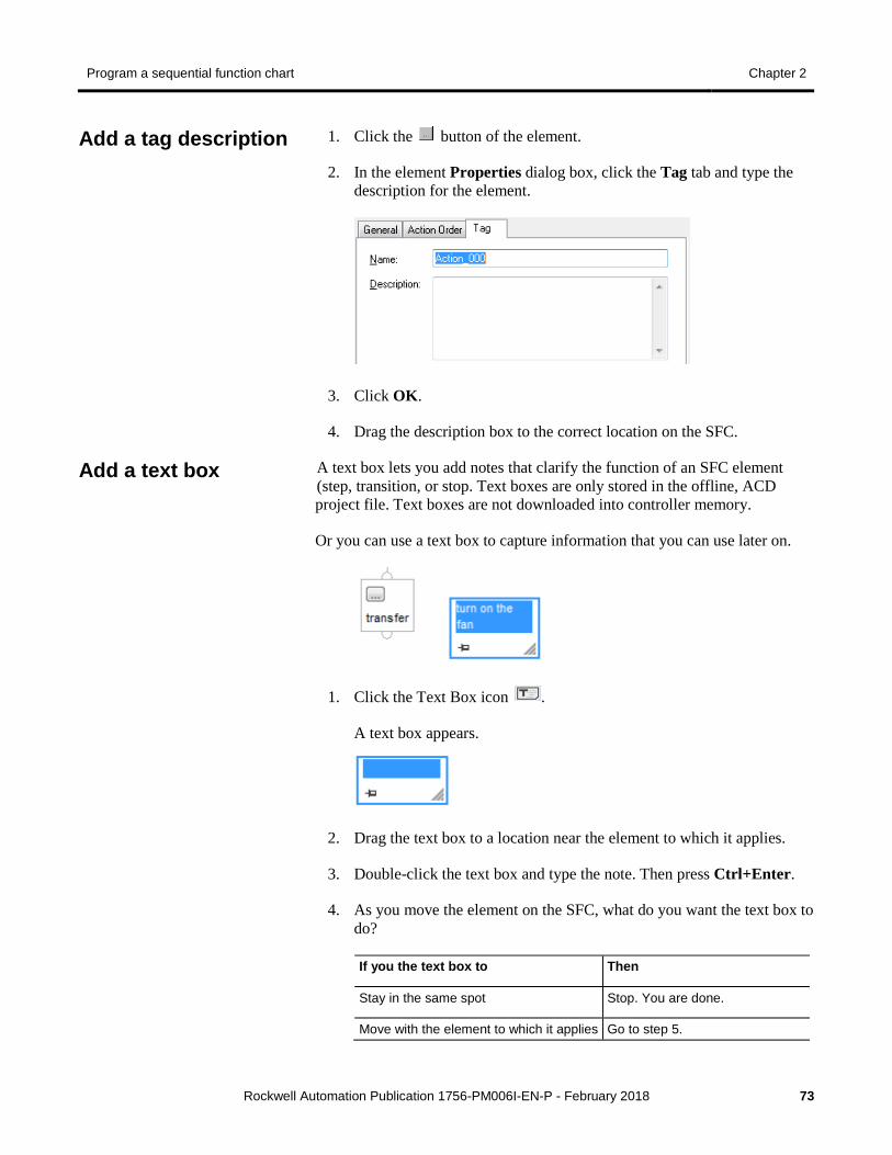
Program a sequential function chart Chapter 2
Rockwell Automation Publication 1756-PM006I-EN-P - February 2018 73
1. Click the button of the element.
2. In the element Properties dialog box, click the Tag tab and type the description for the element.
3. Click OK.
4. Drag the description box to the correct location on the SFC.
A text box lets you add notes that clarify the function of an SFC element (step, transition, or stop. Text boxes are only stored in the offline, ACD project file. Text boxes are not downloaded into controller memory.
Or you can use a text box to capture information that you can use later on.
1. Click the Text Box icon .
A text box appears.
2. Drag the text box to a location near the element to which it applies.
3. Double-click the text box and type the note. Then press Ctrl+Enter.
4. As you move the element on the SFC, what do you want the text box to do?
If you the text box to Then
Stay in the same spot Stop. You are done.
Move with the element to which it applies Go to step 5.
Add a tag description
Add a text box
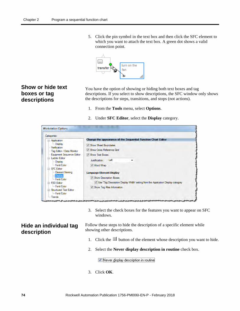
Chapter 2 Program a sequential function chart
74 Rockwell Automation Publication 1756-PM006I-EN-P - February 2018
5. Click the pin symbol in the text box and then click the SFC element to which you want to attach the text box. A green dot shows a valid connection point.
You have the option of showing or hiding both text boxes and tag descriptions. If you select to show descriptions, the SFC window only shows the descriptions for steps, transitions, and stops (not actions).
1. From the Tools menu, select Options.
2. Under SFC Editor, select the Display category.
3. Select the check boxes for the features you want to appear on SFC windows.
Follow these steps to hide the description of a specific element while showing other descriptions.
1. Click the button of the element whose description you want to hide.
2. Select the Never display description in routine check box.
3. Click OK.
Show or hide text boxes or tag descriptions
Hide an individual tag description
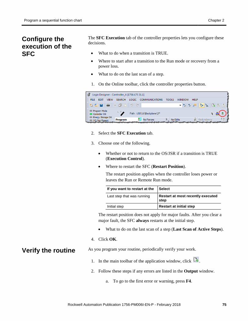
Program a sequential function chart Chapter 2
Rockwell Automation Publication 1756-PM006I-EN-P - February 2018 75
The SFC Execution tab of the controller properties lets you configure these decisions.
• What to do when a transition is TRUE.
• Where to start after a transition to the Run mode or recovery from a power loss.
• What to do on the last scan of a step.
1. On the Online toolbar, click the controller properties button.
2. Select the SFC Execution tab.
3. Choose one of the following.
• Whether or not to return to the OS/JSR if a transition is TRUE (Execution Control).
• Where to restart the SFC (Restart Position).
The restart position applies when the controller loses power or leaves the Run or Remote Run mode.
If you want to restart at the Select
Last step that was running Restart at most recently executed step
Initial step Restart at initial step
The restart position does not apply for major faults. After you clear a major fault, the SFC always restarts at the initial step.
• What to do on the last scan of a step (Last Scan of Active Steps).
4. Click OK.
As you program your routine, periodically verify your work.
1. In the main toolbar of the application window, click .
2. Follow these steps if any errors are listed in the Output window.
a. To go to the first error or warning, press F4.
Configure the execution of the SFC
Verify the routine
Chapter 2 Program a sequential function chart
76 Rockwell Automation Publication 1756-PM006I-EN-P - February 2018
b. Correct the error according to the description in the in the Output window on the Search Results tab.
c. Repeat step 1.
3. To close the Results window, press Alt+1.
To check your SFC, you can use either of these options.
• Force transitions
• Step through the SFC
See the chapter on Force steps on page 77.
Firmware revision 13 added support for editing SFCs online. When you transition the controller to test or un-test edits, the controller resets the SFC and starts execution at the initial step. Keep these guidelines in mind if you edit an SFC online.
• Time when you test or un-test edits to coincide with the SFC execution of the initial step.
• Place structured text logic in subroutines to minimize the impact of online edits.
• Use an SFR instruction to programmatically shift SFC execution to the correct step.
As of firmware revision 18, the following online edits to an SFC no longer reset the SFC to the initial step.
• Modify structured text in actions and transitions
• Physically move steps, actions, and transitions on SFC sheets without changing the wiring
• Add, delete, or modify text and description boxes
• Modify indicator tags
• Add, delete or modify an SBR/RET
• Add, delete or modify any step or action expression
Edit an SFC online
Maintain active SFC step
Rockwell Automation Publication 1756-PM006I-EN-P - February 2018 77
Chapter 3
Force steps
Use a force to override data that your logic either uses or produces.
• Test and debug your logic.
• Temporarily keep your process functioning when an input device has failed.
Use forces only as a temporary measure. They are not intended to be a permanent part of your application.
Make sure you understand the following before using forces.
ATTENTION
Forcing can cause unexpected machine motion that could injure personnel. Before you use a force, determine how the force will affect your machine or process and keep personnel away from the machine area. • Enabling SFC forces causes your machine or process to go to a
different state or phase. • Removing forces may still leave forces in the enabled state. • If forces are enabled and you install a force, the new force
immediately takes effect.
For a force to take effect, you enable forces. You can only enable and disable forces at the controller level.
• You can enable I/O forces and SFC forces separately or at the same time.
• You cannot enable or disable forces for a specific module, tag collection, or tag element.
Introduction
Precautions
Enable forces
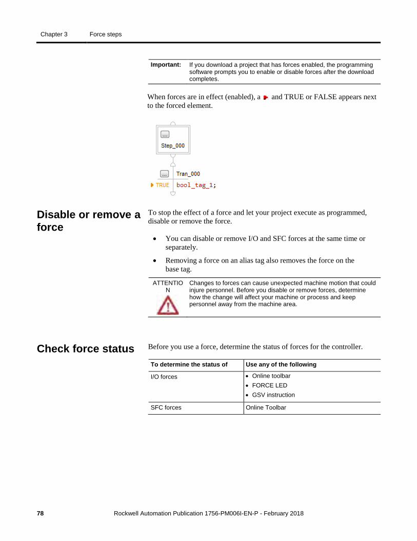
Chapter 3 Force steps
78 Rockwell Automation Publication 1756-PM006I-EN-P - February 2018
Important: If you download a project that has forces enabled, the programming software prompts you to enable or disable forces after the download completes.
When forces are in effect (enabled), a and TRUE or FALSE appears next to the forced element.
To stop the effect of a force and let your project execute as programmed, disable or remove the force.
• You can disable or remove I/O and SFC forces at the same time or separately.
• Removing a force on an alias tag also removes the force on the base tag.
ATTENTION
Changes to forces can cause unexpected machine motion that could injure personnel. Before you disable or remove forces, determine how the change will affect your machine or process and keep personnel away from the machine area.
Before you use a force, determine the status of forces for the controller.
To determine the status of Use any of the following
I/O forces • Online toolbar • FORCE LED • GSV instruction
SFC forces Online Toolbar
Disable or remove a force
Check force status
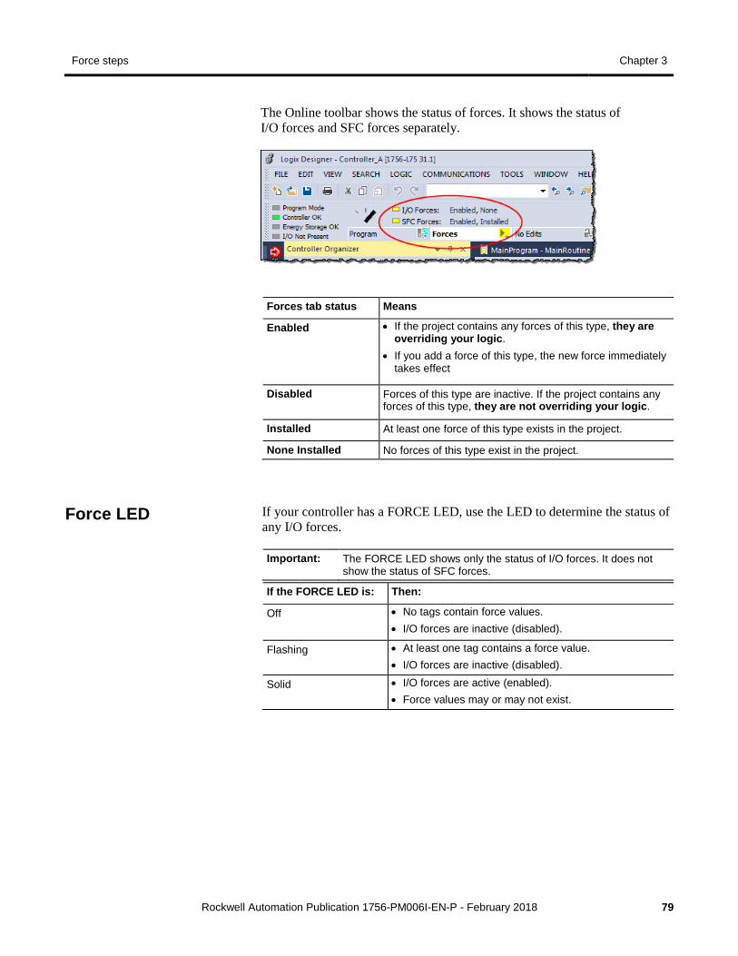
Force steps Chapter 3
Rockwell Automation Publication 1756-PM006I-EN-P - February 2018 79
The Online toolbar shows the status of forces. It shows the status of I/O forces and SFC forces separately.
Forces tab status Means
Enabled • If the project contains any forces of this type, they are overriding your logic.
• If you add a force of this type, the new force immediately takes effect
Disabled Forces of this type are inactive. If the project contains any forces of this type, they are not overriding your logic.
Installed At least one force of this type exists in the project.
None Installed No forces of this type exist in the project.
If your controller has a FORCE LED, use the LED to determine the status of any I/O forces.
Important: The FORCE LED shows only the status of I/O forces. It does not show the status of SFC forces.
If the FORCE LED is: Then:
Off • No tags contain force values. • I/O forces are inactive (disabled).
Flashing • At least one tag contains a force value. • I/O forces are inactive (disabled).
Solid • I/O forces are active (enabled). • Force values may or may not exist.
Force LED
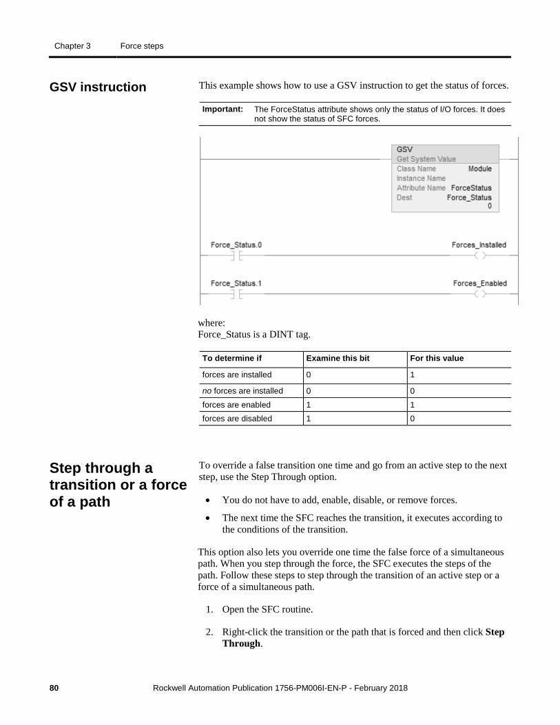
Chapter 3 Force steps
80 Rockwell Automation Publication 1756-PM006I-EN-P - February 2018
This example shows how to use a GSV instruction to get the status of forces.
Important: The ForceStatus attribute shows only the status of I/O forces. It does not show the status of SFC forces.
where: Force_Status is a DINT tag.
To determine if Examine this bit For this value
forces are installed 0 1
no forces are installed 0 0
forces are enabled 1 1
forces are disabled 1 0
To override a false transition one time and go from an active step to the next step, use the Step Through option.
• You do not have to add, enable, disable, or remove forces.
• The next time the SFC reaches the transition, it executes according to the conditions of the transition.
This option also lets you override one time the false force of a simultaneous path. When you step through the force, the SFC executes the steps of the path. Follow these steps to step through the transition of an active step or a force of a simultaneous path.
1. Open the SFC routine.
2. Right-click the transition or the path that is forced and then click Step Through.
GSV instruction
Step through a transition or a force of a path
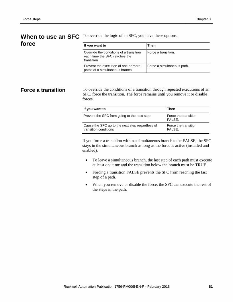
Force steps Chapter 3
Rockwell Automation Publication 1756-PM006I-EN-P - February 2018 81
To override the logic of an SFC, you have these options.
If you want to Then
Override the conditions of a transition each time the SFC reaches the transition
Force a transition.
Prevent the execution of one or more paths of a simultaneous branch
Force a simultaneous path.
To override the conditions of a transition through repeated executions of an SFC, force the transition. The force remains until you remove it or disable forces.
If you want to Then
Prevent the SFC from going to the next step Force the transition FALSE.
Cause the SFC go to the next step regardless of transition conditions
Force the transition FALSE.
If you force a transition within a simultaneous branch to be FALSE, the SFC stays in the simultaneous branch as long as the force is active (installed and enabled).
• To leave a simultaneous branch, the last step of each path must execute at least one time and the transition below the branch must be TRUE.
• Forcing a transition FALSE prevents the SFC from reaching the last step of a path.
• When you remove or disable the force, the SFC can execute the rest of the steps in the path.
When to use an SFC force
Force a transition
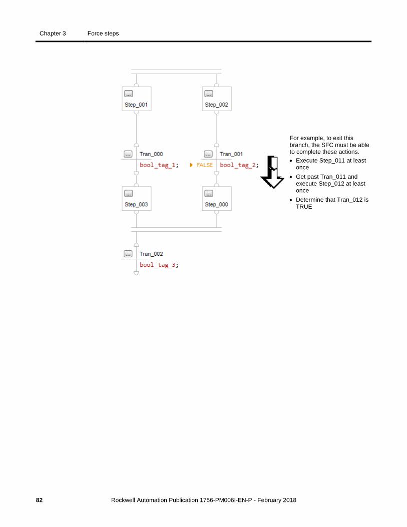
Chapter 3 Force steps
82 Rockwell Automation Publication 1756-PM006I-EN-P - February 2018
For example, to exit this branch, the SFC must be able to complete these actions. • Execute Step_011 at least
once • Get past Tran_011 and
execute Step_012 at least once
• Determine that Tran_012 is TRUE
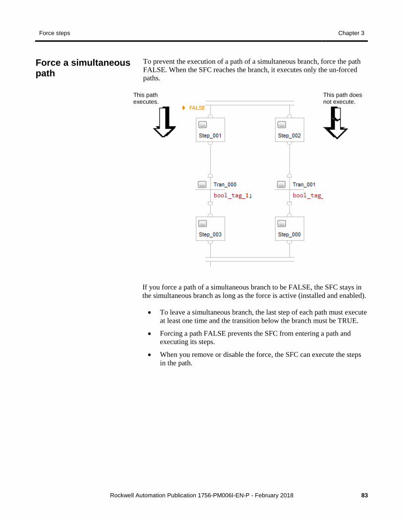
Force steps Chapter 3
Rockwell Automation Publication 1756-PM006I-EN-P - February 2018 83
To prevent the execution of a path of a simultaneous branch, force the path FALSE. When the SFC reaches the branch, it executes only the un-forced paths.
This path executes.
This path does not execute.
If you force a path of a simultaneous branch to be FALSE, the SFC stays in the simultaneous branch as long as the force is active (installed and enabled).
• To leave a simultaneous branch, the last step of each path must execute at least one time and the transition below the branch must be TRUE.
• Forcing a path FALSE prevents the SFC from entering a path and executing its steps.
• When you remove or disable the force, the SFC can execute the steps in the path.
Force a simultaneous path
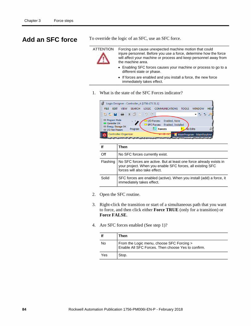
Chapter 3 Force steps
84 Rockwell Automation Publication 1756-PM006I-EN-P - February 2018
To override the logic of an SFC, use an SFC force.
ATTENTION
Forcing can cause unexpected machine motion that could injure personnel. Before you use a force, determine how the force will affect your machine or process and keep personnel away from the machine area. • Enabling SFC forces causes your machine or process to go to a
different state or phase. • If forces are enabled and you install a force, the new force
immediately takes effect.
1. What is the state of the SFC Forces indicator?
If Then
Off No SFC forces currently exist.
Flashing No SFC forces are active. But at least one force already exists in your project. When you enable SFC forces, all existing SFC forces will also take effect.
Solid SFC forces are enabled (active). When you install (add) a force, it immediately takes effect.
2. Open the SFC routine.
3. Right-click the transition or start of a simultaneous path that you want to force, and then click either Force TRUE (only for a transition) or Force FALSE.
4. Are SFC forces enabled (See step 1)?
If Then
No From the Logic menu, choose SFC Forcing > Enable All SFC Forces. Then choose Yes to confirm.
Yes Stop.
Add an SFC force
Force steps Chapter 3
Rockwell Automation Publication 1756-PM006I-EN-P - February 2018 85
Make sure you understand the following before using forces.
ATTENTIO
N
Changes to forces can cause unexpected machine motion that could injure personnel. Before you disable or remove forces, determine how the change will affect your machine or process and keep personnel away from the machine area.
From the Logic menu, click SFC Forcing and then click Disable All SFC Forces. Then click Yes to confirm.
From the Logic menu, click SFC Forcing and then click Remove All SFC Forces. Then click Yes to confirm.
Remove or disable forces
Disable all SFC forces
Remove all SFC forces


Rockwell Automation Publication 1756-PM006I-EN-P - February 2018 87
A action 69
assign qualifier 67 boolean 29 call a subroutine 69 choose between boolean and non-boolean 28 data type 30 non-boolean 28 program 28 reset 46 store 46 use expression 68 use of boolean action 29 use of structured text 69
alarm sequential function chart 35, 64
automatic reset sequential function chart 43
B BOOL expression
sequential function chart 34, 66 boolean action 29, 69
program 29 branch
sequential function chart 23
C call a subroutine 35, 67, 69 configure
alarm 64 step 64
D disable
force 78 documentation
show or hide in sequential function chart 74 don't scan
sequential function chart 40
E enable
force 77 EOT instruction 69 expression
BOOL expression 34, 66 numeric expression 65, 68
F force
disable 78 enable 77 LED 78 monitor 78 remove 78
function block diagram force a value 77
J jump
sequential function chart 27
L ladder logic
force a value 77 override a value 77
last scan sequential function chart 38
LED force 78
M mark as boolean 69 monitor
forces 78
N numeric expression 65, 68
Index
Index
88 Rockwell Automation Publication 1756-PM006I-EN-P - February 2018
P periodic task
application for 17 postscan
sequential function chart 38 program
action 28 boolean action 29
programmatic reset option 41
Q qualifier
assign 67
R remove
force 78 reset
action 46 SFC 49
reset an SFC 50 restart
sequential function chart 49 routine
as transition 69 nest within sequential function chart 50 verify 75
S selection branch
overview 25 sequential function chart
action 28, 46, 69 automatic reset option 43 boolean action 29 call a subroutine 69 define tasks 17 don't scan option 40 force element 77 last scan 38 nest 50 numeric expression 65, 68 organize steps 23 programmatic reset option 41 reset 38, 49, 50
restart 49 selection branch 25 sequence 25 show or hide documentation 74 simultaneous branch 26 step 23, 64 stop 48 text box 73 wire 27
SFC_ACTION structure 30 SFC_STEP structure 20 SFC_STOP structure 50 SFR instruction 49, 50 simultaneous branch 26 status
force 78 step
alarm 35 assign preset time 64 configure 64 configure alarm 64 data type 20 organize in sequential function chart 23 selection branch 25 sequence 25 simultaneous branch 26 timer 35
stop data type 50 sequential function chart 48
store action 46
structure SFC_ACTION 30 SFC_STEP 20 SFC_STOP 50
structured text comments 72 force a value 77 in action 69
subroutine call a subroutine 35, 67, 69
T task
define 17 text box
Index
Rockwell Automation Publication 1756-PM006I-EN-P - February 2018 89
sequential function chart 73 show or hide in sequential function chart 74
transition BOOL expression 34 call a subroutine 35, 67 choose program method 34 EOT instruction 69 use of a subroutine 69
V verify
routine 75
W wire
sequential function chart 27
Rockwell Automation Publication 1756-PM006I-EN-P - February 2018
Supersedes Publication 1756-PM006H-EN-P - December 2016 Copyright © 2018 Rockwell Automation Technologies, Inc. All Rights Reserved. Printed in the U.S.A.
Rockwell Automation support Rockwell Automation provides technical information on the web to assist you in using its products. At http://www.rockwellautomation.com/support you can find technical and application notes, sample code, and links to software service packs. You can also visit our Support Center at https://rockwellautomation.custhelp.com for software updates, support chats and forums, technical information, FAQs, and to sign up for product notification updates.
In addition, we offer multiple support programs for installation, configuration, and troubleshooting. For more information, contact your local distributor or Rockwell Automation representative, or visit http://www.rockwellautomation.com/services/online-phone.
Installation assistance If you experience a problem within the first 24 hours of installation, review the information that is contained in this manual. You can contact Customer Support for initial help in getting your product up and running.
United States or Canada 1.440.646.3434 Outside United States or Canada Use the Worldwide Locator available at http://www.rockwellautomation.com/locations,
or contact your local Rockwell Automation representative.
New product satisfaction return Rockwell Automation tests all of its products to ensure that they are fully operational when shipped from the manufacturing facility. However, if your product is not functioning and needs to be returned, follow these procedures.
United States Contact your distributor. You must provide a Customer Support case number (call the phone number above to obtain one) to your distributor to complete the return process.
Outside United States Please contact your local Rockwell Automation representative for the return procedure.
Documentation feedback Your comments will help us serve your documentation needs better. If you have any suggestions on how to improve this document, complete the feedback form, publication RA-DU002.