logix5000 controllers i/o and tag data programming … 5000 environment is the logix designer...
TRANSCRIPT

Programming Manual
Logix5000 Controllers I/O and Tag DataCatalog Numbers 1756 ControlLogix, 1756 GuardLogix, 1768 Compact GuardLogix, 1769 CompactLogix, 1789 SoftLogix, PowerFlex with DriveLogix
Important User InformationSolid-state equipment has operational characteristics differing from those of electromechanical equipment. Safety Guidelines for the Application, Installation and Maintenance of Solid State Controls (publication SGI-1.1 available from your local Rockwell Automation sales office or online at http://www.rockwellautomation.com/literature/) describes some important differences between solid-state equipment and hard-wired electromechanical devices. Because of this difference, and also because of the wide variety of uses for solid-state equipment, all persons responsible for applying this equipment must satisfy themselves that each intended application of this equipment is acceptable.
In no event will Rockwell Automation, Inc. be responsible or liable for indirect or consequential damages resulting from the use or application of this equipment.
The examples and diagrams in this manual are included solely for illustrative purposes. Because of the many variables and requirements associated with any particular installation, Rockwell Automation, Inc. cannot assume responsibility or liability for actual use based on the examples and diagrams.
No patent liability is assumed by Rockwell Automation, Inc. with respect to use of information, circuits, equipment, or software described in this manual.
Reproduction of the contents of this manual, in whole or in part, without written permission of Rockwell Automation, Inc., is prohibited.
Throughout this manual, when necessary, we use notes to make you aware of safety considerations.
Allen-Bradley, Rockwell Software, Rockwell Automation, and TechConnect are trademarks of Rockwell Automation, Inc.
Trademarks not belonging to Rockwell Automation are property of their respective companies.2012
WARNING: Identifies information about practices or circumstances that can cause an explosion in a hazardous environment, which may lead to personal injury or death, property damage, or economic loss.
ATTENTION: Identifies information about practices or circumstances that can lead to personal injury or death, property damage, or economic loss. Attentions help you identify a hazard, avoid a hazard, and recognize the consequence
SHOCK HAZARD: Labels may be on or inside the equipment, for example, a drive or motor, to alert people that dangerous voltage may be present.
BURN HAZARD: Labels may be on or inside the equipment, for example, a drive or motor, to alert people that surfaces may reach dangerous temperatures.
IMPORTANT Identifies information that is critical for successful application and understanding of the product.
Summary of Changes
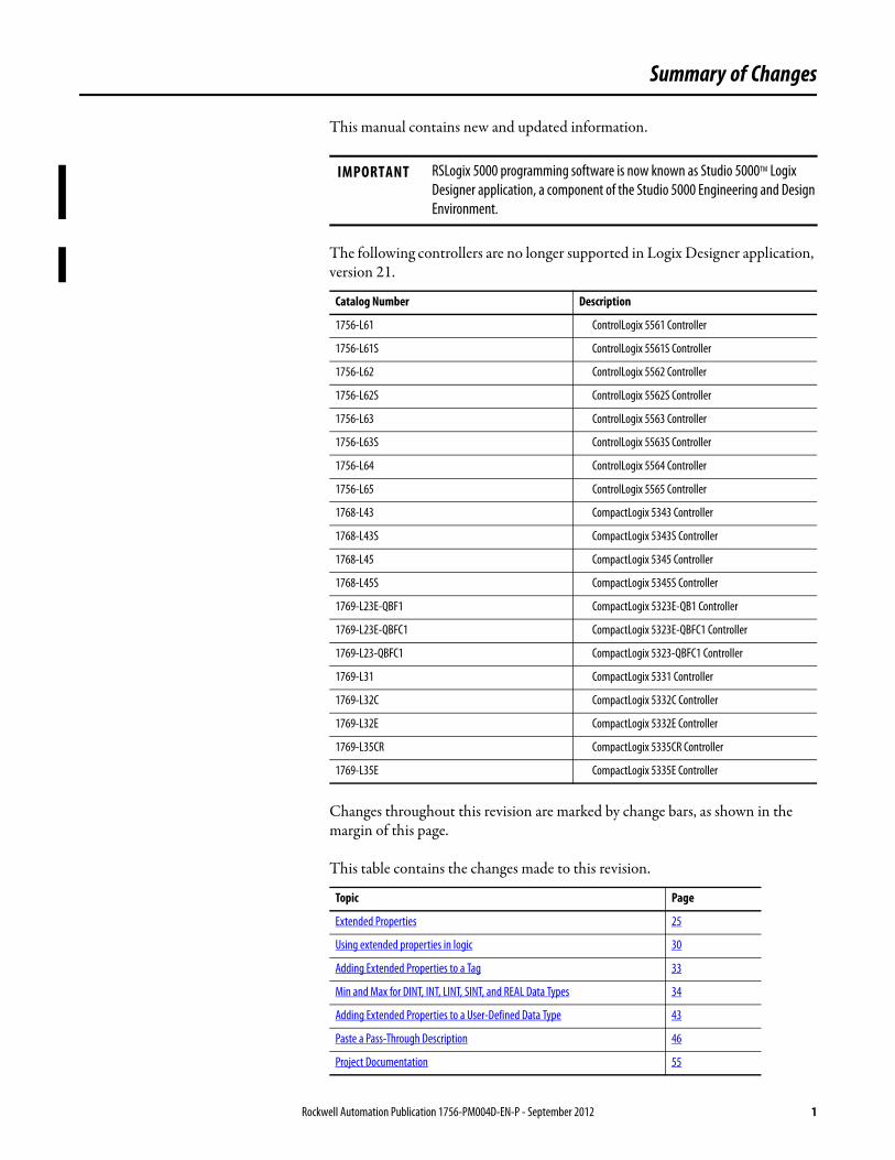
This manual contains new and updated information.
The following controllers are no longer supported in Logix Designer application, version 21.
Changes throughout this revision are marked by change bars, as shown in the margin of this page.
This table contains the changes made to this revision.
IMPORTANT RSLogix 5000 programming software is now known as Studio 5000TM Logix Designer application, a component of the Studio 5000 Engineering and Design Environment.
Catalog Number Description
1756-L61 ControlLogix 5561 Controller
1756-L61S ControlLogix 5561S Controller
1756-L62 ControlLogix 5562 Controller
1756-L62S ControlLogix 5562S Controller
1756-L63 ControlLogix 5563 Controller
1756-L63S ControlLogix 5563S Controller
1756-L64 ControlLogix 5564 Controller
1756-L65 ControlLogix 5565 Controller
1768-L43 CompactLogix 5343 Controller
1768-L43S CompactLogix 5343S Controller
1768-L45 CompactLogix 5345 Controller
1768-L45S CompactLogix 5345S Controller
1769-L23E-QBF1 CompactLogix 5323E-QB1 Controller
1769-L23E-QBFC1 CompactLogix 5323E-QBFC1 Controller
1769-L23-QBFC1 CompactLogix 5323-QBFC1 Controller
1769-L31 CompactLogix 5331 Controller
1769-L32C CompactLogix 5332C Controller
1769-L32E CompactLogix 5332E Controller
1769-L35CR CompactLogix 5335CR Controller
1769-L35E CompactLogix 5335E Controller
Topic Page
Extended Properties 25
Using extended properties in logic 30
Adding Extended Properties to a Tag 33
Min and Max for DINT, INT, LINT, SINT, and REAL Data Types 34
Adding Extended Properties to a User-Defined Data Type 43
Paste a Pass-Through Description 46
Project Documentation 55
Rockwell Automation Publication 1756-PM004D-EN-P - September 2012 1

Summary of Changes
Notes:
2 Rockwell Automation Publication 1756-PM004D-EN-P - September 2012
Table of Contents
Preface Studio 5000 Engineering and Design Environment and Logix Designer Application . . . . . . . . . . . . . . . . . . . . . . . . . . . . . . . . . . . . . . . . . 5Purpose of This Manual . . . . . . . . . . . . . . . . . . . . . . . . . . . . . . . . . . . . . . . . . . . . 5
Chapter 1Communicate with I/O Modules Introduction. . . . . . . . . . . . . . . . . . . . . . . . . . . . . . . . . . . . . . . . . . . . . . . . . . . . . . . 7
Requested Packet Interval. . . . . . . . . . . . . . . . . . . . . . . . . . . . . . . . . . . . . . . . . . . 8Communication Format . . . . . . . . . . . . . . . . . . . . . . . . . . . . . . . . . . . . . . . . . . . . 8
Direct or Rack-Optimized Connection. . . . . . . . . . . . . . . . . . . . . . . . . . . 9Ownership. . . . . . . . . . . . . . . . . . . . . . . . . . . . . . . . . . . . . . . . . . . . . . . . . . . . . 9
Electronic Keying . . . . . . . . . . . . . . . . . . . . . . . . . . . . . . . . . . . . . . . . . . . . . . . . 12Exact Match . . . . . . . . . . . . . . . . . . . . . . . . . . . . . . . . . . . . . . . . . . . . . . . . . 13Compatible Module . . . . . . . . . . . . . . . . . . . . . . . . . . . . . . . . . . . . . . . . . . 14
Address I/O Data . . . . . . . . . . . . . . . . . . . . . . . . . . . . . . . . . . . . . . . . . . . . . . . . 19Buffer I/O . . . . . . . . . . . . . . . . . . . . . . . . . . . . . . . . . . . . . . . . . . . . . . . . . . . . . . . 20
Chapter 2Organizing Tags Introduction. . . . . . . . . . . . . . . . . . . . . . . . . . . . . . . . . . . . . . . . . . . . . . . . . . . . . 23
Tag Type . . . . . . . . . . . . . . . . . . . . . . . . . . . . . . . . . . . . . . . . . . . . . . . . . . . . 24Data Type . . . . . . . . . . . . . . . . . . . . . . . . . . . . . . . . . . . . . . . . . . . . . . . . . . . 25Scope . . . . . . . . . . . . . . . . . . . . . . . . . . . . . . . . . . . . . . . . . . . . . . . . . . . . . . . . 27
Guidelines for Tags. . . . . . . . . . . . . . . . . . . . . . . . . . . . . . . . . . . . . . . . . . . . . . . 29Create a Tag . . . . . . . . . . . . . . . . . . . . . . . . . . . . . . . . . . . . . . . . . . . . . . . . . . . . . 33
Adding Extended Properties to a Tag. . . . . . . . . . . . . . . . . . . . . . . . . . . 33Create an Array . . . . . . . . . . . . . . . . . . . . . . . . . . . . . . . . . . . . . . . . . . . . . . . . . . 35
Configuring an Array . . . . . . . . . . . . . . . . . . . . . . . . . . . . . . . . . . . . . . . . . 38Creating a User-defined Data Type . . . . . . . . . . . . . . . . . . . . . . . . . . . . . . . . 39
Guidelines for User-defined Data Types . . . . . . . . . . . . . . . . . . . . . . . . 40Creating a User-defined Data Type . . . . . . . . . . . . . . . . . . . . . . . . . . . . 41Adding Extended Properties to a User-Defined Data Type . . . . . . . 43
Describing a User-defined Data Type . . . . . . . . . . . . . . . . . . . . . . . . . . . . . . 44Activate Pass-Through and Append Descriptions . . . . . . . . . . . . . . . 45Paste a Pass-Through Description. . . . . . . . . . . . . . . . . . . . . . . . . . . . . . 46
Address Tag Data . . . . . . . . . . . . . . . . . . . . . . . . . . . . . . . . . . . . . . . . . . . . . . . . 47Alias Tags . . . . . . . . . . . . . . . . . . . . . . . . . . . . . . . . . . . . . . . . . . . . . . . . . . . . . . . 48
Display Alias Information . . . . . . . . . . . . . . . . . . . . . . . . . . . . . . . . . . . . . 49Assign an Alias . . . . . . . . . . . . . . . . . . . . . . . . . . . . . . . . . . . . . . . . . . . . . . . 50
Assign an Indirect Address . . . . . . . . . . . . . . . . . . . . . . . . . . . . . . . . . . . . . . . . 51Expressions . . . . . . . . . . . . . . . . . . . . . . . . . . . . . . . . . . . . . . . . . . . . . . . . . . 52Array Subscript Out of Range . . . . . . . . . . . . . . . . . . . . . . . . . . . . . . . . . 54
Tag Documentation. . . . . . . . . . . . . . . . . . . . . . . . . . . . . . . . . . . . . . . . . . . . . . 55Project Documentation . . . . . . . . . . . . . . . . . . . . . . . . . . . . . . . . . . . . . . . 55
Rockwell Automation Publication 1756-PM004D-EN-P - September 2012 3
Table of Contents
Chapter 3Force I/O Introduction . . . . . . . . . . . . . . . . . . . . . . . . . . . . . . . . . . . . . . . . . . . . . . . . . . . . . 57
Precautions . . . . . . . . . . . . . . . . . . . . . . . . . . . . . . . . . . . . . . . . . . . . . . . . . . . . . . 57Enable Forces. . . . . . . . . . . . . . . . . . . . . . . . . . . . . . . . . . . . . . . . . . . . . . . . . 57Disable or Remove a Force. . . . . . . . . . . . . . . . . . . . . . . . . . . . . . . . . . . . . 58
Check Force Status . . . . . . . . . . . . . . . . . . . . . . . . . . . . . . . . . . . . . . . . . . . . . . . 58FORCE Status Indicator . . . . . . . . . . . . . . . . . . . . . . . . . . . . . . . . . . . . . . 59GSV Instruction . . . . . . . . . . . . . . . . . . . . . . . . . . . . . . . . . . . . . . . . . . . . . . 59
When to Use I/O Force. . . . . . . . . . . . . . . . . . . . . . . . . . . . . . . . . . . . . . . . . . . 60Force an Input Value . . . . . . . . . . . . . . . . . . . . . . . . . . . . . . . . . . . . . . . . . . 61Force an Output Value . . . . . . . . . . . . . . . . . . . . . . . . . . . . . . . . . . . . . . . . 61
Add an I/O Force . . . . . . . . . . . . . . . . . . . . . . . . . . . . . . . . . . . . . . . . . . . . . . . . 61Remove or Disable Forces . . . . . . . . . . . . . . . . . . . . . . . . . . . . . . . . . . . . . . . . . 62
Remove an Individual Force . . . . . . . . . . . . . . . . . . . . . . . . . . . . . . . . . . . 62Disable All I/O Forces . . . . . . . . . . . . . . . . . . . . . . . . . . . . . . . . . . . . . . . . 63Remove All I/O Forces . . . . . . . . . . . . . . . . . . . . . . . . . . . . . . . . . . . . . . . . 63
Chapter 4Data Access Control Introduction . . . . . . . . . . . . . . . . . . . . . . . . . . . . . . . . . . . . . . . . . . . . . . . . . . . . . 65
External Access . . . . . . . . . . . . . . . . . . . . . . . . . . . . . . . . . . . . . . . . . . . . . . . . . . . 65Configure External Access. . . . . . . . . . . . . . . . . . . . . . . . . . . . . . . . . . . . . . . . . 66
External Access Options. . . . . . . . . . . . . . . . . . . . . . . . . . . . . . . . . . . . . . . 66Configure External Access in the New Tag Dialog Box . . . . . . . . . . . 67Set Up External Access in the Tag Properties Dialog Box . . . . . . . . . 69View and Select External Access Status on the Tag Editor Window 70‘Go To’ Search Menu . . . . . . . . . . . . . . . . . . . . . . . . . . . . . . . . . . . . . . . . . 71
External Access Availability . . . . . . . . . . . . . . . . . . . . . . . . . . . . . . . . . . . . . . . 72User-defined Type Considerations . . . . . . . . . . . . . . . . . . . . . . . . . . . . . . . . . 73Add-On Instructions External Access Considerations . . . . . . . . . . . . . . . 73Tag Mapping Considerations. . . . . . . . . . . . . . . . . . . . . . . . . . . . . . . . . . . . . . 76Imported Tag Behavior . . . . . . . . . . . . . . . . . . . . . . . . . . . . . . . . . . . . . . . . . . . 76Constant Value Tags. . . . . . . . . . . . . . . . . . . . . . . . . . . . . . . . . . . . . . . . . . . . . . 77Configure Constant Tags . . . . . . . . . . . . . . . . . . . . . . . . . . . . . . . . . . . . . . . . . 78
Set Up a Constant in the New Tag Dialog Box . . . . . . . . . . . . . . . . . . 78Configure a Constant in the Tag Properties Dialog Box . . . . . . . . . . 78Designate a Constant in the Tag Editor . . . . . . . . . . . . . . . . . . . . . . . . . 80
Constant Checkbox Availability . . . . . . . . . . . . . . . . . . . . . . . . . . . . . . . . . . . 81Add-On Instructions Constant Value Considerations . . . . . . . . . . . . . . . 82
Index
4 Rockwell Automation Publication 1756-PM004D-EN-P - September 2012
Preface
Studio 5000 Engineering and Design Environment and Logix Designer Application
The Studio 5000™ Engineering and Design Environment combines engineering and design elements into a common environment. The first element in the Studio 5000 environment is the Logix Designer application. The Logix Designer application is the rebranding of RSLogix™ 5000 software and will continue to be the product to program Logix5000™ controllers for discrete, process, batch, motion, safety, and drive-based solutions.
The Studio 5000 environment is the foundation for the future of Rockwell Automation® engineering design tools and capabilities. It is the one place for design engineers to develop all the elements of their control system.
Purpose of This Manual This manual shows how to access I/O and tag data in Logix5000 controllers. This manual is one of a set of related manuals that show common procedures for programming and operating Logix5000 controllers.
For a complete list of common procedures manuals, refer to the
Logix5000 Controllers Common Procedures Programming Manual, publication 1756-PM001.
The term Logix5000 controller refers to any controller that is based on the Logix5000 operating system, such as:
• CompactLogix and Compact GuardLogix controllers• ControlLogix and GuardLogix controllers• DriveLogix controllers.• FlexLogix controllers.• SoftLogix5800 controllers.
Rockwell Automation Publication 1756-PM004D-EN-P - September 2012 5

Preface
Notes:
6 Rockwell Automation Publication 1756-PM004D-EN-P - September 2012
Chapter 1
Communicate with I/O Modules
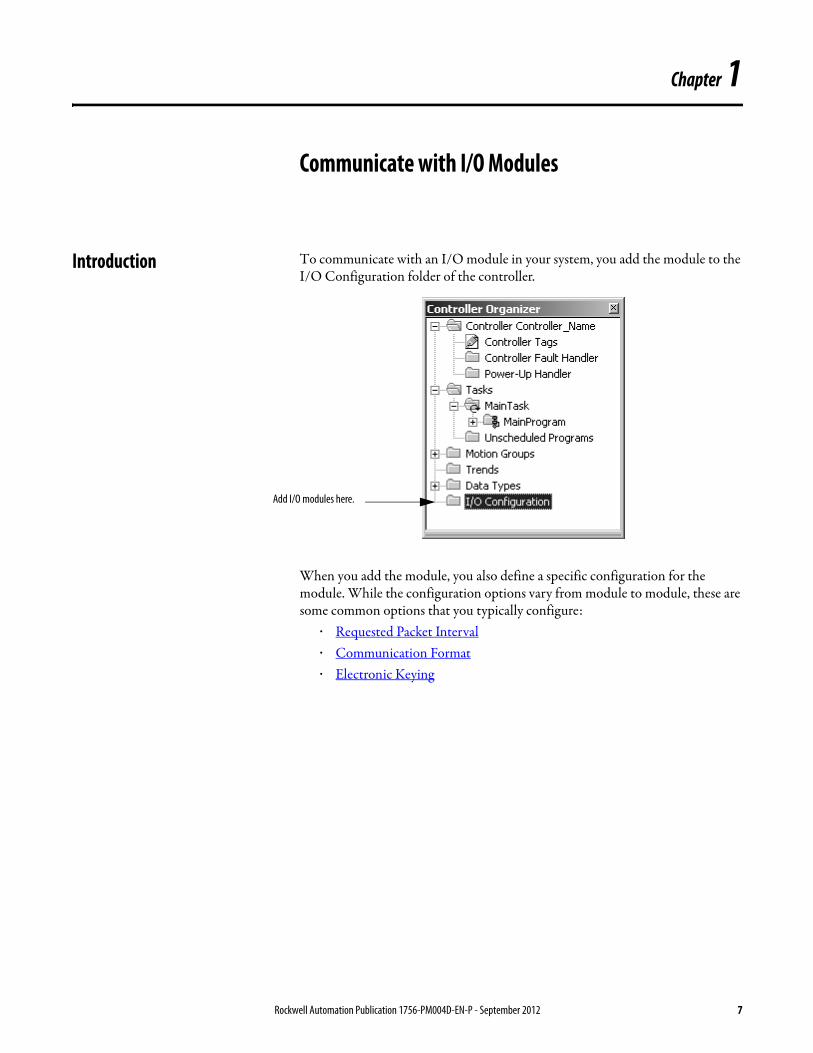
Introduction To communicate with an I/O module in your system, you add the module to the I/O Configuration folder of the controller.
When you add the module, you also define a specific configuration for the module. While the configuration options vary from module to module, these are some common options that you typically configure:
· Requested Packet Interval· Communication Format· Electronic Keying
Add I/O modules here.
Rockwell Automation Publication 1756-PM004D-EN-P - September 2012 7
Chapter 1 Communicate with I/O Modules
Requested Packet Interval The Logix5000 controller uses connections to transmit I/O data.
In Logix5000 controllers, I/O values update at a period that you configure via the I/O configuration folder of the project. The values update asynchronous to the execution of logic. At the specified interval, the controller updates a value independently from the execution of logic.
· Programs within a task access input and output data directly from controller-scoped memory.
· Logic within any task can modify controller-scoped data.· Data and I/O values are asynchronous and can change during the course of
a task’s execution.· An input value referenced at the beginning of a task’s execution can be
different when referenced later.· To prevent an input value from changing during a scan, copy the value to
another tag and use the data from there (buffer the values).
Communication Format The communication format that you choose determines the data structure for the tags that are associated with the module. Many I/O modules support different formats. Each format uses a different data structure. The communication format that you choose also determines:
· Direct or Rack-Optimized Connection.· Ownership.
Term Definition
Connection A communication link between two devices, such as between a controller and an I/O module, PanelView terminal, or another controller.Connections are allocations of resources that provide more reliable communications between devices than unconnected messages. The number of connections that a single controller can have is limited.You indirectly determine the number of connections the controller uses by configuring the controller to communicate with other devices in the system. The following types of communication use connections:
·I/O modules·produced and consumed tags·certain types of Message (MSG) instructions (not all types use a connection)
Requested packet interval (RPI)
The RPI specifies the period at which data updates over a connection. For example, an input module sends data to a controller at the RPI that you assign to the module.
·Typically, you configure an RPI in milliseconds (ms). The range is 0.2 ms (200 microseconds)…750 ms.·If a ControlNet network connects the devices, the RPI reserves a slot in the stream of data flowing across the ControlNet network. The timing of this slot may not coincide with the exact value of the RPI, but the control system guarantees that the data transfers at least as often as the RPI.
ATTENTION: Make sure that data memory contains the appropriate values throughout a task’s execution. You can duplicate or buffer data at the beginning of the scan to provide reference values for your logic.
8 Rockwell Automation Publication 1756-PM004D-EN-P - September 2012
Communicate with I/O Modules Chapter 1
Direct or Rack-Optimized Connection
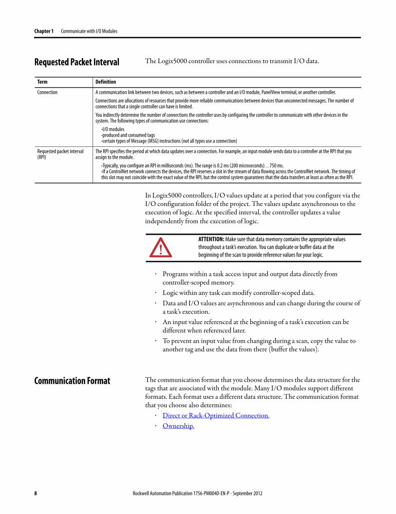
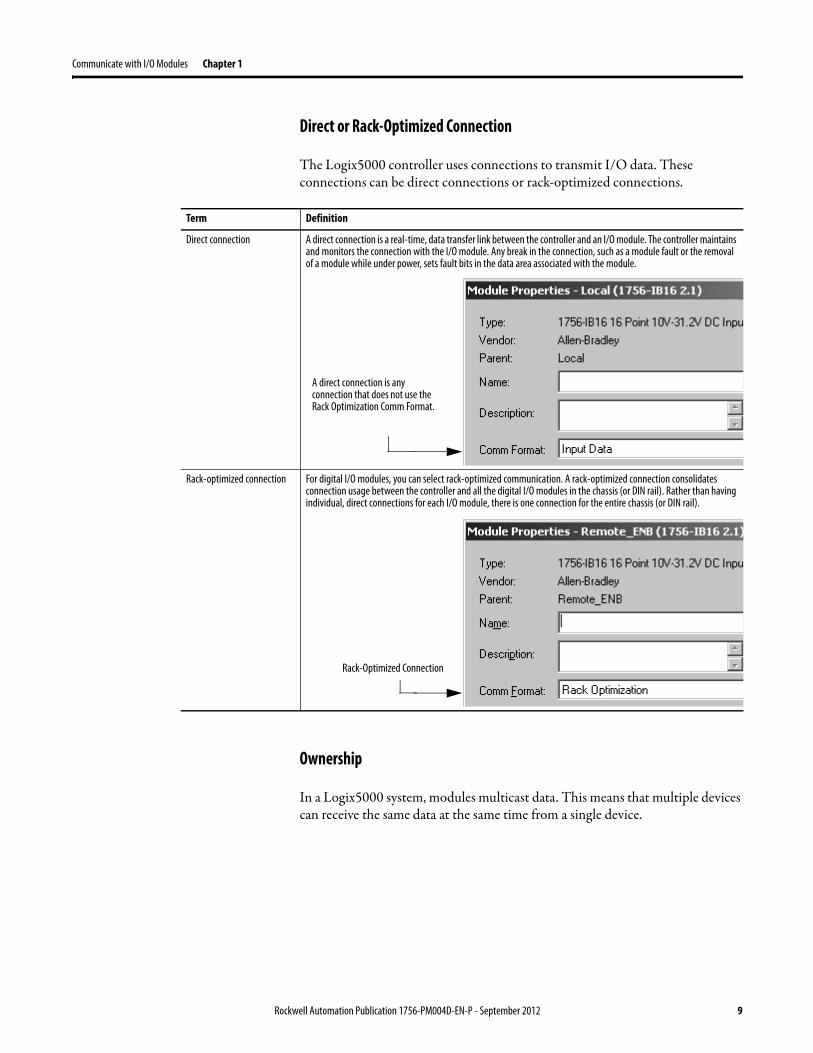
The Logix5000 controller uses connections to transmit I/O data. These connections can be direct connections or rack-optimized connections.
Ownership
In a Logix5000 system, modules multicast data. This means that multiple devices can receive the same data at the same time from a single device.
Term Definition
Direct connection A direct connection is a real-time, data transfer link between the controller and an I/O module. The controller maintains and monitors the connection with the I/O module. Any break in the connection, such as a module fault or the removal of a module while under power, sets fault bits in the data area associated with the module.
Rack-optimized connection For digital I/O modules, you can select rack-optimized communication. A rack-optimized connection consolidates connection usage between the controller and all the digital I/O modules in the chassis (or DIN rail). Rather than having individual, direct connections for each I/O module, there is one connection for the entire chassis (or DIN rail).
A direct connection is any connection that does not use the Rack Optimization Comm Format.
Rack-Optimized Connection
Rockwell Automation Publication 1756-PM004D-EN-P - September 2012 9
Chapter 1 Communicate with I/O Modules
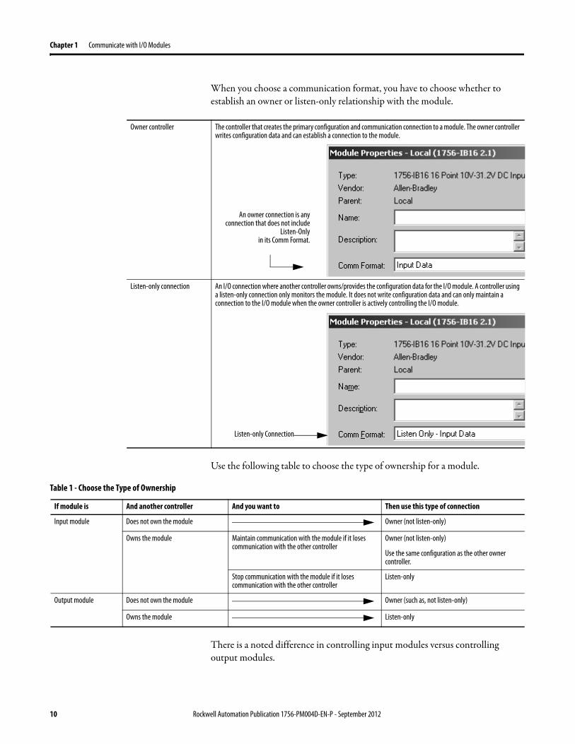
When you choose a communication format, you have to choose whether to establish an owner or listen-only relationship with the module.
Use the following table to choose the type of ownership for a module.
There is a noted difference in controlling input modules versus controlling output modules.
Owner controller The controller that creates the primary configuration and communication connection to a module. The owner controller writes configuration data and can establish a connection to the module.
Listen-only connection An I/O connection where another controller owns/provides the configuration data for the I/O module. A controller using a listen-only connection only monitors the module. It does not write configuration data and can only maintain a connection to the I/O module when the owner controller is actively controlling the I/O module.
An owner connection is any connection that does not include
Listen-Only in its Comm Format.
Listen-only Connection
Table 1 - Choose the Type of Ownership
If module is And another controller And you want to Then use this type of connection
Input module Does not own the module Owner (not listen-only)
Owns the module Maintain communication with the module if it loses communication with the other controller
Owner (not listen-only)
Use the same configuration as the other owner controller.
Stop communication with the module if it loses communication with the other controller
Listen-only
Output module Does not own the module Owner (such as, not listen-only)
Owns the module Listen-only
10 Rockwell Automation Publication 1756-PM004D-EN-P - September 2012
Communicate with I/O Modules Chapter 1
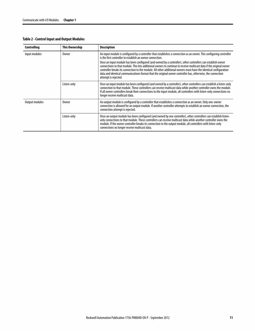
Table 2 - Control Input and Output Modules
Controlling This Ownership Description
Input modules Owner An input module is configured by a controller that establishes a connection as an owner. This configuring controller is the first controller to establish an owner connection.Once an input module has been configured (and owned by a controller), other controllers can establish owner connections to that module. This lets additional owners to continue to receive multicast data if the original owner controller breaks its connection to the module. All other additional owners must have the identical configuration data and identical communications format that the original owner controller has, otherwise, the connection attempt is rejected.
Listen-only Once an input module has been configured (and owned by a controller), other controllers can establish a listen-only connection to that module. These controllers can receive multicast data while another controller owns the module. If all owner controllers break their connections to the input module, all controllers with listen-only connections no longer receive multicast data.
Output modules Owner An output module is configured by a controller that establishes a connection as an owner. Only one-owner connection is allowed for an output module. If another controller attempts to establish an owner connection, the connection attempt is rejected.
Listen-only Once an output module has been configured (and owned by one controller), other controllers can establish listen-only connections to that module. These controllers can receive multicast data while another controller owns the module. If the owner controller breaks its connection to the output module, all controllers with listen-only connections no longer receive multicast data.
Rockwell Automation Publication 1756-PM004D-EN-P - September 2012 11
Chapter 1 Communicate with I/O Modules
Electronic Keying The electronic keying feature automatically compares the expected module, as shown in the Logix Designer I/O Configuration tree, to the physical module before I/O communication begins. You can use electronic keying to help prevent communication to a module that does not match the type and revision expected.
For each module in the I/O Configuration tree, the user-selected keying option determines if, and how, an electronic keying check is performed. Typically, three keying options are available.
·Exact Match·Compatible Module·Disable Keying
You must carefully consider the benefits and implications of each keying option when selecting between them. For some specific module types, fewer options are available.
Electronic keying is based on a set of attributes unique to each product revision. When a Logix5000 controller begins communicating with a module, this set of keying attributes is considered.
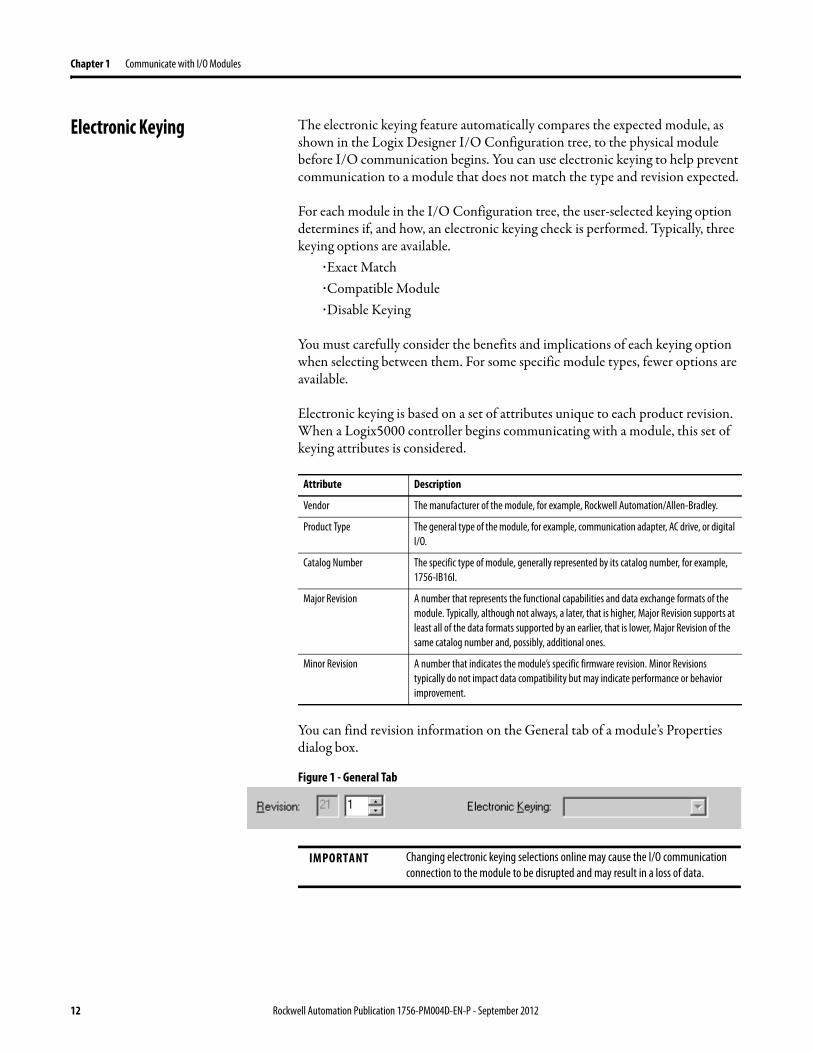
You can find revision information on the General tab of a module’s Properties dialog box.
Figure 1 - General Tab
Attribute Description
Vendor The manufacturer of the module, for example, Rockwell Automation/Allen-Bradley.
Product Type The general type of the module, for example, communication adapter, AC drive, or digital I/O.
Catalog Number The specific type of module, generally represented by its catalog number, for example, 1756-IB16I.
Major Revision A number that represents the functional capabilities and data exchange formats of the module. Typically, although not always, a later, that is higher, Major Revision supports at least all of the data formats supported by an earlier, that is lower, Major Revision of the same catalog number and, possibly, additional ones.
Minor Revision A number that indicates the module’s specific firmware revision. Minor Revisions typically do not impact data compatibility but may indicate performance or behavior improvement.
IMPORTANT Changing electronic keying selections online may cause the I/O communication connection to the module to be disrupted and may result in a loss of data.
12 Rockwell Automation Publication 1756-PM004D-EN-P - September 2012
Communicate with I/O Modules Chapter 1
Exact Match
Exact Match keying requires all keying attributes, that is, Vendor, Product Type, Catalog Number, Major Revision, and Minor Revision, of the physical module and the module created in the software to match precisely in order to establish communication. If any attribute does not match precisely, I/O communication is not permitted with the module or with modules connected through it, as in the case of a communication module.
Use Exact Match keying when you need the system to verify that the module revisions in use are exactly as specified in the project, such as for use in highly-regulated industries. Exact Match keying is also necessary to enable Automatic Firmware Update for the module via the Firmware Supervisor feature from a Logix5000 controller.
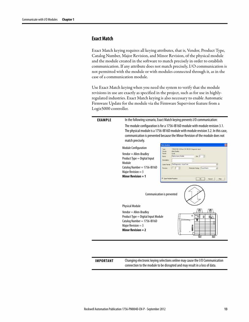
EXAMPLE In the following scenario, Exact Match keying prevents I/O communication:
The module configuration is for a 1756-IB16D module with module revision 3.1. The physical module is a 1756-IB16D module with module revision 3.2. In this case, communication is prevented because the Minor Revision of the module does not match precisely.
IMPORTANT Changing electronic keying selections online may cause the I/O Communication connection to the module to be disrupted and may result in a loss of data.
Module Configuration
Vendor = Allen-BradleyProduct Type = Digital Input ModuleCatalog Number = 1756-IB16DMajor Revision = 3Minor Revision = 1
Physical Module
Vendor = Allen-BradleyProduct Type = Digital Input ModuleCatalog Number = 1756-IB16DMajor Revision = 3Minor Revision = 2
Communication is prevented
Rockwell Automation Publication 1756-PM004D-EN-P - September 2012 13
Chapter 1 Communicate with I/O Modules
Compatible Module
Compatible Module indicates that the module determines whether to accept or reject communication. Different module families, communication adapters, and module types implement the compatibility check differently based on the family capabilities and on prior knowledge of compatible products.
Compatible Module is the default setting. Compatible Module allows the physical module to accept the key of the module configured in the software, provided that the configured module is one the physical module is capable of emulating. The exact level of emulation required is product and revision specific.
With Compatible Module, you can replace a module of a certain Major Revision with one of the same catalog number and the same or later, that is higher, Major Revision. In some cases, the selection makes it possible to use a replacement that is a different catalog number than the original. For example, you can replace a 1756-CNBR module with a 1756-CN2R module.
Release notes for individual modules indicate the specific compatibility details.
When a module is created, the module developers consider the module’s development history to implement capabilities that emulate those of the previous module. However, the developers cannot know future developments. Because of this, when a system is configured, we recommend that you configure your module using the earliest, that is, lowest, revision of the physical module that you believe will be used in the system.
14 Rockwell Automation Publication 1756-PM004D-EN-P - September 2012
Communicate with I/O Modules Chapter 1
By doing this, you can avoid the case of a physical module rejecting the keying request because it is an earlier revision than the one configured in the software.
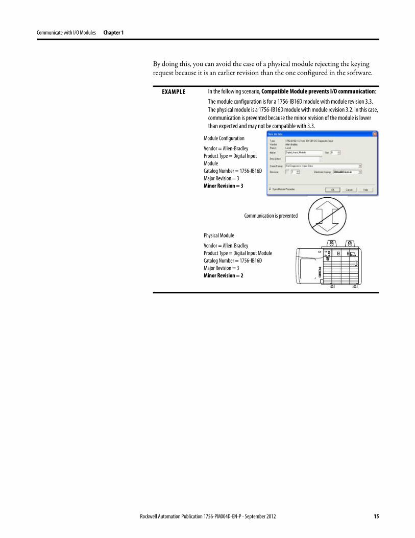
EXAMPLE In the following scenario, Compatible Module prevents I/O communication:
The module configuration is for a 1756-IB16D module with module revision 3.3. The physical module is a 1756-IB16D module with module revision 3.2. In this case, communication is prevented because the minor revision of the module is lower than expected and may not be compatible with 3.3.
Module Configuration
Vendor = Allen-BradleyProduct Type = Digital Input ModuleCatalog Number = 1756-IB16DMajor Revision = 3Minor Revision = 3
Physical Module
Vendor = Allen-BradleyProduct Type = Digital Input ModuleCatalog Number = 1756-IB16DMajor Revision = 3Minor Revision = 2
Communication is prevented
Rockwell Automation Publication 1756-PM004D-EN-P - September 2012 15
Chapter 1 Communicate with I/O Modules
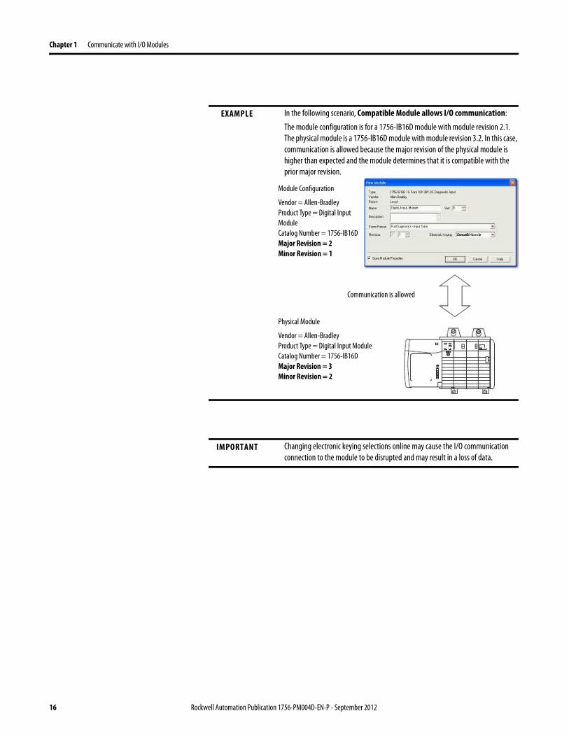
EXAMPLE In the following scenario, Compatible Module allows I/O communication:
The module configuration is for a 1756-IB16D module with module revision 2.1. The physical module is a 1756-IB16D module with module revision 3.2. In this case, communication is allowed because the major revision of the physical module is higher than expected and the module determines that it is compatible with the prior major revision.
IMPORTANT Changing electronic keying selections online may cause the I/O communication connection to the module to be disrupted and may result in a loss of data.
Module Configuration
Vendor = Allen-BradleyProduct Type = Digital Input ModuleCatalog Number = 1756-IB16DMajor Revision = 2Minor Revision = 1
Physical Module
Vendor = Allen-BradleyProduct Type = Digital Input ModuleCatalog Number = 1756-IB16DMajor Revision = 3Minor Revision = 2
Communication is allowed
16 Rockwell Automation Publication 1756-PM004D-EN-P - September 2012
Communicate with I/O Modules Chapter 1
Disabled Keying
Disabled Keying indicates the keying attributes are not considered when attempting to communicate with a module. Other attributes, such as data size and format, are considered and must be acceptable before I/O communication is established. With Disabled Keying, I/O communication may occur with a module other than the type specified in the I/O Configuration tree with unpredictable results. We generally do not recommend using Disabled Keying.
If you use Disabled Keying, you must take full responsibility for understanding whether the module being used can fulfill the functional requirements of the application.
ATTENTION: Be extremely cautious when using Disabled Keying; if used incorrectly, this option can lead to personal injury or death, property damage, or economic loss.
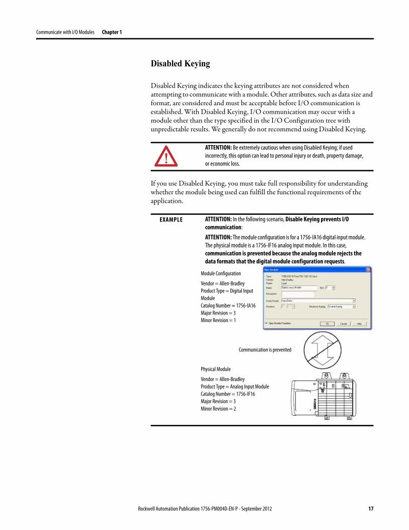
EXAMPLE ATTENTION: In the following scenario, Disable Keying prevents I/O communication:
ATTENTION: The module configuration is for a 1756-IA16 digital input module. The physical module is a 1756-IF16 analog input module. In this case, communication is prevented because the analog module rejects the data formats that the digital module configuration requests.
Module Configuration
Vendor = Allen-BradleyProduct Type = Digital Input ModuleCatalog Number = 1756-IA16Major Revision = 3Minor Revision = 1
Physical Module
Vendor = Allen-BradleyProduct Type = Analog Input ModuleCatalog Number = 1756-IF16Major Revision = 3Minor Revision = 2
Communication is prevented
Rockwell Automation Publication 1756-PM004D-EN-P - September 2012 17
Chapter 1 Communicate with I/O Modules
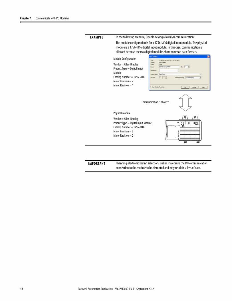
EXAMPLE In the following scenario, Disable Keying allows I/O communication:
The module configuration is for a 1756-IA16 digital input module. The physical module is a 1756-IB16 digital input module. In this case, communication is allowed because the two digital modules share common data formats.
IMPORTANT Changing electronic keying selections online may cause the I/O communication connection to the module to be disrupted and may result in a loss of data.
Module Configuration
Vendor = Allen-BradleyProduct Type = Digital Input ModuleCatalog Number = 1756-IA16Major Revision = 2Minor Revision = 1
Physical Module
Vendor = Allen-BradleyProduct Type = Digital Input ModuleCatalog Number = 1756-IB16Major Revision = 3Minor Revision = 2
Communication is allowed
18 Rockwell Automation Publication 1756-PM004D-EN-P - September 2012
Communicate with I/O Modules Chapter 1
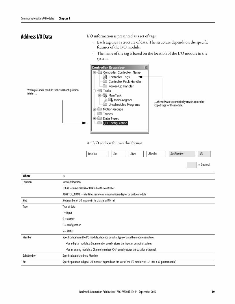
Address I/O Data I/O information is presented as a set of tags.· Each tag uses a structure of data. The structure depends on the specific
features of the I/O module.· The name of the tag is based on the location of the I/O module in the
system.
An I/O address follows this format:
When you add a module to the I/O Configuration folder…
…the software automatically creates controller-scoped tags for the module.
Location :Slot :Type .Member .SubMember .Bit
= Optional
Where Is
Location Network location
LOCAL = same chassis or DIN rail as the controller
ADAPTER_NAME = identifies remote communication adapter or bridge module
Slot Slot number of I/O module in its chassis or DIN rail
Type Type of data
I = input
O = output
C = configuration
S = status
Member Specific data from the I/O module; depends on what type of data the module can store.
·For a digital module, a Data member usually stores the input or output bit values.
·For an analog module, a Channel member (CH#) usually stores the data for a channel.
SubMember Specific data related to a Member.
Bit Specific point on a digital I/O module; depends on the size of the I/O module (0…31 for a 32-point module)
Rockwell Automation Publication 1756-PM004D-EN-P - September 2012 19
Chapter 1 Communicate with I/O Modules
Buffer I/O Buffering is a technique that logic does not directly reference or manipulate the tags of real I/O devices. Instead, the logic uses a copy of the I/O data. Buffer I/O in the following situations:
· To prevent an input or output value from changing during the execution of a program. (I/O updates asynchronous to the execution of logic.)
· To copy an input or output tag to a member of a structure or element of an array.
Follow these steps to buffer I/O.
1. On the rung before the logic for the function, copy or move the data from the required input tags to their corresponding buffer tags.
2. In the logic of the function, reference the buffer tags.
3. On the rung after the function, copy the data from the buffer tags to the corresponding output tags.
20 Rockwell Automation Publication 1756-PM004D-EN-P - September 2012
Communicate with I/O Modules Chapter 1
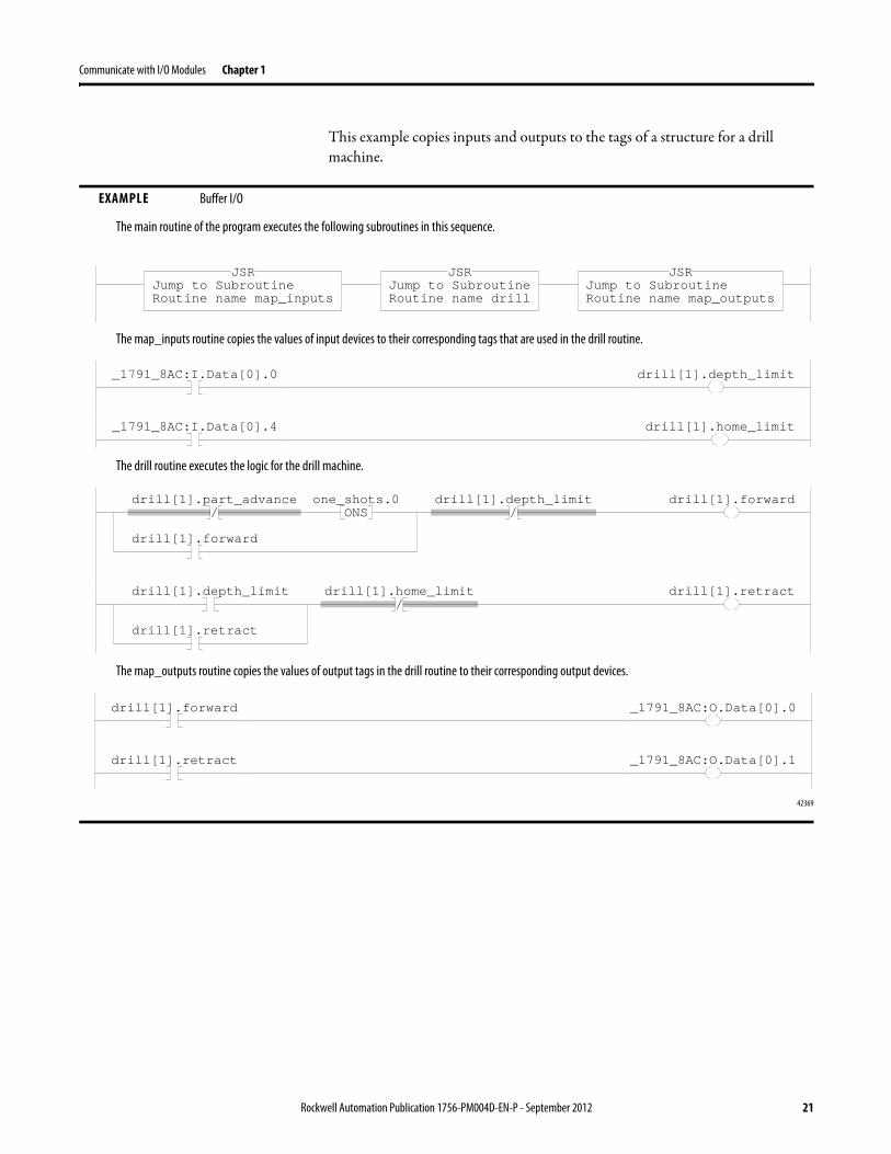
This example copies inputs and outputs to the tags of a structure for a drill machine.
EXAMPLE Buffer I/O
The main routine of the program executes the following subroutines in this sequence.
The map_inputs routine copies the values of input devices to their corresponding tags that are used in the drill routine.
The drill routine executes the logic for the drill machine.
The map_outputs routine copies the values of output tags in the drill routine to their corresponding output devices.
42369
Jump to SubroutineRoutine name map_inputs
JSRJump to SubroutineRoutine name drill
JSRJump to SubroutineRoutine name map_outputs
JSR
_1791_8AC:I.Data[0].0 drill[1].depth_limit
_1791_8AC:I.Data[0].4 drill[1].home_limit
/drill[1].part_advance
ONSone_shots.0
drill[1].forward
/drill[1].depth_limit drill[1].forward
drill[1].depth_limit
drill[1].retract
/drill[1].home_limit drill[1].retract
drill[1].forward _1791_8AC:O.Data[0].0
drill[1].retract _1791_8AC:O.Data[0].1
Rockwell Automation Publication 1756-PM004D-EN-P - September 2012 21
Chapter 1 Communicate with I/O Modules
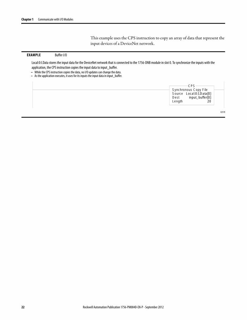
This example uses the CPS instruction to copy an array of data that represent the input devices of a DeviceNet network.
EXAMPLE Buffer I/O
Local:0:I.Data stores the input data for the DeviceNet network that is connected to the 1756-DNB module in slot 0. To synchronize the inputs with the application, the CPS instruction copies the input data to input_buffer.
– While the CPS instruction copies the data, no I/O updates can change the data.– As the application executes, it uses for its inputs the input data in input_buffer.
42578
Synchronous Copy FileSource Local:0:I.Data[0]Dest input_buffer[0]Length 20
CPS
22 Rockwell Automation Publication 1756-PM004D-EN-P - September 2012
Chapter 2
Organizing Tags
Introduction With a Logix5000controller, you use a tag (alphanumeric name) to address data (variables).
The controller uses the tag name internally and does not need to cross-reference a physical address.
· In conventional programmable controllers, a physical address identifies each item of data.– Addresses follow a fixed, numeric format that depends on the type of
data, such as N7:8, F8:3.– Symbols are required to make logic easier to interpret.
· In Logix5000 controllers, there is no fixed, numeric format. The tag name itself identifies the data. This lets you:– organize your data to mirror your machinery.– document (through tag names) your application as you develop it.
Term Definition
Tag A text-based name for an area of the controller’s memory where data is stored.
·Tags are the basic mechanism for allocating memory, referencing data from logic, and monitoring data.·The minimum memory allocation for a tag is four bytes. ·When you create a tag that stores data that requires less than four bytes, the controller allocates four bytes, but the data only fills the part it needs.
Rockwell Automation Publication 1756-PM004D-EN-P - September 2012 23
Chapter 2 Organizing Tags
Tag Type
The tag type defines how the tag operates within your project.
If you plan to use produced or consumed tags, you must follow additional guidelines as you organize your tags.
See the Logix5000 Controllers Produced and Consumed Tags Programming Manual, publication 1756-PM011.
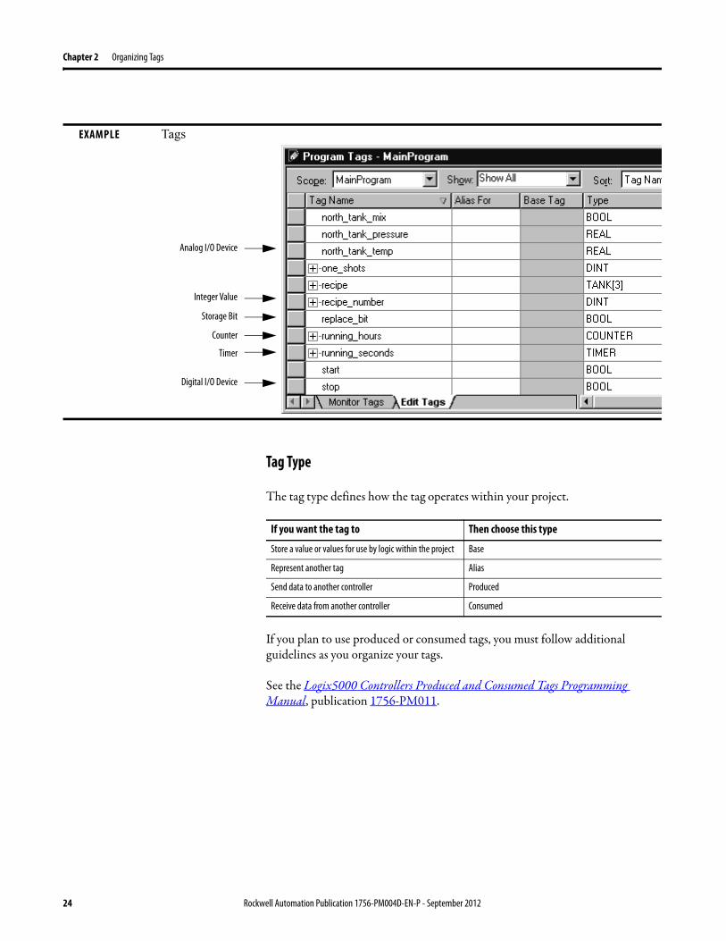
EXAMPLE Tags
Digital I/O Device
Analog I/O Device
Integer Value
Storage Bit
Counter
Timer
If you want the tag to Then choose this type
Store a value or values for use by logic within the project Base
Represent another tag Alias
Send data to another controller Produced
Receive data from another controller Consumed
24 Rockwell Automation Publication 1756-PM004D-EN-P - September 2012
Organizing Tags Chapter 2
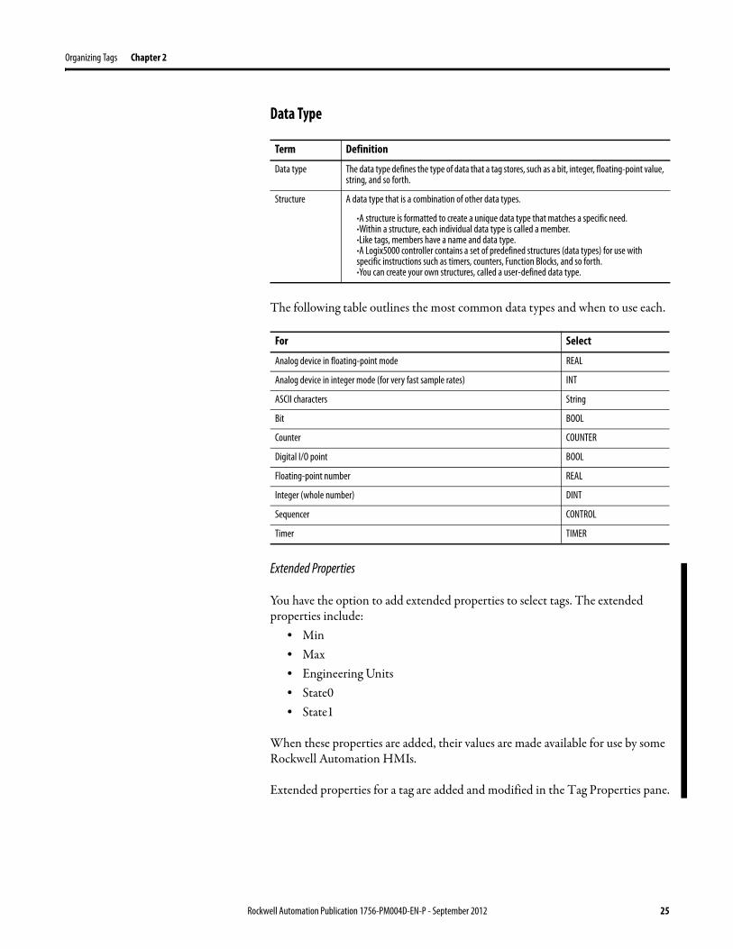
Data Type
The following table outlines the most common data types and when to use each.
Extended Properties
You have the option to add extended properties to select tags. The extended properties include:
• Min• Max • Engineering Units • State0 • State1
When these properties are added, their values are made available for use by some Rockwell Automation HMIs.
Extended properties for a tag are added and modified in the Tag Properties pane.
Term Definition
Data type The data type defines the type of data that a tag stores, such as a bit, integer, floating-point value, string, and so forth.
Structure A data type that is a combination of other data types.
·A structure is formatted to create a unique data type that matches a specific need.·Within a structure, each individual data type is called a member.·Like tags, members have a name and data type.·A Logix5000 controller contains a set of predefined structures (data types) for use with specific instructions such as timers, counters, Function Blocks, and so forth.·You can create your own structures, called a user-defined data type.
For Select
Analog device in floating-point mode REAL
Analog device in integer mode (for very fast sample rates) INT
ASCII characters String
Bit BOOL
Counter COUNTER
Digital I/O point BOOL
Floating-point number REAL
Integer (whole number) DINT
Sequencer CONTROL
Timer TIMER
Rockwell Automation Publication 1756-PM004D-EN-P - September 2012 25
Chapter 2 Organizing Tags
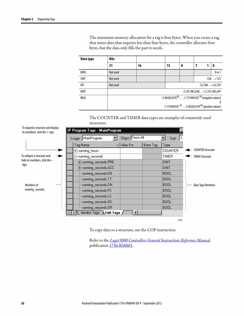
The minimum memory allocation for a tag is four bytes. When you create a tag that stores data that requires less than four bytes, the controller allocates four bytes, but the data only fills the part it needs.
The COUNTER and TIMER data types are examples of commonly used structures.
To copy data to a structure, use the COP instruction.
Refer to the Logix5000 Controllers General Instructions Reference Manual, publication 1756-RM003.
Data type Bits
31 16 15 8 7 1 0
BOOL Not used 0 or 1
SINT Not used -128…+127
INT Not used -32,768…+32,767
DINT -2,147,483,648…+2,147,483,647
REAL -3.40282347E38 …-1.17549435E-38 (negative values)0
1.17549435E-38 …3.40282347E38 (positive values)
42365
To expand a structure and display its members, click the + sign.
To collapse a structure and hide its members, click the – sign.
COUNTER Structure
TIMER Structure
Data Type MembersMembers of running_seconds
26 Rockwell Automation Publication 1756-PM004D-EN-P - September 2012
Organizing Tags Chapter 2
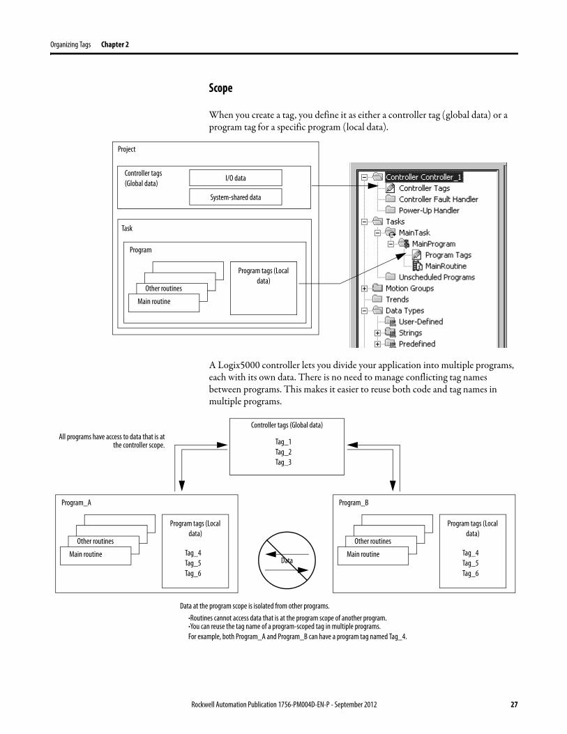
Scope
When you create a tag, you define it as either a controller tag (global data) or a program tag for a specific program (local data).
A Logix5000 controller lets you divide your application into multiple programs, each with its own data. There is no need to manage conflicting tag names between programs. This makes it easier to reuse both code and tag names in multiple programs.
Controller tags (Global data)
Task
Program
Project
Other routines
Main routine
I/O data
Program tags (Local data)
System-shared data
Controller tags (Global data)
Program_A
Other routines
Main routine Tag_4Tag_5Tag_6
Program tags (Local data)
Tag_1Tag_2Tag_3
Program_B
Other routines
Main routine Tag_4Tag_5Tag_6
Program tags (Local data)
Data at the program scope is isolated from other programs.·Routines cannot access data that is at the program scope of another program.·You can reuse the tag name of a program-scoped tag in multiple programs. For example, both Program_A and Program_B can have a program tag named Tag_4.
Data
All programs have access to data that is at the controller scope.
Rockwell Automation Publication 1756-PM004D-EN-P - September 2012 27
Chapter 2 Organizing Tags
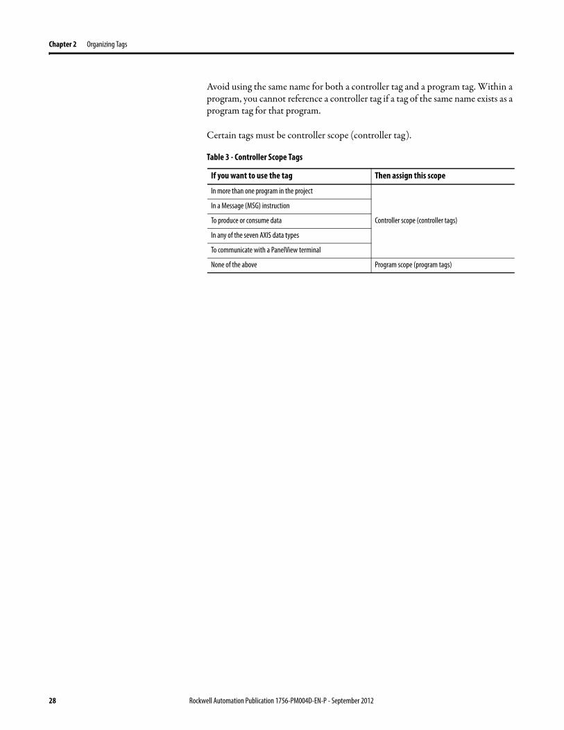
Avoid using the same name for both a controller tag and a program tag. Within a program, you cannot reference a controller tag if a tag of the same name exists as a program tag for that program.
Certain tags must be controller scope (controller tag).
Table 3 - Controller Scope Tags
If you want to use the tag Then assign this scope
In more than one program in the project
Controller scope (controller tags)
In a Message (MSG) instruction
To produce or consume data
In any of the seven AXIS data types
To communicate with a PanelView terminal
None of the above Program scope (program tags)
28 Rockwell Automation Publication 1756-PM004D-EN-P - September 2012
Organizing Tags Chapter 2
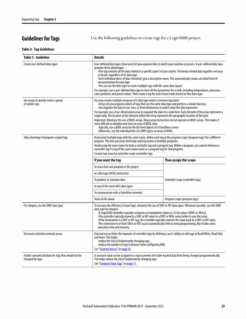
Guidelines for Tags Use the following guidelines to create tags for a Logix5000 project.
Table 4 - Tag Guidelines
Table 5 - Guideline Details
Create user-defined data types User-defined data types (structures) let you organize data to match your machine or process. A user-defined data type provides these advantages:
·One tag contains all the data related to a specific aspect of your system. This keeps related data together and easy to locate, regardless of its data type.·Each individual piece of data (member) gets a descriptive name. This automatically creates an initial level of documentation for your logic.·You can use the data type to create multiple tags with the same data layout.
For example, use a user-defined data type to store all the parameters for a tank, including temperatures, pressures, valve positions, and preset values. Then create a tag for each of your tanks based on that data type.
Use arrays to quickly create a group
of similar tagsAn array creates multiple instances of a data type under a common tag name.
·Arrays let you organize a block of tags that use the same data type and perform a similar function.·You organize the data in one, two, or three dimensions to match what the data represents.
For example, use a two-dimensional array to organize the data for a tank farm. Each element of the array represents a single tank. The location of the element within the array represents the geographic location of the tank.Important: Minimize the use of BOOL arrays. Many array instructions do not operate on BOOL arrays. This makes it more difficult to initialize and clear an array of BOOL data.
·Typically, use a BOOL array for the bit-level objects of a PanelView screen.·Otherwise, use the individual bits of a DINT tag or an array of DINTs.
Take advantage of program-scoped tags If you want multiple tags with the same name, define each tag at the program scope (program tags) for a different program. This lets you reuse both logic and tag names in multiple programs.Avoid using the same name for both a controller tag and a program tag. Within a program, you cannot reference a controller tag if a tag of the same name exists as a program tag for that program.Certain tags must be controller scope (controller tag).
If you want the tag Then assign this scope
In more than one program in the project
Controller scope (controller tags)
In a Message (MSG) instruction
To produce or consume data
In any of the seven AXIS data types
To communicate with a PanelView terminal
None of the above Program scope (program tags)
For integers, use the DINT data type To increase the efficiency of your logic, minimize the use of SINT or INT data types. Whenever possible, use the DINT data type for integers.
·A Logix5000 controller typically compares or manipulates values as 32-bit values (DINTs or REALs).·The controller typically converts a SINT or INT value to a DINT or REAL value before it uses the value.·If the destination is a SINT or INT tag, the controller typically converts the value back to a SINT or INT value. ·The conversion to or from SINTs or INTs occurs automatically with no extra programming. But it takes extra execution time and memory.
Use most restrictive external access External access limits the exposure of controller tags by defining a user’s ability to edit tags to Read/Write, Read Only and None. This helps:
·reduce the risk of inadvertently changing tags.·reduce the number of tags to browse when configuring HMI.
See “External Access” on page 65.
Enable constant attribute for tags that should not be changed by logic
A constant value can be assigned to a tag to prevent the table-backed data from being changed programmatically. This helps reduce the risk of inadvertently changing tags.See “Constant Value Tags” on page 77.
Rockwell Automation Publication 1756-PM004D-EN-P - September 2012 29
Chapter 2 Organizing Tags
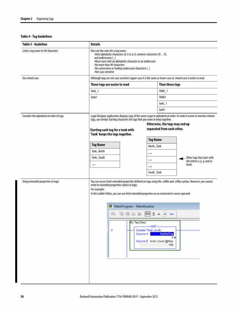
Limit a tag name to 40 characters Here are the rules for a tag name:·Only alphabetic characters (A-Z or a-z), numeric characters (0…9), and underscores (_)·Must start with an alphabetic character or an underscore·No more than 40 characters·No consecutive or trailing underscore characters (_)·Not case sensitive
Use mixed case Although tags are not case sensitive (upper case A is the same as lower case a), mixed case is easier to read.
These tags are easier to read Than these tags
Tank_1 TANK_1
Tank1 TANK1
tank_1
tank1
Consider the alphabetical order of tags Logix Designer application displays tags of the same scope in alphabetical order. To make it easier to monitor related tags, use similar starting characters for tags that you want to keep together.
Using extended properties in logic You can access limit extended properties defined on tags using the .@Min and .@Max syntax. However, you cannot write to extended properties values in logic.For example:In the Ladder Editor, you can use limit extended properties on an instruction’s source operand.
Table 4 - Tag Guidelines
Table 5 - Guideline Details
Starting each tag for a tank with ‘Tank’ keeps the tags together.
Tag Name
Tank_North
Tank_South
…
Otherwise, the tags may end up separated from each other.
Tag Name
North_Tank
…
…
…
South_Tank
Other tags that start with the letters o, p, q, and so forth.
30 Rockwell Automation Publication 1756-PM004D-EN-P - September 2012
Organizing Tags Chapter 2
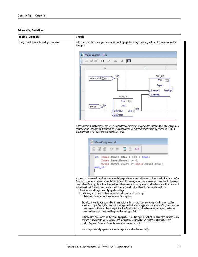
Using extended properties in logic (continued) In the Function Block Editor, you can access extended properties in logic by wiring an Input Reference to a block’s input pins.
In the Structured Text Editor, you can access limit extended properties in logic on the right hand side of an assignment operation or in a comparison statement. You can also access limit extended properties in logic when you embed structured text in the Sequential Function Chart Editor.
You need to know which tags have limit extended properties associated with them as there is no indication in the Tag Browser that extended properties are defined for a tag. If however, you try to use extended properties that have not been defined for a tag, the editors show a visual indication (that is: a rung error in Ladder Logic, a verification error X in Function Block Diagrams, and the error underlined in Structured Text) and the routine does not verify.
·Restrictions to adding extended properties in logicThe following restrictions apply when you use extended properties in logic.· Extended properties must be used as an input operand
Extended properties can be used on an instruction as long as the input (source) operand is a non-boolean atomic data type. That is, if an instruction has operands whose data type is non-atomic or BOOL, limit extended properties can not be used. For example, the ALMD instruction in Ladder Logic does not support extended properties because its configurable operands are of type BOOL.
In the Ladder Editor, when limit extended properties is used in logic, the value field associated with the source operand is unavailable. You can change the tag's extended properties only in the Tag Properties Pane.· Alias Tags with Extended Properties cannot be accessed in Logic
If alias tag extended properties are used in logic, the routine does not verify.
Table 4 - Tag Guidelines
Table 5 - Guideline Details
Rockwell Automation Publication 1756-PM004D-EN-P - September 2012 31
Chapter 2 Organizing Tags
Using extended properties in logic (continued) ·Array Tags are constrainedA constraint on array tags apply if the array tag uses indirect addressing to access limit extended properties. If an array tag is using indirect addressing to access limit extended properties in logic, the following conditions apply. – If the Array Tag has limit extended properties configured, the extended properties are applied to any array
element that does not explicitly have that particular extended property configured. For example, if the MyArray has Max configured to 100, then any element of the array that does not have Max configured inherits the value of 100 when being used in logic. However, it will not be visible to you that the value inherited from MyArray is configured in the tag properties.
– At least one array element must have specific limit extended property configured for indirectly referenced array logic to verify. For example, if MyArray[x].@Max is being used in logic, at least one array element of MyArray[] must have Max extended property configured if Max is not configured by MyArray. If this is not done, if you attempt to access Max in logic on MyArray in logic, the routine does not verify.
– Under the following circumstances a data type default value is going to be used: - Array is accessed programmatically with indirect reference. - Array tag does not have the extended property configured. - Member of array does not have the extended property configured. For example for Array of SINT type, when max limit is called in logic for a member, the value 127 will be used.
·Removing Extended PropertiesYou cannot remove extended properties that are accessed in logic when the project is online with the controller. The Max and Min check boxes in the Extended Properties box in the Tag Editor are unavailable. You have to go offline in order to remove the extended properties.Removing extended properties in logic on structure tags is unavailable at the tag level. For example, if MyUDTTag has 2 members, Mem1 being a DINT and the Mem2 being a SINT, if you define limit extended properties in Logic on both members, but are only accessing Max extended properties on Mem1, the Max check box is unavailable in the Extended Properties box in the Tag Properties Pane for both members. You are not able to remove the Max extended properties for MyUDTTag .Mem2 online. The same applies for Array tags. If limit extended properties is define on an array element and that element is accessed in logic, then limit extended properties cannot be removed from any of the array elements.
Table 4 - Tag Guidelines
Table 5 - Guideline Details
32 Rockwell Automation Publication 1756-PM004D-EN-P - September 2012
Organizing Tags Chapter 2
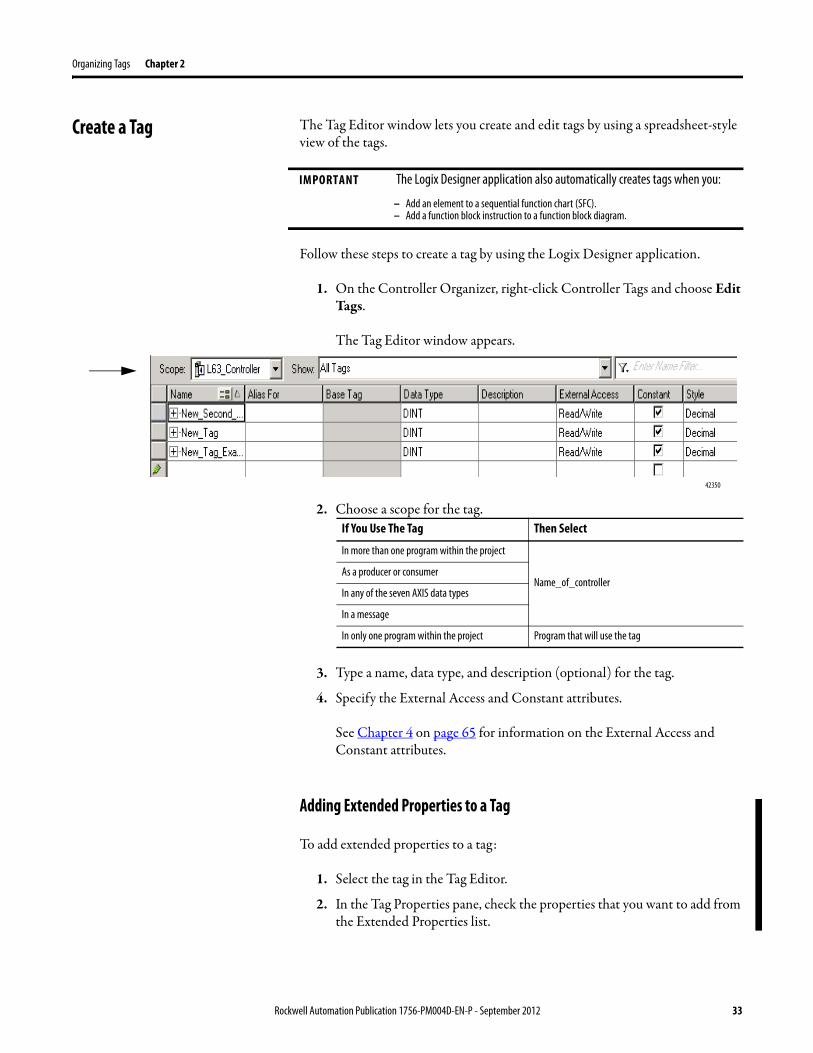
Create a Tag The Tag Editor window lets you create and edit tags by using a spreadsheet-style view of the tags.
Follow these steps to create a tag by using the Logix Designer application.
1. On the Controller Organizer, right-click Controller Tags and choose Edit Tags.
The Tag Editor window appears.
2. Choose a scope for the tag.
3. Type a name, data type, and description (optional) for the tag.
4. Specify the External Access and Constant attributes.
See Chapter 4 on page 65 for information on the External Access and Constant attributes.
Adding Extended Properties to a Tag
To add extended properties to a tag:
1. Select the tag in the Tag Editor.
2. In the Tag Properties pane, check the properties that you want to add from the Extended Properties list.
IMPORTANT The Logix Designer application also automatically creates tags when you:
– Add an element to a sequential function chart (SFC).– Add a function block instruction to a function block diagram.
42350
If You Use The Tag Then Select
In more than one program within the project
Name_of_controllerAs a producer or consumer
In any of the seven AXIS data types
In a message
In only one program within the project Program that will use the tag
Rockwell Automation Publication 1756-PM004D-EN-P - September 2012 33
Chapter 2 Organizing Tags
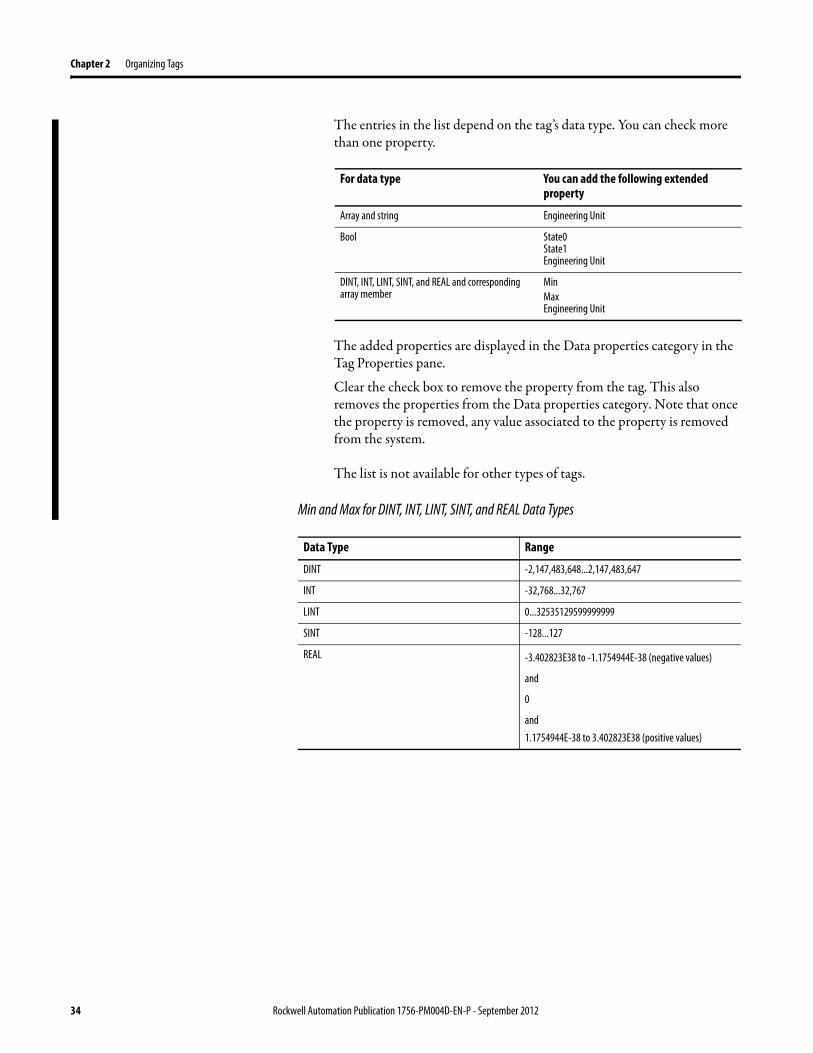
The entries in the list depend on the tag’s data type. You can check more than one property.
The added properties are displayed in the Data properties category in the Tag Properties pane.
Clear the check box to remove the property from the tag. This also removes the properties from the Data properties category. Note that once the property is removed, any value associated to the property is removed from the system.
The list is not available for other types of tags.
Min and Max for DINT, INT, LINT, SINT, and REAL Data Types
For data type You can add the following extended property
Array and string Engineering Unit
Bool State0State1Engineering Unit
DINT, INT, LINT, SINT, and REAL and corresponding array member
MinMaxEngineering Unit
Data Type Range
DINT -2,147,483,648...2,147,483,647
INT -32,768...32,767
LINT 0...32535129599999999
SINT -128...127
REAL -3.402823E38 to -1.1754944E-38 (negative values)
and
0
and1.1754944E-38 to 3.402823E38 (positive values)
34 Rockwell Automation Publication 1756-PM004D-EN-P - September 2012
Organizing Tags Chapter 2
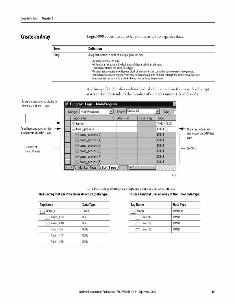
Create an Array Logix5000 controllers also let you use arrays to organize data.
A subscript (s) identifies each individual element within the array. A subscript starts at 0 and extends to the number of elements minus 1 (zero based).
The following example compares a structure to an array.
Term Definition
Array A tag that contains a block of multiple pieces of data.
·An array is similar to a file.·Within an array, each individual piece of data is called an element.·Each element uses the same data type.·An array tag occupies a contiguous block of memory in the controller, each element in sequence.·You can use array and sequencer instructions to manipulate or index through the elements of an array.·You organize the data into a block of one, two, or three dimensions.
42367
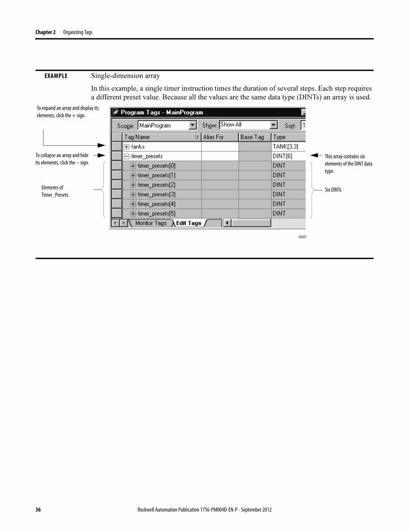
To expand an array and display its elements, click the + sign.
To collapse an array and hide its elements, click the – sign.
This array contains six elements of the DINT data type.
Six DINTsElements of Timer_Presets
This is a tag that uses the Timer structure (data type).
Tag Name Data Type
Timer_1 TIMER
Timer_1.PRE DINT
Timer_1.ACC DINT
Timer_1.EN BOOL
Timer_1.TT BOOL
Timer_1.DN BOOL
−
+
+
This is a tag that uses an array of the Timer data type.
Tag Name Data Type
Timers TIMER[3]
Timer[0] TIMER
Timer[1] TIMER
Timer[2] TIMER
−
+
+
+
Rockwell Automation Publication 1756-PM004D-EN-P - September 2012 35
Chapter 2 Organizing Tags
EXAMPLE Single-dimension array
In this example, a single timer instruction times the duration of several steps. Each step requires
a different preset value. Because all the values are the same data type (DINTs) an array is used.
42367
To expand an array and display its elements, click the + sign.
To collapse an array and hide its elements, click the – sign.
This array contains six elements of the DINT data type.
Six DINTsElements of Timer_Presets
36 Rockwell Automation Publication 1756-PM004D-EN-P - September 2012
Organizing Tags Chapter 2
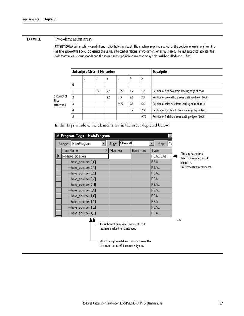
EXAMPLE Two-dimension array
ATTENTION: A drill machine can drill one…five holes in a book. The machine requires a value for the position of each hole from the leading edge of the book. To organize the values into configurations, a two-dimension array is used. The first subscript indicates the hole that the value corresponds and the second subscript indications how many holes will be drilled (one…five).
In the Tags window, the elements are in the order depicted below.
Subscript of Second Dimension Description
0 1 2 3 4 5
Subscript of First Dimension
0
1 1.5 2.5 1.25 1.25 1.25 Position of first hole from leading edge of book
2 8.0 5.5 3.5 3.5 Position of second hole from leading edge of book
3 9.75 7.5 5.5 Position of third hole from leading edge of book
4 9.75 7.5 Position of fourth hole from leading edge of book
5 9.75 Position of fifth hole from leading edge of book
42367
The rightmost dimension increments to its maximum value then starts over.
This array contains a two-dimensional grid of elements, six elements x six elements.
When the rightmost dimension starts over, the dimension to the left increments by one.
Rockwell Automation Publication 1756-PM004D-EN-P - September 2012 37
Chapter 2 Organizing Tags
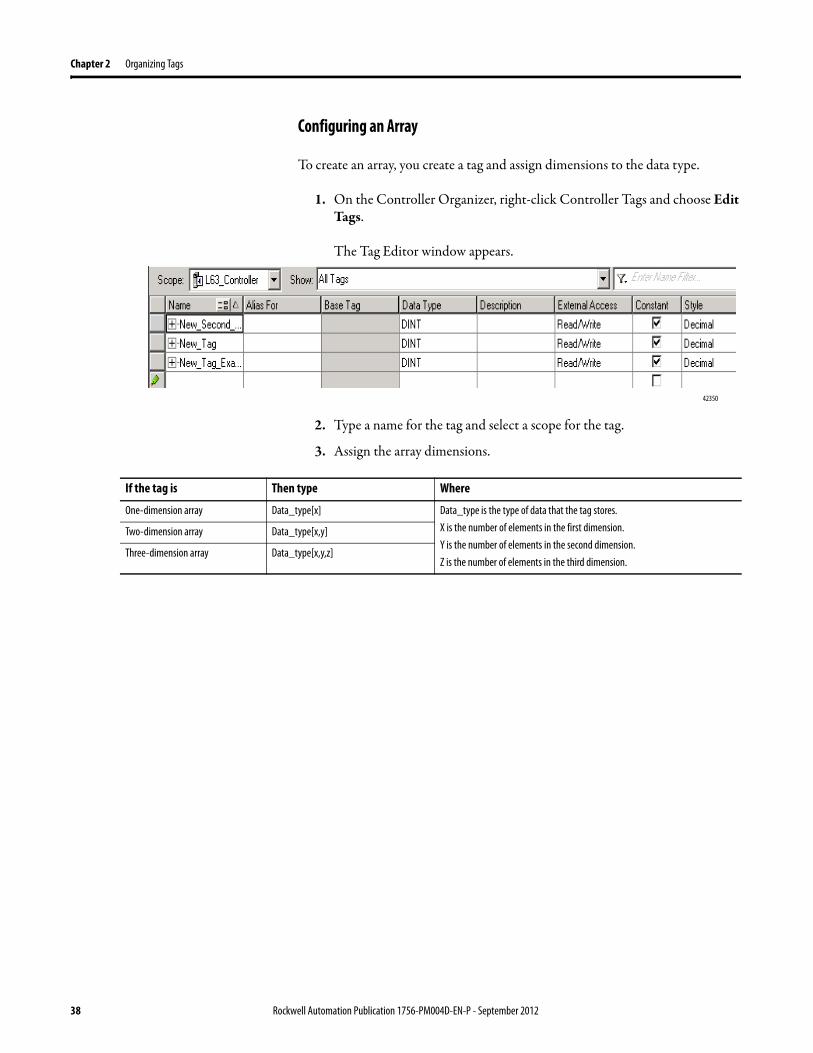
Configuring an Array
To create an array, you create a tag and assign dimensions to the data type.
1. On the Controller Organizer, right-click Controller Tags and choose Edit Tags.
The Tag Editor window appears.
2. Type a name for the tag and select a scope for the tag.
3. Assign the array dimensions.
42350
If the tag is Then type Where
One-dimension array Data_type[x] Data_type is the type of data that the tag stores.X is the number of elements in the first dimension. Y is the number of elements in the second dimension.Z is the number of elements in the third dimension.
Two-dimension array Data_type[x,y]
Three-dimension array Data_type[x,y,z]
38 Rockwell Automation Publication 1756-PM004D-EN-P - September 2012
Organizing Tags Chapter 2
Creating a User-defined Data Type
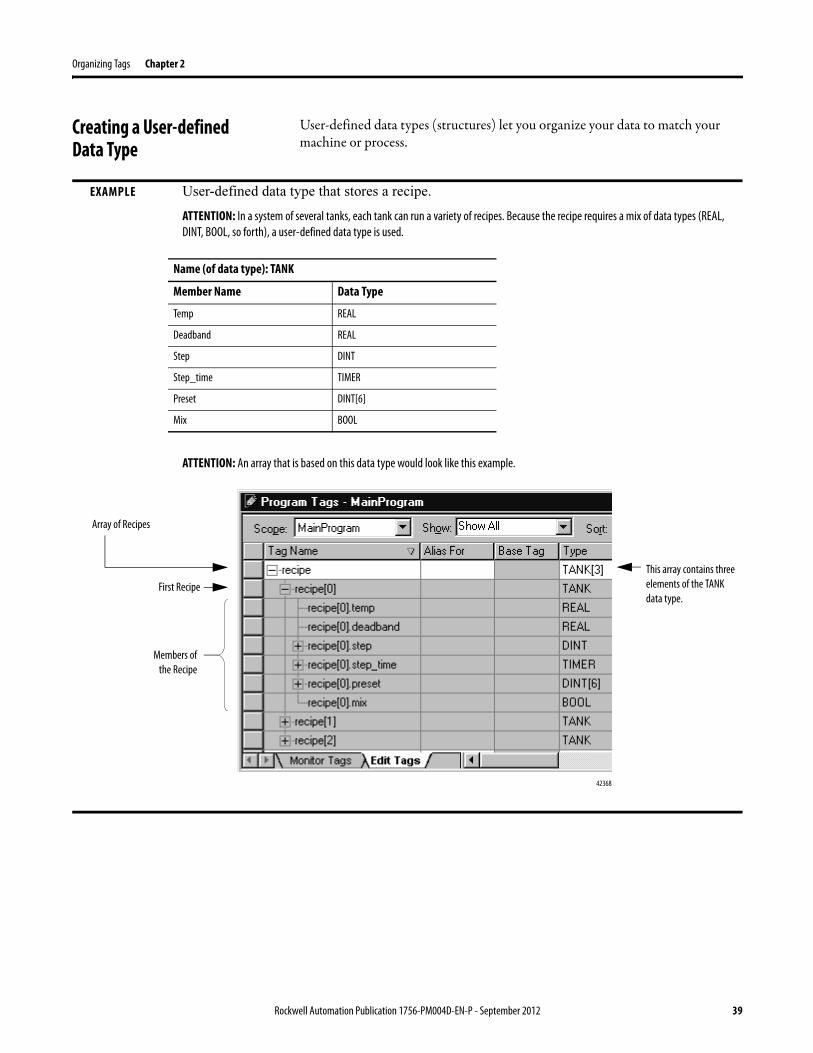
User-defined data types (structures) let you organize your data to match your machine or process.
EXAMPLE User-defined data type that stores a recipe.
ATTENTION: In a system of several tanks, each tank can run a variety of recipes. Because the recipe requires a mix of data types (REAL, DINT, BOOL, so forth), a user-defined data type is used.
ATTENTION: An array that is based on this data type would look like this example.
Name (of data type): TANK
Member Name Data Type
Temp REAL
Deadband REAL
Step DINT
Step_time TIMER
Preset DINT[6]
Mix BOOL
42368
Array of Recipes
First RecipeThis array contains three elements of the TANK data type.
Members of the Recipe
Rockwell Automation Publication 1756-PM004D-EN-P - September 2012 39
Chapter 2 Organizing Tags
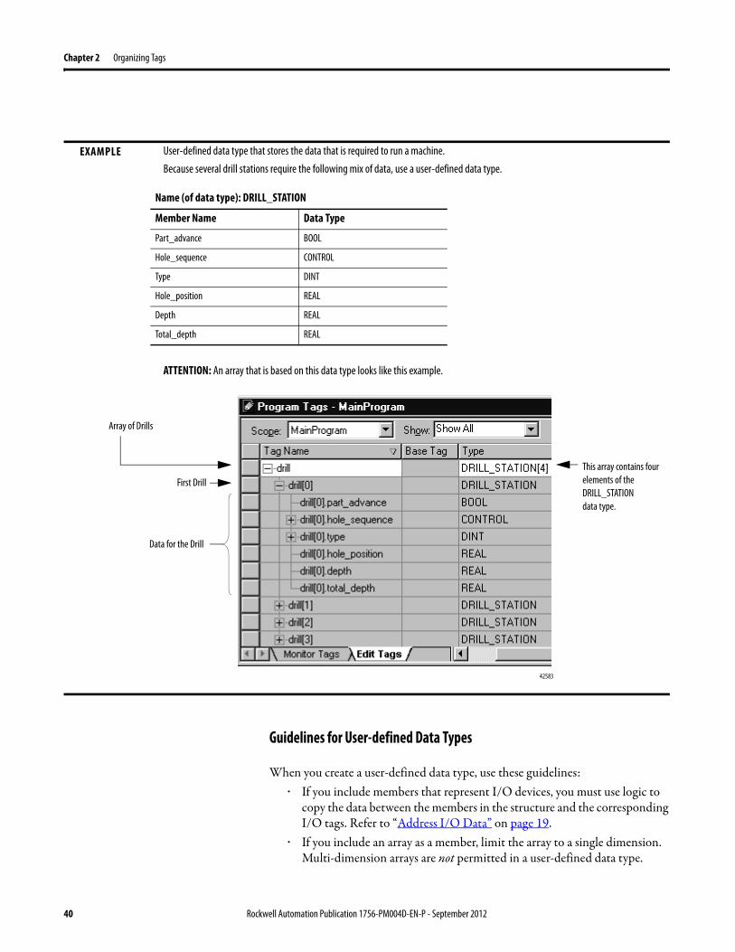
Guidelines for User-defined Data Types
When you create a user-defined data type, use these guidelines:· If you include members that represent I/O devices, you must use logic to
copy the data between the members in the structure and the corresponding I/O tags. Refer to “Address I/O Data” on page 19.
· If you include an array as a member, limit the array to a single dimension. Multi-dimension arrays are not permitted in a user-defined data type.
EXAMPLE User-defined data type that stores the data that is required to run a machine.
Because several drill stations require the following mix of data, use a user-defined data type.
ATTENTION: An array that is based on this data type looks like this example.
Name (of data type): DRILL_STATION
Member Name Data Type
Part_advance BOOL
Hole_sequence CONTROL
Type DINT
Hole_position REAL
Depth REAL
Total_depth REAL
42583
Array of Drills
First DrillThis array contains four elements of the DRILL_STATION
data type.
Data for the Drill
40 Rockwell Automation Publication 1756-PM004D-EN-P - September 2012
Organizing Tags Chapter 2
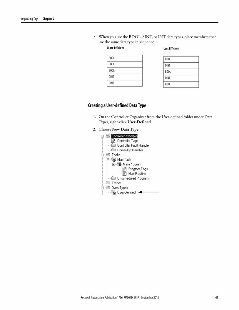
· When you use the BOOL, SINT, or INT data types, place members that use the same data type in sequence.
Creating a User-defined Data Type
1. On the Controller Organizer from the User-defined folder under Data Types, right-click User-Defined.
2. Choose New Data Type.
More Efficient
BOOL
BOOL
BOOL
DINT
DINT
Less Efficient
BOOL
DINT
BOOL
DINT
BOOL
Rockwell Automation Publication 1756-PM004D-EN-P - September 2012 41
Chapter 2 Organizing Tags
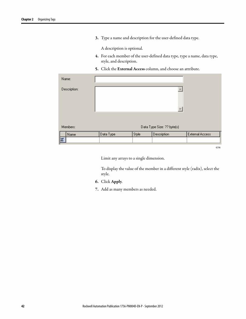
3. Type a name and description for the user-defined data type.
A description is optional.
4. For each member of the user-defined data type, type a name, data type, style, and description.
5. Click the External Access column, and choose an attribute.
Limit any arrays to a single dimension.
To display the value of the member in a different style (radix), select the style.
6. Click Apply.
7. Add as many members as needed.
42196
42 Rockwell Automation Publication 1756-PM004D-EN-P - September 2012
Organizing Tags Chapter 2
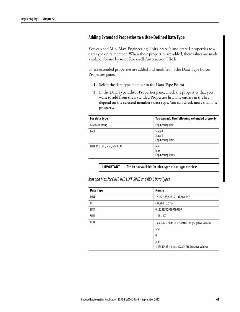
Adding Extended Properties to a User-Defined Data Type
You can add Min, Max, Engineering Units, State 0, and State 1 properties to a data type or its member. When these properties are added, their values are made available for use by some Rockwell Automation HMIs.
These extended properties are added and modified in the Data Type Editor Properties pane.
1. Select the data type member in the Data Type Editor
2. In the Data Type Editor Properties pane, check the properties that you want to add from the Extended Properties list. The entries in the list depend on the selected member’s data type. You can check more than one property.
Min and Max for DINT, INT, LINT, SINT, and REAL Data Types
For data type You can add the following extended property
Array and string Engineering Unit
Bool State 0State 1Engineering Unit
DINT, INT, LINT, SINT, and REAL MinMaxEngineering Units
IMPORTANT The list is unavailable for other types of data type members.
Data Type Range
DINT -2,147,483,648...2,147,483,647
INT -32,768...32,767
LINT 0...32535129599999999
SINT -128...127
REAL -3.402823E38 to -1.1754944E-38 (negative values)
and
0
and1.1754944E-38 to 3.402823E38 (positive values)
Rockwell Automation Publication 1756-PM004D-EN-P - September 2012 43
Chapter 2 Organizing Tags
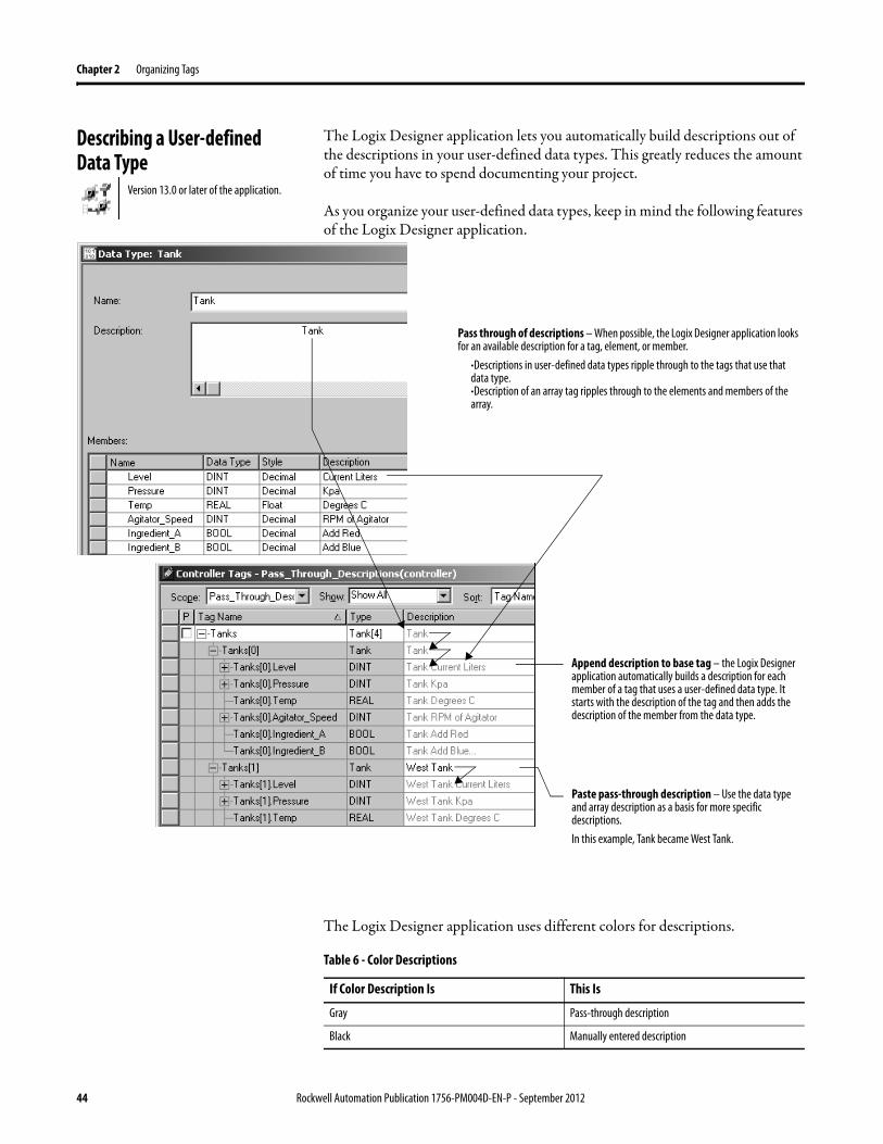
Describing a User-defined Data Type
The Logix Designer application lets you automatically build descriptions out of the descriptions in your user-defined data types. This greatly reduces the amount of time you have to spend documenting your project.
As you organize your user-defined data types, keep in mind the following features of the Logix Designer application.
The Logix Designer application uses different colors for descriptions.
Version 13.0 or later of the application.
Pass through of descriptions – When possible, the Logix Designer application looks for an available description for a tag, element, or member.
·Descriptions in user-defined data types ripple through to the tags that use that data type.·Description of an array tag ripples through to the elements and members of the array.
Paste pass-through description – Use the data type and array description as a basis for more specific descriptions. In this example, Tank became West Tank.
Append description to base tag – the Logix Designer application automatically builds a description for each member of a tag that uses a user-defined data type. It starts with the description of the tag and then adds the description of the member from the data type.
Table 6 - Color Descriptions
If Color Description Is This Is
Gray Pass-through description
Black Manually entered description
44 Rockwell Automation Publication 1756-PM004D-EN-P - September 2012
Organizing Tags Chapter 2
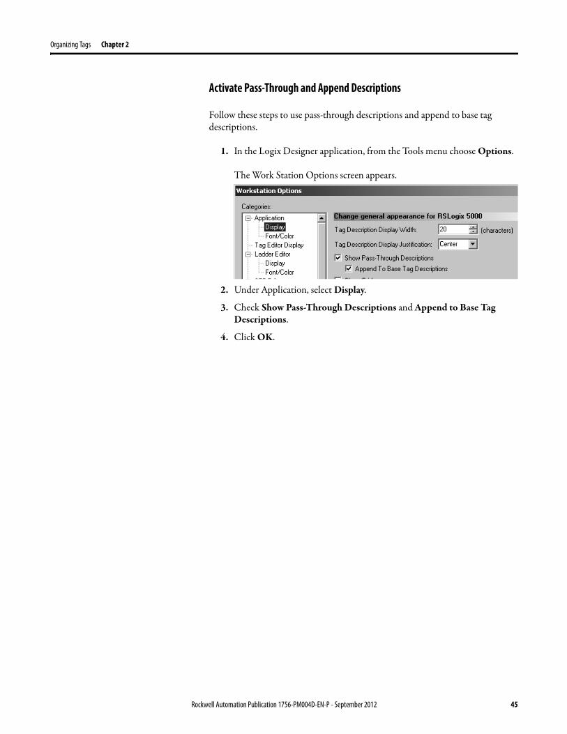
Activate Pass-Through and Append Descriptions
Follow these steps to use pass-through descriptions and append to base tag descriptions.
1. In the Logix Designer application, from the Tools menu choose Options.
The Work Station Options screen appears.
2. Under Application, select Display.
3. Check Show Pass-Through Descriptions and Append to Base Tag Descriptions.
4. Click OK.
Rockwell Automation Publication 1756-PM004D-EN-P - September 2012 45
Chapter 2 Organizing Tags
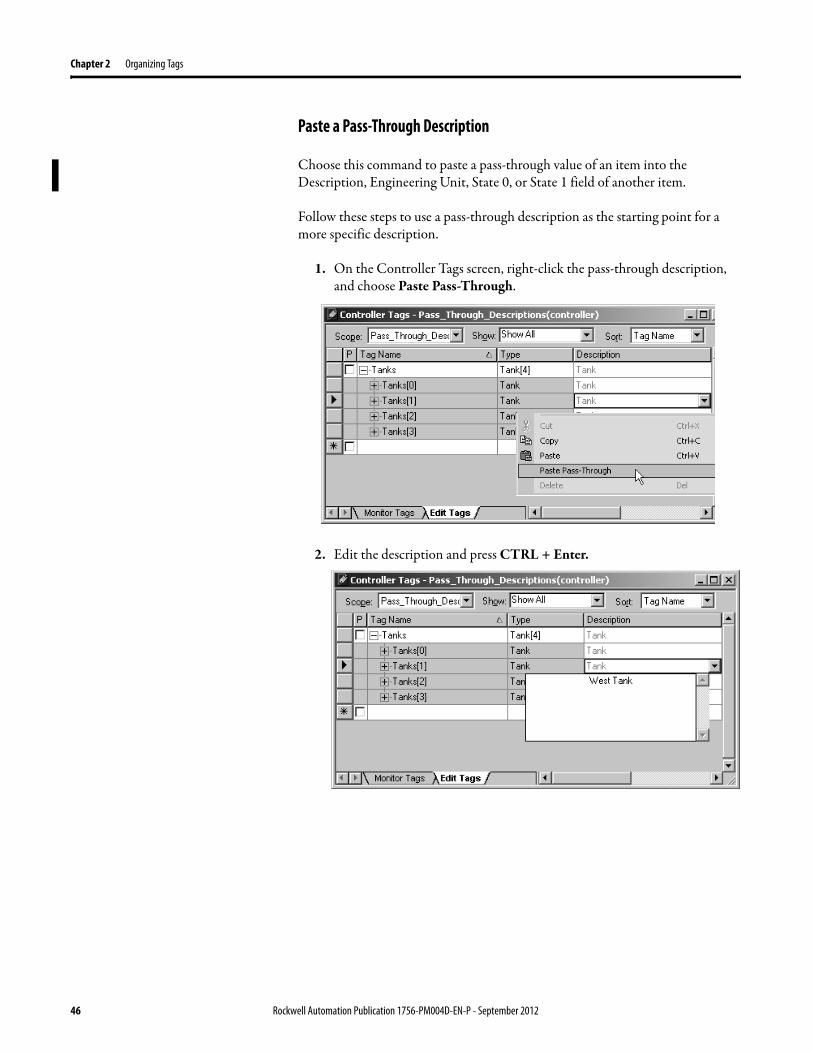
Paste a Pass-Through Description
Choose this command to paste a pass-through value of an item into the Description, Engineering Unit, State 0, or State 1 field of another item.
Follow these steps to use a pass-through description as the starting point for a more specific description.
1. On the Controller Tags screen, right-click the pass-through description, and choose Paste Pass-Through.
2. Edit the description and press CTRL + Enter.
46 Rockwell Automation Publication 1756-PM004D-EN-P - September 2012
Organizing Tags Chapter 2
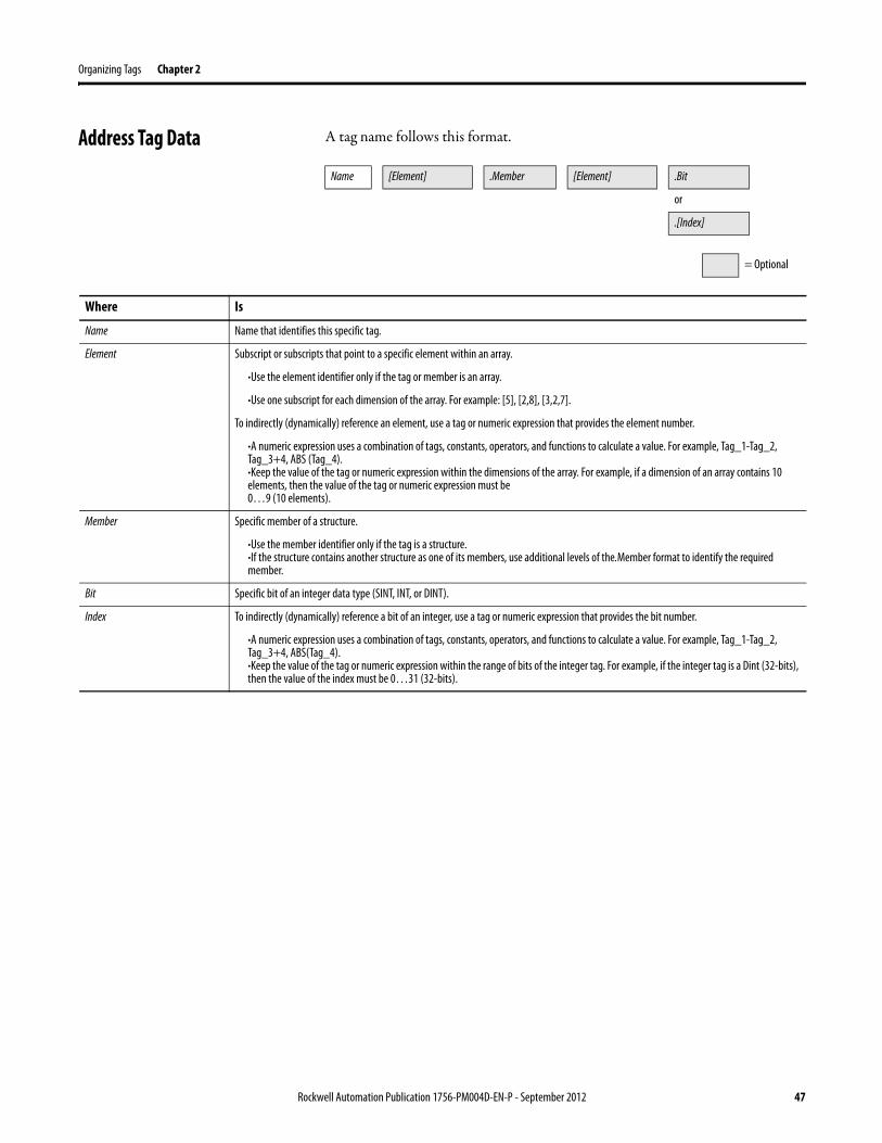
Address Tag Data A tag name follows this format.
Name [Element] .Member [Element] .Bit
or
.[Index]
= Optional
Where Is
Name Name that identifies this specific tag.
Element Subscript or subscripts that point to a specific element within an array.
·Use the element identifier only if the tag or member is an array.
·Use one subscript for each dimension of the array. For example: [5], [2,8], [3,2,7].
To indirectly (dynamically) reference an element, use a tag or numeric expression that provides the element number.
·A numeric expression uses a combination of tags, constants, operators, and functions to calculate a value. For example, Tag_1-Tag_2, Tag_3+4, ABS (Tag_4).·Keep the value of the tag or numeric expression within the dimensions of the array. For example, if a dimension of an array contains 10 elements, then the value of the tag or numeric expression must be
0…9 (10 elements).
Member Specific member of a structure.
·Use the member identifier only if the tag is a structure.·If the structure contains another structure as one of its members, use additional levels of the.Member format to identify the required member.
Bit Specific bit of an integer data type (SINT, INT, or DINT).
Index To indirectly (dynamically) reference a bit of an integer, use a tag or numeric expression that provides the bit number.
·A numeric expression uses a combination of tags, constants, operators, and functions to calculate a value. For example, Tag_1-Tag_2, Tag_3+4, ABS(Tag_4).·Keep the value of the tag or numeric expression within the range of bits of the integer tag. For example, if the integer tag is a Dint (32-bits), then the value of the index must be 0…31 (32-bits).
Rockwell Automation Publication 1756-PM004D-EN-P - September 2012 47
Chapter 2 Organizing Tags
Alias Tags An alias tag lets you create one tag that represents another tag.· Both tags share the same value.· When the value of one of the tags changes, the other tag reflects the change
as well.
Use aliases in the following situations:· Program logic in advance of wiring diagrams.· Assign a descriptive name to an I/O device.· Provide a more simple name for a complex tag.· Use a descriptive name for an element of an array.
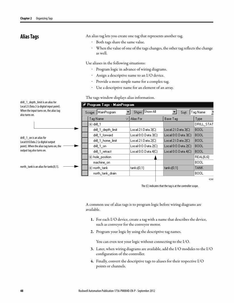
The tags window displays alias information.
A common use of alias tags is to program logic before wiring diagrams are available.
1. For each I/O device, create a tag with a name that describes the device, such as conveyor for the conveyor motor.
2. Program your logic by using the descriptive tag names.
You can even test your logic without connecting to the I/O.
3. Later, when wiring diagrams are available, add the I/O modules to the I/O configuration of the controller.
4. Finally, convert the descriptive tags to aliases for their respective I/O points or channels.
drill_1_depth_limit is an alias for Local:2:I.Data.3 (a digital input point). When the input turns on, the alias tag also turns on.
drill_1_on is an alias for Local:0:O.Data.2 (a digital output point). When the alias tag turns on, the output tag also turns on.
north_tank is an alias for tanks[0,1].
42360
The (C) indicates that the tag is at the controller scope.
48 Rockwell Automation Publication 1756-PM004D-EN-P - September 2012
Organizing Tags Chapter 2
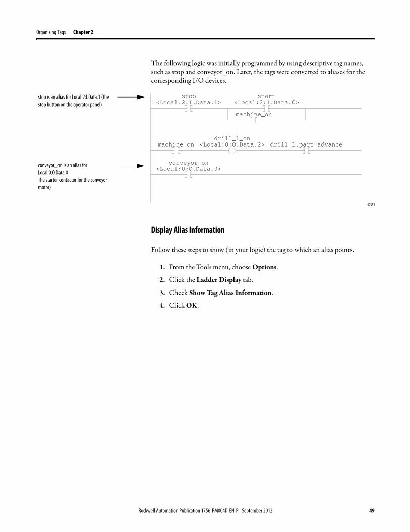
The following logic was initially programmed by using descriptive tag names, such as stop and conveyor_on. Later, the tags were converted to aliases for the corresponding I/O devices.
42351
Display Alias Information
Follow these steps to show (in your logic) the tag to which an alias points.
1. From the Tools menu, choose Options.
2. Click the Ladder Display tab.
3. Check Show Tag Alias Information.
4. Click OK.
stop<Local:2:I.Data.1>
start<Local:2:I.Data.0>
machine_on
machine_ondrill_1_on
<Local:0:O.Data.2> drill_1.part_advance
conveyor_on<Local:0:O.Data.0>
stop is an alias for Local:2:I.Data.1 (the stop button on the operator panel)
conveyor_on is an alias for Local:0:O.Data.0 The starter contactor for the conveyor motor)
Rockwell Automation Publication 1756-PM004D-EN-P - September 2012 49
Chapter 2 Organizing Tags
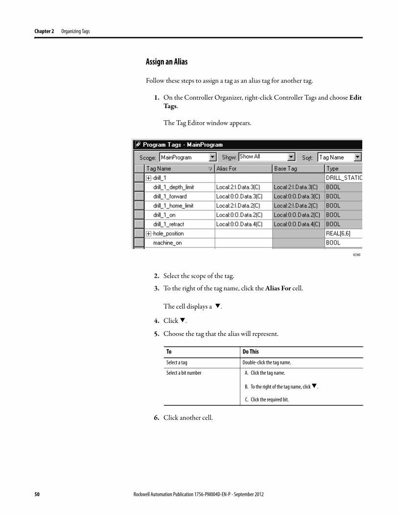
Assign an Alias
Follow these steps to assign a tag as an alias tag for another tag.
1. On the Controller Organizer, right-click Controller Tags and choose Edit Tags.
The Tag Editor window appears.
2. Select the scope of the tag.
3. To the right of the tag name, click the Alias For cell.
The cell displays a >.
4. Click >.
5. Choose the tag that the alias will represent.
6. Click another cell.
42360
To Do This
Select a tag Double-click the tag name.
Select a bit number A. Click the tag name.
B. To the right of the tag name, click >.
C. Click the required bit.
50 Rockwell Automation Publication 1756-PM004D-EN-P - September 2012
Organizing Tags Chapter 2
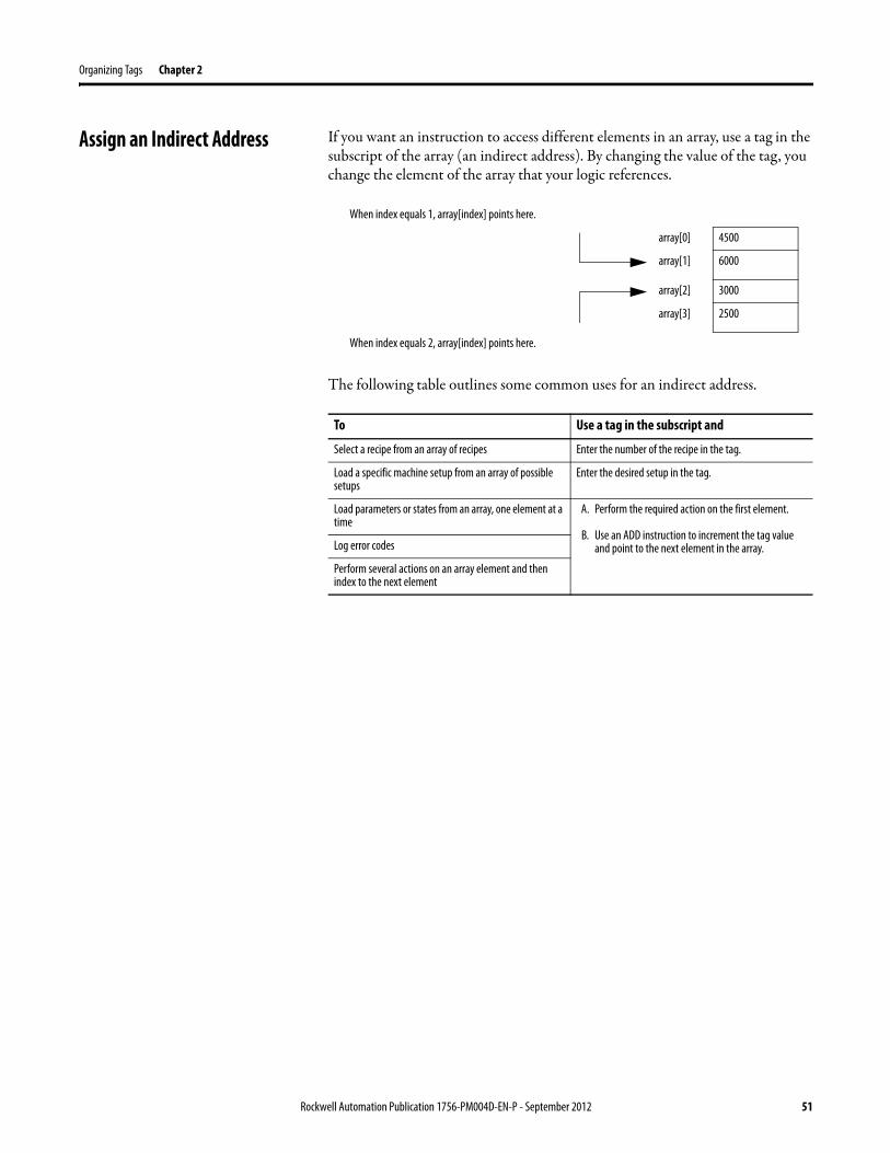
Assign an Indirect Address If you want an instruction to access different elements in an array, use a tag in the subscript of the array (an indirect address). By changing the value of the tag, you change the element of the array that your logic references.
The following table outlines some common uses for an indirect address.
When index equals 1, array[index] points here.
array[0] 4500
array[1] 6000
array[2] 3000
array[3] 2500
When index equals 2, array[index] points here.
To Use a tag in the subscript and
Select a recipe from an array of recipes Enter the number of the recipe in the tag.
Load a specific machine setup from an array of possible setups
Enter the desired setup in the tag.
Load parameters or states from an array, one element at a time
A. Perform the required action on the first element.
B. Use an ADD instruction to increment the tag value and point to the next element in the array.Log error codes
Perform several actions on an array element and then index to the next element
Rockwell Automation Publication 1756-PM004D-EN-P - September 2012 51
Chapter 2 Organizing Tags
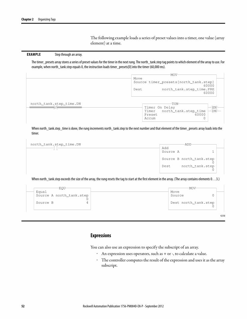
The following example loads a series of preset values into a timer, one value (array element) at a time.
Expressions
You can also use an expression to specify the subscript of an array.· An expression uses operators, such as + or -, to calculate a value.· The controller computes the result of the expression and uses it as the array
subscript.
EXAMPLE Step through an array.
The timer_presets array stores a series of preset values for the timer in the next rung. The north_tank.step tag points to which element of the array to use. For example, when north_tank.step equals 0, the instruction loads timer_presets[0] into the timer (60,000 ms).
When north_tank.step_time is done, the rung increments north_tank.step to the next number and that element of the timer_presets array loads into the timer.
When north_tank.step exceeds the size of the array, the rung resets the tag to start at the first element in the array. (The array contains elements 0…3.)
42358
MoveSource timer_presets[north_tank.step]
60000Dest north_tank.step_time.PRE
60000
MOV
/north_tank.step_time.DN
ENDN
Timer On DelayTimer north_tank.step_timePreset 60000Accum 0
TON
north_tank.step_time.DNAddSource A 1
Source B north_tank.step0
Dest north_tank.step0
ADD
EqualSource A north_tank.step
0Source B 4
EQUMoveSource 0
Dest north_tank.step0
MOV
52 Rockwell Automation Publication 1756-PM004D-EN-P - September 2012
Organizing Tags Chapter 2
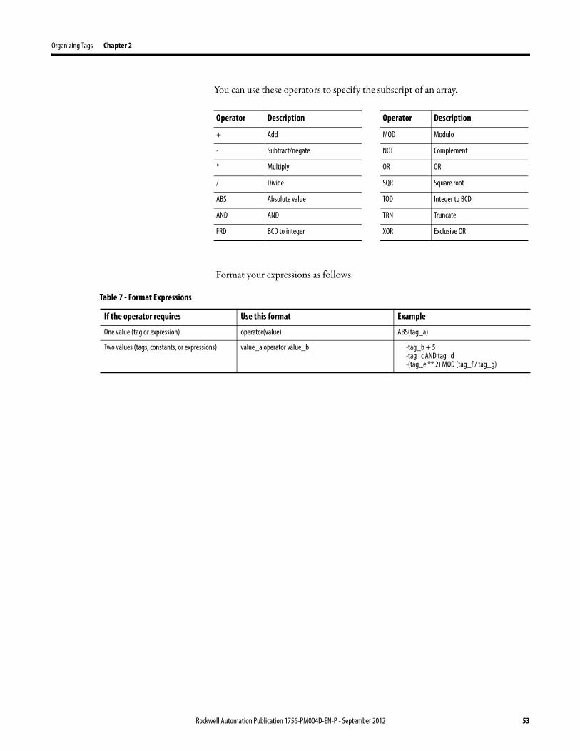
You can use these operators to specify the subscript of an array.
Format your expressions as follows.
Operator Description
+ Add
- Subtract/negate
* Multiply
/ Divide
ABS Absolute value
AND AND
FRD BCD to integer
MOD Modulo
NOT Complement
OR OR
SQR Square root
TOD Integer to BCD
TRN Truncate
XOR Exclusive OR
Operator Description
Table 7 - Format Expressions
If the operator requires Use this format Example
One value (tag or expression) operator(value) ABS(tag_a)
Two values (tags, constants, or expressions) value_a operator value_b ·tag_b + 5·tag_c AND tag_d·(tag_e ** 2) MOD (tag_f / tag_g)
Rock
well Automation Publication 1756-PM004D-EN-P - September 2012 53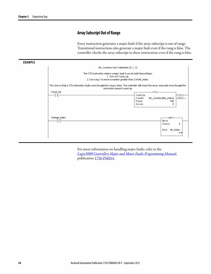
Chapter 2 Organizing Tags
Array Subscript Out of Range
Every instruction generates a major fault if the array subscript is out of range. Transitional instructions also generate a major fault even if the rung is false. The controller checks the array subscript in these instructions even if the rung is false.
For more information on handling major faults, refer to the
Logix5000 Controllers Major and Minor Faults Programming Manual, publication 1756-PM014.
EXAMPLEe
54 Rockwell Automation Publication 1756-PM004D-EN-P - September 2012
Organizing Tags Chapter 2
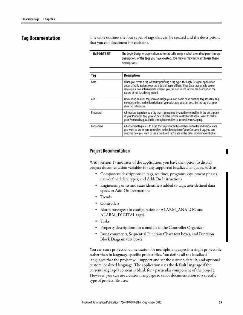
Tag Documentation The table outlines the four types of tags that can be created and the descriptions that you can document for each one.
Project Documentation
With version 17 and later of the application, you have the option to display project documentation variables for any supported localized language, such as:
• Component descriptions in tags, routines, programs, equipment phases, user-defined data types, and Add-On Instructions
• Engineering units and state identifiers added to tags, user-defined data types, or Add-On Instructions
• Trends• Controllers• Alarm messages (in configuration of ALARM_ANALOG and
ALARM_DIGITAL tags)• Tasks• Property descriptions for a module in the Controller Organizer• Rung comments, Sequential Function Chart text boxes, and Function
Block Diagram text boxes
You can store project documentation for multiple languages in a single project file rather than in language-specific project files. You define all the localized languages that the project will support and set the current, default, and optional custom localized language. The application uses the default language if the current language's content is blank for a particular component of the project. However, you can use a custom language to tailor documentation to a specific type of project file user.
IMPORTANT The Logix Designer application automatically assigns what are called pass-through descriptions of the tags you have created. You may or may not want to use these descriptions.
Tag Description
Base When you create a tag without specifying a tag type, the Logix Designer application automatically assigns your tag a default type of Base. Since base tags enable you to create your own internal data storage, you can document in your tag description the nature of the data being stored.
Alias By creating an Alias tag, you can assign your own name to an existing tag, structure tag member, or bit. In the description of your Alias tag, you can describe the tag that your alias tag references.
Produced A Produced tag refers to a tag that is consumed by another controller. In the description of your Produced tag, you can describe the remote controllers that you want to make your Produced tag available through controller-to-controller messaging.
Consumed A Consumed tag refers to a tag that is produced by another controller and whose data you want to use in your controller. In the description of your Consumed tag, you can describe how you want to use a produced tag’s data or the data-producing controller.
Rockwell Automation Publication 1756-PM004D-EN-P - September 2012 55
Chapter 2 Organizing Tags
Enter the localized descriptions in your Logix Designer project, either when programming in that language or by using the import/export utility to translate the documentation off-line and then import it back into the project. Once you enable documentation languages in the Logix Designer application, you can dynamically switch between languages as you use the application.
For more information on enabling a project to support multiple translations of project documentation, see the online help.
56 Rockwell Automation Publication 1756-PM004D-EN-P - September 2012
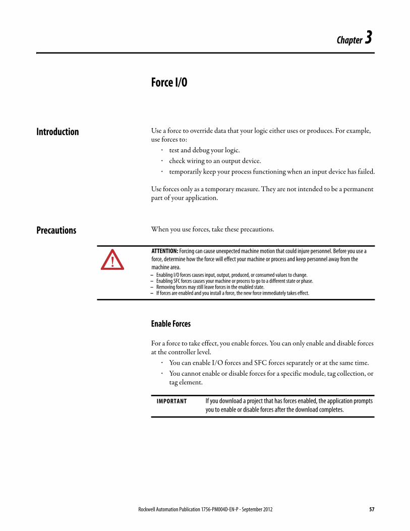
Chapter 3
Force I/O
Introduction Use a force to override data that your logic either uses or produces. For example, use forces to:
· test and debug your logic.· check wiring to an output device.· temporarily keep your process functioning when an input device has failed.
Use forces only as a temporary measure. They are not intended to be a permanent part of your application.
Precautions When you use forces, take these precautions.
Enable Forces
For a force to take effect, you enable forces. You can only enable and disable forces at the controller level.
· You can enable I/O forces and SFC forces separately or at the same time.· You cannot enable or disable forces for a specific module, tag collection, or
tag element.
ATTENTION: Forcing can cause unexpected machine motion that could injure personnel. Before you use a force, determine how the force will effect your machine or process and keep personnel away from the machine area.
– Enabling I/O forces causes input, output, produced, or consumed values to change.– Enabling SFC forces causes your machine or process to go to a different state or phase.– Removing forces may still leave forces in the enabled state.– If forces are enabled and you install a force, the new force immediately takes effect.
IMPORTANT If you download a project that has forces enabled, the application prompts you to enable or disable forces after the download completes.
Rockwell Automation Publication 1756-PM004D-EN-P - September 2012 57
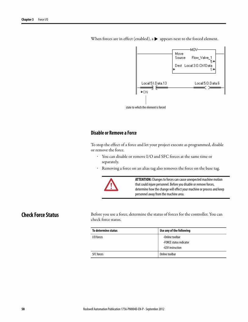
Chapter 3 Force I/O
When forces are in effect (enabled), a appears next to the forced element.
Disable or Remove a Force
To stop the effect of a force and let your project execute as programmed, disable or remove the force.
· You can disable or remove I/O and SFC forces at the same time or separately.
· Removing a force on an alias tag also removes the force on the base tag.
Check Force Status Before you use a force, determine the status of forces for the controller. You can check force status.
ATTENTION: Changes to forces can cause unexpected machine motion that could injure personnel. Before you disable or remove forces, determine how the change will effect your machine or process and keep personnel away from the machine area.
▼
state to which the element is forced
To determine status Use any of the following
I/O forces ·Online toolbar·FORCE status indicator·GSV instruction
SFC forces Online toolbar
58 Rockwell Automation Publication 1756-PM004D-EN-P - September 2012
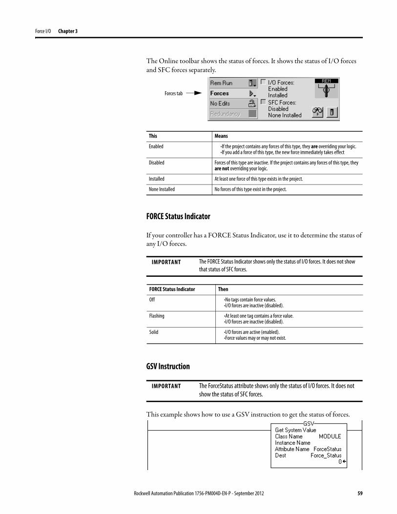
Force I/O Chapter 3
The Online toolbar shows the status of forces. It shows the status of I/O forces and SFC forces separately.
FORCE Status Indicator
If your controller has a FORCE Status Indicator, use it to determine the status of any I/O forces.
GSV Instruction
This example shows how to use a GSV instruction to get the status of forces.
Forces tab
This Means
Enabled ·If the project contains any forces of this type, they are overriding your logic. ·If you add a force of this type, the new force immediately takes effect
Disabled Forces of this type are inactive. If the project contains any forces of this type, they are not overriding your logic.
Installed At least one force of this type exists in the project.
None Installed No forces of this type exist in the project.
IMPORTANT The FORCE Status Indicator shows only the status of I/O forces. It does not show that status of SFC forces.
FORCE Status Indicator Then
Off ·No tags contain force values.·I/O forces are inactive (disabled).
Flashing ·At least one tag contains a force value.·I/O forces are inactive (disabled).
Solid ·I/O forces are active (enabled).·Force values may or may not exist.
IMPORTANT The ForceStatus attribute shows only the status of I/O forces. It does not show the status of SFC forces.
Rockwell Automation Publication 1756-PM004D-EN-P - September 2012 59
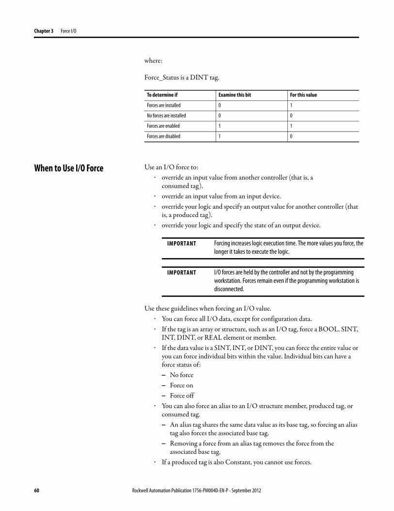
Chapter 3 Force I/O
where:
Force_Status is a DINT tag.
When to Use I/O Force Use an I/O force to:· override an input value from another controller (that is, a
consumed tag).· override an input value from an input device.· override your logic and specify an output value for another controller (that
is, a produced tag).· override your logic and specify the state of an output device.
Use these guidelines when forcing an I/O value.· You can force all I/O data, except for configuration data.· If the tag is an array or structure, such as an I/O tag, force a BOOL, SINT,
INT, DINT, or REAL element or member.· If the data value is a SINT, INT, or DINT, you can force the entire value or
you can force individual bits within the value. Individual bits can have a force status of:– No force– Force on– Force off
· You can also force an alias to an I/O structure member, produced tag, or consumed tag.– An alias tag shares the same data value as its base tag, so forcing an alias
tag also forces the associated base tag.– Removing a force from an alias tag removes the force from the
associated base tag.· If a produced tag is also Constant, you cannot use forces.
To determine if Examine this bit For this value
Forces are installed 0 1
No forces are installed 0 0
Forces are enabled 1 1
Forces are disabled 1 0
IMPORTANT Forcing increases logic execution time. The more values you force, the longer it takes to execute the logic.
IMPORTANT I/O forces are held by the controller and not by the programming workstation. Forces remain even if the programming workstation is disconnected.
60 Rockwell Automation Publication 1756-PM004D-EN-P - September 2012
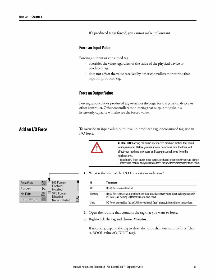
Force I/O Chapter 3
· If a produced tag is forced, you cannot make it Constant.
Force an Input Value
Forcing an input or consumed tag:· overrides the value regardless of the value of the physical device or
produced tag.· does not affect the value received by other controllers monitoring that
input or produced tag.
Force an Output Value
Forcing an output or produced tag overrides the logic for the physical device or other controller. Other controllers monitoring that output module in a listen-only capacity will also see the forced value.
Add an I/O Force To override an input value, output value, produced tag, or consumed tag, use an I/O force.
1. What is the state of the I/O Forces status indicator?
2. Open the routine that contains the tag that you want to force.
3. Right-click the tag and choose Monitor.
If necessary, expand the tag to show the value that you want to force (that is, BOOL value of a DINT tag).
ATTENTION: Forcing can cause unexpected machine motion that could injure personnel. Before you use a force, determine how the force will effect your machine or process and keep personnel away from the machine area.
– Enabling I/O forces causes input, output, produced, or consumed values to change. – If forces are enabled and you install a force, the new force immediately takes effect.
If Then note
Off No I/O forces currently exist.
Flashing No I/O forces are active. But at least one force already exists in your project. When you enable I/O forces, all existing I/O forces will also take effect.
Solid I/O forces are enabled (active). When you install (add) a force, it immediately takes effect.
Rockwell Automation Publication 1756-PM004D-EN-P - September 2012 61
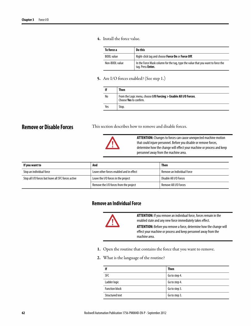
Chapter 3 Force I/O
4. Install the force value.
5. Are I/O forces enabled? (See step 1.)
Remove or Disable Forces This section describes how to remove and disable forces.
Remove an Individual Force
1. Open the routine that contains the force that you want to remove.
2. What is the language of the routine?
To force a Do this
BOOL value Right-click tag and choose Force On or Force Off.
Non-BOOL value In the Force Mask column for the tag, type the value that you want to force the tag. Press Enter.
If Then
No From the Logic menu, choose I/O Forcing > Enable All I/O Forces. Choose Yes to confirm.
Yes Stop.
ATTENTION: Changes to forces can cause unexpected machine motion that could injure personnel. Before you disable or remove forces, determine how the change will effect your machine or process and keep personnel away from the machine area.
If you want to And Then
Stop an individual force Leave other forces enabled and in effect Remove an Individual Force
Stop all I/O forces but leave all SFC forces active Leave the I/O forces in the project Disable All I/O Forces
Remove the I/O forces from the project Remove All I/O Forces
ATTENTION: If you remove an individual force, forces remain in the enabled state and any new force immediately takes effect.
ATTENTION: Before you remove a force, determine how the change will effect your machine or process and keep personnel away from the machine area.
If Then
SFC Go to step 4.
Ladder logic Go to step 4.
Function block Go to step 3.
Structured text Go to step 3.
62 Rockwell Automation Publication 1756-PM004D-EN-P - September 2012
Force I/O Chapter 3
3. Right-click a tag that has the force and choose Monitor.
If necessary, expand the tag to show the value that is forced, for example, BOOL value of a DINT tag.
4. Right-click a tag or element that has the force and choose Remove Force.
Disable All I/O Forces
To disable, choose Logic>I/O Forcing>Disable All I/O Forces. Click Yes to confirm.
Remove All I/O Forces
To remove, choose Logic>I/O Forcing>Remove All I/O Forces. Click Yes to confirm.
Rockwell Automation Publication 1756-PM004D-EN-P - September 2012 63

Chapter 3 Force I/O
Notes:
64 Rockwell Automation Publication 1756-PM004D-EN-P - September 2012
Chapter 4
Data Access Control
Introduction In the Logix platform, version 18 or later of the application, there are two tag attributes that allow you to control access to tag data. These attributes are:
• External Access• Constant
The External Access attribute controls how external applications, such as HMIs, can access tags. It has possible values of Read/Write, Read Only, and None. See “Configure External Access” on page 66.
The Constant attribute value determines if a tag can be modified by controller logic. Also, by using FactoryTalk Security software, it is possible to control which users are permitted to change tags designated as constants in the Logix Designer application. See page 77 for more information on the Constant attribute.
By using these two attributes, you can help safeguard tag data by preventing unwanted changes to tag values. Also, by reducing the number of tags exposed to external applications, you can also reduce the time required to develop
HMI screens.
External Access By using the External Access attribute, you can control how external applications and devices can access tags.
This process can help you manage the thousands of tags you might have in a project that have similar names that can get easily confused when referencing them in applications or devices.
Using this attribute also can help improve system performance by reducing the number of tags RSLinx has to maintain, scan, and cache. This volume can impact the performance of the RSLinx data server and other related applications.
External applications and devices include:• RSLinx Classic and RSLinx Enterprise software.• other Logix controllers.• PanelView terminals.• PLC/SLC controllers.• FactoryTalk Historian software.• other third-party software.
Rockwell Automation Publication 1756-PM004D-EN-P - September 2012 65
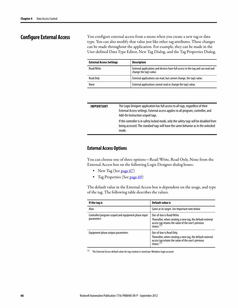
Chapter 4 Data Access Control
Configure External Access You configure external access from a menu when you create a new tag or data type. You can also modify that value just like other tag attributes. These changes can be made throughout the application. For example, they can be made in the User-defined Data Type Editor, New Tag Dialog, and the Tag Properties Dialog.
External Access Options
You can choose one of three options—Read/Write, Read Only, None from the External Access box on the following Logix Designer dialog boxes:
• New Tag (See page 67)• Tag Properties (See page 69)
The default value in the External Access box is dependent on the usage, and type of the tag. The following table describes the values.
External Access Settings Description
Read/Write External applications and devices have full access to the tag and can read and change the tag’s value.
Read Only External applications can read, but cannot change, the tag’s value.
None External applications cannot read or change the tag’s value.
IMPORTANT The Logix Designer application has full access to all tags, regardless of their External Access settings. External access applies to all program, controller, and Add-On Instruction scoped tags.
If the controller is in safety locked mode, only the safety tags will be disabled from being accessed. The standard tags will have the same behavior as in the unlocked mode.
If the tag is Default value is
Alias Same as its target. See Important note below.
Controller/program scoped and equipment phase input parameters
Out-of-box is Read/Write.Thereafter, when creating a new tag, the default external access tag retains the value of the user’s previous choice.(1)
(1) The External Access default value for tag creation is stored per Windows login account.
Equipment phase output parameters Out-of-box is Read Only. Thereafter, when creating a new tag, the default external access tag retains the value of the user’s previous choice.(1)
66 Rockwell Automation Publication 1756-PM004D-EN-P - September 2012
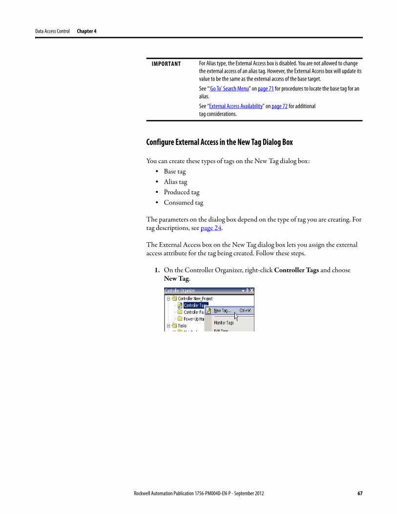
Data Access Control Chapter 4
Configure External Access in the New Tag Dialog Box
You can create these types of tags on the New Tag dialog box:• Base tag• Alias tag• Produced tag• Consumed tag
The parameters on the dialog box depend on the type of tag you are creating. For tag descriptions, see page 24.
The External Access box on the New Tag dialog box lets you assign the external access attribute for the tag being created. Follow these steps.
1. On the Controller Organizer, right-click Controller Tags and choose New Tag.
IMPORTANT For Alias type, the External Access box is disabled. You are not allowed to change the external access of an alias tag. However, the External Access box will update its value to be the same as the external access of the base target.
See “‘Go To’ Search Menu” on page 71 for procedures to locate the base tag for an alias.
See “External Access Availability” on page 72 for additional tag considerations.
Rockwell Automation Publication 1756-PM004D-EN-P - September 2012 67
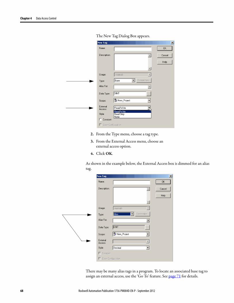
Chapter 4 Data Access Control
The New Tag Dialog Box appears.
2. From the Type menu, choose a tag type.
3. From the External Access menu, choose an
external access option.
4. Click OK.
As shown in the example below, the External Access box is dimmed for an alias tag.
There may be many alias tags in a program. To locate an associated base tag to assign an external access, use the ‘Go To’ feature. See page 71 for details.
68 Rockwell Automation Publication 1756-PM004D-EN-P - September 2012
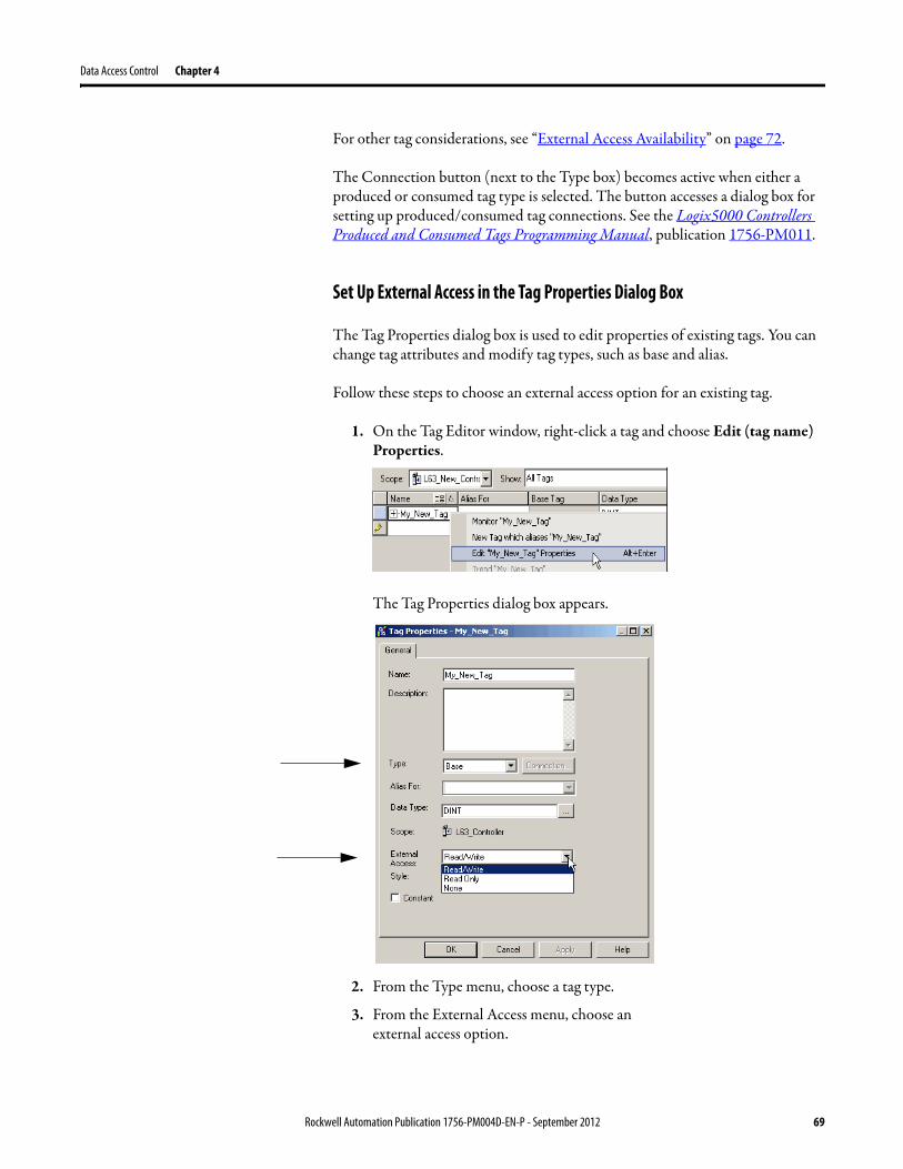
Data Access Control Chapter 4
For other tag considerations, see “External Access Availability” on page 72.
The Connection button (next to the Type box) becomes active when either a produced or consumed tag type is selected. The button accesses a dialog box for setting up produced/consumed tag connections. See the Logix5000 Controllers Produced and Consumed Tags Programming Manual, publication 1756-PM011.
Set Up External Access in the Tag Properties Dialog Box
The Tag Properties dialog box is used to edit properties of existing tags. You can change tag attributes and modify tag types, such as base and alias.
Follow these steps to choose an external access option for an existing tag.
1. On the Tag Editor window, right-click a tag and choose Edit (tag name) Properties.
The Tag Properties dialog box appears.
2. From the Type menu, choose a tag type.
3. From the External Access menu, choose an
external access option.
Rockwell Automation Publication 1756-PM004D-EN-P - September 2012 69
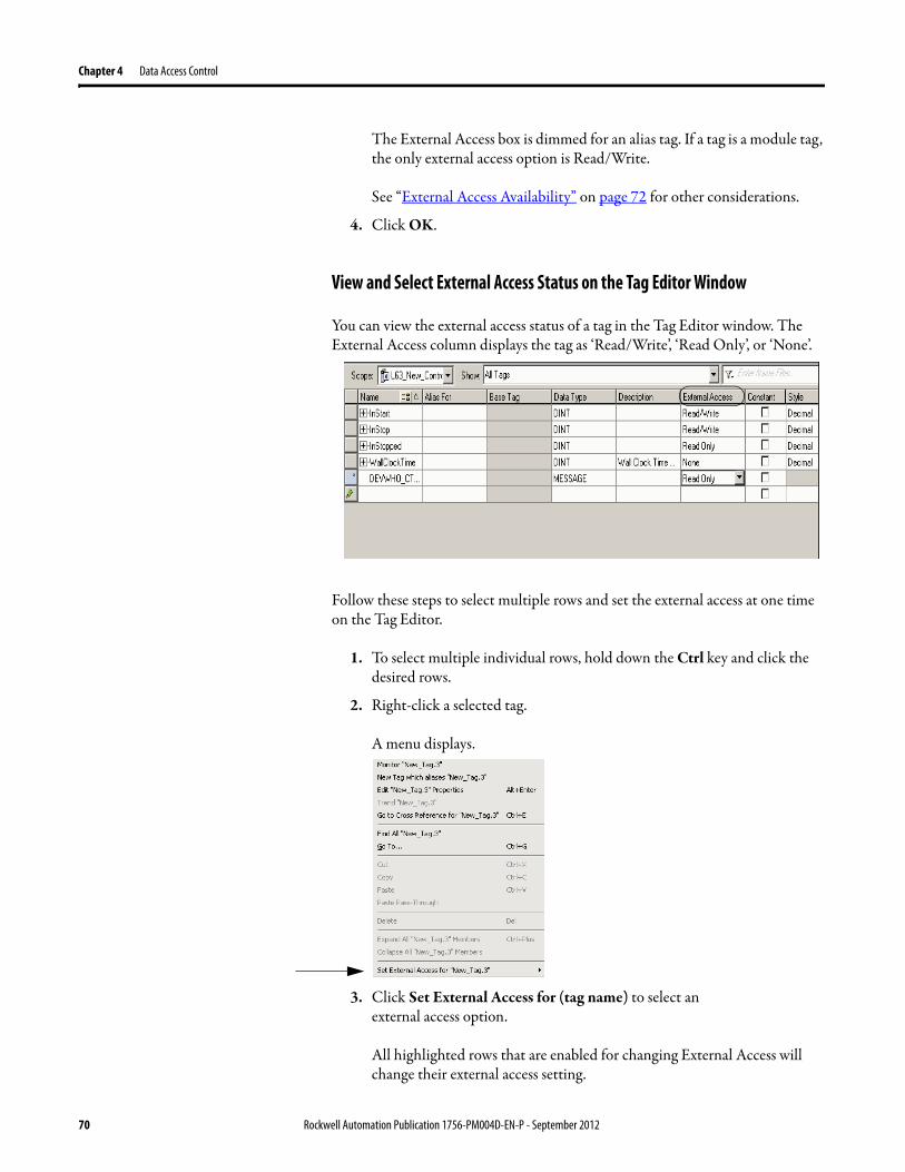
Chapter 4 Data Access Control
The External Access box is dimmed for an alias tag. If a tag is a module tag, the only external access option is Read/Write.
See “External Access Availability” on page 72 for other considerations.
4. Click OK.
View and Select External Access Status on the Tag Editor Window
You can view the external access status of a tag in the Tag Editor window. The External Access column displays the tag as ‘Read/Write’, ‘Read Only’, or ‘None’.
Follow these steps to select multiple rows and set the external access at one time on the Tag Editor.
1. To select multiple individual rows, hold down the Ctrl key and click the desired rows.
2. Right-click a selected tag.
A menu displays.
3. Click Set External Access for (tag name) to select an
external access option.
All highlighted rows that are enabled for changing External Access will change their external access setting.
70 Rockwell Automation Publication 1756-PM004D-EN-P - September 2012
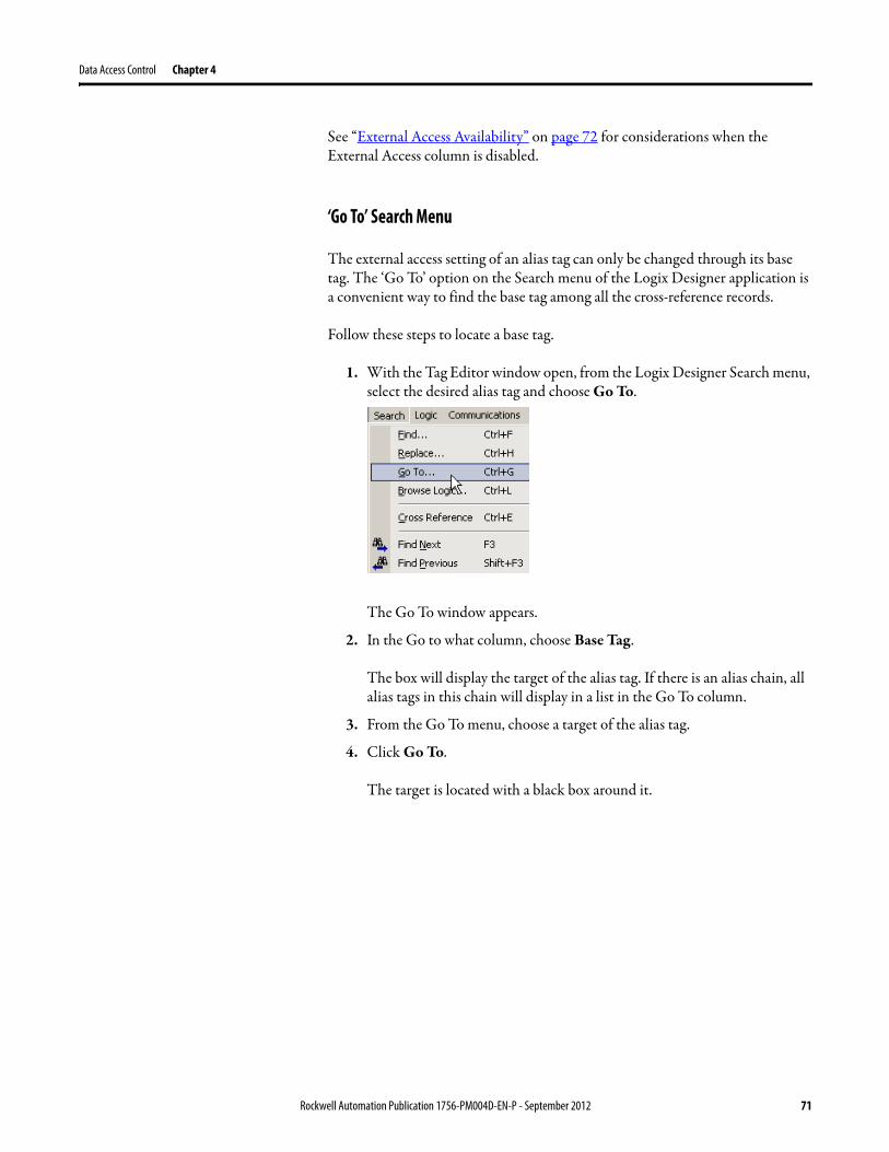
Data Access Control Chapter 4
See “External Access Availability” on page 72 for considerations when the External Access column is disabled.
‘Go To’ Search Menu
The external access setting of an alias tag can only be changed through its base tag. The ‘Go To’ option on the Search menu of the Logix Designer application is a convenient way to find the base tag among all the cross-reference records.
Follow these steps to locate a base tag.
1. With the Tag Editor window open, from the Logix Designer Search menu, select the desired alias tag and choose Go To.
The Go To window appears.
2. In the Go to what column, choose Base Tag.
The box will display the target of the alias tag. If there is an alias chain, all alias tags in this chain will display in a list in the Go To column.
3. From the Go To menu, choose a target of the alias tag.
4. Click Go To.
The target is located with a black box around it.
Rockwell Automation Publication 1756-PM004D-EN-P - September 2012 71
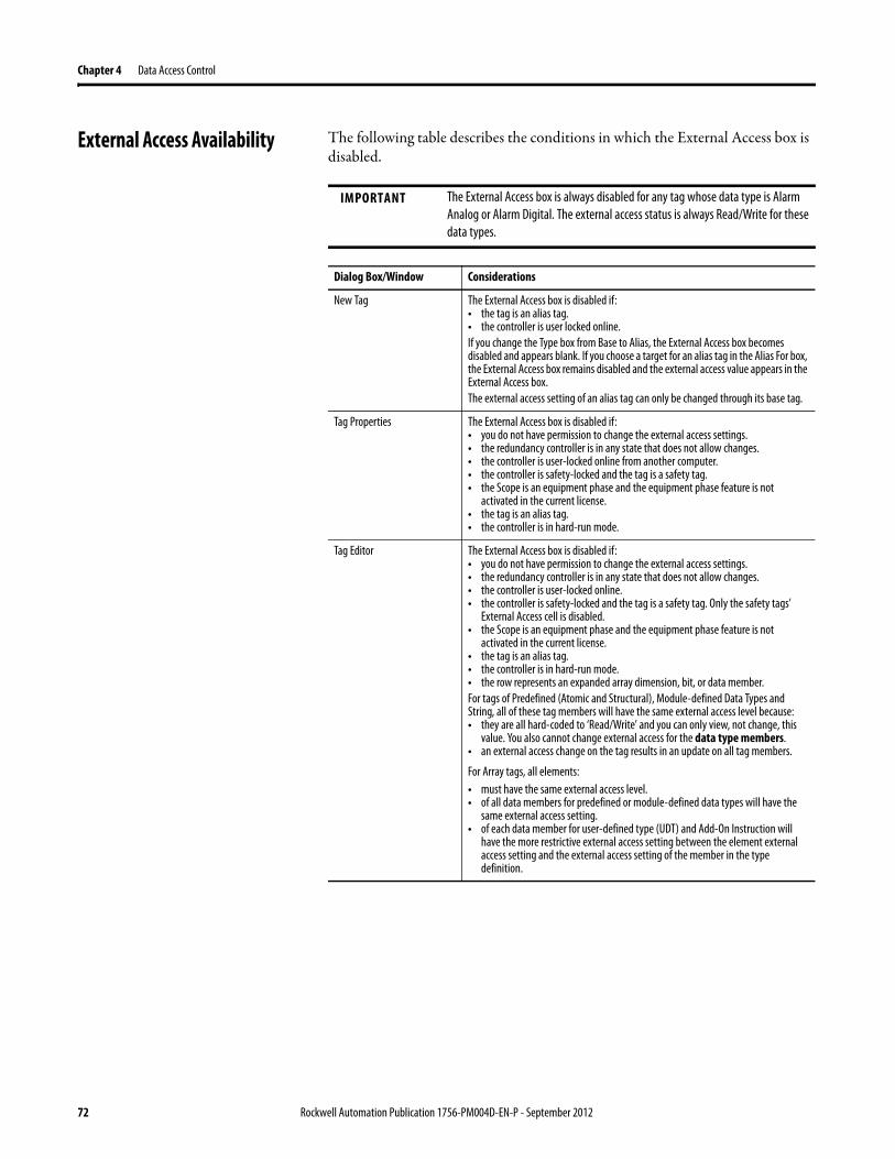
Chapter 4 Data Access Control
External Access Availability The following table describes the conditions in which the External Access box is disabled.
IMPORTANT The External Access box is always disabled for any tag whose data type is Alarm Analog or Alarm Digital. The external access status is always Read/Write for these data types.
Dialog Box/Window Considerations
New Tag The External Access box is disabled if:• the tag is an alias tag.• the controller is user locked online.If you change the Type box from Base to Alias, the External Access box becomes disabled and appears blank. If you choose a target for an alias tag in the Alias For box, the External Access box remains disabled and the external access value appears in the External Access box.The external access setting of an alias tag can only be changed through its base tag.
Tag Properties The External Access box is disabled if:• you do not have permission to change the external access settings.• the redundancy controller is in any state that does not allow changes.• the controller is user-locked online from another computer.• the controller is safety-locked and the tag is a safety tag.• the Scope is an equipment phase and the equipment phase feature is not
activated in the current license.• the tag is an alias tag.• the controller is in hard-run mode.
Tag Editor The External Access box is disabled if:• you do not have permission to change the external access settings.• the redundancy controller is in any state that does not allow changes.• the controller is user-locked online.• the controller is safety-locked and the tag is a safety tag. Only the safety tags’
External Access cell is disabled.• the Scope is an equipment phase and the equipment phase feature is not
activated in the current license.• the tag is an alias tag.• the controller is in hard-run mode.• the row represents an expanded array dimension, bit, or data member.For tags of Predefined (Atomic and Structural), Module-defined Data Types and String, all of these tag members will have the same external access level because:• they are all hard-coded to ‘Read/Write’ and you can only view, not change, this
value. You also cannot change external access for the data type members.• an external access change on the tag results in an update on all tag members.
For Array tags, all elements:• must have the same external access level.• of all data members for predefined or module-defined data types will have the
same external access setting.• of each data member for user-defined type (UDT) and Add-On Instruction will
have the more restrictive external access setting between the element external access setting and the external access setting of the member in the type definition.
72 Rockwell Automation Publication 1756-PM004D-EN-P - September 2012
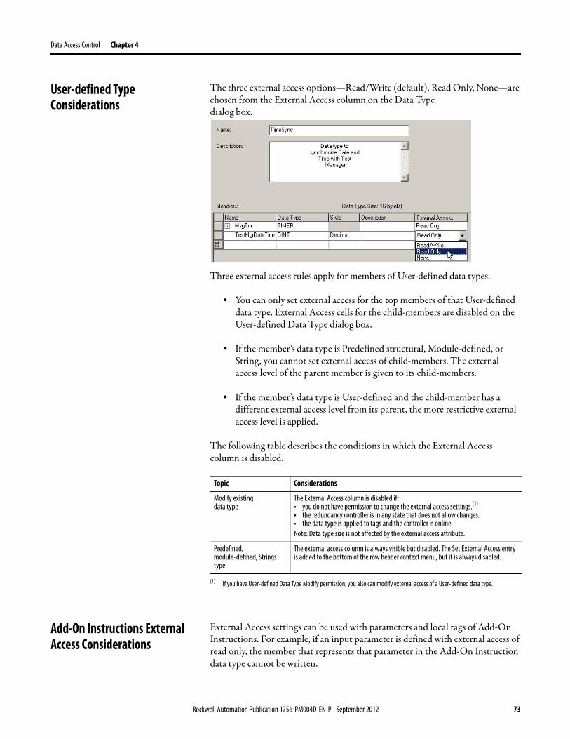
Data Access Control Chapter 4
User-defined Type Considerations
The three external access options—Read/Write (default), Read Only, None—are chosen from the External Access column on the Data Type
dialog box.
Three external access rules apply for members of User-defined data types.
• You can only set external access for the top members of that User-defined data type. External Access cells for the child-members are disabled on the User-defined Data Type dialog box.
• If the member’s data type is Predefined structural, Module-defined, or String, you cannot set external access of child-members. The external access level of the parent member is given to its child-members.
• If the member’s data type is User-defined and the child-member has a different external access level from its parent, the more restrictive external access level is applied.
The following table describes the conditions in which the External Access column is disabled.
Add-On Instructions External Access Considerations
External Access settings can be used with parameters and local tags of Add-On Instructions. For example, if an input parameter is defined with external access of read only, the member that represents that parameter in the Add-On Instruction data type cannot be written.
Topic Considerations
Modify existing
data typeThe External Access column is disabled if:• you do not have permission to change the external access settings.(1)
• the redundancy controller is in any state that does not allow changes.• the data type is applied to tags and the controller is online.Note: Data type size is not affected by the external access attribute.
(1) If you have User-defined Data Type Modify permission, you also can modify external access of a User-defined data type.
Predefined, module-defined, Strings type
The external access column is always visible but disabled. The Set External Access entry is added to the bottom of the row header context menu, but it is always disabled.
Rockwell Automation Publication 1756-PM004D-EN-P - September 2012 73
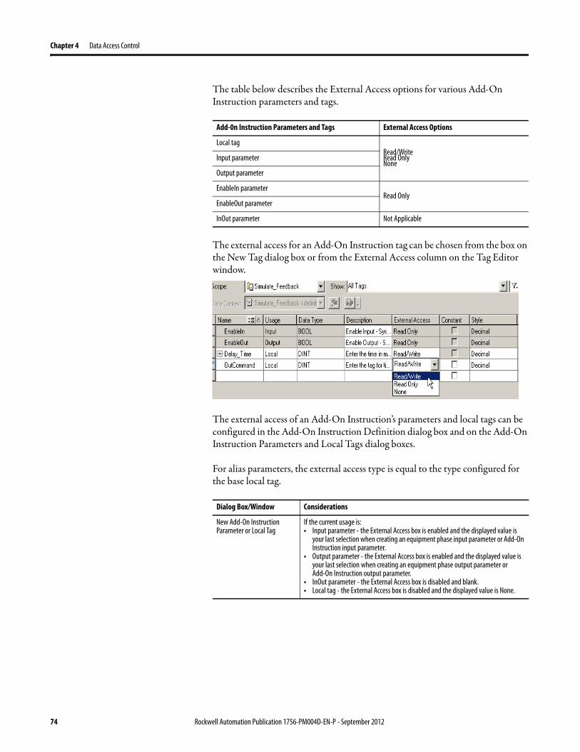
Chapter 4 Data Access Control
The table below describes the External Access options for various Add-On Instruction parameters and tags.
The external access for an Add-On Instruction tag can be chosen from the box on the New Tag dialog box or from the External Access column on the Tag Editor window.
The external access of an Add-On Instruction’s parameters and local tags can be configured in the Add-On Instruction Definition dialog box and on the Add-On Instruction Parameters and Local Tags dialog boxes.
For alias parameters, the external access type is equal to the type configured for the base local tag.
Add-0n Instruction Parameters and Tags External Access Options
Local tagRead/WriteRead OnlyNone
Input parameter
Output parameter
EnableIn parameterRead Only
EnableOut parameter
InOut parameter Not Applicable
Dialog Box/Window Considerations
New Add-On Instruction Parameter or Local Tag
If the current usage is:• Input parameter - the External Access box is enabled and the displayed value is
your last selection when creating an equipment phase input parameter or Add-On Instruction input parameter.
• Output parameter - the External Access box is enabled and the displayed value is your last selection when creating an equipment phase output parameter or Add-On Instruction output parameter.
• InOut parameter - the External Access box is disabled and blank.• Local tag - the External Access box is disabled and the displayed value is None.
74 Rockwell Automation Publication 1756-PM004D-EN-P - September 2012
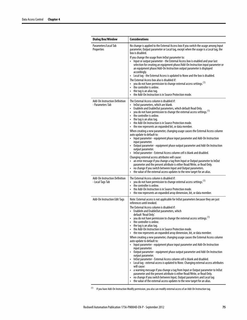
Data Access Control Chapter 4
Parameters/Local Tab Properties
No change is applied to the External Access box if you switch the usage among Input parameter, Output parameter or Local tag, except when the usage is a Local tag, the box is disabled.If you change the usage from InOut parameter to:• Input or output parameter - the External Access box is enabled and your last
selection for creating an equipment phase/Add-On Instruction input parameter or an equipment phase/Add-On Instruction output parameter is displayed accordingly.
• Local tag - the External Access is updated to None and the box is disabled.The External Access box also is disabled if:• you do not have permission to change external access settings.(1)
• the controller is online.• the tag is an alias tag.• the Add-On Instruction is in Source Protection mode.
Add-On Instruction Definition - Parameters Tab
The External Access column is disabled if:• InOut parameters, which are blank.• EnableIn and EnableOut parameters, which default Read Only.• you do not have permission to change the external access settings.(1)
• the controller is online.• the tag is an alias tag.• the Add-On Instruction is in Source Protection mode.• the row represents an expanded bit, or data member.When creating a new parameter, changing usage causes the External Access column auto update to default to:• Input parameter - equipment phase input parameter and Add-On Instruction
input parameter.• Output parameter - equipment phase output parameter and Add-On Instruction
output parameter.• InOut parameter - External Access column cell is blank and disabled.Changing external access attributes will cause:• an error message if you change a tag from Input or Output parameter to InOut
parameter and the present attribute is either Read/Write, or Read Only.• no change if you switch between Input and Output parameters.• the value of the external access updates to the new target for an alias.
Add-On Instruction Definition - Local Tags Tab
The External Access column is disabled if:• you do not have permission to change external access settings.(1)
• the controller is online.• the Add-On Instruction is in Source Protection mode.• the row represents an expanded array dimension, bit, or data member.
Add-On Instruction Edit Tags Note: External access is not applicable for InOut parameters because they are just references until invoked.The External Access column is disabled if:• EnableIn and EnableOut parameters, which
default ‘Read Only’.• you do not have permission to change the external access settings.(1)
• the controller is online.• the tag is an alias tag.• the Add-On Instruction is in Source Protection mode.• the row represents an expanded array dimension, bit, or data member.When creating a new parameter, changing usage causes the External Access column auto update to default to:• Input parameter - equipment phase input parameter and Add-On Instruction
input parameter.• Output parameter - equipment phase output parameter and Add-On Instruction
output parameter.• InOut parameter - External Access column cell is blank and disabled.• Local tag - external access is updated to None. Changing external access attributes
will cause:• a warning message if you change a tag from Input or Output parameter to InOut
parameter and the present attribute is either Read/Write, or Read Only.• no change if you switch between Input, Output parameters and Local tag• the value of the external access updates to the new target for an alias.
(1) If you have Add-On Instruction Modify permission, you also can modify external access of an Add-On Instruction tag.
Dialog Box/Window Considerations
Rockwell Automation Publication 1756-PM004D-EN-P - September 2012 75
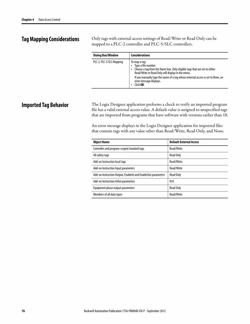
Chapter 4 Data Access Control
Tag Mapping Considerations Only tags with external access settings of Read/Write or Read Only can be mapped to a PLC-2 controller and PLC-5/SLC controllers.
Imported Tag Behavior The Logix Designer application preforms a check to verify an imported program file has a valid external access value. A default value is assigned to unspecified tags that are imported from programs that have software with versions earlier than 18.
An error message displays in the Logix Designer application for imported files that contain tags with any value other than Read/Write, Read Only, and None.
Dialog Box/Window Considerations
PLC-2, PLC-5/SLC Mapping To map a tag:• Type a file number.• Choose a tag from the Name box. Only eligible tags that are set to either
Read/Write or Read Only will display in the menu.If you manually type the name of a tag whose external access is set to None, an error message displays.
• Click OK.
Object Name Default External Access
Controller and program-scoped standard tags Read/Write
All safety tags Read Only
Add-on Instruction local tags Read/Write
Add-on Instruction Input parameters Read/Write
Add-on Instruction Output, EnableIn and EnableOut parameters Read Only
Add-on Instruction InOut parameters N/A
Equipment phase output parameters Read Only
Members of all data types Read/Write
76 Rockwell Automation Publication 1756-PM004D-EN-P - September 2012
Data Access Control Chapter 4
Constant Value Tags Version 18 and later of the application, you can designate tags as constants to protect them from being changed programatically via:
• the controller programming application.• logic in the controller.
Tags that cannot be designated as constants are User-defined type members, Add-On Instruction input and output parameters, and local tags. A check mark in the Constant box on tag creation dialog boxes and tag editor/monitor windows indicates a ‘constant’ designation.
FactoryTalk security is used to control who is permitted to modify values of constants and who can modify the constant attribute of a tag. To change the value of a constant, you must have the Tag: Modify Constant Tag Values permission. To modify the constant attribute of a tag, you must have the Tag: Modify Constant Property permission.
For details on setting permissions, see the FactoryTalk Security System Configuration Guide, publication FTSEC-QS001.
For an alias tag, the default constant setting of this tag is the same as its target tag. For all other conditions, the default value is unchecked, indicating the tag is not a constant value tag.
When you designate an InOut parameter as a constant, it cannot be written to within the Add-On Instruction.
TIP You cannot pass a constant value tag as an argument to an Output parameter of an Add-On Instruction. You cannot pass a constant tag to an InOut parameter that is not also designated as a constant value.
Rockwell Automation Publication 1756-PM004D-EN-P - September 2012 77
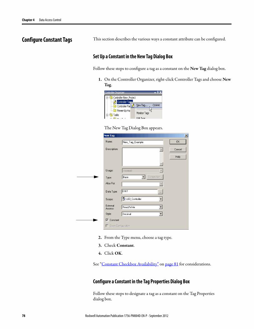
Chapter 4 Data Access Control
Configure Constant Tags This section describes the various ways a constant attribute can be configured.
Set Up a Constant in the New Tag Dialog Box
Follow these steps to configure a tag as a constant on the New Tag dialog box.
1. On the Controller Organizer, right-click Controller Tags and choose New Tag.
The New Tag Dialog Box appears.
2. From the Type menu, choose a tag type.
3. Check Constant.
4. Click OK.
See “Constant Checkbox Availability” on page 81 for considerations.
Configure a Constant in the Tag Properties Dialog Box
Follow these steps to designate a tag as a constant on the Tag Properties dialog box.
78 Rockwell Automation Publication 1756-PM004D-EN-P - September 2012
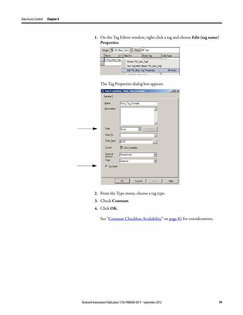
Data Access Control Chapter 4
1. On the Tag Editor window, right-click a tag and choose Edit (tag name) Properties.
The Tag Properties dialog box appears.
2. From the Type menu, choose a tag type.
3. Check Constant.
4. Click OK.
See “Constant Checkbox Availability” on page 81 for considerations.
Rockwell Automation Publication 1756-PM004D-EN-P - September 2012 79
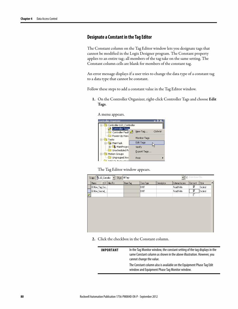
Chapter 4 Data Access Control
Designate a Constant in the Tag Editor
The Constant column on the Tag Editor window lets you designate tags that cannot be modified in the Logix Designer program. The Constant property applies to an entire tag; all members of the tag take on the same setting. The Constant column cells are blank for members of the constant tag.
An error message displays if a user tries to change the data type of a constant tag to a data type that cannot be constant.
Follow these steps to add a constant value in the Tag Editor window.
1. On the Controller Organizer, right-click Controller Tags and choose Edit Tags.
A menu appears.
The Tag Editor window appears.
2. Click the checkbox in the Constant column.
IMPORTANT In the Tag Monitor window, the constant setting of the tag displays in the same Constant column as shown in the above illustration. However, you cannot change the value.
The Constant column also is available on the Equipment Phase Tag Edit window and Equipment Phase Tag Monitor window.
80 Rockwell Automation Publication 1756-PM004D-EN-P - September 2012
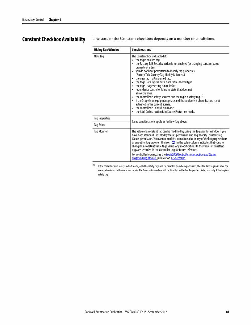
Data Access Control Chapter 4
Constant Checkbox Availability The state of the Constant checkbox depends on a number of conditions.
Dialog Box/Window Considerations
New Tag The Constant box is disabled if:• the tag is an alias tag.• the Factory Talk Security action is not enabled for changing constant value
property of a tag.• you do not have permission to modify tag properties
(Factory Talk Security Tag Modify is denied.)• the new tag is a Consumed tag.• the tag’s Data Type is not a data table-backed type.• the tag’s Usage setting is not ‘InOut’.• redundancy controller is in any state that does not
allow changes.• the controller is safety-secured and the tag is a safety tag.(1)
• if the Scope is an equipment phase and the equipment phase feature is not activated in the current license.
• the controller is in hard-run mode.• the Add-On Instruction is in Source Protection mode.
(1) If the controller is in safety-locked mode, only the safety tags will be disabled from being accessed, the standard tags will have the same behavior as in the unlocked mode. The Constant value box will be disabled in the Tag Properties dialog box only if the tag is a safety tag.
Tag PropertiesSame considerations apply as for New Tag above.
Tag Editor
Tag Monitor The value of a constant tag can be modified by using the Tag Monitor window if you have both standard Tag: Modify Values permission and Tag: Modify Constant Tag Values permission. You cannot modify a constant value in any of the language editors or any other tag browser. The icon in the Value column indicates that you are changing a constant value tag’s value. Any modifications to the values of constant tags are recorded in the Controller Log for future reference.For controller logging, see the Logix5000 Controllers Information and Status Programming Manual, publication 1756-PM015.
Rockwell Automation Publication 1756-PM004D-EN-P - September 2012 81
Chapter 4 Data Access Control
Add-On Instructions Constant Value Considerations
The Constant attribute applies only to InOut parameters. The default setting of the property will be not a Constant Value.
The Constant attribute will not apply to Input, Output, EnableIn and EnableOut Add-On Instruction parameters. It will not apply to Add-On Instruction Local tags.
By denoting an InOut parameter of an Add-On Instruction as a constant, it means that within the Add-On Instruction, that parameter cannot be written to. The project will fail verification if this type of write is attempted.
Appropriate usage of Constant tags is monitored by logic verification.
82 Rockwell Automation Publication 1756-PM004D-EN-P - September 2012
Index
Aaccess
external 65add extended properties to a tag 33add extended properties to user-defined data type 43Add-On Instruction
constant value considerations 82external access variables 74
addressassign indirect 51tag 47tag I/O module 19
aliascreate 50show/hide 49use of 48
arraycalculate subscript 52create 38index through 51organize 29overview 35
availabilityconstant value 81external access 72, 73
Bbuffer
I/O data 20
Ccommunication
format 8ownership 9
I/O module 8module I/O configuration 7
compatiblekeying 12
configureexternal access 66I/O module 7
connectiondirect 8listen-only 9overview 8rack-optimized 8reduce the number of 8
considerationsAdd-On Instructions
constant value 82external access 73
external access 72, 73user-defined data type external access 73
constantvalue
availability 81dialog box 78tag editor 80
tag properties 78value configuration 78value tags 77
controllertags 27
use of 27create
alias 50tag 33user-defined data type 41
Ddata
blockSee array (create)
force 60, 61I/O 19table
?See tag (organize)type
choose 25overview 25structure 25
descriptiontag 44user-defined data type 44
direct connection 8disable
electronic keying 17force 58, 62
documenttag
description 44user-defined data type 44
Eelectronic keying
I/O 12enable
force 57exact match
electronic keying 13keying 12
expressioncalculate array subscript 52
extended properties 25adding extended properties to a
tag 33user-defined data type 43
externalaccess 65
Add-On Instruction 73availability 72, 73configure 66configure tag dialog 67configure tag properties 69options 66user-defined data type considerations 73view tag editor 70
Rockwell Automation Publication 1756-PM004D-EN-P - September 2012 83
Index
Ffile
?See arrayforce
disable 58, 62enable 57options 60remove 58, 62safety precautions 57tag 60, 61
function block diagramforce a value 57
Gglobal data
?See scope
II/O module
buffer data 20communication format 8configuration 7configure 7document
?See aliaselectronic keying 12ownership 9synchronize with logic 20tag address 19update period 8
index See indirect address
indirect address 51format 47use of expression 52
Kkeying
?See electronic keying
Lladder logic
force a value 57override a value 57
local dataSee scope
Logix Designer application 5
Mmemory
allocation for tags 25Min and Max for DINT, INT, LINT, SINT, and REAL data types 34, 43module
I/O configuration 7
Nname
guidelines for tag 29reuse of tag name 27
Oownership
I/O module 9
Ppass-through description 44program
tags 27project documentation 55
Rrack-optimized connection 8remove
force 58, 62requested packet interval (RPI) 8
Sscope
guidelines 29tag 27
sequential function chartforce element 57
structurecreate 41organize 29overview 25user-defined 39
structured textforce a value 57
Studio 5000 Engineering and Design Environment 5symbol
See alias.
Ttag
address 47alias 48array 35assign dimensions 38constant value 77
configuration 78create 33create alias 50data
type 25dialog
external access 67editor
view external access 70
84 Rockwell Automation Publication 1756-PM004D-EN-P - September 2012
Index
force 60, 61guidelines 29I/O 19mapping
considerations 76memory allocation 25name 27organize 29overview 23properties
external access 69reuse of name 27scope 27type 24
Uuser-defined data type
create 41external access variables 73guidelines 40overview 39
Vvariables
constant value 81external access 72, 73user-defined data type
external access 73
Rockwell Automation Publication 1756-PM004D-EN-P - September 2012 85

Index
86 Rockwell Automation Publication 1756-PM004D-EN-P - September 2012

Rockwell Otomasyon Ticaret A.Ş., Kar Plaza İş Merkezi E Blok Kat:6 34752 İçerenköy, İstanbul, Tel: +90 (216) 5698400
Publication 1756-PM004D-EN-P - September 2012 88Supersedes Publication 1756-PM004C-EN-P - October 2009 Copyright © 2012 Rockwell Automation, Inc. All rights reserved. Printed in the U.S.A.
Rockwell Automation Support
Rockwell Automation provides technical information on the Web to assist you in using its products. At http://www.rockwellautomation.com/support/, you can find technical manuals, a knowledge base of FAQs, technical and application notes, sample code and links to software service packs, and a MySupport feature that you can customize to make the
best use of these tools.
For an additional level of technical phone support for installation, configuration, and troubleshooting, we offer TechConnect support programs. For more information, contact your local distributor or Rockwell Automation representative, or visit http://www.rockwellautomation.com/support/.
Installation Assistance
If you experience a problem within the first 24 hours of installation, review the information that is contained in this manual. You can contact Customer Support for initial help in getting your product up and running.
New Product Satisfaction Return
Rockwell Automation tests all of its products to ensure that they are fully operational when shipped from the manufacturing facility. However, if your product is not functioning and needs to be returned, follow these procedures.
Documentation Feedback
Your comments will help us serve your documentation needs better. If you have any suggestions on how to improve this document, complete this form, publication RA-DU002, available at http://www.rockwellautomation.com/literature/.
United States or Canada 1.440.646.3434
Outside United States or Canada Use the Worldwide Locator at http://www.rockwellautomation.com/support/americas/phone_en.html, or contact your local Rockwell Automation representative.
United States Contact your distributor. You must provide a Customer Support case number (call the phone number above to obtain one) to your distributor to complete the return process.
Outside United States Please contact your local Rockwell Automation representative for the return procedure.